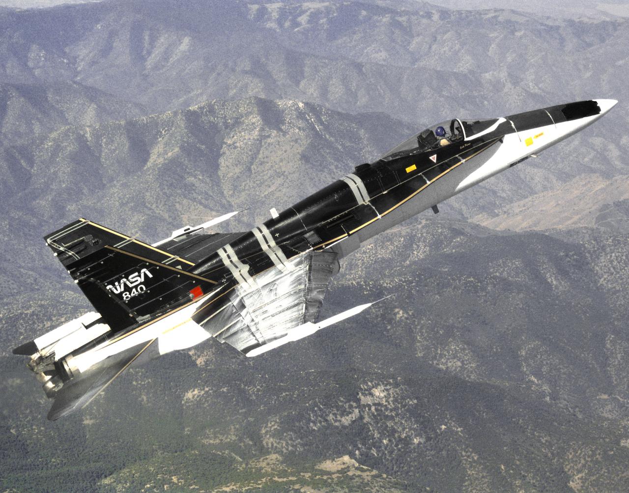
The modified F-18 High Alpha Research Vehicle (HARV) carries out air flow studies on a flight from the Dryden Flight Research Center, Edwards, California. Using oil, researchers were able to track the air flow across the wing at different speeds and angles of attack. A thrust vectoring system had been installed on the engines' exhaust nozzles for the high angle of attack research program. The thrust vectoring system, linked to the aircraft's flight control system, moves a set of three paddles on each engine to redirect thrust for directional control and increased maneuverability at angles of attack at up to 70 degrees.
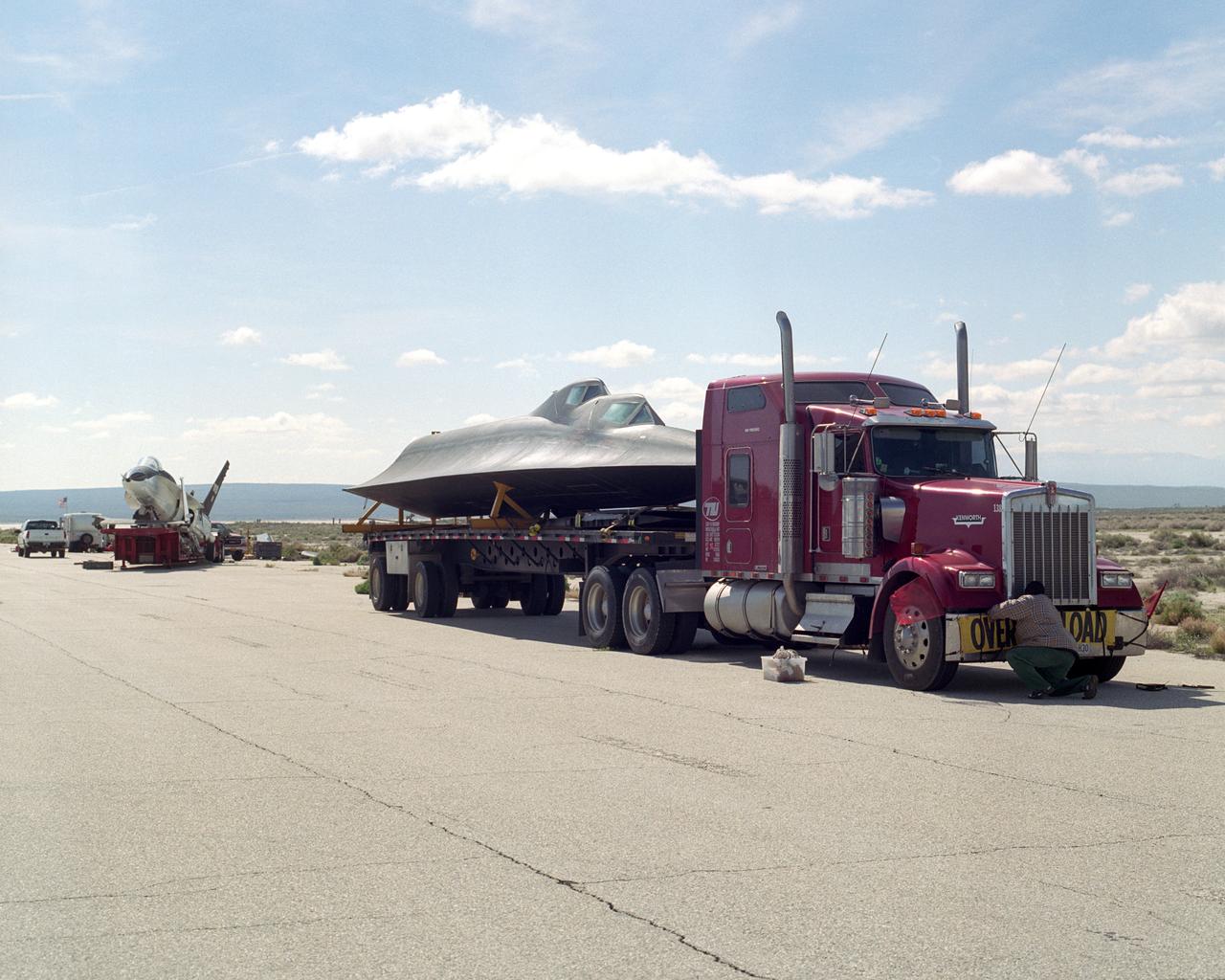
Dryden Flight Research Center's SR-71B Blackbird aircraft, NASA tail number 831, is destined for the Kalamazoo Air Zoo museum in Kalamazoo, Mich., and the F-18 High Angle-of-Attack Research Vehicle (HARV) aircraft, NASA tail number 840, is going to the Virginia Air and Space Center in Hampton, Va. NASA's SR-71B was one of only two SR-71 trainer aircraft built, and served NASA in that role, as well as for some high-speed research, from 1991 to 1999. The F-18 HARV provided some of the most comprehensive data on the high-angle-of-attack flight regime, flying at angles of up to 70 degrees from the horizontal. The HARV flew 385 research flights at Dryden from 1987 through 1996.
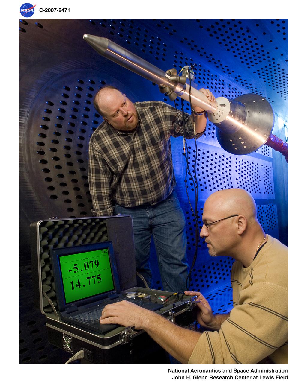
Orion Capsule and Launch Abort System (LAS) installed in the NASA Glenn 8x6 Supersonic Wind Tunnel for testing. This test is an Aero Acoustic test of the LAS. Pictured is the calibration of the model's angle of attack
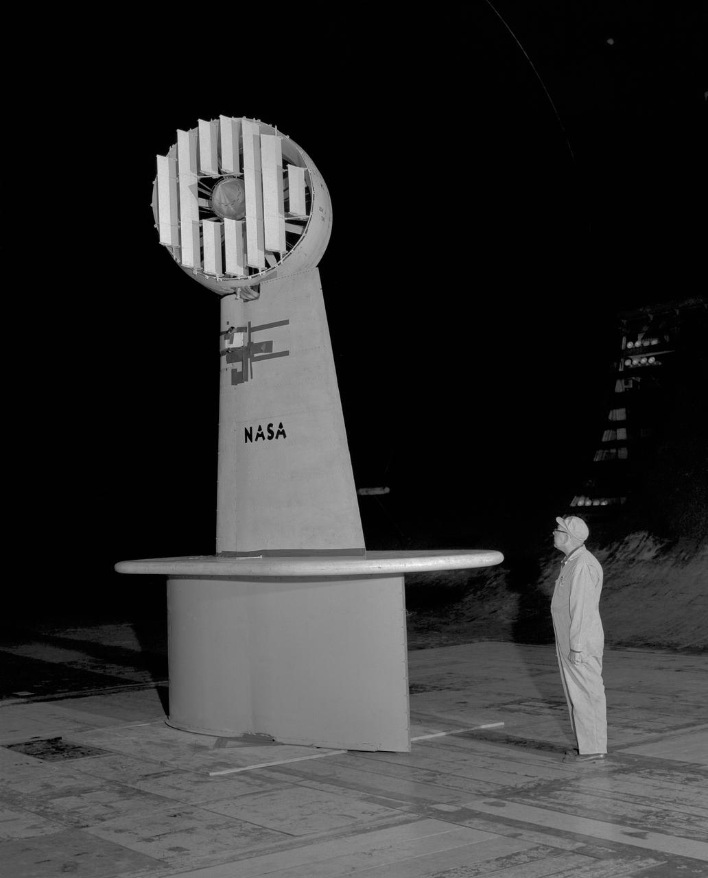
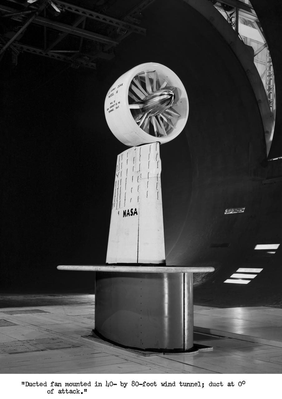
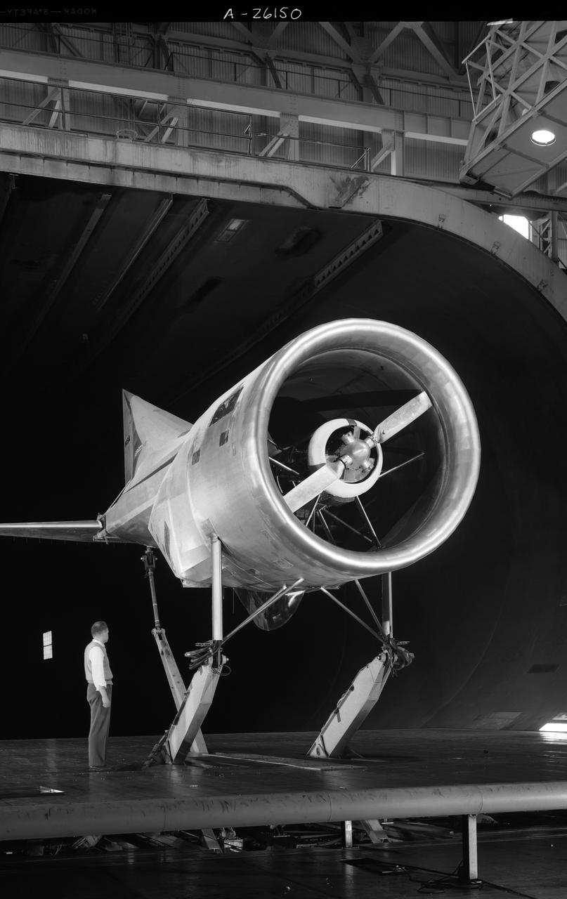
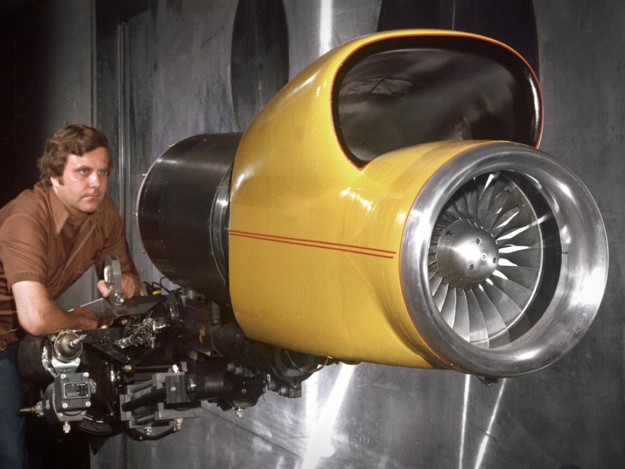
3/4 rear view of ducted fan model with cascade exit vane in Ames 40x80 foot wind tunnel, with Tom Seymore, mechanic for Ames.
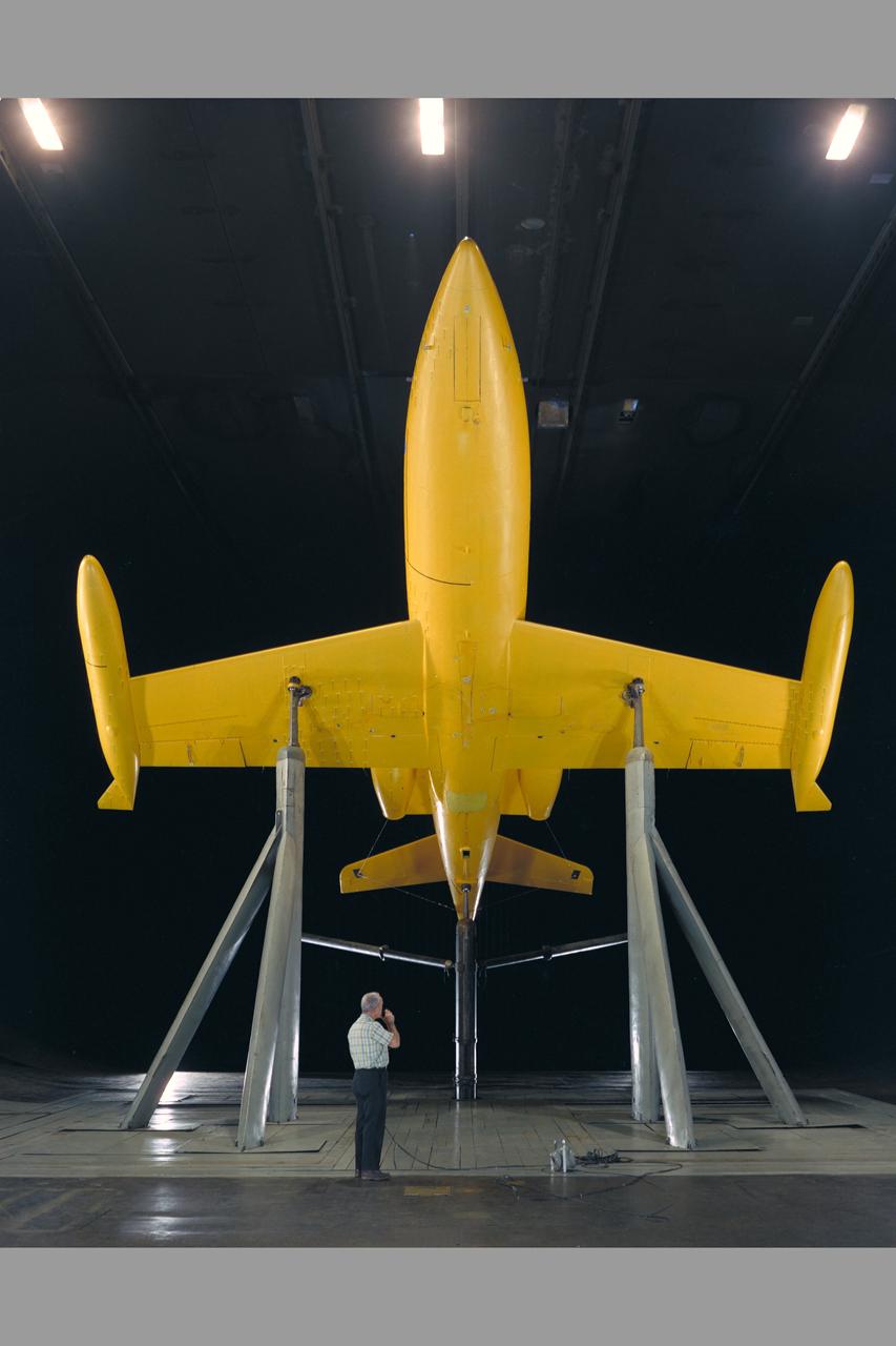
Lear Jet in 40 x 80 ft. Wind Tunnel with Ed Varrette. Angle of Attack=40 degrees.

Lear Jet in 40 x 80 ft. Wind Tunnel with Ed Varrette. Angle of Attack=0 degrees.
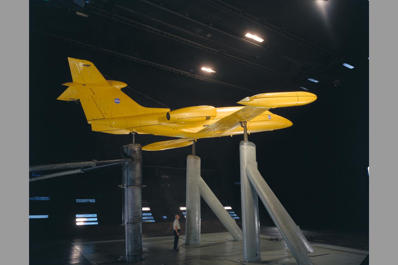
Lear Jet in 40 x 80 ft. Wind Tunnel with Ed Varrette. Angle of Attack=0 degrees.
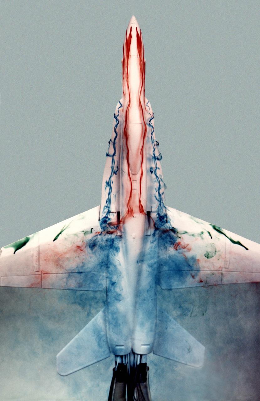
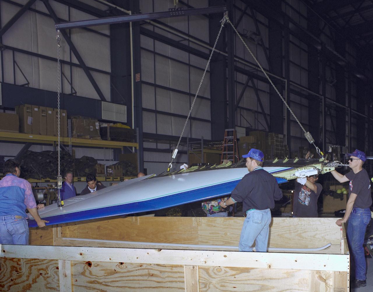
This image shows a plastic 1/48-scale model of an F-18 aircraft inside the "Water Tunnel" more formally known as the NASA Dryden Flow Visualization Facility. Water is pumped through the tunnel in the direction of normal airflow over the aircraft; then, colored dyes are pumped through tubes with needle valves. The dyes flow back along the airframe and over the airfoils highlighting their aerodynamic characteristics. The aircraft can also be moved through its pitch axis to observe airflow disruptions while simulating actual flight at high angles of attack. The Water Tunnel at NASA's Dryden Flight Research Center, Edwards, CA, became operational in 1983 when Dryden was a Flight Research Facility under the management of the Ames Research Center in Mountain View, CA. As a medium for visualizing fluid flow, water has played a significant role. Its use dates back to Leonardo da Vinci (1452-1519), the Renaissance Italian engineer, architect, painter, and sculptor. In more recent times, water tunnels have assisted the study of complex flows and flow-field interactions on aircraft shapes that generate strong vortex flows. Flow visualization in water tunnels assists in determining the strength of vortices, their location, and possible methods of controlling them. The design of the Dryden Water Tunnel imitated that of the Northrop Corporation's tunnel in Hawthorne, CA. Called the Flow Visualization Facility, the Dryden tunnel was built to assist researchers in understanding the aerodynamics of aircraft configured in such a way that they create strong vortex flows, particularly at high angles of attack. The tunnel provides results that compare well with data from aircraft in actual flight in another fluid-air. Other uses of the tunnel have included study of how such flight hardware as antennas, probes, pylons, parachutes, and experimental fixtures affect airflow. The facility has also been helpful in finding the best locations for emitting smoke from flight vehicles for flow vi
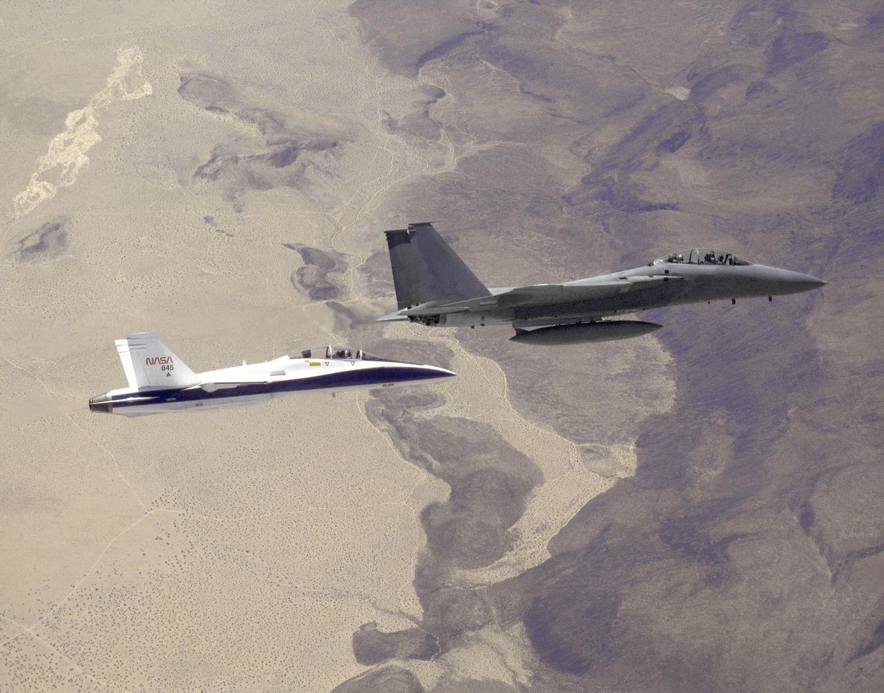
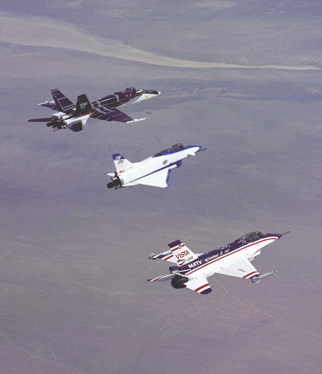
The three thrust-vectoring aircraft at Edwards, California, each capable of flying at extreme angles of attack, cruise over the California desert in formation during flight in March 1994. They are, from left, NASA's F-18 High Alpha Research Vehicle (HARV), flown by the NASA Dryden Flight Research Center; the X-31, flown by the X-31 International Test Organization (ITO) at Dryden; and the Air Force F-16 Multi-Axis Thrust Vectoring (MATV) aircraft.
The three thrust-vectoring aircraft at Edwards, California, each capable of flying at extreme angles of attack, cruise over the California desert in formation during flight in March 1994. They are, from left, NASA's F-18 High Alpha Research Vehicle (HARV), flown by the NASA Dryden Flight Research Center; the X-31, flown by the X-31 International Test Organization (ITO) at Dryden; and the Air Force F-16 Multi-Axis Thrust Vectoring (MATV) aircraft.
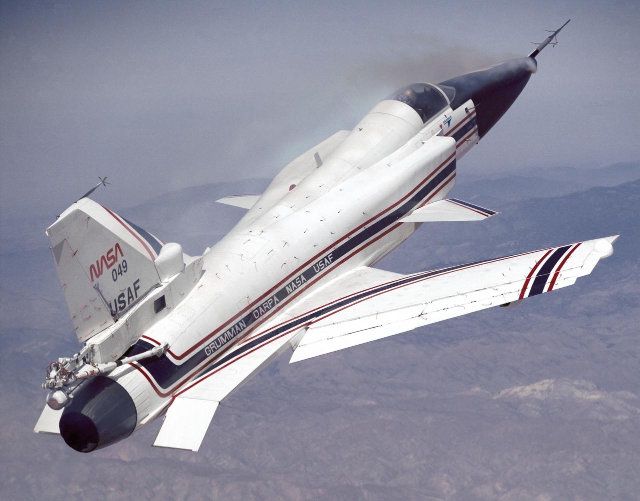
This photo shows the X-29 during a 1991 research flight. Smoke generators in the nose of the aircraft were used to help researchers see the behavior of the air flowing over the aircraft. The smoke here is demonstrating forebody vortex flow. This mission was flown September 10, 1991, by NASA research pilot Rogers Smith.
Vertol-76 Descent Test. Tilt Wing airplane prop rig at 80 deg. Angle of attack, in the 40x80 foot wind tunnel at NASA's Ames Research Center.
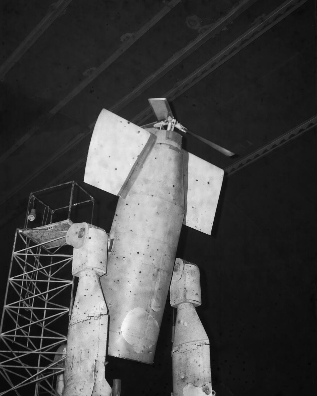
Wind Tunnel investigation of ducted fan though 180 deg angle of attack. 3/4 front view of Doak ducted fan, semi-span model with tufts.
Douglas F5D Skylancer fighter modified with ogee wing planform designed for Mach 2 flight. Shown is the effect of vortex flow on wing tuft alignment in low-speed, high angle-of-attack flight.
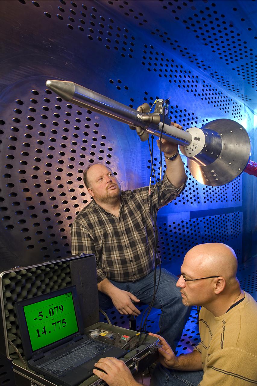
Orion Capsule and Launch Abort System (LAS) installed in the NASA Glenn 8x6 Supersonic Wind Tunnel for testing. This test is an Aero Acoustic test of the LAS. Pictured is the calibration of the model's angle of attack
Collins Aerodyne vertical take-off and landing (VTOL) aircraft investigations. Ground plane support system. 3/4 front view. Dave Koening (from Collins Aerodyne) in photo. Mounted on variable height struts, ground board system, zero degree angle of attack. 01/11/1960
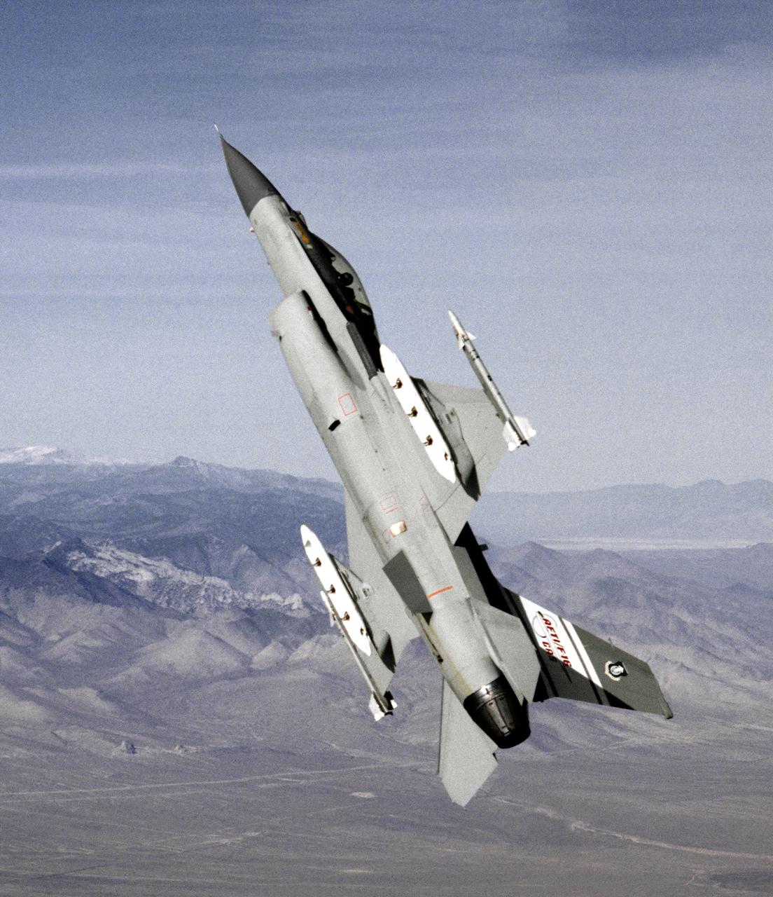
The AFTI F-16 flying at high angle of attack, shown in the final configuration and paint finish. Dummy Sidewinder air-to-air missles are attached to the wing tips. The white objects visible on the wing racks represent practice bomb dispensers, used in weapon tests.
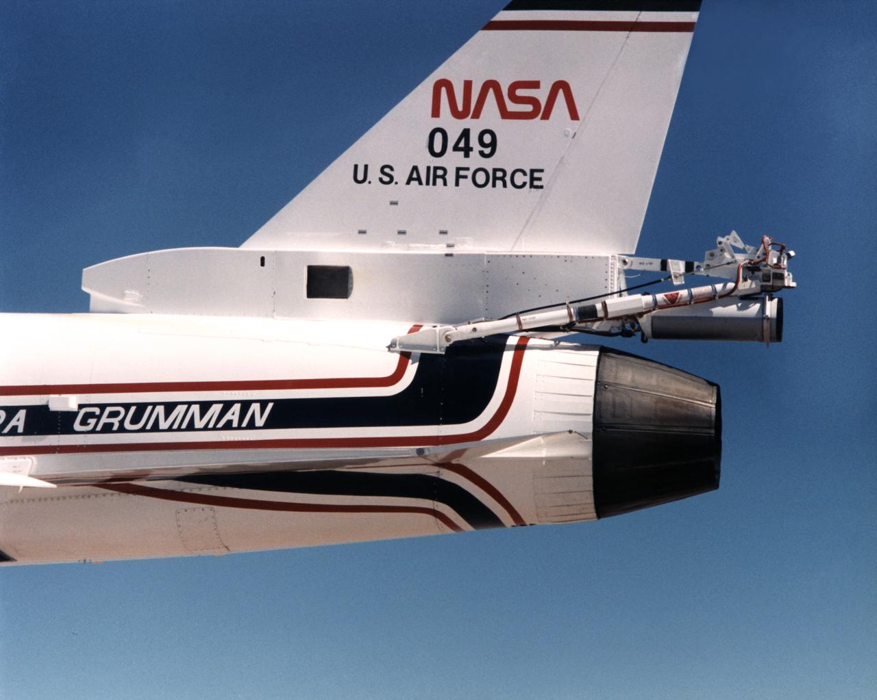
Because the number two X-29 at NASA's Ames-Dryden Flight Research Facility (later the Dryden Flight Research Center) flew at higher angles of attack than the number one aircraft, it required a spin chute system for safety. The system deployed a parachute for recovery of the aircraft if it inadvertently entered an uncontrolled spin. Most of the components of the spin chute system were located on a truss at the aft end of the aircraft. In addition, there were several cockpit modifications to facilitate use of the chute. The parachute was made of nylon and was of the conical ribbon type.
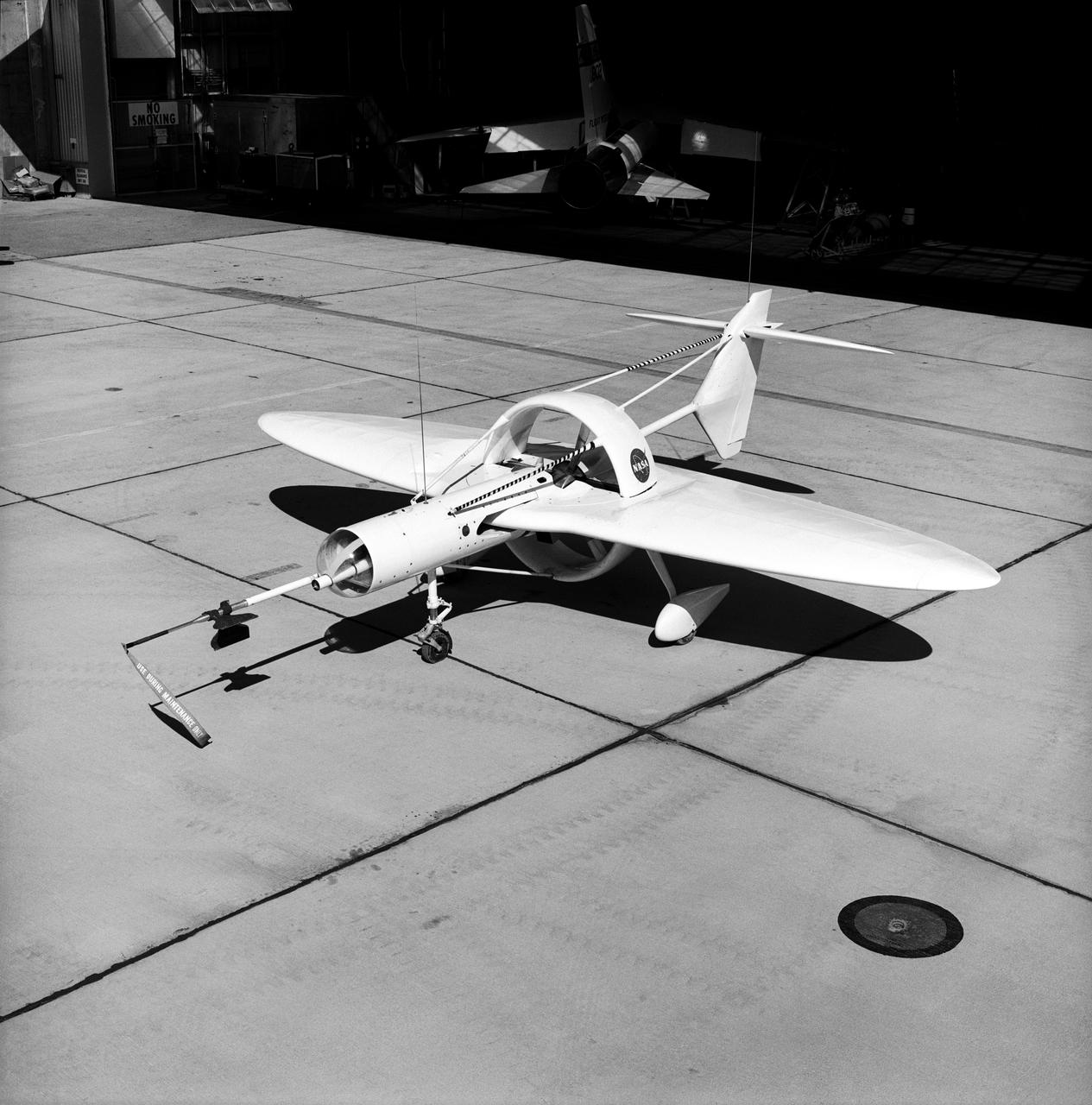
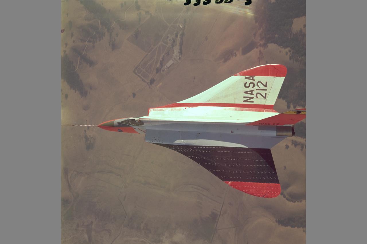
This 1976 photograph of the Oblique Wing Research Aircraft was taken in front of the NASA Flight Research Center hangar, located at Edwards Air Force Base, California. In the photograph the noseboom, pitot-static probe, and angles-of-attack and sideslip flow vanes(covered-up) are attached to the front of the vehicle. The clear nose dome for the television camera, and the shrouded propellor for the 90 horsepower engine are clearly seen.
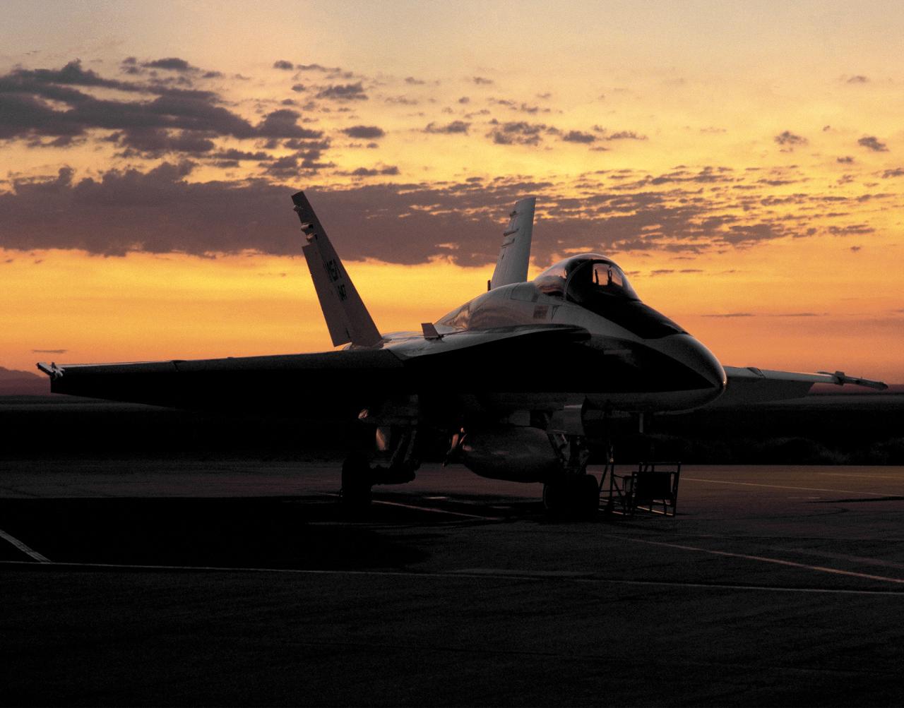
One of NASA's F/A-18 Hornets on the ramp at the Dryden Flight Research Center, Edwards, California at dawn August 6, 1993. F-18 aircraft, on loan to NASA by the U.S. Navy, were flown at Dryden as support aircraft and as research testbeds. As support aircraft, they were used primarily for safety chase, pilot proficiency and aerial photography. As research aircraft, they were involved in thrust vectoring and high angle of attack research, as well as numerous smaller scale experiments.
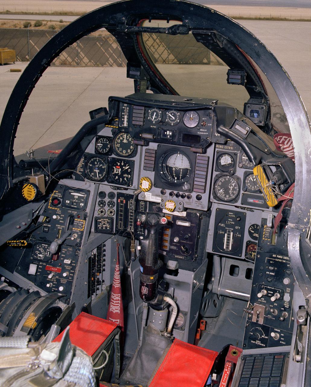
View of the cockpit of NASA's F-14, tail number 991. This aircraft was the first of a series of post-Vietnam fighters, followed by the F-15, F-16, and F-18. They were designed for maneuverability in air-to-air combat. The F-14s had a spin problem that posed problems for its ability to engage successfully in a dogfight, since it tended to depart from controlled flight at the high angles of attack that frequently occur in close-in engagements.

Outlined with gold stripes are the hinged nose strakes, modifications made to NASA's F-18 HARV (High Alpha Research Vehicle) at the Dryden Flight Research Center, Edwards, California. Actuated Nose Strakes for Enhanced Rolling (ANSER) were installed to fly the third and final phase in the HARV flight test project. Normally folded flush, the units -- four feet long and six inches wide -- can be opened independently to interact with the nose vortices to produce large side forces for control. Early wind tunnel tests indicated that the strakes would be as effective in yaw control at high angles of attack as rudders are at lower angles. Testing involved evaluation of the strakes by themselves as well as combined with the aircraft's Thrust Vectoring System. The strakes were designed by NASA's Langley Research Center, then installed and flight tested at Dryden.
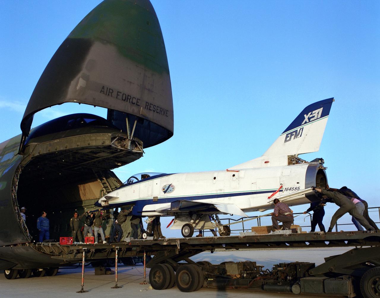
The X-31 Enhanced Fighter Maneuverability Technology Demonstrator Aircraft, based at the NASA Dryden Flight Research Center, Edwards, California, begins rolling aboard an Air Force Reserve C-5 transport which ferried it on May 22, 1995 to Europe where it was flown in the Paris Air Show in June 1995. To fit in the C-5 the right wing of the X-31 had to be removed. At the air show, the X-31 demonstrated the value of using thrust vectoring (directing engine exhaust flow) coupled with advanced flight control systems to provide controlled flight at very high angles of attack.
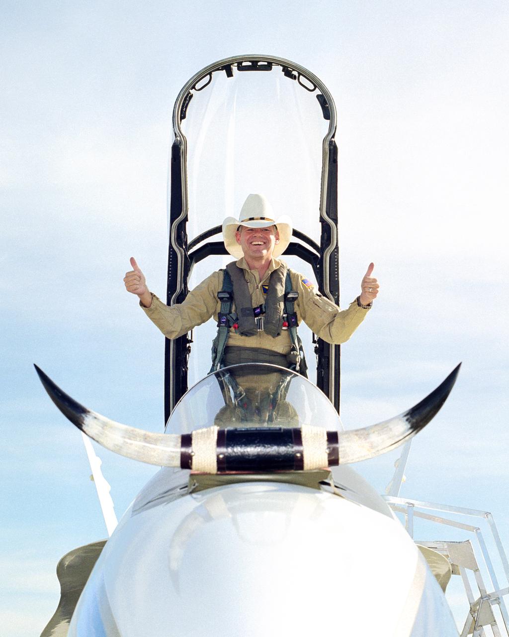
In a lighter mood, Ed Schneider gives a "thumbs-up" after his last flight at the Dryden Flight Research Center on September 19, 2000. Schneider arrived at the NASA Ames-Dryden Flight Research Facility on July 5, 1982, as a Navy Liaison Officer, becoming a NASA research pilot one year later. He has been project pilot for the F-18 High Angle-of-Attack program (HARV), the F-15 aeronautical research aircraft, the NASA B-52 launch aircraft, and the SR-71 "Blackbird" aircraft. He also participated in such programs as the F-8 Digital Fly-By-Wire, the FAA/NASA 720 Controlled Impact Demonstration, the F-14 Automatic Rudder Interconnect and Laminar Flow, and the F-104 Aeronautical Research and Microgravity projects.
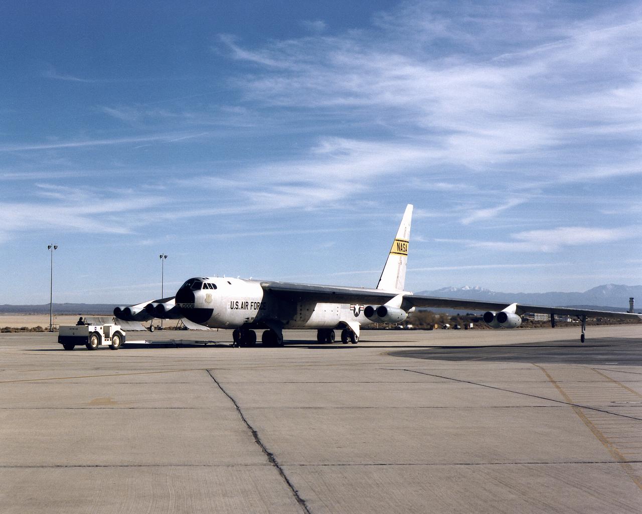
Dryden B-52 Launch Aircraft on Dryden Ramp
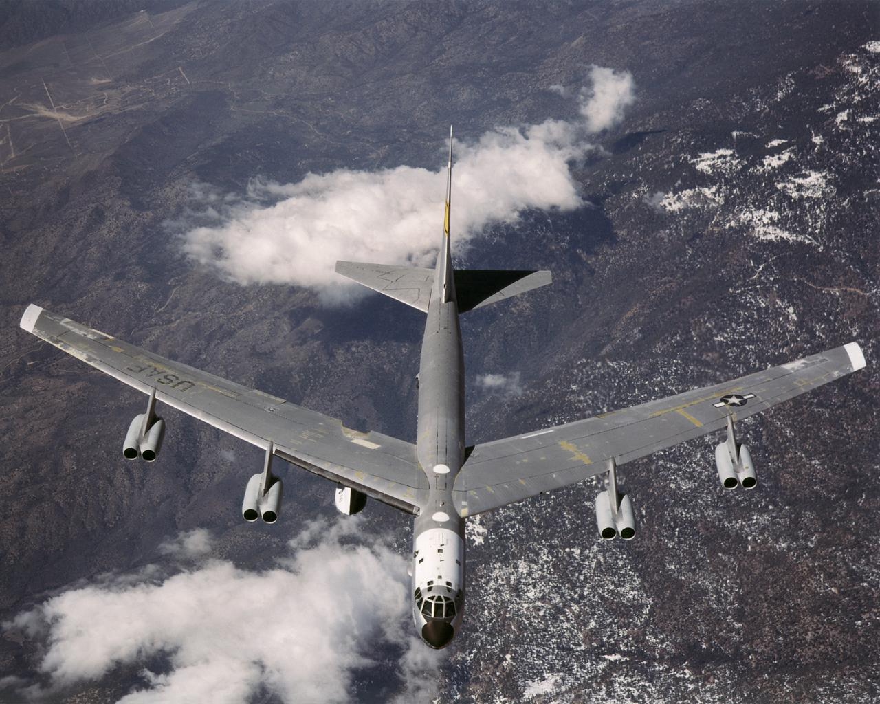
B-52 Launch Aircraft in Flight
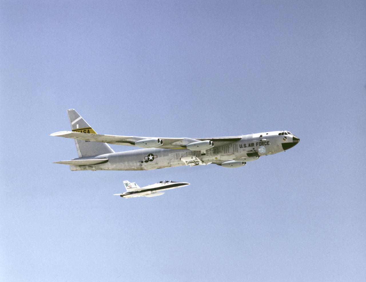
Dryden B-52 Launch Aircraft Accompanied by an F-18 Safety Chase Commemorating 40th Anniversary of Research Flights
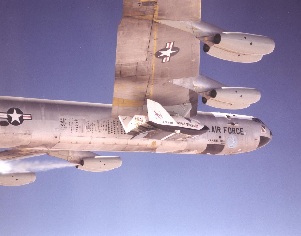
This photo shows one of the X-38 lifting-body research vehicles mated to NASA's B-52 mothership in flight prior to launch. The B-52 has been a workhorse for the Dryden Flight Research Center for more than 40 years, carrying numerous research vehicles aloft and conducting a variety of other research flight experiments.
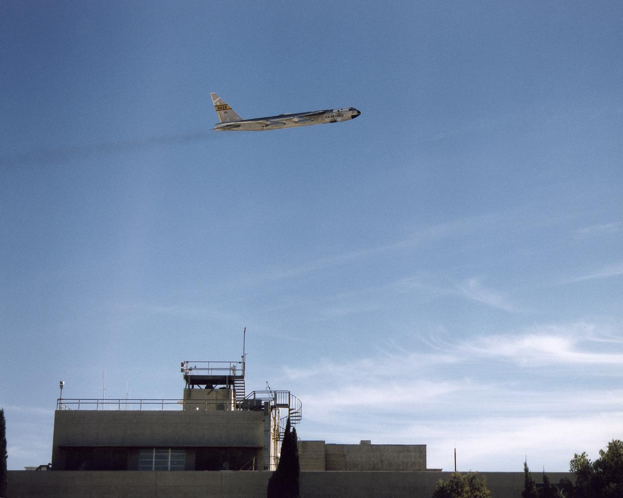
Dryden B-52 Launch Aircraft in Flight over Dryden
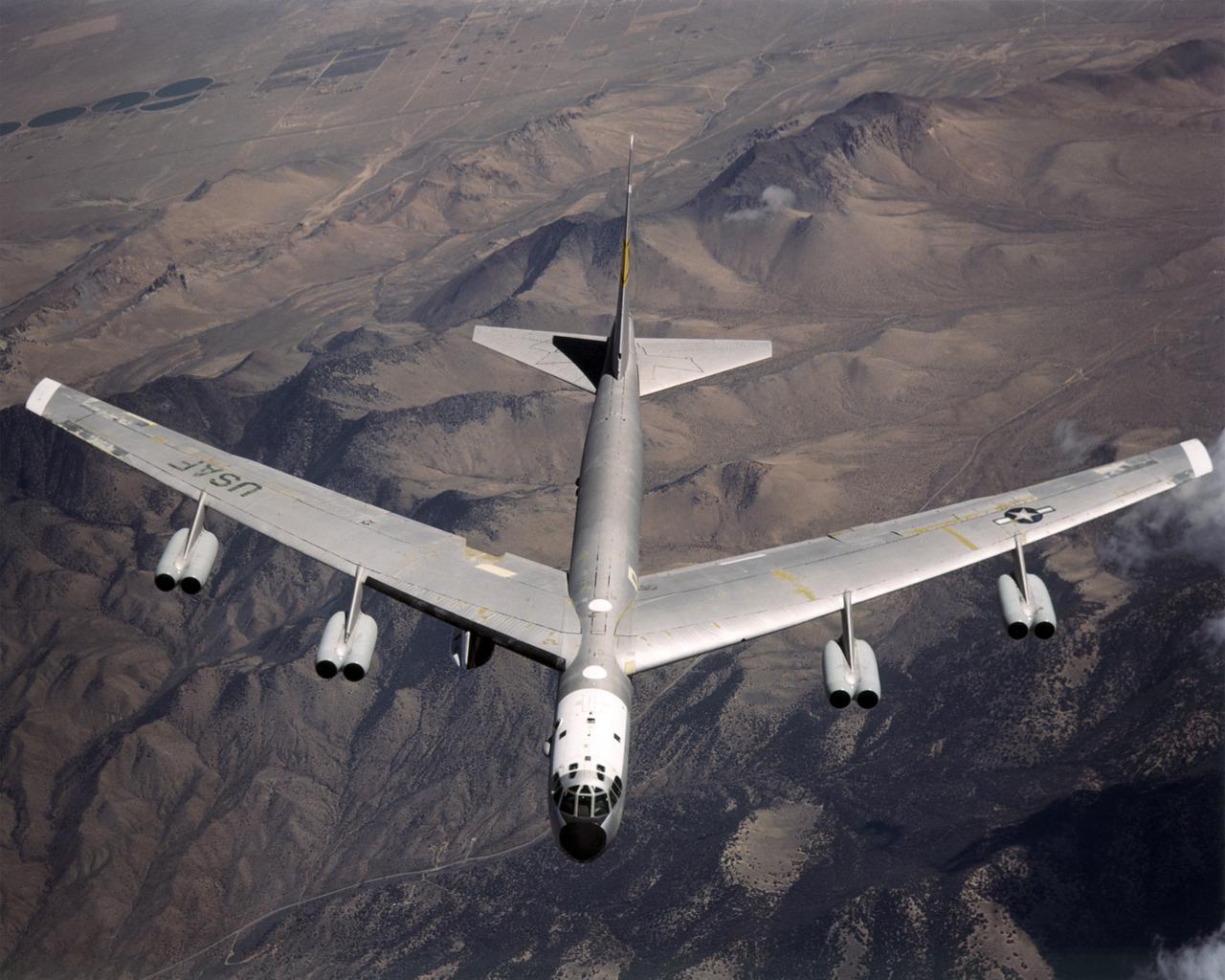
B-52 Launch Aircraft in Flight
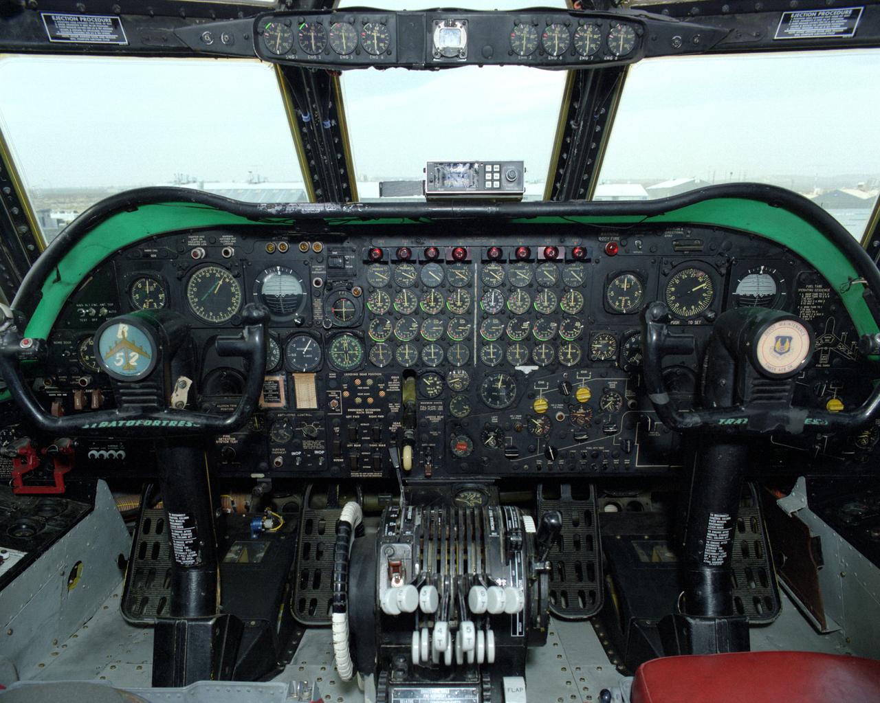
B-52B Cockpit Instrument Panel
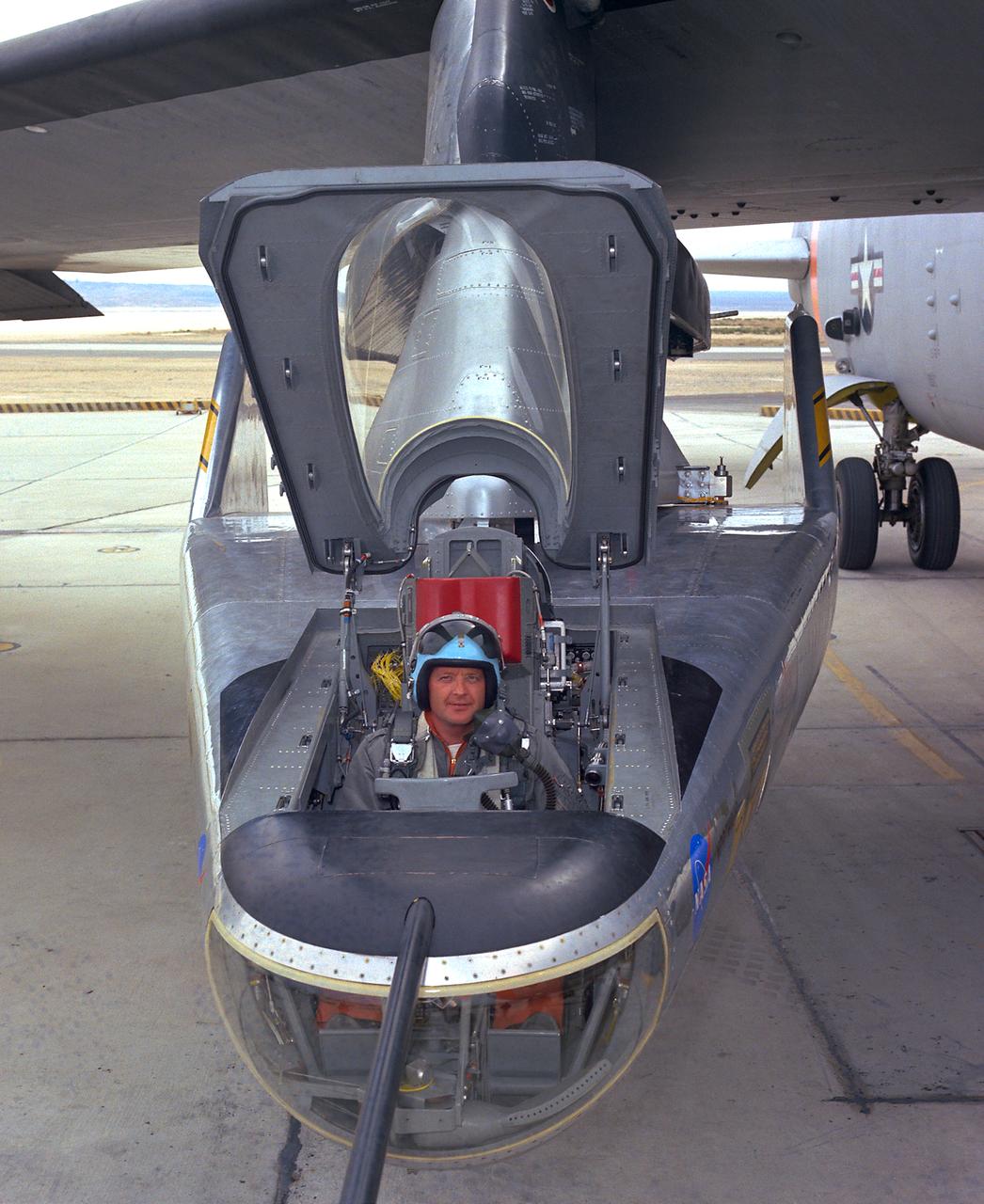
NASA research pilot Milt Thompson sits in the M2-F2 "heavyweight" lifting body research vehicle before a 1966 test flight. The M2-F2 and the other lifting-body designs were all attached to a wing pylon on NASA’s B-52 mothership and carried aloft. The vehicles were then drop-launched and, at the end of their flights, glided back to wheeled landings on the dry lake or runway at Edwards AFB. The lifting body designs influenced the design of the Space Shuttle and were also reincarnated in the design of the X-38 in the 1990s.

B-52 Launch Aircraft in Flight
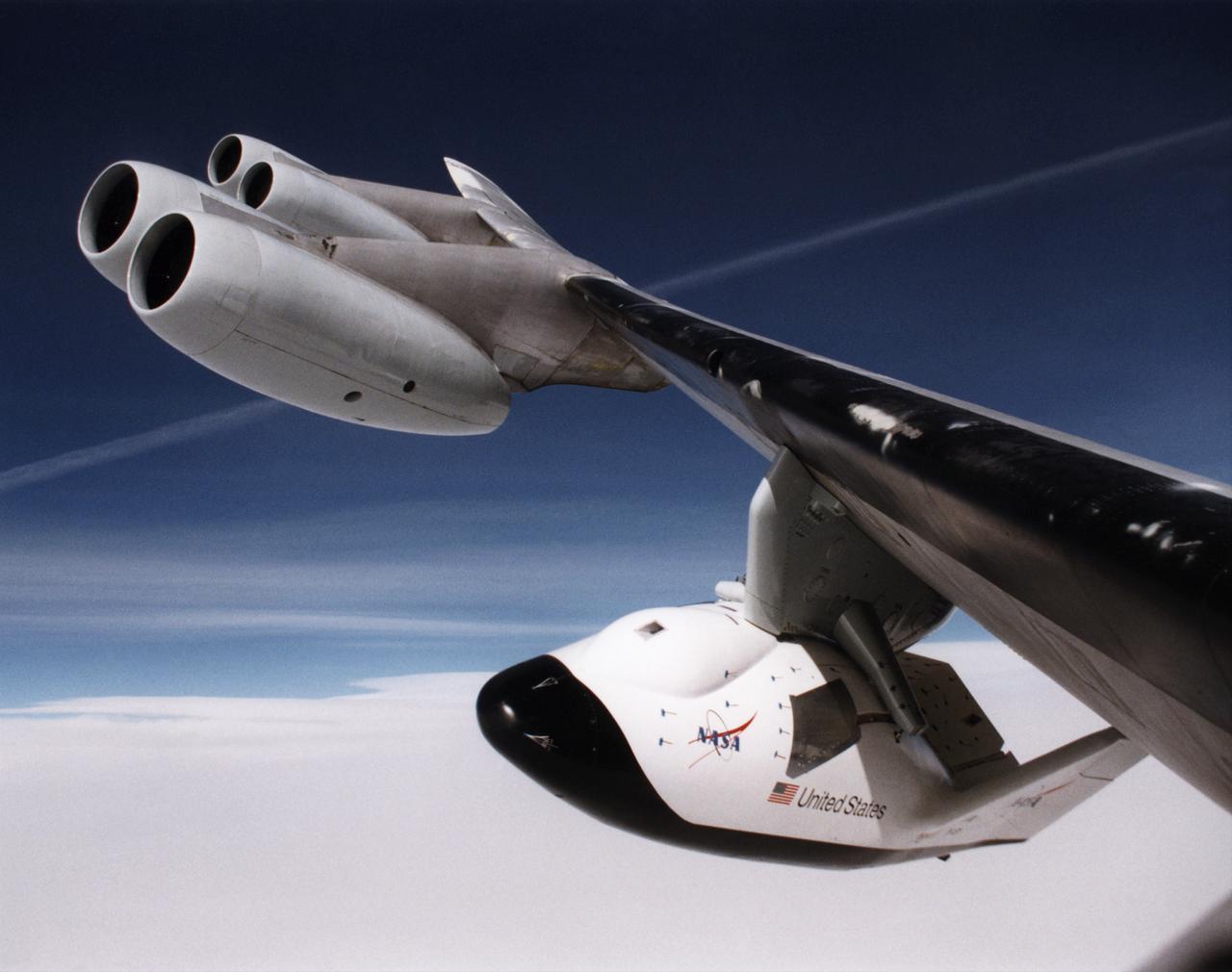
A unique, close-up view of the X-38 under the wing of NASA's B-52 mothership prior to launch of the lifting-body research vehicle. The photo was taken from the observation window of the B-52 bomber as it banked in flight.
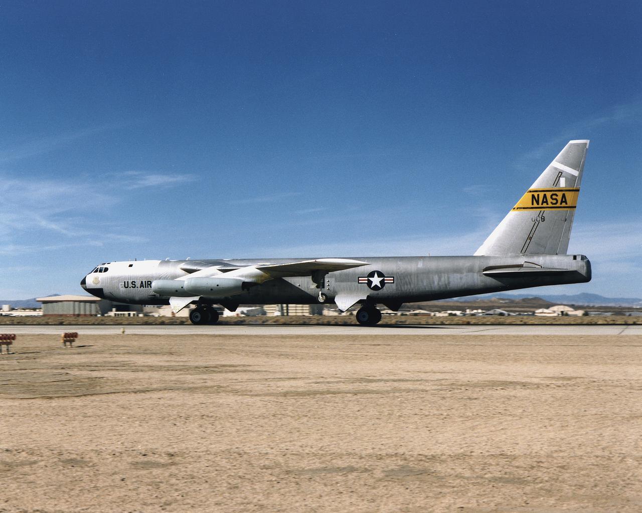
Dryden B-52 Launch Aircraft on Edwards AFB Runway
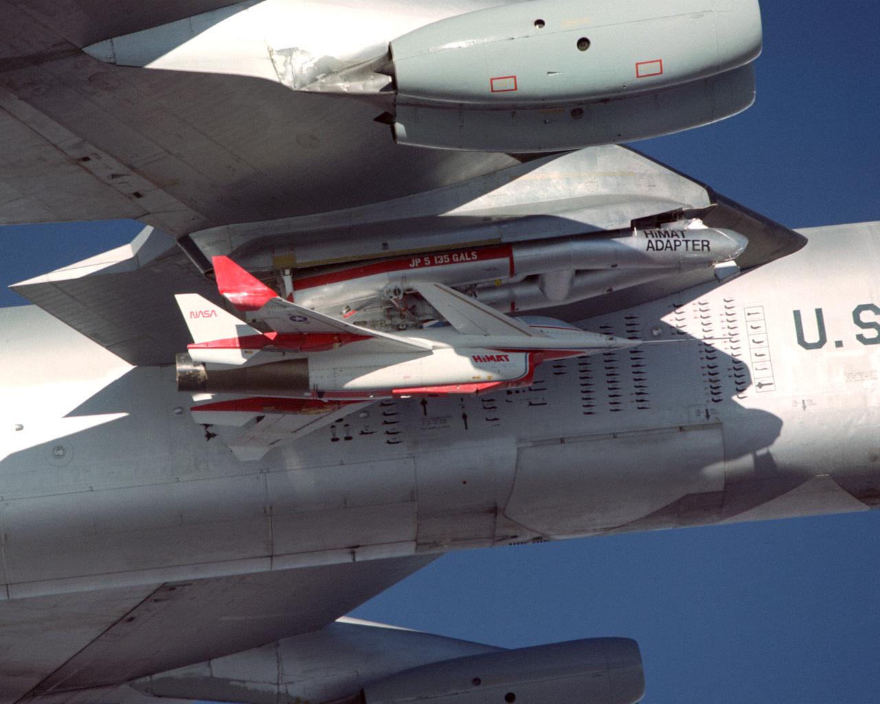
A close-up view of the Highly Maneuverable Aircraft Technology (HiMAT) research vehicle attached to a wing pylon on NASA’s B-52 mothership during a 1980 test flight. The HiMAT used sharply swept-back wings and a canard configuration to test possible technology for advanced fighters.
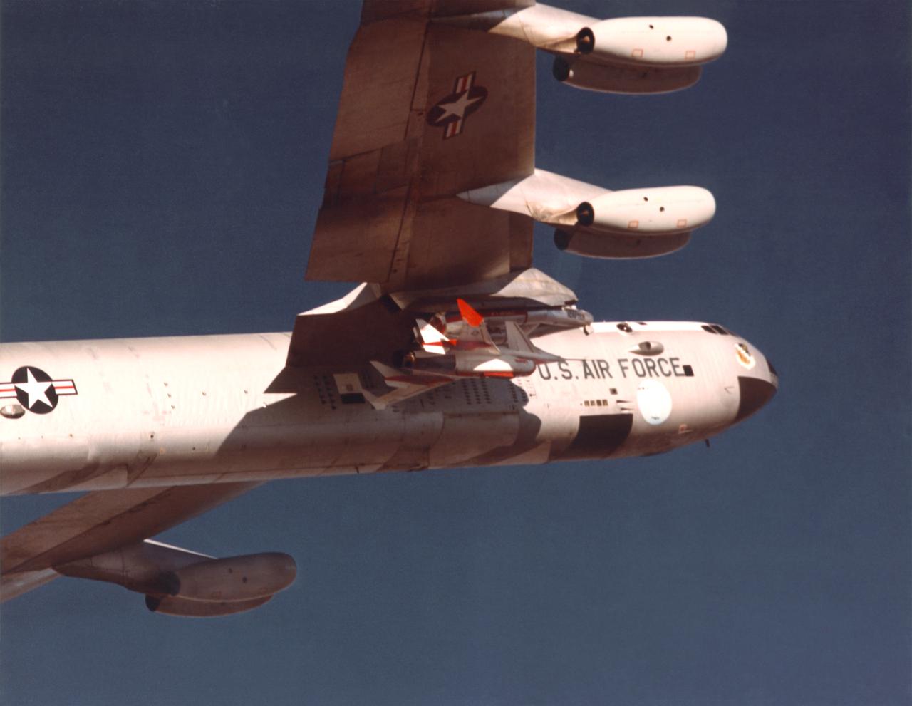
The Highly Maneuverable Aircraft Technology (HiMAT) research vehicle is shown here mated to a wing pylon on NASA’s B-52 mothership aircraft. The HiMAT was a technology demonstrator to test structures and configurations for advanced fighter concepts. Over the course of more than 40 years, the B-52 proved a valuable workhorse for NASA’s Dryden Flight Research Center (under various names), launching a wide variety of vehicles and conducting numerous other research flights.
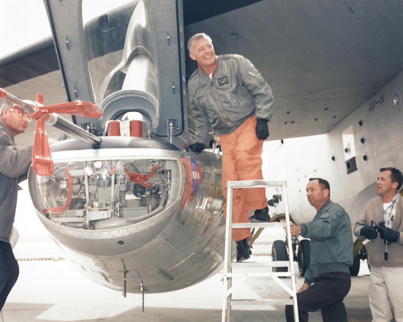
NASA research pilot Milt Thompson is helped into the cockpit of the M2-F2 lifting body research aircraft at NASA’s Flight Research Center (now the Dryden Flight Research Center). The M2-F2 is attached to a wing pylon under the wing of NASA’s B-52 mothership. The flight was a captive flight with the pilot on-board. Milt Thompson flew in the lifting body throughout the flight, but it was never dropped from the mothership.
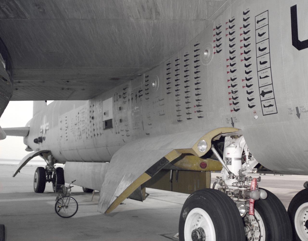
B-52 Flight Mission Symbology on Side of Craft
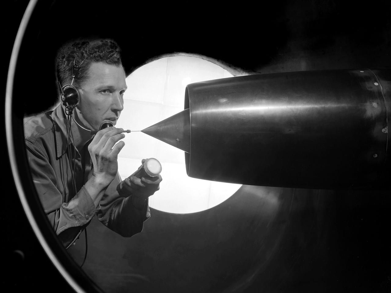
A technician at the National Advisory Committee for Aeronautics (NACA) Lewis Flight Propulsion Laboratory cleans the pitot tube on a 16-inch diameter ramjet in the 8- by 6-Foot Supersonic Wind Tunnel. Pitot tubes are a measurement device used to determine the flow velocity at a specific location in the air stream, not the average velocity of the entire wind stream. NACA Lewis was in the midst of a multi-year program to determine the feasibility of ramjets and design improvements that could be employed for all models. The advantage of the ramjet was its ability to process large volumes of combustion air, resulting in the burning of fuel at the optimal stoichiometric temperatures. This was not possible with turbojets. The higher the Mach number, the more efficient the ramjet operated. The 8- by 6 Supersonic Wind Tunnel had been in operation for just over one year when this photograph was taken. The facility was the NACA’s largest supersonic tunnel and the only facility capable of running an engine at supersonic speeds. The 8- by 6 tunnel was also equipped with a Schlieren camera system that captured the air flow gradient as it passes over the test setup. The ramjet tests in the 8- by 6 tunnel complemented the NACA Lewis investigations using aircraft, the Altitude Wind Tunnel and smaller supersonic tunnels. Researchers studied the ramjet’s performance at different speeds and varying angles -of -attack.

An inlet duct lowered into the 20-foot diameter test section of the Altitude Wind Tunnel at the National Advisory Committee for Aeronautics (NACA) Lewis Flight Propulsion Laboratory. Engines and hardware were prepared in the facility’s shop area. The test articles were lifted by a two-rail Shaw box crane through the high-bay and the second-story test chamber before being lowered into the test section. Technicians then spent days or weeks hooking up the supply lines and data recording telemetry. The engines were mounted on wingspans that stretched across the test section. The wingtips attached to the balance frame’s trunnions, which could adjust the angle of attack. The balance frame included six devices that recorded data and controlled the engine. The measurements were visible in banks of manometer boards next to the control room. Photographs recorded the pressure levels in the manometer tubes, and the computing staff manually converted the data into useful measurements. A mechanical pulley system was used to raise and lower the tunnel’s large clamshell lid into place. The lid was sealed into place using hand-turned locks accessible from the viewing platform. The lid had viewing windows above and below the test article, which permitted the filming and visual inspection of the tests.
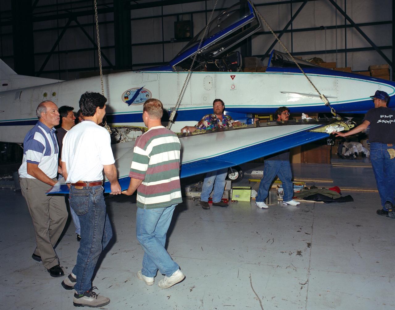
U.S. and German personnel of the X-31 Enhanced Fighter Maneuverability Technology Demonstrator aircraft program removing the right wing of the aircraft, which was ferried from Edwards Air Force Base, California, to Europe on May 22, 1995 aboard an Air Force Reserve C-5 transport. The X-31, based at the NASA Dryden Flight Research Center was ferried to Europe and flown in the Paris Air Show in June. The wing of the X-31 was removed on May 18, 1995, to allow the aircraft to fit inside the C-5 fuselage. Officials of the X-31 project used Manching, Germany, as a staging base to prepare the aircraft for the flight demonstration. At the air show, the X-31 demonstrated the value of using thrust vectoring (directing engine exhaust flow) coupled with advanced flight control systems to provide controlled flight at very high angles of attack. The aircraft arrived back at Edwards in a Air Force Reserve C-5 on June 25, 1995 and off loaded at Dryden June 27. The X-31 aircraft was developed jointly by Rockwell International's North American Aircraft Division (now part of Boeing) and Daimler-Benz Aerospace (formerly Messerschmitt-Bolkow-Blohm), under sponsorship by the U.S. Department of Defense and the German Federal Ministry of Defense.
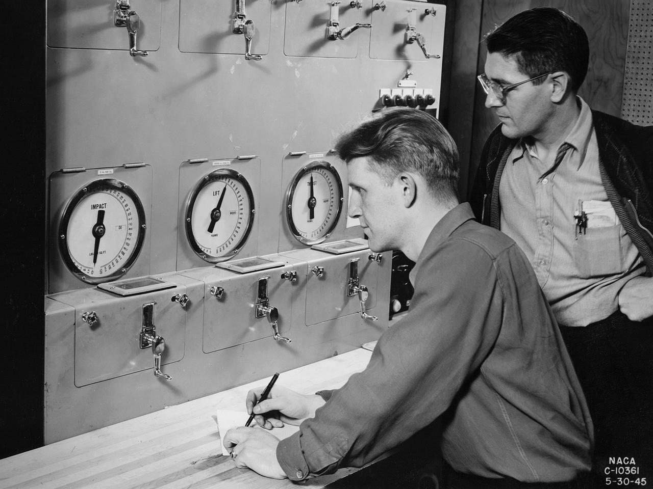
Researchers at the National Advisory Committee for Aeronautics (NACA) Aircraft Engine Research Laboratory monitor a ramjet's performance in the Altitude Wind Tunnel from the control room. The soundproof control room was just a few feet from the tunnel’s 20-foot-diameter test section. In the control room, the operators could control all aspects of the tunnel’s operation, including the air density, temperature, and speed. They also operated the engine or test article in the test section by controlling the angle-of-attack, speed, power, and other parameters. The men in this photograph are monitoring the engine’s thrust and lift. A NACA-designed 20-inch-diameter ramjet was installed in the tunnel in May 1945. Thrust figures from these runs were compared with drag data from tests of scale models in small supersonic tunnels to verify the ramjet’s feasibility. The tunnel was used to analyze the ramjet’s overall performance up to altitudes of 47,000 feet and speeds to Mach 1.84. The researchers found that an increase in altitude caused a reduction in the engine’s horsepower and identified optimal flameholder configurations.
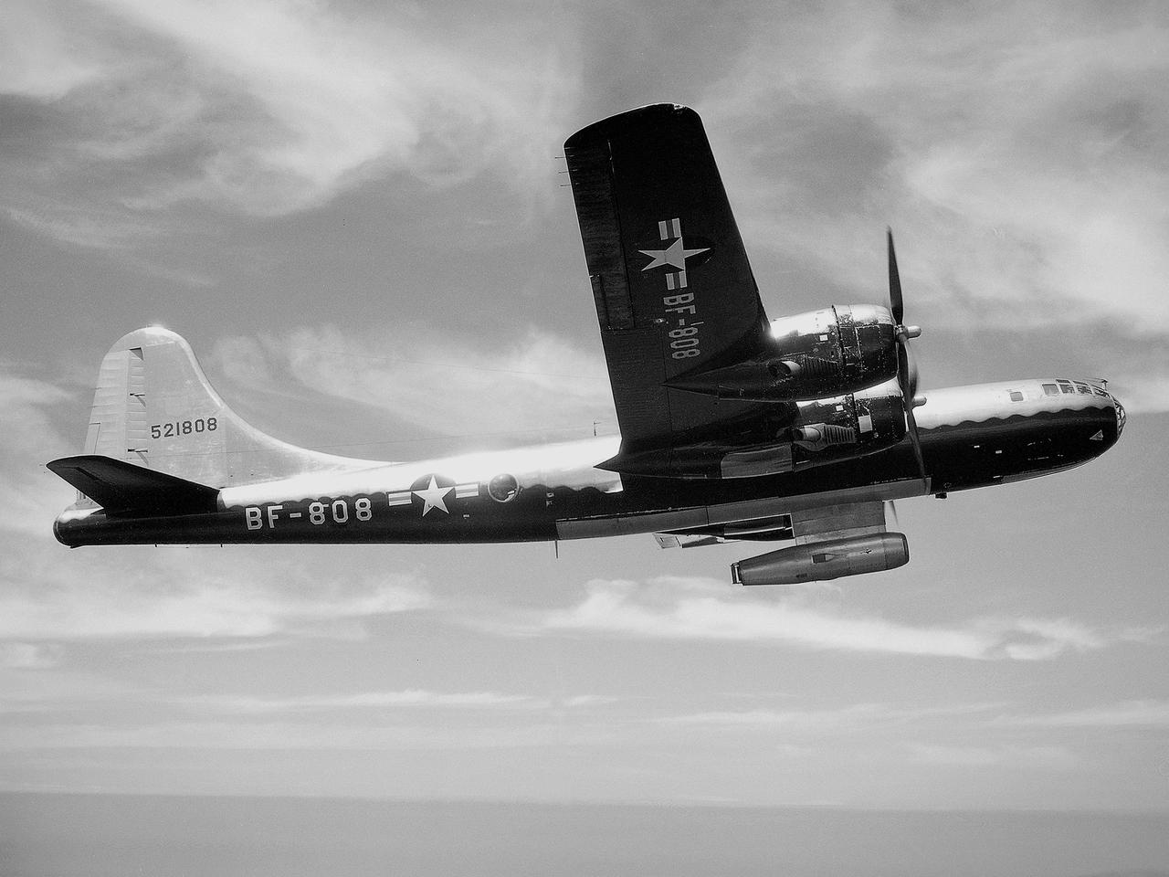
The NACA’s Lewis Flight Propulsion Laboratory used a Boeing B‒29 Superfortress as a testbed for ramjet investigations in the late 1940s. Lewis researchers conducted a wide variety of studies on ramjets to determine basic the operational data necessary to design missiles. Extensive wind tunnel and test stand studies were augmented by actual flight tests. Lewis engineers modified this B‒29 so that the ramjet could be stored in the bomb bay. Once the aircraft reached the desired altitude and speed, a mechanical arm suspended the ramjet 52 inches below the bomb bay. The ramjet’s angle-of-attack could be independently adjusted, and a periscope permitted a view of the test article from inside the aircraft. Researchers took measurements in free-stream conditions at speeds up to Mach 0.51 and at altitudes ranging from 5,000 to 30,000 feet. They then shut the ramjet down and retracted it into the aircraft. The researchers first determined that 14,000 feet was the maximum altitude at which the engine could be ignited by spark. They used flares to start the engine at altitudes up to 30,000 feet. They were able to determine maximum combustion efficiencies, response time to changes in fuel flow, and minimum fuel-air ratios. Overall the ramjet operated well at all speeds and altitudes.
The right wing of the X-31 Enhanced Fighter Maneuverability Technology Demonstrator Aircraft is seen here being put into a shipping container May 18, 1995, at NASA's Dryden Flight Research Center, Edwards, California, by U.S. and German members of the program. To fit inside an Air Force Reserve C-5 transport, which was used to ferry the X-31 to Europe on May 22, 1995, the right wing had to be removed. Manching, Germany, was used as a staging base to prepare the aircraft for participation in the Paris Air Show. At the air show on June 11 through the 18th, the X-31 demonstrated the value of using thrust vectoring (directing engine exhaust flow) coupled with advanced flight control systems to provide controlled flight at very high angles of attack. The aircraft arrived back at Edwards in an Air Force Reserve C-5 on June 25, 1995, and off loaded at Dryden the 27th. The X-31 aircraft was developed jointly by Rockwell International's North American Aircraft Division (now part of Boeing) and Daimler-Benz Aerospace (formerly Messerschmitt-Bolkow-Blohm), under sponsorship by the U.S. Department of Defense and the German Federal Ministry of Defense.
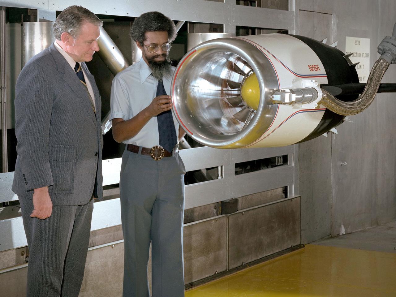
Center Director John McCarthy, left, and researcher Al Johns pose with a one-third scale model of a Grumman Aerospace tilt engine nacelle for Vertical and Short Takeoff and Landing (V/STOL) in the 9- by 15-Foot Low Speed Wind Tunnel at the National Aeronautics and Space Administration (NASA) Lewis Research Center. Lewis researchers had been studying tilt nacelle and inlet issues for several years. One area of concern was the inlet flow separation during the transition from horizontal to vertical flight. The separation of air flow from the inlet’s internal components could significantly stress the fan blades or cause a loss of thrust. In 1978 NASA researchers Robert Williams and Al Johns teamed with Grumman’s H.C. Potonides to develop a series of tests in the Lewis 9- by 15-foot tunnel to study a device designed to delay the flow separation by blowing additional air into the inlet. A jet of air, supplied through the hose on the right, was blown over the inlet surfaces. The researchers verified that the air jet slowed the flow separation. They found that the blowing on boundary layer control resulted in a doubling of the angle-of-attack and decreases in compressor blade stresses and fan distortion. The tests were the first time the concept of blowing air for boundary layer control was demonstrated. Boundary layer control devices like this could result in smaller and lighter V/STOL inlets.
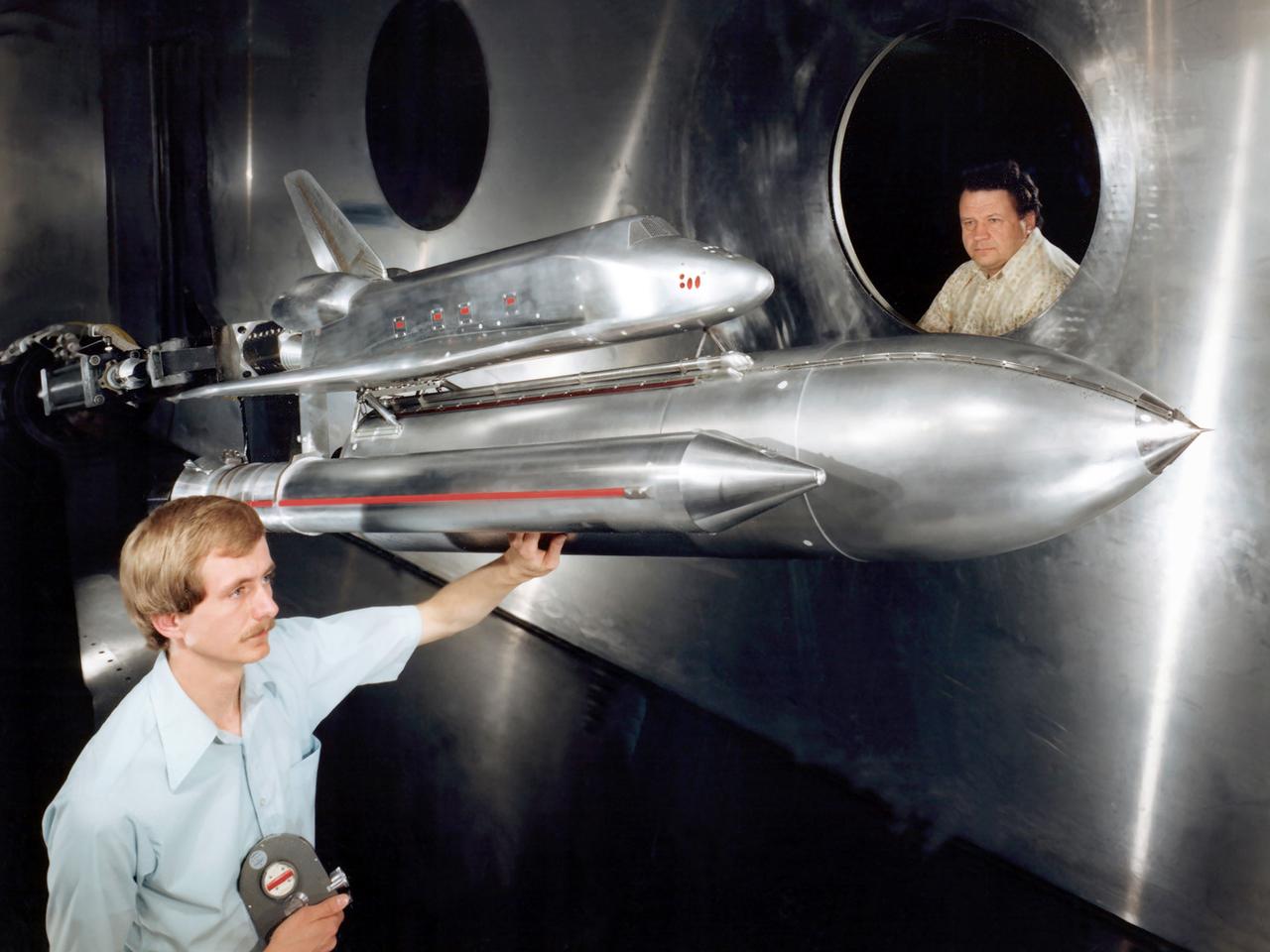
Technicians examine a scale model of the space shuttle used to obtain pressure data during tests in the 10- by 10-Foot Supersonic Wind Tunnel at the National Aeronautics and Space Administration (NASA) Lewis Research Center. Lewis researchers used the 10- by 10 tunnel extensively in the 1970s to study shuttle configurations in order to forecast conditions during an actual flight. These tests included analysis of the solid rocket boosters’ aerodynamics, orbiter forebody angle -of -attack and air speed, base heating for entire shuttle, and engine-out loads. The test seen in this photograph used a 3.5- percent scale aluminum alloy model of the entire launch configuration. The program was designed to obtain aerodynamic pressure data. The tests were part of a larger program to study possible trouble areas for the shuttle’s new Advanced Flexible Reusable Surface Insulation. The researchers obtained aeroacoustic data and pressure distributions from five locations on the model. Over 100 high-temperature pressure transducers were attached to the model. Other portions of the test program were conducted at Lewis’ 8- by 6-Foot Supersonic Wind Tunnel and the 11- by 11-Foot Transonic Wind Tunnel at Ames Research Center.
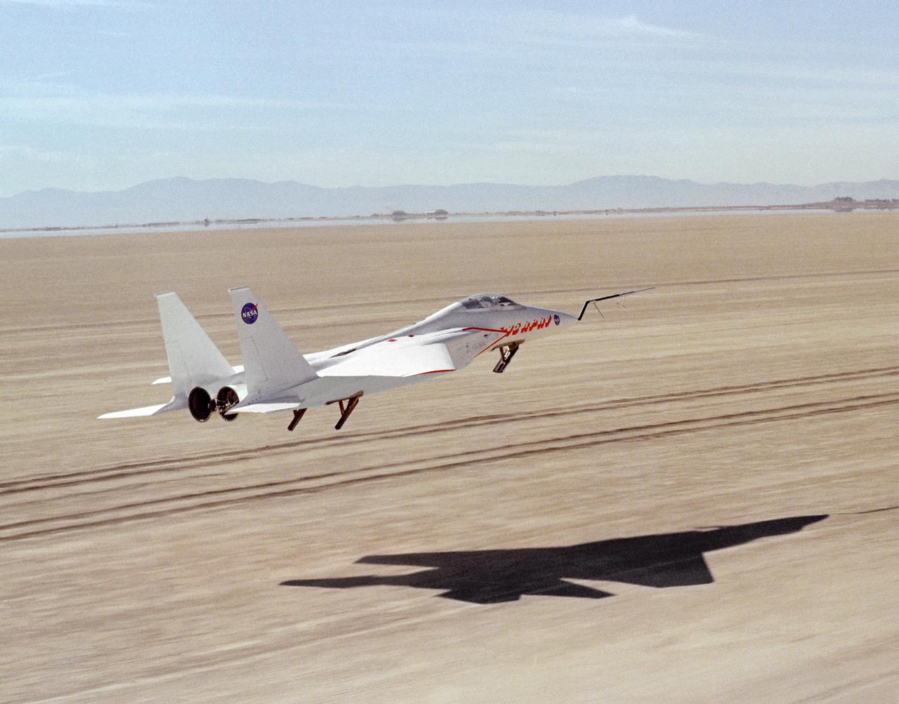
This photograph shows NASA's 3/8th-scale remotely piloted research vehicle landing on Rogers Dry Lakebed at Edwards Air Force Base, California, in 1975.
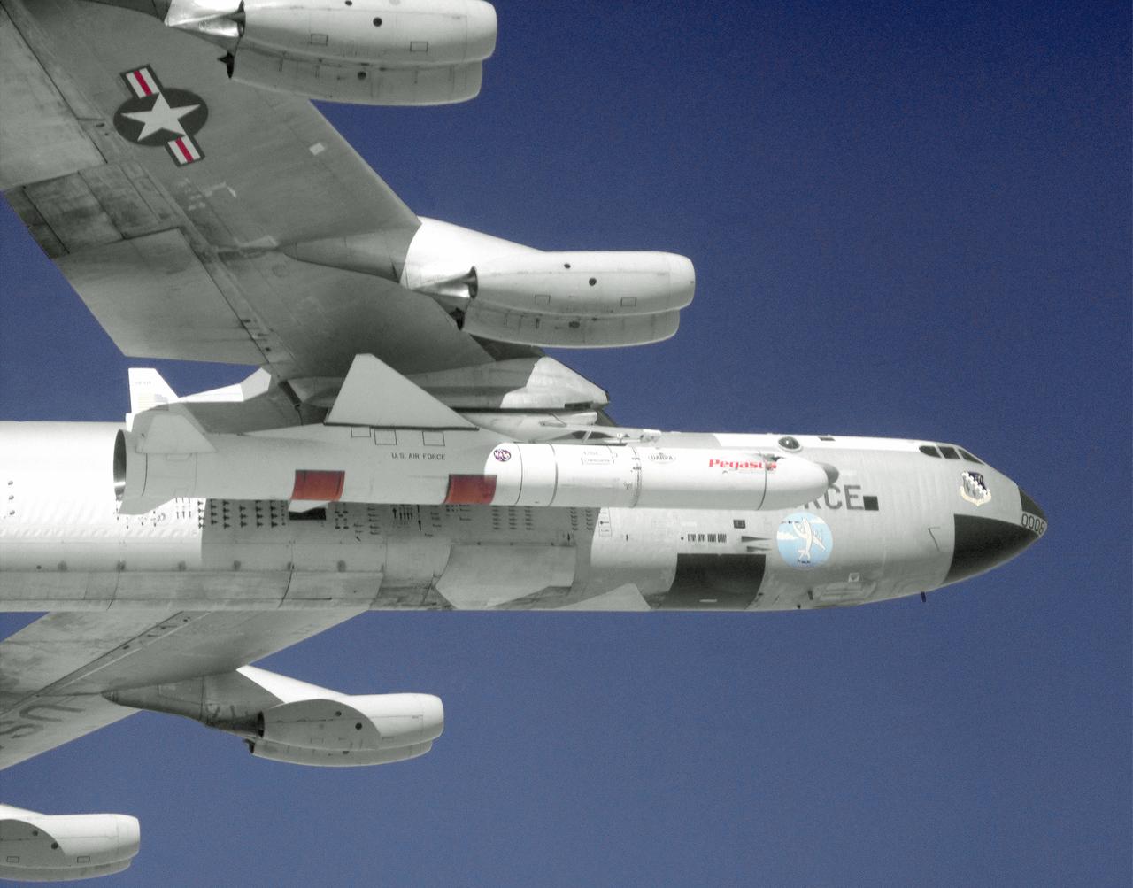
The Pegasus air-launched space booster is carried aloft under the right wing of NASA's B-52 carrier aircraft on its first captive flight from the Dryden Flight Research Center, Edwards, California. The first of two scheduled captive flights was completed on November 9, 1989. Pegasus is used to launch satellites into low-earth orbits cheaply. In 1997, a Pegasus rocket booster was also modified to test a hypersonic experiment (PHYSX). An experimental "glove," installed on a section of its wing, housed hundreds of temperature and pressure sensors that sent hypersonic flight data to ground tracking facilities during the experiment’s flight.
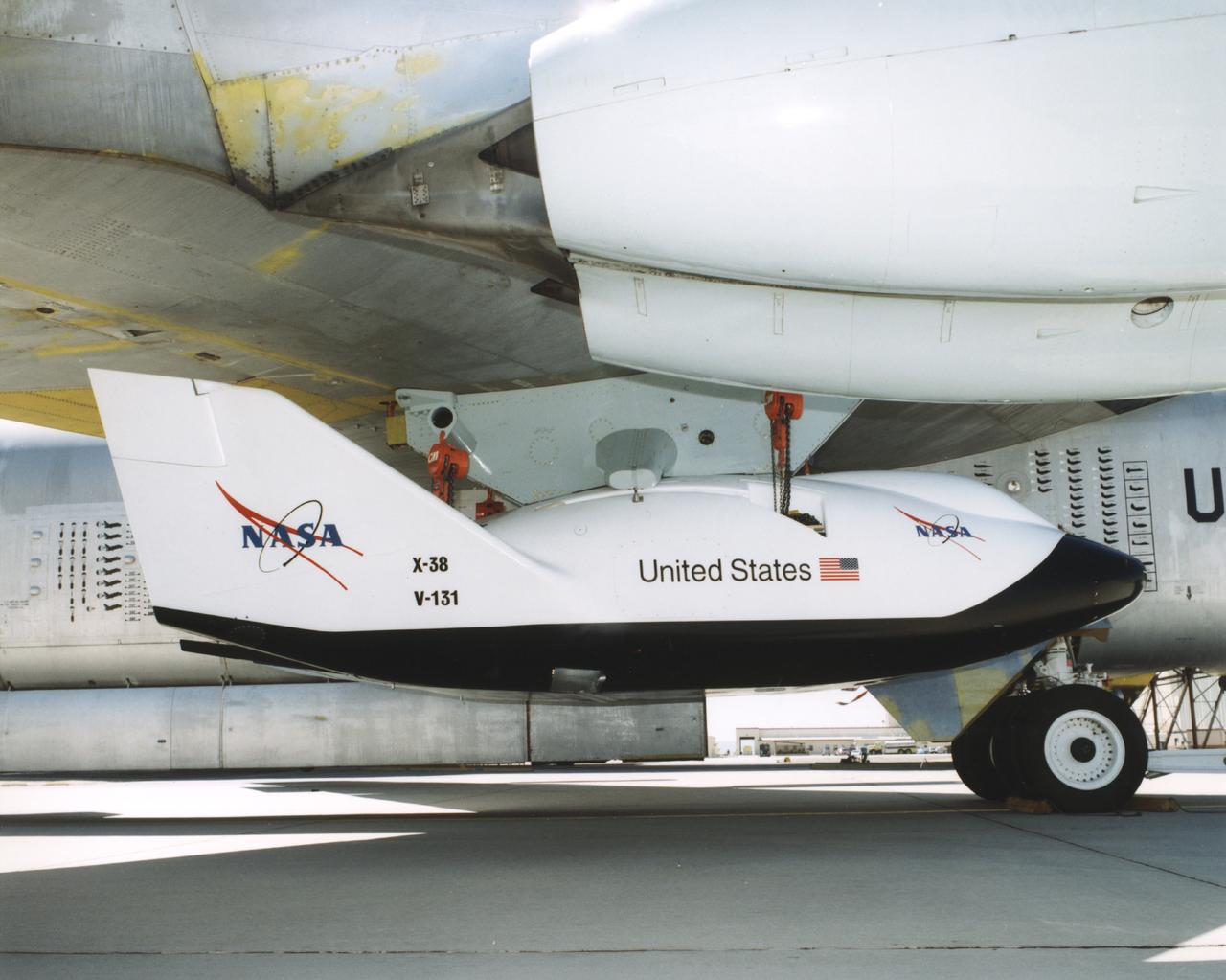
A close-up view of the X-38 research vehicle mounted under the wing of the B-52 mothership prior to a 1997 test flight. The X-38, which was designed to help develop technology for an emergency crew return vehicle (CRV) for the International Space Station, is one of many research vehicles the B-52 has carried aloft over the past 40 years.
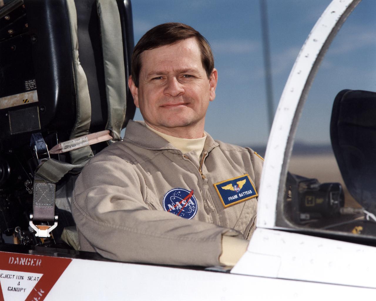
Frank Batteas is a research test pilot in the Flight Crew Branch of NASA's Dryden Flight Research Center, Edwards, California. He is currently a project pilot for the F/A-18 and C-17 flight research projects. In addition, his flying duties include operation of the DC-8 Flying Laboratory in the Airborne Science program, and piloting the B-52B launch aircraft, the King Air, and the T-34C support aircraft. Batteas has accumulated more than 4,700 hours of military and civilian flight experience in more than 40 different aircraft types. Batteas came to NASA Dryden in April 1998, following a career in the U.S. Air Force. His last assignment was at Wright-Patterson Air Force Base, Dayton, Ohio, where Lieutenant Colonel Batteas led the B-2 Systems Test and Evaluation efforts for a two-year period. Batteas graduated from Class 88A of the Air Force Test Pilot School, Edwards Air Force Base, California, in December 1988. He served more than five years as a test pilot for the Air Force's newest airlifter, the C-17, involved in nearly every phase of testing from flutter and high angle-of-attack tests to airdrop and air refueling envelope expansion. In the process, he achieved several C-17 firsts including the first day and night aerial refuelings, the first flight over the North Pole, and a payload-to-altitude world aviation record. As a KC-135 test pilot, he also was involved in aerial refueling certification tests on a number of other Air Force aircraft. Batteas received his commission as a second lieutenant in the U. S. Air Force through the Reserve Officer Training Corps and served initially as an engineer working on the Peacekeeper and Minuteman missile programs at the Ballistic Missile Office, Norton Air Force Base, Calif. After attending pilot training at Williams Air Force Base, Phoenix, Ariz., he flew operational flights in the KC-135 tanker aircraft and then was assigned to research flying at the 4950th Test Wing, Wright-Patterson. He flew extensively modified C-135
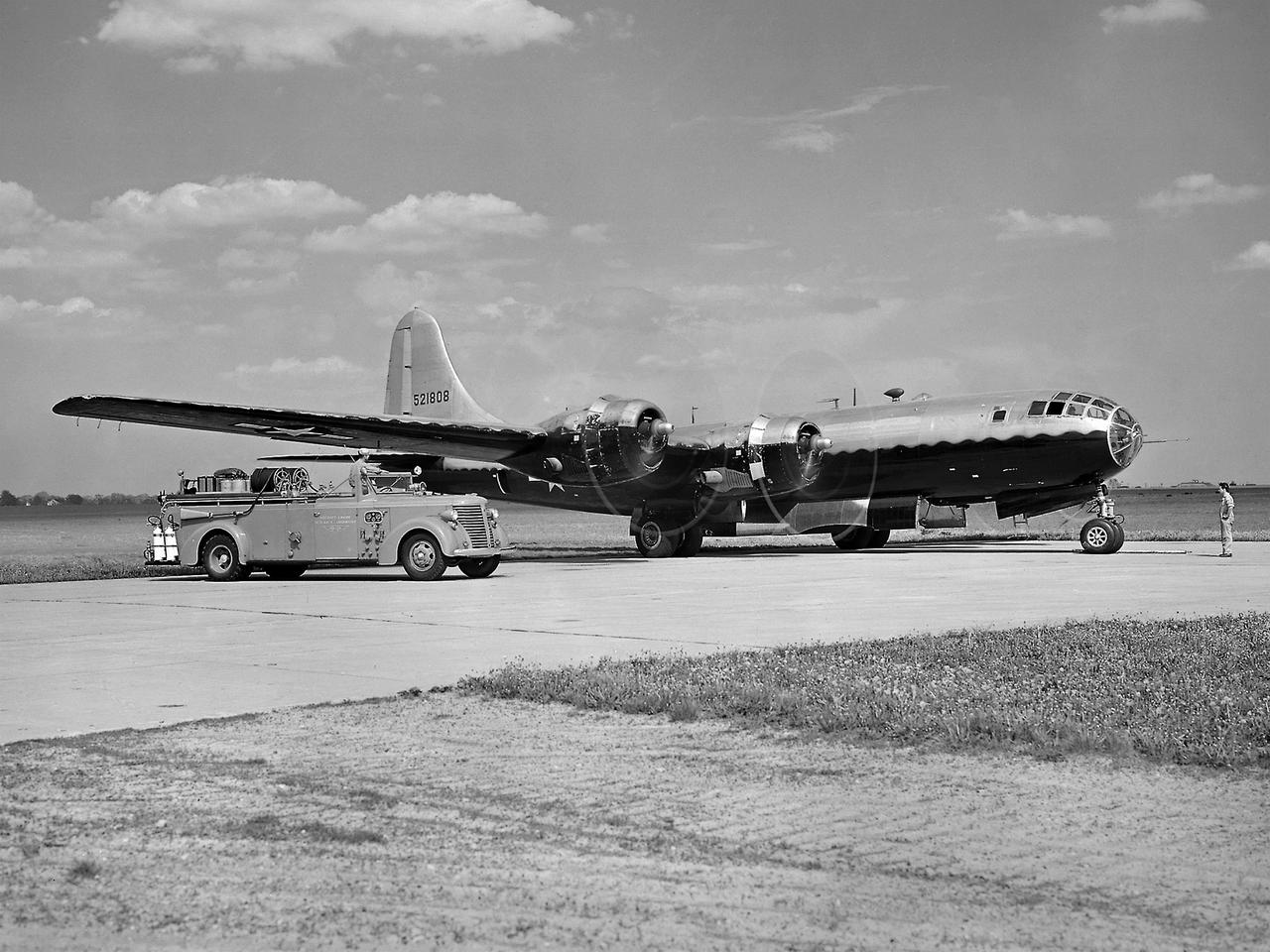
The NACA’s Lewis Flight Propulsion Laboratory used a Boeing B-29 Superfortress as a testbed for ramjet investigations in the late 1940s. NACA Lewis conducted a wide variety of studies on ramjets to determine basic operational data necessary to design missiles. This information included the relationship between combustion chamber and inlet pressure and temperature, velocity of the fuel-air ratio to the ignition characteristics, and combustion efficiency. Although wind tunnel and test stand studies were important first steps in determining these factors, actual flight tests were required. Lewis engineers modified the B-29 so that the ramjet could be stored in the bomb bay. Once the aircraft reached the desired altitude and speed the ramjet was suspended 52 inches below the bomb bay. The ramjet’s angle-of-attack could be independently adjusted, and a periscope permitted a view of the test article from inside the aircraft. Measurements were taken in free-stream conditions between 5,000 and 30,000 feet. The test flights, which began in April 1947, were flown at speeds up to Mach 0.51 and altitudes of 5,000 to 30,000 feet. The researchers first determined that 14,000 feet was the maximum altitude at which the engine could be ignited by spark. Flares were used to start the engine at altitudes up to 30,000 feet. Overall the ramjet operated well at all speeds and altitudes. Significant changes in fuel flow were successful at lower altitudes, but produced combustion blowout above 20,000 feet.
A technician checks a 0.25-scale engine model of a Vought Corporation V-530 engine in the test section of the 10- by 10-Foot Supersonic Wind Tunnel at the National Aeronautics and Space Administration (NASA) Lewis Research Center. Vought created a low-drag tandem-fan Vertical/Short and Takeoff and Landing (V/STOL) engine in the mid-1970s, designated as the V-530. The first fan on the tandem-fan engine was supplied with air through a traditional subsonic inlet, seen on the lower front of the engine. The air was exhausted through the nacelle during normal flight and directed down during takeoffs. The rear fan was supplied by the oval-shaped top inlet during all phases of the flight. The second fan exhausted its air through a rear vectorable nozzle. NASA Lewis and Vought partnered in the late 1970s to collect an array of inlet and nozzle design information on the tandem fan engines for the Navy. Vought created this .25-scale model of the V-530 for extensive testing in Lewis' 10- by 10-foot tunnel. During an early series of tests, the front fan was covered, and a turbofan simulator was used to supply air to the rear fan. The researchers then analyzed the performance of only the front fan inlet. During the final series of tests, the flow from the front fan was used to supply airflow to the rear fan. The researchers studied the inlet's recovery, distortion, and angle-of-attack limits over various flight conditions.
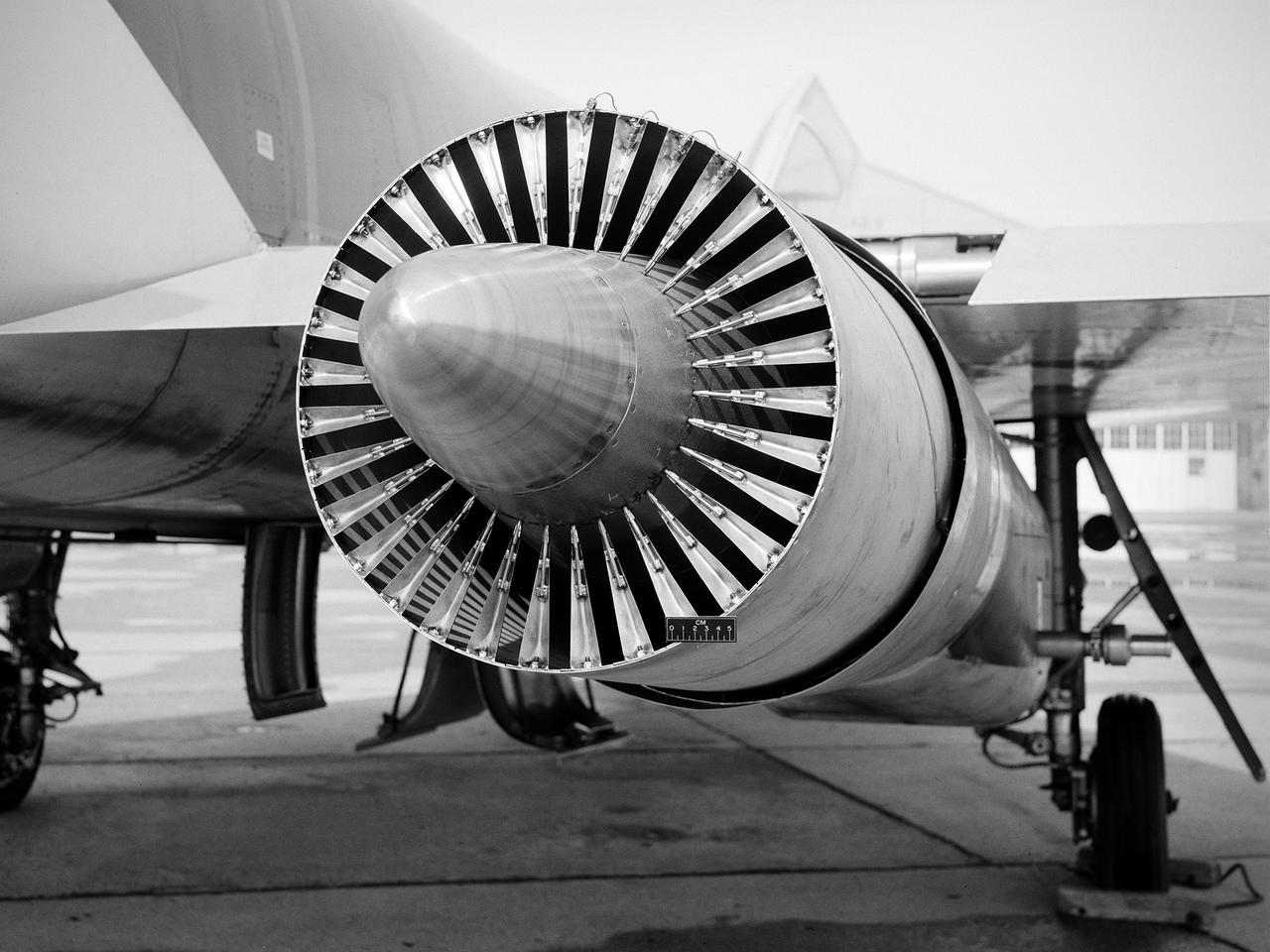
National Aeronautics and Space Administration (NASA) Convair F-106B Delta Dart with a 32-spoke nozzle installed on its General Electric J85 test engine. Lewis acquired a Delta Dart fighter in 1966 to study the components for propulsion systems that could be applied to supersonic transport aircraft at transonic speeds. The F-106B was modified with two General Electric J85-13 engines under its wings to study these components. The original test plan was expanded to include the study of boattail drag, noise reduction, and inlets. From February to July 1971 the modified F-106B was used to study different ejector nozzles. Researchers conducted both acoustic and aerodynamic tests on the ground and in flight. Several models were created to test different suppression methods. NASA Lewis’ conical nozzle was used as the baseline configuration. Flightline and sideline microphones were set up on the ground. The F-106B would idle its own engine and buzz the recording station from an altitude of 300 feet at Mach 0.4 with the test engines firing. Researchers found that the suppression of the perceived noise level was usually lower during flight than the researchers had statistically predicted. The 64 and 32-spoke nozzles performed well in actual flight, but the others nozzles tended to negatively affect the engine’s performance. Different speeds or angles- -of-attack sometimes changed the noise levels. In the end, no general conclusions could be applied to all the nozzles.
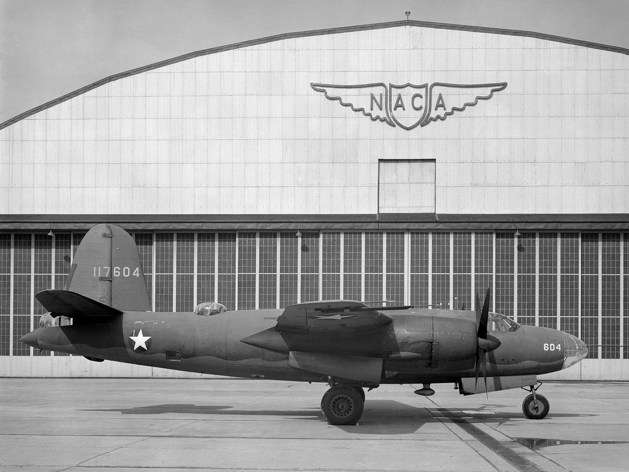
The Aircraft Engine Research Laboratory’s first aircraft, a Martin B–26B Marauder, parked in front of the Flight Research Building in September 1943. The military loaned the B–26B to the National Advisory Committee for Aeronautics (NACA) to augment the lab’s studies of the Wright Aeronautical R–2800 engines. The military wanted to improve the engine cooling in order to increase the bomber’s performance. On March 17, 1943, the B–26B performed the very first research flight at the NACA’s new engine laboratory. The B–26B received its “Widowmaker” nickname during the rushed effort to transition the new aircraft from design to production and into the sky. During World War II, however, the B–26B proved itself to be a capable war machine. The U.S. lost fewer Marauders than any other type of bomber employed in the war. The B–26B was originally utilized at low altitudes in the Pacific but had its most success at high altitudes over Europe. The B–26B’s flight tests in Cleveland during 1943 mapped the R-2800 engine’s behavior at different altitudes and speeds. The researchers were then able to correlate engine performance in ground facilities to expected performance at different altitudes. They found that air speed, cowl flap position, angle of attack, propeller thrust, and propeller speed influenced inlet pressure recovery and exhaust distribution. The flight testing proceeded quickly, and the B–26B was transferred elsewhere in October 1943.