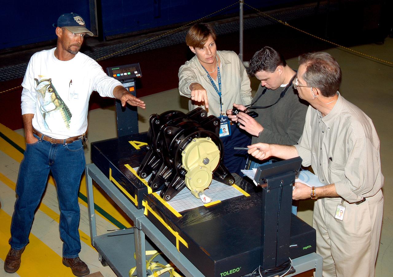
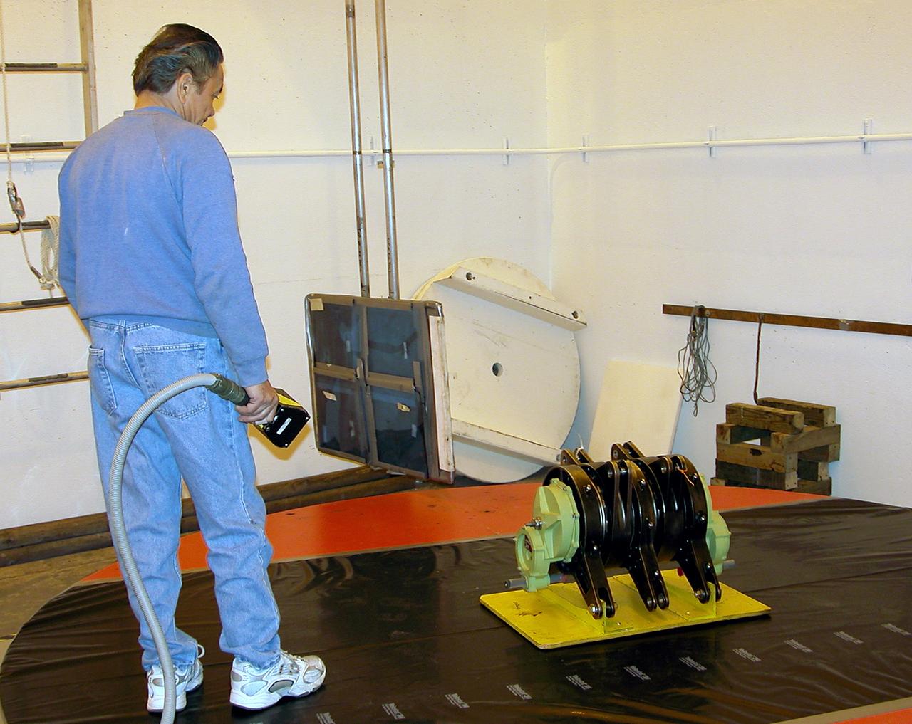
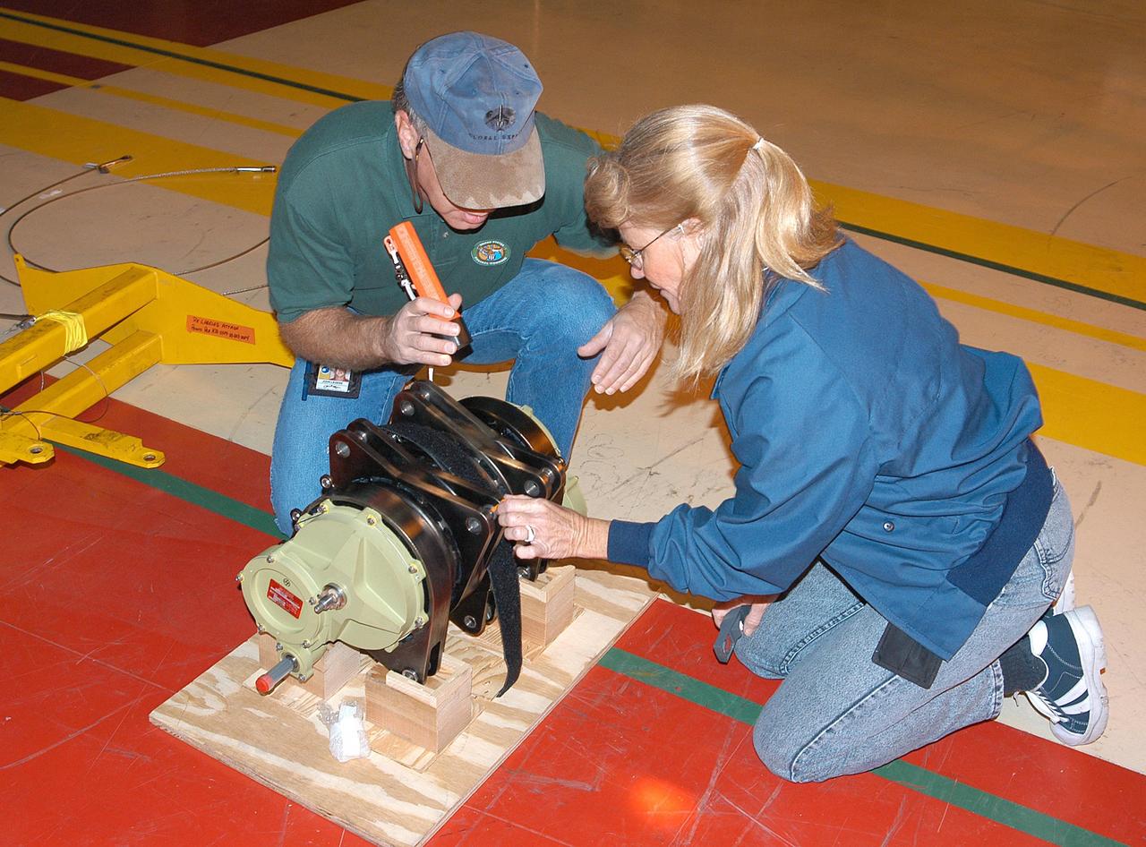
KENNEDY SPACE CENTER, FLA. - Workers in the Orbiter Processing Facility measure the alignment of bearings on a rudder speed brake actuator. Actuators move an orbiter’s rudder, speed brake, elevons and main engines during flight.
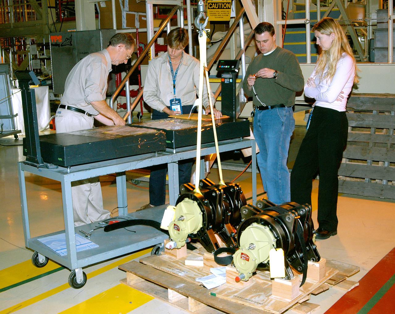
KENNEDY SPACE CENTER, FLA. - Workers in the Orbiter Processing Facility get ready to measure the alignment of the bearings on the rudder speed brake actuators sitting on the floor in the foreground. The actuators move an orbiter’s rudder, speed brake, elevons and main engines during flight.
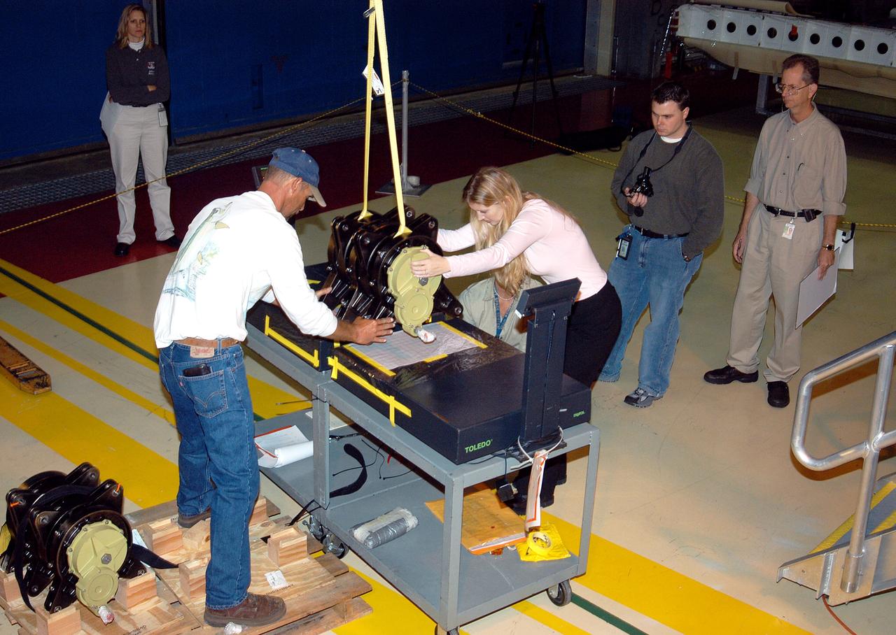
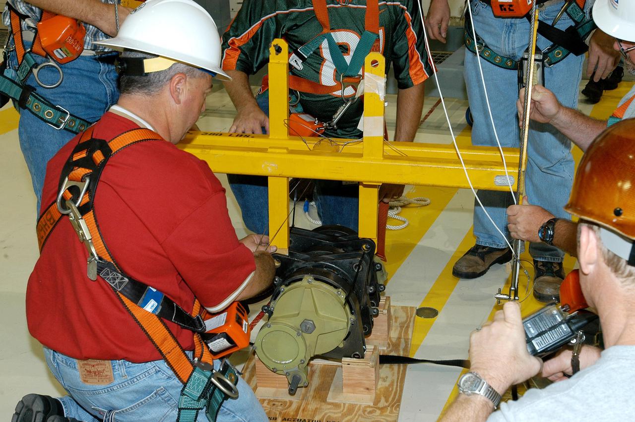
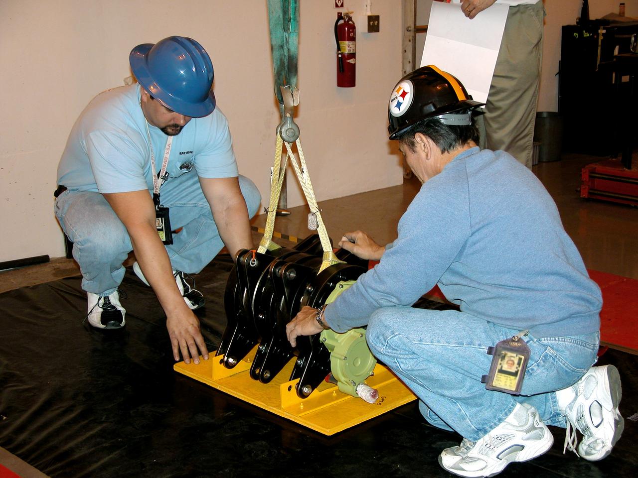
KENNEDY SPACE CENTER, FLA. - Workers in the Orbiter Processing Facility settle into place one of two rudder speed brake actuators onto a table to measure the alignment of its bearings. The actuators move an orbiter’s rudder, speed brake, elevons and main engines during flight.
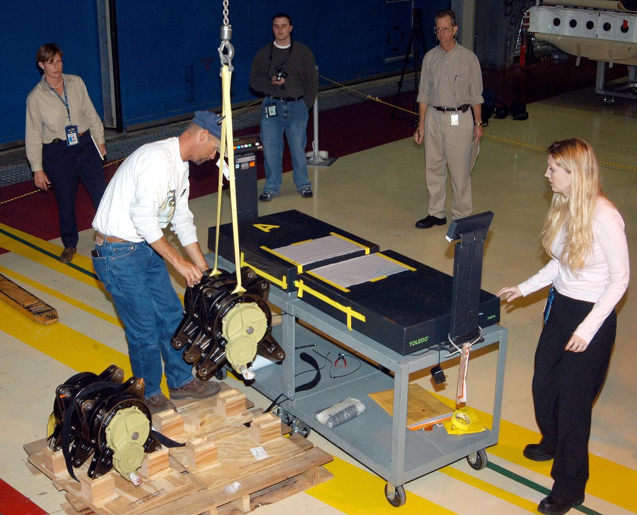
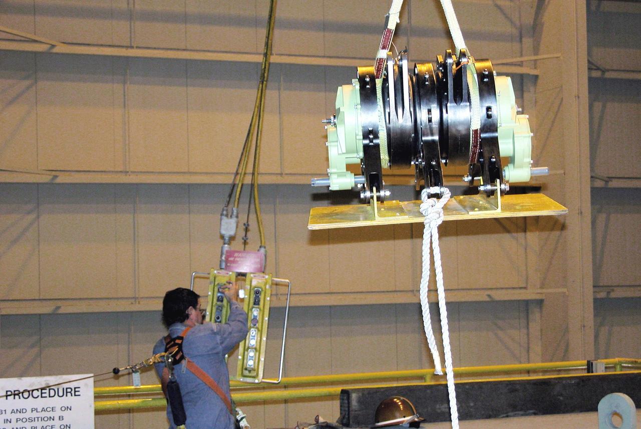
KENNEDY SPACE CENTER, FLA. - Workers in the Orbiter Processing Facility stand by while another guides the lifting of one of two rudder speed brake actuators onto a table to measure the alignment of its bearings. The actuators move an orbiter’s rudder, speed brake, elevons and main engines during flight.
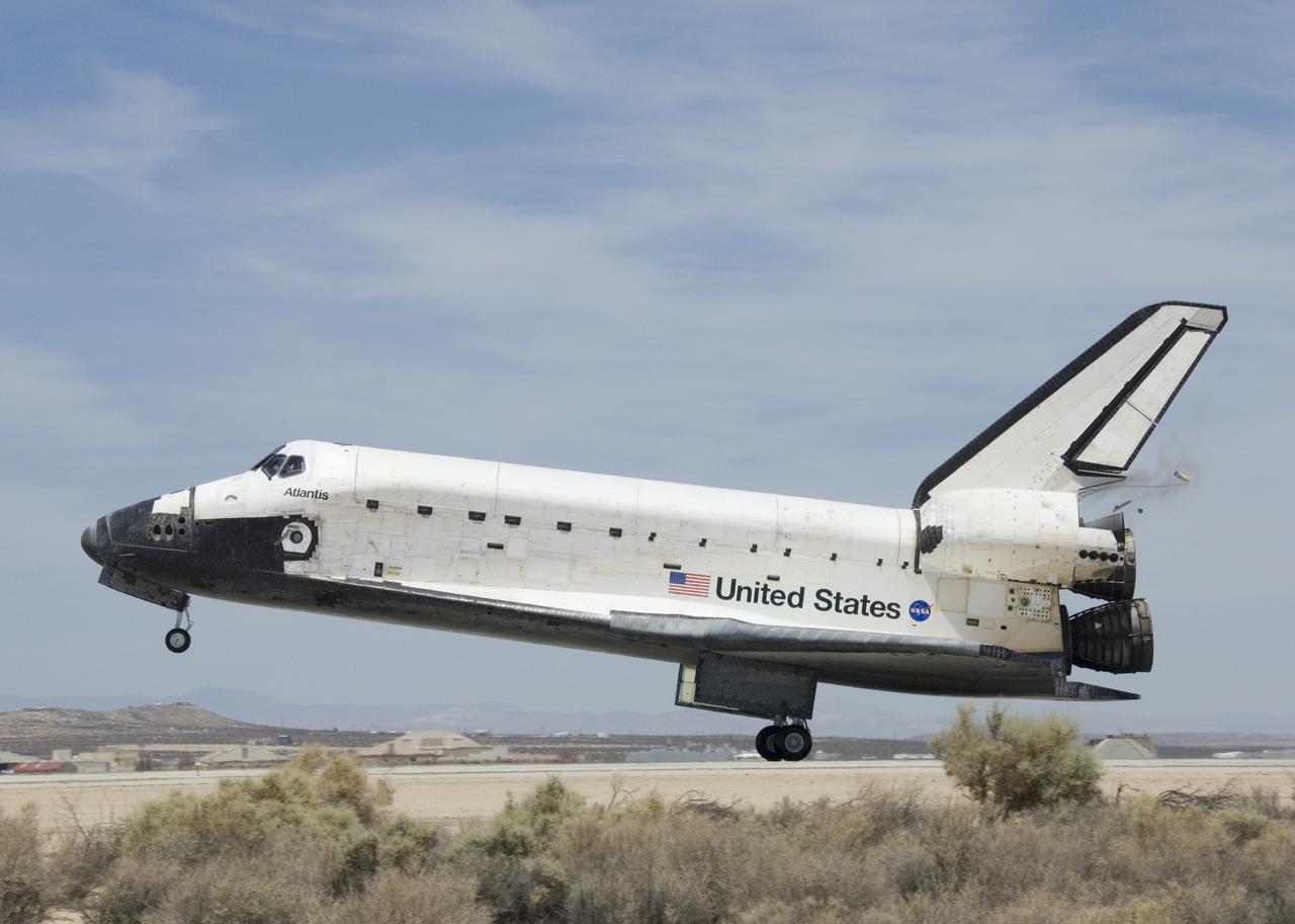
Space Shuttle Atlantis starts to deploy its braking parachute following touchdown at Edwards Air Force Base, California, on June 22, 2007.
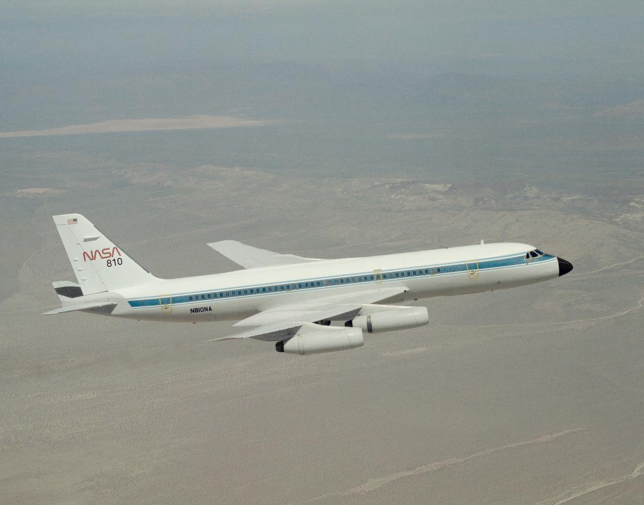
A NASA CV-990, modified as a Landing Systems Research Aircraft (LSRA), in flight over NASA's Dryden Flight Research Center, Edwards, California, for a test of the space shuttle landing gear system. The space shuttle landing gear test unit, operated by a high-pressure hydraulic system, allowed engineers to assess and document the performance of space shuttle main and nose landing gear systems, tires and wheel assemblies, plus braking and nose wheel steering performance. The series of 155 test missions for the space shuttle program provided extensive data about the life and endurance of the shuttle tire systems and helped raise the shuttle crosswind landing limits at Kennedy.
A NASA CV-990, modified as a Landing Systems Research Aircraft (LSRA), in flight over NASA's Dryden Flight Research Center, Edwards, California, for a test of the space shuttle landing gear system. The space shuttle landing gear test unit, operated by a high-pressure hydraulic system, allowed engineers to assess and document the performance of space shuttle main and nose landing gear systems, tires and wheel assemblies, plus braking and nose wheel steering performance. The series of 155 test missions for the space shuttle program provided extensive data about the life and endurance of the shuttle tire systems and helped raise the shuttle crosswind landing limits at Kennedy.
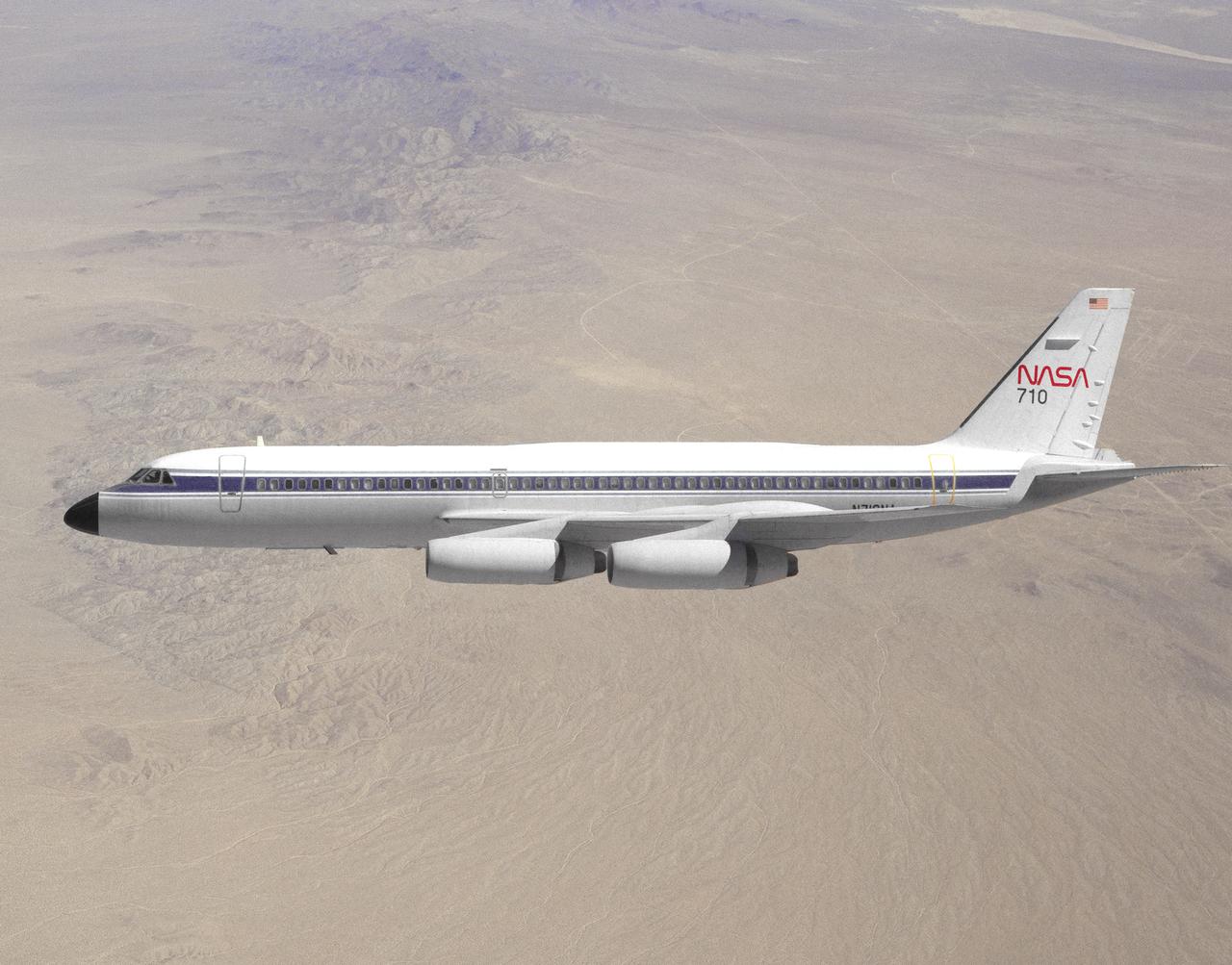
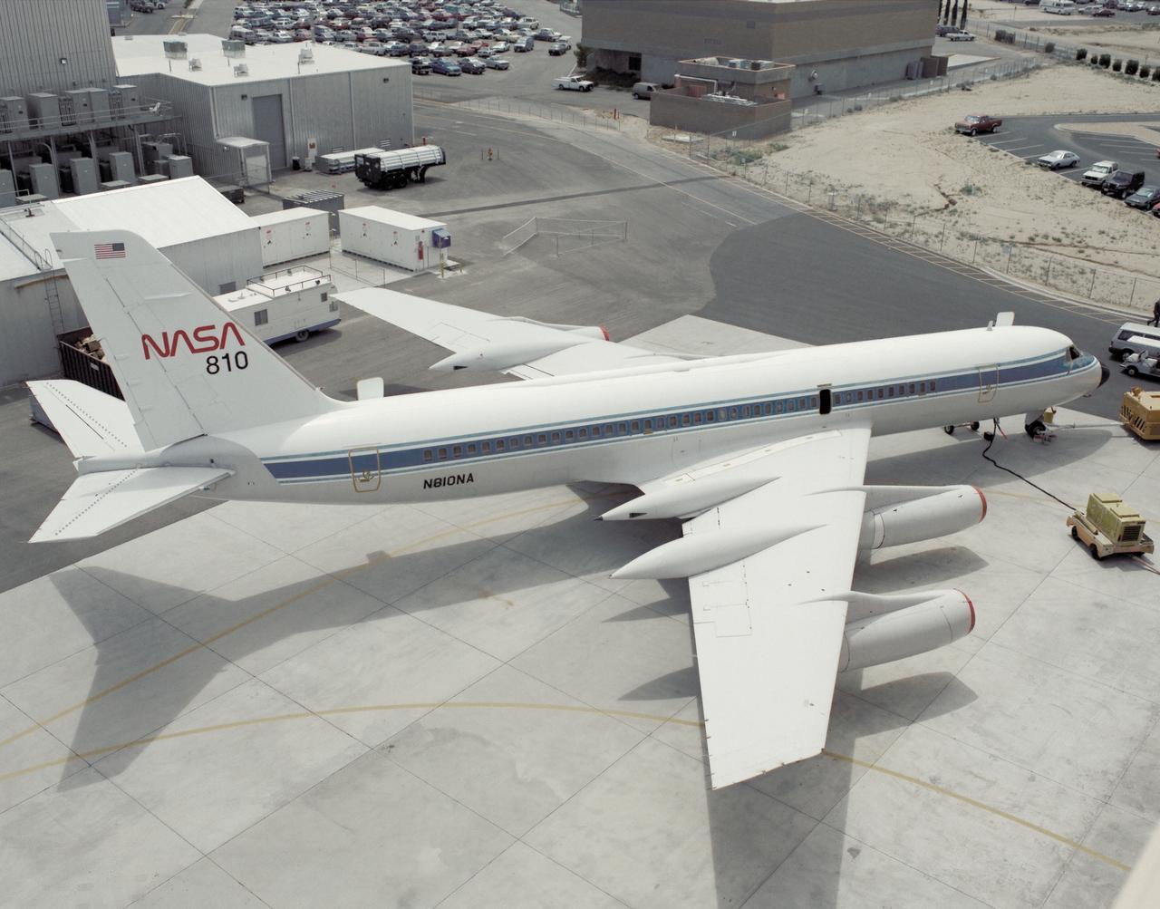
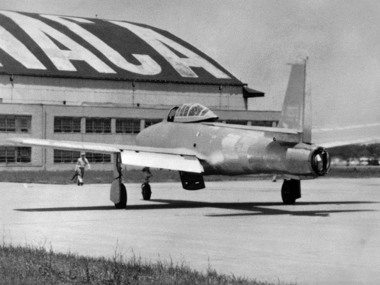
NASA 710, a Convair 990 transport aircraft formerly used for medium altitude atmospheric research, cruises over the Mojave Desert near NASA's Dryden Flight Research Center, Edwards, California. The flight was a final speed calibration run prior to the start of extensive modifications that turned the aircraft into a landing systems research aircraft to test and evaluate brakes and landing gear systems on space shuttles and also conventional aircraft. Research flights with the aircraft began in April of 1993. Testing of shuttle components lasted into fiscal year 1995.
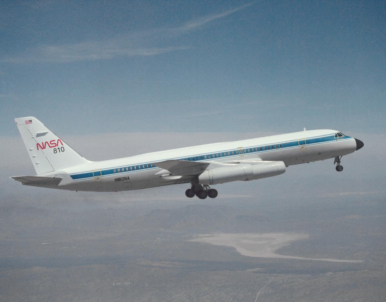
A NASA CV-990, modified as a Landing Systems Research Aircraft (LSRA), is serviced on the ramp at NASA's Dryden Flight Research Center, Edwards, California, before a test of the space shuttle landing gear system. The space shuttle landing gear test unit, operated by a high-pressure hydraulic system, allowed engineers to assess and document the performance of space shuttle main and nose landing gear systems, tires and wheel assemblies, plus braking and nose wheel steering performance. The series of 155 test missions for the space shuttle program provided extensive data about the life and endurance of the shuttle tire systems and helped raise the shuttle crosswind landing limits at Kennedy.
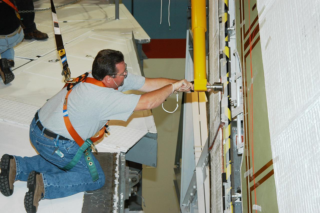
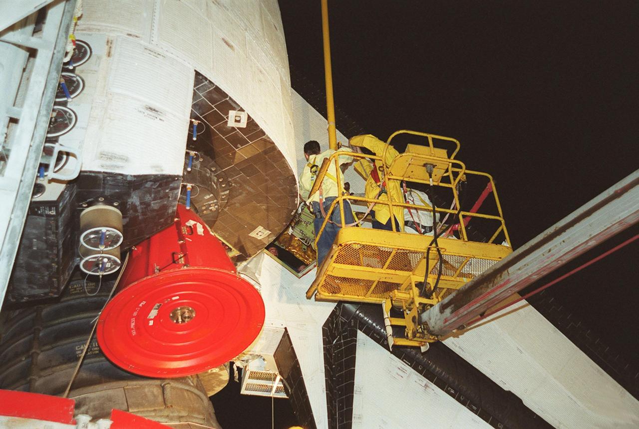
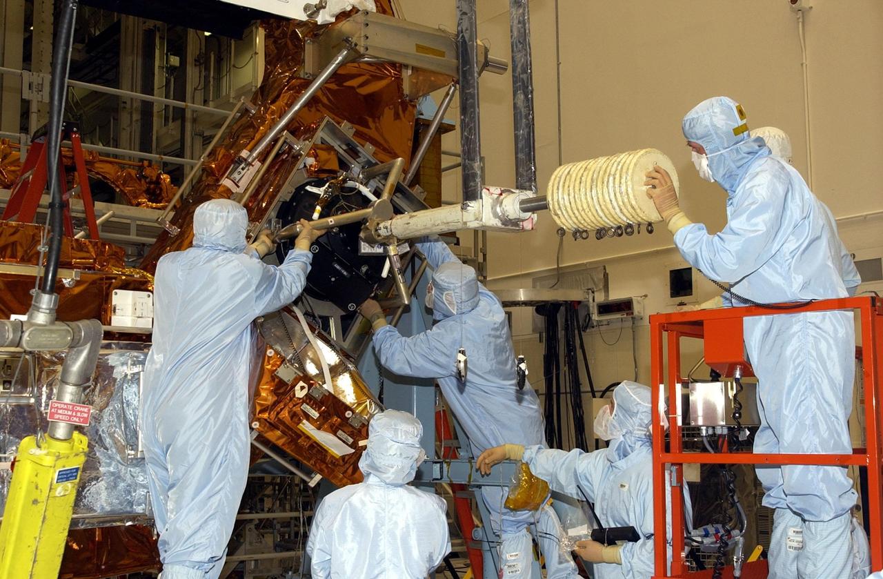
KENNEDY SPACE CENTER, FLA. -- In the Orbiter Processing Facility, a worker tightens a fitting on the device being used to remove the Rudder Speed Brake panel on the vertical tail of the orbiter Atlantis. The Rudder Speed Brake is being removed for inspection and maintenance prior to Return to Flight. The vertical tail consists of a structural fin surface made of aluminum, the Rudder Speed Brake surface, a tip and a lower trailing edge. The rudder splits into two halves to serve as a speed brake. The vertical tail and Rudder Speed Brake are covered with a reusable thermal protection system. The Rudder Speed Brake is used to guide and slow the Shuttle as it comes in for a landing.
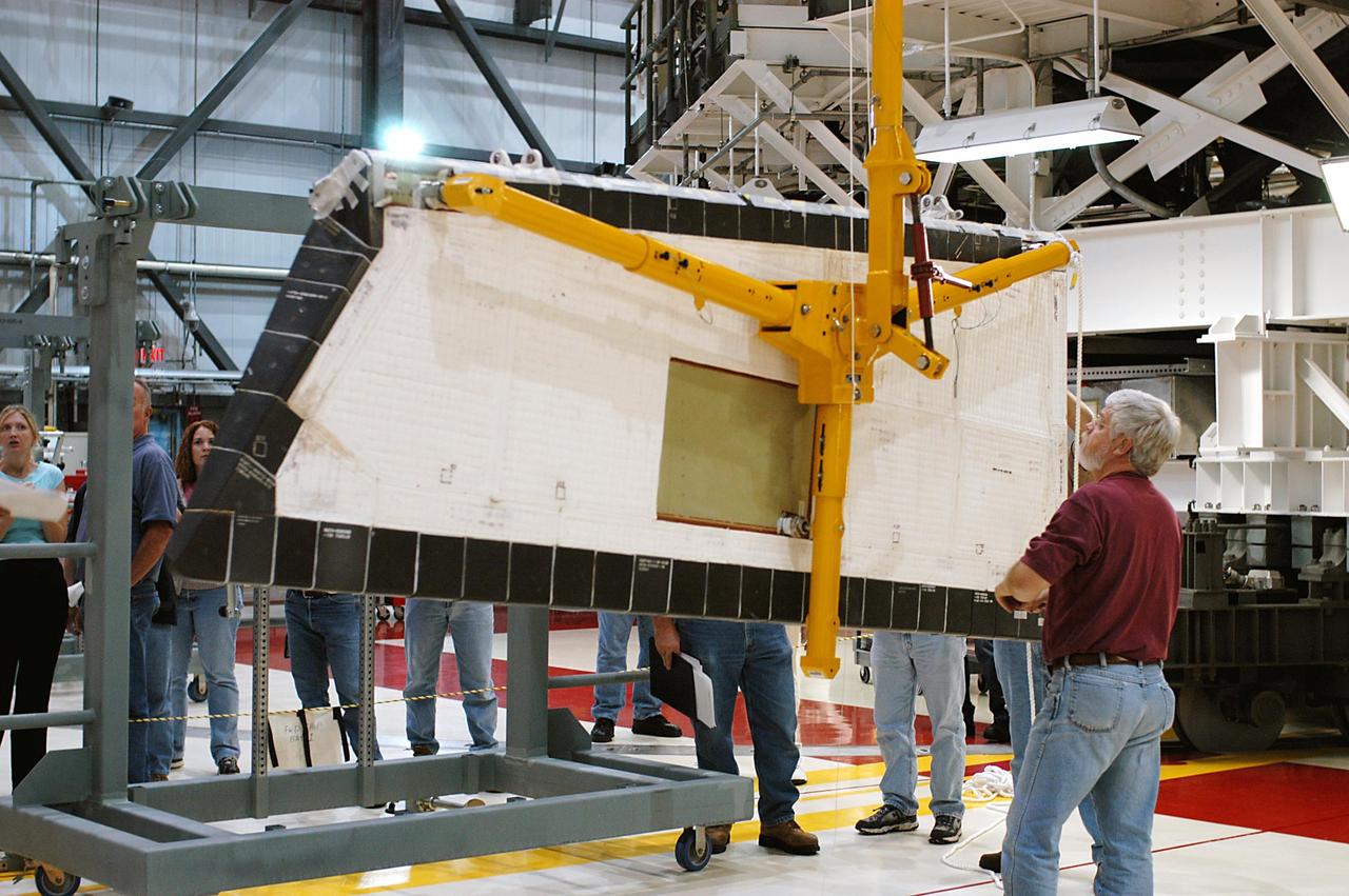
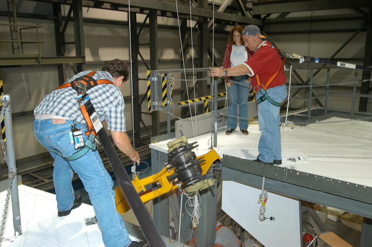
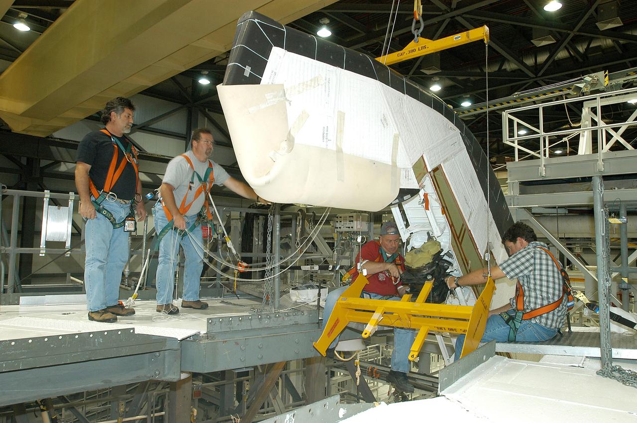
KENNEDY SPACE CENTER, FLA. -- In the Orbiter Processing Facility, workers lower Atlantis’ Rudder Speed Brake panel toward the floor after removing the panel from the vertical tail. The Rudder Speed Brake is being removed for inspection and maintenance prior to Return to Flight. The vertical tail consists of a structural fin surface made of aluminum, the Rudder Speed Brake surface, a tip and a lower trailing edge. The rudder splits into two halves to serve as a speed brake. The vertical tail and Rudder Speed Brake are covered with a reusable thermal protection system. The Rudder Speed Brake is used to guide and slow the Shuttle as it comes in for a landing.

KENNEDY SPACE CENTER, FLA. -- In the Orbiter Processing Facility, workers attach Atlantis’ Rudder Speed Brake panel to a stand after removing the panel from the vertical tail. The Rudder Speed Brake is being removed for inspection and maintenance prior to Return to Flight. The vertical tail consists of a structural fin surface made of aluminum, the Rudder Speed Brake surface, a tip and a lower trailing edge. The rudder splits into two halves to serve as a speed brake. The vertical tail and Rudder Speed Brake are covered with a reusable thermal protection system. The Rudder Speed Brake is used to guide and slow the Shuttle as it comes in for a landing.
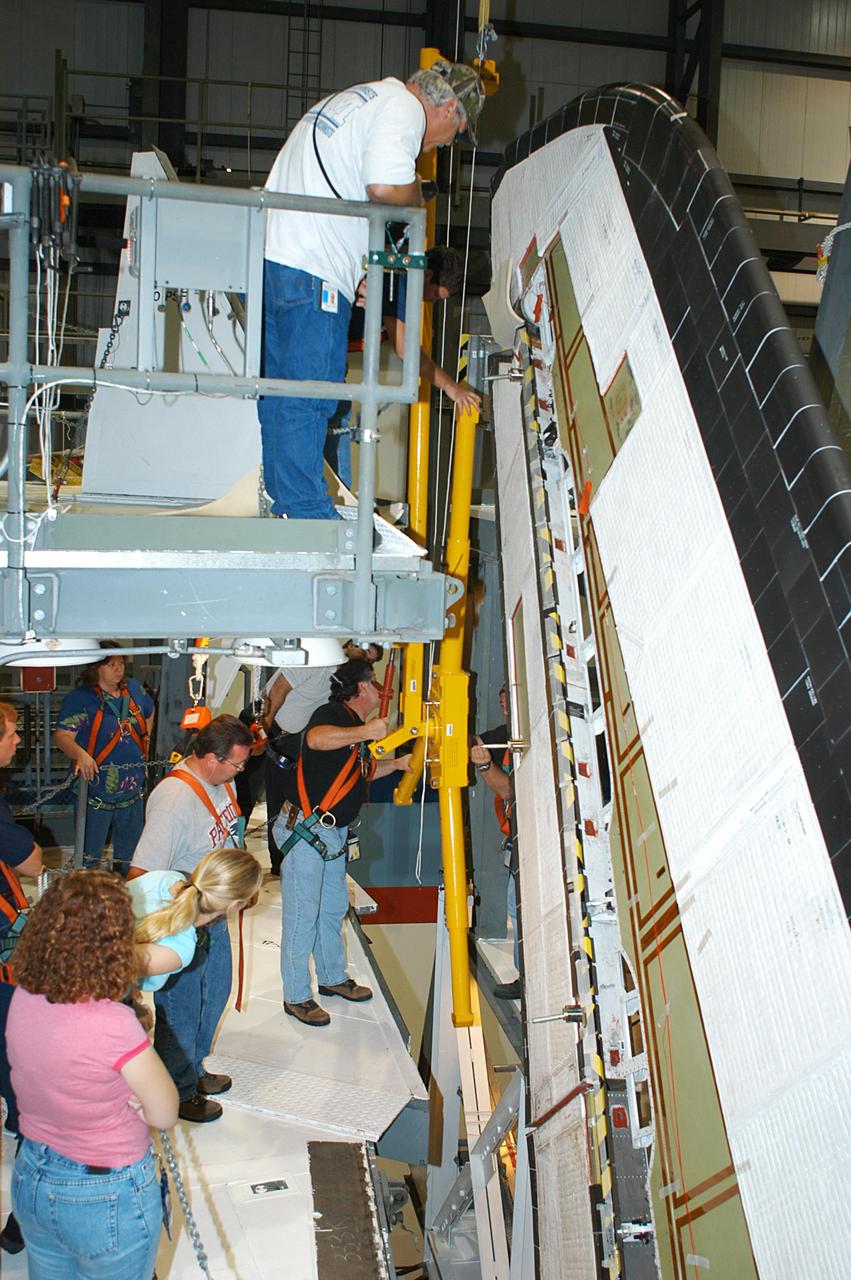
KENNEDY SPACE CENTER, FLA. -- In the Orbiter Processing Facility, a worker (below the upper framework) begins connecting a device to remove the Rudder Speed Brake panel on the vertical tail of orbiter Atlantis. The Rudder Speed Brake is being removed for inspection and maintenance prior to Return to Flight. The vertical tail consists of a structural fin surface made of aluminum, the Rudder Speed Brake surface, a tip and a lower trailing edge. The rudder splits into two halves to serve as a speed brake. The vertical tail and Rudder Speed Brake are covered with a reusable thermal protection system. The Rudder Speed Brake is used to guide and slow the Shuttle as it comes in for a landing.
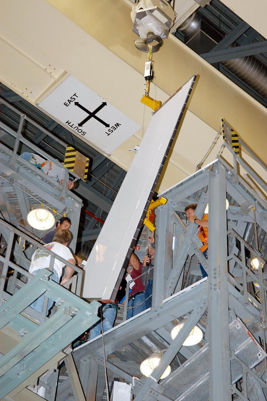
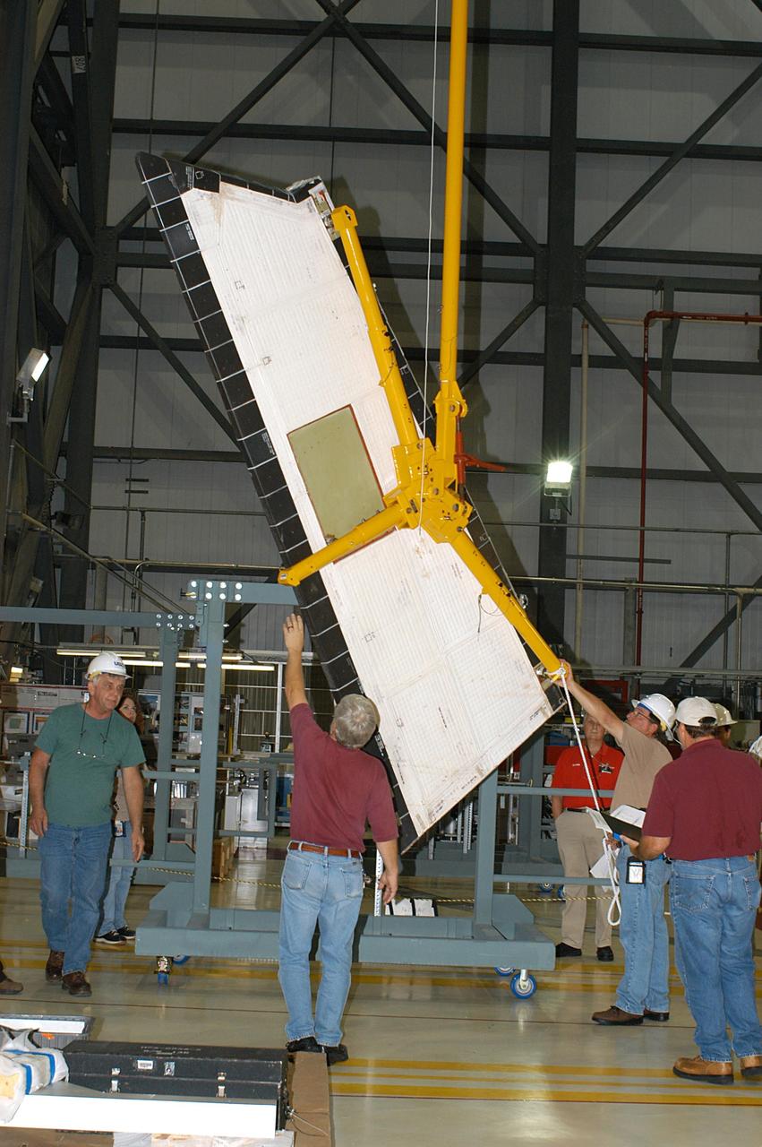
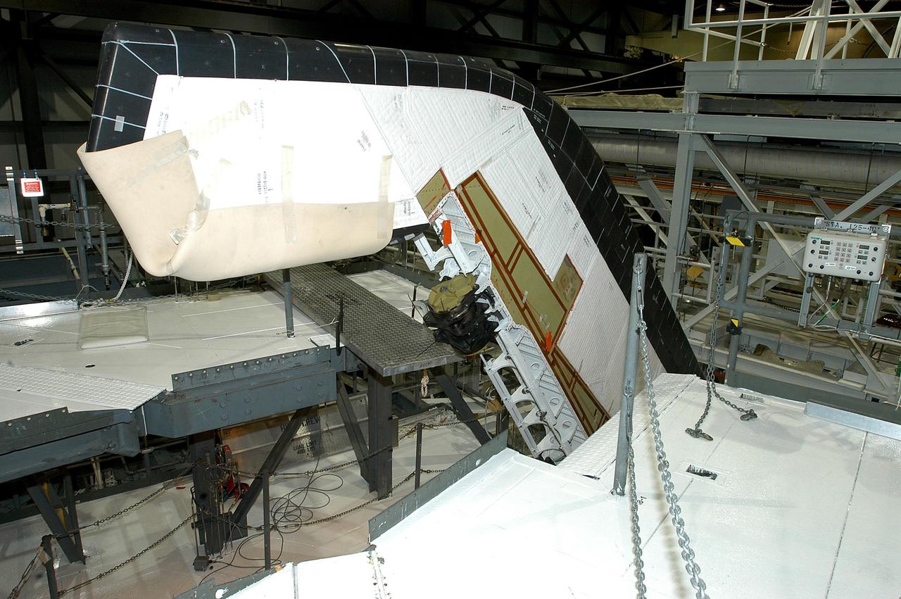
KENNEDY SPACE CENTER, FLA. -- In the Orbiter Processing Facility, the Rudder Speed Brake panel from orbiter Atlantis is lifted clear after being removed. The Rudder Speed Brake is being removed for inspection and maintenance prior to Return to Flight. The vertical tail consists of a structural fin surface made of aluminum, the Rudder Speed Brake surface, a tip and a lower trailing edge. The rudder splits into two halves to serve as a speed brake. The vertical tail and Rudder Speed Brake are covered with a reusable thermal protection system. The Rudder Speed Brake is used to guide and slow the Shuttle as it comes in for a landing.
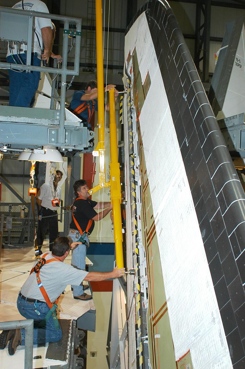
KENNEDY SPACE CENTER, FLA. -- In the Orbiter Processing Facility, workers connect a device onto the vertical tail of the orbiter Atlantis to remove the Rudder Speed Brake panel. The Rudder Speed Brake is being removed for inspection and maintenance prior to Return to Flight. The vertical tail consists of a structural fin surface made of aluminum, the Rudder Speed Brake surface, a tip and a lower trailing edge. The rudder splits into two halves to serve as a speed brake. The vertical tail and Rudder Speed Brake are covered with a reusable thermal protection system. The Rudder Speed Brake is used to guide and slow the Shuttle as it comes in for a landing.
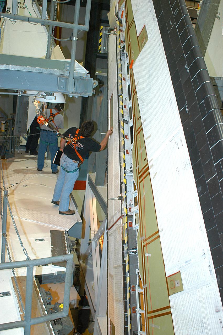
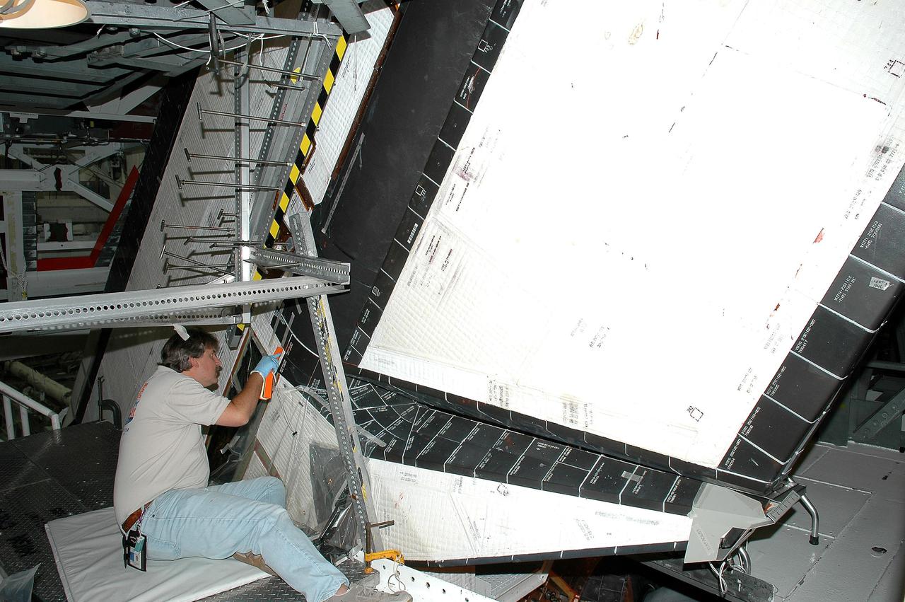
KENNEDY SPACE CENTER, FLA. -- In the Orbiter Processing Facility, a technician looks at the Rudder Speed Brake panel on the vertical tail of orbiter Atlantis. The Rudder Speed Brake is being removed for inspection and maintenance prior to Return to Flight. The vertical tail consists of a structural fin surface made of aluminum, the Rudder Speed Brake surface, a tip and a lower trailing edge. The rudder splits into two halves to serve as a speed brake. The vertical tail and Rudder Speed Brake are covered with a reusable thermal protection system. The Rudder Speed Brake is used to guide and slow the Shuttle as it comes in for a landing.
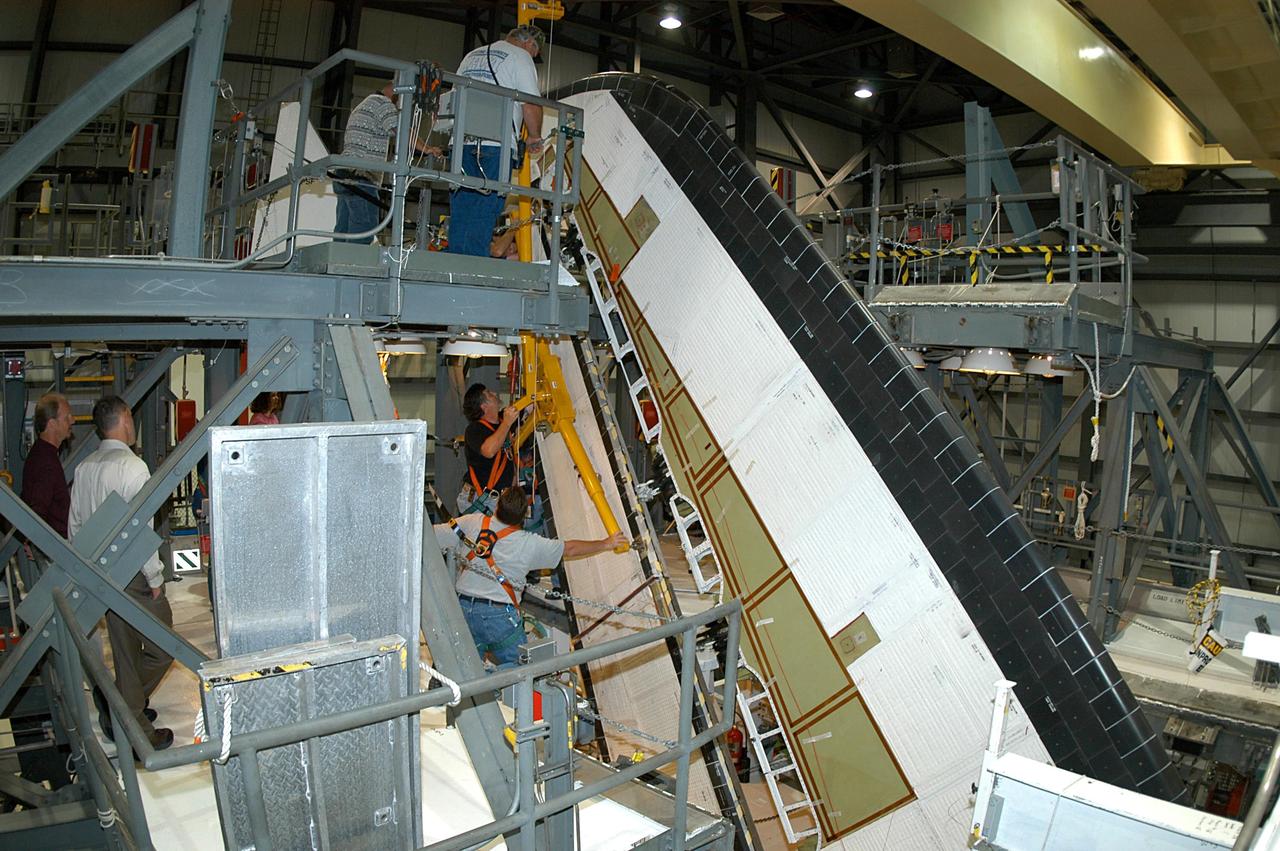
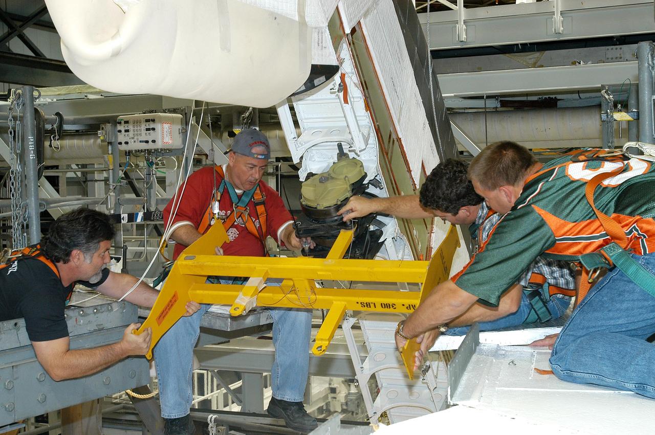
KENNEDY SPACE CENTER, FLA. -- In the Orbiter Processing Facility, workers begin removing the Rudder Speed Brake panel on the vertical tail of the orbiter Atlantis. The Rudder Speed Brake is being removed for inspection and maintenance prior to Return to Flight. The vertical tail consists of a structural fin surface made of aluminum, the Rudder Speed Brake surface, a tip and a lower trailing edge. The rudder splits into two halves to serve as a speed brake. The vertical tail and Rudder Speed Brake are covered with a reusable thermal protection system. The Rudder Speed Brake is used to guide and slow the Shuttle as it comes in for a landing.
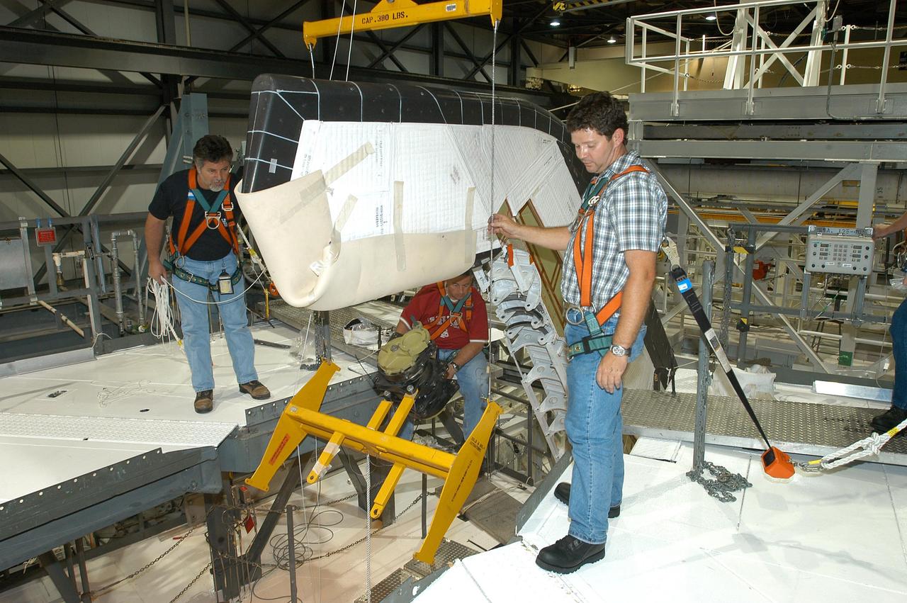
KENNEDY SPACE CENTER, FLA. -- In the Orbiter Processing Facility, workers lower Atlantis’ Rudder Speed Brake panel onto a stand after removing the panel from the vertical tail. The Rudder Speed Brake is being removed for inspection and maintenance prior to Return to Flight. The vertical tail consists of a structural fin surface made of aluminum, the Rudder Speed Brake surface, a tip and a lower trailing edge. The rudder splits into two halves to serve as a speed brake. The vertical tail and Rudder Speed Brake are covered with a reusable thermal protection system. The Rudder Speed Brake is used to guide and slow the Shuttle as it comes in for a landing.
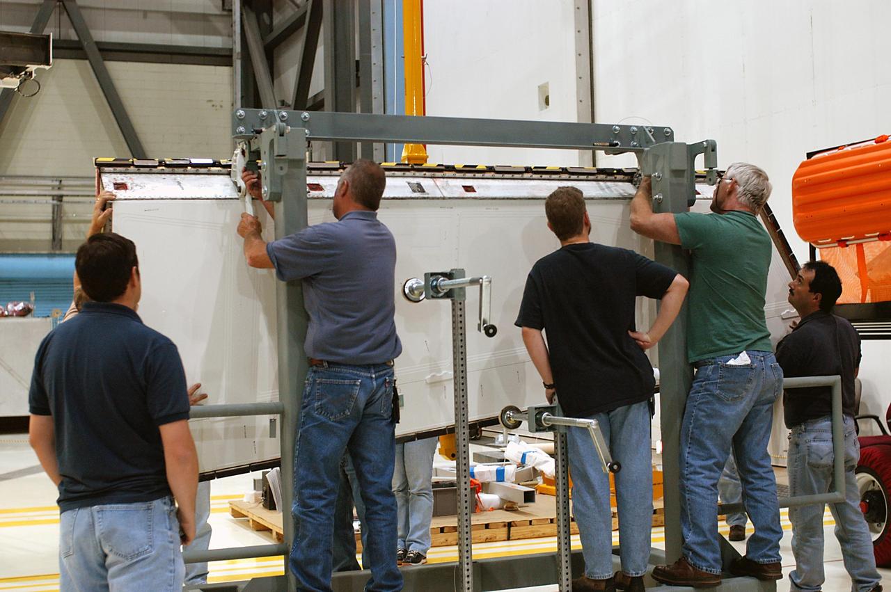
KENNEDY SPACE CENTER, FLA. -- In the Orbiter Processing Facility, workers attach Atlantis’ Rudder Speed Brake panel to a stand after removing the panel from the vertical tail. The Rudder Speed Brake is being removed for inspection and maintenance prior to Return to Flight. The vertical tail consists of a structural fin surface made of aluminum, the Rudder Speed Brake surface, a tip and a lower trailing edge. The rudder splits into two halves to serve as a speed brake. The vertical tail and Rudder Speed Brake are covered with a reusable thermal protection system. The Rudder Speed Brake is used to guide and slow the Shuttle as it comes in for a landing.
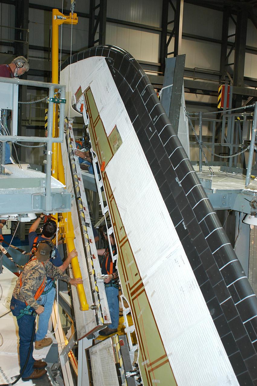
KENNEDY SPACE CENTER, FLA. -- In the Orbiter Processing Facility, workers remove the Rudder Speed Brake panel on the vertical tail of the orbiter Atlantis. The Rudder Speed Brake is being removed for inspection and maintenance prior to Return to Flight. The vertical tail consists of a structural fin surface made of aluminum, the Rudder Speed Brake surface, a tip and a lower trailing edge. The rudder splits into two halves to serve as a speed brake. The vertical tail and Rudder Speed Brake are covered with a reusable thermal protection system. The Rudder Speed Brake is used to guide and slow the Shuttle as it comes in for a landing.
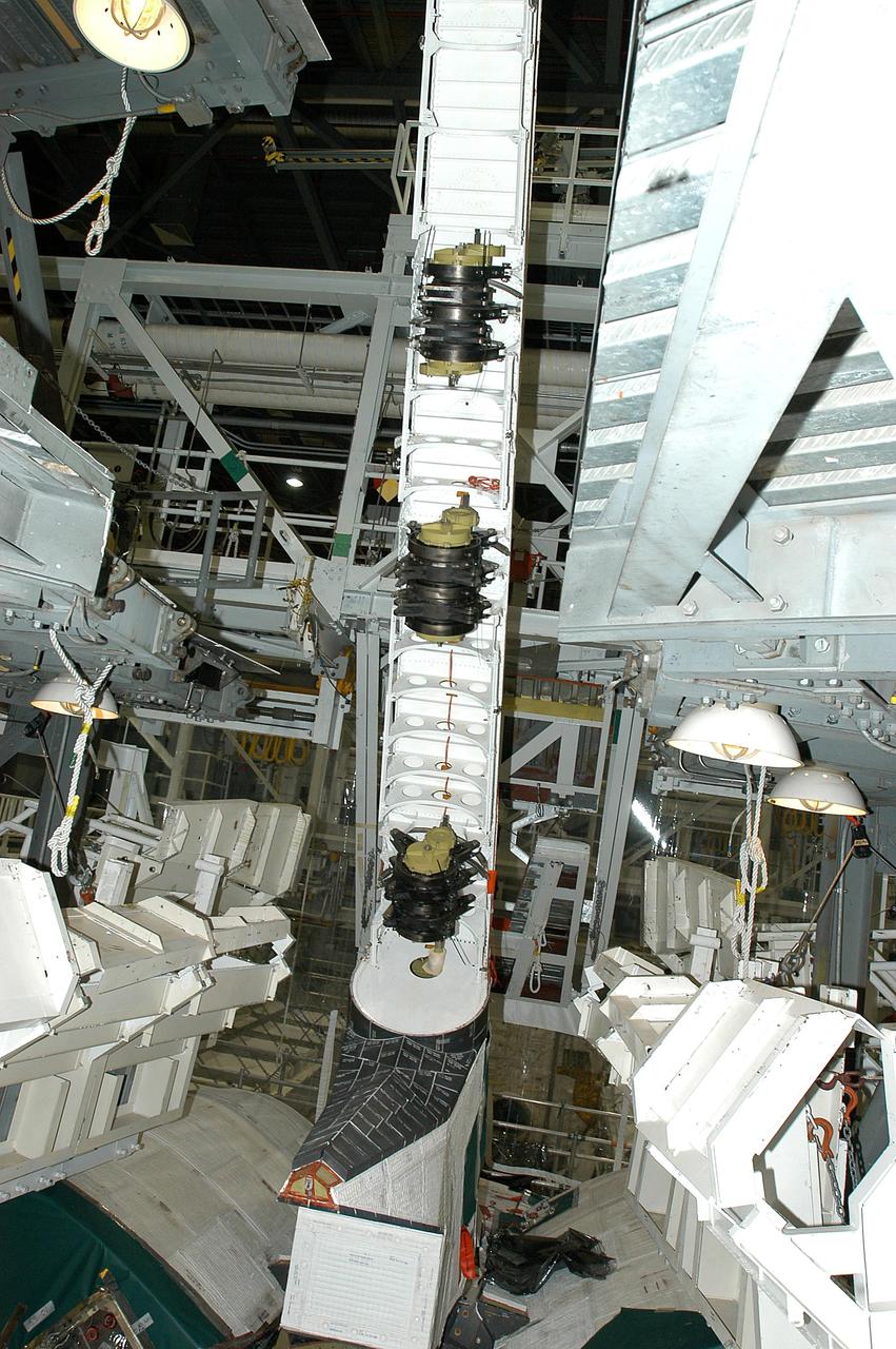
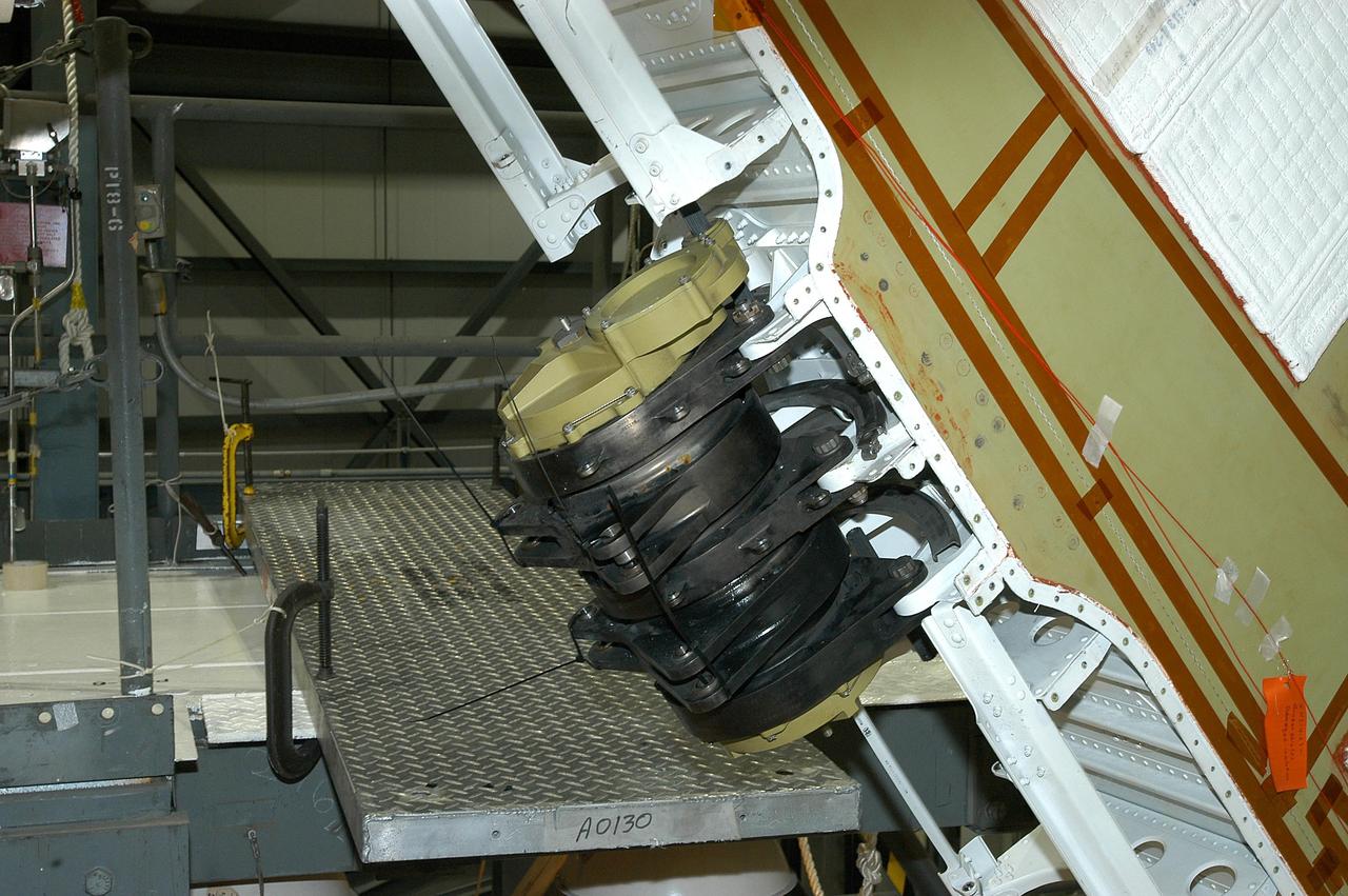
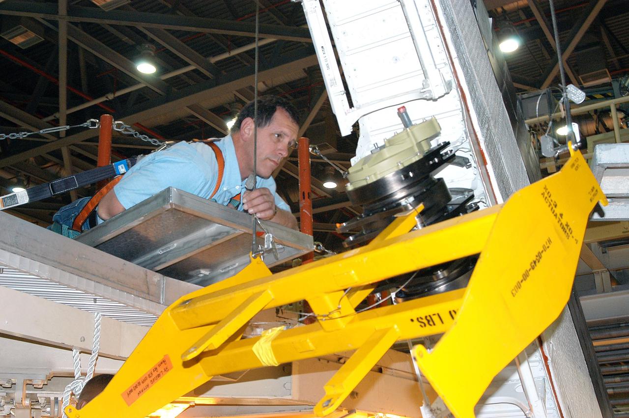
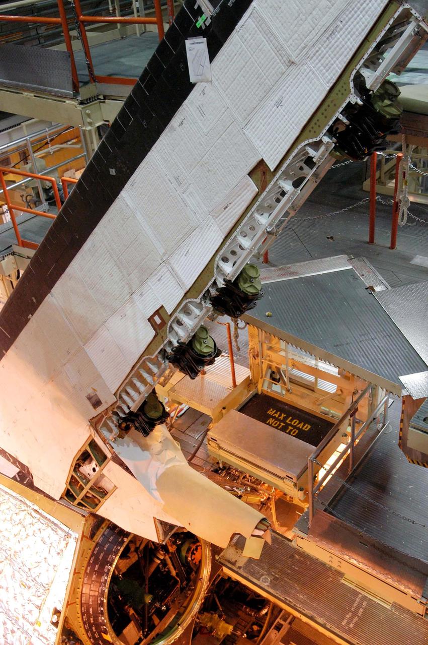
KENNEDY SPACE CENTER, FLA. -- A Rudder Speed Brake Actuator is being removed from the orbiter Atlantis for shipment to the vendor for inspection. An actuator is a motor that moves the tail rudder back and forth to help steer it during landing and brake its speed. The vertical tail consists of a structural fin surface made of aluminum, the Rudder Speed Brake surface, a tip and a lower trailing edge. The rudder splits into two halves to serve as a speed brake. The vertical tail and Rudder Speed Brake are covered with a reusable thermal protection system. Atlantis is undergoing maintenance and inspection in the Orbiter Processing Facility for a future mission.
KENNEDY SPACE CENTER, FLA. -- Workers attach a crane to one of the Rudder Speed Brake Actuators that are being removed from the orbiter Atlantis for shipment to the vendor for inspection. An actuator is a motor that moves the tail rudder back and forth to help steer it during landing and brake its speed. The vertical tail consists of a structural fin surface made of aluminum, the Rudder Speed Brake surface, a tip and a lower trailing edge. The rudder splits into two halves to serve as a speed brake. The vertical tail and Rudder Speed Brake are covered with a reusable thermal protection system. Atlantis is undergoing maintenance and inspection in the Orbiter Processing Facility for a future mission.
KENNEDY SPACE CENTER, FLA. -- Workers ensure the safe removal of a Rudder Speed Brake Actuator from the orbiter Atlantis. This and three other actuators are being shipped to the vendor for inspection. An actuator is a motor that moves the tail rudder back and forth to help steer it during landing and brake its speed. The vertical tail consists of a structural fin surface made of aluminum, the Rudder Speed Brake surface, a tip and a lower trailing edge. The rudder splits into two halves to serve as a speed brake. The vertical tail and Rudder Speed Brake are covered with a reusable thermal protection system. Atlantis is undergoing maintenance and inspection in the Orbiter Processing Facility for a future mission.
KENNEDY SPACE CENTER, FLA. -- A Rudder Speed Brake Actuator is being removed from the orbiter Atlantis for shipment to the vendor for inspection. An actuator is a motor that moves the tail rudder back and forth to help steer it during landing and brake its speed. The vertical tail consists of a structural fin surface made of aluminum, the Rudder Speed Brake surface, a tip and a lower trailing edge. The rudder splits into two halves to serve as a speed brake. The vertical tail and Rudder Speed Brake are covered with a reusable thermal protection system. Atlantis is undergoing maintenance and inspection in the Orbiter Processing Facility for a future mission.
KENNEDY SPACE CENTER, FLA. -- Workers ensure the safe removal of a Rudder Speed Brake Actuator from the orbiter Atlantis. This and three other actuators are being shipped to the vendor for inspection. An actuator is a motor that moves the tail rudder back and forth to help steer it during landing and brake its speed. The vertical tail consists of a structural fin surface made of aluminum, the Rudder Speed Brake surface, a tip and a lower trailing edge. The rudder splits into two halves to serve as a speed brake. The vertical tail and Rudder Speed Brake are covered with a reusable thermal protection system. Atlantis is undergoing maintenance and inspection in the Orbiter Processing Facility for a future mission.
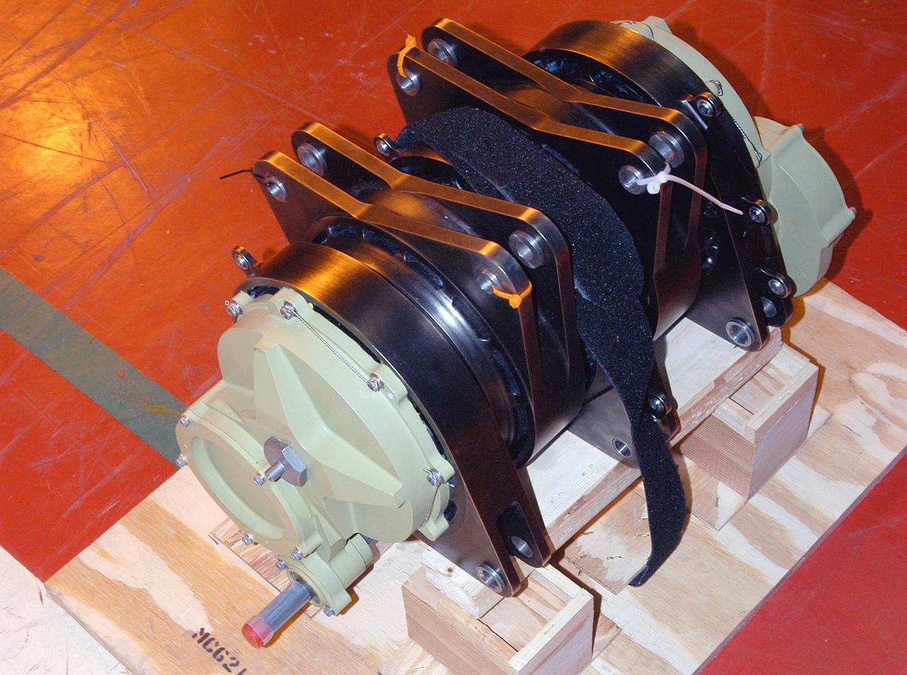
KENNEDY SPACE CENTER, FLA. -- A Rudder Speed Brake Actuator from the orbiter Atlantis is set on a stand on the floor of the Orbiter Processing Facility. This and three other actuators are being shipped to the vendor for inspection. An actuator is a motor that moves the tail rudder back and forth to help steer it during landing and brake its speed. The vertical tail consists of a structural fin surface made of aluminum, the Rudder Speed Brake surface, a tip and a lower trailing edge. The rudder splits into two halves to serve as a speed brake. The vertical tail and Rudder Speed Brake are covered with a reusable thermal protection system. Atlantis is undergoing maintenance and inspection for a future mission.
KENNEDY SPACE CENTER, FLA. -- Workers attach a crane to one of the Rudder Speed Brake Actuators that are being removed from the orbiter Atlantis for shipment to the vendor for inspection. An actuator is a motor that moves the tail rudder back and forth to help steer it during landing and brake its speed. The vertical tail consists of a structural fin surface made of aluminum, the Rudder Speed Brake surface, a tip and a lower trailing edge. The rudder splits into two halves to serve as a speed brake. The vertical tail and Rudder Speed Brake are covered with a reusable thermal protection system. Atlantis is undergoing maintenance and inspection in the Orbiter Processing Facility for a future mission.
KENNEDY SPACE CENTER, FLA. -- This is a closeup of one of the Rudder Speed Brake Actuators that are being removed from the orbiter Atlantis for shipment to the vendor for inspection. An actuator is a motor that moves the tail rudder back and forth to help steer it during landing and brake its speed. The vertical tail consists of a structural fin surface made of aluminum, the Rudder Speed Brake surface, a tip and a lower trailing edge. The rudder splits into two halves to serve as a speed brake. The vertical tail and Rudder Speed Brake are covered with a reusable thermal protection system. Atlantis is undergoing maintenance and inspection in the Orbiter Processing Facility for a future mission.

This diagram illustrates research from NASA Galaxy Evolution Explorer showing that black holes once they reach a critical size can put the brakes on new star formation in elliptical galaxies.
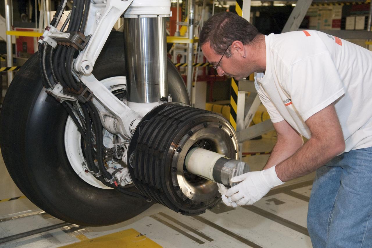
STS-133 ENDEAVOUR TIRES AND BRAKES REMOVAL
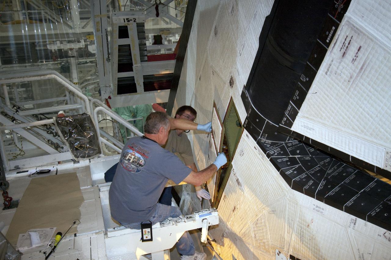
STS-132 ATLANTIS RUDDER SPEED BRAKE CLOSEOUT
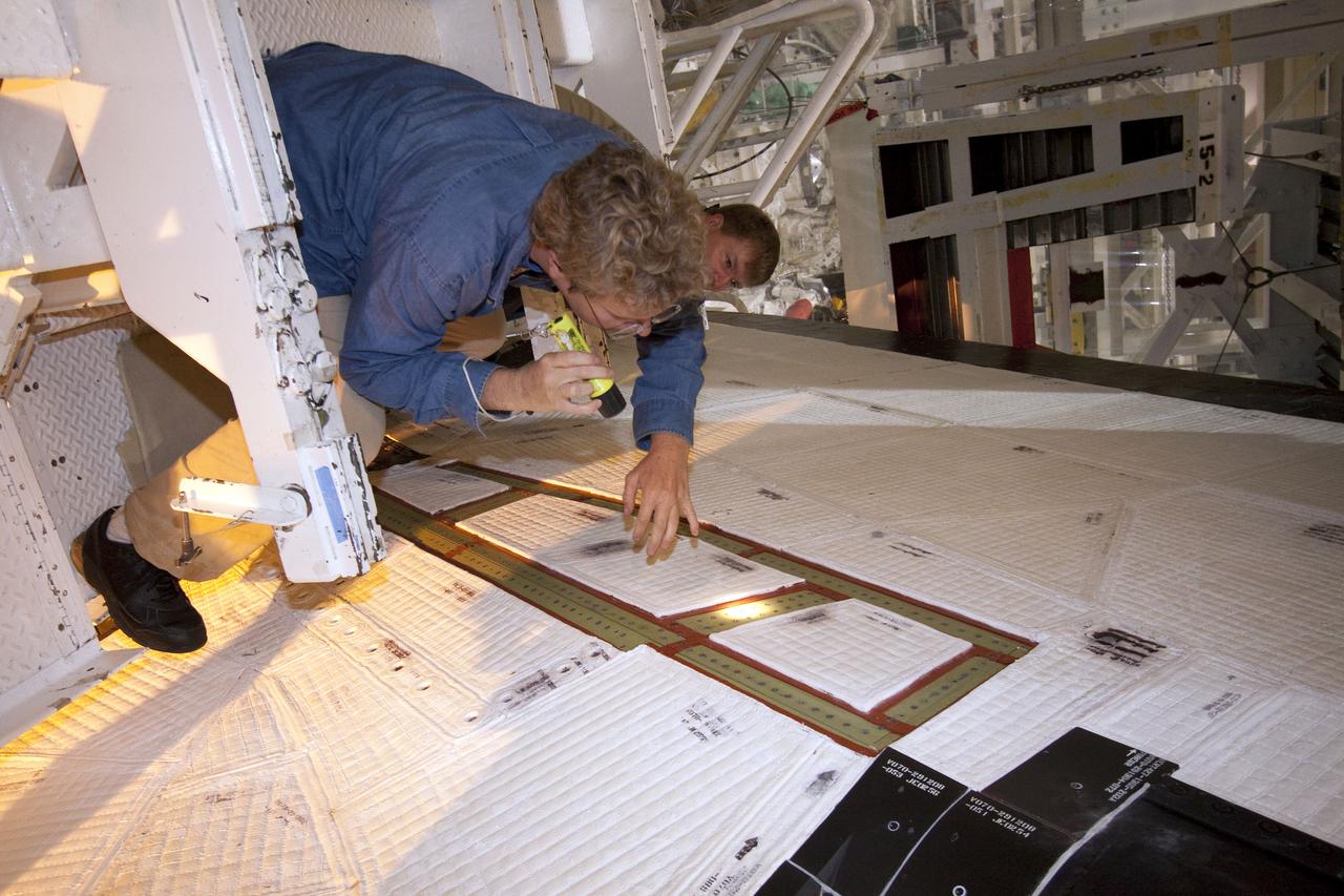
STS-132 ATLANTIS RUDDER SPEED BRAKE CLOSEOUT
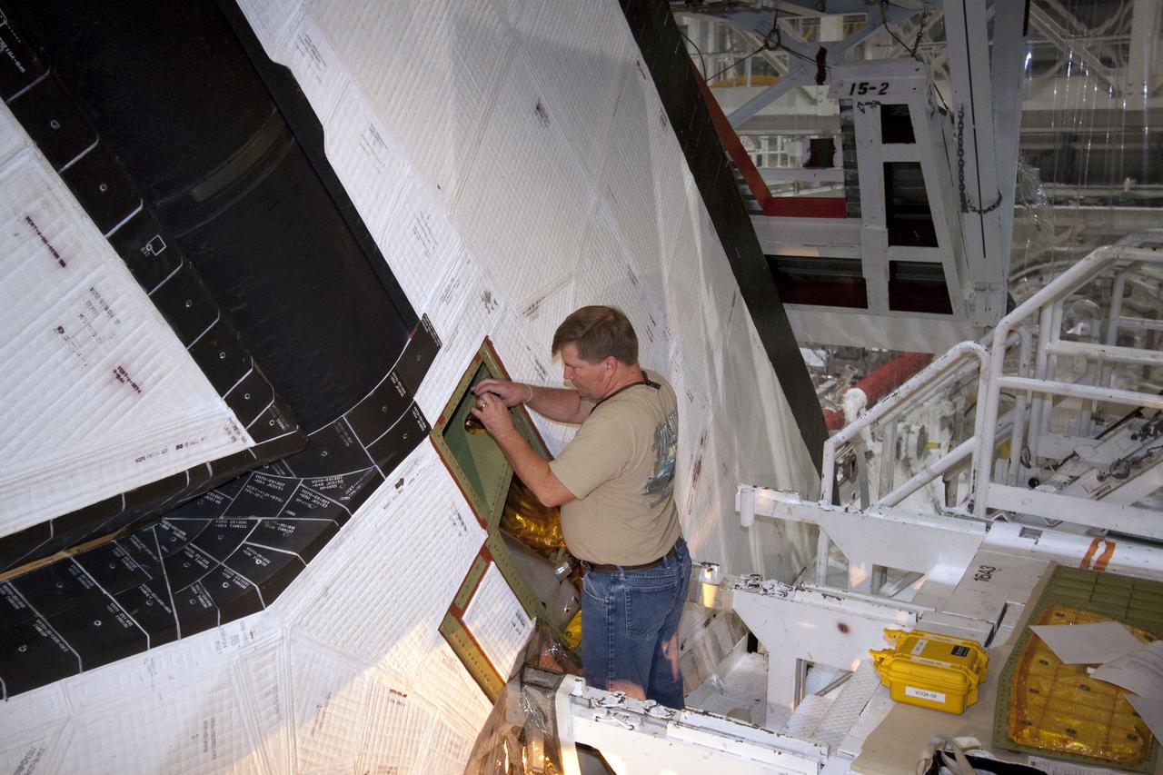
STS-132 ATLANTIS RUDDER SPEED BRAKE CLOSEOUT
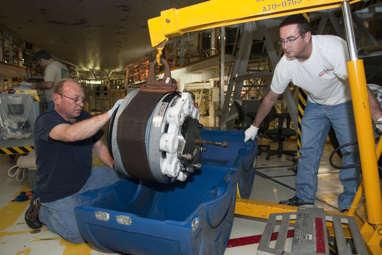
STS-133 ENDEAVOUR TIRES AND BRAKES REMOVAL
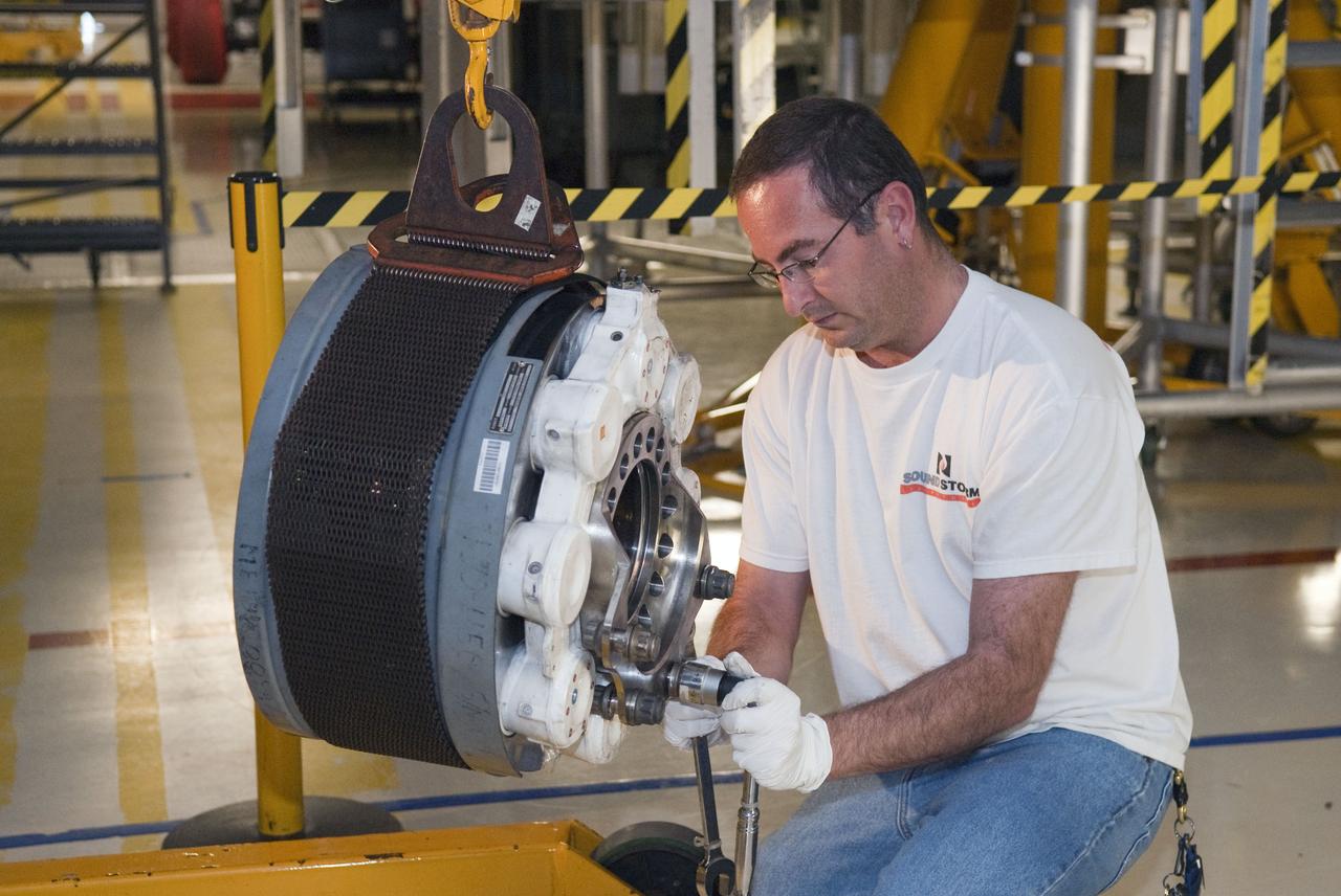
STS-133 ENDEAVOUR TIRES AND BRAKES REMOVAL
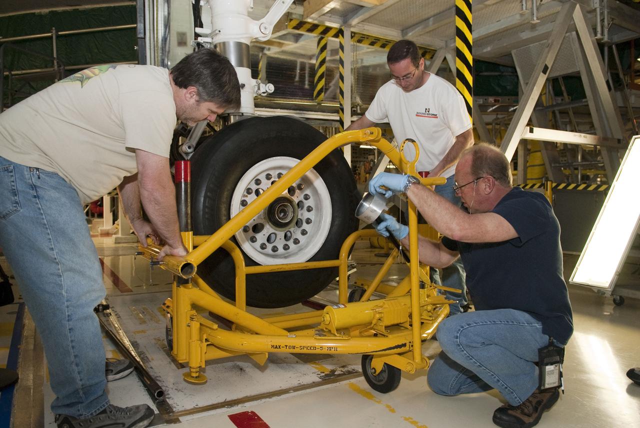
STS-133 ENDEAVOUR TIRES AND BRAKES REMOVAL
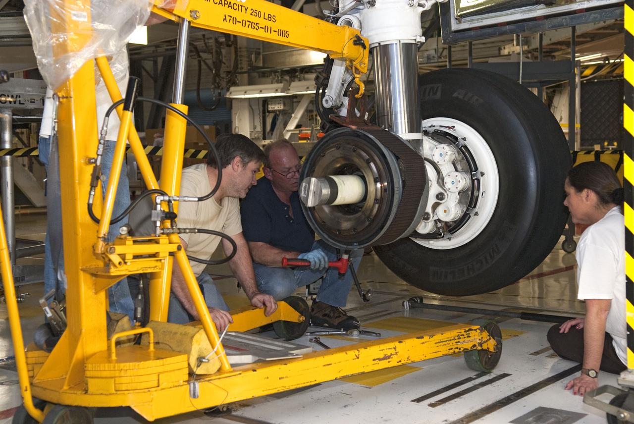
STS-133 ENDEAVOUR TIRES AND BRAKES REMOVAL
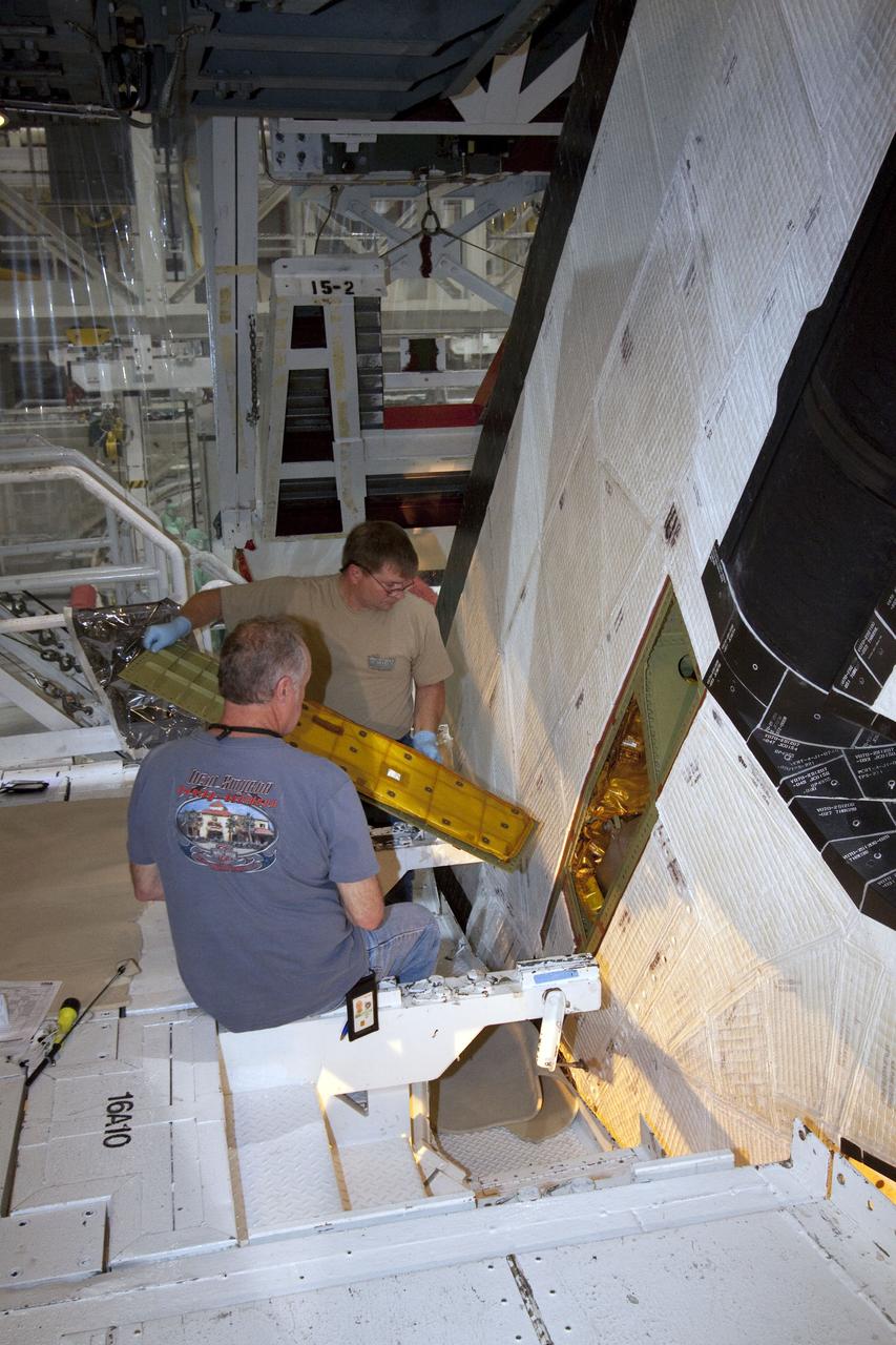
STS-132 ATLANTIS RUDDER SPEED BRAKE CLOSEOUT
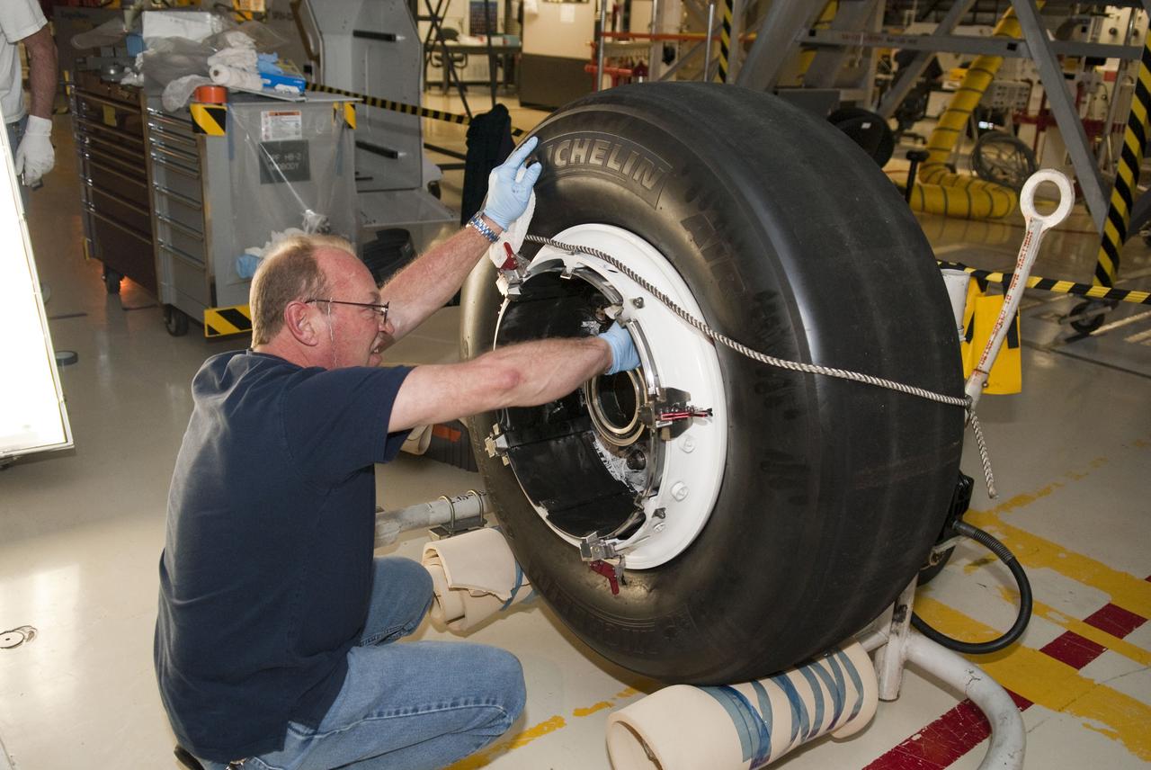
STS-133 ENDEAVOUR TIRES AND BRAKES REMOVAL
KENNEDY SPACE CENTER, FLA. - Workers at Cape Canaveral Air Force Station place one of four rudder speed brake actuators onto a pallet for X-ray. The actuators, to be installed on the orbiter Discovery, are being X-rayed at the Radiographic High-Energy X-ray Facility to determine if the gears were installed correctly. Discovery has been assigned to the first Return to Flight mission, STS-114, a logistics flight to the International Space Station.
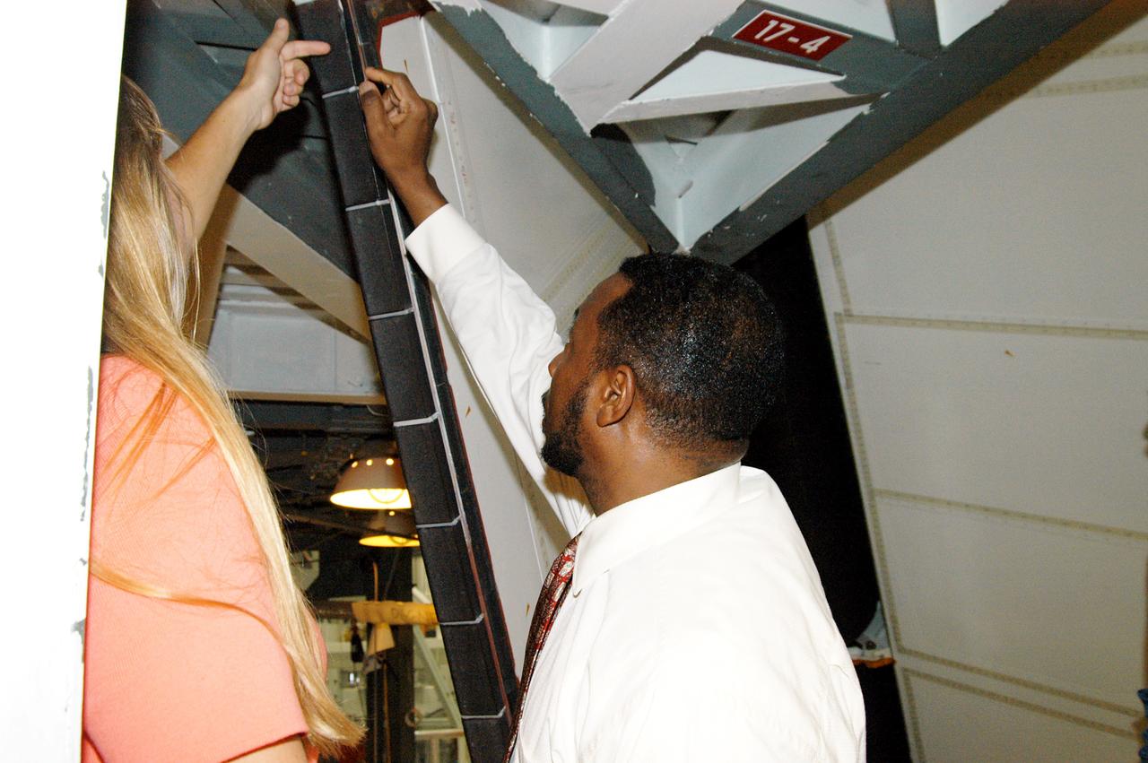
KENNEDY SPACE CENTER, FLA. - On a tour of the Orbiter Processing Facility, Kathy Laufenberg (left) directs the attention of Deputy Director Woodrow Whitlow Jr. to an area on a rudder speed brake panel on Endeavour. The Center Director, Jim Kennedy, and Whitlow are on a tour of the Orbiter Processing Facility. Endeavour is in its Orbiter Major Modification period, which began in December 2003.
KENNEDY SPACE CENTER, FLA. - A rudder speed brake actuator sits on an air-bearing pallet to undergo X-raying. Four actuators to be installed on the orbiter Discovery are being X-rayed at the Radiographic High-Energy X-ray Facility to determine if the gears were installed correctly. Discovery has been assigned to the first Return to Flight mission, STS-114, a logistics flight to the International Space Station.
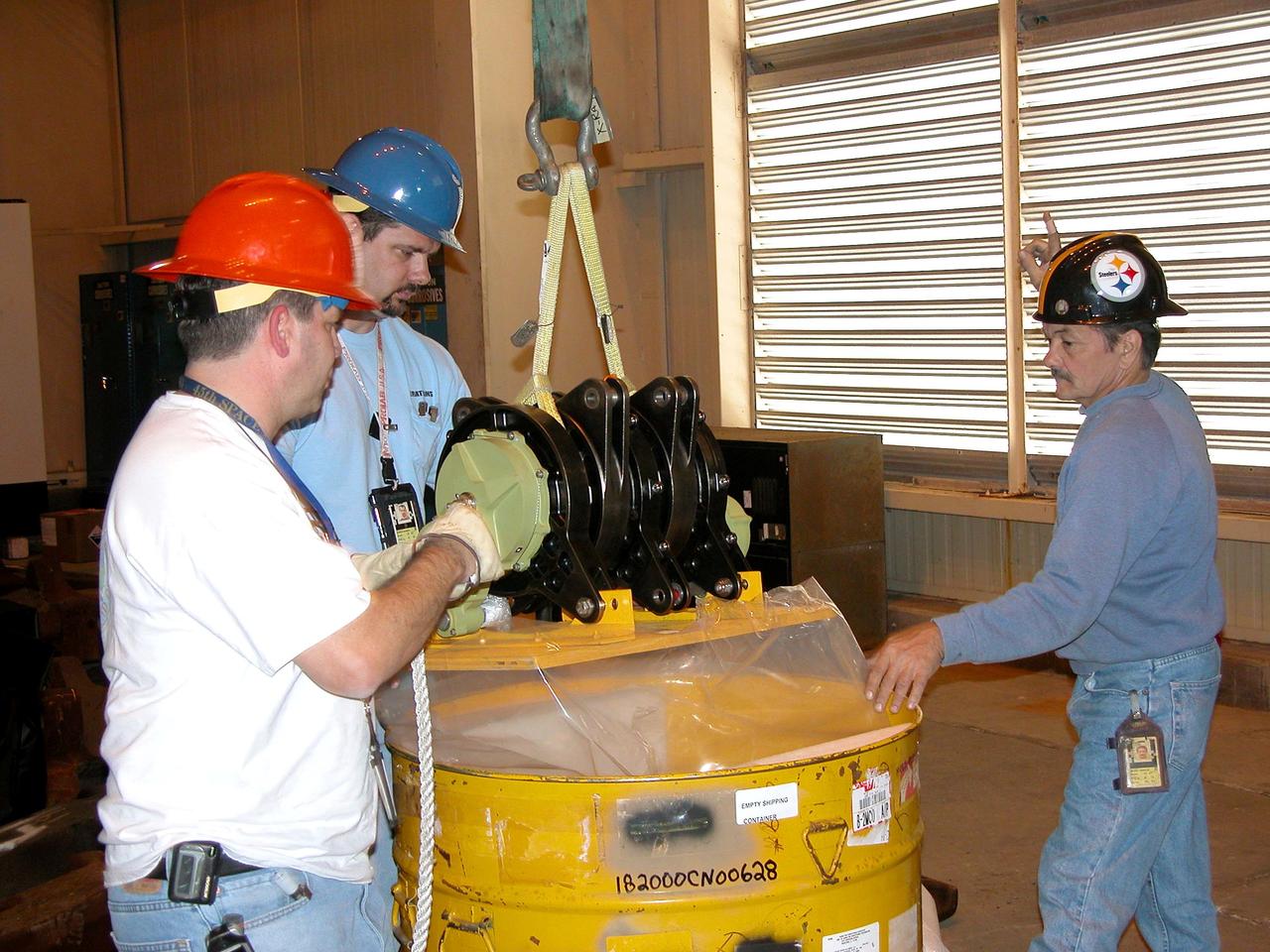
KENNEDY SPACE CENTER, FLA. - One of four rudder speed brake actuators arrives at Cape Canaveral Air Force Station. The actuators, to be installed on the orbiter Discovery, are being X-rayed at the Radiographic High-Energy X-ray Facility to determine if the gears were installed correctly. Discovery has been assigned to the first Return to Flight mission, STS-114, a logistics flight to the International Space Station.
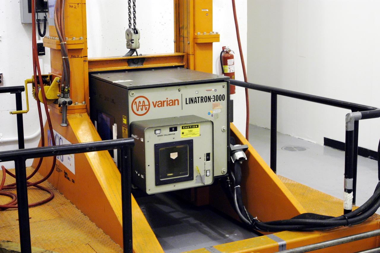
KENNEDY SPACE CENTER, FLA. - An X-ray machine is in place to take images of four rudder speed brake actuators to be installed on the orbiter Discovery. The actuators are being X-rayed at the Cape Canaveral Air Force Station’s Radiographic High-Energy X-ray Facility to determine if the gears were installed correctly. Discovery has been assigned to the first Return to Flight mission, STS-114, a logistics flight to the International Space Station.
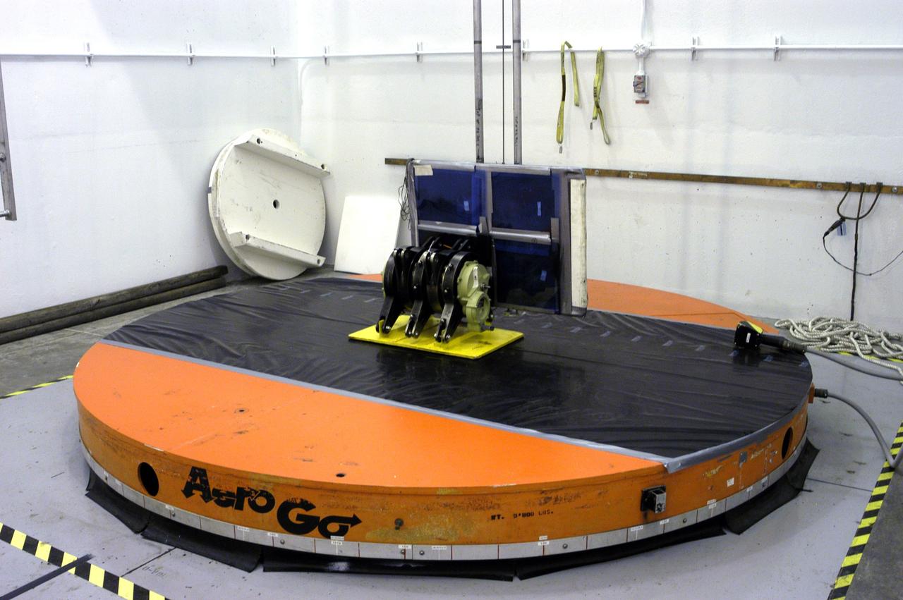
KENNEDY SPACE CENTER, FLA. - A rudder speed brake actuator sits on an air-bearing pallet to undergo X-raying. Four actuators to be installed on the orbiter Discovery are being X-rayed at the Radiographic High-Energy X-ray Facility to determine if the gears were installed correctly. Discovery has been assigned to the first Return to Flight mission, STS-114, a logistics flight to the International Space Station.
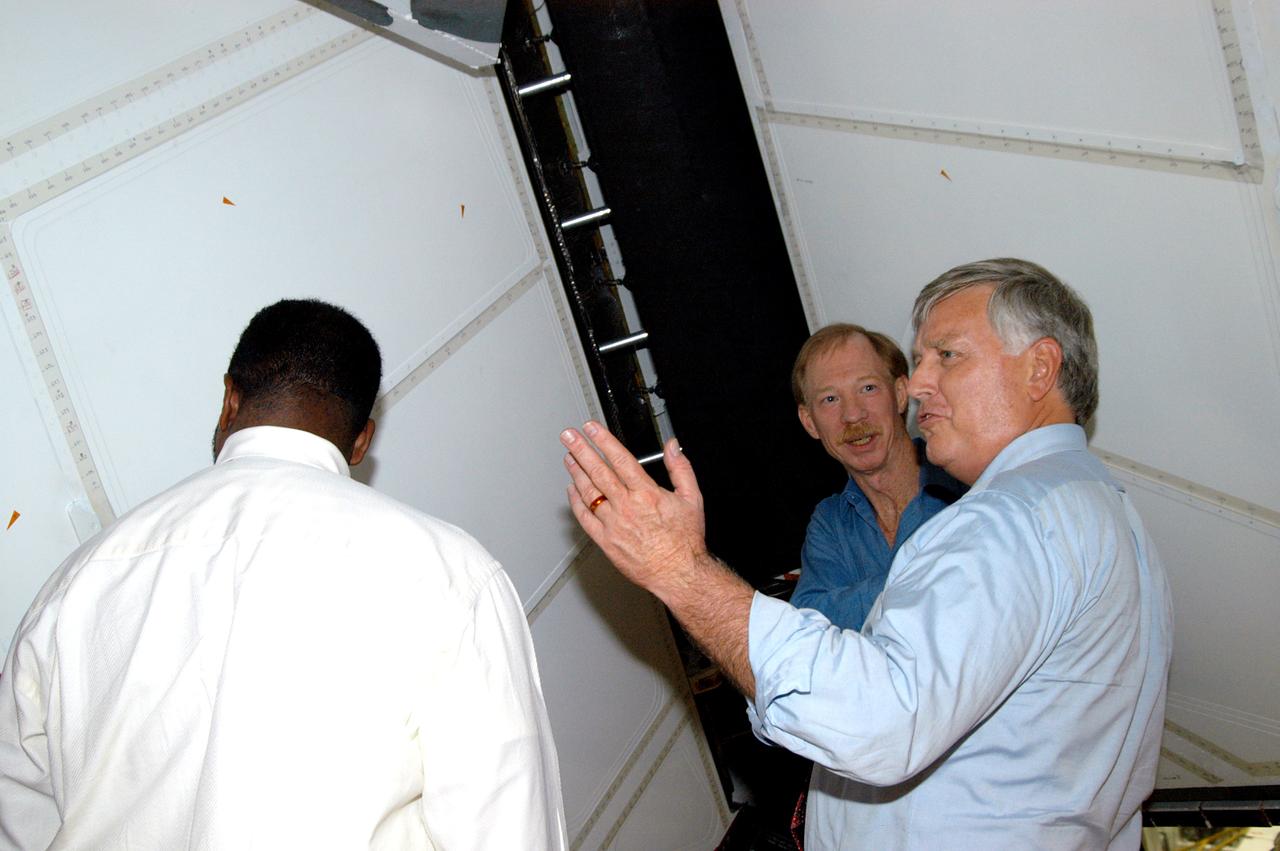
KENNEDY SPACE CENTER, FLA. - On a tour of the Orbiter Processing Facility, Center Director Jim Kennedy (right) and Deputy Director Woodrow Whitlow Jr. (center) look at the rudder speed brake panels on the orbiter Endeavour. In the background is Tom Roberts, who is with United Space Alliance. Endeavour is in its Orbiter Major Modification period, which began in December 2003.
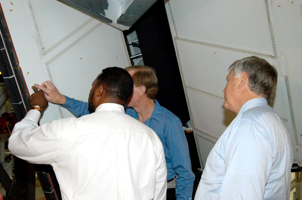
KENNEDY SPACE CENTER, FLA. - On a tour of the Orbiter Processing Facility, Deputy Director Woodrow Whitlow Jr. points to an area on a rudder speed brake panel on Endeavour that Tom Roberts, who is with United Space Alliance, is showing him. At right is Center Director Jim Kennedy. Endeavour is in its Orbiter Major Modification period, which began in December 2003.
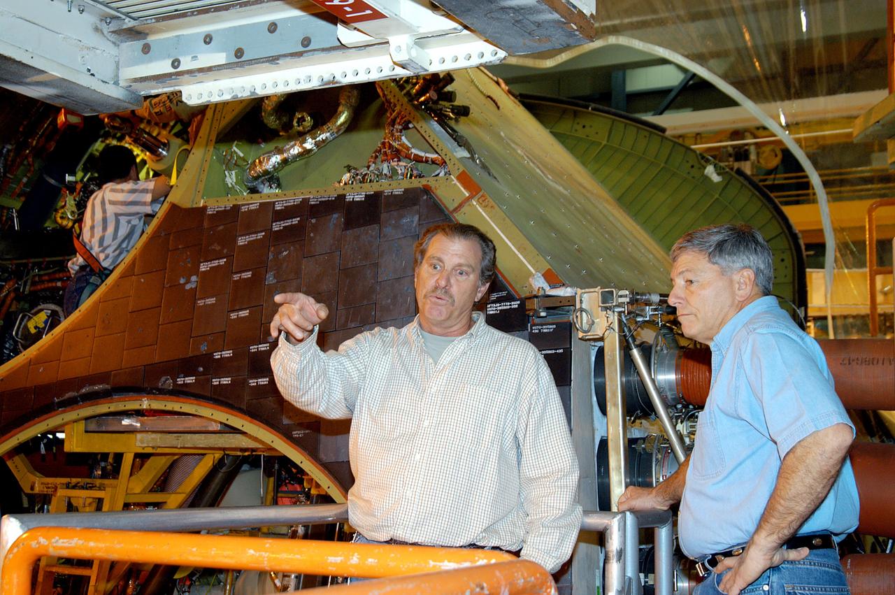
KENNEDY SPACE CENTER, FLA. -- NASA Deputy Associate Administrator for Space Station and Shuttle Programs Michael Kostelnik (right) discusses a speed brake on Shuttle Discovery in Orbiter Processing Facility Bay 3 with a United Space Alliance (USA) technician (left). NASA and USA Space Shuttle program management are participating in a leadership workday. The day is intended to provide management with an in-depth, hands-on look at Shuttle processing activities at KSC.
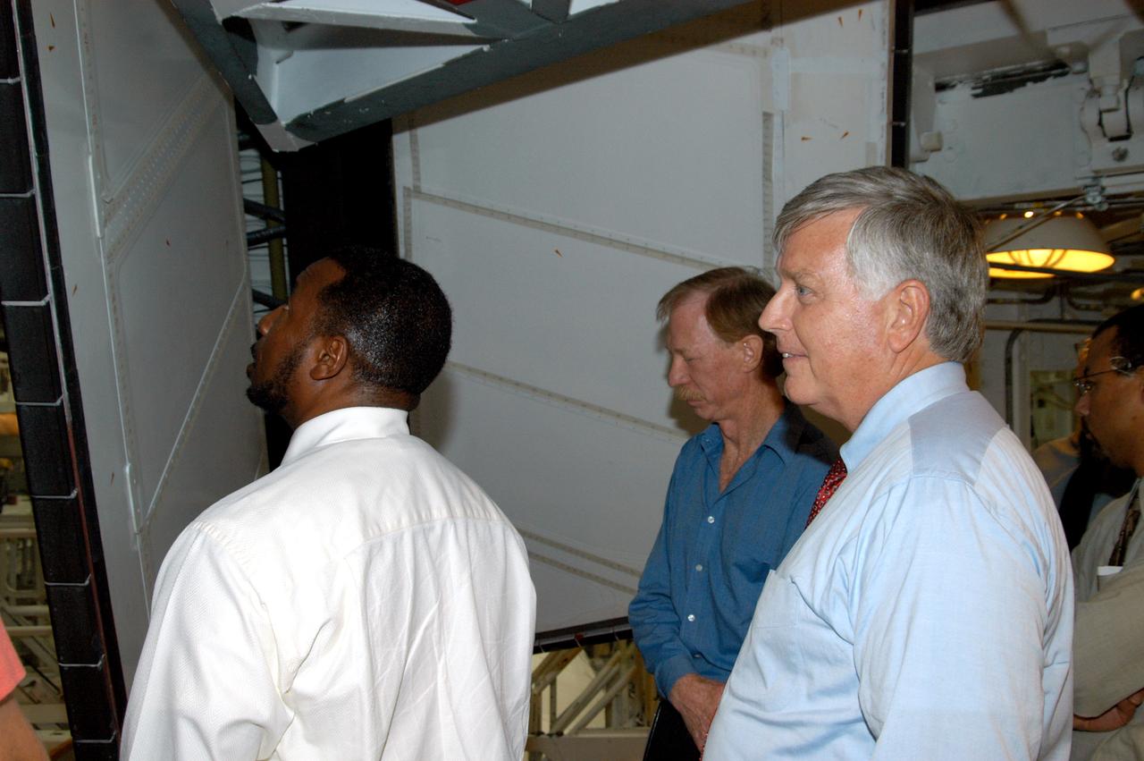
KENNEDY SPACE CENTER, FLA. - On a tour of the Orbiter Processing Facility, Center Director Jim Kennedy (right) and Deputy Director Woodrow Whitlow Jr. (left) look at rudder speed brake panels on Endeavour In the background is Tom Roberts, who is with United Space Alliance. Endeavour is in its Orbiter Major Modification period, which began in December 2003.
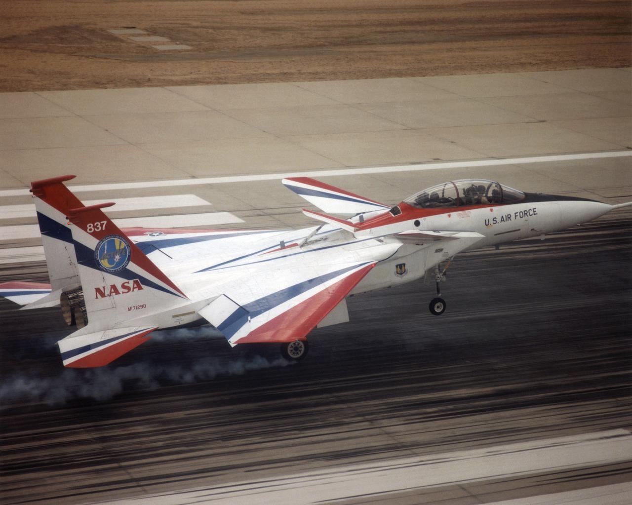
The F-15 ACTIVE touches down on the Edwards runway following its April 14, 1998 flight. The nose is high while the canards have their rear edge raised. the aircraft's speed brake, located on the top of the aircraft behind the canopy, is also raised.
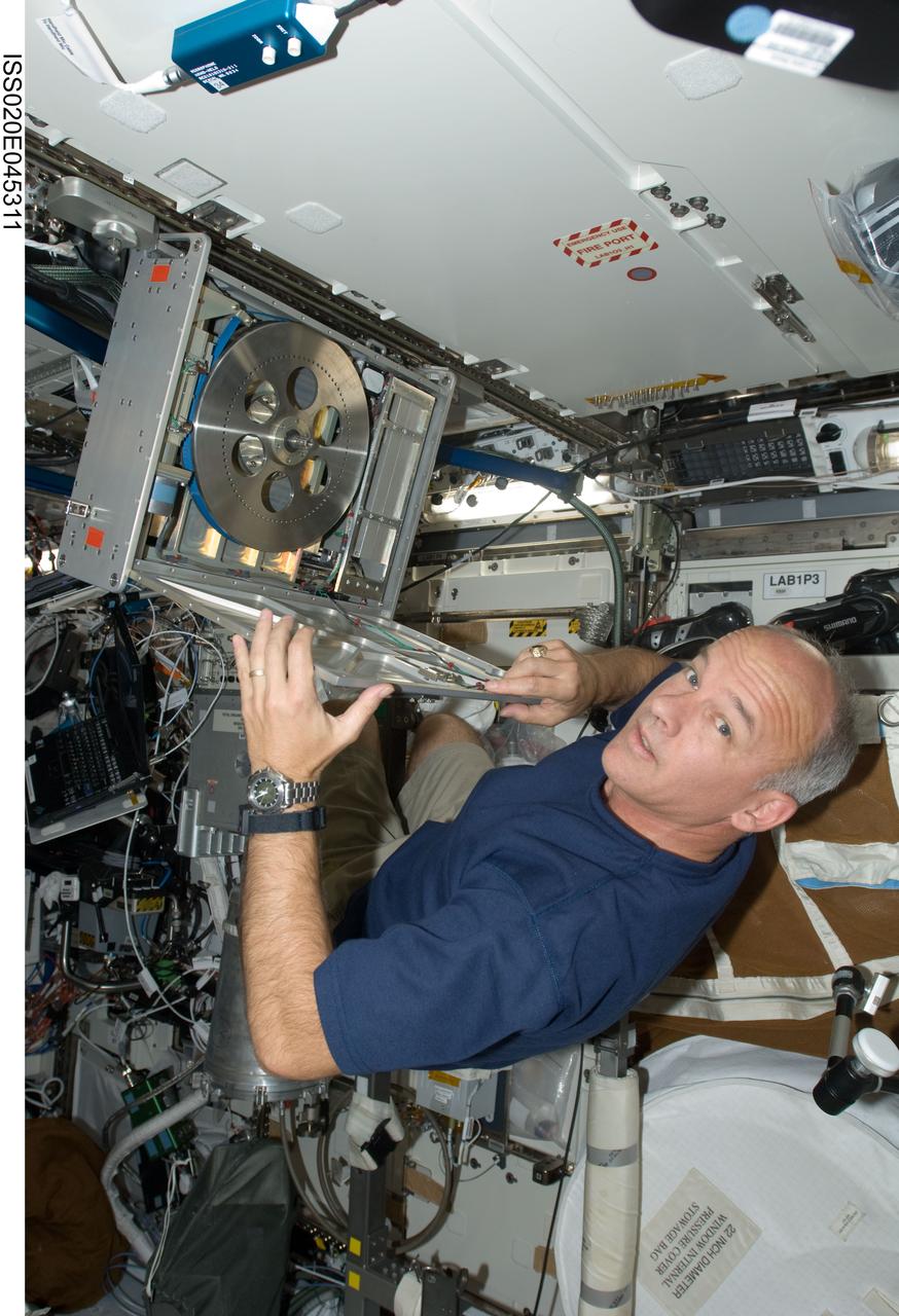
ISS020-E-045311 (5 Oct. 2009) --- NASA astronaut Jeffrey Williams, Expedition 21 flight engineer, performs in-flight maintenance (IFM) on the Cycle Ergometer with Vibration Isolation (CEVIS) braking band in the Destiny laboratory of the International Space Station.

KENNEDY SPACE CENTER, FLA. - A NASA quality inspector checks the placement of Rudder Speed Brake actuator No. 4 as work to install it on Space Shuttle orbiter Discovery nears completion in the Orbiter Processing Facility. Discovery has been assigned to the first Return to Flight mission, STS-114, a logistics flight to the International Space Station.

KENNEDY SPACE CENTER, FLA. - United Space Alliance technicians start the lift of Rudder Speed Brake actuator No. 4 to Space Shuttle orbiter Discovery in the Orbiter Processing Facility. Discovery has been assigned to the first Return to Flight mission, STS-114, a logistics flight to the International Space Station.
KENNEDY SPACE CENTER, FLA. - Rudder Speed Brake actuator No. 4 is ready for installation on Space Shuttle orbiter Discovery in the Orbiter Processing Facility. Discovery has been assigned to the first Return to Flight mission, STS-114, a logistics flight to the International Space Station.
KENNEDY SPACE CENTER, FLA. - United Space Alliance technicians verify the alignment of Rudder Speed Brake actuator No.4 as it is attached to Space Shuttle orbiter Discovery in the Orbiter Processing Facility. Discovery has been assigned to the first Return to Flight mission, STS-114, a logistics flight to the International Space Station.
KENNEDY SPACE CENTER, FLA. - A United Space Alliance technician monitors Rudder Speed Brake actuator No. 4 as it is moved into position for installation on Space Shuttle orbiter Discovery in the Orbiter Processing Facility. Discovery has been assigned to the first Return to Flight mission, STS-114, a logistics flight to the International Space Station.
KENNEDY SPACE CENTER, FLA. - United Space Alliance technicians check out Rudder Speed Brake actuator No. 4 before installing it on Space Shuttle orbiter Discovery in the Orbiter Processing Facility. Discovery has been assigned to the first Return to Flight mission, STS-114, a logistics flight to the International Space Station.
KENNEDY SPACE CENTER, FLA. - A United Space Alliance technician monitors the placement of Rudder Speed Brake actuator No.4 as work proceeds to install it on Space Shuttle orbiter Discovery in the Orbiter Processing Facility. Discovery has been assigned to the first Return to Flight mission, STS-114, a logistics flight to the International Space Station.
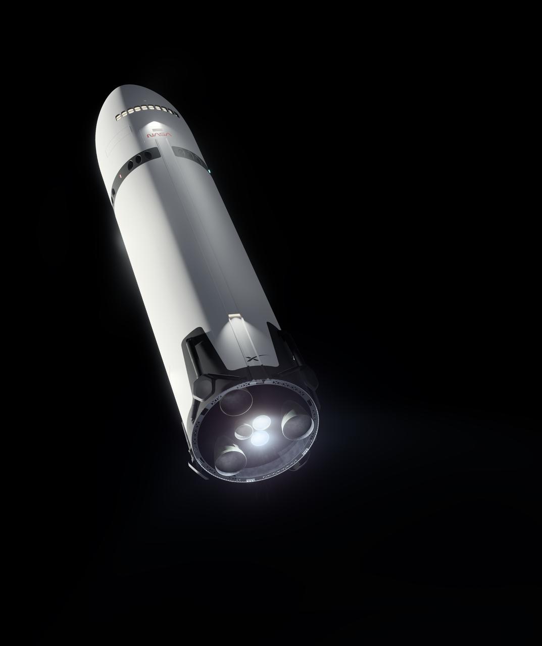
This artist’s concept portrays SpaceX’s Starship Human Landing System (HLS) with two Raptor engines lit, performing a braking burn prior to its Moon landing. The burn will occur after Starship HLS departs low lunar orbit to reduce the lander’s velocity prior to final descent to the lunar surface. NASA is working with SpaceX to develop Starship HLS to carry astronauts from lunar orbit to the Moon’s surface and back for Artemis III and Artemis IV as part of the agency’s Artemis campaign.

Here is an image of the X-59’s 13-foot General Electric F414 engine as the team prepares for a fit check. Making sure components, like the aircraft’s hydraulic lines, which help control functions like brakes or landing gear, and wiring of the engine, fit properly is essential to the aircraft’s safety. Once complete, the X-59 aircraft will demonstrate the ability to fly supersonic while reducing the loud sonic boom to a quiet sonic thump and help enable commercial supersonic air travel over land.
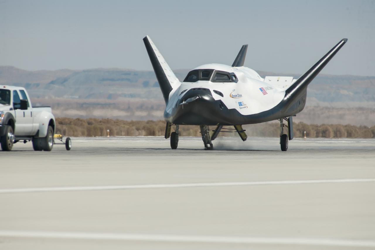
Edwards, Calif. – ED13-0266-066- A pickup truck releases the Sierra Nevada Corporation, or SNC, Dream Chaser flight vehicle during a 60 mile per hour tow test to validate the spacecraft's brakes on taxi and runways at NASA's Dryden Flight Research Center at Edwards Air Force Base in California. Ground testing at 10, 20, 40 and 60 miles per hour is helping the company validate the performance of the spacecraft's braking and landing systems prior to captive-carry and free-flight tests scheduled for later this year. SNC is continuing the development of its Dream Chaser spacecraft under the agency's Commercial Crew Development Round 2, or CCDev2, and Commercial Crew Integrated Capability, or CCiCap, phases, which are intended to lead to the availability of commercial human spaceflight services for government and commercial customers. To learn more about CCP and its industry partners, visit www.nasa.gov/commercialcrew. Image credit: NASA/Ken Ulbrich

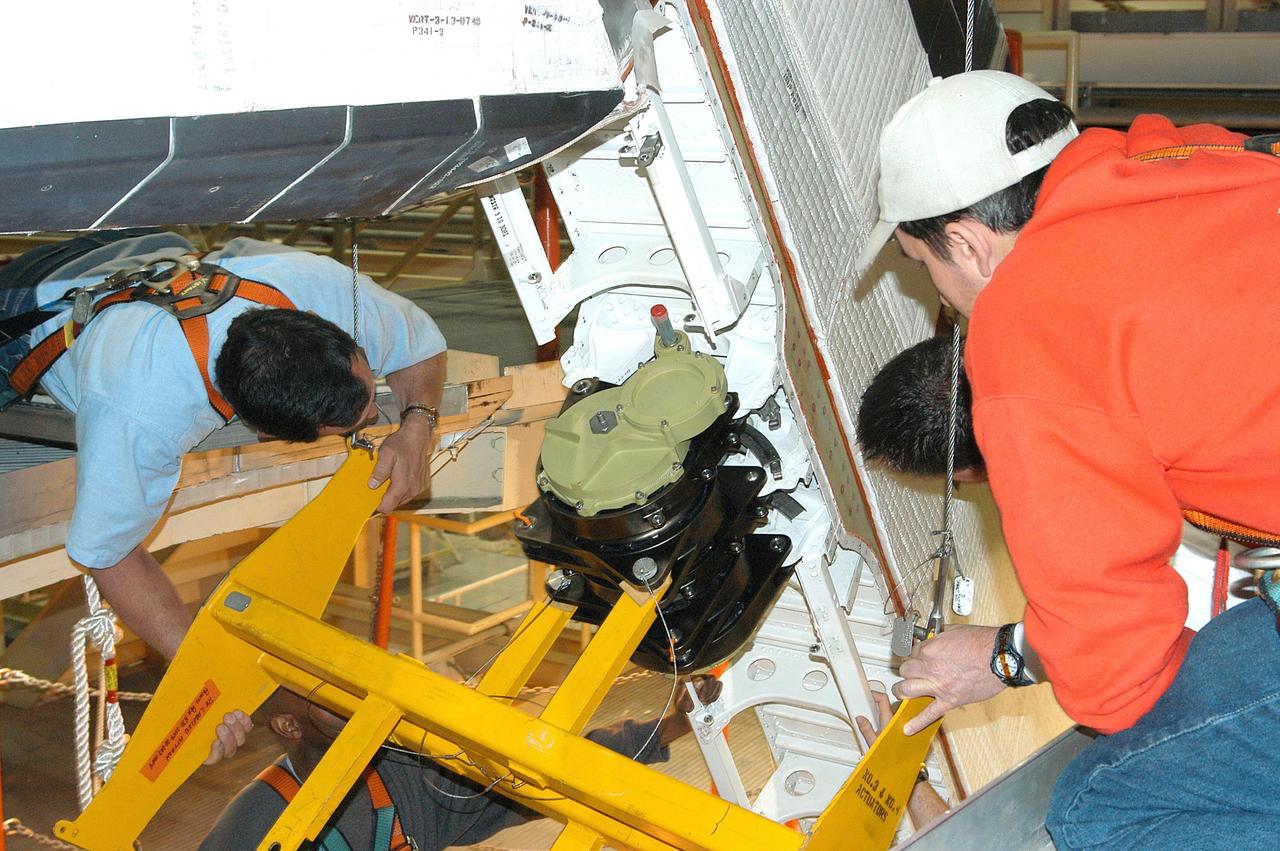
KENNEDY SPACE CENTER, FLA. -- At Launch Pad 39A, workers help guide the replacement Power Drive Unit (PDU) for Space Shuttle Atlantis into place. The PDU controls the rudder/speed brake on the orbiter. Atlantis is scheduled to lift off April 24 at 4:15 p.m. EDT on mission STS-101, the third flight to the International Space Station. The primary mission is to carry logistics and supplies to the Space Station, plus the crew will be preparing the Station for the arrival of the Zvezda Service Module, expected to be launched by Russia in July 2000

ISS026-E-028490 (20 Feb. 2011) --- Backdropped by a blue and white part of Earth, the unpiloted ISS Progress 39 supply vehicle appears to be very small as it departs from the International Space Station at 8:12 a.m. (EST) on Feb. 20, 2011. At 11:12 a.m., the deorbit burn braked the trash-loaded cargo ship into its re-entry trajectory over the Pacific Ocean, where it was burned up in Earth’s atmosphere.
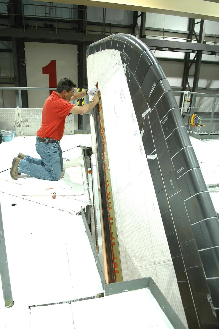
KENNEDY SPACE CENTER, FLA. - In the Orbiter Processing Facility at NASA’s Kennedy Space Center, United Space Alliance tile technician Jimmy Carter works on instrument wire spot bonding on Atlantis’ vertical tail_rudder speed brake. Atlantis is being processed for launch on the second Return to Flight mission, STS-121, which is scheduled to fly in July.
KENNEDY SPACE CENTER, FLA. - One of four rudder speed brake actuators is lifted for transfer to a pallet where it will be X-rayed. The actuators, to be installed on the orbiter Discovery, are being X-rayed at the Radiographic High-Energy X-ray Facility at Cape Canaveral Air Force Station to determine if the gears were installed correctly. Discovery has been assigned to the first Return to Flight mission, STS-114, a logistics flight to the International Space Station.
KENNEDY SPACE CENTER, FLA. - In the Orbiter Processing Facility at NASA’s Kennedy Space Center, United Space Alliance tile technician Jimmy Carter works on instrument wire spot bonding on Atlantis’ vertical tail_rudder speed brake. Atlantis is being processed for launch on the second Return to Flight mission, STS-121, which is scheduled to fly in July.
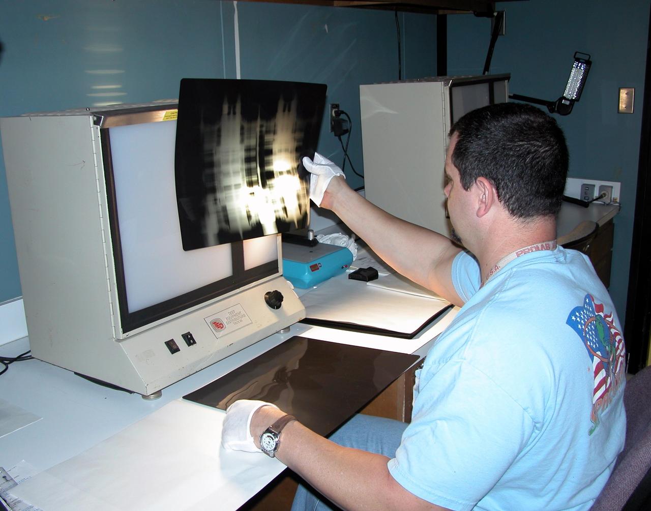
KENNEDY SPACE CENTER, FLA. - A technician at Cape Canaveral Air Force Station’s Radiographic High-Energy X-ray Facility looks at an X-ray of one of the four rudder speed brake actuators to be installed on the orbiter Discovery. The actuators are being X-rayed to determine if the gears were installed correctly. Discovery has been assigned to the first Return to Flight mission, STS-114, a logistics flight to the International Space Station.
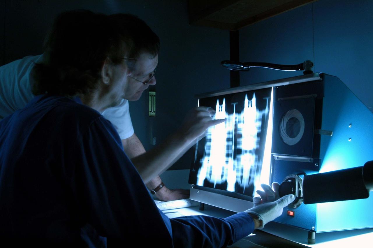
KENNEDY SPACE CENTER, FLA. - - While adjusting the image, technicians at Cape Canaveral Air Force Station’s Radiographic High-Energy X-ray Facility look at X-rays taken of one of the rudder speed brake actuators to be installed on the orbiter Discovery. The four actuators are being X-rayed to determine if the gears were installed correctly. Discovery has been assigned to the first Return to Flight mission, STS-114, a logistics flight to the International Space Station.
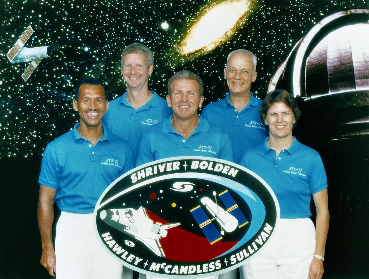
The STS-31 crew of five included (left to right) Charles F. Bolden, pilot; Steven A. Hawley, mission specialist; Loren J. Shriver, commander; Bruce McCandless, mission specialist; and Kathryn D. Sullivan, mission specialist. Launched aboard the Space Shuttle Discovery on April 24, 1990 at 8:33:51am (EDT), the primary payload was the Hubble Space Telescope. This was the first flight to use carbon brakes at landing.
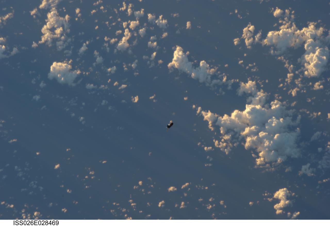
ISS026-E-028469 (20 Feb. 2011) --- Backdropped by a blue and white part of Earth, the unpiloted ISS Progress 39 supply vehicle appears to be very small as it departs from the International Space Station at 8:12 a.m. (EST) on Feb. 20, 2011. At 11:12 a.m., the deorbit burn braked the trash-loaded cargo ship into its re-entry trajectory over the Pacific Ocean, where it was burned up in Earth’s atmosphere.

KENNEDY SPACE CENTER, FLA. -- At Launch Pad 39A, workers move the replacement Power Drive Unit (PDU) into the body of Space Shuttle Atlantis. The PDU controls the rudder/speed brake on the orbiter. Atlantis is scheduled to lift off April 24 at 4:15 p.m. EDT on mission STS-101, the third flight to the International Space Station. The primary mission is to carry logistics and supplies to the Space Station, plus the crew will be preparing the Station for the arrival of the Zvezda Service Module, expected to be launched by Russia in July 2000
KENNEDY SPACE CENTER, FLA. -- In the Orbiter Processing Facility, STS-114 crew members look at one of the Rudder Speed Brake actuators. Seen at right are Mission Specialist Charles Camarda, Mission Commander Eileen Collins and Mission Specialist Wendy Lawrence. Crew members are touring several areas on Center. The STS-114 mission is Logistics Flight 1, which is scheduled to deliver supplies and equipment plus the external stowage platform to the International Space Station.
KENNEDY SPACE CENTER, FLA. - In the Orbiter Processing Facility, seen here is the vertical stabilizer on the orbiter Discovery. On the edge of the stabilizer are the four Rudder Speed Brake Actuators recently installed. Below is the engine number 1 interface. Discovery has been assigned to the first Return to Flight mission, STS-114, a logistics flight to the International Space Station.
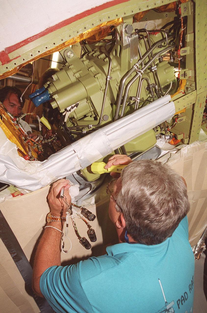
At Launch Pad 39A, Greg Lohning, who is with NASA, inspects the wiring on the newly installed Power Drive Unit (PDU) in Space Shuttle Atlantis. The PDU controls the rudder/speed brake on the orbiter. Atlantis is scheduled to lift off April 24 at 4:15 p.m. EDT on mission STS-101, the third flight to the International Space Station. The primary mission is to carry logistics and supplies to the Space Station, plus the crew will be preparing the Station for the arrival of the Zvezda Service Module, expected to be launched by Russia in July 2000
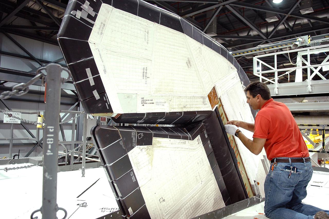
KENNEDY SPACE CENTER, FLA. - In the Orbiter Processing Facility at NASA’s Kennedy Space Center, United Space Alliance tile technician Tim Marks places Thermal Protection System tiles on Atlantis’ rudder speed brake. Atlantis is being processed for launch on the second Return to Flight mission, STS-121, which is scheduled to fly in July.
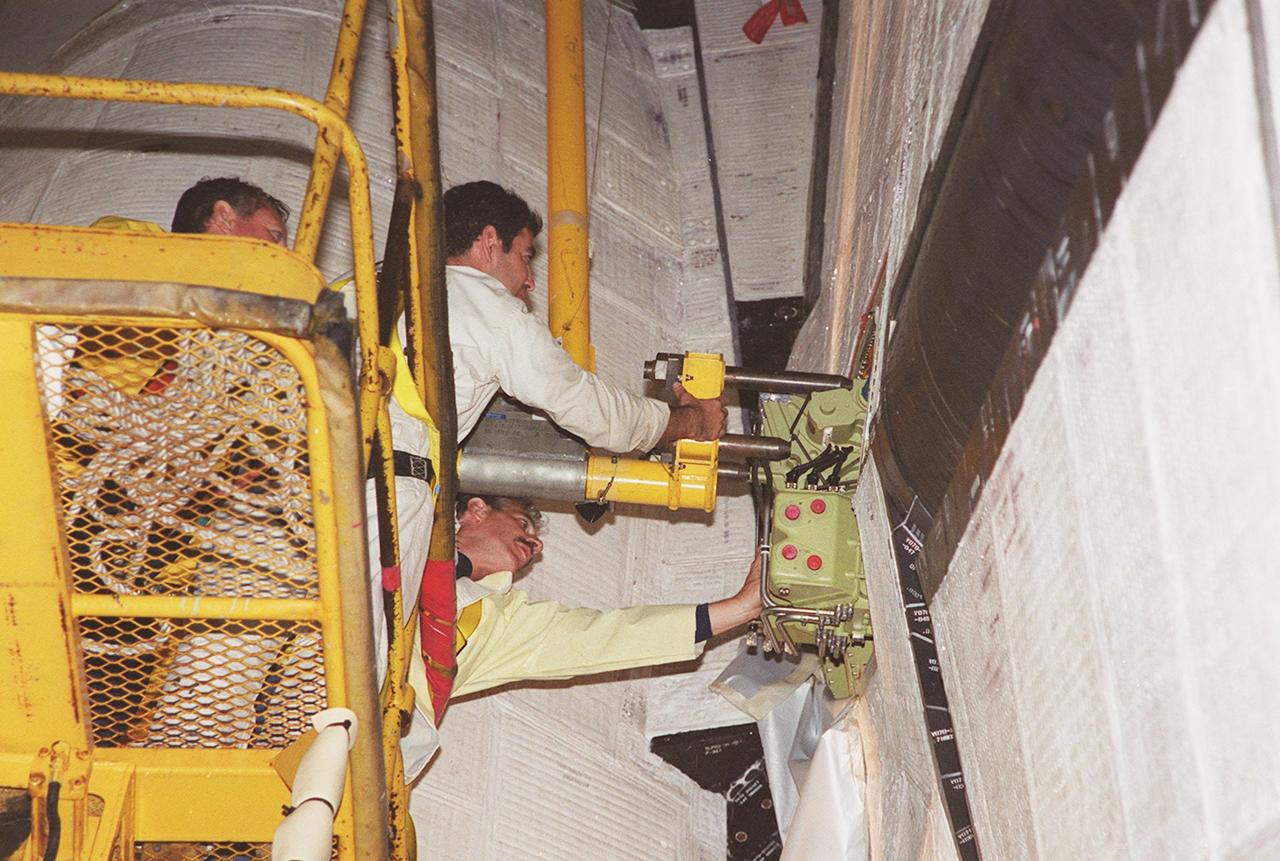
KENNEDY SPACE CENTER, FLA. -- At Launch Pad 39A, workers move the replacement Power Drive Unit (PDU) into the body of Space Shuttle Atlantis. The PDU controls the rudder/speed brake on the orbiter. Atlantis is scheduled to lift off April 24 at 4:15 p.m. EDT on mission STS-101, the third flight to the International Space Station. The primary mission is to carry logistics and supplies to the Space Station, plus the crew will be preparing the Station for the arrival of the Zvezda Service Module, expected to be launched by Russia in July 2000
KENNEDY SPACE CENTER, FLA. -- At Launch Pad 39A, workers help guide the replacement Power Drive Unit (PDU) for Space Shuttle Atlantis into place. The PDU controls the rudder/speed brake on the orbiter. Atlantis is scheduled to lift off April 24 at 4:15 p.m. EDT on mission STS-101, the third flight to the International Space Station. The primary mission is to carry logistics and supplies to the Space Station, plus the crew will be preparing the Station for the arrival of the Zvezda Service Module, expected to be launched by Russia in July 2000
The US Air Force loaned a Republic F-84 Thunderjet to the National Advisory Committee for Aeronautics (NACA) Lewis Flight Propulsion Laboratory in the spring of 1954. NACA researchers soon modified the aircraft for the first demonstration of a reverse thruster. Republic built over 4000 Thunderjets between 1947 and 1953 for the military as a successor to the Lockheed F-80 Shooting Star. TheF-84s became successful multi-use aircraft during the Korean War. The use of traditional wheel brakes on high speed aircraft was problematic because the required braking system would weigh too much. The reverse thruster was developed as a method for stopping these aircraft without increasing the overall weight. Panels in the tail section near the jet engine’s nozzle opened up during a landing. These extended flaps not only caused resistance to the airstream but also reversed the engine’s thrust. In June 1964 Irving Pinkel, head of the Lewis Physics Division, oversaw a demonstration of this technology on an F-84 at the NACA laboratory. The side fuselage panels around the engine nozzle, seen closed in this photograph, opened up like wings and deflected the engine’s thrust towards the front of the aircraft, thus producing reverse thrust. The F-84 activated the reverse thruster and the aircraft moved backwards across the runway.
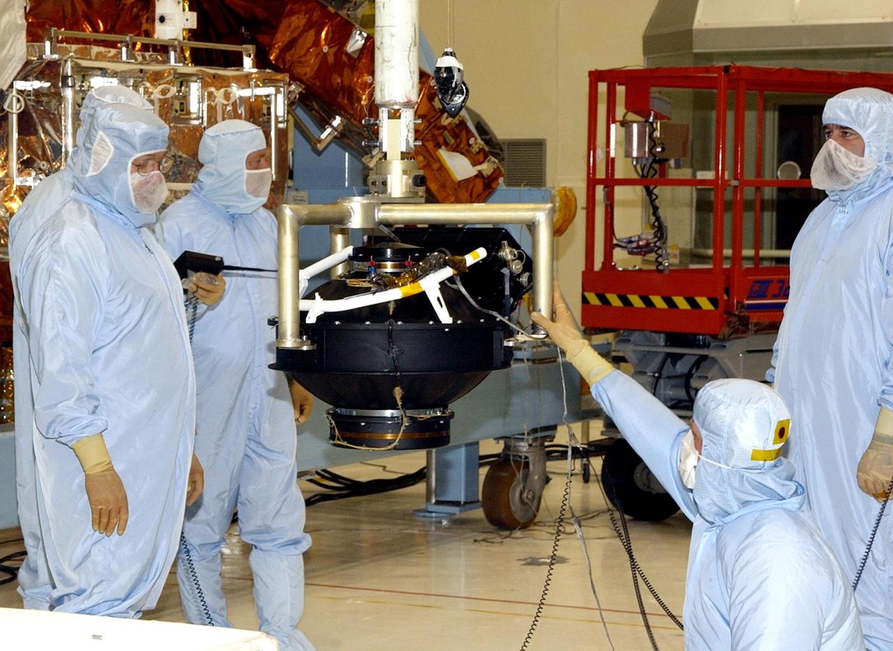
KENNEDY SPACE CENTER, FLA. - In the Vertical Processing Facility, the replacement Reaction Wheel Actuator for the Hubble Space Telescope is moved from its shipping container. Part of Hubble's Pointing Control System, the actuators receiving information from sensors and physically adjust Hubble's position and orientation so that Hubble can view the required celestial bodies. The reaction wheels work by rotating a large flywheel up to 3000 rpm or braking it to exchange momentum with the spacecraft which will make Hubble turn. The RWA is part of the payload on mission STS-109, the Hubble Servicing Mission, scheduled to launch Feb. 28, 2002
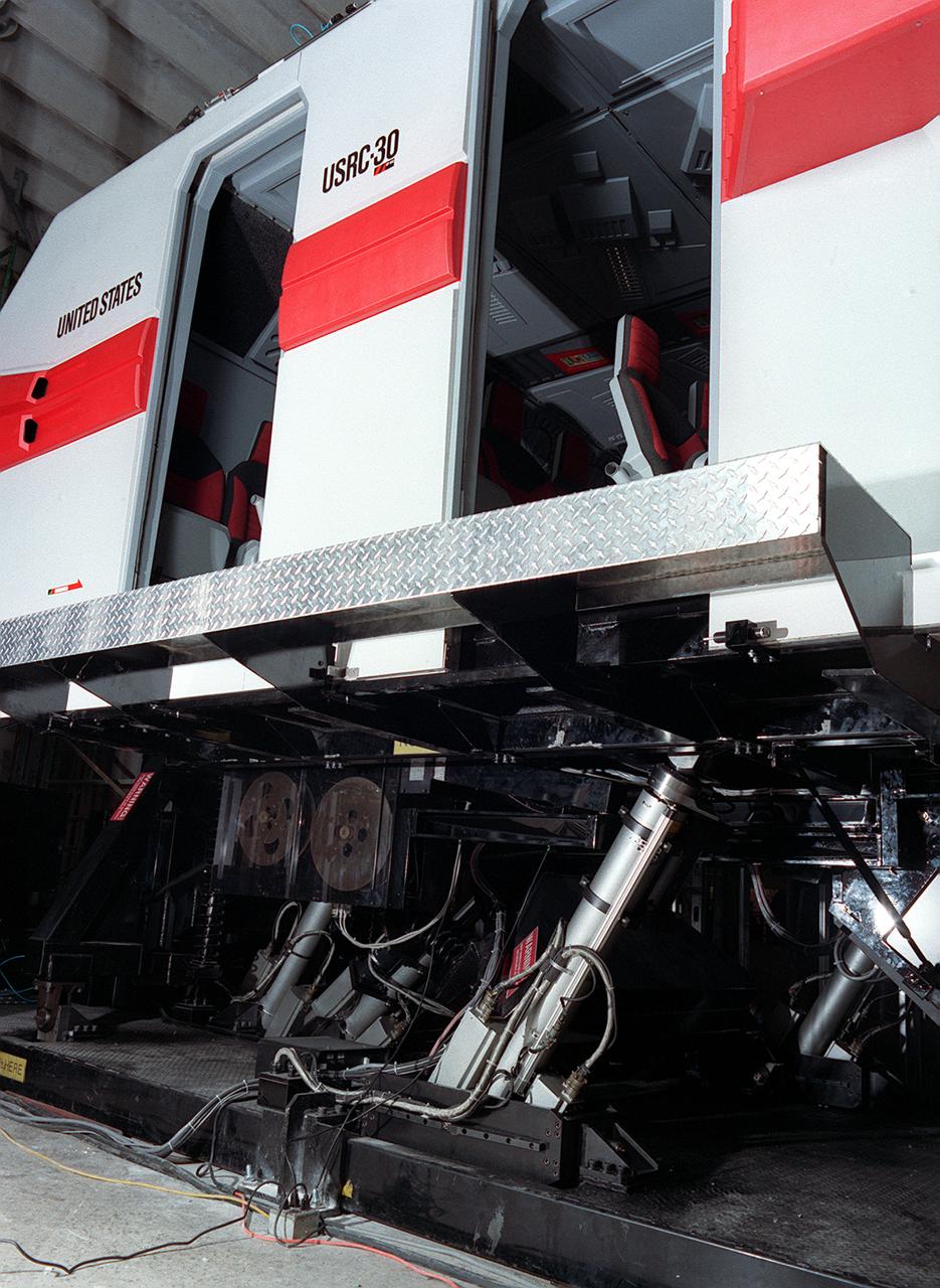
The development of the electric space actuator represents an unusual case of space technology transfer wherein the product was commercialized before it was used for the intended space purpose. MOOG, which supplies the thrust vector control hydraulic actuators for the Space Shuttle and brake actuators for the Space Orbiter, initiated development of electric actuators for aerospace and industrial use in the early 1980s. NASA used the technology to develop an electric replacement for the Space Shuttle main engine TVC actuator. An electric actuator is used to take passengers on a realistic flight to Jupiter at the US Space and Rocket Center, Huntsville, Alabama.
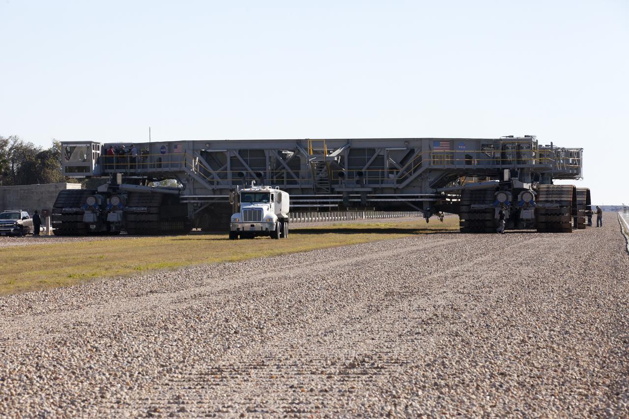
Crawler-transport 2 (CT-2) moves slowly along the crawlerway on its way back to the Vehicle Assembly Building at NASA's Kennedy Space Center in Florida. The crawler took a trip to the pad A/B split to test upgrades recently completed that will allow the giant vehicle to handle the load of the agency's Space Launch System rocket and Orion spacecraft atop the mobile launcher. The Ground Systems Development and Operations Program oversaw upgrades to the 50-year-old CT-2. New generators, gear assemblies, jacking, equalizing and leveling (JEL) hydraulic cylinders, roller bearings and brakes were installed, and other components were upgraded to prepare for Exploration Mission 1.

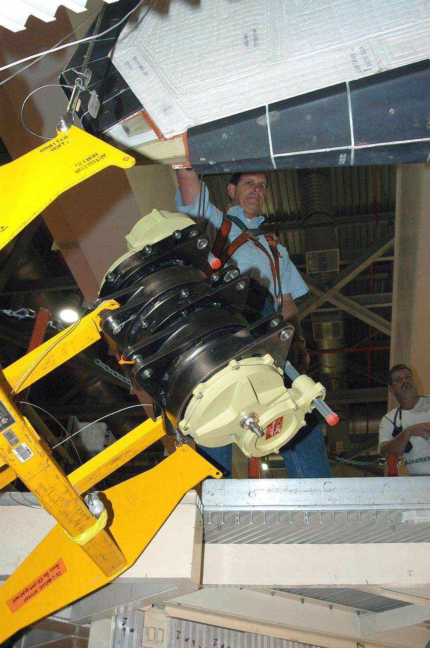
KENNEDY SPACE CENTER, FLA. -- At Launch Pad 39A, a worker reaches toward the plastic-covered replacement Power Drive Unit (PDU) for Space Shuttle Atlantis as it is lifted by crane toward the tail. The PDU controls the rudder/speed brake on the orbiter. Atlantis is scheduled to lift off April 24 at 4:15 p.m. EDT on mission STS-101, the third flight to the International Space Station. The primary mission is to carry logistics and supplies to the Space Station, plus the crew will be preparing the Station for the arrival of the Zvezda Service Module, expected to be launched by Russia in July 2000
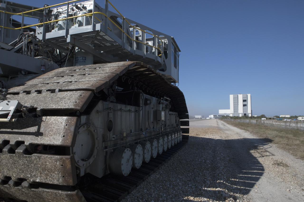
Crawler-transporter 2 (CT-2) moves slowly along the crawlerway toward the Vehicle Assembly Building (in the background) at NASA's Kennedy Space Center in Florida. The crawler took a trip to the Pad A/B split to test upgrades recently completed that will allow the giant vehicle to handle the load of the agency's Space Launch System rocket and Orion spacecraft atop the mobile launcher. The Ground Systems Development and Operations Program oversaw upgrades to the 50-year-old CT-2. New generators, gear assemblies, jacking, equalizing and leveling (JEL) hydraulic cylinders, roller bearings and brakes were installed, and other components were upgraded to prepare for Exploration Mission 1.
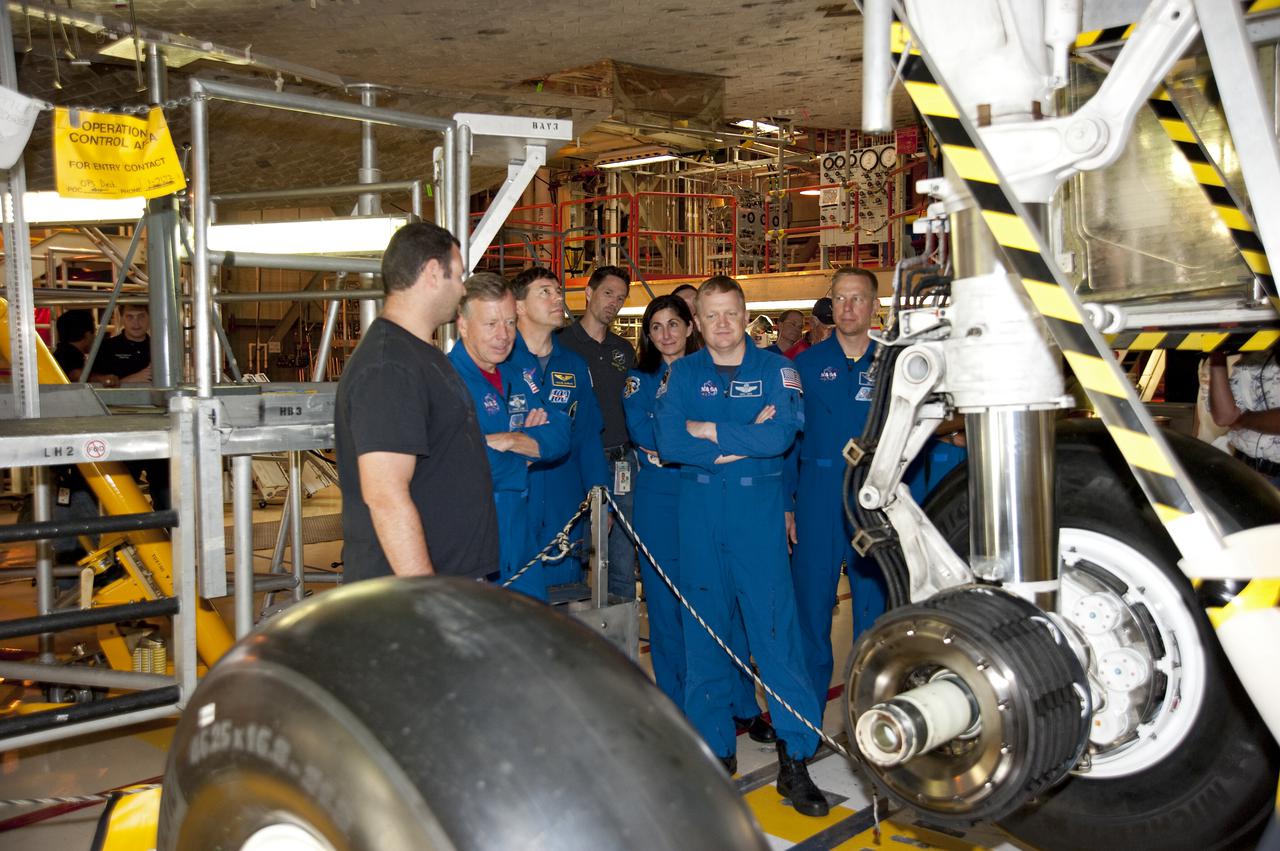
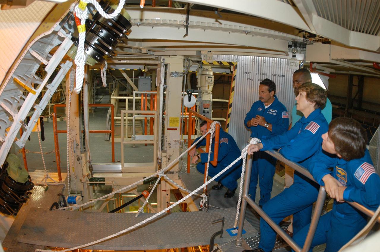
CAPE CANAVERAL, Fla. -- In Orbiter Processing Facility-3 at NASA's Kennedy Space Center in Florida, a technician discusses the shuttle's braking system to the STS-133 crew members. Pictured are Commander Steve Lindsey (left), Mission Specialist Michael Barratt, Nicole Stott; Pilot Eric Boe and Mission Specialist Tim Kopra. The astronauts are at Kennedy for the Crew Equipment Interface Test, or CEIT, which provides the crew with hands-on training and observation of shuttle and flight hardware for their mission to the International Space Station. Launch of the STS-133 mission on space shuttle Discovery is targeted for Nov. 1 at 4:33 p.m. EDT. Photo credit: NASA_Kim Shiflett

KENNEDY SPACE CENTER, FLA. -- At Launch Pad 39A, a worker watches as the plastic-covered replacement Power Drive Unit (PDU) for Space Shuttle Atlantis is lifted by crane toward the tail. The PDU controls the rudder/speed brake on the orbiter. Atlantis is scheduled to lift off April 24 at 4:15 p.m. EDT on mission STS-101, the third flight to the International Space Station. The primary mission is to carry logistics and supplies to the Space Station, plus the crew will be preparing the Station for the arrival of the Zvezda Service Module, expected to be launched by Russia in July 2000
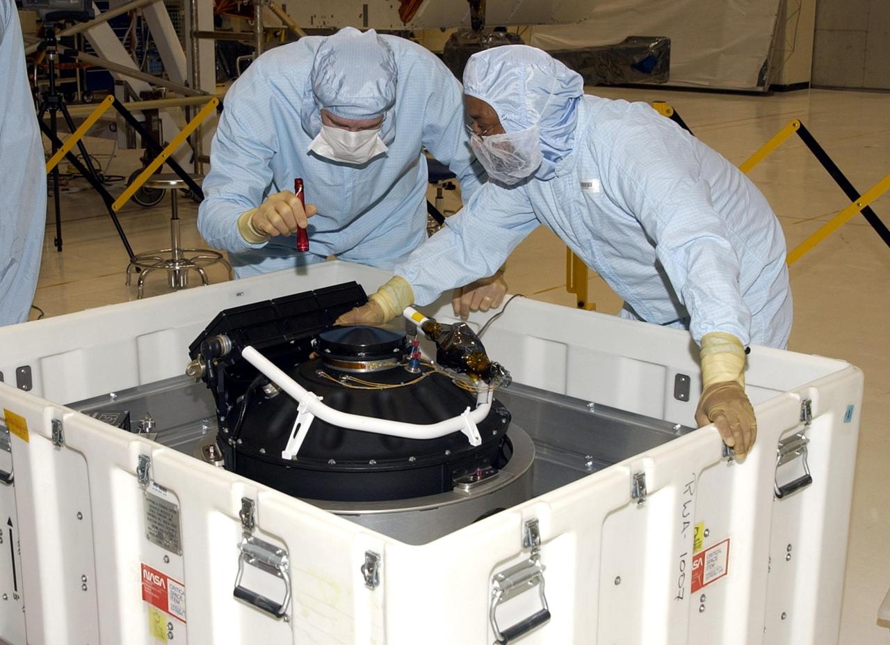
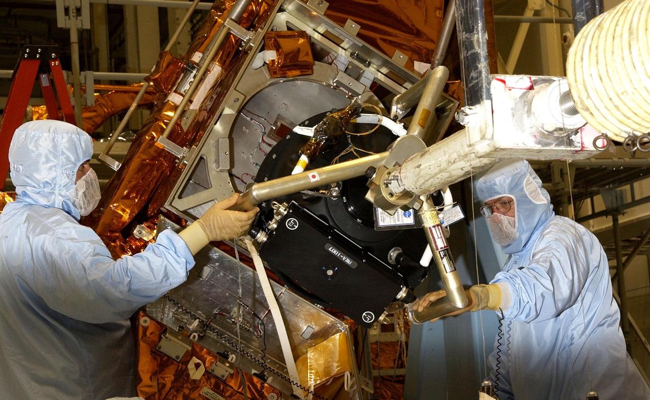
KENNEDY SPACE CENTER, FLA. -- The replacement Reaction Wheel Actuator for the Hubble Space Telescope arrives at the Vertical Processing Facility. Part of Hubble's Pointing Control System, the actuators receiving information from sensors and physically adjust Hubble's position and orientation so that Hubble can view the required celestial bodies. The reaction wheels work by rotating a large flywheel up to 3000 rpm or braking it to exchange momentum with the spacecraft which will make Hubble turn. The RWA is part of the payload on mission STS-109, the Hubble Servicing Mission, scheduled to launch Feb. 28, 2002
KENNEDY SPACE CENTER, FLA. - Workers in the Vertical Processing Facility check the position of the Hubble Space Telescope's replacement Reaction Wheel Actuator on the Large Orbital Protective Enclosure (LOPE), which is contained in the Multi-Use Lightweight Equipment (MULE) for flight. Part of Hubble's Pointing Control System, the actuators receiving information from sensors and physically adjust Hubble's position and orientation so that Hubble can view the required celestial bodies. The reaction wheels work by rotating a large flywheel up to 3000 rpm or braking it to exchange momentum with the spacecraft which will make Hubble turn. The RWA is part of the payload on mission STS-109, the Hubble Servicing Mission, scheduled to launch Feb. 28, 2002

KENNEDY SPACE CENTER, FLA. -- At Launch Pad 39A, workers wait to begin replace Shuttle Atlantis' Power Drive Unit (PDU), which is attached to the crane (center). The PDU controls the rudder/speed brake on the orbiter. Atlantis is scheduled to lift off April 24 at 4:15 p.m. EDT on mission STS-101, the third flight to the International Space Station. The primary mission is to carry logistics and supplies to the Space Station, plus the crew will be preparing the Station for the arrival of the Zvezda Service Module, expected to be launched by Russia in July 2000
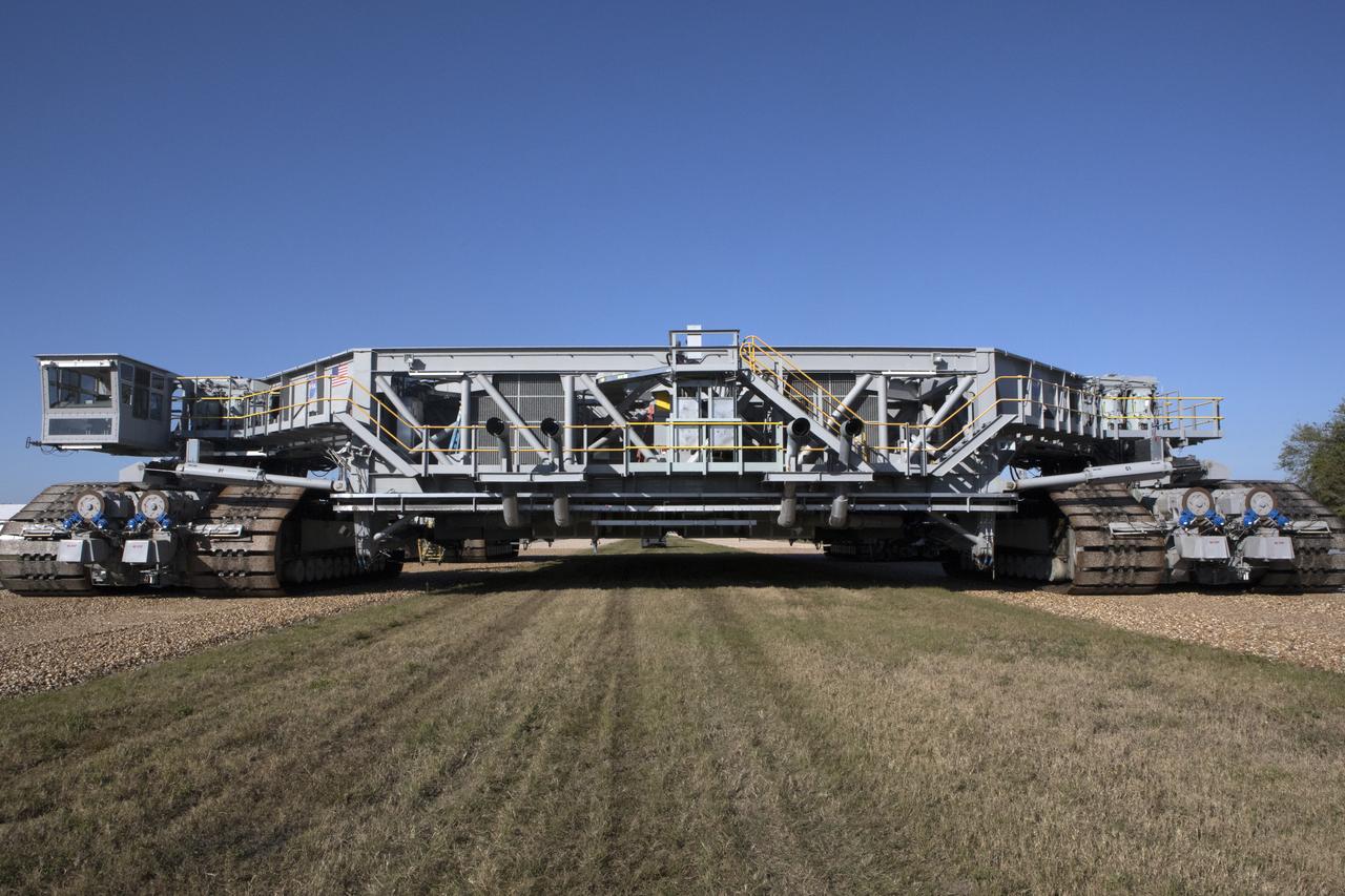
A full view of crawler-transporter 2 (CT-2) as it moves slowly along the crawlerway on its way back to the Vehicle Assembly Building at NASA's Kennedy Space Center in Florida. The crawler took a trip to the Pad A/B split to test upgrades recently completed that will allow the giant vehicle to handle the load of the agency's Space Launch System rocket and Orion spacecraft atop the mobile launcher. The Ground Systems Development and Operations Program oversaw upgrades to the 50-year-old CT-2. New generators, gear assemblies, jacking, equalizing and leveling (JEL) hydraulic cylinders, roller bearings and brakes were installed, and other components were upgraded to prepare for Exploration Mission 1.
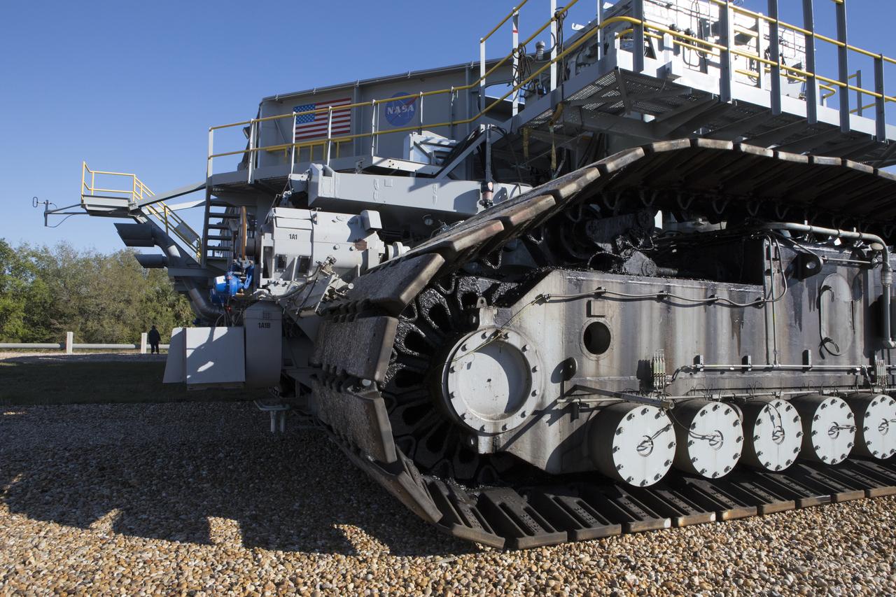
Crawler-transporter 2 (CT-2) moves slowly along the crawlerway on its way back to the Vehicle Assembly Building at NASA's Kennedy Space Center in Florida. The crawler took a trip to the Pad A/B split to test upgrades recently completed that will allow the giant vehicle to handle the load of the agency's Space Launch System rocket and Orion spacecraft atop the mobile launcher. The Ground Systems Development and Operations Program oversaw upgrades to the 50-year-old CT-2. New generators, gear assemblies, jacking, equalizing and leveling (JEL) hydraulic cylinders, roller bearings and brakes were installed, and other components were upgraded to prepare for Exploration Mission 1.
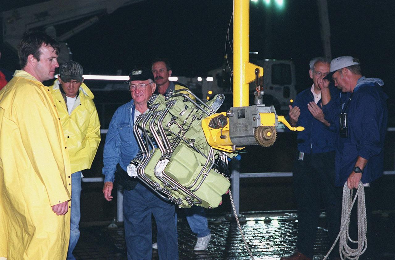
KENNEDY SPACE CENTER, FLA. -- At Launch Pad 39A, workers wait to begin replace Shuttle Atlantis' Power Drive Unit (PDU), which is attached to the crane (center). The PDU controls the rudder/speed brake on the orbiter. Atlantis is scheduled to lift off April 24 at 4:15 p.m. EDT on mission STS-101, the third flight to the International Space Station. The primary mission is to carry logistics and supplies to the Space Station, plus the crew will be preparing the Station for the arrival of the Zvezda Service Module, expected to be launched by Russia in July 2000
KENNEDY SPACE CENTER, FLA. - Workers in the Vertical Processing Facility maneuver the replacement Reaction Wheel Actuator for the Hubble Space Telescope into position on the Large Orbital Protective Enclosure (LOPE), which is contained in the Multi-Use Lightweight Equipment (MULE) for flight. Part of Hubble's Pointing Control System, the actuators receiving information from sensors and physically adjust Hubble's position and orientation so that Hubble can view the required celestial bodies. The reaction wheels work by rotating a large flywheel up to 3000 rpm or braking it to exchange momentum with the spacecraft which will make Hubble turn. The RWA is part of the payload on mission STS-109, the Hubble Servicing Mission, scheduled to launch Feb. 28, 2002
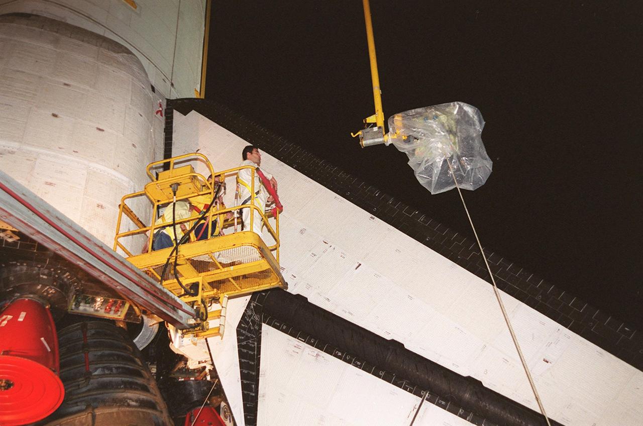
KENNEDY SPACE CENTER, FLA. -- At Launch Pad 39A, a worker watches as the plastic-covered replacement Power Drive Unit (PDU) for Space Shuttle Atlantis is lifted by crane toward the tail. The PDU controls the rudder/speed brake on the orbiter. Atlantis is scheduled to lift off April 24 at 4:15 p.m. EDT on mission STS-101, the third flight to the International Space Station. The primary mission is to carry logistics and supplies to the Space Station, plus the crew will be preparing the Station for the arrival of the Zvezda Service Module, expected to be launched by Russia in July 2000
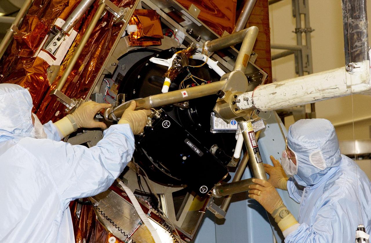
KENNEDY SPACE CENTER, FLA. - Workers in the Vertical Processing Facility check the position of the Hubble Space Telescope's replacement Reaction Wheel Actuator on the Large Orbital Protective Enclosure (LOPE), which is contained in the Multi-Use Lightweight Equipment (MULE) for flight. Part of Hubble's Pointing Control System, the actuators receiving information from sensors and physically adjust Hubble's position and orientation so that Hubble can view the required celestial bodies. The reaction wheels work by rotating a large flywheel up to 3000 rpm or braking it to exchange momentum with the spacecraft which will make Hubble turn. The RWA is part of the payload on mission STS-109, the Hubble Servicing Mission, scheduled to launch Feb. 28, 2002
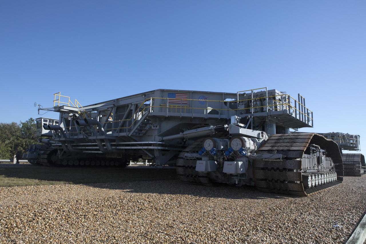
Crawler-transporter 2 (CT-2) moves slowly along the crawlerway on its way back to the Vehicle Assembly Building at NASA's Kennedy Space Center in Florida. The crawler took a trip to the Pad A/B split to test upgrades recently completed that will allow the giant vehicle to handle the load of the agency's Space Launch System rocket and Orion spacecraft atop the mobile launcher. The Ground Systems Development and Operations Program oversaw upgrades to the 50-year-old CT-2. New generators, gear assemblies, jacking, equalizing and leveling (JEL) hydraulic cylinders, roller bearings and brakes were installed, and other components were upgraded to prepare for Exploration Mission 1.
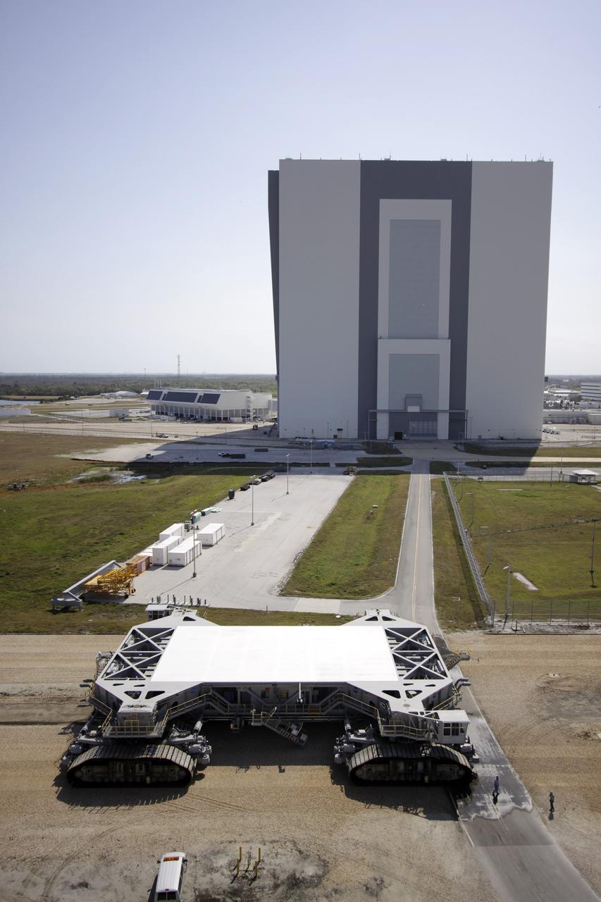
CAPE CANAVERAL, Fla. – At NASA’s Kennedy Space Center in Florida, the crawler-transporter 2, or CT-2, is on its way to the Park Site west of the Vehicle Assembly Building. The transporter has new brakes and mufflers and a recently-painted white roof deck. The Ground Systems Development and Operations Program office at Kennedy is overseeing the upgrades to CT-2 so that it can carry NASA’s Space Launch System heavy-lift rocket, which is under design, and new Orion spacecraft to the launch pad. The crawler-transporters were used to carry the mobile launcher platform and space shuttle to Launch Complex 39 for space shuttle launches for 30 years. Photo credit: NASA/Jim Grossmann
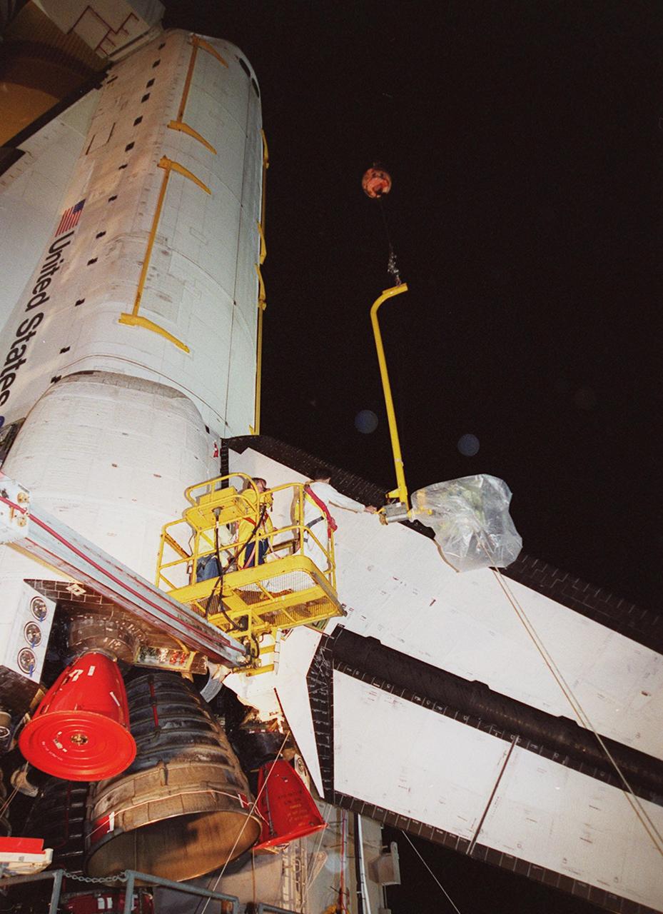
KENNEDY SPACE CENTER, FLA. -- At Launch Pad 39A, a worker reaches toward the plastic-covered replacement Power Drive Unit (PDU) for Space Shuttle Atlantis as it is lifted by crane toward the tail. The PDU controls the rudder/speed brake on the orbiter. Atlantis is scheduled to lift off April 24 at 4:15 p.m. EDT on mission STS-101, the third flight to the International Space Station. The primary mission is to carry logistics and supplies to the Space Station, plus the crew will be preparing the Station for the arrival of the Zvezda Service Module, expected to be launched by Russia in July 2000
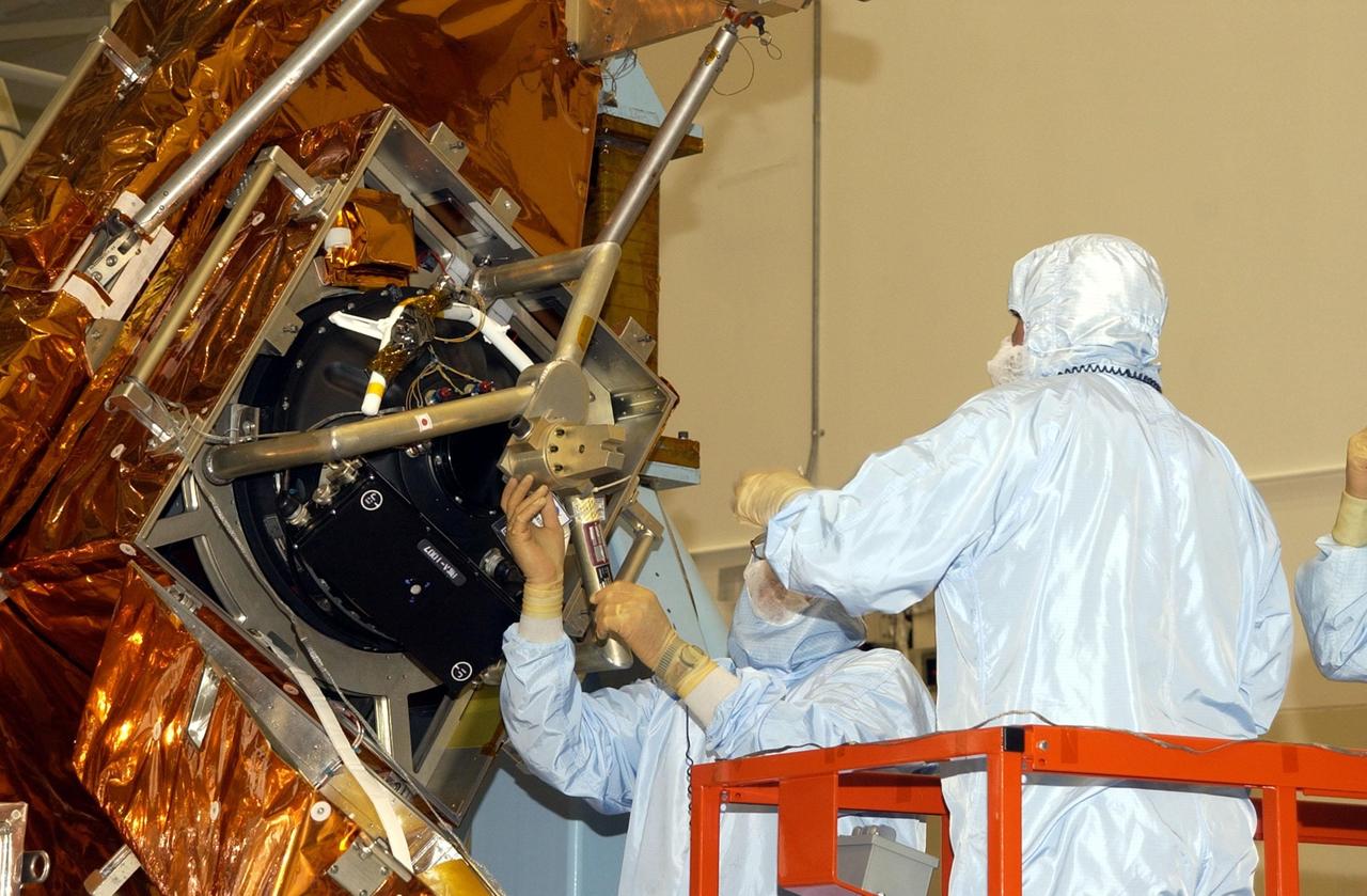
KENNEDY SPACE CENTER, FLA. -- Workers in the Vertical Processing Facility check the attachment of the the Hubble Space Telescope's replacement Reaction Wheel Actuator on the Large Orbital Protective Enclosure (LOPE), which is contained in the Multi-Use Lightweight Equipment (MULE) for flight. Part of Hubble's Pointing Control System, the actuators receiving information from sensors and physically adjust Hubble's position and orientation so that Hubble can view the required celestial bodies. The reaction wheels work by rotating a large flywheel up to 3000 rpm or braking it to exchange momentum with the spacecraft which will make Hubble turn. The RWA is part of the payload on mission STS-109, the Hubble Servicing Mission, scheduled to launch Feb. 28, 2002
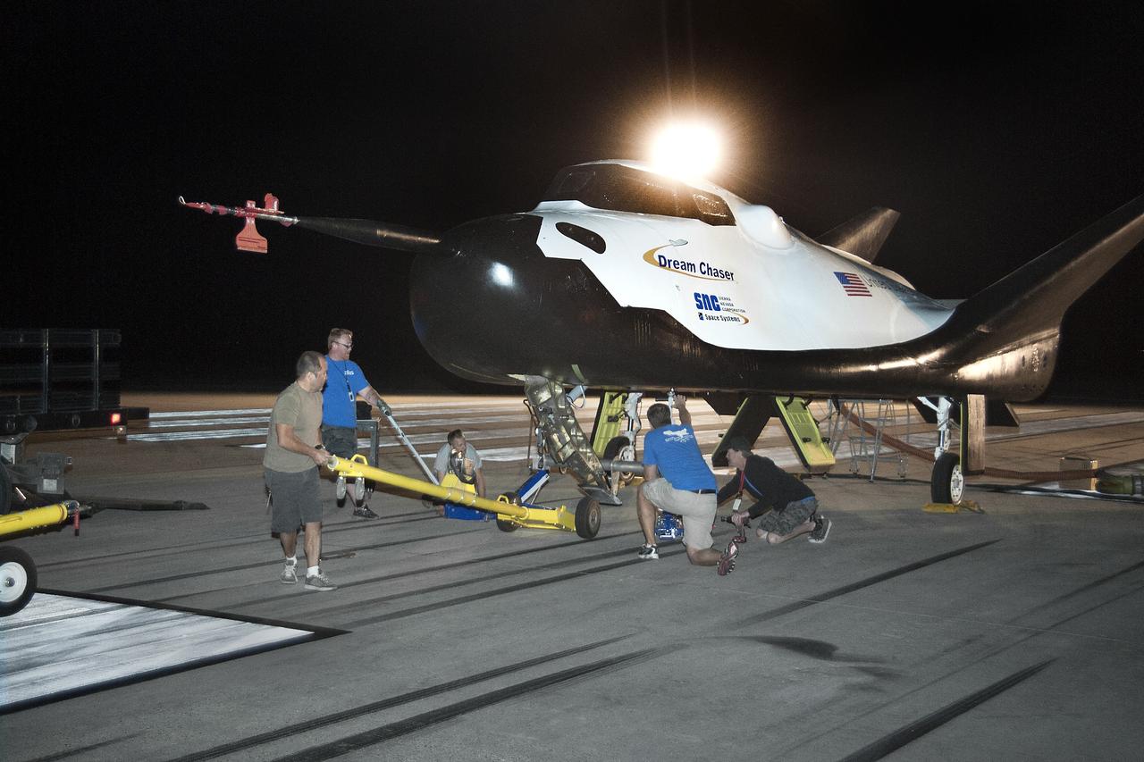
Edwards, Calif. – ED13-0266-013- Sierra Nevada Corporation, or SNC, team members prepare for 60 mph tow tests of the company's Dream Chaser flight vehicle on taxi and runways at NASA's Dryden Flight Research Center at Edwards Air Force Base in California. Ground testing at 10, 20, 40 and 60 miles per hour is helping the company validate the performance of the spacecraft's braking and landing systems prior to captive-carry and free-flight tests scheduled for later this year. SNC is continuing the development of its Dream Chaser spacecraft under the agency's Commercial Crew Development Round 2, or CCDev2, and Commercial Crew Integrated Capability, or CCiCap, phases, which are intended to lead to the availability of commercial human spaceflight services for government and commercial customers. To learn more about CCP and its industry partners, visit www.nasa.gov/commercialcrew. Image credit: NASA/Ken Ulbrich
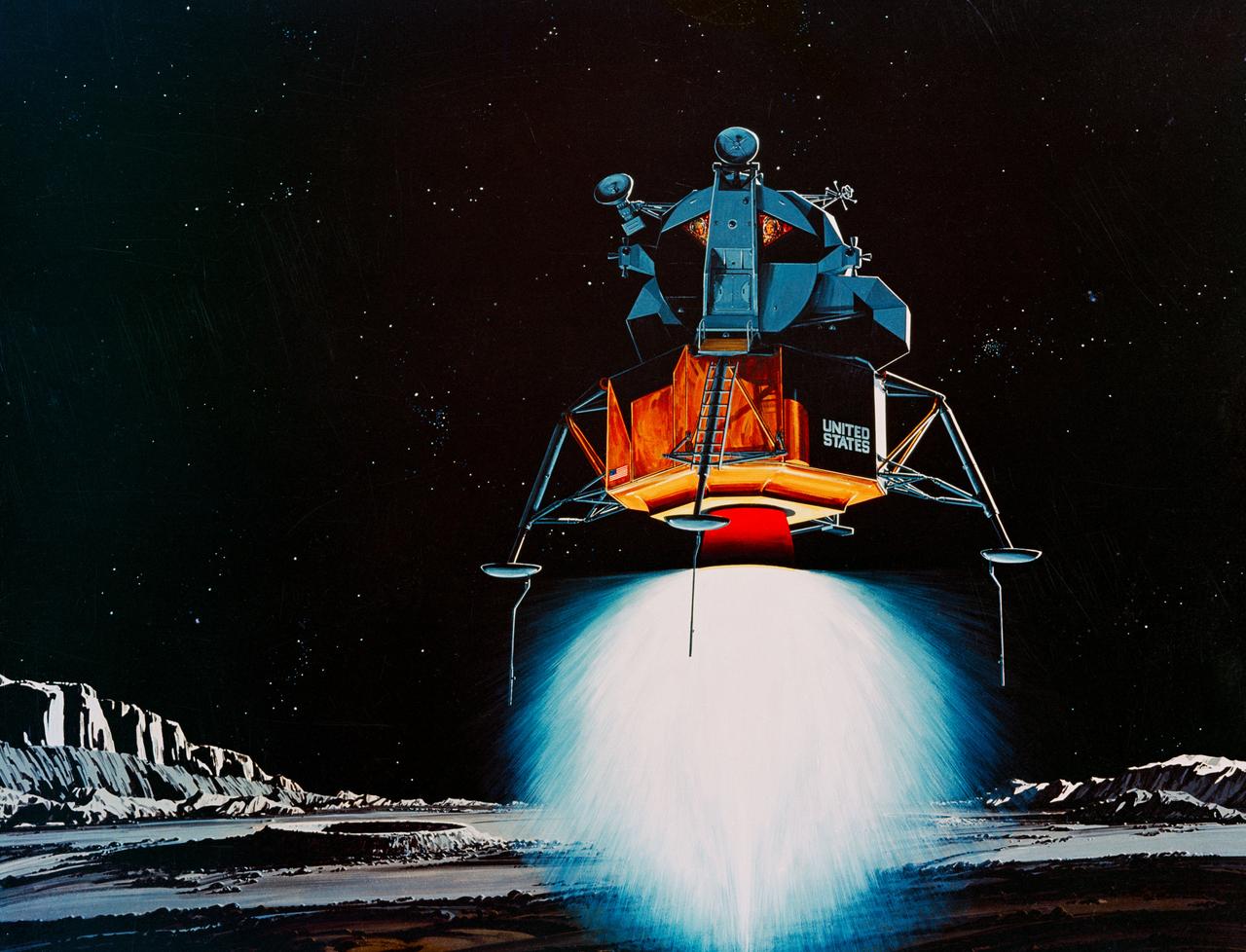
S69-39011 (July 1969) --- TRW Incorporated's artist concept depicting the Apollo 11 Lunar Module (LM) descending to the surface of the moon. Inside the LM will be astronauts Neil A. Armstrong, commander, and Edwin E. Aldrin Jr., lunar module pilot. Astronaut Michael Collins, command module pilot, will remain with the Command and Service Modules (CSM) in lunar orbit. TRW's LM descent engine will brake Apollo 11's descent to the lunar surface. The throttle-able rocket engine will be fired continuously the last 10 miles of the journey to the moon, slowing the LM to a speed of two miles per hour at touchdown. TRW Incorporated designed and built the unique engine at Redondo Beach, California under subcontract to the Grumman Aircraft Engineering Corporation, Bethpage, New York, the LM prime contractor.