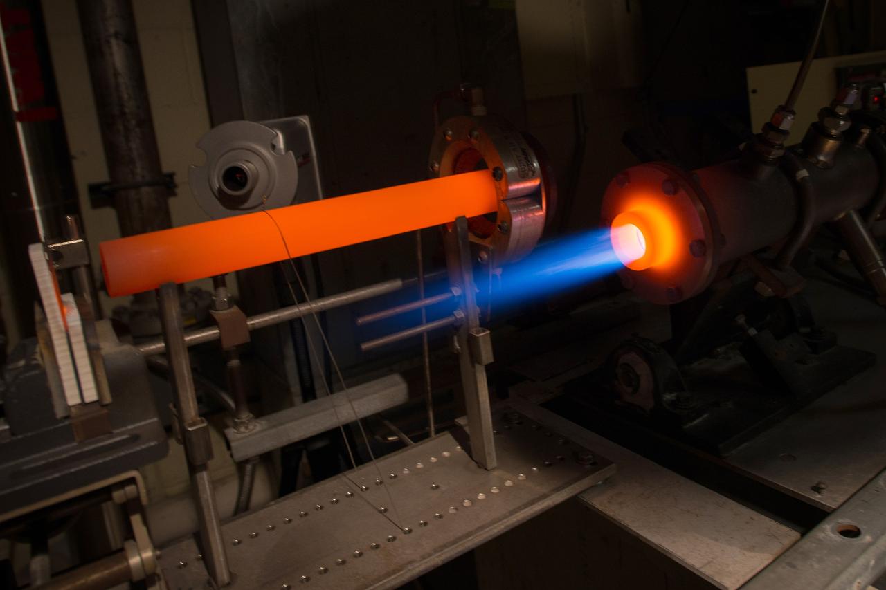
The Fuel Burner Rig is a test laboratory at NASA Glenn, which subjects new jet engine materials, treated with protective coatings, to the hostile, high temperature, high velocity environment found inside aircraft turbine engines. These samples face 200-mile per hour flames to simulate the temperatures of aircraft engines in flight. The rig can also simulate aircraft carrier and dusty desert operations where salt and sand can greatly reduce engine life and performance.
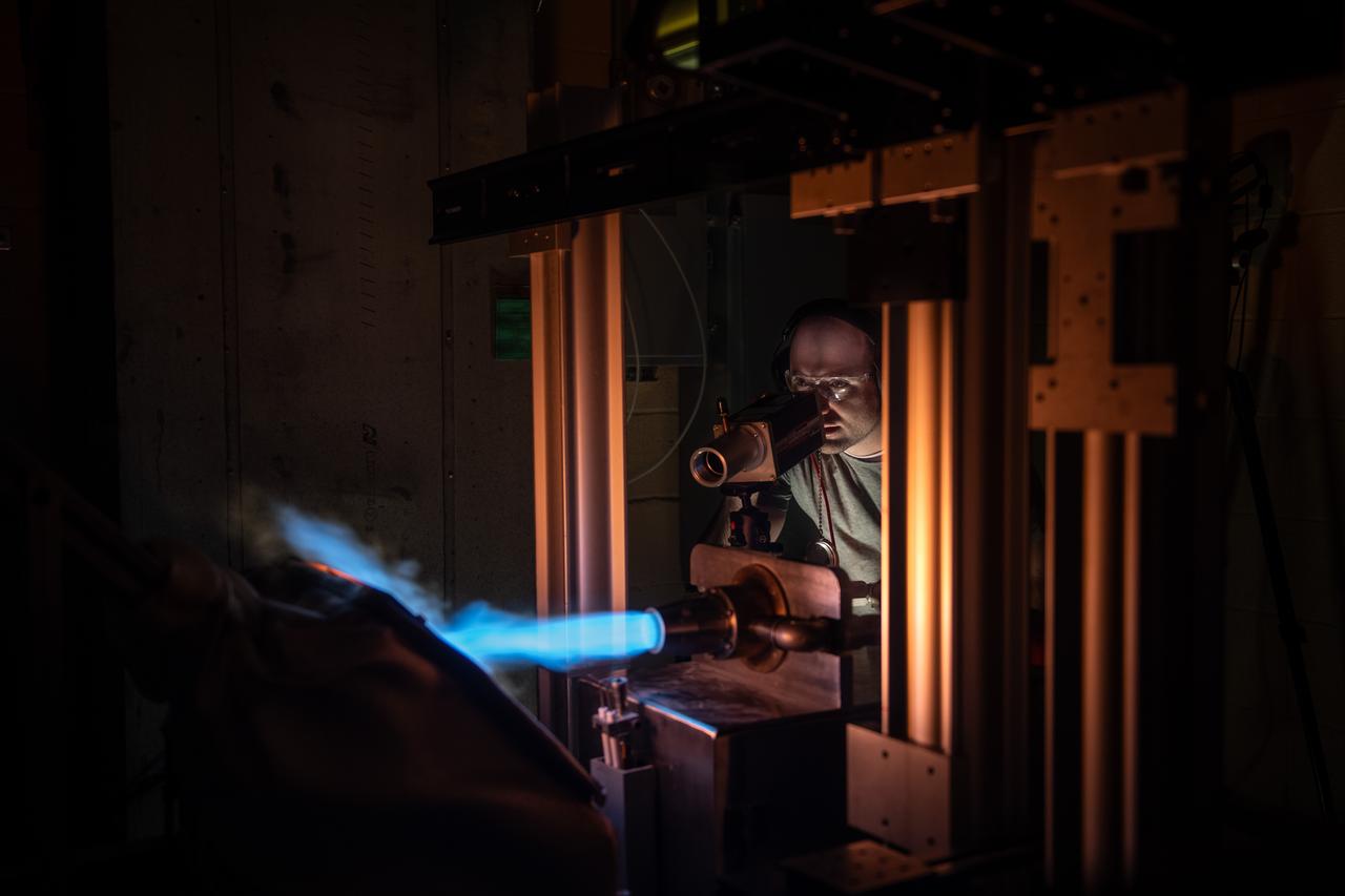
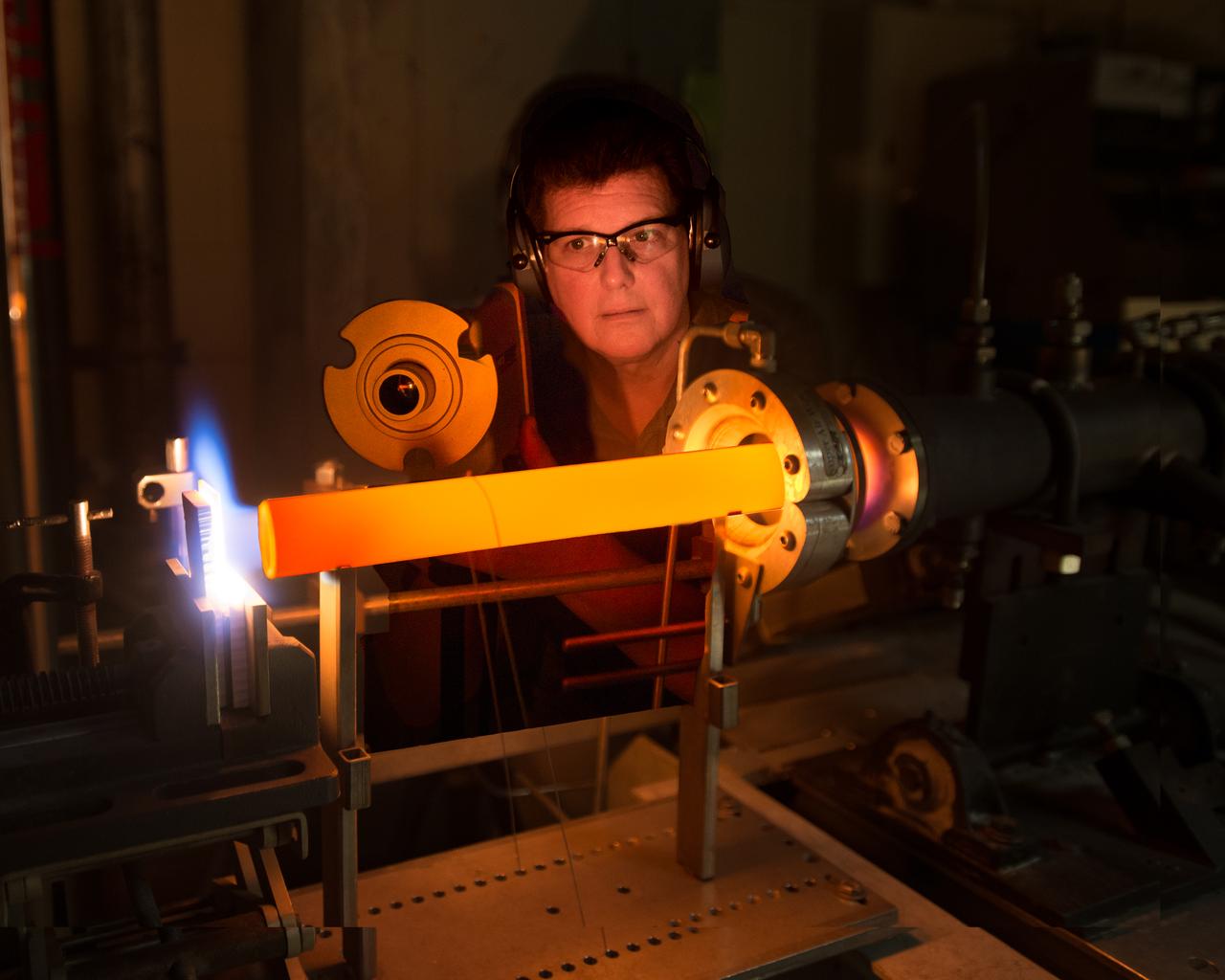
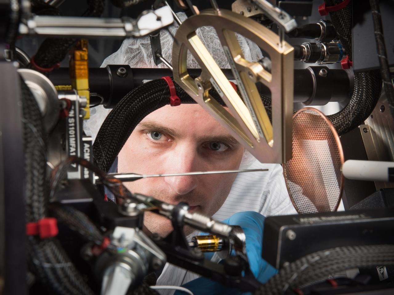
NASA Glenn’s Natural Gas/Oxygen Burner Rig is used to study the high temperature performance of various metal alloys, ceramics, and protective coatings for aero and space propulsion systems. The burner rig provides an easily accessible and economical method to simulate engine operating conditions to understand thermomechanical and thermochemical degradation of materials and structures. In the photo, Materials Research Engineer Michael Presby uses an infrared pyrometer to monitor the surface temperature of the material for a test on February 23, 2024. Photo Credit: (NASA/Sara Lowthian-Hanna)
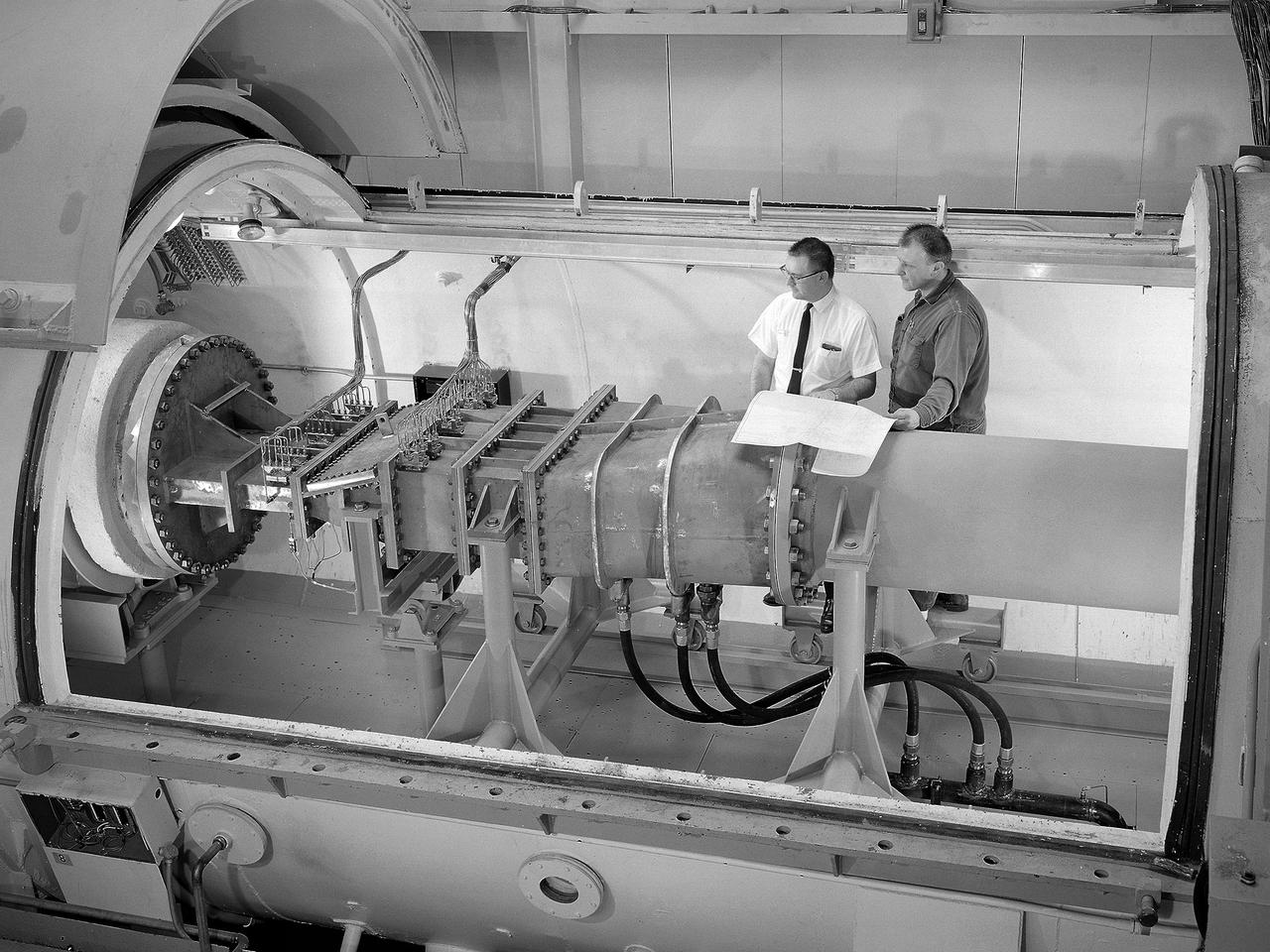
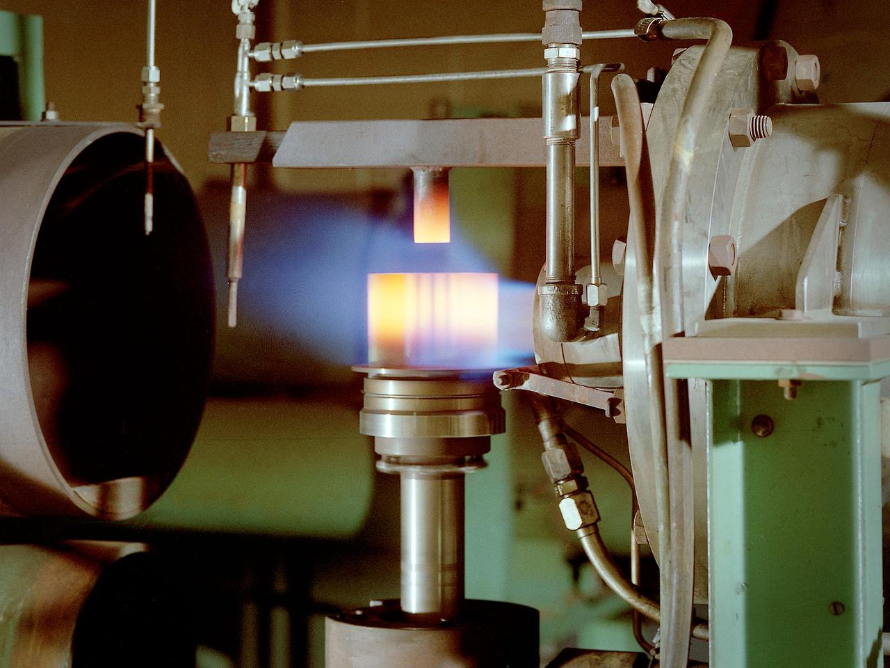
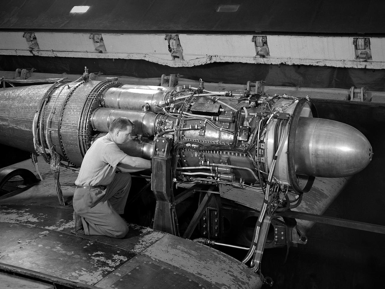
Engineer Frank Kutina and a National Aeronautics and Space Administration (NASA) mechanic examine the setup of an advanced combustor rig inside one of the test cells at the Lewis Research Center’s Four Burner Area in the Engine Research Building. Kutina, of the Research Operations Branch, served as go-between for the researchers and the mechanics. He helped develop the test configurations and get the hardware installed. At the time of this photograph, Lewis Center Director Abe Silverstein had just established the Airbreathing Engine Division to address the new propulsion of the 1960s. After nearly a decade of focusing almost exclusively on space, NASA Lewis began tackling issues relating to the new turbofan engine, noise reduction, energy efficiency, supersonic transport, and the never-ending quest for higher performance levels with smaller and more lightweight engines. The Airbreathing Engine Division’s Combustion Branch was dedicated to the study and mitigation of the high temperatures and pressures found in advanced combustor designs. These high temperatures and pressures could destroy engine components. The Lewis investigation included film cooling, diffuser flow, and jet mixing. Components were tested in smaller test cells, but a full-scale augmenting burner rig, seen here, was tested extensively in the Four Burner Area test cell.
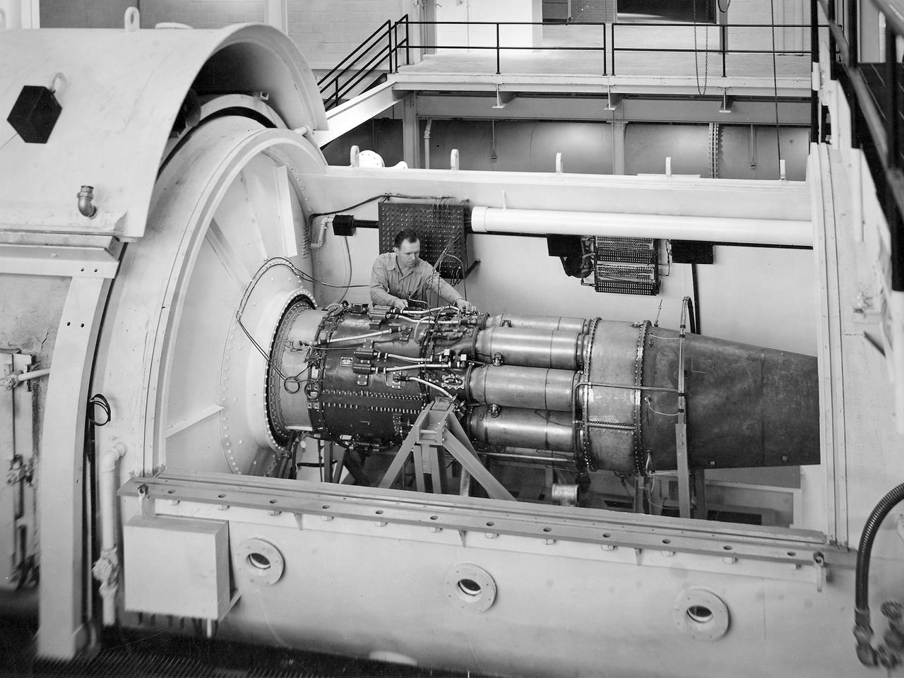
One of the two altitude simulating-test chambers in Engine Research Building at the National Advisory Committee for Aeronautics (NACA) Lewis Flight Propulsion Laboratory. The two chambers were collectively referred to as the Four Burner Area. NACA Lewis’ Altitude Wind Tunnel was the nation’s first major facility used for testing full-scale engines in conditions that realistically simulated actual flight. The wind tunnel was such a success in the mid-1940s that there was a backlog of engines waiting to be tested. The Four Burner chambers were quickly built in 1946 and 1947 to ease the Altitude Wind Tunnel’s congested schedule. The Four Burner Area was located in the southwest wing of the massive Engine Research Building, across the road from the Altitude Wind Tunnel. The two chambers were 10 feet in diameter and 60 feet long. The refrigeration equipment produced the temperatures and the exhauster equipment created the low pressures present at altitudes up to 60,000 feet. In 1947 the Rolls Royce Nene was the first engine tested in the new facility. The mechanic in this photograph is installing a General Electric J-35 engine. Over the next ten years, a variety of studies were conducted using the General Electric J-47 and Wright Aeronautical J-65 turbojets. The two test cells were occasionally used for rocket engines between 1957 and 1959, but other facilities were better suited to the rocket engine testing. The Four Burner Area was shutdown in 1959. After years of inactivity, the facility was removed from the Engine Research Building in late 1973 in order to create the High Temperature and Pressure Combustor Test Facility.
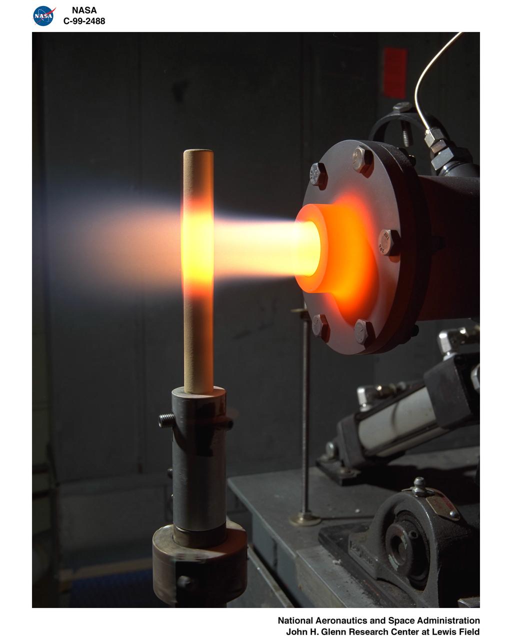
A burner rig heats up a material sample in the Materials and Stresses Building at the National Aeronautics and Space Administration (NASA) Lewis Research Center. Materials technology is an important element in the successful development of advanced airbreathing and rocket propulsion systems. Different types of engines operate in different environments so an array of dependable materials is needed. NASA Lewis began investigating the characteristics of different materials shortly after World War II. In 1949 the materials group was expanded into its own division. The Lewis researchers sought to study and test materials in environments that simulate the environment in which they would operate. The Materials and Stresses Building, built in 1949, contained a number of laboratories to analyze the materials. They are subjected to high temperatures, high stresses, corrosion, irradiation, and hot gasses. The Physics of Solids Laboratory included a cyclotron, cloud chamber, helium cryostat, and metallurgy cave. The Metallographic Laboratory possessed six x-ray diffraction machines, two metalloscopes, and other equipment. The Furnace Room had two large induction machines, a 4500⁰ F graphite furnace, and heat treating equipment. The Powder Laboratory included 60-ton and 3000-ton presses. The Stresses Laboratory included stress rupture machines, fatigue machines, and tensile strength machines.
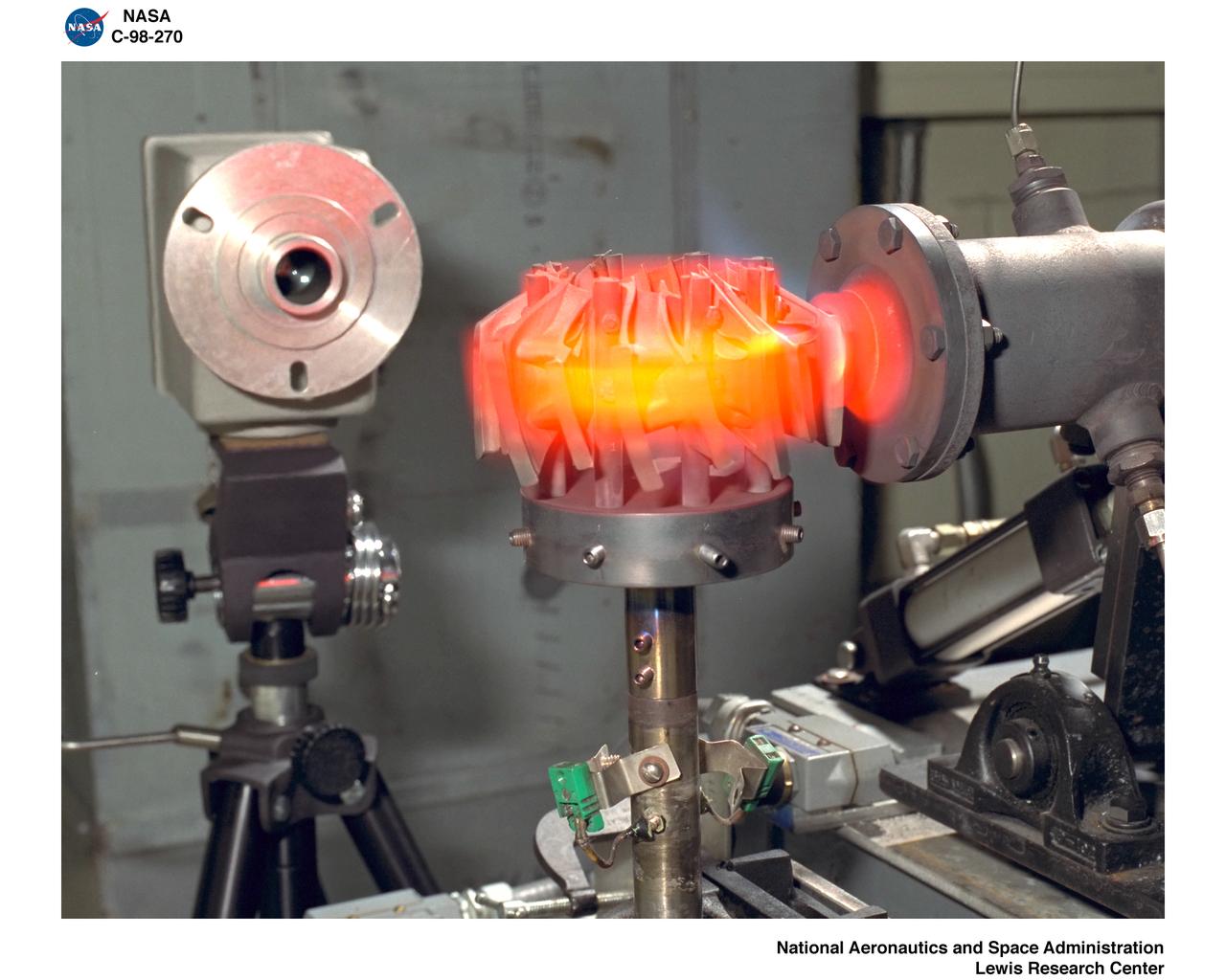
BURNER RIG 126 CELL VANES 1 HOT 1 COLD - BURNER RIG 121 CELL BLADES 1 HOT 1 COLD
Burner Rig Laboratory

MICRO MACHINING STAINLESS STEEL BURNER

FAST QUIET EXPERIMENT TEST ON THE MACH 3 BURNER RIG

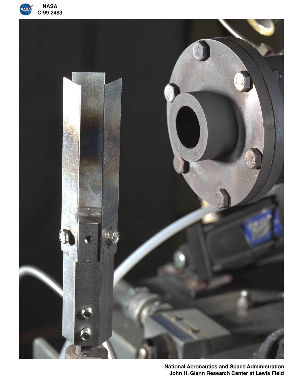
BURNER RIG TESTS IN BOTH HEATING AND COOLING POSITIONS - TITANIUM ALUMINIDE ALLOY TEST - HOT
BURNER RIG TESTS IN BOTH HEATING AND COOLING POSITIONS - THERMAL BARRIER COATED SUPER ALLOY - HOT
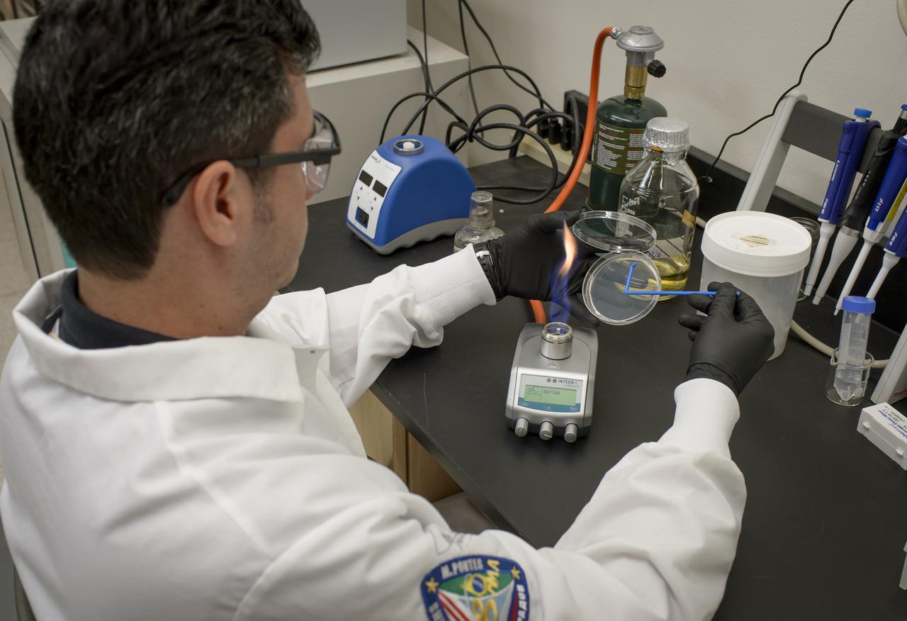
EuCROPIS EVT-2 Power Cell in N-239 Lab, Ivan Paulino-Lima with Petri dish and burner
BURNER RIG TESTS IN BOTH HEATING AND COOLING POSITIONS - RADOME CERAMIC MISSILE - EROSION RIG - THERMAL BARRIER COATED SAMPLE
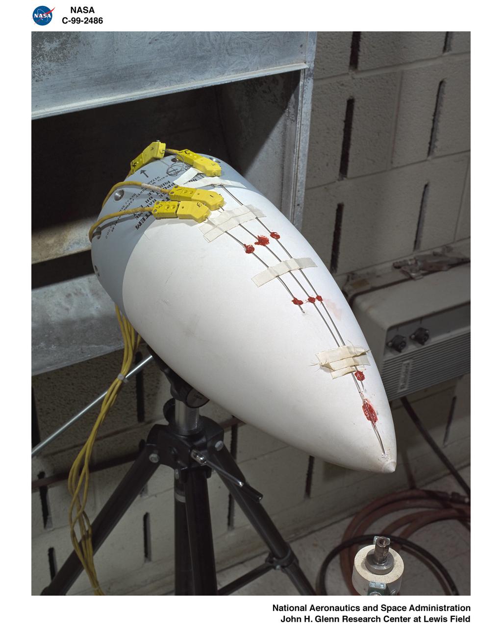
BURNER RIG TESTS IN BOTH HEATING AND COOLING POSITIONS - CERAMIC MISSILE RADOME TEST
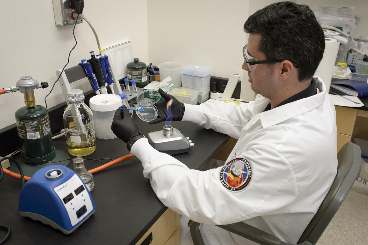
EuCROPIS EVT-2 Power Cell in N-239 Lab, Ivan Paulino-Lima with Petri dish and burner
NASA Glenn engineer Christopher Mroczka inspects the gas-jet burner within the Advanced Combustion via Microgravity Experiments, ACME insert for the Combustion Integrated Rack, CIR. The apparatus allows researchers to conduct experiments with flames of gaseous fuels on the International Space Station, ISS
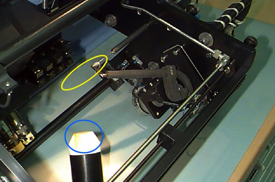
Interior of the Equipment Module for the Laminar Soot Processes (LSP-2) experiment that fly in the STS-107 Research 1 mission in 2002 (LSP-1 flew on Microgravity Sciences Lab-1 mission in 1997). The principal investigator is Dr. Gerard Faeth of the University of Michigan. LSP uses a small jet burner (yellow ellipse), similar to a classroom butane lighter, that produces flames up to 60 mm (2.3 in) long. Measurements include color TV cameras and a radiometer or heat sensor (blue circle), and laser images whose darkness indicates the quantity of soot produced in the flame. Glenn Research in Cleveland, OH, manages the project.
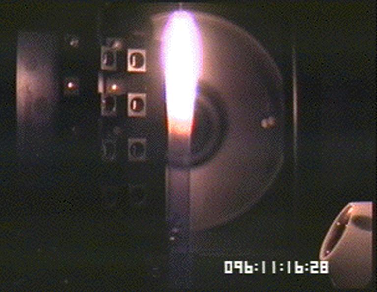
The Laminar Soot Processes (LSP) experiment under way during the Microgravity Sciences Lab-1 mission in 1997. LSP-2 will fly in the STS-107 Research 1 mission in 2001. The principal investigator is Dr. Gerard Faeth of the University of Michigan. LSP uses a small jet burner, similar to a classroom butane lighter, that produces flames up to 60 mm (2.3 in) long. Measurements include color TV cameras and a temperature sensor, and laser images whose darkness indicates the quantity of soot produced in the flame. Glenn Research in Cleveland, OH, manages the project.
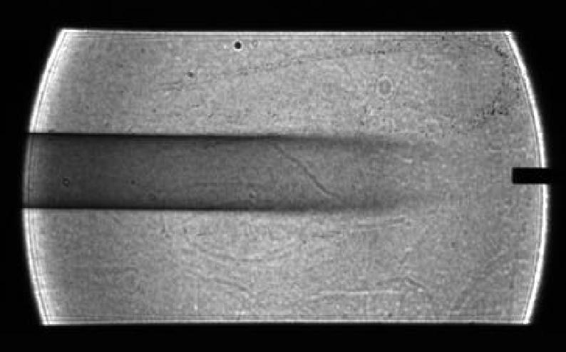
Image of soot (smoke) plume made for the Laminar Soot Processes (LSP) experiment during the Microgravity Sciences Lab-1 mission in 1997. LSP-2 will fly in the STS-107 Research 1 mission in 2002. The principal investigator is Dr. Gerard Faeth of the University of Michigan. LSP uses a small jet burner, similar to a classroom butane lighter, that produces flames up to 60 mm (2.3 in) long. Measurements include color TV cameras and a temperature sensor, and laser images whose darkness indicates the quantity of soot produced in the flame. Glenn Research in Cleveland, OH, manages the project.
A General Electric TG-180 turbojet installed in the Altitude Wind Tunnel at the National Advisory Committee for Aeronautics (NACA) Lewis Flight Propulsion Laboratory. In 1943 the military asked General Electric to develop an axial-flow jet engine which became the TG-180. The military understood that the TG-180 would not be ready during World War II but recognized the axial-flow compressor’s long-term potential. Although the engine was bench tested in April 1944, it was not flight tested until February 1946. The TG-180 was brought to the Altitude Wind Tunnel in 1945 for a series of investigations. The studies, which continued intermittently into 1948, analyzed an array of performance issues. NACA modifications steadily improved the TG-180’s performance, including the first successful use of an afterburner. The Lewis researchers studied a 29-inch diameter afterburner over a range of altitude conditions using several different types of flameholders and fuel systems. Lewis researchers concluded that a three-stage flameholder with its largest stage upstream was the best burner configuration. Although the TG-180 (also known as the J35) was not the breakthrough engine that the military had hoped for, it did power the Douglas D-558-I Skystreak to a world speed record on August 20, 1947. The engines were also used on the Republic F-84 Thunderjet and the Northrup F-89 Scorpion.
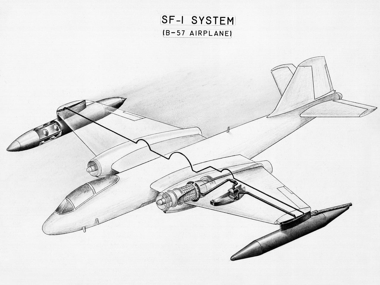
This diagram shows a hydrogen fuel system designed by researchers at the National Advisory Committee for Aeronautics (NACA) Lewis Flight Propulsion Laboratory and installed on a Martin B-57B Canberra aircraft. Lewis researchers accelerated their studies of high energy propellants in the early 1950s. In late 1954, Lewis researchers studied the combustion characteristics of gaseous hydrogen in a turbojet combustor. It was found that the hydrogen provided a very high efficiency. Almost immediately thereafter, Associate Director Abe Silverstein became focused on the possibilities of hydrogen for aircraft propulsion. That fall, Silverstein secured a contract to work with the air force to examine the practicality of liquid hydrogen aircraft. A B-57B Canberra was obtained by the air force especially for this project, referred to as Project Bee. The aircraft was powered by two Wright J65 engines, one of which was modified so that it could be operated using either traditional or liquid hydrogen propellants. The engine and its liquid hydrogen fuel system were tested extensively in the Altitude Wind Tunnel and the Four Burner Area test cells in 1955 and 1956. A B-57B flight program was planned to test the system on an actual aircraft. The aircraft would take off using jet fuel, switch to liquid hydrogen while over Lake Erie, then after burning the hydrogen supply switch back to jet fuel for the landing. The third test flight, in February 1957, was a success, and the ensuing B-57B flights remain the only demonstration of hydrogen-powered aircraft.
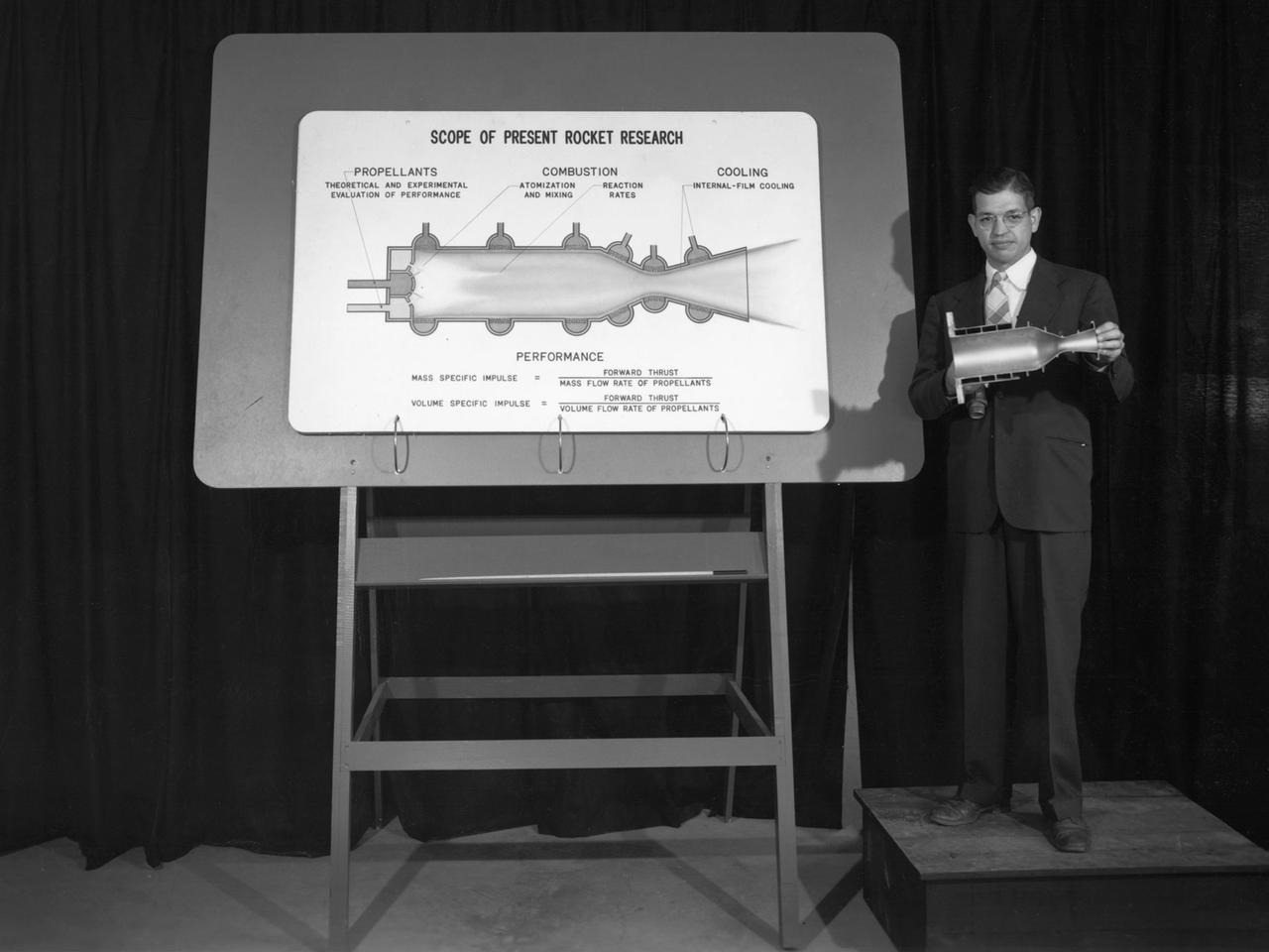
Researcher John Sloop briefs visitors on his latest rocket engine research during the 1947 Inspection at the National Advisory Committee for Aeronautics (NACA) Lewis Flight Propulsion Laboratory. The NACA had been hosting annual Aircraft Engineering Conferences, better known as Inspections, since 1926. Individuals from the manufacturing industry, military, and university settings were invited to tour the NACA laboratories. There were a series of stops on the tour, mostly at test facilities, where researchers would brief the group on the latest efforts in their particular field. The Inspections grew in size and scope over the years and by the mid-1940s required multiple days. The three-day 1947 Inspection was the first time the event was held at NACA Lewis. Over 800 scientists, industrialists, and military leaders attended the three-day event. Talks were given at the Altitude Wind Tunnel, Four Burner Area, Engine Research Building, and other facilities. An array of topics were discussed, including full-scale engine testing, ramjets, axial-flow compressors, turbojets, fuels, icing, and materials. The NACA Lewis staff and their families were able to view the same presentations after the Inspection was over. Sloop, a researcher in the Fuels and Thermodynamics Division, briefed visitors on NACA Lewis’ early research in rocket engine propellants, combustion, and cooling. This early NACA Lewis work led to the development of liquid hydrogen as a viable propellant in the late 1950s.