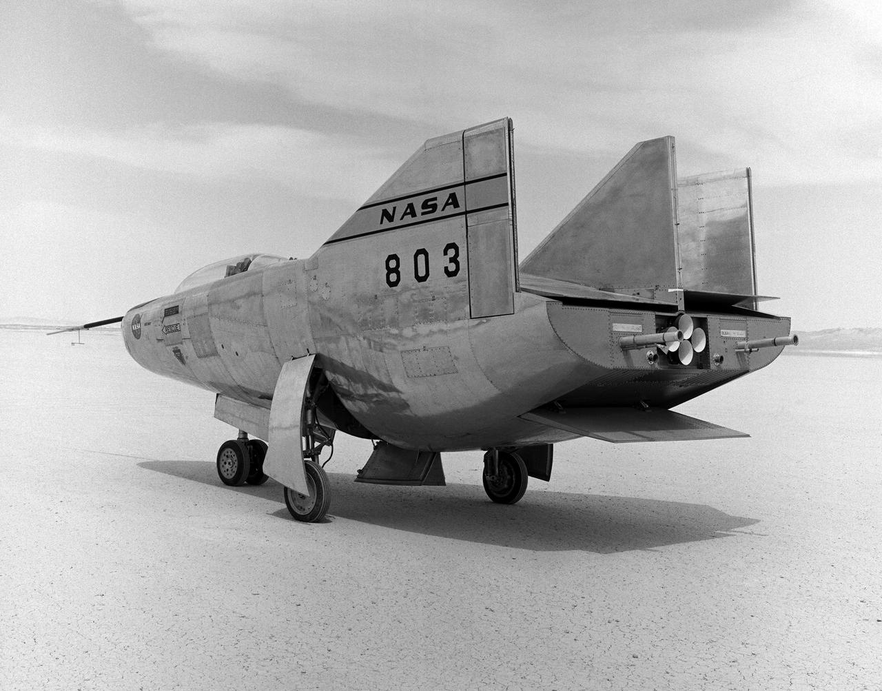
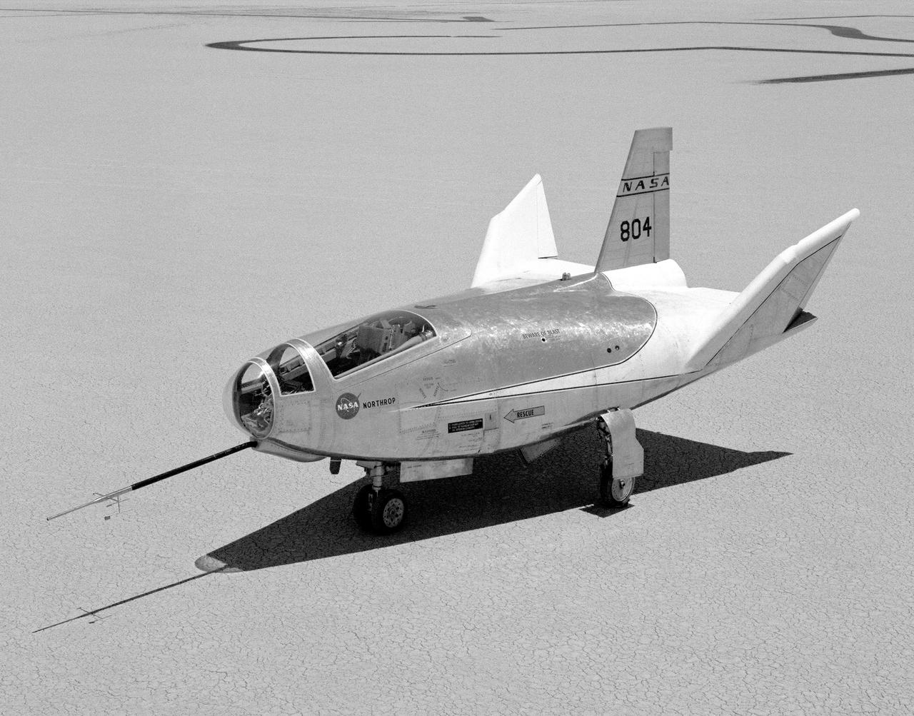
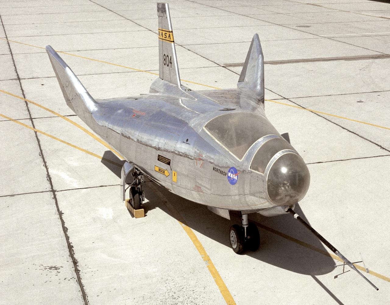
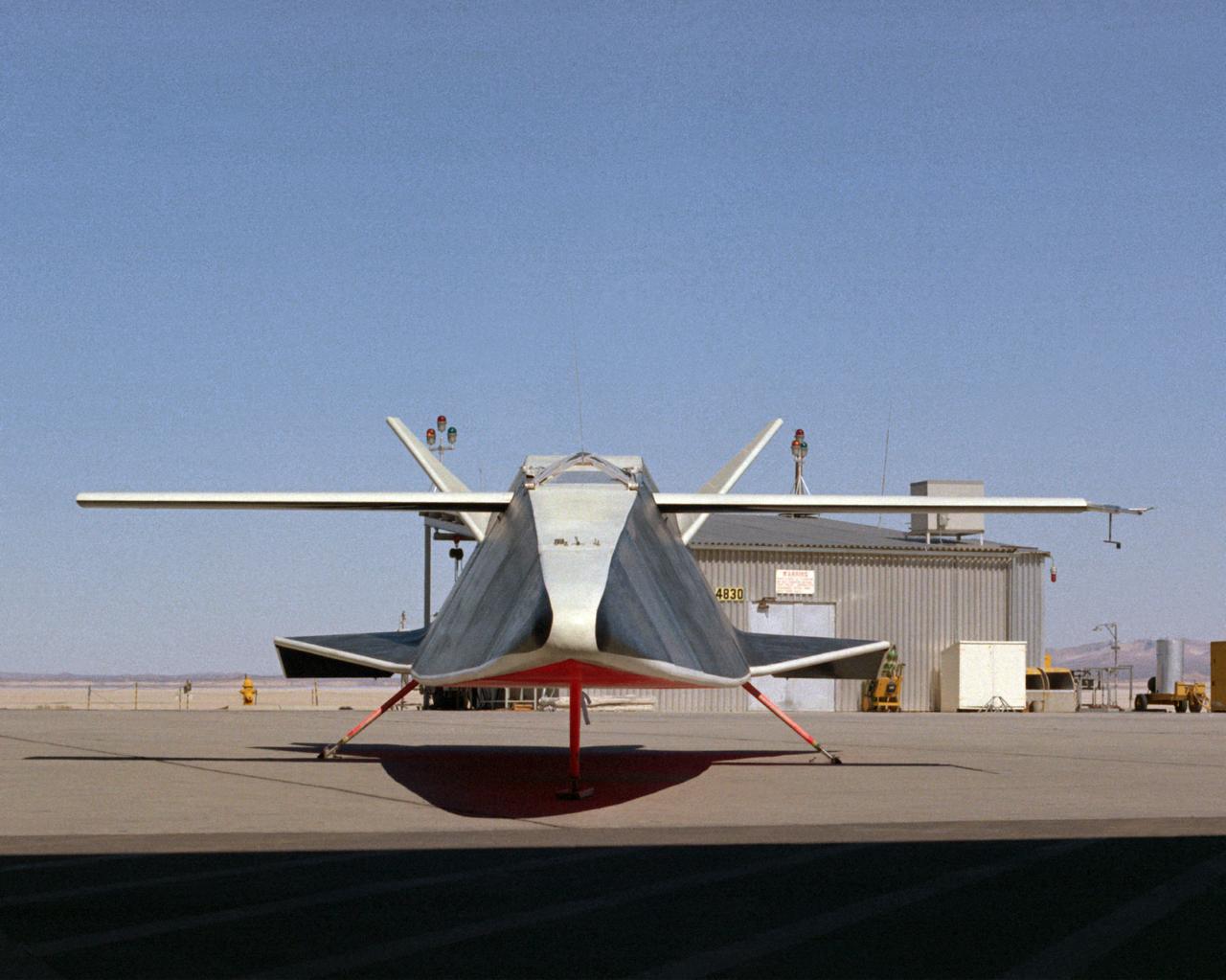
The M2-F3 Lifting Body is seen here on the lakebed next to the NASA Flight Research Center (later the Dryden Flight Research Center), Edwards, California. Redesigned and rebuilt from the M2-F2, the M2-F3 featured as its most visible change a center fin for greater stability. While the M2-F3 was still demanding to fly, the center fin eliminated the high risk of pilot induced oscillation (PIO) that was characteristic of the M2-F2.
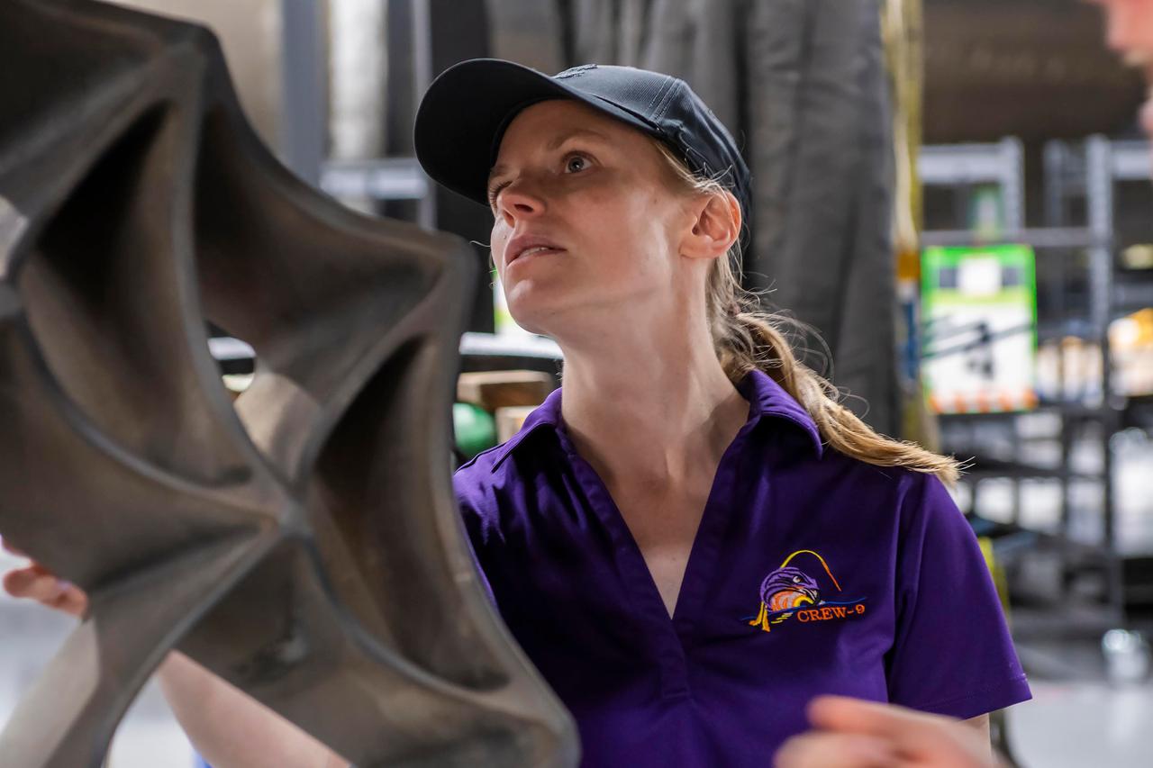
jsc2024e050142 (May 13, 2024) --- NASA’s SpaceX Crew-9 Commander Zena Cardman checks out a grid fin on a Falcon 9 first-stage booster at SpaceX’s HangarX facility at NASA's Kennedy Space Center in Florida. Credit: SpaceX
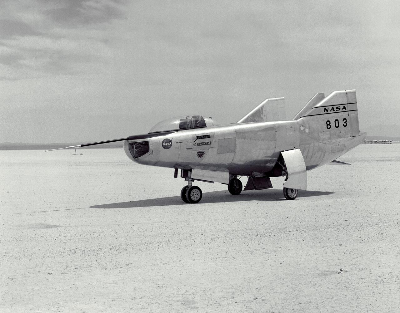
The M2-F3 Lifting Body is seen here on the lakebed at the NASA Flight Research Center (FRC--later the Dryden Flight Research Center), Edwards, California. After a three-year-long redesign and rebuilding effort, the M2-F3 was ready to fly. The May 1967 crash of the M2-F2 had damaged both the external skin and the internal structure of the lifting body. At first, it seemed that the vehicle had been irreparably damaged, but the original manufacturer, Northrop, did the repair work and returned the redesigned M2-F3 with a center fin for stability to the FRC.
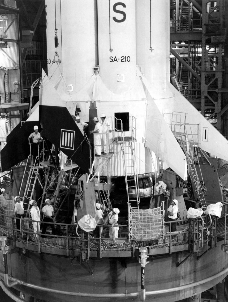
KENNEDY SPACE CENTER, FLA. -- The replacement of fins on the Apollo Soyuz Test Project S1B launch vehicle continued at KSC today. The decision to replace all of the fins was made when small hairline stress corrosion cracks were discovered in holddown fittings. Replacement of the fins is not expected to delay move of the launch vehicle to the launch pad on March 24. ASTP, the joint U.S._USSR space mission is scheduled for mid-July.
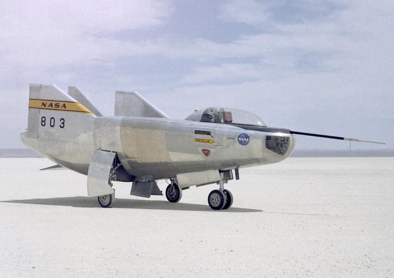
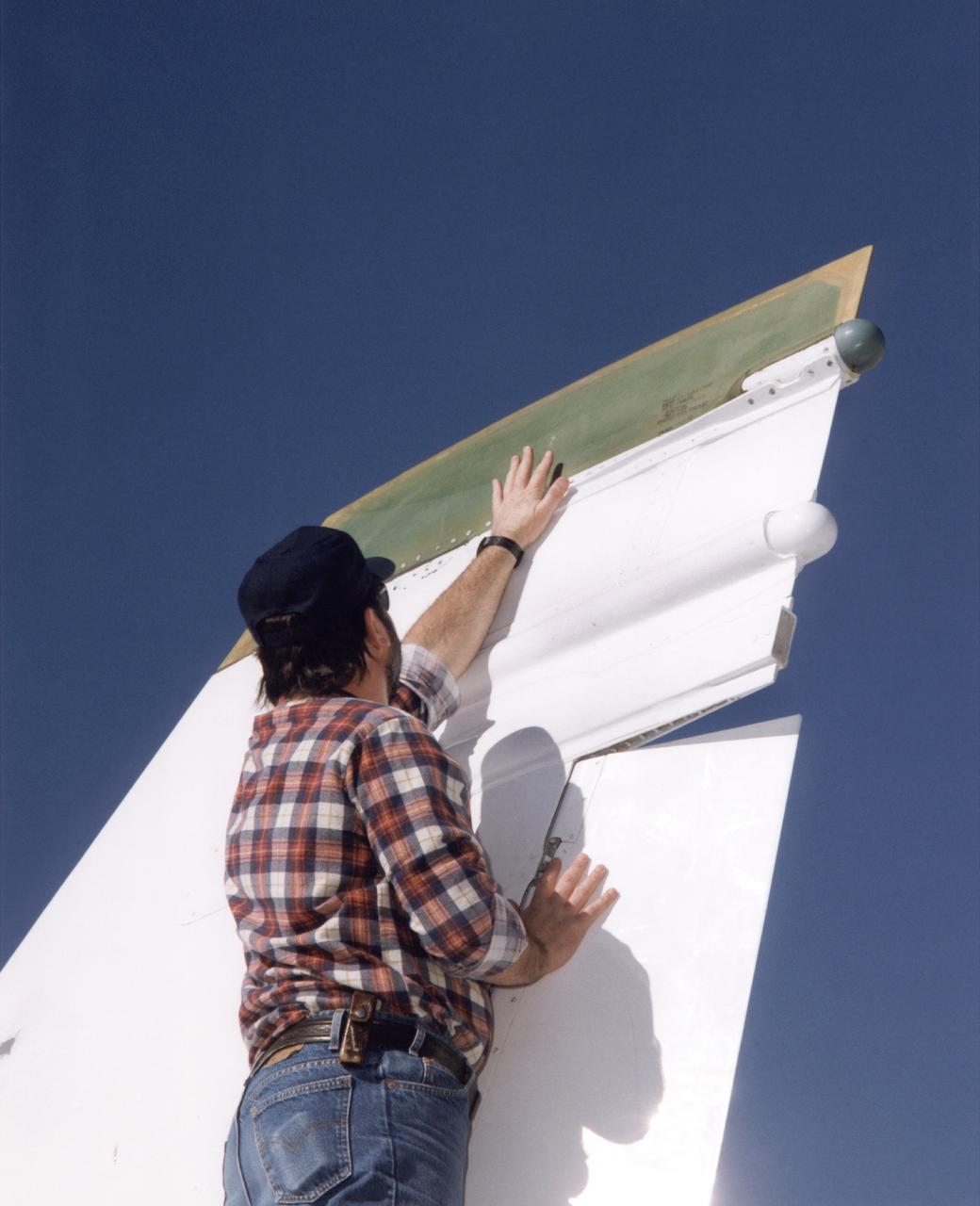
The HL-10 Lifting Body is seen here parked on Rogers Dry Lake, the unique location where it landed after research flights. This 1968 photo shows the vehicle after the fins were modified to remove instabilities encountered on the first flight. It involved a change to the shape of the leading edge of the fins to eliminate flow separation. It required extensive wind-tunnel testing at Langley Research Center, Hampton, Va. NASA Flight Research Center (FRC) engineer Bob Kempel than plotted thousands of data points by hand to come up with the modification, which involved a fiberglass glove backed with a metal structure on each fin's leading edge. This transformed the vehicle from a craft that was difficult to control into the best handling of the original group of lifting bodies at the FRC.
The M2-F3 Lifting Body is seen here on the lakebed next to the NASA Flight Research Center (FRC--later Dryden Flight Research Center), Edwards, California. The May 1967 crash of the M2-F2 had torn off the left fin and landing gear. It had also damaged the external skin and internal structure. Flight Research Center engineers worked with Ames Research Center and the Air Force in redesigning the vehicle with a center fin to provide greater stability. Then Northrop Corporation cooperated with the FRC in rebuilding the vehicle. The entire process took three years.
Bob Cummings, a technician at NASA's Dryden Flight Research Center, Edwards, California, checks out a new "Smart Skin" antenna mounted on the tip of the right vertical fin of Dryden's F/A-18 Systems Research Aircraft. Flight tests of the antenna system demonstrated a five-fold increase in voice communications range and a substantial improvement in the pattern of radiation and quality of transmission compared to the standard dorsal blade antenna on the aircraft. The Smart Skin antenna system was electrically as well as physically connected to the airframe, making the aircraft skin operate as an antenna along with the antenna itself. The concept was developed by TRW Avionics Systems Division and integrated into the F/A-18's vertical fin by Northrop-Grumman Corporation.
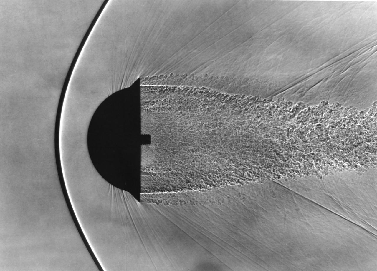
Shadowgraph of Finned Hemispherical model in free-flight show shock waves produced by blunt bodies (H. Julian Allen blunt nose theory) (Used in NASA/AMES publication 'Adventures in Research' A history of Ames Research Center 1940 - 1965 by Edwin P. Hartman - SP-4302)
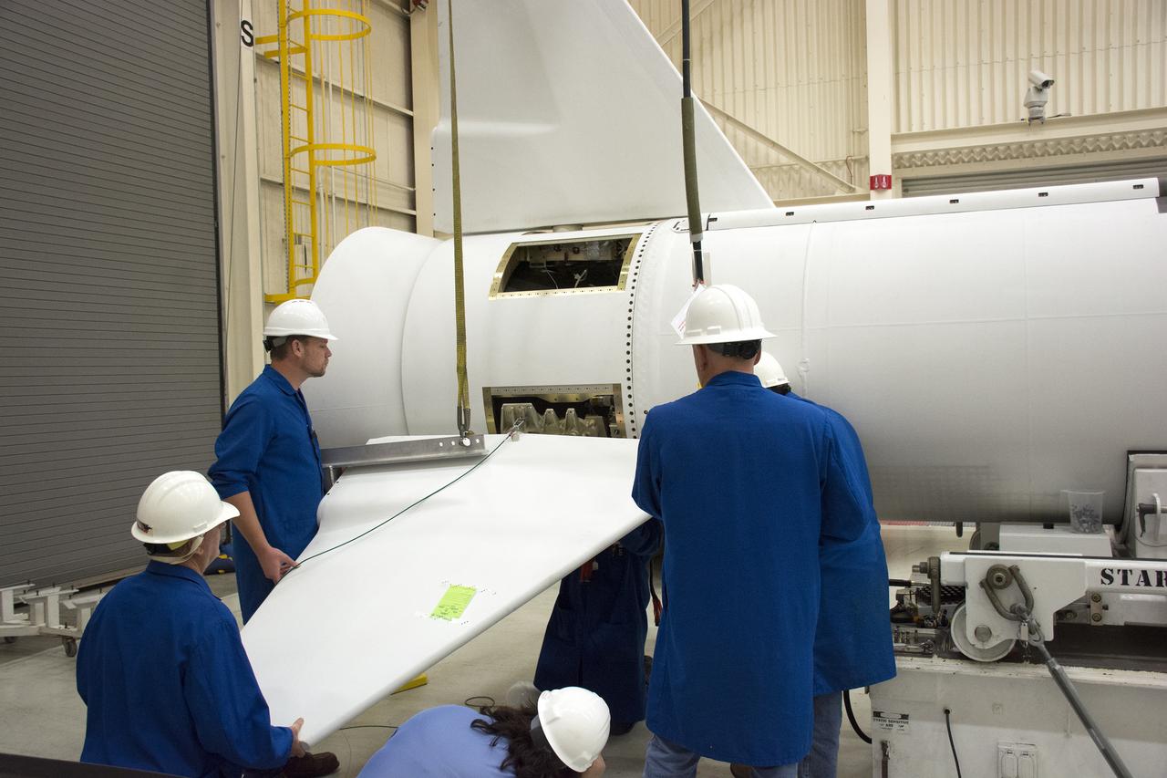
Technicians prepare to install one of the fins on the Orbital ATK Pegasus XL rocket inside Building 1555 at Vandenberg Air Force Base in California. The fins will provide aerodynamic stability during flight. The rocket is being prepared at Vandenberg, and then will be transported to NASA’s Kennedy Space Center in Florida attached to the Orbital ATK L-1011 carrier aircraft with NASA’s Cyclone Global Navigation Satellite System (CYGNSS) in its payload fairing. CYGNSS will launch on the Pegasus XL rocket from the Skid Strip at Cape Canaveral Air Force Station. CYGNSS will make frequent and accurate measurements of ocean surface winds throughout the life cycle of tropical storms and hurricanes. The data that CYGNSS provides will enable scientists to probe key air-sea interaction processes that take place near the core of storms, which are rapidly changing and play a critical role in the beginning and intensification of hurricanes.
Technicians prepare to install one of the fins on the Orbital ATK Pegasus XL rocket inside Building 1555 at Vandenberg Air Force Base in California. The fins will provide aerodynamic stability during flight. The rocket is being prepared at Vandenberg, and then will be transported to NASA’s Kennedy Space Center in Florida attached to the Orbital ATK L-1011 carrier aircraft with NASA’s Cyclone Global Navigation Satellite System (CYGNSS) in its payload fairing. CYGNSS will launch on the Pegasus XL rocket from the Skid Strip at Cape Canaveral Air Force Station. CYGNSS will make frequent and accurate measurements of ocean surface winds throughout the life cycle of tropical storms and hurricanes. The data that CYGNSS provides will enable scientists to probe key air-sea interaction processes that take place near the core of storms, which are rapidly changing and play a critical role in the beginning and intensification of hurricanes.
Technicians prepare to install one of the fins on the Orbital ATK Pegasus XL rocket inside Building 1555 at Vandenberg Air Force Base in California. The fins will provide aerodynamic stability during flight. The rocket is being prepared at Vandenberg, and then will be transported to NASA’s Kennedy Space Center in Florida, attached to the Orbital ATK L-1011 carrier aircraft with NASA’s Cyclone Global Navigation Satellite System (CYGNSS) in its payload fairing. CYGNSS will launch on the Pegasus XL rocket from the Skid Strip at Cape Canaveral Air Force Station. CYGNSS will make frequent and accurate measurements of ocean surface winds throughout the life cycle of tropical storms and hurricanes. The data that CYGNSS provides will enable scientists to probe key air-sea interaction processes that take place near the core of storms, which are rapidly changing and play a critical role in the beginning and intensification of hurricanes.
Technicians prepare one of the fins for installation on the Orbital ATK Pegasus XL rocket inside Building 1555 at Vandenberg Air Force Base in California. The fins will provide aerodynamic stability during flight. The rocket is being prepared at Vandenberg, and then will be transported to NASA’s Kennedy Space Center in Florida, attached to the Orbital ATK L-1011 carrier aircraft with NASA’s Cyclone Global Navigation Satellite System (CYGNSS) in its payload fairing. CYGNSS will launch on the Pegasus XL rocket from the Skid Strip at Cape Canaveral Air Force Station. CYGNSS will make frequent and accurate measurements of ocean surface winds throughout the life cycle of tropical storms and hurricanes. The data that CYGNSS provides will enable scientists to probe key air-sea interaction processes that take place near the core of storms, which are rapidly changing and play a critical role in the beginning and intensification of hurricanes.
Technicians prepare to install one of the fins on the Orbital ATK Pegasus XL rocket inside Building 1555 at Vandenberg Air Force Base in California. The fins will provide aerodynamic stability during flight. The rocket is being prepared at Vandenberg, and then will be transported to NASA’s Kennedy Space Center in Florida attached to the Orbital ATK L-1011 carrier aircraft with NASA’s Cyclone Global Navigation Satellite System (CYGNSS) in its payload fairing. CYGNSS will launch on the Pegasus XL rocket from the Skid Strip at Cape Canaveral Air Force Station. CYGNSS will make frequent and accurate measurements of ocean surface winds throughout the life cycle of tropical storms and hurricanes. The data that CYGNSS provides will enable scientists to probe key air-sea interaction processes that take place near the core of storms, which are rapidly changing and play a critical role in the beginning and intensification of hurricanes.
The HL-10, seen here parked on the ramp at NASA's Flight Research Center in 1966, had a radically different shape from that of the M2-F2/F3. While the M2s were flat on top and had rounded undersides (giving them a bathtub shape), the HL-10 had a flat lower surface and a rounded top. Both shapes provided lift without wings, however. This photo was taken before the HL-10's fins were modified.
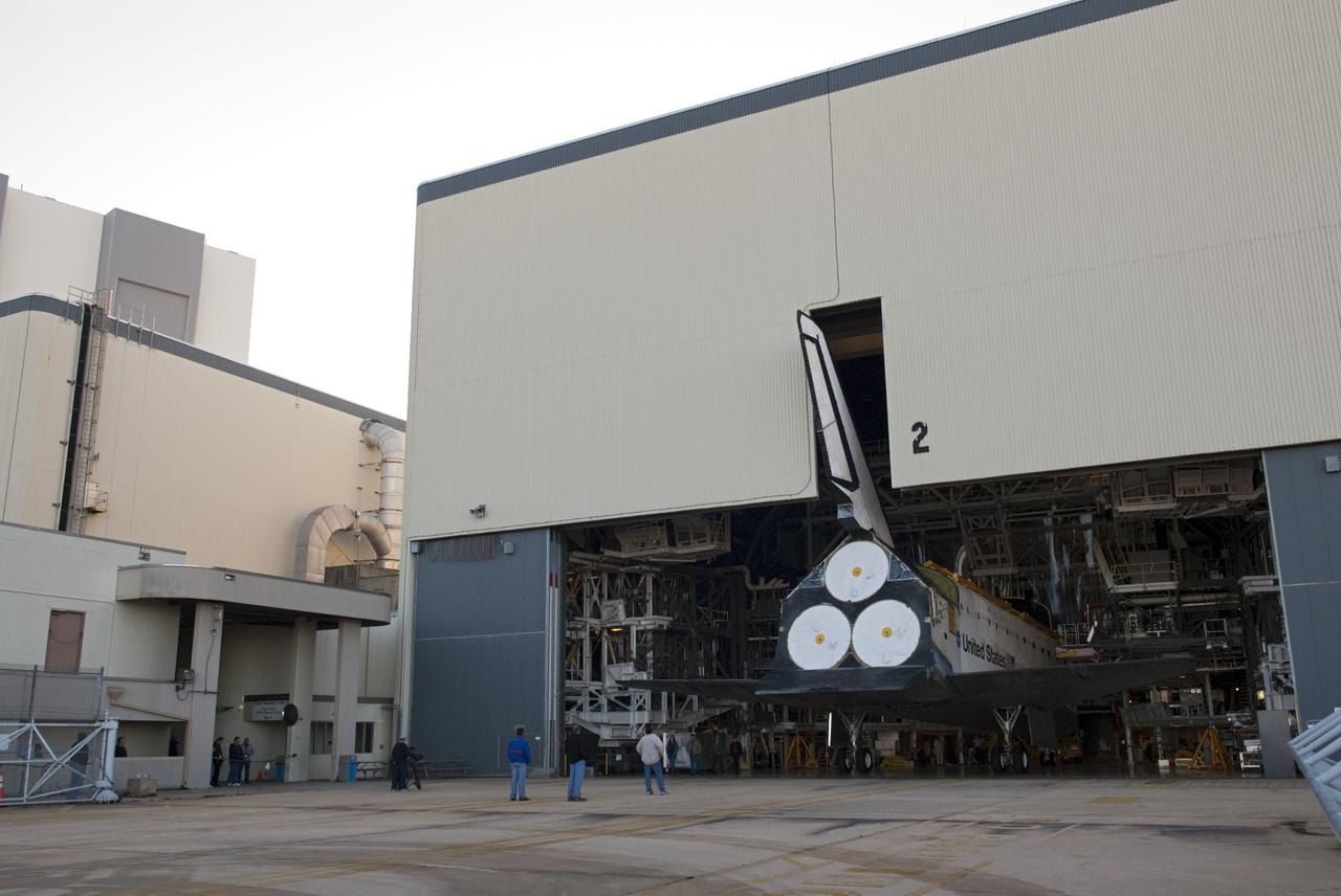
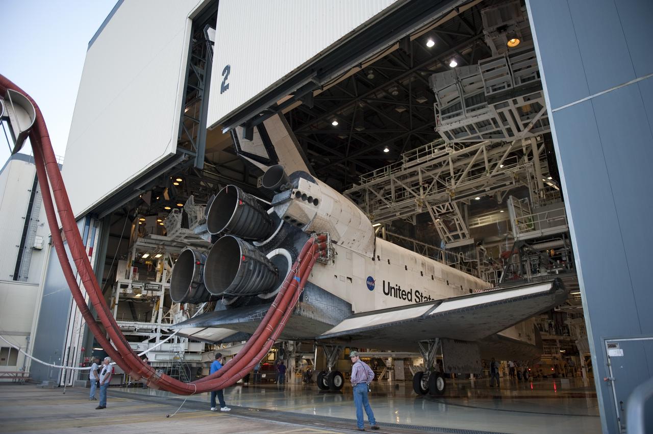
CAPE CANAVERAL, Fla. -- The tail fin of space shuttle Atlantis emerges through the open door of Orbiter Processing Facility-2 on its move to the Vehicle Assembly Building (VAB) at NASA's Kennedy Space Center in Florida. Atlantis will be stored temporarily in the VAB while transition and retirement processing resumes on shuttle Endeavour in the processing hangar. Endeavour is being prepared for public display at the California Science Center in Los Angeles. A groundbreaking was held Jan. 18 for Atlantis' future home -- a 65,000-square-foot exhibit in Shuttle Plaza at the Kennedy Space Center Visitor Complex. For additional information, visit http://www.nasa.gov/shuttle. Photo credit: NASA/Charisse Nahser
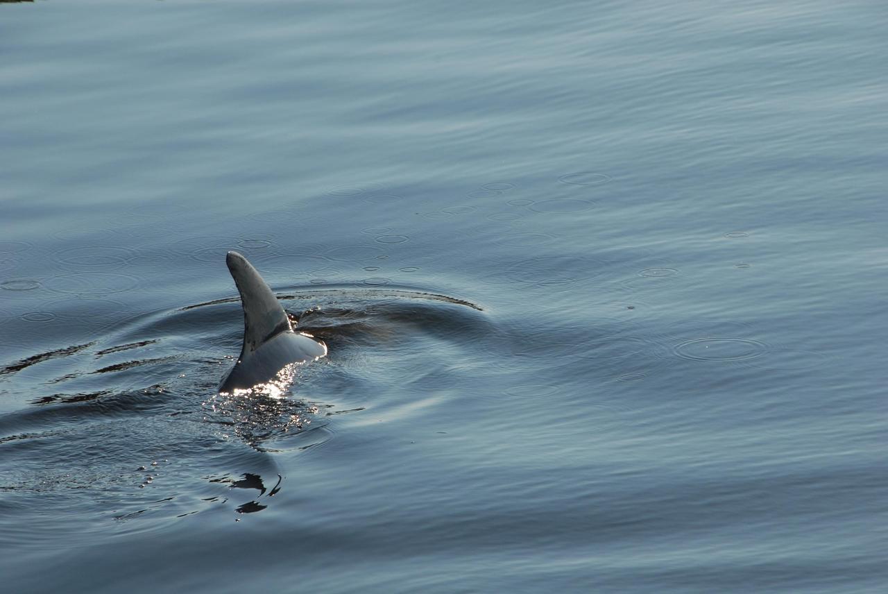
KENNEDY SPACE CENTER, FLA. -- A dolphin's dorsal fin cuts through the water in the Launch Complex 39 Area turn basin at NASA's Kennedy Space Center. The turn basin was carved out of the Banana River when Kennedy Space Center was built. Dolphins frequent bays and coastlines, usually in depths under 20 meters. While some pods take up permanent residence and establish home waters, others are migratory and swim considerable distances from coast to coast. Dolphins are a frequent sight in the rivers around Kennedy, which shares a boundary with the Merritt Island Wildlife Nature Refuge. Photo credit: NASA/George Shelton
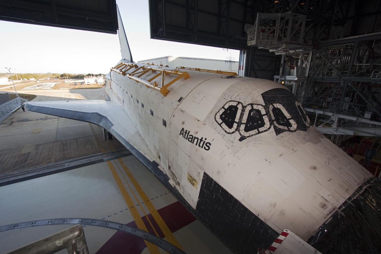
CAPE CANAVERAL, Fla. -- The tail fin of space shuttle Atlantis emerges through the open door of Orbiter Processing Facility-2 on its move to the Vehicle Assembly Building (VAB) at NASA's Kennedy Space Center in Florida. Atlantis will be stored temporarily in the VAB while transition and retirement processing resumes on shuttle Endeavour in the processing hangar. Endeavour is being prepared for public display at the California Science Center in Los Angeles. A groundbreaking was held Jan. 18 for Atlantis' future home -- a 65,000-square-foot exhibit in Shuttle Plaza at the Kennedy Space Center Visitor Complex. For additional information, visit http://www.nasa.gov/shuttle. Photo credit: NASA/Jim Grossmann
CAPE CANAVERAL, Fla. - Space shuttle Discovery's tail fin clears the hangar door of Orbiter Processing Facility-2 at NASA's Kennedy Space Center in Florida. Discovery touched down on the Shuttle Landing Facility's Runway 15 at 11:57 a.m., bringing an end to its 39th and final spaceflight mission, STS-133. Discovery and its six-member STS-133 crew delivered the Permanent Multipurpose Module, packed with supplies and critical spare parts, as well as Robonaut 2, the dexterous humanoid astronaut helper, to the International Space Station. Inside the processing facility, Discovery will be prepared for future public display. Photo credit: NASA/Kim Shiflett
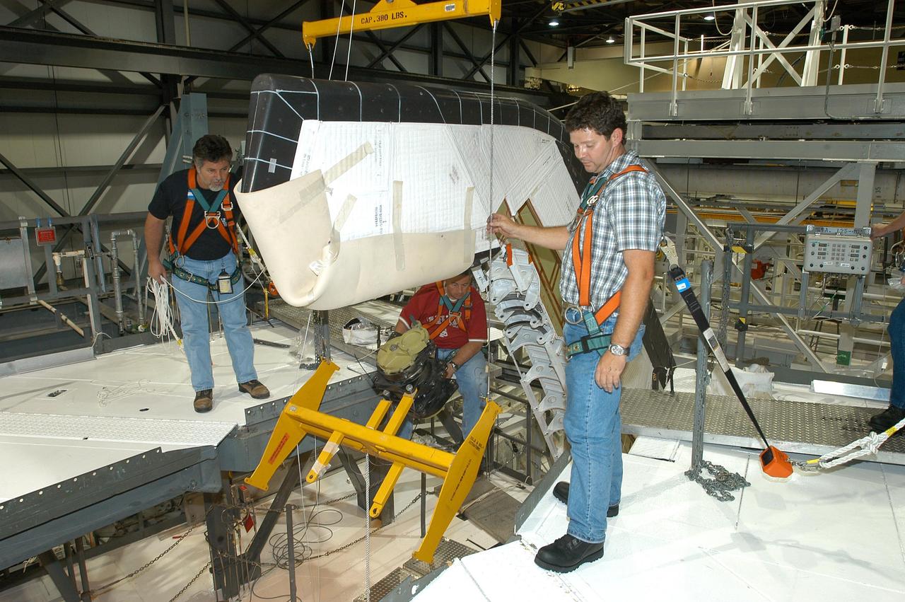
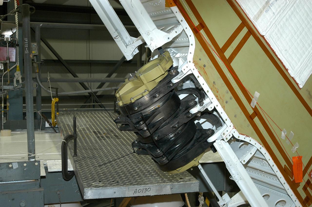
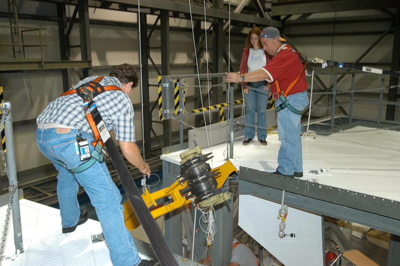
KENNEDY SPACE CENTER, FLA. -- A Rudder Speed Brake Actuator is being removed from the orbiter Atlantis for shipment to the vendor for inspection. An actuator is a motor that moves the tail rudder back and forth to help steer it during landing and brake its speed. The vertical tail consists of a structural fin surface made of aluminum, the Rudder Speed Brake surface, a tip and a lower trailing edge. The rudder splits into two halves to serve as a speed brake. The vertical tail and Rudder Speed Brake are covered with a reusable thermal protection system. Atlantis is undergoing maintenance and inspection in the Orbiter Processing Facility for a future mission.
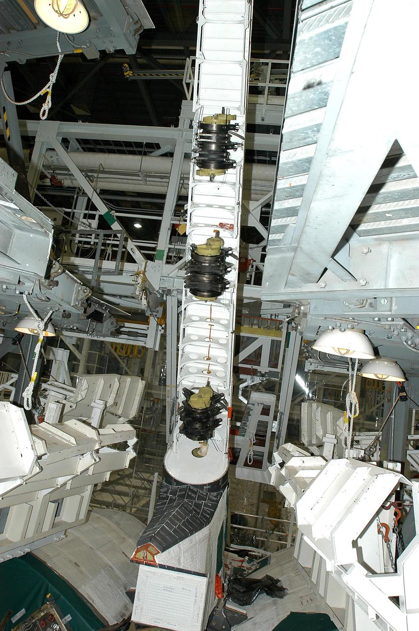
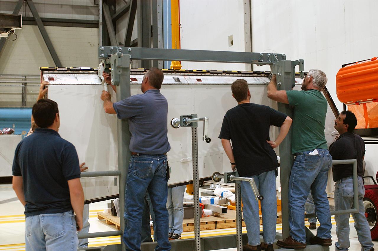
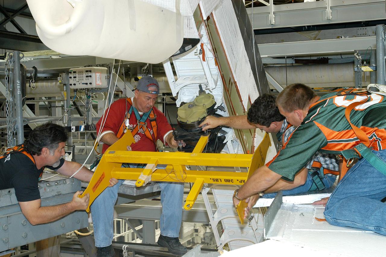
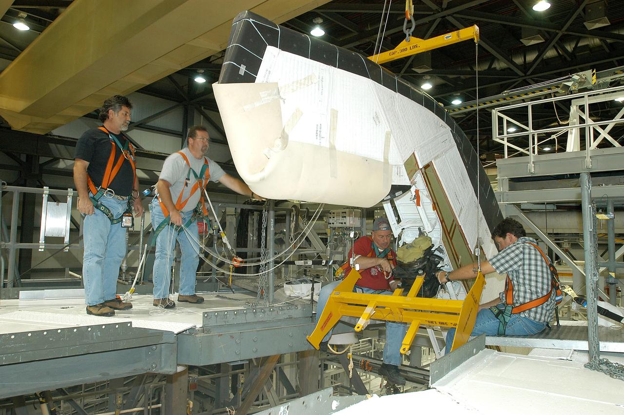
KENNEDY SPACE CENTER, FLA. -- In the Orbiter Processing Facility, a worker (below the upper framework) begins connecting a device to remove the Rudder Speed Brake panel on the vertical tail of orbiter Atlantis. The Rudder Speed Brake is being removed for inspection and maintenance prior to Return to Flight. The vertical tail consists of a structural fin surface made of aluminum, the Rudder Speed Brake surface, a tip and a lower trailing edge. The rudder splits into two halves to serve as a speed brake. The vertical tail and Rudder Speed Brake are covered with a reusable thermal protection system. The Rudder Speed Brake is used to guide and slow the Shuttle as it comes in for a landing.
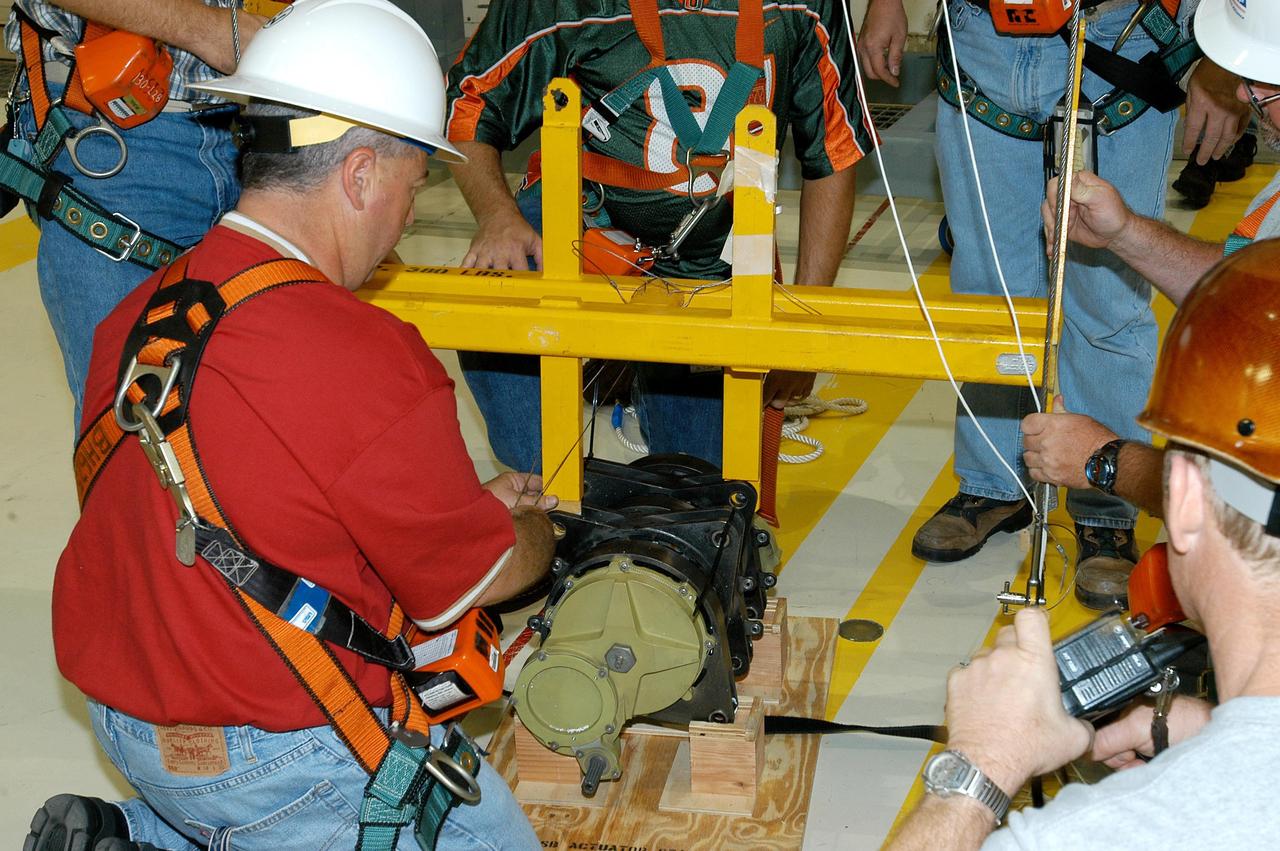
KENNEDY SPACE CENTER, FLA. -- Workers ensure the safe removal of a Rudder Speed Brake Actuator from the orbiter Atlantis. This and three other actuators are being shipped to the vendor for inspection. An actuator is a motor that moves the tail rudder back and forth to help steer it during landing and brake its speed. The vertical tail consists of a structural fin surface made of aluminum, the Rudder Speed Brake surface, a tip and a lower trailing edge. The rudder splits into two halves to serve as a speed brake. The vertical tail and Rudder Speed Brake are covered with a reusable thermal protection system. Atlantis is undergoing maintenance and inspection in the Orbiter Processing Facility for a future mission.
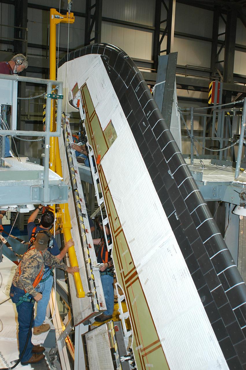
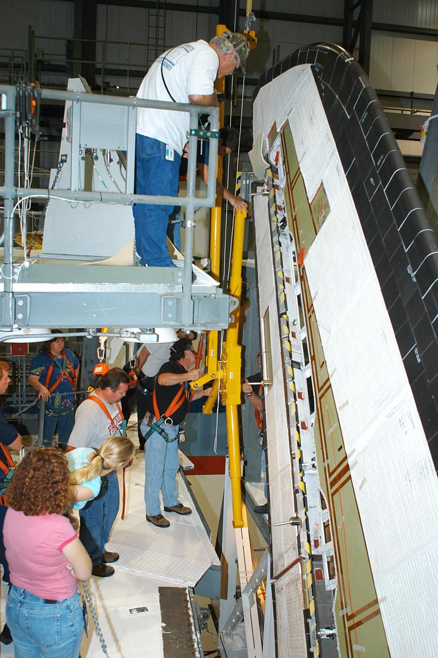
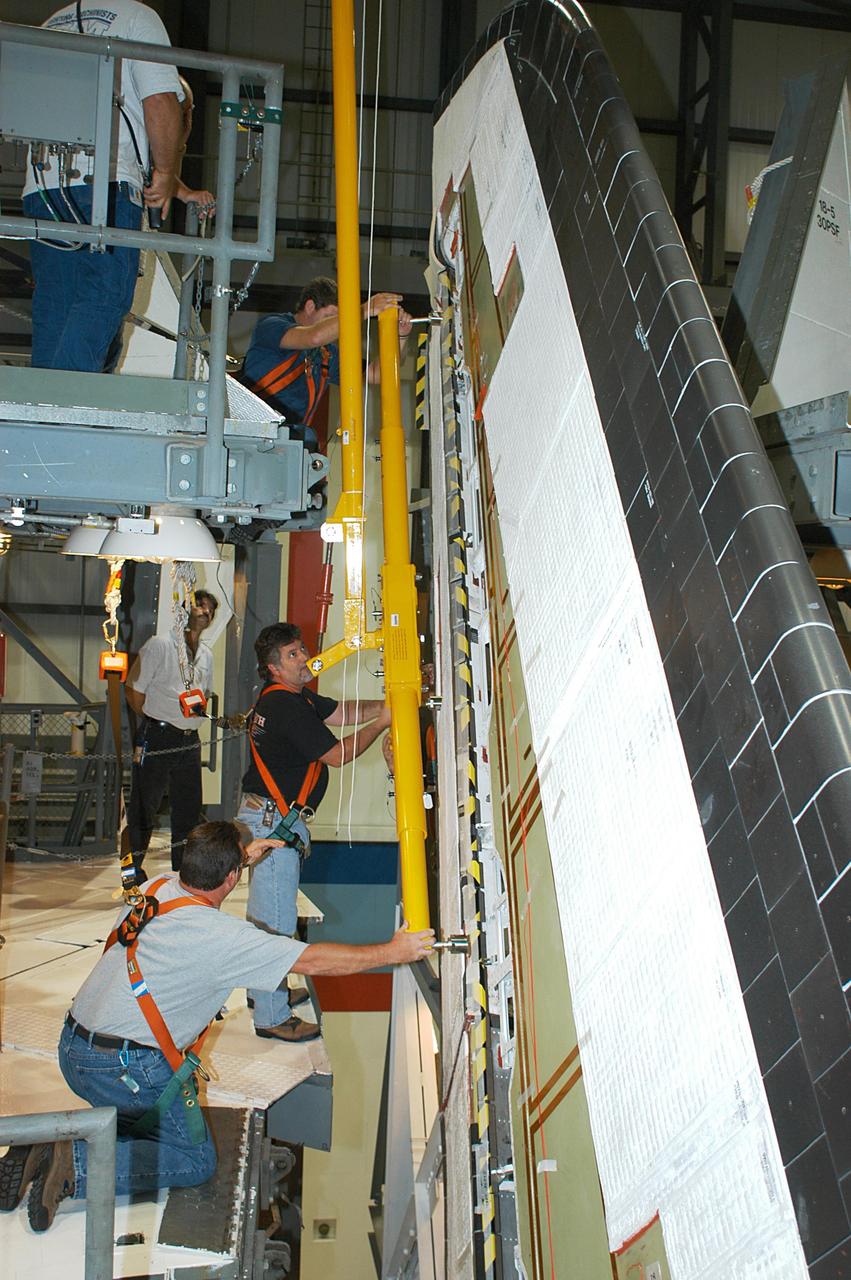
KENNEDY SPACE CENTER, FLA. -- In the Orbiter Processing Facility, workers remove the Rudder Speed Brake panel on the vertical tail of the orbiter Atlantis. The Rudder Speed Brake is being removed for inspection and maintenance prior to Return to Flight. The vertical tail consists of a structural fin surface made of aluminum, the Rudder Speed Brake surface, a tip and a lower trailing edge. The rudder splits into two halves to serve as a speed brake. The vertical tail and Rudder Speed Brake are covered with a reusable thermal protection system. The Rudder Speed Brake is used to guide and slow the Shuttle as it comes in for a landing.
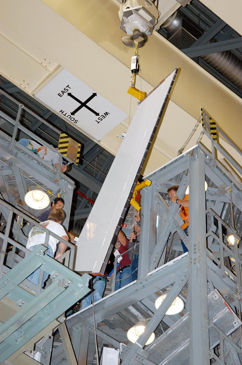
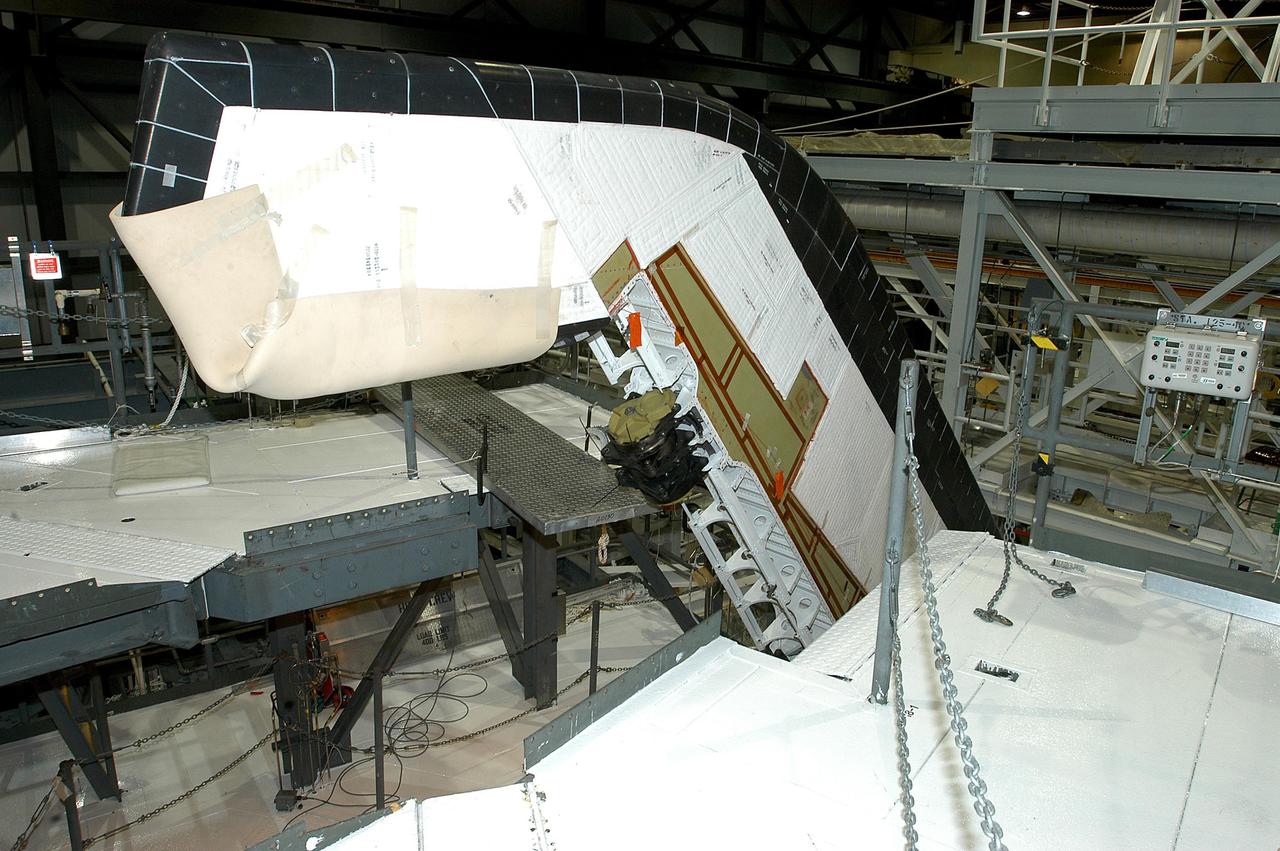
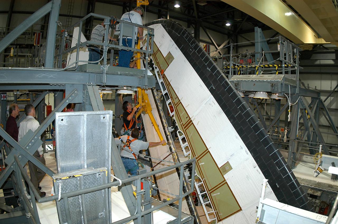
KENNEDY SPACE CENTER, FLA. -- In the Orbiter Processing Facility, workers lower Atlantis’ Rudder Speed Brake panel onto a stand after removing the panel from the vertical tail. The Rudder Speed Brake is being removed for inspection and maintenance prior to Return to Flight. The vertical tail consists of a structural fin surface made of aluminum, the Rudder Speed Brake surface, a tip and a lower trailing edge. The rudder splits into two halves to serve as a speed brake. The vertical tail and Rudder Speed Brake are covered with a reusable thermal protection system. The Rudder Speed Brake is used to guide and slow the Shuttle as it comes in for a landing.
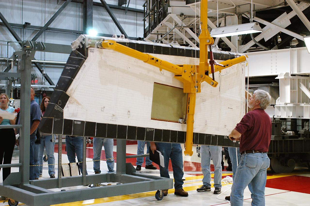
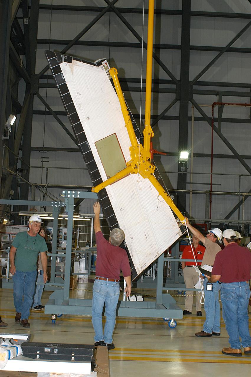
KENNEDY SPACE CENTER, FLA. -- In the Orbiter Processing Facility, the Rudder Speed Brake panel from orbiter Atlantis is lifted clear after being removed. The Rudder Speed Brake is being removed for inspection and maintenance prior to Return to Flight. The vertical tail consists of a structural fin surface made of aluminum, the Rudder Speed Brake surface, a tip and a lower trailing edge. The rudder splits into two halves to serve as a speed brake. The vertical tail and Rudder Speed Brake are covered with a reusable thermal protection system. The Rudder Speed Brake is used to guide and slow the Shuttle as it comes in for a landing.
KENNEDY SPACE CENTER, FLA. -- In the Orbiter Processing Facility, workers attach Atlantis’ Rudder Speed Brake panel to a stand after removing the panel from the vertical tail. The Rudder Speed Brake is being removed for inspection and maintenance prior to Return to Flight. The vertical tail consists of a structural fin surface made of aluminum, the Rudder Speed Brake surface, a tip and a lower trailing edge. The rudder splits into two halves to serve as a speed brake. The vertical tail and Rudder Speed Brake are covered with a reusable thermal protection system. The Rudder Speed Brake is used to guide and slow the Shuttle as it comes in for a landing.
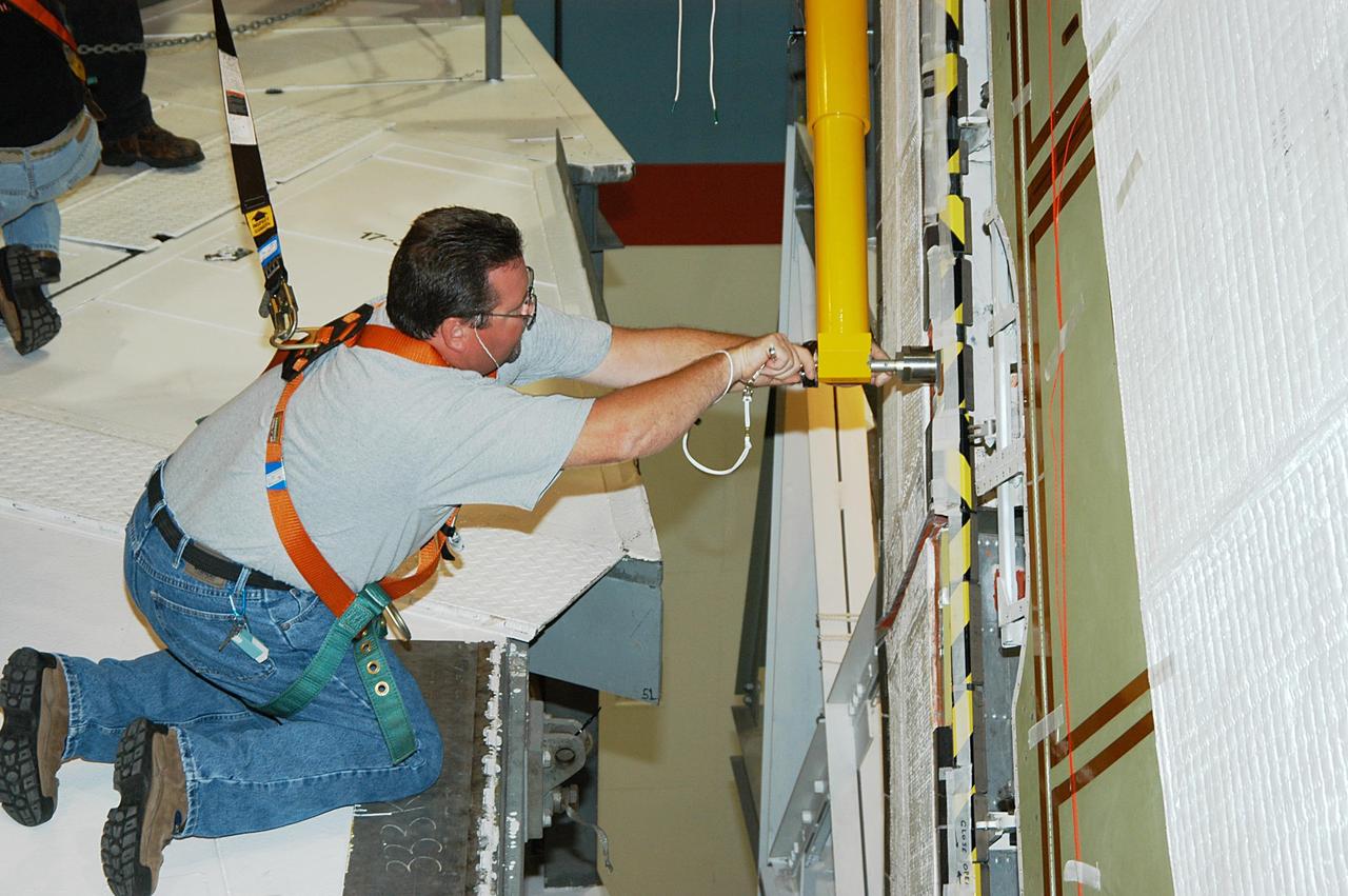
KENNEDY SPACE CENTER, FLA. -- In the Orbiter Processing Facility, a worker tightens a fitting on the device being used to remove the Rudder Speed Brake panel on the vertical tail of the orbiter Atlantis. The Rudder Speed Brake is being removed for inspection and maintenance prior to Return to Flight. The vertical tail consists of a structural fin surface made of aluminum, the Rudder Speed Brake surface, a tip and a lower trailing edge. The rudder splits into two halves to serve as a speed brake. The vertical tail and Rudder Speed Brake are covered with a reusable thermal protection system. The Rudder Speed Brake is used to guide and slow the Shuttle as it comes in for a landing.
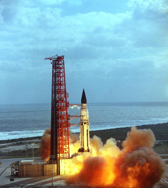
The launch of the SA-5 on January 29, 1964 was the fifth Saturn I launch vehicle. The SA-5 marked a number of firsts in the Marshall Space Flight Center-managed Saturn development program, including the first flight of Saturn I Block II vehicle with eight aerodynamic fins at the bottom of the S-I stage (first stage) for enhanced stability in flight. This also was the first flight of a live S-IV (second or upper) stage with the cluster of six liquid hydrogen-fueled RL-10 engines. the first successful second stage separation, and the first use of the Launch Complex 37.
KENNEDY SPACE CENTER, FLA. -- A Rudder Speed Brake Actuator from the orbiter Atlantis is set on a stand on the floor of the Orbiter Processing Facility. This and three other actuators are being shipped to the vendor for inspection. An actuator is a motor that moves the tail rudder back and forth to help steer it during landing and brake its speed. The vertical tail consists of a structural fin surface made of aluminum, the Rudder Speed Brake surface, a tip and a lower trailing edge. The rudder splits into two halves to serve as a speed brake. The vertical tail and Rudder Speed Brake are covered with a reusable thermal protection system. Atlantis is undergoing maintenance and inspection for a future mission.
KENNEDY SPACE CENTER, FLA. -- Workers attach a crane to one of the Rudder Speed Brake Actuators that are being removed from the orbiter Atlantis for shipment to the vendor for inspection. An actuator is a motor that moves the tail rudder back and forth to help steer it during landing and brake its speed. The vertical tail consists of a structural fin surface made of aluminum, the Rudder Speed Brake surface, a tip and a lower trailing edge. The rudder splits into two halves to serve as a speed brake. The vertical tail and Rudder Speed Brake are covered with a reusable thermal protection system. Atlantis is undergoing maintenance and inspection in the Orbiter Processing Facility for a future mission.

KENNEDY SPACE CENTER, FLA. -- In the Orbiter Processing Facility, workers attach Atlantis’ Rudder Speed Brake panel to a stand after removing the panel from the vertical tail. The Rudder Speed Brake is being removed for inspection and maintenance prior to Return to Flight. The vertical tail consists of a structural fin surface made of aluminum, the Rudder Speed Brake surface, a tip and a lower trailing edge. The rudder splits into two halves to serve as a speed brake. The vertical tail and Rudder Speed Brake are covered with a reusable thermal protection system. The Rudder Speed Brake is used to guide and slow the Shuttle as it comes in for a landing.
KENNEDY SPACE CENTER, FLA. -- A Rudder Speed Brake Actuator is being removed from the orbiter Atlantis for shipment to the vendor for inspection. An actuator is a motor that moves the tail rudder back and forth to help steer it during landing and brake its speed. The vertical tail consists of a structural fin surface made of aluminum, the Rudder Speed Brake surface, a tip and a lower trailing edge. The rudder splits into two halves to serve as a speed brake. The vertical tail and Rudder Speed Brake are covered with a reusable thermal protection system. Atlantis is undergoing maintenance and inspection in the Orbiter Processing Facility for a future mission.
KENNEDY SPACE CENTER, FLA. -- Workers attach a crane to one of the Rudder Speed Brake Actuators that are being removed from the orbiter Atlantis for shipment to the vendor for inspection. An actuator is a motor that moves the tail rudder back and forth to help steer it during landing and brake its speed. The vertical tail consists of a structural fin surface made of aluminum, the Rudder Speed Brake surface, a tip and a lower trailing edge. The rudder splits into two halves to serve as a speed brake. The vertical tail and Rudder Speed Brake are covered with a reusable thermal protection system. Atlantis is undergoing maintenance and inspection in the Orbiter Processing Facility for a future mission.
KENNEDY SPACE CENTER, FLA. -- In the Orbiter Processing Facility, workers lower Atlantis’ Rudder Speed Brake panel toward the floor after removing the panel from the vertical tail. The Rudder Speed Brake is being removed for inspection and maintenance prior to Return to Flight. The vertical tail consists of a structural fin surface made of aluminum, the Rudder Speed Brake surface, a tip and a lower trailing edge. The rudder splits into two halves to serve as a speed brake. The vertical tail and Rudder Speed Brake are covered with a reusable thermal protection system. The Rudder Speed Brake is used to guide and slow the Shuttle as it comes in for a landing.
KENNEDY SPACE CENTER, FLA. -- This is a closeup of one of the Rudder Speed Brake Actuators that are being removed from the orbiter Atlantis for shipment to the vendor for inspection. An actuator is a motor that moves the tail rudder back and forth to help steer it during landing and brake its speed. The vertical tail consists of a structural fin surface made of aluminum, the Rudder Speed Brake surface, a tip and a lower trailing edge. The rudder splits into two halves to serve as a speed brake. The vertical tail and Rudder Speed Brake are covered with a reusable thermal protection system. Atlantis is undergoing maintenance and inspection in the Orbiter Processing Facility for a future mission.
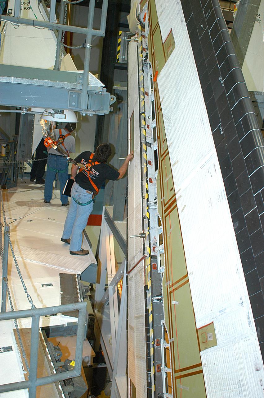
KENNEDY SPACE CENTER, FLA. -- In the Orbiter Processing Facility, a technician looks at the Rudder Speed Brake panel on the vertical tail of orbiter Atlantis. The Rudder Speed Brake is being removed for inspection and maintenance prior to Return to Flight. The vertical tail consists of a structural fin surface made of aluminum, the Rudder Speed Brake surface, a tip and a lower trailing edge. The rudder splits into two halves to serve as a speed brake. The vertical tail and Rudder Speed Brake are covered with a reusable thermal protection system. The Rudder Speed Brake is used to guide and slow the Shuttle as it comes in for a landing.
KENNEDY SPACE CENTER, FLA. -- In the Orbiter Processing Facility, workers connect a device onto the vertical tail of the orbiter Atlantis to remove the Rudder Speed Brake panel. The Rudder Speed Brake is being removed for inspection and maintenance prior to Return to Flight. The vertical tail consists of a structural fin surface made of aluminum, the Rudder Speed Brake surface, a tip and a lower trailing edge. The rudder splits into two halves to serve as a speed brake. The vertical tail and Rudder Speed Brake are covered with a reusable thermal protection system. The Rudder Speed Brake is used to guide and slow the Shuttle as it comes in for a landing.
KENNEDY SPACE CENTER, FLA. -- In the Orbiter Processing Facility, workers begin removing the Rudder Speed Brake panel on the vertical tail of the orbiter Atlantis. The Rudder Speed Brake is being removed for inspection and maintenance prior to Return to Flight. The vertical tail consists of a structural fin surface made of aluminum, the Rudder Speed Brake surface, a tip and a lower trailing edge. The rudder splits into two halves to serve as a speed brake. The vertical tail and Rudder Speed Brake are covered with a reusable thermal protection system. The Rudder Speed Brake is used to guide and slow the Shuttle as it comes in for a landing.
KENNEDY SPACE CENTER, FLA. -- Workers ensure the safe removal of a Rudder Speed Brake Actuator from the orbiter Atlantis. This and three other actuators are being shipped to the vendor for inspection. An actuator is a motor that moves the tail rudder back and forth to help steer it during landing and brake its speed. The vertical tail consists of a structural fin surface made of aluminum, the Rudder Speed Brake surface, a tip and a lower trailing edge. The rudder splits into two halves to serve as a speed brake. The vertical tail and Rudder Speed Brake are covered with a reusable thermal protection system. Atlantis is undergoing maintenance and inspection in the Orbiter Processing Facility for a future mission.
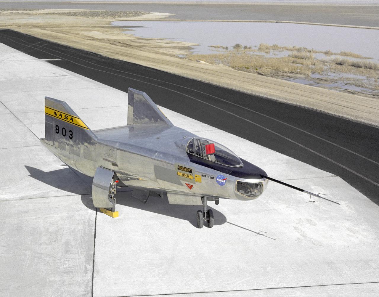
The M2-F2 Lifting Body is seen here on the ramp at the NASA Dryden Flight Research Center. The success of Dryden's M2-F1 program led to NASA's development and construction of two heavyweight lifting bodies based on studies at NASA's Ames and Langley research centers -- the M2-F2 and the HL-10, both built by the Northrop Corporation. The "M" refers to "manned" and "F" refers to "flight" version. "HL" comes from "horizontal landing" and 10 is for the tenth lifting body model to be investigated by Langley. The first flight of the M2-F2 -- which looked much like the "F1" -- was on July 12, 1966. Milt Thompson was the pilot. By then, the same B-52 used to air launch the famed X-15 rocket research aircraft was modified to also carry the lifting bodies. Thompson was dropped from the B-52's wing pylon mount at an altitude of 45,000 feet on that maiden glide flight. The M2-F2 weighed 4,620 pounds, was 22 feet long, and had a width of about 10 feet. On May 10, 1967, during the sixteenth glide flight leading up to powered flight, a landing accident severely damaged the vehicle and seriously injured the NASA pilot, Bruce Peterson. NASA pilots and researchers realized the M2-F2 had lateral control problems, even though it had a stability augmentation control system. When the M2-F2 was rebuilt at Dryden and redesignated the M2-F3, it was modified with an additional third vertical fin -- centered between the tip fins -- to improve control characteristics. The M2-F2/F3 was the first of the heavy-weight, entry-configuration lifting bodies. Its successful development as a research test vehicle answered many of the generic questions about these vehicles. NASA donated the M2-F3 vehicle to the Smithsonian Institute in December 1973. It is currently hanging in the Air and Space Museum along with the X-15 aircraft number 1, which was its hangar partner at Dryden from 1965 to 1969.
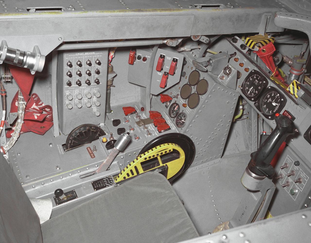
This photo shows the left side cockpit instrumentation panel of the M2-F2 Lifting Body. The success of Dryden's M2-F1 program led to NASA's development and construction of two heavyweight lifting bodies based on studies at NASA's Ames and Langley research centers -- the M2-F2 and the HL-10, both built by the Northrop Corporation. The "M" refers to "manned" and "F" refers to "flight" version. "HL" comes from "horizontal landing" and 10 is for the tenth lifting body model to be investigated by Langley. The first flight of the M2-F2 -- which looked much like the "F1" -- was on July 12, 1966. Milt Thompson was the pilot. By then, the same B-52 used to air launch the famed X-15 rocket research aircraft was modified to also carry the lifting bodies. Thompson was dropped from the B-52's wing pylon mount at an altitude of 45,000 feet on that maiden glide flight. The M2-F2 weighed 4,620 pounds, was 22 feet long, and had a width of about 10 feet. On May 10, 1967, during the sixteenth glide flight leading up to powered flight, a landing accident severely damaged the vehicle and seriously injured the NASA pilot, Bruce Peterson. NASA pilots and researchers realized the M2-F2 had lateral control problems, even though it had a stability augmentation control system. When the M2-F2 was rebuilt at Dryden and redesignated the M2-F3, it was modified with an additional third vertical fin -- centered between the tip fins -- to improve control characteristics. The M2-F2/F3 was the first of the heavy-weight, entry-configuration lifting bodies. Its successful development as a research test vehicle answered many of the generic questions about these vehicles. NASA donated the M2-F3 vehicle to the Smithsonian Institute in December 1973. It is currently hanging in the Air and Space Museum along with the X-15 aircraft number 1, which was its hangar partner at Dryden from 1965 to 1969.
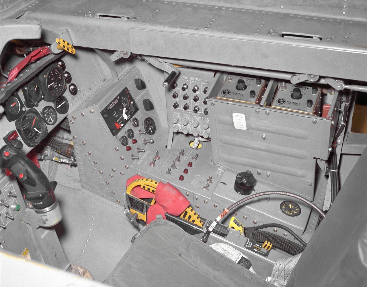
This photo shows the right side cockpit instrumentation panel of the M2-F2 Lifting Body. The success of Dryden's M2-F1 program led to NASA's development and construction of two heavyweight lifting bodies based on studies at NASA's Ames and Langley research centers -- the M2-F2 and the HL-10, both built by the Northrop Corporation. The "M" refers to "manned" and "F" refers to "flight" version. "HL" comes from "horizontal landing" and 10 is for the tenth lifting body model to be investigated by Langley. The first flight of the M2-F2 -- which looked much like the "F1" -- was on July 12, 1966. Milt Thompson was the pilot. By then, the same B-52 used to air launch the famed X-15 rocket research aircraft was modified to also carry the lifting bodies. Thompson was dropped from the B-52's wing pylon mount at an altitude of 45,000 feet on that maiden glide flight. The M2-F2 weighed 4,620 pounds, was 22 feet long, and had a width of about 10 feet. On May 10, 1967, during the sixteenth glide flight leading up to powered flight, a landing accident severely damaged the vehicle and seriously injured the NASA pilot, Bruce Peterson. NASA pilots and researchers realized the M2-F2 had lateral control problems, even though it had a stability augmentation control system. When the M2-F2 was rebuilt at Dryden and redesignated the M2-F3, it was modified with an additional third vertical fin -- centered between the tip fins -- to improve control characteristics. The M2-F2/F3 was the first of the heavy-weight, entry-configuration lifting bodies. Its successful development as a research test vehicle answered many of the generic questions about these vehicles. NASA donated the M2-F3 vehicle to the Smithsonian Institute in December 1973. It is currently hanging in the Air and Space Museum along with the X-15 aircraft number 1, which was its hangar partner at Dryden from 1965 to 1969.
The Hyper III was a low-cost test vehicle for an advanced lifting-body shape. Like the earlier M2-F1, it was a "homebuilt" research aircraft, i.e., built at the Flight Research Center (FRC), later redesignated the Dryden Flight Research Center. It had a steel-tube frame covered with Dacron, a fiberglass nose, sheet aluminum fins, and a wing from an HP-11 sailplane. Construction was by volunteers at the FRC. Although the Hyper III was to be flown remotely in its initial tests, it was fitted with a cockpit for a pilot. On the Hyper III's only flight, it was towed aloft attached to a Navy SH-3 helicopter by a 400-foot cable. NASA research pilot Bruce Peterson flew the SH-3. After he released the Hyper III from the cable, NASA research pilot Milt Thompson flew the vehicle by radio control until the final approach when Dick Fischer took over control using a model-airplane radio-control box. The Hyper III flared, then landed and slid to a stop on Rogers Dry Lakebed.
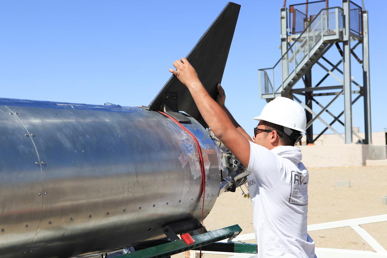
MOJAVE DESERT, Calif. – In the Mojave Desert in California, a student attaches a tail fin to the Garvey Spacecraft Corporation's Prospector P-18D rocket at the Friends of Amateur Rocketry launch site. The rocket is scheduled for flight June 15 with the RUBICS-1 payload on a high-altitude, suborbital flight. The rocket will carry four satellites made from four-inch cube sections. Collectively known as CubeSats, the satellites will record shock, vibrations and heat inside the rocket. They will not be released during the test flight, but the results will be used to prove or strengthen their designs before they are carried into orbit in 2014 on a much larger rocket. A new, lightweight carrier is also being tested for use on future missions to deploy the small spacecraft. The flight also is being watched closely as a model for trying out new or off-the-shelf technologies quickly before putting them in the pipeline for use on NASA's largest launchers. Built by several different organizations, including a university, a NASA field center and a high school, the spacecraft are four-inch cubes designed to fly on their own eventually, but will remain firmly attached to the rocket during the upcoming mission. For more information, visit http://www.nasa.gov/mission_pages/smallsats/elana/cubesatlaunchpreview.html Photo credit: NASA/Dimitri Gerondidakis
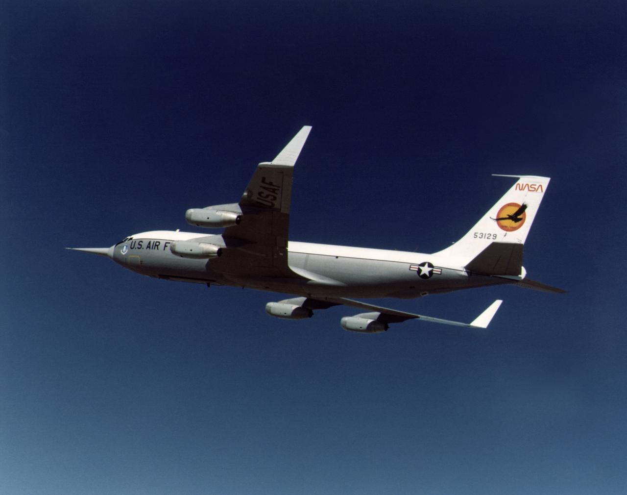
During the 1970s, the focus at Dryden shifted from high-speed and high-altitude flight to incremental improvements in technology and aircraft efficiency. One manifestation of this trend occurred in the winglet flight research carried out on a KC-135 during 1979 and 1980. Richard Whitcomb at the Langley Research Center had originated the idea of adding small vertical fins to an aircraft's wing tips. His wind tunnel tests indicated that winglets produced a forward thrust, which reduced the strength of the vortices generated by an aircraft's wing tips and resulted in a reduction of drag and an increase in aircraft range. Whitcomb, who had previously developed the area rule concept and the supercritical wing, selected the best winglet shape for flight tests on a KC-135 tanker. When the tests were completed, the data showed that the winglets provided a 7 percent improvement in range over the standard KC-135. The obvious economic advantage at a time of high fuel costs caused winglets to be adopted on business jets, airliners, and heavy military transports.
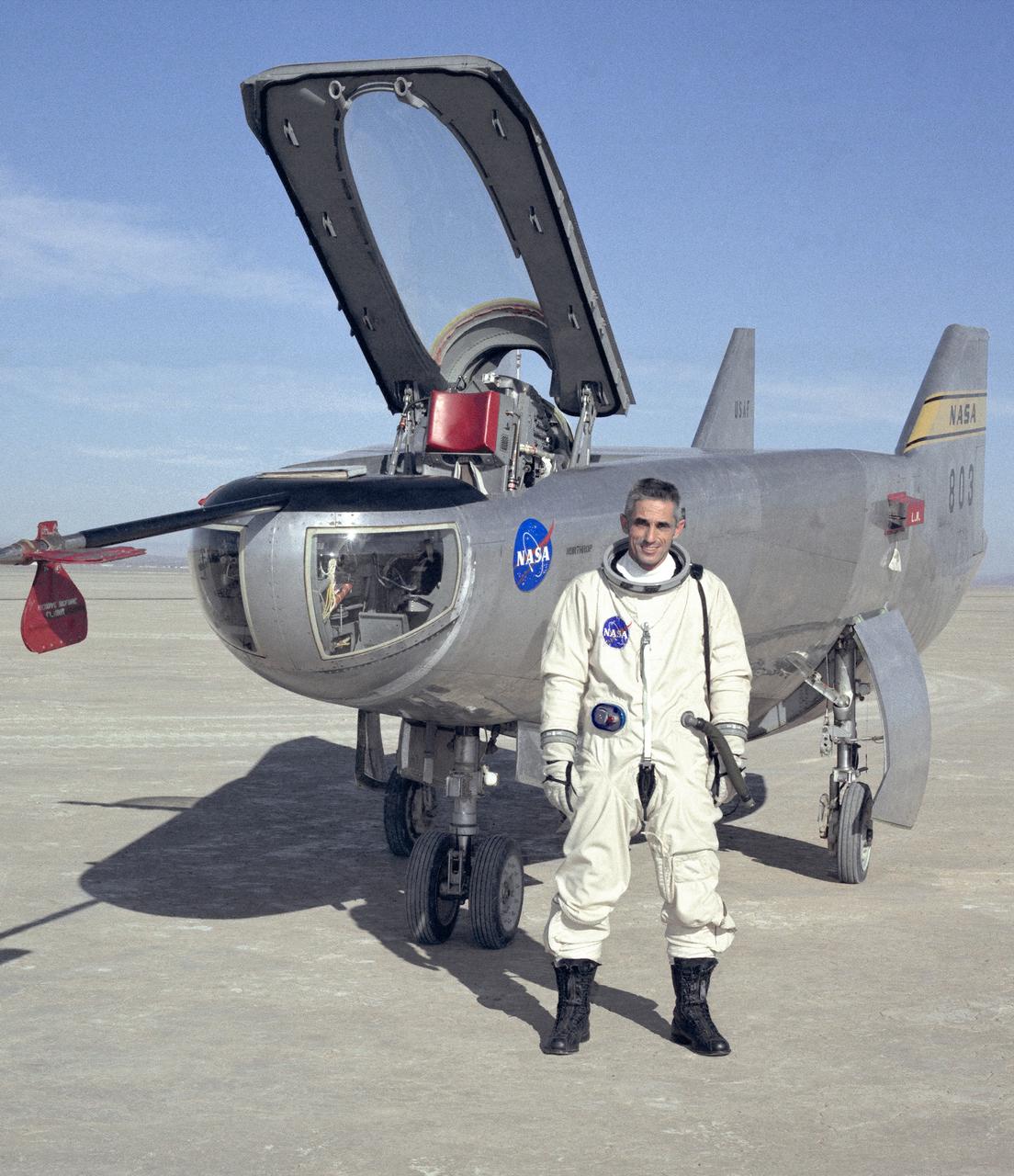
NASA research pilot John A. Manke is seen here in front of the M2-F3 Lifting Body. Manke was hired by NASA on May 25, 1962, as a flight research engineer. He was later assigned to the pilot's office and flew various support aircraft including the F-104, F5D, F-111 and C-47. After leaving the Marine Corps in 1960, Manke worked for Honeywell Corporation as a test engineer for two years before coming to NASA. He was project pilot on the X-24B and also flew the HL-10, M2-F3, and X-24A lifting bodies. John made the first supersonic flight of a lifting body and the first landing of a lifting body on a hard surface runway. Manke served as Director of the Flight Operations and Support Directorate at the Dryden Flight Research Center prior to its integration with Ames Research Center in October 1981. After this date John was named to head the joint Ames-Dryden Directorate of Flight Operations. He also served as site manager of the NASA Ames-Dryden Flight Research Facility. John is a member of the Society of Experimental Test Pilots. He retired on April 27, 1984.
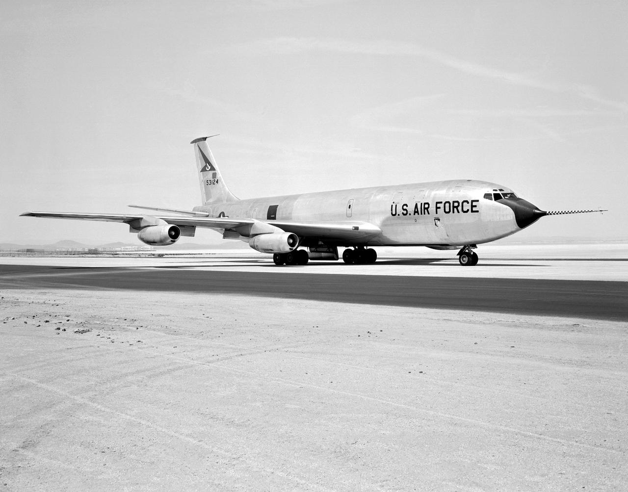
The Boeing KC-135 Stratotanker, besides being used extensively in its primary role as an inflight aircraft refueler, has assisted in several projects at the NASA Dryden Flight Research Center, Edwards, California. In 1957 and 1958, Dryden was asked by what was then the Civil Aeronautics Administration (later absorbed into the Federal Aviation Administration (FAA) in 1958) to help establish new approach procedure guidelines on cloud-ceiling and visibility minimums for Boeing's first jet airliner, the B-707. Dryden used a KC-135 (the military variant of the 707), seen here on the runway at Edwards Air Force Base, to aid the CAA in these tests. In 1979 and 1980, Dryden was again involved with general aviation research with the KC-135. This time, a special wingtip "winglet", developed by Richard Whitcomb of Langley Research Center, was tested on the jet aircraft. Winglets are small, nearly vertical fins installed on an airplane's wing tips to help produce a forward thrust in the vortices that typically swirl off the end of the wing, thereby reducing drag. This winglet idea was tested at the Dryden Flight Research Center on a KC-135A tanker loaned to NASA by the Air Force. The research showed that the winglets could increase an aircraft's range by as much as 7 percent at cruise speeds. The first application of NASA's winglet technology in industry was in general aviation business jets, but winglets are now being incorporated into most new commercial and military transport jets, including the Gulfstream III and IV business jets, the Boeing 747-400 and MD-11 airliners, and the C-17 military transport. In the 1980's, a KC-135 was used in support of the Space Shuttle program. Since the Shuttle was to be launched from Florida, researchers wanted to test the effect of rain on the sensitive thermal tiles. Tiles were mounted on special fixtures on an F-104 aircraft and a P-3 Orion. The F-104 was flown in actual rain conditions, and also behind the KC-135 spray tanker as it rel
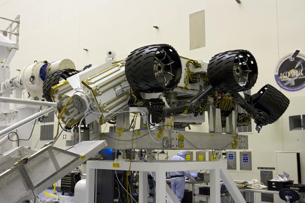
CAPE CANAVERAL, Fla. -- In the high bay of the Payload Hazardous Servicing Facility (PHSF) at NASA's Kennedy Space Center in Florida, the multi-mission radioisotope thermoelectric generator (MMRTG) for NASA's Mars Science Laboratory (MSL) mission is installed onto the aft of the Curiosity rover for a fit check. In view are the MMRTG's cooling fins which function like the radiator on a car and will reflect any excess heat generated by the MMRTG to prevent interference with the rover's electronics. Next, the MMRTG will be removed and later installed on the rover for launch at the pad. The MMRTG will generate the power needed for the mission from the natural decay of plutonium-238, a non-weapons-grade form of the radioisotope. Heat given off by this natural decay will provide constant power through the day and night during all seasons. Curiosity, MSL's car-sized rover, has 10 science instruments designed to search for signs of life, including methane, and help determine if the gas is from a biological or geological source. Waste heat from the MMRTG will be circulated throughout the rover system to keep instruments, computers, mechanical devices and communications systems within their operating temperature ranges. Launch of MSL aboard a United Launch Alliance Atlas V rocket is planned for Nov. 25 from Space Launch Complex 41 on Cape Canaveral Air Force Station. For more information, visit http://www.nasa.gov/msl. Photo credit: NASA/Cory Huston
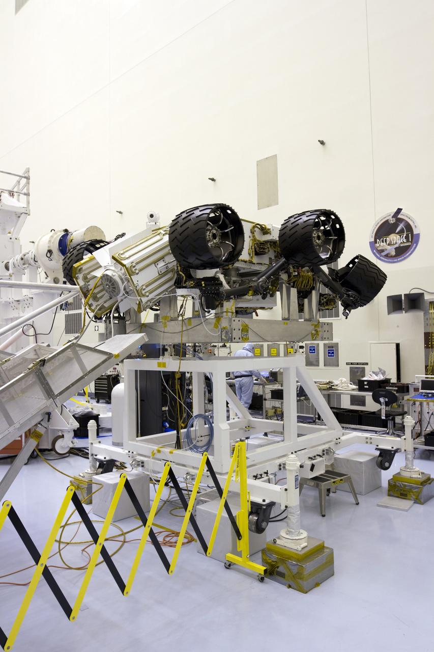
CAPE CANAVERAL, Fla. -- In the high bay of the Payload Hazardous Servicing Facility (PHSF) at NASA's Kennedy Space Center in Florida, the multi-mission radioisotope thermoelectric generator (MMRTG) for NASA's Mars Science Laboratory (MSL) mission is installed onto the aft of the Curiosity rover for a fit check. In view are the MMRTG's cooling fins which function like the radiator on a car and will reflect any excess heat generated by the MMRTG to prevent interference with the rover's electronics. Next, the MMRTG will be removed and later installed on the rover for launch at the pad. The MMRTG will generate the power needed for the mission from the natural decay of plutonium-238, a non-weapons-grade form of the radioisotope. Heat given off by this natural decay will provide constant power through the day and night during all seasons. Curiosity, MSL's car-sized rover, has 10 science instruments designed to search for signs of life, including methane, and help determine if the gas is from a biological or geological source. Waste heat from the MMRTG will be circulated throughout the rover system to keep instruments, computers, mechanical devices and communications systems within their operating temperature ranges. Launch of MSL aboard a United Launch Alliance Atlas V rocket is planned for Nov. 25 from Space Launch Complex 41 on Cape Canaveral Air Force Station. For more information, visit http://www.nasa.gov/msl. Photo credit: NASA/Cory Huston
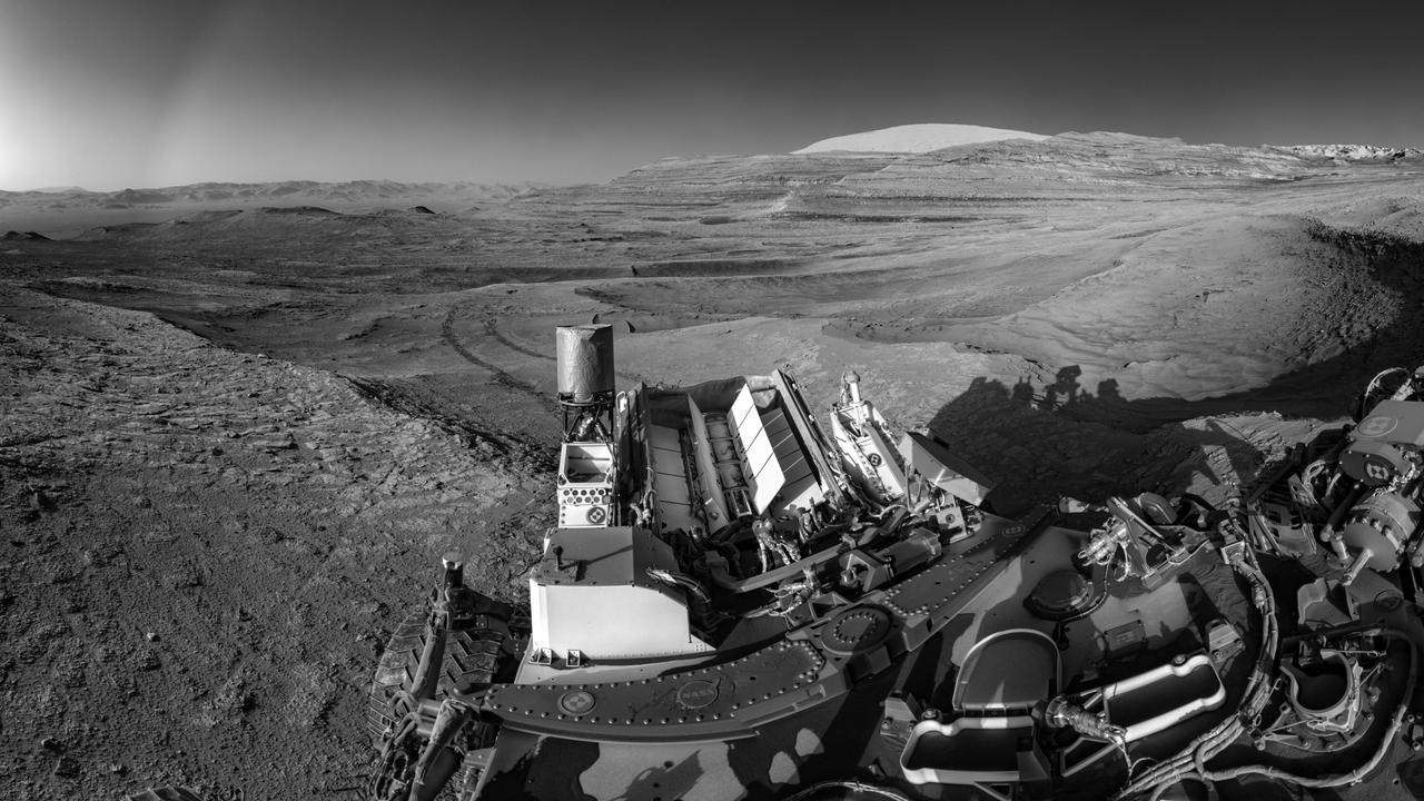
NASA's Curiosity Mars rover demonstrated a new multitasking capability when capturing this view: It snapped the 15 images that make up the mosaic while simultaneously communicating with an orbiter. The images were taken by the right navigation camera on Curiosity's mast July 26, 2025, the 4,611th sol, or day, of the mission. The rover's tracks cross through a region filled with boxwork formations – hardened ridges created by mineral deposits from subsurface water billions of years ago. This boxwork region is in the lower foothills of Mount Sharp, a 3-mile-tall (5-kilometer-tall) mountain in the center of Gale Crater. Being able to combine tasks shortens the rover's daily plan, requiring less power from Curiosity's nuclear power source, called a multi-mission radioisotope thermonuclear generator (MMRTG), which is lined with rows of white fins at the back of the rover. NASA's Perseverance rover is also equipped with an MMRTG; the generator uses the heat from decaying plutonium pellets to charge batteries on the rovers. The can-like cylinder to the left of the MMRTG is Curiosity's ultrahigh frequency (UHF) antenna, which communicates with spacecraft in orbit around Mars. To capture a mosaic like this, the rover would normally require nine minutes of awake time devoted solely to imaging. However, while snapping the images for this mosaic, Curiosity was also sending data to ESA's (the European Space Agency's) Trace Gas Orbiter, essentially saving several minutes of battery time. After being sent to Earth, the images were stitched together and the seams between them smoothed out before the mosaic was processed to enhance details. https://photojournal.jpl.nasa.gov/catalog/PIA26632
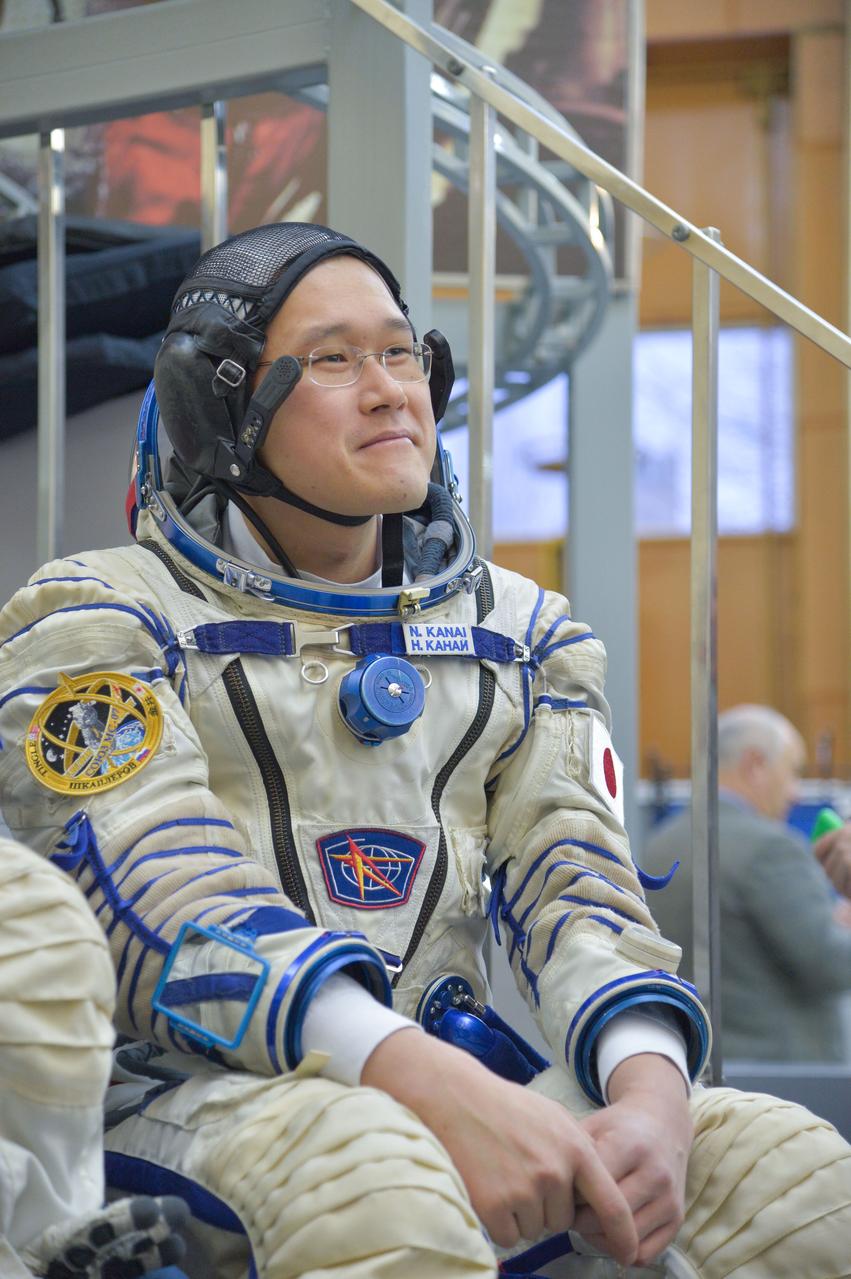
jsc2017e135207 - At the Gagarin Cosmonaut Training Center in Star City, Russia, Expedition 54-55 prime crewmember Norishige Kanai of the Japan Aerospace Exploration Space Agency (JAXA) listens to a reporters’ question Nov. 29 as part of the crew’s final qualification exam activities. Kanai, Scott Tingle of NASA and Anton Shkaplerov of the Russian Federal Space Agency (Roscosmos) will launch Dec. 17 on the Soyuz MS-07 spacecraft from the Baikonur Cosmodrome in Kazakhstan for a five-month mission on the International Space Station...NASA/Elizabeth Weissinger.
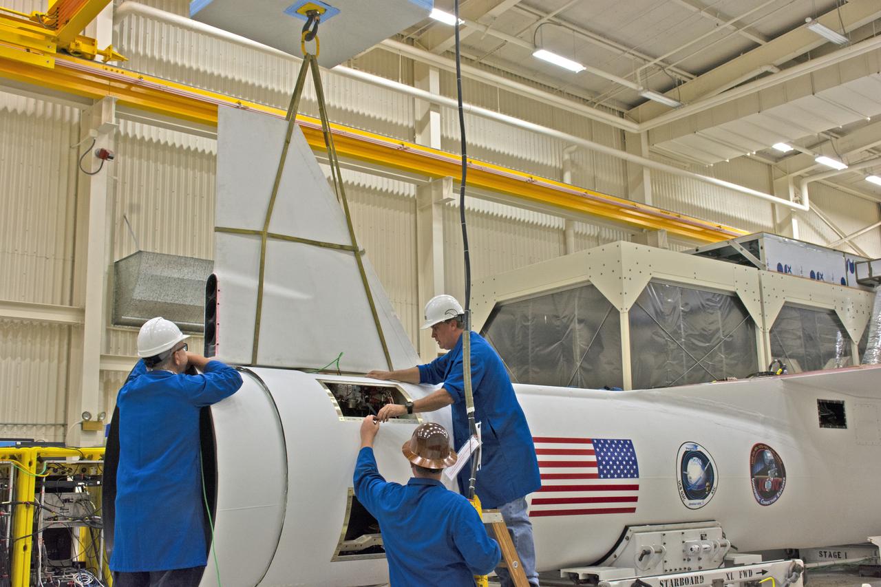
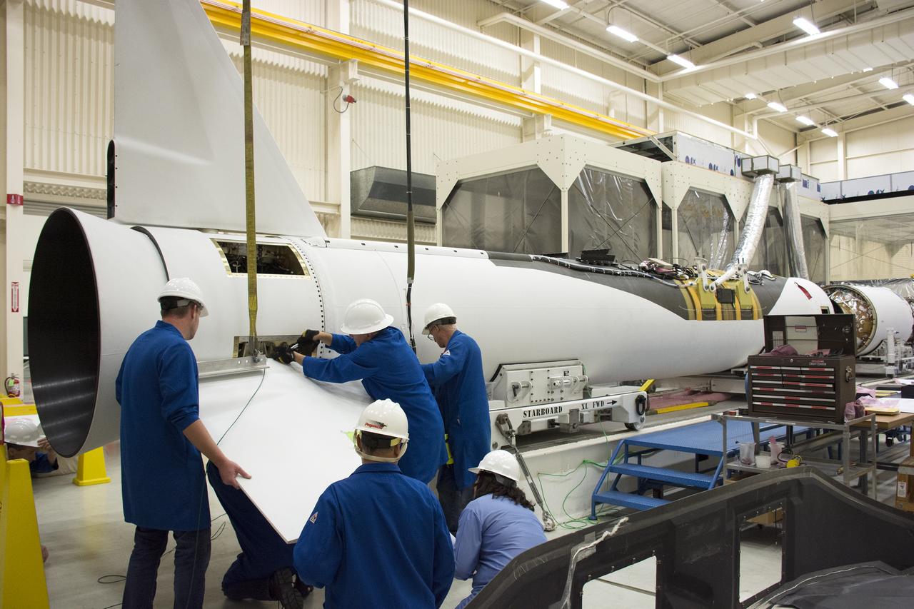
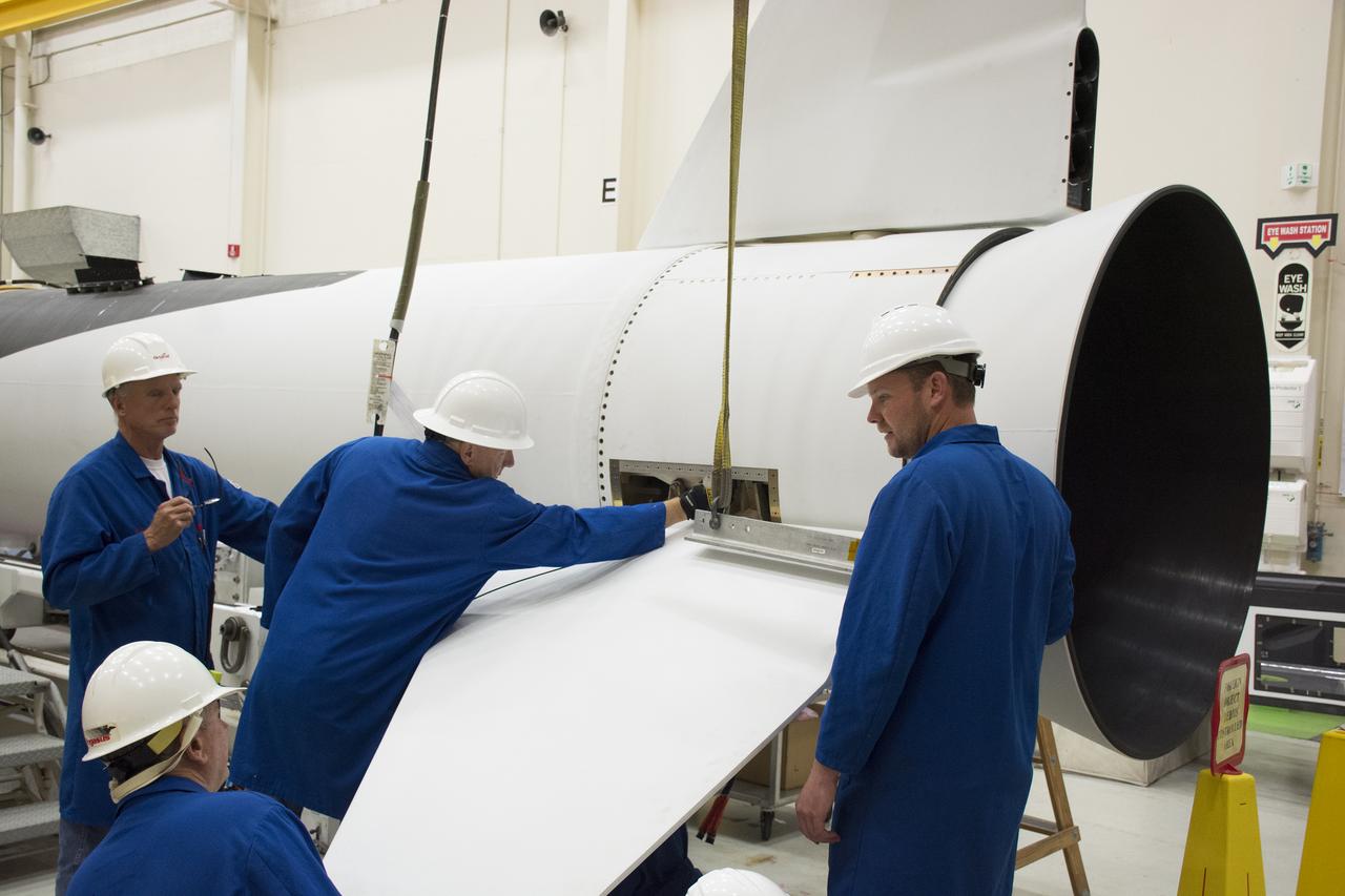
Inside Building 1555 at Vandenberg Air Force Base in California, technicians install the first of two fins on Northrop Grumman's Pegasus XL rocket on July 30, 2018. The Pegasus XL rocket, attached beneath the company's L-1011 Stargazer aircraft, will launch NASA's Ionospheric Connection Explorer (ICON) from the Skid Strip at Cape Canaveral Air Force Station in Florida. Launch is scheduled for Oct. 26. ICON will study the frontier of space - the dynamic zone high in Earth's atmosphere where terrestrial weather from below meets space weather above. The explorer will help determine the physics of Earth's space environment and pave the way for mitigating its effects on our technology, communications systems and society.
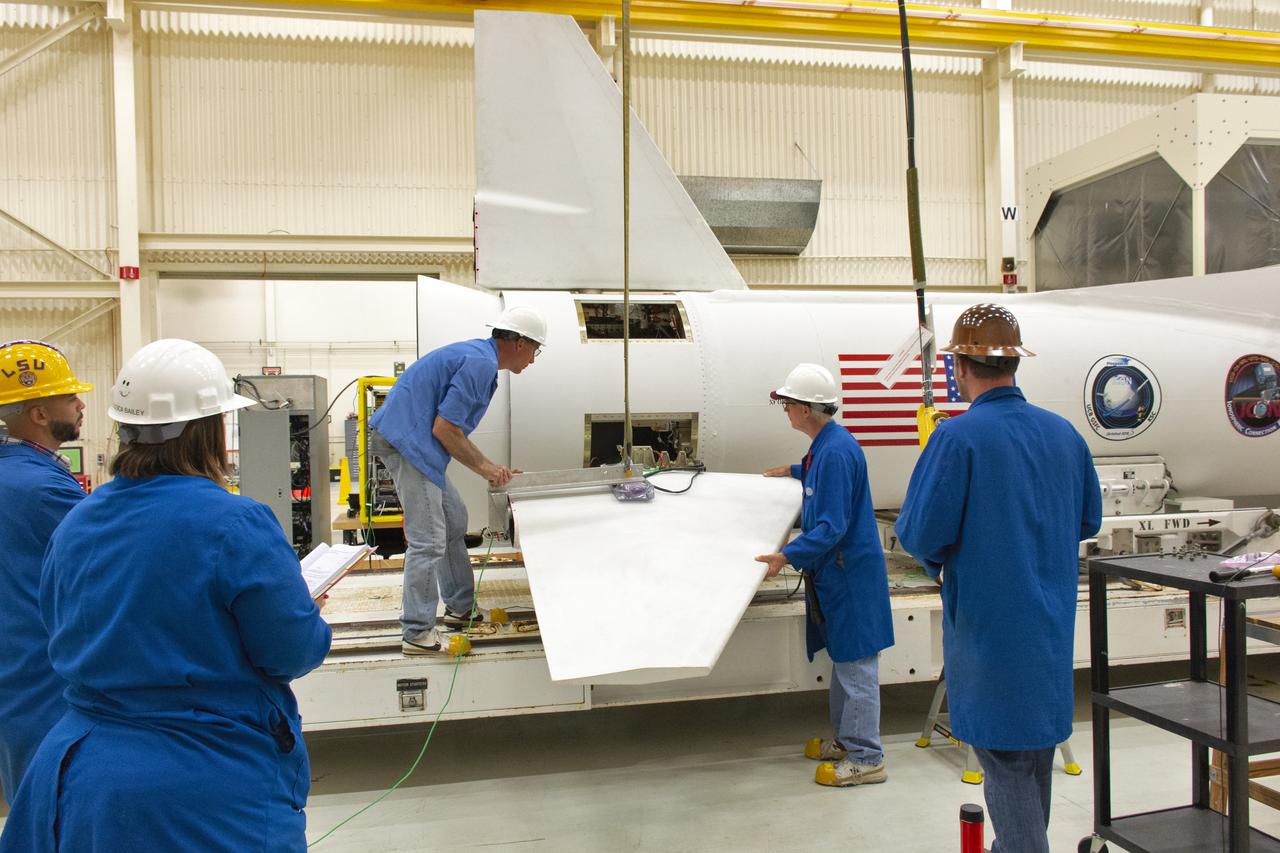
Inside Building 1555 at Vandenberg Air Force Base in California, technicians prepare to install the second of two fins on Northrop Grumman's Pegasus XL rocket on July 30, 2018. The Pegasus XL rocket, attached beneath the company's L-1011 Stargazer aircraft, will launch NASA's Ionospheric Connection Explorer (ICON) from the Skid Strip at Cape Canaveral Air Force Station in Florida. Launch is scheduled for Oct. 26. ICON will study the frontier of space - the dynamic zone high in Earth's atmosphere where terrestrial weather from below meets space weather above. The explorer will help determine the physics of Earth's space environment and pave the way for mitigating its effects on our technology, communications systems and society.
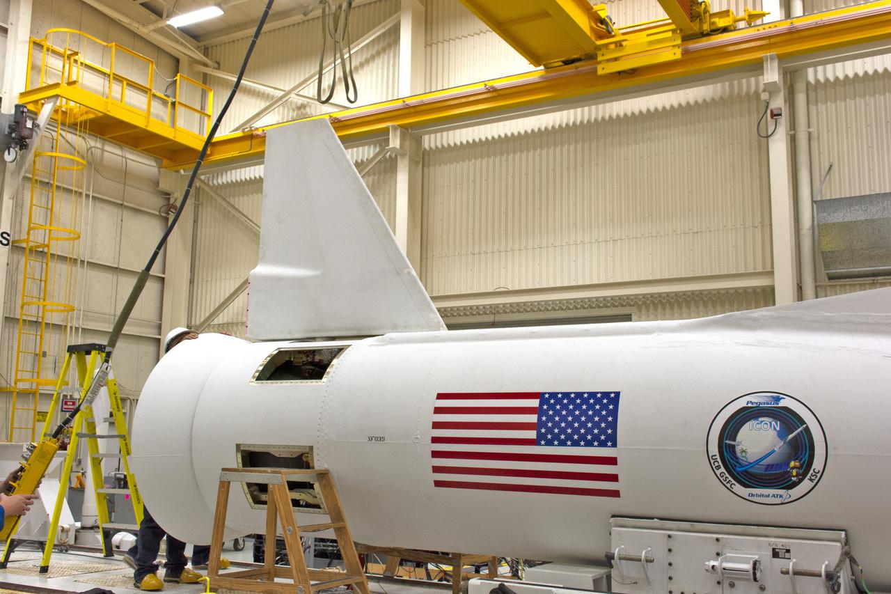
Inside Building 1555 at Vandenberg Air Force Base in California, technicians install the first of two fins on Northrop Grumman's Pegasus XL rocket on July 30, 2018. The Pegasus XL rocket, attached beneath the company's L-1011 Stargazer aircraft, will launch NASA's Ionospheric Connection Explorer (ICON) from the Skid Strip at Cape Canaveral Air Force Station in Florida. Launch is scheduled for Oct. 26. ICON will study the frontier of space - the dynamic zone high in Earth's atmosphere where terrestrial weather from below meets space weather above. The explorer will help determine the physics of Earth's space environment and pave the way for mitigating its effects on our technology, communications systems and society.
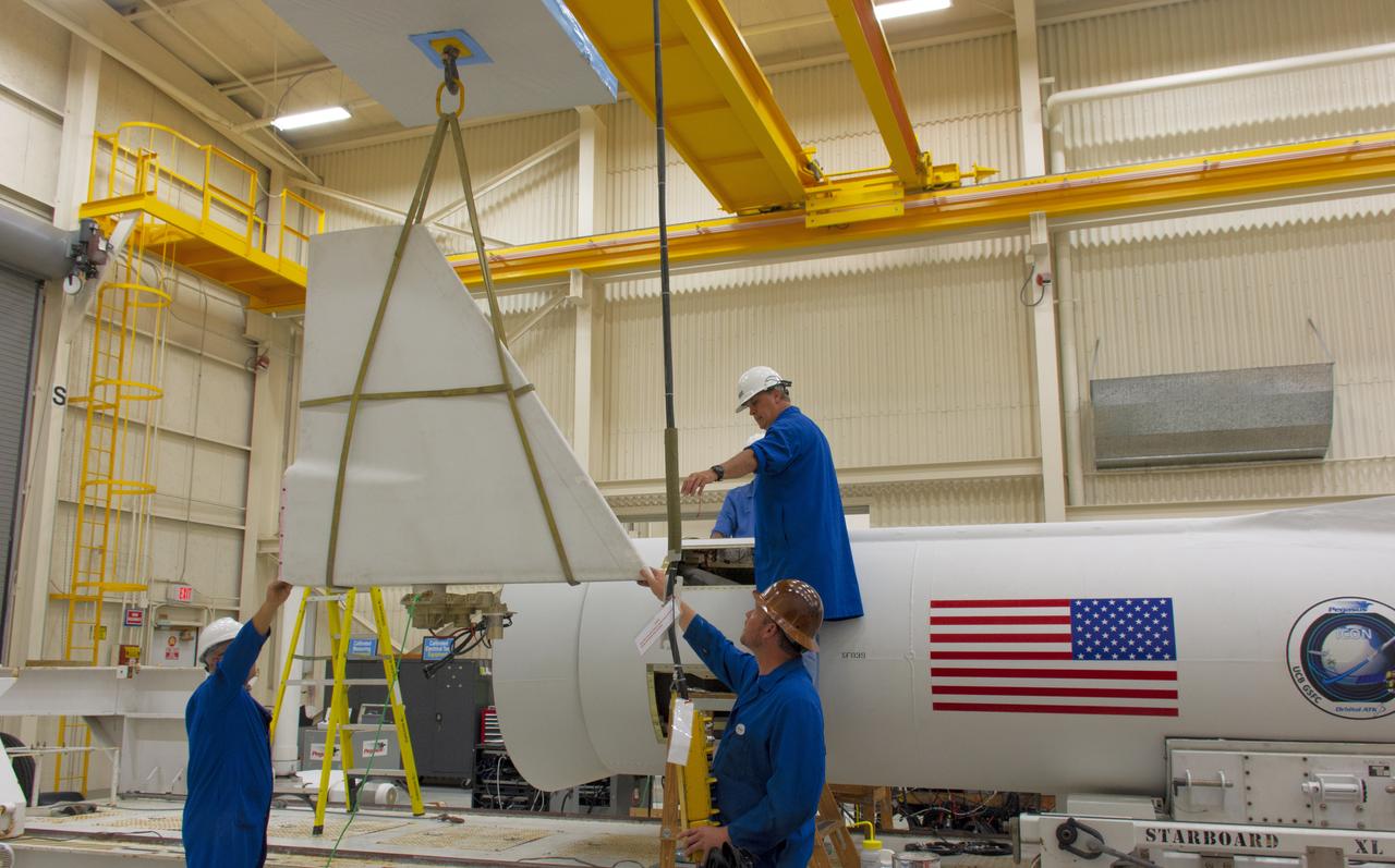
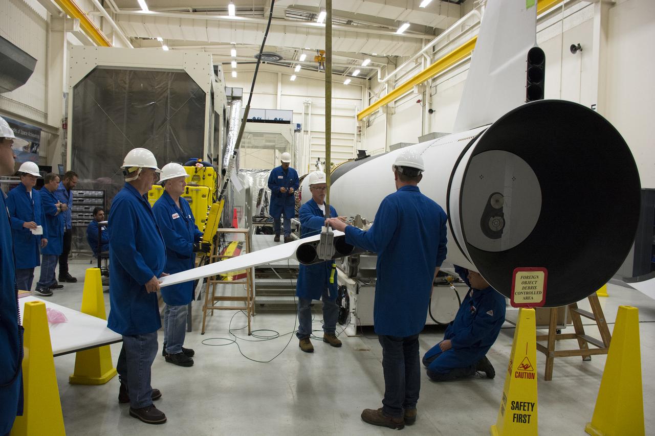
Inside Building 1555 at Vandenberg Air Force Base in California, technicians prepare to install the first of two fins on Northrop Grumman's Pegasus XL rocket on July 30, 2018. The Pegasus XL rocket, attached beneath the company's L-1011 Stargazer aircraft, will launch NASA's Ionospheric Connection Explorer (ICON) from the Skid Strip at Cape Canaveral Air Force Station in Florida. Launch is scheduled for Oct. 26. ICON will study the frontier of space - the dynamic zone high in Earth's atmosphere where terrestrial weather from below meets space weather above. The explorer will help determine the physics of Earth's space environment and pave the way for mitigating its effects on our technology, communications systems and society.
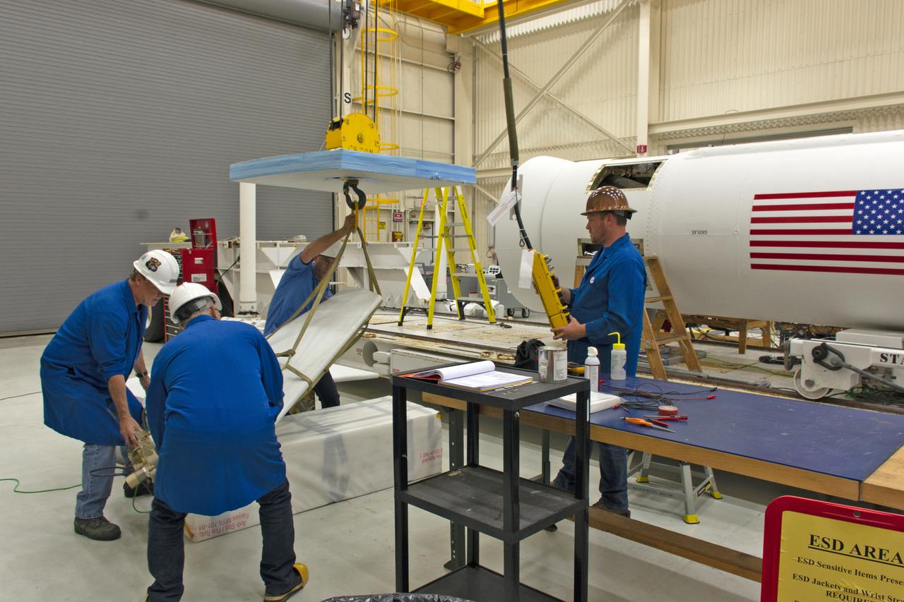
Inside Building 1555 at Vandenberg Air Force Base in California, technicians prepare the fins for installation on Northrop Grumman's Pegasus XL rocket on July 30, 2018. The Pegasus XL rocket, attached beneath the company's L-1011 Stargazer aircraft, will launch NASA's Ionospheric Connection Explorer (ICON) from the Skid Strip at Cape Canaveral Air Force Station in Florida. Launch is scheduled for Oct. 26. ICON will study the frontier of space - the dynamic zone high in Earth's atmosphere where terrestrial weather from below meets space weather above. The explorer will help determine the physics of Earth's space environment and pave the way for mitigating its effects on our technology, communications systems and society.
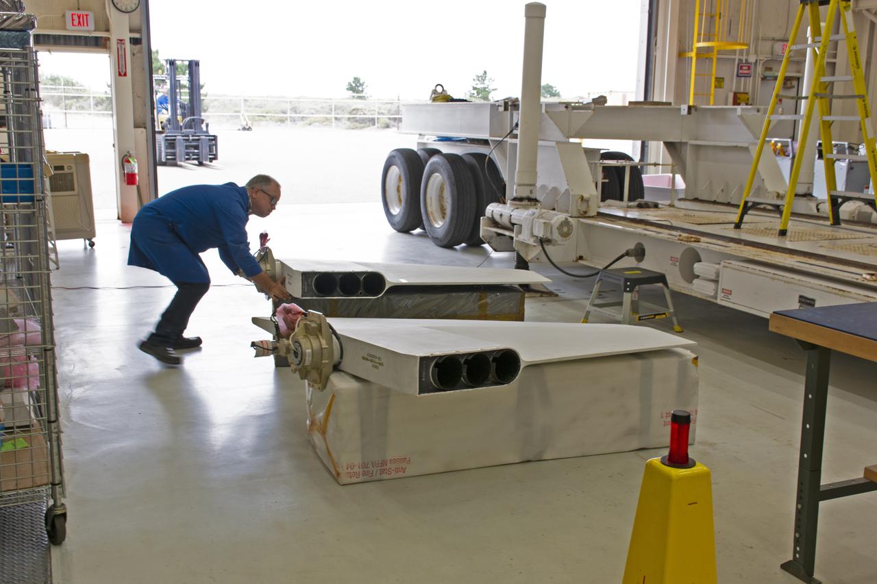
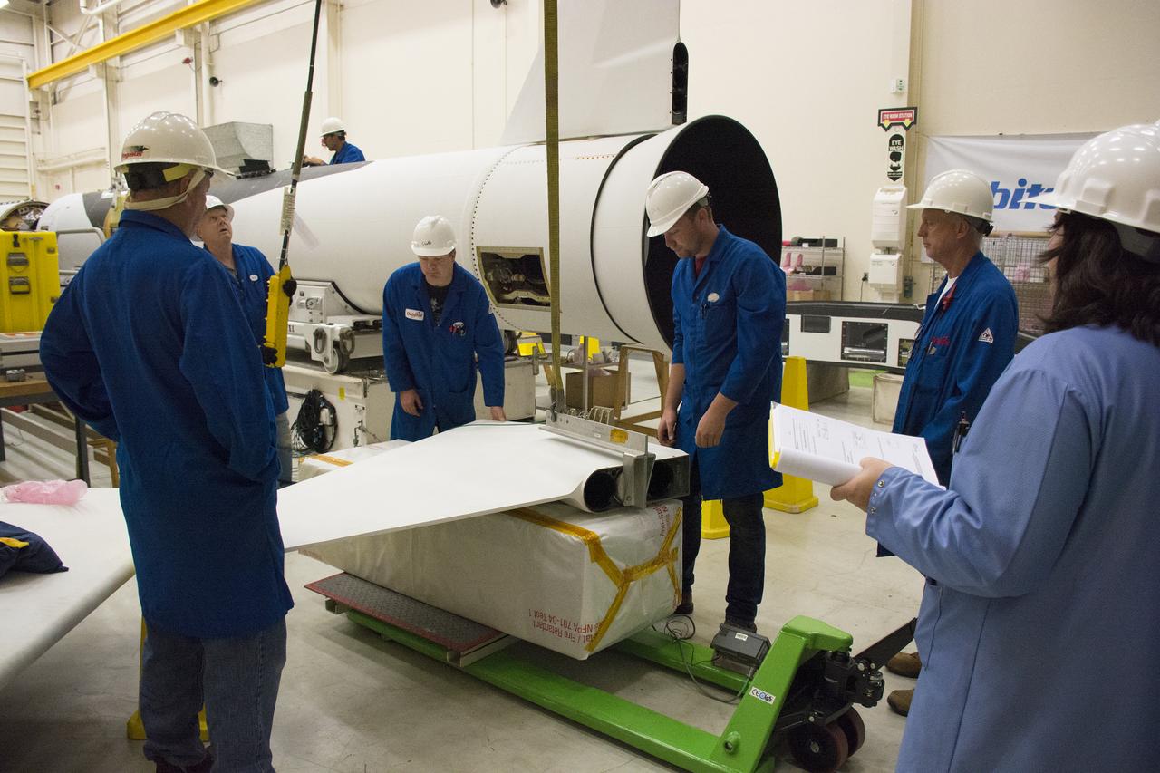
The fins for Northrop Grumman's Pegasus XL rocket arrive at Building 1555 at Vandenberg Air Force Base in California, on July 30, 2018. Technicians will prepare the fins for installation on the Pegasus XL rocket, which will be attached beneath the company's L-1011 Stargazer aircraft, to launch NASA's Ionospheric Connection Explorer (ICON) from the Skid Strip at Cape Canaveral Air Force Station in Florida. Launch is scheduled for Oct. 26. ICON will study the frontier of space - the dynamic zone high in Earth's atmosphere where terrestrial weather from below meets space weather above. The explorer will help determine the physics of Earth's space environment and pave the way for mitigating its effects on our technology, communications systems and society.
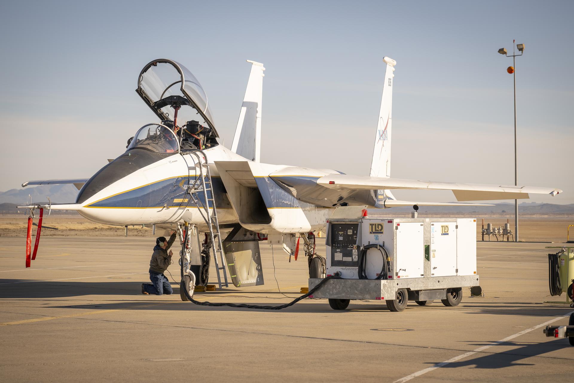
NASA ground crew prepares the agency’s F-15 research aircraft and Cross Flow Attenuated Natural Laminar Flow (CATNLF) test article ahead of its first high-speed taxi test on Tuesday, Jan. 12, 2026, at NASA’s Armstrong Flight Research Center in Edwards, California. The CATNLF design aims to reduce drag on wing surfaces to improve efficiency and, in turn, reduce fuel burn.
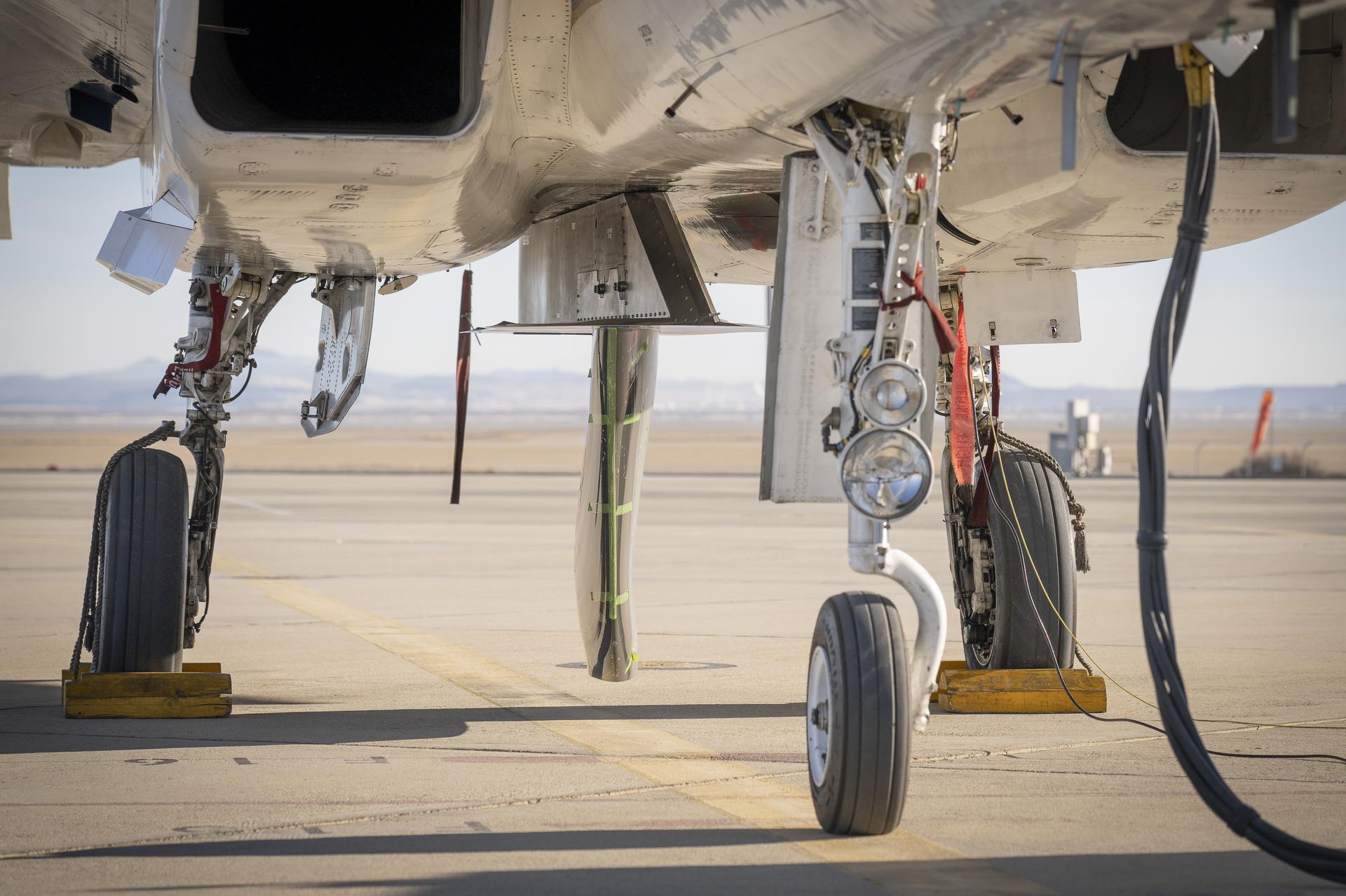
NASA’s Cross Flow Attenuated Natural Laminar Flow test article is mounted beneath the agency’s F-15 research aircraft ahead of the design’s high-speed taxi test on Tuesday, Jan. 12, 2026, at NASA’s Armstrong Flight Research Center in Edwards, California. The 3-foot-tall scale model is designed to increase a phenomenon known as laminar flow and reduce drag, improving efficiency in large, swept wings like those found on most commercial aircraft.
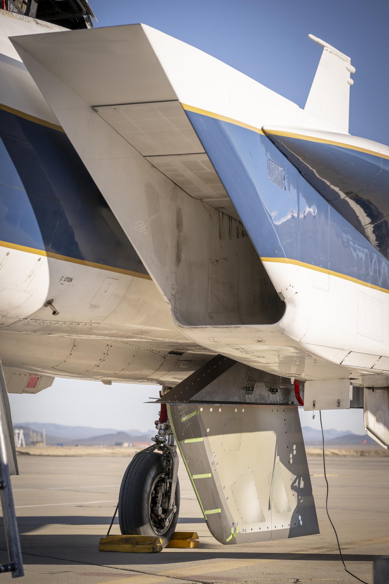
NASA’s Cross Flow Attenuated Natural Laminar Flow test article is mounted beneath the agency’s F-15 research aircraft ahead of the design’s high-speed taxi test on Tuesday, Jan. 12, 2026, at NASA’s Armstrong Flight Research Center in Edwards, California. The 3-foot-tall scale model is designed to increase a phenomenon known as laminar flow and reduce drag, improving efficiency in large, swept wings like those found on most commercial aircraft.
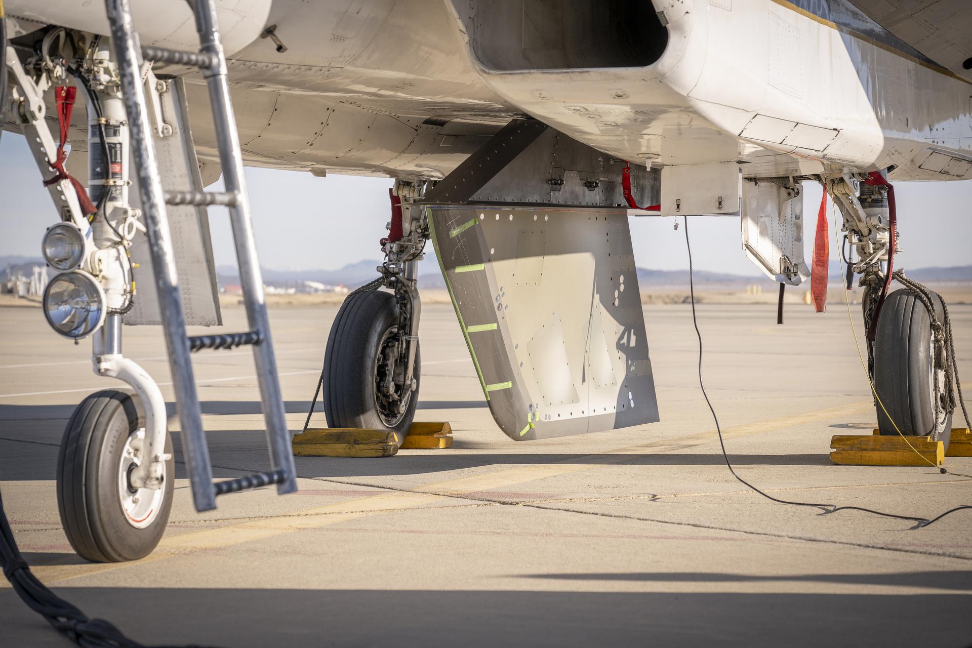
NASA’s Cross Flow Attenuated Natural Laminar Flow test article is mounted beneath the agency’s F-15 research aircraft ahead of the design’s high-speed taxi test on Tuesday, Jan. 12, 2026, at NASA’s Armstrong Flight Research Center in Edwards, California. The 3-foot-tall scale model is designed to increase a phenomenon known as laminar flow and reduce drag, improving efficiency in large, swept wings like those found on most commercial aircraft.
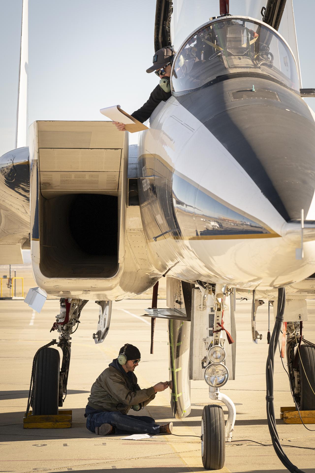
NASA ground crew prepares the agency’s F-15 research aircraft and Cross Flow Attenuated Natural Laminar Flow (CATNLF) test article ahead of its first high-speed taxi test on Tuesday, Jan. 12, 2026, at NASA’s Armstrong Flight Research Center in Edwards, California. The CATNLF design aims to reduce drag on wing surfaces to improve efficiency and, in turn, reduce fuel burn.
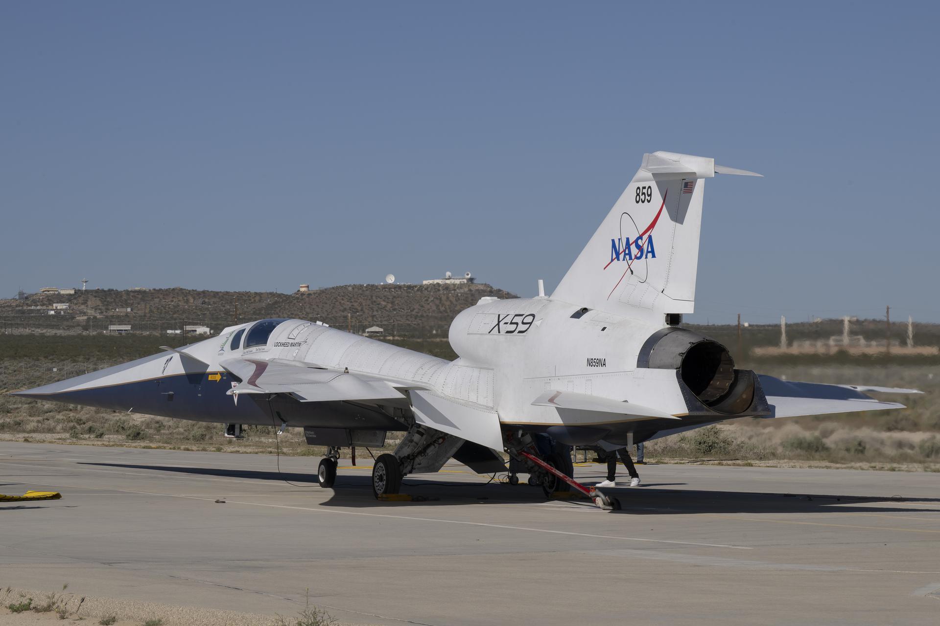
NASA’s X-59 quiet supersonic research aircraft completed a series of engine run tests on Thursday, March 12, 2026, at NASA’s Armstrong Flight Research Center in Edwards, California. These tests mark one of the final ground preparations before the aircraft’s second flight.