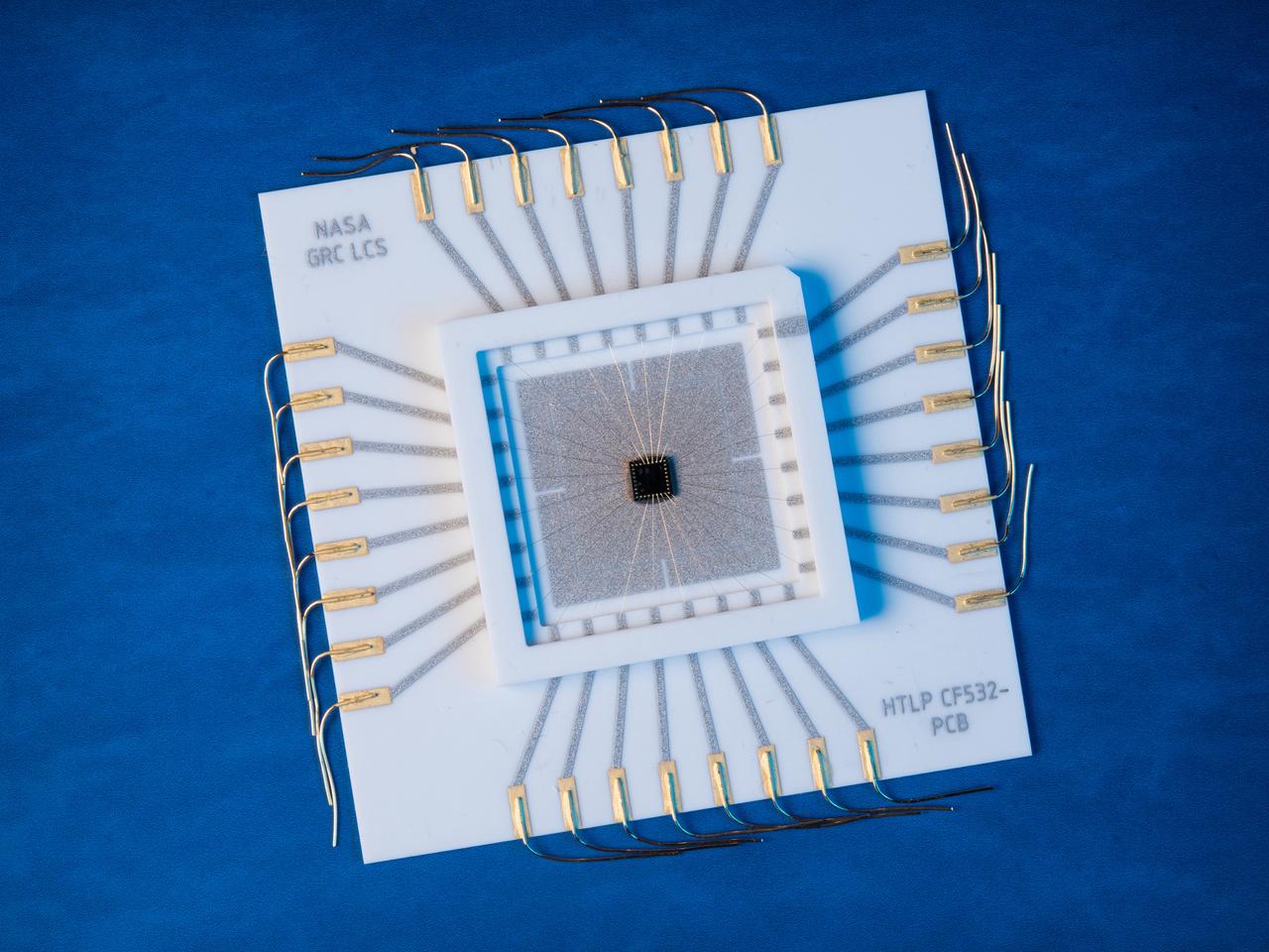
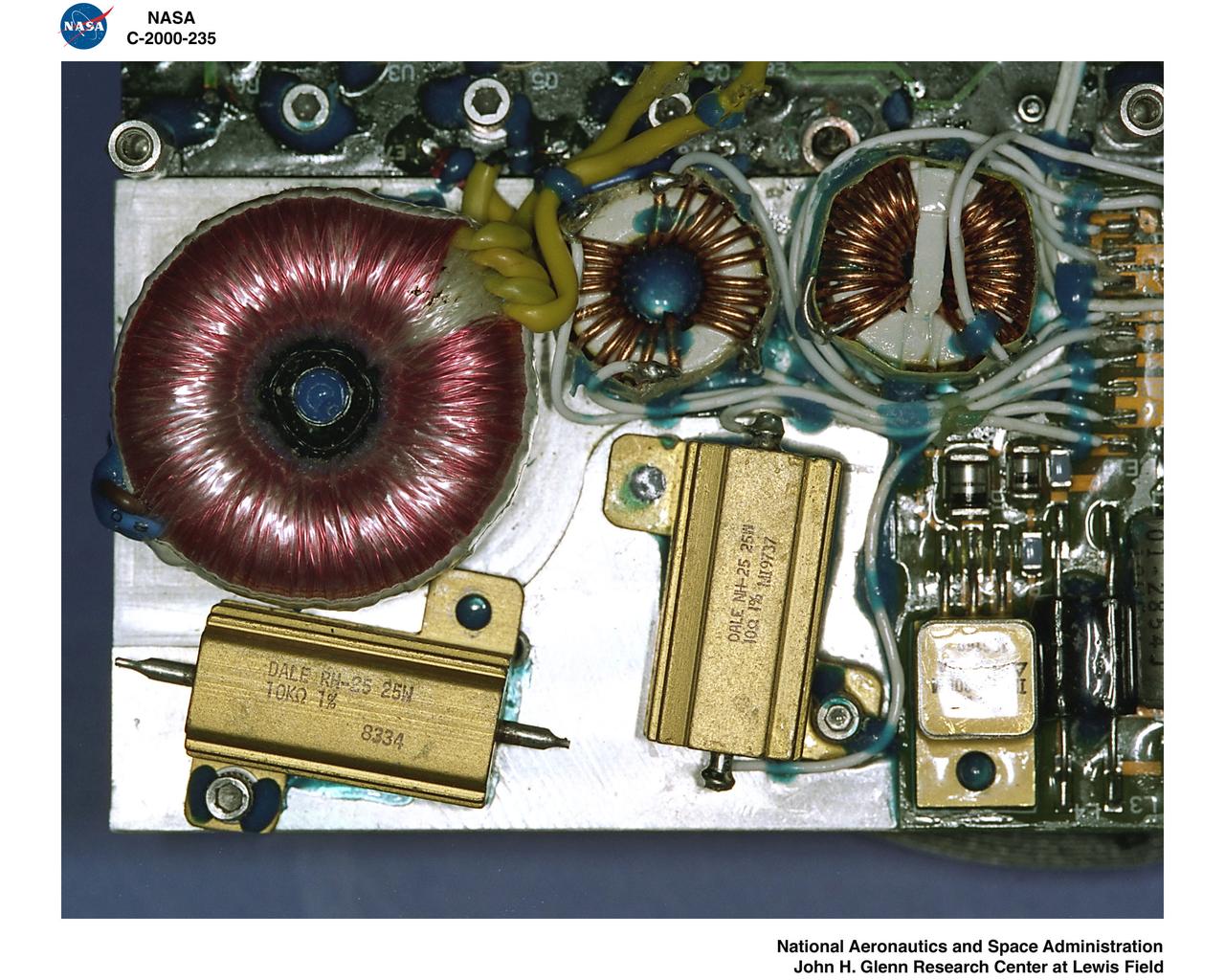
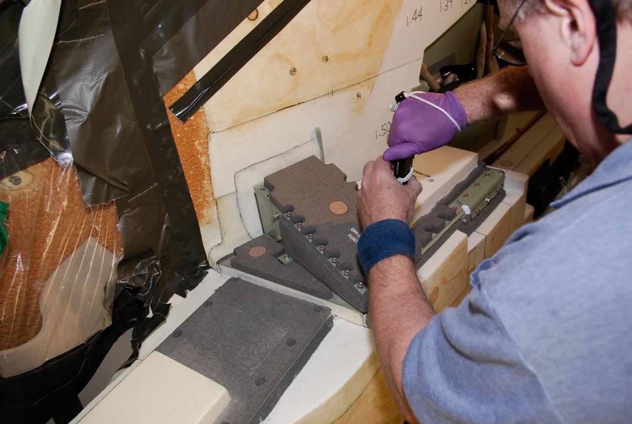
A multilevel interconnect silicon carbide integrated circuit chip with co-fired ceramic package and circuit board recently developed at the NASA GRC Smart Sensors and Electronics Systems Branch for high temperature applications. High temperature silicon carbide electronics and compatible packaging technologies are elements of instrumentation for aerospace engine control and long term inner-solar planet explorations.
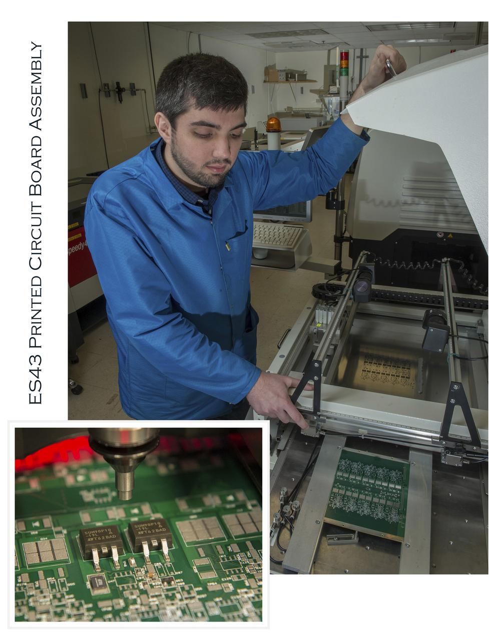
ES43 PRINTED CIRCUIT BOARD ASSEMBLY, JACOB HARPER
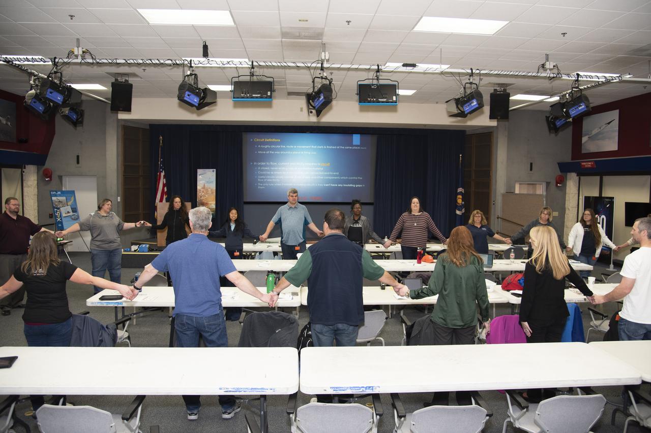
Barbara Buckner, NASA Armstrong's educator professional development specialist, leads a group exercise to form a human circuit to power an electric ball.

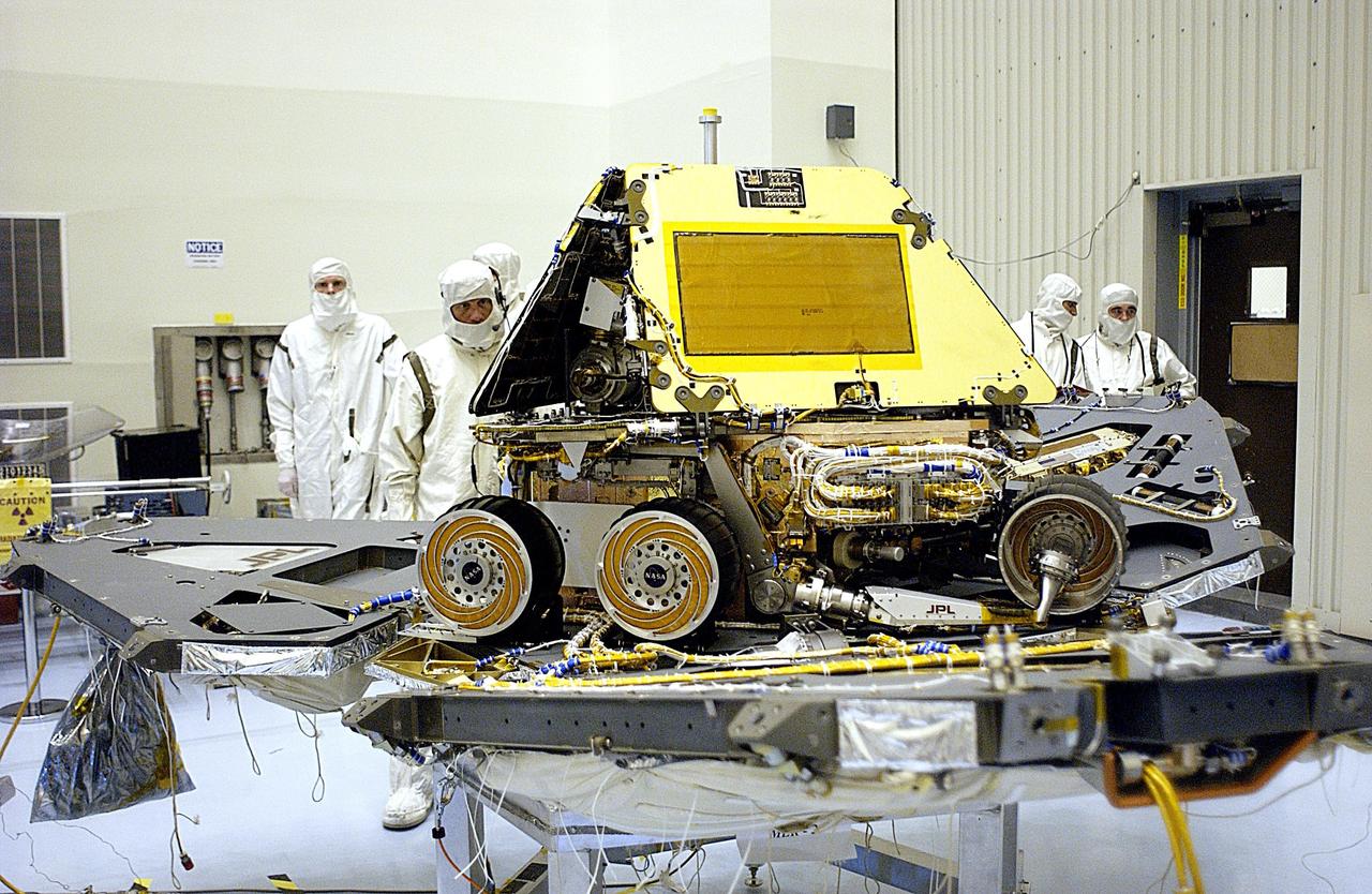
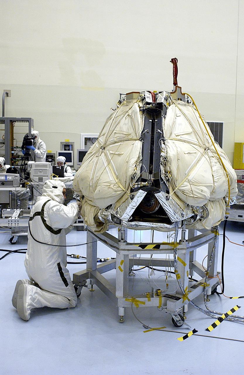
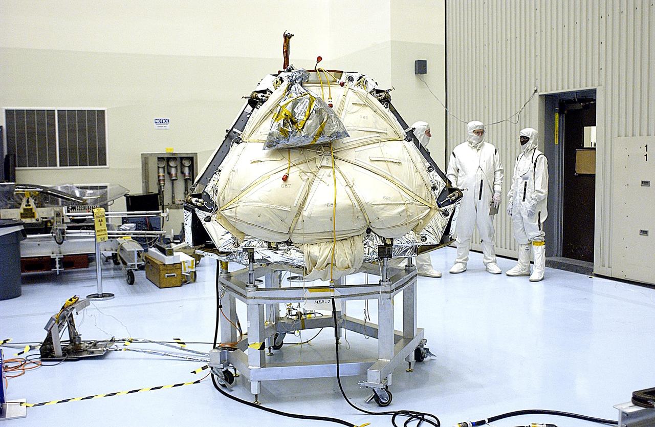
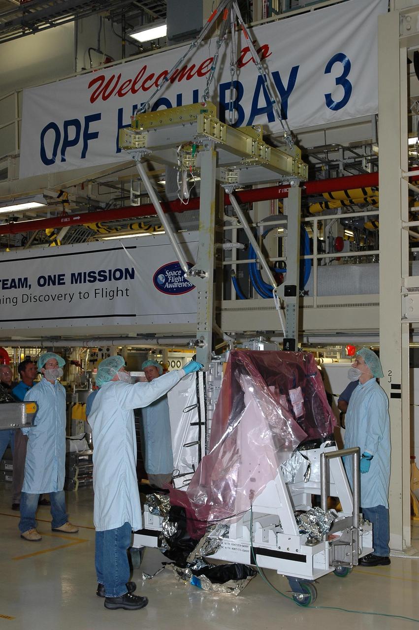
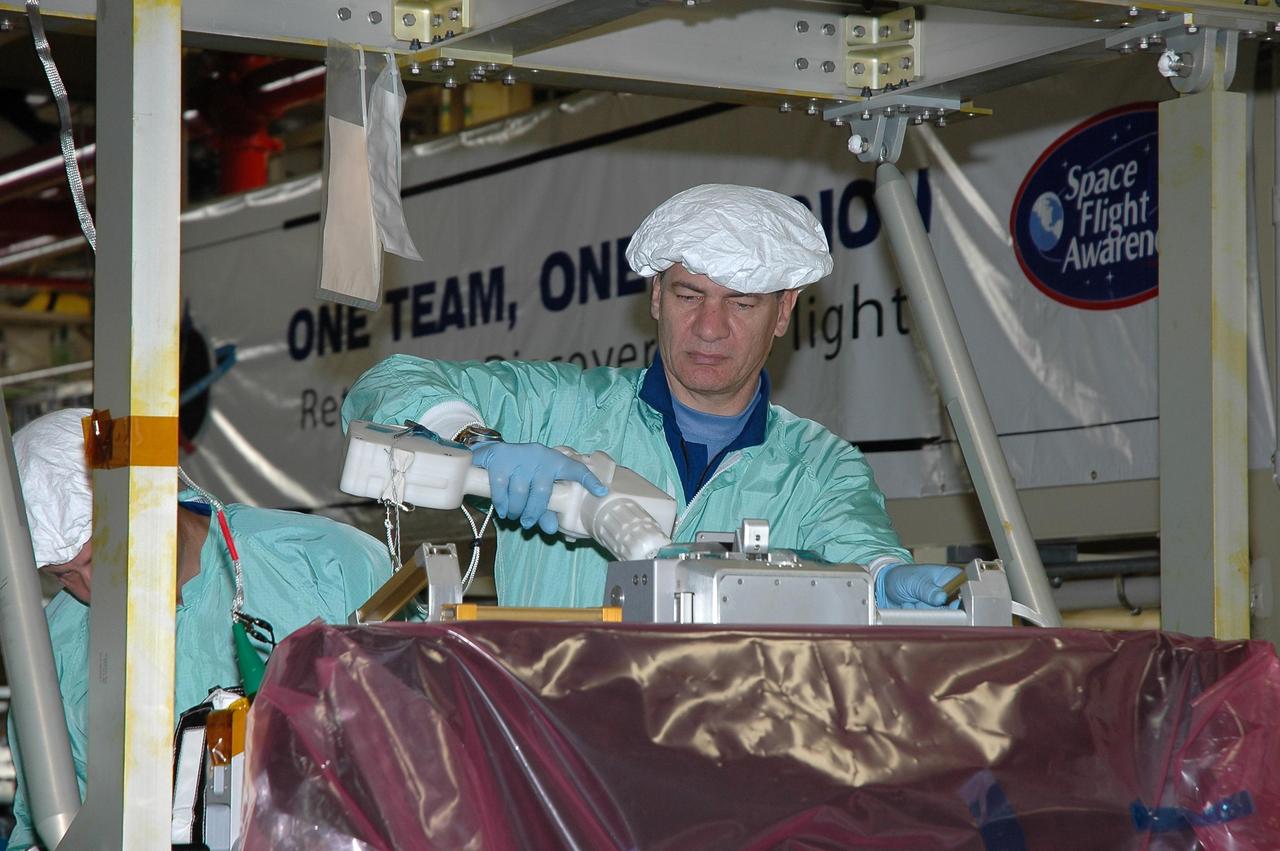
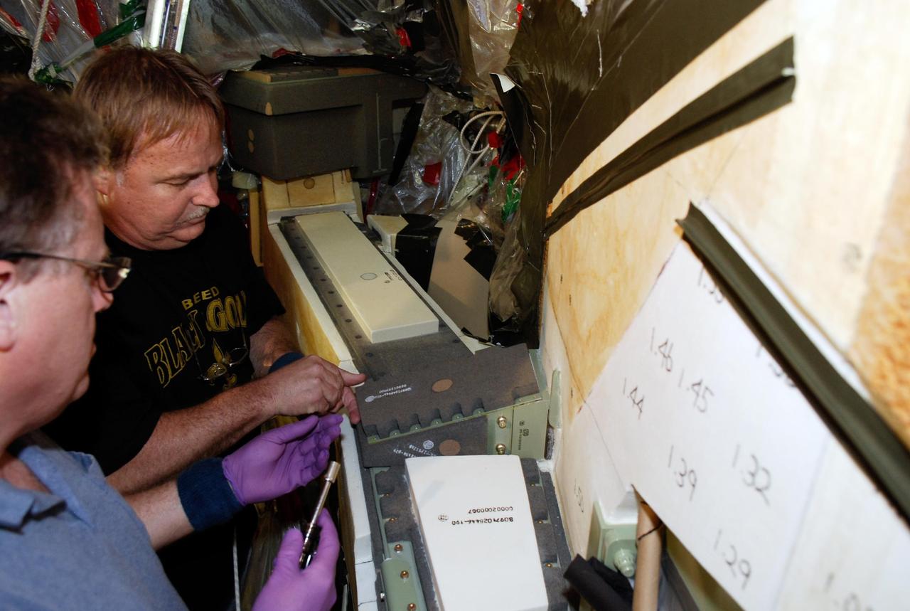
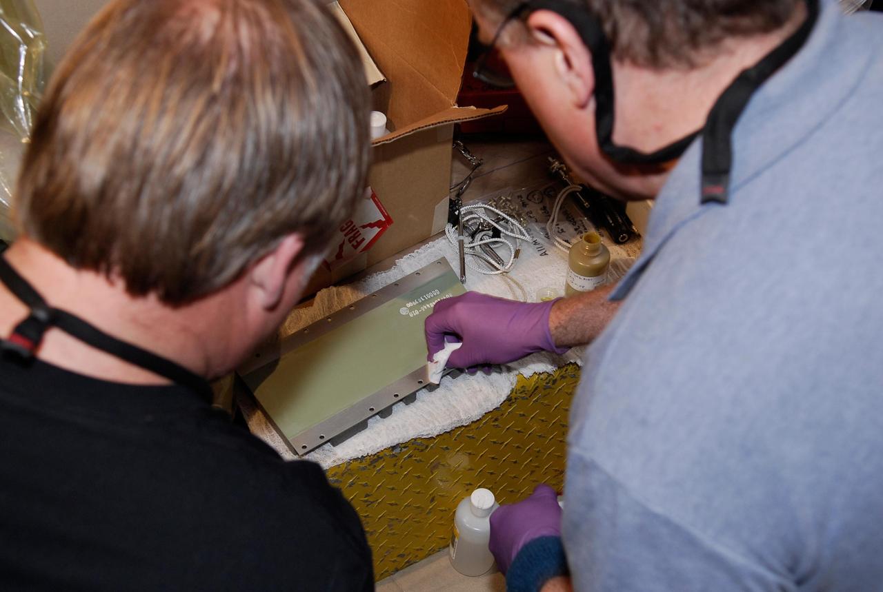
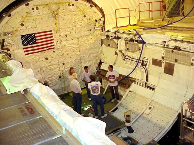
In the Payload Hazardous Servicing Facility, technicians remove one of the circuit boards on the Mars Exploration Rover 2 MER-2.
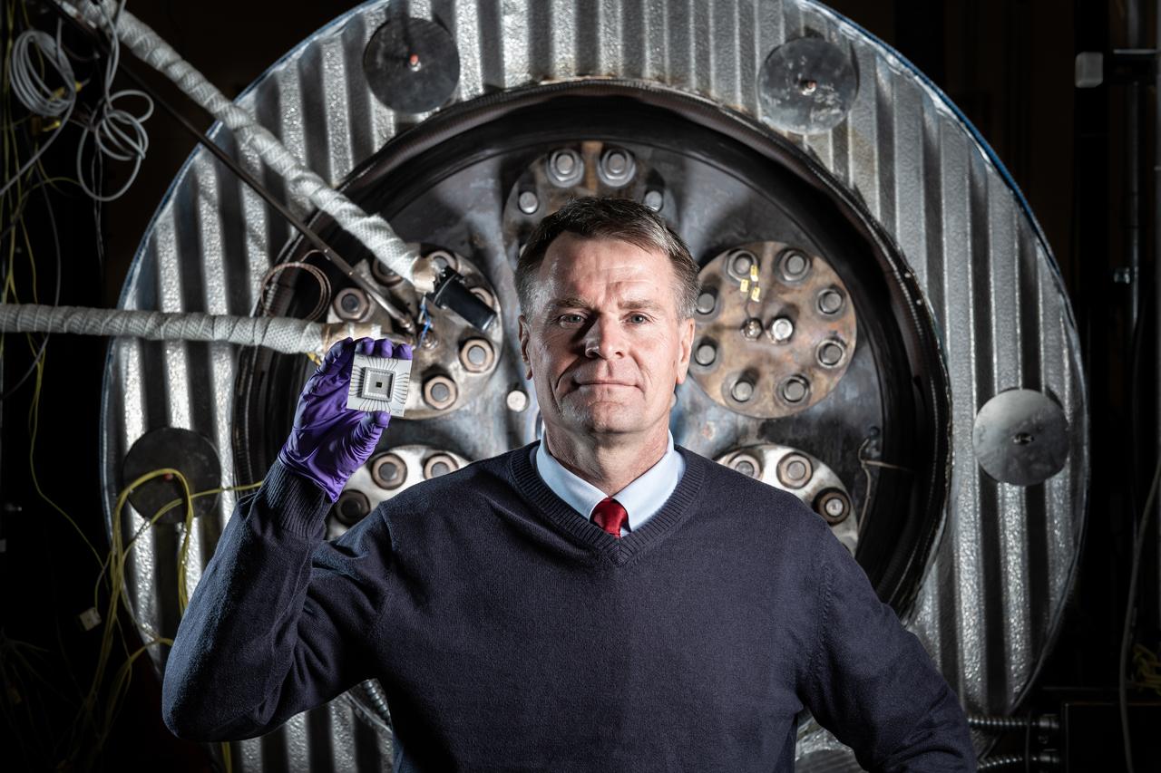
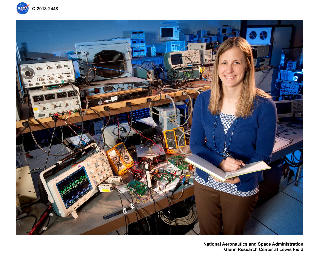
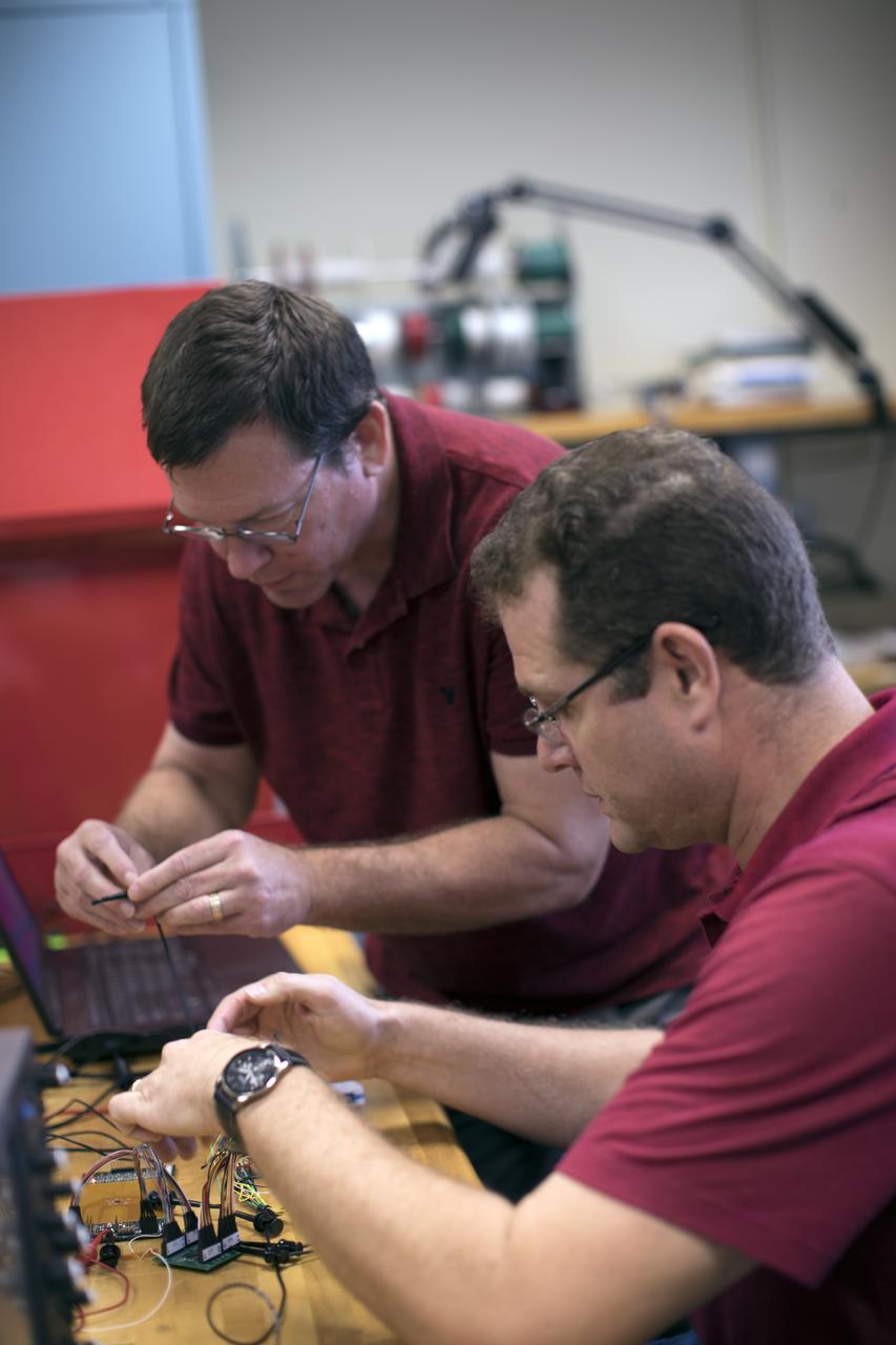
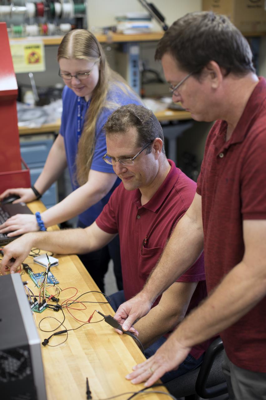
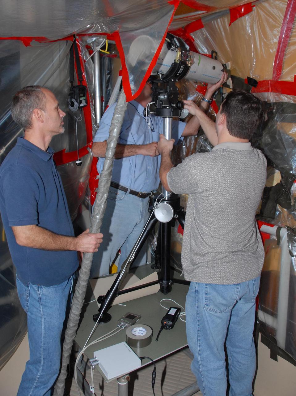
Phil Neudeck- Can Take the Heat When it comes to the heat of extreme environments like Venus, electronics can get fried within a few minutes of arrival. But NASA Researcher Phil Neudeck and his team have developed extremely durable silicon carbide semiconductor integrated circuits to survive those harsh conditions. After successfully testing the electronics in our high-pressure, high-temperature extreme environments chamber, there is now a path forward for Venus landers to survive and operate scientific experiments on the planet’s surface for longer durations.
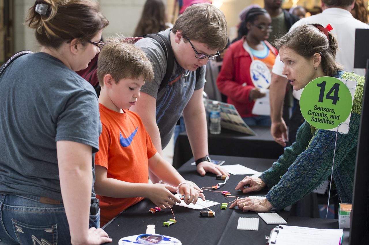
An attendee of NASA's Earth Day event conducts an experiment with circuits. The event took place at Union Station in Washington, DC on April 22, 2014. Photo Credit: (NASA/Aubrey Gemignani)
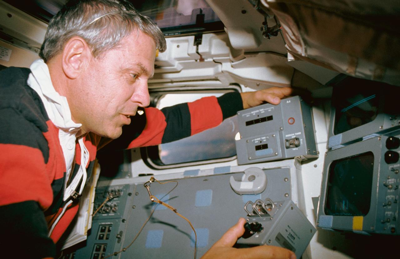
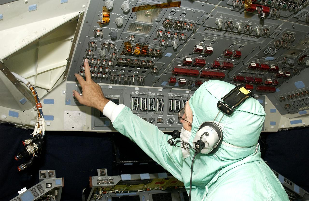
STS035-10-011 (2-10 Dec 1990) --- STS-35 Mission Specialist (MS) Robert A.R. Parker operates Astronomy Laboratory 1 (ASTRO-1) manual pointing controller (MPC) on the aft flight deck of Columbia, Orbiter Vehicle (OV) 102. Parker monitors a closed circuit television (CCTV) screen at the payload station as he uses the MPC to send data collection instructions to the ASTRO-1 instrument pointing system (IPS).
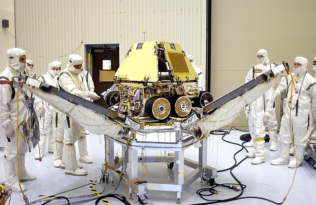
In the Payload Hazardous Servicing Facility, technicians reopen the lander petals of the Mars Exploration Rover 2 MER-2 to allow access to one of the spacecraft circuit boards.
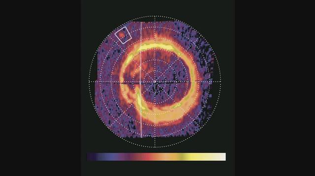
NASA Cassini spacecraft has spotted a glowing patch of ultraviolet light near Saturn north pole that marks the presence of an electrical circuit that connects Saturn with its moon Enceladus. Movie available at the Photojournal.
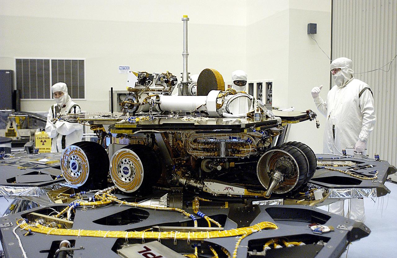
In the Payload Hazardous Servicing Facility, the lander petals of the Mars Exploration Rover 2 MER-2 have been reopened and its solar panels deployed to allow technicians access to the spacecraft to remove one of its circuit boards.
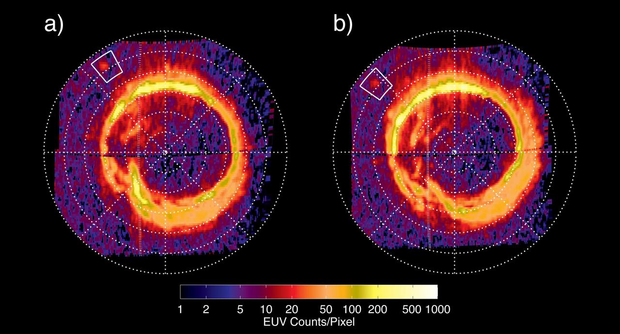
NASA Cassini spacecraft has spotted a glowing patch of ultraviolet light near Saturn north pole that marks the presence of an electrical circuit that connects Saturn with its moon Enceladus.
EXPRESS PPU POWER PROPULSION UNIT 160 CIRCUIT BOARDS FOR POWER UNIT OF ION THRUSTER
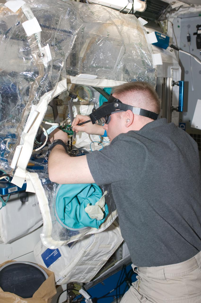
ISS018-E-033818 (19 Feb. 2009) --- Astronaut Michael Fincke, Expedition 18 commander, removes, cleans and replaces electronic test components on a single test card using Component Repair Equipment (CRE-1) hardware in a portable glovebox facility in the Harmony node of the International Space Station. Fincke unsoldered 1 1/2 components from an integrated circuit board and re-soldered new components including an integrated circuit chip.
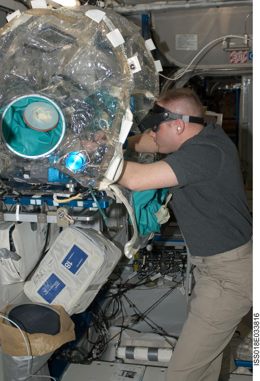
ISS018-E-033816 (19 Feb. 2009) --- Astronaut Michael Fincke, Expedition 18 commander, removes, cleans and replaces electronic test components on a single test card using Component Repair Equipment (CRE-1) hardware in a portable glovebox facility in the Harmony node of the International Space Station. Fincke unsoldered 1 1/2 components from an integrated circuit board and re-soldered new components including an integrated circuit chip.
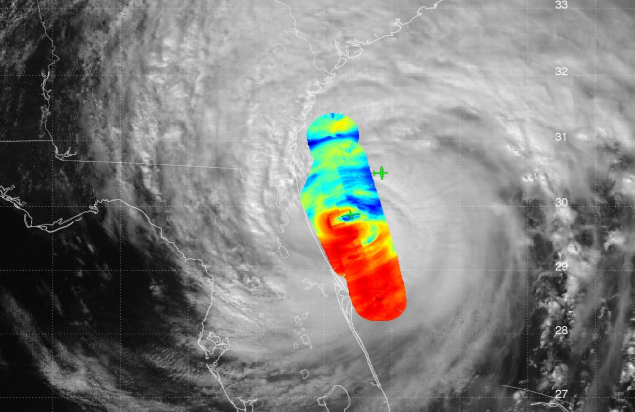
JPL's High-Altitude Monolithic Microwave Integrated Circuit Sounding Radiometer (HAMSR) instrument captured this look inside Hurricane Matthew's spiral clouds on Oct. 7, 2016, flying on a NASA Global Hawk unmanned aircraft. Red colors show cloud bands without precipitation; blues show rain bands. http://photojournal.jpl.nasa.gov/catalog/PIA21093

NASA's Administrator, Charles Bolden, conducts an experiment using circuits at NASA's Earth Day event. The event took place at Union Station in Washington, DC on April 22, 2014. Photo Credit: (NASA/Aubrey Gemignani)
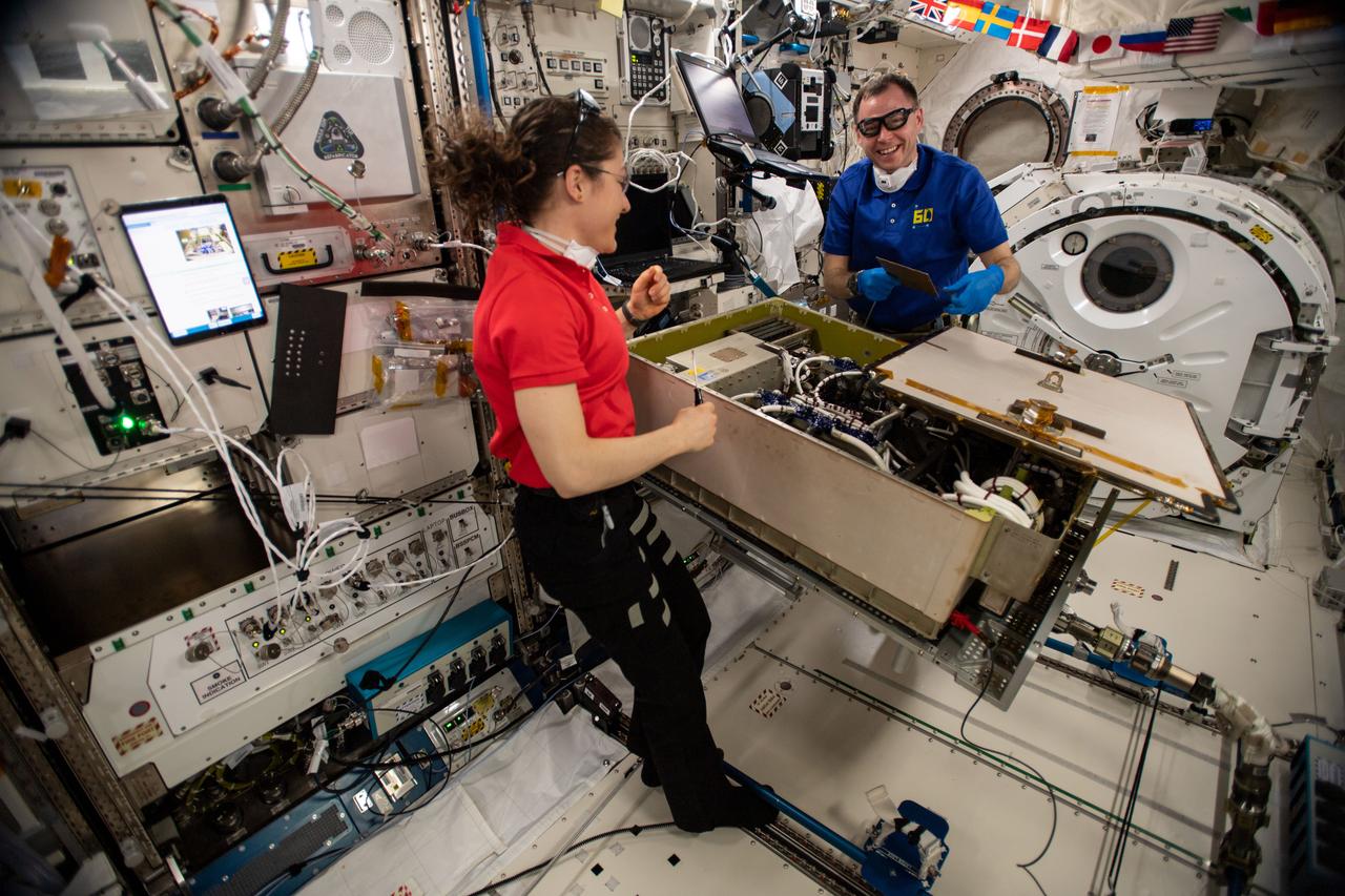
Expedition 60 flight engineers Christina Koch and Nick Hague of NASA work together on the Main Bus Switching Unit aboard the space station to replace a failed circuit card before performing a test to ensure its functionality.
Environmental Portrait, Electrical Power Systems Employee, hardware for the High Power 300-Volt Power Processing Unit (PPU). The Printed Circuit Boards (PCBs) are the Discharge Module Inverter and the Pulse Width Modulation (PWM) Controller
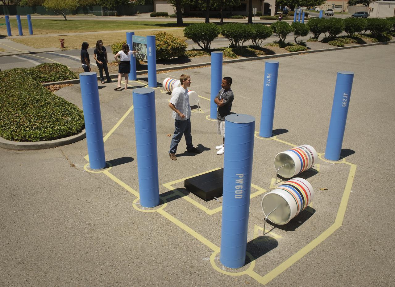
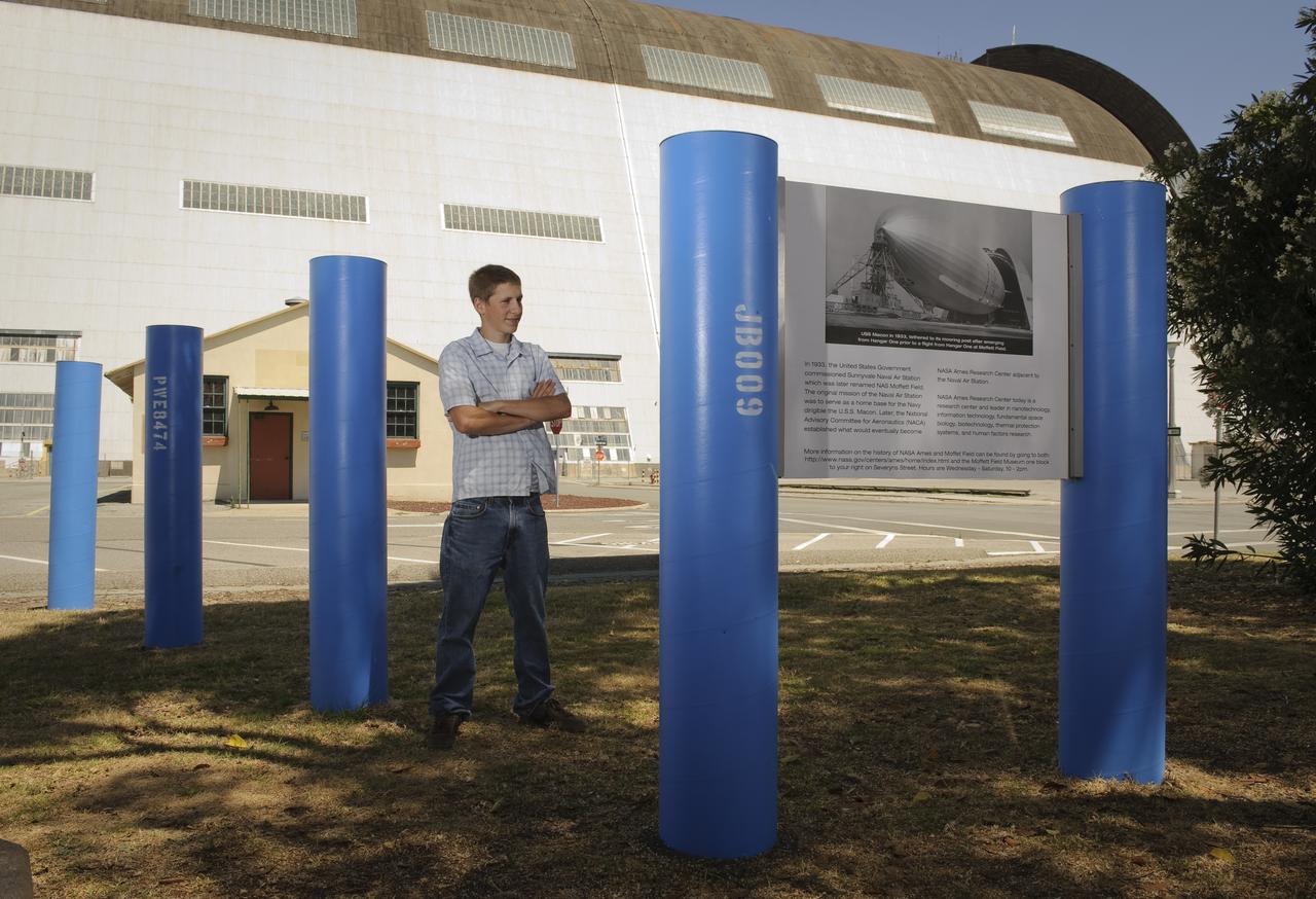
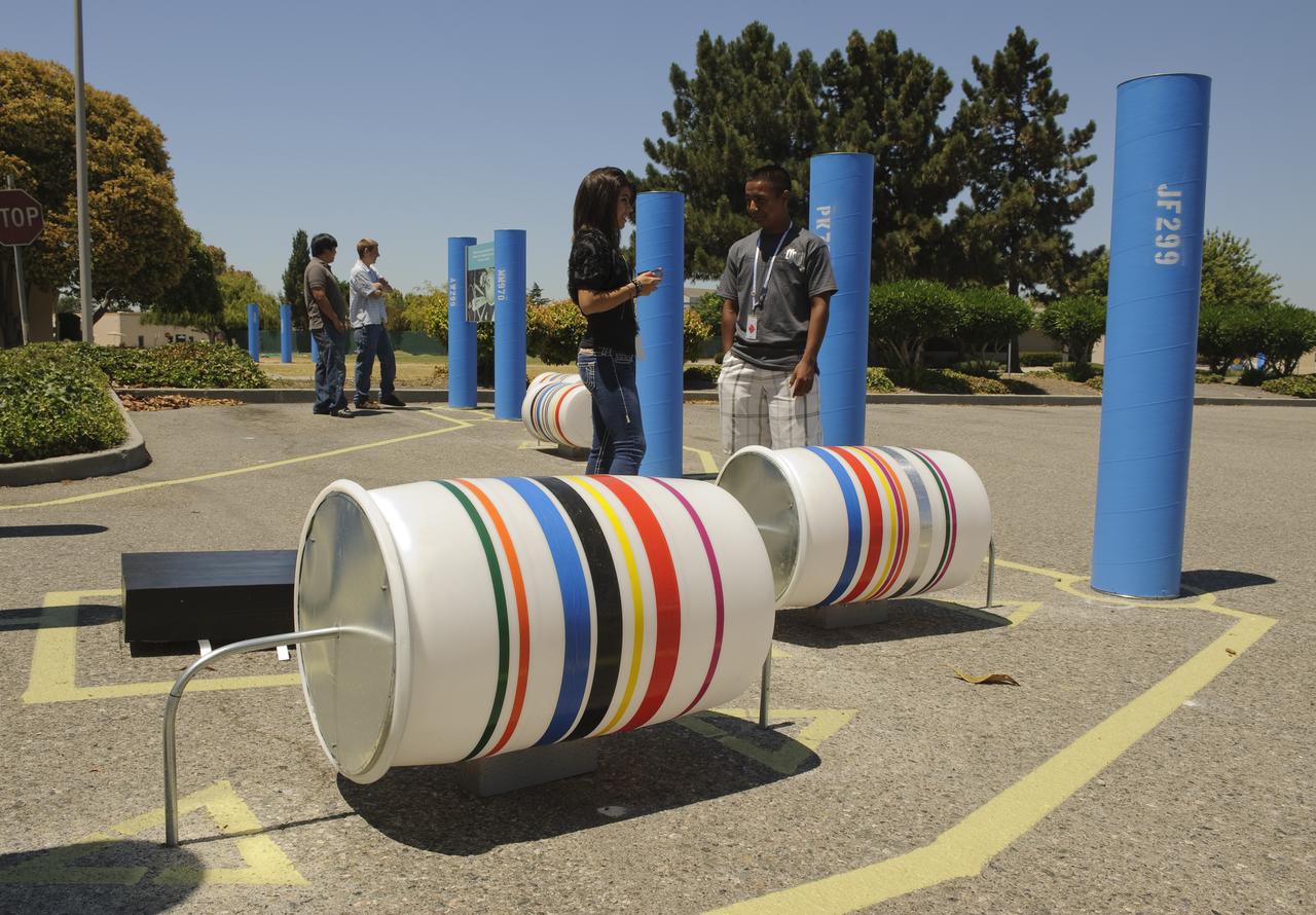
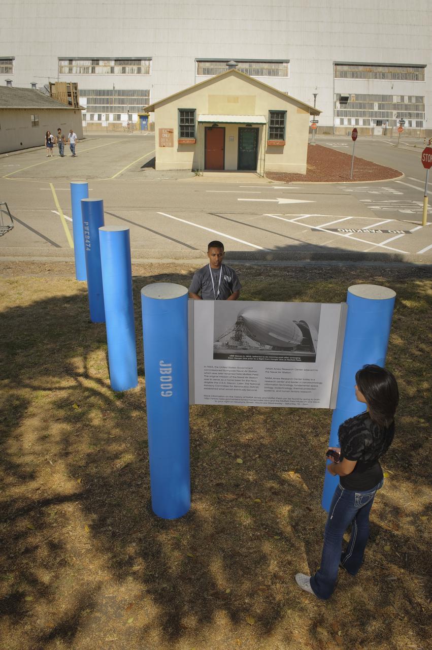
ISU Line of Questions (designed by Planners Collaborative, Inc./depicts a circuit board.) a visual for summer students to find their way around NASA Research Park and to the different venues
ISU Line of Questions (designed by Planners Collaborative, Inc./depicts a circuit board.) a visual for summer students to find their way around NASA Research Park and to the different venues
ISU Line of Questions (designed by Planners Collaborative, Inc./depicts a circuit board.) a visual for summer students to find their way around NASA Research Park and to the different venues
ISU Line of Questions (designed by Planners Collaborative, Inc./depicts a circuit board.) a visual for summer students to find their way around NASA Research Park and to the different venues
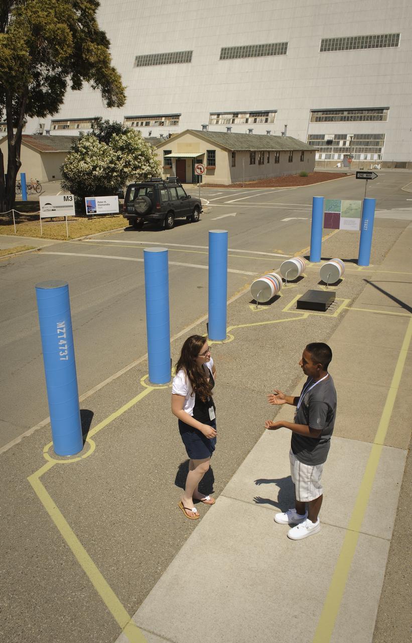
ISU Line of Questions (designed by Planners Collaborative, Inc./depicts a circuit board.) a visual for summer students to find their way around NASA Research Park and to the different venues
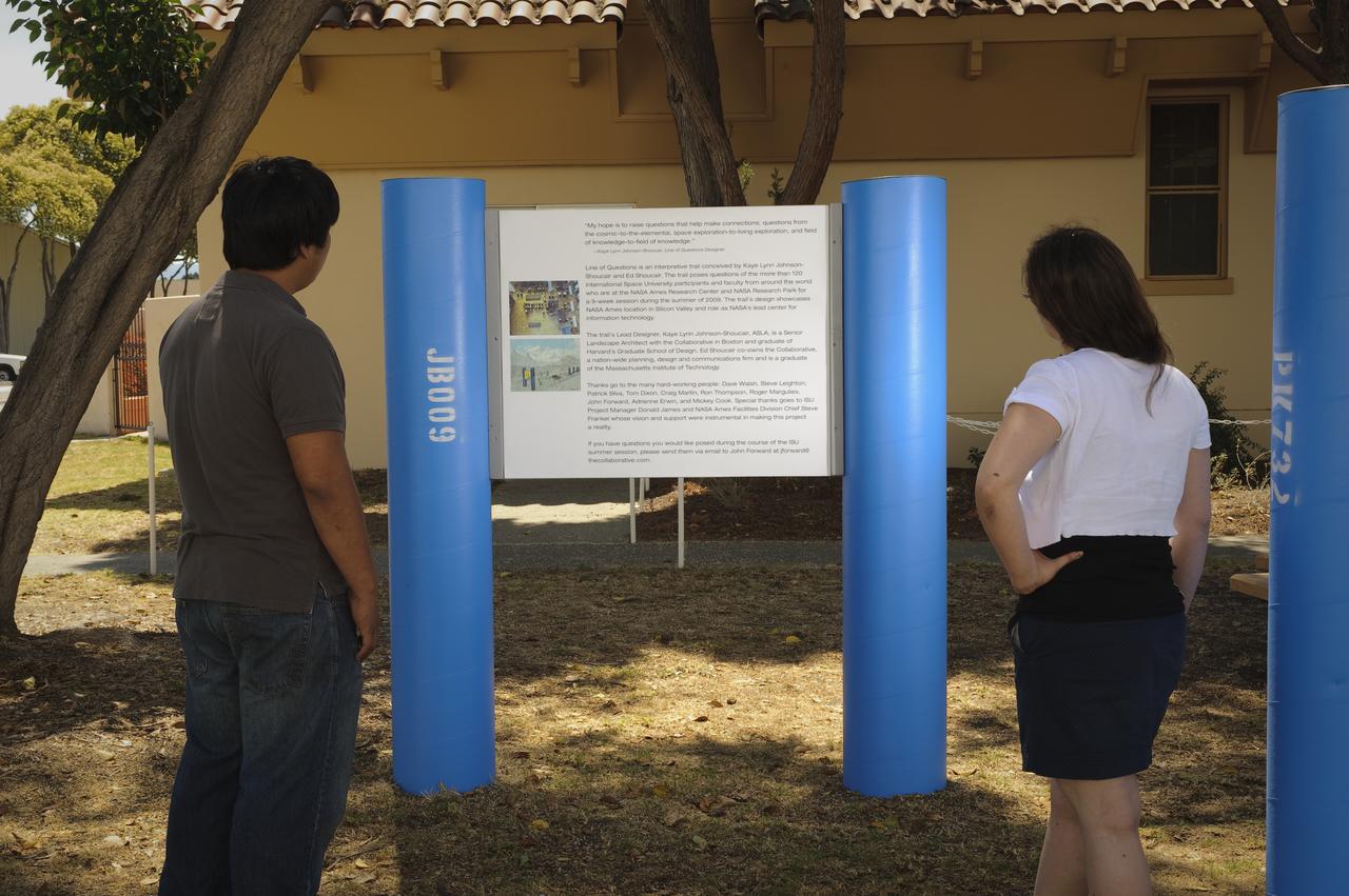
ISU Line of Questions (designed by Planners Collaborative, Inc./depicts a circuit board.) a visual for summer students to find their way around NASA Research Park and to the different venues
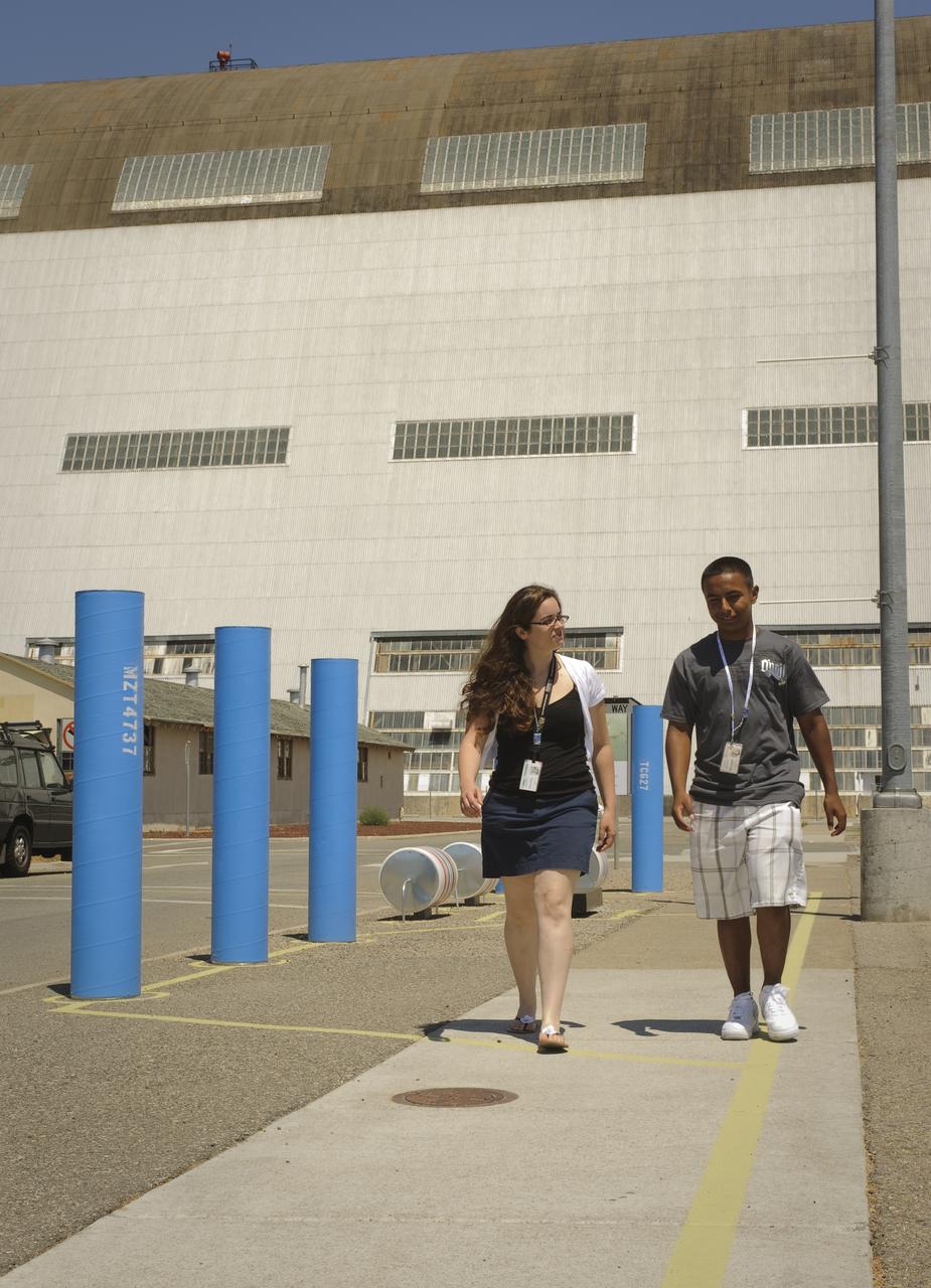
ISU Line of Questions (designed by Planners Collaborative, Inc./depicts a circuit board.) a visual for summer students to find their way around NASA Research Park and to the different venues
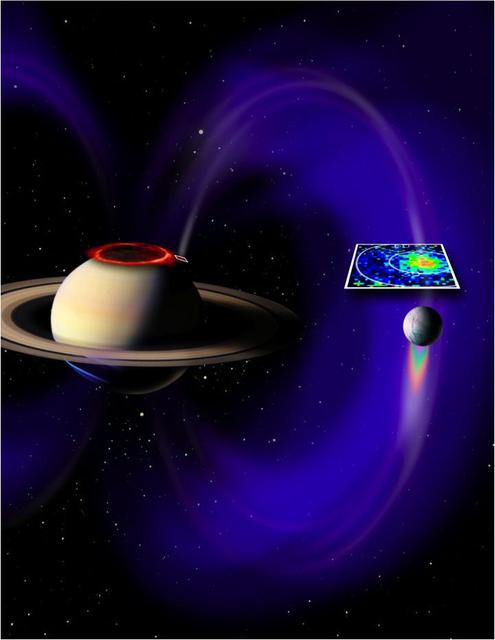
This artist concept based on data from NASA Cassini spacecraft, shows a glowing patch of ultraviolet light near Saturn north pole that occurs at the footprint of the magnetic connection between Saturn and its moon Enceladus.
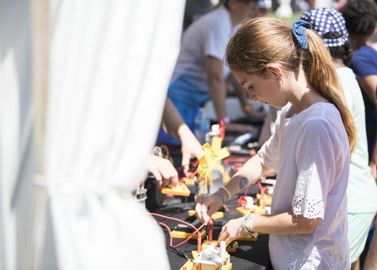
A visitor learns about circuits at the Apollo 11 50th Anniversary celebration on the National Mall, Friday, July 19, 2019 in Washington. Apollo 11 was the first mission to land astronauts on the Moon and launched on July 16, 1969 with astronauts Neil Armstrong, Michael Collins, and Buzz Aldrin. Photo Credit: (NASA/Aubrey Gemignani)
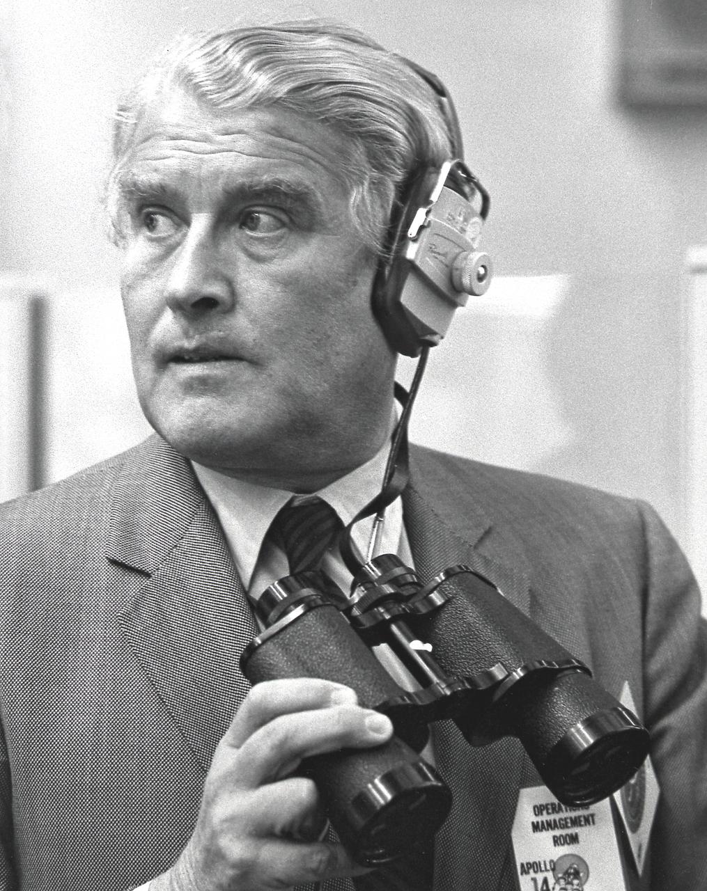
Dr. Wernher von Braun, NASA Deputy Associate Administrator for Future Programs, uses binoculars to monitor data on the closed-circuit TV screen in the Firing Room of the Launch Control Center at Kennedy Space Center (KSC) during the final preparation for the Apollo 14 launch.
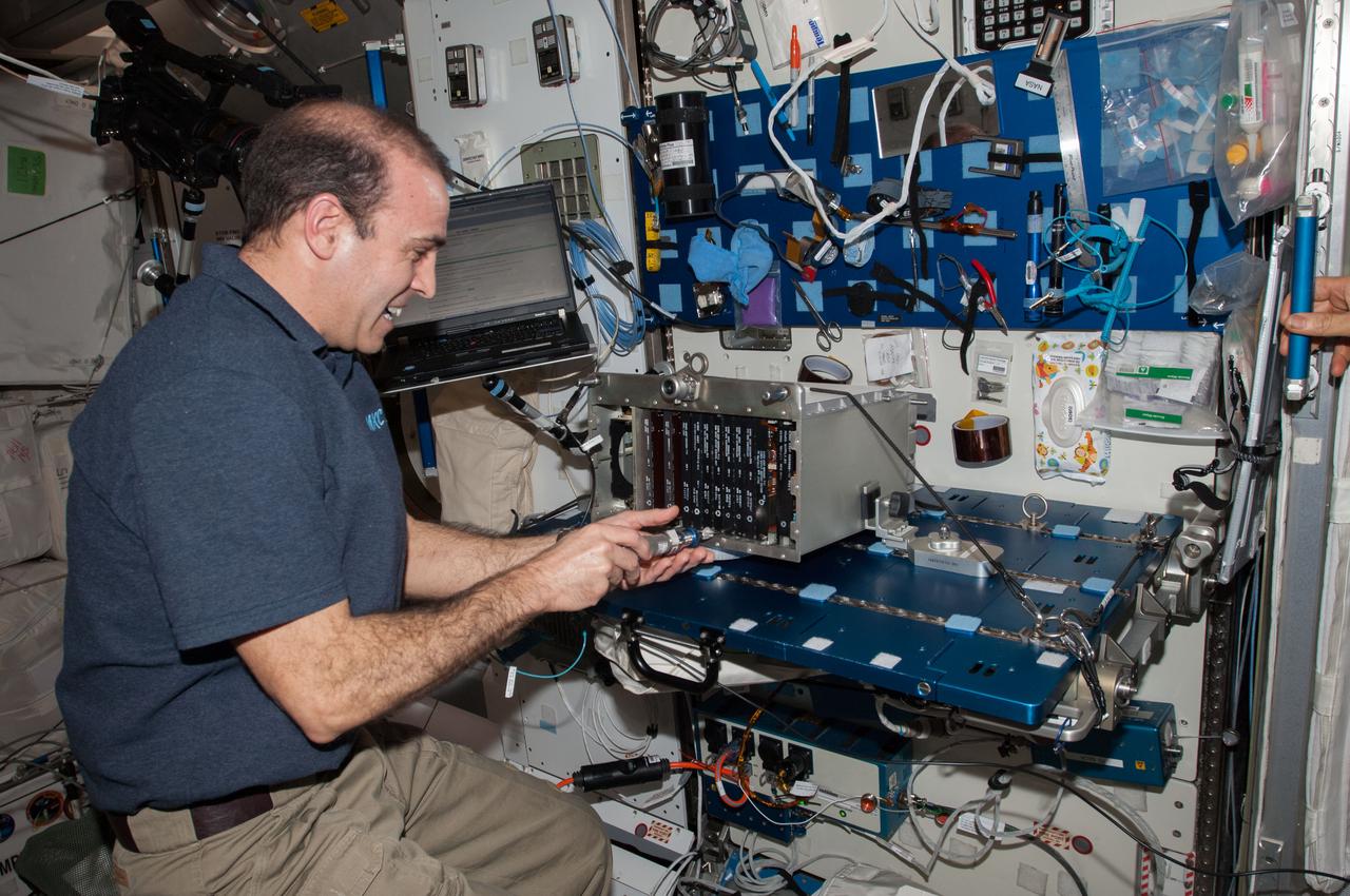
ISS039-E-013244 (18 April 2014) --- NASA astronaut Rick Mastracchio, Expeditionn 39 flight engineer, replaces the Enhanced Input/Output Control Unit Circuit Card of the spare External Multiplexer/Demultiplexer (MDM), in preparation for an upcoming spacewalk. He will be joined by fellow NASA astronaut and Flight Engineer Steve Swanson on the spacewalk.
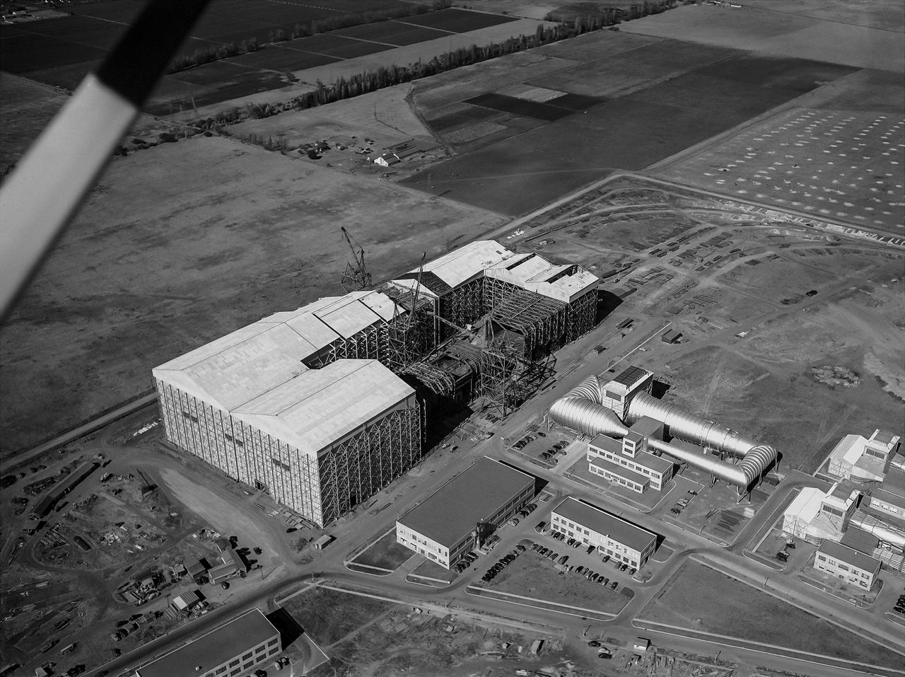
Aerial view looking North West of the nearly completed 40 x 80 foot wind tunnel. Drive and test section exposed. The facility covered 8 acres, and the air circuit was just over 1/2 mile long (2700 feet).
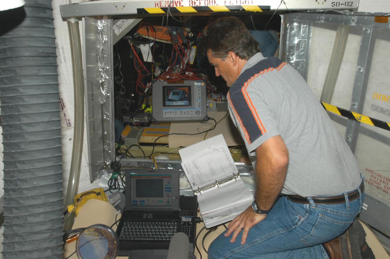
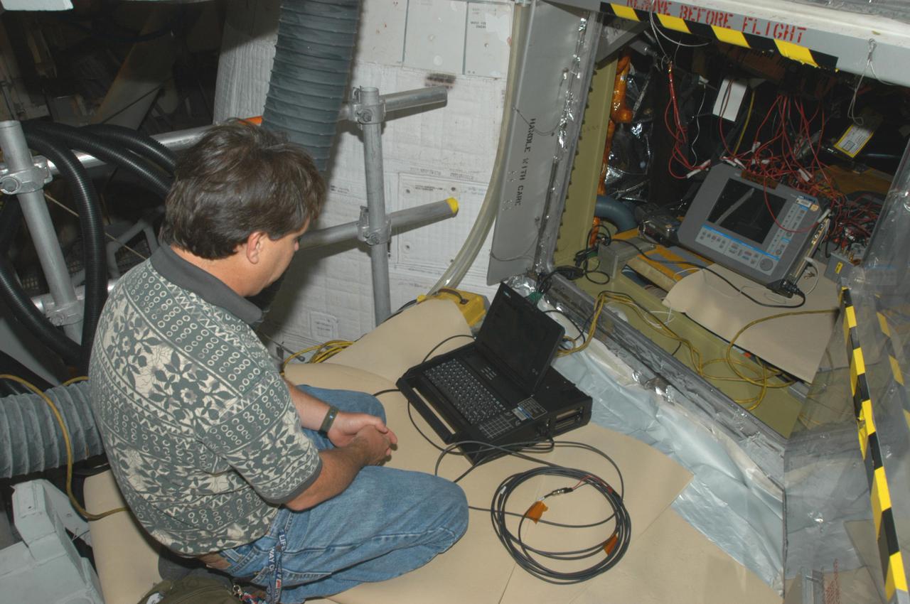
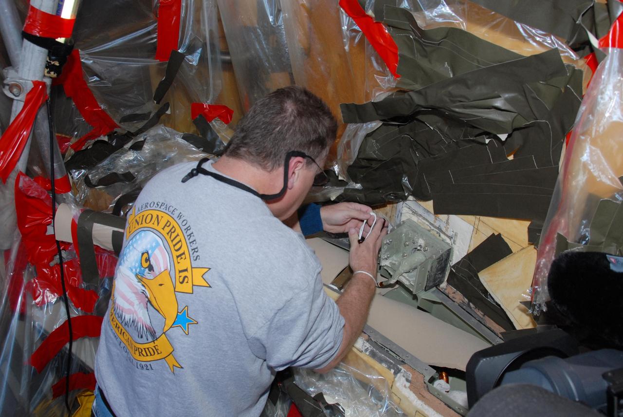
KENNEDY SPACE CENTER, FLA. - Bill Drier, NASA, is conducting electromagnetic interference and ground resistance testing on wiring in the aft engine compartment on Space Shuttle Discovery using various test equipment, such as current probes, amp meters, digital volt meters, breakout boxes, Nicollet recorders, oscilloscopes and time domain reflectometers. Other testing will evaluate wiring runs and connections for any reactions under semi-cryogenic conditions.Other testing will evaluate wiring runs and connections in the aft engine of Space Shuttle Discovery for any reactions under semi-cryogenic conditions, using a Nicolet data recorder. Engineering teams have been working through a troubleshooting plan to address an issue with a liquid hydrogen low-level fuel sensor circuit. The sensor circuit failed a routine prelaunch check during the countdown July 13, delaying Discovery’s first launch attempt on Return to Flight mission STS-114.
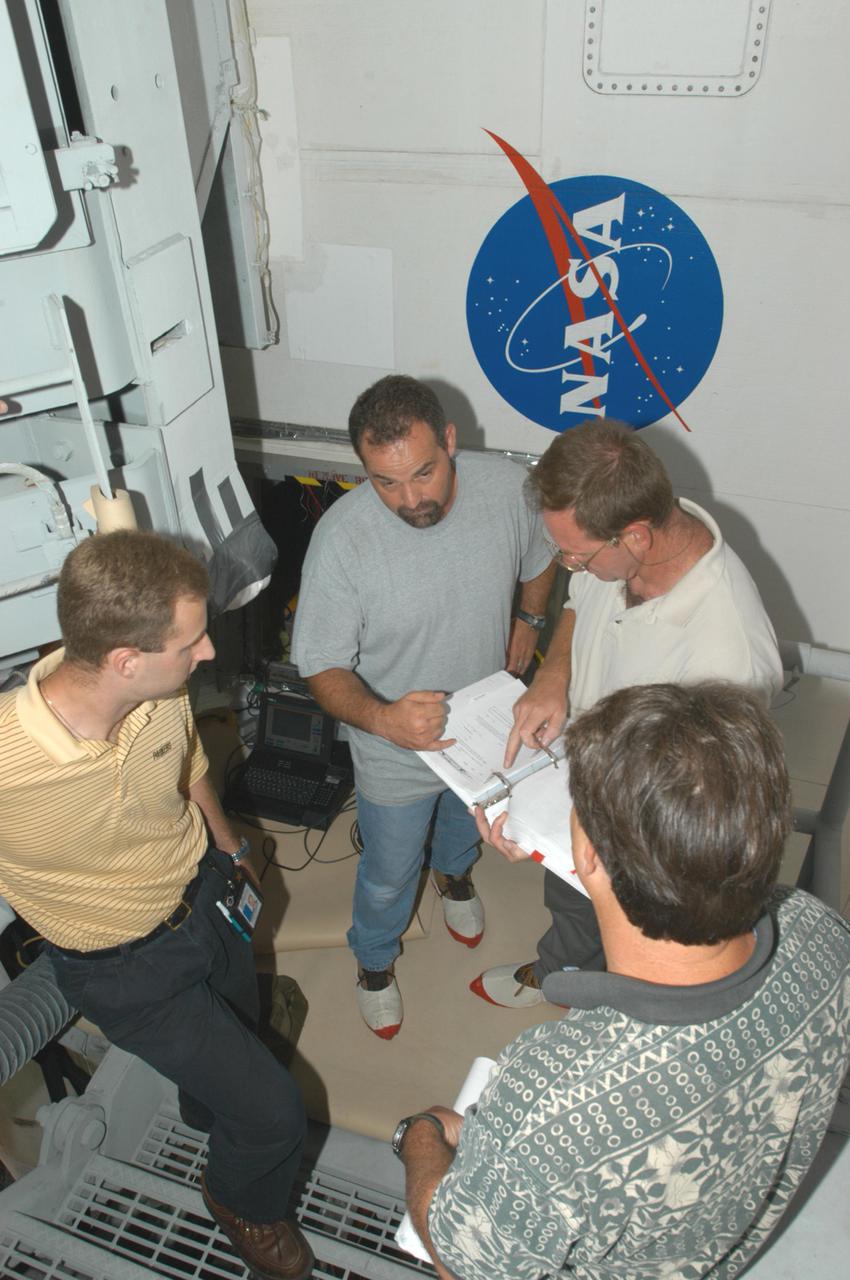
KENNEDY SPACE CENTER, FLA. - After conducting electromagnetic interference and ground resistance testing on wiring in the aft engine compartment on Space Shuttle Discovery using various test equipment, such as current probes, amp meters, digital volt meters, breakout boxes, Nicollet recorders, oscilloscopes and time domain reflectometers, Aaron Sherman (left), Jack Colella (center) and Jeff Huet (lower right), all with United Space Alliance, and John Kennedy, NASA, review data. Engineering teams have been working through a troubleshooting plan to address an issue with a liquid hydrogen low-level fuel sensor circuit. The sensor circuit failed a routine prelaunch check during the countdown July 13, delaying Discovery’s first launch attempt on Return to Flight mission STS-114.
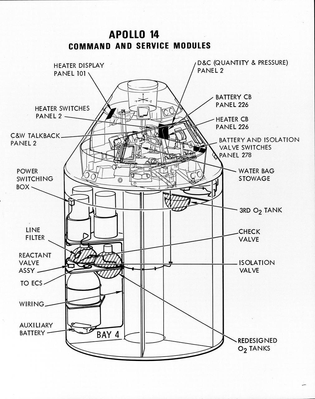
S71-16823 (January 1971) --- A line drawing illustrating a cutaway view of the Apollo 14 Command and Service Modules, showing the engineering changes in the CSM which were recommended by the Apollo 13 Review Board. (The Apollo 13 abort was caused by a short circuit and wiring overheating in one of the SM cryogenic oxygen tanks.) The major changes to the Apollo 14 CSM include adding a third cryogenic oxygen tank installed in a heretofore empty bay (in sector one) of the SM, addition of an auxiliary battery in the SM as a backup in case of fuel cell failure, and removal of destratification fans in the cryogenic oxygen tanks and removal of thermostat switches from the oxygen tank heater circuits. Provision for stowage of an emergency five-gallon supply of drinking water has been added to the CM.
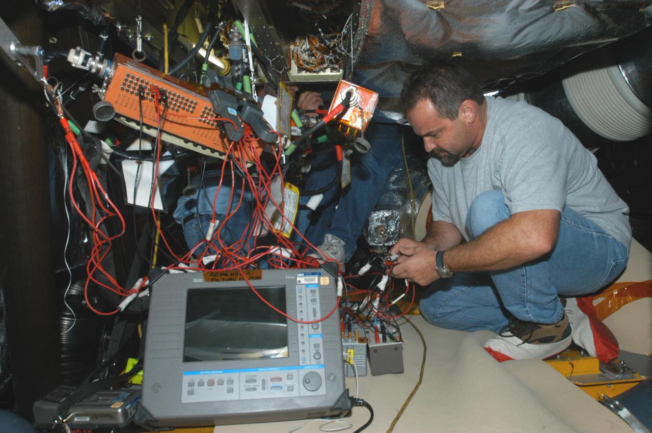
KENNEDY SPACE CENTER, FLA. - Jack Colella, with United Space Alliance, is conducting electromagnetic interference and ground resistance testing on wiring in the aft engine compartment on Space Shuttle Discovery using various test equipment, such as current probes, amp meters, digital volt meters, breakout boxes, Nicollet recorders, oscilloscopes and time domain reflectometers. Other testing will evaluate wiring runs and connections for any reactions under semi-cryogenic conditions. Engineering teams have been working through a troubleshooting plan to address an issue with a liquid hydrogen low-level fuel sensor circuit. The sensor circuit failed a routine prelaunch check during the countdown July 13, delaying Discovery’s first launch attempt on Return to Flight mission STS-114.
KENNEDY SPACE CENTER, FLA. - Jeff Huet, with United Space Alliance, is conducting electromagnetic interference and ground resistance testing on wiring in the aft engine compartment on Space Shuttle Discovery using various test equipment, such as current probes, amp meters, digital volt meters, breakout boxes, Nicollet recorders, oscilloscopes and time domain reflectometers. Other testing will evaluate wiring runs and connections for any reactions under semi-cryogenic conditions. Other testing will evaluate wiring runs and connections for any reactions under semi-cryogenic conditions, using a Nicolet data recorder. Engineering teams have been working through a troubleshooting plan to address an issue with a liquid hydrogen low-level fuel sensor circuit. The sensor circuit failed a routine prelaunch check during the countdown July 13, delaying Discovery’s first launch attempt on Return to Flight mission STS-114.

KENNEDY SPACE CENTER, FLA. - During power-up of the orbiter Discovery in the Orbiter Processing Facility, a technician (left) looks at the circuit breaker lights in the cabin. Discovery has been undergoing Orbiter Major Modifications in the past year, ranging from wiring, control panels and black boxes to gaseous and fluid systems tubing and components. These systems were deserviced, disassembled, inspected, modified, reassembled, checked out and reserviced, as were most other systems onboard. The work includes the installation of the Multifunction Electronic Display Subsystem (MEDS) - a state-of-the-art “glass cockpit.”

KENNEDY SPACE CENTER, FLA. -- In the Payload Hazardous Servicing Facility, technicians reopen the lander petals of the Mars Exploration Rover 2 (MER-2) to allow access to one of the spacecraft's circuit boards. A concern arose during prelaunch testing regarding how the spacecraft interprets signals sent from its main computer to peripherals in the cruise stage, lander and small deep space transponder. The MER Mission consists of two identical rovers set to launch in June 2003. The problem will be fixed on both rovers.
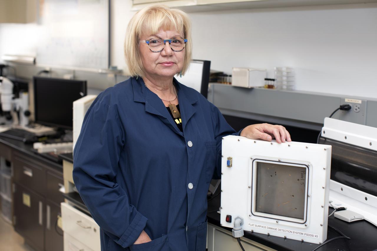
Martha Williams, who leads the team inventing the Flexible Damage Detection System, stands in a laboratory with a prototype at NASA's Kennedy Space Center in Florida. The system uses circuits printed on thin thermal film and specialized software. The system is designed to show where damage to a surface occurs and how severe it may be. It could offer astronauts a real-time update on their spacecraft's condition during a mission without requiring a spacewalk.
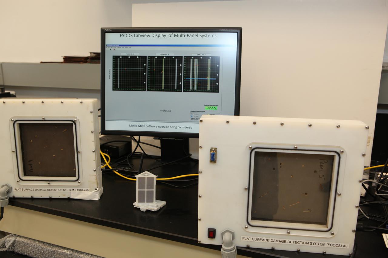
The complete prototype Flexible Damage Detection System stands in a laboratory at NASA's Kennedy Space Center in Florida. The system uses circuits printed on thin thermal film and specialized software. The system is designed to show where damage to a surface occurs and how severe it may be. It could offer astronauts a real-time update on their spacecraft's condition during a mission without requiring a spacewalk. Photo credit: NASA/Dimitri Gerondidakis
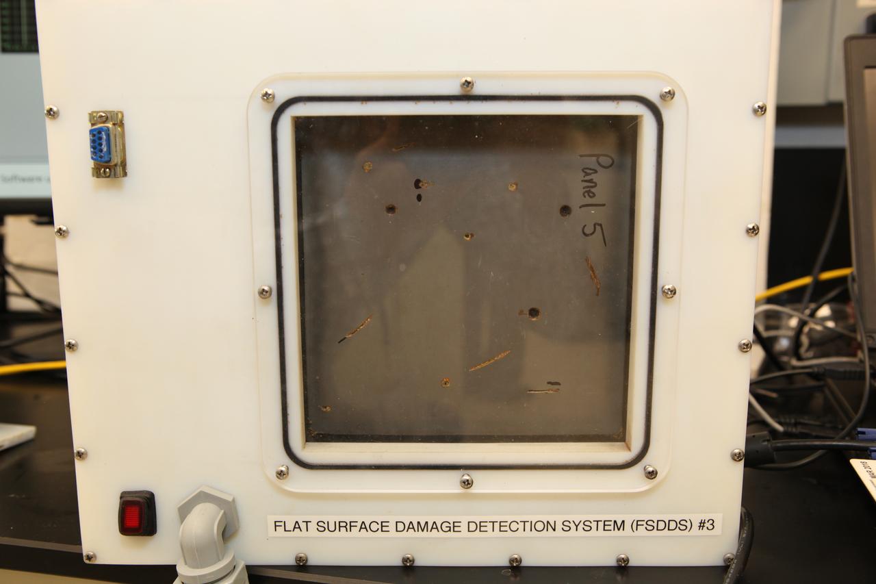
The prototype Flexible Damage Detection System stands in a laboratory at NASA's Kennedy Space Center in Florida. The system uses circuits printed on thin thermal film and specialized software. The system is designed to show where damage to a surface occurs and how severe it may be. It could offer astronauts a real-time update on their spacecraft's condition during a mission without requiring a spacewalk.
During power-up of the orbiter Discovery in the Orbiter Processing Facility, a technician moves a circuit reset on the cockpit console. Discovery has been undergoing Orbiter Major Modifications in the past year, ranging from wiring, control panels and black boxes to gaseous and fluid systems tubing and components. These systems were deserviced, disassembled, inspected, modified, reassembled, checked out and reserviced, as were most other systems onboard. The work includes the installation of the Multifunction Electronic Display Subsystem (MEDS) - a state-of-the-art “glass cockpit.”
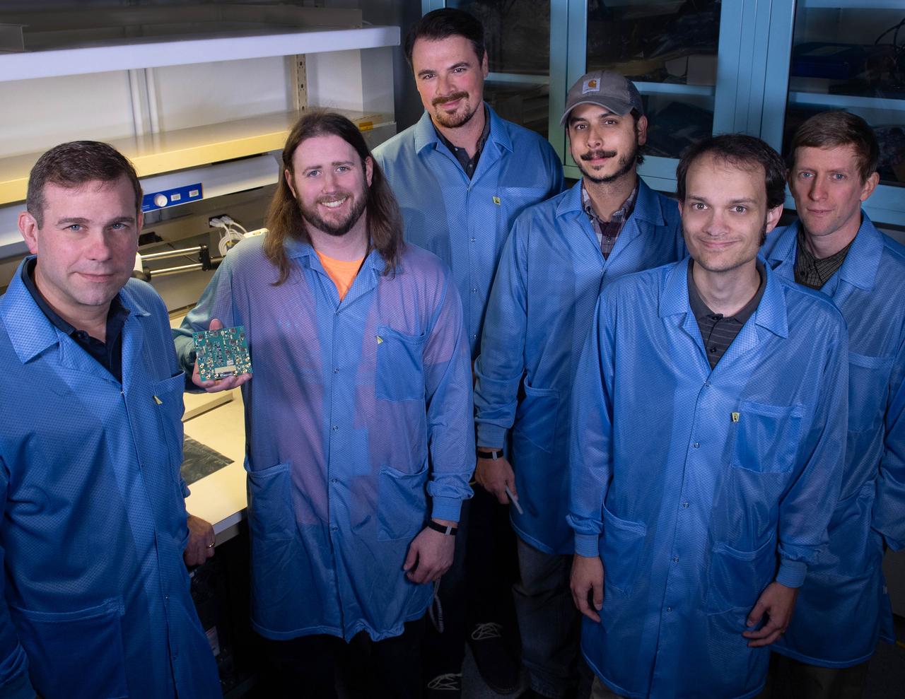
Several Goddard technologists are involved in a new CubeSat technology-demonstration mission called SNoOPI, which employs a novel remote-sensing technique for measuring soil-moisture levels. From left to right: Jeffrey Piepmeier, Chase Kielbasa, who is holding a first-generation prototype circuit board for the SNoOPI instrument, Joseph Knuble, Manuel Vega, Michael Coon, and Derek Hudson.
KENNEDY SPACE CENTER, FLA. -- In the Payload Hazardous Servicing Facility, technicians reopen the lander petals of the Mars Exploration Rover 2 (MER-2) to allow access to one of the spacecraft's circuit boards. A concern arose during prelaunch testing regarding how the spacecraft interprets signals sent from its main computer to peripherals in the cruise stage, lander and small deep space transponder. The MER Mission consists of two identical rovers set to launch in June 2003. The problem will be fixed on both rovers.
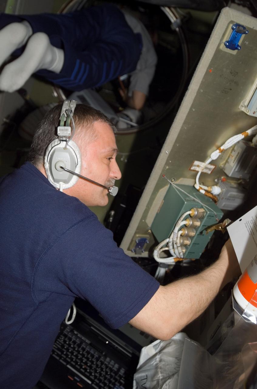
ISS015-E-17726 (6 July 2007) --- Cosmonaut Fyodor N. Yurchikhin, Expedition 15 commander representing Russia's Federal Space Agency, checks measurements of pin resistance on connectors de-mated from a command processing unit in the service module central computer-2 (SMCC-2) control circuit, which is located in the Zvezda Service Module of the International Space Station.
KENNEDY SPACE CENTER, FLA. -- On Launch Pad 39A, technicians overlook wires and monitoring equipment that will be used to validate the circuit on the test wiring from the electrical harness in space shuttle Atlantis' aft main engine compartment connected with the engine cut-off system. The test wiring leads from the tail mast on the mobile launcher platform to the interior where the Time Domain Reflectometry, or TDR, test equipment will be located to test the sensor system. Photo credit: NASA/Kim Shiflett
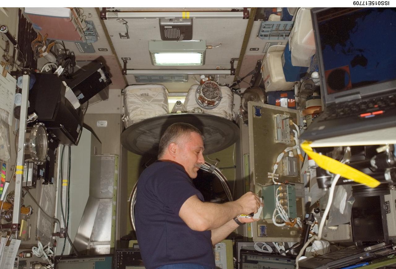
ISS015-E-17709 (6 July 2007) --- Cosmonaut Fyodor N. Yurchikhin, Expedition 15 commander representing Russia's Federal Space Agency, checks measurements of pin resistance on connectors de-mated from a command processing unit in the service module central computer-2 (SMCC-2) control circuit, which is located in the Zvezda Service Module of the International Space Station.
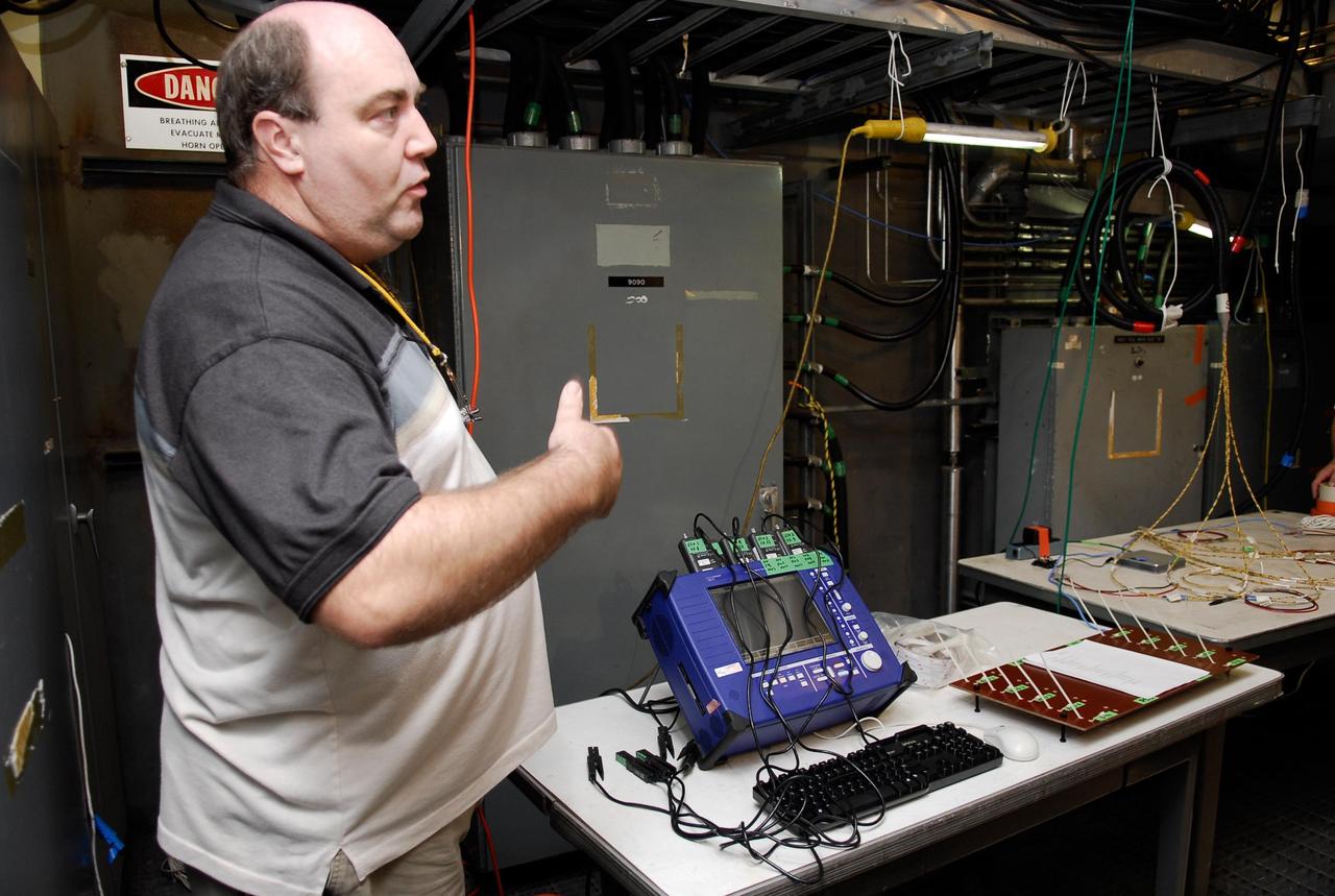
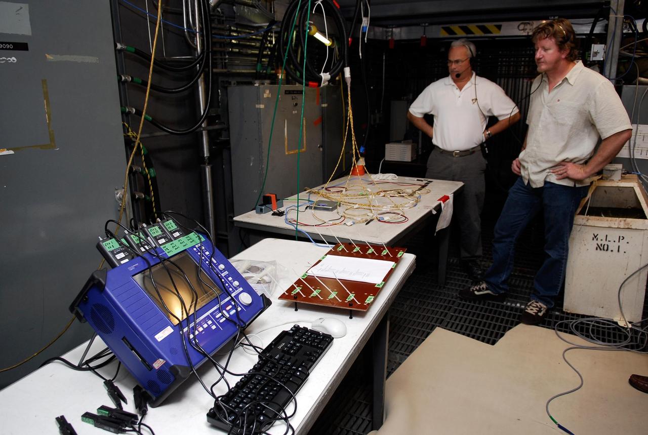
KENNEDY SPACE CENTER, FLA. -- On Launch Pad 39A, a technician explains how test equipment -- the blue monitor -- will be used to validate the circuit on test wiring from the electrical harness in space shuttle Atlantis' aft main engine compartment connected with the engine cut-off system. The test wiring leads from the tail mast on the mobile launcher platform to the interior where the Time Domain Reflectometry, or TDR, test equipment will be located to test the sensor system. Photo credit: NASA/Kim Shiflett

Jamie Szafran, from left, Mark Lewis and Curtis Ihlefeld work with the prototype of the Flexible Damage Detection System in a laboratory with a prototype at NASA's Kennedy Space Center in Florida. The system uses circuits printed on thin thermal film and specialized software. The system is designed to show where damage to a surface occurs and how severe it may be. It could offer astronauts a real-time update on their spacecraft's condition during a mission without requiring a spacewalk.
KENNEDY SPACE CENTER, FLA. -- In the Payload Hazardous Servicing Facility, the lander petals of the Mars Exploration Rover 2 (MER-2) have been reopened to allow technicians access to one of the spacecraft's circuit boards. A concern arose during prelaunch testing regarding how the spacecraft interprets signals sent from its main computer to peripherals in the cruise stage, lander and small deep space transponder. The MER Mission consists of two identical rovers set to launch in June 2003. The problem will be fixed on both rovers.
KENNEDY SPACE CENTER, FLA. -- In the Payload Hazardous Servicing Facility, a technician prepares to reopen the lander petals of the Mars Exploration Rover 2 (MER-2) to allow access to one of the spacecraft's circuit boards. A concern arose during prelaunch testing regarding how the spacecraft interprets signals sent from its main computer to peripherals in the cruise stage, lander and small deep space transponder. The MER Mission consists of two identical rovers set to launch in June 2003. The problem will be fixed on both rovers.
Curtis Ihlefeld, left, and Mark Lewis work with the prototype of the Flexible Damage Detection System in a laboratory with a prototype at NASA's Kennedy Space Center in Florida. The system uses circuits printed on thin thermal film and specialized software. The system is designed to show where damage to a surface occurs and how severe it may be. It could offer astronauts a real-time update on their spacecraft's condition during a mission without requiring a spacewalk.
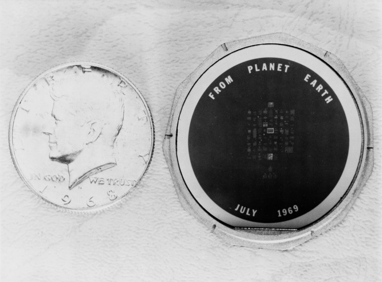
S69-39148 (July 1969) --- Close-up view of the one and one-half inch silicon disk which will be left on the moon by the Apollo 11 astronauts. The disk bears messages of goodwill from heads of state of many nations. The process used to make this wafer is the same as that used to manufacture integrated circuits for electronic equipment. It involves making tiny photographic images and depositing metal on the images. The Kennedy half-dollar illustrates the relative size of the memorial disk.
Jamie Szafran, from left, Mark Lewis and Curtis Ihlefeld work with the prototype of the Flexible Damage Detection System in a laboratory with a prototype at NASA's Kennedy Space Center in Florida. The system uses circuits printed on thin thermal film and specialized software. The system is designed to show where damage to a surface occurs and how severe it may be. It could offer astronauts a real-time update on their spacecraft's condition during a mission without requiring a spacewalk.
KENNEDY SPACE CENTER, FLA. -- In the Payload Hazardous Servicing Facility, preparations are under way to reopen the lander petals of the Mars Exploration Rover 2 (MER-2) to allow technicians access to one of the spacecraft's circuit boards. A concern arose during prelaunch testing regarding how the spacecraft interprets signals sent from its main computer to peripherals in the cruise stage, lander and small deep space transponder. The MER Mission consists of two identical rovers set to launch in June 2003. The problem will be fixed on both rovers.
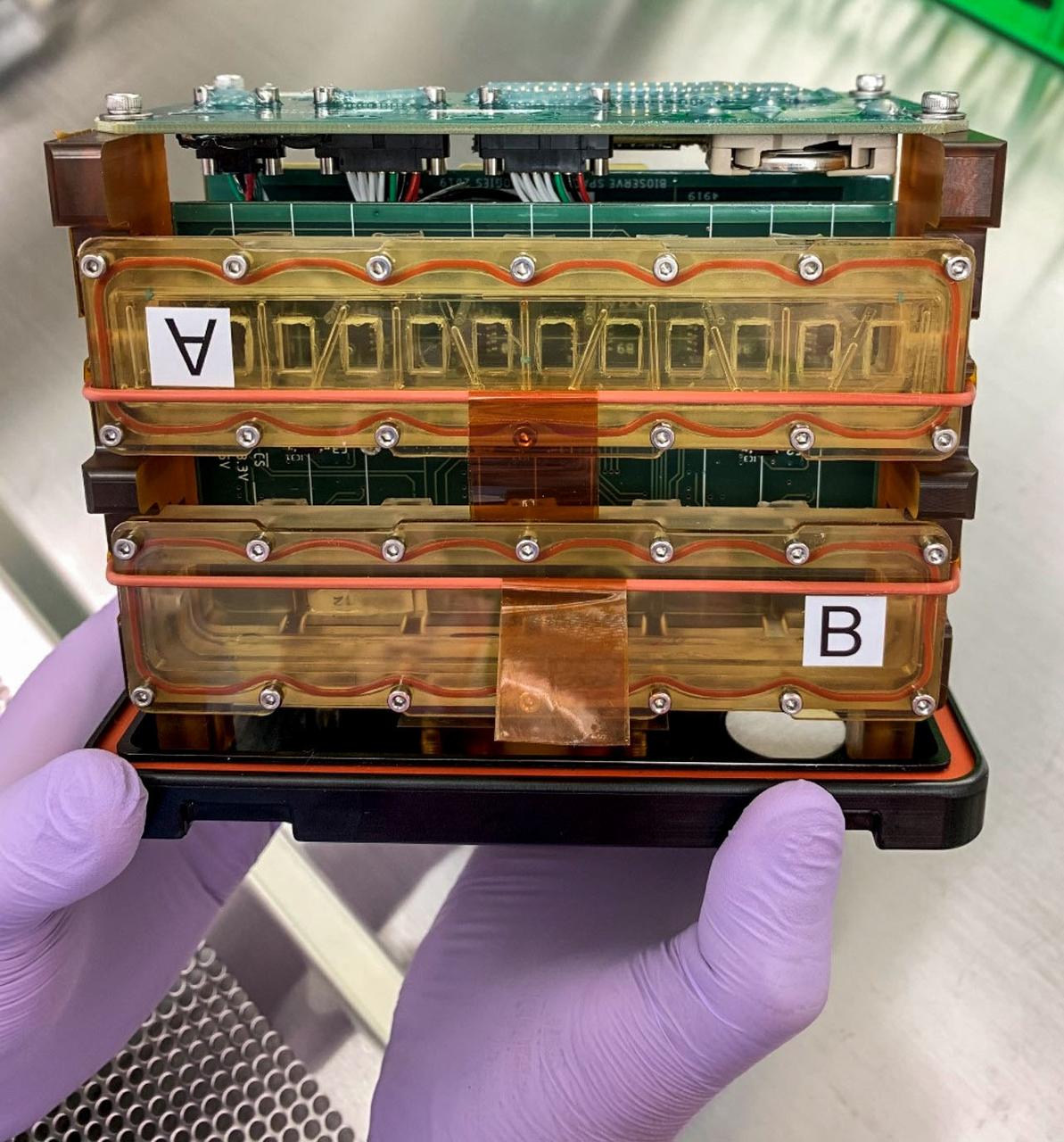
jsc2022e083015 (10/26/2022) --- A preflight image of tissue chambers loaded into the plate habitat (pHAB) for A Human iPSC-based 3D Microphysiological System for Modeling Cardiac Dysfunction in Microgravity (Engineered Heart Tissues-2) investigation. Each tissue chamber contains six tissues and is placed over magnetic sensors on a circuit board to measure contractile function of the Engineered Heart Tissues (EHTs). Image courtesy of Johns Hopkins University.
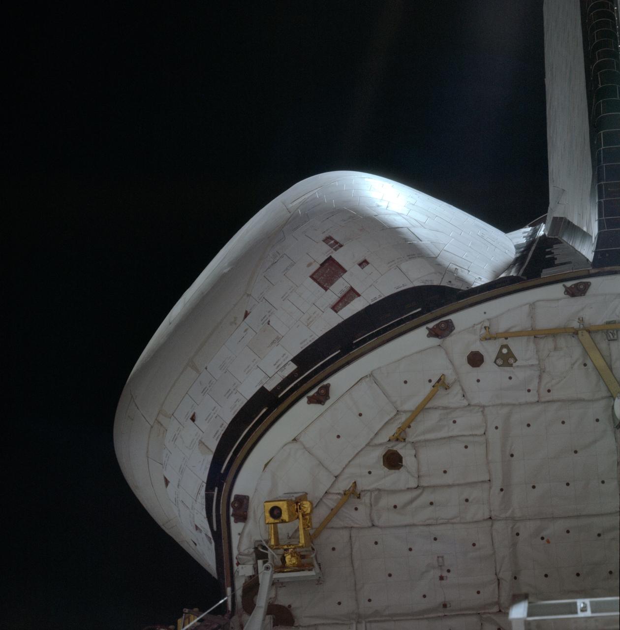
STS001-08-289 (12-14 April 1981) --- A 250mm Hasselblad view of the left OMS pod and missing tiles. Photo credit: NASA
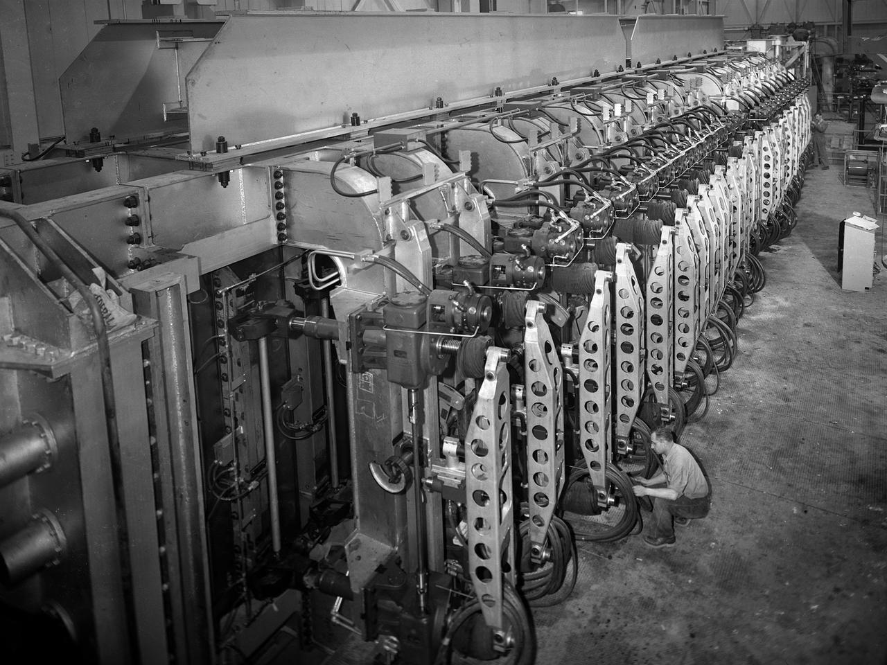
A mechanic checks the tubing on one of the many jacks which control the nozzle section of the 10- by 10-Foot Supersonic Wind Tunnel at the National Advisory Committee for Aeronautics (NACA) Lewis Flight Propulsion Laboratory. The 10- by 10-foot tunnel, which had its official opening in May 1956, was built under the Congressional Unitary Plan Act which coordinated wind tunnel construction at the NACA, Air Force, industry, and universities. The 10- by 10 was the largest of the three NACA tunnels built under the act. The 10- by 10 wind tunnel can be operated as a closed circuit for aerodynamic tests or as an open circuit for propulsion investigations. The 10-foot tall and 76-foot long stainless steel nozzle section just upstream from the test section can be adjusted to change the speed and composition of the air flow. Hydraulic jacks, seen in this photograph, flex the 1.37-inch thick walls of the tunnel nozzle. The size of the nozzle’s opening controls the velocity of the air through the test section. Seven General Electric motors capable of generating 25,000 horsepower produce the Mach 2.5 and 2.5 airflows. The facility was mostly operated at night due to its large power load requirements.
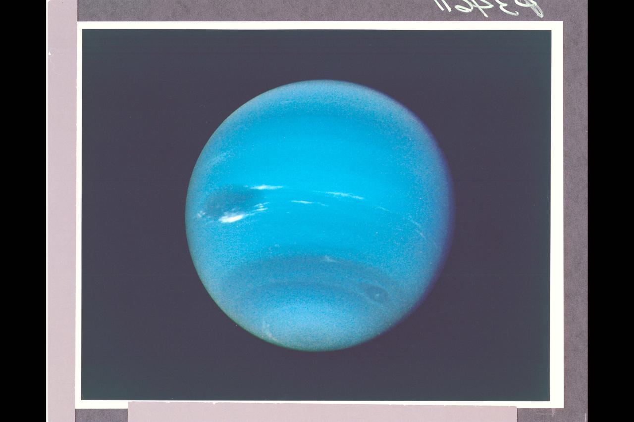
Photo by Voyager 2 (JPL) During August 16 and 17, 1989, the Voyager 2 narrow-angle camera was used to photograph Neptune almost continuously, recording approximately two and one-half rotations of the planet. These images represent the most complete set of full disk Neptune images that the spacecraft will acquire. This picture from the sequence shows two of the four cloud features which have been tracked by the Voyager cameras during the past two months. The large dark oval near the western limb (the left edge) is at a latitude of 22 degrees south and circuits Neptune every 18.3 hours. The bright clouds immediately to the south and east of this oval are seen to substantially change their appearances in periods as short as four hours. The second dark spot, at 54 degrees south latitude near the terminator (lower right edge), circuits Neptune every 16.1 hours. This image has been processed to enchance the visibility of small features, at some sacrifice of color fidelity. The Voyager Mission is conducted by JPL for NASA's Office of Space Science and Applications. (JPL Ref: A-34611 Voyager 2-N29)

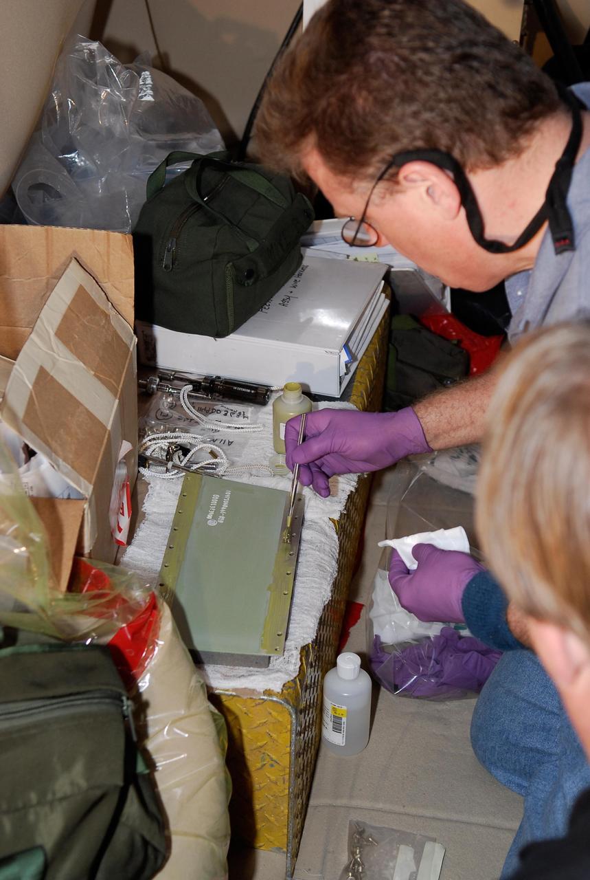
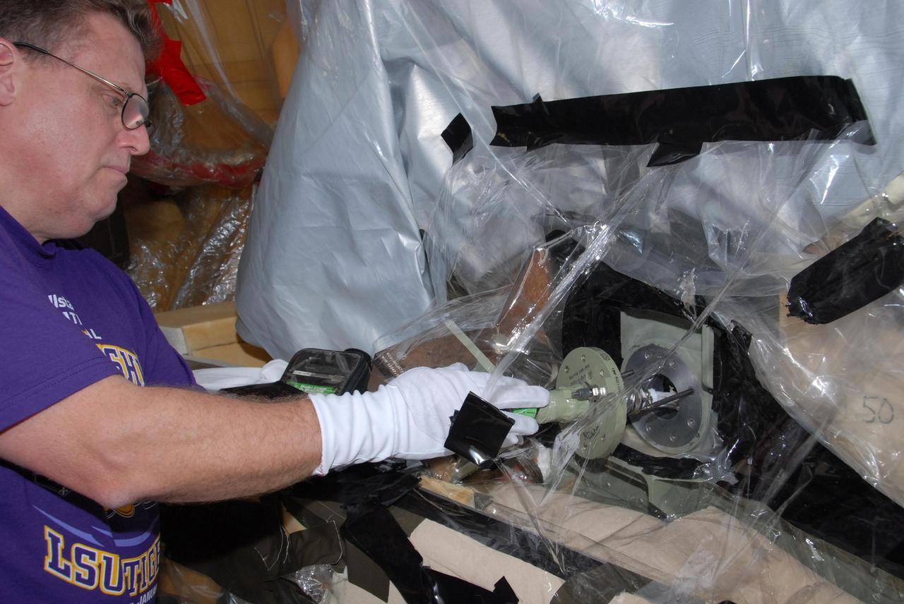
Goddard's Ritsko Wins 2011 SAVE Award The winner of the 2011 SAVE Award is Matthew Ritsko, a Goddard financial manager. His tool lending library would track and enable sharing of expensive space-flight tools and hardware after projects no longer need them. This set of images represents the types of tools used at NASA. To read more go to: <a href="http://www.nasa.gov/topics/people/features/ritsko-save.html" rel="nofollow">www.nasa.gov/topics/people/features/ritsko-save.html</a> Dr. Doug Rabin (Code 671) and PI La Vida Cooper (Code 564) inspect engineering samples of the HAS-2 imager which will be tested and readout using a custom ASIC with a 16-bit ADC (analog to digital converter) and CDS (correlated double sampling) circuit designed by the Code 564 ASIC group as a part of an FY10 IRAD. The purpose of the IRAD was to develop and high resolution digitizer for Heliophysics applications such as imaging. Future goals for the collaboration include characterization testing and eventually a sounding rocket flight of the integrated system. *ASIC= Application Specific Integrated Circuit NASA/GSFC/Chris Gunn
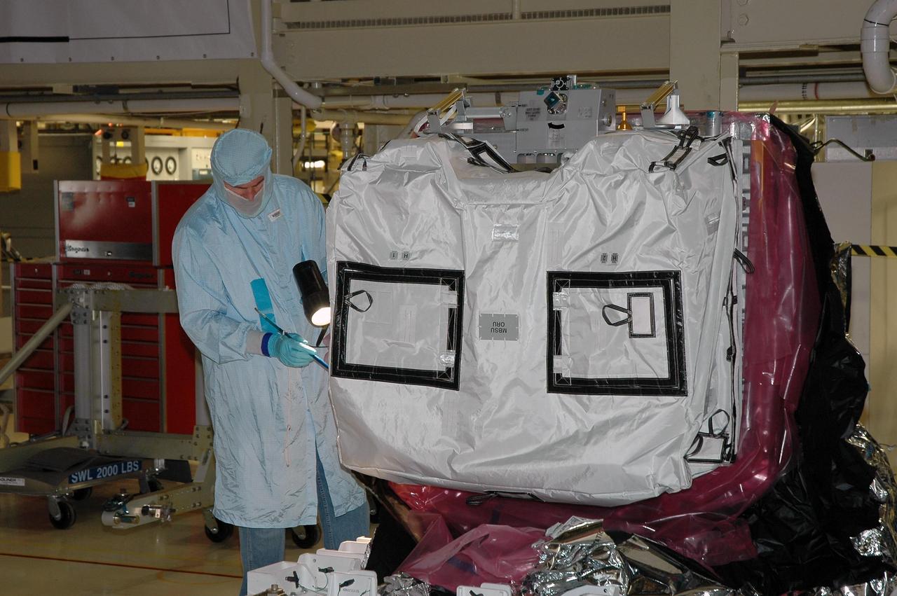
KENNEDY SPACE CENTER, Fla. -- In the Orbiter Processing Facility bay 3, a worker checks the cover on a main bus switching unit, part of the payload on mission STS-120. A main bus switching unit is used for power distribution, circuit protection and fault isolation on the space station's power system. The units route power to proper locations in the space station, such as from solar arrays through umbilicals into the U.S. Lab. The unit will be installed on the external stowage platform 2 attached to the Quest airlock for temporary storage. Discovery is targeted to launch mission STS-120 no earlier than Oct. 20. Photo credit: NASA/Jim Grossmann
KENNEDY SPACE CENTER, Fla. -- In the Orbiter Processing Facility bay 3, with the help of a crane, workers check the placement of a main bus switching unit in Discovery's payload bay. A main bus switching unit is used for power distribution, circuit protection and fault isolation on the space station's power system. The units route power to proper locations in the space station, such as from solar arrays through umbilicals into the U.S. Lab. The unit will be installed on the external stowage platform 2 attached to the Quest airlock for temporary storage. Discovery is targeted to launch mission STS-120 no earlier than Oct. 20. Photo credit: NASA/Jim Grossmann
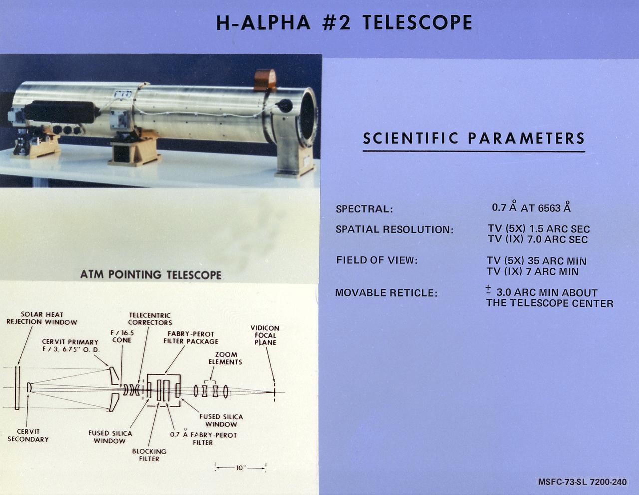
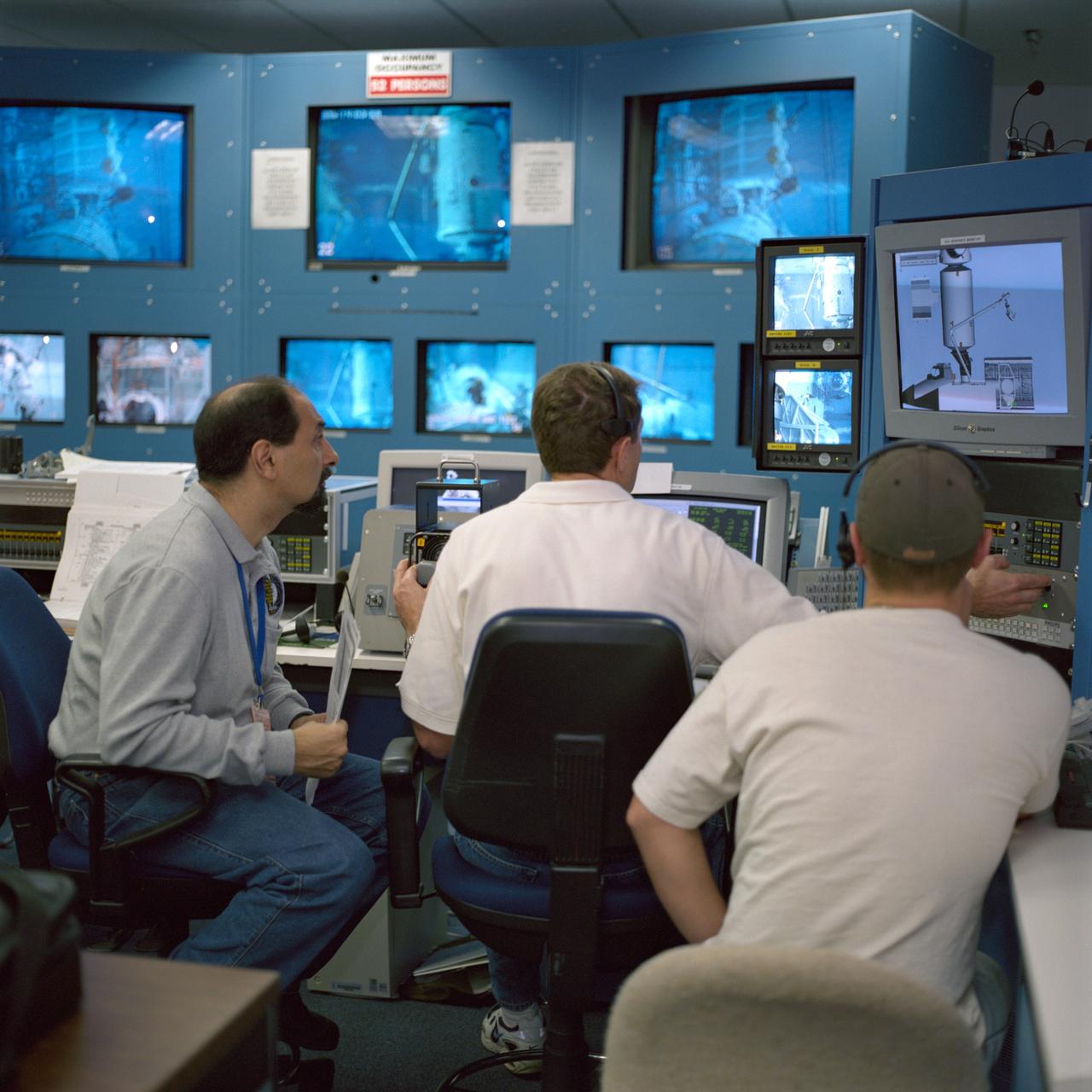
This chart describes the Hydrogen-Alpha (H-Alpha) #2 Telescope, one of eight major solar study facilities on the Skylab Apollo Telescope Mount (ATM). There were two H-Alpha telescopes on the ATM that were used primarily to point the ATM and keep a continuous photographic record during solar observation periods. Both telescopes gave the Skylab astronauts a real-time picture of the Sun in the red light of the H-Alpha spectrum through a closed-circuit television. The H-Alpha #1 telescope provided simultaneous photographic and ultraviolet (UV) pictures, while the #2 telescope operated only in the TV mode. The Marshall Space Flight Center was responsible for development of the H-Alpha Telescopes.
JSC2000-07406 (1 December 2000) --- Astronaut Umberto Guidoni (left), STS-100 mission specialist representing the European Space Agency (ESA), views a closed-circuit televising of an underwater space walk simulation performed by two crew mates. The simulation of the scheduled spring 2001 space walk took place at the Neutral Buoyancy Laboratory (NBL) at the Sonny Carter Training Facility. Astronaut Jeffrey S. Ashby, pilot, is at center. Astronauts Scott E. Parazynski of the NASA-Johnson Space Center and Chris A. Hadfield of the Canadian Space Agency (CSA), both mission specialists and both equipped with training versions of the extravehicular mobility unit (EMU) space suits, were in the water at the time.
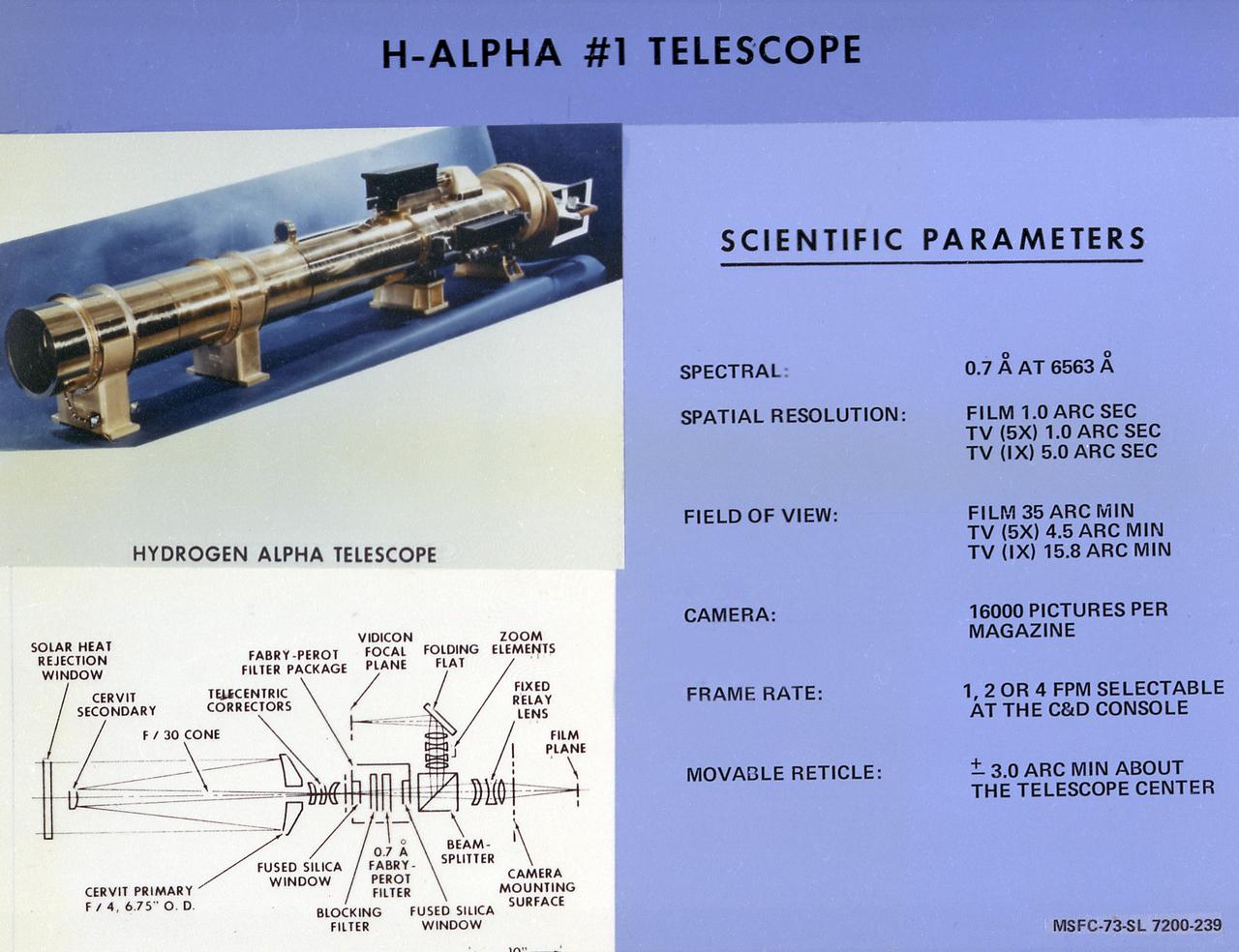
This chart describes the Hydrogen-Alpha (H-Alpha) #1 Telescope, one of eight major solar study facilities on the Skylab Apollo Telescope Mount (ATM). There were two H-Alpha telescopes on the ATM that were used primarily to point the ATM and keep a continuous photographic record during the solar observation periods. Both telescopes gave the Skylab astronauts a real-time picture of the Sun in the red light of the H-Alpha spectrum through a closed-circuit television. The H-Alpha #1 Telescope provided simultaneous photographic and ultraviolet (UV) pictures, while the #2 Telescope operated only in the TV mode. The Marshall Space Flight Center was responsible for development of the H-Alpha Telescopes.
KENNEDY SPACE CENTER, Fla. -- In the Orbiter Processing Facility bay 3, a crane moves the main bus switching unit that will be installed in Discovery's payload bay. The unit is part of the payload on mission STS-120. A main bus switching unit is used for power distribution, circuit protection and fault isolation on the space station's power system. The units route power to proper locations in the space station, such as from solar arrays through umbilicals into the U.S. Lab. The unit will be installed on the external stowage platform 2 attached to the Quest airlock for temporary storage. Discovery is targeted to launch mission STS-120 no earlier than Oct. 20. Photo credit: NASA/Jim Grossmann
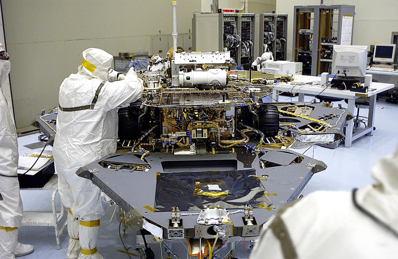
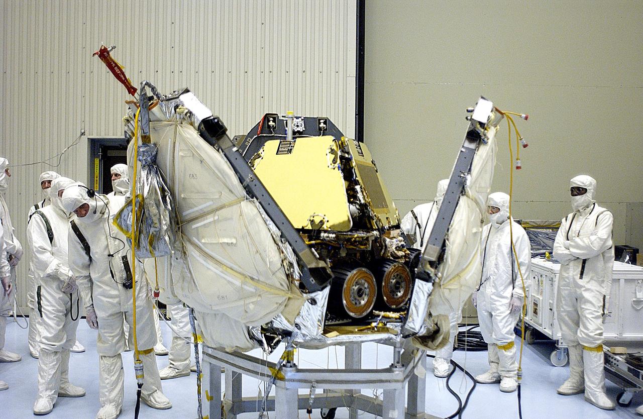
KENNEDY SPACE CENTER, FLA. -- In the Payload Hazardous Servicing Facility, the lander petals of the Mars Exploration Rover 2 (MER-2) have been reopened and its solar panels deployed to allow technicians access to the spacecraft to remove one of its circuit boards. A concern arose during prelaunch testing regarding how the spacecraft interprets signals sent from its main computer to peripherals in the cruise stage, lander and small deep space transponder. The MER Mission consists of two identical rovers set to launch in June 2003. The problem will be fixed on both rovers.
KENNEDY SPACE CENTER, Fla. -- In the Orbiter Processing Facility bay 3, the main bus switching unit that is part of the payload on mission STS-120 is being prepared for inspection. A main bus switching unit is used for power distribution, circuit protection and fault isolation on the space station's power system. The units route power to proper locations in the space station, such as from solar arrays through umbilicals into the U.S. Lab. The unit will be installed on the external stowage platform 2 attached to the Quest airlock for temporary storage. Discovery is targeted to launch mission STS-120 no earlier than Oct. 20. Photo credit: NASA/Jim Grossmann
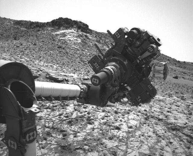
This image from the Navigation Camera (Navcam) on NASA's Curiosity Mars rover shows the position in which the rover held its arm for several days after a transient short circuit triggered onboard fault-protection programming to halt arm activities on Feb. 27, 2015, the 911th Martian day, or sol, of the rover's work on Mars. The rover team chose to hold the arm in the same position for several days of tests to diagnose the underlying cause of the Sol 911 event. Observations with instruments on the rover's mast continued during this period. The Navcam took this image on March 4, 2015, during Sol 915. http://photojournal.jpl.nasa.gov/catalog/PIA19147
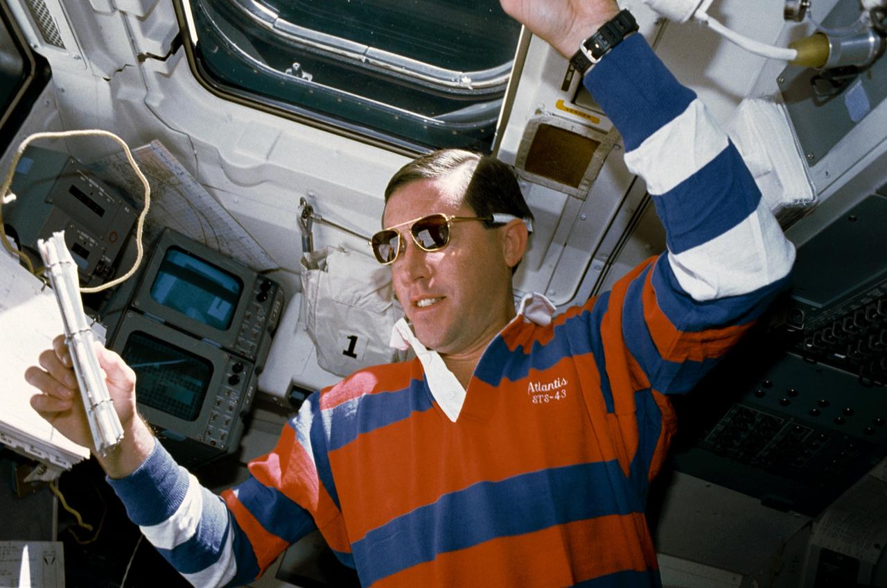
STS043-04-032 (11 Aug 1991) --- STS-43 Pilot Michael A. Baker, wearing sunglasses, reviews a checklist on the aft flight deck of Atlantis, Orbiter Vehicle (OV) 104. He is monitoring data associated with the Space Station Heat Pipe Advanced Radiator Element II (SHARE-II) located in OV-104's payload bay (PLB) from his position in front of the aft flight deck viewing windows. Behind Baker are the closed circuit television (CCTV) monitors and above his head is overhead window W8.
KENNEDY SPACE CENTER, Fla. -- In the Orbiter Processing Facility bay 3, workers are ready to move a main bus switching unit into Discovery's payload bay. A main bus switching unit is used for power distribution, circuit protection and fault isolation on the space station's power system. The units route power to proper locations in the space station, such as from solar arrays through umbilicals into the U.S. Lab. The unit will be installed on the external stowage platform 2 attached to the Quest airlock for temporary storage. Discovery is targeted to launch mission STS-120 no earlier than Oct. 20. Photo credit: NASA/Jim Grossmann
KENNEDY SPACE CENTER, Fla. -- In the Orbiter Processing Facility bay 3, a crane lowers the main bus switching unit into Discovery's payload bay. The unit is part of the payload on mission STS-120.A main bus switching unit is used for power distribution, circuit protection and fault isolation on the space station's power system. The units route power to proper locations in the space station, such as from solar arrays through umbilicals into the U.S. Lab. The unit will be installed on the external stowage platform 2 attached to the Quest airlock for temporary storage. Discovery is targeted to launch mission STS-120 no earlier than Oct. 20. Photo credit: NASA/Jim Grossmann

KENNEDY SPACE CENTER, FLA. -- In the Payload Hazardous Servicing Facility, the lander petals of the Mars Exploration Rover 2 (MER-2) have been reopened and its solar panels deployed to allow technicians access to the spacecraft to remove one of its circuit boards. A concern arose during prelaunch testing regarding how the spacecraft interprets signals sent from its main computer to peripherals in the cruise stage, lander and small deep space transponder. The MER Mission consists of two identical rovers set to launch in June 2003. The problem will be fixed on both rovers.
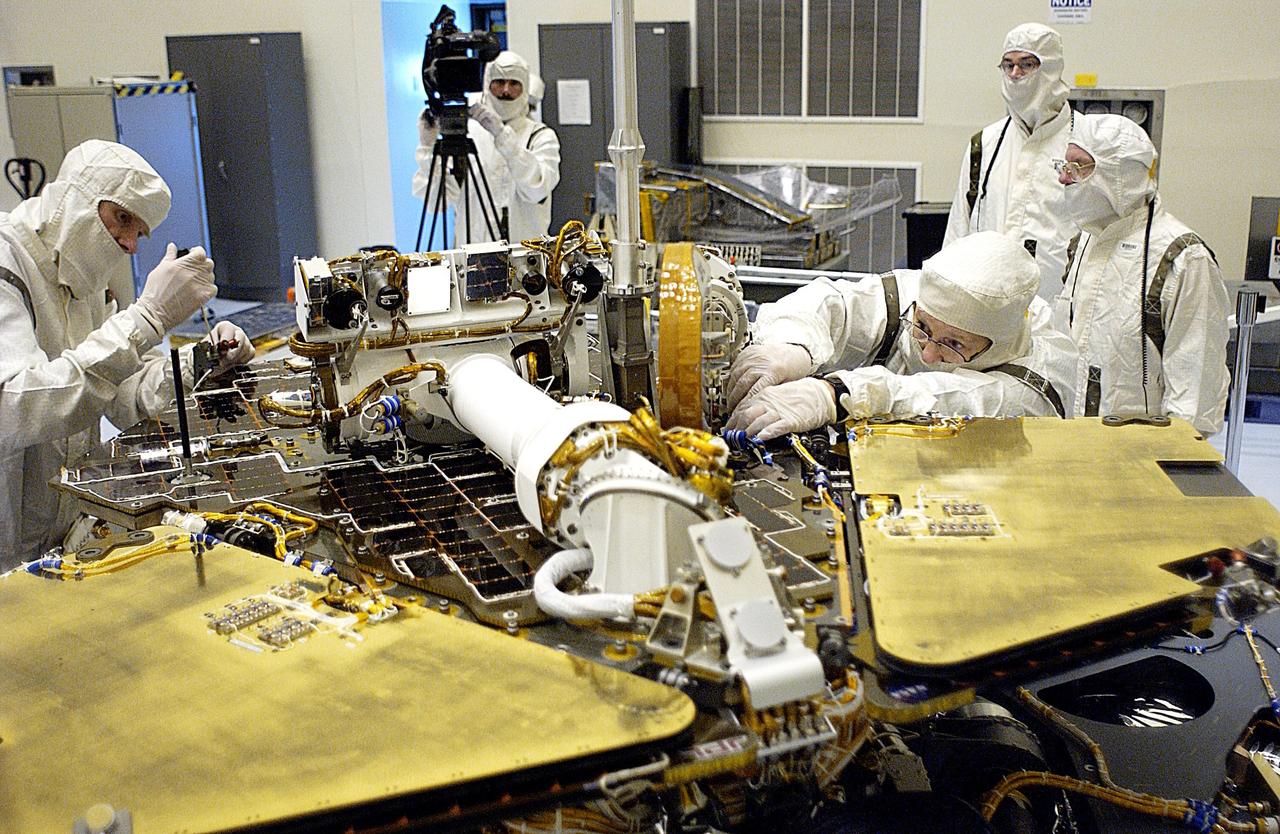
KENNEDY SPACE CENTER, FLA. -- In the Payload Hazardous Servicing Facility, technicians remove one of the circuit boards on the Mars Exploration Rover 2 (MER-2). To gain access to the spacecraft, its lander petals were reopened and its solar panels deployed. A concern arose during prelaunch testing regarding how the spacecraft interprets signals sent from its main computer to peripherals in the cruise stage, lander and small deep space transponder. The MER Mission consists of two identical rovers set to launch in June 2003. The problem will be fixed on both rovers.
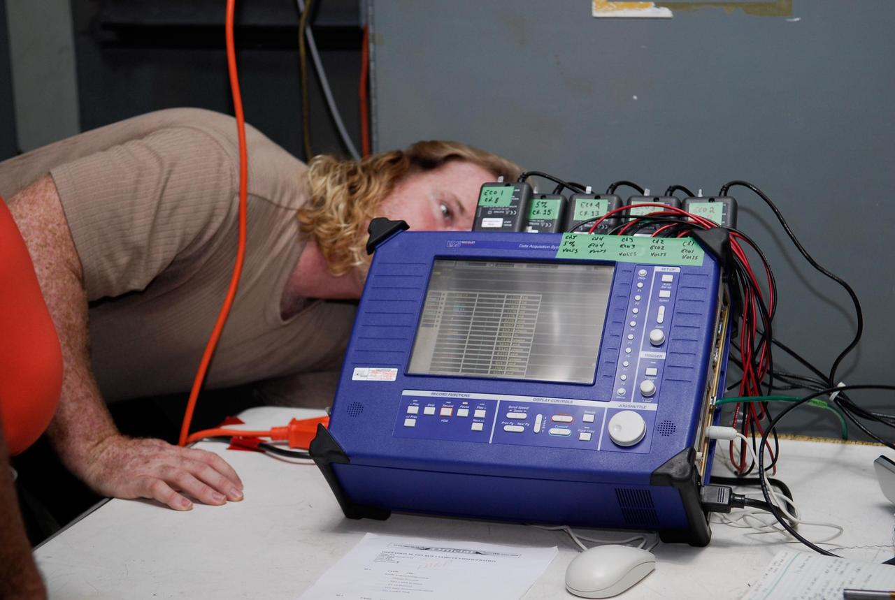
KENNEDY SPACE CENTER, FLA. -- On Launch Pad 39A at NASA's Kennedy Space Center, a technician checks the blue monitor that will be used to validate the circuit on test wiring during the tanking test on space shuttle Atlantis' external tank. The test wiring has been spliced into an electrical harness in the aft main engine compartment connected with the engine cut-off, or ECO, sensor system. The attached wiring leads to the interior of the mobile launcher platform where the time domain reflectometry, or TDR, test equipment is located. Photo credit: NASA/Kim Shiflett
KENNEDY SPACE CENTER, Fla. -- In the Orbiter Processing Facility bay 3, workers check the placement of a main bus switching unit in Discovery's payload bay. A main bus switching unit is used for power distribution, circuit protection and fault isolation on the space station's power system. The units route power to proper locations in the space station, such as from solar arrays through umbilicals into the U.S. Lab. The unit will be installed on the external stowage platform 2 attached to the Quest airlock for temporary storage. Discovery is targeted to launch mission STS-120 no earlier than Oct. 20. Photo credit: NASA/Jim Grossmann
KENNEDY SPACE CENTER, Fla. -- In the Orbiter Processing Facility bay 3, STS-120Mission Specialist Paolo Nespoli practices using a tool on the main bus switching unit that is part of the payload on the mission. A main bus switching unit is used for power distribution, circuit protection and fault isolation on the space station's power system. The units route power to proper locations in the space station, such as from solar arrays through umbilicals into the U.S. Lab. The unit will be installed on the external stowage platform 2 attached to the Quest airlock for temporary storage. Discovery is targeted to launch mission STS-120 no earlier than Oct. 20. Photo credit: NASA/Jim Grossmann
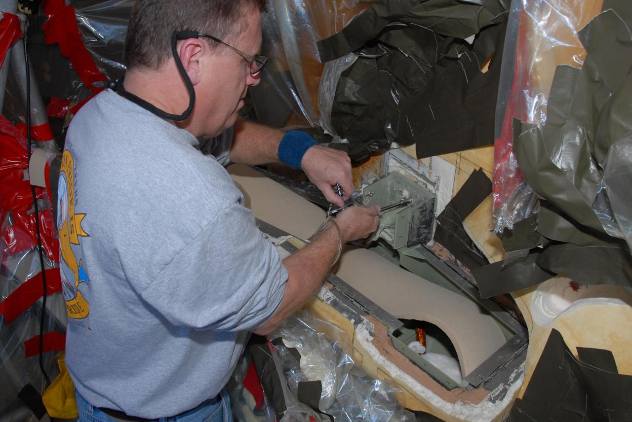
KENNEDY SPACE CENTER, FLA. -- On Launch Pad 39A at NASA's Kennedy Space Center, a technician begins attaching the cover over the engine cutoff, or ECO, sensor system connector and wiring on space shuttle Atlantis' external tank. The feed-through connector passes the wires from the inside of the tank to the outside. Results of a tanking test on Dec. 18 pointed to an open circuit in the feed-through connector wiring, which is located at the base of the tank. The pins in the replacement connector were precisely soldered to create a connection that allows sensors inside the tank to send signals to the computers onboard Atlantis. The launch date for the shuttle's STS-122 mission has now been targeted for Feb. 7. Photo credit: NASA/Kim Shiflett

KENNEDY SPACE CENTER, FLA. -- On Launch Pad 39A at NASA's Kennedy Space Center, foam insulation is being trimmed for placement around the engine cutoff, or ECO, sensor system connector and wiring on space shuttle Atlantis' external tank. The foam was removed to enable engineers to remove and replace a feed-through ECO sensor connector on the tank. The feed-through connector passes the wires from the inside of the tank to the outside. Results of a tanking test on Dec. 18 pointed to an open circuit in the feed-through connector wiring, which is located at the base of the tank. The pins in the replacement connector were precisely soldered to create a connection that allows sensors inside the tank to send signals to the computers onboard Atlantis. The launch date for the shuttle's STS-122 mission has now been targeted for Feb. 7. Photo credit: NASA/Kim Shiflett
Engineer Paul Reader and his colleagues take environmental measurements during testing of a 20-inch diameter ion engine in a vacuum tank at the Electric Propulsion Laboratory (EPL). Researchers at the Lewis Research Center were investigating the use of a permanent-magnet circuit to create the magnetic field required power electron bombardment ion engines. Typical ion engines use a solenoid coil to create this magnetic field. It was thought that the substitution of a permanent magnet would create a comparable magnetic field with a lower weight. Testing of the magnet system in the EPL vacuum tanks revealed no significant operational problems. Reader found the weight of the two systems was similar, but that the thruster’s efficiency increased with the magnet. The EPL contained a series of large vacuum tanks that could be used to simulate conditions in space. Large vacuum pumps reduced the internal air pressure, and a refrigeration system created the cryogenic temperatures found in space.
KENNEDY SPACE CENTER, FLA. -- On Launch Pad 39A at NASA's Kennedy Space Center, technicians prepare the cover to be installed over the engine cutoff, or ECO, sensor system connector and wiring on space shuttle Atlantis' external tank. The feed-through connector passes the wires from the inside of the tank to the outside. Results of a tanking test on Dec. 18 pointed to an open circuit in the feed-through connector wiring, which is located at the base of the tank. The pins in the replacement connector were precisely soldered to create a connection that allows sensors inside the tank to send signals to the computers onboard Atlantis. The launch date for the shuttle's STS-122 mission has now been targeted for Feb. 7. Photo credit: NASA/Kim Shiflett
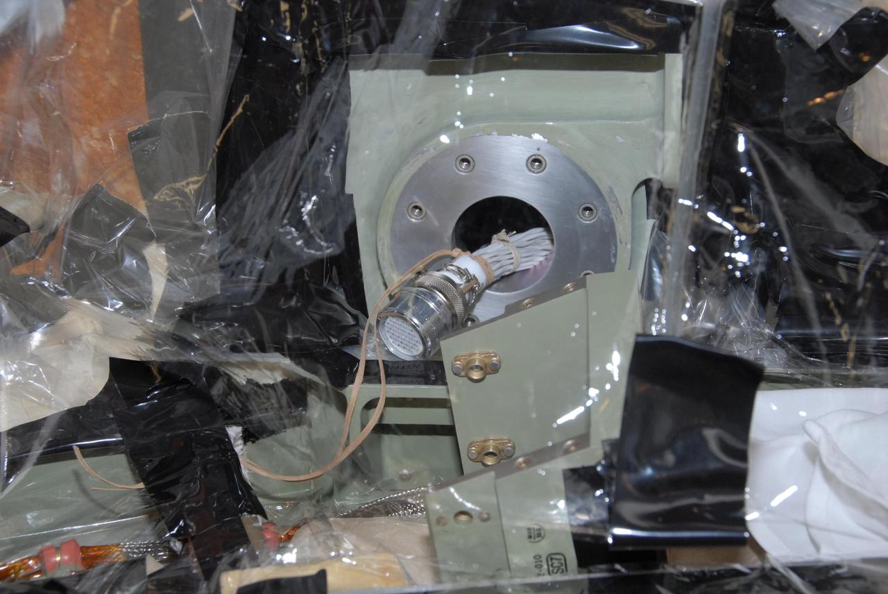
KENNEDY SPACE CENTER, FLA. -- This closeup shows the internal connector to which the replacement feed-through connector in the engine cutoff, or ECO, sensor system on space shuttle Atlantis' external tank will be installed. The feed-through connector passes the wires from the inside of the tank to the outside. Results of a tanking test on Dec. 18 pointed to an open circuit in the feed-through connector wiring, which is located at the base of the tank. The pins in the replacement connector have been precisely soldered to create a connection that allows sensors inside the tank to send signals to the computers onboard Atlantis. The work is being done on Launch Pad 39A. Space shuttle Atlantis is now targeted for launch on Feb. 7. Photo credit: NASA/George Shelton
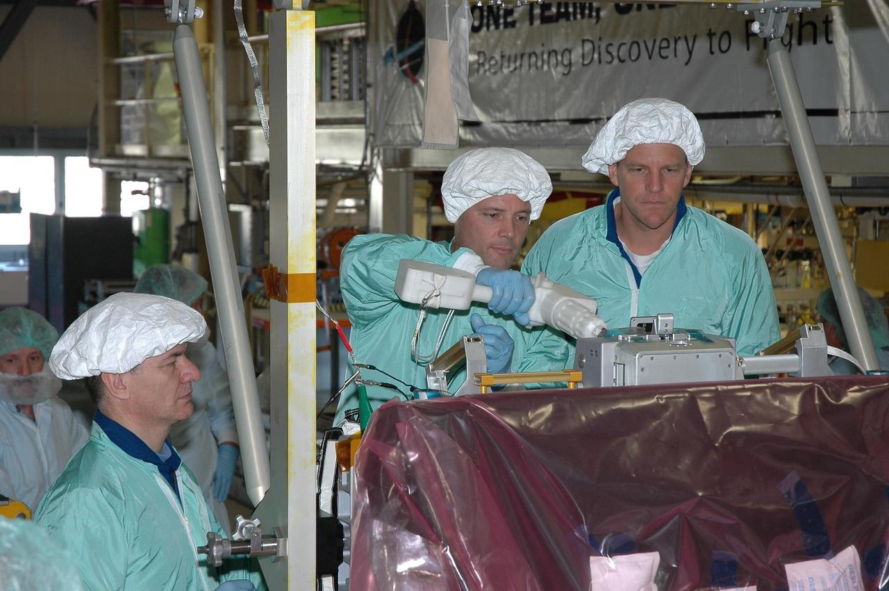
KENNEDY SPACE CENTER, Fla. -- In the Orbiter Processing Facility bay 3, STS-120 crew members inspect the main bus switching unit that is part of the payload on their mission. From left are Mission Specialists Paolo Nespoli, Doug Wheelock and Scott Parazynski. Wheelock is practicing using a tool on the unit. Nespoli represents the European Space Agency. A main bus switching unit is used for power distribution, circuit protection and fault isolation on the space station's power system. The units route power to proper locations in the space station, such as from solar arrays through umbilicals into the U.S. Lab. The unit will be installed on the external stowage platform 2 attached to the Quest airlock for temporary storage. Discovery is targeted to launch mission STS-120 no earlier than Oct. 20. Photo credit: NASA/Jim Grossmann
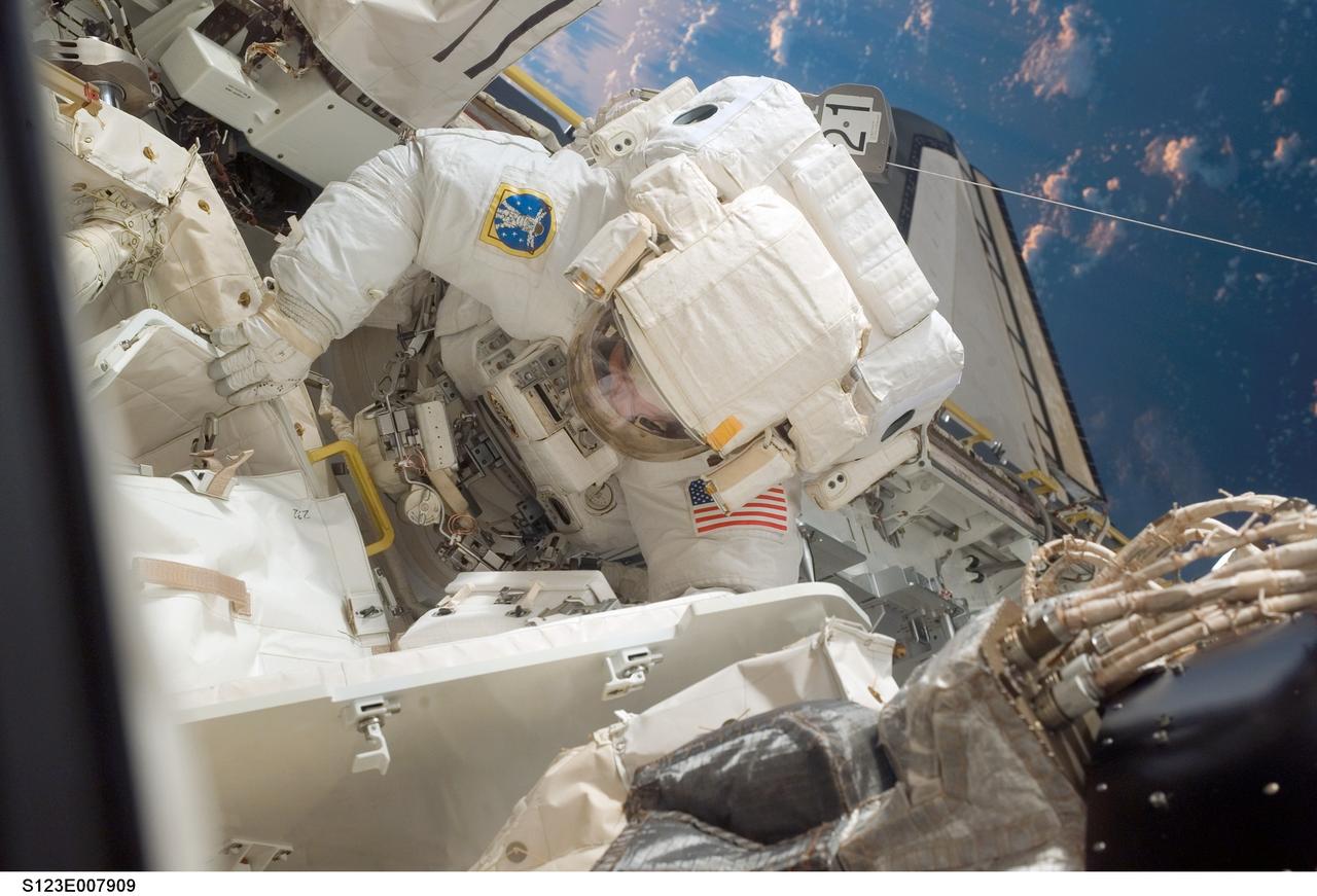
S123-E-007909 (21 March 2008) --- Astronaut Robert L. Behnken, STS-123 mission specialist, participates in the mission's fourth scheduled session of extravehicular activity (EVA) as construction and maintenance continue on the International Space Station. During the 6-hour, 24-minute spacewalk, Behnken and astronaut Mike Foreman (out of frame), mission specialist, replaced a failed Remote Power Control Module -- essentially a circuit breaker -- on the station's truss. The spacewalkers also tested a repair method for damaged heat resistant tiles on the space shuttle. This technique used a caulk-gun-like tool named the Tile Repair Ablator Dispenser to dispense a material called Shuttle Tile Ablator-54 into purposely damaged heat shield tiles. The sample tiles will be returned to Earth to undergo extensive testing on the ground.

S123-E-007838 (21 March 2008) --- Astronauts Robert L. Behnken (top) and Mike Foreman, both STS-123 mission specialists, participate in the mission's fourth scheduled session of extravehicular activity (EVA) as construction and maintenance continue on the International Space Station. During the 6-hour, 24-minute spacewalk, Behnken and Foreman replaced a failed Remote Power Control Module -- essentially a circuit breaker -- on the station's truss. The spacewalkers also tested a repair method for damaged heat resistant tiles on the space shuttle. This technique used a caulk-gun-like tool named the Tile Repair Ablator Dispenser to dispense a material called Shuttle Tile Ablator-54 into purposely damaged heat shield tiles. The sample tiles will be returned to Earth to undergo extensive testing on the ground.
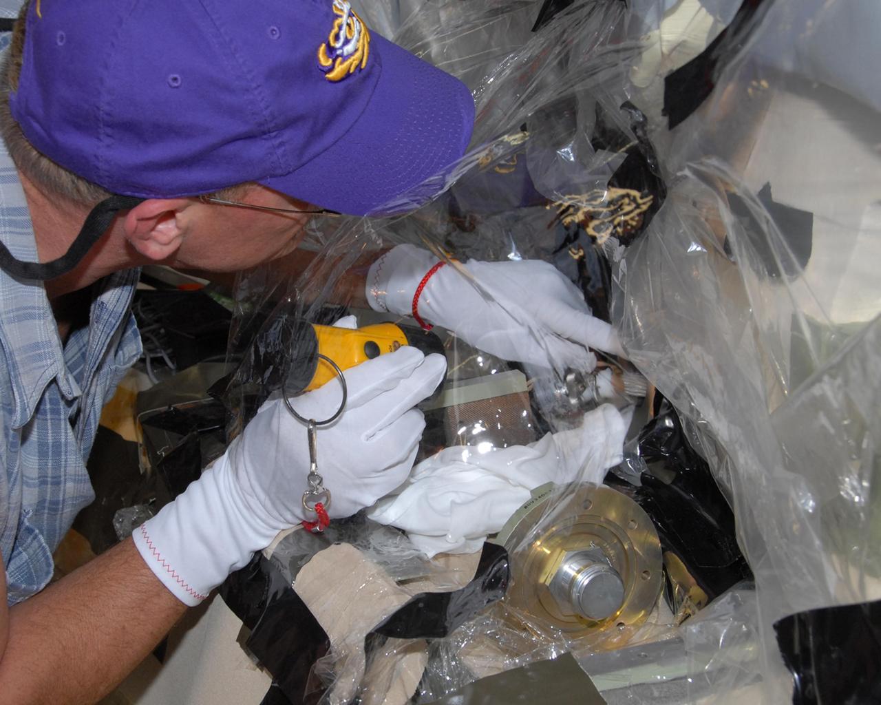
KENNEDY SPACE CENTER, FLA. -- Mike Berger, with Lockheed Martin, examines the internal connector on space shuttle Atlantis' external tank to which the replacement feed-through connector in the engine cutoff, or ECO, sensor system will be attached. The replacement connector is seen below Berger's hand. The feed-through connector passes the wires from the inside of the tank to the outside. Results of a tanking test on Dec. 18 pointed to an open circuit in the feed-through connector wiring, which is located at the base of the tank. The pins in the replacement connector have been precisely soldered to create a connection that allows sensors inside the tank to send signals to the computers onboard Atlantis. The work is being done on Launch Pad 39A. Space shuttle Atlantis is now targeted for launch on Feb. 7. Photo credit: NASA/George Shelton
KENNEDY SPACE CENTER, FLA. -- At Launch Pad 39A, a team of external tank specialists from Lockheed Martin and the United Space Alliance undertakes the task of removing the hydrogen feed-through connector in support of space shuttle Atlantis' STS-122 mission. Here, a technician removes a pair of support brackets. Some of the tank's engine cutoff sensors, or ECO sensors, failed during propellant tanking for launch attempts on Dec. 6 and Dec. 9. Results of a tanking test on Dec. 18 pointed to an open circuit in the feed-through connector wiring, which is located at the base of the tank. The feed-through connector passes the wires from the inside of the tank to the outside. After the data from additional testing on the connector is analyzed, shuttle program managers will decide on a forward plan. Launch of STS-122 is targeted for January 2008. Photo credit: NASA/George Shelton
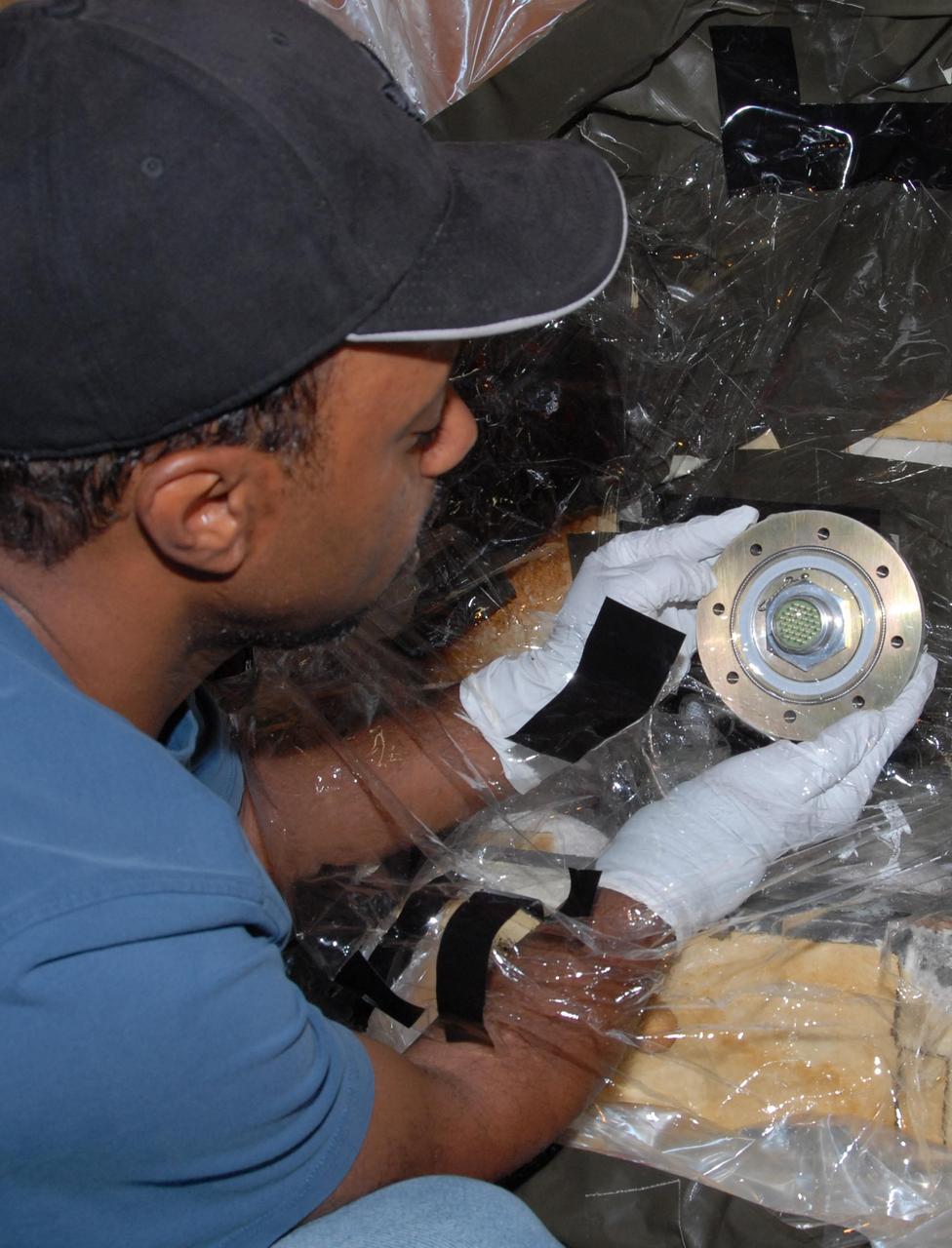
KENNEDY SPACE CENTER, FLA. -- At Launch Pad 39A, a team of external tank specialists from Lockheed Martin and the United Space Alliance undertakes the task of removing the hydrogen feed-through connector in support of space shuttle Atlantis' STS-122 mission. Here, a technician inspects the connector just removed from the external tank. Some of the tank's engine cutoff sensors, or ECO sensors, failed during propellant tanking for launch attempts on Dec. 6 and Dec. 9. Results of a tanking test on Dec. 18 pointed to an open circuit in the feed-through connector wiring, which is located at the base of the tank. The feed-through connector passes the wires from the inside of the tank to the outside. After the data from additional testing on the connector is analyzed, shuttle program managers will decide on a forward plan. Launch of STS-122 is targeted for January 2008. Photo credit: NASA/George Shelton
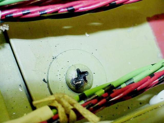
KENNEDY SPACE CENTER, FLA. -- In the orbiter Columbia's payload bay, the head of a screw (shown here) is identified as the probable cause of damage to a wire that caused a short circuit in two separate main engine controllers during launch of mission STS-93. As a result of the findings of electrical wiring inspections, Shuttle program managers have decided to inspect the wiring in Endeavour's payload bay before its next mission, STS-99. The inspection and possible repair work will lead to a delayed launch date no earlier than Oct.7. The primary payload of the mission is the Shuttle Radar Topography Mission, a specially modified radar system that will gather data for the most accurate and complete topographic map of the Earth's surface that has ever been assembled
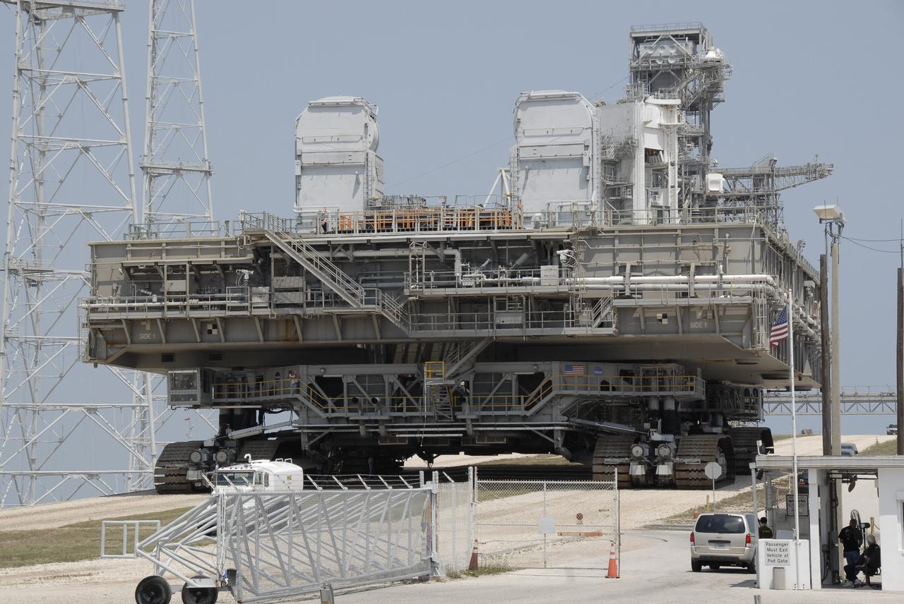
CAPE CANAVERAL, Fla. – At NASA's Kennedy Space Center in Florida, the mobile launcher platform that was turned over from the shuttle program to the Constellation Program last month moves off Kennedy's Launch Pad 39B via the crawler-transporter underneath. The platform will be rolled into the Vehicle Assembly Building's High Bay 3 in preparation for the Ares I-X flight test this summer. Ares I-X is the test vehicle for the Ares I, which is part of the Constellation Program to return men to the moon and beyond. Ground Control System hardware was installed in MLP-1 in December 2008. The platform was moved to the launch pad to check out the installed hardware with the Launch Control Center Firing Room 1 equipment, using the actual circuits that will be used when the fully stacked Ares I-X vehicle is rolled out later this year for launch. Photo credit: NASA/Kim Shiflett
KENNEDY SPACE CENTER, FLA. -- At Launch Pad 39A, a team of external tank specialists from Lockheed Martin and the United Space Alliance undertakes the task of removing the hydrogen feed-through connector in support of space shuttle Atlantis' STS-122 mission. Here, a technician cuts the external connector cable. Some of the tank's engine cutoff sensors, or ECO sensors, failed during propellant tanking for launch attempts on Dec. 6 and Dec. 9. Results of a tanking test on Dec. 18 pointed to an open circuit in the feed-through connector wiring, which is located at the base of the tank. The feed-through connector passes the wires from the inside of the tank to the outside. After the data from additional testing on the connector is analyzed, shuttle program managers will decide on a forward plan. Launch of STS-122 is targeted for January 2008. Photo credit: NASA/George Shelton
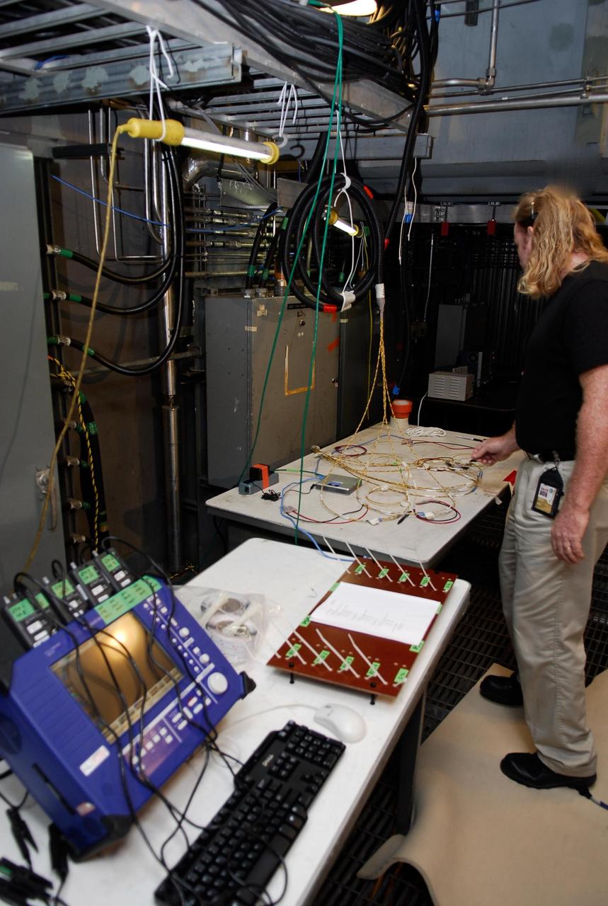
KENNEDY SPACE CENTER, FLA. -- On Launch Pad 39A, a technician checks cables and wires that will be used in the Time Domain Reflectometry, or TDR, test on engine cut-off sensors, or ECO, in space shuttle Atlantis' external tank. The test equipment -- blue monitor at left-- will be used to validate the circuit on the test wiring before hooking it up to the test box. The shuttle's planned launches on Dec. 6 and Dec. 9 were postponed because of false readings from the part of the ECO system that monitors the liquid hydrogen section of the tank. The liftoff date from NASA's Kennedy Space Center, Florida, is now targeted for Jan. 10, depending on the resolution of the problem in the fuel sensor system. Photo credit: NASA/Kim Shiflett
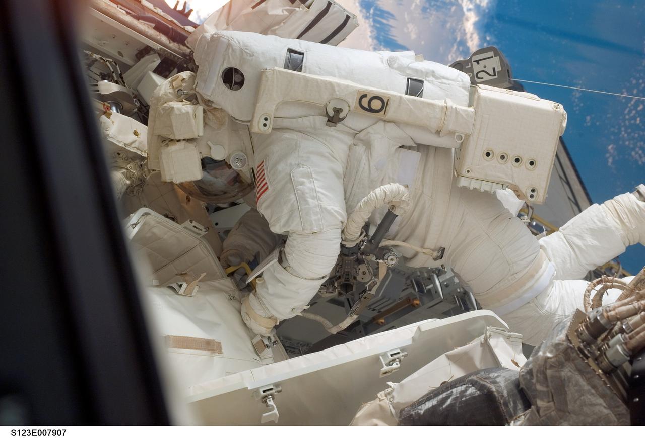
S123-E-007907 (21 March 2008) --- Astronaut Robert L. Behnken, STS-123 mission specialist, participates in the mission's fourth scheduled session of extravehicular activity (EVA) as construction and maintenance continue on the International Space Station. During the 6-hour, 24-minute spacewalk, Behnken and astronaut Mike Foreman (out of frame), mission specialist, replaced a failed Remote Power Control Module -- essentially a circuit breaker -- on the station's truss. The spacewalkers also tested a repair method for damaged heat resistant tiles on the space shuttle. This technique used a caulk-gun-like tool named the Tile Repair Ablator Dispenser to dispense a material called Shuttle Tile Ablator-54 into purposely damaged heat shield tiles. The sample tiles will be returned to Earth to undergo extensive testing on the ground.
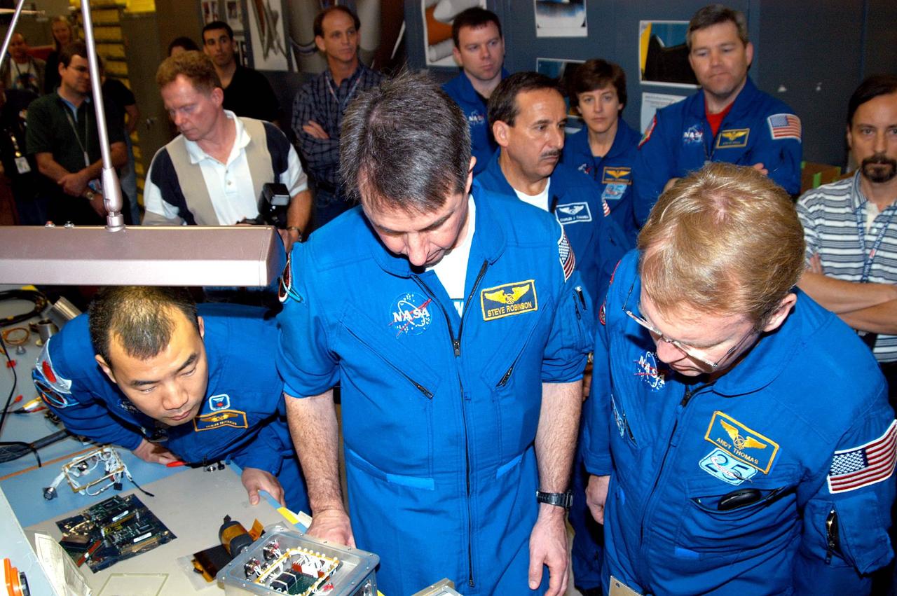
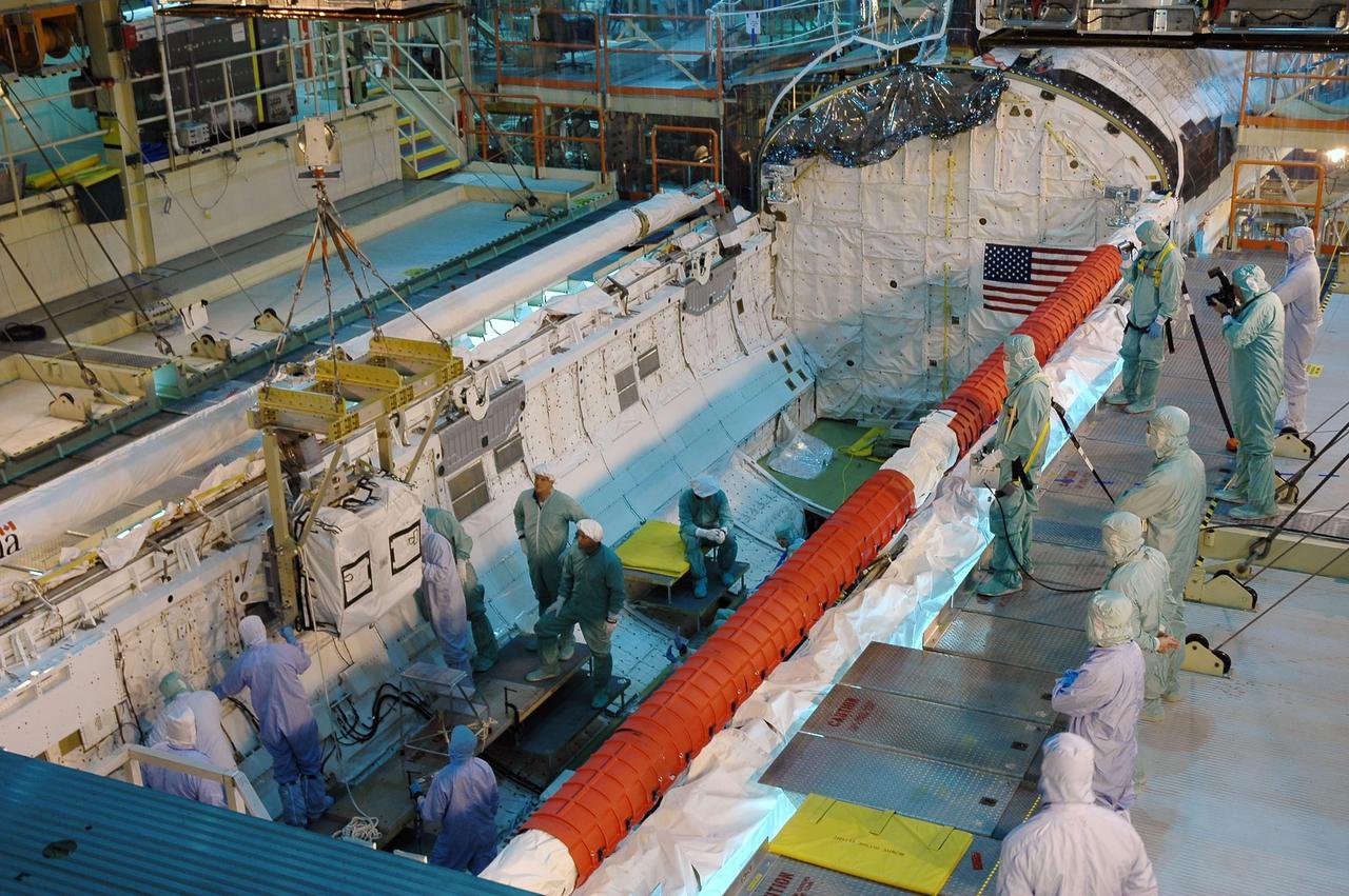
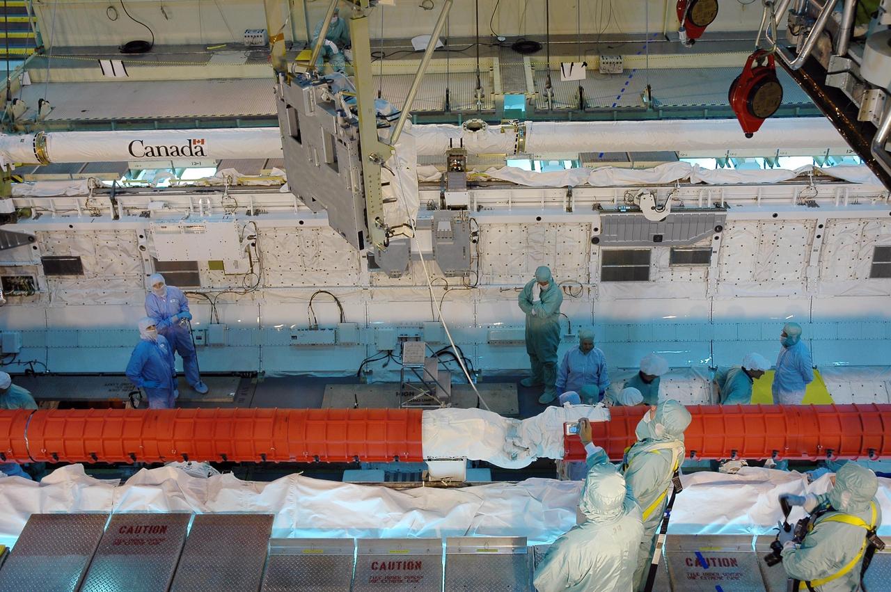
KENNEDY SPACE CENTER, FLA. - In the electrical engineering lab of the SRB Assembly and Refurbishment Facility, STS-114 crew members look at a DAS (data acquisition system) unit and some of the different circuit boards that will help drive the cameras on future flights and different cameras. In the foreground are Mission Specialists Soichi Noguchi, Stephen Robinson and Andrew Thomas. In the background (center, left to right) are Pilot James Kelly; Mission Specialists Charles Camarda and Wendy Lawrence; plus astronaut Steven Frick, who joined the STS-114 crew during equipment familiarization at KSC. The STS-114 mission is Logistics Flight 1, which is scheduled to deliver supplies and equipment, plus the external stowage platform, to the International Space Station.
KENNEDY SPACE CENTER, FLA. -- At Launch Pad 39A, a team of external tank specialists from Lockheed Martin and the United Space Alliance undertakes the task of removing the hydrogen feed-through connector in support of space shuttle Atlantis' STS-122 mission. Here, technicians set up equipment that will be used to take X-rays of the connector cable. Some of the tank's engine cutoff sensors, or ECO sensors, failed during propellant tanking for launch attempts on Dec. 6 and Dec. 9. Results of a tanking test on Dec. 18 pointed to an open circuit in the feed-through connector wiring, which is located at the base of the tank. The feed-through connector passes the wires from the inside of the tank to the outside. After the data from additional testing on the connector is analyzed, shuttle program managers will decide on a forward plan. Launch of STS-122 is targeted for January 2008. Photo credit: NASA/George Shelton
KENNEDY SPACE CENTER, FLA. -- On Launch Pad 39A at NASA's Kennedy Space Center, a technician completes installing the cover over the engine cutoff, or ECO, sensor system connector and wiring on space shuttle Atlantis' external tank. The feed-through connector passes the wires from the inside of the tank to the outside. Results of a tanking test on Dec. 18 pointed to an open circuit in the feed-through connector wiring, which is located at the base of the tank. The pins in the replacement connector were precisely soldered to create a connection that allows sensors inside the tank to send signals to the computers onboard Atlantis. The launch date for the shuttle's STS-122 mission has now been targeted for Feb. 7. Photo credit: NASA/Kim Shiflett
KENNEDY SPACE CENTER, FLA. -- KSC workers stand inside the payload bay of the orbiter Columbia following completion of electrical wiring inspections. At right, behind and below them is the cable tray with the wiring. During launch of Columbia on mission STS-93, a damaged wire caused a short circuit in two separate main engine controllers. As a result of the findings, Shuttle program managers decided to conduct inspections of the wiring in Endeavour's payload bay before its next mission, STS-99. The inspection and possible repair work will lead to a delayed launch date no earlier than Oct.7. The primary payload of the mission is the Shuttle Radar Topography Mission, a specially modified radar system that will gather data for the most accurate and complete topographic map of the Earth's surface that has ever been assembled
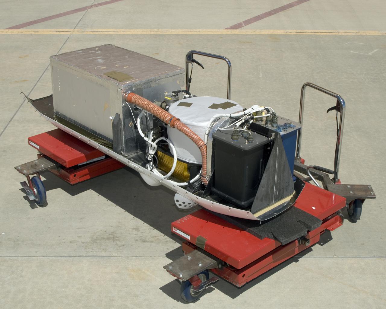
The instruments that make up the Ames Autonomous Module Scanner (AMS) that provided precise thermal-infrared imaging during the Western States Fire Mission in 2007 are detailed in this photo of the AMS as mounted on Ikhana's pod tray. The large foil-covered foam-insulated box at left covers the pressure vessel containing the data system computers and other electronics. The round white-topped assembly is the scan head, including the scan mirror, folded telescope, blackbody references, spectrometer and detectors. Two pressure boxes visible at the forward end of the tray contain the Applanix POS/AV precision navigation subsystem (black) and the power distributor including circuit breakers and ancillary wiring, scan motor controller and the blackbody reference temperature controller (blue).

STS057-30-021 (21 June-1 July 1993) --- Astronaut Brian Duffy, pilot, handles a soldering tool onboard the Earth-orbiting Space Shuttle Endeavour. The Soldering Experiment (SE) called for a crew member to solder on a printed circuit board containing 45 connection points, then de-solder 35 points on a similar board. The SE was part of a larger project called the Tools and Diagnostic Systems (TDS), sponsored by the Space and Life Sciences Directorate at Johnson Space Center (JSC). TDS represents a group of equipment selected from the tools and diagnostic hardware to be supported by the International Space Station program. TDS was designed to demonstrate the maintenance of experiment hardware on-orbit and to evaluate the adequacy of its design and the crew interface. Duffy and five other NASA astronauts spent almost ten days aboard the Space Shuttle Endeavour in Earth-orbit supporting the SpaceHab mission, retrieving the European Retrievable Carrier (EURECA) and conducting various experiments.
KENNEDY SPACE CENTER, FLA. -- On Launch Pad 39A at NASA's Kennedy Space Center, technicians prepare the cover to be installed over the engine cutoff, or ECO, sensor system connector and wiring on space shuttle space shuttle Atlantis' external tank. The feed-through connector passes the wires from the inside of the tank to the outside. Results of a tanking test on Dec. 18 pointed to an open circuit in the feed-through connector wiring, which is located at the base of the tank. The pins in the replacement connector were precisely soldered to create a connection that allows sensors inside the tank to send signals to the computers onboard Atlantis. The launch date for the shuttle's STS-122 mission has now been targeted for Feb. 7. Photo credit: NASA/Kim Shiflett
KENNEDY SPACE CENTER, FLA. -- Lloyd Johns, with Lockheed Martin, attaches the replacement feed-through connector in the engine cutoff, or ECO, sensor system to the internal connector on space shuttle Atlantis' external tank. The feed-through connector passes the wires from the inside of the tank to the outside. Results of a tanking test on Dec. 18 pointed to an open circuit in the feed-through connector wiring, which is located at the base of the tank. The pins in the replacement connector have been precisely soldered to create a connection that allows sensors inside the tank to send signals to the computers onboard Atlantis. The work is being done on Launch Pad 39A. Space shuttle Atlantis is now targeted for launch on Feb. 7. Photo credit: NASA/George Shelton