Jupiter Inner Satellites and Ring Components
Dr. Jennifer Williams, a NASA research chemical engineer, is inside the Prototype Development Laboratory at NASA’s Kennedy Space Center in Florida to begin testing on the Plasma Rapid Oxidation Technique for Extending Component Tenability (PROTECT) project on Nov. 2, 2022. Plasma electrolytic oxidation is a surface coating technology that produces oxide layers on the surface of light metals and their alloys to improve their performance characteristics. These coatings are tailored to provide a combination of characteristics such as corrosion protection, wear resistance, thermal management, extreme hardness, and fatigue performance. PROTECT is expected to demonstrate a 10 percent improved fatigue performance and a 70 percent improvement in corrosion characteristics on the interior of treated 3-D printed metallic parts when compared to non-treated parts. PROTECT could be applied to spacecraft and launch vehicles.
Plasma Rapid Oxidation Technique for Extending Component Tenabil
Dr. Jennifer Williams, a NASA research chemical engineer, displays two fatigue samples that will be tested  in the Plasma Rapid Oxidation Technique for Extending Component Tenability (PROTECT) experiments  inside the Prototype Laboratory at NASA’s Kennedy Space Center in Florida on Nov. 2, 2022. Plasma electrolytic oxidation is a surface coating technology that produces oxide layers on the surface of light metals and their alloys to improve their performance characteristics. These  coatings are tailored to provide a combination of characteristics such as corrosion protection, wear resistance, thermal management, extreme hardness, and fatigue performance. PROTECT is expected to demonstrate a 10 percent improved fatigue performance and a 70 percent improvement in corrosion characteristics on the interior of treated 3-D printed metallic parts when compared to non-treated parts. PROTECT could be applied to spacecraft and launch vehicles.
Plasma Rapid Oxidation Technique for Extending Component Tenabil
Gerard Moscoso, a mechanical engineer technician with NASA, handles a sample that is being prepared for fatigue and corrosion testing for the Plasma Rapid Oxidation Technique for Extending Component Tenability (PROTECT) project inside the Prototype Development Laboratory at NASA’s Kennedy Space Center in Florida on Nov. 2, 2022. Plasma electrolytic oxidation is a surface coating technology that produces oxide layers on the surface of light metals and their alloys to improve their performance characteristics. These coatings are tailored to provide a combination of characteristics such as corrosion protection, wear resistance, thermal management, extreme hardness, and fatigue performance. PROTECT is expected to demonstrate a ten percent improved fatigue performance and a 70 percent improvement in corrosion characteristics on the interior of treated 3-D printed metallic parts when compared to non-treated parts. PROTECT could be applied on spacecraft and launch vehicles.
Plasma Rapid Oxidation Technique for Extending Component Tenabil
Testing of the Plasma Rapid Oxidation Technique for Extending Component Tenability (PROTECT) experiment is underway inside the Prototype Development Laboratory at NASA’s Kennedy Space Center in Florida on Nov. 2, 2022. Plasma electrolytic oxidation is a surface coating technology that produces oxide layers on the surface of light metals and their alloys to improve their performance characteristics. These  coatings are tailored to provide a combination of characteristics such as corrosion protection, wear resistance, thermal management, extreme hardness, and fatigue performance. PROTECT is expected to demonstrate a ten percent improved fatigue performance and a 70 percent improvement in corrosion characteristics on the interior of treated 3-D printed metallic parts when compared to non-treated parts. PROTECT could be applied on spacecraft and launch vehicles.
Plasma Rapid Oxidation Technique for Extending Component Tenabil
Gerard Moscoso, a mechanical engineer technician with NASA, prepares the Plasma Rapid Oxidation Technique for Extending Component Tenability (PROTECT) specimens for testing inside the Prototype Development Laboratory at NASA’s Kennedy Space Center in Florida on Nov. 2, 2022. Plasma electrolytic oxidation is a surface coating technology that produces oxide layers on the surface of light metals and their alloys to improve their performance characteristics. These coatings are tailored to provide a combination of characteristics such as corrosion protection, wear resistance, thermal management, extreme hardness, and fatigue performance. PROTECT is expected to demonstrate a 10 percent improved fatigue performance and a 70 percent improvement in corrosion characteristics on the interior of treated 3-D printed metallic parts when compared to non-treated parts. PROTECT could be applied on spacecraft and launch vehicles.
Plasma Rapid Oxidation Technique for Extending Component Tenabil
Gerard Moscoso, a mechanical engineer technician with NASA, prepares a sample for testing for the  Plasma Rapid Oxidation Technique for Extending Component Tenability (PROTECT) project inside the Prototype Development Laboratory at NASA’s Kennedy Space Center in Florida on Nov. 2, 2022. Plasma electrolytic oxidation is a surface coating technology that produces oxide layers on the surface of light metals and their alloys to improve their performance characteristics. These coatings are tailored to provide a combination of characteristics such as corrosion protection, wear resistance, thermal management, extreme hardness, and fatigue performance. PROTECT is expected to demonstrate a 10 percent improved fatigue performance and a 70 percent improvement in corrosion characteristics on the interior of treated 3-D printed metallic parts when compared to non-treated parts. PROTECT could be applied on spacecraft and launch vehicles.
Plasma Rapid Oxidation Technique for Extending Component Tenabil
From left, Dr. Jennifer Williams, a NASA research chemical engineer, and Gerard Moscoso, a mechanical engineer technician, inspect specimens prepared forthe Plasma Rapid Oxidation Technique for Extending Component Tenability (PROTECT) experiment inside the Prototype Development Laboratory at NASA’s Kennedy Space Center in Florida on Nov. 2, 2022. Plasma electrolytic oxidation is a surface coating technology that produces oxide layers on the surface of light metals and their alloys to improve their performance characteristics. These coatings are tailored to provide a combination of characteristics such as corrosion protection, wear resistance, thermal management, extreme hardness, and fatigue performance. PROTECT is expected to demonstrate a 10 percent improved fatigue performance and a 70 percent improvement in corrosion characteristics on the interior of treated 3-D printed metallic parts when compared to non-treated parts. PROTECT could be applied used on spacecraft and launch vehicles.
Plasma Rapid Oxidation Technique for Extending Component Tenabil
Testing of the Plasma Rapid Oxidation Technique for Extending Component Tenability (PROTECT) experiment is underway inside the Prototype Development Laboratory at NASA’s Kennedy Space Center in Florida on Nov. 2, 2022. Plasma electrolytic oxidation is a surface coating technology that produces oxide layers on the surface of light metals and their alloys to improve their performance characteristics. These coatings are tailored to provide a combination of characteristics such as corrosion protection, wear resistance, thermal management, extreme hardness, and fatigue performance. PROTECT is expected to demonstrate a 10 percent improved fatigue performance and a 70 percent improvement in corrosion characteristics on the interior of treated 3-D printed metallic parts when compared to non-treated parts. PROTECT could be applied on spacecraft and launch vehicles.
Plasma Rapid Oxidation Technique for Extending Component Tenabil
This cutaway drawing illustrates major Skylab components in launch configuration on top of the Saturn V. In an early effort to extend the use of Apollo for further applications, NASA established the Apollo Applications Program (AAP) in August of 1965. The AAP was to include long duration Earth orbital missions during which astronauts would carry out scientific, technological, and engineering experiments in space by utilizing modified Saturn launch vehicles and the Apollo spacecraft. Established in 1970, the Skylab Program was the forerurner of the AAP. The goals of the Skylab were to enrich our scientific knowledge of the Earth, the Sun, the stars, and cosmic space; to study the effects of weightlessness on living organisms, including man; to study the effects of the processing and manufacturing of materials utilizing the absence of gravity; and to conduct Earth resource observations. The Skylab also conducted 19 selected experiments submitted by high school students. Skylab's 3 different 3-man crews spent up to 84 days in Earth orbit. The Marshall Space Flight Center (MSFC) had responsibility for developing and integrating most of the major components of the Skylab: the Orbital Workshop (OWS), Airlock Module (AM), Multiple Docking Adapter (MDA), Apollo Telescope Mount (ATM), Payload Shroud (PS), and most of the experiments. MSFC was also responsible for providing the Saturn IB launch vehicles for three Apollo spacecraft and crews and a Saturn V launch vehicle for the Skylab.
Skylab
The Plasma Spray-Physical Vapor Deposition (PS-PVD) Rig at NASA Glenn Research Center. The rig helps develop coatings for next-generation aircraft turbine components and create more efficient engines.
Vapor Deposition Rig
This image shows major components of NASA's Mars 2020 mission in the High Bay 1 clean room in JPL's Spacecraft Assembly Facility.  Movie available at https://photojournal.jpl.nasa.gov/catalog/PIA23164
Mars 2020 Components in High Bay
An illustration of MOXIE (Mars Oxygen ISRU Experiment) and its components. An air pump pulls in carbon dioxide gas from the Martian atmosphere, which is then regulated and fed to the Solid OXide Electrolyzer (SOXE), where it is electrochemically split to produce pure oxygen.  https://photojournal.jpl.nasa.gov/catalog/PIA24177
Components of MOXIE (Illustration)
Stennis Space Center employees install the J-2X powerpack Dec. 5 in preparation for testing of the component, beginning in early 2012. The J-2X rocket engine is being developed as part of NASA's new Space Launch System.
J-2X engine
The NISAR (NASA-ISRO Synthetic Aperture Radar) satellite sits in a clean room facility at U R Rao Satellite Centre (URSC) in Bengaluru, India, in mid-June 2023, shortly after engineers from NASA's Jet Propulsion Laboratory in Southern California and the Indian Space Research Organisation joined its two main components, the radar instrument payload and the spacecraft bus.  Set to launch in early 2024 from the Satish Dhawan Space Centre in Sriharikota, India, NISAR is being jointly developed by NASA and ISRO to observe movements of Earth's land and ice surfaces in extremely fine detail. As NISAR observes nearly every part of Earth at least once every 12 days, the satellite will help scientists understand, among other observables, the dynamics of forests, wetlands, and agricultural lands.  The radar instrument payload, partially wrapped in gold-colored thermal blanketing, arrived from JPL in March and consists of L- and S-band radar systems, so named to indicate the wavelengths of their signals. Both sensors can see through clouds and collect data day and night. The bus, which is shown in blue blanketing and includes components and systems developed by both ISRO and JPL, was built at URSC and will provide power, navigation, pointing control, and communications for the mission.  NISAR is an equal collaboration between NASA and ISRO and marks the first time the two agencies have cooperated on hardware development for an Earth-observing mission. JPL, which is managed for NASA by Caltech in Pasadena, leads the U.S. component of the project and is providing the mission's L-band SAR. NASA is also providing the radar reflector antenna, the deployable boom, a high-rate communication subsystem for science data, GPS receivers, a solid-state recorder, and payload data subsystem. URSC, which is leading the ISRO component of the mission, is providing the spacecraft bus, the S-band SAR electronics, the launch vehicle, and associated launch services and satellite mission operations.  https://photojournal.jpl.nasa.gov/catalog/PIA25865
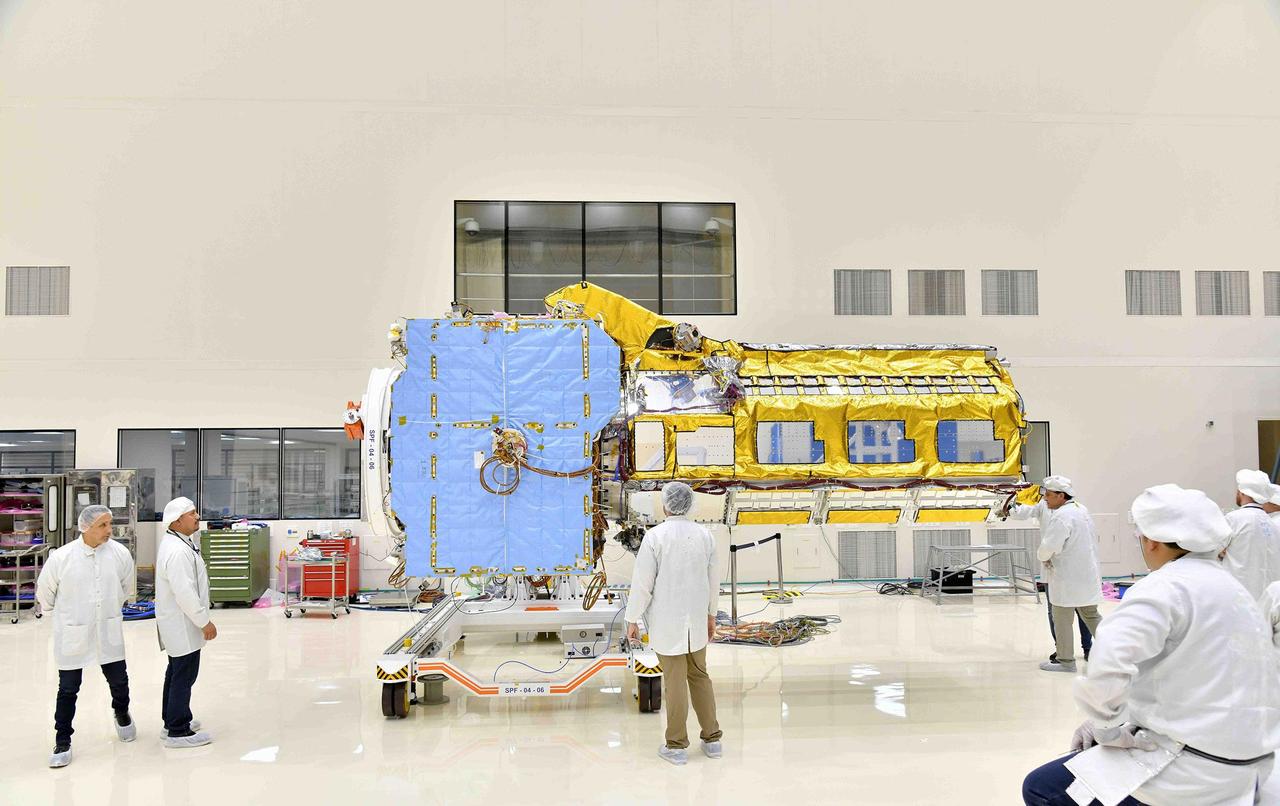
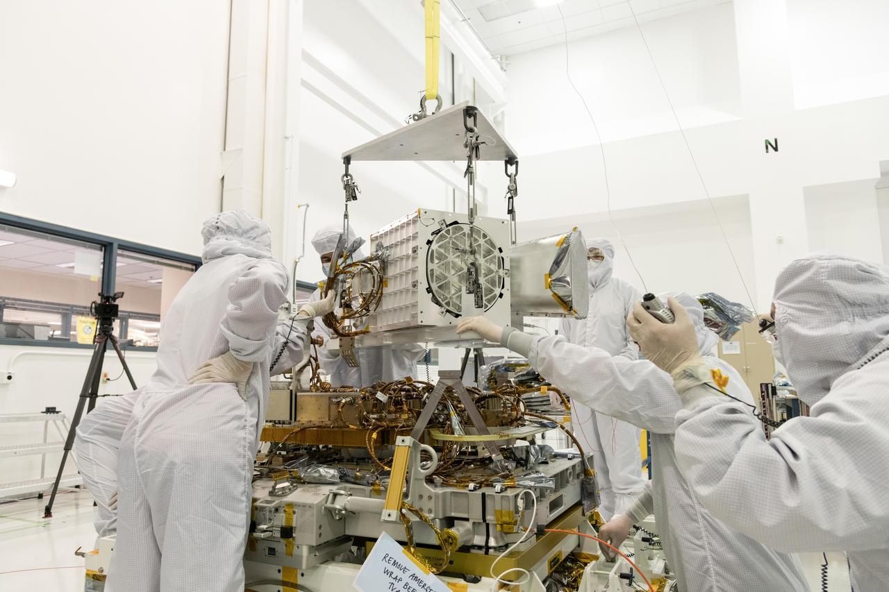
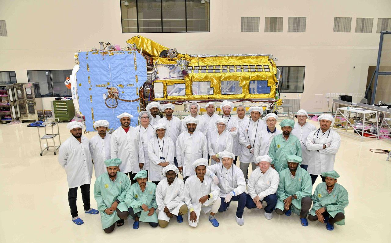
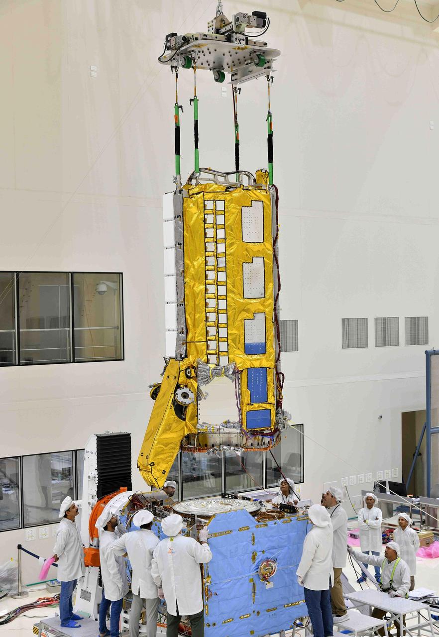
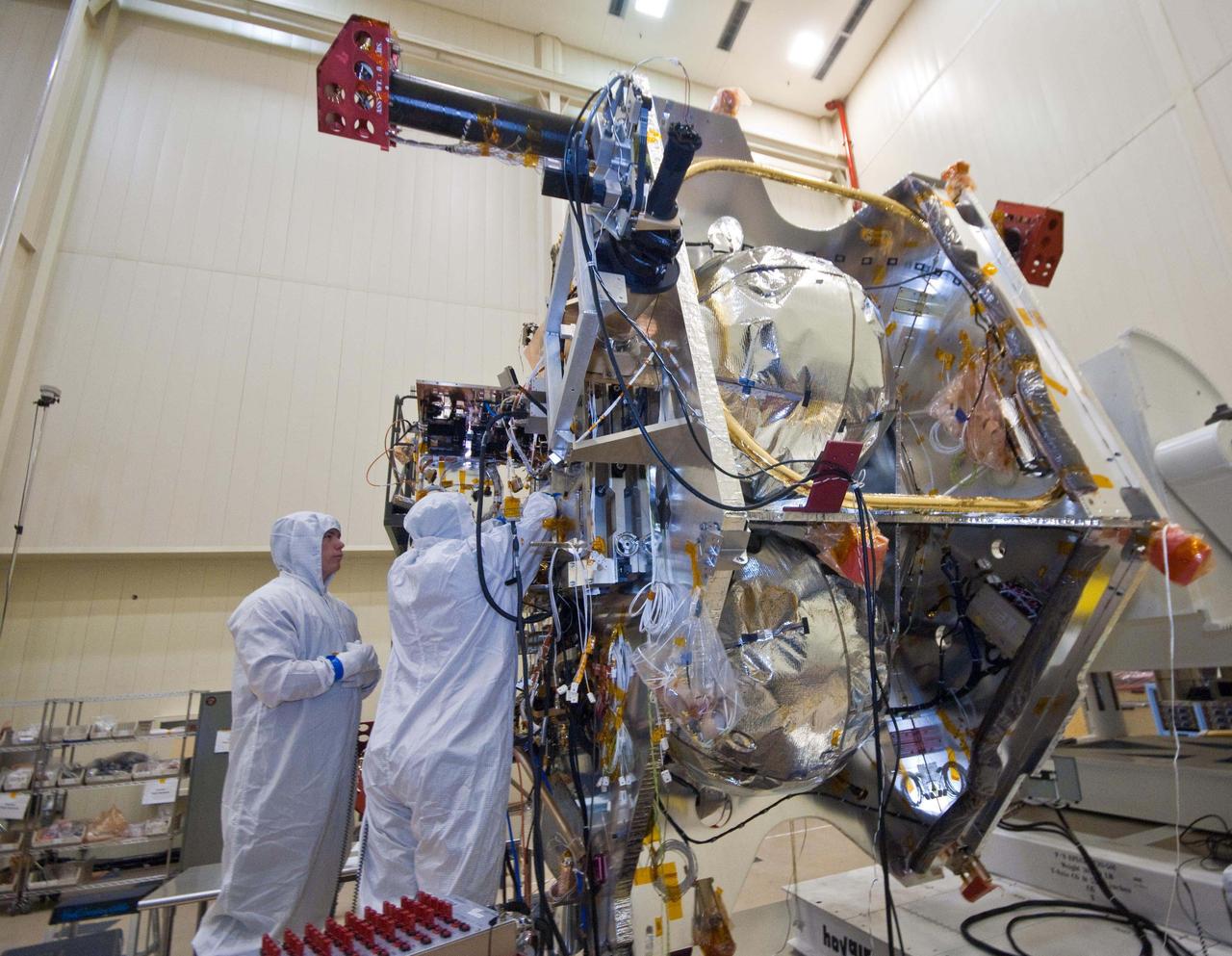
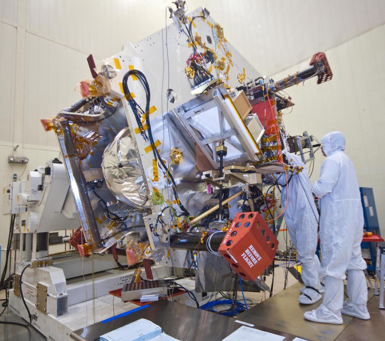
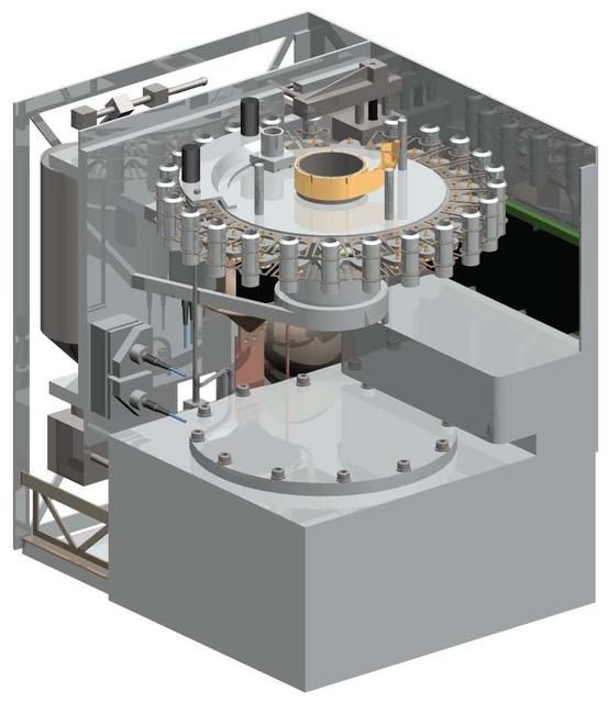
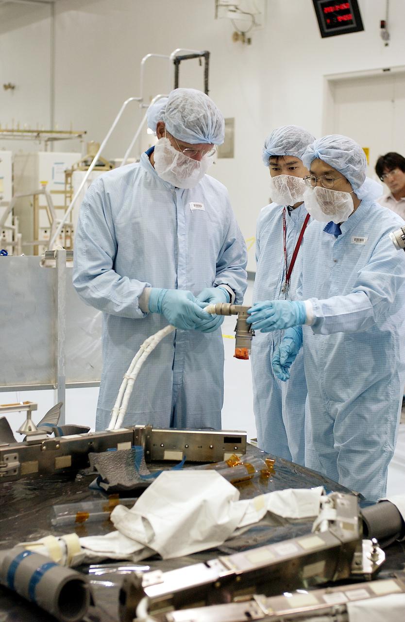
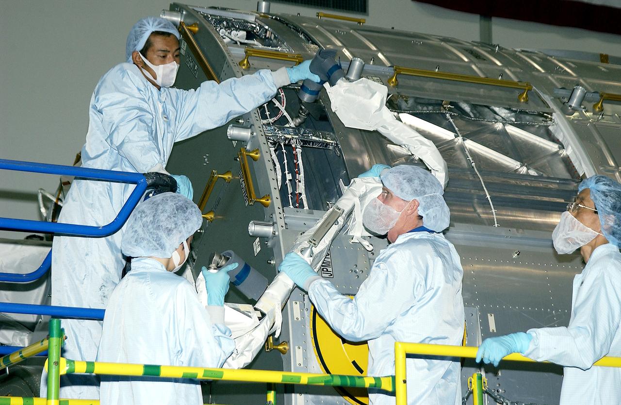
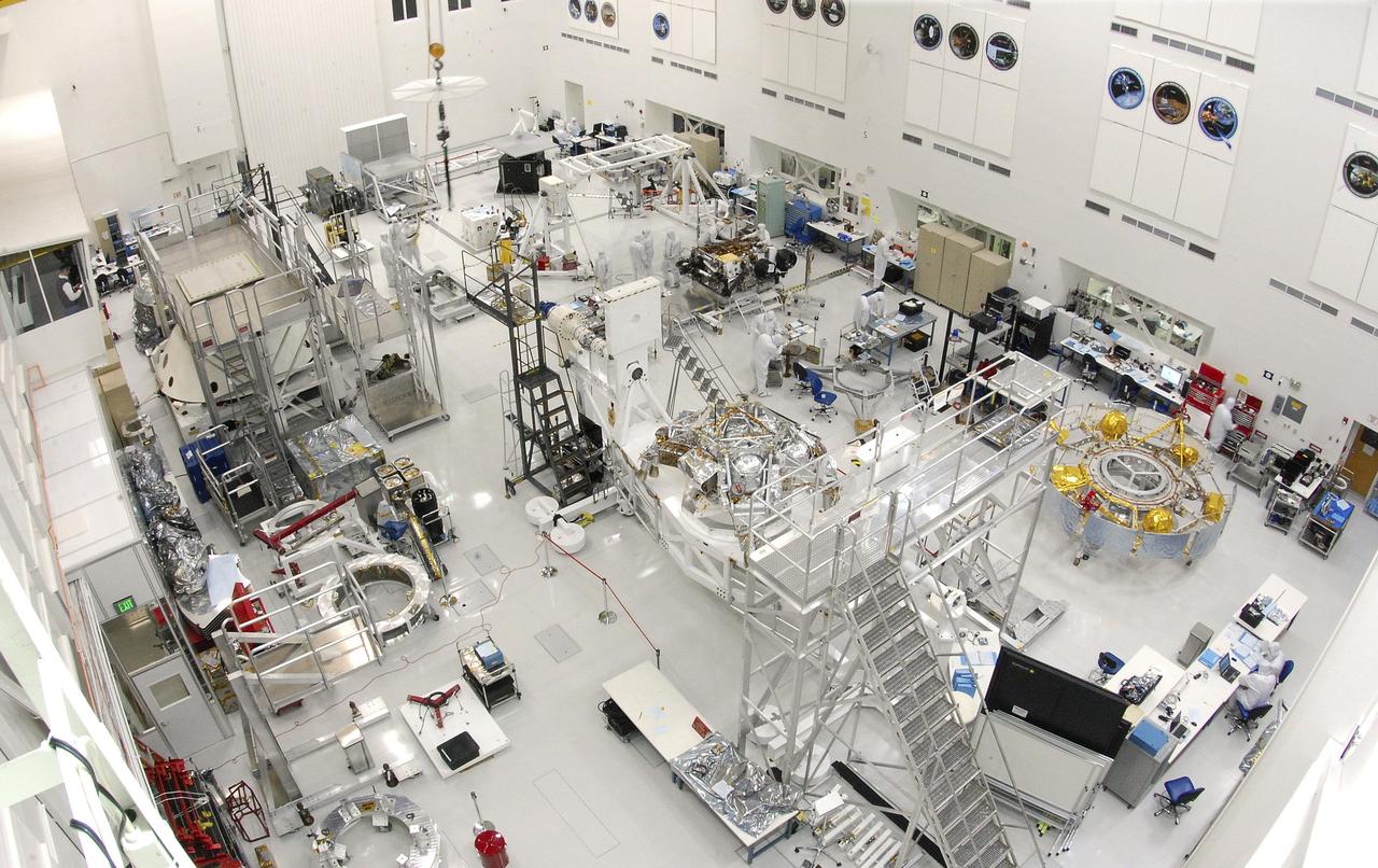
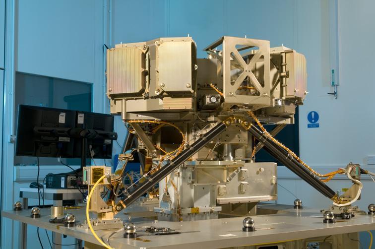
Main Components of NISAR Satellite Joined
Engineers and technicians at NASA's Jet Propulsion Laboratory in Southern California assemble components of the Earth Surface Mineral Dust Source Investigation (EMIT) mission instrument in December 2021. The upper portion consists of EMIT's optical subsystem, including a telescope and imaging spectrometer, while the baseplate below holds electronics.  EMIT will collect measurements of 10 important surface minerals – hematite, goethite, illite, vermiculite, calcite, dolomite, montmorillonite, kaolinite, chlorite, and gypsum – in arid regions between 50-degree south and north latitudes in Africa, Asia, North and South America, and Australia. The data EMIT collects will help scientists better understand the role of airborne dust particles in heating and cooling Earth's atmosphere on global and regional scales.  https://photojournal.jpl.nasa.gov/catalog/PIA25146
EMIT's Components Come Together at JPL
NASA Administrator Bridenstine talks with Armstrong's Larry Hudson about the capabilities of the Flight Loads Lab to conduct mechanical-load and thermal studies of structural components and complete flight vehicles.
NASA Administrator Bridenstine is inside Armstrong Flight Research Center's Flight Loads Lab, which is capable of conducting mechanical-load and thermal studies of structural components and complete flight vehicles.
Mike Ressler right and Kalyani Sukhatme of NASA JPL pose in the clean room with a model component, called a focal plane module, of the Mid-Infrared Instrument on NASA James Webb Space Telescope.
Shake, Rattle and Roll: James Webb Telescope Components Pass Tests
iss072e629219 (Feb. 19, 2025) --- NASA astronaut and Expedition Flight Engineer Butch Wilmore replaces components on a spacesuit inside the International Space Station's Quest airlock.
Astronaut Butch Wilmore replaces components on a spacesuit
S61-02733 (28 July 1961) --- Table top view of some of the Mercury suit components including gloves, boots and helmet. Photo credit: NASA
SUIT - MERCURY-3 (MR-3) - GLOVES - COMPONENTS
Clark Johnson inspects components tested in the Environmental Laboratory at NASA’s Armstrong Flight Research Center in California. He ensures none of the research items were damaged during testing and a check to see that the workmanship standards for the components are met.
NASA Armstrong Assists with Orion AA-2 Component Testing
April Torres and Kyle Dauk set up for a thermal test of components in the Environmental Laboratory at NASA’s Armstrong Flight Research Center in California. The components are part of the center’s work on the Orion AA-2 vehicle that is scheduled for a flight test in 2019.
NASA Armstrong Assists with Orion AA-2 Component Testing
Martin Munday selects the accelerometers that will be used for vibration testing of the Orion AA-2 test article components in the Environmental Laboratory at NASA’s Armstrong Flight Research Center in California. Following Armstrong’s validation and verification work, the components will be integrated on the AA-2 test article for a flight set for 2019.
NASA Armstrong Assists with Orion AA-2 Component Testing
iss069e006030 (April 28, 2023) --- Four main components on the Roscosmos segment of the International Space Station are pictured as the orbital outpost soared 261 miles above the north Atlantic Ocean. From top to bottom, are the Nauka multipurpose laboratory module, the European robotic arm attached to Nauka, the Prichal docking module, and the Soyuz MS-23 crew ship.
Roscosmos components on the International Space Station
A team of engineers and technicians from the Indian Space Research Organisation and NASA's Jet Propulsion Laboratory in Southern California pose in June at ISRO's U R Rao Satellite Centre (URSC) in Bengaluru, India, after working together to combine the two main components of the NISAR (NASA-ISRO Synthetic Aperture Radar) satellite.  Set to launch in early 2024 from the Satish Dhawan Space Centre in Sriharikota, India, NISAR is being jointly developed by NASA and ISRO to observe movements of Earth's land and ice surfaces in extremely fine detail. As NISAR observes nearly every part of Earth at least once every 12 days, the satellite will help scientists understand, among other observables, the dynamics of forests, wetlands, and agricultural lands.  The radar instrument payload, partially wrapped in gold-colored thermal blanketing, arrived from JPL in March and consists of L- and S-band radar systems, so named to indicate the wavelengths of their signals. Both sensors can see through clouds and collect data day and night. The bus, which is shown in blue blanketing and includes components and systems developed by both ISRO and JPL, was built at URSC and will provide power, navigation, pointing control, and communications for the mission. The team combined the payload and the bus with the help of a crane.  NISAR is an equal collaboration between NASA and ISRO and marks the first time the two agencies have cooperated on hardware development for an Earth-observing mission. JPL, which is managed for NASA by Caltech in Pasadena, leads the U.S. component of the project and is providing the mission's L-band SAR. NASA is also providing the radar reflector antenna, the deployable boom, a high-rate communication subsystem for science data, GPS receivers, a solid-state recorder, and payload data subsystem. URSC, which is leading the ISRO component of the mission, is providing the spacecraft bus, the S-band SAR electronics, the launch vehicle, and associated launch services and satellite mission operations.  https://photojournal.jpl.nasa.gov/catalog/PIA25867
U.S.-Indian Team Collaborates to Assemble Main Components of NISAR
iss069e003171 (April 13, 2023) --- Three Roscosmos components on the International Space Station were photographed by UAE (United Arab Emirates) astronaut and Expedition 69 Flight Engineer Sultan Alneyadi while orbiting 263 miles above a partly cloudy northern Europe. At left, from top to bottom, are the Nauka multipurpose laboratory module's forward port, the Prichal docking module, and the Soyuz MS-23 crew ship.
Three Roscosmos components on the International Space Station
Various Components of Goodyear Inflatable Airplane in Full Scale Tunnel building 643 Test 238
Various Components of Goodyear Inflatable Airplane in Full Scale Tunnel
Various Components of Goodyear Inflatable Airplane in Full Scale Tunnel building 643 Test 238
Various Components of Goodyear Inflatable Airplane in Full Scale Tunnel
Various Components of Goodyear Inflatable Airplane in Full Scale Tunnel building 643 Test 238
Various Components of Goodyear Inflatable Airplane in Full Scale Tunnel
Engineers from NASA's Jet Propulsion Laboratory in Southern California and the Indian Space Research Organisation (ISRO), working in a clean room facility at ISRO's U R Rao Satellite Centre (URSC) in Bengaluru, India, in mid-June 2023, use a crane to align the radar instrument payload for the NISAR (NASA-ISRO Synthetic Aperture Radar) mission above the satellite's spacecraft bus so that the two components can be combined.  Set to launch in early 2024 from the Satish Dhawan Space Centre in Sriharikota, India, NISAR is being jointly developed by NASA and ISRO to observe movements of Earth's land and ice surfaces in extremely fine detail. As NISAR observes nearly every part of Earth at least once every 12 days, the satellite will help scientists understand, among other observables, the dynamics of forests, wetlands, and agricultural lands.  The radar instrument payload, partially wrapped in gold-colored thermal blanketing, arrived from JPL in March and consists of L- and S-band radar systems, so named to indicate the wavelengths of their signals. Both sensors can see through clouds and collect data day and night. The bus, which is shown in blue blanketing and includes components and systems developed by both ISRO and JPL, was built at URSC and will provide power, navigation, pointing control, and communications for the mission.  NISAR is an equal collaboration between NASA and ISRO and marks the first time the two agencies have cooperated on hardware development for an Earth-observing mission. JPL, which is managed for NASA by Caltech in Pasadena, leads the U.S. component of the project and is providing the mission's L-band SAR. NASA is also providing the radar reflector antenna, the deployable boom, a high-rate communication subsystem for science data, GPS receivers, a solid-state recorder, and payload data subsystem. URSC, which is leading the ISRO component of the mission, is providing the spacecraft bus, the S-band SAR electronics, the launch vehicle, and associated launch services and satellite mission operations.  https://photojournal.jpl.nasa.gov/catalog/PIA25866
NISAR Satellite's Major Components Come Together
Line drawings illustrate the front and back of the space shuttle launch and entry suit (LES) and labels identify various components. LES was designed for STS-26, the return to flight mission, and subsequent missions. Included in the crew escape system (CES) package are launch and entry helmet (LEH) with communications carrier (COMM CAP), parachute pack and harness, life preserver unit (LPU), life raft unit (LRU), LES gloves, suit oxygen manifold and valves, boots, and survival gear. Details of larger components are also identified.
Labeled line drawing of launch and entry suit identifies various components
iss069e009909 (May 9, 2023) --- NASA astronaut and Expedition 69 Flight Engineer Woody Hoburg works inside the International Space Station's Destiny laboratory module and replaces life support system components.
Astronaut Woody Hoburg replaces life support system components
iss072e403385 (Dec. 24, 2024) --- NASA astronaut and Expedition 72 Commander Suni Williams checks research components inside the Kibo laboratory module's Advanced Plant Habitat aboard the International Space Station.
Astronaut Suni Williams checks research components inside the Kibo laboratory module
AS11-37-5551 (20 July 1969) --- Two components of the Early Apollo Scientific Experiments Package (EASEP) are seen deployed on the lunar surface in this view photographed from inside the Lunar Module (LM).  In the far background is the Passive Seismic Experiment Package (PSEP); and to the right and closer to the camera is the Laser Ranging Retro-Reflector (LR-3).  The footprints of Apollo 11 astronauts Neil A. Armstrong and Edwin E. Aldrin Jr. are very distinct in the lunar soil.
Components of the Early Apollo Scientific Experiments Package (EASEP)
iss071e414661 (Aug. 1, 2024) --- NASA astronaut and Expedition 71 Flight Engineer Tracy C. Dyson services research components inside the Solid Combustion Experiment Module (SCEM) aboard in the Interational Space Station's Kibo laboratory module. The SCEM enables combustion research in microgravity to study how materials burn in weightlessness and improve fire safety techniques aboard spacecraft.
NASA astronaut Tracy C. Dyson services combustion research components
iss073e0118757 (May 29, 2025) --- NASA astronaut and Expedition 73 Flight Engineer Nichole Ayers cleans and services life support components that are part of the Oxygen Generation System rack located inside the International Space Station's Destiny laboratory module.
NASA astronaut Nichole Ayers cleans and services life support components
iss073e0136234 (June 9, 2025) --- NASA astronaut and Expedition 73 Flight Engineer Jonny Kim replaces orbital plumbing components inside the International Space Station's restroom, also called the waste and hygiene compartment, located in the Tranquility module.
NASA astronaut Jonny Kim replaces orbital plumbing components
Angelo De La Rosa works inside the Environmental Laboratory’s thermal chamber to attach test articles to the testing architecture at NASA’s Armstrong Flight Research Center in California. The center is testing components for integration into the Orion AA-2 test article scheduled for a test flight of the launch abort system in 2019.
NASA Armstrong Assists with Orion AA-2 Component Testing
Astronauts Jerry L. Ross (right) and Sherwood C. (Woody) Spring (left) share a foot restraint as they survey the assembled ACCESS components after a lengthy extravehicular activity. Both men salute the American flag placed on the assembled ACCESS tower. Stowed EASE pieces are reflected in the window through which the photo was taken.
Astronauts Jerry Ross and Sherwood Spring survey assembled ACCESS components
iss073e0257842 (July 8, 2025) --- Roscosmos cosmonauts (from left) Sergey Ryzhikov and Alexey Zubritsky, both Expedition 73 flight engineers, join each other and photograph treadmill components for inspection inside the International Space Station's Zvezda service module. Credit: Roscosmos
Roscosmos cosmonauts Sergey Ryzhikov and Alexey Zubritsky inspect treadmill components
This illustration depicts five major components of the Mars 2020 spacecraft. Top to bottom: cruise stage, backshell, descent stage, Perseverance rover and heat shield. The various components perform critical roles during the vehicle's cruise to Mars and its dramatic entry, descent, and landing.  https://photojournal.jpl.nasa.gov/catalog/PIA24128
Mars 2020 Expanded Spacecraft Illustration
Technicians install components that will aid with guidance, navigation and control of NASA Juno spacecraft.
Building Juno Electronic Brain
This diagram shows components of the investigations payload for NASA Mars 2020 rover mission.
Payload for NASA Mars 2020 Rover
Technicians install components that will aid with guidance, navigation and control of NASA Juno spacecraft. Like most of Juno sensitive electronics, these components are situated within the spacecraft titanium radiation vault.
Installing Electronics in Juno Vault
Illustration of one of the twin MarCO spacecraft with some key components labeled. Front cover is left out to show some internal components. Antennas and solar arrays are in deployed configuration.  https://photojournal.jpl.nasa.gov/catalog/PIA22548
Mars Cube One in Detail
The Central Processing System at Glenn Research Center controls operations in the wind tunnels, propulsion systems lab, engine components research lab, and compressor, turbine and combustor test cells. Documentation photos of the facility were taken on December 19, 2023. Photo Credit: (NASA/Sara Lowthian-Hanna)
Central Process System Interior Photos
iss072e629194 (Feb. 18, 2025) --- NASA astronaut and Expedition 72 Flight Engineer Nick Hague works in a portable glovebag and cleans pumps, replaces components, and installs bio-ink syringes inside the BioFabrication Facility being tested for its capability to print biological, or organ-like, tissues in space and learn how to eventually fabricate human organs off the Earth.
Astronaut Nick Hague replaces components inside the BioFabrication Facility
AS14-67-9376 (5 Feb. 1971) --- Several components of the Apollo lunar surface experiments package (ASLEP) are deployed in this photograph taken during the first Apollo 14 extravehicular activity (EVA). The larger object with antenna is the ALSEP central station (CS). The active seismic experiment (ASE) mortar package assembly is to the rear left of the CS. The charged particle lunar environment experiment (CPLEE) is to the right rear of the CS. A portion of the modularized equipment transporter (MET) can be seen in the left foreground.
Components of the ALSEP deployed during Apollo 14 first EVA
iss072e629184 (Feb. 18, 2025) --- NASA astronaut and Expedition 72 Flight Engineer Nick Hague works in a portable glovebag and cleans pumps, replaces components, and installs bio-ink syringes inside the BioFabrication Facility being tested for its capability to print biological, or organ-like, tissues in space and learn how to eventually fabricate human organs off the Earth.
Astronaut Nick Hague replaces components inside the BioFabrication Facility
iss073e0118580 (May 27, 2025) --- NASA astronaut and Expedition 73 Flight Engineer Nichole Ayers replaces components on an experimental carbon dioxide removal device aboard the International Space Station. Also called the Thermal Amine Scrubber, the advanced life support mechanism is testing a new method that removes carbon dioxide from the station’s atmosphere and recovers water for oxygen generation.
Astronaut Nichole Ayers replaces components on an experimental carbon dioxide removal device
NASA GLENN/NASA LANGLEY LOADS COMPARISON TEST WITH 6 COMPONENT FORCE/MOMENT BALANCE AND 1.7% HIGH SPEED RESEARCH MODEL 5.
These photos show how teams at NASA’s Michoud Assembly Facility in New Orleans manufactured the Y-ring that will be used on the evolved Block 1B configuration of the SLS (Space Launch System) rocket. It is one of the first components that will make up a portion of the core stage that will power NASA’s Artemis V mission. The large metal ring will serve as the aft ring for the rocket’s liquid hydrogen tank.  The SLS core stage is the backbone of the SLS rocket, stretching 212 feet from top to bottom, and includes four RS-25 engines at its base. At launch, its two huge liquid propellant tanks provide more than 733,000 gallons of fuel to produce more than 2 million pounds of thrust. Michoud Assembly Facility and the SLS Program are managed by NASA’s Marshall Space Flight Center in Huntsville, Alabama. Image credit: NASA/Michael DeMocker
First Components of Artemis V SLS Rocket Manufactured at Michoud
Stennis Space Center engineers are preparing to conduct water tests on an updated version of the scissors duct component of the J-2X engine. Measuring about 2 feet long and about 8 inches in diameter, the duct on the J-2X predecessor, the J-2, connected its fuel turbo pumps to the flight vehicle's upper stage run tanks. According to NASA's J-2X project manager at SSC, Gary Benton, the water tests should establish the limits of the duct's ability to withstand vibration.
Scissors Duct
In this image the martian surface is completely hidden from view by thick  clouds. The thickness of the clouds indicates the dust is a major  component of the clouds
Where the Surface?
These are the components of the Desert Christian experiment launched to space Dec. 3 that could one day lead to fast-charging batteries.
ED15-0229-02
NASA Glenn/NASA Langley, Loads Comparison Test With 6 Component Force/Moment Balance and 1.7% High Speed Research, HSR Model 5. In the Glenn Research Center 10x10 Foot Supersonic Wind Tunnel, SWT
NASA Glenn/NASA Langley Loads Comparison Test with 6 Component Force/Moment Balance and 1.7% High Speed Research, HSR Model 5
NASA GLENN/NASA LANGLEY LOADS COMPARISON TEST WITH 6 COMPONENT FORCE/MOMENT BALANCE AND 1.7% HIGH SPEED RESEARCH MODEL 5. in the 10x10 super sonic wind tunnel
NASA GLENN/NASA LANGLEY LOADS COMPARISON TEST WITH 6 COMPONENT FORCE/MOMENT BALANCE AND 1.7% HIGH SPEED RESEARCH MODEL 5.
This is an image of the X-59 inlet with a safety covering. The inlet’s purpose is to adjust air speeds before they pass through the aircraft’s engine. The purpose of the covering is to protect the inlet and engine from foreign objects.
Critical Components - Forebody and Miscellaneous
iss073e0118793 (May 27, 2025) --- Astronauts Takuya Onishi of JAXA (Japan Aerospace Exploration Agency) and Nichole Ayers of NASA, Expedition 73 Commander and Flight Engineer respectively, replace components on an experimental carbon dioxide removal device aboard the International Space Station. Also called the Thermal Amine Scrubber, the advanced life support mechanism is testing a new method that removes carbon dioxide from the station’s atmosphere and recovers water for oxygen generation.
Astronauts Takuya Onishi and Nichole Ayers replace components on an experimental carbon dioxide removal device
iss073e0118813 (May 28, 2025) --- JAXA (Japan Aerospace Exploration Agency) astronaut and Expedition 73 Commander Takuya Onishi replaces components on an experimental carbon dioxide removal device aboard the International Space Station. Also called the Thermal Amine Scrubber, the advanced life support mechanism is testing a new method that removes carbon dioxide from the station’s atmosphere and recovers water for oxygen generation.
JAXA astronaut Takuya Onishi replaces components on an experimental carbon dioxide removal device
This illustration shows some of the components on and near the end of the robotic arm on NASA Phoenix Mars Lander. Primary and secondary blades on the scoop that aided in the collection of soil samples.
Working End of Robotic Arm on Phoenix
NASA Mars Exploration Rover Opportunity recorded the component images for this self-portrait about three weeks before completing a decade of work on Mars.
Self-Portrait by Opportunity Mars Rover in January 2014
This old crater in Terra Sabaea has patterned floor material that is indicative of having a volitile component. At high latitudes the volitile is most likely ice
Terra Sabaea
This mosaic from NASA Dawn spacecraft shows dark material near a series of craters known as the nowman on asteroid Vesta. That ejected material is a complex mixture of components.
Dark Materials at the Snowman
Some key components of a NASA-funded instrument being developed for the payload of the European Space Agency ExoMars mission stand out in thisillustration of the instrument
Urey: Mars Organic and Oxidant Detector
This image of NASA Curiosity rover shows the location of the two components of the Dynamic Albedo of Neutrons instrument. The neutron generator is mounted on the right hip and the detectors are on the opposite hip.
Location of DAN on Curiosity
KENNEDY SPACE CENTER, FLA. -  In the Space Station Processing Facility, STS-115 Mission Specialist Joseph Tanner (left)  checks out a camera and cables to be used in the Japanese Experiment Module (JEM). Known as Kibo, the JEM consists of six components: two research facilities - the Pressurized Module and the Exposed Facility; a Logistics Module attached to each of them; a Remote Manipulator System; and an Inter-Orbit Communication System unit. Kibo also has a scientific airlock through which experiments are transferred and exposed to the external environment of space. The various components of JEM will be assembled in space over the course of three Space Shuttle missions. Equipment familiarization is a routine part of astronaut training and launch preparations.
KENNEDY SPACE CENTER, FLA. - In the Space Station Processing Facility, STS-115 Mission Specialist Joseph Tanner (left) checks out a camera and cables to be used in the Japanese Experiment Module (JEM). Known as Kibo, the JEM consists of six components: two research facilities - the Pressurized Module and the Exposed Facility; a Logistics Module attached to each of them; a Remote Manipulator System; and an Inter-Orbit Communication System unit. Kibo also has a scientific airlock through which experiments are transferred and exposed to the external environment of space. The various components of JEM will be assembled in space over the course of three Space Shuttle missions. Equipment familiarization is a routine part of astronaut training and launch preparations.
KENNEDY SPACE CENTER, FLA. -  In the Space Station Processing Facility, STS-115 Mission Specialist Joseph Tanner (center, foreground) works with technicians to learn more about the Japanese Experiment Module (JEM), known as Kibo.  The JEM consists of six components: two research facilities - the Pressurized Module and the Exposed Facility; a Logistics Module attached to each of them; a Remote Manipulator System; and an Inter-Orbit Communication System unit. Kibo also has a scientific airlock through which experiments are transferred and exposed to the external environment of space. The various components of JEM will be assembled in space over the course of three Space Shuttle missions. Equipment familiarization is a routine part of astronaut training and launch preparations.
KENNEDY SPACE CENTER, FLA. - In the Space Station Processing Facility, STS-115 Mission Specialist Joseph Tanner (center, foreground) works with technicians to learn more about the Japanese Experiment Module (JEM), known as Kibo. The JEM consists of six components: two research facilities - the Pressurized Module and the Exposed Facility; a Logistics Module attached to each of them; a Remote Manipulator System; and an Inter-Orbit Communication System unit. Kibo also has a scientific airlock through which experiments are transferred and exposed to the external environment of space. The various components of JEM will be assembled in space over the course of three Space Shuttle missions. Equipment familiarization is a routine part of astronaut training and launch preparations.
KENNEDY SPACE CENTER, FLA. - STS-115 Mission Specialist Joseph Tanner (second from right) checks out a camera and cables for the Japanese Experiment Module (JEM) in the Space Station Processing Facility. Known as Kibo, the JEM consists of six components: two research facilities - the Pressurized Module and the Exposed Facility; a Logistics Module attached to each of them; a Remote Manipulator System; and an Inter-Orbit Communication System unit. Kibo also has a scientific airlock through which experiments are transferred and exposed to the external environment of space. The various components of JEM will be assembled in space over the course of three Space Shuttle missions. Equipment familiarization is a routine part of astronaut training and launch preparations.
KENNEDY SPACE CENTER, FLA. - STS-115 Mission Specialist Joseph Tanner checks out a camera for the Japanese Experiment Module (JEM) in the Space Station Processing Facility.  Known as Kibo, the JEM consists of six components: two research facilities -- the Pressurized Module and the Exposed Facility; a Logistics Module attached to each of them; a Remote Manipulator System; and an Inter-Orbit Communication System unit. Kibo also has a scientific airlock through which experiments are transferred and exposed to the external environment of space. The various components of JEM will be assembled in space over the course of three Space Shuttle missions. Equipment familiarization is a routine part of astronaut training and launch preparations.
KENNEDY SPACE CENTER, FLA. - STS-115 Mission Specialist Joseph Tanner checks out a camera for the Japanese Experiment Module (JEM) in the Space Station Processing Facility. Known as Kibo, the JEM consists of six components: two research facilities -- the Pressurized Module and the Exposed Facility; a Logistics Module attached to each of them; a Remote Manipulator System; and an Inter-Orbit Communication System unit. Kibo also has a scientific airlock through which experiments are transferred and exposed to the external environment of space. The various components of JEM will be assembled in space over the course of three Space Shuttle missions. Equipment familiarization is a routine part of astronaut training and launch preparations.
KENNEDY SPACE CENTER, FLA. -  In the Space Station Processing Facility, STS-115 Mission Specialist Joseph Tanner takes a closer look at the Japanese Experiment Module (JEM). Known as Kibo, the JEM consists of six components: two research facilities - the Pressurized Module and the Exposed Facility; a Logistics Module attached to each of them; a Remote Manipulator System; and an Inter-Orbit Communication System unit. Kibo also has a scientific airlock through which experiments are transferred and exposed to the external environment of space. The various components of JEM will be assembled in space over the course of three Space Shuttle missions. Equipment familiarization is a routine part of astronaut training and launch preparations.
KENNEDY SPACE CENTER, FLA. - In the Space Station Processing Facility, STS-115 Mission Specialist Joseph Tanner takes a closer look at the Japanese Experiment Module (JEM). Known as Kibo, the JEM consists of six components: two research facilities - the Pressurized Module and the Exposed Facility; a Logistics Module attached to each of them; a Remote Manipulator System; and an Inter-Orbit Communication System unit. Kibo also has a scientific airlock through which experiments are transferred and exposed to the external environment of space. The various components of JEM will be assembled in space over the course of three Space Shuttle missions. Equipment familiarization is a routine part of astronaut training and launch preparations.
KENNEDY SPACE CENTER, FLA. -  In the Space Station Processing Facility, STS-115 Mission Specialist Joseph Tanner (right)  checks out a camera and cables for the Japanese Experiment Module (JEM). Known as Kibo, the JEM consists of six components: two research facilities - the Pressurized Module and the Exposed Facility; a Logistics Module attached to each of them; a Remote Manipulator System; and an Inter-Orbit Communication System unit. Kibo also has a scientific airlock through which experiments are transferred and exposed to the external environment of space. The various components of JEM will be assembled in space over the course of three Space Shuttle missions. Equipment familiarization is a routine part of astronaut training and launch preparations.
KENNEDY SPACE CENTER, FLA. - In the Space Station Processing Facility, STS-115 Mission Specialist Joseph Tanner (right) checks out a camera and cables for the Japanese Experiment Module (JEM). Known as Kibo, the JEM consists of six components: two research facilities - the Pressurized Module and the Exposed Facility; a Logistics Module attached to each of them; a Remote Manipulator System; and an Inter-Orbit Communication System unit. Kibo also has a scientific airlock through which experiments are transferred and exposed to the external environment of space. The various components of JEM will be assembled in space over the course of three Space Shuttle missions. Equipment familiarization is a routine part of astronaut training and launch preparations.
ISS018-E-033818 (19 Feb. 2009) --- Astronaut Michael Fincke, Expedition 18 commander, removes, cleans and replaces electronic test components on a single test card using Component Repair Equipment (CRE-1) hardware in a portable glovebox facility in the Harmony node of the International Space Station. Fincke unsoldered 1 1/2 components from an integrated circuit board and re-soldered new components including an integrated circuit chip.
Expedition 18 Station Development Test Objectives (STDO) Session 1
ISS018-E-033816 (19 Feb. 2009) --- Astronaut Michael Fincke, Expedition 18 commander, removes, cleans and replaces electronic test components on a single test card using Component Repair Equipment (CRE-1) hardware in a portable glovebox facility in the Harmony node of the International Space Station. Fincke unsoldered 1 1/2 components from an integrated circuit board and re-soldered new components including an integrated circuit chip.
Expedition 18 Station Development Test Objectives (STDO) Session 1
Component images for this stereo, 360-degree scene were taken byNASA Mars Exploration Rover Opportunity after a drive of about 97 feet southeastward on April 22, 2014. You need 3D glasses to view this image.
Opportunity Tracks Near Crater Rim Ridgeline Stereo
The two pots in this image are a composite of two images of asteroid 2002 JF56 taken on June 11 and June 12, 2006, with the Multispectral Visible Imaging Camera component of the New Horizons Ralph imager.
New Horizons Tracks an Asteroid
This engineering drawing shows various components needed to support tools at the end of the arm on NASA Curiosity rover, including: calibration targets for helping instruments set their baseline levels.
Curiosity Work Bench
Our sky is filled with a diffuse background glow, known as the cosmic infrared background. Much of the light is from galaxies we know about, but previous Spitzer measurements have shown an extra component of unknown origin.
First Stars or Stray Stars? A Cosmic Infrared Mystery
In this image from NASA Mars Odyssey, a mantling layer of sediment slumps off the edge of a mesa in Candor Chasma producing a ragged pattern of erosion that hints at the presence of a volatile component mixed in with the sediment.
Candor Chasma Mesa
This wide-angle view shows the High Bay 1 cleanroom inside the Spacecraft Assembly Facility at NASA Jet Propulsion Laboratory, Pasadena, Calif. Specialists are working on components of NASA Mars Science Laboratory spacecraft.
Working on Curiosity in JPL Spacecraft Assembly Facility
The component images for this 360-degree panorama were taken by NASA Mars Exploration Rover Opportunity after the rover drove about 97 feet southeastward on April 22, 2014. The location is on the western rim of Endeavour Crater.
Opportunity Tracks Near Crater Rim Ridgeline
As super Typhoon Bilis, equal in strength to a category 5 hurricane, bore down on Taiwan, these images from August 21, 2000, show the massive storm most devastating components: rain and wind.
Typhoon Bilis
These two views of Mars were made with data taken by the neutron spectrometer component of NASA Mars Odyssey spacecraft and show epithermal neutron flux, which is sensitive to the amount of hydrogen present.
Odyssey/NS
The Mid-Infrared Instrument, a component of NASA James Webb Space Telescope, underwent alignment testing at the Science and Technology Facilities Council Rutherford Appleton Laboratory Space in Oxfordshire, England.
Webb Instrument Undergoes Alignment Testing
NASA Curiosity Mars rover used the MAHLI camera at the end of its arm in April and May 2014 to take dozens of component images combined into this self-portrait where the rover drilled into a sandstone target called Windjana.
Curiosity Self-Portrait at Windjana Drilling Site
The Mid-Infrared Instrument, a component of NASA James Webb Space Telescope, underwent testing inside the thermal space test chamber at the Science and Technology Facilities Council Rutherford Appleton Laboratory Space in Oxfordshire, England.
Webb Instrument Inside Test Chamber
The color scale in this image from the Planck mission represents the emission from dust, a minor but crucial component that pervades our Milky Way galaxy. The texture indicates the orientation of the galactic magnetic field.
Planck View of BICEP2/Keck Array Field
The major components of NASA Mars Science Laboratory spacecraft -- cruise stage atop the aeroshell, which has the descent stage and rover inside -- were connected together in October 2008 for several weeks of system testing.
Mars Science Laboratory Spacecraft Assembled for Testing
This picture of NASA Phoenix Mars Lander Wet Chemistry Laboratory WCL cell is labeled with components responsible for mixing Martian soil with water from Earth, adding chemicals and measuring the solution chemistry.
A Wet Chemistry Laboratory Cell
This schematic illustration for NASA Mars Science Laboratory Sample Analysis at Mars SAM instrument shows major components of the microwave-oven-size instrument, which will examine samples of Martian rocks, soil and atmosphere.
Schematic of Sample Analysis at Mars SAM Instrument
This diagram illustrates how astronomers using NASA Spitzer Space Telescope can capture the elusive spectra of hot-Jupiter planets. Spectra are an object light spread apart into its basic components, or wavelengths.
How to Pluck a Spectrum from a Planet