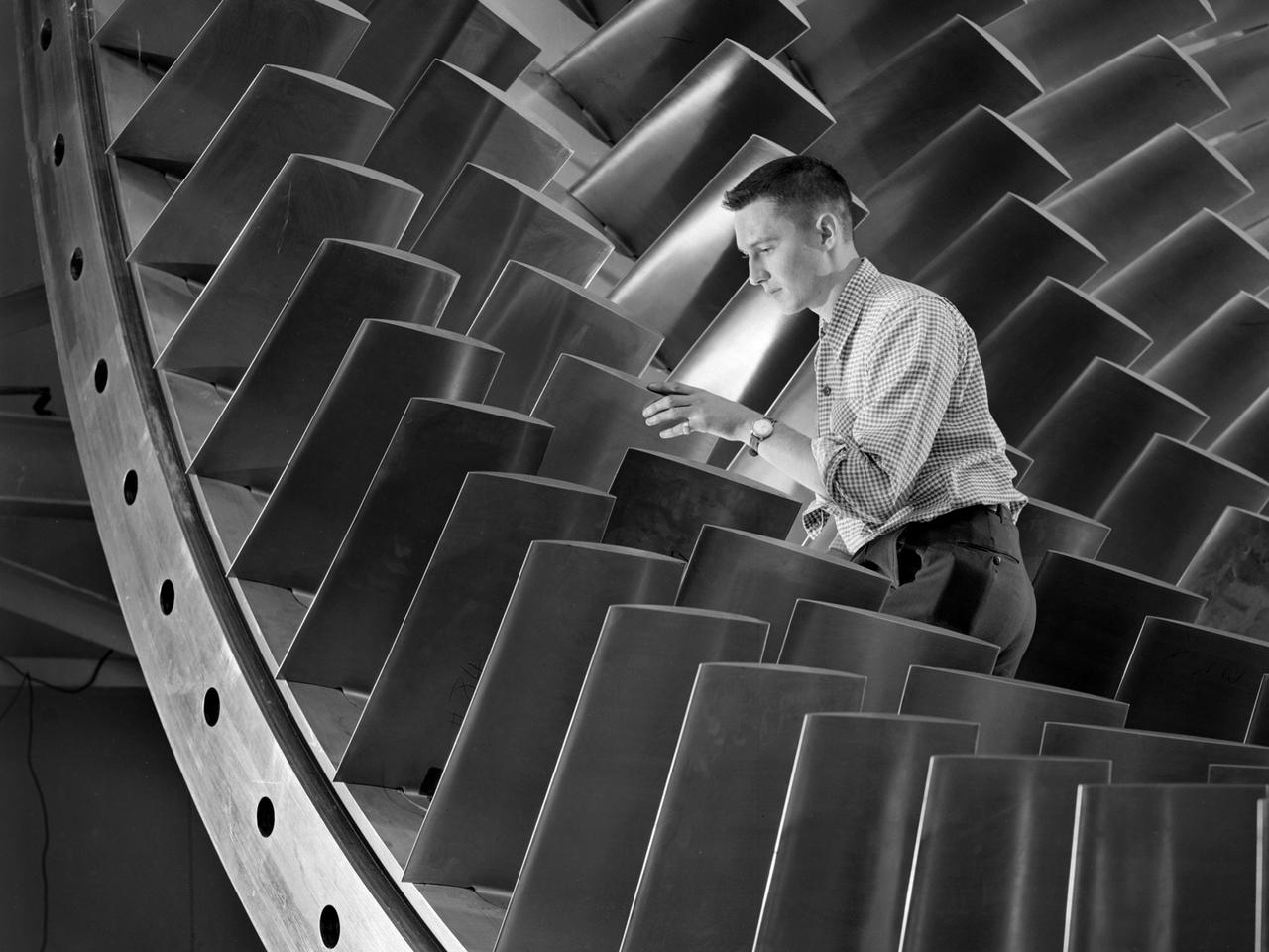
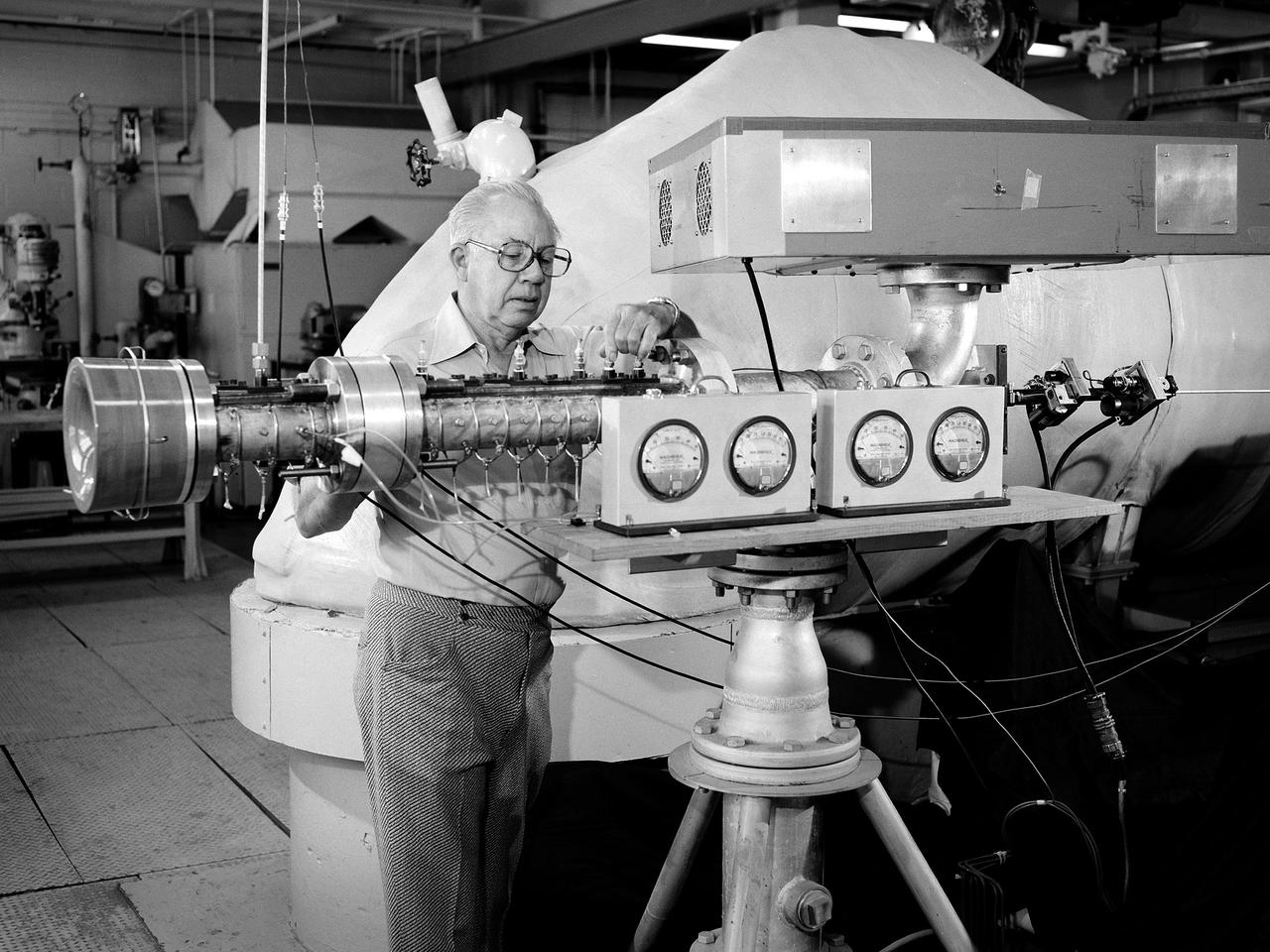
An engineer examines the main compressor for the 10- by 10-Foot Supersonic Wind Tunnel at the National Advisory Committee for Aeronautics (NACA) Lewis Flight Propulsion Laboratory. The engineers were preparing the new wind tunnel for its initial runs in early 1956. The 10- by 10 was the most powerful propulsion wind tunnel in the nation. The facility was part of Congress’ Unitary Plan Act which coordinated wind tunnel construction at the NACA, Air Force, industry, and universities. The 10- by 10 was the largest of the three NACA tunnels built under the act. The 20-foot diameter eight-stage axial flow compressor, seen in this photograph, could generate air flows up to Mach 2.5 through the test section. The stainless steel compressor had 584 blades ranging from 1.8 to 3.25 feet in length. This main compressor was complemented by a secondary axial flow compressor. Working in tandem the two could generate wind streams up to Mach 3.5. The Cleveland Chamber of Commerce presented NACA Lewis photographer Bill Bowles with a second place award for this photograph in their Business and Professional category. The photograph was published in October 1955 edition of its periodical, The Clevelander, which highlighted local professional photographers. Fellow Lewis photographer Gene Giczy won second place in another category for a photograph of Cleveland Municipal Airport.

Significant ice build-up on the Simulated Inter-compressor Duct Research Model (SIDRM) at the Icing Research Tunnel. Photo Credit: (NASA/Jordan Salkin)

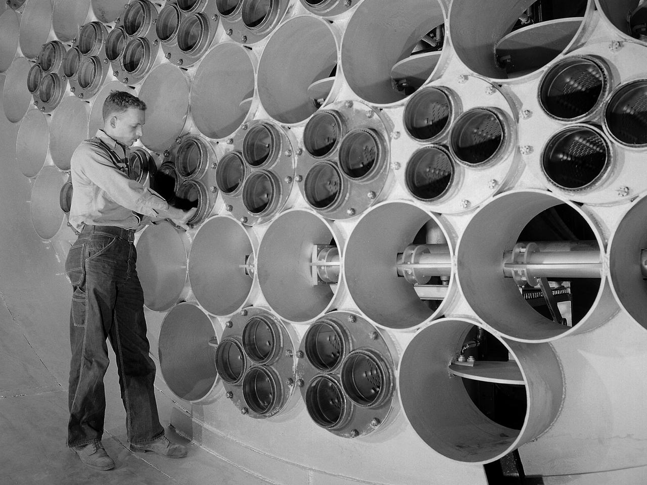
These compressors inside the Refrigeration Building at the National Advisory Committee for Aeronautics (NACA) Aircraft Engine Research Laboratory were used to generate cold temperatures in the Altitude Wind Tunnel (AWT) and Icing Research Tunnel. The AWT was a large facility that simulated actual flight conditions at high altitudes. The two primary aspects of altitude simulation are the reduction of the air pressure and the decrease of temperature. The Icing Research Tunnel was a smaller facility in which water droplets were added to the refrigerated air stream to simulate weather conditions that produced ice buildup on aircraft. The military pressured the NACA to complete the tunnels quickly so they could be of use during World War II. The NACA engineers struggled with the design of this refrigeration system, so Willis Carrier, whose Carrier Corporation had pioneered modern refrigeration, took on the project. The Carrier engineers devised the largest cooling system of its kind in the world. The system could lower the tunnels’ air temperature to –47⁰ F. The cooling system was powered by 14 Carrier and York compressors, seen in this photograph, which were housed in the Refrigeration Building between the two wind tunnels. The compressors converted the Freon 12 refrigerant into a liquid. The refrigerant was then pumped into zig-zag banks of cooling coils inside the tunnels’ return leg. The Freon absorbed heat from the airflow as it passed through the coils. The heat was transferred to the cooling water and sent to the cooling tower where it was dissipated into the atmosphere.
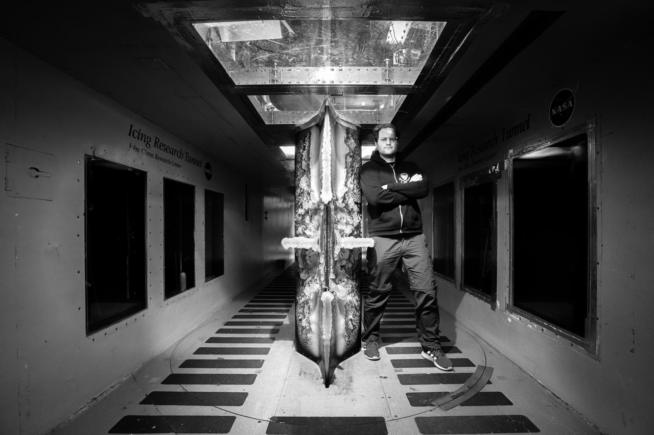
Lead researcher Tadas Bartkus poses after a run of his test with significant ice build-up on the Simulated Inter-compressor Duct Research Model (SIDRM) at the Icing Research Tunnel. Photo Credit: (NASA/Jordan Salkin)

A technician at the National Advisory Committee for Aeronautics (NACA) Lewis Flight Propulsion Laboratory examines one of the massive axial-flow compressor stages that created the high-speed air flow through the 8- by 6-Foot Supersonic Wind Tunnel. The tunnel’s first run was on April 3, 1949, just over a week before this photograph was taken. The 8- by 6 was the laboratory’s first large supersonic wind tunnel and the NACA’s largest supersonic tunnel at the time. The 8- by 6-foot tunnel was originally an open-throat non-return tunnel. The supersonic air flow was blown through the tubular facility and expelled out the other end into the atmosphere with a roar. Complaints from the local community led to the addition of a muffler at the tunnel exit in 1956 and the eventual addition of a return leg. The return leg allowed the tunnel to be operated as either an open system with large doors venting directly to the atmosphere for propulsion system tests or as a closed loop for aerodynamic tests. The air flow was generated by a large seven-stage axial-flow compressor, seen in this photograph, that was powered by three electric motors with a combined 87,000 horsepower. The system required 36,000 kilowatts of power per hour to generate wind velocities of Mach 1.5, and 72,000 kilowatts per hour for Mach 2.0.
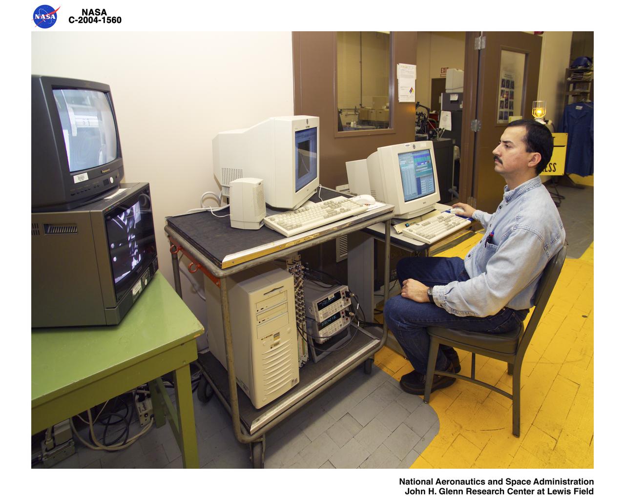
The Central Processing System at Glenn Research Center controls operations in the wind tunnels, propulsion systems lab, engine components research lab, and compressor, turbine and combustor test cells. Documentation photos of the facility were taken on December 19, 2023. Photo Credit: (NASA/Sara Lowthian-Hanna)

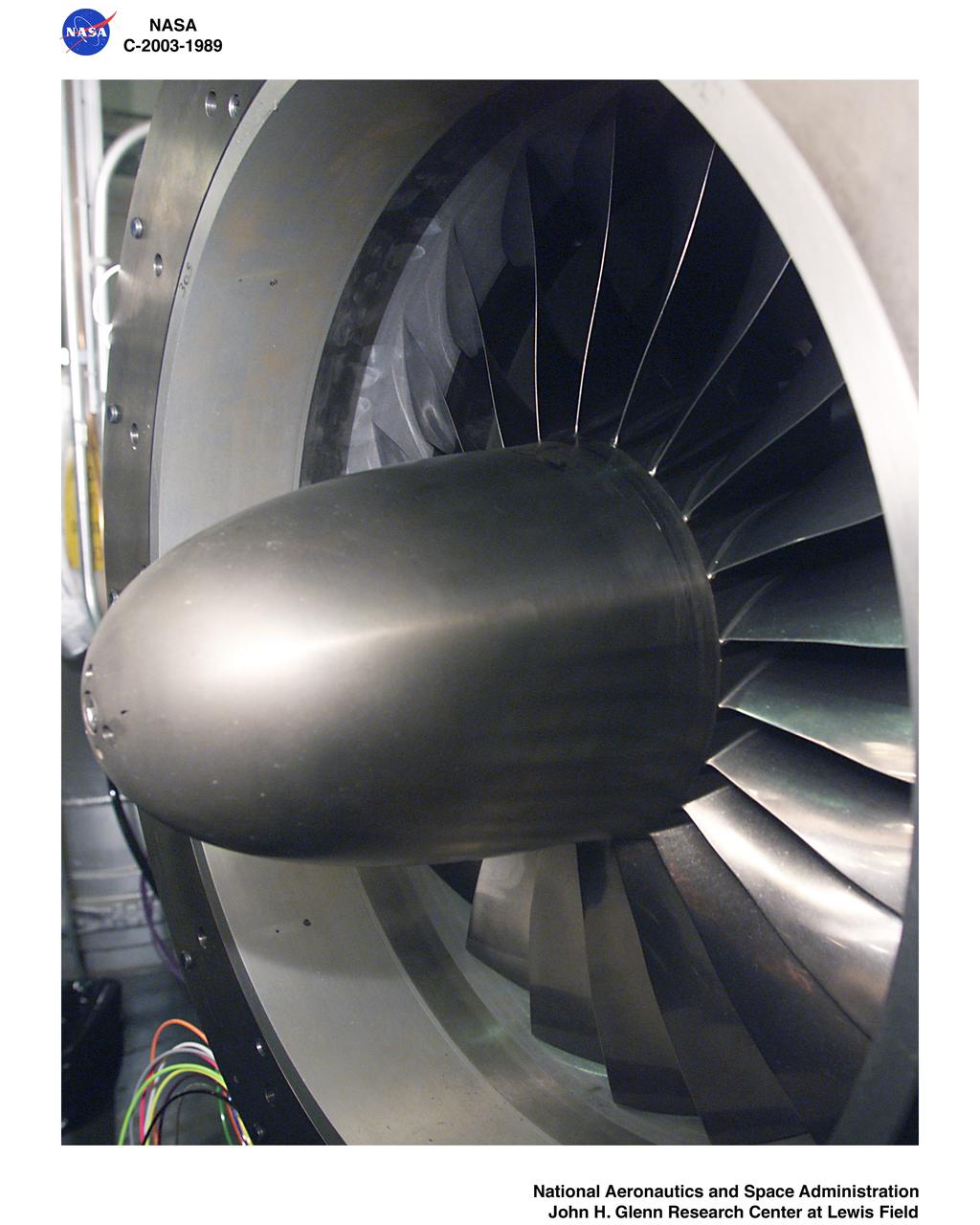
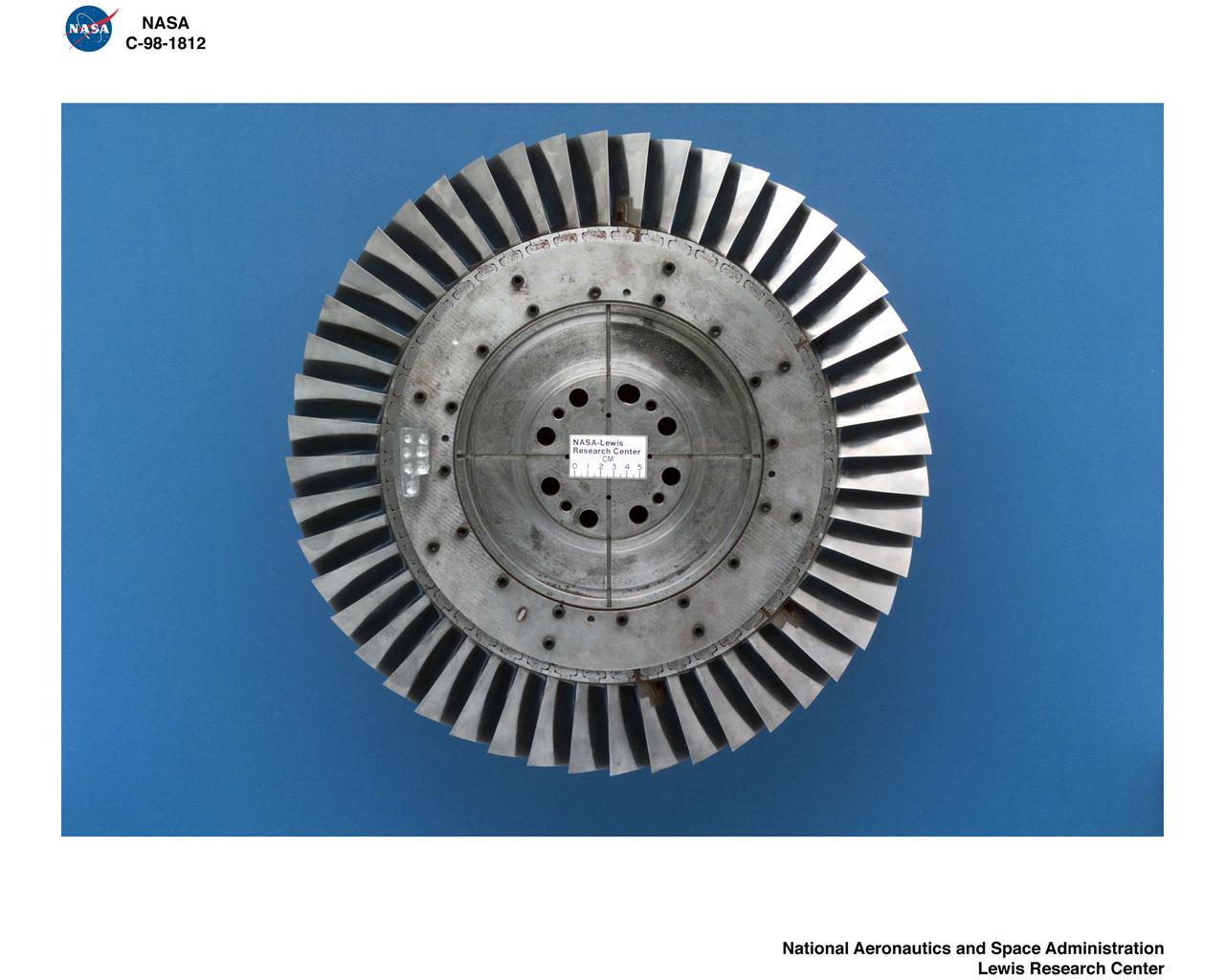
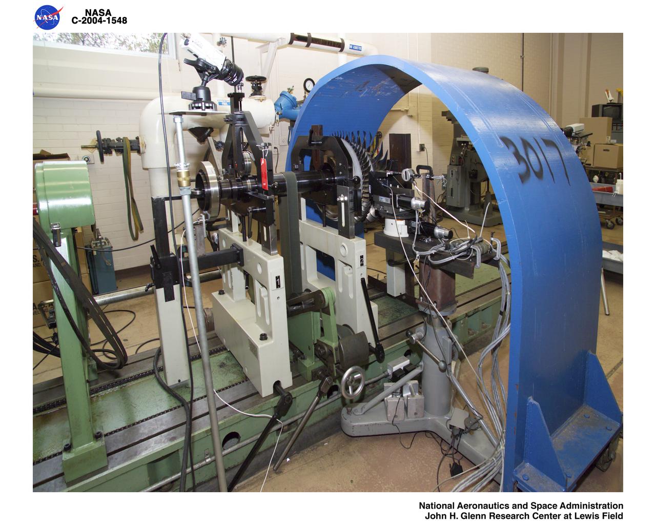
Number 76 Bladeless Compressor for the W-7 Multistage Compressor Facility
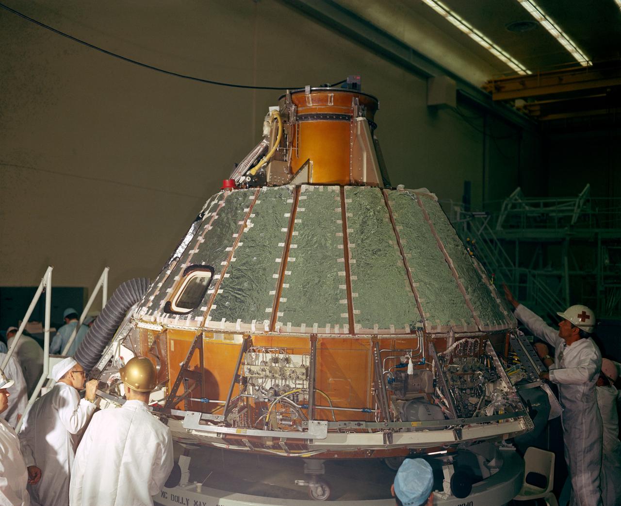
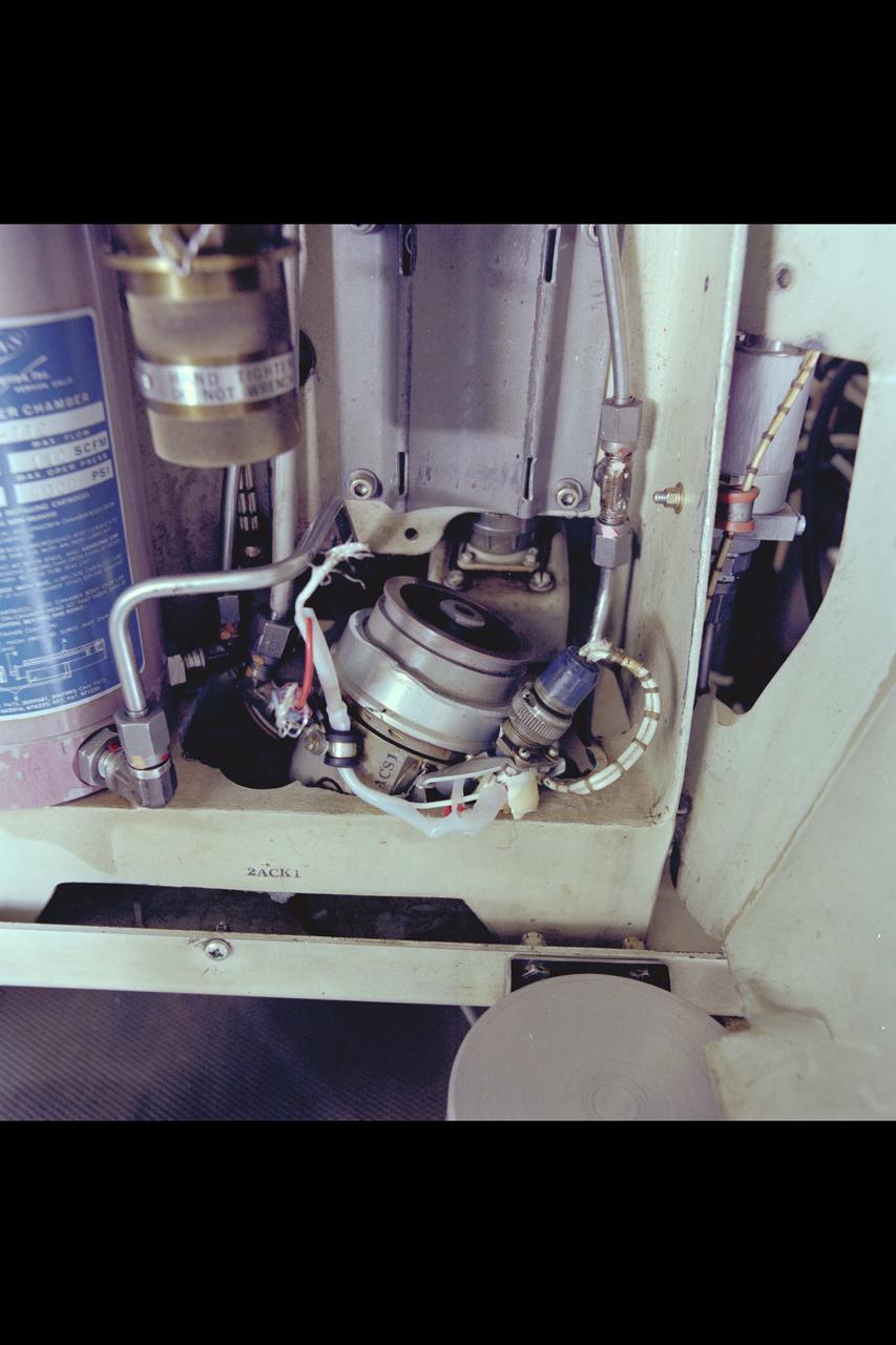
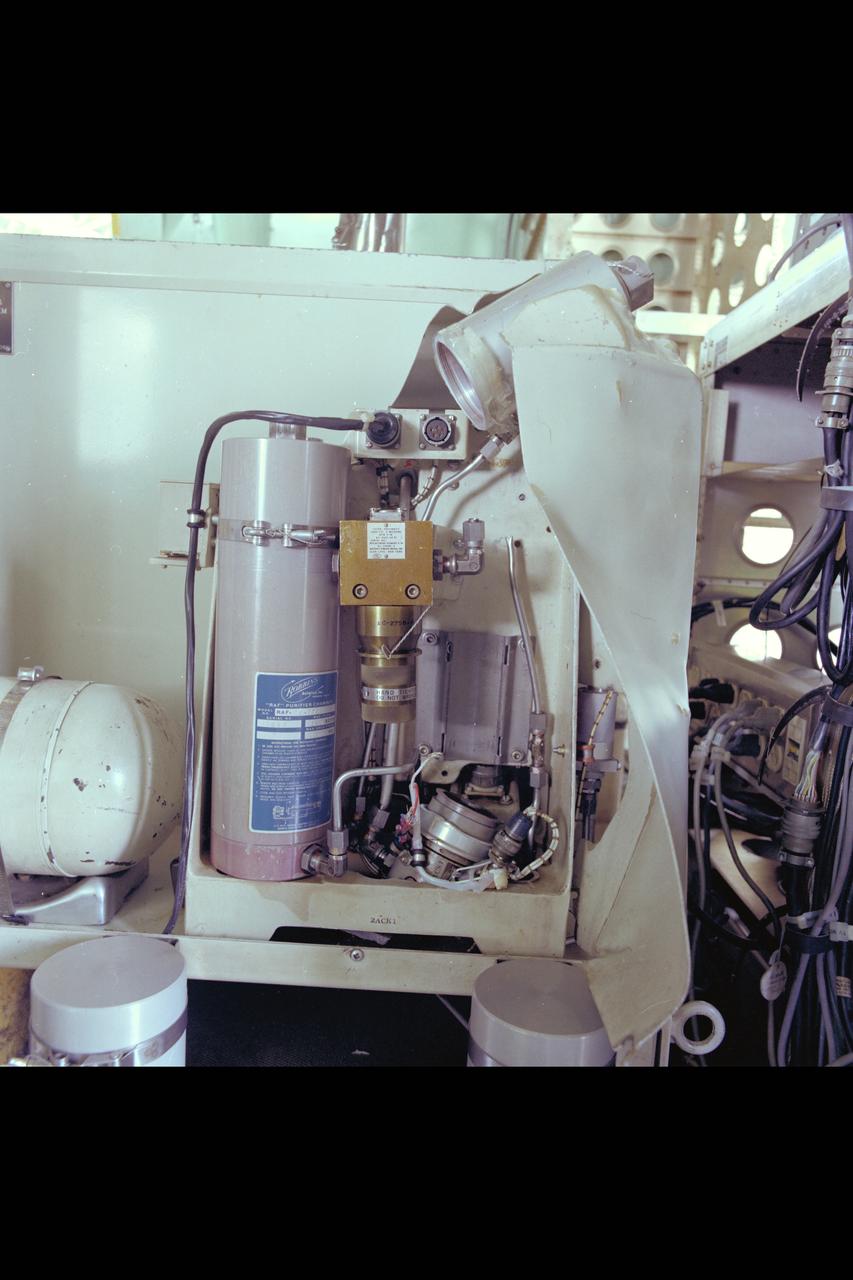
S66-41852 (1966) --- Spacecraft 012 looking toward -Y axis during installation of heat shield. Note uprighting system compressor in aft bay, at right, and Reaction Control System (RCS) valve module panel, center of photo.
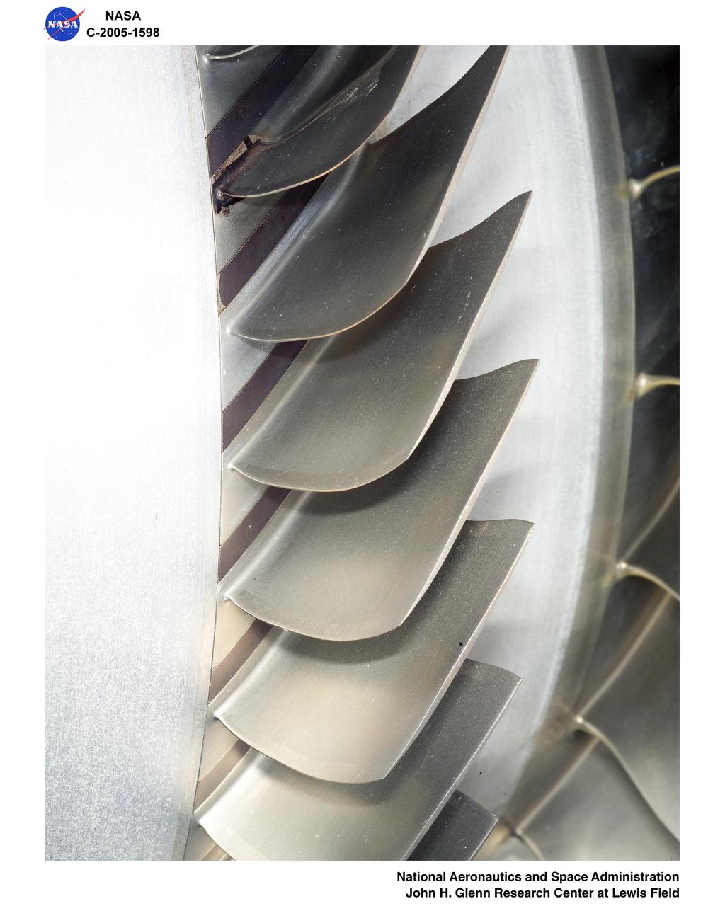
Ultra-Efficient Engine Technology - UEET - Proof of Concept Compressor - POCC - Advanced Compressor Casing Treatment Testing
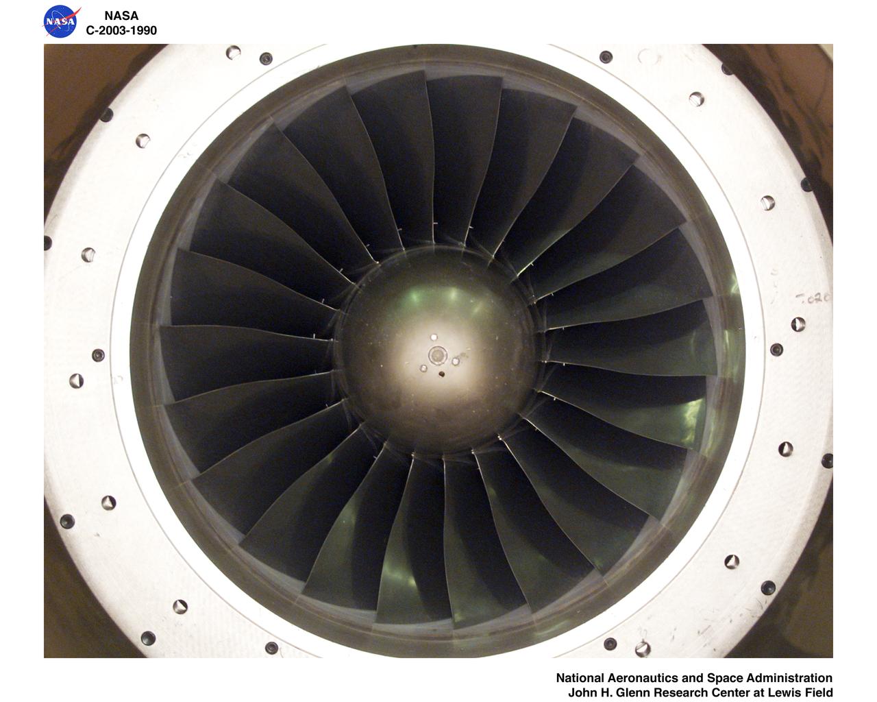
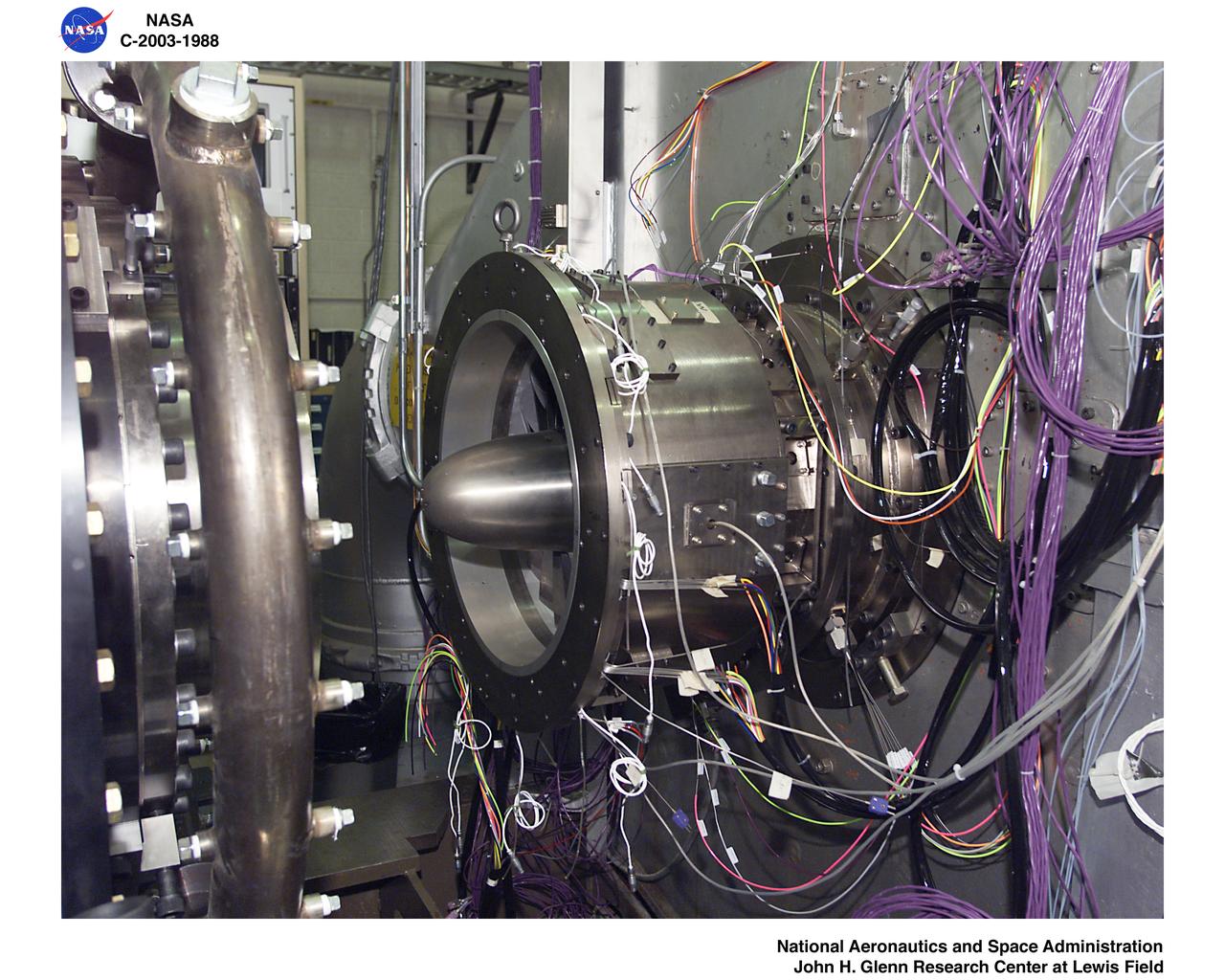
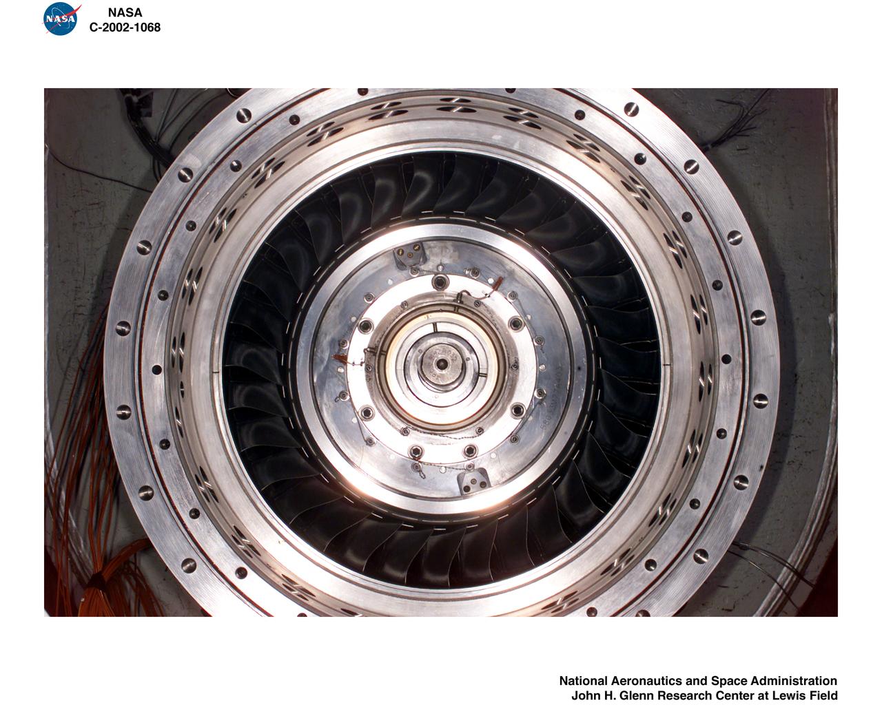
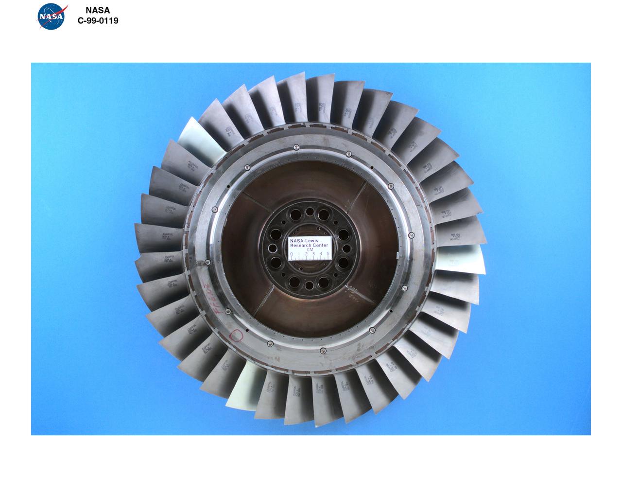
Ultra-Efficient Engine Technology - UEET - Proof of Concept Compressor, Two-stage Compressor
Ultra-Efficient Engine Technology - UEET - Proof of Concept Compressor, Two-stage Compressor
Ultra-Efficient Engine Technology - UEET - Proof of Concept Compressor, Two-stage Compressor
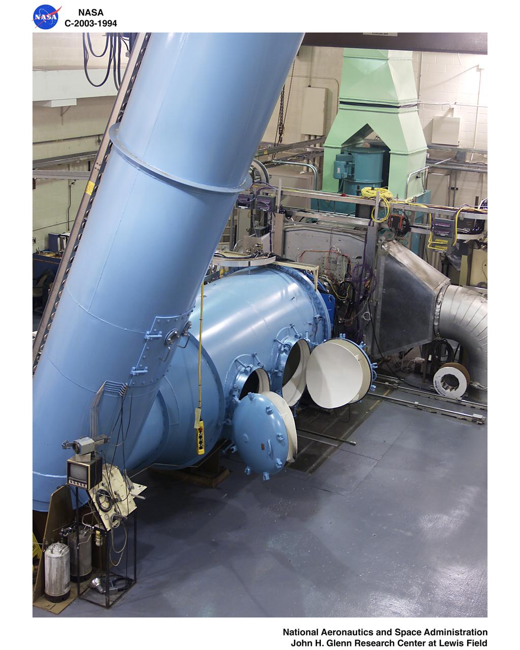
Ultra-Efficient Engine Technology - UEET - Proof of Concept Compressor - POCC - Advanced Compressor Casing Treatment Testing
Ultra-Efficient Engine Technology - UEET - Proof of Concept Compressor - POCC - Advanced Compressor Casing Treatment Testing
Ultra-Efficient Engine Technology - UEET - Proof of Concept Compressor - POCC - Advanced Compressor Casing Treatment Testing
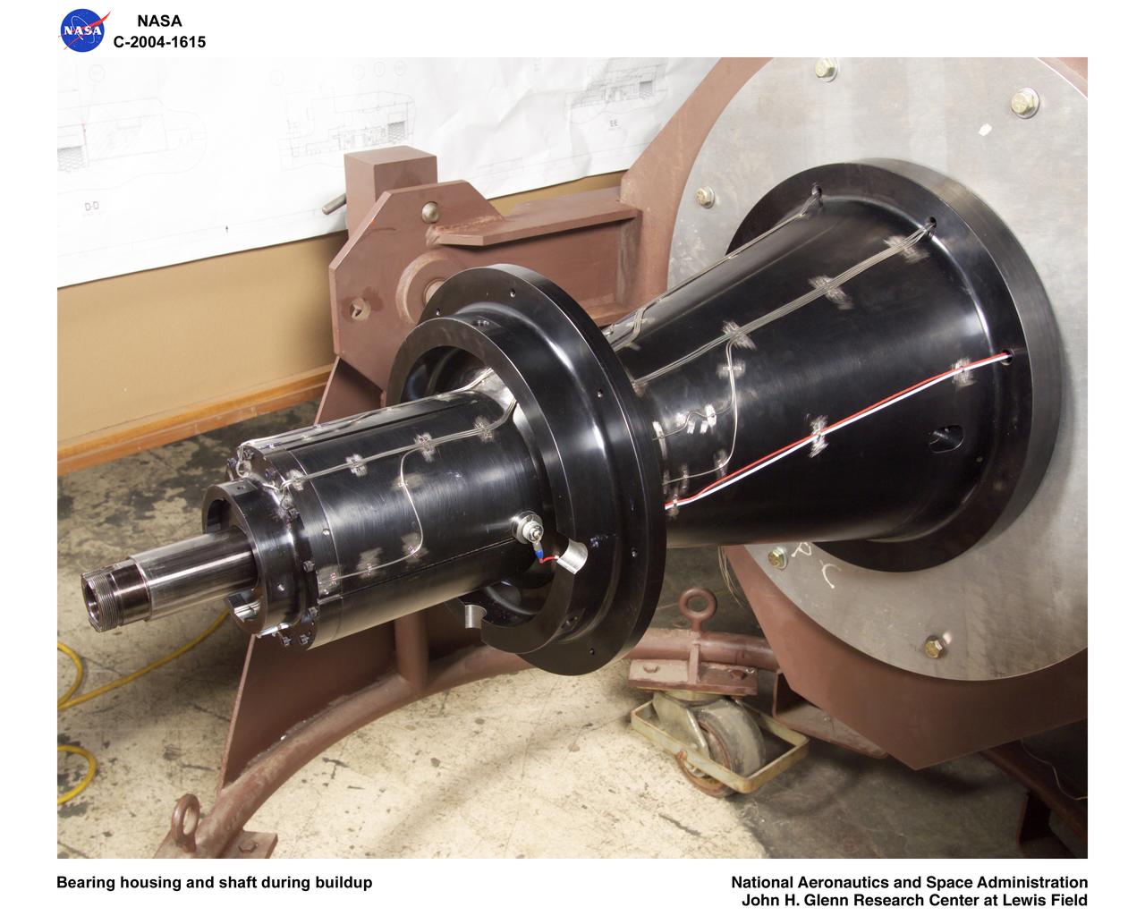
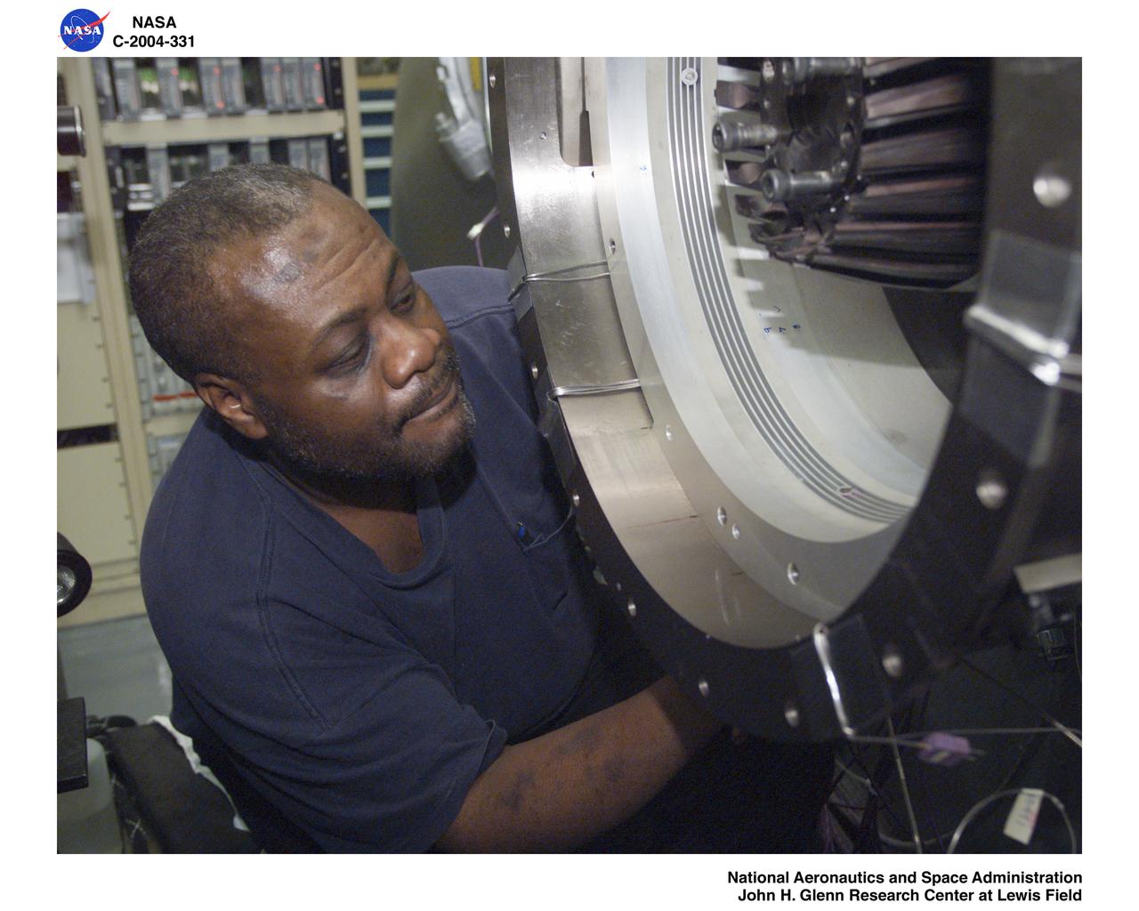
Ultra-Efficient Engine Technology (UEET), Proof of Concept Compressor, Advanced Compressor Casing Treatment testing; bearing housing and shaft during build-up
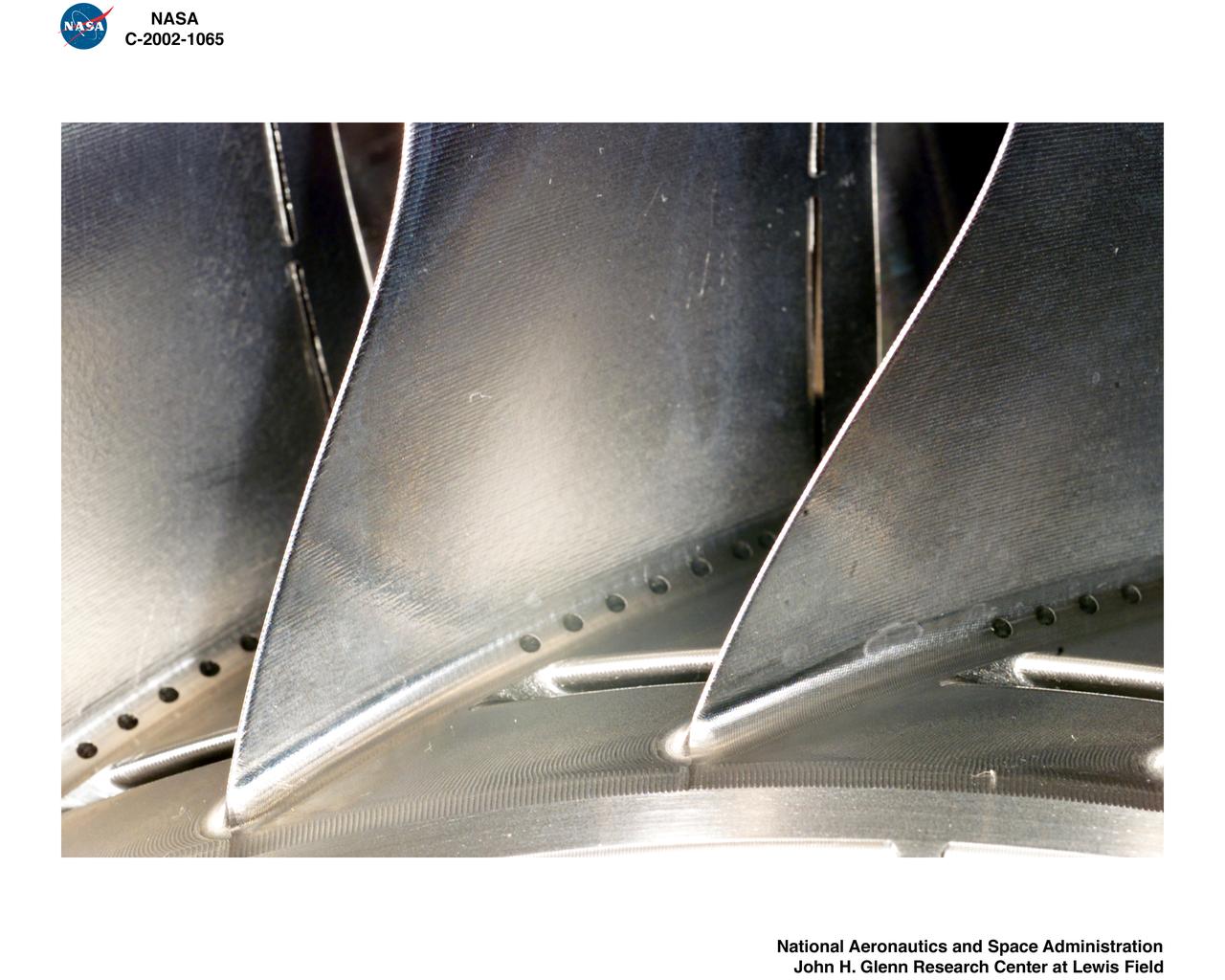
Ultra-Efficient Engine Technology (UEET) Proof of Concept Compressor, Advanced Compressor Casing Treatment testing, First Research Configuration (concentric grooves)
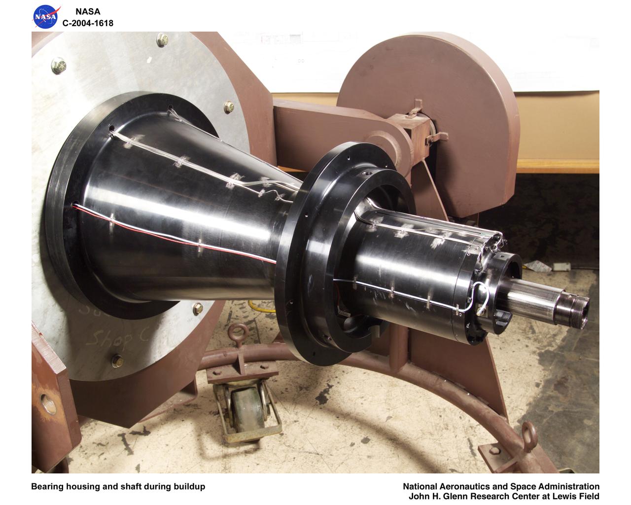
Ultra-Efficient Engine Technology (UEET), Proof of Concept Compressor, Advanced Compressor Casing Treatment testing; bearing housing and shaft during build-up
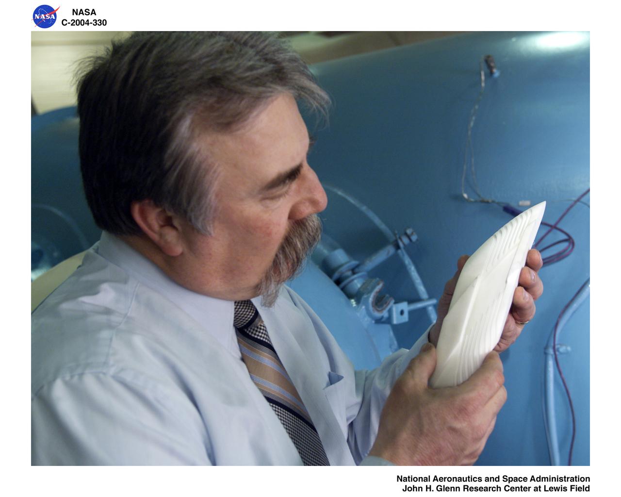
Ultra-Efficient Engine Technology (UEET) Proof of Concept Compressor, Advanced Compressor Casing Treatment testing, First Research Configuration (concentric grooves)
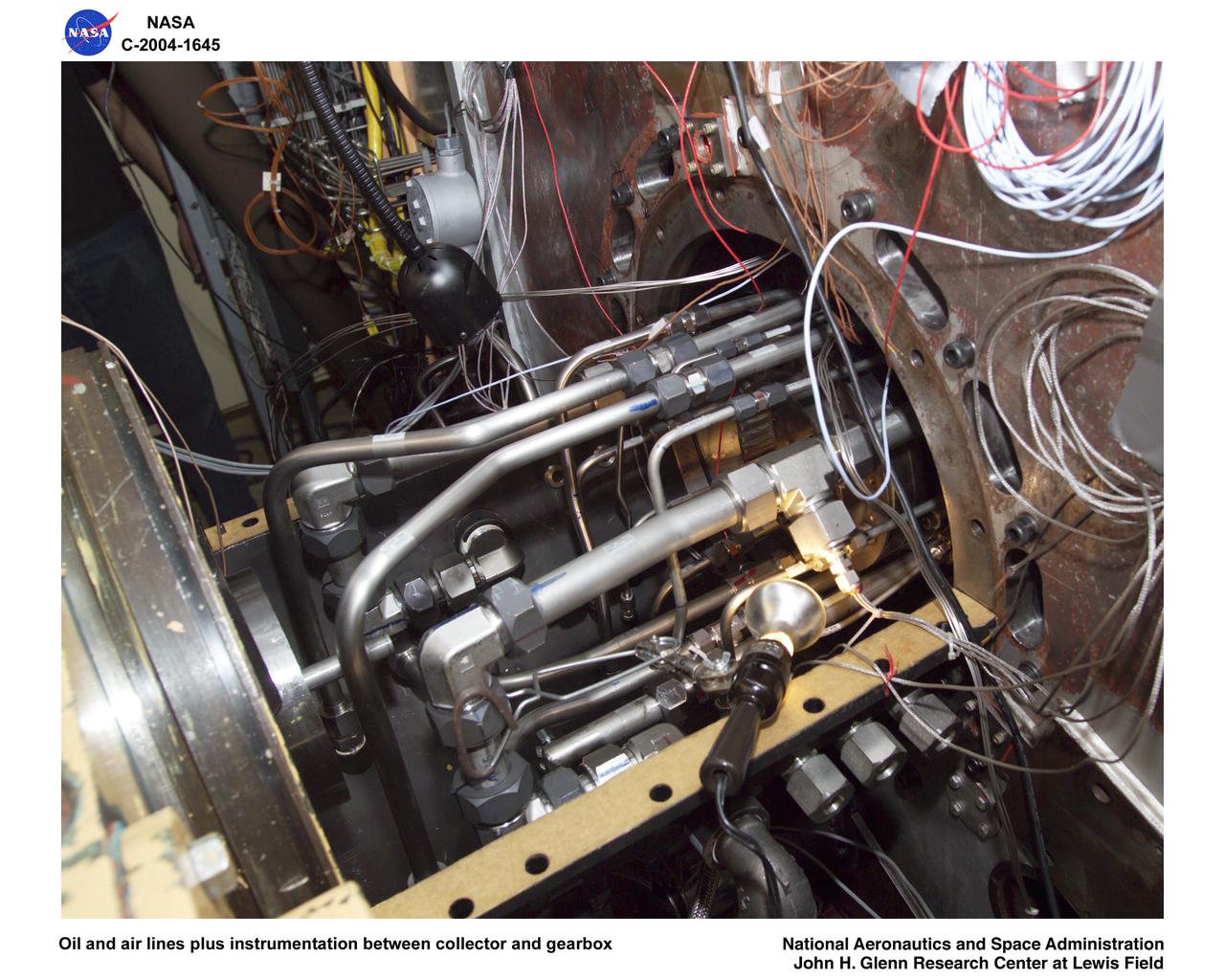
Ultra-Efficient Engine Technology (UEET), Proof of Concept Compressor, Advanced Compressor Casing Treatment testing; oil and air lines plus instrumentation between collector and gearbox
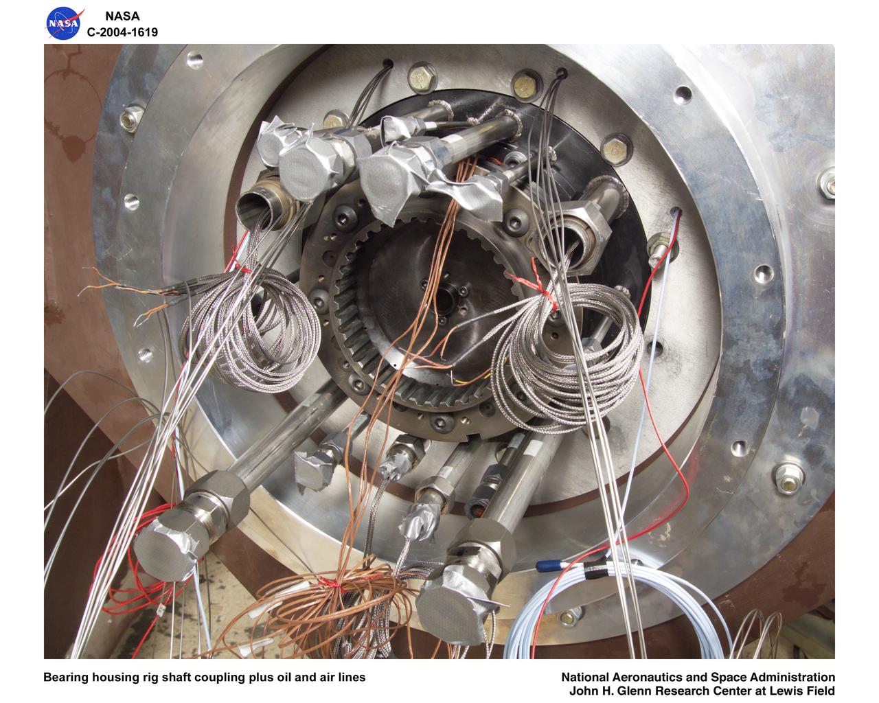
Ultra-Efficient Engine Technology (UEET), Proof of Concept Compressor, Advanced Compressor Casing Treatment testing; bearing housing rig shaft coupling and oil, air lines

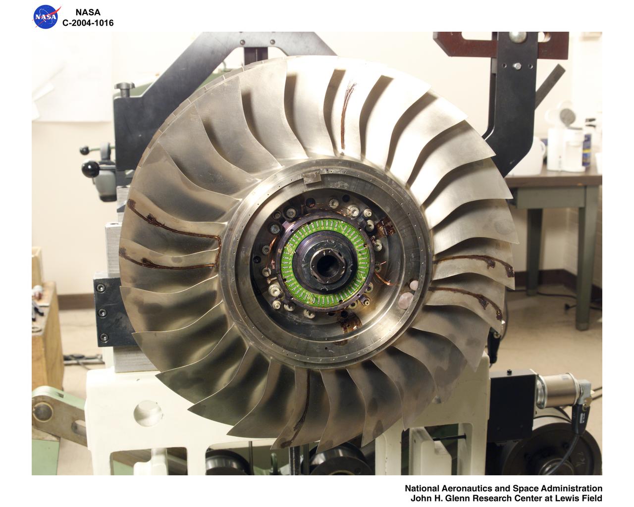
COMPRESSOR IMPELLER DAMAGE
ASPIRATED COMPRESSOR STATOR AND CASING
ASPIRATED COMPRESSOR STATOR AND CASING

ASPIRATED COMPRESSOR AND RINGS
ASPIRATED COMPRESSOR STATOR AND CASING
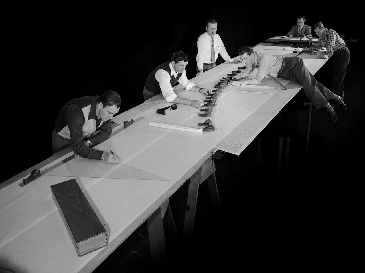
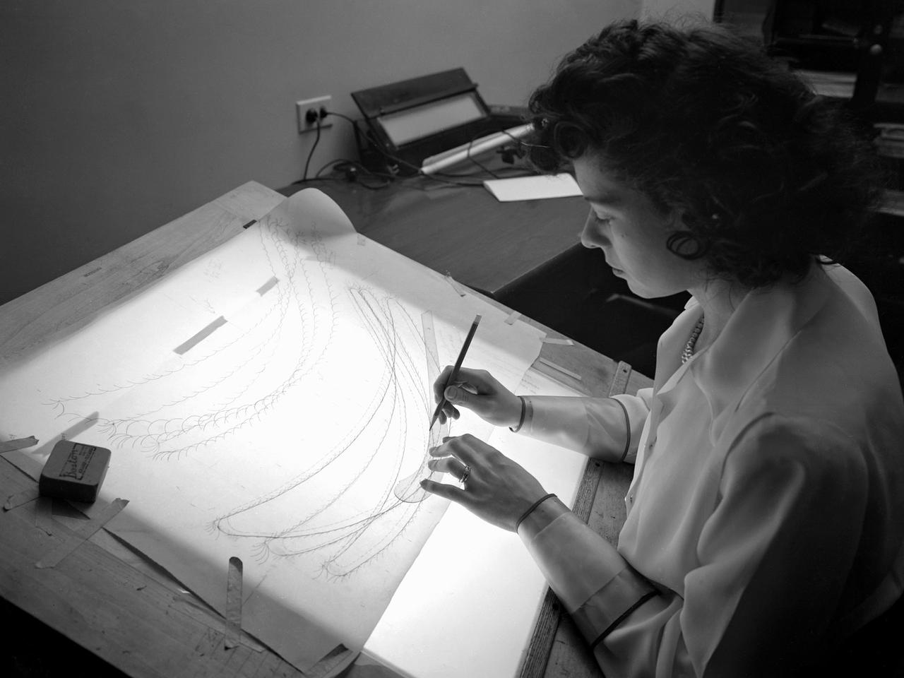
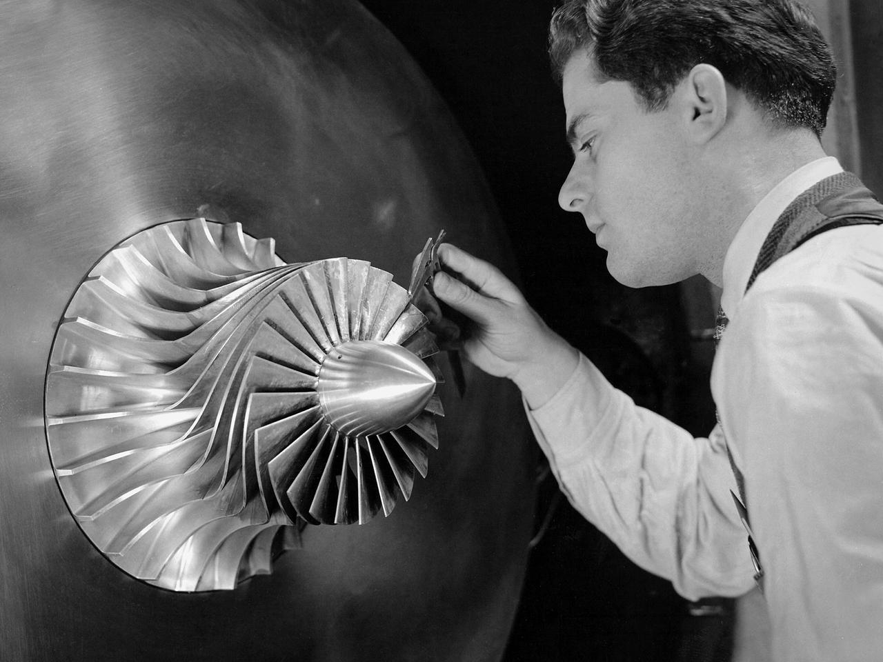
Draftsmen in the Materials and Stresses Building at the National Advisory Committee for Aeronautics (NACA) Lewis Flight Propulsion Laboratory create a template for a compressor using actual compressor blades. The Compressor and Turbine Division contained four sections of researchers dedicated to creating better engine components. The Materials and Thermodynamics Division studied the strength, durability, heat transfer characteristics, and physical composition of various materials. The two divisions were important to the research and development of new aircraft engines. The constant battle to increase the engine’s thrust while decreasing its overall weight resulted in additional stress on jet engine components, particularly compressors. As speed and maneuverability were enhanced, the strain on the engines and inlets grew. For decades NACA Lewis researchers continually sought to improve compressor blade design, develop stronger composite materials, and minimize flutter and inlet distortions.
C-141 KAO: CAT experiment - Damage Compressor

Single Spool Compressor & Turbine Camera file: 45548252
C-141 KAO: CAT experiment - compressor damage
C-141 KAO: CAT experiment - Damage Compressor
The CPS controls operations used by Glenn Research Center's wind tunnels, propulsion systems lab, engine components research lab, and compressor, turbine and combustor test cells. Used widely throughout the lab, it operates equipment such as exhausters, chillers, cooling towers, compressors, dehydrators, and other such equipment.
ROTOR 38 FOR SINGLE STAGE COMPRESSOR FACILITY W-8
Ultra-Efficient Engine Technology Proof of Concept Compressor, Gearbox
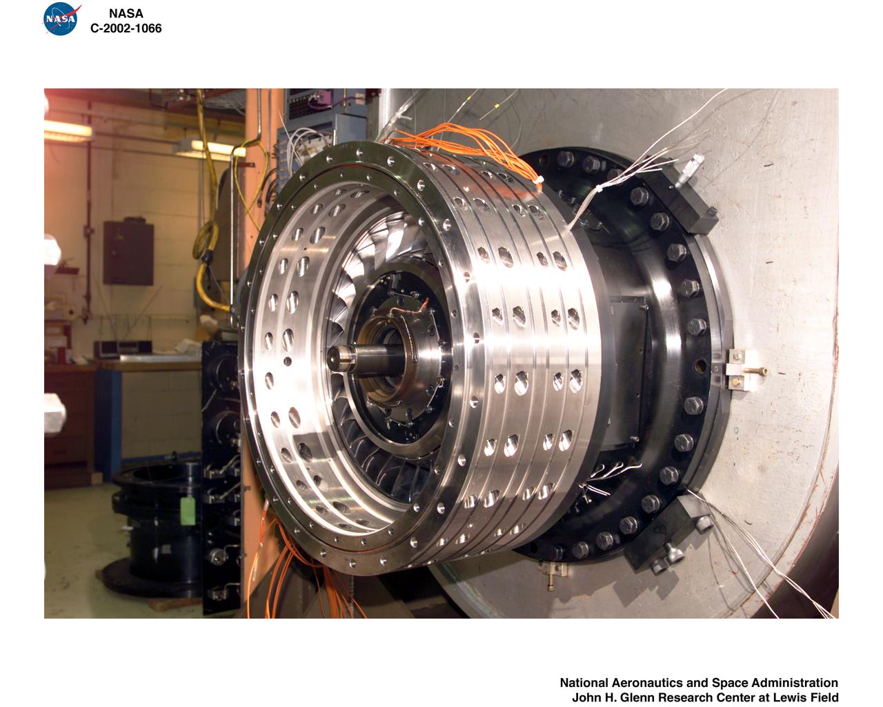
Ultra-Efficient Engine Technology (UEET) Proof of Concept Compressor (POCC)
DAMAGED ROTOR 37 BLADES SINGLE STAGE COMPRESSOR FACILITY
Ultra-Efficient Engine Technology (UEET) Proof of Concept Compressor (POCC)
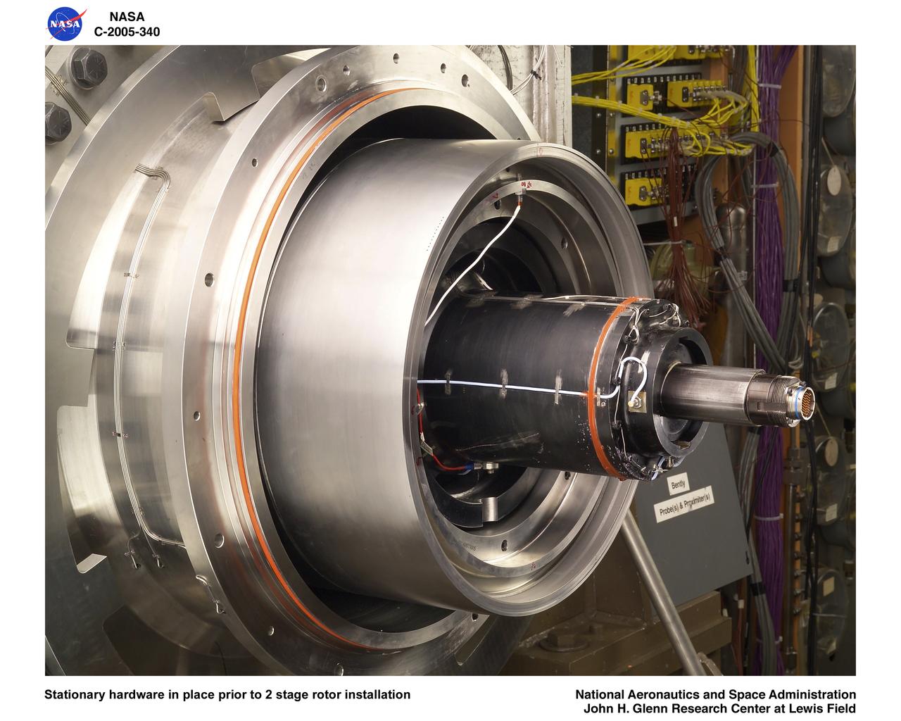
Ultra-Efficient Engine Technology (UEET) Proof of Concept Compressor, Stationary hardware in place prior to 2 stage rotor installation
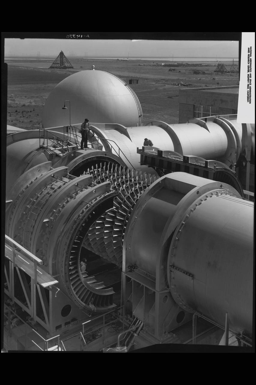
NACA Ames Research Center's 6x6ft Supersonic Wind Tunnel compressor, showing rotor blades
Ultra-Efficient Engine Technology (UEET), Proof of Concept Compressor, Shaft / Rotor Balance Assembly
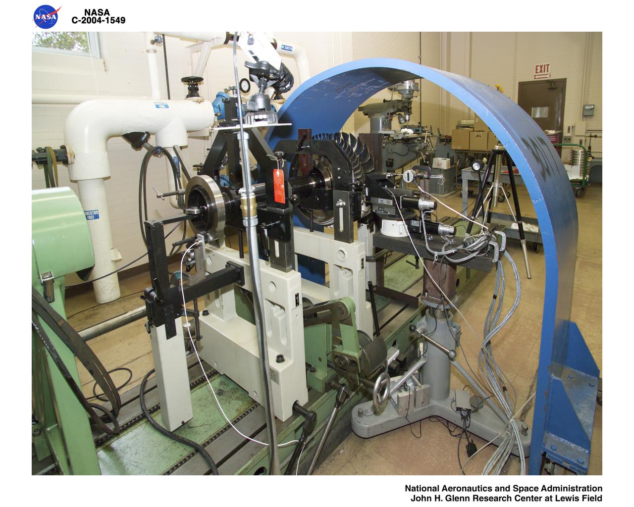
Ultra Efficient Engine Technology (UEET) W-7 2-Stage Proof of Concept Compressor - Blade Tip Clearance Sensor Calibration
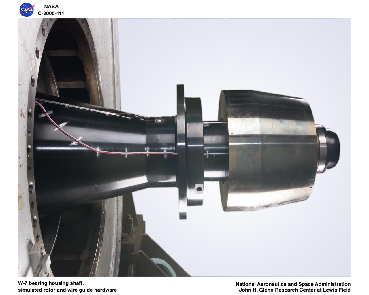
Ultra-Efficient Engine Technology (UEET), Proof of Concept Compressor, W-7 bearing housing shaft, simulated rotor wire guide hardware
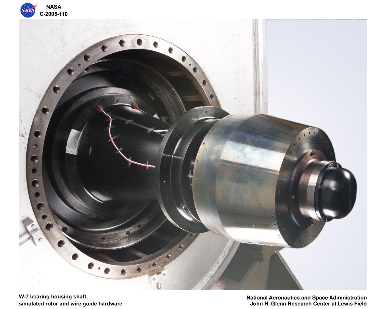
Ultra-Efficient Engine Technology (UEET), Proof of Concept Compressor, W-7 bearing housing shaft, simulated rotor wire guide hardware
Ultra Efficient Engine Technology (UEET) W-7 2-Stage Proof of Concept Compressor - Blade Tip Clearance Sensor Calibration
Ultra Efficient Engine Technology (UEET) W-7 2-Stage Proof of Concept Compressor - Blade Tip Clearance Sensor Calibration
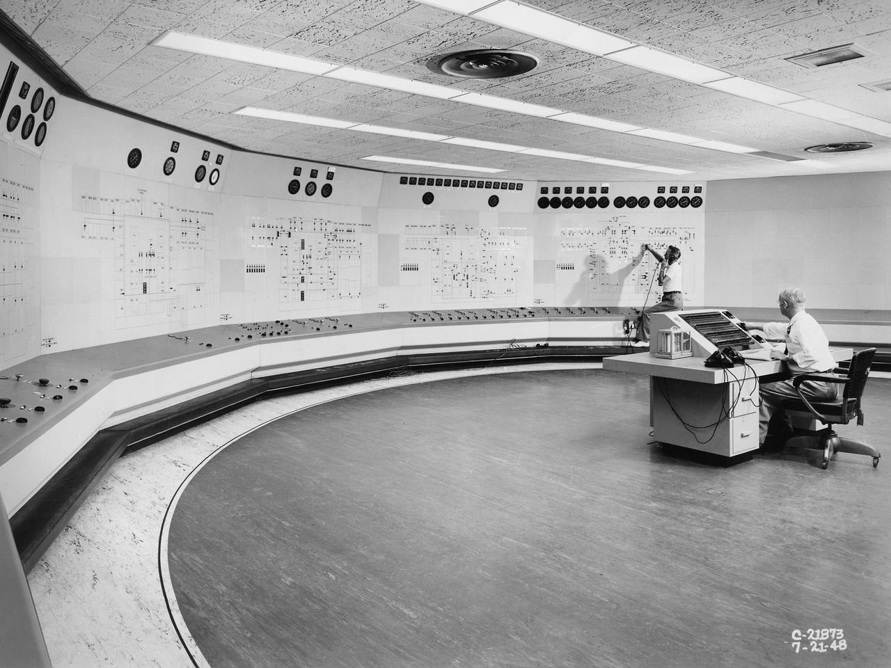
Operators in the Engine Research Building’s Central Control Room at the National Advisory Committee for Aeronautics (NACA) Lewis Flight Propulsion Laboratory. The massive 4.25-acre Engine Research Building contains dozens of test cells, test stands, and altitude chambers. A powerful collection of compressors and exhausters located in the central portion of the basement provided process air and exhaust for these test areas. This system is connected to similar process air systems in the laboratory’s other large test facilities. The Central Control Room coordinates this activity and communicates with the local utilities. This photograph was taken just after a major upgrade to the control room in 1948. The panels on the wall contain rudimentary floor plans of the different Engine Research Building sections with indicator lights and instrumentation for each test cell. The process air equipment included 12 exhausters, four compressors, a refrigeration system, cooling water, and an exhaust system. The operators in the control room kept in contact with engineers running the process air system and those conducting the tests in the test cells. The operators also coordinated with the local power companies to make sure enough electricity was available to operate the powerful compressors and exhausters.
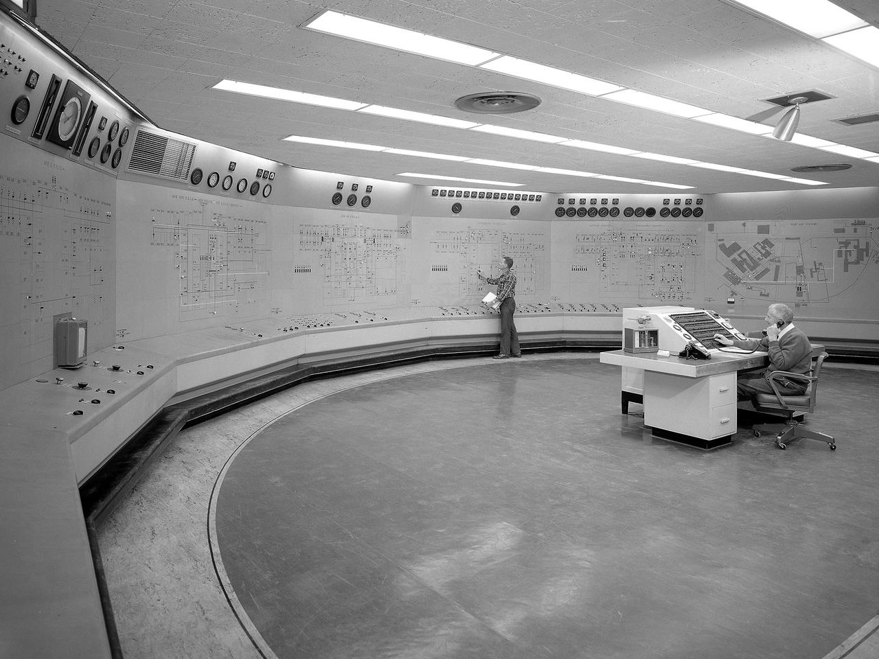
Operators in the Engine Research Building’s Central Control Room at the National Aeronautics and Space Administration (NASA) Lewis Research Center. The massive 4.25-acre Engine Research Building contains dozens of test cells, test stands, and altitude chambers. A powerful a collection of compressors and exhausters located in the central portion of the basement provides process air and exhaust for these test areas. This system is connected to similar process air systems in the laboratory’s other large test facilities. The Central Control Room coordinates this activity and communicates with the local utilities. The panels on the wall contain schematics with indicator lights and instrumentation for the atmospheric exhaust, altitude exhaust, refrigerated air, and process air systems. The process air equipment included twelve exhausters, four compressors, refrigeration system, cooling water, and an exhaust system. The operators in the control room kept in contact with engineers running the process air system and those conducting the tests in the test cells. The operators also coordinated with the local power companies to make sure enough electricity was available to operate the powerful compressors and exhausters.
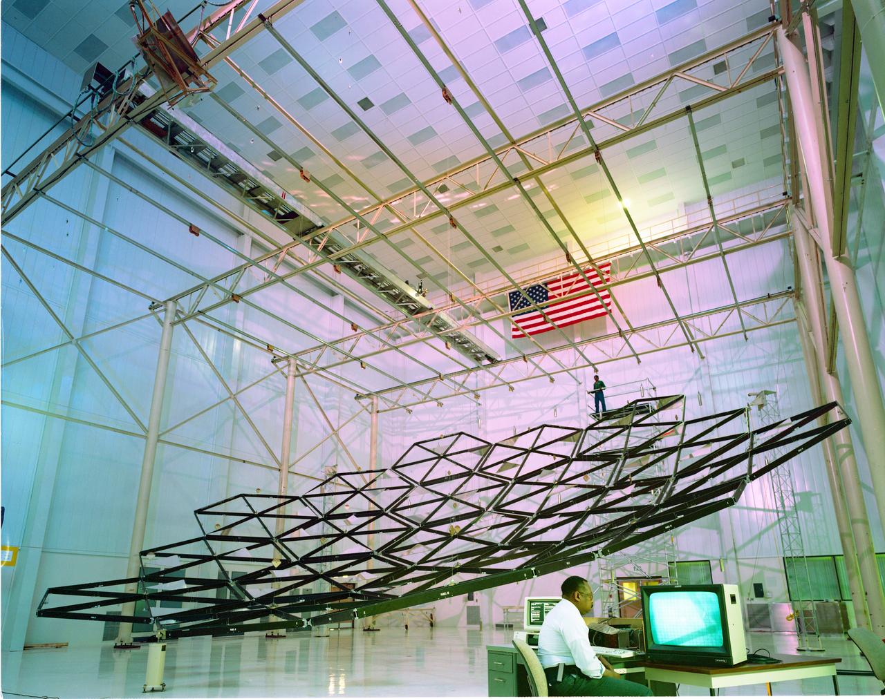
Testing of the Solar Dynamic Collector for Space Freedom. The solar dynamic power system includes a solar concentrator, which collects sunlight; a receiver, which accepts and stores the concentrated solar energy and transfers this energy to a gas; a Brayton turbine, alternator, and compressor unit, which generates electric power; and a radiator, which rejects waste heat.
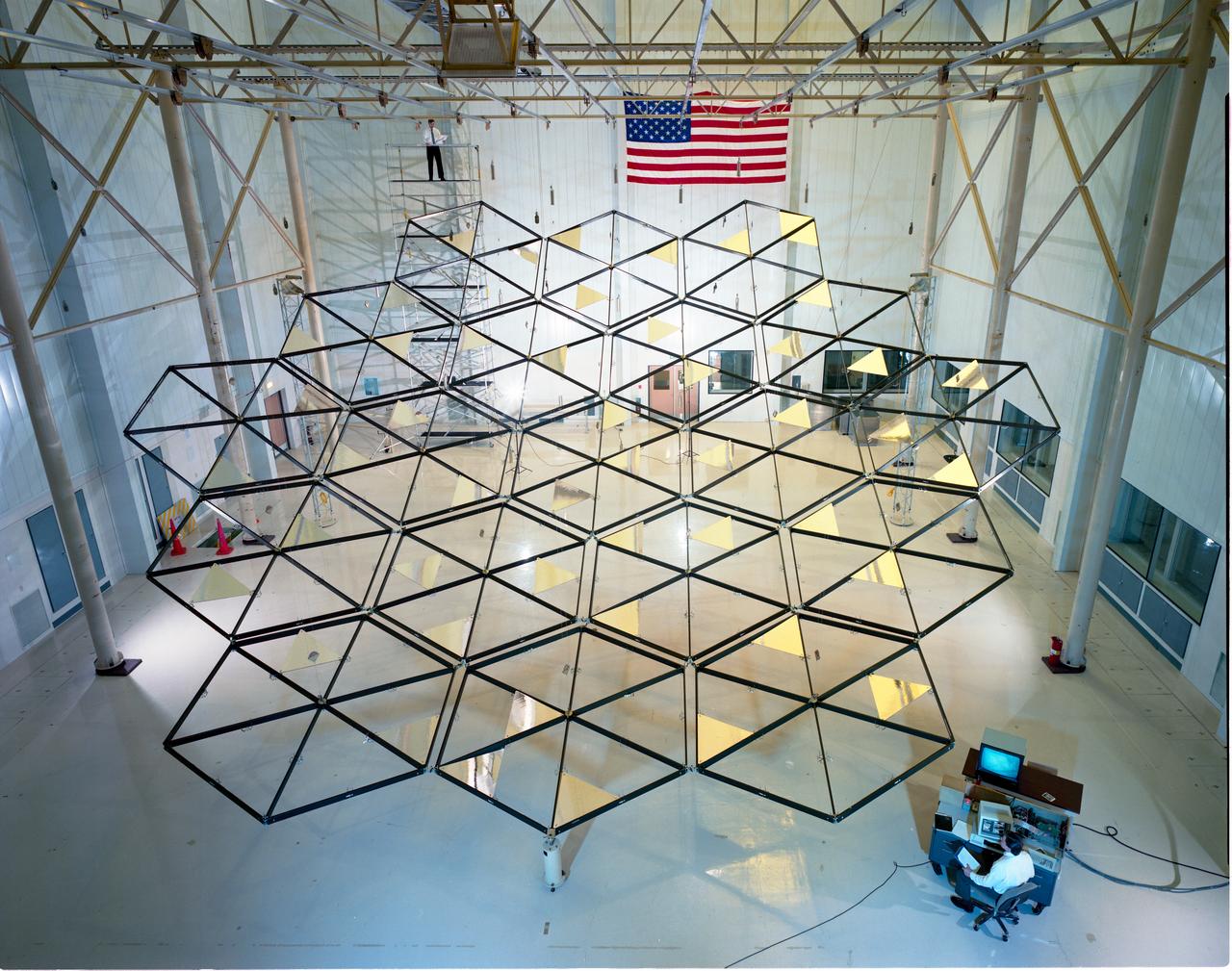
Testing of the Solar Dynamic Collector for Space Freedom. The solar dynamic power system includes a solar concentrator, which collects sunlight; a receiver, which accepts and stores the concentrated solar energy and transfers this energy to a gas; a Brayton turbine, alternator, and compressor unit, which generates electric power; and a radiator, which rejects waste heat.
Acoustic Casing Treatment Testing Completed in the W-8 Single Stage Axial Compressor Facility at NASA Glenn. Four different over-the-rotor acoustic casing treatment concepts were tested along with two baseline configurations. Testing included steady-aerodynamic measurements of fan performance, hotfilm turbulence measurements, and inlet acoustic measurements with an in-duct array.
Acoustic Casing Treatment Testing Completed in the W-8 Single Stage Axial Compressor Facility at NASA Glenn. Four different over-the-rotor acoustic casing treatment concepts were tested along with two baseline configurations. Testing included steady-aerodynamic measurements of fan performance, hotfilm turbulence measurements, and inlet acoustic measurements with an in-duct array.
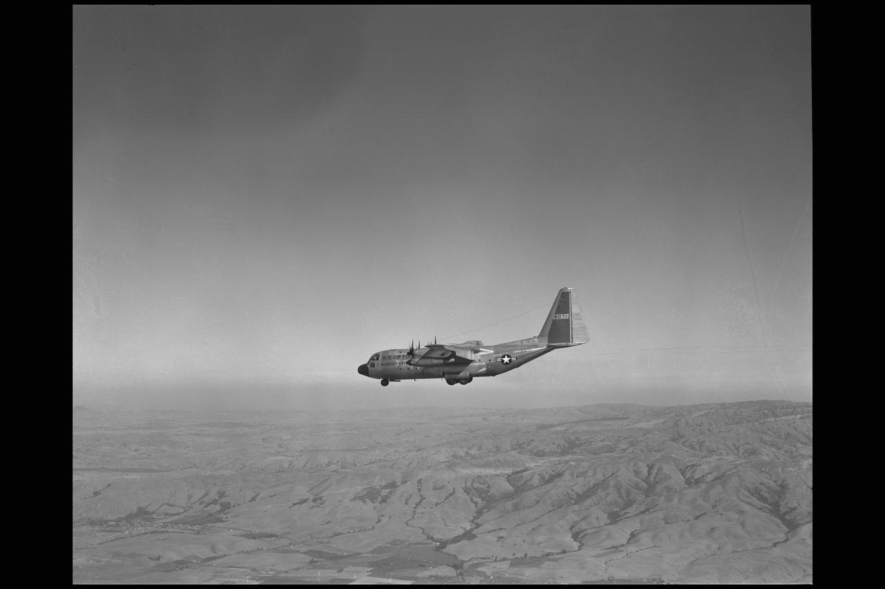
Lockheed NC-130B STOL turboprop-powered aircraft with ailerons drooped 30 degrees. Note trailing-edge flaps deflected 90 degrees for increased lift. Two T-56 turboshaft engines, which drove wing-mounted load compressors for boundary-layer control, are mounted on outboard wing pods. Landing approach speed was reduced 30 knots with boundary-layer control
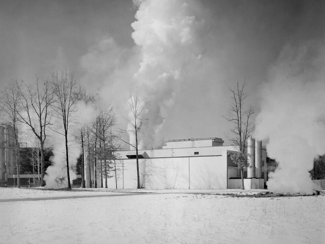
The Engine Propeller Research Building, referred to as the Prop House, emits steam from its acoustic silencers at the National Advisory Committee for Aeronautics (NACA) Lewis Flight Propulsion Laboratory. In 1942 the Prop House became the first completed test facility at the new NACA laboratory in Cleveland, Ohio. It contained four test cells designed to study large reciprocating engines. After World War II, the facility was modified to study turbojet engines. Two of the test cells were divided into smaller test chambers, resulting in a total of six engine stands. During this period the NACA Lewis Materials and Thermodynamics Division used four of the test cells to investigate jet engines constructed with alloys and other high temperature materials. The researchers operated the engines at higher temperatures to study stress, fatigue, rupture, and thermal shock. The Compressor and Turbine Division utilized another test cell to study a NACA-designed compressor installed on a full-scale engine. This design sought to increase engine thrust by increasing its airflow capacity. The higher stage pressure ratio resulted in a reduction of the number of required compressor stages. The last test cell was used at the time by the Engine Research Division to study the effect of high inlet densities on a jet engine. Within a couple years of this photograph the Prop House was significantly altered again. By 1960 the facility was renamed the Electric Propulsion Research Building to better describe its new role in electric propulsion.
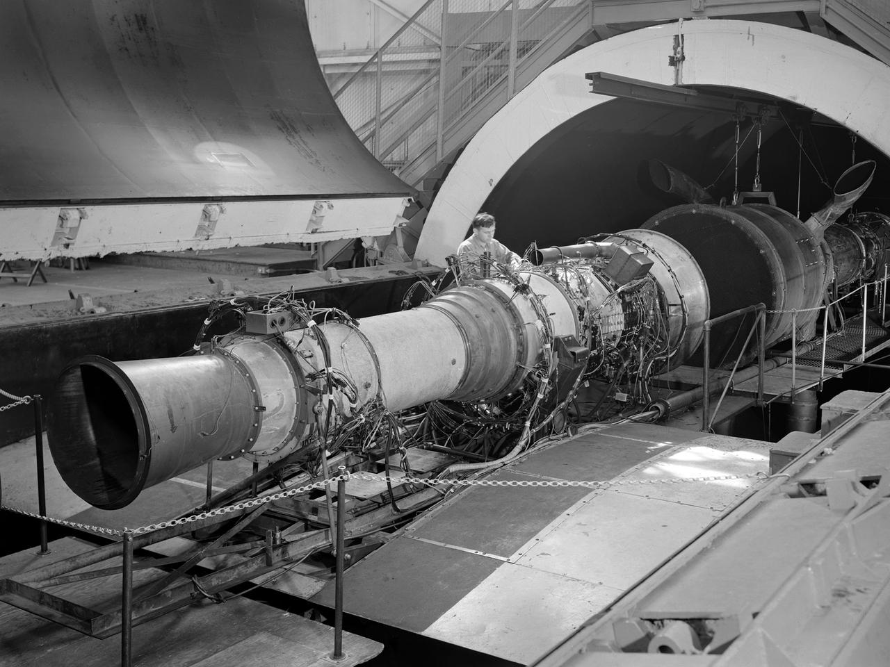
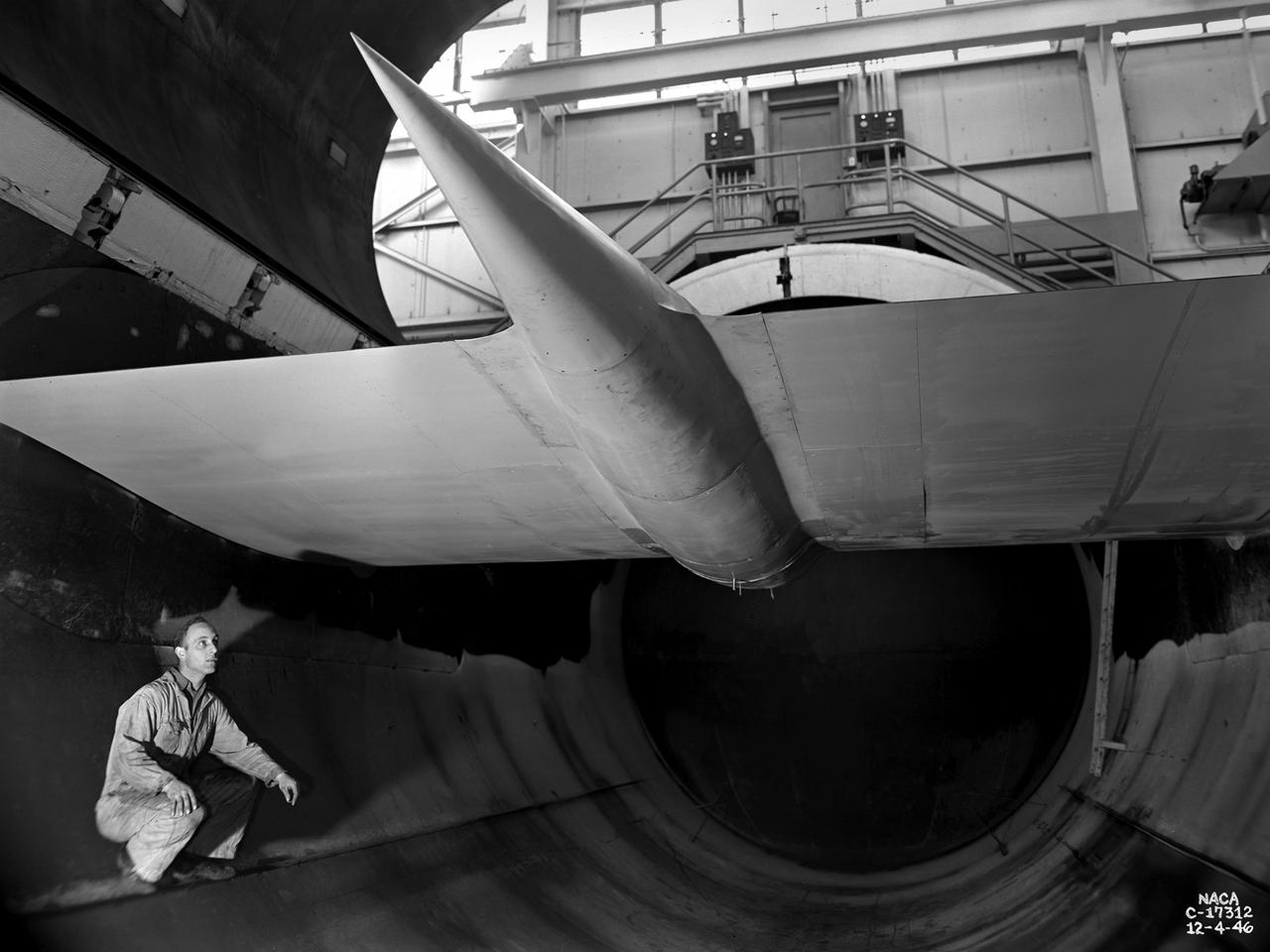
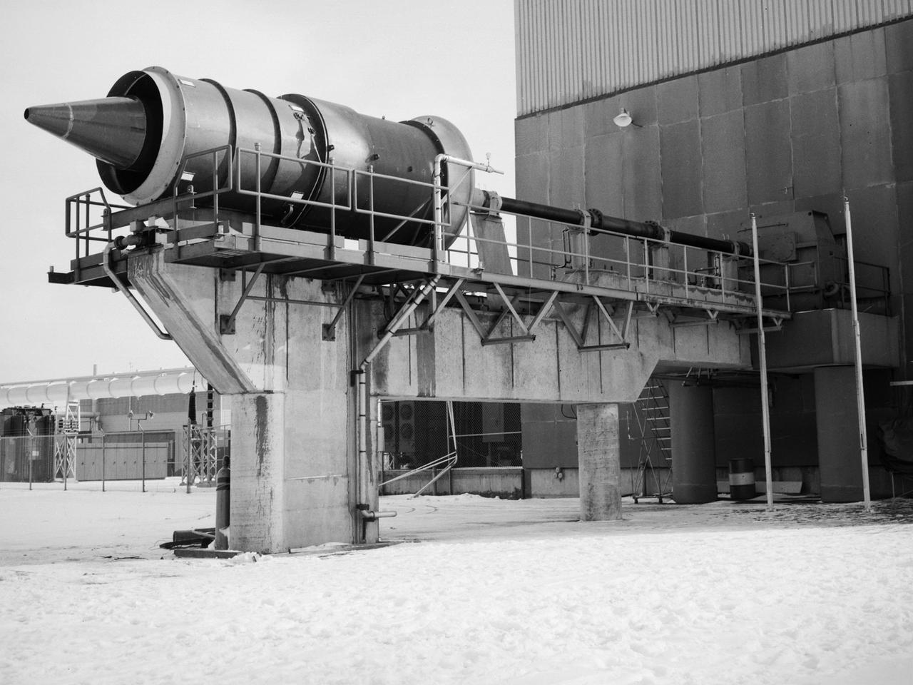
A Rolls Royce Avon RA-14 engine was tested in the Altitude Wind Tunnel at the National Advisory Committee for Aeronautics’ (NACA) Lewis Flight Propulsion Laboratory. The Avon RA-14 engine was a 16-stage axial-flow compressor turbojet capable of producing 9,500 pounds of thrust. The Avon replaced Rolls Royce’s successful Nene engine in 1950 and remained in service until 1974. It was one of several British engines studied in the tunnel during the 1950s. The Altitude Wind Tunnel went through a series of modifications in 1951 to increase its capabilities. An annex was attached to the Exhauster Building to house three new Ingersoll-Rand compressors. The wooden blades on the tunnel’s 31-foot diameter fan were replaced, a pump house and exhaust cooler were constructed underneath the tunnel, and two new cells were added to the cooling tower. The modified wind tunnel continued to analyze jet engines in the 1950s, although the engines, like the RA-14 seen here, were much more powerful than those studied several years before. Lewis researchers studied the RA-14 turbojet engine in the Altitude Wind Tunnel for 11 months in 1956. The engine was mounted on a stand capable of gauging engine thrust, and the tunnel’s air was ducted to the engine through a venturi and bellmouth inlet, seen in this photograph. The initial studies established the engine’s performance characteristics with a fixed-area nozzle and its acceleration characteristics. The researchers also used the tunnel to investigate windmilling of the compressor blades, restarting at high altitudes, and the engine’s performance limits at altitude.
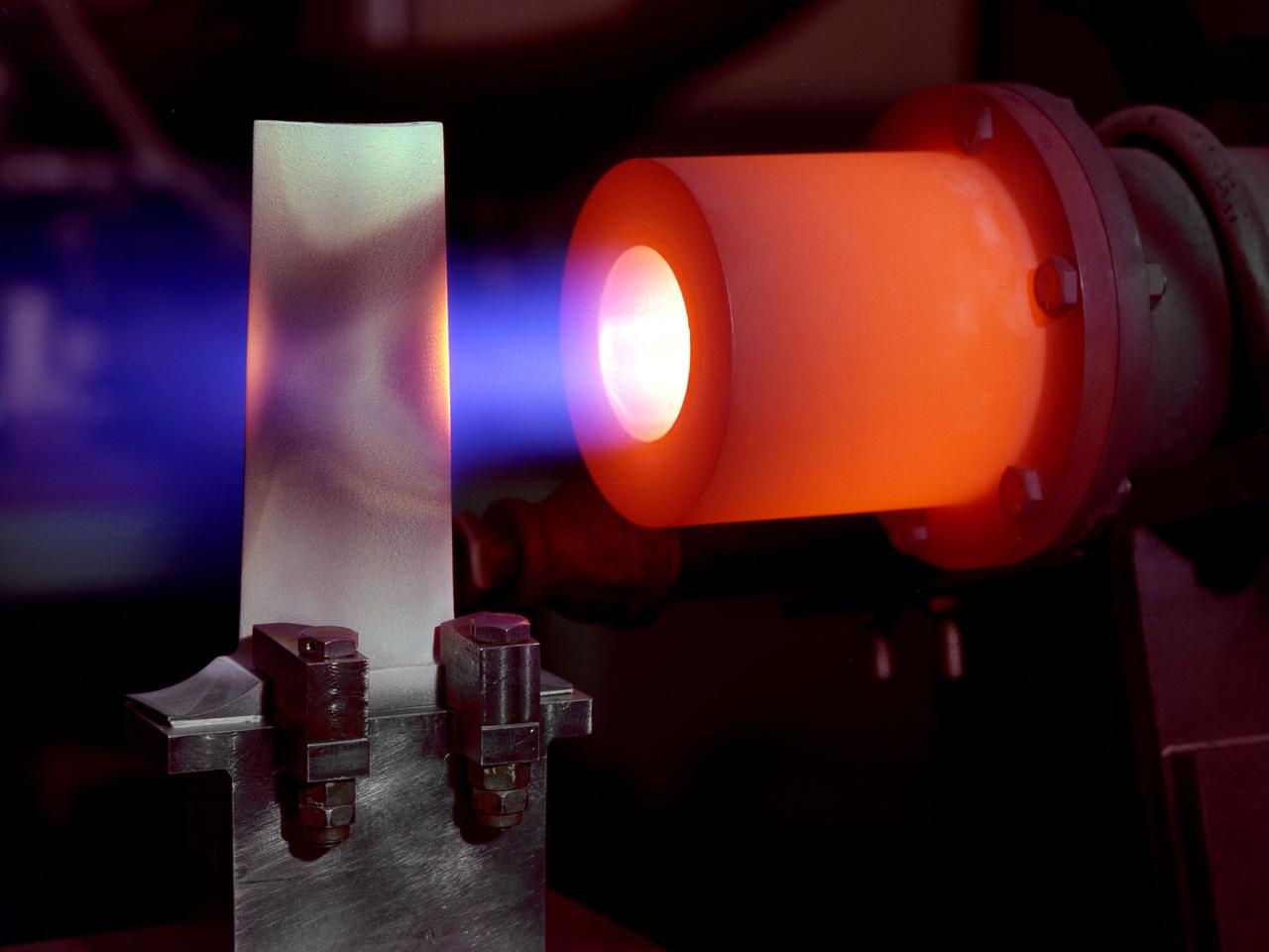
A 1-foot long stator blade with a thermal coating subjected to intense heat in order to test its strength at the National Aeronautics and Space Administration (NASA) Lewis Research Center. Lewis researchers sought to determine optimal types of ceramic coatings to increase the durability of metals. The research was primarily intended to support the design of stator blades for high-performance axial-flow compressor and turbofan engines. The coatings reduced the temperature of the metal and the amount of required cooling. As engines became more and more sophisticated, compressor blades were required to withstand higher and higher temperatures. Lewis researchers developed a dual-layer thermal-barrier coating that could be applied to turbine vanes and blades and combustion liners. This new sprayable thermal-barrier coating was evaluated for its durability, strength, fatigue, and aerodynamic penalties. This hot-gas rig fired the scorching gas at the leading edge of a test blade. The blade was cooled by an internal air flow. The blades were heated at two different velocities during the program. When using Mach 0.3 gases the entire heating and cooling cycle only lasted 30 seconds. The cycle lasted 60 minutes during tests at Mach 1.
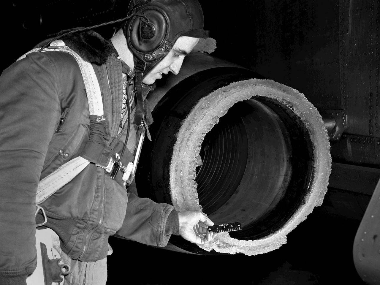
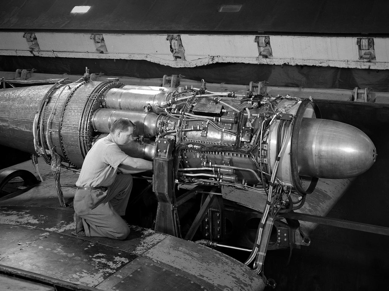
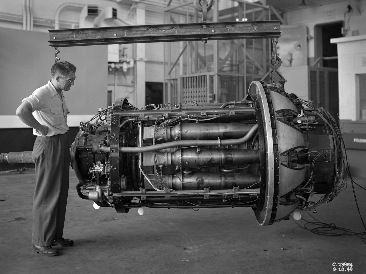
The National Advisory Committee for Aeronautics (NACA) Lewis Flight Propulsion Laboratory conducted an extensive icing research program in the late 1940s that included studies in the Icing Research Tunnel and using specially modified aircraft. One facet of this program was the investigation of the effects of icing on turbojets. Although jet engines allowed aircraft to pass through inclement weather at high rates of speed, ice accumulation was still a concern. The NACA’s B-24M Liberator was initially reconfigured with a General Electric I-16 engine installed in the aircraft’s waist compartment with an air scoop and spray nozzles to produce the artificial icing conditions. The centrifugal engine appeared nearly impervious to the effects of icing. Axial-flow jet engines, however, were much more susceptible to icing damage. The inlet guide vanes were particularly vulnerable, but the cowling’s leading edge, the main bearing supports, and accessory housing could also ice up. If pieces of ice reached the engine’s internal components, the compressor blades could be damaged. To study this phenomenon, a Westinghouse 24C turbojet, seen in this photograph, was installed under the B-24M’s right wing. In January 1948 flight tests of the 24C in icing conditions began. Despite ice buildup into the second stage of the compressor, the engine was able to operate at takeoff speeds. Researchers found the ice on the inlet vanes resulted in half of the engine’s decreased performance.
Researcher Robert Miller led an investigation into the combustor performance of a German Jumo 004 engine at the National Advisory Committee for Aeronautics (NACA) Lewis Flight Propulsion Laboratory. The Jumo 004 powered the world's first operational jet fighter, the Messerschmitt Me 262, beginning in 1942. The Me 262 was the only jet aircraft used in combat during World War II. The eight-stage axial-flow compressor Jumo 004 produced 2000 pounds of thrust. The US Army Air Forces provided the NACA with a Jumo 004 engine in 1945 to study the compressor’s design and performance. Conveniently the engine’s designer Anselm Franz had recently arrived at Wright-Patterson Air Force Base in nearby Dayton, Ohio as part of Project Paperclip. The Lewis researchers used a test rig in the Engine Research Building to analyze one of the six combustion chambers. It was difficult to isolate a single combustor’s performance when testing an entire engine. The combustion efficiency, outlet-temperature distribution, and total pressure drop were measured. The researchers determined the Jumo 004’s maximum performance was 5000 revolutions per minute at a 27,000 foot altitude and 11,000 revolutions per minute at a 45,000 foot altitude. The setup in this photograph was created for a tour of NACA Lewis by members of the Institute of Aeronautical Science on March 22, 1945.
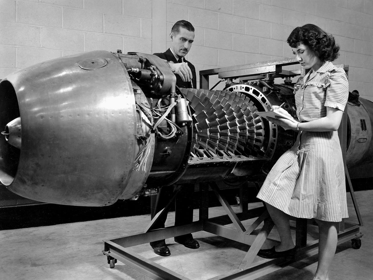
A female computer plotting compressor data in the Engine Research Building at the NACA’s Lewis Flight Propulsion Laboratory. The Computing Section was introduced during World War II to relieve short-handed research engineers of some of the tedious data-taking work. The computers made the initial computations and plotted the data graphically. The researcher then analyzed the data and either summarized the findings in a report or made modifications or ran the test again. With the introduction of mechanical computer systems in the 1950s the female computers learned how to encode the punch cards. As the data processing capabilities increased, fewer female computers were needed. Many left on their own to start families, while others earned mathematical degrees and moved into advanced positions.
N-222; 2 x 2ft Transonic Wind Tunnel is a closed return, variable-density tunnel equipped with an adjustable flexible-wall nozzle and a slotted test section. Airflow is produced by a two-stage, axial-flow compressor powered by four, variable-speed induction motors mounted in tandem, delivering a total of 4,000 horsepower. For conventional, steady-state testing models are generally supported on a sting. Internal, strain-gage balances are used for measuring forces and moments. This facility is also used for panel-flutter testing (one test-section wall is replaced with another containing the test specimen.
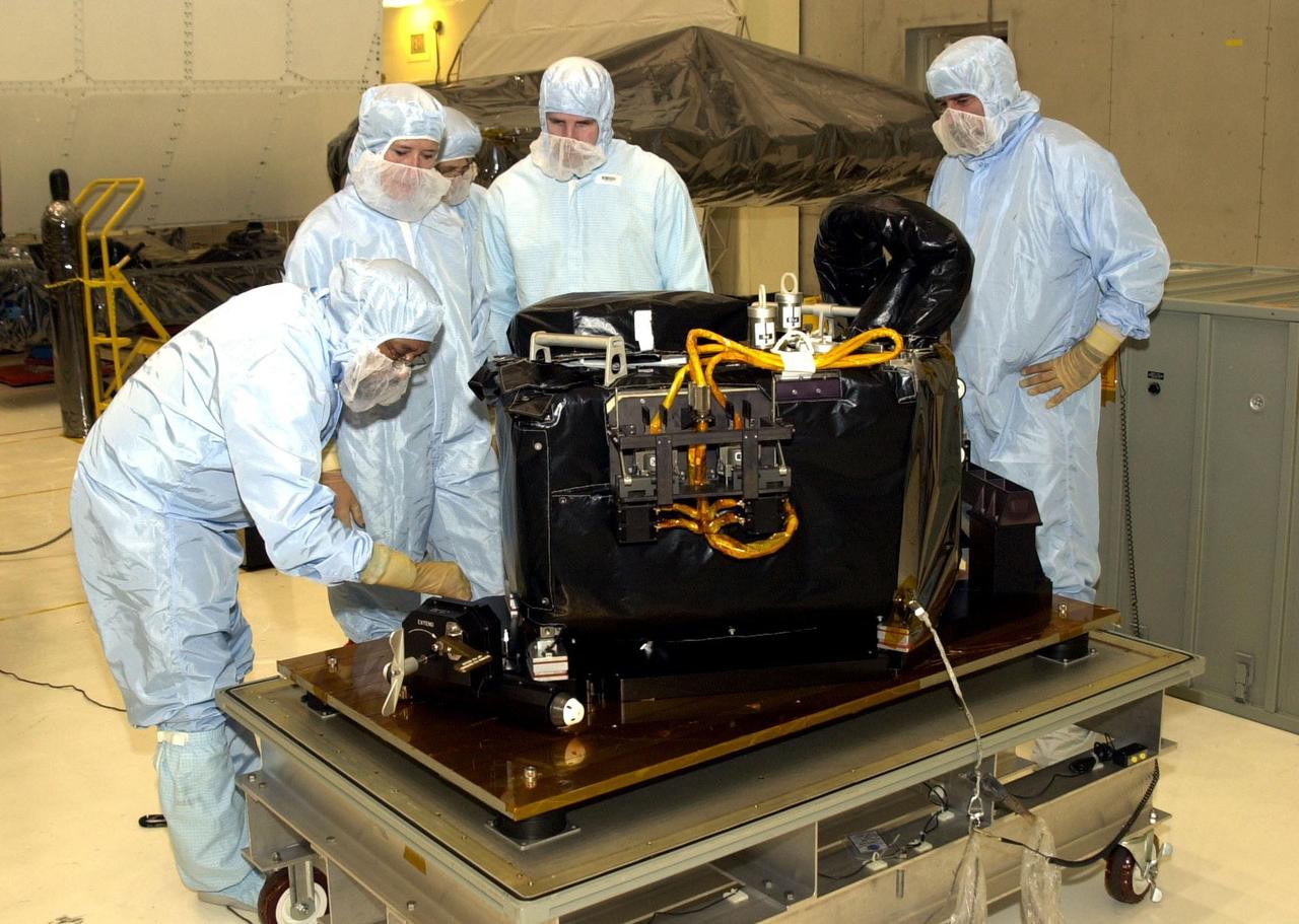
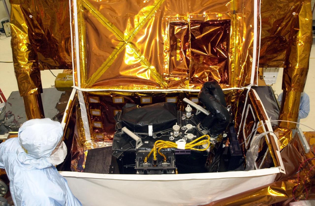
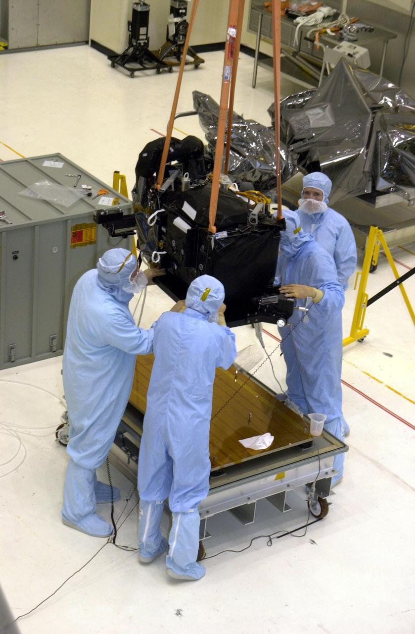
KENNEDY SPACE CENTER, FLA. -- Workers in the Vertical Processing Facility look over the Near Infrared Camera and Multi-Object Spectrometer (NICMOS) Cooling System, part of the payload on mission STS-109, the Hubble Servicing Telescope Mission. NICMOS is a new experimental cooling system consisting of a compressor and tiny turbines. With the experimental cryogenic system, NASA hopes to re-cool the infrared detectors to below -315 degrees F (-193 degrees Celsius). NICMOS II was previously tested aboard STS-95 in 1998. It could extend the life of the Hubble Space Telescope by several years. Astronauts aboard Columbia on mission STS-109 will be replacing the original NICMOS with the newer version. Launch of mission STS-109 is scheduled for Feb. 28, 2002
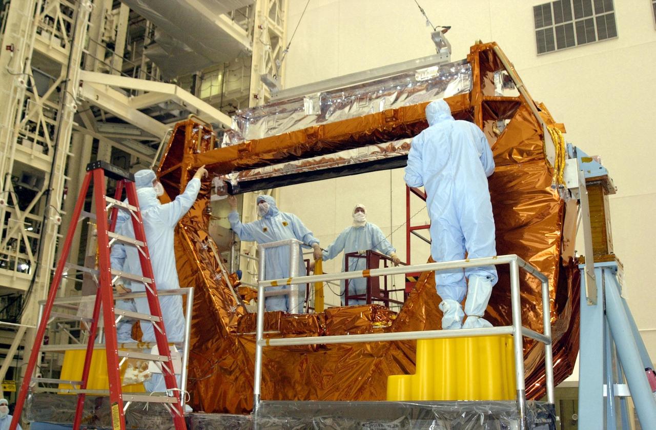
KENNEDY SPACE CENTER, FLA. -- Workers in the Vertical Processing Facility oversee the installation of the NICMOS radiator onto the MULE (Multi-Use Lightweight Equipment) carrier. Part of the payload on mission STS-109, the Near Infrared Camera and Multi-Object Spectrometer (NICMOS) is a new experimental cooling system consisting of a compressor and tiny turbines. With the experimental cryogenic system, NASA hopes to re-cool the infrared detectors to below -315 degrees F (-193 degrees Celsius). NICMOS II was previously tested aboard STS-95 in 1998. NICMOS could extend the life of the Hubble Space Telescope by several years. Astronauts aboard Columbia on mission STS-109 will be replacing the original NICMOS with the newer version. Launch of Columbia on mission STS-109 is scheduled Feb. 28, 2002
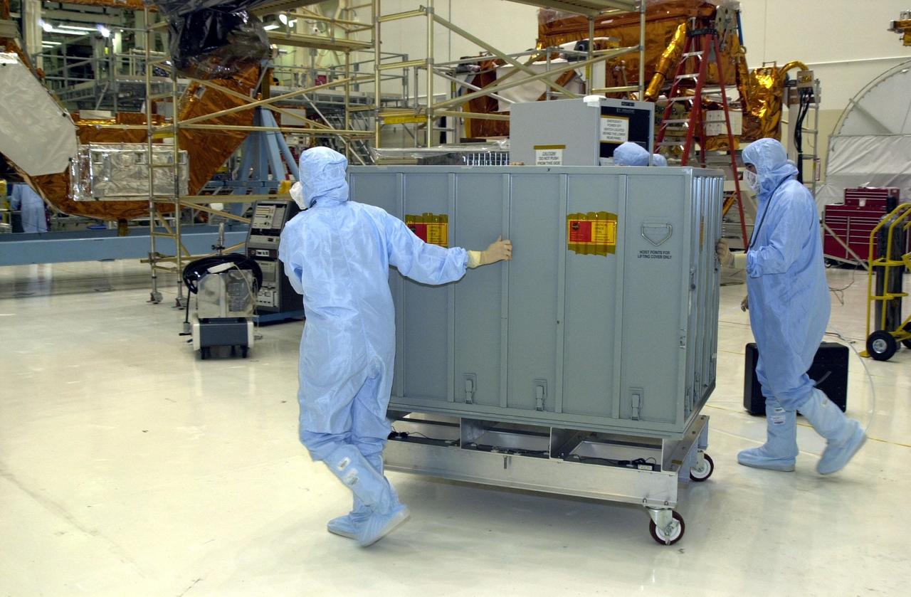
KENNEDY SPACE CENTER, FLA. -- Workers in the Vertical Processing Facility wheel a container with the NICMOS II across the floor. The Near Infrared Camera and Multi-Object Spectrometer (NICMOS) Cooling System is part of the payload on mission STS-109, the Hubble Servicing Telescope Mission. NICMOS is a new experimental cooling system consisting of a compressor and tiny turbines. With the experimental cryogenic system, NASA hopes to re-cool the infrared detectors to below -315 degrees F (-193 degrees Celsius). NICMOS II was previously tested aboard STS-95 in 1998. It could extend the life of the Hubble Space Telescope by several years. Astronauts aboard Columbia on mission STS-109 will be replacing the original NICMOS with the newer version. Launch of mission STS-109 is scheduled for Feb. 28, 2002
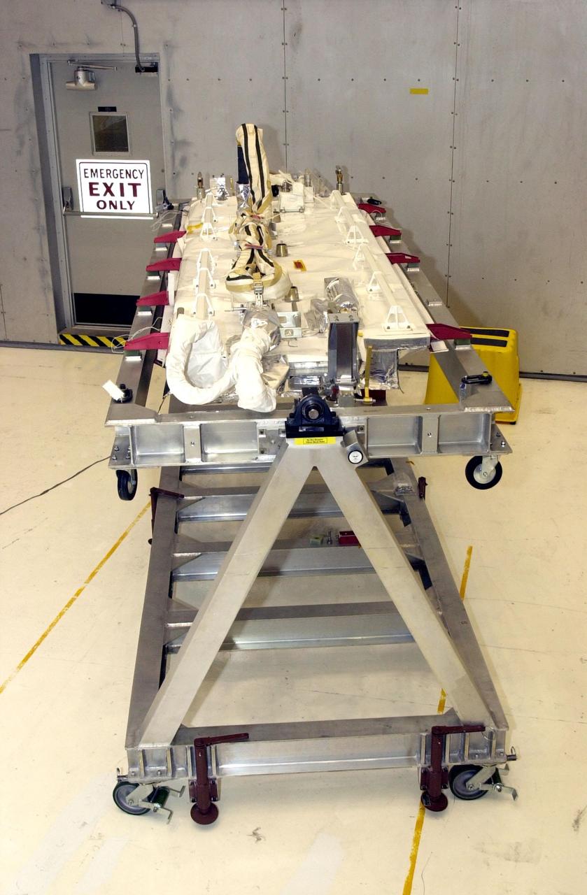
KENNEDY SPACE CENTER, FLA. -- The NICMOS II radiator is ready for checkout in the Vertical Processing Facility. The Near Infrared Camera and Multi-Object Spectrometer (NICMOS) Cooling System is part of the payload on mission STS-109, the Hubble Servicing Telescope mission. NICMOS is a new experimental cooling system consisting of a compressor and tiny turbines. With the experimental cryogenic system, NASA hopes to re-cool the infrared detectors to below -315 degrees F (-193 degrees Celsius). NICMOS II was previously tested aboard STS-95 in 1998. NICMOS could extend the life of the Hubble Space Telescope by several years. Astronauts aboard Columbia on mission STS-109 will be replacing the original NICMOS with the newer version. Launch of Columbia is scheduled Feb. 28, 2002
KENNEDY SPACE CENTER, FLA. -- The Near Infrared Camera and Multi-Object Spectrometer (NICMOS) Cooling System rests inside a protective enclosure on a payload carrier. NICMOS II is part of the payload on mission STS-109, the Hubble Servicing Telescope Mission. It is a new experimental cooling system consisting of a compressor and tiny turbines. With the experimental cryogenic system, NASA hopes to re-cool the infrared detectors to below -315 degrees F (-193 degrees Celsius). NICMOS II was previously tested aboard STS-95 in 1998. It could extend the life of the Hubble Space Telescope by several years. Astronauts aboard Columbia on mission STS-109 will be replacing the original NICMOS with the newer version. Launch of mission STS-109 is scheduled for Feb. 28, 2002
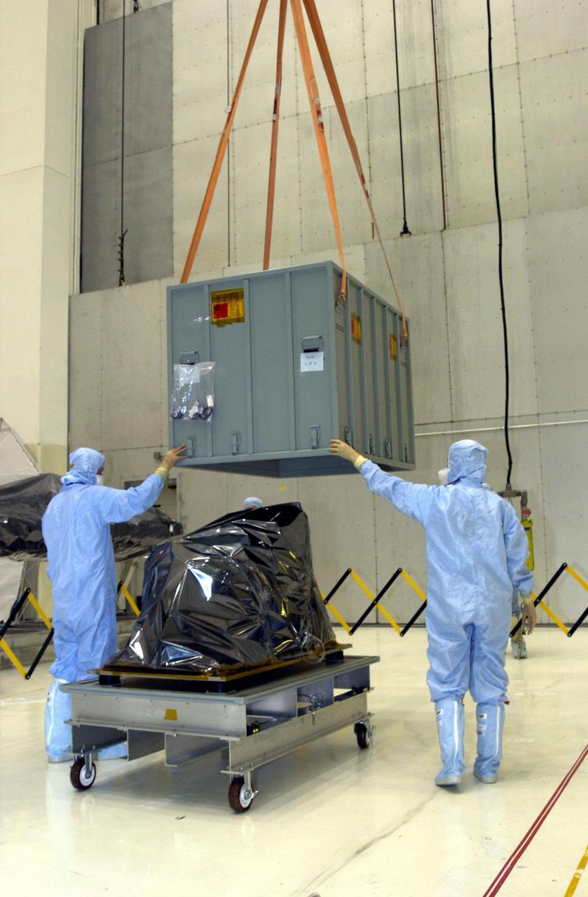
KENNEDY SPACE CENTER, FLA. -- An overhead crane in the Vertical Processing Facility lifts the shipping container from the Near Infrared Camera and Multi-Object Spectrometer (NICMOS) Cooling System, part of the payload on mission STS-109, the Hubble Servicing Telescope Mission. NICMOS is a new experimental cooling system consisting of a compressor and tiny turbines. With the experimental cryogenic system, NASA hopes to re-cool the infrared detectors to below -315 degrees F (-193 degrees Celsius). NICMOS II was previously tested aboard STS-95 in 1998. It could extend the life of the Hubble Space Telescope by several years. Astronauts aboard Columbia on mission STS-109 will be replacing the original NICMOS with the newer version. Launch of mission STS-109 is scheduled for Feb. 28, 2002
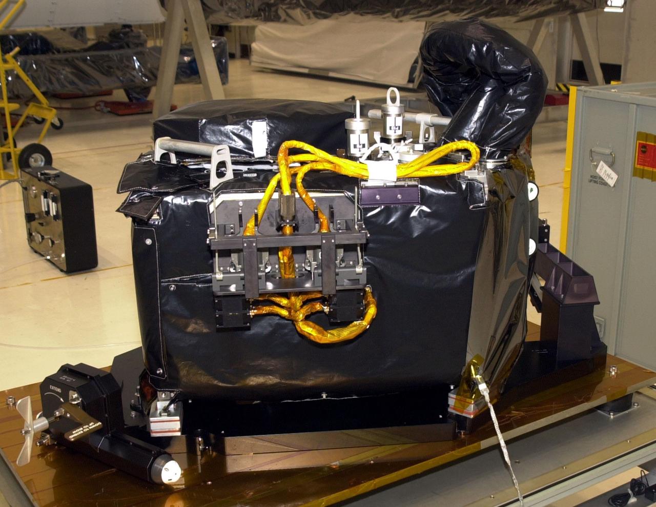
KENNEDY SPACE CENTER, FLA. -- A closeup view of the Near Infrared Camera and Multi-Object Spectrometer (NICMOS) Cooling System, part of the payload on mission STS-109, the Hubble Servicing Telescope Mission. NICMOS II is a new experimental cooling system consisting of a compressor and tiny turbines. With the experimental cryogenic system, NASA hopes to re-cool the infrared detectors to below -315 degrees F (-193 degrees Celsius). NICMOS II was previously tested aboard STS-95 in 1998. It could extend the life of the Hubble Space Telescope by several years. Astronauts aboard Columbia on mission STS-109 will be replacing the original NICMOS with the newer version. Launch of mission STS-109 is scheduled for Feb. 28, 2002

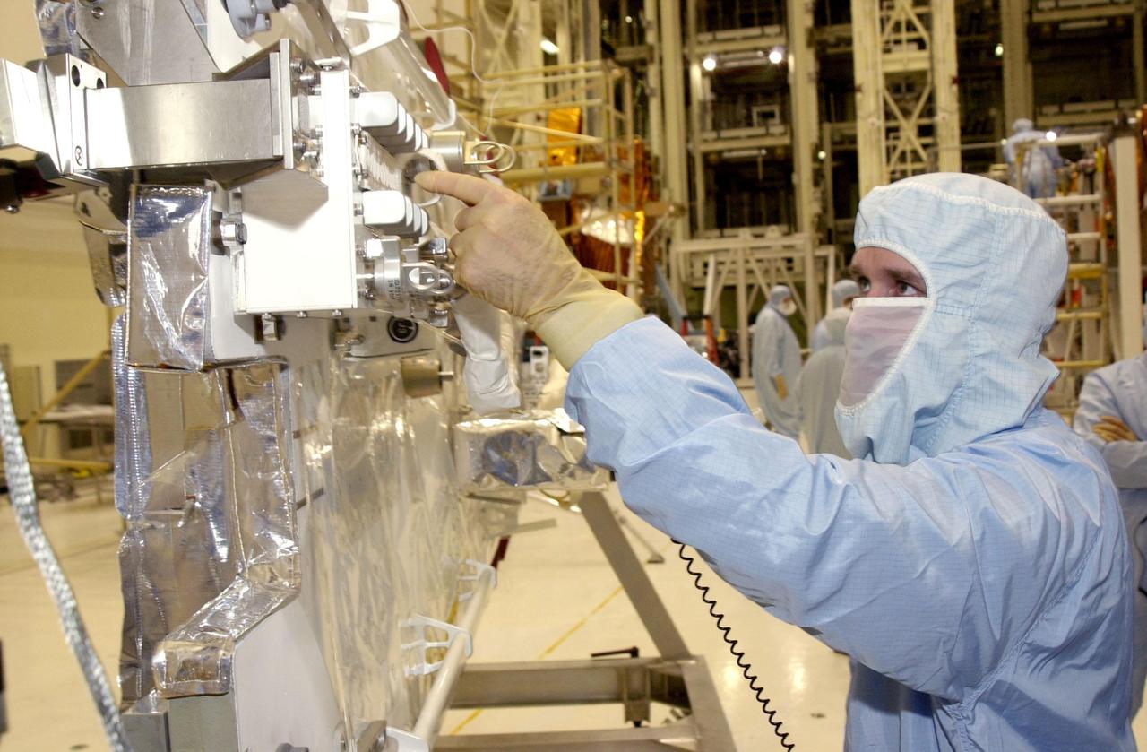
KENNEDY SPACE CENTER, FLA. -- Workers in the Vertical Processing Facility test the Near Infrared Camera and Multi-Object Spectrometer (NICMOS) Cooling System, part of the payload on mission STS-109, the Hubble Servicing Telescope Mission. The worker at right is using a black light. NICMOS II is a new experimental cooling system consisting of a compressor and tiny turbines. With the experimental cryogenic system, NASA hopes to re-cool the infrared detectors to below -315 degrees F (-193 degrees Celsius). NICMOS II was previously tested aboard STS-95 in 1998. It could extend the life of the Hubble Space Telescope by several years. Astronauts aboard Columbia on mission STS-109 will be replacing the original NICMOS with the newer version. Launch of mission STS-109 is scheduled for Feb. 28, 2002
An engineer examines the Coherent Turbulence Rig in the Engine Research Building at the National Aeronautics and Space Administration (NASA) Lewis Research Center. Coherent turbulence occurs when waves of uniform size and alignment are present in airflow. Researchers at NASA Lewis were interested in determining the relation between the size of the waves and their heat transfer properties. The massive 4.25-acre Engine Research Building contains dozens of test cells, test stands, and altitude chambers. A powerful a collection of compressors and exhausters located in the central portion of the basement provides process air and exhaust for these test areas. This system is connected to similar process air systems in the laboratory’s other large test facilities. The Central Control Room coordinates this activity and communicates with the local utilities.
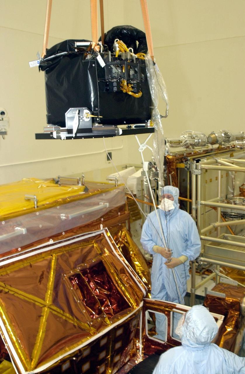
KENNEDY SPACE CENTER, FLA. - A crane in the Vertical Processing Facility lifts the Near Infrared Camera and Multi-Object Spectrometer (NICMOS) Cooling System off the workstand. NICMOS II is part of the payload on mission STS-109, the Hubble Servicing Telescope Mission. It is a new experimental cooling system consisting of a compressor and tiny turbines. With the experimental cryogenic system, NASA hopes to re-cool the infrared detectors to below -315 degrees F (-193 degrees Celsius). NICMOS II was previously tested aboard STS-95 in 1998. It could extend the life of the Hubble Space Telescope by several years. Astronauts aboard Columbia on mission STS-109 will be replacing the original NICMOS with the newer version. Launch of mission STS-109 is scheduled for Feb. 28, 2002
KENNEDY SPACE CENTER, FLA. - In the Vertical Processing Facility, STS-109 Payload Commander John Grunsfeld checks out the NICMOS radiator during crew familiarization activities. Part of the payload on mission STS-109, the Near Infrared Camera and Multi-Object Spectrometer (NICMOS) is a new experimental cooling system consisting of a compressor and tiny turbines. With the experimental cryogenic system, NASA hopes to re-cool the infrared detectors to below -315 degrees F (-193 degrees Celsius). NICMOS II was previously tested aboard STS-95 in 1998. NICMOS could extend the life of the Hubble Space Telescope by several years. Astronauts aboard Columbia on mission STS-109 will be replacing the original NICMOS with the newer version. Launch of Columbia is scheduled Feb. 28, 2002
KENNEDY SPACE CENTER, FLA. -- Workers in the Vertical Processing Facility help guide the Near Infrared Camera and Multi-Object Spectrometer (NICMOS) Cooling System onto a payload carrier. NICMOS II is part of the payload on mission STS-109, the Hubble Servicing Telescope Mission. It is a new experimental cooling system consisting of a compressor and tiny turbines. With the experimental cryogenic system, NASA hopes to re-cool the infrared detectors to below -315 degrees F (-193 degrees Celsius). NICMOS II was previously tested aboard STS-95 in 1998. It could extend the life of the Hubble Space Telescope by several years. Astronauts aboard Columbia on mission STS-109 will be replacing the original NICMOS with the newer version. Launch of mission STS-109 is scheduled for Feb. 28, 2002
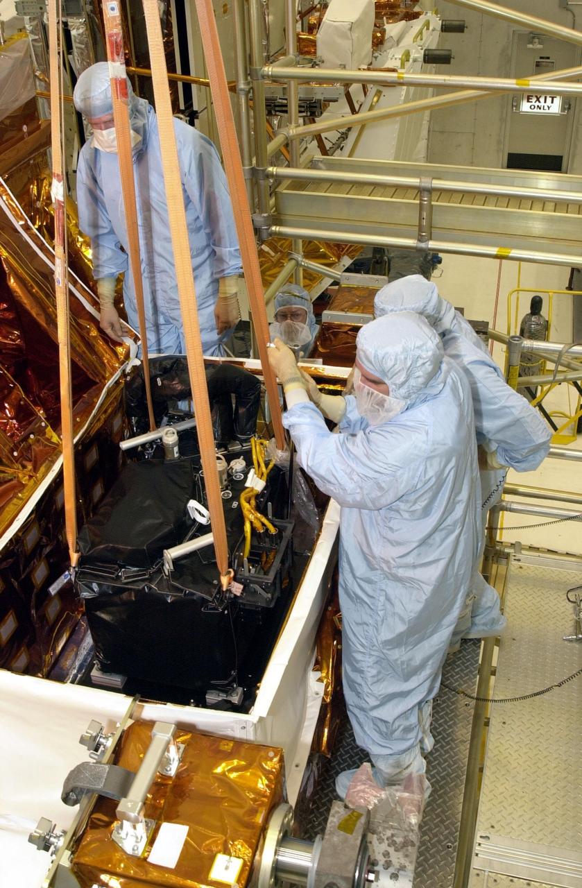
KENNEDY SPACE CENTER, FLA. -- In the Vertical Processing Facility, workers help guide the Near Infrared Camera and Multi-Object Spectrometer (NICMOS) Cooling System into an protective enclosure on a payload carrier. NICMOS II is part of the payload on mission STS-109, the Hubble Servicing Telescope Mission. It is a new experimental cooling system consisting of a compressor and tiny turbines. With the experimental cryogenic system, NASA hopes to re-cool the infrared detectors to below -315 degrees F (-193 degrees Celsius). NICMOS II was previously tested aboard STS-95 in 1998. It could extend the life of the Hubble Space Telescope by several years. Astronauts aboard Columbia on mission STS-109 will be replacing the original NICMOS with the newer version. Launch of mission STS-109 is scheduled for Feb. 28, 2002
A General Electric TG-100A seen from the rear in the test section of the Altitude Wind Tunnel at the National Advisory Committee for Aeronautics (NACA) Lewis Flight Propulsion Laboratory in Cleveland, Ohio. The Altitude Wind Tunnel was used to study almost every model of US turbojet that emerged in the 1940s, as well as some ramjets and turboprops. In the early 1940s the military was interested in an engine that would use less fuel than the early jets but would keep up with them performance-wise. Turboprops seemed like a plausible solution. They could move a large volume of air and thus required less engine speed and less fuel. Researchers at General Electric’s plant in Schenectady, New York worked on the turboprop for several years in the 1930s. They received an army contract in 1941 to design a turboprop engine using an axial-flow compressor. The result was the 14-stage TG-100, the nation's first turboprop aircraft engine. Development of the engine was slow, however, and the military asked NACA Lewis to analyze the engine’s performance. The TG-100A was tested in the Altitude Wind Tunnel and it was determined that the compressors, combustion chamber, and turbine were impervious to changes in altitude. The researchers also established the optimal engine speed and propeller angle at simulated altitudes up to 35,000 feet. Despite these findings, development of the TG-100 was cancelled in May 1947. Twenty-eight of the engines were produced, but they were never incorporated into production aircraft.

A mechanic works on a General Electric I-40 turbojet at the National Advisory Committee for Aeronautics (NACA) Lewis Flight Propulsion Laboratory. The military selected General Electric’s West Lynn facility in 1941 to secretly replicate the centrifugal turbojet engine designed by British engineer Frank Whittle. General Electric’s first attempt, the I-A, was fraught with problems. The design was improved somewhat with the subsequent I-16 engine. It was not until the engine's next reincarnation as the I-40 in 1943 that General Electric’s efforts paid off. The 4000-pound thrust I-40 was incorporated into the Lockheed Shooting Star airframe and successfully flown in June 1944. The Shooting Star became the US’s first successful jet aircraft and the first US aircraft to reach 500 miles per hour. The NACA’s Lewis Flight Propulsion Laboratory studied all of General Electric’s centrifugal turbojets both during World War II and afterwards. The entire Shooting Star aircraft was investigated in the Altitude Wind Tunnel during 1945. The researchers studied the engine compressor performance, thrust augmentation using a water injection, and compared different fuel blends in a single combustor. The mechanic in this photograph is inserting a combustion liner into one of the 14 combustor cans. The compressor, which is not yet installed in this photograph, pushed high pressure air into these combustors. There the air mixed with the fuel and was heated. The hot air was then forced through a rotating turbine that powered the engine before being expelled out the nozzle to produce thrust.
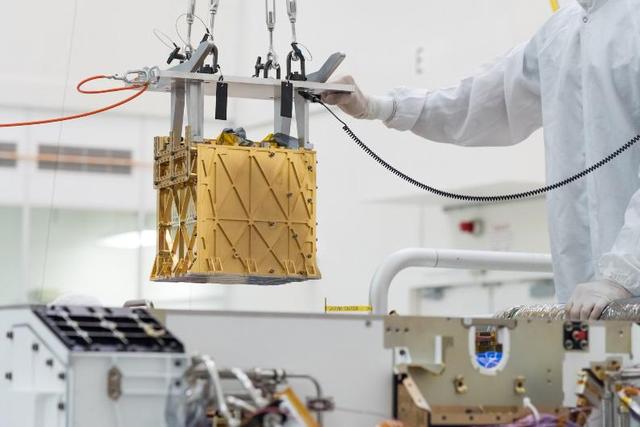
MOXIE (Mars Oxygen In-Situ Resource Utilization Experiment) was launched aboard NASA's Perseverance rover to test a technology for extracting oxygen from the Red Planet's carbon dioxide-rich atmosphere. Audio of MOXIE's air compressor at work on Mars was captured by the microphone on Perseverance's SuperCam instrument on May 27, 2021, the 96th day of the rover's mission. Since Perseverance landed on Mars in 2021, MOXIE generated a total of 122 grams of oxygen – about what a small dog breathes in 10 hours. At its most efficient, MOXIE was able to produce 12 grams of oxygen an hour – twice as much as NASA's original goals for the instrument – at 98% purity or better. On its final, 16th run, on Aug. 7, 2023, the instrument made 9.8 grams of oxygen. MOXIE successfully completed all of its technical requirements and was operated at a variety of conditions throughout a full Mars year, allowing the instrument's developers to learn a great deal about the technology. MOXIE produces molecular oxygen through an electrochemical process that separates one oxygen atom from each molecule of carbon dioxide pumped in from Mars' thin atmosphere. As these gases flow through the system, they're analyzed to check the purity and quantity of oxygen produced. While many of Perseverance's experiments are addressing primary science goals, MOXIE was focused on future human exploration. MOXIE served as the first-ever demonstration of technology that humans could use to survive on, and leave, the Red Planet. An oxygen-producing system could help future missions in various ways, but the most important of them would be as a source of rocket propellant, which would be required in industrial quantities to launch rockets with astronauts for their return trip home. Rather than bringing large quantities of oxygen with them to Mars, future astronauts could live off the land, using materials they find on the planet's surface to survive. This concept – called in-situ resource utilization, or ISRU – has evolved into a growing area of research. A key objective for Perseverance's mission on Mars is astrobiology, including the search for signs of ancient microbial life. The rover will characterize the planet's geology and past climate, pave the way for human exploration of the Red Planet, and be the first mission to collect and cache Martian rock and regolith (broken rock and dust). Subsequent NASA missions, in cooperation with ESA (European Space Agency), would send spacecraft to Mars to collect these sealed samples from the surface and return them to Earth for in-depth analysis. The Mars 2020 Perseverance mission is part of NASA's Moon to Mars exploration approach, which includes Artemis missions to the Moon that will help prepare for human exploration of the Red Planet. Audio file available at https://photojournal.jpl.nasa.gov/catalog/PIA26041
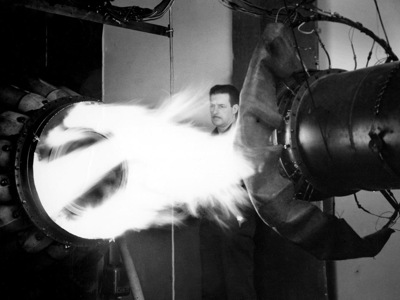
A mechanic watches the firing of a General Electric I-40 turbojet at the National Advisory Committee for Aeronautics (NACA) Lewis Flight Propulsion Laboratory. The military selected General Electric’s West Lynn facility in 1941 to secretly replicate the centrifugal turbojet engine designed by British engineer Frank Whittle. General Electric’s first attempt, the I-A, was fraught with problems. The design was improved somewhat with the subsequent I-16 engine. It was not until the engine's next reincarnation as the I-40 in 1943 that General Electric’s efforts paid off. The 4000-pound thrust I-40 was incorporated into the Lockheed Shooting Star airframe and successfully flown in June 1944. The Shooting Star became the US’s first successful jet aircraft and the first US aircraft to reach 500 miles per hour. NACA Lewis studied all of General Electric’s centrifugal turbojet models during the 1940s. In 1945 the entire Shooting Star aircraft was investigated in the Altitude Wind Tunnel. Engine compressor performance and augmentation by water injection; comparison of different fuel blends in a single combustor; and air-cooled rotors were studied. The mechanic in this photograph watches the firing of a full-scale I-40 in the Jet Propulsion Static Laboratory. The facility was quickly built in 1943 specifically in order to test the early General Electric turbojets. The I-A was secretly analyzed in the facility during the fall of 1943.
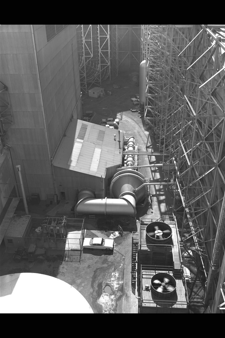
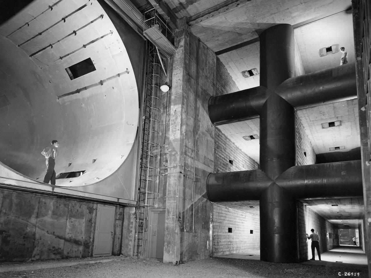
The 10- by 10-Foot Supersonic Wind Tunnel at the NACA Lewis Flight Propulsion Laboratory was built under the Congressional Unitary Plan Act which coordinated wind tunnel construction at the NACA, Air Force, industry, and universities. The 10- by 10, which began operation in 1956, was the largest of the three NACA tunnels built under the act. Researchers could test engines up to five feet in diameter in the 10- by 10-foot test section. A 250,000-horsepower axial-flow compressor fan can generate airflows up to Mach 3.5 through the test section. The incoming air must be dehumidified and cooled so that the proper conditions are present for the test. A large air dryer with 1,890 tons of activated alumina soaks up 1.5 tons of water per minute from the airflow. A cooling apparatus equivalent to 250,000 household air conditioners is used to cool the air. The air heater is located just upstream from the test section. Natural gas is combusted in the tunnel to increase the air temperature. The system could only be employed when the tunnel was run in its closed-circuit propulsion mode.
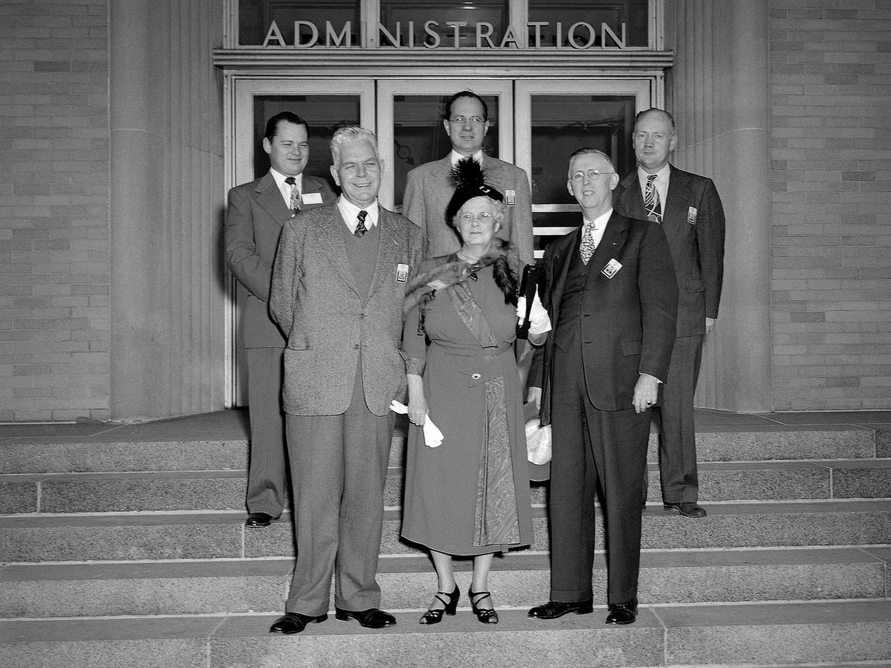
Myrtle Lewis and three of her sons visit the National Advisory Committee for Aeronautics (NACA) Lewis Flight Propulsion Laboratory in Cleveland, Ohio. The Flight Propulsion Research Laboratory was renamed in Lewis’ honor in September 1948. Lewis served as the NACA’s Director of Aeronautical Research for over 20 years. Lewis joined the NACA as Executive Officer in 1919 and was named Director of Aeronautical Research in 1924. In this role Lewis served as the liaison between the Executive Committee and the research laboratories. His most important accomplishment may have been the investigative tours of German research facilities in 1936 and 1939. The visits resulted in the NACA’s physical expansion and the broadening of its scope of research. Lewis did not take a day of leave between the Pearl Harbor attack and the Armistice, but began suffering health problems in 1945. He was forced to retire two years later and passed in July 1948. Front row, left to right: Lewis Director Raymond Sharp, Mrs. Lewis, NACA Executive Secretary John Victory; back row: Executive Officer Robert Sessions, Armand Lewis, Harvey Lewis, and George Lewis II. Harvey and George Lewis II were employed at NACA Lewis in the Instrument Service and Applied Compressor sections, respectively.
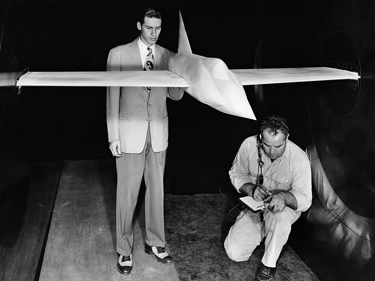
A .10-scale model of Convair’s XF-102 in the 8- by 6-Foot Supersonic Wind Tunnel at the National Advisory Committee for Aeronautics (NACA) Lewis Flight Propulsion Laboratory for jet exit studies. The XF-102 was a prototype of the F-102 Delta Dagger. The F-102 served as an interceptor against long range bombers from the Soviet Union. The aircraft was powered by a Pratt and Whitney J57 turbojet. The first prototype crashed two weeks after is first flight on October 24, 1953, just months after this photograph. Engineers then incorporated the fixed-wing design to reduce drag at supersonic speeds. The production model F-102 became the first delta-wing supersonic aircraft in operation. The 8- by 6-Foot Supersonic Wind Tunnel is used to study propulsion systems, including inlets and exit nozzles, combustion fuel injectors, flame holders, exit nozzles, and controls on ramjet and turbojet engines. Flexible sidewalls alter the tunnel’s nozzle shape to vary the Mach number during operation. A seven-stage axial compressor, driven by three electric motors that yield a total of 87,000 horsepower, generates air speeds from Mach 0.36 to 2.0.
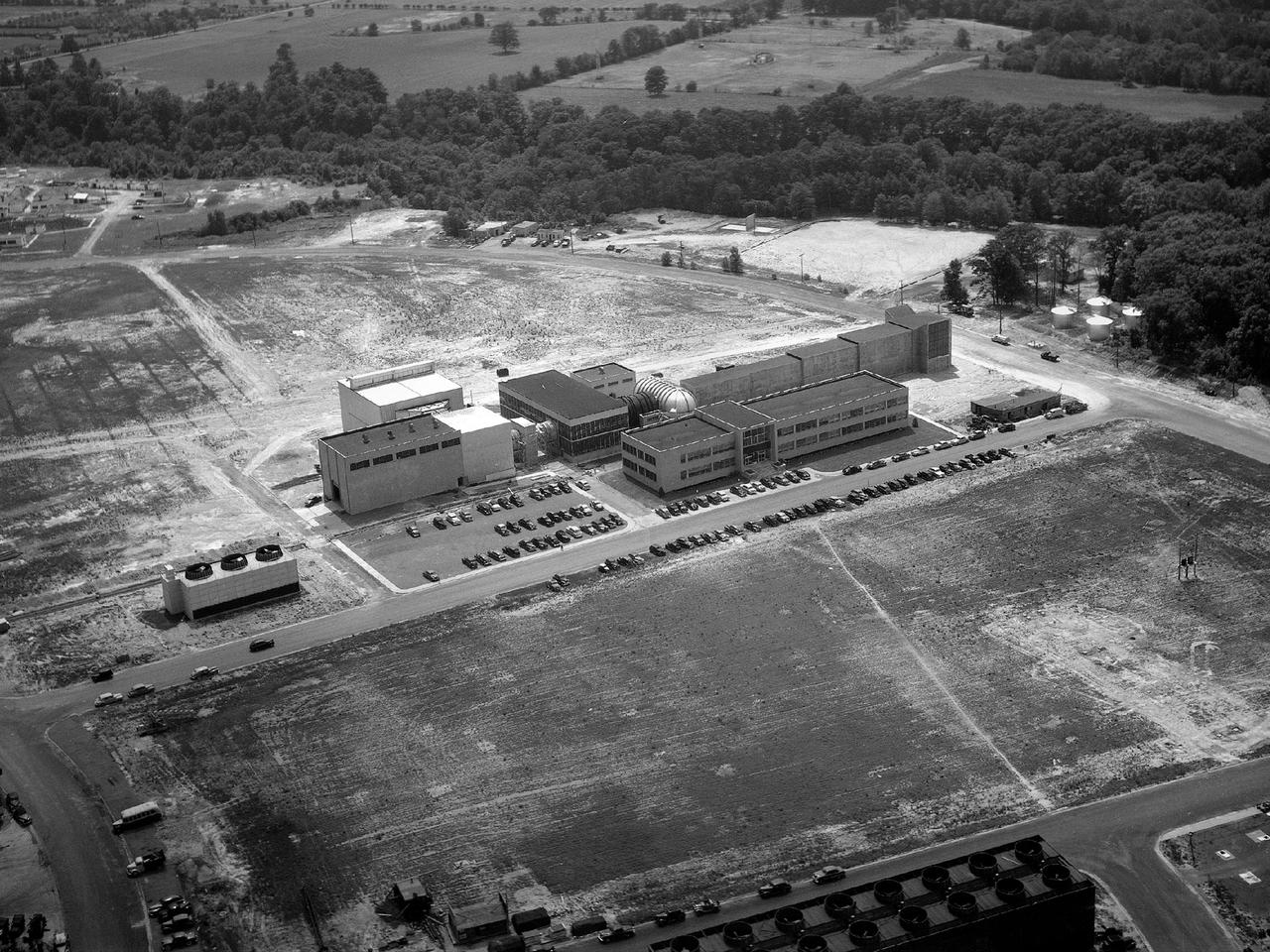
Aerial view of the 8- by 6-Foot Supersonic Wind Tunnel in its original configuration at the National Advisory Committee for Aeronautics (NACA) Lewis Flight Propulsion Laboratory. The 8- by 6 was the laboratory’s first large supersonic wind tunnel. It was also the NACA’s most powerful supersonic tunnel, and its first facility capable of running an engine at supersonic speeds. The 8- by 6-foot tunnel has been used to study inlets and exit nozzles, fuel injectors, flameholders, exit nozzles, and controls on ramjet and turbojet propulsion systems. The 8- by 6 was originally an open-throat and non-return tunnel. This meant that the supersonic air flow was blown through the test section and out the other end into the atmosphere. In this photograph, the three drive motors in the structure at the left supplied power to the seven-stage axial-flow compressor in the light-colored structure. The air flow passed through flexible walls which were bent to create the desired speed. The test article was located in the 8- by 6-foot stainless steel test section located inside the steel pressure chamber at the center of this photograph. The tunnel dimensions were then gradually increased to slow the air flow before it exited into the atmosphere. The large two-story building in front of the tunnel was used as office space for the researchers.
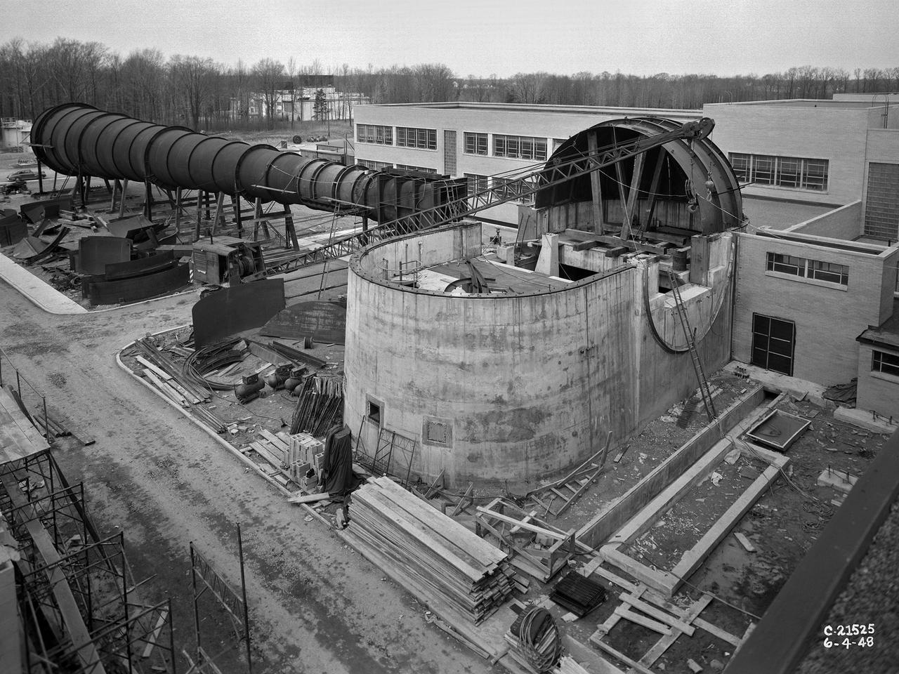
The 8- by 6-Foot Supersonic Wind Tunnel at the National Advisory Committee for Aeronautics (NACA) Lewis Flight Propulsion Laboratory was the nation’s largest supersonic facility when it began operation in April 1949. The emergence of new propulsion technologies such as turbojets, ramjets, and rockets during World War II forced the NACA and the aircraft industry to develop new research tools. In late 1945 the NACA began design work for new large supersonic wind tunnels at its three laboratories. The result was the 4- by 4-Foot Supersonic Wind Tunnel at Langley Memorial Aeronautical Laboratory, 6- by 6-foot supersonic wind tunnel at Ames Aeronautical Laboratory, and the largest facility, the 8- by 6-Foot Supersonic Wind Tunnel in Cleveland. The two former tunnels were to study aerodynamics, while the 8- by 6 facility was designed for supersonic propulsion. The 8- by 6-Foot Supersonic Wind Tunnel was used to study propulsion systems, including inlets and exit nozzles, combustion fuel injectors, flame holders, exit nozzles, and controls on ramjet and turbojet engines. Flexible sidewalls alter the tunnel’s nozzle shape to vary the Mach number during operation. A seven-stage axial compressor, driven by three electric motors that yield a total of 87,000 horsepower, generates air speeds from Mach 0.36 to 2.0. A section of the tunnel is seen being erected in this photograph.
A researcher in the Supercharger Research Division at the National Advisory Committee for Aeronautics (NACA) Aircraft Engine Research Laboratory measures the blade thickness on a supercharger. Superchargers were developed at General Electric used to supply additional air to reciprocating engines. The extra air resulted in increased the engine’s performance, particularly at higher altitudes. The Aircraft Engine Research Laboratory had an entire division dedicated to superchargers during World War II. General Electric developed the supercharger in response to a 1917 request from the NACA to develop a device to enhance high-altitude flying. The supercharger pushed larger volumes of air into the engine manifold. The extra oxygen allowed the engine to operate at its optimal sea-level rating even when at high altitudes. Thus, the aircraft could maintain its climb rate, maneuverability and speed as it rose higher into the sky. NACA work on the supercharger ceased after World War II due to the arrival of the turbojet engine. The Supercharger Research Division was disbanded in October 1945 and reconstituted as the Compressor and Turbine Division.
The 8- by 6-Foot Supersonic Wind Tunnel at the National Advisory Committee for Aeronautics (NACA) Lewis Flight Propulsion Laboratory was the largest supersonic wind tunnel in the nation at the time and the only one able to test full-scale engines at supersonic speeds. The 8- by 6 was designed as a non-return and open-throat tunnel. A large compressor created the air flow at one end of the tunnel, squeezed the flow to increase its velocity just before the test section, then reduced the velocity, and expelled it into the atmosphere at the other end of the tunnel. This design worked well for initial aerodynamic testing, but the local community was literally rattled by the noise and vibrations when researchers began running engines in the test section in January 1950. The NACA’s most modern wind tunnel was referred to as “an 87,000-horsepower bugle aimed at the heart of Cleveland.” NACA Lewis responded to the complaints by adding an acoustic housing at the end of the tunnel to dampen the noise. The structure included resonator chambers and a reinforced concrete muffler structure. Modifications continued over the years. A return leg was added, and a second test section, 9 -by 15-foot, was incorporated in the return leg in the 1960s. Since its initial operation in 1948, the 8- by 6-foot tunnel has been aggressively used to support the nation's aeronautics and space programs for the military, industry, and academia.
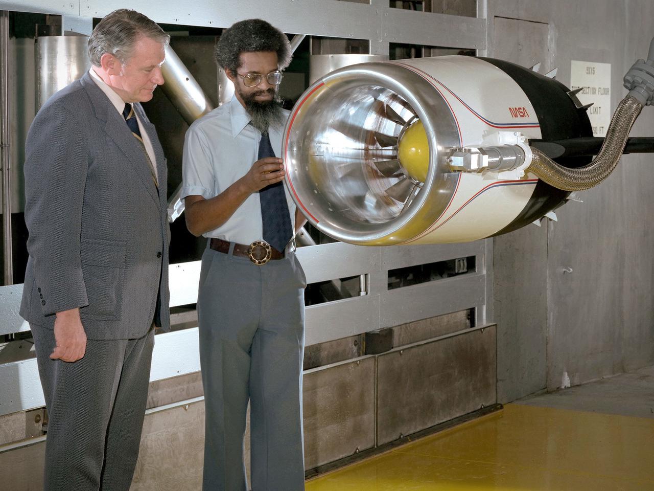
Center Director John McCarthy, left, and researcher Al Johns pose with a one-third scale model of a Grumman Aerospace tilt engine nacelle for Vertical and Short Takeoff and Landing (V/STOL) in the 9- by 15-Foot Low Speed Wind Tunnel at the National Aeronautics and Space Administration (NASA) Lewis Research Center. Lewis researchers had been studying tilt nacelle and inlet issues for several years. One area of concern was the inlet flow separation during the transition from horizontal to vertical flight. The separation of air flow from the inlet’s internal components could significantly stress the fan blades or cause a loss of thrust. In 1978 NASA researchers Robert Williams and Al Johns teamed with Grumman’s H.C. Potonides to develop a series of tests in the Lewis 9- by 15-foot tunnel to study a device designed to delay the flow separation by blowing additional air into the inlet. A jet of air, supplied through the hose on the right, was blown over the inlet surfaces. The researchers verified that the air jet slowed the flow separation. They found that the blowing on boundary layer control resulted in a doubling of the angle-of-attack and decreases in compressor blade stresses and fan distortion. The tests were the first time the concept of blowing air for boundary layer control was demonstrated. Boundary layer control devices like this could result in smaller and lighter V/STOL inlets.
A General Electric TG-180 turbojet installed in the Altitude Wind Tunnel at the National Advisory Committee for Aeronautics (NACA) Lewis Flight Propulsion Laboratory. In 1943 the military asked General Electric to develop an axial-flow jet engine which became the TG-180. The military understood that the TG-180 would not be ready during World War II but recognized the axial-flow compressor’s long-term potential. Although the engine was bench tested in April 1944, it was not flight tested until February 1946. The TG-180 was brought to the Altitude Wind Tunnel in 1945 for a series of investigations. The studies, which continued intermittently into 1948, analyzed an array of performance issues. NACA modifications steadily improved the TG-180’s performance, including the first successful use of an afterburner. The Lewis researchers studied a 29-inch diameter afterburner over a range of altitude conditions using several different types of flameholders and fuel systems. Lewis researchers concluded that a three-stage flameholder with its largest stage upstream was the best burner configuration. Although the TG-180 (also known as the J35) was not the breakthrough engine that the military had hoped for, it did power the Douglas D-558-I Skystreak to a world speed record on August 20, 1947. The engines were also used on the Republic F-84 Thunderjet and the Northrup F-89 Scorpion.

One of the two primary coolers at the Propulsion Systems Laboratory at the National Advisory Committee for Aeronautics (NACA) Lewis Flight Propulsion Laboratory. Engines could be run in simulated altitude conditions inside the facility’s two 14-foot-diameter and 24-foot-long test chambers. The Propulsion Systems Laboratory was the nation’s only facility that could run large full-size engine systems in controlled altitude conditions. At the time of this photograph, construction of the facility had recently been completed. Although not a wind tunnel, the Propulsion Systems Laboratory generated high-speed airflow through the interior of the engine. The air flow was pushed through the system by large compressors, adjusted by heating or refrigerating equipment, and de-moisturized by air dryers. The exhaust system served two roles: reducing the density of the air in the test chambers to simulate high altitudes and removing hot gases exhausted by the engines being tested. It was necessary to reduce the temperature of the extremely hot engine exhaust before the air reached the exhauster equipment. As the air flow exited through exhaust section of the test chamber, it entered into the giant primary cooler seen in this photograph. Narrow fins or vanes inside the cooler were filled with water. As the air flow passed between the vanes, its heat was transferred to the cooling water. The cooling water was cycled out of the system, carrying with it much of the exhaust heat.
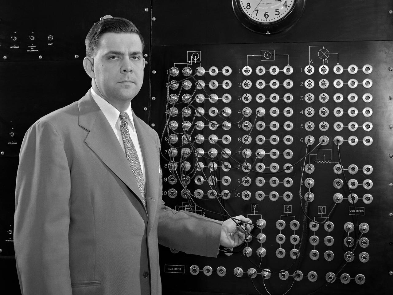
Harry Mergler stands at the control board of a differential analyzer in the new Instrument Research Laboratory at the National Advisory Committee for Aeronautics (NACA) Lewis Flight Propulsion Laboratory. The differential analyzer was a multi-variable analog computation machine devised in 1931 by Massachusetts Institute of Technology researcher and future NACA Committee member Vannevar Bush. The mechanical device could solve computations up to the sixth order, but had to be rewired before each new computation. Mergler modified Bush’s differential analyzer in the late 1940s to calculate droplet trajectories for Lewis’ icing research program. In four days Mergler’s machine could calculate what previously required weeks. NACA Lewis built the Instrument Research Laboratory in 1950 and 1951 to house the large analog computer equipment. The two-story structure also provided offices for the Mechanical Computational Analysis, and Flow Physics sections of the Physics Division. The division had previously operated from the lab’s hangar because of its icing research and flight operations activities. Mergler joined the Instrument Research Section of the Physics Division in 1948 after earning an undergraduate degree in Physics from the Case Institute of Technology. Mergler’s focus was on the synthesis of analog computers with the machine tools used to create compressor and turbine blades for jet engines.
The Fan Noise Test Facility built at the Lewis Research Center to obtain far-field noise data for the National Aeronautics and Space Administration (NASA) and General Electric Quiet Engine Program. The engine incorporated existing noise reduction methods into an engine of similar power to those that propelled the Boeing 707 or McDonnell-Douglas DC-8 airliner. The new the low-bypass ratio turbofan engines of the 1960s were inherently quieter than their turbojet counterparts, researchers had a better grasp of the noise generation problem, and new acoustic technologies had emerged. Lewis contracted General Electric in 1969 to build and aerodynamically test three experimental engines with 72-inch diameter fans. The engines were then brought to Lewis and tested with an acoustically treated nacelle. This Fan Noise Test Facility was built off of the 10- by 10-Foot Supersonic Wind Tunnel’s Main Compressor and Drive Building. Lewis researchers were able to isolate the fan’s noise during these initial tests by removing the core of the engine. The Lewis test rig drove engines to takeoff tip speeds of 1160 feet per second. The facility was later used to test a series of full-scale model fans and fan noise suppressors to be used with the quiet engine. NASA researchers predicted low-speed single-stage fans without inlet guide vanes and with large spacing between rotors and stators would be quieter. General Electric modified a TF39 turbofan engine by removing the the outer protion of the fan and spacing the blade rows of the inner portion. The tests revealed that the untreated version of the engine generated less noise than was anticipated, and the acoustically treated nacelle substantially reduced engine noise.

Title: W-8 Fan Acoustic Casing Treatment Test on the Source Diagnostic Test Rotor Alone Hardware Program: Advanced Air Vehicles Program (AAVP) Project: Advanced Air Transport Technology (AATT) Sub-project: Aircraft Noise Reduction (ANR) Weekly Highlight: · Acoustic Casing Treatment Testing Completed in the W-8 Single Stage Axial Compressor Facility: Testing of Acoustic Casing Treatments on the Source Diagnostic Test (SDT) rotor alone hardware which had begun in early January was completed on Thursday, February 16th. Four different over-the-rotor acoustic casing treatment concepts were tested along with two baseline configurations. Testing included steady-aerodynamic measurements of fan performance, hotfilm turbulence measurements, and inlet acoustic measurements with an in-duct array. These measurements will be used to assess the aerodynamic and acoustic impact of fan acoustic casing treatments on a high bypass ratio fan at TRL 3. This test was the last of 3 planned tests of potential over-the-rotor acoustic casing treatments. The first treatment test was completed in the Normal Incidence Tube (NIT) at Langley Research Center (LaRC) in Fall 2015 and the second was completed on the Advanced Noise Control Fan (ANCF) in the Aero-Acoustic Propulsion Laboratory (AAPL) in Winter 2016. This work is supported by the Aircraft Noise Reduction (ANR) subproject of the Advanced Air Transport Technology (AATT) Project. (POC: LTV/ Rick Bozak 3-5160)
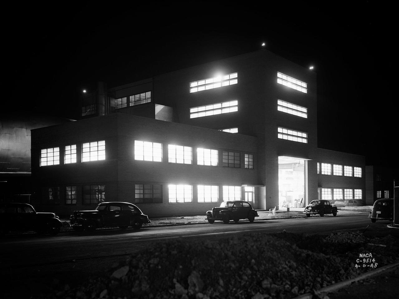
The Altitude Wind Tunnel (AWT) during one of its overnight runs at the National Advisory Committee for Aeronautics (NACA) Aircraft Engine Research Laboratory in Cleveland, Ohio. The AWT was run during night hours so that its massive power loads were handled when regional electric demands were lowest. At the time the AWT was among the most complex wind tunnels ever designed. In order to simulate conditions at high altitudes, NACA engineers designed innovative new systems that required tremendous amounts of electricity. The NACA had an agreement with the local electric company that it would run its larger facilities overnight when local demand was at its lowest. In return the utility discounted its rates for the NACA during those hours. The AWT could produce wind speeds up to 500 miles per hour through its 20-foot-diameter test section at the standard operating altitude of 30,000 feet. The airflow was created by a large fan that was driven by an 18,000-horsepower General Electric induction motor. The altitude simulation was accomplished by large exhauster and refrigeration systems. The cold temperatures were created by 14 Carrier compressors and the thin atmosphere by four 1750-horsepower exhausters. The first and second shifts usually set up and broke down the test articles, while the third shift ran the actual tests. Engineers would often have to work all day, then operate the tunnel overnight, and analyze the data the next day. The night crew usually briefed the dayshift on the tests during morning staff meetings.
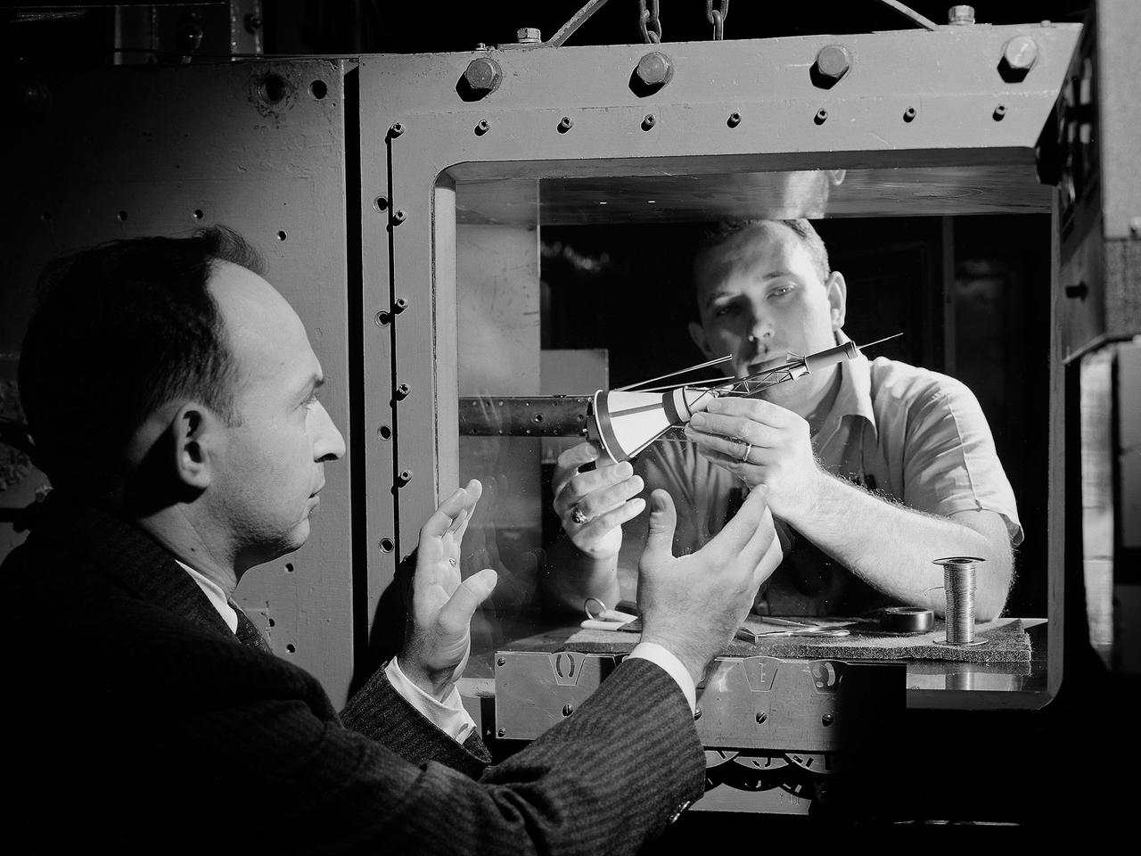
National Aeronautics and Space Administration (NASA) researchers install a small-scale model of the capsule for Project Mercury in the 1- by 1-Foot Supersonic Wind Tunnel at the Lewis Research Center. NASA Lewis conducted a variety of tests for Project Mercury, including retrorocket calibration, escape tower engine performance, and separation of the capsule from simulated Atlas and Redstone boosters. The test of this capsule and escape tower model in the 1- by 1-foot tunnel were run in January and February 1960. The 1-by 1-Foot Supersonic Wind Tunnel had a 15-inch long test section, seen here, that was one foot wide and one foot high. The sides were made of glass to allow cameras to capture the supersonic air flow over the models. The tunnel could generate air flows from Mach 1.3 to 3.0. At the time, it was one of nine small supersonic wind tunnels at Lewis. These tunnels used the exhauster and compressor equipment of the larger facilities. The 1- by 1 tunnel, which began operating in the early 1950s, was built inside a test cell in the expansive Engine Research Building. During the 1950s the 1- by 1 was used to study a variety of inlets, nozzles, and cones for missiles and scramjets. The Mercury capsule tests were among the last at the facility for many years. The tunnel was mothballed in 1960. The 1- by 1 was briefly restored in 1972, then brought back online for good in 1979. The facility has maintained a brisk operating schedule ever since.
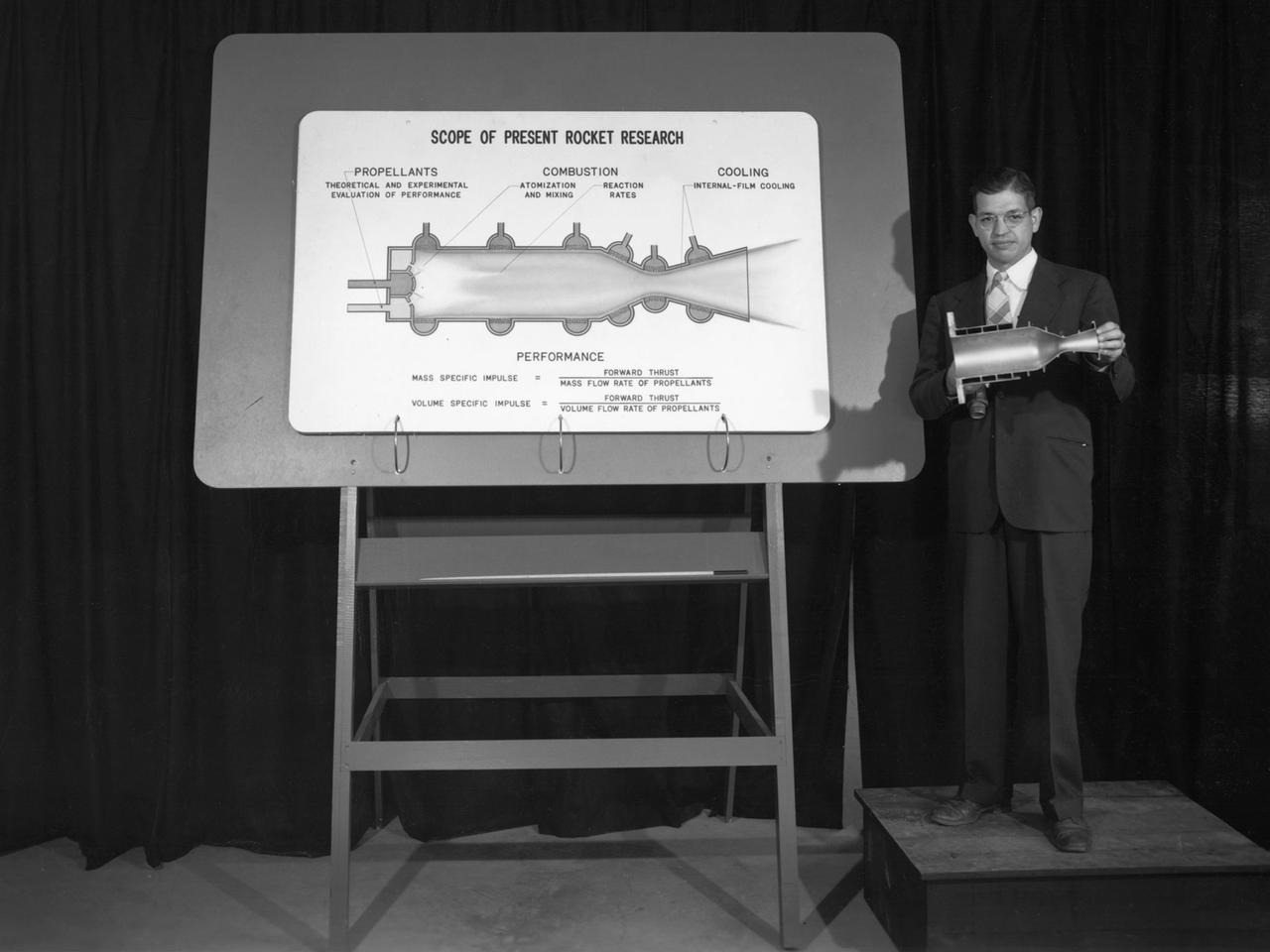
Researcher John Sloop briefs visitors on his latest rocket engine research during the 1947 Inspection at the National Advisory Committee for Aeronautics (NACA) Lewis Flight Propulsion Laboratory. The NACA had been hosting annual Aircraft Engineering Conferences, better known as Inspections, since 1926. Individuals from the manufacturing industry, military, and university settings were invited to tour the NACA laboratories. There were a series of stops on the tour, mostly at test facilities, where researchers would brief the group on the latest efforts in their particular field. The Inspections grew in size and scope over the years and by the mid-1940s required multiple days. The three-day 1947 Inspection was the first time the event was held at NACA Lewis. Over 800 scientists, industrialists, and military leaders attended the three-day event. Talks were given at the Altitude Wind Tunnel, Four Burner Area, Engine Research Building, and other facilities. An array of topics were discussed, including full-scale engine testing, ramjets, axial-flow compressors, turbojets, fuels, icing, and materials. The NACA Lewis staff and their families were able to view the same presentations after the Inspection was over. Sloop, a researcher in the Fuels and Thermodynamics Division, briefed visitors on NACA Lewis’ early research in rocket engine propellants, combustion, and cooling. This early NACA Lewis work led to the development of liquid hydrogen as a viable propellant in the late 1950s.
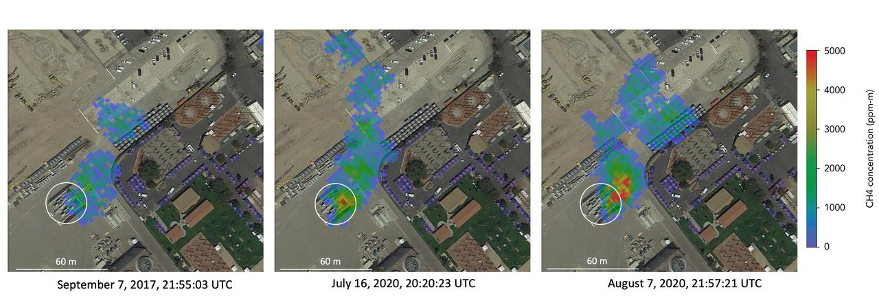
Atmospheric methane is a potent greenhouse gas and an important contributor to air quality. Future instruments on orbiting satellites can help improve our understanding of important methane emission sources. NASA conducts periodic methane studies using the next-generation Airborne Visible/Infrared Imaging Spectrometer (AVIRIS-NG) instrument. These studies are determining the locations and magnitudes of the largest methane emission sources across California, including those associated with landfills, refineries, dairies, wastewater treatment plants, oil and gas fields, power plants, and natural gas infrastructure. These three images show concentrations of methane in a natural gas plume relative to background air measured by AVIRIS-NG, overlaid on true-color land surface images (source: Google Earth). The aircraft was flying at an altitude of about 10,000 feet (3,000 meters) above ground level and the AVIRIS-NG image pixels are each about 10 feet (3 meters) across. The plume shape varies with changing emission rate, wind speed and direction. The methane plume originates from a compressor — circled in each image — at Valley Generating Station, a natural gas-fired power plant near Los Angeles. The color scale indicates the concentration of methane in each pixel relative to background methane concentrations in the surrounding atmosphere. The plume was initially detected by a single overflight in September 2017 but assumed at the time to be due to normal operations (intermittent venting). The plume was detected by AVIRIS-NG again on six flights in July-August 2020. https://photojournal.jpl.nasa.gov/catalog/PIA24019
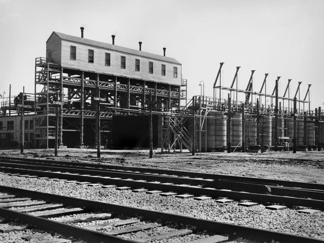
An ammonia oxidation plant at the Plum Brook Ordnance Works near Sandusky, Ohio, which later became the National Aeronautics and Space Administration’s (NASA) Plum Brook Station. During World War II the ordnance works produced trinitroluene (TNT), dinitrotoluene (DNT), and pentolite which were crated and shipped to an arsenal in Ravenna, Ohio. There, the explosives were packed into shells and sent to Allied forces overseas. Plum Brook was the third largest producer of TNT during World War II. Toluene, sulfuric acid, and nitric acid were used to manufacture the TNT. Nitric Acid is made by oxidizing ammonia, adding water, and concentrating it. The facility in this photograph was used for this oxidation. The structure included air compressors, filters, aftercoolers, power recovery systems, air receivers, heaters, ammonia gasifiers, gas mixers, cooler condensers, absorption columns, and bleaching columns. The Plum Brook Ordnance Works was shut down immediately after the war and remained vacant for the next ten years. NASA’s predecessor, the National Advisory Committee for Aeronautics (NACA), acquired the 500 acres of the site in 1955 to build a nuclear test reactor. By 1963, the agency had acquired the entire 9000 acres from the Army. Almost all of the military facilities were removed in the early 1960s. Plum Brook Station contained over 30 test facilities at its peak in the late 1960s. Today there are four major facilities in operation.
A 3670-horsepower Armstrong-Siddeley Python turboprop being prepared for tests in the Altitude Wind Tunnel at the National Advisory Committee for Aeronautics (NACA) Lewis Flight Propulsion Laboratory. In 1947 Lewis researcher Walter Olsen led a group of representatives from the military, industry, and the NACA on a fact finding mission to investigate the technological progress of British turbojet manufacturers. Afterwards several British engines, including the Python, were brought to Cleveland for testing in Lewis’s altitude facilities. The Python was a 14-stage axial-flow compressor turboprop with a fixed-area nozzle and contra-rotating propellers. Early turboprops combined the turbojet and piston engine technologies. They could move large quantities of air so required less engine speed and thus less fuel. This was very appealing to the military for some applications. The military asked the NACA to compare the Python’s performance at sea to that at high altitudes. The NACA researchers studied the Python in the Altitude Wind Tunnel from July 1949 through January 1950. It was the first time the tunnel was used to study an engine with the sole purpose of learning about, not improving it. They analyzed the engine’s dynamic response using a frequency response method at altitudes between 10,000 to 30,000 feet. Lewis researchers found that they could predict the dynamic response characteristics at any altitude from the data obtained from any other specific altitude. This portion of the testing was completed during a single test run.
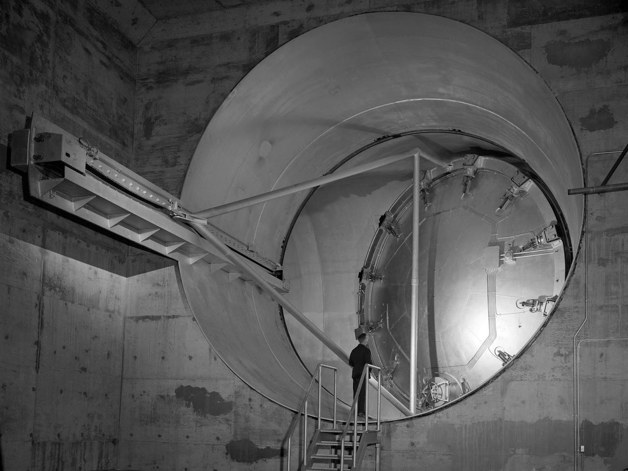
A 24-foot diameter swing valve is seen in an open position inside the new 10- by 10-Foot Supersonic Wind Tunnel at the National Advisory Committee for Aeronautics (NACA) Lewis Flight Propulsion Laboratory. The 10- by 10 was the most powerful propulsion wind tunnel in the nation. After over three years of construction the tunnel was ready to conduct its first tests in early 1956. The 10- by 10-foot tunnel was part of Congress’ Unitary Plan Act which coordinated wind tunnel construction at the NACA, Air Force, industry, and universities. The 10- by 10 was the largest of the three NACA tunnels built under the act. This large swinging valve is critical to the operation of the facility. In one position the valve seals off the tunnel exhaust, making the tunnel a closed circuit, which is used for aerodynamic testing of models. In its other position, the valve acts as a seal across the tunnel and leaves the tunnel exhaust open. This arrangement is used when engines are fired. The air going through the tunnel is taken from the atmosphere and returned to the atmosphere after one pass through the tunnel. Engines up to five feet in diameter can be tested in the 10- by 10-foot test section. Air flows up to Mach 3.5 can be fed through the test section by a 250,000-horsepower axial-flow compressor fan. The incoming air must be dehumidified and cooled so that the proper conditions are present for the test. A large air dryer with 1,890 tons of activated alumina soaks up 1.5 tons of water per minute from the air flow. A cooling apparatus equivalent to 250,000 household air conditioners is used to cool the air.