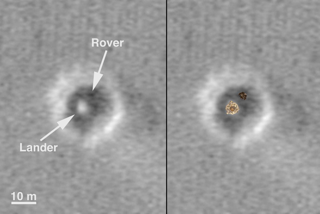
Comparison of a Computer Graphic Model of the Opportunity Lander and Rover with MOC Orbital Image
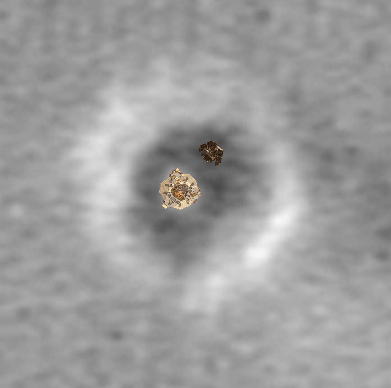
Top View of a Computer Graphic Model of the Opportunity Lander and Rover
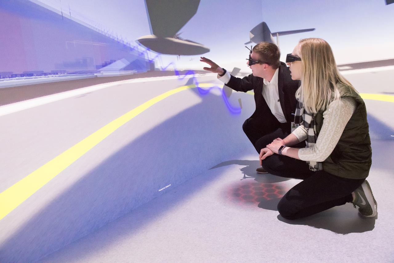
Computer Automatic Virtual Environment, CAVE Tours to Mark the 30th Anniversary of the Graphics and Visualization Lab, GVIS
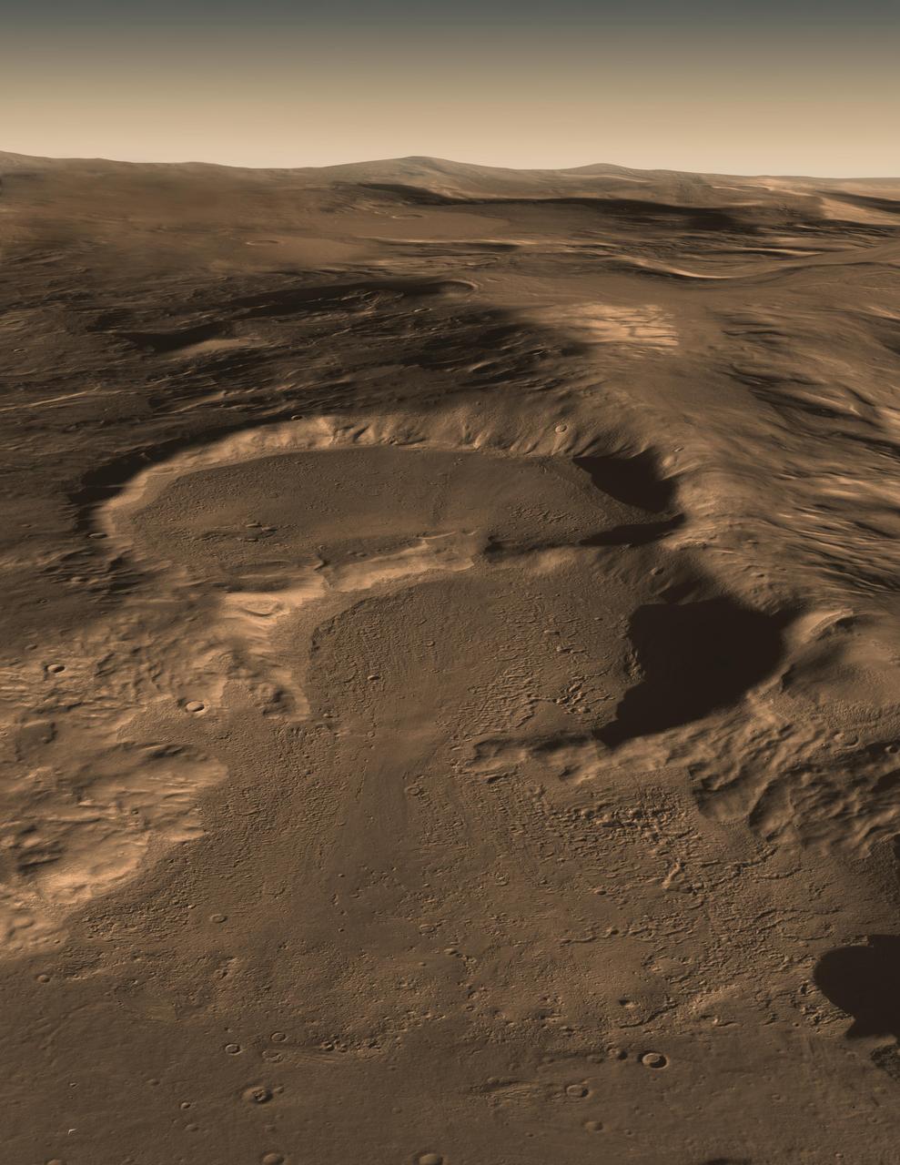
This computer graphic image shows three craters in the eastern Hellas region of Mars containing concealed glaciers detected by radar.
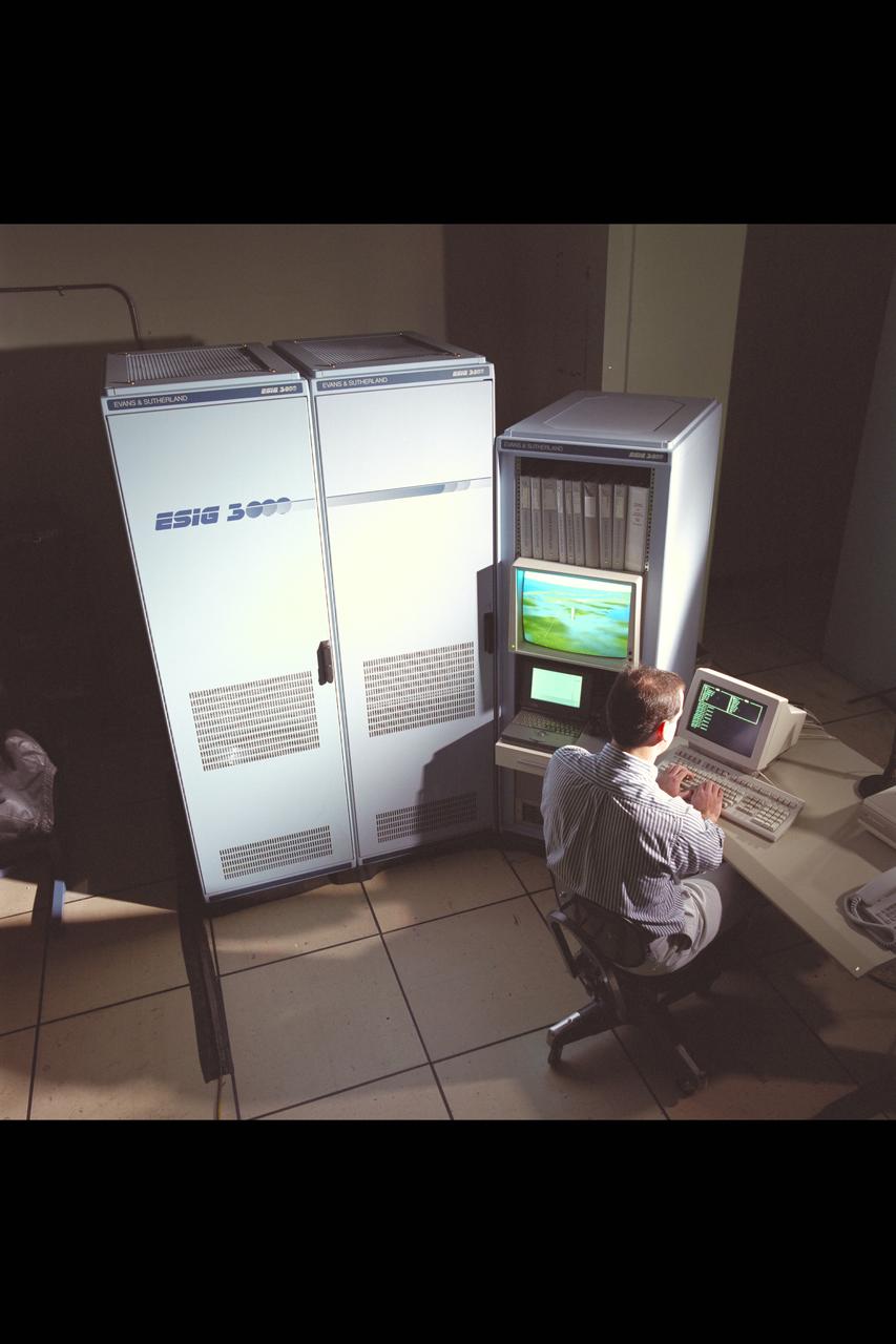
ESIG-3000 Computer for VMS graphic creation with Chris Sweeney

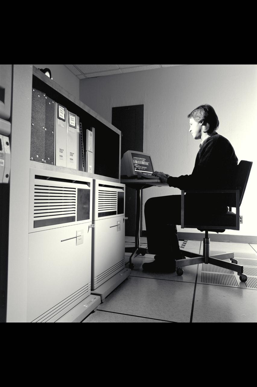
BetaCom 700H computer graphic systems in N-233 with Thomas Crawford

ESIG-300 Computer for VMS graphic creation with Chris Sweeney
VAX-6000 Computer for VMS graphic creation with Fred Kull
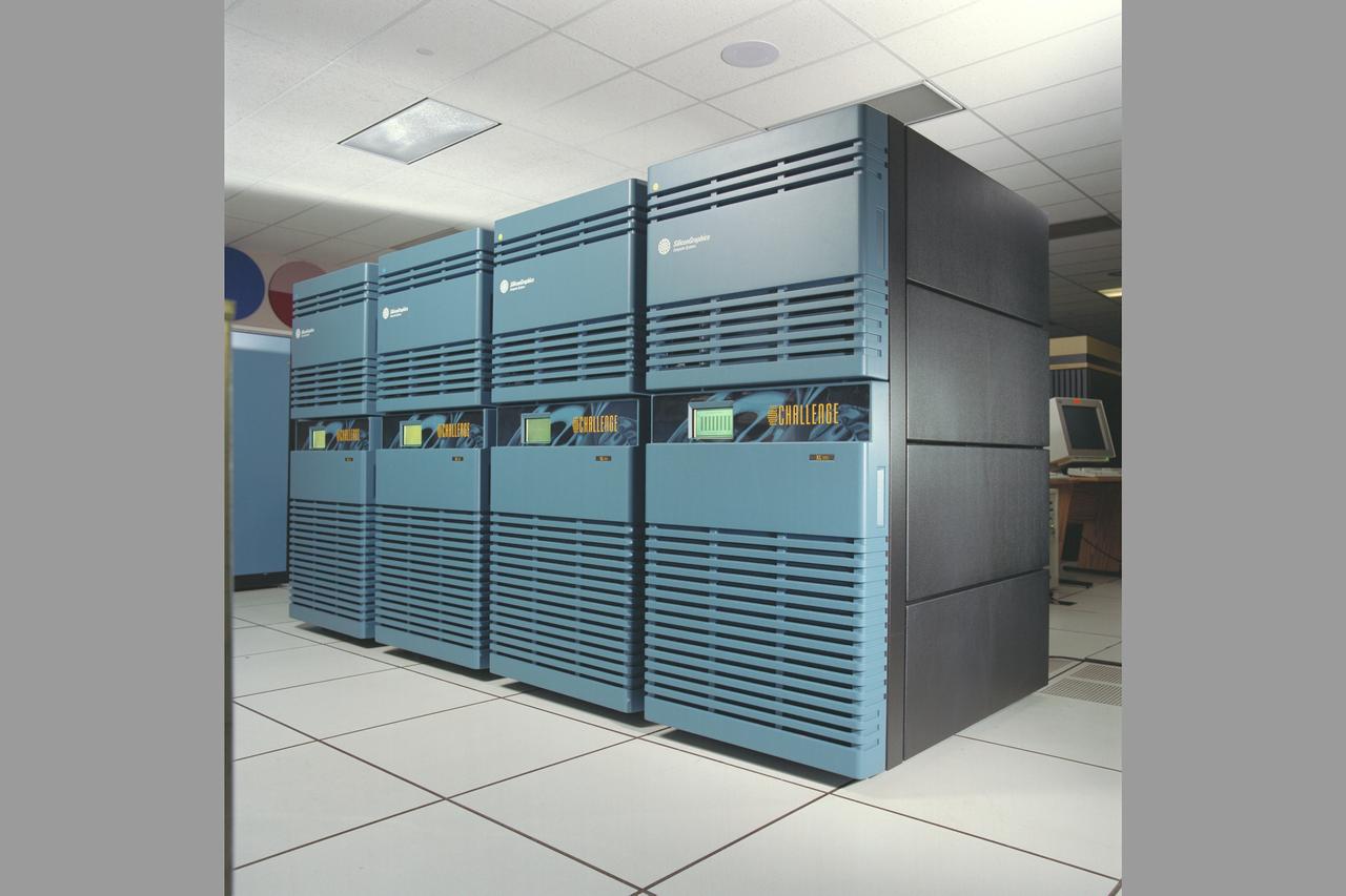
N-258 NAS (Numerical Aerodynamic Simulation) Computers - Silicon Graphics Power Challenge
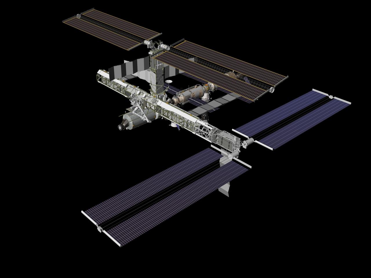
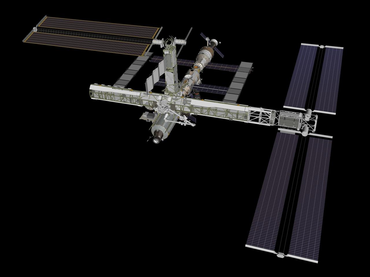
JSC2006-E-38949 (August 2006) --- Computer generated graphic of the International Space Station configuration after STS-115/12A with the addition of the P3/P4 integrated truss segments.
JSC2006-E-38950 (August 2006) --- Computer generated graphic of the International Space Station configuration after STS-116/12A.1 with the addition of the P5 integrated truss segment.
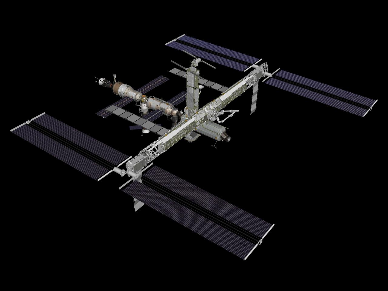
JSC2006-E-38951 (August 2006) --- Computer generated graphic of the International Space Station configuration after STS-117/13A with the addition of S3/S4 integrated truss segments.
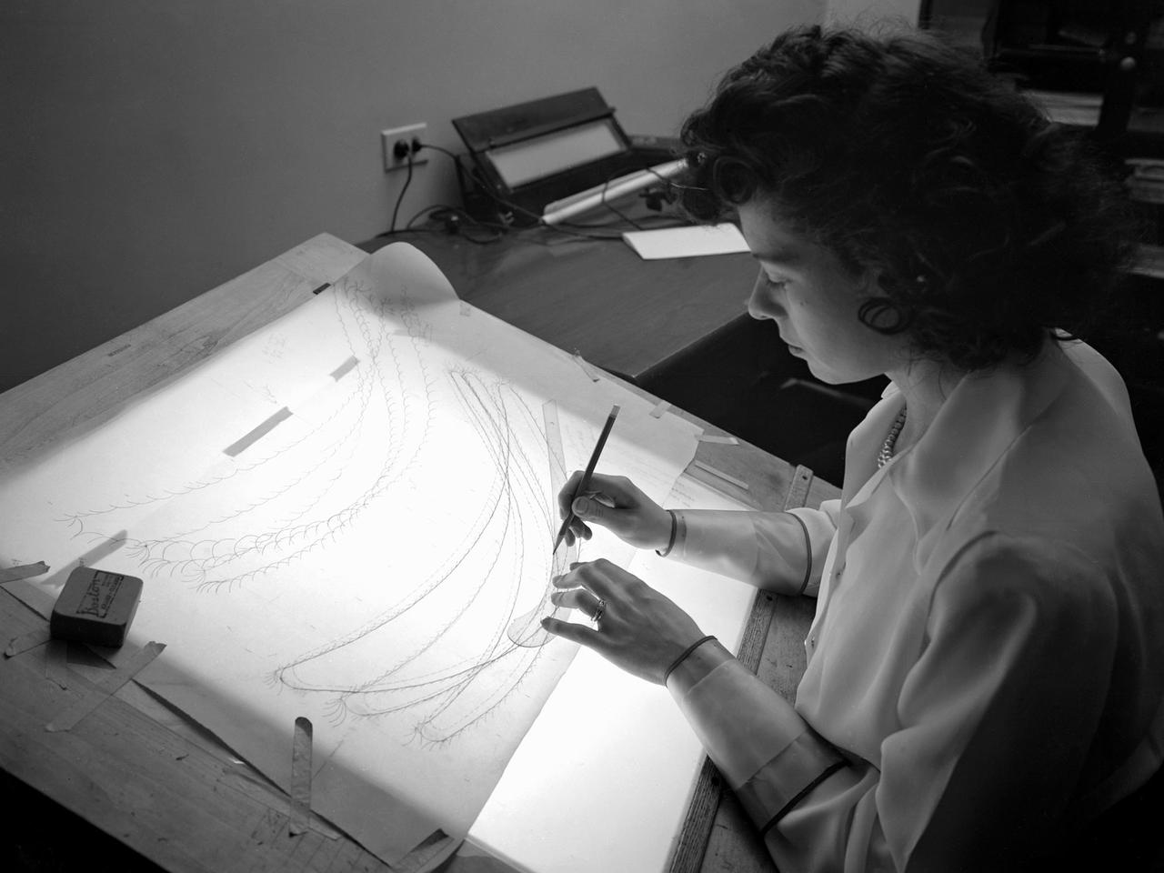
A female computer plotting compressor data in the Engine Research Building at the NACA’s Lewis Flight Propulsion Laboratory. The Computing Section was introduced during World War II to relieve short-handed research engineers of some of the tedious data-taking work. The computers made the initial computations and plotted the data graphically. The researcher then analyzed the data and either summarized the findings in a report or made modifications or ran the test again. With the introduction of mechanical computer systems in the 1950s the female computers learned how to encode the punch cards. As the data processing capabilities increased, fewer female computers were needed. Many left on their own to start families, while others earned mathematical degrees and moved into advanced positions.
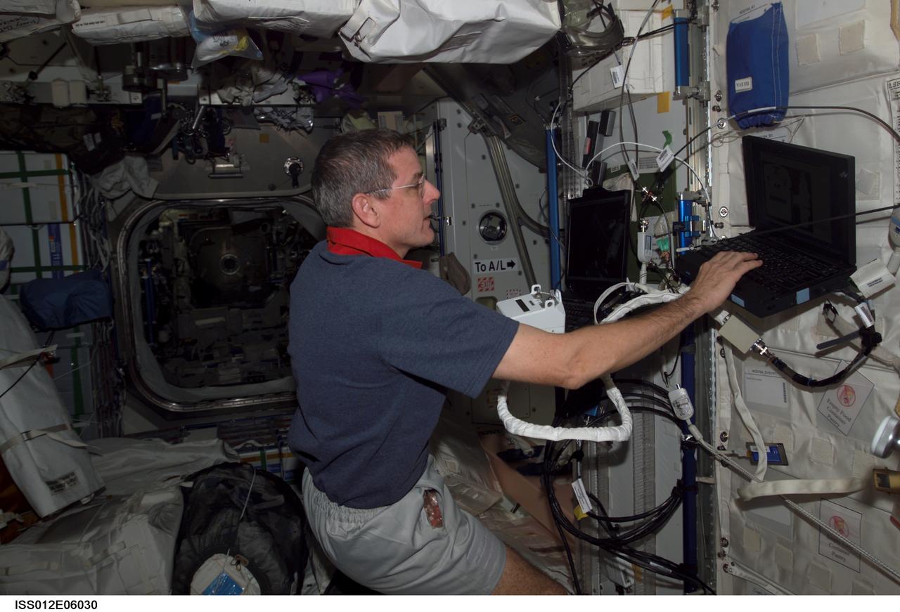
ISS012-E-06030 (21 October 2005) --- Astronaut William S. McArthur Jr., Expedition 12 commander and NASA science officer, holds a Hand Control Module (HCM) while looking at laptop computer graphics during a Simplified Aid for EVA Rescue (SAFER) training session in the Unity node of the international space station.
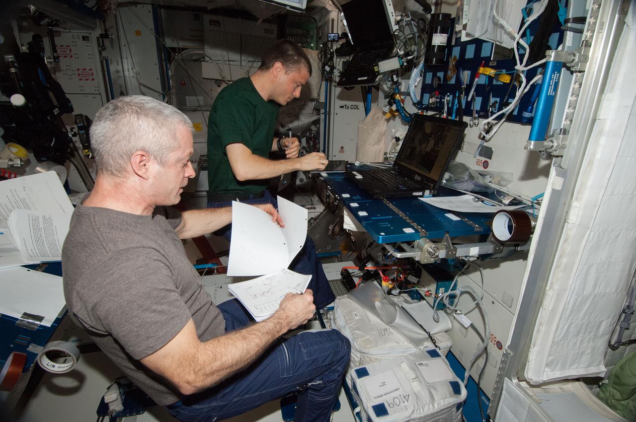
ISS040-E-088730 (4 Aug. 2014) --- In the International Space Station?s Harmony node, NASA astronauts Steve Swanson (foreground), Expedition 40 commander; and Reid Wiseman, flight engineer, perform a portable onboard computer Dynamic Onboard Ubiquitous Graphics (DOUG) software review in preparation for two upcoming U.S. spacewalks.
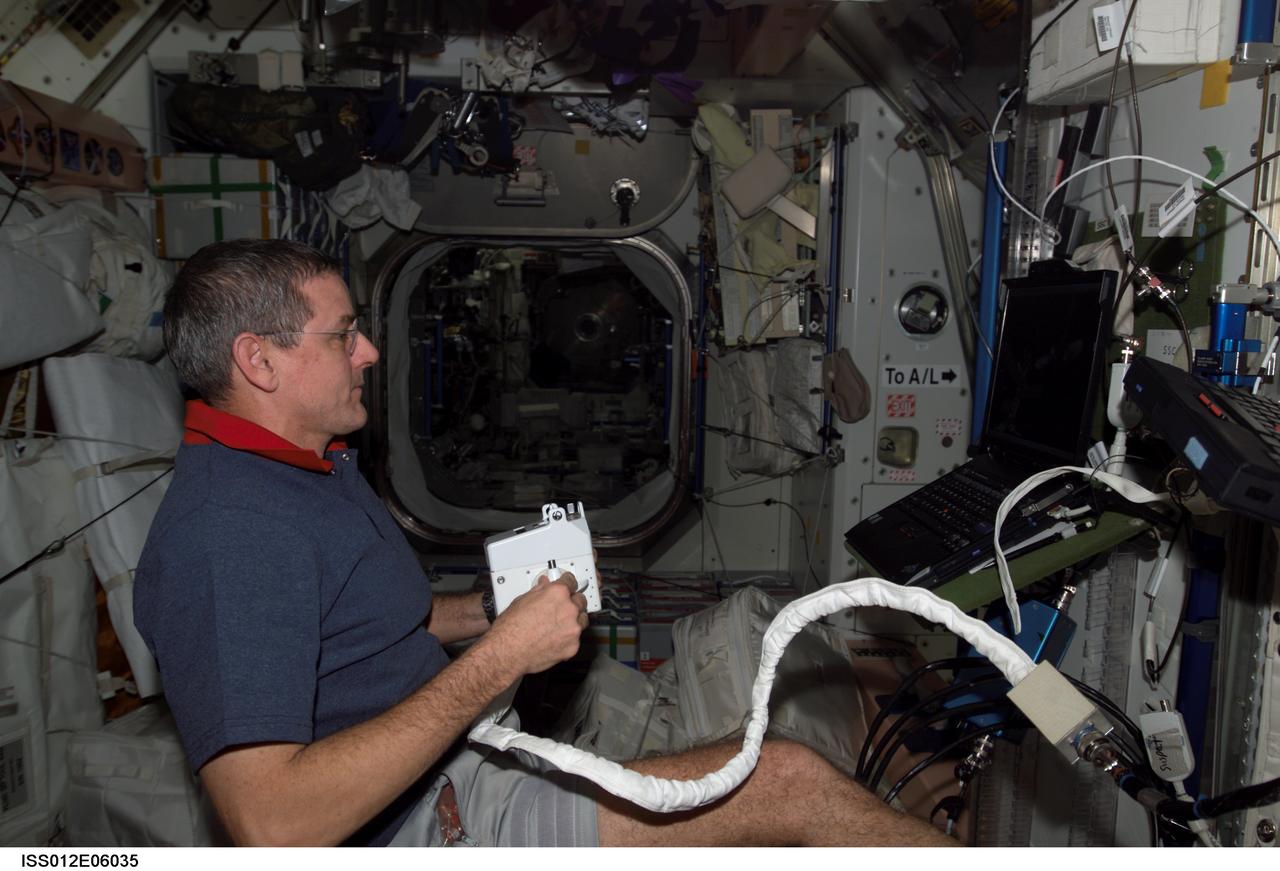
ISS012-E-06035 (21 October 2005) --- Astronaut William S. McArthur Jr., Expedition 12 commander and NASA science officer, holds a Hand Control Module (HCM) while looking at laptop computer graphics during a Simplified Aid for EVA Rescue (SAFER) training session in the Unity node of the international space station.
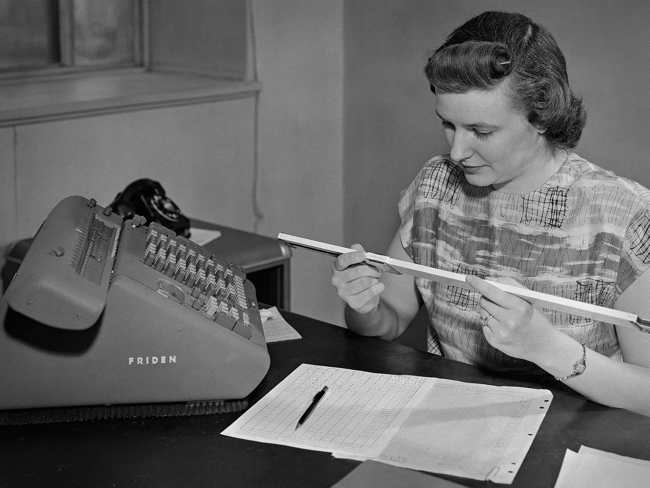
A female computer at the National Advisory Committee for Aeronautics (NACA) Lewis Flight Propulsion Laboratory with a slide rule and Friden adding machine to make computations. The computer staff was introduced during World War II to relieve short-handed research engineers of some of the tedious computational work. The Computing Section was staffed by “computers,” young female employees, who often worked overnight when most of the tests were run. The computers obtained test data from the manometers and other instruments, made the initial computations, and plotted the data graphically. Researchers then analyzed the data and summarized the findings in a report or made modifications and ran the test again. There were over 400 female employees at the laboratory in 1944, including 100 computers. The use of computers was originally planned only for the duration of the war. The system was so successful that it was extended into the 1960s. The computers and analysts were located in the Altitude Wind Tunnel Shop and Office Building office wing during the 1940s and transferred to the new 8- by 6-Foot Supersonic Wind Tunnel in 1948.
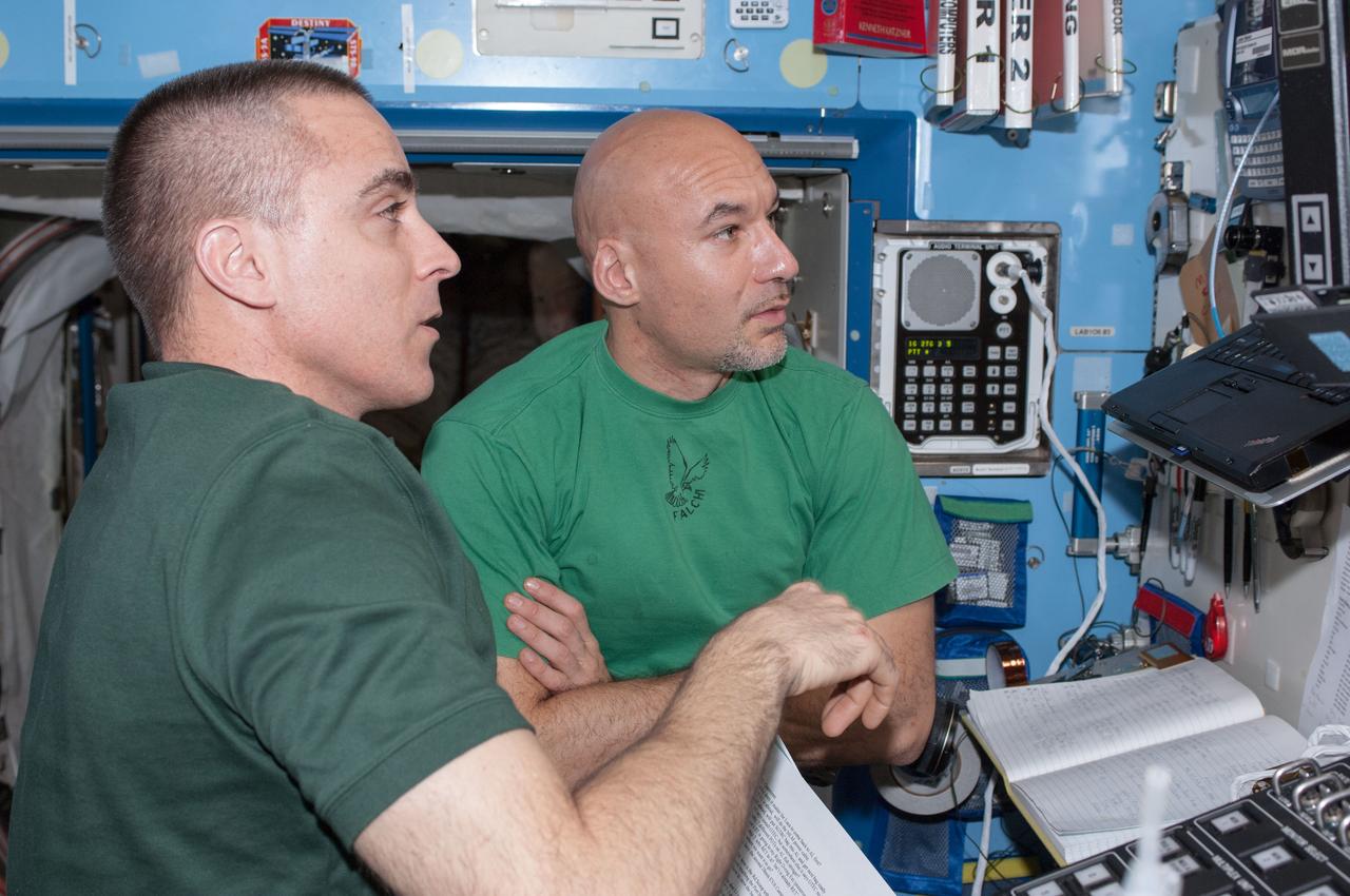
ISS036-E-012130 (25 June 2013) --- NASA astronaut Chris Cassidy (left) and European Space Agency astronaut Luca Parmitano, both Expedition 36 flight engineers, perform a Portable Onboard Computers (POC) Dynamic Onboard Ubiquitous Graphics (DOUG) software review in preparation for spacewalks scheduled for July 9 and July 16.
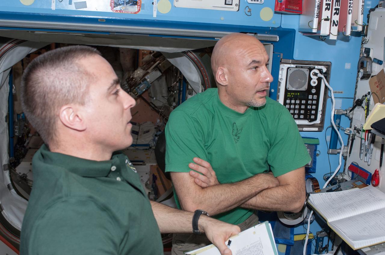
ISS036-E-012131 (25 June 2013) --- NASA astronaut Chris Cassidy (left) and European Space Agency astronaut Luca Parmitano, both Expedition 36 flight engineers, perform a Portable Onboard Computers (POC) Dynamic Onboard Ubiquitous Graphics (DOUG) software review in preparation for spacewalks scheduled for July 9 and July 16.
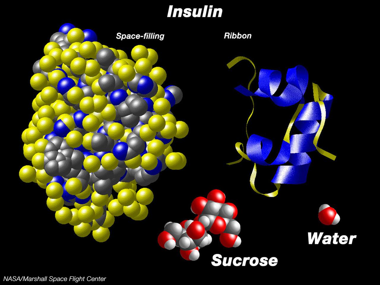
This computer graphic depicts the relative complexity of crystallizing large proteins in order to study their structures through x-ray crystallography. Insulin is a vital protein whose structure has several subtle points that scientists are still trying to determine. Large molecules such as insuline are complex with structures that are comparatively difficult to understand. For comparison, a sugar molecule (which many people have grown as hard crystals in science glass) and a water molecule are shown. These images were produced with the Macmolecule program. Photo credit: NASA/Marshall Space Flight Center (MSFC)
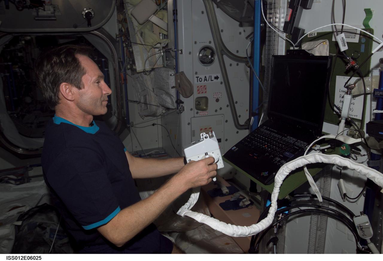
ISS012-E-06025 (21 October 2005) --- Cosmonaut Valery I. Tokarev, Expedition 12 flight engineer representing Russia's Federal Space Agency, holds a Hand Control Module (HCM) while looking at laptop computer graphics during a Simplified Aid for EVA Rescue (SAFER) training session in the Unity node of the international space station.

This graphic shows the computer simulation of a black hole from start to finish. Plasma is falling slowly toward the black hole in a (at the upper left). The plasma has a magnetic field, shown by the white lines. It picks up speed as it falls toward the hole in b (at the upper right), c (lower left) and d (lower right). However, the rotating black hole twists up space itself (and the magnetic field lines) and ejects electromagnetic power along the north and south poles above the black hole. The red and white color shows the immense electromagnetic power output, which eventually will pick up particles and form squirting jets. This simulation was conducted using supercomputers at Japan's National Institute for Fusion Science. http://photojournal.jpl.nasa.gov/catalog/PIA04206
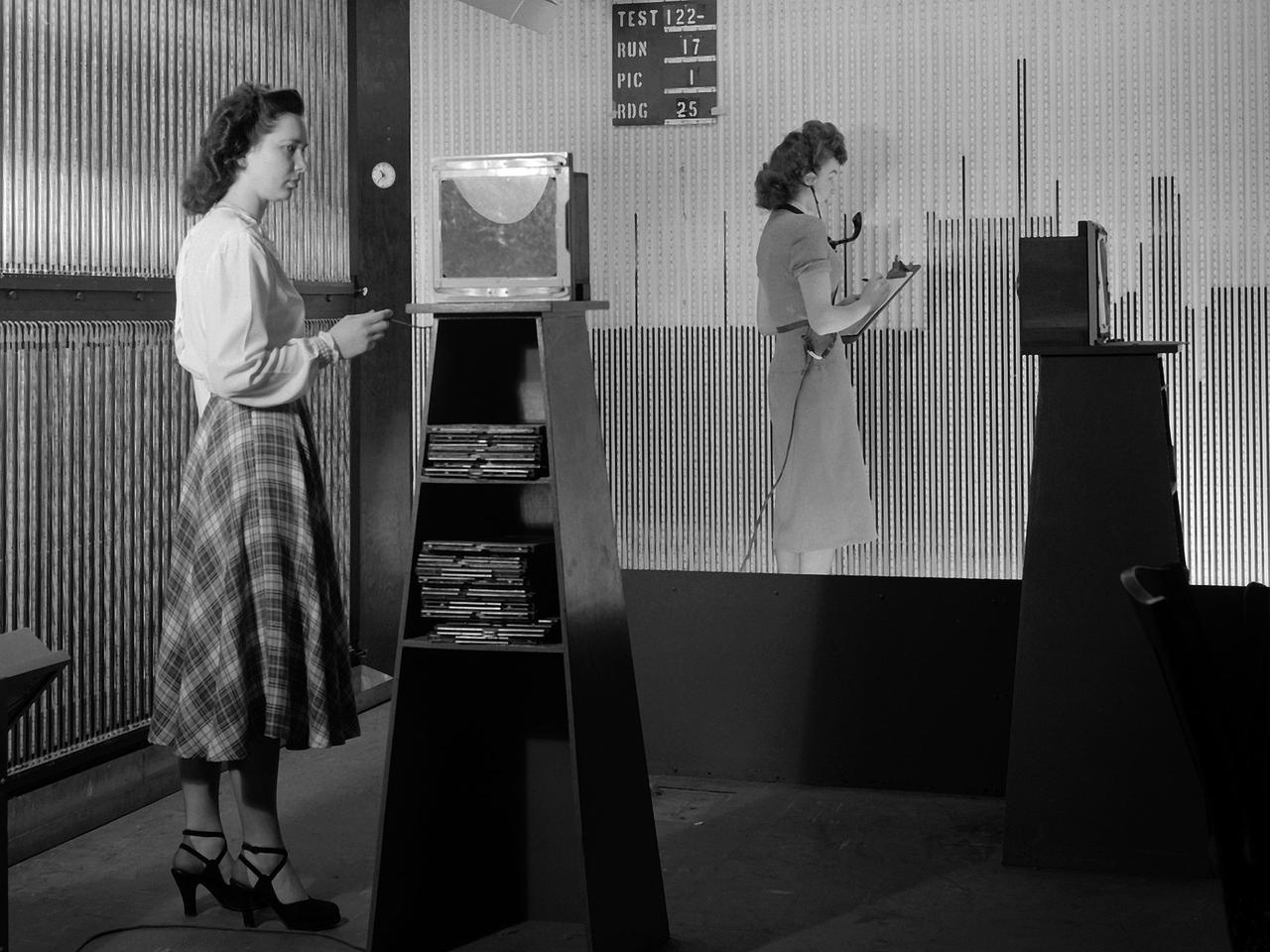
Female computers at the National Advisory Committee for Aeronautics (NACA) Lewis Flight Propulsion Laboratory copy pressure readings from rows of manometers below the 18- by 18-inch Supersonic Wind Tunnel. The computers obtained test data from the manometers and other instruments, made the initial computations, and plotted the information graphically. Based on these computations, the researchers planned their next test or summarized their findings in a report. Manometers were mercury-filled glass tubes that were used to indicate different pressure levels from inside the test facility or from the test article. Manometers look and function very similarly to thermometers. Dozens of pressure sensing instruments were installed for each test. Each was connected to a manometer tube located inside the control room. The mercury inside the manometer rose and fell with the pressure levels. The dark mercury can be seen in this photograph at different levels within the tubes. Since this activity was dynamic, it was necessary to note the levels at given points during the test. This was done using both computer notations and photography.
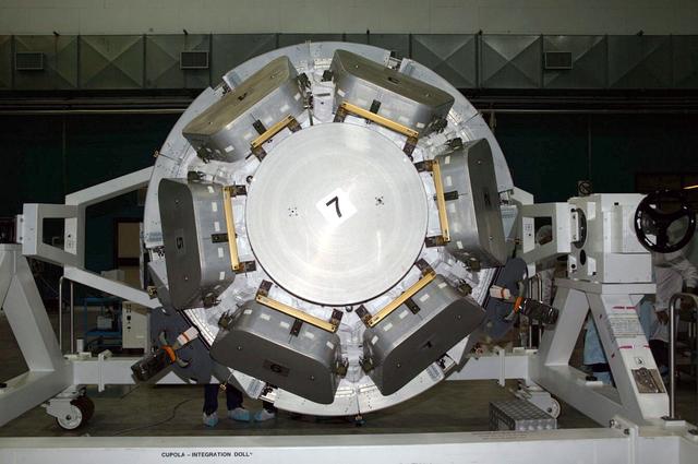
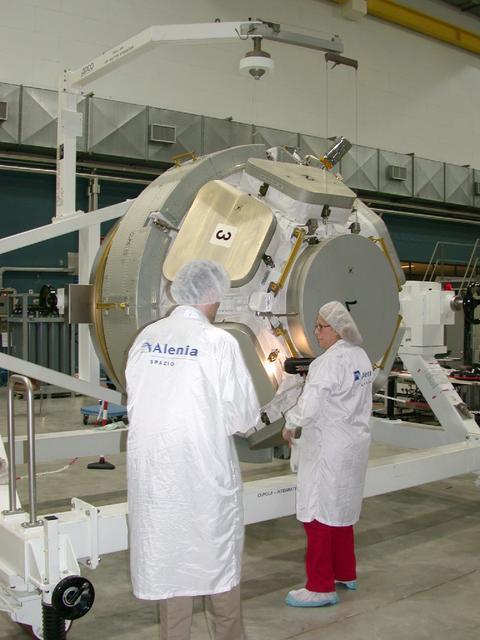
JSC2004-E-44649 (September 2004) --- Engineers and technicians (partially visible in right background) check the International Space Station's Cupola in the Alenia Spazio clean room in Turin, Italy. Personnel are preparing the hardware for shipment to NASA's launch facility at Cape Kennedy, Florida. From inside the Cupola, a dome-shaped module with seven windows, astronauts have a panoramic view for observing operations on the outside of the orbiting complex. The Cupola module provides external observation capabilities during spacewalks, docking operations, hardware surveys and for Earth and celestial studies. It also serves as the primary location for executing robot arm operations of Canadarm2. Until the Cupola is installed, crews have been using a robotic control computer station located in the Destiny Laboratory to operate the arm. The Cupola’s windows enhance the robotic arm operator's situational awareness, supplementing camera and graphic views provided by the computer workstation. Photo Credit: Alenia Spazio

JSC2004-E-42739 (August 2004) --- A low angle view shows the interior of the International Space Station's Cupola in the Alenia Spazio clean room in Turin, Italy. Personnel are preparing the hardware for shipment to NASA's launch facility at Cape Kennedy, Florida. From inside the Cupola, a dome-shaped module with seven windows, astronauts have a panoramic view for observing operations on the outside of the orbiting complex. The Cupola module provides external observation capabilities during spacewalks, docking operations, hardware surveys and for Earth and celestial studies. It also serves as the primary location for executing robot arm operations of Canadarm2. Until the Cupola is installed, crews have been using a robotic control computer station located in the Destiny Laboratory to operate the arm. The Cupola’s windows enhance the robotic arm operator's situational awareness, supplementing camera and graphic views provided by the computer workstation. Photo Credit: Alenia Spazio
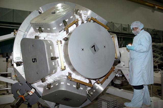
JSC2004-E-44648 (September 2004) --- A technician checks the International Space Station's Cupola in the Alenia Spazio clean room in Turin, Italy. Personnel are preparing the hardware for shipment to NASA's launch facility at Cape Kennedy, Florida. From inside the Cupola, a dome-shaped module with seven windows, astronauts have a panoramic view for observing operations on the outside of the orbiting complex. The Cupola module provides external observation capabilities during spacewalks, docking operations, hardware surveys and for Earth and celestial studies. It also serves as the primary location for executing robot arm operations of Canadarm2. Until the Cupola is installed, crews have been using a robotic control computer station located in the Destiny Laboratory to operate the arm. The Cupola’s windows enhance the robotic arm operator's situational awareness, supplementing camera and graphic views provided by the computer workstation. Photo Credit: Alenia Spazio
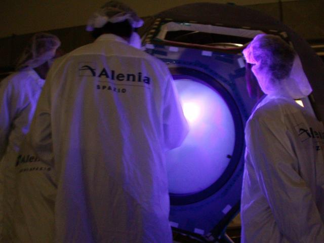
JSC2004-E-42740 (August 2004) --- Engineers and technicians check the International Space Station's Cupola in the Alenia Spazio clean room in Turin, Italy. Personnel are preparing the hardware for shipment to NASA's launch facility at Cape Kennedy, Florida. From inside the Cupola, a dome-shaped module with seven windows, astronauts have a panoramic view for observing operations on the outside of the orbiting complex. The Cupola module provides external observation capabilities during spacewalks, docking operations, hardware surveys and for Earth and celestial studies. It also serves as the primary location for executing robot arm operations of Canadarm2. Until the Cupola is installed, crews have been using a robotic control computer station located in the Destiny Laboratory to operate the arm. The Cupola’s windows enhance the robotic arm operator's situational awareness, supplementing camera and graphic views provided by the computer workstation. Photo Credit: Alenia Spazio
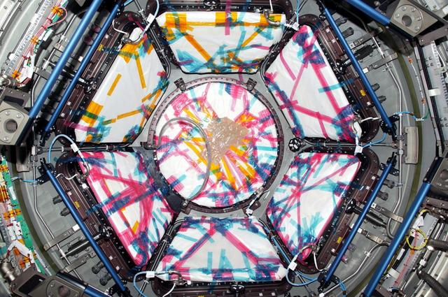
JSC2004-E-44650 (September 2004) --- A crewmember-eye view of the International Space Station's Cupola in the Alenia Spazio clean room in Turin, Italy. Personnel are preparing the hardware for shipment to NASA's launch facility at Cape Kennedy, Florida. From inside the Cupola, a dome-shaped module with seven windows (seen here under a protective cover), astronauts have a panoramic view for observing operations on the outside of the orbiting complex. The Cupola module provides external observation capabilities during spacewalks, docking operations, hardware surveys and for Earth and celestial studies. It also serves as the primary location for executing robot arm operations of Canadarm2. Until the Cupola is installed, crews have been using a robotic control computer station located in the Destiny Laboratory to operate the arm. The Cupola’s windows enhance the robotic arm operator's situational awareness, supplementing camera and graphic views provided by the computer workstation. Photo Credit: Alenia Spazio
JSC2004-E-42742 (August 2004) --- Engineers and technicians check the International Space Station's Cupola in the Alenia Spazio clean room in Turin, Italy. Personnel are preparing the hardware for shipment to NASA's launch facility at Cape Kennedy, Florida. From inside the Cupola, a dome-shaped module with seven windows, astronauts have a panoramic view for observing operations on the outside of the orbiting complex. The Cupola module provides external observation capabilities during spacewalks, docking operations, hardware surveys and for Earth and celestial studies. It also serves as the primary location for executing robot arm operations of Canadarm2. Until the Cupola is installed, crews have been using a robotic control computer station located in the Destiny Laboratory to operate the arm. The Cupola’s windows enhance the robotic arm operator's situational awareness, supplementing camera and graphic views provided by the computer workstation. Photo Credit: Alenia Spazio
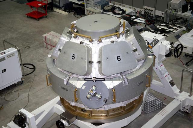
JSC2004-E-44647 (September 2004) --- A slightly high-angle view of the International Space Station's Cupola in the Alenia Spazio clean room in Turin, Italy. Personnel are preparing the hardware for shipment to NASA's launch facility at Cape Kennedy, Florida. From inside the Cupola, a dome-shaped module with seven windows, astronauts have a panoramic view for observing operations on the outside of the orbiting complex. The Cupola module provides external observation capabilities during spacewalks, docking operations, hardware surveys and for Earth and celestial studies. It also serves as the primary location for executing robot arm operations of Canadarm2. Until the Cupola is installed, crews have been using a robotic control computer station located in the Destiny Laboratory to operate the arm. The Cupola’s windows enhance the robotic arm operator's situational awareness, supplementing camera and graphic views provided by the computer workstation. Photo Credit: Alenia Spazio
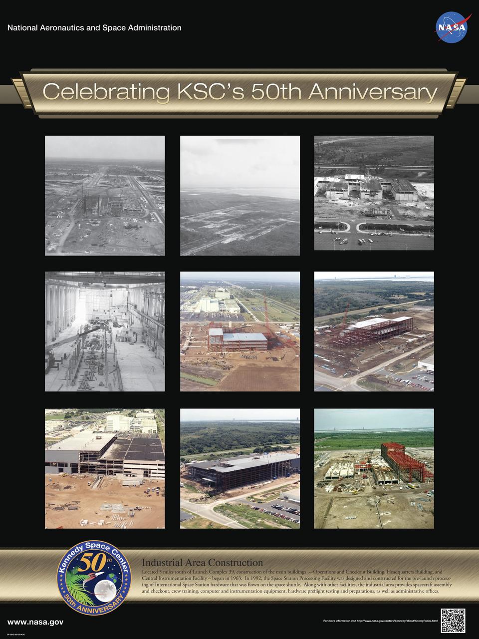
Industrial Area Construction: Located 5 miles south of Launch Complex 39, construction of the main buildings -- Operations and Checkout Building, Headquarters Building, and Central Instrumentation Facility – began in 1963. In 1992, the Space Station Processing Facility was designed and constructed for the pre-launch processing of International Space Station hardware that was flown on the space shuttle. Along with other facilities, the industrial area provides spacecraft assembly and checkout, crew training, computer and instrumentation equipment, hardware preflight testing and preparations, as well as administrative offices. Poster designed by Kennedy Space Center Graphics Department/Greg Lee. Credit: NASA
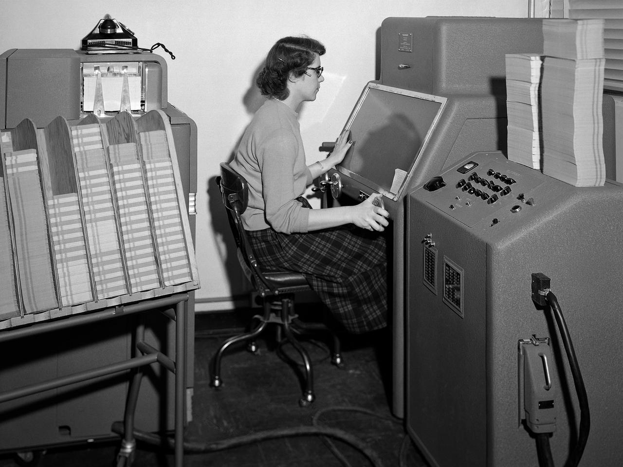
A staff member from the Computing Section at the National Advisory Committee for Aeronautics (NACA) Lewis Flight Propulsion Laboratory operates an International Business Machines (IBM) telereader at the 8- by 6-Foot Supersonic Wind Tunnel. The telereader was used to measure recorded data from motion picture film or oscillographs. The machine could perform 50 measurements per minute. The component to her right is a telerecordex that was used convert the telereader measurements into decimal form and record the data on computer punch cards. During test runs in the 8- by 6-foot tunnel, or the other large test facilities, pressure sensors on the test article were connected to mercury-filled manometer tubes located below the test section. The mercury would rise or fall in relation to the pressure fluctuations in the test section. Initially, female staff members, known as “computers,” transcribed all the measurements by hand. The process became automated with the introduction of the telereader and other data reduction equipment in the early 1950s. The Computer Section staff members were still needed to operate the machines. The Computing Section was introduced during World War II to relieve short-handed research engineers of some of the tedious work. The computers made the initial computations and plotted the data graphically. The researcher then analyzed the data and either summarized the findings in a report or made modifications or ran the test again. The computers and analysts were located in the Altitude Wind Tunnel Shop and Office Building office wing during the 1940s. They were transferred to the new facility when the 8- by 6-Foot tunnel began operations in 1948.
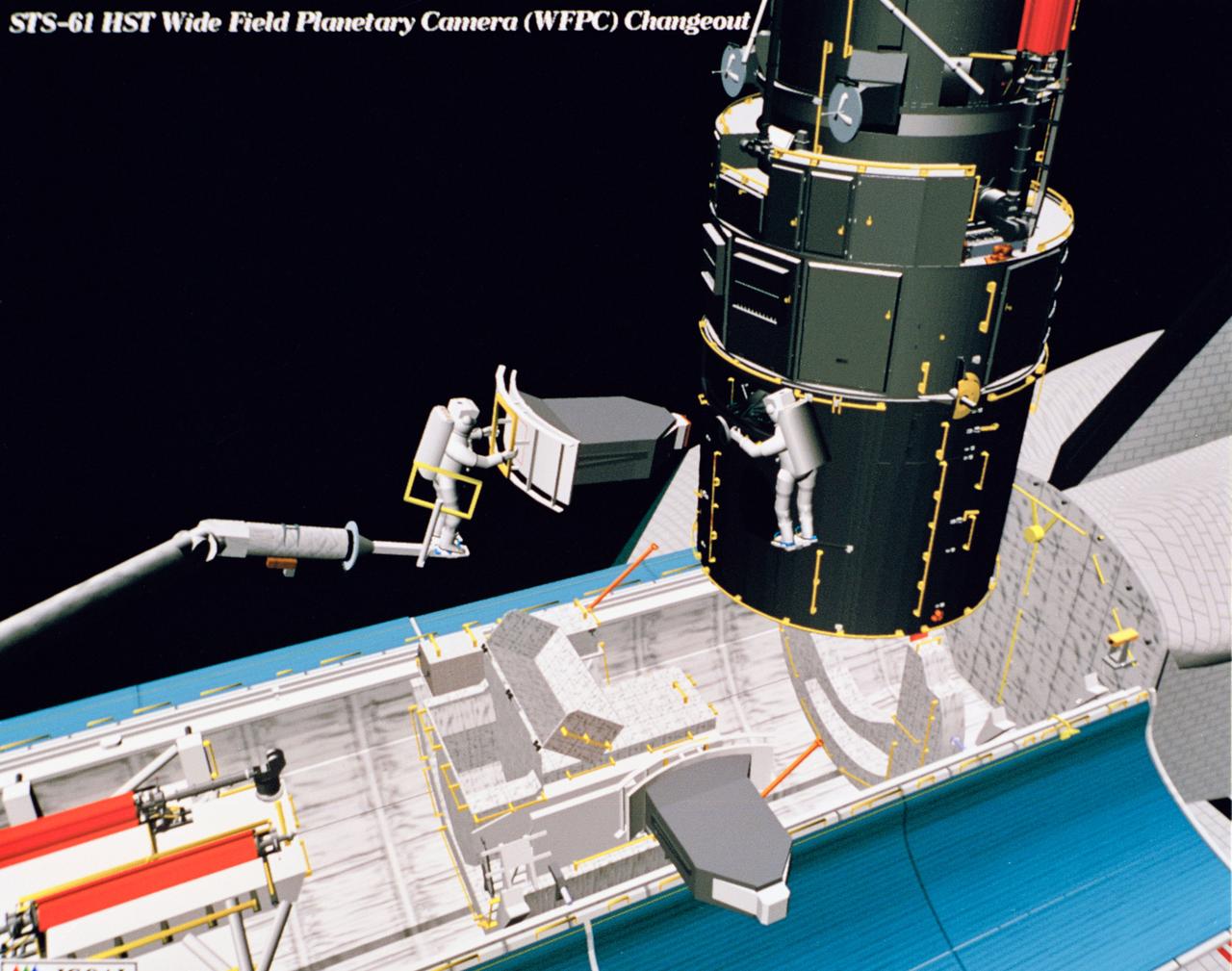
Computer generated scenes depicting the Hubble Space Telescope capture and a sequence of planned events on the planned extravehicular activity (EVA). Scenes include the Remote Manipulator System (RMS) arm assisting two astronauts changing out the Wide Field/Planetary Camera (WF/PC) (48699); RMS arm assisting in the temporary mating of the orbiting telescope to the flight support system in Endeavour's cargo bay (48700); Endeavour's RMS arm assisting in the "capture" of the orbiting telescope (48701); Two astronauts changing out the telescope's coprocessor (48702); RMS arm assistign two astronauts replacing one of the telescope's electronic control units (48703); RMS assisting two astronauts replacing the fuse plugs on the telescope's Power Distribution Unit (PDU) (48704); The telescope's High Resolution Spectrograph (HRS) kit is depicted in this scene (48705); Two astronauts during the removal of the high speed photometer and the installation of the COSTAR instrument (48706); Two astronauts, standing on the RMS, during installation of one of the Magnetic Sensing System (MSS) (48707); High angle view of the orbiting Space Shuttle Endeavour with its cargo bay doors open, revealing the bay's pre-capture configuration. Seen are, from the left, the Solar Array Carrier, the ORU Carrier and the flight support system (48708); Two astronauts performing the replacement of HST's Rate Sensor Units (RSU) (48709); The RMS arm assisting two astronauts with the replacement of the telescope's solar array panels (48710); Two astronauts replacing the telescope's Solar Array Drive Electronics (SADE) (48711).
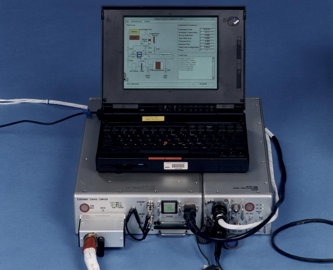
Laptop computer sits atop the Experiment Control Computer for a NASA Bioreactor. The flight crew can change operating conditions in the Bioreactor by using the graphical interface on the laptop. The NASA Bioreactor provides a low turbulence culture environment which promotes the formation of large, three-dimensional cell clusters. The Bioreactor is rotated to provide gentle mixing of fresh and spent nutrient without inducing shear forces that would damage the cells. Due to their high level of cellular organization and specialization, samples constructed in the bioreactor more closely resemble the original tumor or tissue found in the body. The work is sponsored by NASA's Office of Biological and Physical Research. The bioreactor is managed by the Biotechnology Cell Science Program at NASA's Johnson Space Center (JSC). NASA-sponsored bioreactor research has been instrumental in helping scientists to better understand normal and cancerous tissue development. In cooperation with the medical community, the bioreactor design is being used to prepare better models of human colon, prostate, breast and ovarian tumors. Cartilage, bone marrow, heart muscle, skeletal muscle, pancreatic islet cells, liver and kidney are just a few of the normal tissues being cultured in rotating bioreactors by investigators.
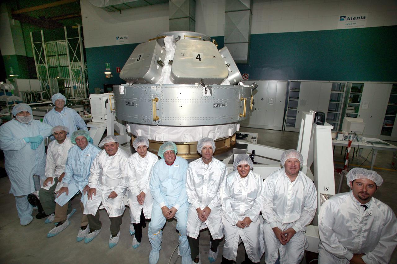
JSC2004-E-44646 (September 2004) --- Engineers and technicians who have been working hard on the International Space Station's Cupola are pictured with the hardware in the Alenia Spazio clean room in Turin, Italy. The personnel have been preparing the hardware for shipment to NASA's launch facility at Cape Kennedy, Florida. From inside the Cupola, a dome-shaped module with seven windows, astronauts have a panoramic view for observing operations on the outside of the orbiting complex. The Cupola module provides external observation capabilities during spacewalks, docking operations, hardware surveys and for Earth and celestial studies. It also serves as the primary location for executing robot arm operations of Canadarm2. Until the Cupola is installed, crews have been using a robotic control computer station located in the Destiny Laboratory to operate the arm. The Cupola’s windows enhance the robotic arm operator's situational awareness, supplementing camera and graphic views provided by the computer workstation. Photo Credit: Alenia Spazio

JSC2004-E-44645 (September 2004) --- This view of the International Space Station's Cupola features the portion where the grapple fixture is located. The Canadian-built remote manipulator system on either the Station or Space Shuttle will be able to grasp the Cupola with this fixture. This is one of a series of photos showing completed work on the hardware at the Alenia Spazio clean room in Turin, Italy. The personnel have been preparing the hardware for shipment to NASA's launch facility at Cape Kennedy, Florida. From inside the Cupola, a dome-shaped module with seven windows, astronauts have a panoramic view for observing operations on the outside of the orbiting complex. The Cupola module provides external observation capabilities during spacewalks, docking operations, hardware surveys and for Earth and celestial studies. It also serves as the primary location for executing robot arm operations of Canadarm2. Until the Cupola is installed, crews have been using a robotic control computer station located in the Destiny Laboratory to operate the arm. The Cupola’s windows enhance the robotic arm operator's situational awareness, supplementing camera and graphic views provided by the computer workstation. Photo Credit: Alenia Spazio
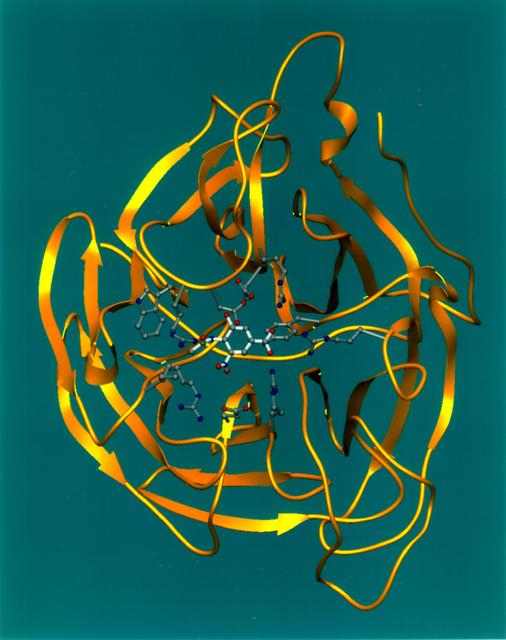
Ribbons is a program developed at UAB used worldwide to graphically depict complicated protein structures in a simplified format. The program uses sophisticated computer systems to understand the implications of protein structures. The Influenza virus remains a major causative agent for a large number of deaths among the elderly and young children and huge economic losses due to illness. Finding a cure will have a general impact both on the basic research of viral pathologists of fast evolving infectious agents and clinical treatment of influenza virus infection. The reproduction process of all strains of influenza are dependent on the same enzyme neuraminidase. Shown here is a segmented representation of the neuraminidase inhibitor compound sitting inside a cave-like contour of the neuraminidase enzyme surface. This cave-like formation present in every neuraminidase enzyme is the active site crucial to the flu's ability to infect. The space-grown crystals of neuraminidase have provided significant new details about the three-dimensional characteristics of this active site thus allowing researchers to design drugs that fit tighter into the site. Principal Investigator: Dr. Larry DeLucas
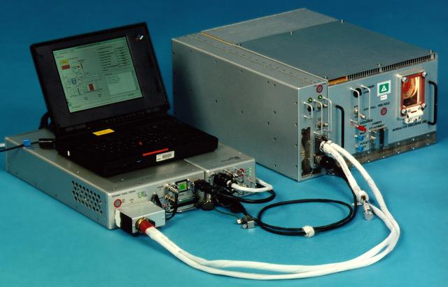
Bioreactor Demonstration System (BDS) comprises an electronics module, a gas supply module, and the incubator module housing the rotating wall vessel and its support systems. Nutrient media are pumped through an oxygenator and the culture vessel. The shell rotates at 0.5 rpm while the irner filter typically rotates at 11.5 rpm to produce a gentle flow that ensures removal of waste products as fresh media are infused. Periodically, some spent media are pumped into a waste bag and replaced by fresh media. When the waste bag is filled, an astronaut drains the waste bag and refills the supply bag through ports on the face of the incubator. Pinch valves and a perfusion pump ensure that no media are exposed to moving parts. An Experiment Control Computer controls the Bioreactor, records conditions, and alerts the crew when problems occur. The crew operates the system through a laptop computer displaying graphics designed for easy crew training and operation. The work is sponsored by NASA's Office of Biological and Physical Research. The bioreactor is managed by the Biotechnology Cell Science Program at NASA's Johnson Space Center (JSC). NASA-sponsored bioreactor research has been instrumental in helping scientists to better understand normal and cancerous tissue development. In cooperation with the medical community, the bioreactor design is being used to prepare better models of human colon, prostate, breast and ovarian tumors. Cartilage, bone marrow, heart muscle, skeletal muscle, pancreatic islet cells, liver and kidney are just a few of the normal tissues being cultured in rotating bioreactors by investigators. See No. 0101824 for a version with labels, and No. 0103180 for an operational schematic.
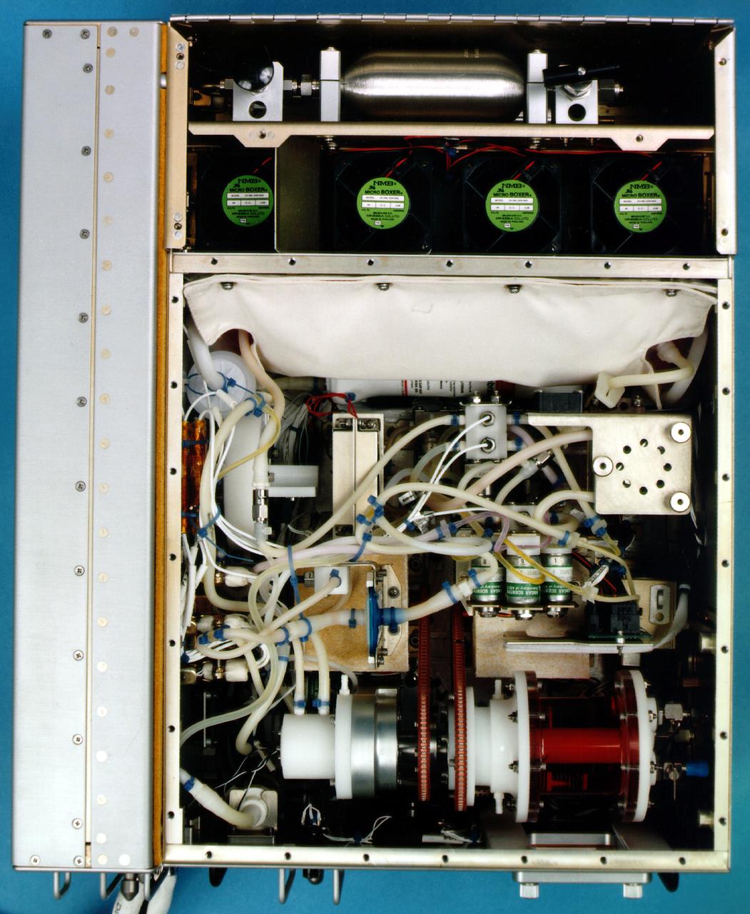
Bioreactor Demonstration System (BDS) comprises an electronics module, a gas supply module, and the incubator module housing the rotating wall vessel and its support systems. Nutrient media are pumped through an oxygenator and the culture vessel. The shell rotates at 0.5 rpm while the irner filter typically rotates at 11.5 rpm to produce a gentle flow that ensures removal of waste products as fresh media are infused. Periodically, some spent media are pumped into a waste bag and replaced by fresh media. When the waste bag is filled, an astronaut drains the waste bag and refills the supply bag through ports on the face of the incubator. Pinch valves and a perfusion pump ensure that no media are exposed to moving parts. An Experiment Control Computer controls the Bioreactor, records conditions, and alerts the crew when problems occur. The crew operates the system through a laptop computer displaying graphics designed for easy crew training and operation. The work is sponsored by NASA's Office of Biological and Physical Research. The bioreactor is managed by the Biotechnology Cell Science Program at NASA's Johnson Space Center (JSC). NASA-sponsored bioreactor research has been instrumental in helping scientists to better understand normal and cancerous tissue development. In cooperation with the medical community, the bioreactor design is being used to prepare better models of human colon, prostate, breast and ovarian tumors. Cartilage, bone marrow, heart muscle, skeletal muscle, pancreatic islet cells, liver and kidney are just a few of the normal tissues being cultured in rotating bioreactors by investigators. See No. 0101825 for a version with major elements labeled, and No. 0103180 for an operational schematic. 0101816
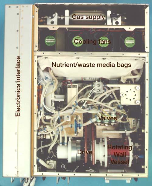
Bioreactor Demonstration System (BDS) comprises an electronics module, a gas supply module, and the incubator module housing the rotating wall vessel and its support systems. Nutrient media are pumped through an oxygenator and the culture vessel. The shell rotates at 0.5 rpm while the irner filter typically rotates at 11.5 rpm to produce a gentle flow that ensures removal of waste products as fresh media are infused. Periodically, some spent media are pumped into a waste bag and replaced by fresh media. When the waste bag is filled, an astronaut drains the waste bag and refills the supply bag through ports on the face of the incubator. Pinch valves and a perfusion pump ensure that no media are exposed to moving parts. An Experiment Control Computer controls the Bioreactor, records conditions, and alerts the crew when problems occur. The crew operates the system through a laptop computer displaying graphics designed for easy crew training and operation. The work is sponsored by NASA's Office of Biological and Physical Research. The bioreactor is managed by the Biotechnology Cell Science Program at NASA's Johnson Space Center (JSC). NASA-sponsored bioreactor research has been instrumental in helping scientists to better understand normal and cancerous tissue development. In cooperation with the medical community, the bioreactor design is being used to prepare better models of human colon, prostate, breast and ovarian tumors. Cartilage, bone marrow, heart muscle, skeletal muscle, pancreatic islet cells, liver and kidney are just a few of the normal tissues being cultured in rotating bioreactors by investigators. See No. 0101816 for a version without labels, and No. 0103180 for an operational schematic.
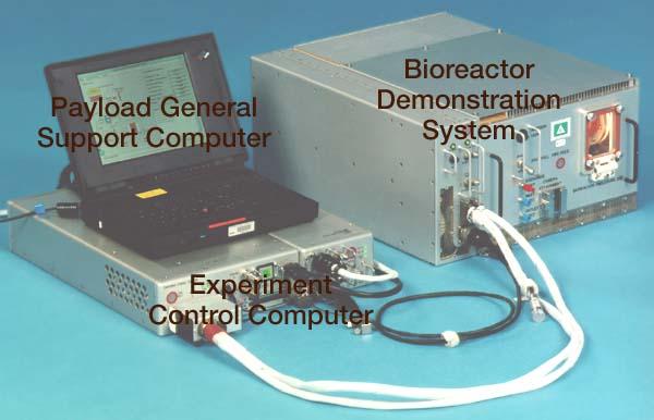
Bioreactor Demonstration System (BDS) comprises an electronics module, a gas supply module, and the incubator module housing the rotating wall vessel and its support systems. Nutrient media are pumped through an oxygenator and the culture vessel. The shell rotates at 0.5 rpm while the irner filter typically rotates at 11.5 rpm to produce a gentle flow that ensures removal of waste products as fresh media are infused. Periodically, some spent media are pumped into a waste bag and replaced by fresh media. When the waste bag is filled, an astronaut drains the waste bag and refills the supply bag through ports on the face of the incubator. Pinch valves and a perfusion pump ensure that no media are exposed to moving parts. An Experiment Control Computer controls the Bioreactor, records conditions, and alerts the crew when problems occur. The crew operates the system through a laptop computer displaying graphics designed for easy crew training and operation. The work is sponsored by NASA's Office of Biological and Physical Research. The bioreactor is managed by the Biotechnology Cell Science Program at NASA's Johnson Space Center (JSC). NASA-sponsored bioreactor research has been instrumental in helping scientists to better understand normal and cancerous tissue development. In cooperation with the medical community, the bioreactor design is being used to prepare better models of human colon, prostate, breast and ovarian tumors. Cartilage, bone marrow, heart muscle, skeletal muscle, pancreatic islet cells, liver and kidney are just a few of the normal tissues being cultured in rotating bioreactors by investigators. See No. 0101823 for a version without labels, and No. 0103180 for an operational schematic.
jsc2022e062020 (6/30/2022) --- Space Health will create a digital twin of the astronaut from the data collected by the Bio-Monitor and demonstrate how this could be used for autonomous health monitoring on future space missions. (Image courtesy of CSA)

The Roman Coronagraph Instrument on NASA's upcoming Nancy Grace Roman Space Telescope will test new tools that block starlight, revealing planets hidden by the glare of their parent stars. This graphic shows a test of what engineers call "digging the dark hole." The image shows three computer readouts of real data from the coronagraph's camera. Engineers used lasers and special optics to replicate the light from a star as it would look when observed by the Roman telescope. The image at left shows the amount of starlight that leaks into the coronagraph's field of view when only fixed components called masks are used to block the star at the center of the circle. Using moveable components such as deformable mirrors, the coronagraph can remove more and more of this starlight. The middle and right images show the progression of this process, where red indicates less starlight, and black indicates most or all starlight has been removed. The deformable mirrors are each only 2 inches (5 centimeters) in diameter and backed by more than 2,000 tiny pistons that move up and down. The pistons work together to change the shape of the mirrors to compensate for the unwanted stray light that spills around the edges of the masks. Though they are too small to affect Roman's other highly precise measurements, the imperfections can send stray starlight into the dark hole. In space, this technique will enable astronomers to observe light directly from planets around other stars, or exoplanets. Once demonstrated on Roman, similar technologies on a future mission could enable astronomers to use that light to identify chemicals in an exoplanet's atmosphere, potentially indicating the presence of life. https://photojournal.jpl.nasa.gov/catalog/PIA26279