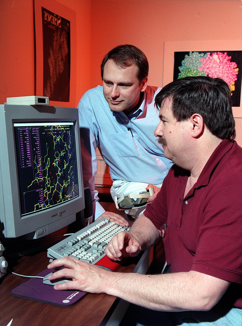
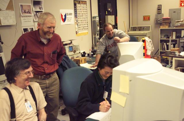
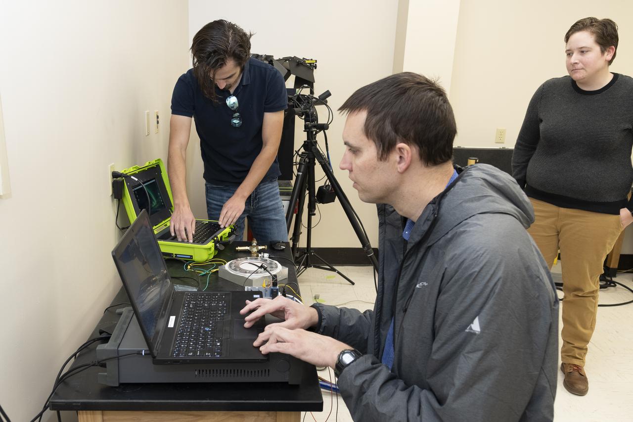
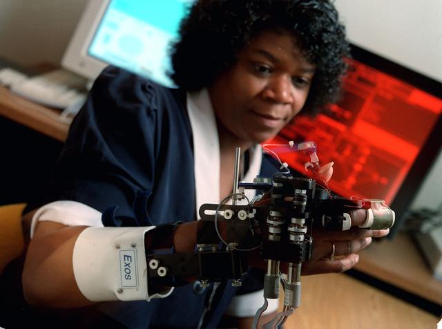
Dr. Marc Pusey (seated) and Dr. Craig Kundrot use computers to analyze x-ray maps and generate three-dimensional models of protein structures. With this information, scientists at Marshall Space Flight Center can learn how proteins are made and how they work. The computer screen depicts a proten structure as a ball-and-stick model. Other models depict the actual volume occupied by the atoms, or the ribbon-like structures that are crucial to a protein's function.
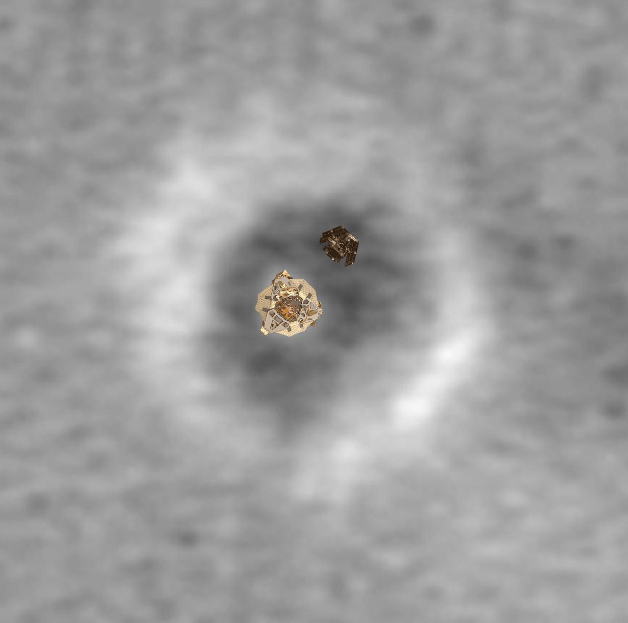
Top View of a Computer Graphic Model of the Opportunity Lander and Rover
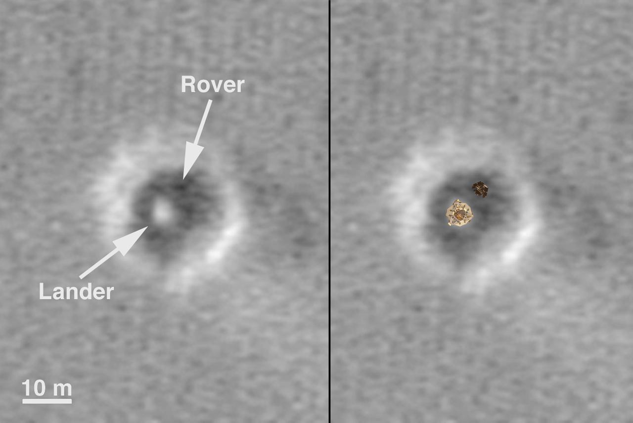
Comparison of a Computer Graphic Model of the Opportunity Lander and Rover with MOC Orbital Image

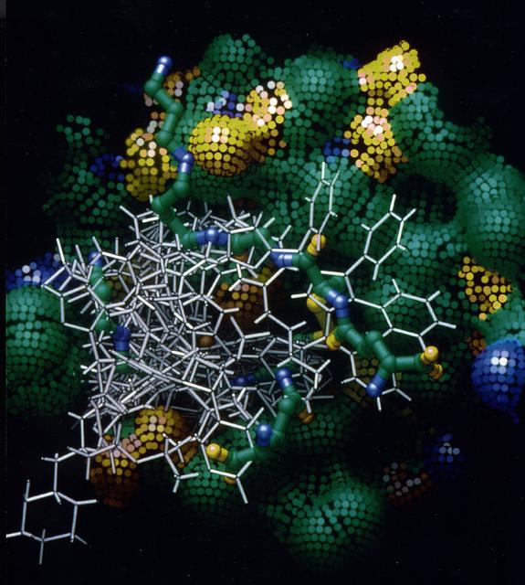
Purine Nucleoside Phosphorylase (PNP) is an important target enzyme for the design of anti-cancer and immunosuppressive drugs. Bacterial PNP, which is slightly different from the human enzyme, is used to synthesize chemotherapuautic agents. Knowledge of the three-dimensional structure of the bacterial PNP molecule is useful in efforts to engineer different types of PNP enzymes, that can be used to produce new chemotherapeutic agents. This picture shows a computer model of bacterial PNP, which looks a lot like a display of colorful ribbons. Principal Investigator was Charles Bugg.
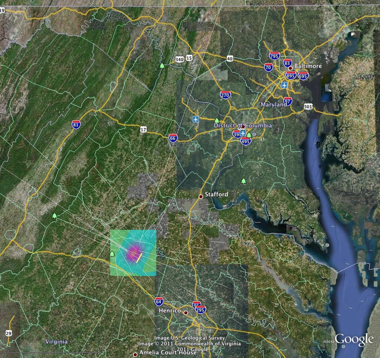
A magnitude 5.8 earthquake in Mineral, Va. was widely felt up and down the East Coast of the United States. This computer model is a QuakeSim model image overlaid on a Google Earth image.
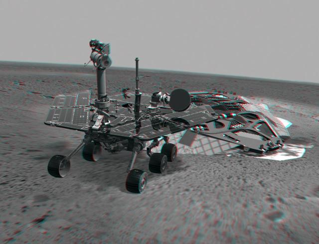
This 3-D image combines computer-generated models of NASA Mars Exploration Rover Spirit and its lander with real surface data from the rover panoramic camera. 3D glasses are necessary to view this image.
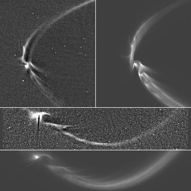
This collage of NASA Cassini spacecraft images and computer simulations shows how long, sinuous features from Enceladus can be modeled by tracing the trajectories of tiny, icy grains ejected from the moon south polar geysers.
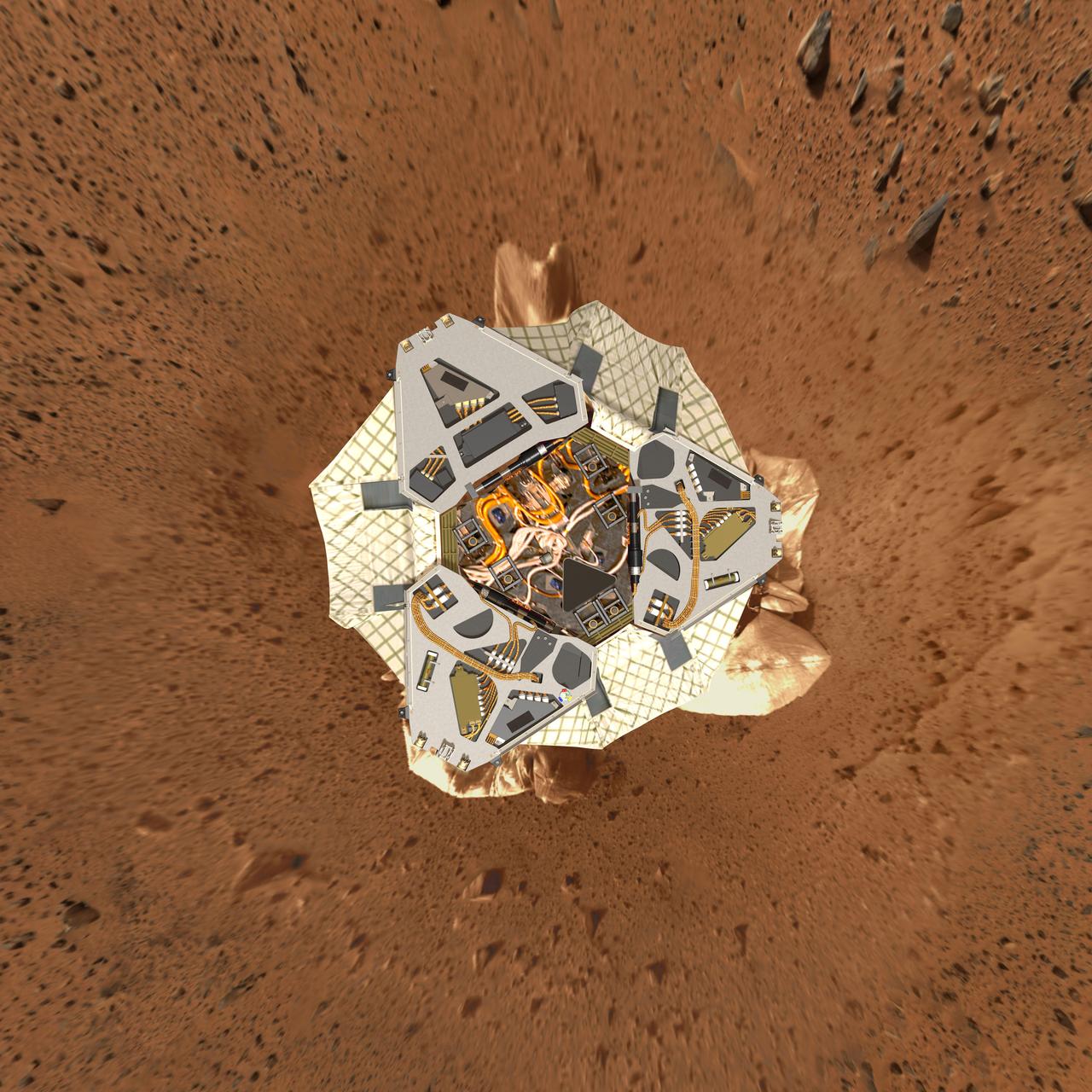
This high-resolution image shows a computer-generated model of Spirit lander at Gusev Crater as engineers and scientists would have expected to see it from a perfect overhead view.
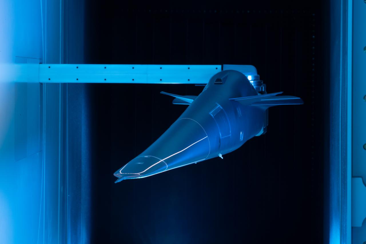
Event: Forebody and Nose - Windtunnel Testing A model of the X-59 forebody is shown in the Lockheed Martin Skunk Works’ wind tunnel in Palmdale, California. These tests gave the team measurements of wind flow angle around the aircraft’s nose and confirmed computer predictions made using computational fluid dynamics (CFD) software tools. The data will be fed into the aircraft flight control system to tell the pilot the aircraft’s altitude, speed and angle. This is part of NASA’s Quesst mission which plans to help enable supersonic air travel over land.
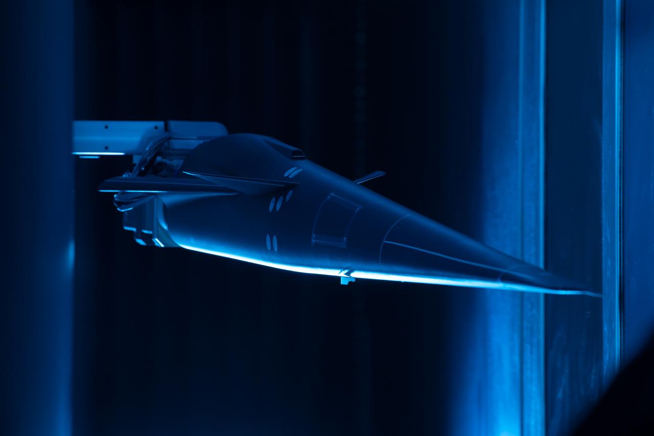
Event: Forebody and Nose - Windtunnel Testing A model of the X-59 forebody is shown in the Lockheed Martin Skunk Works’ wind tunnel in Palmdale, California. These tests gave the team measurements of wind flow angle around the aircraft’s nose and confirmed computer predictions made using computational fluid dynamics (CFD) software tools. The data will be fed into the aircraft flight control system to tell the pilot the aircraft’s altitude, speed and angle. This is part of NASA’s Quesst mission which plans to help enable supersonic air travel over land.
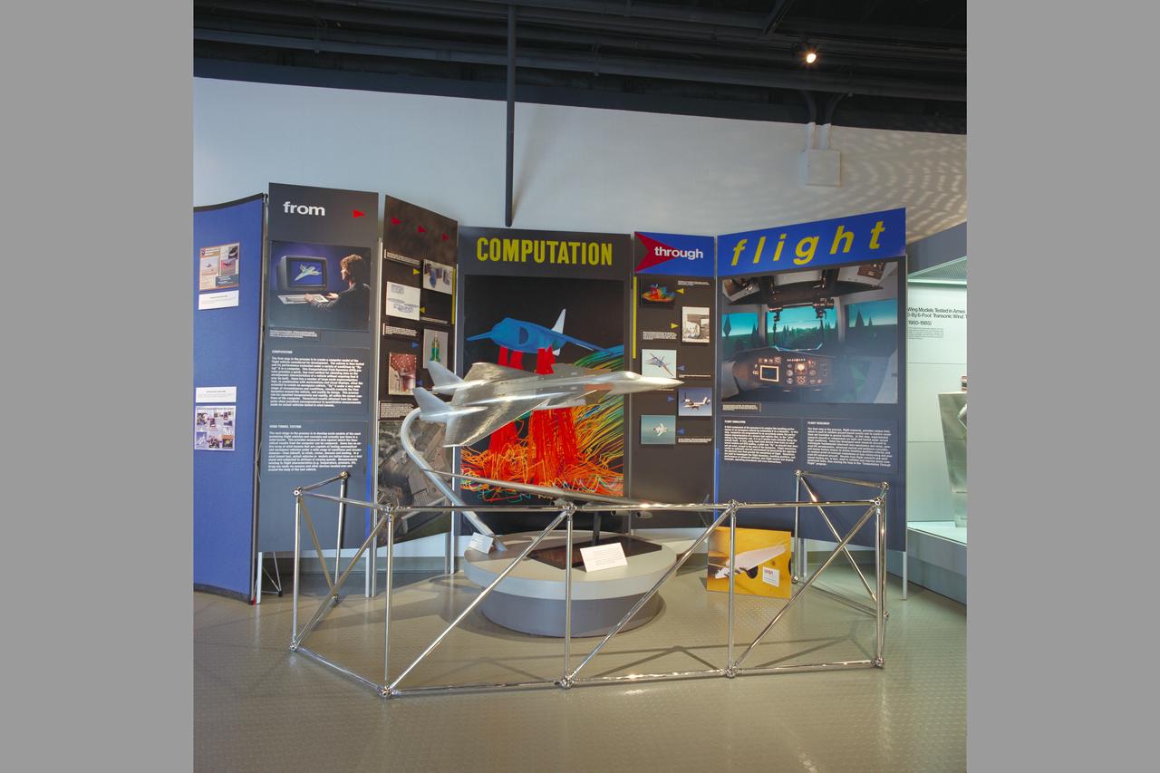
N-233 Visitor Information Center (VIC): Grom Computation to Flight Exhibit with the F-18 wt model
A computer model for the protein crystal trypanathione reductase, which is being studied in an effort to devise a treatment for Chaga's disease, a devastation illness caused by a parasite.
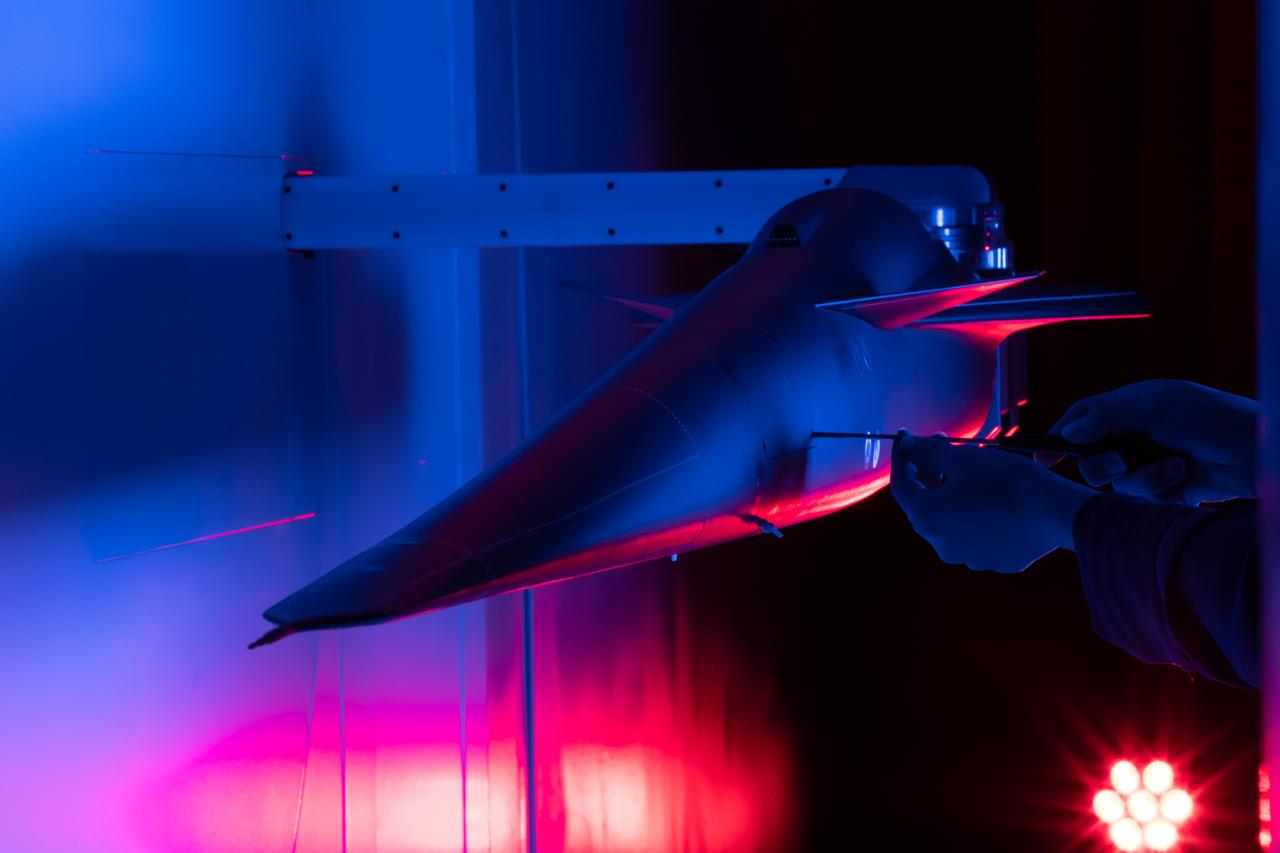
Event: Forebody and Nose - Windtunnel Testing A technician works on the X-59 model during testing in the low-speed wind tunnel at Lockheed Martin Skunk Works in Palmdale, California. These tests gave the team measurements of wind flow angle around the aircraft’s nose and confirmed computer predictions made using computational fluid dynamics (CFD) software tools. The data will be fed into the aircraft flight control system to tell the pilot the aircraft’s altitude, speed, and angle. This is part of NASA’s Quesst mission which plans to help enable supersonic air travel over land.
jsc2021e031157 (7/22/2021) --- A view of the KREP Ecapsule model. The Kentucky Re-Entry Probe Experiment (KREPE) demonstrates an affordable technology for re-entry experiments and provides flight data on Thermal Protection Systems (TPS) to help validate computational models. Photo courtesy of the University of Kentucky.

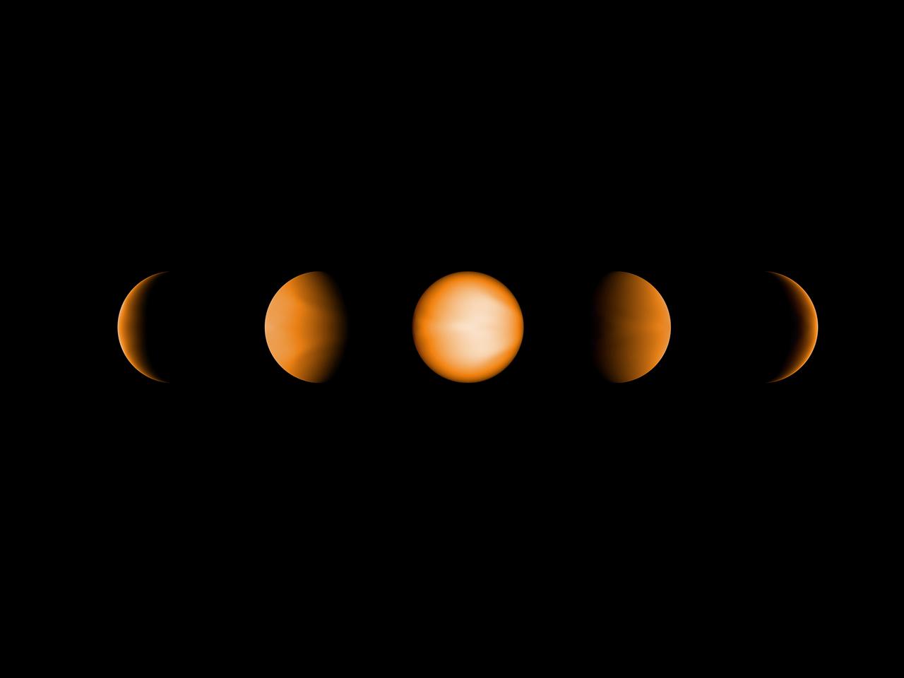
Hot Jupiters are exoplanets that orbit their stars so tightly that their temperatures are extremely high, reaching over 2,400 degrees Fahrenheit (1600 Kelvin). They are also tidally locked, so one side of the planet always faces the sun and the other is in permanent darkness. Research suggests that the "dayside" is largely free of clouds, while the "nightside" is heavily clouded. This illustration represents how hot Jupiters of different temperatures and different cloud compositions might appear to a person flying over the dayside of these planets on a spaceship, based on computer modeling. Cooler planets are entirely cloudy, whereas hotter planets have morning clouds only. Clouds of different composition have different colors, whereas the clear sky is bluer than on Earth. For the hottest planets, the atmosphere is hot enough on the evening side to glow like a charcoal. Figure 1 shows an approximation of what various hot Jupiters might look like based on a combination of computer modeling and data from NASA's Kepler Space Telescope. From left to right it shows: sodium sulfide clouds (1000 to 1200 Kelvin), manganese sulfide clouds (1200 to 1600 Kelvin), magnesium silicate clouds (1600 to 1800 Kelvin), magnesium silicate and aluminum oxide clouds (1800 Kelvin) and clouds composed of magnesium silicate, aluminum oxide, iron and calcium titanate (1900 to 2200 Kelvin). http://photojournal.jpl.nasa.gov/catalog/PIA21074

NASA's Solar Dynamics Observatory (SDO) scientists use their computer models to generate a view of the sun's magnetic field (Aug. 10, 2018). We took the opportunity to compare an extreme ultraviolet view of the sun with the same image showing the superimposed field lines. The bright active region right at the central area of the sun clearly shows a concentration of field lines, as well as the small active region at the sun's right edge, but to a lesser extent. Magnetism drives the dynamic activity near the sun's surface. Movies are available at https://photojournal.jpl.nasa.gov/catalog/PIA22662
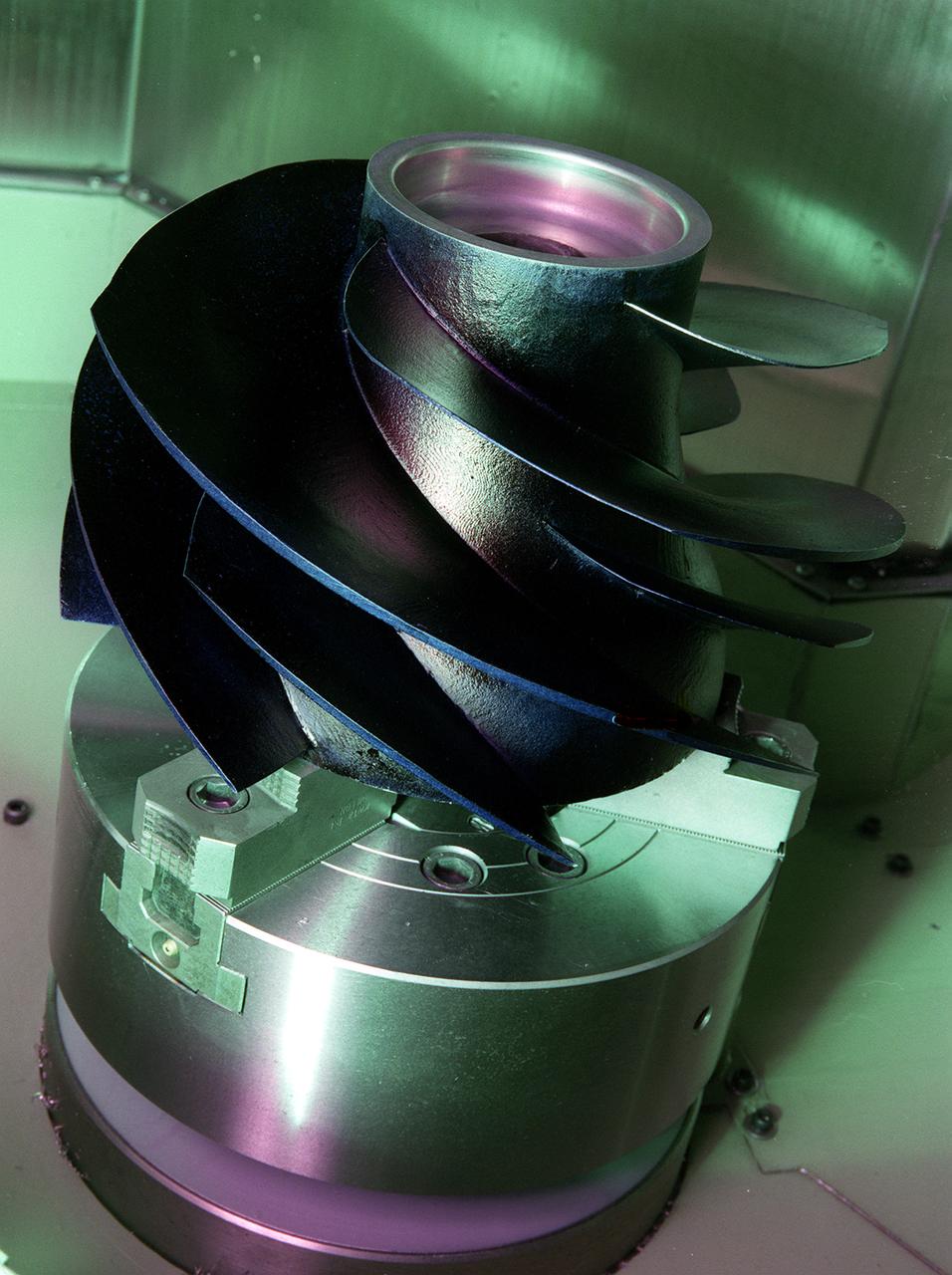
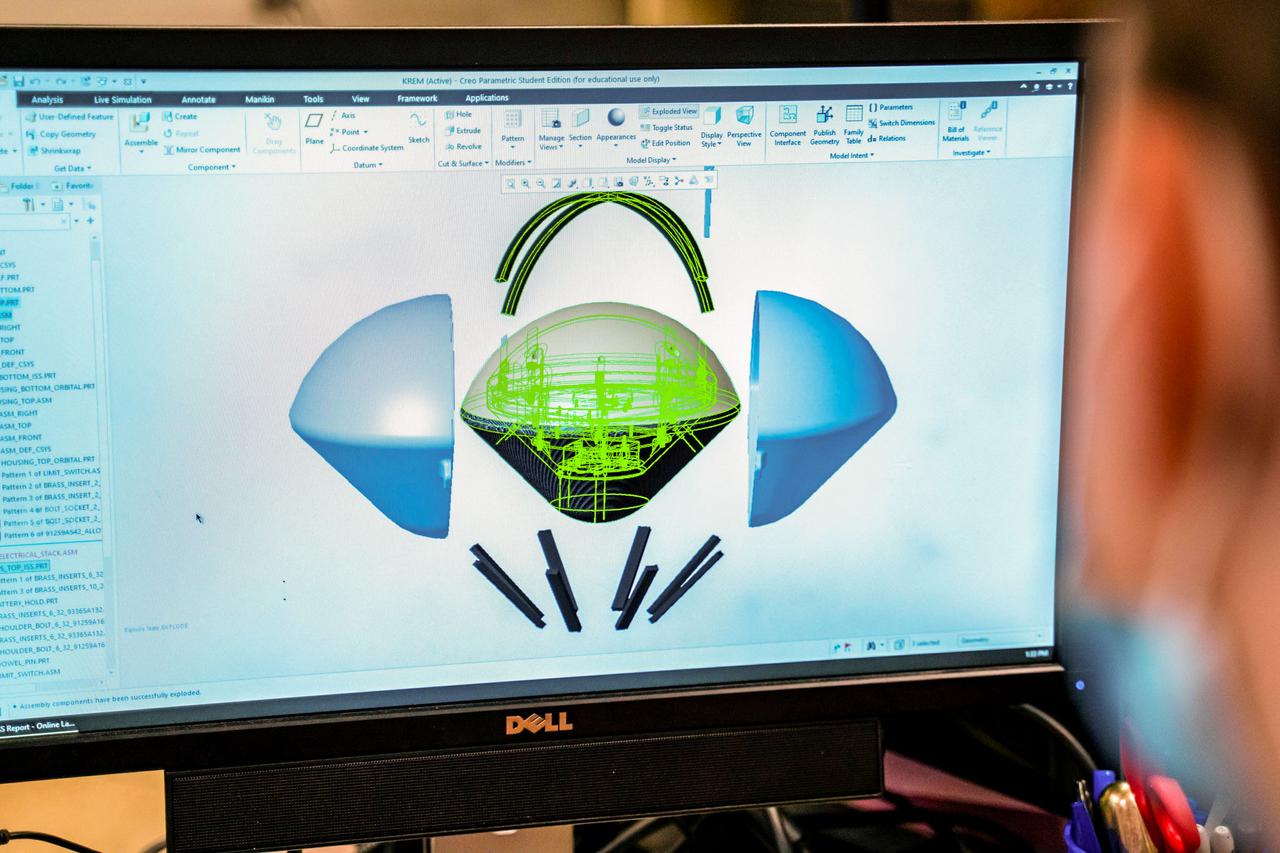
Marshall space Flight Center engineers helped North American Marine Jet (NAMJ), Inc. improve the proposed design of a new impeller for a jet-propulsion system. With a three-dimensional computer model of the new marine jet engine blades, engineers were able to quickly create a solid polycarbonate model of it. The rapid prototyping allowed the company to avoid many time-consuming and costly steps in creating the impeller.
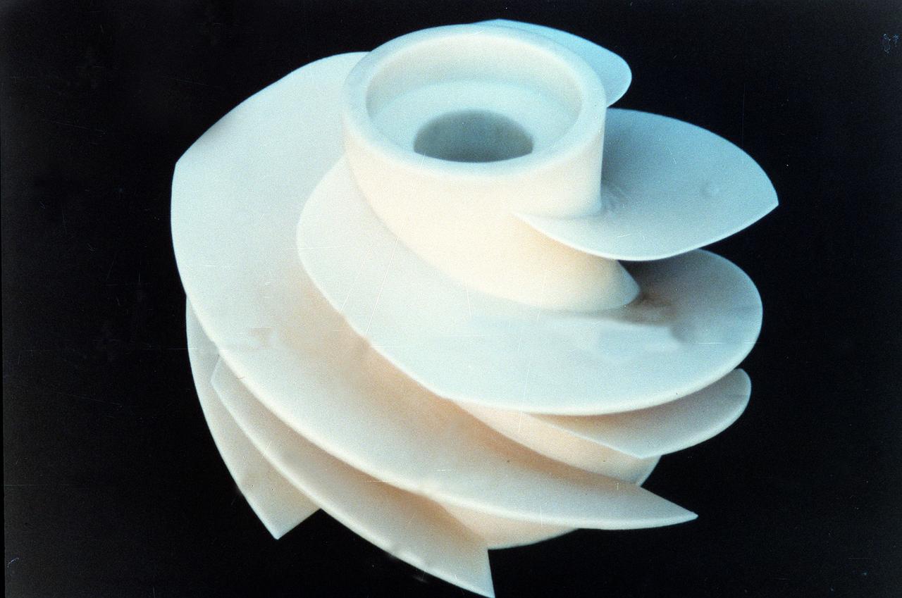
Marshall Space Flight Center engineers helped North American Marine Jet (NAMJ), Inc. improve the proposed design of a new impeller for jet propulsion system. With a three-dimensional computer model of the new marine jet engine blades, engineers were able to quickly create a solid ploycarbonate model of it. The rapid prototyping allowed the company to avoid many time-consuming and costly steps in creating the impeller.
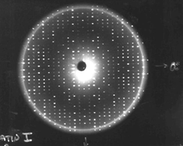
X-rays diffracted from a well-ordered protein crystal create sharp patterns of scattered light on film. A computer can use these patterns to generate a model of a protein molecule. To analyze the selected crystal, an X-ray crystallographer shines X-rays through the crystal. Unlike a single dental X-ray, which produces a shadow image of a tooth, these X-rays have to be taken many times from different angles to produce a pattern from the scattered light, a map of the intensity of the X-rays after they diffract through the crystal. The X-rays bounce off the electron clouds that form the outer structure of each atom. A flawed crystal will yield a blurry pattern; a well-ordered protein crystal yields a series of sharp diffraction patterns. From these patterns, researchers build an electron density map. With powerful computers and a lot of calculations, scientists can use the electron density patterns to determine the structure of the protein and make a computer-generated model of the structure. The models let researchers improve their understanding of how the protein functions. They also allow scientists to look for receptor sites and active areas that control a protein's function and role in the progress of diseases. From there, pharmaceutical researchers can design molecules that fit the active site, much like a key and lock, so that the protein is locked without affecting the rest of the body. This is called structure-based drug design.
VSHAIP test in 7x10ft#1 W.T. (multiple model configruations) V-22 helicopter shipboard aerodynamic interaction program: L-R seated Allen Wadcox, (standind) Mark Betzina, seated in front of computer Gloria Yamauchi, in background Kurt Long.
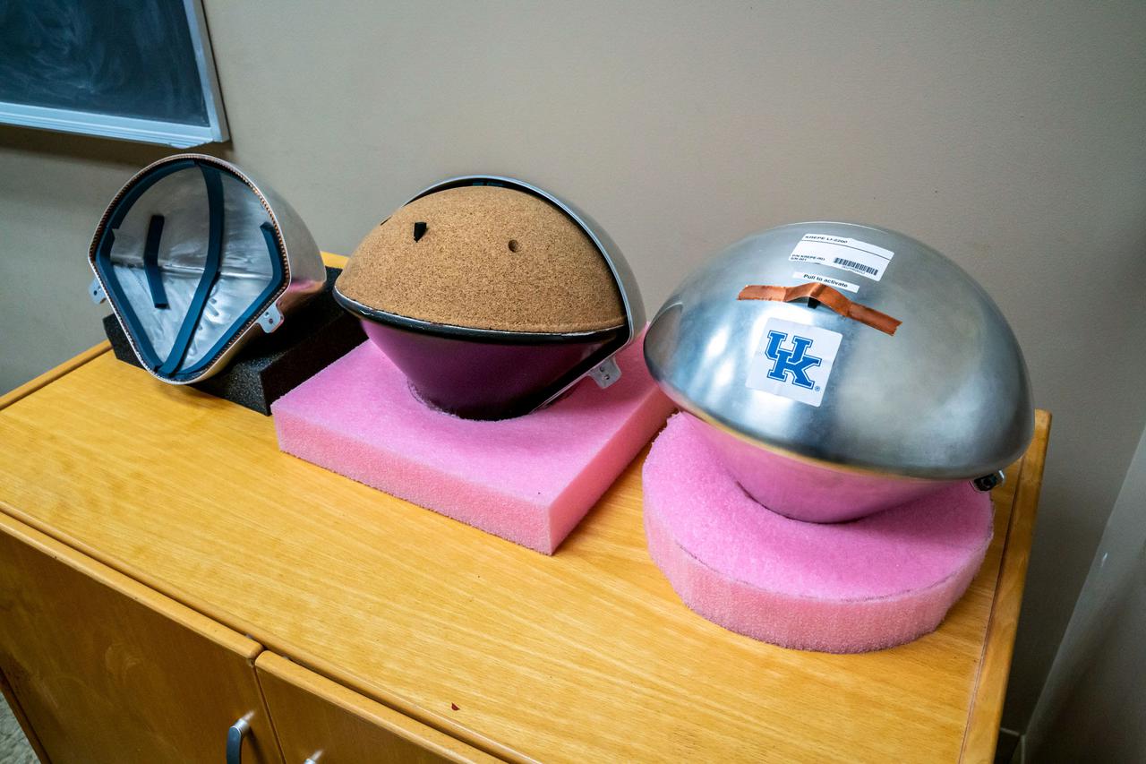
jsc2021e031158 (7/22/2021) --- A preflight view of the heat-shield on the KREPE Capsule. The Kentucky Re-Entry Probe Experiment (KREPE) demonstrates an affordable technology for re-entry experiments and provides flight data on Thermal Protection Systems (TPS) to help validate computational models. Photo courtesy of the University of Kentucky.
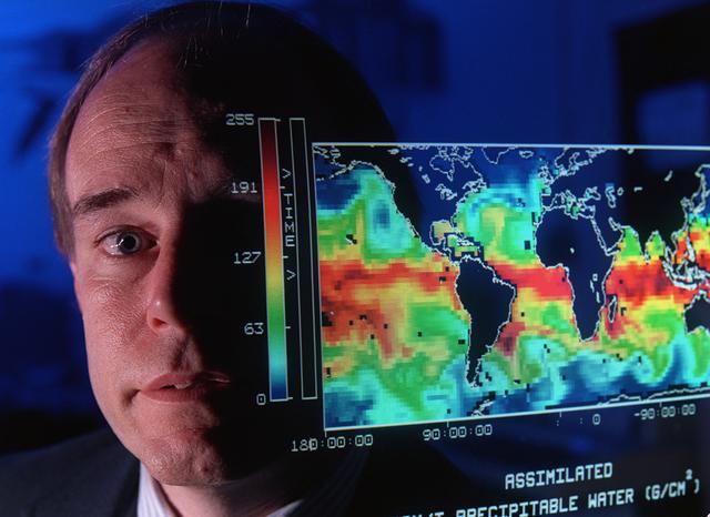
This map shows the presence of water vapor over global oceans. The imagery was produced by combining Special Sensor Microwave Imager measurements and computer models. This data will help scientists better understand how weather systems move water vapor from the tropics toward the poles producing precipitation.

Barbara Marino (left), Stennis Space Center education technology specialist, shows Astro Camp Counselor Beverly Fitzsimmons a LEGO model during a teambuilding exercise May 29 at SSC's North Gate computer lab as a part of the counselors' `new hire' orientation.
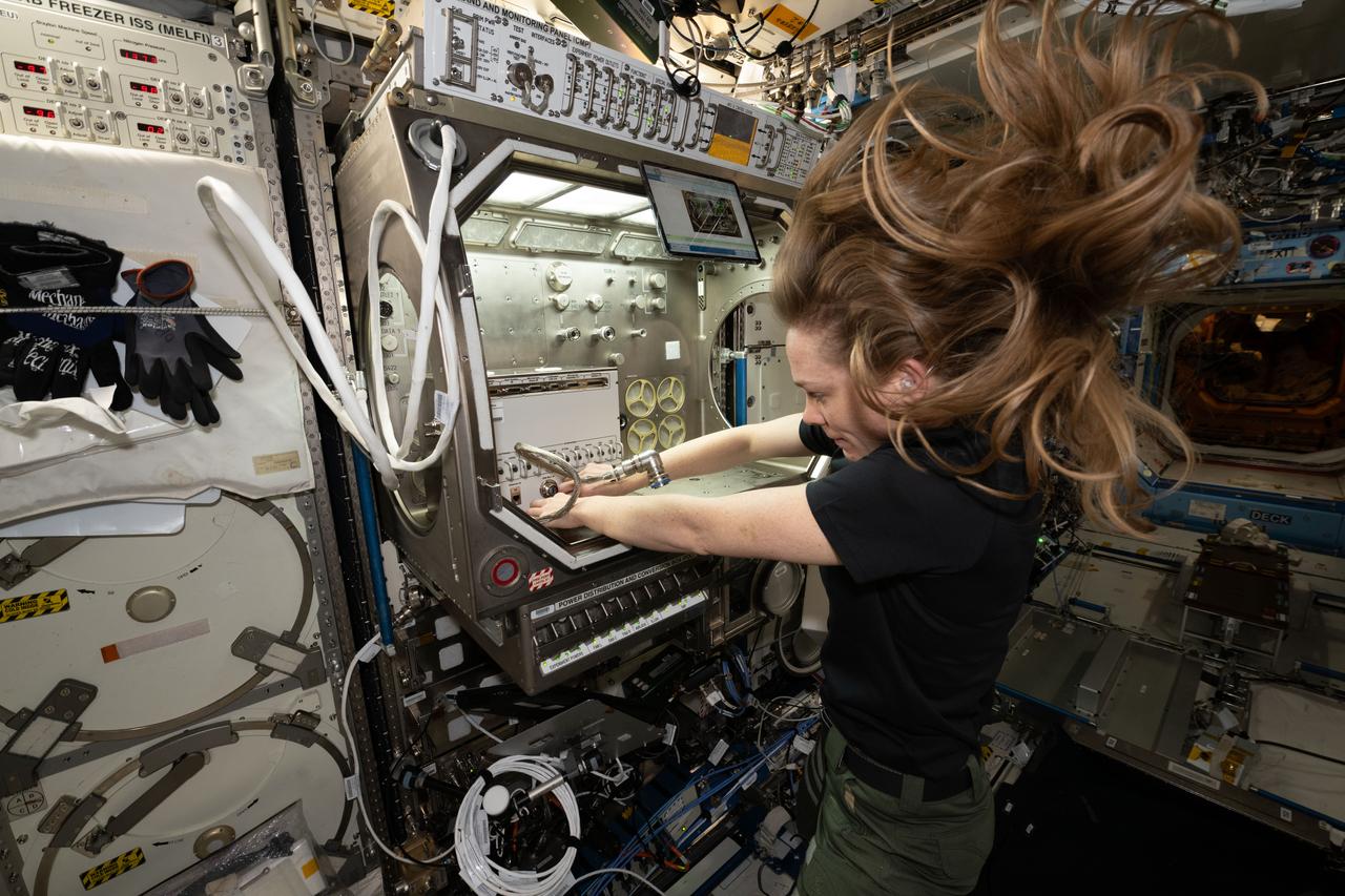
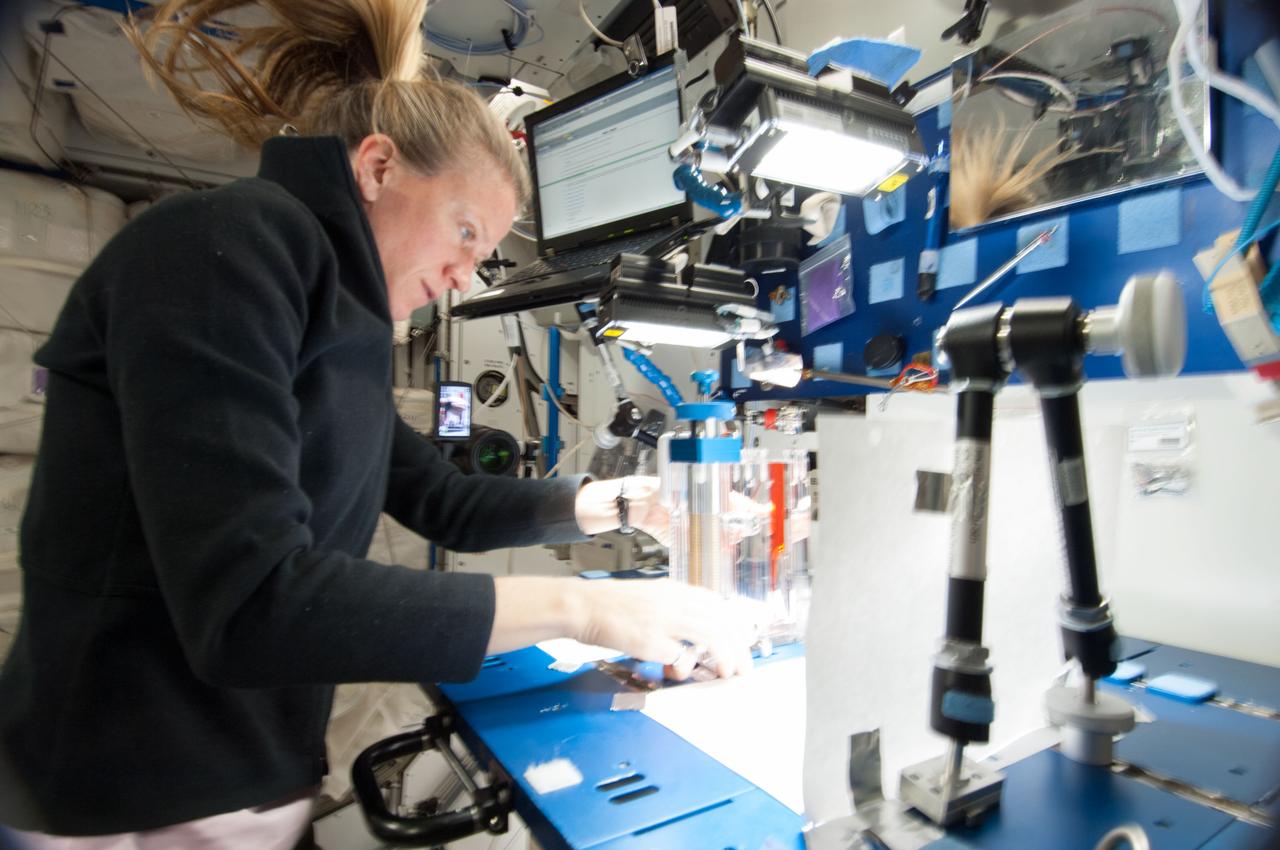
iss073e0134929 (6/9/2025) ---NASA astronaut Nichole Ayers sets up the station’s Ring Sheared Drop module. This system makes it possible to study liquid protein solutions without using containers, eliminating interactions between the solutions and container walls that can affect results. Ring Sheared Drop-IBP-2 studies the behavior of protein fluids in microgravity and tests computer models to predict that fluid’s behavior. Better models could help could advance manufacturing processes in space and on Earth for producing next-generation medicines for treating cancers and other diseases.NASA astronaut Nichole Ayers sets up the station’s Ring Sheared Drop module. This system makes it possible to study liquid protein solutions without using containers, eliminating interactions between the solutions and container walls that can affect results. Ring Sheared Drop-IBP-2 studies the behavior of protein fluids in microgravity and tests computer models to predict that fluid’s behavior. Better models could help could advance manufacturing processes in space and on Earth for producing next-generation medicines for treating cancers and other diseases.
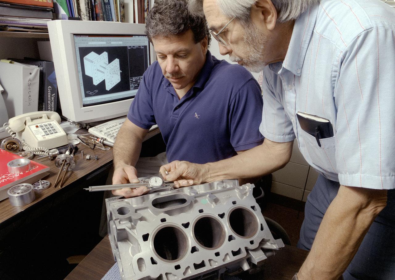
Don Sirois, an Auburn University research associate, and Bruce Strom, a mechanical engineering Co-Op Student, are evaluating the dimensional characteristics of an aluminum automobile engine casting. More accurate metal casting processes may reduce the weight of some cast metal products used in automobiles, such as engines. Research in low gravity has taken an important first step toward making metal products used in homes, automobiles, and aircraft less expensive, safer, and more durable. Auburn University and industry are partnering with NASA to develop one of the first accurate computer model predictions of molten metals and molding materials used in a manufacturing process called casting. Ford Motor Company's casting plant in Cleveland, Ohio is using NASA-sponsored computer modeling information to improve the casting process of automobile and light-truck engine blocks.
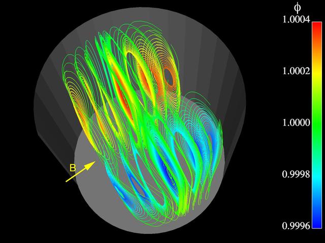
Advanced finite element models are used to study three-dimensional, time-dependent flow and segregation in crystal growth systems. In this image of a prototypical model for melt and crystal growth, pathlines at one instant in time are shown for the flow of heated liquid silicon in a cylindrical container. The container is subjected to g-jitter disturbances along the vertical axis. A transverse magnetic field is applied to control them. Such computations are extremely powerful for understanding melt growth in microgravity where g-jitter drives buoyant flows. The simulation is part of the Theoretical Analysis of 3D, Transient Convection and Segregation in Microgravity Bridgman Crystal Growth investigation by Dr. Jeffrey J. Derby of the University of Mirnesota, Minneapolis.
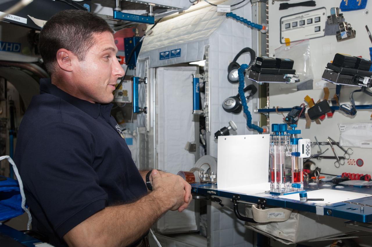
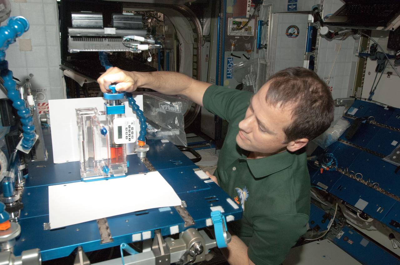
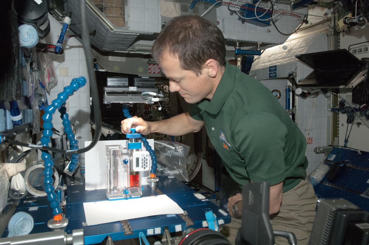
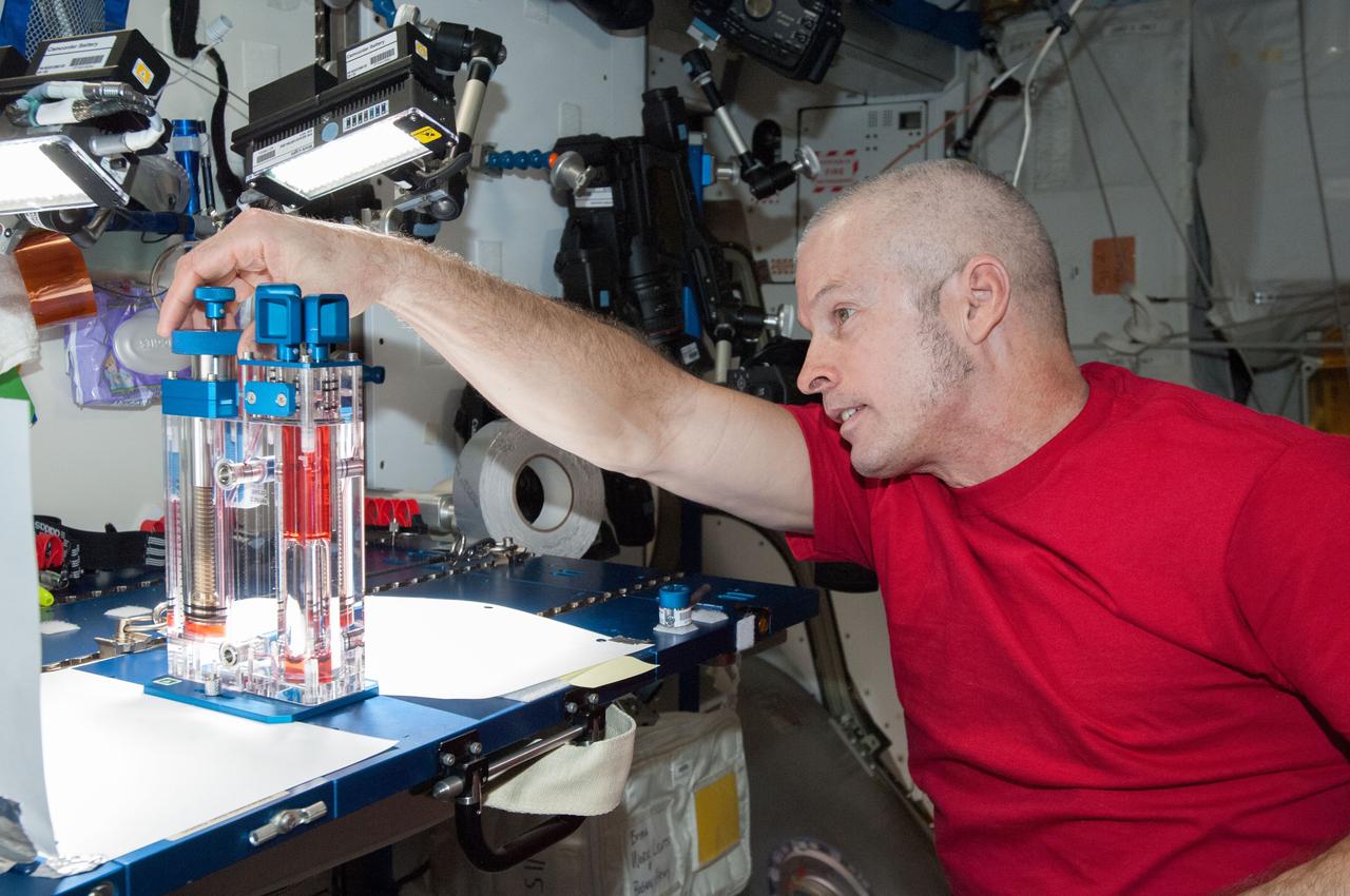
ISS038-E-000263 (11 Nov. 2013) --- NASA astronaut Michael Hopkins, Expedition 38 flight engineer, conducts a session with the Capillary Flow Experiment (CFE) in the Harmony node of the International Space Station. CFE is a suite of fluid physics experiments that investigate how fluids move up surfaces in microgravity. The results aim to improve current computer models that are used by designers of low gravity fluid systems and may improve fluid transfer systems for water on future spacecraft.
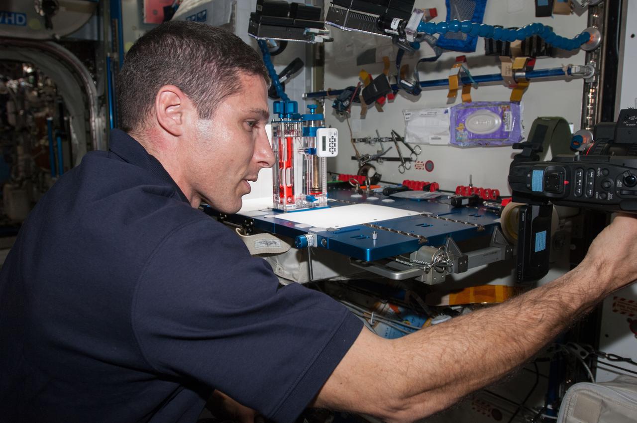
ISS038-E-000269 (11 Nov. 2013) --- NASA astronaut Michael Hopkins, Expedition 38 flight engineer, conducts a session with the Capillary Flow Experiment (CFE) in the Harmony node of the International Space Station. CFE is a suite of fluid physics experiments that investigate how fluids move up surfaces in microgravity. The results aim to improve current computer models that are used by designers of low gravity fluid systems and may improve fluid transfer systems for water on future spacecraft.
ISS034-E-036844 (29 Jan. 2013) --- In the International Space Station’s Harmony node, NASA astronaut Tom Marshburn, Expedition 34 flight engineer, works with the Capillary Flow Experiment-3, which investigates how fluids flow across surfaces in a weightless environment. Results from this experiment will improve computer models used to design fluid transfer systems and fuel tanks on future spacecraft.
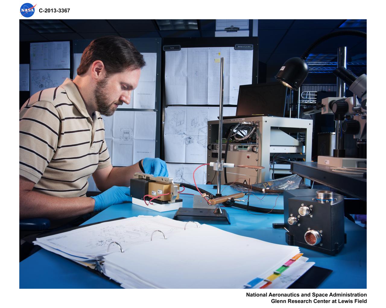
Mechanical Engineer Adrian Drake inspects engineering model hardware built to generate a high-voltage electric field for the Electric-Field Effects on Laminar Diffusion Flames (E-FIELD Flames) experiment of the Advanced Combustion via Microgravity Experiments (ACME) project. ACME’s small computer (i.e., the Cube) for data acquisition and control within the CIR combustion chamber is seen in the right foreground. The E-FIELD Flames tests were conducted in the Combustion Integrated Rack (CIR) on the International Space Station (ISS) in 2018.
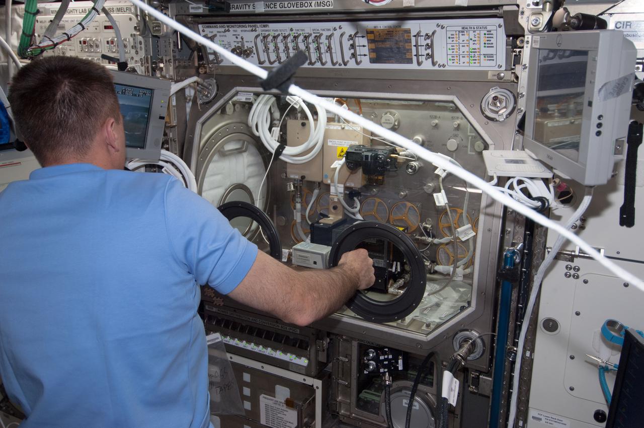
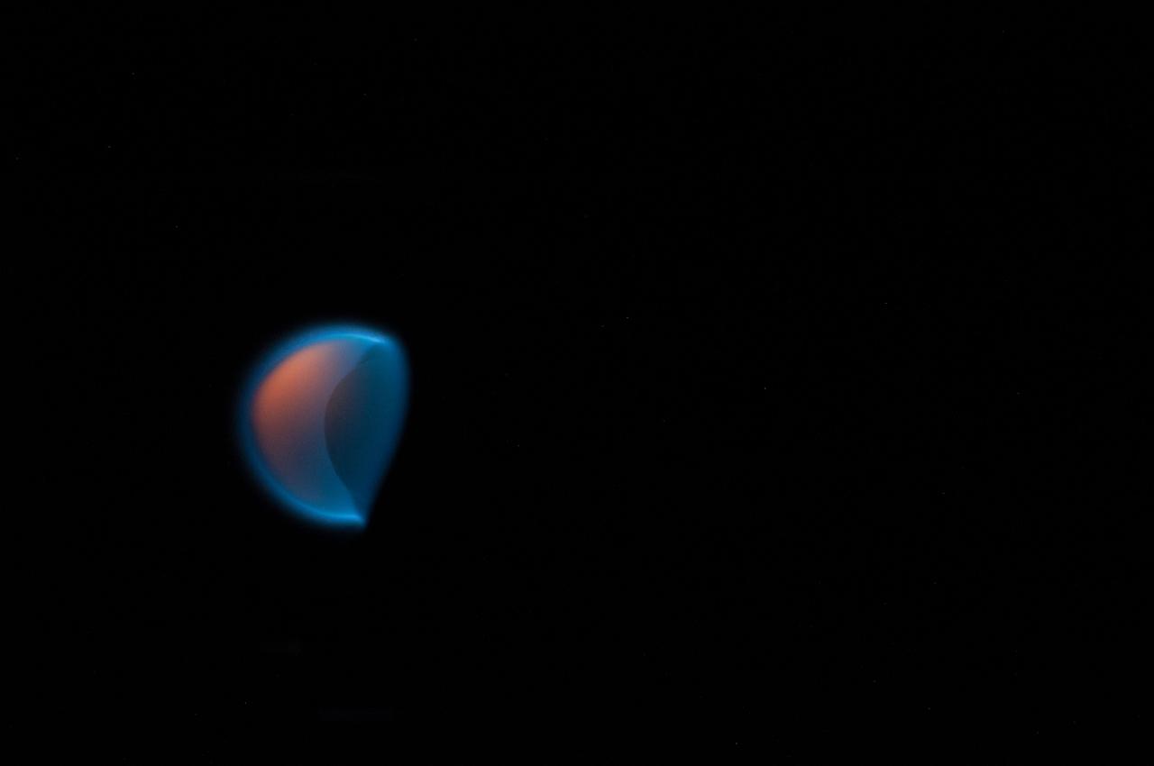
ISS035-E-015081 (5 April 2013) --- Astronaut Chris Cassidy, Expedition 35 flight engineer, conducts a session of the Burning and Suppression of Solids (BASS) experiment onboard the Earth-orbiting International Space Station. Following a series of preparations, Cassidy conducted a run of the experiment, which examined the burning and extinction characteristics of a wide variety of fuel samples in microgravity and will guide strategies for extinguishing fires in microgravity. BASS results contribute to the combustion computational models used in the design of fire detection and suppression systems in microgravity and on Earth.
![SCI2016_0001: SOFIA/GREAT [O I] spectrum at 4.7 THz (63 μm) superimposed on a picture of Mars. Absorption line depth is approximately 10% of the continuum. The abundance of atomic oxygen computed from the data is less than expected from the Forget et al. 1999 global circulation & photochemical model. Credit: SOFIA/GREAT spectrum: NASA/DLR/USRA/DSI/MPIfR/GREAT Consortium/MPIfS/Rezac et al. 2015; Mars image: NASA](https://images-assets.nasa.gov/image/ACD17-0168-003/ACD17-0168-003~medium.jpg)
SCI2016_0001: SOFIA/GREAT [O I] spectrum at 4.7 THz (63 μm) superimposed on a picture of Mars. Absorption line depth is approximately 10% of the continuum. The abundance of atomic oxygen computed from the data is less than expected from the Forget et al. 1999 global circulation & photochemical model. Credit: SOFIA/GREAT spectrum: NASA/DLR/USRA/DSI/MPIfR/GREAT Consortium/MPIfS/Rezac et al. 2015; Mars image: NASA
ISS040-E-032820 (3 July 2014) --- NASA astronaut Steve Swanson, Expedition 40 commander, conducts a session with the Capillary Flow Experiment (CFE) in the Harmony node of the International Space Station. CFE is a suite of fluid physics experiments that investigate how fluids move up surfaces in microgravity. The results aim to improve current computer models that are used by designers of low gravity fluid systems and may improve fluid transfer systems for water on future spacecraft.
jsc2021e031159 (7/22/2021) --- John Schmidt, graduate student and mechanical engineering lead and Matthew Ruffner, graduate student and electrical engineering lead of KREPE. The Kentucky Re-Entry Probe Experiment (KREPE) demonstrates an affordable technology for re-entry experiments and provides flight data on Thermal Protection Systems (TPS) to help validate computational models. Photo courtesy of the University of Kentucky.
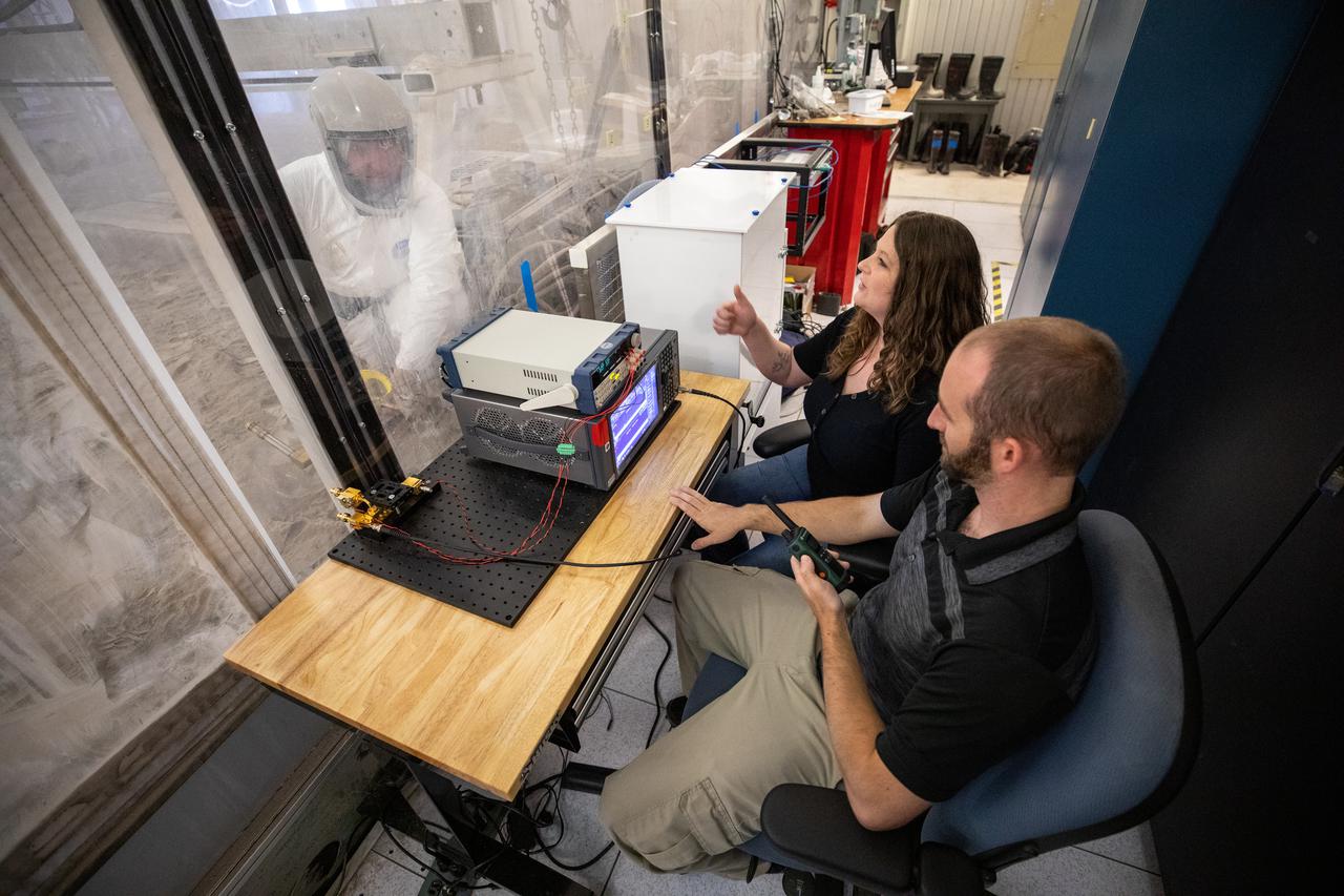
Beverly Kemmerer and Austin Adkins, right, and Austin Langton, perform testing with a Millimeter Wave Doppler Radar at NASA’s Kennedy Space Center’s Granular Mechanics and Regolith Operations Lab on July 16, 2021. The testing at the Florida spaceport is part of a project to identify a suite of instrumentation capable of acquiring a comprehensive set of flight data from a lunar lander. Researchers at NASA will use that data to validate computational models being developed to predict plume surface interaction effects on the Moon.
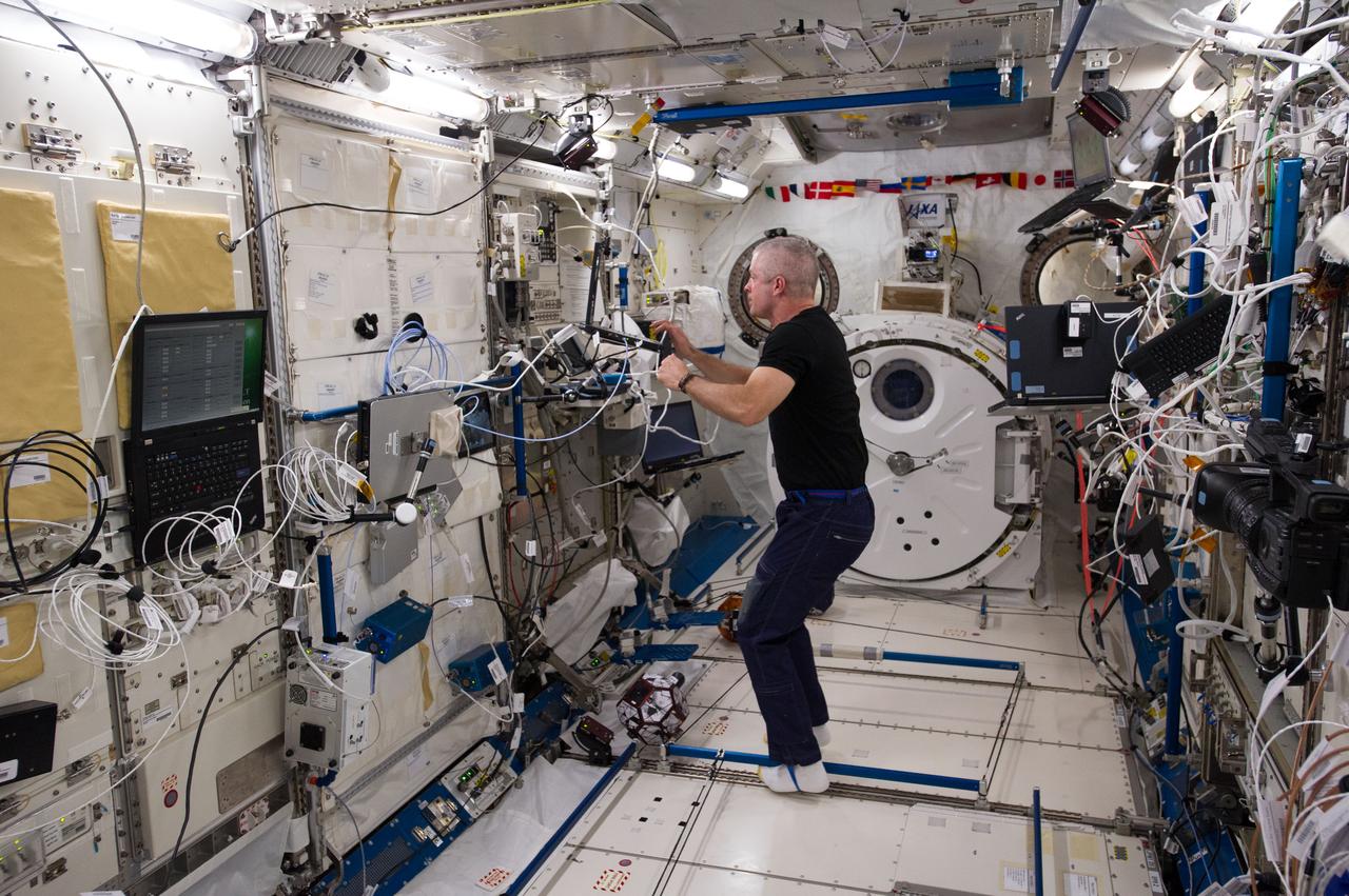
ISS040-E-079083 (25 July 2014) --- In the International Space Station?s Kibo laboratory, NASA astronaut Steve Swanson, Expedition 40 commander, enters data in a computer in preparation for a session with a trio of soccer-ball-sized robots known as the Synchronized Position Hold, Engage, Reorient, Experimental Satellites, or SPHERES. The free-flying robots were equipped with stereoscopic goggles called the Visual Estimation and Relative Tracking for Inspection of Generic Objects, or VERTIGO, to enable the SPHERES to perform relative navigation based on a 3D model of a target object.
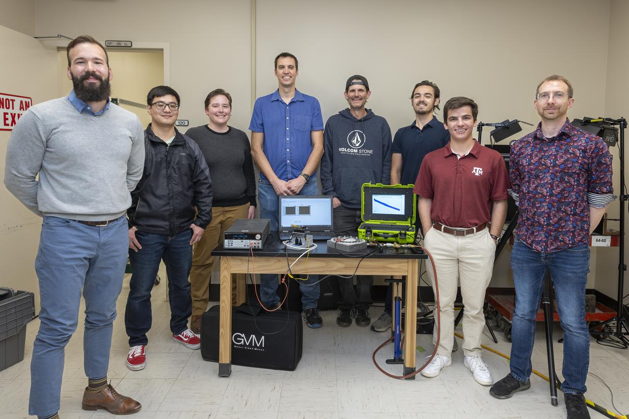
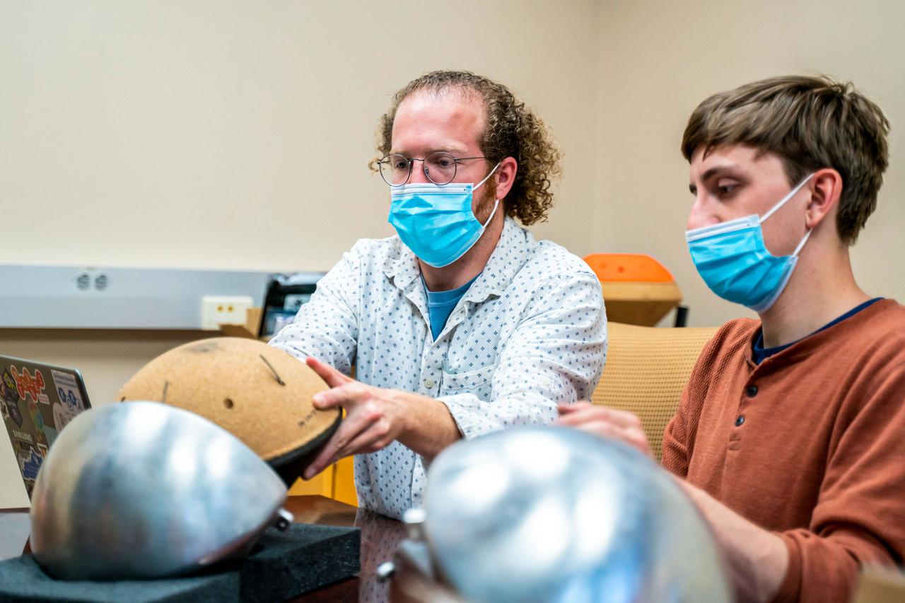
Erick Rossi De La Fuente, from left, John Rudy, L. J. Hantsche, Adam Curry, Jeff Howell, Coby Asselin, Benjamin Mayeux, and Paul Bean pose with a test fixture, material, sensor, and data acquisition systems at NASA’s Armstrong Flight Research Center in Edwards, California. The sensor tests seek to quantify the limits of the material to improve computer models and make more reliable supersonic parachutes.

CAPE CANAVERAL, Fla. – Tracey Kickbusch, chief of computational sciences at NASA's Kennedy Space Center in Florida, discusses modeling and simulations with attendees at the Technology Transfer Forum of the Economic Development Commission of Florida's Space Coast. A goal of the session was to showcase ways commercial businesses can work with NASA to develop technology and apply existing technology to commercial uses. Photo credit: NASA/Glenn Benson
ISS036-E-029767 (8 Aug. 2013) --- NASA astronaut Karen Nyberg, Expedition 36 flight engineer, conducts a session with the Capillary Flow Experiment (CFE) in the Harmony node of the International Space Station. CFE observes the flow of fluid, in particular capillary phenomena, in microgravity. The data from this experiment will improve computer models used to design fluid transfer systems and fuel tanks on future spacecraft.
ISS034-E-036840 (29 Jan. 2013) --- In the International Space Station?s Harmony node, NASA astronaut Tom Marshburn, Expedition 34 flight engineer, works with the Capillary Flow Experiment-3, which investigates how fluids flow across surfaces in a weightless environment. Results from this experiment will improve computer models used to design fluid transfer systems and fuel tanks on future spacecraft.
ISS036-E-029774 (8 Aug. 2013) --- NASA astronaut Karen Nyberg, Expedition 36 flight engineer, conducts a session with the Capillary Flow Experiment (CFE) in the Harmony node of the International Space Station. CFE observes the flow of fluid, in particular capillary phenomena, in microgravity. The data from this experiment will improve computer models used to design fluid transfer systems and fuel tanks on future spacecraft.
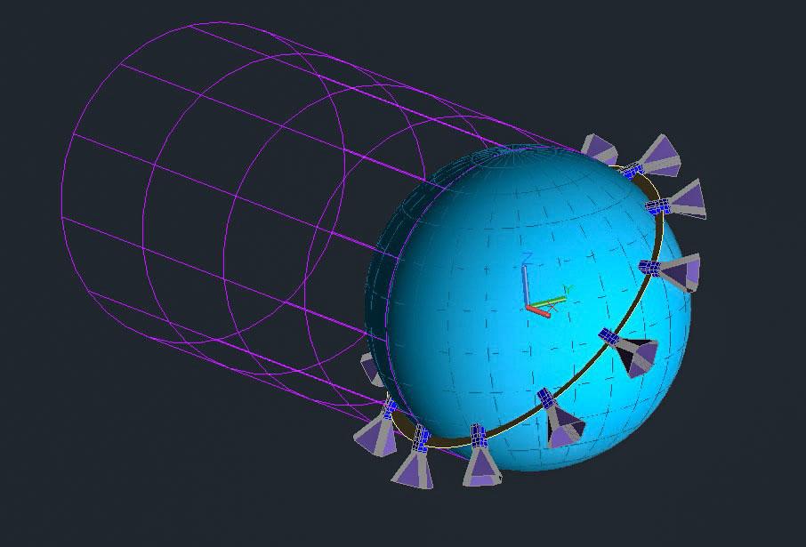
Jsc2020e004943 (2/7/2020) — A computer model showing CryoCube’s orbital orientation. CryoCube demonstrates on-orbit thermal management technology. Such technology has a variety of potential applications, including storing rocket propellants in space, cooling instruments to improve their signal-to-noise ratios, and supporting future cryogenic experiments in microgravity. The small satellite uses a deployable shield to block radiation from the Sun and Earth and an attitude control system to point its experiment into deep space. Image courtesy of : Kennedy Space Center
ISS040-E-032827 (3 July 2014) --- NASA astronaut Steve Swanson, Expedition 40 commander, conducts a session with the Capillary Flow Experiment (CFE) in the Harmony node of the International Space Station. CFE is a suite of fluid physics experiments that investigate how fluids move up surfaces in microgravity. The results aim to improve current computer models that are used by designers of low gravity fluid systems and may improve fluid transfer systems for water on future spacecraft.
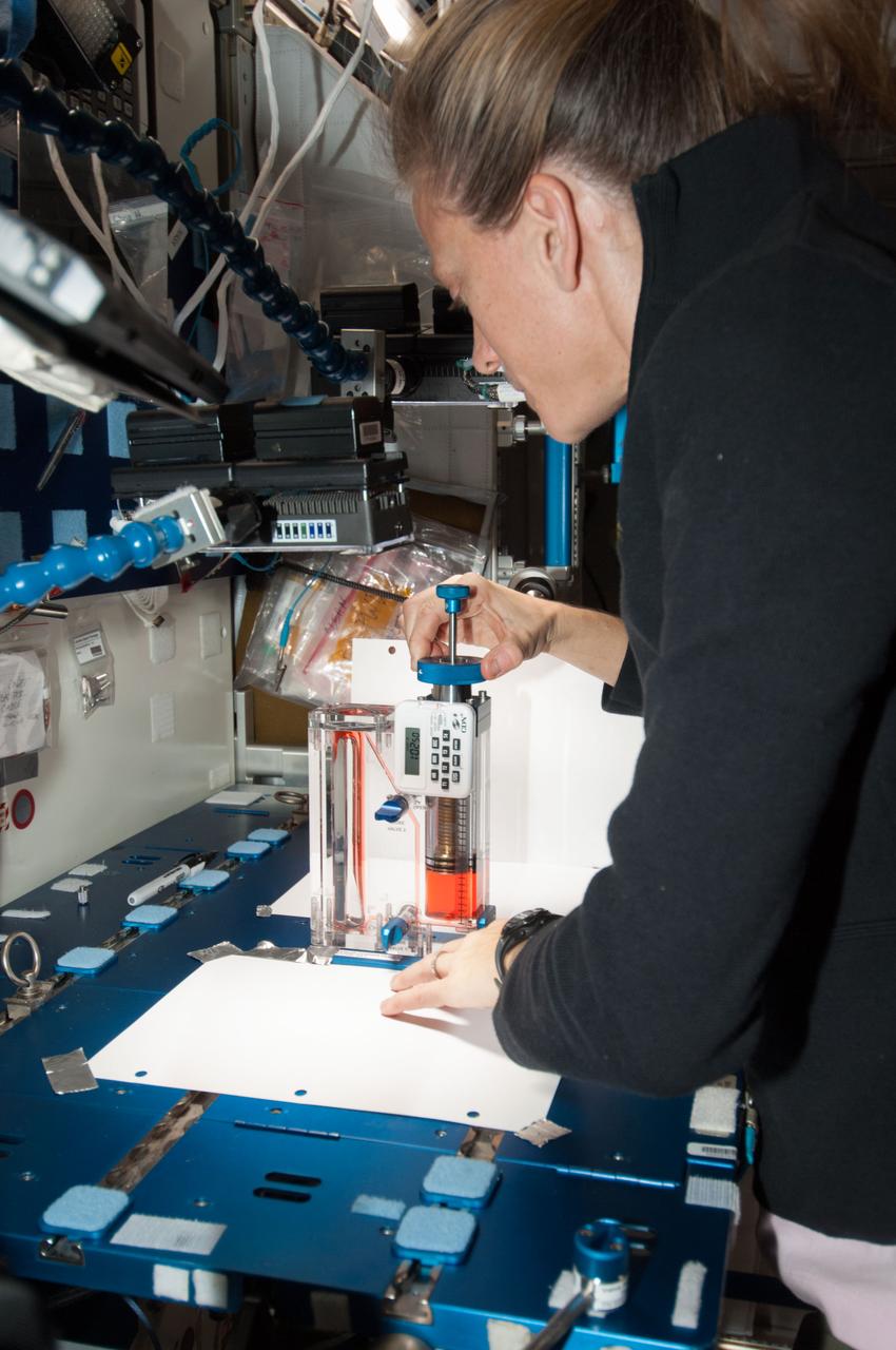
ISS036-E-029773 (8 Aug. 2013) --- NASA astronaut Karen Nyberg, Expedition 36 flight engineer, conducts a session with the Capillary Flow Experiment (CFE) in the Harmony node of the International Space Station. CFE observes the flow of fluid, in particular capillary phenomena, in microgravity. The data from this experiment will improve computer models used to design fluid transfer systems and fuel tanks on future spacecraft.
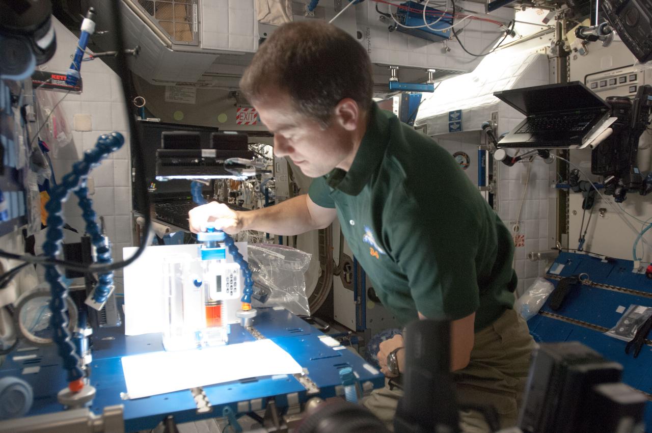
ISS034-E-036841 (29 Jan. 2013) --- In the International Space Station’s Harmony node, NASA astronaut Tom Marshburn, Expedition 34 flight engineer, works with the Capillary Flow Experiment-3, which investigates how fluids flow across surfaces in a weightless environment. Results from this experiment will improve computer models used to design fluid transfer systems and fuel tanks on future spacecraft.
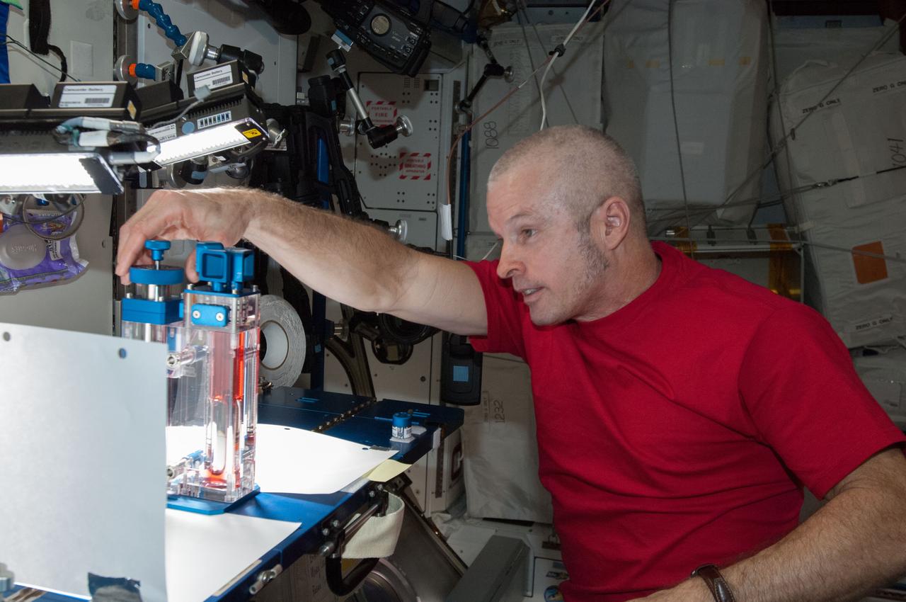
ISS040-E-032825 (3 July 2014) --- NASA astronaut Steve Swanson, Expedition 40 commander, conducts a session with the Capillary Flow Experiment (CFE) in the Harmony node of the International Space Station. CFE is a suite of fluid physics experiments that investigate how fluids move up surfaces in microgravity. The results aim to improve current computer models that are used by designers of low gravity fluid systems and may improve fluid transfer systems for water on future spacecraft.
Coby Asselin, from left, Adam Curry, and L. J. Hantsche set up the data acquisition systems used during testing of a senor to determine parachute canopy material strength at NASA’s Armstrong Flight Research Center in Edwards, California. The sensor tests seek to quantify the limits of the material to improve computer models and make more reliable supersonic parachutes.
Beverly Kemmerer and Austin Adkins perform testing with a Millimeter Wave Doppler Radar at NASA’s Kennedy Space Center’s Granular Mechanics and Regolith Operations Lab on July 16, 2021. The testing at the Florida spaceport is part of a project to identify a suite of instrumentation capable of acquiring a comprehensive set of flight data from a lunar lander. Researchers at NASA will use that data to validate computational models being developed to predict plume surface interaction effects on the Moon.
These simulated views of the ultrahot Jupiter WASP-121b show what the planet might look like to the human eye from five different vantage points, illuminated to different degrees by its parent star. The images were created using a computer simulation being used to help scientists understand the atmospheres of these ultra-hot planets. Ultrahot Jupiters reflect almost no light, rather like charcoal. However, the daysides of ultrahot Jupiters have temperatures of between 3600°F and 5400°F (2000°C and 3000°C), so the planets produce their own glow, like a hot ember. The orange color in this simulated image is thus from the planet's own heat. The computer model was based on observations of WASP-121b conducted using NASA's Spitzer and Hubble space telescopes. https://photojournal.jpl.nasa.gov/catalog/PIA22565
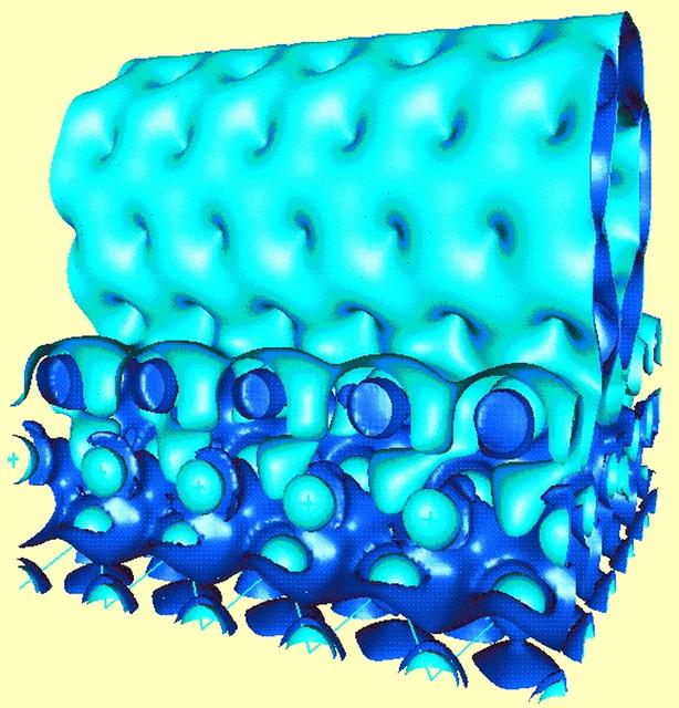
NASA is looking to biological techniques that are millions of years old to help it develop new materials and nanotechnology for the 21st century. Sponsored by NASA, Jerzy Bernholc, a principal investigator in the microgravity materials science program and a physics professor at North Carolina State University, Bernholc works with very large-scale computations to model carbon molecules as they assemble themselves to form nanotubes. The strongest confirmed material known, nanotubes are much stronger than graphite, a more common material made of carbon, and weigh six times less than steel. Nanotubes have potential uses such as strain gauges, advanced electronic devices, amd batteries. The strength, light weight, and conductive qualities of nanotubes, shown in light blue in this computed electron distribution, make them excellent components of nanoscale devices. One way to conduct electricity to such devices is through contact with aluminum, shown in dark blue.
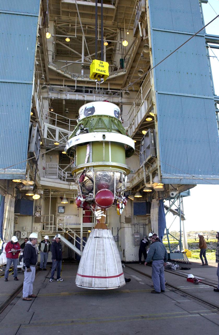
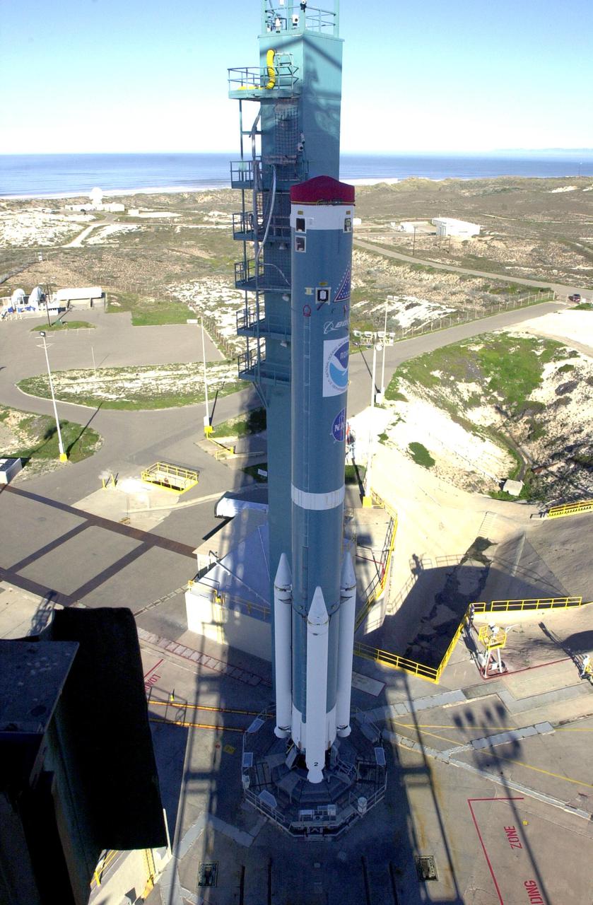
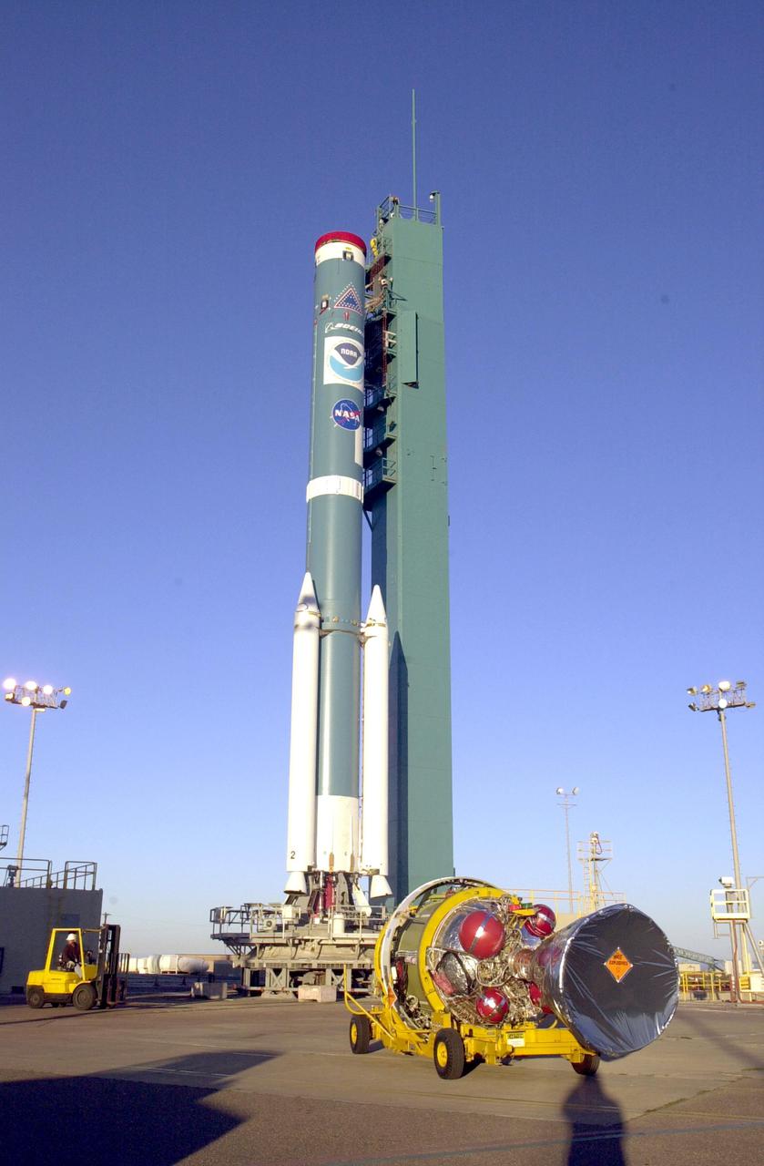
VANDENBERG AIR FORCE BASE, CALIF. - At Space Launch Complex 2 on Vandenberg Air Force Base in California, the second stage of the Boeing Delta II rocket is now suspended vertically and can be lifted up the service tower for mating with the first stage. The Delta II will launch the National Oceanic and Atmospheric Administration (NOAA-N) spacecraft. After launch, NOAA-N will be renamed NOAA-18 and will provide measurements of the Earth's surface and atmosphere that will be entered into NOAA’s weather forecasting models and used for other environmental studies. Each day, the satellite will send data to NOAA’s Command and Data Acquisition station computers, adding vital information to forecasting models, especially over the oceans, where conventional data is lacking. Launch of NOAA-N is scheduled for May 11, 2005.
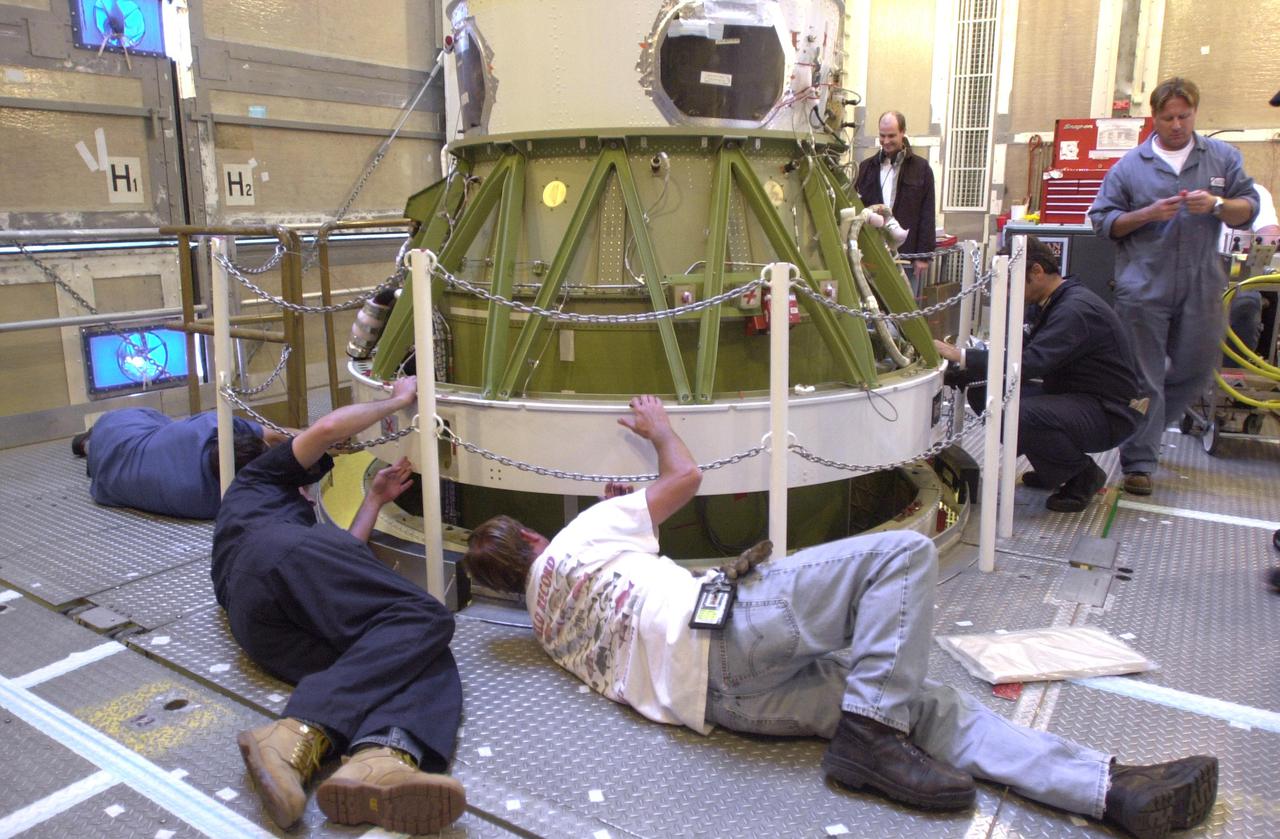
VANDENBERG AIR FORCE BASE, CALIF. - Inside the service tower at Space Launch Complex 2 on Vandenberg Air Force Base in California, Boeing workers get ready to mate the second stage (above) to the first stage of a Boeing Delta II rocket. The Delta II will launch the National Oceanic and Atmospheric Administration (NOAA-N) spacecraft. After launch, NOAA-N will be renamed NOAA-18 and will provide measurements of the Earth's surface and atmosphere that will be entered into NOAA’s weather forecasting models and used for other environmental studies. Each day, the satellite will send data to NOAA’s Command and Data Acquisition station computers, adding vital information to forecasting models, especially over the oceans, where conventional data is lacking. Launch of NOAA-N is scheduled for May 11, 2005.
VANDENBERG AIR FORCE BASE, CALIF. - At Space Launch Complex 2 on Vandenberg Air Force Base in California, Boeing workers help guide the second stage of the Boeing Delta II rocket to a vertical position. The second stage will be lifted and mated with the first stage. The Delta II will launch the National Oceanic and Atmospheric Administration (NOAA-N) spacecraft. After launch, NOAA-N will be renamed NOAA-18 and will provide measurements of the Earth's surface and atmosphere that will be entered into NOAA’s weather forecasting models and used for other environmental studies. Each day, the satellite will send data to NOAA’s Command and Data Acquisition station computers, adding vital information to forecasting models, especially over the oceans, where conventional data is lacking. Launch of NOAA-N is scheduled for May 11, 2005.
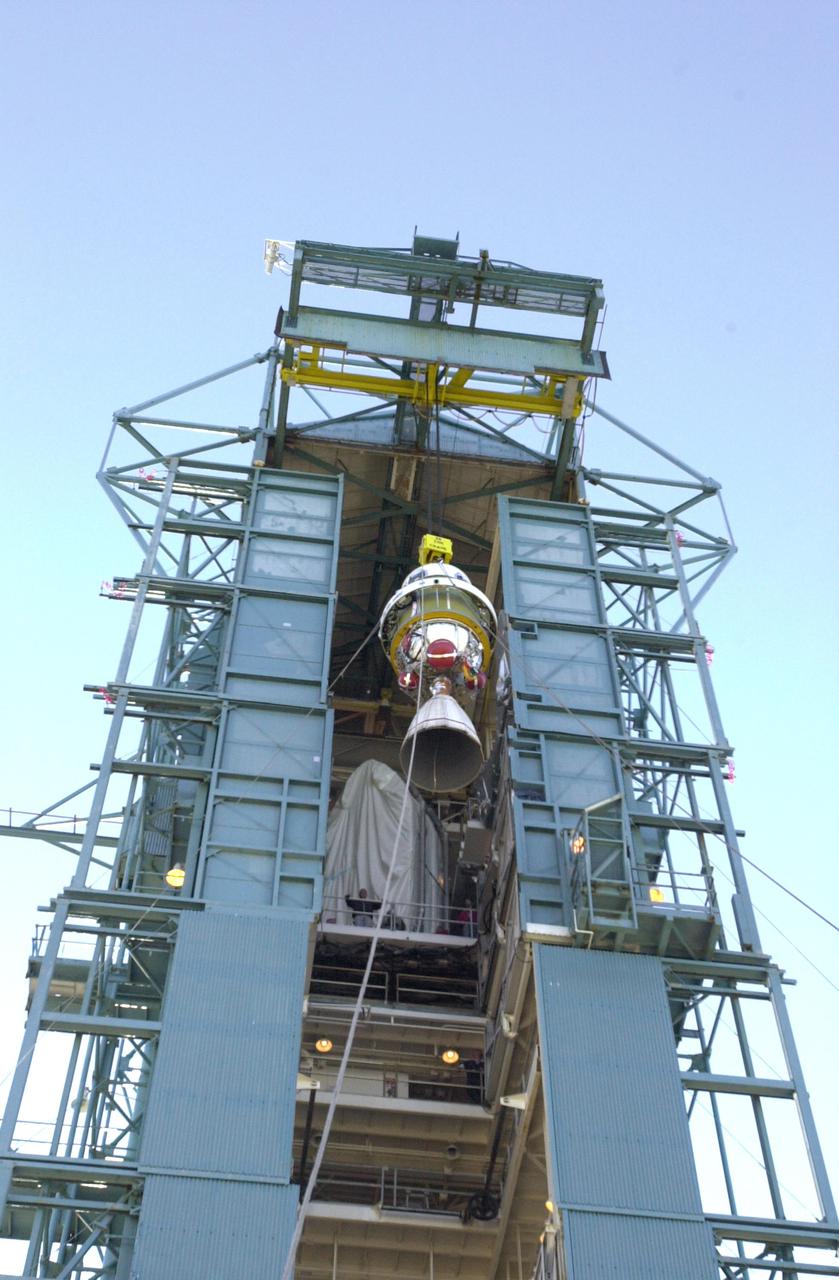
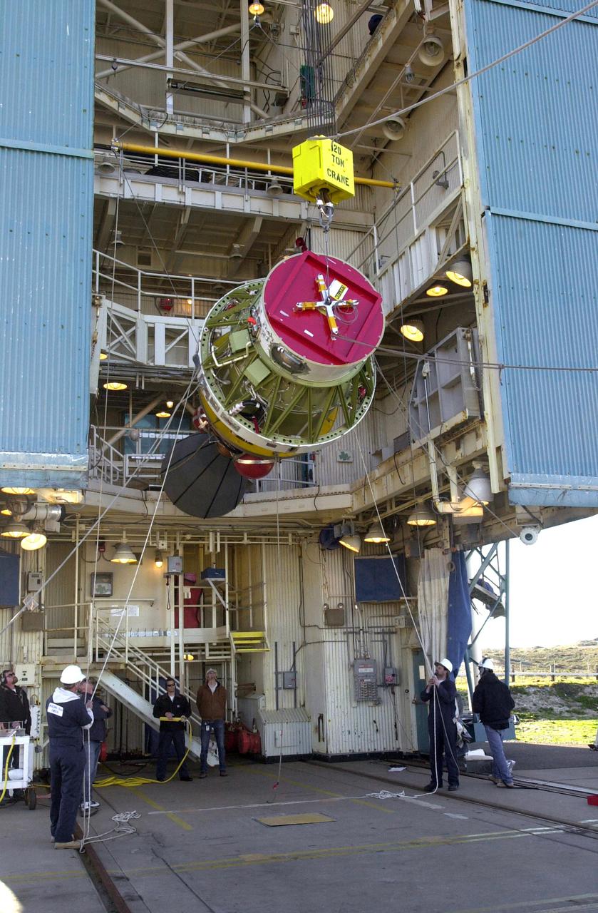
VANDENBERG AIR FORCE BASE, CALIF. - At Space Launch Complex 2 on Vandenberg Air Force Base in California, the second stage of the Boeing Delta II rocket is lifted up the service tower for mating with the first stage. The Delta II will launch the National Oceanic and Atmospheric Administration (NOAA-N) spacecraft. After launch, NOAA-N will be renamed NOAA-18 and will provide measurements of the Earth's surface and atmosphere that will be entered into NOAA’s weather forecasting models and used for other environmental studies. Each day, the satellite will send data to NOAA’s Command and Data Acquisition station computers, adding vital information to forecasting models, especially over the oceans, where conventional data is lacking. Launch of NOAA-N is scheduled for May 11, 2005.
VANDENBERG AIR FORCE BASE, CALIF. - At Space Launch Complex 2 on Vandenberg Air Force Base in California, the first stage of the Boeing Delta II rocket rests on the pad. It will be mated with the second stage. The Delta II will launch the National Oceanic and Atmospheric Administration (NOAA-N) spacecraft. After launch, NOAA-N will be renamed NOAA-18 and will provide measurements of the Earth's surface and atmosphere that will be entered into NOAA’s weather forecasting models and used for other environmental studies. Each day, the satellite will send data to NOAA’s Command and Data Acquisition station computers, adding vital information to forecasting models, especially over the oceans, where conventional data is lacking. Launch of NOAA-N is scheduled for May 11, 2005.
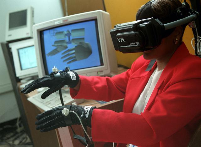
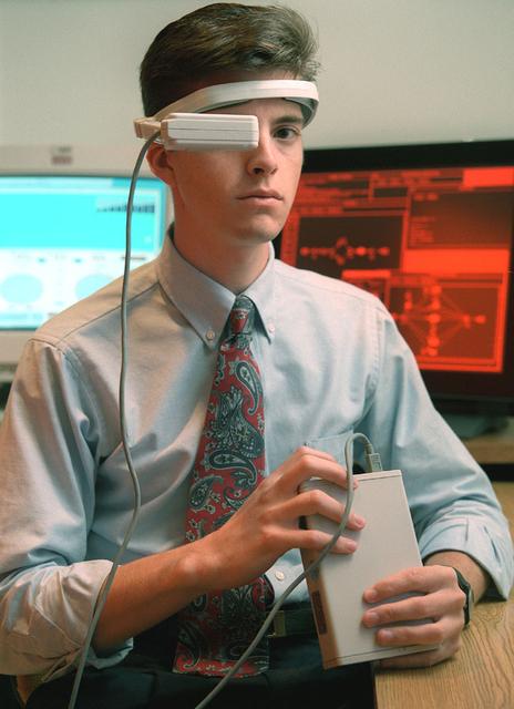
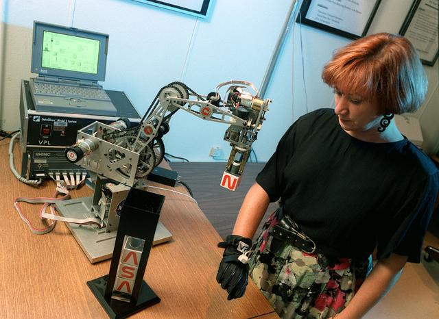
Virtual Reality (VR) can provide cost effective methods to design and evaluate components and systems for maintenance and refurbishment operations. The Marshall Space Flight Centerr (MSFC) in Huntsville, Alabama began to utilize VR for design analysis in the X-34 experimental reusable space vehicle. Analysts at MSFC's Computer Applications and Virtual Environments (CAVE) used Head Mounted Displays (HMD) (pictured), spatial trackers and gesture inputs as a means to animate or inhabit a properly sized virtual human model. These models were used in a VR scenario as a way to determine functionality of space and maintenance requirements for the virtual X-34. The primary functions of the virtual X-34 mockup was to support operations development and design analysis for engine removal, the engine compartment and the aft fuselage. This capability provided general visualization support to engineers and designers at MSFC and to the System Design Freeze Review at Orbital Sciences Corporation (OSC). The X-34 program was cancelled in 2001.
Virtual Reality (VR) can provide cost effective methods to design and evaluate components and systems for maintenance and refurbishment operations. Marshall SPace Flight Center (MSFC) is begirning to utilize VR for design analysis in the X-34 experimental reusable space vehicle. Analysts at MSFC's Computer Applications and Virtual Environments (CAVE) used Head Mounted Displays (HMD) (pictured), spatial trackers and gesture inputs as a means to animate or inhabit a properly sized virtual human model. These models are used in a VR scenario as a way to determine functionality of space and maintenance requirements for the virtual X-34. The primary functions of the virtual X-34 mockup is to support operations development and design analysis for engine removal, the engine compartment and the aft fuselage. This capability provides general visualization support to engineers and designers at MSFC and to the System Design Freeze Review at Orbital Sciences Corporation (OSC).
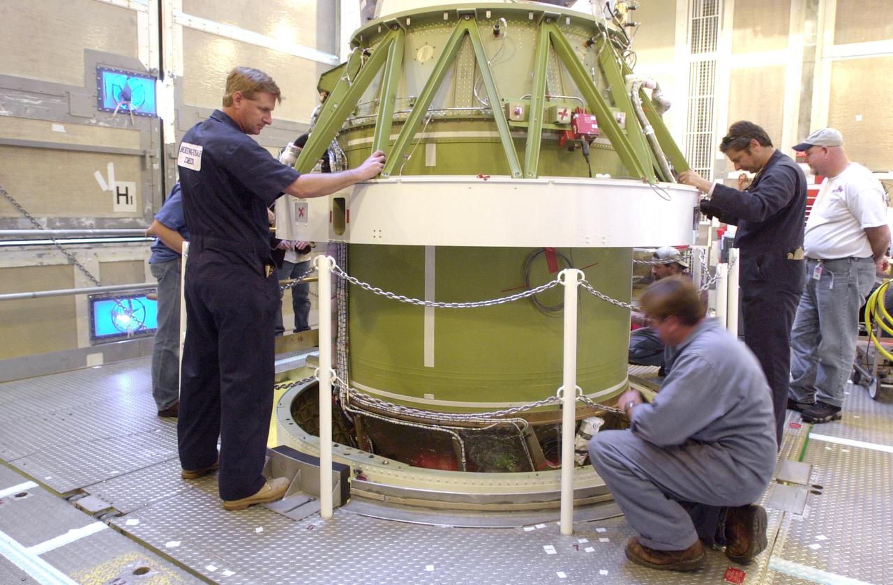
VANDENBERG AIR FORCE BASE, CALIF. - Inside the service tower at Space Launch Complex 2 on Vandenberg Air Force Base in California, Boeing workers attach the second stage to the first stage, below, of a Boeing Delta II rocket. The Delta II will launch the National Oceanic and Atmospheric Administration (NOAA-N) spacecraft. After launch, NOAA-N will be renamed NOAA-18 and will provide measurements of the Earth's surface and atmosphere that will be entered into NOAA’s weather forecasting models and used for other environmental studies. Each day, the satellite will send data to NOAA’s Command and Data Acquisition station computers, adding vital information to forecasting models, especially over the oceans, where conventional data is lacking. Launch of NOAA-N is scheduled for May 11, 2005.
Virtual Reality (VR) can provide cost effective methods to design and evaluate components and systems for maintenance and refurbishment operations. Marshall Spce Flight Center (MSFC) is begirning to utilize VR for design analysis in the X-34 experimental reusable space vehicle. Analysts at MSFC's Computer Applications and Virtual Environments (CAVE) used Head Mounted Displays (HMD) (pictured), spatial trackers and gesture inputs as a means to animate or inhabit a properly sized virtual human model. These models are used in a VR scenario as a way to determine functionality of space and maintenance requirements for the virtual X-34. The primary functions of the virtual X-34 mockup is to support operations development and design analysis for engine removal, the engine compartment and the aft fuselage. This capability provides general visualization support to engineers and designers at MSFC and to the System Design Freeze Review at Orbital Sciences Corporation (OSC).
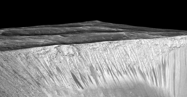
Dark narrow streaks, called "recurring slope lineae," emanate from the walls of Garni Crater on Mars, in this view constructed from observations by the High Resolution Imaging Science Experiment (HiRISE) camera on NASA's Mars Reconnaissance Orbiter. The dark streaks here are up to few hundred yards, or meters, long. They are hypothesized to be formed by flow of briny liquid water on Mars. The image was produced by first creating a 3-D computer model (a digital terrain map) of the area based on stereo information from two HiRISE observations, and then draping an image over the land-shape model. The vertical dimension is exaggerated by a factor of 1.5 compared to horizontal dimensions. The draped image is a red waveband (monochrome) product from HiRISE observation ESP_031059_1685, taken on March 12, 2013 at 11.5 degrees south latitude, 290.3 degrees east longitude. Other image products from this observation are at http://hirise.lpl.arizona.edu/ESP_031059_1685. http://photojournal.jpl.nasa.gov/catalog/PIA19917
VANDENBERG AIR FORCE BASE, CALIF. - The second stage of the Boeing Delta II rocket, in the background, arrives at Space Launch Complex 2 on Vandenberg Air Force Base in California. It will be mated with the first stage. The Delta II is the launch vehicle for the National Oceanic and Atmospheric Administration (NOAA-N) spacecraft. After launch, NOAA-N will be renamed NOAA-18 and will provide measurements of the Earth's surface and atmosphere that will be entered into NOAA’s weather forecasting models and used for other environmental studies. Each day, the satellite will send data to NOAA’s Command and Data Acquisition station computers, adding vital information to forecasting models, especially over the oceans, where conventional data is lacking. Launch of NOAA-N is scheduled for May 11, 2005.
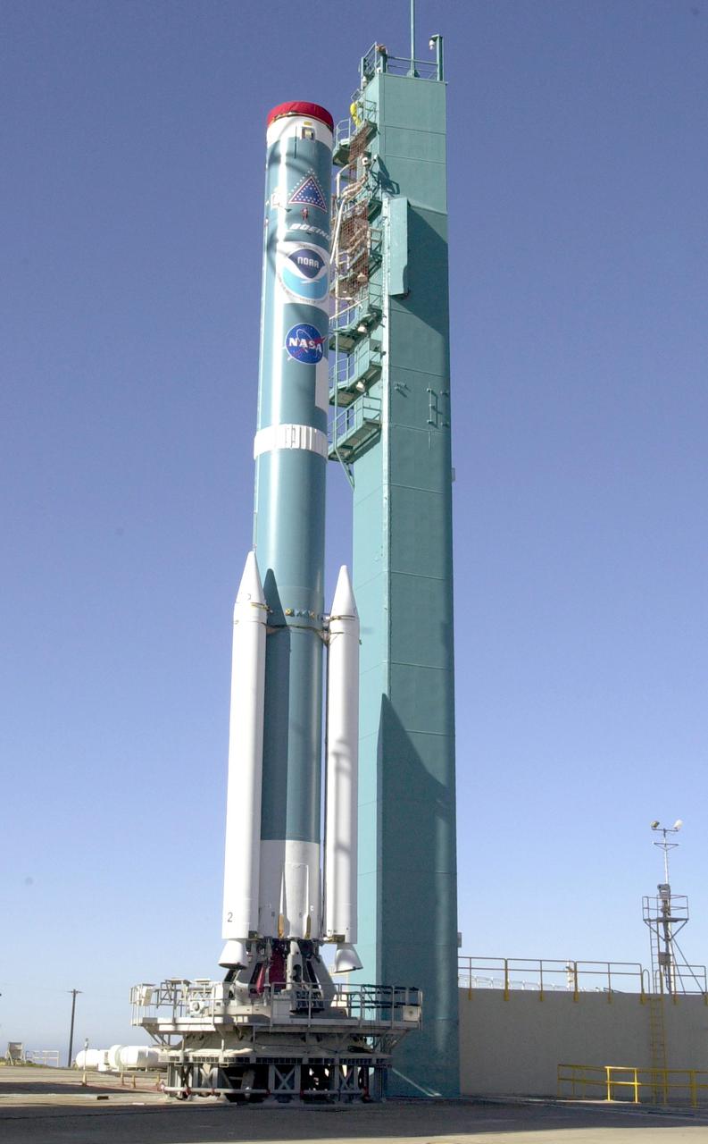
VANDENBERG AIR FORCE BASE, CALIF. - At Space Launch Complex 2 on Vandenberg Air Force Base in California, the first stage of the Boeing Delta II rocket rests on the pad. It will be mated with the second stage. The Delta II will launch the National Oceanic and Atmospheric Administration (NOAA-N) spacecraft. After launch, NOAA-N will be renamed NOAA-18 and will provide measurements of the Earth's surface and atmosphere that will be entered into NOAA’s weather forecasting models and used for other environmental studies. Each day, the satellite will send data to NOAA’s Command and Data Acquisition station computers, adding vital information to forecasting models, especially over the oceans, where conventional data is lacking. Launch of NOAA-N is scheduled for May 11, 2005.
Virtual Reality (VR) can provide cost effective methods to design and evaluate components and systems for maintenance and refurbishment operations. The Marshall Space Flight Center (MSFC) in Huntsville, Alabama began to utilize VR for design analysis in the X-34 experimental reusable space vehicle. Analysts at MSFC's Computer Applications and Virtual Environments (CAVE) used Head Mounted Displays (HMD) (pictured), spatial trackers and gesture inputs as a means to animate or inhabit a properly sized virtual human model. These models were used in a VR scenario as a way to determine functionality of space and maintenance requirements for the virtual X-34. The primary functions of the virtual X-34 mockup was to support operations development and design analysis for engine removal, the engine compartment and the aft fuselage. This capability providedgeneral visualization support to engineers and designers at MSFC and to the System Design Freeze Review at Orbital Sciences Corporation (OSC). The X-34 program was cancelled in 2001.
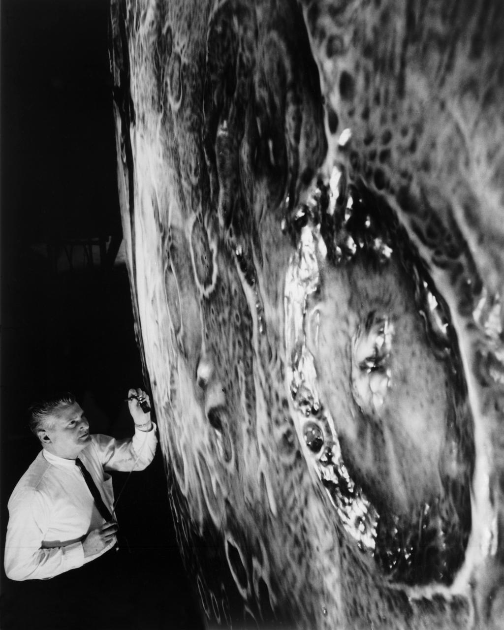
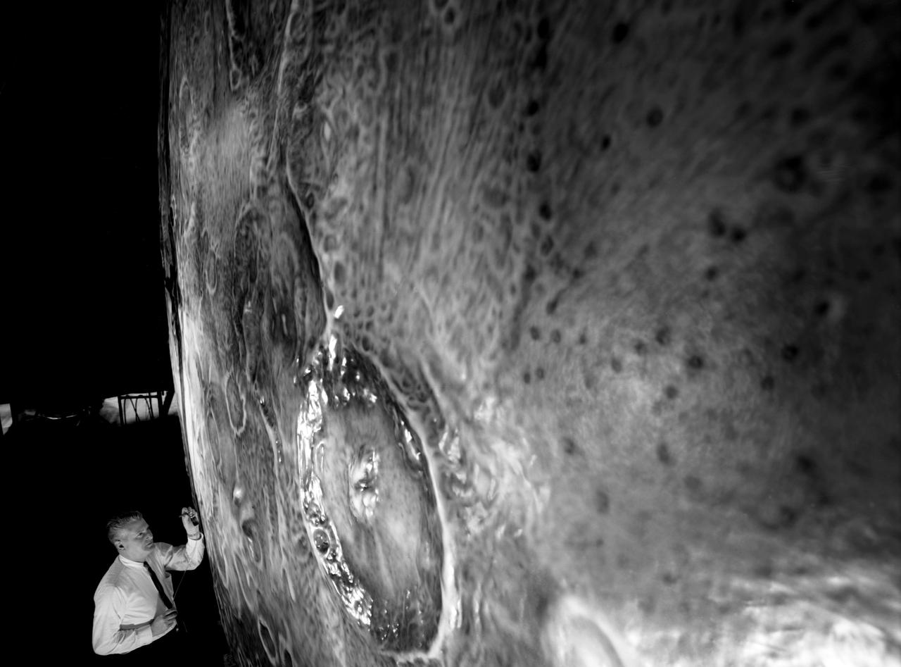
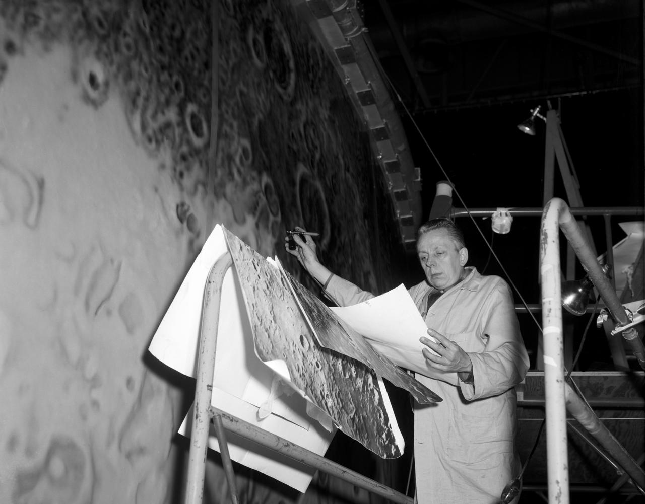
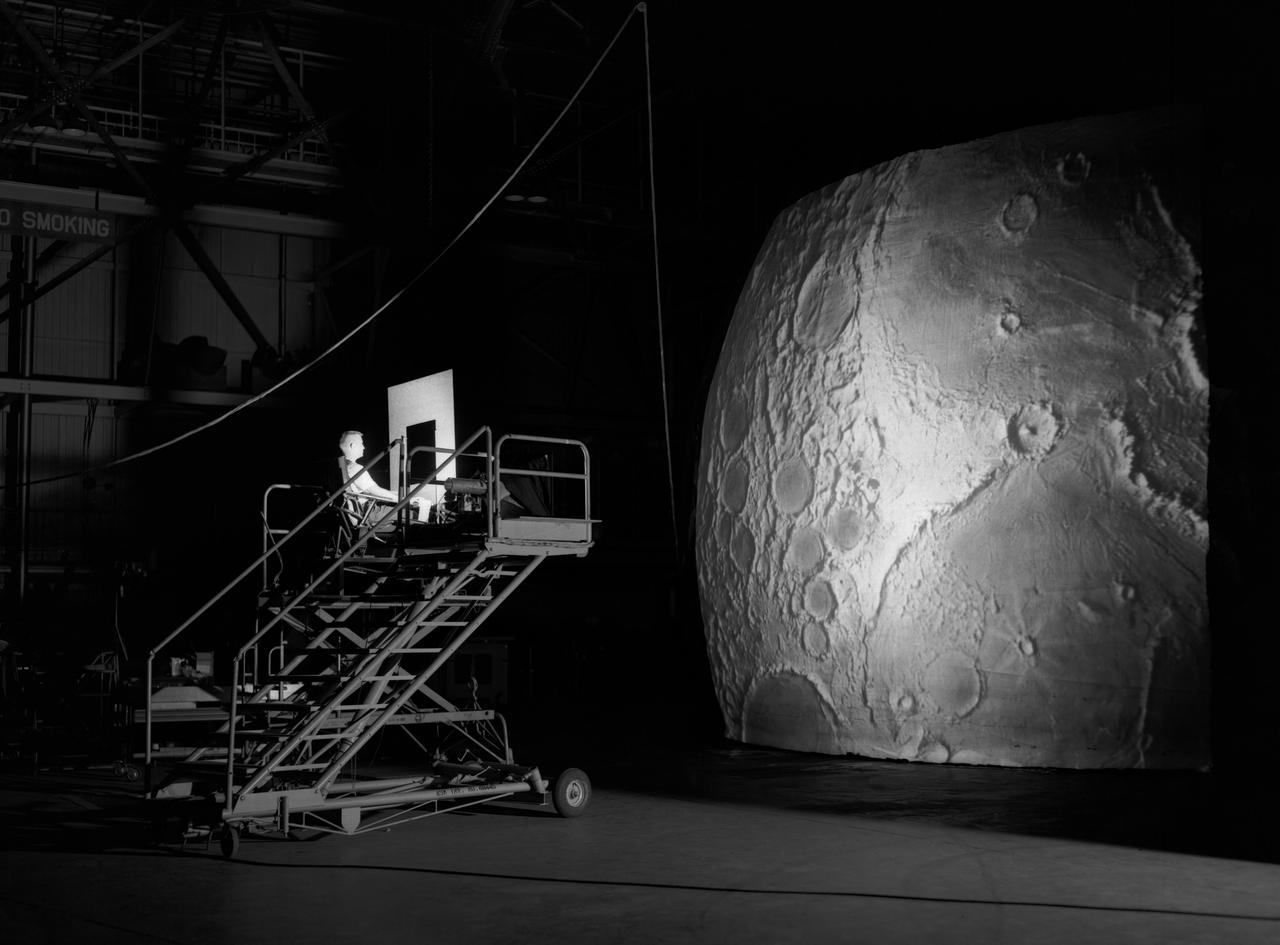
Artists used paintbrushes and airbrushes to recreate the lunar surface on each of the four models comprising the LOLA simulator. Project LOLA or Lunar Orbit and Landing Approach was a simulator built at Langley to study problems related to landing on the lunar surface. It was a complex project that cost nearly $2 million dollars. James Hansen wrote: "This simulator was designed to provide a pilot with a detailed visual encounter with the lunar surface; the machine consisted primarily of a cockpit, a closed-circuit TV system, and four large murals or scale models representing portions of the lunar surface as seen from various altitudes. The pilot in the cockpit moved along a track past these murals which would accustom him to the visual cues for controlling a spacecraft in the vicinity of the moon. Unfortunately, such a simulation--although great fun and quite aesthetic--was not helpful because flight in lunar orbit posed no special problems other than the rendezvous with the LEM, which the device did not simulate. Not long after the end of Apollo, the expensive machine was dismantled." (p. 379) Ellis J. White further described LOLA in his paper "Discussion of Three Typical Langley Research Center Simulation Programs," "Model 1 is a 20-foot-diameter sphere mounted on a rotating base and is scaled 1 in. = 9 miles. Models 2,3, and 4 are approximately 15x40 feet scaled sections of model 1. Model 4 is a scaled-up section of the Crater Alphonsus and the scale is 1 in. = 200 feet. All models are in full relief except the sphere." -- Published in James R. Hansen, Spaceflight Revolution: NASA Langley Research Center From Sputnik to Apollo, (Washington: NASA, 1995), p. 379; From Ellis J. White, "Discussion of Three Typical Langley Research Center Simulation Programs," Paper presented at the Eastern Simulation Council (EAI's Princeton Computation Center), Princeton, NJ, October 20, 1966.
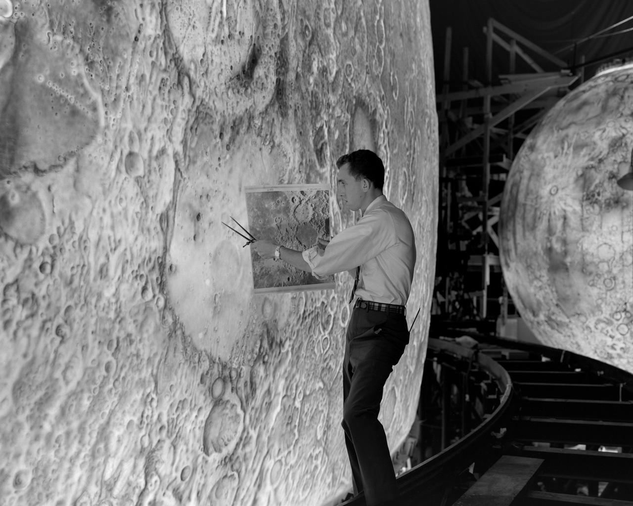
Artists used paintbrushes and airbrushes to recreate the lunar surface on each of the four models comprising the LOLA simulator. Project LOLA or Lunar Orbit and Landing Approach was a simulator built at Langley to study problems related to landing on the lunar surface. It was a complex project that cost nearly 2 million dollars. James Hansen wrote: This simulator was designed to provide a pilot with a detailed visual encounter with the lunar surface the machine consisted primarily of a cockpit, a closed-circuit TV system, and four large murals or scale models representing portions of the lunar surface as seen from various altitudes. The pilot in the cockpit moved along a track past these murals which would accustom him to the visual cues for controlling a spacecraft in the vicinity of the moon. Unfortunately, such a simulation--although great fun and quite aesthetic--was not helpful because flight in lunar orbit posed no special problems other than the rendezvous with the LEM, which the device did not simulate. Not long after the end of Apollo, the expensive machine was dismantled. (p. 379) Ellis J. White described the simulator as follows: Model 1 is a 20-foot-diameter sphere mounted on a rotating base and is scaled 1 in. 9 miles. Models 2,3, and 4 are approximately 15x40 feet scaled sections of model 1. Model 4 is a scaled-up section of the Crater Alphonsus and the scale is 1 in. 200 feet. All models are in full relief except the sphere. -- Published in James R. Hansen, Spaceflight Revolution: NASA Langley Research Center From Sputnik to Apollo, (Washington: NASA, 1995), p. 379 Ellis J. White, Discussion of Three Typical Langley Research Center Simulation Programs, Paper presented at the Eastern Simulation Council (EAI s Princeton Computation Center), Princeton, NJ, October 20, 1966.
Artists used paintbrushes and airbrushes to recreate the lunar surface on each of the four models comprising the LOLA simulator. Project LOLA or Lunar Orbit and Landing Approach was a simulator built at Langley to study problems related to landing on the lunar surface. It was a complex project that cost nearly $2 million dollars. James Hansen wrote: "This simulator was designed to provide a pilot with a detailed visual encounter with the lunar surface; the machine consisted primarily of a cockpit, a closed-circuit TV system, and four large murals or scale models representing portions of the lunar surface as seen from various altitudes. The pilot in the cockpit moved along a track past these murals which would accustom him to the visual cues for controlling a spacecraft in the vicinity of the moon. Unfortunately, such a simulation--although great fun and quite aesthetic--was not helpful because flight in lunar orbit posed no special problems other than the rendezvous with the LEM, which the device did not simulate. Not long after the end of Apollo, the expensive machine was dismantled." (p. 379) Ellis J. White further described LOLA in his paper "Discussion of Three Typical Langley Research Center Simulation Programs," "Model 1 is a 20-foot-diameter sphere mounted on a rotating base and is scaled 1 in. = 9 miles. Models 2,3, and 4 are approximately 15x40 feet scaled sections of model 1. Model 4 is a scaled-up section of the Crater Alphonsus and the scale is 1 in. = 200 feet. All models are in full relief except the sphere." -- Published in James R. Hansen, Spaceflight Revolution: NASA Langley Research Center From Sputnik to Apollo, (Washington: NASA, 1995), p. 379; Ellis J. White, "Discussion of Three Typical Langley Research Center Simulation Programs," Paper presented at the Eastern Simulation Council (EAI's Princeton Computation Center), Princeton, NJ, October 20, 1966.
Artists used paintbrushes and airbrushes to recreate the lunar surface on each of the four models comprising the LOLA simulator. Project LOLA or Lunar Orbit and Landing Approach was a simulator built at Langley to study problems related to landing on the lunar surface. It was a complex project that cost nearly $2 million dollars. James Hansen wrote: "This simulator was designed to provide a pilot with a detailed visual encounter with the lunar surface; the machine consisted primarily of a cockpit, a closed-circuit TV system, and four large murals or scale models representing portions of the lunar surface as seen from various altitudes. The pilot in the cockpit moved along a track past these murals which would accustom him to the visual cues for controlling a spacecraft in the vicinity of the moon. Unfortunately, such a simulation--although great fun and quite aesthetic--was not helpful because flight in lunar orbit posed no special problems other than the rendezvous with the LEM, which the device did not simulate. Not long after the end of Apollo, the expensive machine was dismantled." (p. 379) Ellis J. White further described LOLA in his paper "Discussion of Three Typical Langley Research Center Simulation Programs," "Model 1 is a 20-foot-diameter sphere mounted on a rotating base and is scaled 1 in. = 9 miles. Models 2,3, and 4 are approximately 15x40 feet scaled sections of model 1. Model 4 is a scaled-up section of the Crater Alphonsus and the scale is 1 in. = 200 feet. All models are in full relief except the sphere." -- Published in James R. Hansen, Spaceflight Revolution, NASA SP-4308, p. 379; Ellis J. White, "Discussion of Three Typical Langley Research Center Simulation Programs," Paper presented at the Eastern Simulation Council (EAI's Princeton Computation Center), Princeton, NJ, October 20, 1966.
jsc2023e010183 (2/28/2023) --- The High school students United with NASA to Create Hardware (HUNCH) Ball Clamp Monopod (HUNCH Ball Clamp Monopod) investigation aims to test a temporary but stable platform for holding cameras, making camera operations easier and faster for the International Space Station crew. This hardware was designed and developed by HUNCH students using engineering design processes. They produced elements such as Computer Aided Design (CAD) drawings, CAD study models, and 3D printed engineering evaluation units on parts such as this insert that allow the seat track clamp to be positioned. Image courtesy of HUNCH.
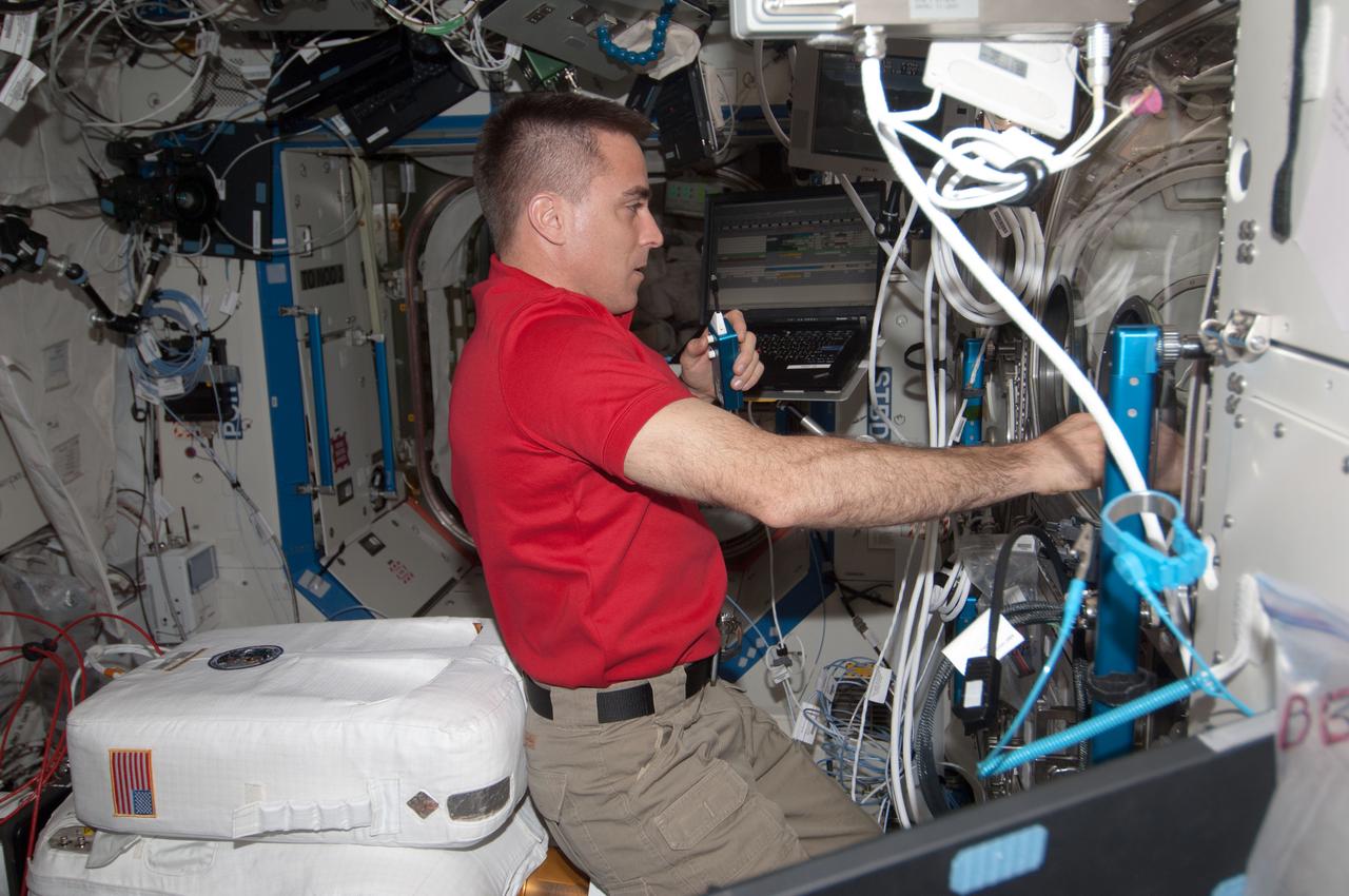
ISS035-E-16429 (9 April 2013) --- Astronaut Chris Cassidy, Expedition 35 flight engineer, conducts a session of the Burning and Suppression of Solids (BASS) experiment located in the U.S. lab Destiny onboard the Earth-orbiting International Space Station. Cassidy over a period of several days, has conducted several "runs" of the experiment, which examines the burning and extinction characteristics of a wide variety of fuel samples in microgravity and will guide strategies for extinguishing fires in microgravity. BASS results contribute to the combustion computational models used in the design of fire detection and suppression systems in microgravity and on Earth.
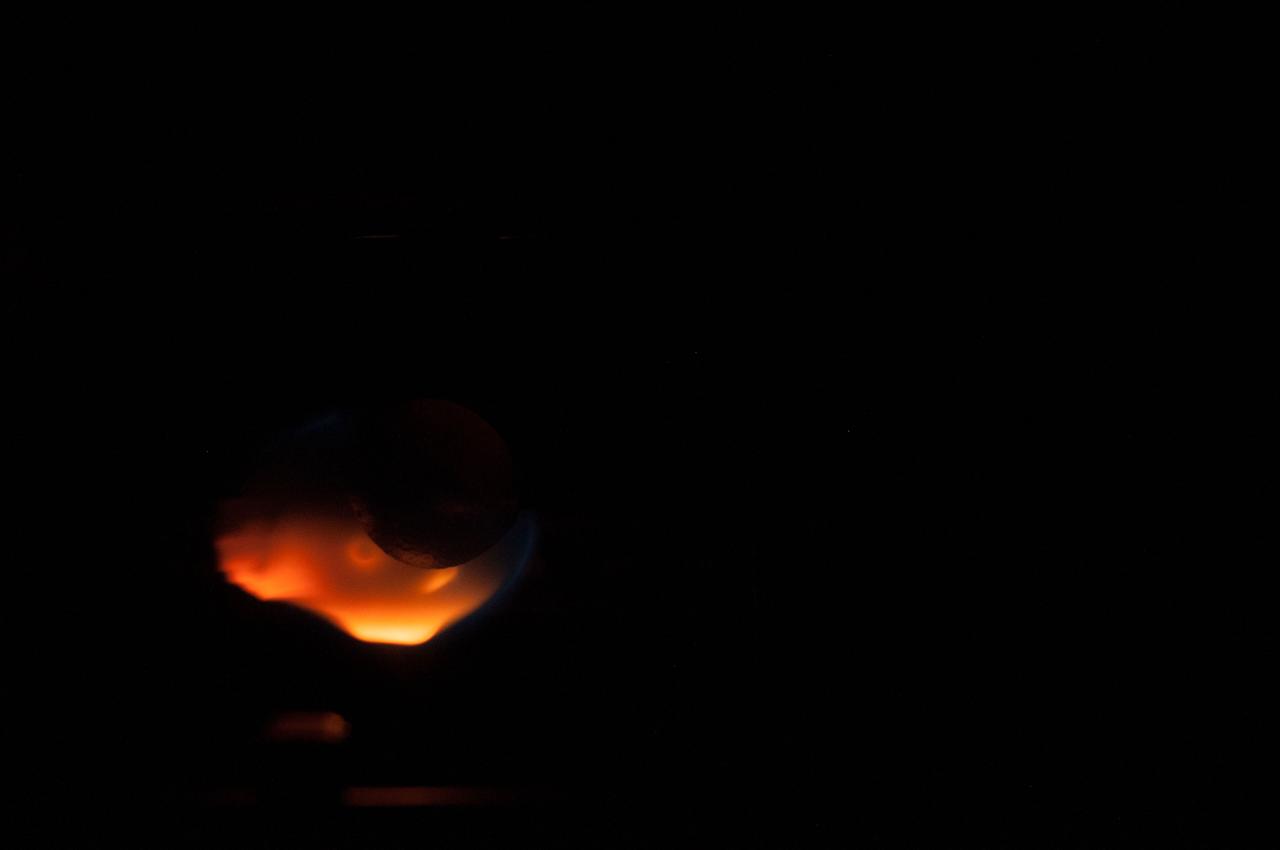
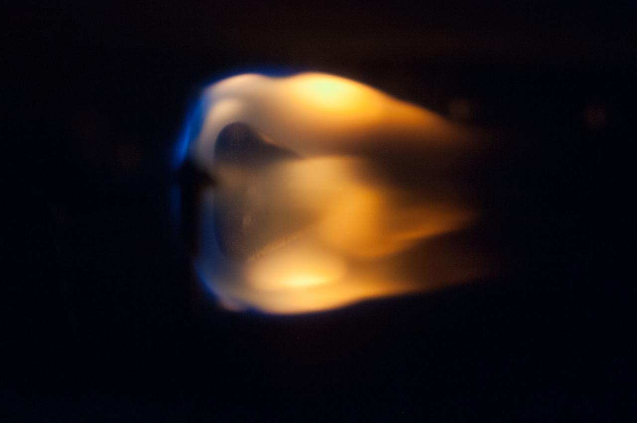
ISS035-E-015679 (10 April 2013) --- This is one of a series of close-up images photographed during a run of the Burning and Suppression of Solids (BASS) experiment onboard the Earth-orbiting International Space Station. Following a series of preparations, NASA astronaut Chris Cassidy (out of frame) conducted a series of runs of the experiment, which examines the burning and extinction characteristics of a wide variety of fuel samples in microgravity. The experiment is planned for guiding strategies for extinguishing fires in microgravity. BASS results contribute to the combustion computational models used in the design of fire detection and suppression systems in microgravity and on Earth.

ISS035-E-015930 (10 April 2013) --- This is one of a series of close-up images photographed during a run of the Burning and Suppression of Solids (BASS) experiment onboard the Earth-orbiting International Space Station. Following a series of preparations, NASA astronaut Chris Cassidy (out of frame) conducted several runs of the experiment, which examines the burning and extinction characteristics of a wide variety of fuel samples in microgravity. The experiment is planned for guiding strategies for extinguishing fires in microgravity. BASS results contribute to the combustion computational models used in the design of fire detection and suppression systems in microgravity and on Earth.

ISS035-E-015900 (10 April 2013) --- This is one of a series of close-up images photographed during a run of the Burning and Suppression of Solids (BASS) experiment onboard the Earth-orbiting International Space Station. Following a series of preparations, NASA astronaut Chris Cassidy (out of frame) conducted several runs of the experiment, which examines the burning and extinction characteristics of a wide variety of fuel samples in microgravity. The experiment is planned for guiding strategies for extinguishing fires in microgravity. BASS results contribute to the combustion computational models used in the design of fire detection and suppression systems in microgravity and on Earth.
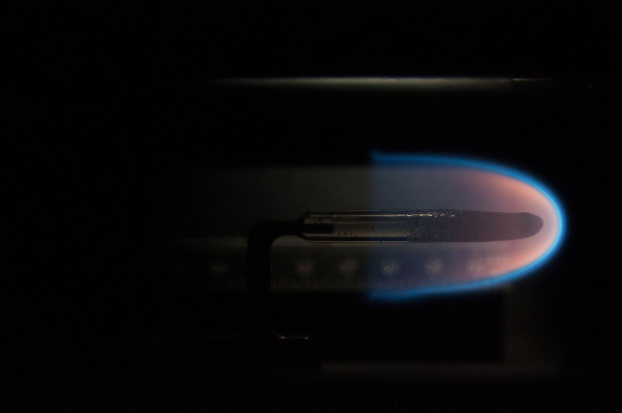
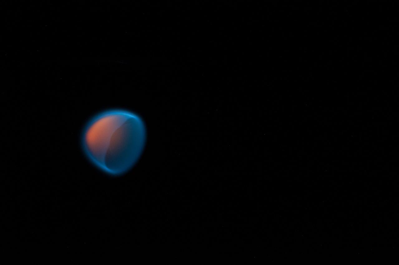
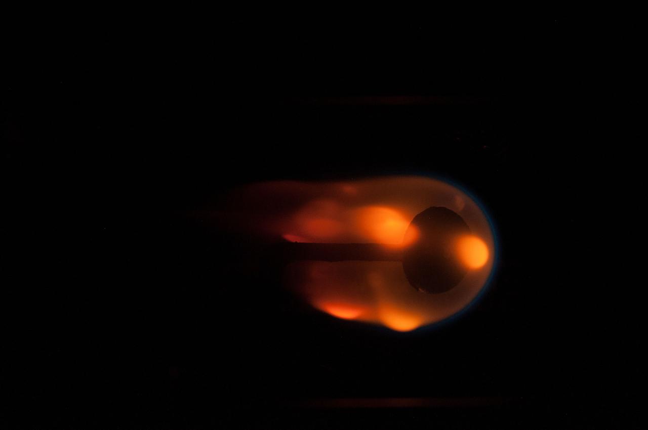
Image taken on card 15 during BASS-II flame test session with reduced O2 partial pressure. Session conducted on GMT 214. The Burning and Suppression of Solids - II (BASS-II) investigation examines the burning and extinction characteristics of a wide variety of fuel samples in microgravity. The BASS-II experiment will guide strategies for materials flammability screening for use in spacecraft as well as provide valuable data on solid fuel burning behavior in microgravity. BASS-II results contribute to the combustion computational models used in the design of fire detection and suppression systems in microgravity and on Earth.
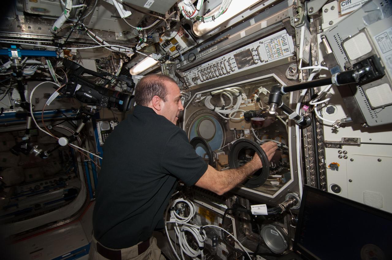
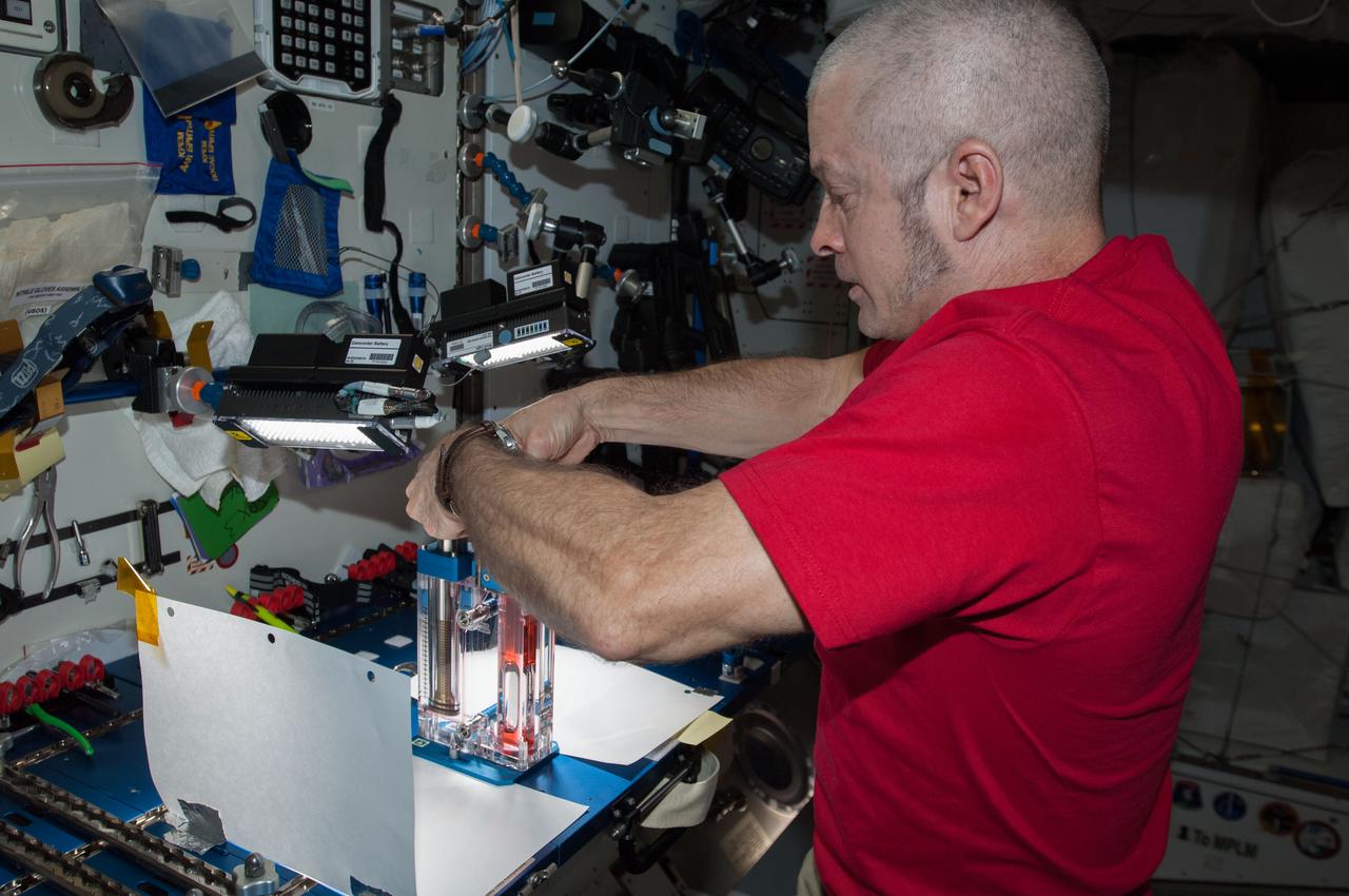
ISS039-E-005726 (27 March 2014) --- Expedition 39 Flight Engineer Rick Mastracchio performs inflight maintenance on an experiment called Burning and Suppression of Solids (BASS)-II. The investigation examines the burning and extinction characteristics of a wide variety of fuel samples in microgravity. The BASS-II experiment will guide strategies for materials flammability screening for use in spacecraft as well as provide valuable data on solid fuel burning behavior in microgravity. BASS-II results contribute to the combustion computational models used in the design of fire detection and suppression systems in microgravity and on Earth.
ISS035-E-015827 (10 April 2013) --- This is one of a series of close-up images photographed during a run of the Burning and Suppression of Solids (BASS) experiment onboard the Earth-orbiting International Space Station. Following a series of preparations, NASA astronaut Chris Cassidy (out of frame) conducted a series of runs of the experiment, which examines the burning and extinction characteristics of a wide variety of fuel samples in microgravity. The experiment is planned for guiding strategies for extinguishing fires in microgravity. BASS results contribute to the combustion computational models used in the design of fire detection and suppression systems in microgravity and on Earth.
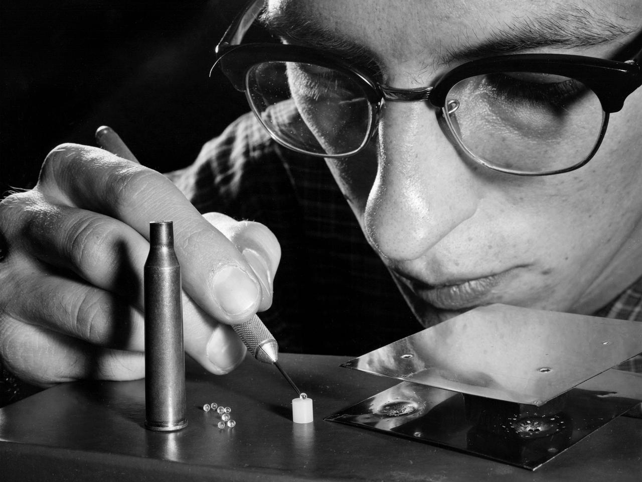
A researcher at the NASA Lewis Research Center manipulates cartridge pellets and a strain gauge target as part of a study on the impact of micrometeorites striking space vehicles. Early in the space program NASA researchers were concerned that small micrometeorites would penetrate spacecraft, injure engines, or damage solar arrays. In response, researchers worked to develop stronger materials to withstand meteorite strikes and screens to block the objects. NASA launched a series of experimental spacecraft into orbit with foil shields that were used to determine the number of meteorite strikes. By the early 1960s the experiments and computer modelling efforts revealed that the micrometeoroid threat was lower than previously anticipated.
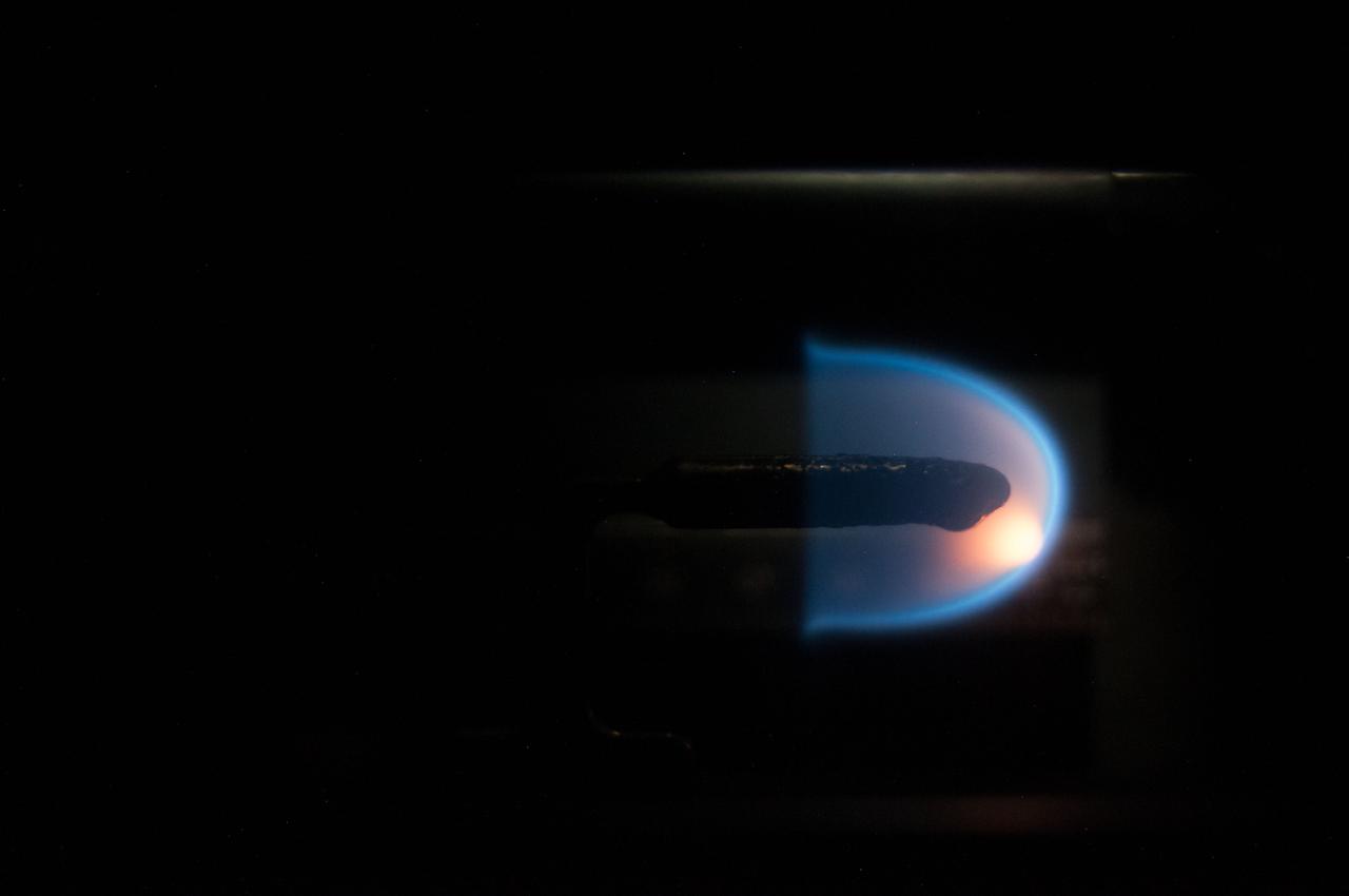
Image taken on card 8 during BASS-II flame test session with reduced O2 partial pressure. Session conducted on GMT 213. The Burning and Suppression of Solids - II (BASS-II) investigation examines the burning and extinction characteristics of a wide variety of fuel samples in microgravity. The BASS-II experiment will guide strategies for materials flammability screening for use in spacecraft as well as provide valuable data on solid fuel burning behavior in microgravity. BASS-II results contribute to the combustion computational models used in the design of fire detection and suppression systems in microgravity and on Earth.
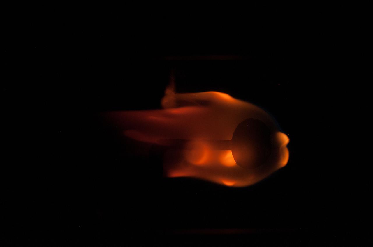
ISS040-E-023287 (27 June 2014) --- This is a close-up image photographed during a run of the Burning and Suppression of Solids (BASS) experiment onboard the Earth-orbiting International Space Station. Following a series of preparations, NASA astronaut Reid Wiseman (out of frame), Expedition 40 flight engineer, conducted runs of the experiment, which examines the burning and extinction characteristics of a wide variety of fuel samples in microgravity. The experiment is planned for guiding strategies for extinguishing fires in microgravity. BASS results contribute to the combustion computational models used in the design of fire detection and suppression systems in microgravity and on Earth.
ISS035-E-014987 (6 April 2013) --- This is a close-up image photographed during a run of the Burning and Suppression of Solids (BASS) experiment onboard the Earth-orbiting International Space Station. Following a series of preparations, NASA astronaut Chris Cassidy (out of frame) conducted runs of the experiment, which examines the burning and extinction characteristics of a wide variety of fuel samples in microgravity. The experiment is planned for guiding strategies for extinguishing fires in microgravity. BASS results contribute to the combustion computational models used in the design of fire detection and suppression systems in microgravity and on Earth.
ISS035-E-014971 (6 April 2013) --- This is a close-up image photographed during a run of the Burning and Suppression of Solids (BASS) experiment onboard the Earth-orbiting International Space Station. Following a series of preparations, NASA astronaut Chris Cassidy (out of frame) conducted runs of the experiment, which examines the burning and extinction characteristics of a wide variety of fuel samples in microgravity. The experiment is planned for guiding strategies for extinguishing fires in microgravity. BASS results contribute to the combustion computational models used in the design of fire detection and suppression systems in microgravity and on Earth.
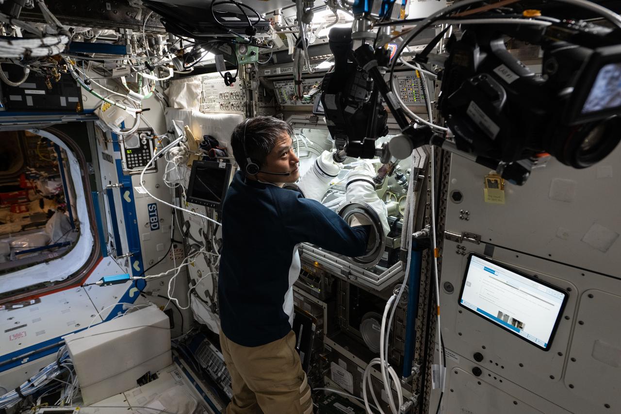
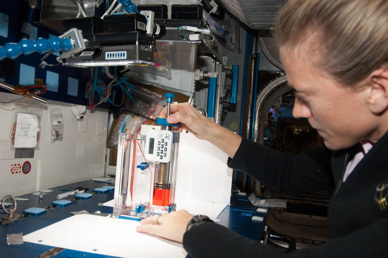
iss073e0177064 (6/11/2025) --- Scientists can study protein solutions without interference from container walls and gravity driven forces present on Earth using the space station’s Ring Sheared Drop module. The device pins a drop of liquid between two rings and holds it in place with surface tension. JAXA astronaut Takuya Onishi sets up for Ring Sheared Drop-IBP-2, a study of the behavior of protein fluids in microgravity. The investigation uses the module to test computer models to predict fluid behavior that could lead to improved processes for manufacturing pharmaceuticals, 3D printing, food processing, and microelectronics.
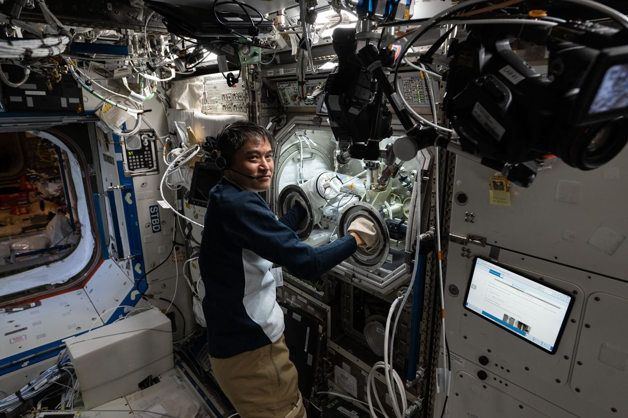
iss073e0177065 (6/11/2025) --- Scientists can study protein solutions without interference from container walls and gravity driven forces present on Earth using the space station’s Ring Sheared Drop module. The device pins a drop of liquid between two rings and holds it in place with surface tension. JAXA (Japan Aerospace Exploration Agency) astronaut and Expedition 73 Commander Takuya Onishi sets up for Ring Sheared Drop-IBP-2, a study of the behavior of protein fluids in microgravity. The investigation uses the module to test computer models to predict fluid behavior that could lead to improved processes for manufacturing pharmaceuticals, 3D printing, food processing, and microelectronics.
ISS035-E-015952 (10 April 2013) --- This is one of a series of close-up images photographed during a run of the Burning and Suppression of Solids (BASS) experiment onboard the Earth-orbiting International Space Station. Following a series of preparations, on April 5 NASA astronaut Chris Cassidy (out of frame) conducted several runs of the experiment, which examines the burning and extinction characteristics of a wide variety of fuel samples in microgravity. The experiment is planned for guiding strategies for extinguishing fires in microgravity. BASS results contribute to the combustion computational models used in the design of fire detection and suppression systems in microgravity and on Earth.

ISS040-E-073120 (23 July 2014) --- This is a close-up image photographed during a run of the Burning and Suppression of Solids (BASS) experiment onboard the Earth-orbiting International Space Station. Following a series of preparations, NASA astronaut Reid Wiseman (out of frame), Expedition 40 flight engineer, conducted runs of the experiment, which examines the burning and extinction characteristics of a wide variety of fuel samples in microgravity. The experiment is planned for guiding strategies for extinguishing fires in microgravity. BASS results contribute to the combustion computational models used in the design of fire detection and suppression systems in microgravity and on Earth.
![For me, I picked up an interest for engineering through drawing. When I was young, I was really big into art. Like most science-drawn younger kids, I would draw Pokémon, I would draw Dragon Ball Z, things like that. I guess my passion for art and drawing helped me to get into CAD (Computer Aided Design) modeling — things like 3D modeling and 3D printing. And with CAD modeling, you need to learn how to figure out the dimensions of things, what material they’re made out of, xyz. So that got me deeper into engineering. There’s definitely an artistic component to science. You can just look at James Webb [Space Telescope]. It looks artistic. If you look at the beveled mirrors, or how the bat wings on the side fold out, I would argue that that is artistic in a sense. But it also matches perfectly with its scientific functions. So not only does it need to fit into the rocket, but it also needs these beveled mirrors to reflect light at a specific angle. So, I think art and science blend pretty well. Kenneth Harris II, lead database engineer for the Joint Polar Satellite System (JPSS) J2 Satellite Mission at NASA’s Goddard Space Flight Center, Friday, Feb. 21, 2020, Greenbelt, Md. Photo Credit: (NASA/Joel Kowsky)](https://images-assets.nasa.gov/image/NHQ202002210002/NHQ202002210002~medium.jpg)
For me, I picked up an interest for engineering through drawing. When I was young, I was really big into art. Like most science-drawn younger kids, I would draw Pokémon, I would draw Dragon Ball Z, things like that. I guess my passion for art and drawing helped me to get into CAD (Computer Aided Design) modeling — things like 3D modeling and 3D printing. And with CAD modeling, you need to learn how to figure out the dimensions of things, what material they’re made out of, xyz. So that got me deeper into engineering. There’s definitely an artistic component to science. You can just look at James Webb [Space Telescope]. It looks artistic. If you look at the beveled mirrors, or how the bat wings on the side fold out, I would argue that that is artistic in a sense. But it also matches perfectly with its scientific functions. So not only does it need to fit into the rocket, but it also needs these beveled mirrors to reflect light at a specific angle. So, I think art and science blend pretty well. Kenneth Harris II, lead database engineer for the Joint Polar Satellite System (JPSS) J2 Satellite Mission at NASA’s Goddard Space Flight Center, Friday, Feb. 21, 2020, Greenbelt, Md. Photo Credit: (NASA/Joel Kowsky)
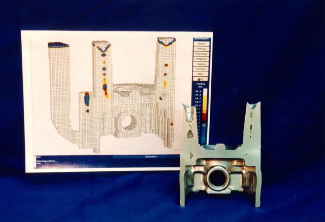
This is a computer generated model of a ground based casting. The objective of the therophysical properties program is to measure thermal physical properties of commercial casting alloys for use in computer programs that predict soldification behavior. This could reduce trial and error in casting design and promote less scrap, sounder castings, and less weight. In order for the computer models to reliably simulate the details of industrial alloy solidification, the input thermophysical property data must be absolutely reliable. Recently Auburn University and TPRL Inc. formed a teaming relationship to establish reliable measurement techniques for the most critical properties of commercially important alloys: transformation temperatures, thermal conductivity, electrical conductivity, specific heat, latent heat, density, solid fraction evolution, surface tension, and viscosity. A new initiative with the American Foundrymens Society has been started to measure the thermophysical properties of commercial ferrous and non-ferrous casting alloys and make the thermophysical property data widely available. Development of casting processes for the new gamma titanium aluminide alloys as well as existing titanium alloys will remain a trial-and-error procedure until accurate thermophysical properties can be obtained. These molten alloys react with their containers on earth and change their composition - invalidating the measurements even while the data are being acquired in terrestrial laboratories. However, measurements on the molten alloys can be accomplished in space using freely floating droplets which are completely untouched by any container. These data are expected to be exceptionally precise because of the absence of impurity contamination and buoyancy convection effects. Although long duration orbital experiments will be required for the large scale industrial alloy measurement program that results from this research, short duration experiments on NASA's KC-135 low-g aircraft are already providing preliminary data and experience.
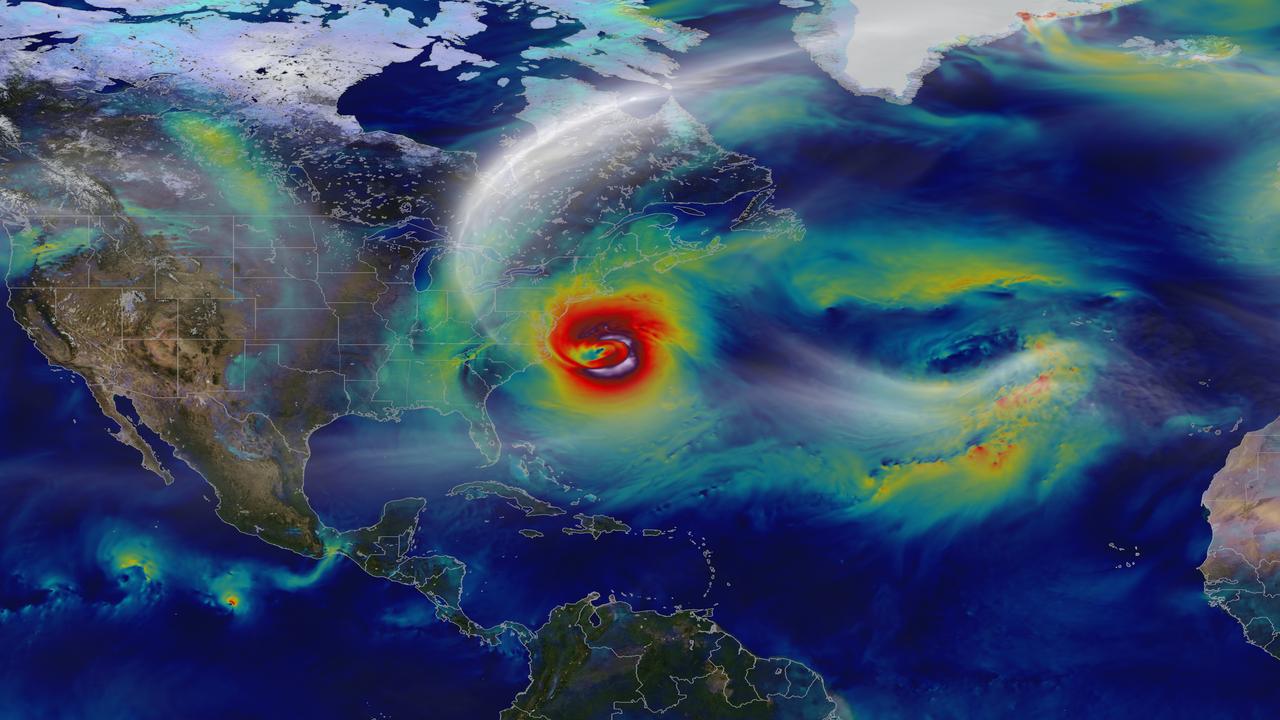
Oct. 29, 2012 – A day before landfall, Sandy intensified into a Category 2 superstorm nearly 1,000 miles wide. Credit: NASA's Goddard Space Flight Center and NASA Center for Climate Simulation Video and images courtesy of NASA/GSFC/William Putman -- A NASA computer model simulates the astonishing track and forceful winds of Hurricane Sandy. Hurricane Sandy pummeled the East Coast late in 2012’s Atlantic hurricane season, causing 159 deaths and $70 billion in damages. Days before landfall, forecasts of its trajectory were still being made. Some computer models showed that a trough in the jet stream would kick the monster storm away from land and out to sea. Among the earliest to predict its true course was NASA’s GEOS-5 global atmosphere model. The model works by dividing Earth’s atmosphere into a virtual grid of stacked boxes. A supercomputer then solves mathematical equations inside each box to create a weather forecast predicting Sandy’s structure, path and other traits. The NASA model not only produced an accurate track of Sandy, but also captured fine-scale details of the storm’s changing intensity and winds. Watch the video to see it for yourself. For more information, please visit: <a href="http://gmao.gsfc.nasa.gov/research/atmosphericassim/tracking_hurricanes/" rel="nofollow">gmao.gsfc.nasa.gov/research/atmosphericassim/tracking_hur...</a> <b><a href="http://www.nasa.gov/audience/formedia/features/MP_Photo_Guidelines.html" rel="nofollow">NASA image use policy.</a></b> <b><a href="http://www.nasa.gov/centers/goddard/home/index.html" rel="nofollow">NASA Goddard Space Flight Center</a></b> enables NASA’s mission through four scientific endeavors: Earth Science, Heliophysics, Solar System Exploration, and Astrophysics. Goddard plays a leading role in NASA’s accomplishments by contributing compelling scientific knowledge to advance the Agency’s mission. <b>Follow us on <a href="http://twitter.com/NASA_GoddardPix" rel="nofollow">Twitter</a></b> <b>Like us on <a href="http://www.facebook.com/pages/Greenbelt-MD/NASA-Goddard/395013845897?ref=tsd" rel="nofollow">Facebook</a></b> <b>Find us on <a href="http://instagram.com/nasagoddard?vm=grid" rel="nofollow">Instagram</a></b>
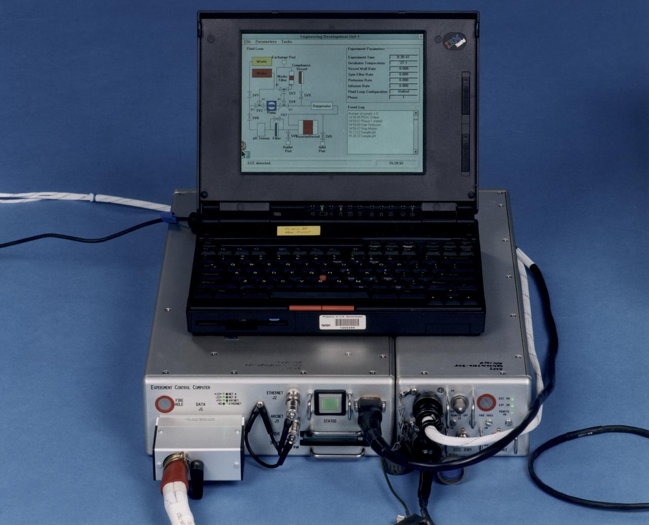
Laptop computer sits atop the Experiment Control Computer for a NASA Bioreactor. The flight crew can change operating conditions in the Bioreactor by using the graphical interface on the laptop. The NASA Bioreactor provides a low turbulence culture environment which promotes the formation of large, three-dimensional cell clusters. The Bioreactor is rotated to provide gentle mixing of fresh and spent nutrient without inducing shear forces that would damage the cells. Due to their high level of cellular organization and specialization, samples constructed in the bioreactor more closely resemble the original tumor or tissue found in the body. The work is sponsored by NASA's Office of Biological and Physical Research. The bioreactor is managed by the Biotechnology Cell Science Program at NASA's Johnson Space Center (JSC). NASA-sponsored bioreactor research has been instrumental in helping scientists to better understand normal and cancerous tissue development. In cooperation with the medical community, the bioreactor design is being used to prepare better models of human colon, prostate, breast and ovarian tumors. Cartilage, bone marrow, heart muscle, skeletal muscle, pancreatic islet cells, liver and kidney are just a few of the normal tissues being cultured in rotating bioreactors by investigators.

During a Crew Equipment Interface Test, STS-103 Commander Curtis L. Brown Jr. (left) and Pilot Scott J. Kelly look at a replacement computer for the Hubble Space Telescope. The payload hardware is in the Payload Hazardous Servicing Facility. Other members of the crew are Mission Specialists Steven L. Smith, C. Michael Foale (Ph.D.), John M. Grunsfeld (Ph.D.), Claude Nicollier of Switzerland, and Jean-François Clervoy of France. Nicollier and Clervoy are with the European Space Agency. Mission STS-103 is a "call-up" due to the need to replace portions of the pointing system, the gyros, which have begun to fail on the Hubble Space Telescope. Although Hubble is operating normally and conducting its scientific observations, only three of its six gyroscopes are working properly. The gyroscopes allow the telescope to point at stars, galaxies and planets. The STS-103 crew will not only replace gyroscopes, it will also replace a Fine Guidance Sensor and an older computer with the new enhanced model, an older data tape recorder with a solid state digital recorder, a failed spare transmitter with a new one, and degraded insulation on the telescope with new thermal insulation. The crew will also install a Battery Voltage/Temperature Improvement Kit to protect the spacecraft batteries from overcharging and overheating when the telescope goes into a safe mode. The scheduled launch date in October is under review
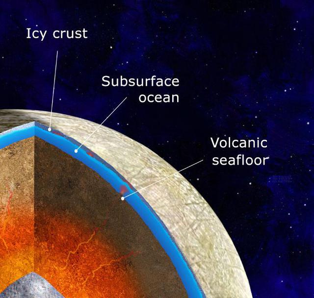
This illustration depicts scientists' findings about what the interior of Jupiter's moon Europa may look like: an iron core, surrounded by a rocky mantle believed to be in direct contact with a vast, internal ocean. New research and computer modeling show that volcanic activity may have occurred on the seafloor of Jupiter's moon Europa in the recent past – and may still be happening. The new work shows how internal heat produced by tides—warping of Europa's shape as it changes distance from Jupiter during its orbit—could partially melt its rocky layer, a process that could feed volcanoes on the ocean floor. The recent modeling of how this internal heat is produced and transferred is the most detailed and thorough examination of the effect this heating has on the moon. NASA scientists will have the opportunity to put the new predictions to the test when the agency's Europa Clipper spacecraft (aiming for a 2024 launch) reaches its target. Europa Clipper will orbit Jupiter and perform dozens of close flybys of Europa to map the moon and investigate its composition. The mission's goal is to explore whether the moon's global ocean has conditions suitable for life. https://photojournal.jpl.nasa.gov/catalog/PIA24477
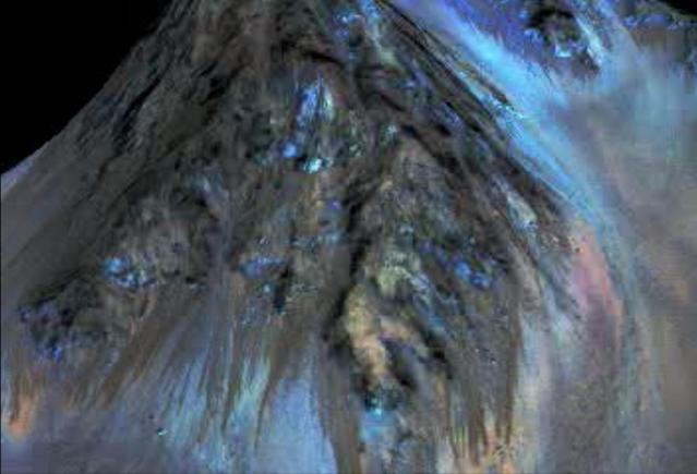
This frame from an animation simulates a fly-around look at one of the places on Mars where dark streaks advance down slopes during warm seasons, possibly involving liquid water. The streaks are roughly the length of a football field. The imaging and topographical information used in this false-color animation come from the High Resolution Imaging Science Experiment (HiRISE) camera on NASA's Mars Reconnaissance Orbiter. These dark features on the slopes are called "recurring slope lineae" or RSL. Planetary scientists using observations with the Compact Reconnaissance Imaging Spectrometer on the same orbiter detected hydrated salts on these slopes at Hale Crater, corroborating the hypothesis that the streaks are formed by briny liquid water. The image was produced by first creating a 3-D computer model (a digital terrain map) of the area based on stereo information from two HiRISE observations, and then draping a false-color image over the land-shape model. The vertical dimension is exaggerated by a factor of 1.5 compared to horizontal dimensions. http://photojournal.jpl.nasa.gov/catalog/PIA19919
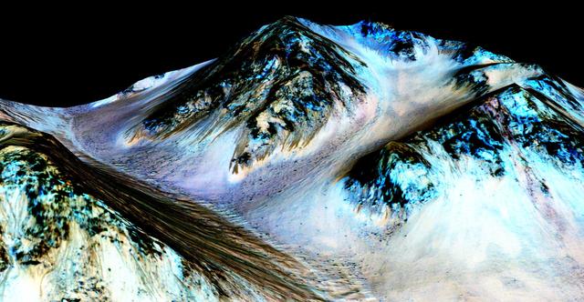
Dark, narrow streaks on Martian slopes such as these at Hale Crater are inferred to be formed by seasonal flow of water on contemporary Mars. The streaks are roughly the length of a football field. The imaging and topographical information in this processed, false-color view come from the High Resolution Imaging Science Experiment (HiRISE) camera on NASA's Mars Reconnaissance Orbiter. These dark features on the slopes are called "recurring slope lineae" or RSL. Planetary scientists using observations with the Compact Reconnaissance Imaging Spectrometer on the same orbiter detected hydrated salts on these slopes at Hale Crater, corroborating the hypothesis that the streaks are formed by briny liquid water. The image was produced by first creating a 3-D computer model (a digital terrain map) of the area based on stereo information from two HiRISE observations, and then draping a false-color image over the land-shape model. The vertical dimension is exaggerated by a factor of 1.5 compared to horizontal dimensions. The camera records brightness in three wavelength bands: infrared, red and blue-green. The draped image is one product from HiRISE observation ESP_03070_1440. http://photojournal.jpl.nasa.gov/catalog/PIA19916

Project LOLA. Test subject sitting at the controls: Project LOLA or Lunar Orbit and Landing Approach was a simulator built at Langley to study problems related to landing on the lunar surface. It was a complex project that cost nearly 2 million dollars. James Hansen wrote: This simulator was designed to provide a pilot with a detailed visual encounter with the lunar surface the machine consisted primarily of a cockpit, a closed-circuit TV system, and four large murals or scale models representing portions of the lunar surface as seen from various altitudes. The pilot in the cockpit moved along a track past these murals which would accustom him to the visual cues for controlling a spacecraft in the vicinity of the moon. Unfortunately, such a simulation--although great fun and quite aesthetic--was not helpful because flight in lunar orbit posed no special problems other than the rendezvous with the LEM, which the device did not simulate. Not long after the end of Apollo, the expensive machine was dismantled. (p. 379) Ellis J. White wrote in his paper, Discussion of Three Typical Langley Research Center Simulation Programs : A typical mission would start with the first cart positioned on model 1 for the translunar approach and orbit establishment. After starting the descent, the second cart is readied on model 2 and, at the proper time, when superposition occurs, the pilot s scene is switched from model 1 to model 2. then cart 1 is moved to and readied on model 3. The procedure continues until an altitude of 150 feet is obtained. The cabin of the LM vehicle has four windows which represent a 45 degree field of view. The projection screens in front of each window represent 65 degrees which allows limited head motion before the edges of the display can be seen. The lunar scene is presented to the pilot by rear projection on the screens with four Schmidt television projectors. The attitude orientation of the vehicle is represented by changing the lunar scene through the portholes determined by the scan pattern of four orthicons. The stars are front projected onto the upper three screens with a four-axis starfield generation (starball) mounted over the cabin and there is a separate starball for the low window. -- Published in James R. Hansen, Spaceflight Revolution: NASA Langley Research Center From Sputnik to Apollo, (Washington: NASA, 1995), p. 379 Ellis J. White, Discussion of Three Typical Langley Research Center Simulation Programs, Paper presented at the Eastern Simulation Council (EAI s Princeton Computation Center), Princeton, NJ, October 20, 1966.
Test subject sitting at the controls: Project LOLA or Lunar Orbit and Landing Approach was a simulator built at Langley to study problems related to landing on the lunar surface. It was a complex project that cost nearly $2 million dollars. James Hansen wrote: "This simulator was designed to provide a pilot with a detailed visual encounter with the lunar surface; the machine consisted primarily of a cockpit, a closed-circuit TV system, and four large murals or scale models representing portions of the lunar surface as seen from various altitudes. The pilot in the cockpit moved along a track past these murals which would accustom him to the visual cues for controlling a spacecraft in the vicinity of the moon. Unfortunately, such a simulation--although great fun and quite aesthetic--was not helpful because flight in lunar orbit posed no special problems other than the rendezvous with the LEM, which the device did not simulate. Not long after the end of Apollo, the expensive machine was dismantled." (p. 379) Ellis J. White further described this simulator in his paper , "Discussion of Three Typical Langley Research Center Simulation Programs," (Paper presented at the Eastern Simulation Council (EAI's Princeton Computation Center), Princeton, NJ, October 20, 1966.) "A typical mission would start with the first cart positioned on model 1 for the translunar approach and orbit establishment. After starting the descent, the second cart is readied on model 2 and, at the proper time, when superposition occurs, the pilot's scene is switched from model 1 to model 2. then cart 1 is moved to and readied on model 3. The procedure continues until an altitude of 150 feet is obtained. The cabin of the LM vehicle has four windows which represent a 45 degree field of view. The projection screens in front of each window represent 65 degrees which allows limited head motion before the edges of the display can be seen. The lunar scene is presented to the pilot by rear projection on the screens with four Schmidt television projectors. The attitude orientation of the vehicle is represented by changing the lunar scene through the portholes determined by the scan pattern of four orthicons. The stars are front projected onto the upper three screens with a four-axis starfield generation (starball) mounted over the cabin and there is a separate starball for the low window." -- Published in James R. Hansen, Spaceflight Revolution: NASA Langley Research Center From Sputnik to Apollo, (Washington: NASA, 1995), p. 379.
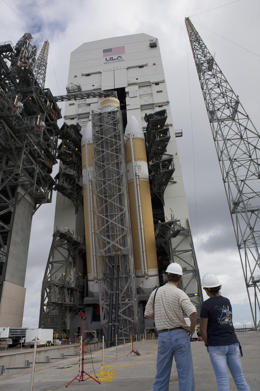
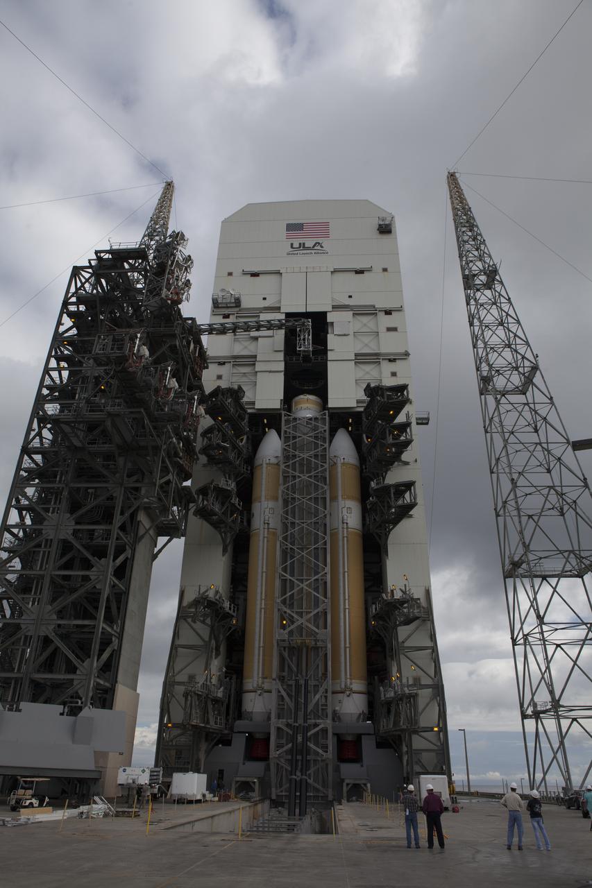
CAPE CANAVERAL, Fla. – United Launch Alliance, or ULA, workers monitor the progress as the ULA Delta IV Heavy rocket for Exploration Flight Test-1 is lifted to the vertical position in the mobile service tower on the pad at Space Launch Complex 37 at Cape Canaveral Air Force Station in Florida. The Delta IV Heavy is being readied to launch Orion on its first flight test. During its first flight test, Orion will travel farther into space than any human spacecraft has gone in more than 40 years. The data gathered during the flight will influence design decisions, validate existing computer models and innovative new approaches to space systems development, as well as reduce overall mission risks and costs for later Orion flights. Liftoff of Orion on the first flight test is planned for December 2014. Photo credit: NASA/Daniel Casper

CAPE CANAVERAL, Fla. – United Launch Alliance, or ULA, workers monitor the progress as the ULA Delta IV Heavy rocket for Exploration Flight Test-1 is lifted to the vertical position in the mobile service tower on the pad at Space Launch Complex 37 at Cape Canaveral Air Force Station in Florida. The Delta IV Heavy is being readied to launch Orion on its first flight test. During its first flight test, Orion will travel farther into space than any human spacecraft has gone in more than 40 years. The data gathered during the flight will influence design decisions, validate existing computer models and innovative new approaches to space systems development, as well as reduce overall mission risks and costs for later Orion flights. Liftoff of Orion on the first flight test is planned for December 2014. Photo credit: NASA/Daniel Casper
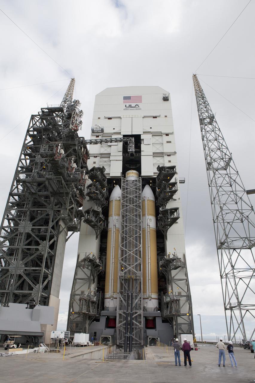
CAPE CANAVERAL, Fla. – The United Launch Alliance Delta IV Heavy rocket for Exploration Flight Test-1 is lifted to the vertical position in the mobile service tower on the pad at Space Launch Complex 37 at Cape Canaveral Air Force Station in Florida. The Delta IV Heavy is being readied to launch Orion on its first flight test. During its first flight test, Orion will travel farther into space than any human spacecraft has gone in more than 40 years. The data gathered during the flight will influence design decisions, validate existing computer models and innovative new approaches to space systems development, as well as reduce overall mission risks and costs for later Orion flights. Liftoff of Orion on the first flight test is planned for December 2014. Photo credit: NASA/Daniel Casper
The United Launch Alliance Delta IV Heavy rocket for Exploration Flight Test-1 is lifted to the vertical position in the mobile service tower on the pad at Space Launch Complex 37 at Cape Canaveral Air Force Station in Florida. The Delta IV Heavy is being readied to launch Orion on its first flight test. During its first flight test, Orion will travel farther into space than any human spacecraft has gone in more than 40 years. The data gathered during the flight will influence design decisions, validate existing computer models and innovative new approaches to space systems development, as well as reduce overall mission risks and costs for later Orion flights. Liftoff of Orion on the first flight test is planned for December 2014.
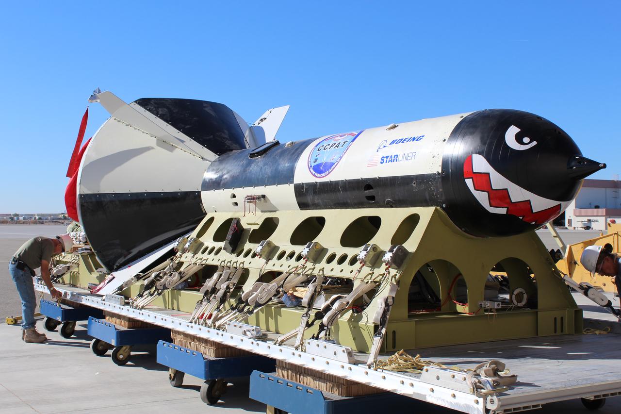
Boeing conducted the first in a series of reliability tests of its CST-100 Starliner flight drogue and main parachute system by releasing a long, dart-shaped test vehicle from a C-17 aircraft over Yuma, Arizona. Two more tests are planned using the dart module, as well as three similar reliability tests using a high fidelity capsule simulator designed to simulate the CST-100 Starliner capsule’s exact shape and mass. In both the dart and capsule simulator tests, the test spacecraft are released at various altitudes to test the parachute system at different deployment speeds, aerodynamic loads, and or weight demands. Data collected from each test is fed into computer models to more accurately predict parachute performance and to verify consistency from test to test.
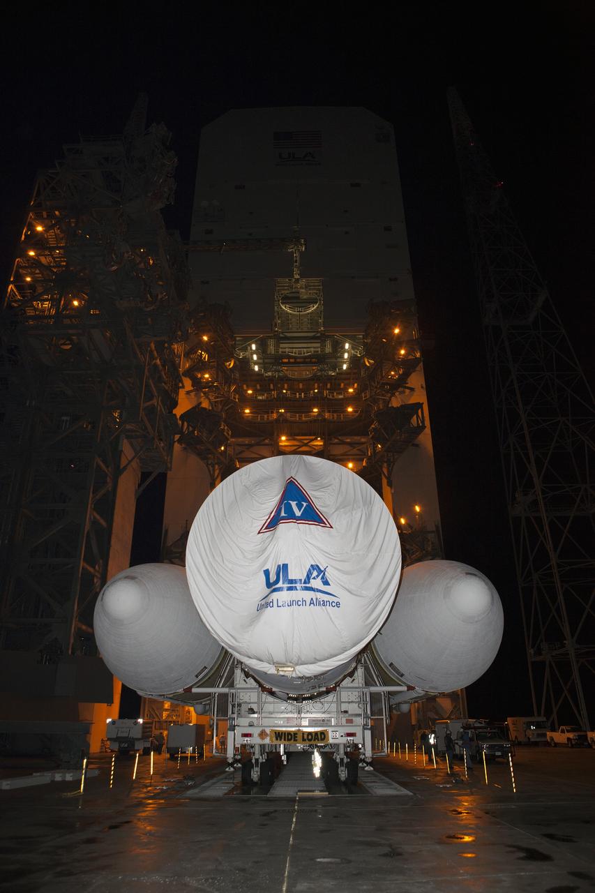
CAPE CANAVERAL, Fla. – Launch pad lights give off a golden glow at Space Launch Complex 37 at Cape Canaveral Air Force Station in Florida, as the United Launch Alliance Delta IV Heavy rocket for Exploration Flight Test-1 arrives. The rocket is secured on the Elevated Platform Transporter. The Delta IV Heavy will launch Orion on its first flight test. During its first flight test, Orion will travel farther into space than any human spacecraft has gone in more than 40 years. The data gathered during the flight will influence design decisions, validate existing computer models and innovative new approaches to space systems development, as well as reduce overall mission risks and costs for later Orion flights. Liftoff of Orion on the first flight test is planned for December 2014. Photo credit: NASA/Dimitri Gerondidakis