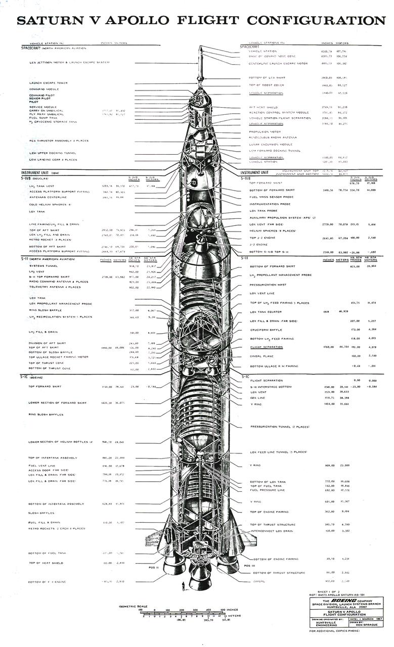
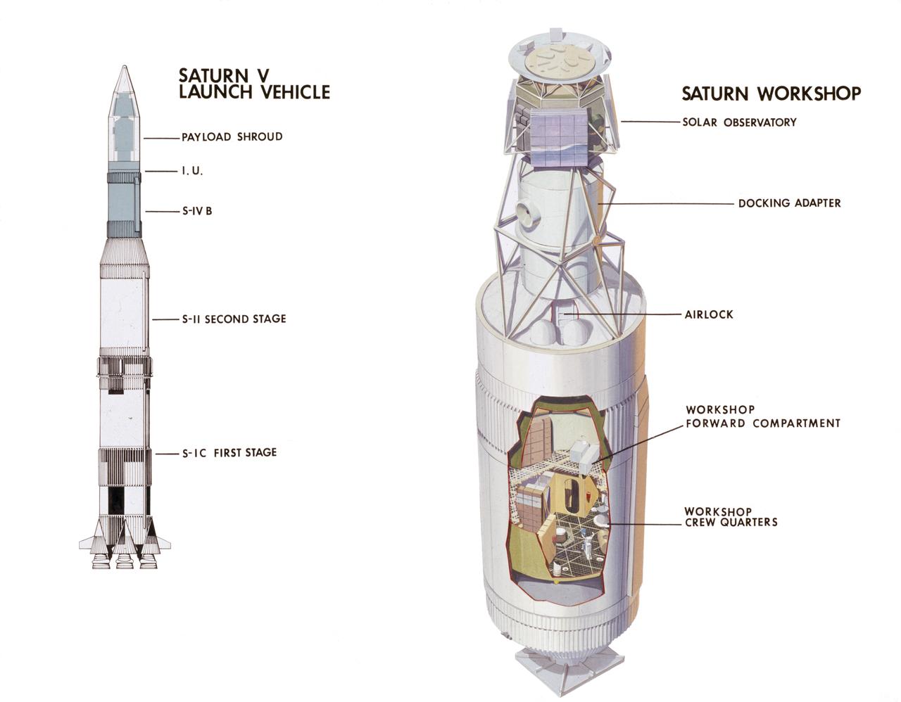
2020 International Space Station Configuration
Six iROSA solar arrays in the planned configuration will augment the power drawn from the existing arrays on the International Space Station. Power channels shown are 1A, 2B, 3A, 3B, 4A, and 4B.
ISS iROSA configuration
This illustration shows different configurations of the Saturn V test vehicles and flight vehicle.
Saturn Apollo Program
This chart illustrates the testing vehicle and flight vehicle configurations, in addition to the approximate dimensions of the stages of the Saturn V launch vehicle.
Saturn Apollo Program
NASA Pilot Nils Larson wears a U.S. Navy harness configuration to show the integrated parachute harness and the built-in survival vest. The Navy configuration is bulkier and weighs more than the U.S. Air Force harness. Both configurations are being used in the Pilot Breathing Assessment program at NASA’s Armstrong Flight Research Center in California.
U.S. Navy Harness Configuration
Photos of the eleven booster configurations
This archival photo shows the system test configuration for Voyager on October 1, 1976. The spacecraft's 10-sided bus is visible behind the catwalk railing in the foreground. The boom that holds several of the spacecraft's science instruments arches above the railing.  https://photojournal.jpl.nasa.gov/catalog/PIA21729
Voyager: System Test Configuration
AS09-21-3181 (7 March 1969) --- A View of the Apollo 9 Lunar Module (LM), "Spider," in a lunar lading configuration, as photographed from the Command and Service Modules (CSM) on the fifth day of the Apollo 9 Earth-orbital mission. The landing gear on the "Spider" has been deployed. Inside the "Spider" were astronauts James A. McDivitt, Apollo 9 commander; and Russell L. Schweickart, lunar module pilot. Astronaut David R. Scott, command module pilot, remained at the controls in the Command Module (CM), "Gumdrop," while the other two astronauts checked out the LM.
Apollo 9 Lunar Module in lunar landing configuration
AS12-51-7507 (19 Nov. 1969) --- The Apollo 12 Lunar Module (LM), in a lunar landing configuration, is photographed in lunar orbit from the Command and Service Modules (CSM). The coordinates of the center of the lunar surface shown in picture are 4.5 degrees west longitude and 7 degrees south latitude. The largest crater in the foreground is Ptolemaeus; and the second largest is Herschel. Aboard the LM were astronauts Charles Conrad Jr., commander; and Alan L. Bean, lunar module pilot. Astronaut Richard R. Gordon Jr., command module pilot, remained with the CSM in lunar orbit while Conrad and Bean descended in the LM to explore the surface of the moon. Photo credit: NASA
Apollo 12 Lunar Module, in landing configuration, photographed in lunar orbit
Spacecraft in Gravity Off-load Fixture (GOLF), System Test configuration - Arisa Waddle – Test Engineer,  Rick Wilson – Lead Test Engineer
Spacecraft in Gravity Off-load Fixture (GOLF), System Test configuration - Arisa Waddle – Test Engineer, Rick Wilson – Lead Test Engineer
Spacecraft in Gravity Off-load Fixture (GOLF), System Test configuration - Arisa Waddle – Test Engineer,  Rick Wilson – Lead Test Engineer
Spacecraft in Gravity Off-load Fixture (GOLF), System Test configuration - Arisa Waddle – Test Engineer, Rick Wilson – Lead Test Engineer
Spacecraft in Gravity Off-load Fixture (GOLF), System Test configuration - Arisa Waddle – Test Engineer,  Rick Wilson – Lead Test Engineer
Spacecraft in Gravity Off-load Fixture (GOLF), System Test configuration - Arisa Waddle – Test Engineer, Rick Wilson – Lead Test Engineer
Spacecraft in Gravity Off-load Fixture (GOLF), System Test configuration - Arisa Waddle – Test Engineer,  Rick Wilson – Lead Test Engineer
Spacecraft in Gravity Off-load Fixture (GOLF), System Test configuration - Arisa Waddle – Test Engineer, Rick Wilson – Lead Test Engineer
Spacecraft in Gravity Off-load Fixture (GOLF), System Test configuration - Arisa Waddle – Test Engineer,  Rick Wilson – Lead Test Engineer
Spacecraft in Gravity Off-load Fixture (GOLF), System Test configuration - Arisa Waddle – Test Engineer, Rick Wilson – Lead Test Engineer
Spacecraft in Gravity Off-load Fixture (GOLF), System Test configuration - Arisa Waddle – Test Engineer,  Rick Wilson – Lead Test Engineer
Spacecraft in Gravity Off-load Fixture (GOLF), System Test configuration - Arisa Waddle – Test Engineer, Rick Wilson – Lead Test Engineer
Spacecraft in Gravity Off-load Fixture (GOLF), System Test configuration - Arisa Waddle – Test Engineer,  Rick Wilson – Lead Test Engineer
Spacecraft in Gravity Off-load Fixture (GOLF), System Test configuration - Arisa Waddle – Test Engineer, Rick Wilson – Lead Test Engineer
Spacecraft in Gravity Off-load Fixture (GOLF), System Test configuration - Arisa Waddle – Test Engineer,  Rick Wilson – Lead Test Engineer
Spacecraft in Gravity Off-load Fixture (GOLF), System Test configuration - Arisa Waddle – Test Engineer, Rick Wilson – Lead Test Engineer
Spacecraft in Gravity Off-load Fixture (GOLF), System Test configuration - Arisa Waddle – Test Engineer,  Rick Wilson – Lead Test Engineer
Spacecraft in Gravity Off-load Fixture (GOLF), System Test configuration - Arisa Waddle – Test Engineer, Rick Wilson – Lead Test Engineer
Spacecraft in Gravity Off-load Fixture (GOLF), System Test configuration - Arisa Waddle – Test Engineer,  Rick Wilson – Lead Test Engineer
Spacecraft in Gravity Off-load Fixture (GOLF), System Test configuration - Arisa Waddle – Test Engineer, Rick Wilson – Lead Test Engineer
Spacecraft in Gravity Off-load Fixture (GOLF), System Test configuration - Arisa Waddle – Test Engineer,  Rick Wilson – Lead Test Engineer
Spacecraft in Gravity Off-load Fixture (GOLF), System Test configuration - Arisa Waddle – Test Engineer, Rick Wilson – Lead Test Engineer
Spacecraft in Gravity Off-load Fixture (GOLF), System Test configuration - Arisa Waddle – Test Engineer,  Rick Wilson – Lead Test Engineer
Spacecraft in Gravity Off-load Fixture (GOLF), System Test configuration - Arisa Waddle – Test Engineer, Rick Wilson – Lead Test Engineer
Spacecraft in Gravity Off-load Fixture (GOLF), System Test configuration - Arisa Waddle – Test Engineer,  Rick Wilson – Lead Test Engineer
Spacecraft in Gravity Off-load Fixture (GOLF), System Test configuration - Arisa Waddle – Test Engineer, Rick Wilson – Lead Test Engineer
Spacecraft in Gravity Off-load Fixture (GOLF), System Test configuration - Arisa Waddle – Test Engineer,  Rick Wilson – Lead Test Engineer
Spacecraft in Gravity Off-load Fixture (GOLF), System Test configuration - Arisa Waddle – Test Engineer, Rick Wilson – Lead Test Engineer
Spacecraft in Gravity Off-load Fixture (GOLF), System Test configuration - Arisa Waddle – Test Engineer,  Rick Wilson – Lead Test Engineer
Spacecraft in Gravity Off-load Fixture (GOLF), System Test configuration - Arisa Waddle – Test Engineer, Rick Wilson – Lead Test Engineer
Spacecraft in Gravity Off-load Fixture (GOLF), System Test configuration - Arisa Waddle – Test Engineer,  Rick Wilson – Lead Test Engineer
Spacecraft in Gravity Off-load Fixture (GOLF), System Test configuration - Arisa Waddle – Test Engineer, Rick Wilson – Lead Test Engineer
Spacecraft in Gravity Off-load Fixture (GOLF), System Test configuration - Arisa Waddle – Test Engineer,  Rick Wilson – Lead Test Engineer
Spacecraft in Gravity Off-load Fixture (GOLF), System Test configuration - Arisa Waddle – Test Engineer, Rick Wilson – Lead Test Engineer
This photograph shows a front view of a folded configuration of the Lunar Roving Vehicle (LRV) No. 2. The LRV was built to give Apollo astronauts a greater range of mobility during lunar exploration. It was an open-space and collapsible vehicle about 10 feet long with large mesh wheels, anterna, appendages, tool caddies, and camera. An LRV was used on each of the last three Apollo missions; Apollo 15, Apollo 16, and Apollo 17. It was built by the Boeing Company under the direction of the Marshall Space Flight Center.
Saturn Apollo Program
This photograph shows the internal configuration of Skylab's Multiple Docking Adapter (MDA), including callouts for its various internal experiments and facilities. Designed and manufactured by the Marshall Space Flight Center, the MDA housed a number of experiment control and stowage units and provided a docking port for the Apollo Command Module.
Skylab
The Gateway lunar space station configuration and major international and commercial partners.
Gateway Lunar Space Station Configuration
AS09-21-3199 (7 March 1969) --- Excellent view of the Apollo 9 Lunar Module, "Spider," in a lunar landing configuration, as photographed from the Command and Service Modules on the fifth day of the Apollo 9 Earth-orbital mission. The landing gear on the "Spider" has been deployed. Lunar surface probes (sensors) extend out from the landing gear foot pads. Inside the "Spider" were astronauts James A. McDivitt, Apollo 9 commander; and Russell L. Schweickart, lunar module pilot. Astronaut David R. Scott, command module pilot, remained at the controls in the Command Module, "Gumdrop," while the other two astronauts checked out the Lunar Module.
Apollo 9 Lunar Module in lunar landing configuration
AS09-21-3212 (7 March 1969) --- A view of the Apollo 9 Lunar Module (LM), "Spider", in a lunar landing configuration, as photographed from the Command and Service Modules (CSM) on the fifth day of the Apollo 9 Earth-orbital mission. The landing gear on the "Spider" has been deployed. Lunar surface probes (sensors) extend out from landing gear foot pads. Inside the "Spider" were astronauts James A. McDivitt, Apollo 9 commander, and Russell L. Schweickart, lunar module pilot. Astronaut David R. Scott, command module pilot, remained at the controls in the Command Module (CM), "Gumdrop", while the other two astronauts checked out the Lunar Module.
Apollo 9 Lunar Module in lunar landing configuration
The Saturn V configuration is shown in inches and meters as illustrated by the Boeing Company. The Saturn V vehicle consisted of three stages: the S-IC (first) stage powered by five F-1 engines, the S-II (second) stage powered by five J-2 engines, the S-IVB (third) stage powered by one J-2 engine. A top for the first three stages was designed to contain the instrument unit, the guidance system, the Apollo spacecraft, and the escape system. The Apollo spacecraft consisted of the lunar module, the service module, and the command module. The Saturn V was designed perform lunar and planetary missions and it was capable of placing 280,000 pounds into Earth orbit.
Saturn Apollo Program
jsc2021e009419 (3/2/2021) --- A preflight view of the passive  configuration of BIOKON. BIOKON is a facility that provides a dedicated environment to perform life science experiments in microgravity.  Image Courtesy of Kayser Italia
Biokon – Passive Configuration
jsc2021e009420 93/2/2021) --- A preflight view of the active configuration of BIOKON. BIOKON is a facility that provides a dedicated environment to perform life science experiments in microgravity.  Image Courtesy of Kayser Italia
Biokon – Active Configuration
Back dropped by the blueness of Earth is the International Space Station (ISS) as seen from Space Shuttle Discovery as the two spacecraft begin their relative separation. The latest configuration of the ISS includes the Italian-built U.S. Node 2, named Harmony, and the P6 truss segment installed over 11 days of cooperative work onboard the shuttle and station by the STS-120 and Expedition 16 crews. Undocking of the two spacecraft occurred at 4:32 a.m. (CST) on Nov. 5, 2007.
International Space Station (ISS)
Eight days of construction resumed on the International Space Station (ISS), as STS-117 astronauts and mission specialists and the Expedition 15 crew completed installation of the second and third starboard truss segments (S3 and S4). Back dropped by the blackness of space, its newly expanded configuration is revealed as pilot Lee Archambault conducts a fly around upon departure from the station on June 19, 2007.
International Space Station (ISS)
This December 1971 photograph shows the internal configuration of Skylab's Multiple Docking Adapter (MDA) as it appeared during the Crew Compartment and Function Review at the Martin-Marietta Corporation's Space Center facility in Denver, Colorado. At left is the control and display console for the Apollo Telescope Mount. Designed and manufactured by the Marshall Space Flight Center, the MDA housed a number of experiment control and stowage units and provided a docking port for the Apollo Command Module.
Skylab
Back dropped by the blackness of space and Earth's horizon is the International Space Station (ISS) as seen from Space Shuttle Discovery as the two spacecraft begin their relative separation. The latest configuration of the ISS includes the Italian-built U.S. Node 2, named Harmony, and the P6 truss segment installed over 11 days of cooperative work onboard the shuttle and station by the STS-120 and Expedition 16 crews. Undocking of the two spacecraft occurred at 4:32 a.m. (CST) on Nov. 5, 2007.
International Space Station (ISS)
Eight days of construction resumed on the International Space Station (ISS), as STS-117 astronauts and mission specialists and the Expedition 15 crew completed installation of the second and third starboard truss segments (S3 and S4). Back dropped by our colorful Earth, its  newly expanded configuration is revealed as pilot Lee Archambault conducts a fly around upon departure from the station on June 19, 2007.
International Space Station (ISS)
This cutaway drawing illustrates major Skylab components in launch configuration on top of the Saturn V. In an early effort to extend the use of Apollo for further applications, NASA established the Apollo Applications Program (AAP) in August of 1965. The AAP was to include long duration Earth orbital missions during which astronauts would carry out scientific, technological, and engineering experiments in space by utilizing modified Saturn launch vehicles and the Apollo spacecraft. Established in 1970, the Skylab Program was the forerurner of the AAP. The goals of the Skylab were to enrich our scientific knowledge of the Earth, the Sun, the stars, and cosmic space; to study the effects of weightlessness on living organisms, including man; to study the effects of the processing and manufacturing of materials utilizing the absence of gravity; and to conduct Earth resource observations. The Skylab also conducted 19 selected experiments submitted by high school students. Skylab's 3 different 3-man crews spent up to 84 days in Earth orbit. The Marshall Space Flight Center (MSFC) had responsibility for developing and integrating most of the major components of the Skylab: the Orbital Workshop (OWS), Airlock Module (AM), Multiple Docking Adapter (MDA), Apollo Telescope Mount (ATM), Payload Shroud (PS), and most of the experiments. MSFC was also responsible for providing the Saturn IB launch vehicles for three Apollo spacecraft and crews and a Saturn V launch vehicle for the Skylab.
Skylab
In response to President Reagan's directive to NASA to develop a permanent marned Space Station within a decade, part of the State of the Union message to Congress on January 25, 1984, NASA and the Administration adopted a phased approach to Station development. This approach provided an initial capability at reduced costs, to be followed by an enhanced Space Station capability in the future. This illustration depicts the baseline configuration, which features a 110-meter-long horizontal boom with four pressurized modules attached in the middle. Located at each end are four photovoltaic arrays generating a total of 75-kW of power. Two attachment points for external payloads are provided along this boom. The four pressurized modules include the following: A laboratory and habitation module provided by the United States; two additional laboratories, one each provided by the European Space Agency (ESA) and Japan; and an ESA-provided Man-Tended Free Flyer, a pressurized module capable of operations both attached to and separate from the Space Station core. Canada was expected to provide the first increment of a Mobile Serving System.
Space Station
APOLLO CONFIGURATION OF SATURN MODEL IN THE 8X6-FOOT SUPERSONIC WIND TUNNEL
APOLLO CONFIGURATION OF SATURN MODEL IN THE 8X6-FOOT SUPERSONIC
APOLLO CONFIGURATION OF SATURN MODEL IN THE 8X6-FOOT SUPERSONIC WIND TUNNEL
APOLLO CONFIGURATION OF SATURN MODEL IN THE 8X6-FOOT SUPERSONIC
APOLLO CONFIGURATION OF SATURN MODEL IN THE 8X6-FOOT SUPERSONIC WIND TUNNEL
APOLLO CONFIGURATION OF SATURN MODEL IN THE 8X6-FOOT SUPERSONIC
APOLLO CONFIGURATION OF SATURN MODEL IN THE 8X6-FOOT SUPERSONIC WIND TUNNEL
APOLLO CONFIGURATION OF SATURN MODEL IN THE 8X6-FOOT SUPERSONIC
NASA Pilot Nils Larson wears a U.S. Air Force harness configuration with a helmet and an oxygen mask that is being used in the Pilot Breathing Assessment program at NASA's Armstrong Flight Research Center in California.
U.S. Air Force Harness Configuration
Back dropped by the colorful Earth, the International Space Station (ISS) boasts its newest configuration upon the departure of Space Shuttle Endeavor and STS-118 mission. Days earlier, construction resumed on the ISS as STS-118 mission specialists and the Expedition 15 crew completed installation of the Starboard 5 (S-5) truss segment, removed a faulty Control Moment Gyroscope (CMG-3), installed a new CMG into the Z1 truss, relocated the S-band Antenna Sub-Assembly from the Port 6 (P6) to Port 1 (P1) truss, installed a new transponder on P1, retrieved the P6 transponder, and delivered roughly 5,000 pounds of supplies.
International Space Station (ISS)
Back dropped by the blue Earth, the International Space Station (ISS) boasts its newest configuration upon the departure of Space Shuttle Endeavor and STS-118 mission. Days earlier, construction resumed on the ISS as STS-118 mission specialists and the Expedition 15 crew completed installation of the Starboard 5 (S-5) truss segment, removed a faulty Control Moment Gyroscope (CMG-3), installed a new CMG into the Z1 truss, relocated the S-band Antenna Sub-Assembly from the Port 6 (P6) to Port 1 (P1) truss, installed a new transponder on P1, retrieved the P6 transponder, and delivered roughly 5,000 pounds of equipment and supplies.
International Space Station (ISS)
ISS030-E-210810 (6 April 2012) --- European Space Agency astronaut Andre Kuipers, Expedition 30 flight engineer, configures the Gas Control Panel (GCP) in the Automated Transfer Vehicle (ATV-3) currently docked with the International Space Station.
Kuipers configures the GCP in the ATV-3
ISS030-E-210829 (6 April 2012) --- European Space Agency astronaut Andre Kuipers, Expedition 30 flight engineer, configures the Gas Control Panel (GCP) in the Automated Transfer Vehicle (ATV-3) currently docked with the International Space Station.
Kuipers configures the GCP in the ATV-3
iss062e014339 (Feb. 16, 2020) --- NASA astronaut and Expedition 62 Flight Engineer Jessica Meir configures the Light Microscopy Module inside the Fluids Integrated Rack. The specialized microscope is being readied to examine the transition of an ordered crystal to a disordered glass to determine how increasing disorder affects structural and dynamic properties. The Advanced Colloids Experiment-Temperature-4 (ACE-T-4) investigation controls disorder by controlling temperature in a series of samples and observes the microscopic transition in three dimensions.
ACE-T4 Module Configuration
An artist’s rendering displays a configuration of the lunar-orbiting Gateway space station’s modules and visiting spacecraft. The core elements of Gateway consist of the Habitation and Logistics Outpost (HALO) element, the Power and Propulsion Element (PPE), and Lunar I-Hab. Visiting vehicles include the Orion spacecraft, the Logistics Module, and the Human Landing System. Gateway is built in collaboration with NASA’s commercial and international partners to serve as a multiuse space port for lunar science as humanity’s first place to live and work in lunar orbit.
Gateway Configuration Illustrations
iss057e057787 (10/31/2018) --- A view of the Life Sciences Glovebox (LSG) with Closeout Screen and Front Cover installed during rack configuration operations (OPS) in the Kibo Japanese Experiment Pressurized Module (JPM). The Life Sciences Glovebox (LSG) is a sealed work area that accommodates life science and technology investigations in a “workbench” type environment. Due to its larger size design, two crew members can work in the LSG simultaneously.
LSG Configuration, Part 2
iss062e014345 (2-16-2020) --- A view of NASA astronaut Jessica Meir configuring the Light Microscopy Module (LMM) for the Advanced Colloids Experiment-Temperature-4 (ACE-T-4) science run in the Destiny module aboard the International Space Station (ISS). Introducing disorder to a crystalline system in a controlled way can form glass. Advanced Colloids Experiment-Temperature-4 (ACE-T-4) examines the transition of an ordered crystal to a disordered glass to determine how increasing disorder affects structural and dynamic properties
ACE-T4 Module Configuration
iss062e014349 (Feb. 16, 2020) --- A view of NASA astronaut Jessica Meir configuring the Light Microscopy Module (LMM) for the Advanced Colloids Experiment-Temperature-4 (ACE-T-4) science in the Destiny module aboard the International Space Station (ISS). Introducing disorder to a crystalline system in a controlled way can form glass. Advanced Colloids Experiment-Temperature-4 (ACE-T-4) examines the transition of an ordered crystal to a disordered glass to determine how increasing disorder affects structural and dynamic properties.
ACE-T4 Module Configuration
iss062e014342 (2-16-2020) --- A view of NASA astronaut Jessica Meir configuring the Light Microscopy Module (LMM) for the Advanced Colloids Experiment-Temperature-4 (ACE-T-4) science run in the Destiny module aboard the International Space Station (ISS). Introducing disorder to a crystalline system in a controlled way can form glass. Advanced Colloids Experiment-Temperature-4 (ACE-T-4) examines the transition of an ordered crystal to a disordered glass to determine how increasing disorder affects structural and dynamic properties
ACE-T4 Module Configuration
An artist’s rendering displays a configuration of the lunar-orbiting Gateway space station’s modules and visiting spacecraft. The core elements of Gateway consist of the Habitation and Logistics Outpost (HALO) element, the Power and Propulsion Element (PPE), and Lunar I-Hab. Visiting vehicles include the Orion spacecraft, the Logistics Module, and the Human Landing System. Gateway is built in collaboration with NASA’s commercial and international partners to serve as a multiuse space port for lunar science as humanity’s first place to live and work in lunar orbit.
Gateway Configuration Illustrations
iss057e057774 (10/31/2018) --- A view of the Life Sciences Glovebox (LSG) during rack configuration operations (OPS) in the Kibo Japanese Experiment Pressurized Module (JPM). The Life Sciences Glovebox (LSG) is a sealed work area that accommodates life science and technology investigations in a “workbench” type environment. Due to its larger size design, two crew members can work in the LSG simultaneously.
LSG Configuration, Part 2
iss047e004376 (3/11/2016) --- A view during the installation and configuration of the Observation and Analysis of Smectic Islands in Space (OASIS) hardware into the Microgravity, in the U.S. Laboratory. OASIS studies the unique behavior of liquid crystals in microgravity, including their overall motion and the merging of crystal layers known as smectic islands. Liquid crystals are used for display screens in televisions and clocks and they also occur in soaps and in cell membranes. The experiment allows detailed studies of the behavior of these structures and how microgravity affects their unique ability to act like both a liquid and a solid crystal.
OASIS Installation and Configuration
This is an interior image of a Dragon spacecraft representative of the Crew-8 spacecraft configuration ahead of launch. It shows four standard crew seats and three cargo locations below upon which the crew has the capability to build temporary seat structures for returning additional crew from station as needed. Since docking, the Crew-8 Dragon’s interior has been reconfigured to provide an emergency return capability for Expedition 72 crewmembers Butch Wilmore and Suni Williams in locations C7 and C5 until the Crew-9 Dragon arrives.
Dragon Crew Seat Configuration
ISS047e066551 (04/18/2016) --- NASA astronaut Jeff Williams configures the station’s Light Microscopy Module (LMM), a modified commercial, highly flexible, state-of-the-art light imaging microscope facility that provides researchers with powerful diagnostic hardware and software. The LMM enables novel research of microscopic phenomena in microgravity, with the capability of remotely acquiring and downloading digital images and videos across many levels of magnification.
Williams configures the LMM
iss072e472714 (Jan. 14, 2025) --- NASA astronaut and Expedition 72 Flight Engineer Butch Wilmore configures spacewalking hardware aboard the International Space Station's Unity module.
Astronaut Butch Wilmore configures spacewalking hardware
JSC2007-E-099883 (November 2007) --- Computer-generated artist's rendering of the 10A stage configuration of the International Space Station as of Nov. 15, 2007. The port side Thermal Control System radiators are fully deployed.
Current Configuration of the ISS for use on HSF website
The solar arrays on NASA's InSight lander are deployed in this test inside a clean room at Lockheed Martin Space Systems, Denver. This configuration is how the spacecraft will look on the surface of Mars. The image was taken on April 30, 2015.  InSight, for Interior Exploration Using Seismic Investigations, Geodesy and Heat Transport, is scheduled for launch in March 2016 and landing in September 2016. It will study the deep interior of Mars to advance understanding of the early history of all rocky planets, including Earth.  Note: After thorough examination, NASA managers have decided to suspend the planned March 2016 launch of the Interior Exploration using Seismic Investigations Geodesy and Heat Transport (InSight) mission. The decision follows unsuccessful attempts to repair a leak in a section of the prime instrument in the science payload.  http://photojournal.jpl.nasa.gov/catalog/PIA19664
InSight Lander in Mars-Surface Configuration
The Gateway space station will be humanity's first space station around the Moon as a vital component of the Artemis missions to return humans to the lunar surface for scientific discovery and chart the path for the first human missions to Mars. Astronauts on Gateway will be the first humans to call deep space home during missions where they will use Gateway to conduct science and prepare for lunar surface missions.
Gateway - Full Configuration Hero Image - 121123
iss059e061932 (5/17/2019) --- Photo documentation onboard the International Space Station (ISS) of the ACE Modules taken during the ACE-T12 Module Configuration.  The Advanced Colloids Experiment-Nanoparticle Haloing (ACE-T-12) involves design and assembly of complex three-dimensional (3D) structures from colloids, or particles of different sizes suspended in a fluid. It employs a recently discovered technique, Nanoparticle Haloing (NPH), which uses highly charged nanoparticles to stabilize much larger, non-charged particles. Allowing these structures to form in microgravity provides insight into the relationship between shape, surface charge, and concentration of particles and particle interactions.
ACE-T12 Module Configuration
JSC2007-E-099882 (November 2007) --- Computer-generated artist's rendering of the 10A stage configuration of the International Space Station as of Nov. 14, 2007. The Harmony node with Pressurized Mating Adapter (PMA-2) attached is relocated to the front of the Destiny laboratory.
Current Configuration of the ISS for use on HSF website
iss067e003895 (April 6, 2022) --- NASA astronaut and Expedition 67 Commander Thomas Marshburn configures the Combustion Integrated Rack's combustion chamber for the Solid Fuel Ignition and Extinction study to investigate material flammability and ways to improve fire safety in space.
SoFIE Chamber Insert Configuration, Part 2
JSC2007-E-099881 (November 2007) --- Computer-generated artist's rendering of the 10A stage configuration of the International Space Station as of Nov. 12, 2007. Pressurized Mating Adapter (PMA-2) is relocated from the front of the Destiny laboratory to the port side of the Harmony node.
Current Configuration of the ISS for use on HSF website
NASA research pilot Jim Less wears a U.S. Navy harness configuration with the NASA Jet Propulsion Laboratory in California prototype mask, which uses laser sensors to determine levels of carbon dioxide and water exhaled inside the mask. This prototype was tested in conjunction with the current VigilOX system, which measures the pilot’s oxygen concentration, breathing pressures and flow rates. This and the U.S. Air Force configuration was used in the Pilot Breathing Assessment program at NASA’s Armstrong Flight Research Center in California.
Pilot Breathing Assessment Program Prototype JPL Mask with U.S. Navy Configuration
iss073e0252488 (June 28, 2025) --- Axiom Mission 4 (Ax-4) Commander Peggy Whitson from the U.S. configures research hardware aboard the International Space Station's Destiny laboratory module.
Axiom Mission 4 Commander Peggy Whitson configures research hardware
Photographed from the Space Shuttle Discovery upon its separation from the orbital outpost, the International Space Station (ISS) is shown sporting its new additions. A fly-around gave the crew a look at their handiwork, a new P5 spacer truss segment and a fully retracted P6 solar array wing. Earlier, the STS-116 and Expedition 14 crews concluded eight days of cooperative work onboard the shuttle and station where they accomplished the installation of the newest piece of the station and completely rewired the power grid over the course of four space walks. The station is currently the size of a typical three-bedroom house, with a surface area large enough to cover four basketball courts. The image reflects the latest configuration of the ISS as of December 19, 2006.
n/a
S66-31019 (May 1966) --- Test subject Fred Spross, Crew Systems Division, wears the Gemini-9 configured extravehicular spacesuit assembly. The legs are covered with Chromel R, which is a cloth woven from stainless steel fibers, used to protect the astronaut and suit from the hot exhaust thrust of the Astronaut Maneuvering Unit (AMU). Astronaut Eugene A. Cernan will wear this spacesuit during his Gemini-9A extravehicular activity (EVA). Photo credit: NASA
Gemini 9 configured extravehicular spacesuit assembly
JSC2011-E-072138 (July 2011) --- Computer-generated artist?s rendering of the port view of the complete configuration of the International Space Station as of July 18, 2011, following the STS-135 mission. Progress 43 is linked to the aft port of the Zvezda Service Module. Soyuz 27 (TMA-02M) is docked to the Rassvet Mini-Research Module 1 (MRM1). Progress 42 is attached to the Pirs Docking Compartment and Soyuz 26 (TMA-21) is docked to the Poisk Mini-Research Module 2 (MRM2). Photo credit: NASA
Current Configurations of ISS for use on HSF web
ISS046e005678 (01/04/2016) ---- ESA (European Space Agency) astronaut Tim Peake works on the Advanced Colloids Experiment 2 (ACE H2) Hardware Configuration and Mix Part 1. Peake sent out a Twitter message with this image: Stirring samples using a bar magnet to turn a tiny metal rod - preparing for today's @ISS_Research. #Principia".
ACE H2 Hardware Configuration and Mix Part 1
JSC2011-E-072139 (July 2011) --- Computer-generated artist?s rendering of the starboard view of the complete configuration of the International Space Station as of July 18, 2011, following the STS-135 mission. Progress 43 is linked to the aft port of the Zvezda Service Module. Soyuz 27 (TMA-02M) is docked to the Rassvet Mini-Research Module 1 (MRM1). Progress 42 is attached to the Pirs Docking Compartment and Soyuz 26 (TMA-21) is docked to the Poisk Mini-Research Module 2 (MRM2). Photo credit: NASA
Current Configurations of ISS for use on HSF web
Scale-model of final X-15 configuration, mounted for testing in the Langley 11-Inch Hypersonic Tunnel.
S66-21296 (1967) --- This is a medium exterior view of the Dynamic Crew Procedures Trainer, Command Module configuration, one of the Apollo astronaut training components located in the Mission Simulation and Training Facility, Building 5, Manned Spacecraft Center, Houston, Texas. Photo credit: NASA
Closeup exterior view of Dynamic Crew Procedures Trainer
PHOTO DATE: 06-23-11 LOCATION:  Bldg 9nw, ISS Mockups SUBJECT: Expedition 29 crew members, Dan Burbank, Don Pettit and Andre Kuiper during ISS EVA Tool Configuration with instructor Sandra Moore WORK ORDER:  2011-1764 PHOTOGRAPHER:  James Blair
Expedition 29 crew members during ISS EVA Tool Configuration
Alejandro Rodriguez Perez and Joe Thomes, members of the fiber optic & photonic team, configure the Ocean Color Instrument (OCI) Engineering Test Unit (ETU) Shortwave Infrared (SWIR) Detector Asembly and  Multi-lens Array (MLA) fibers for thermal testing.  OCI is a highly advanced optical spectrometer that will be used to measure properties of light over portions of the electromagnetic spectrum. It will enable continuous measurement of light at finer wavelength resolution than previous NASA satellite sensors, extending key system ocean color data records for climate studies. OCI is PACE's (Plankton, Aerosol, Cloud, ocean Ecosystem) primary sensor built at Goddard Space Flight Center in Greenbelt, MD.
OCI Fiber Optic and Photonic Team Configure Fibers
JSC2006-E-38949 (August 2006) --- Computer generated graphic of the International Space Station configuration after STS-115/12A with the addition of the P3/P4 integrated truss segments.
ISS Configurations during STS-115, STS-116, and STS-117 from Expedition 14 Press Kit
JSC2006-E-38950 (August 2006) --- Computer generated graphic of the International Space Station configuration after STS-116/12A.1 with the addition of the P5 integrated truss segment.
ISS Configurations during STS-115, STS-116, and STS-117 from Expedition 14 Press Kit
JSC2006-E-38951 (August 2006) --- Computer generated graphic of the International Space Station configuration after STS-117/13A with the addition of S3/S4 integrated truss segments.
ISS Configurations during STS-115, STS-116, and STS-117 from Expedition 14 Press Kit
iss057e059103 (11/7/2018) --- Photo documentation of the area behind the Common Berthing Mechanism (CBM) Center Disk Cover in the Harmony Node 2 nadir hatch during part 2 of Kounotori H-II Transfer Vehicle 7 (HTV-7) Vestibule configuration for demating. The HTV Small Re-entry Capsule (HSRC) Protective Cover has been removed.
HTV Vestibule Configure for Demate from Node 2 Nadir, Part 2
ISS034-E-051798 (21 Feb. 2013) --- NASA astronaut Tom Marshburn, Expedition 34 flight engineer, configures one of the experiment racks in the U.S. lab called Destiny aboard the International Space Station in Earth orbit.  ACE produces microscopic images of materials which contain small colloidal particles, and it examines flow characteristics and the evolution and ordering effects within these colloidal materials in 1-G and micro-G environments.
Marshburn configures FIR/LMM ACE hardware, in the U.S. Laboratory
iss071e522127 (Aug. 21, 2024) --- NASA astronaut and Expedition 71 Flight Engineer Jeanette Epps configures the Metal 3D printer that manufactures experimental samples printed with stainless steel aboard the International Space Station's Columbus laboratory module. Researchers are exploring how the Metal 3D printer operates in the microgravity conditions of weightlessness and radiation as well as its ability to manufacture tools and parts on demand during space missions.
NASA astronaut Jeanette Epps configures the Metal 3D printer
iss057e059085 (11/7/2018) --- Photo documentation of the Common Berthing Mechanism (CBM) Center Disk Cover in the Harmony Node 2 nadir hatch during part 2 of Kounotori H-II Transfer Vehicle 7 (HTV-7) Vestibule configuration for demating. The HTV Small Re-entry Capsule (HSRC) Protective Cover has been removed.
HTV Vestibule Configure for Demate from Node 2 Nadir, Part 2
iss073e0982900 (Oct. 28, 2025) --- Expedition 73 Flight Engineers Mike Fincke of NASA and Kimiya Yui of JAXA (Japan Aerospace Exploration Agency) work together to configure research hardware for the Zero Boil-Off Tank physics investigation inside the Microgravity Science Glovebox aboard the International Space Station. The experiment explores methods for storing cryogenic fluids and supports advancements in spacecraft propulsion and life support systems, as well as biotechnological, medical, and industrial applications on Earth.
Astronauts Mike Fincke and Kimiya Yui work together to configure research hardware
An artist’s concept of the transonic truss-braced wing aircraft configuration in flight over a forest of trees.
NASA Rover 1 in the cruise configuration in Jet Propulsion Laboratory 25-ft Solar Thermal Vacuum Chamber where it underwent environmental testing.
Environmental Testing