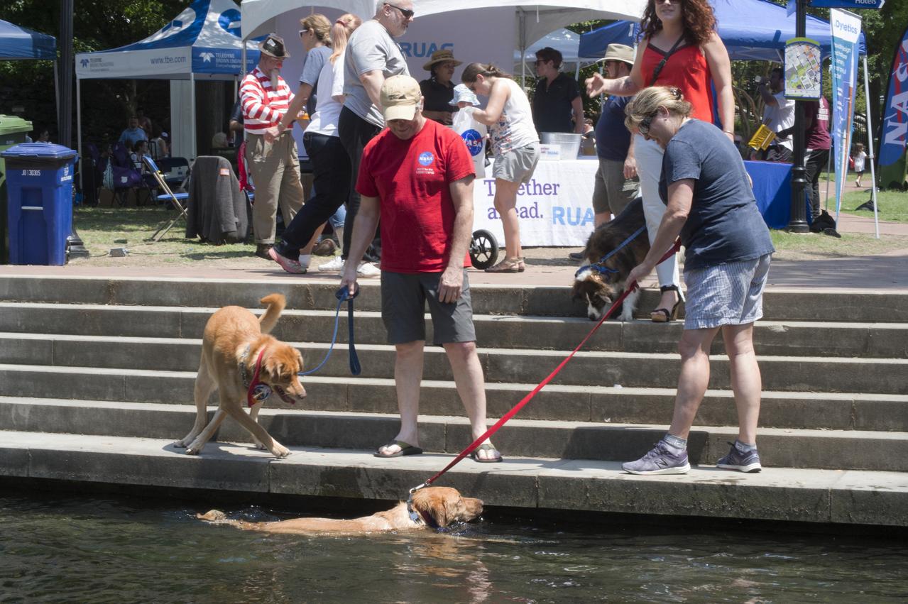
NASA in the Park on June 16 in Huntsville featured more than 60 exhibits and demonstrations by NASA experts, as well as performances by Marshall musicians, educational opportunities, games and hands-on activities for all ages. Big Spring canal is a good place to cool off in the 90 degree heat
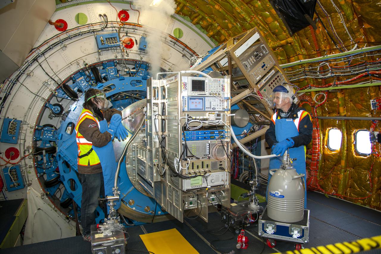
Technicians introduce liquid nitrogen to an instrument linked to SOFIA’s telescope. Detection of infrared wavelengths is greatly enhanced by removing as much heat from the telescope as possible.
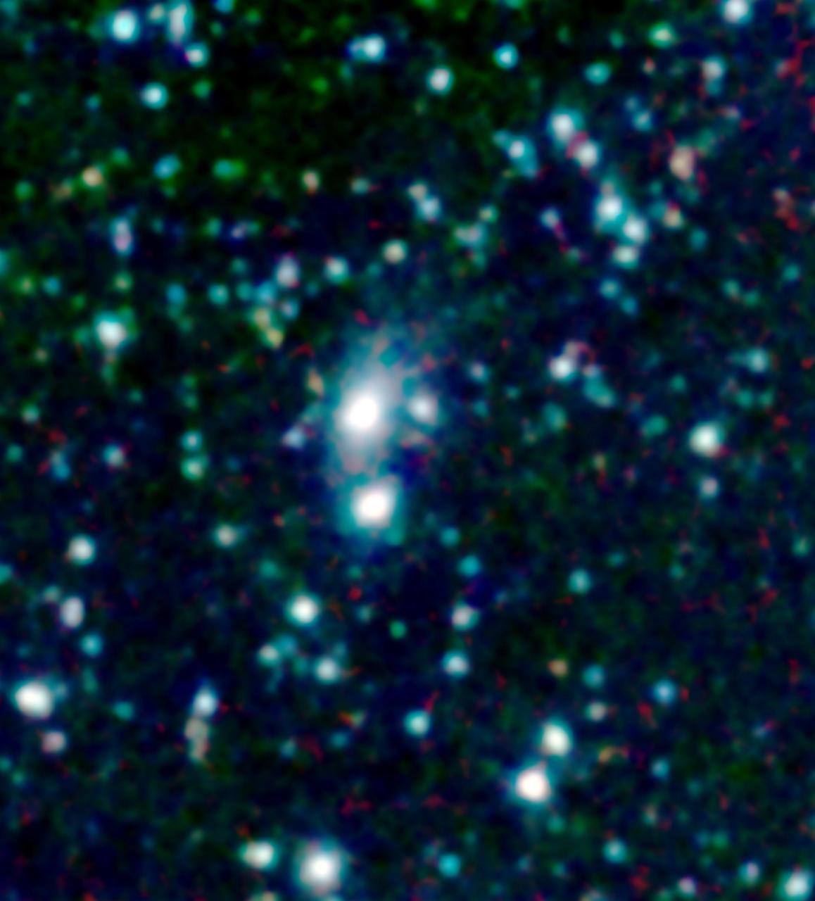
A big galaxy is stealing gas right off the back of its smaller companion in this new image from NASA Spitzer Space Telescope. The stolen gas is hot, but it might eventually cool down to make new stars and planets.
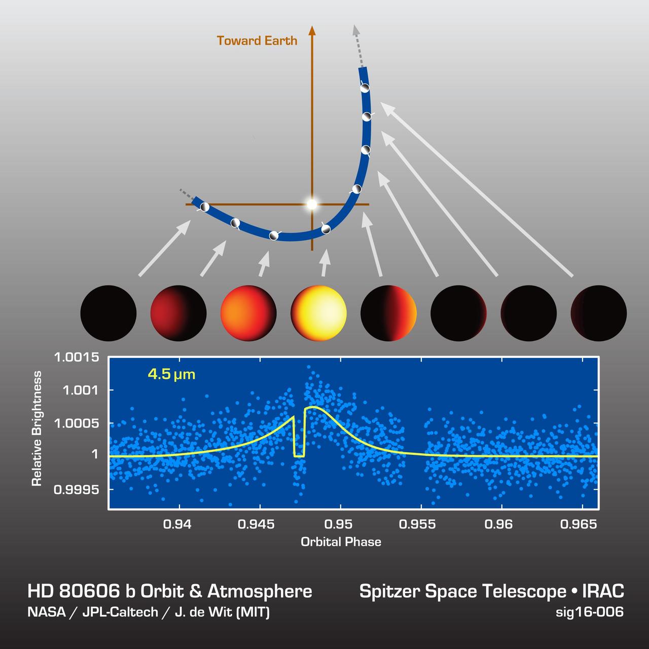
Astronomers watched an exoplanet called HD 80606b heat up and cool off during its sizzling-hot orbit around its star. The results are shown in this data plot from NASA Spitzer Space Telescope.
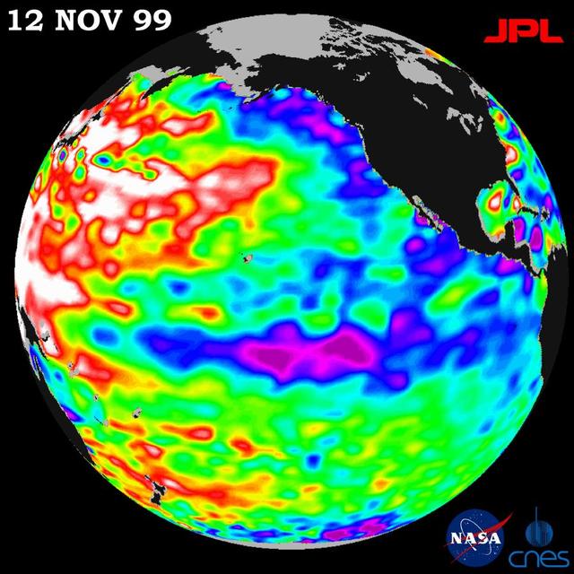
Unusually warm ocean temperatures off Asia and cool waters in the eastern and equatorial Pacific are signaling La Niña mild return, according to the latest sea-surface heights observed by the joint NASA-French space agency TOPEX/Poseidon satellite.
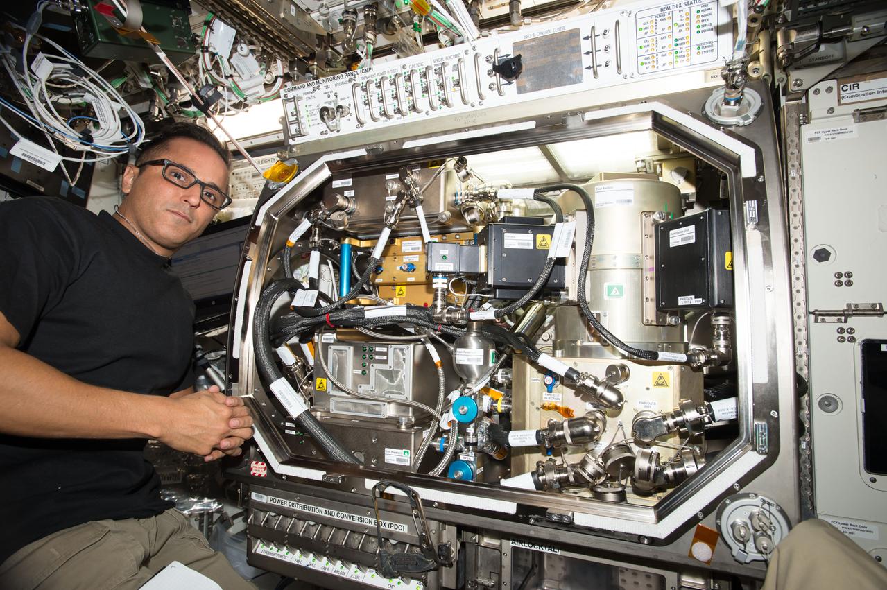
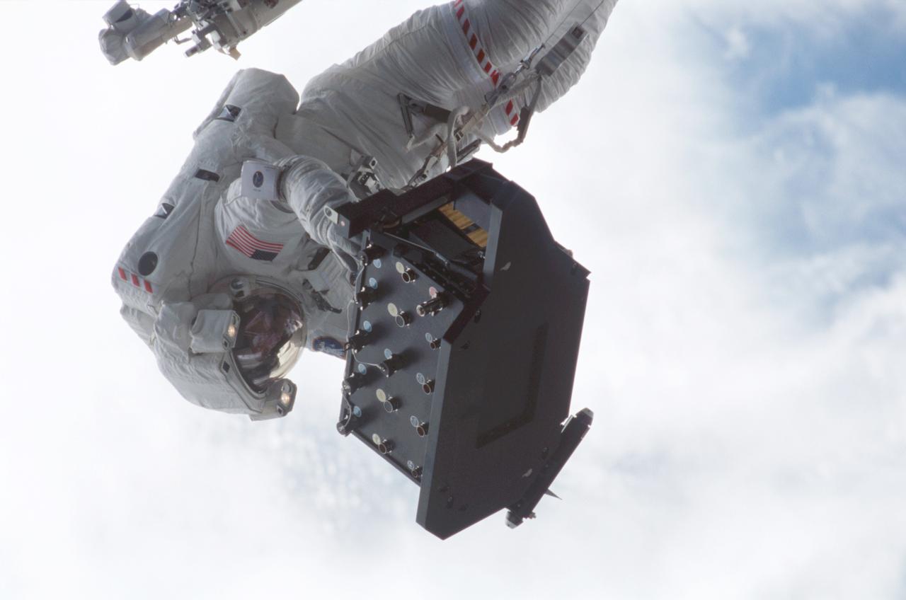
iss053e027051 (Sept. 19, 2017) --- Flight Engineer Joe Acaba works in the U.S. Destiny laboratory module setting up hardware for the Zero Boil-Off Tank (ZBOT) experiment. ZBOT uses an experimental fluid to test active heat removal and forced jet mixing as alternative means for controlling tank pressure for volatile fluids. Rocket fuel, spacecraft heating and cooling systems, and sensitive scientific instruments rely on very cold cryogenic fluids. Heat from the environment around cryogenic tanks can cause their pressures to rise, which requires dumping or "boiling off" fluid to release the excess pressure, or actively cooling the tanks in some way.
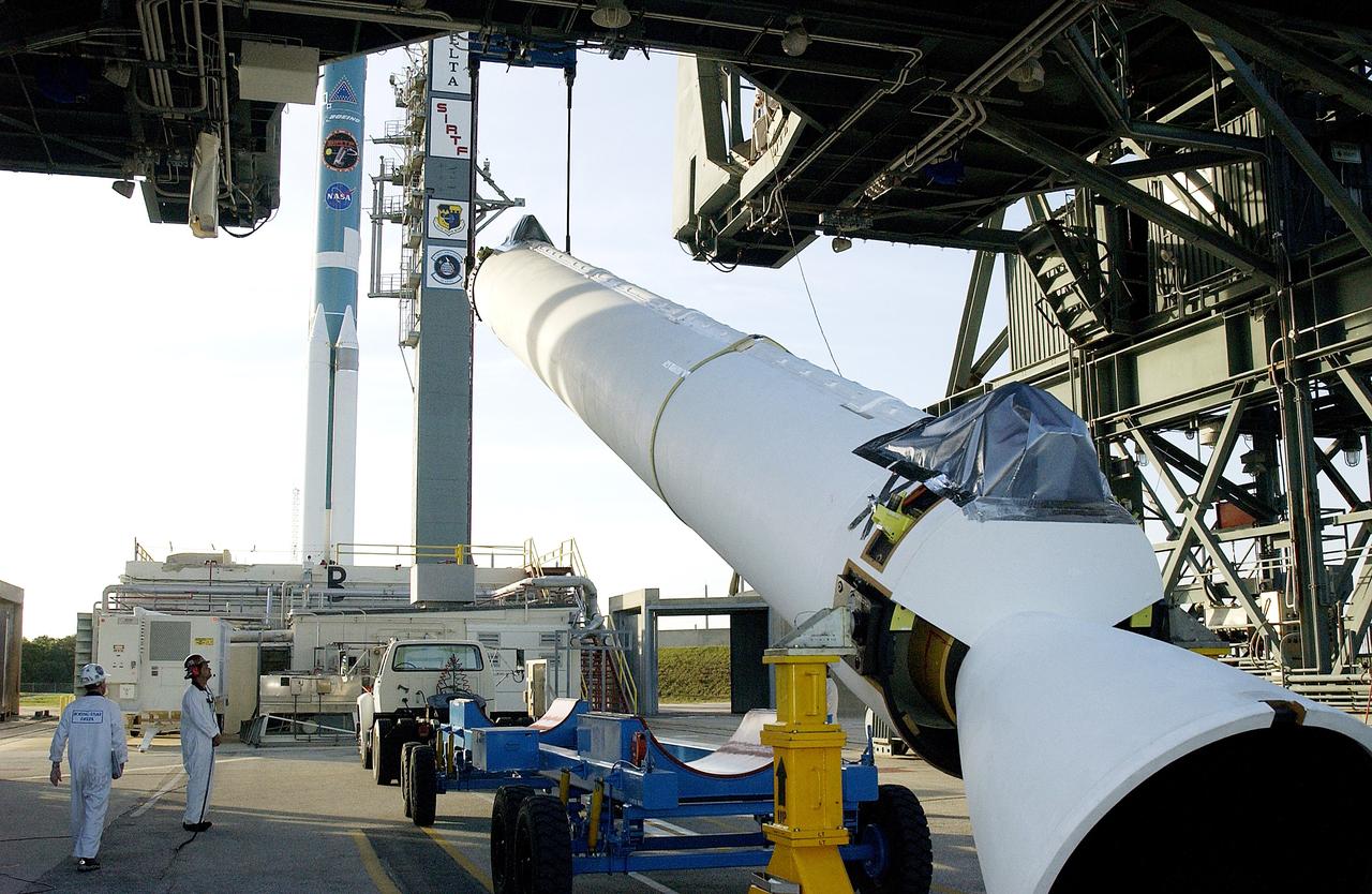
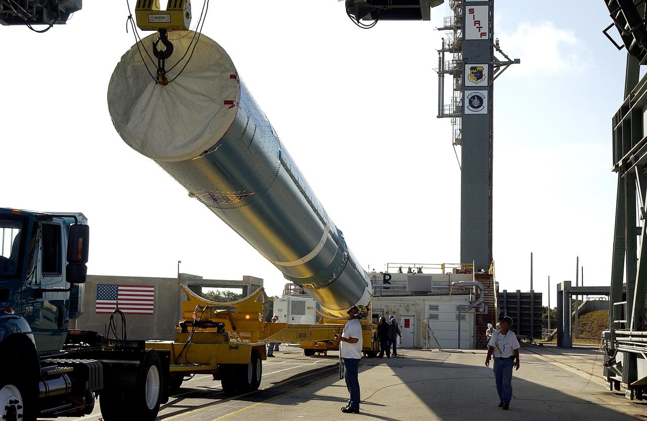
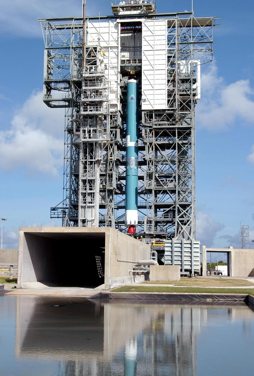
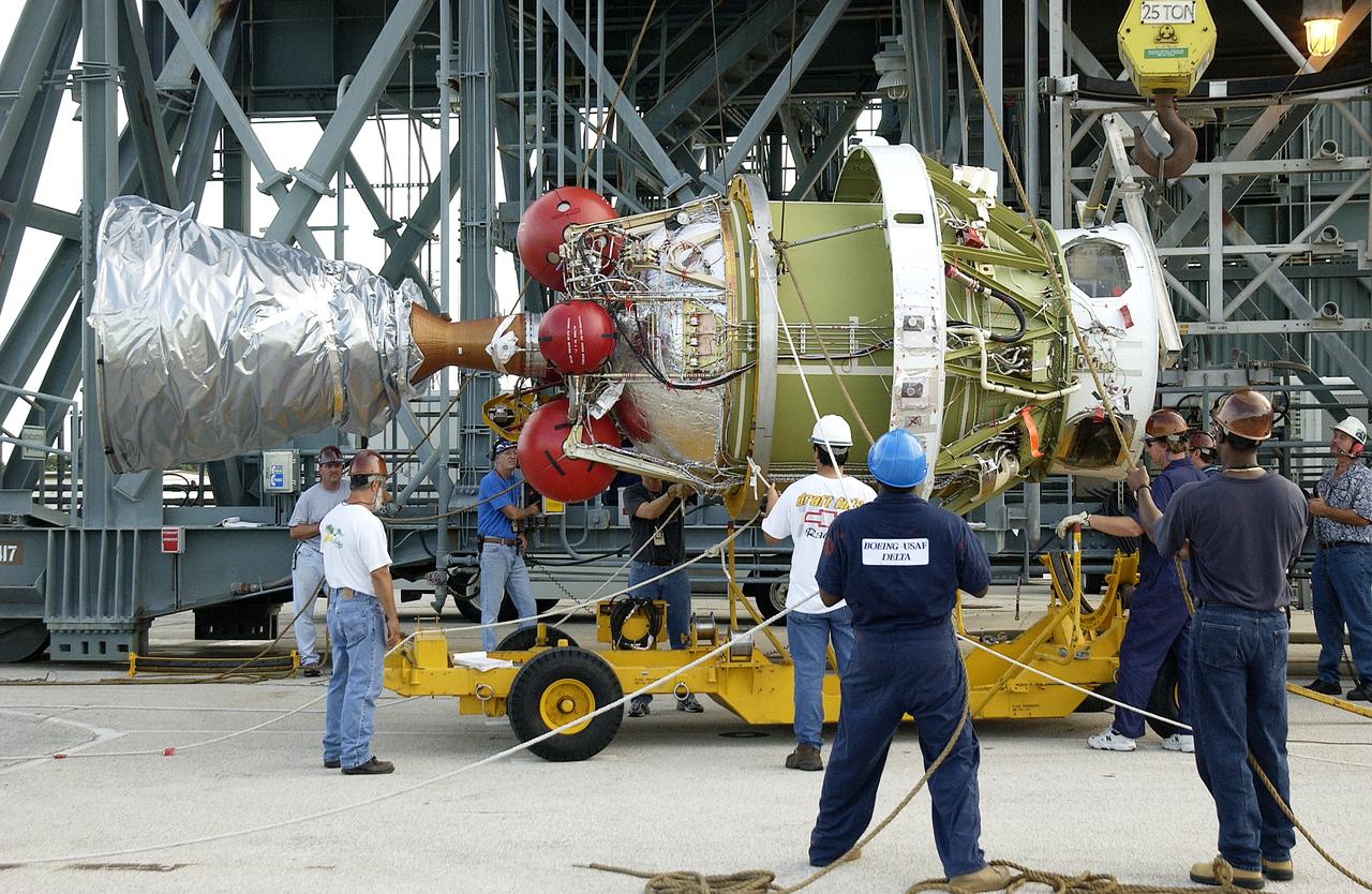
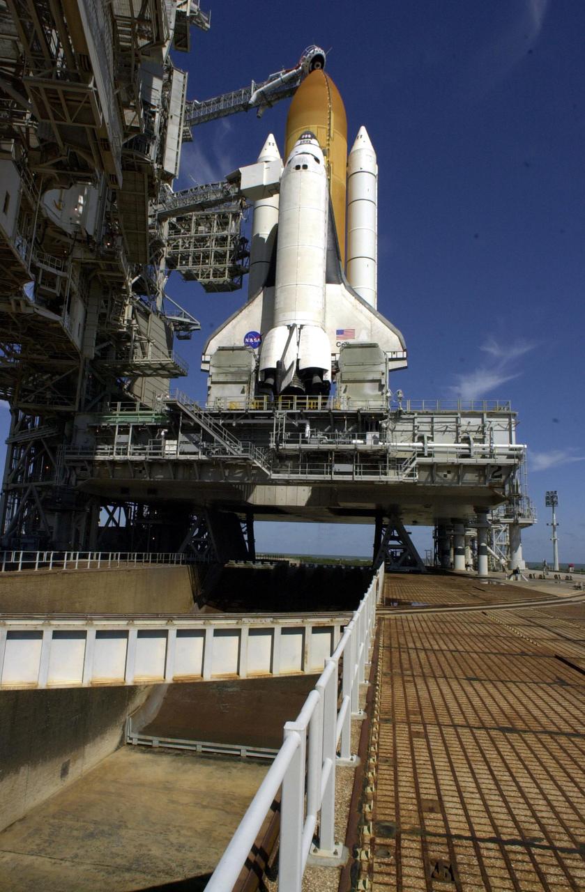
KENNEDY SPACE CENTER, FLA. - A solid rocket booster (SRB) for the Delta II Heavy rocket that will launch the Space Infrared Telescope Facility (SIRTF) is lifted off its transporter on Launch Complex 17-B, Cape Canaveral Air Force Station. The SRB will be added to the launch vehicle in the background. The Delta II Heavy features nine 46-inch-diameter, stretched SRBs. SIRTF, consisting of three cryogenically cooled science instruments and an 0.85-meter telescope, is one of NASA's largest infrared telescopes to be launched. SIRTF will obtain images and spectra by detecting the infrared energy, or heat, radiated by objects in space. Most of this infrared radiation is blocked by the Earth's atmosphere and cannot be observed from the ground.
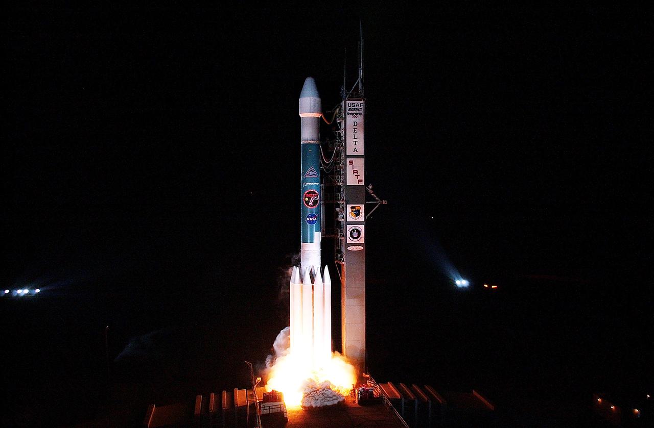
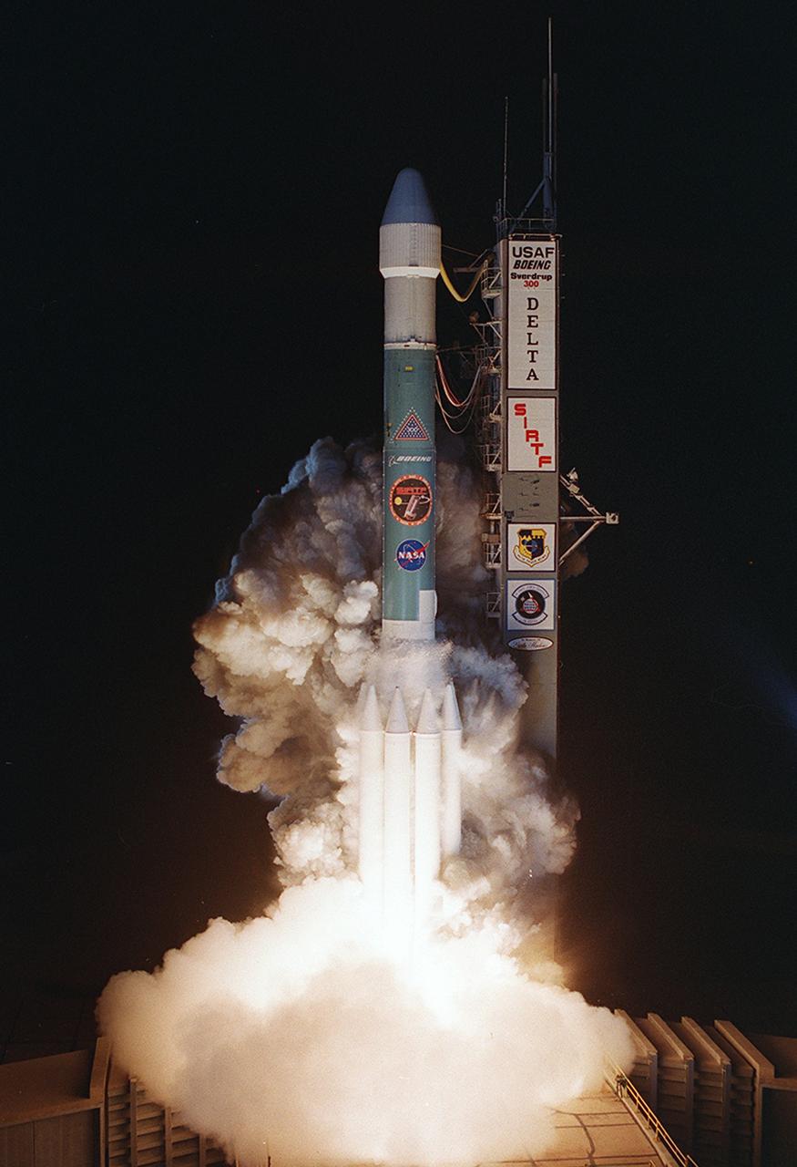
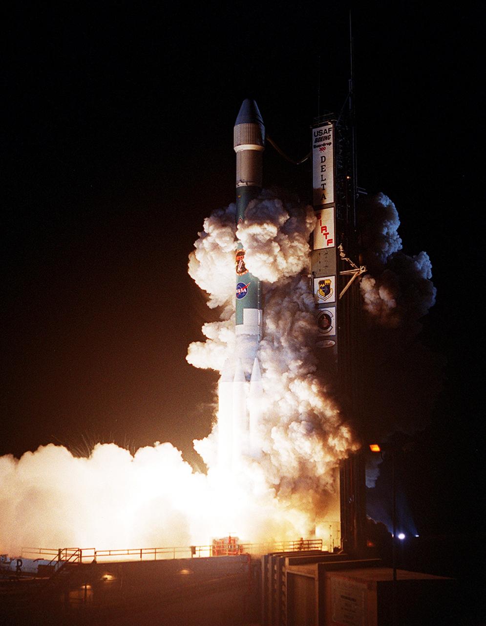
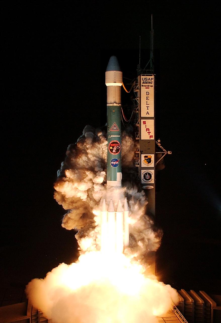
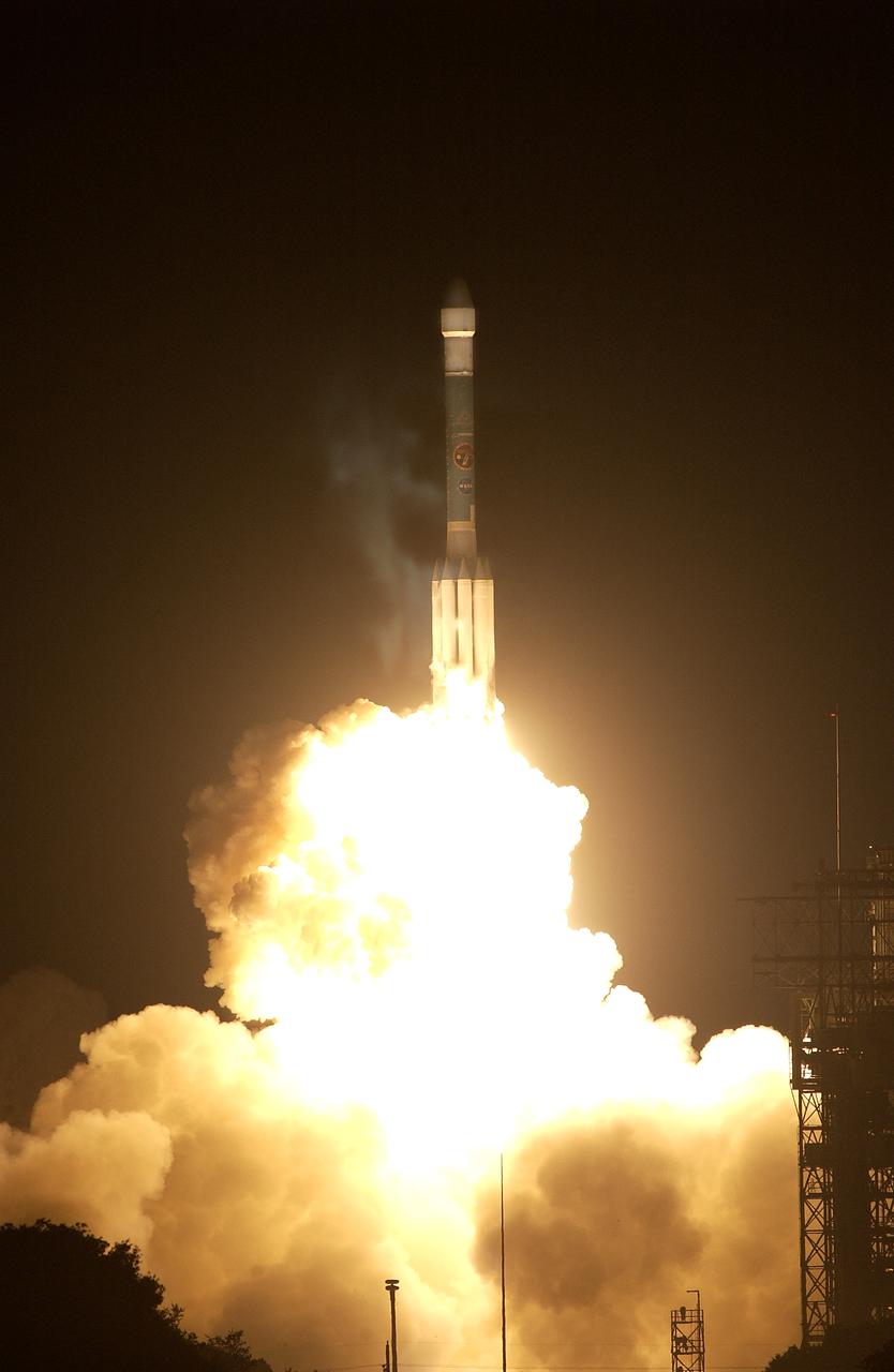
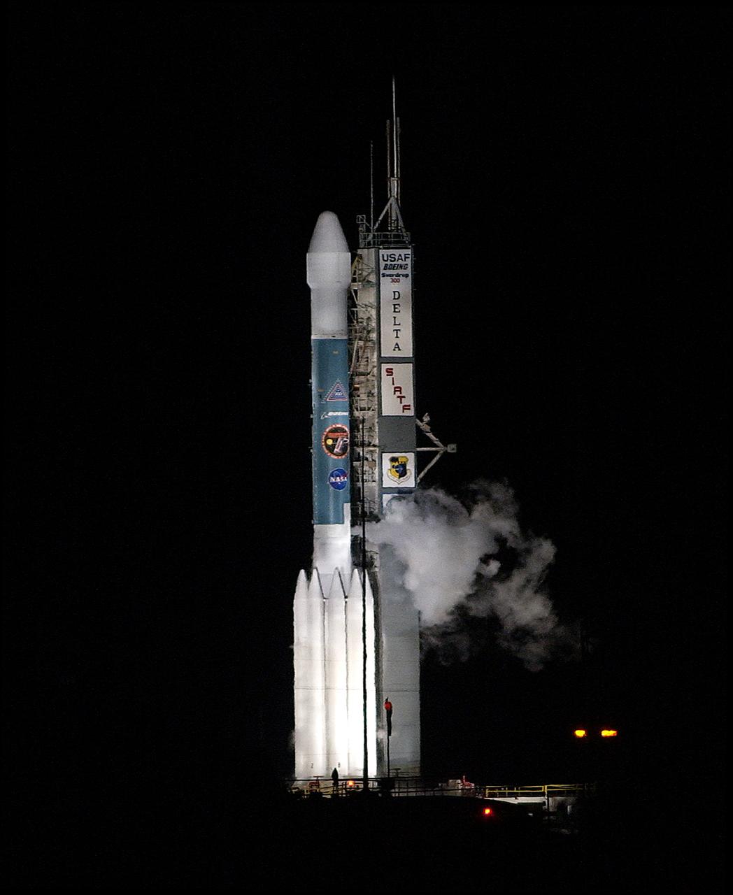
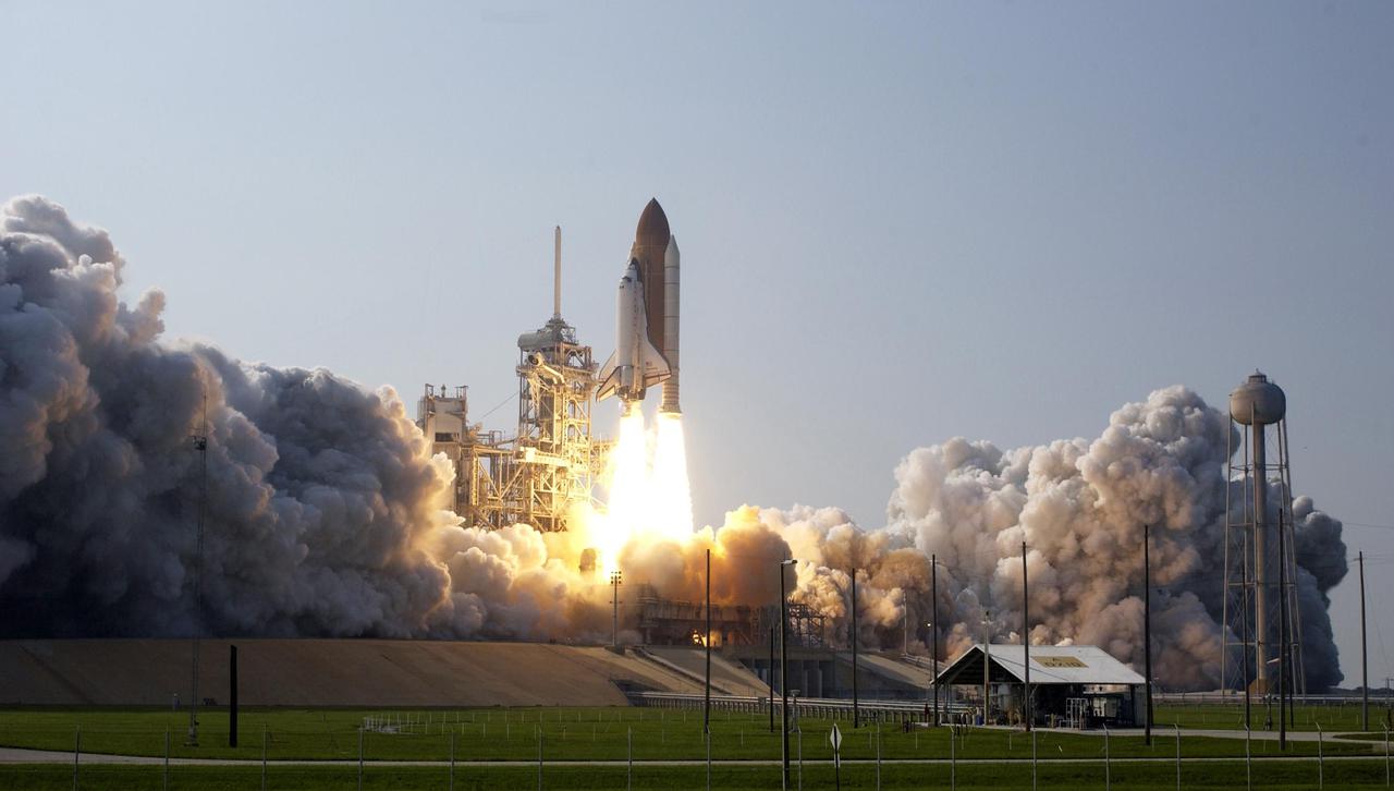
KENNEDY SPACE CENTER, FLA. - NASA's Space Infrared Telescope Facility (SIRTF) lifts off from Launch Pad 17-B, Cape Canaveral Air Force Station, on Aug. 25 at 1:35:39 a.m. EDT. SIRTF will obtain images and spectra by detecting the infrared energy, or heat, radiated by objects in space. Consisting of a 0.85-meter telescope and three cryogenically cooled science instruments, SIRTF will be the largest infrared telescope ever launched into space. It is the fourth and final element in NASA’s family of orbiting “Great Observatories.” Its highly sensitive instruments will give a unique view of the Universe and peer into regions of space that are hidden from optical telescopes.
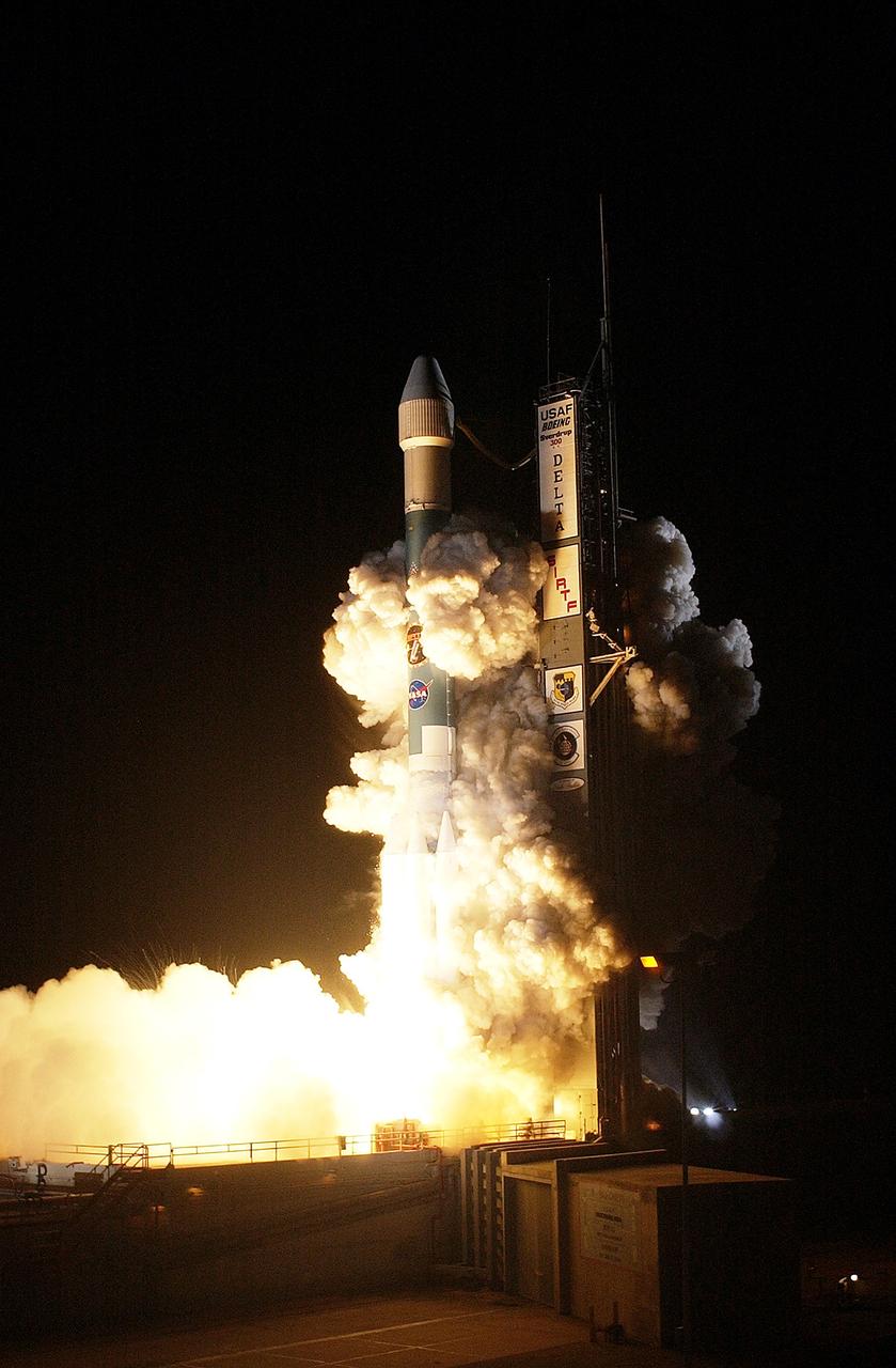
KENNEDY SPACE CENTER, FLA. - NASA's Space Infrared Telescope Facility (SIRTF) lifts off from Launch Pad 17-B, Cape Canaveral Air Force Station, on Aug. 25 at 1:35:39 a.m. EDT. SIRTF will obtain images and spectra by detecting the infrared energy, or heat, radiated by objects in space. Consisting of a 0.85-meter telescope and three cryogenically cooled science instruments, SIRTF will be the largest infrared telescope ever launched into space. It is the fourth and final element in NASA’s family of orbiting “Great Observatories.” Its highly sensitive instruments will give a unique view of the Universe and peer into regions of space that are hidden from optical telescopes.
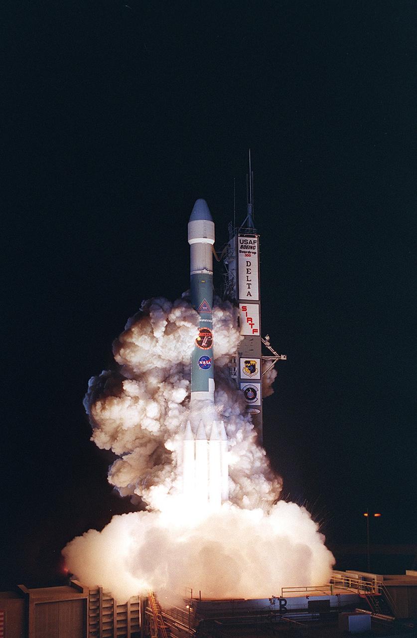
KENNEDY SPACE CENTER, FLA. - NASA's Space Infrared Telescope Facility (SIRTF) lifts off from Launch Pad 17-B, Cape Canaveral Air Force Station, on Aug. 25 at 1:35:39 a.m. EDT. SIRTF will obtain images and spectra by detecting the infrared energy, or heat, radiated by objects in space. Consisting of a 0.85-meter telescope and three cryogenically cooled science instruments, SIRTF will be the largest infrared telescope ever launched into space. It is the fourth and final element in NASA’s family of orbiting “Great Observatories.” Its highly sensitive instruments will give a unique view of the Universe and peer into regions of space that are hidden from optical telescopes.
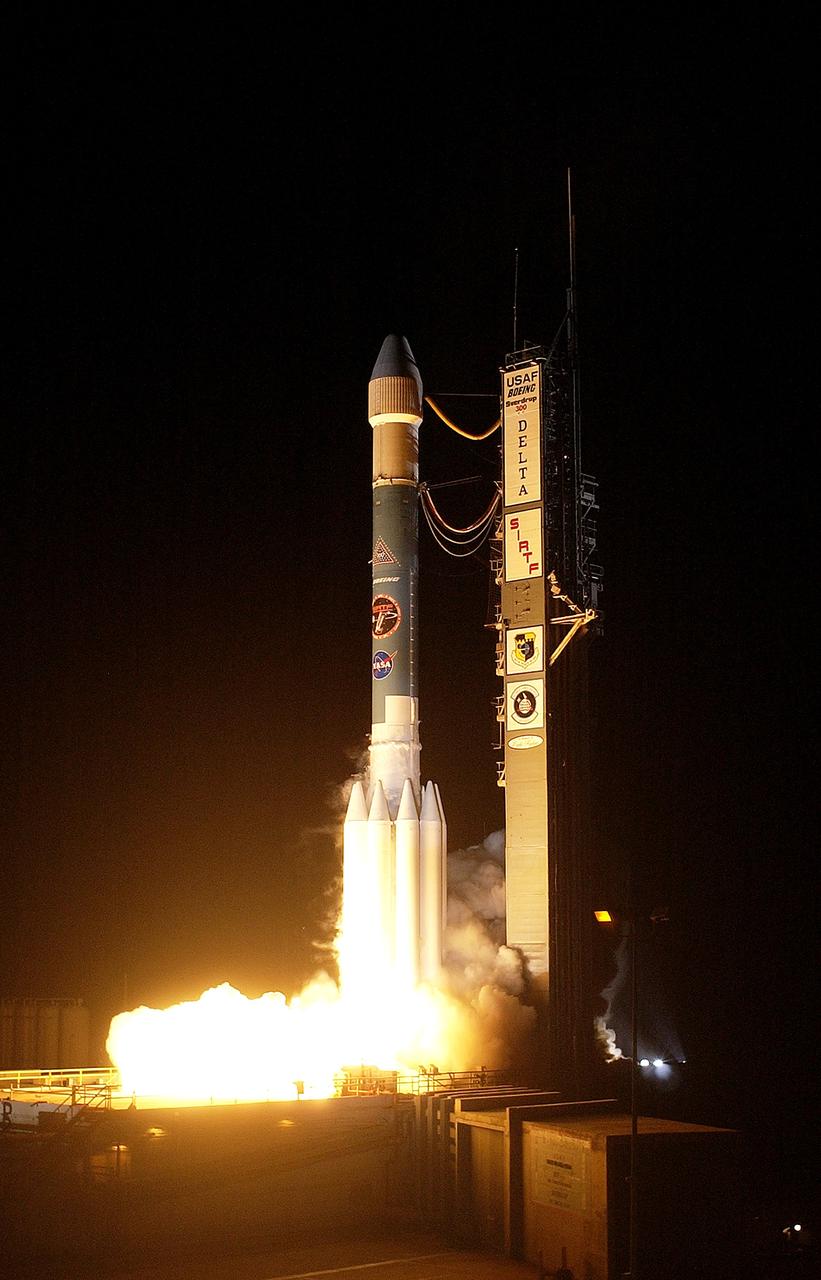
KENNEDY SPACE CENTER, FLA. - NASA's Space Infrared Telescope Facility (SIRTF) lifts off from Launch Pad 17-B, Cape Canaveral Air Force Station, on Aug. 25 at 1:35:39 a.m. EDT. SIRTF will obtain images and spectra by detecting the infrared energy, or heat, radiated by objects in space. Consisting of a 0.85-meter telescope and three cryogenically cooled science instruments, SIRTF will be the largest infrared telescope ever launched into space. It is the fourth and final element in NASA’s family of orbiting “Great Observatories.” Its highly sensitive instruments will give a unique view of the Universe and peer into regions of space that are hidden from optical telescopes.
KENNEDY SPACE CENTER, FLA. - NASA's Space Infrared Telescope Facility (SIRTF) lifts off from Launch Pad 17-B, Cape Canaveral Air Force Station, on Aug. 25 at 1:35:39 a.m. EDT. SIRTF will obtain images and spectra by detecting the infrared energy, or heat, radiated by objects in space. Consisting of a 0.85-meter telescope and three cryogenically cooled science instruments, SIRTF will be the largest infrared telescope ever launched into space. It is the fourth and final element in NASA’s family of orbiting “Great Observatories.” Its highly sensitive instruments will give a unique view of the Universe and peer into regions of space that are hidden from optical telescopes.
KENNEDY SPACE CENTER, FLA. - NASA's Space Infrared Telescope Facility (SIRTF) lifts off from Launch Pad 17-B, Cape Canaveral Air Force Station, on Aug. 25 at 1:35:39 a.m. EDT. SIRTF will obtain images and spectra by detecting the infrared energy, or heat, radiated by objects in space. Consisting of a 0.85-meter telescope and three cryogenically cooled science instruments, SIRTF will be the largest infrared telescope ever launched into space. It is the fourth and final element in NASA’s family of orbiting “Great Observatories.” Its highly sensitive instruments will give a unique view of the Universe and peer into regions of space that are hidden from optical telescopes.
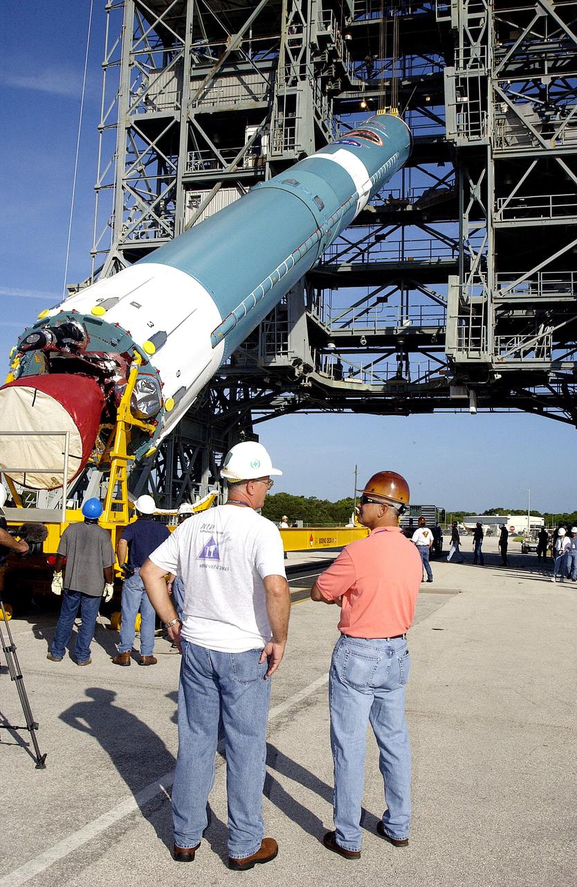
KENNEDY SPACE CENTER, FLA. - On Launch Complex 17-B, Cape Canaveral Air Force Station, the first stage of a Delta II rocket is raised off the transporter before lifting it up and moved into the mobile service tower. The rocket is being erected to launch the Space InfraRed Telescope Facility (SIRTF). Consisting of an 0.85-meter telescope and three cryogenically cooled science instruments, SIRTF is one of NASA's largest infrared telescopes to be launched. SIRTF will obtain images and spectra by detecting the infrared energy, or heat, radiated by objects in space. Most of this infrared radiation is blocked by the Earth's atmosphere and cannot be observed from the ground.
KENNEDY SPACE CENTER, FLA. - On Launch Complex 17-B, Cape Canaveral Air Force Station, the first stage of a Delta II rocket is raised off the transporter before lifting and moving it into the mobile service tower. The rocket is being erected to launch the Space InfraRed Telescope Facility (SIRTF). Consisting of an 0.85-meter telescope and three cryogenically cooled science instruments, SIRTF is one of NASA's largest infrared telescopes to be launched. SIRTF will obtain images and spectra by detecting the infrared energy, or heat, radiated by objects in space. Most of this infrared radiation is blocked by the Earth's atmosphere and cannot be observed from the ground.
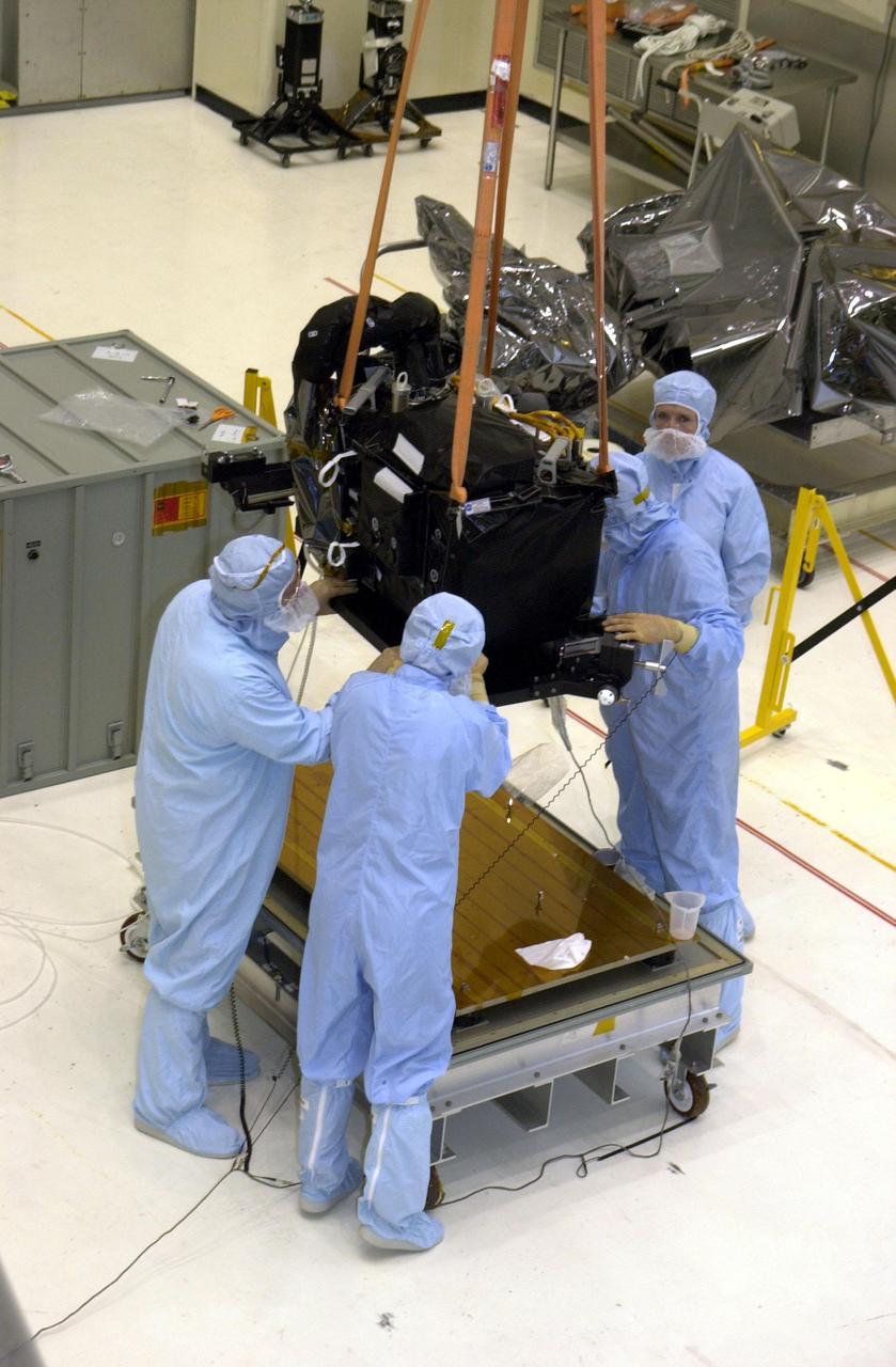
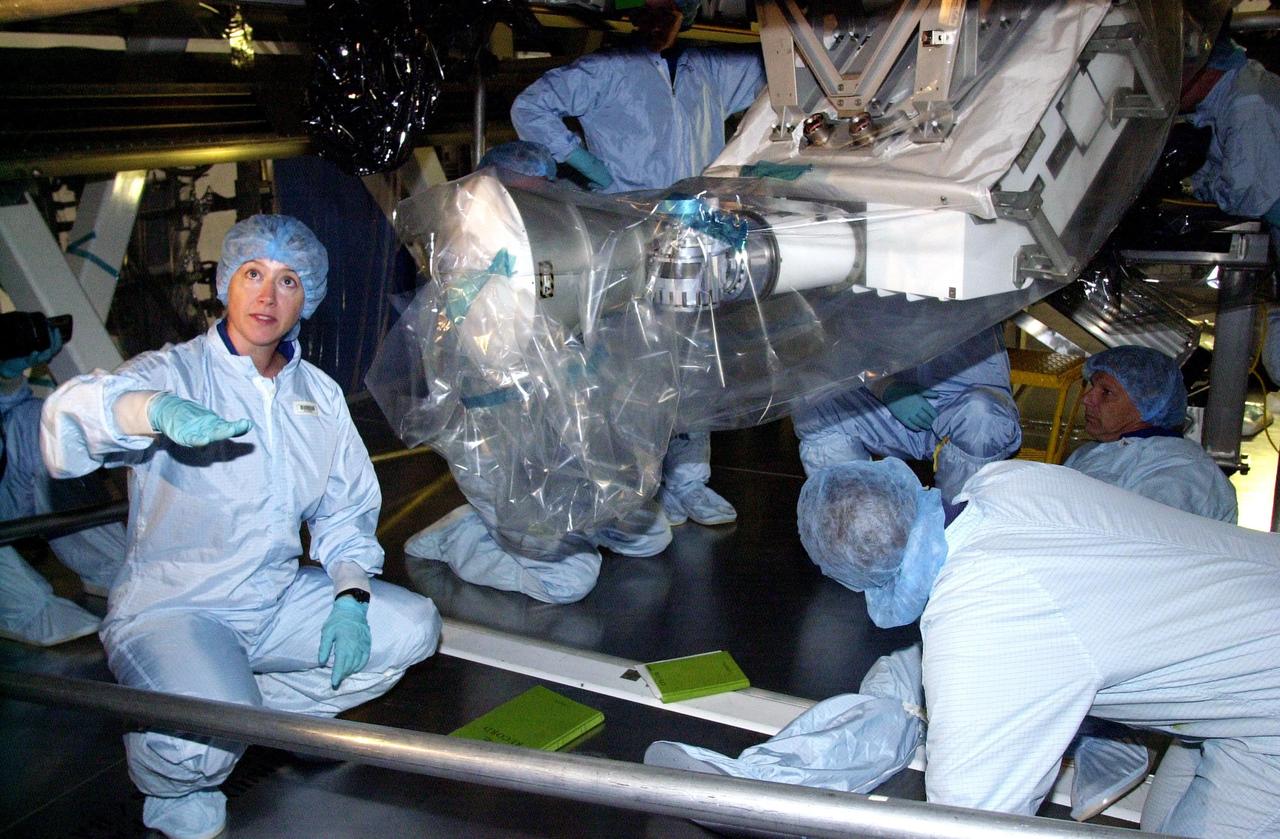
KENNEDY SPACE CENTER, FLA. - A crane in the Vertical Processing Facility lifts the Near Infrared Camera and Multi-Object Spectrometer (NICMOS) Cooling System off the workstand. NICMOS II is part of the payload on mission STS-109, the Hubble Servicing Telescope Mission. It is a new experimental cooling system consisting of a compressor and tiny turbines. With the experimental cryogenic system, NASA hopes to re-cool the infrared detectors to below -315 degrees F (-193 degrees Celsius). NICMOS II was previously tested aboard STS-95 in 1998. It could extend the life of the Hubble Space Telescope by several years. Astronauts aboard Columbia on mission STS-109 will be replacing the original NICMOS with the newer version. Launch of mission STS-109 is scheduled for Feb. 28, 2002
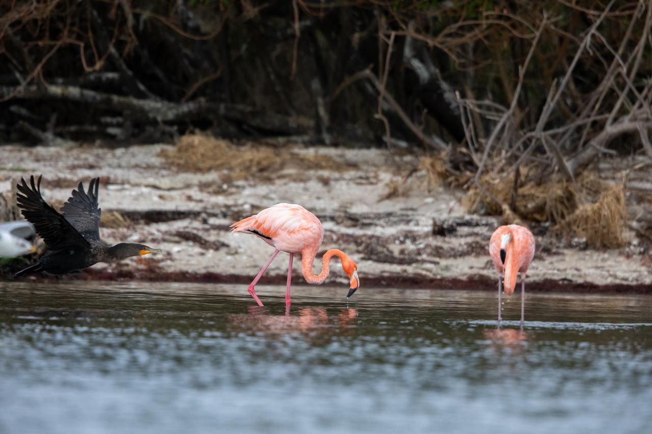
American Flamingos cool off in the Indian River at Haulover Canal on Merritt Island on Thursday, Jan. 11, 2024. The American Flamingos are more common in Mexico and Cuba but the winds from Hurricane Idalia relocated them to Florida in September 2023. Kennedy Space Center in Florida shares a border with the Merritt Island National Wildlife Refuge where more than 310 species of birds inhabit the refuge.
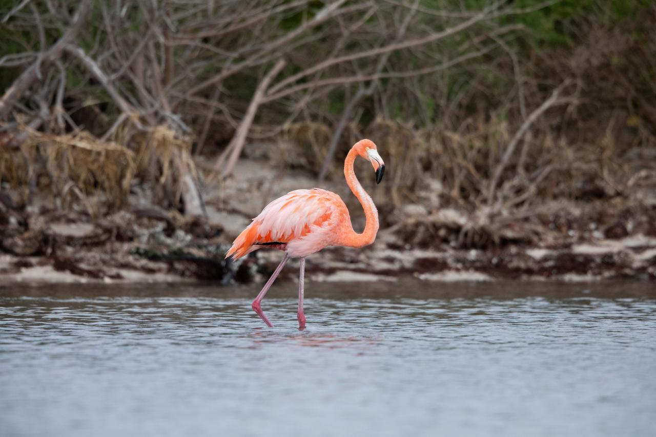
An American Flamingo cools off in the Indian River at Haulover Canal on Merritt Island on Thursday, Jan. 11, 2024. The American Flamingos are more common in Mexico and Cuba but the winds from Hurricane Idalia relocated them to Florida in September 2023. Kennedy Space Center in Florida shares a border with the Merritt Island National Wildlife Refuge where more than 310 species of birds inhabit the refuge.
KENNEDY SPACE CENTER, FLA. - - Viewed from across the cooling water pond is the mobile service tower with the first stage of the Boeing Delta II rocket inside. The Delta II is the launch vehicle for the MESSENGER spacecraft, scheduled to lift off Aug. 2, bound for Mercury. The spacecraft is expected to reach orbit around Mercury in March 2011. MESSENGER was built for NASA by the Johns Hopkins University Applied Physics Laboratory in Laurel, Md.
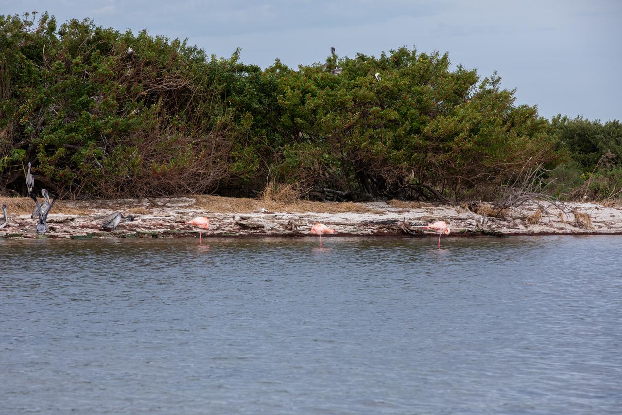
Three American Flamingos cool off in the Indian River at Haulover Canal on Merritt Island on Thursday, Jan. 11, 2024. The American Flamingos are more common in Mexico and Cuba but the winds from Hurricane Idalia relocated them to Florida in September 2023. Kennedy Space Center in Florida shares a border with the Merritt Island National Wildlife Refuge where more than 310 species of birds inhabit the refuge.

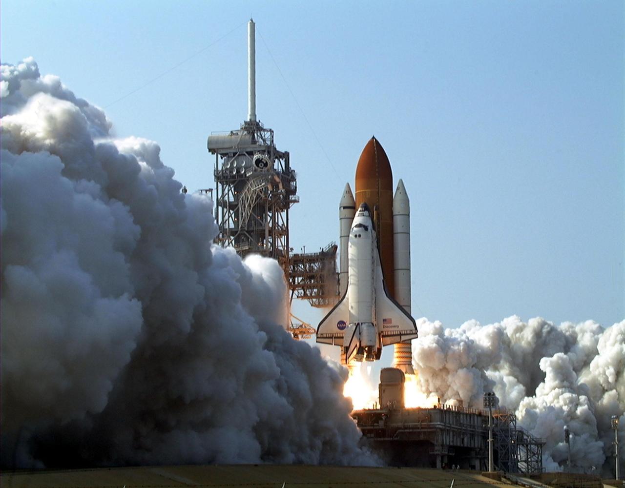
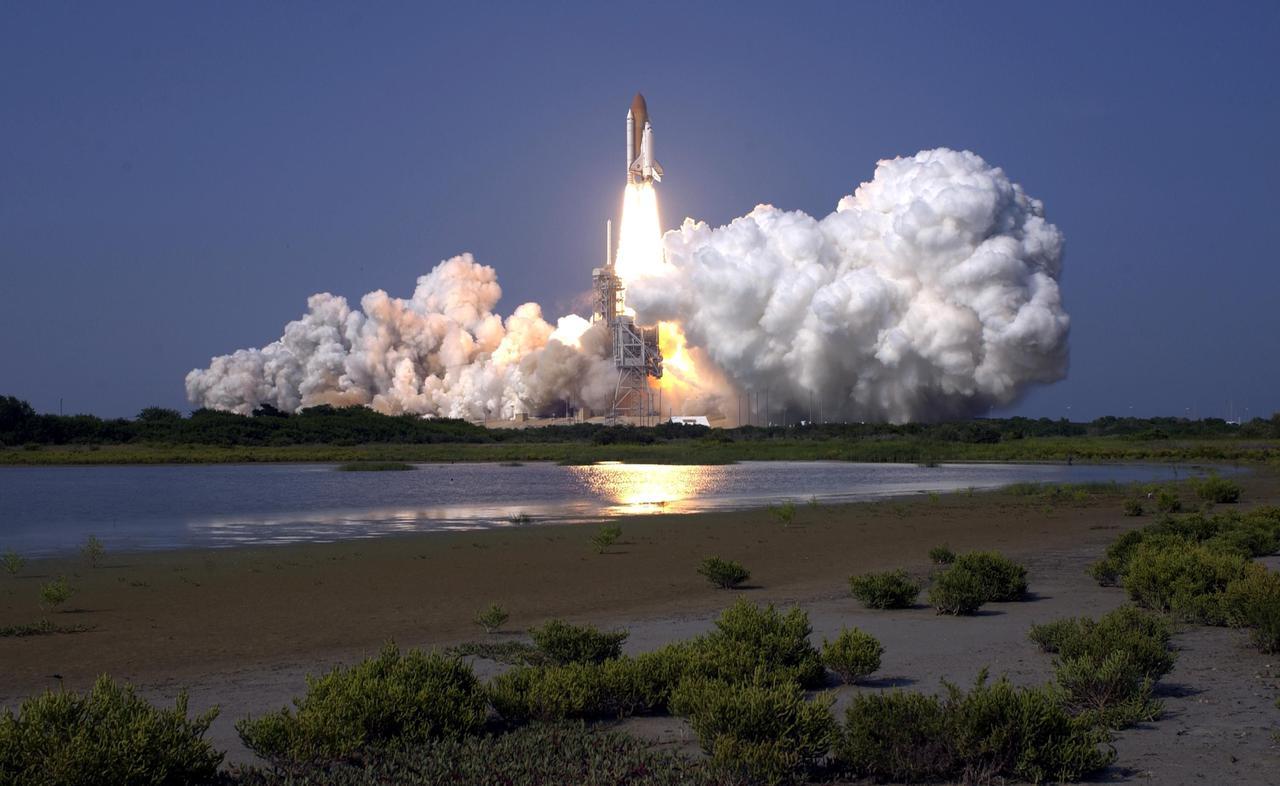
KENNEDY SPACE CENTER, Fla. -- Smoke and steam roll over the ground as Space Shuttle Discovery lifts off on mission STS-105. Liftoff occurred on time at 5:10:14 p.m. EDT. Besides the Shuttle crew of four, Discovery carries the Expedition Three crew who will replace Expedition Two on the International Space Station. The mission includes the third flight of an Italian-built Multi-Purpose Logistics Module delivering additional scientific racks, equipment and supplies for the Space Station, and two spacewalks. Part of the payload is the Early Ammonia Servicer (EAS) tank, which will be attached to the Station during the spacewalks. The EAS will be installed on the P6 truss, which holds the Station’s giant U.S. solar arrays, batteries and the cooling radiators. The EAS contains spare ammonia for the Station’s cooling system. The three-member Expedition Two crew will be returning to Earth aboard Discovery after a five-month stay on the Station
KENNEDY SPACE CENTER, Fla. -- Smoke and steam roll over the ground as Space Shuttle Discovery lifts off on mission STS-105. Liftoff occurred on time at 5:10:14 p.m. EDT. Besides the Shuttle crew of four, Discovery carries the Expedition Three crew who will replace Expedition Two on the International Space Station. The mission includes the third flight of an Italian-built Multi-Purpose Logistics Module delivering additional scientific racks, equipment and supplies for the Space Station, and two spacewalks. Part of the payload is the Early Ammonia Servicer (EAS) tank, which will be attached to the Station during the spacewalks. The EAS will be installed on the P6 truss, which holds the Station’s giant U.S. solar arrays, batteries and the cooling radiators. The EAS contains spare ammonia for the Station’s cooling system. The three-member Expedition Two crew will be returning to Earth aboard Discovery after a five-month stay on the Station
STS-109 Astronaut Michael J. Massimino, mission specialist, perched on the Shuttle's robotic arm, is preparing to install the Electronic Support Module (ESM) in the aft shroud of the Hubble Space telescope (HST), with the assistance of astronaut James H. Newman (out of frame). The module will support a new experimental cooling system to be installed during the next day's fifth and final space walk of the mission. That cooling system is designed to bring the telescope's Near-Infrared Camera and Multi Spectrometer (NICMOS) back to life the which had been dormant since January 1999 when its original coolant ran out. The Space Shuttle Columbia STS-109 mission lifted off March 1, 2002 with goals of repairing and upgrading the Hubble Space Telescope (HST). The Marshall Space Flight Center in Huntsville, Alabama had the responsibility for the design, development, and construction of the HST, which is the most powerful and sophisticated telescope ever built. In addition to the installation of the experimental cooling system for the Hubble's Near-Infrared Camera and NICMOS, STS-109 upgrades to the HST included replacement of the solar array panels, replacement of the power control unit (PCU), and replacement of the Faint Object Camera (FOC) with a new advanced camera for Surveys (ACS). Lasting 10 days, 22 hours, and 11 minutes, the STS-109 mission was the 108th flight overall in NASA's Space Shuttle Program.
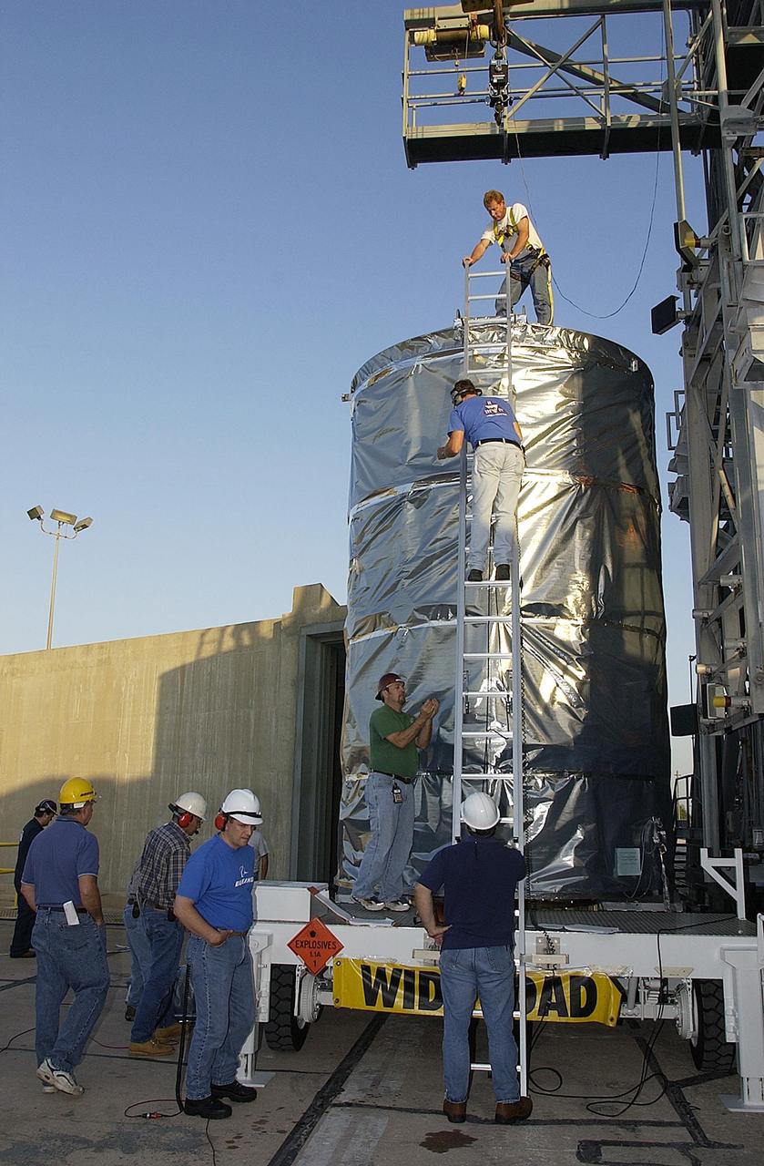
KENNEDY SPACE CENTER, FLA. -- The payload canister with the Space Infrared Telescope Facility (SIRTF) inside is lifted off the transporter on Launch Complex 17-B, Cape Canaveral Air Force Station. SIRTF will be mated with the Delta II launch vehicle in the tower. SIRTF will obtain images and spectra by detecting the infrared energy, or heat, radiated by objects in space. Most of this infrared radiation is blocked by the Earth's atmosphere and cannot be observed from the ground. Consisting of an 0.85-meter telescope and three cryogenically cooled science instruments, SIRTF is one of NASA's largest infrared telescopes to be launched.
KENNEDY SPACE CENTER, FLA. - STS-112 Pilot Pamela Melroy signals to someone off camera while behind her other crew members look over the S1 Integrated Truss Structure, part of the payload for the mission to the International Space Station. The S1 truss is the first starboard (right-side) truss segment, whose main job is providing structural support for the orbiting research facility's radiator panels that cool the Space Station's complex power system. The S1 truss segment also will house communications systems, external experiment positions and other subsystems. The S1 truss will be attached to the S0 truss. Launch of STS-112 is scheduled for Aug. 22, 2002
NASA's Space Infrared Telescope Facility (SIRTF) lifts off from Launch Pad 17-B, Cape Canaveral Air Force Station, on Aug. 25 at 1:35:39 a.m. EDT. SIRTF will obtain images and spectra by detecting the infrared energy, or heat, radiated by objects in space. Consisting of a 0.85-meter telescope and three cryogenically cooled science instruments, SIRTF will be the largest infrared telescope ever launched into space. It is the fourth and final element in NASA’s family of orbiting “Great Observatories.” Its highly sensitive instruments will give a unique view of the Universe and peer into regions of space that are hidden from optical telescopes.
NASA's Space Infrared Telescope Facility (SIRTF) lifts off from Launch Pad 17-B, Cape Canaveral Air Force Station, on Aug. 25 at 1:35:39 a.m. EDT. SIRTF will obtain images and spectra by detecting the infrared energy, or heat, radiated by objects in space. Consisting of a 0.85-meter telescope and three cryogenically cooled science instruments, SIRTF will be the largest infrared telescope ever launched into space. It is the fourth and final element in NASA’s family of orbiting “Great Observatories.” Its highly sensitive instruments will give a unique view of the Universe and peer into regions of space that are hidden from optical telescopes.
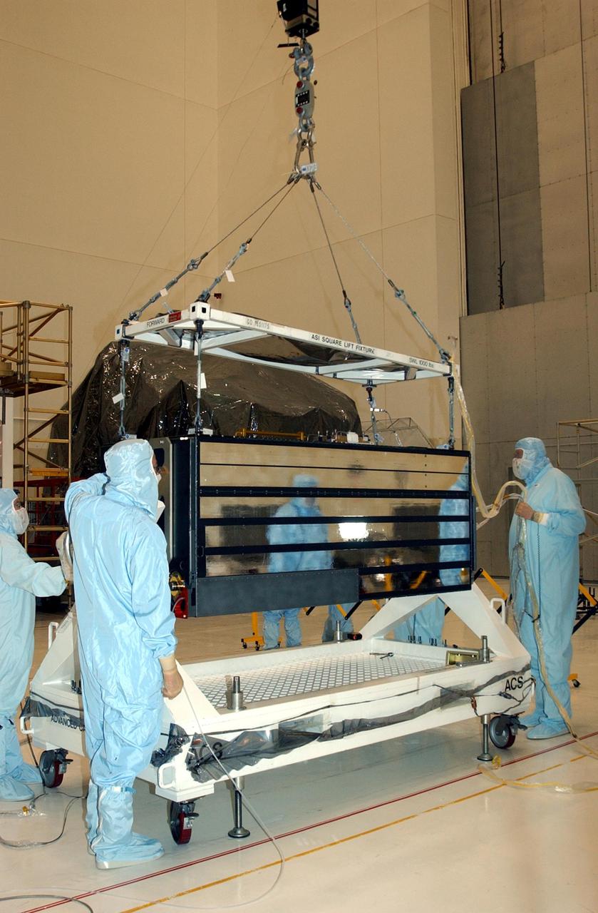
KENNEDY SPACE CENTER, FLA. -- In the Vertical Processing Facility, workers watch while an overhead crane lifts the Advanced Camera for Surveys (ACS) off the stand. The ACS is part of the payload on the Hubble Space Telescope Servicing Mission, STS-109. The goal of the mission is to service the HST, replacing Solar Array 2 with Solar Array 3, replacing the Power Control Unit, removing the Faint Object Camera and installing the ACS, installing the Near Infrared Camera and Multi-Object Spectrometer (NICMOS) Cooling System, and installing New Outer Blanket Layer insulation. Mission STS-109 is scheduled for launch no earlier than Feb. 21, 2002
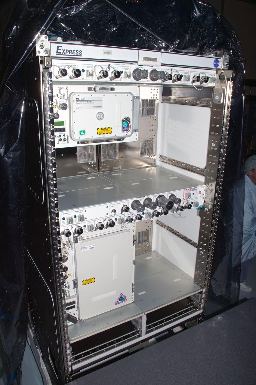
CAPE CANAVERAL, Fla. – This photo shows the crew galley that will be delivered to the International Space Station aboard space shuttle Endeavour on the STS-126 mission. It is designed to make use of the top half of EXPRESS Rack 6 for power, cooling and water. It will consist of one potable water dispenser, one food warmer, and one MERLIN refrigerator. Once on orbit, the galley will be transferred to the U.S. Lab. Endeavour and its crew of seven are scheduled to lift off at 7:55 p.m. Nov. 14 for the 15-day STS-126 mission. Photo credit: NASA
On Launch Complex 17-B, Cape Canaveral Air Force Station, the second stage of the Delta II Heavy rocket is raised off its transporter before being lifted up the mobile service tower and mated to the first stage. The rocket will launch the Space Infrared Telescope Facility (SIRTF), currently scheduled for mid-August. SIRTF consists of three cryogenically cooled science instruments and an 0.85-meter telescope, and is one of NASA's largest infrared telescopes to be launched. SIRTF will obtain images and spectra by detecting the infrared energy, or heat, radiated by objects in space. Most of this infrared radiation is blocked by the Earth's atmosphere and cannot be observed from the ground.
NASA's Space Infrared Telescope Facility (SIRTF) is moments away from lift off from Launch Pad 17-B, Cape Canaveral Air Force Station, on Aug. 25. Launch is scheduled for 1:35:39 a.m. EDT. SIRTF will obtain images and spectra by detecting the infrared energy, or heat, radiated by objects in space. Consisting of a 0.85-meter telescope and three cryogenically cooled science instruments, SIRTF will be the largest infrared telescope ever launched into space. It is the fourth and final element in NASA’s family of orbiting “Great Observatories.” Its highly sensitive instruments will give a unique view of the Universe and peer into regions of space that are hidden from optical telescopes.
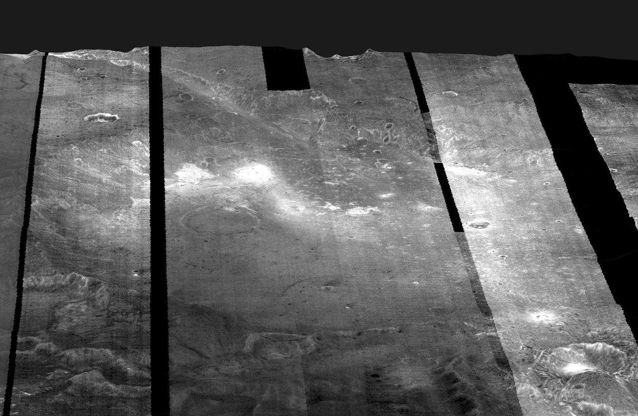
Images from NASA's Mars Odyssey spacecraft were used to create this mosaic of nighttime infrared images of Gusev Crater, which has been draped over topography data obtained by NASA Mars Global Surveyor. Variations in nighttime temperatures are due to differences in the abundance of rocky materials that retain their heat at night and stay relatively warm (bright). Fine grained dust and sand (dark) cools off more rapidly at night. This image mosaic covers an area approximately 180 kilometers (110 miles) on each side centered near 14 degrees S, 175 degrees E, looking toward the south in this simulated view. http://photojournal.jpl.nasa.gov/catalog/PIA04261

KENNEDY SPACE CENTER, FLA. -- In the Vertical Processing Facility, workers watch while an overhead crane lifts the Advanced Camera for Surveys (ACS) off the stand. The ACS is part of the payload on the Hubble Space Telescope Servicing Mission, STS-109. The goal of the mission is to service the HST, replacing Solar Array 2 with Solar Array 3, replacing the Power Control Unit, removing the Faint Object Camera and installing the ACS, installing the Near Infrared Camera and Multi-Object Spectrometer (NICMOS) Cooling System, and installing New Outer Blanket Layer insulation. Mission STS-109 is scheduled for launch no earlier than Feb. 21, 2002
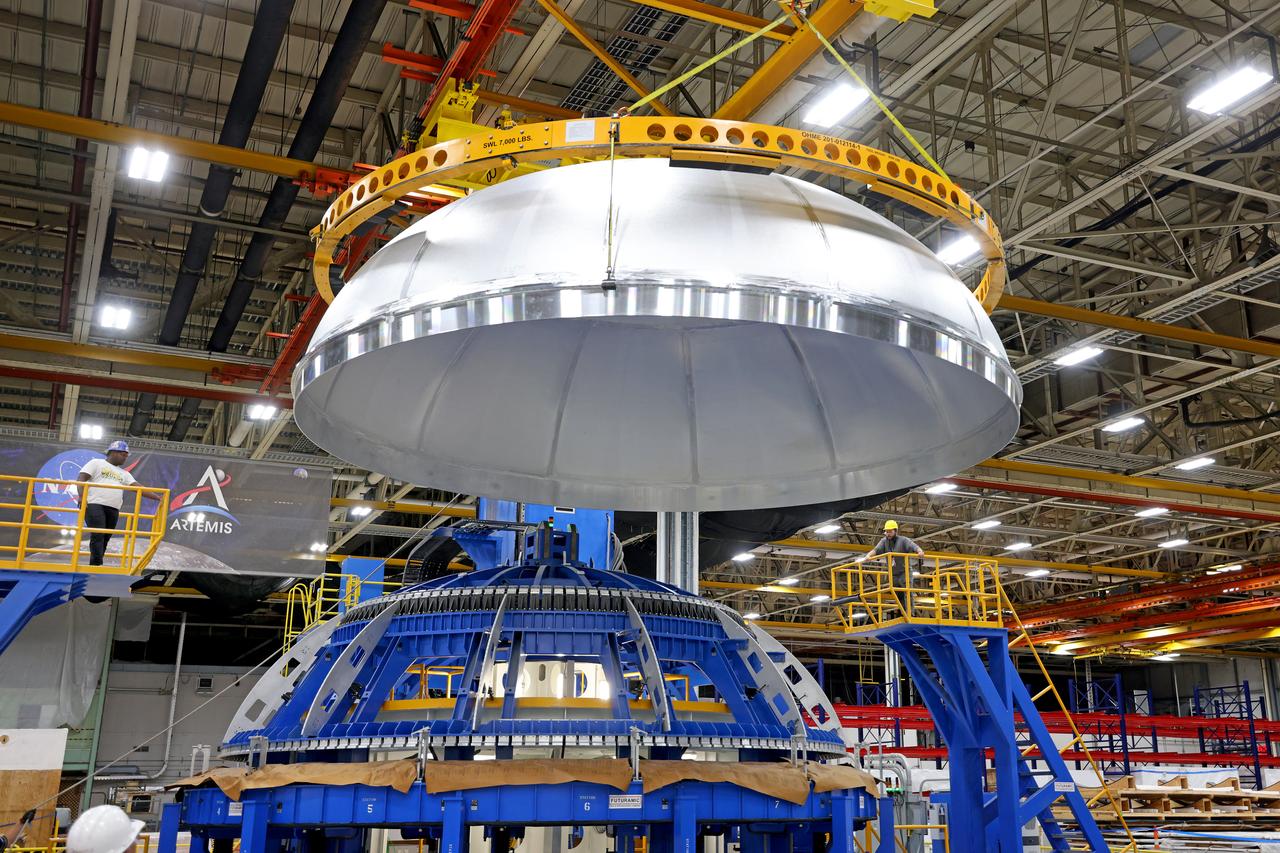
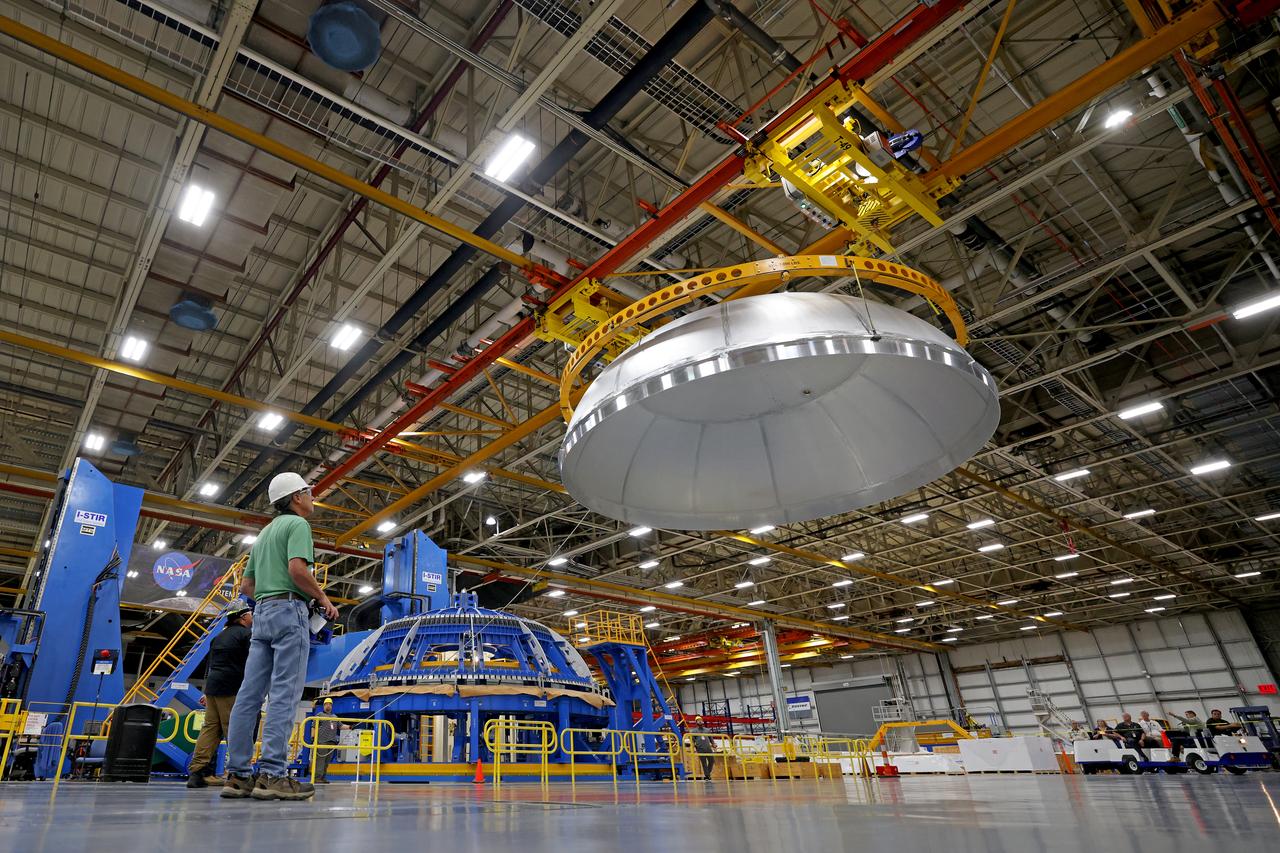
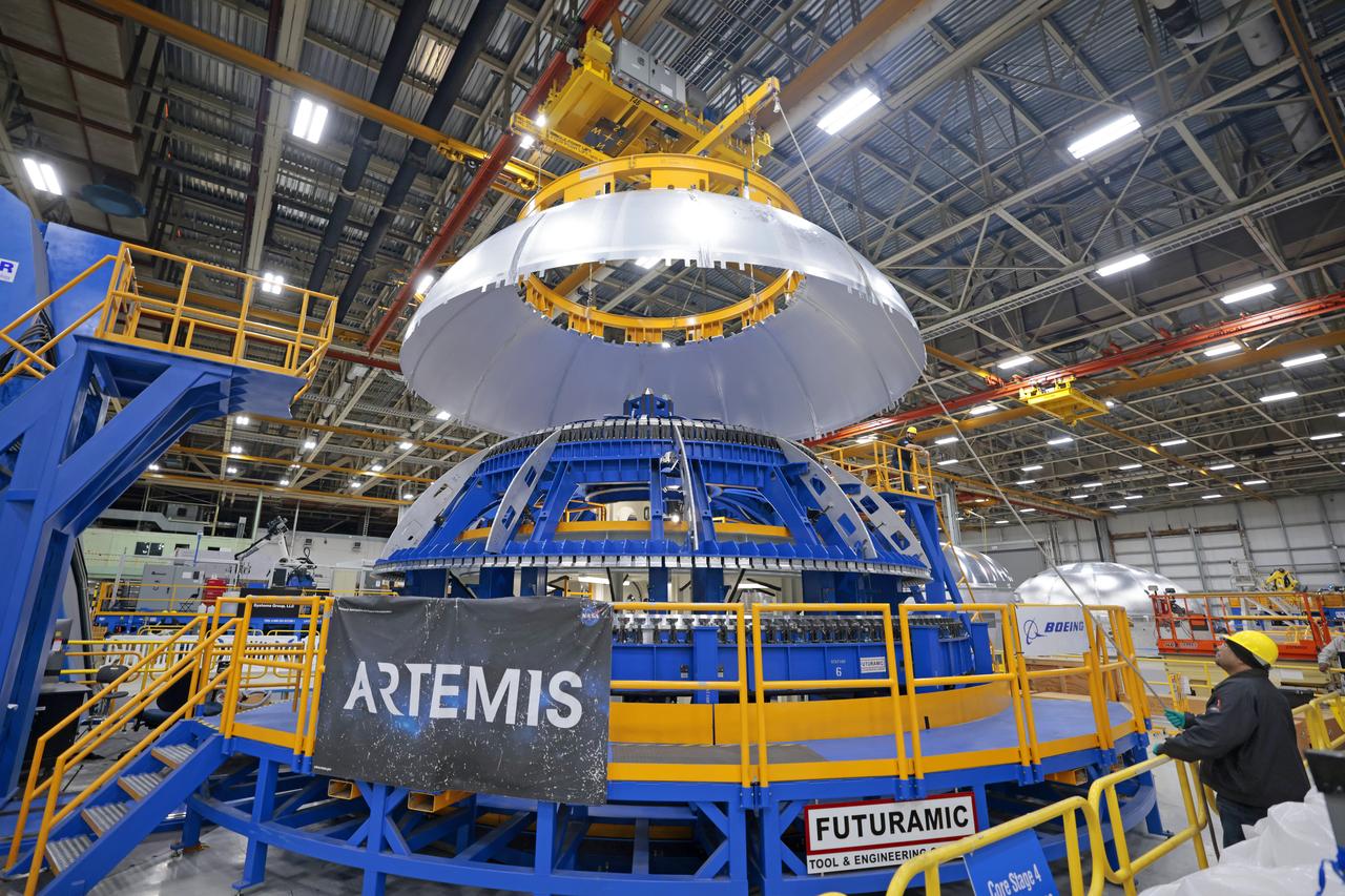
Teams completed welding of the liquid oxygen dome for the core stage of a future SLS (Space Launch System) rocket at NASA’s Michoud Assembly Facility in New Orleans. The dome, which will cap off the forward end of the liquid oxygen tank, was lifted off of the robotic weld tool and moved to an assembly area for the next phase of production. Later, crews will add the forward dome to join the two barrels and the aft dome to complete the liquid oxygen tank. The flight hardware will be used for Artemis IV, the first flight of SLS in its Block 1B configuration. The SLS core stage liquid oxygen tank holds 196,000 gallons of super-cooled liquid propellant. The SLS core stage is made up of five unique elements: the forward skirt, liquid oxygen tank, intertank, liquid hydrogen tank, and the engine section. The liquid oxygen and the liquid hydrogen tanks will provide propellant to the four RS-25 engines to produce more than two million pounds of thrust to help launch NASA’s Orion spacecraft, astronauts, and supplies beyond Earth’s orbit to the Moon. Image credit: NASA/Michael DeMocker
Teams completed welding of the liquid oxygen dome for the core stage of a future SLS (Space Launch System) rocket at NASA’s Michoud Assembly Facility in New Orleans. The dome, which will cap off the forward end of the liquid oxygen tank, was lifted off of the robotic weld tool and moved to an assembly area for the next phase of production. Later, crews will add the forward dome to join the two barrels and the aft dome to complete the liquid oxygen tank. The flight hardware will be used for Artemis IV, the first flight of SLS in its Block 1B configuration. The SLS core stage liquid oxygen tank holds 196,000 gallons of super-cooled liquid propellant. The SLS core stage is made up of five unique elements: the forward skirt, liquid oxygen tank, intertank, liquid hydrogen tank, and the engine section. The liquid oxygen and the liquid hydrogen tanks will provide propellant to the four RS-25 engines to produce more than two million pounds of thrust to help launch NASA’s Orion spacecraft, astronauts, and supplies beyond Earth’s orbit to the Moon. Image credit: NASA/Michael DeMocker

Teams completed welding of the liquid oxygen dome for the core stage of a future SLS (Space Launch System) rocket at NASA’s Michoud Assembly Facility in New Orleans. The dome, which will cap off the forward end of the liquid oxygen tank, was lifted off of the robotic weld tool and moved to an assembly area for the next phase of production. Later, crews will add the forward dome to join the two barrels and the aft dome to complete the liquid oxygen tank. The flight hardware will be used for Artemis IV, the first flight of SLS in its Block 1B configuration. The SLS core stage liquid oxygen tank holds 196,000 gallons of super-cooled liquid propellant. The SLS core stage is made up of five unique elements: the forward skirt, liquid oxygen tank, intertank, liquid hydrogen tank, and the engine section. The liquid oxygen and the liquid hydrogen tanks will provide propellant to the four RS-25 engines to produce more than two million pounds of thrust to help launch NASA’s Orion spacecraft, astronauts, and supplies beyond Earth’s orbit to the Moon. Image credit: NASA/Michael DeMocker

Teams completed welding of the liquid oxygen dome for the core stage of a future SLS (Space Launch System) rocket at NASA’s Michoud Assembly Facility in New Orleans. The dome, which will cap off the forward end of the liquid oxygen tank, was lifted off of the robotic weld tool and moved to an assembly area for the next phase of production. Later, crews will add the forward dome to join the two barrels and the aft dome to complete the liquid oxygen tank. The flight hardware will be used for Artemis IV, the first flight of SLS in its Block 1B configuration. The SLS core stage liquid oxygen tank holds 196,000 gallons of super-cooled liquid propellant. The SLS core stage is made up of five unique elements: the forward skirt, liquid oxygen tank, intertank, liquid hydrogen tank, and the engine section. The liquid oxygen and the liquid hydrogen tanks will provide propellant to the four RS-25 engines to produce more than two million pounds of thrust to help launch NASA’s Orion spacecraft, astronauts, and supplies beyond Earth’s orbit to the Moon. Image credit: NASA/Michael DeMocker
KENNEDY SPACE CENTER, Fla. -- Expedition Three cosmonaut Vladimir Dezhurov is ready for the second launch attempt of mission STS-105 after a 24-hour weather delay. Launch countdown activities for the 12-day mission were called off at about 5:12 p.m. Aug. 9 during the T-9 minute hold due to the high potential for lightning, a thick cloud cover and the potential for showers. Launch is currently scheduled for 5:15 p.m. EDT Aug. 10. Highlighting the mission will be the rotation of the International Space Station crew, the third flight of an Italian-built Multi-Purpose Logistics Module delivering additional scientific racks, equipment and supplies for the Space Station, and two spacewalks. Included in the payload is the Early Ammonia Servicer (EAS) tank, which will be attached to the Station during the spacewalks. The EAS will be installed on the P6 truss, which holds the Station’s giant U.S. solar arrays, batteries and the cooling radiators. The EAS contains spare ammonia for the Station’s cooling system. The three-member Expedition Two crew will be returning to Earth aboard Discovery after a five-month stay on the Station
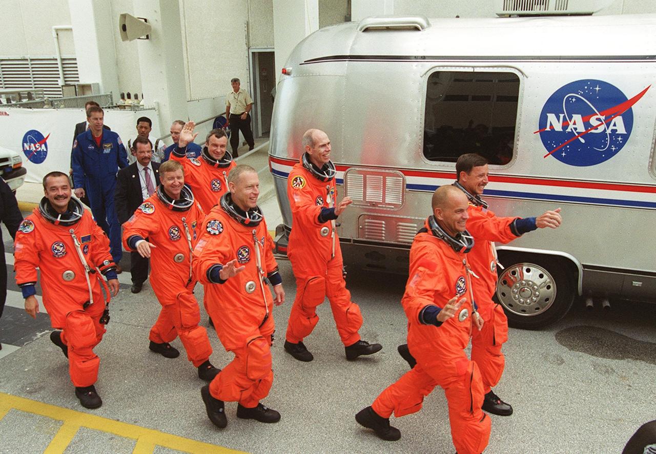
KENNEDY SPACE CENTER, Fla. -- Waving to onlookers, the STS-105 and Expedition Three (E3) crews head to the Astrovan that will take them to Launch Pad 39A for a second attempt at launch on mission STS-105. From the left are E3 cosmonaut Mikhail Tyurin, Commander Frank Culbertson and cosmonaut Vladimir Dezhurov; STS-105 Mission Specialists Patrick Forrester and Daniel Barry, Pilot Rick Sturckow and Commander Scott Horowitz. . Launch countdown activities for the 12-day mission were called off at about 5:12 p.m. Aug. 9 during the T-9 minute hold due to the high potential for lightning, a thick cloud cover and the potential for showers. Launch is currently scheduled for 5:15 p.m. EDT Aug. 10. Highlighting the mission will be the rotation of the International Space Station crew, the third flight of an Italian-built Multi-Purpose Logistics Module delivering additional scientific racks, equipment and supplies for the Space Station, and two spacewalks. Included in the payload is the Early Ammonia Servicer (EAS) tank, which will be attached to the Station during the spacewalks. The EAS will be installed on the P6 truss, which holds the Station’s giant U.S. solar arrays, batteries and the cooling radiators. The EAS contains spare ammonia for the Station’s cooling system. The three-member Expedition Two crew will be returning to Earth aboard Discovery after a five-month stay on the Station

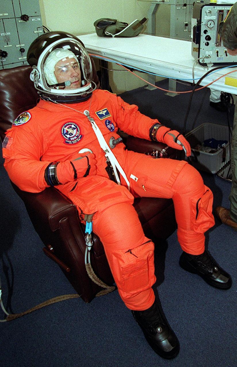
KENNEDY SPACE CENTER, Fla. -- STS-105 Commander Scott Horowitz is helped with his launch and entry suit for the second launch attempt after a 24-hour weather delay. Launch countdown activities for the 12-day mission were called off at about 5:12 p.m. Aug. 9 during the T-9 minute hold due to the high potential for lightning, a thick cloud cover and the potential for showers. Launch is currently scheduled for 5:15 p.m. EDT Aug. 10. Highlighting the mission will be the rotation of the International Space Station crew, the third flight of an Italian-built Multi-Purpose Logistics Module delivering additional scientific racks, equipment and supplies for the Space Station, and two spacewalks. Included in the payload is the Early Ammonia Servicer (EAS) tank, which will be attached to the Station during the spacewalks. The EAS will be installed on the P6 truss, which holds the Station’s giant U.S. solar arrays, batteries and the cooling radiators. The EAS contains spare ammonia for the Station’s cooling system. The three-member Expedition Two crew will be returning to Earth aboard Discovery after a five-month stay on the Station
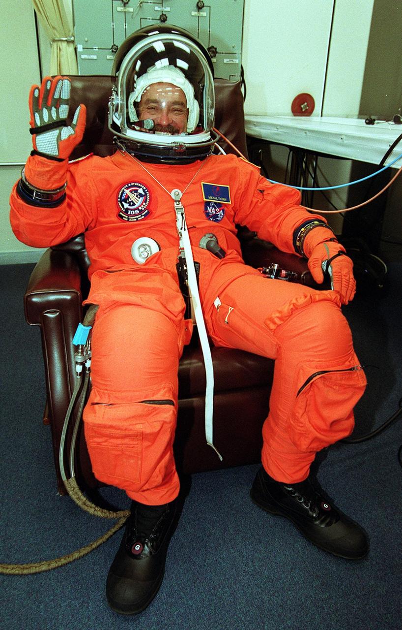
KENNEDY SPACE CENTER, Fla. -- Expedition Three cosmonaut Mikhail Tyurin is eager for the second launch attempt of mission STS-105 after a 24-hour weather delay. This is Tyurin’s first space flight. Launch countdown activities for the 12-day mission were called off at about 5:12 p.m. Aug. 9 during the T-9 minute hold due to the high potential for lightning, a thick cloud cover and the potential for showers. Launch is currently scheduled for 5:15 p.m. EDT Aug. 10. Highlighting the mission will be the rotation of the International Space Station crew, the third flight of an Italian-built Multi-Purpose Logistics Module delivering additional scientific racks, equipment and supplies for the Space Station, and two spacewalks. Included in the payload is the Early Ammonia Servicer (EAS) tank, which will be attached to the Station during the spacewalks. The EAS will be installed on the P6 truss, which holds the Station’s giant U.S. solar arrays, batteries and the cooling radiators. The EAS contains spare ammonia for the Station’s cooling system. The three-member Expedition Two crew will be returning to Earth aboard Discovery after a five-month stay on the Station
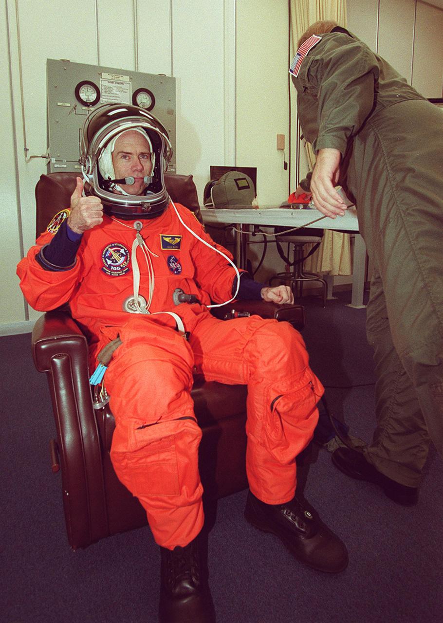
KENNEDY SPACE CENTER, Fla. -- STS-105 Mission Specialist Daniel Barry is set to go on the second launch attempt after a 24-hour weather delay. Launch countdown activities for the 12-day mission were called off at about 5:12 p.m. Aug. 9 during the T-9 minute hold due to the high potential for lightning, a thick cloud cover and the potential for showers. Launch is currently scheduled for 5:15 p.m. EDT Aug. 10. Highlighting the mission will be the rotation of the International Space Station crew, the third flight of an Italian-built Multi-Purpose Logistics Module delivering additional scientific racks, equipment and supplies for the Space Station, and two spacewalks. Included in the payload is the Early Ammonia Servicer (EAS) tank, which will be attached to the Station during the spacewalks. The EAS will be installed on the P6 truss, which holds the Station’s giant U.S. solar arrays, batteries and the cooling radiators. The EAS contains spare ammonia for the Station’s cooling system. The three-member Expedition Two crew will be returning to Earth aboard Discovery after a five-month stay on the Station
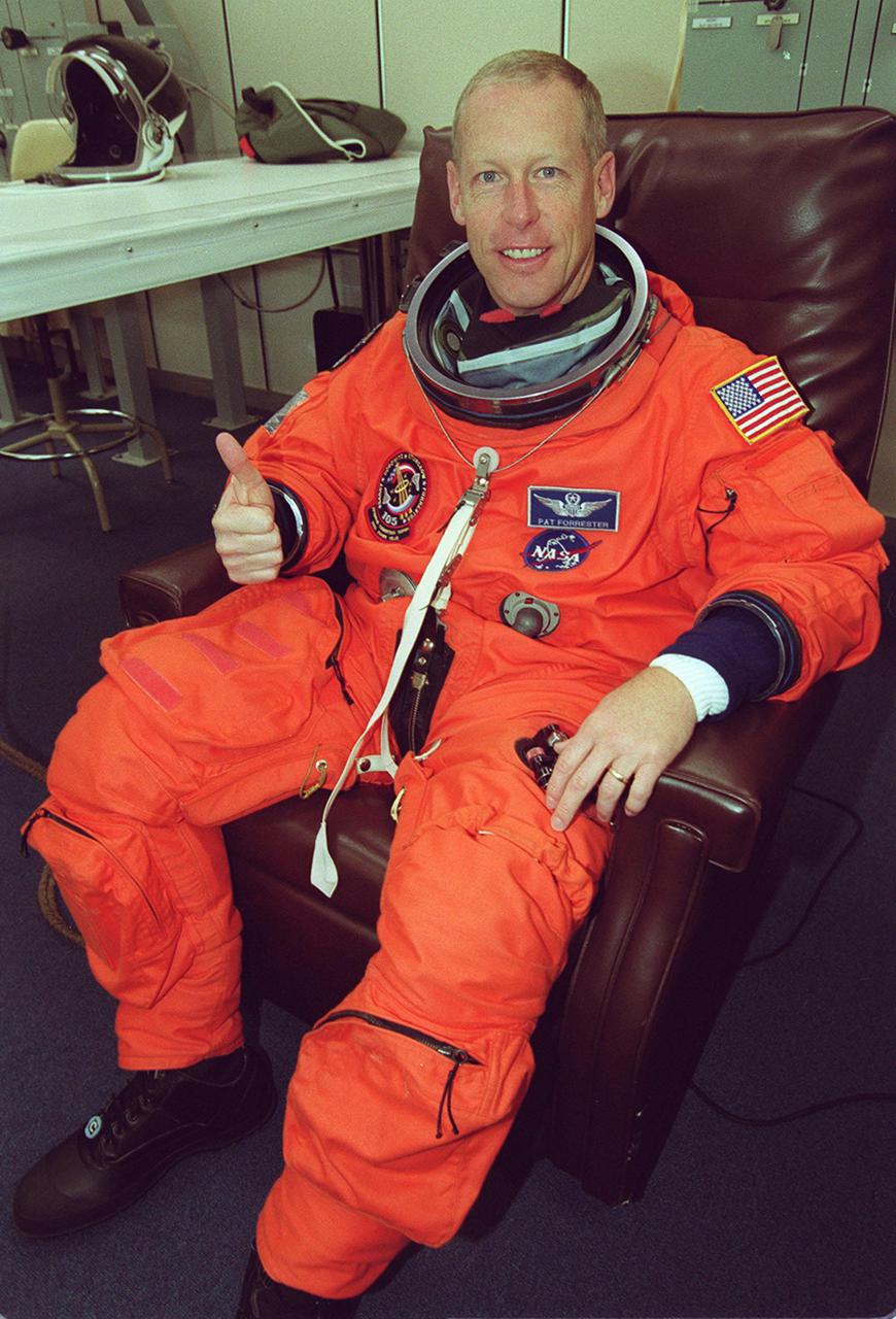
KENNEDY SPACE CENTER, Fla. -- STS-105 Mission Specialist Patrick Forrester is eager for the second launch attempt on mission STS-105 after a 24-hour weather delay. Launch countdown activities for the 12-day mission were called off at about 5:12 p.m. Aug. 9 during the T-9 minute hold due to the high potential for lightning, a thick cloud cover and the potential for showers. Launch is currently scheduled for 5:15 p.m. EDT Aug. 10. Highlighting the mission will be the rotation of the International Space Station crew, the third flight of an Italian-built Multi-Purpose Logistics Module delivering additional scientific racks, equipment and supplies for the Space Station, and two spacewalks. Included in the payload is the Early Ammonia Servicer (EAS) tank, which will be attached to the Station during the spacewalks. The EAS will be installed on the P6 truss, which holds the Station’s giant U.S. solar arrays, batteries and the cooling radiators. The EAS contains spare ammonia for the Station’s cooling system. The three-member Expedition Two crew will be returning to Earth aboard Discovery after a five-month stay on the Station
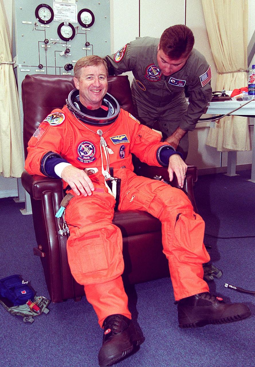
KENNEDY SPACE CENTER, Fla. -- Expedition Three Commander Frank Culbertson is helped with his launch and entry suit for the second launch attempt after a 24-hour weather delay. Launch countdown activities for the 12-day mission were called off at about 5:12 p.m. Aug. 9 during the T-9 minute hold due to the high potential for lightning, a thick cloud cover and the potential for showers. Launch is currently scheduled for 5:15 p.m. EDT Aug. 10. Highlighting the mission will be the rotation of the International Space Station crew, the third flight of an Italian-built Multi-Purpose Logistics Module delivering additional scientific racks, equipment and supplies for the Space Station, and two spacewalks. Included in the payload is the Early Ammonia Servicer (EAS) tank, which will be attached to the Station during the spacewalks. The EAS will be installed on the P6 truss, which holds the Station’s giant U.S. solar arrays, batteries and the cooling radiators. The EAS contains spare ammonia for the Station’s cooling system. The three-member Expedition Two crew will be returning to Earth aboard Discovery after a five-month stay on the Station
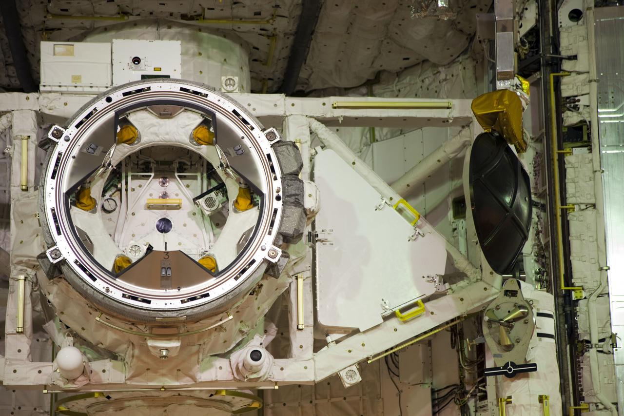
CAPE CANAVERAL, Fla. -- At Launch Pad 39A at NASA's Kennedy Space Center in Florida, work is under way to close space shuttle Atlantis' payload bay doors around the Raffaello multi-purpose logistics module (MPLM) payload for Atlantis' STS-135 mission to the International Space Station. Seen here is the airlock which is sized to accommodate two fully suited flight crew members simultaneously. Support functions include airlock depressurization and repressurization, extravehicular activity equipment recharge, liquid-cooled garment water cooling, spacesuit equipment checkout, and communications. Commander Chris Ferguson, Pilot Doug Hurley and Mission Specialists Sandra Magnus and Rex Walheim are slated to lift off on July 8, taking with them the MPLM packed with supplies and spare parts to the station. The STS-135 mission also will fly a system to investigate the potential for robotically refueling existing satellites and return a failed ammonia pump module to help NASA better understand the failure mechanism and improve pump designs for future systems. STS-135 will be the 33rd flight of Atlantis, the 37th shuttle mission to the space station, and the 135th and final mission of NASA's Space Shuttle Program. For more information visit, www.nasa.gov/mission_pages/shuttle/shuttlemissions/sts135/index.html. Photo credit: NASA/Frank Michaux
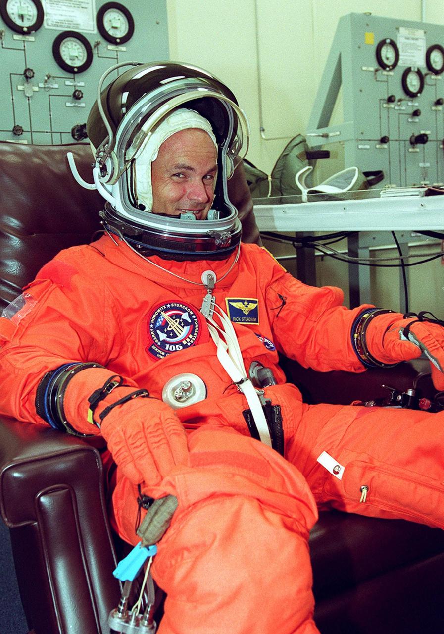
KENNEDY SPACE CENTER, Fla. -- STS-105 Pilot Rick Sturckow happy to get ready for the second launch attempt after a 24-hour weather delay. Launch countdown activities for the 12-day mission were called off at about 5:12 p.m. Aug. 9 during the T-9 minute hold due to the high potential for lightning, a thick cloud cover and the potential for showers. Launch is currently scheduled for 5:15 p.m. EDT Aug. 10. Highlighting the mission will be the rotation of the International Space Station crew, the third flight of an Italian-built Multi-Purpose Logistics Module delivering additional scientific racks, equipment and supplies for the Space Station, and two spacewalks. Included in the payload is the Early Ammonia Servicer (EAS) tank, which will be attached to the Station during the spacewalks. The EAS will be installed on the P6 truss, which holds the Station’s giant U.S. solar arrays, batteries and the cooling radiators. The EAS contains spare ammonia for the Station’s cooling system. The three-member Expedition Two crew will be returning to Earth aboard Discovery after a five-month stay on the Station
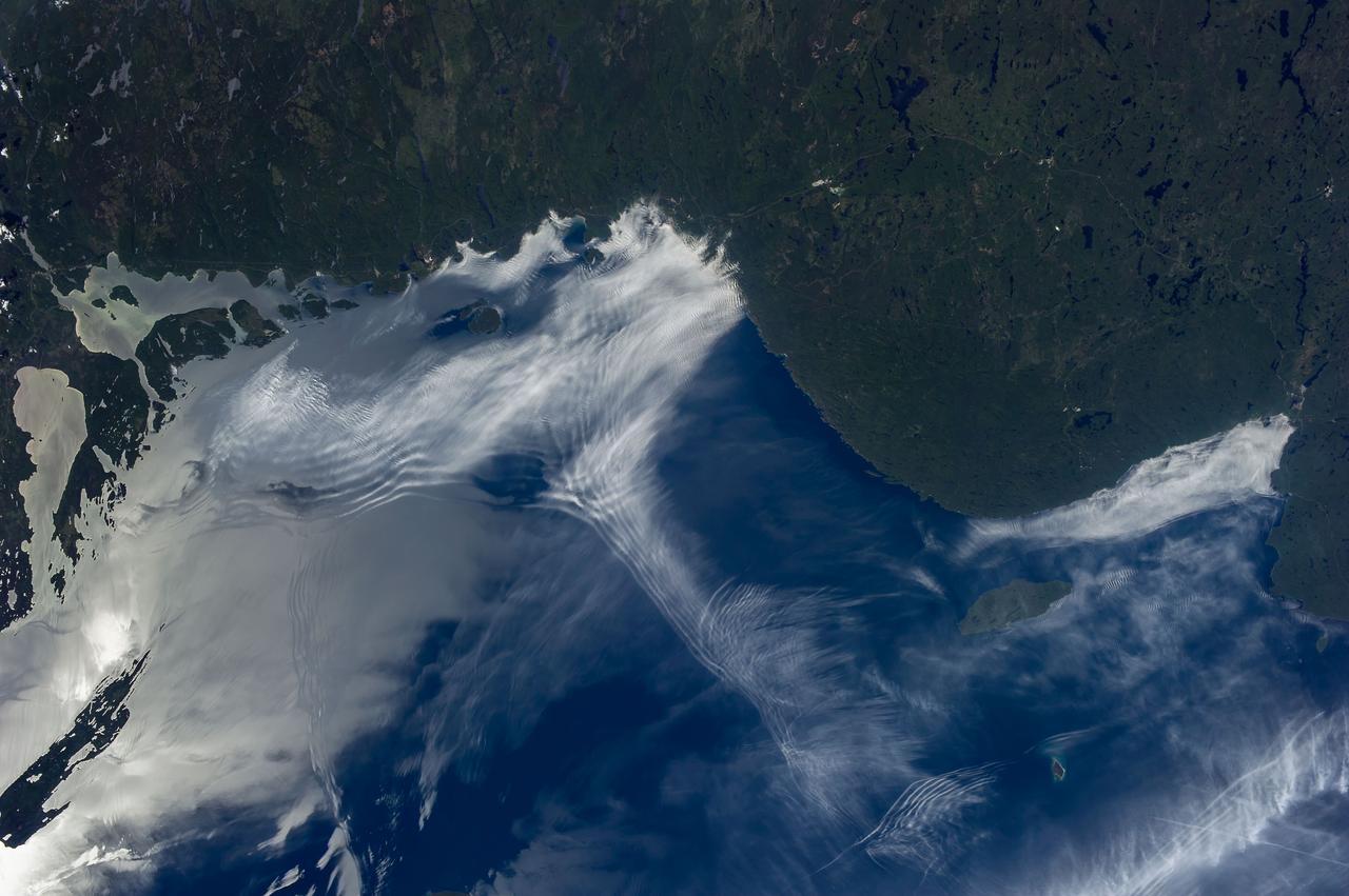
ISS036-E-011843 (24 June 2013) --- Gravity waves and sunglint on Lake Superior are featured in this image photographed by an Expedition 36 crew member on the International Space Station. From the vantage point of the space station, crew members frequently observe Earth atmospheric and surface phenomena in ways impossible to view from the ground. Two such phenomena?gravity waves and sunglint?are illustrated in this photograph of northeastern Lake Superior. The Canadian Shield of southern Ontario (bottom) is covered with extensive green forest canopy typical of early summer. Offshore, and to the west and southwest of Pukaskwa National Park several distinct sets of parallel cloud bands are visible. Gravity waves are produced when moisture-laden air encounters imbalances in air density, such as might be expected when cool air flows over warmer air; this can cause the flowing air to oscillate up and down as it moves, causing clouds to condense as the air rises (cools) and evaporate away as the air sinks (warms). This produces parallel bands of clouds oriented perpendicular to the wind direction. The orientation of the cloud bands visible in this image, parallel to the coastlines, suggests that air flowing off of the land surfaces to the north is interacting with moist, stable air over the lake surface, creating gravity waves. The second phenomenon?sunglint?effects the water surface around and to the northeast of Isle Royale (upper right). Sunglint is caused by light reflection off a water surface; some of the reflected light travels directly back towards the observer, resulting in a bright mirror-like appearance over large expanses of water. Water currents and changes in surface tension (typically caused by presence of oils or surfactants) alter the reflective properties of the water, and can be highlighted by sunglint. For example, surface water currents are visible to the east of Isle Royale that are oriented similarly to the gravity waves ? suggesting that they too are the product of winds moving off of the land surface.
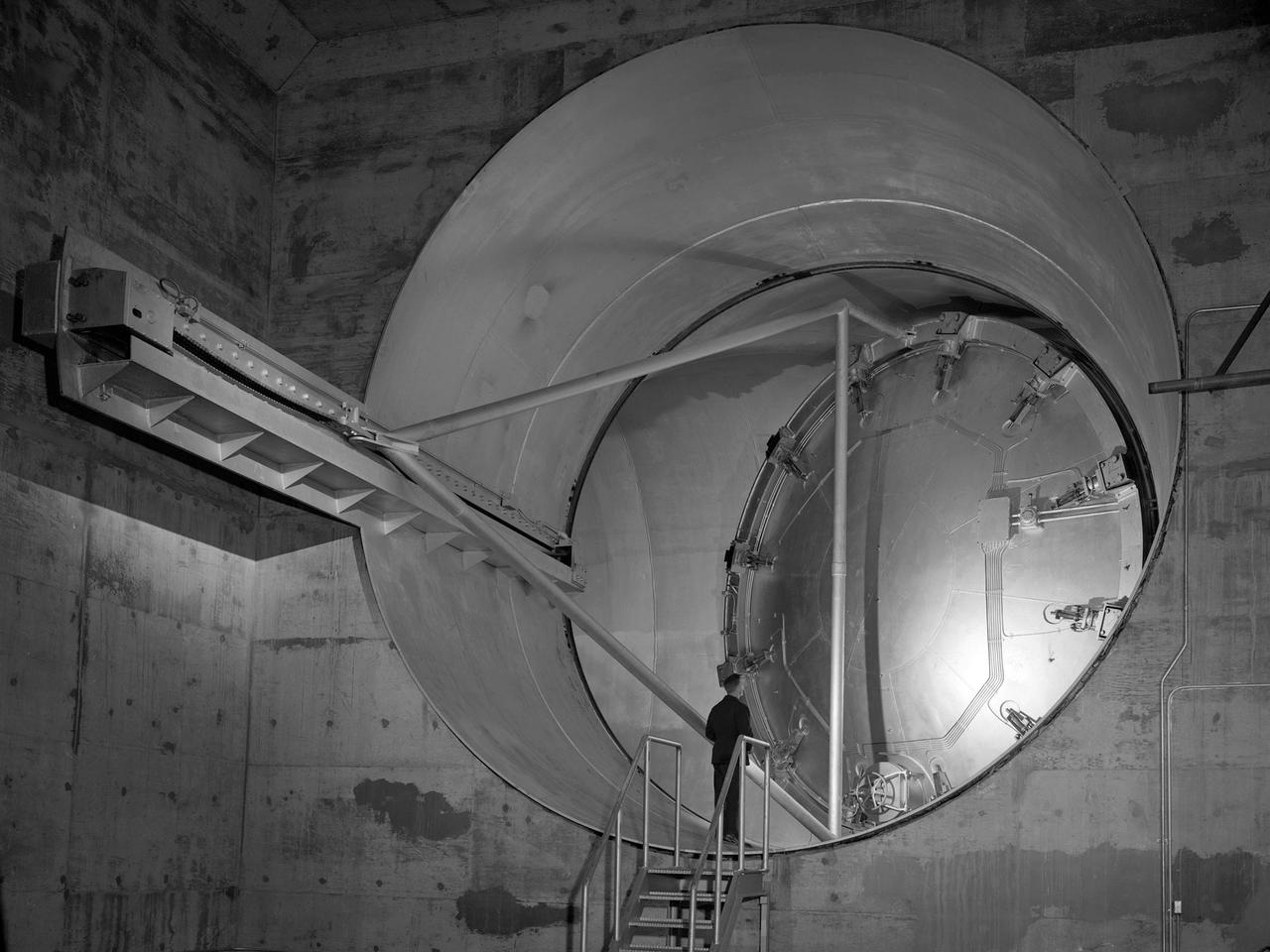
A 24-foot diameter swing valve is seen in an open position inside the new 10- by 10-Foot Supersonic Wind Tunnel at the National Advisory Committee for Aeronautics (NACA) Lewis Flight Propulsion Laboratory. The 10- by 10 was the most powerful propulsion wind tunnel in the nation. After over three years of construction the tunnel was ready to conduct its first tests in early 1956. The 10- by 10-foot tunnel was part of Congress’ Unitary Plan Act which coordinated wind tunnel construction at the NACA, Air Force, industry, and universities. The 10- by 10 was the largest of the three NACA tunnels built under the act. This large swinging valve is critical to the operation of the facility. In one position the valve seals off the tunnel exhaust, making the tunnel a closed circuit, which is used for aerodynamic testing of models. In its other position, the valve acts as a seal across the tunnel and leaves the tunnel exhaust open. This arrangement is used when engines are fired. The air going through the tunnel is taken from the atmosphere and returned to the atmosphere after one pass through the tunnel. Engines up to five feet in diameter can be tested in the 10- by 10-foot test section. Air flows up to Mach 3.5 can be fed through the test section by a 250,000-horsepower axial-flow compressor fan. The incoming air must be dehumidified and cooled so that the proper conditions are present for the test. A large air dryer with 1,890 tons of activated alumina soaks up 1.5 tons of water per minute from the air flow. A cooling apparatus equivalent to 250,000 household air conditioners is used to cool the air.
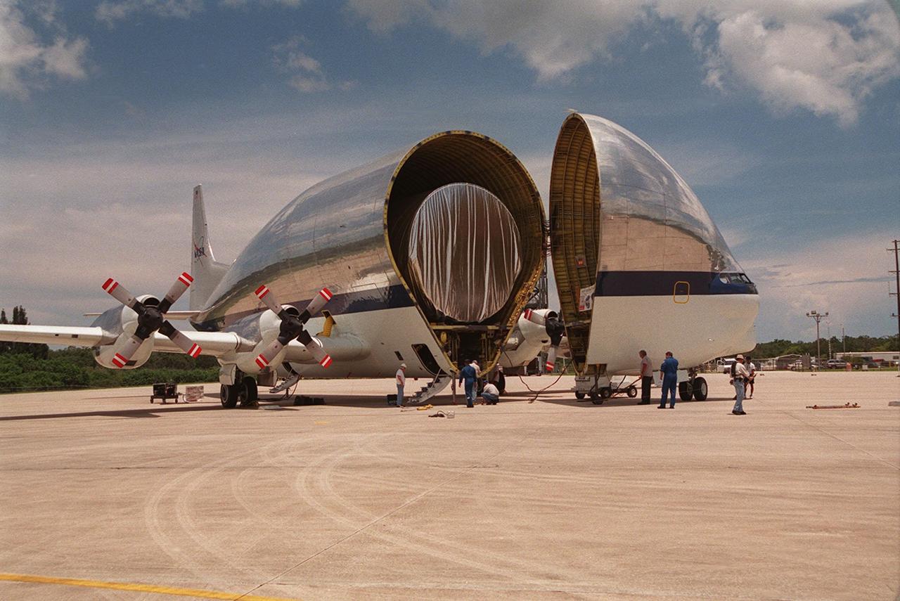
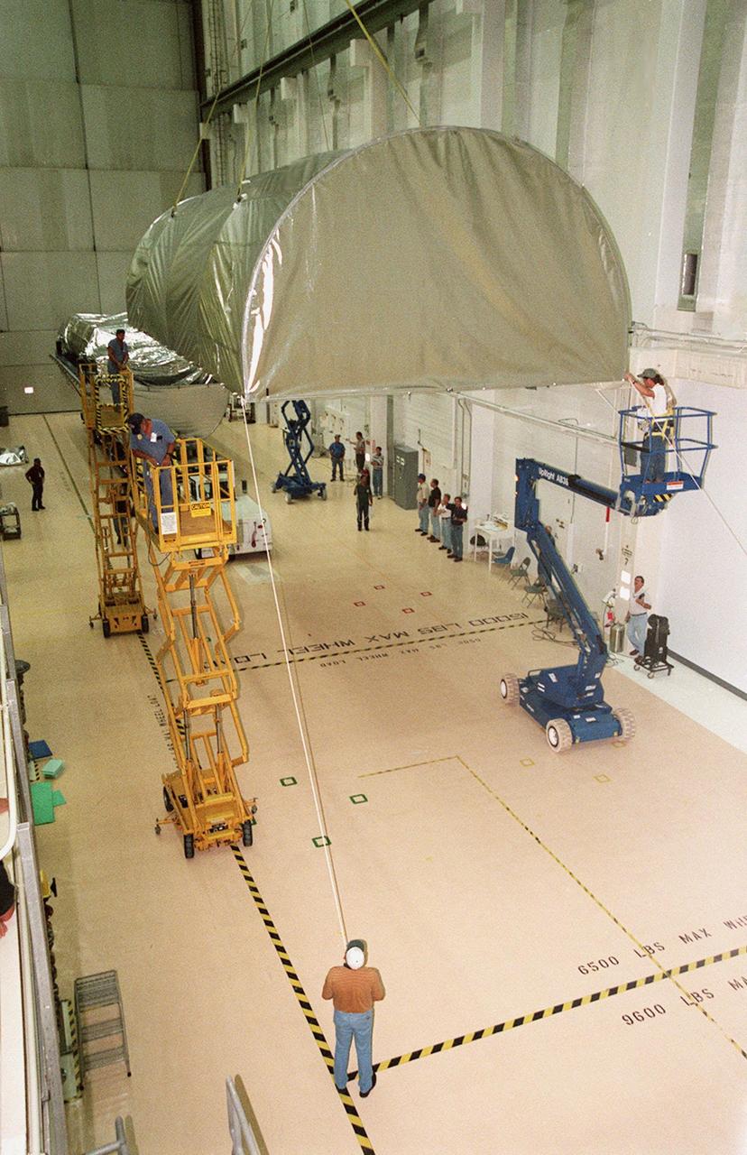
On July 26, 2000 the P-1 truss arrived at Kennedy Space Center’s Shuttle Landing Facility aboard its "Super Guppy" transport. The transport’s cargo bay was opened showing the American flag and NASA logo as the P-1 truss was off loaded in preparation for movement to the Operations and Checkout Building for processing. The P-1 truss, scheduled to fly in spring of 2002, is part of a total 10-truss, girder-like structure that will ultimately extend the length of a football field. Astronauts will attach the 14-by-15 foot structure to the port side of the center truss, SO, during the spring assembly flight. The 33,000-pound P-1 will house the thermal radiator rotating joint (TRRJ) that will rotate the International Space Station’s radiators away form the sun to increase their maximum cooling efficiency

On July 26, 2000 the P-1 truss arrived at Kennedy Space Center’s Shuttle Landing Facility aboard its "Super Guppy" transport. The transport’s cargo bay was opened showing the American flag and NASA logo as the P-1 truss was off loaded in preparation for movement to the Operations and Checkout Building for processing. The P-1 truss, scheduled to fly in spring of 2002, is part of a total 10-truss, girder-like structure that will ultimately extend the length of a football field. Astronauts will attach the 14-by-15 foot structure to the port side of the center truss, SO, during the spring assembly flight. The 33,000-pound P-1 will house the thermal radiator rotating joint (TRRJ) that will rotate the International Space Station’s radiators away from the sun to increase their maximum cooling efficiency
KENNEDY SPACE CENTER, FLA. -- Inside the Operations and Checkout Building, the top of the Guppy cargo carrier is lifted off the S1 truss (background). Manufactured by the Boeing Co. in Huntington Beach, Calif., this component of the International Space Station is the first starboard (right-side) truss segment, whose main job is providing structural support for the orbiting research facility's radiator panels that cool the Space Station's complex power system. The S1 truss segment also will house communications systems, external experiment positions and other subsystems. Primarily constructed of aluminum, the truss segment is 45 feet long, 15 feet wide and 6 feet tall. When fully outfitted, it will weigh 31,137 pounds. The truss is slated for flight in 2001
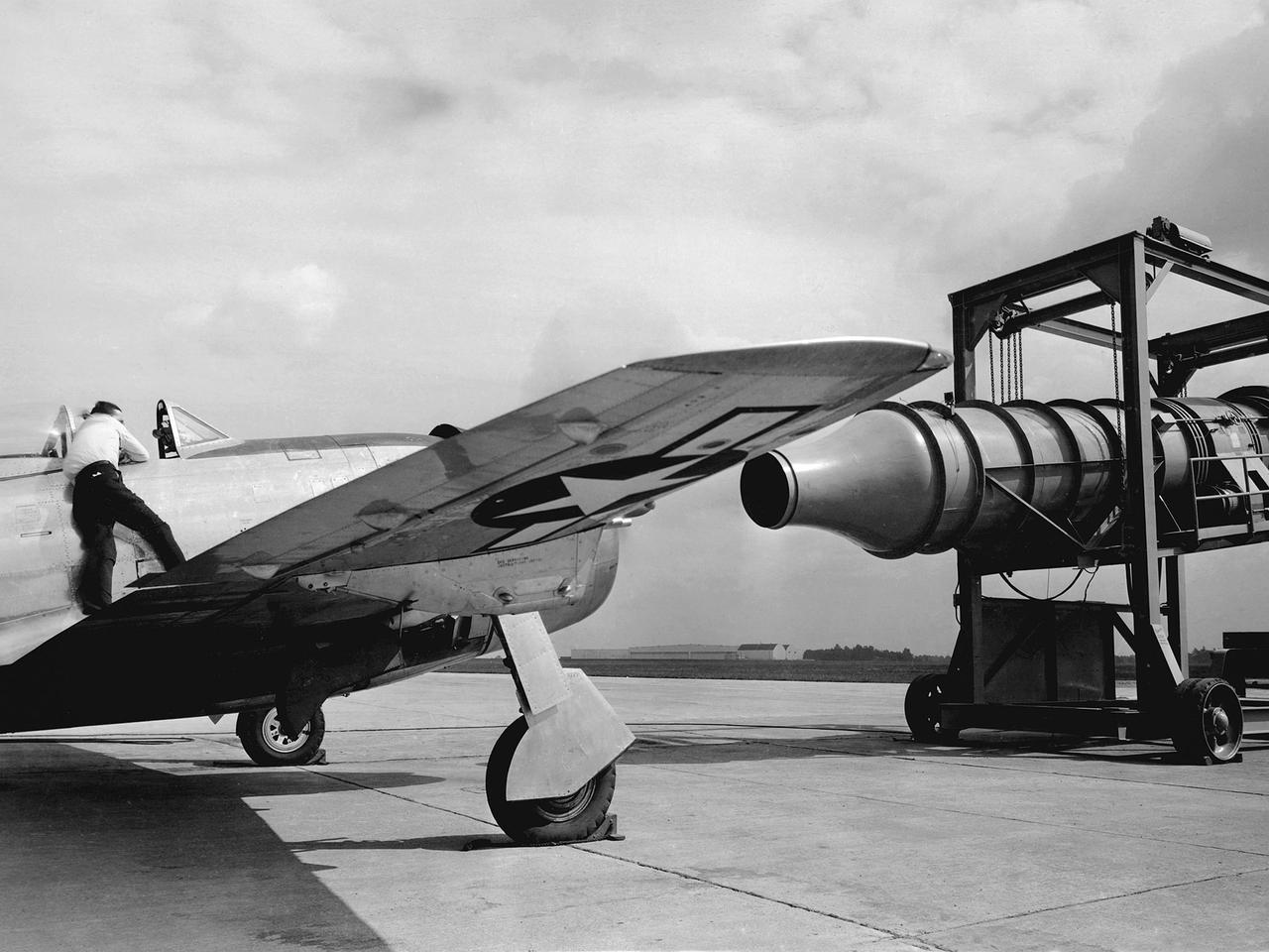
A Republic P-47G Thunderbolt is tested with a large blower on the hangar apron at the National Advisory Committee for Aeronautics (NACA) Aircraft Engine Research Laboratory in Cleveland, Ohio. The blower could produce air velocities up to 250 miles per hour. This was strong enough to simulate take-off power and eliminated the need to risk flights with untried engines. The Republic P-47G was loaned to the laboratory to test NACA modifications to the Wright R-2800 engine’s cooling system at higher altitudes. The ground-based tests, seen here, were used to map the engine’s normal operating parameters. The P-47G then underwent an extensive flight test program to study temperature distribution among the engine’s 18 cylinders and develop methods to improve that distribution.
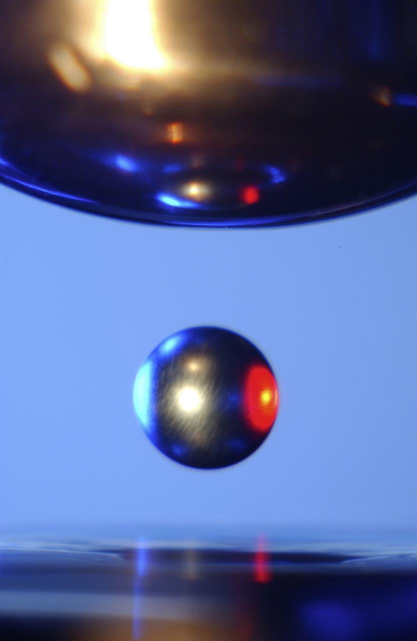
This Photo, which appeared on the July cover of `Physics Today', is of the Electrostatic Levitator (ESL) at NASA's Marshall Space Flight Center (MSFC). The ESL uses static electricity to suspend an object (about 3-4 mm in diameter) inside a vacuum chamber allowing scientists to record a wide range of physical properties without the sample contracting the container or any instruments, conditions that would alter the readings. Once inside the chamber, a laser heats the sample until it melts. The laser is then turned off and the sample cools, changing from a liquid drop to a solid sphere. In this particular shot, the ESL contains a solid metal sample of titanium-zirconium-nickel alloy. Since 1977, the ESL has been used at MSFC to study the characteristics of new metals, ceramics, and glass compounds. Materials created as a result of these tests include new optical materials, special metallic glasses, and spacecraft components.

On July 26, 2000 the P-1 truss arrived at Kennedy Space Center’s Shuttle Landing Facility aboard its "Super Guppy" transport. The transport’s cargo bay was opened showing the American flag and NASA logo as the P-1 truss was off loaded in preparation for movement to the Operations and Checkout Building for processing. The P-1 truss, scheduled to fly in spring of 2002, is part of a total 10-truss, girder-like structure that will ultimately extend the length of a football field. Astronauts will attach the 14-by-15 foot structure to the port side of the center truss, SO, during the spring assembly flight. The 33,000-pound P-1 will house the thermal radiator rotating joint (TRRJ) that will rotate the International Space Station’s radiators away form the sun to increase their maximum cooling efficiency
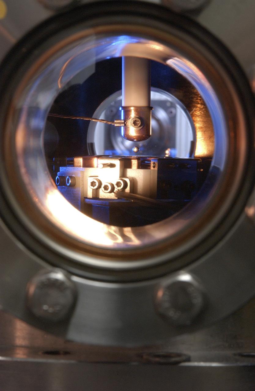
This is a close-up of a sample of titanium-zirconium-nickel alloy inside the Electrostatic Levitator (ESL) vacuum chamber at NASA's Marshall Space Flight Center (MSFC). The ESL uses static electricity to suspend an object (about 3-4 mm in diameter) inside a vacuum chamber allowing scientists to record a wide range of physical properties without the sample contracting the container or any instruments, conditions that would alter the readings. Once inside the chamber, a laser heats the sample until it melts. The laser is then turned off and the sample cools, changing from a liquid drop to a solid sphere. Since 1977, the ESL has been used at MSFC to study the characteristics of new metals, ceramics, and glass compounds. Materials created as a result of these tests include new optical materials, special metallic glasses, and spacecraft components.
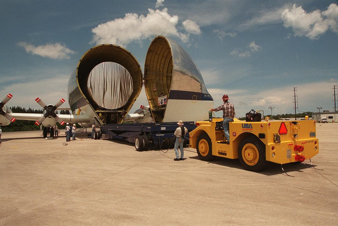
On July 26, 2000 the P-1 truss arrived at Kennedy Space Center’s Shuttle Landing Facility aboard its "Super Guppy" transport. A flatbed truck was backed up to begin the off loading of the P-1 truss in preparation for movement to the Operations and Checkout Building for processing. The P-1 truss, scheduled to fly in spring of 2002, is part of a total 10-truss, girder-like structure that will ultimately extend the length of a football field. Astronauts will attach the 14-by-15 foot structure to the port side of the center truss, SO, during the spring assembly flight. The 33,000-pound P-1 will house the thermal radiator rotating joint (TRRJ) that will rotate the International Space Station’s radiators away from the sun to increase their maximum cooling efficiency
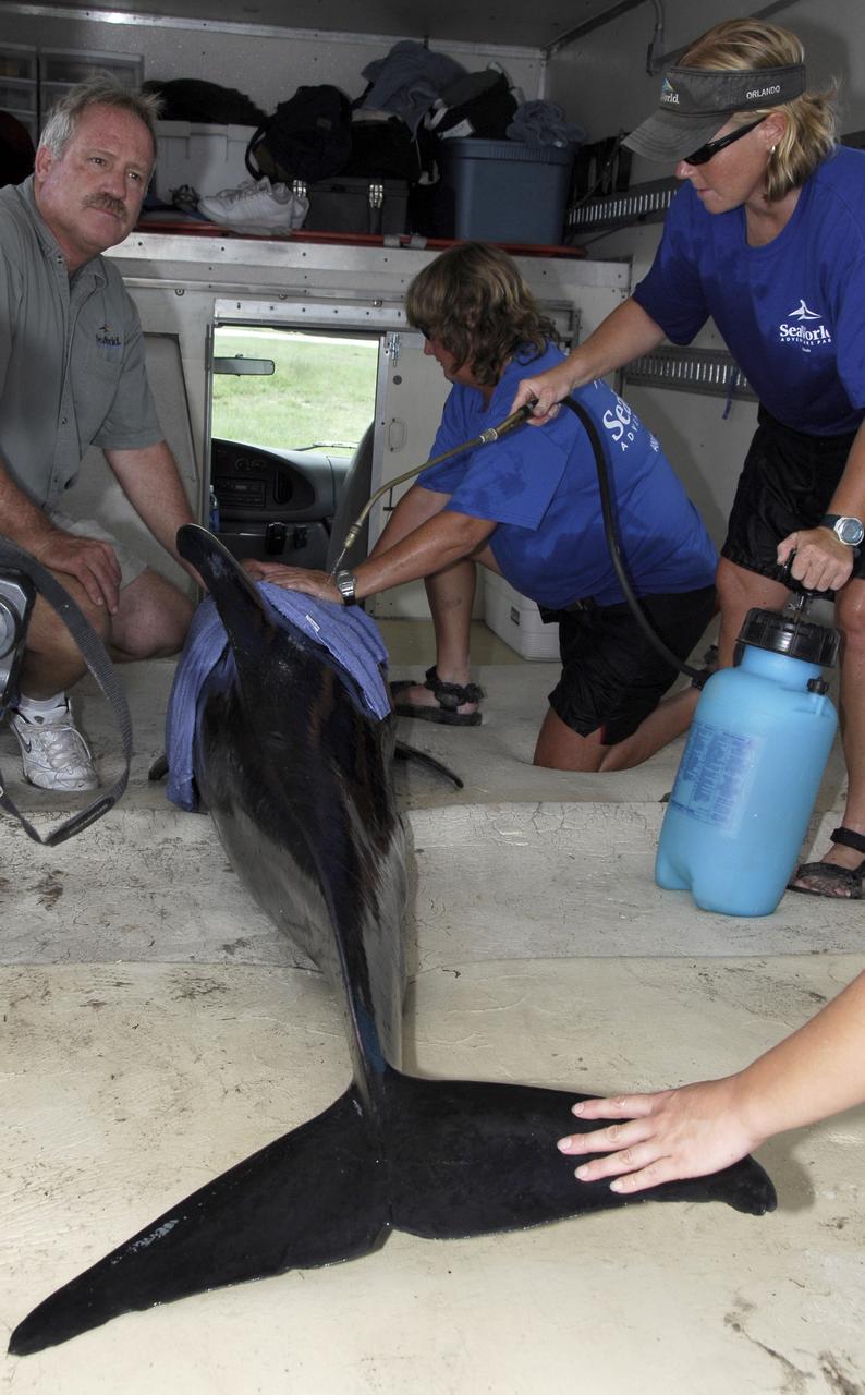
CAPE CANAVERAL, Fla. – Inside a truck, a veterinarian, left, and Sea World representatives cool the skin of a Melon-Headed Whale found stranded south of Launch Pad 39A at NASA's Kennedy Space Center near Cape Canaveral Air Force Station. The whale will be taken to Sea World for evaluation. After assessment by veterinarians at Sea World, the whale will be transported to a whale rescue center in the Panhandle for rehabilitation and release. The Melon-Headed Whale lives well off-shore in all the world's tropical and sub-tropical oceans. At the northern fringes of its range, it may also be found in the warm currents of temperate waters, such as Florida. It is closely related to the Pygmy Killer Whale and the Pilot Whales. Its primary diet is squid. Photo credit: NASA/Kim Shiflett
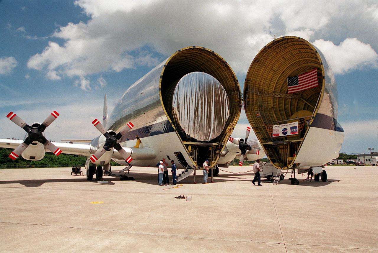
On July 26, 2000 the P-1 truss arrived at Kennedy Space Center’s Shuttle Landing Facility aboard its "Super Guppy" transport. The transport’s cargo bay was opened showing the American flag and NASA logo as the P-1 truss was off loaded in preparation for movement to the Operations and Checkout Building for processing. The P-1 truss, scheduled to fly in spring of 2002, is part of a total 10-truss, girder-like structure that will ultimately extend the length of a football field. Astronauts will attach the 14-by-15 foot structure to the port side of the center truss, SO, during the spring assembly flight. The 33,000-pound P-1 will house the thermal radiator rotating joint (TRRJ) that will rotate the International Space Station’s radiators away from the sun to increase their maximum cooling efficiency

On July 26, 2000 the P-1 truss arrived at Kennedy Space Center’s Shuttle Landing Facility aboard its "Super Guppy" transport. A flatbed truck was backed up to begin the off loading of the P-1 truss in preparation for movement to the Operations and Checkout Building for processing. The P-1 truss, scheduled to fly in spring of 2002, is part of a total 10-truss, girder-like structure that will ultimately extend the length of a football field. Astronauts will attach the 14-by-15 foot structure to the port side of the center truss, SO, during the spring assembly flight. The 33,000-pound P-1 will house the thermal radiator rotating joint (TRRJ) that will rotate the International Space Station’s radiators away from the sun to increase their maximum cooling efficiency
![On June 26, 2016, the Moderate Resolution Imaging Spectroradiometer (MODIS) on NASA’s Terra satellite acquired this natural-color image of cloud gravity waves off the coast of Angola and Namibia. “I [regularly] look at this area on Worldview because you quite often have these gravity waves,” said Bastiaan Van Diedenhoven, a researcher for Columbia University and NASA's Goddard Institute for Space Studies interested in cloud formations. “On this day, there was so much going on—so many different waves from different directions—that they really started interfering.” A distinctive criss-cross pattern formed in unbroken stretches hundreds of kilometers long. Similar to a boat’s wake, which forms as the water is pushed upward by the boat and pulled downward again by gravity, these clouds are formed by the rise and fall of colliding air columns. Off of west Africa, dry air coming off the Namib desert—after being cooled by the night—moves out under the balmy, moist air over the ocean and bumps it upwards. As the humid air rises to a higher altitude, the moisture condenses into droplets, forming clouds. Gravity rolls these newly formed clouds into a wave-like shape. When moist air goes up, it cools, and then gravity pushes it down again. As it plummets toward the earth, the moist air is pushed up again by the dry air. Repeated again and again, this process creates gravity waves. Clouds occur at the upward wave motions, while they evaporate at the downward motions. Such waves will often propagate in the morning and early afternoon, said Van Diedenhoven. During the course of the day, the clouds move out to sea and stretch out, as the dry air flowing off the land pushes the moist ocean air westward. NASA Earth Observatory image by Jesse Allen, using data from the Land Atmosphere Near real-time Capability for EOS (LANCE). via @NASAEarth <a href="http://go.nasa.gov/29Btxcy" rel="nofollow">go.nasa.gov/29Btxcy</a> <b><a href="http://go.nasa.gov/29BtHR6" rel="nofollow">NASA image use policy.</a></b> <b><a href="http://go.nasa.gov/29BtDku" rel="nofollow">NASA Goddard Space Flight Center</a></b> enables NASA’s mission through four scientific endeavors: Earth Science, Heliophysics, Solar System Exploration, and Astrophysics. Goddard plays a leading role in NASA’s accomplishments by contributing compelling scientific knowledge to advance the Agency’s mission. <b>Follow us on <a href="http://go.nasa.gov/29BtVrn" rel="nofollow">Twitter</a></b> <b>Like us on <a href="http://go.nasa.gov/29BtygK" rel="nofollow">Facebook</a></b> <b>Find us on <a href="http://go.nasa.gov/29Bu0vu" rel="nofollow">Instagram</a></b>](https://images-assets.nasa.gov/image/GSFC_20171208_Archive_e000269/GSFC_20171208_Archive_e000269~medium.jpg)
On June 26, 2016, the Moderate Resolution Imaging Spectroradiometer (MODIS) on NASA’s Terra satellite acquired this natural-color image of cloud gravity waves off the coast of Angola and Namibia. “I [regularly] look at this area on Worldview because you quite often have these gravity waves,” said Bastiaan Van Diedenhoven, a researcher for Columbia University and NASA's Goddard Institute for Space Studies interested in cloud formations. “On this day, there was so much going on—so many different waves from different directions—that they really started interfering.” A distinctive criss-cross pattern formed in unbroken stretches hundreds of kilometers long. Similar to a boat’s wake, which forms as the water is pushed upward by the boat and pulled downward again by gravity, these clouds are formed by the rise and fall of colliding air columns. Off of west Africa, dry air coming off the Namib desert—after being cooled by the night—moves out under the balmy, moist air over the ocean and bumps it upwards. As the humid air rises to a higher altitude, the moisture condenses into droplets, forming clouds. Gravity rolls these newly formed clouds into a wave-like shape. When moist air goes up, it cools, and then gravity pushes it down again. As it plummets toward the earth, the moist air is pushed up again by the dry air. Repeated again and again, this process creates gravity waves. Clouds occur at the upward wave motions, while they evaporate at the downward motions. Such waves will often propagate in the morning and early afternoon, said Van Diedenhoven. During the course of the day, the clouds move out to sea and stretch out, as the dry air flowing off the land pushes the moist ocean air westward. NASA Earth Observatory image by Jesse Allen, using data from the Land Atmosphere Near real-time Capability for EOS (LANCE). via @NASAEarth <a href="http://go.nasa.gov/29Btxcy" rel="nofollow">go.nasa.gov/29Btxcy</a> <b><a href="http://go.nasa.gov/29BtHR6" rel="nofollow">NASA image use policy.</a></b> <b><a href="http://go.nasa.gov/29BtDku" rel="nofollow">NASA Goddard Space Flight Center</a></b> enables NASA’s mission through four scientific endeavors: Earth Science, Heliophysics, Solar System Exploration, and Astrophysics. Goddard plays a leading role in NASA’s accomplishments by contributing compelling scientific knowledge to advance the Agency’s mission. <b>Follow us on <a href="http://go.nasa.gov/29BtVrn" rel="nofollow">Twitter</a></b> <b>Like us on <a href="http://go.nasa.gov/29BtygK" rel="nofollow">Facebook</a></b> <b>Find us on <a href="http://go.nasa.gov/29Bu0vu" rel="nofollow">Instagram</a></b>
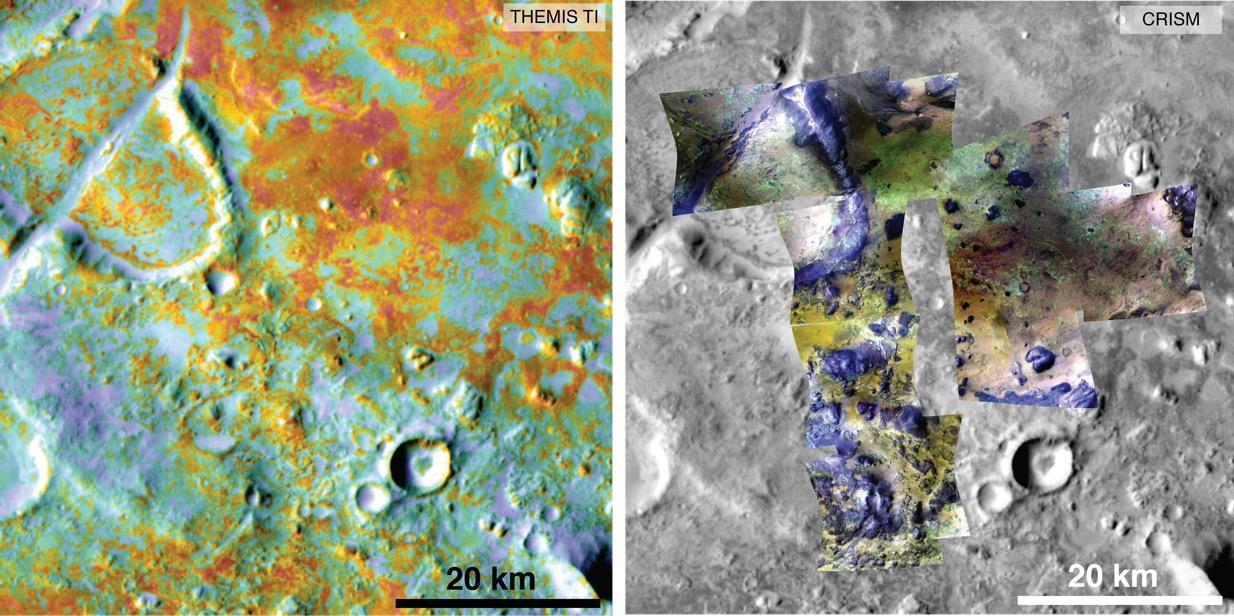
Researchers estimating the amount of carbon held in the ground at the largest known carbonate-containing deposit on Mars utilized data from three different NASA Mars orbiters. Each image in this pair covers the same area about 36 miles (58 kilometers) wide in the Nili Fossae plains region of Mars' northern hemisphere. The tally of carbon content in the rocks of this region is a key piece in solving a puzzle of how the Martian atmosphere has changed over time. Carbon dioxide from the atmosphere on early Mars reacted with surface rocks to form carbonate, thinning the atmosphere. The image on the left presents data from the Thermal Emission Imaging System (THEMIS) instrument on NASA's Mars Odyssey orbiter. The color coding indicates thermal inertia -- the property of how quickly a surface material heats up or cools off. Sand, for example (blue hues), cools off quicker after sundown than bedrock (red hues) does. The color coding in the image on the right presents data from the Compact Reconnaissance Imaging Spectrometer for Mars (CRISM) instrument on NASA's Mars Reconnaissance Orbiter. From the brightness at many different wavelengths, CRISM data can indicate what minerals are present on the surface. In the color coding used here, green hues are consistent with carbonate-bearing materials, while brown or yellow hues are olivine-bearing sands and locations with purple hues are basaltic in composition. The gray scale base map is a mosaic of daytime THEMIS infrared images. Annotations point to areas with different surface compositions. The scale bar indicates 20 kilometers (12.4 miles). http://photojournal.jpl.nasa.gov/catalog/PIA19816
This image shows teams at NASA’s Michoud Assembly Facility lifting a completed dome off of a robotic weld tool on Nov. 21. The dome, which will cap off the aft end of the liquid hydrogen tank, will be used on the core stage of the SLS (Space Launch System) rocket for the agency’s Artemis IV mission. Later, technicians from Boeing – NASA’s prime contractor for SLS – will join the aft dome with five barrels and a forward dome to complete the liquid hydrogen tank. Artemis IV is the first flight of SLS in its Block 1B configuration. The SLS core stage liquid hydrogen tank holds 537,000 gallons of super-cooled propellant and is one of five unique elements that make up the SLS core stage. Together with the forward skirt, liquid oxygen tank, intertank, and engine section, the liquid hydrogen tank will provide propellant to the four RS-25 engines to produce more than two million pounds of thrust to help launch NASA’s Orion spacecraft, astronauts, and supplies beyond Earth’s orbit to the Moon. Image credit: NASA/Michael DeMocker
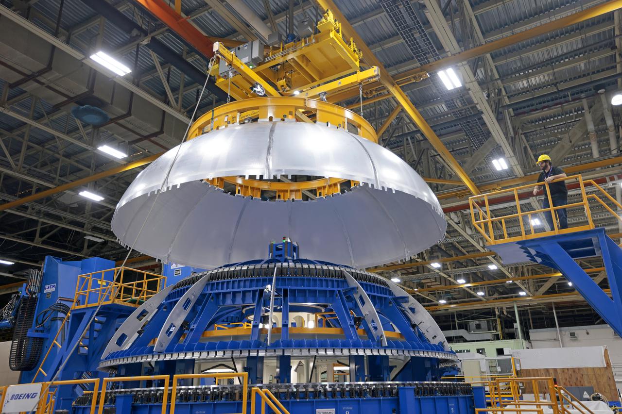
This image shows teams at NASA’s Michoud Assembly Facility lifting a completed dome off of a robotic weld tool on Nov. 21. The dome, which will cap off the aft end of the liquid hydrogen tank, will be used on the core stage of the SLS (Space Launch System) rocket for the agency’s Artemis IV mission. Later, technicians from Boeing – NASA’s prime contractor for SLS – will join the aft dome with five barrels and a forward dome to complete the liquid hydrogen tank. Artemis IV is the first flight of SLS in its Block 1B configuration. The SLS core stage liquid hydrogen tank holds 537,000 gallons of super-cooled propellant and is one of five unique elements that make up the SLS core stage. Together with the forward skirt, liquid oxygen tank, intertank, and engine section, the liquid hydrogen tank will provide propellant to the four RS-25 engines to produce more than two million pounds of thrust to help launch NASA’s Orion spacecraft, astronauts, and supplies beyond Earth’s orbit to the Moon. Image credit: NASA/Michael DeMocker

This image shows NASA’s Michoud Assembly Facility move crew lifting a completed liquid hydrogen tank barrel off the Vertical Weld Center on Feb. 10. The barrel, which will be used on the core stage of NASA’s SLS (Space Launch System) rocket, is one of the first pieces of flight hardware manufactured for the agency’s Artemis V mission. The 22-foot-tall barrel section is one of five barrels, which – along with two end domes – make up the 130.8-foot-tall liquid hydrogen fuel tank. The SLS core stage liquid hydrogen tank holds 537,000 gallons of super-cooled propellant and is one of five unique elements that make up the SLS core stage. Together with the forward skirt, liquid oxygen tank, intertank, and engine section, the liquid hydrogen tank will provide propellant to the four RS-25 engines to produce more than two million pounds of thrust to help launch NASA’s Orion spacecraft, astronauts, and supplies beyond Earth’s orbit to the Moon.

This image shows NASA’s Michoud Assembly Facility move crew lifting a completed liquid hydrogen tank barrel off the Vertical Weld Center on Feb. 10. The barrel, which will be used on the core stage of NASA’s SLS (Space Launch System) rocket, is one of the first pieces of flight hardware manufactured for the agency’s Artemis V mission. The 22-foot-tall barrel section is one of five barrels, which – along with two end domes – make up the 130.8-foot-tall liquid hydrogen fuel tank. The SLS core stage liquid hydrogen tank holds 537,000 gallons of super-cooled propellant and is one of five unique elements that make up the SLS core stage. Together with the forward skirt, liquid oxygen tank, intertank, and engine section, the liquid hydrogen tank will provide propellant to the four RS-25 engines to produce more than two million pounds of thrust to help launch NASA’s Orion spacecraft, astronauts, and supplies beyond Earth’s orbit to the Moon.

This image shows NASA’s Michoud Assembly Facility move crew lifting a completed liquid hydrogen tank barrel off the Vertical Weld Center on Feb. 10. The barrel, which will be used on the core stage of NASA’s SLS (Space Launch System) rocket, is one of the first pieces of flight hardware manufactured for the agency’s Artemis V mission. The 22-foot-tall barrel section is one of five barrels, which – along with two end domes – make up the 130.8-foot-tall liquid hydrogen fuel tank. The SLS core stage liquid hydrogen tank holds 537,000 gallons of super-cooled propellant and is one of five unique elements that make up the SLS core stage. Together with the forward skirt, liquid oxygen tank, intertank, and engine section, the liquid hydrogen tank will provide propellant to the four RS-25 engines to produce more than two million pounds of thrust to help launch NASA’s Orion spacecraft, astronauts, and supplies beyond Earth’s orbit to the Moon

This image shows NASA’s Michoud Assembly Facility move crew lifting a completed liquid hydrogen tank barrel off the Vertical Weld Center on Feb. 10. The barrel, which will be used on the core stage of NASA’s SLS (Space Launch System) rocket, is one of the first pieces of flight hardware manufactured for the agency’s Artemis V mission. The 22-foot-tall barrel section is one of five barrels, which – along with two end domes – make up the 130.8-foot-tall liquid hydrogen fuel tank. The SLS core stage liquid hydrogen tank holds 537,000 gallons of super-cooled propellant and is one of five unique elements that make up the SLS core stage. Together with the forward skirt, liquid oxygen tank, intertank, and engine section, the liquid hydrogen tank will provide propellant to the four RS-25 engines to produce more than two million pounds of thrust to help launch NASA’s Orion spacecraft, astronauts, and supplies beyond Earth’s orbit to the Moon.

This image shows NASA’s Michoud Assembly Facility move crew lifting a completed liquid hydrogen tank barrel off the Vertical Weld Center on Feb. 10. The barrel, which will be used on the core stage of NASA’s SLS (Space Launch System) rocket, is one of the first pieces of flight hardware manufactured for the agency’s Artemis V mission. The 22-foot-tall barrel section is one of five barrels, which – along with two end domes – make up the 130.8-foot-tall liquid hydrogen fuel tank. The SLS core stage liquid hydrogen tank holds 537,000 gallons of super-cooled propellant and is one of five unique elements that make up the SLS core stage. Together with the forward skirt, liquid oxygen tank, intertank, and engine section, the liquid hydrogen tank will provide propellant to the four RS-25 engines to produce more than two million pounds of thrust to help launch NASA’s Orion spacecraft, astronauts, and supplies beyond Earth’s orbit to the Moon.

This image shows NASA’s Michoud Assembly Facility move crew lifting a completed liquid hydrogen tank barrel off the Vertical Weld Center on Feb. 10. The barrel, which will be used on the core stage of NASA’s SLS (Space Launch System) rocket, is one of the first pieces of flight hardware manufactured for the agency’s Artemis V mission. The 22-foot-tall barrel section is one of five barrels, which – along with two end domes – make up the 130.8-foot-tall liquid hydrogen fuel tank. The SLS core stage liquid hydrogen tank holds 537,000 gallons of super-cooled propellant and is one of five unique elements that make up the SLS core stage. Together with the forward skirt, liquid oxygen tank, intertank, and engine section, the liquid hydrogen tank will provide propellant to the four RS-25 engines to produce more than two million pounds of thrust to help launch NASA’s Orion spacecraft, astronauts, and supplies beyond Earth’s orbit to the Moon.

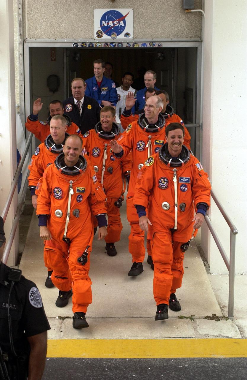
KENNEDY SPACE CENTER, Fla. -- The STS-105 and Expedition Three (E3) crews are smiling as they exit the Operations and Checkout Building on their way to Launch Pad 39A for a second launch attempt. Leading the way are (left to right) Pilot Rick Sturckow and Commander Scott Horowitz; in the second row, Mission Specialists Patrick Forrester and Daniel Barry; in the third row, E3 cosmonaut Mikhail Tyurin, Commander Frank Culbertson, and cosmonaut Vladimir Dezhurov. Forrester and Tyurin are both making their first space flights. Launch countdown activities for the 12-day mission were called off at about 5:12 p.m. Aug. 9 during the T-9 minute hold due to the high potential for lightning, a thick cloud cover and the potential for showers. Highlighting the mission will be the rotation of the International Space Station crew, the third flight of an Italian-built Multi-Purpose Logistics Module delivering additional scientific racks, equipment and supplies for the Space Station, and two spacewalks. Included in the payload is the Early Ammonia Servicer (EAS) tank, which will be attached to the Station during the spacewalks. The EAS will be installed on the P6 truss, which holds the Station’s giant U.S. solar arrays, batteries and the cooling radiators. The EAS contains spare ammonia for the Station’s cooling system. The three-member Expedition Two crew will be returning to Earth aboard Discovery after a five-month stay on the Station. Launch is scheduled for 5:15 p.m. EDT Aug. 10. [Photo by Scott Andrews; Nikon D1X camera
KENNEDY SPACE CENTER, Fla. -- The STS-105 and Expedition Three (E3) crews are smiling as they exit the Operations and Checkout Building on their way to Launch Pad 39A for a second launch attempt. Leading the way are (left to right) Pilot Rick Sturckow and Commander Scott Horowitz; in the second row, Mission Specialists Patrick Forrester and Daniel Barry; in the third row, E3 cosmonaut Mikhail Tyurin, Commander Frank Culbertson, and cosmonaut Vladimir Dezhurov. Forrester and Tyurin are both making their first space flights. Launch countdown activities for the 12-day mission were called off at about 5:12 p.m. Aug. 9 during the T-9 minute hold due to the high potential for lightning, a thick cloud cover and the potential for showers. Highlighting the mission will be the rotation of the International Space Station crew, the third flight of an Italian-built Multi-Purpose Logistics Module delivering additional scientific racks, equipment and supplies for the Space Station, and two spacewalks. Included in the payload is the Early Ammonia Servicer (EAS) tank, which will be attached to the Station during the spacewalks. The EAS will be installed on the P6 truss, which holds the Station’s giant U.S. solar arrays, batteries and the cooling radiators. The EAS contains spare ammonia for the Station’s cooling system. The three-member Expedition Two crew will be returning to Earth aboard Discovery after a five-month stay on the Station. Launch is scheduled for 5:15 p.m. EDT Aug. 10. [Photo by Scott Andrews; Nikon D1X camera
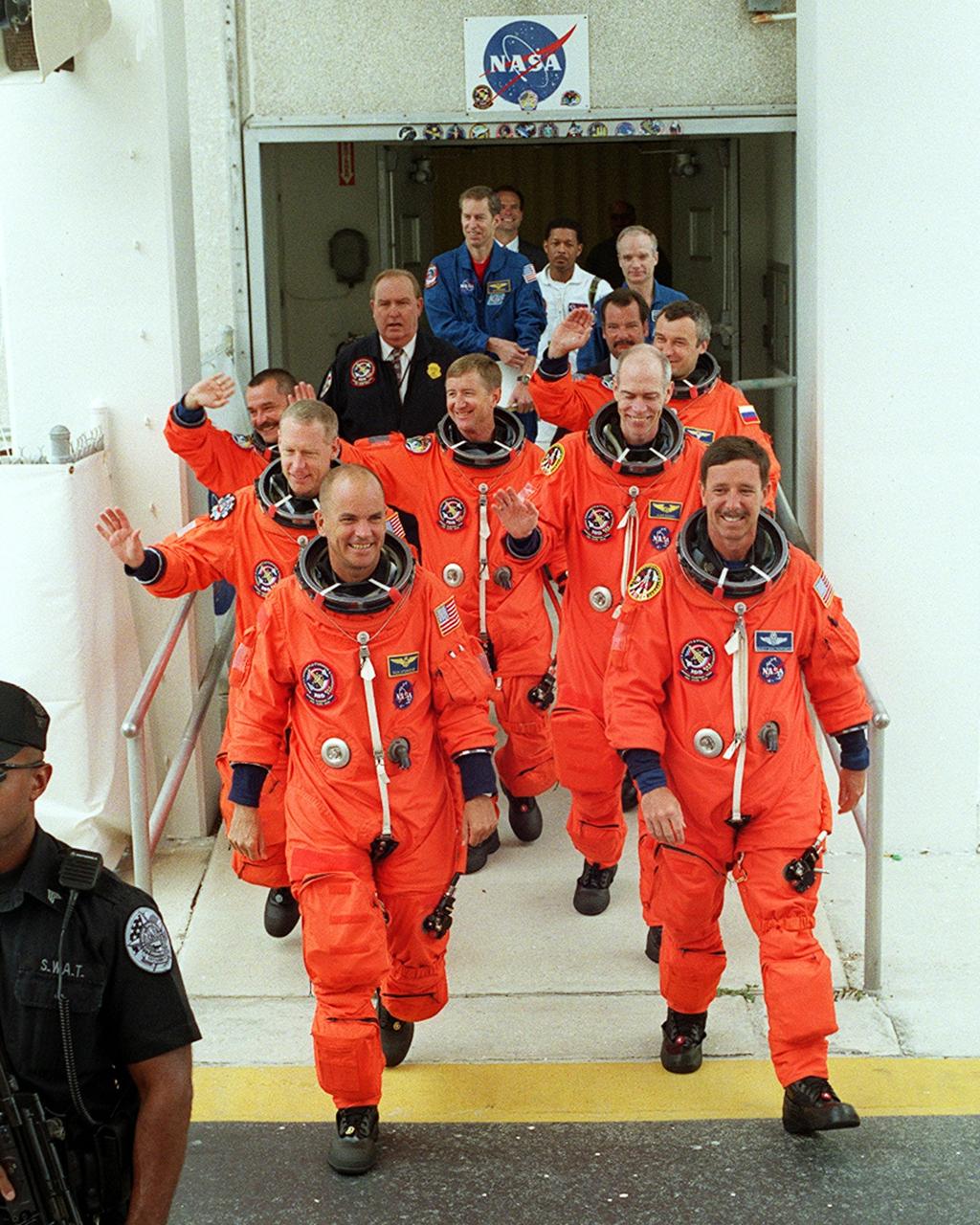
KENNEDY SPACE CENTER, Fla. -- The STS-105 and Expedition Three (E3) crews grin as they exit the Operations and Checkout Building on their way to Launch Pad 39A for a second launch attempt. Leading the way are (left to right) Pilot Rick Sturckow and Commander Scott Horowitz; in the second row, Mission Specialists Patrick Forrester and Daniel Barry; in the third row, E3 cosmonaut Mikhail Tyurin, Commander Frank Culbertson, and cosmonaut Vladimir Dezhurov. Forrester and Tyurin are both making their first space flights. Launch countdown activities for the 12-day mission were called off at about 5:12 p.m. Aug. 9 during the T-9 minute hold due to the high potential for lightning, a thick cloud cover and the potential for showers. Launch is currently scheduled for 5:15 p.m. EDT Aug. 10. Highlighting the mission will be the rotation of the International Space Station crew, the third flight of an Italian-built Multi-Purpose Logistics Module delivering additional scientific racks, equipment and supplies for the Space Station, and two spacewalks. Included in the payload is the Early Ammonia Servicer (EAS) tank, which will be attached to the Station during the spacewalks. The EAS will be installed on the P6 truss, which holds the Station’s giant U.S. solar arrays, batteries and the cooling radiators. The EAS contains spare ammonia for the Station’s cooling system. The three-member Expedition Two crew will be returning to Earth aboard Discovery after a five-month stay on the Station
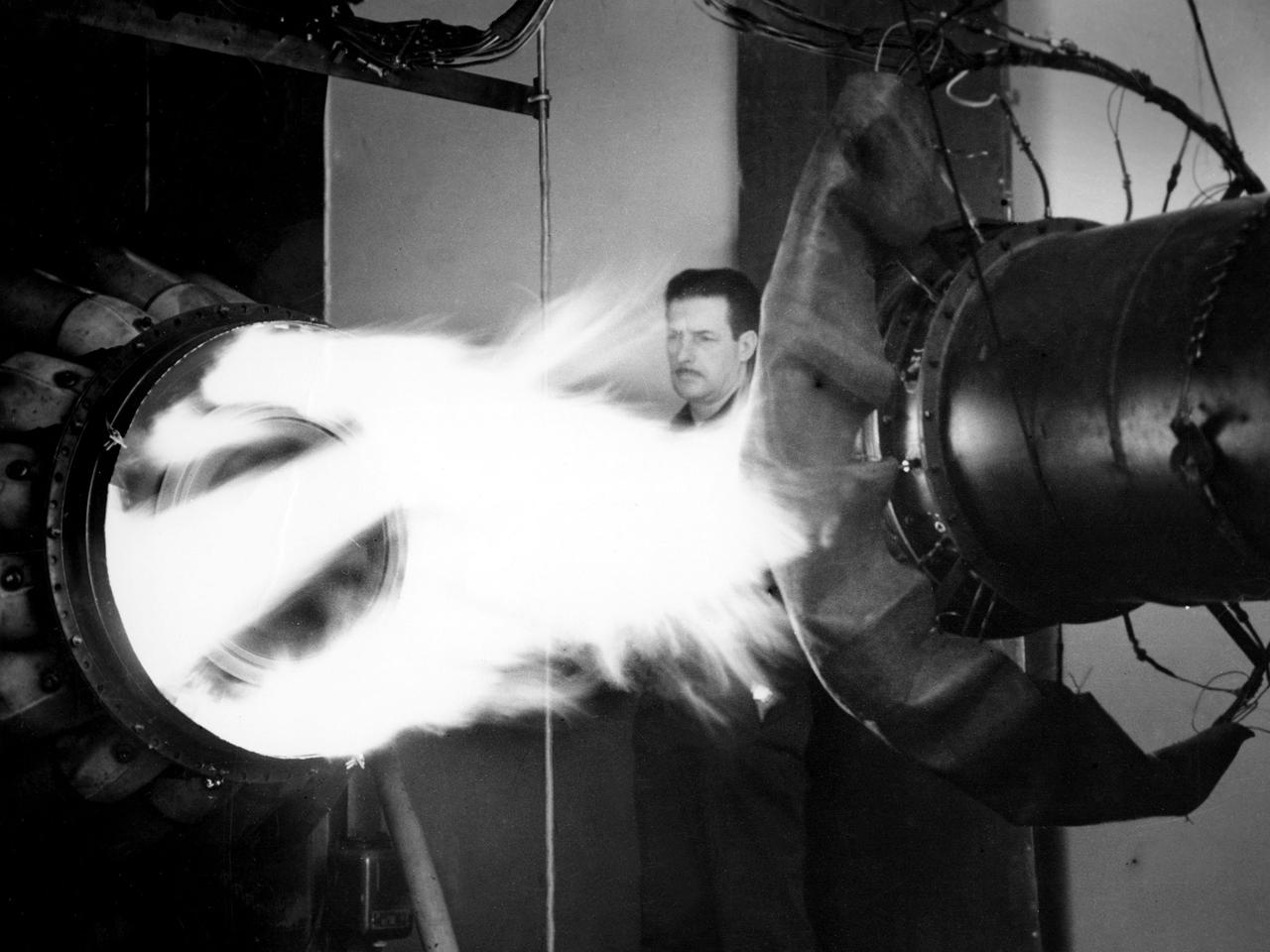
A mechanic watches the firing of a General Electric I-40 turbojet at the National Advisory Committee for Aeronautics (NACA) Lewis Flight Propulsion Laboratory. The military selected General Electric’s West Lynn facility in 1941 to secretly replicate the centrifugal turbojet engine designed by British engineer Frank Whittle. General Electric’s first attempt, the I-A, was fraught with problems. The design was improved somewhat with the subsequent I-16 engine. It was not until the engine's next reincarnation as the I-40 in 1943 that General Electric’s efforts paid off. The 4000-pound thrust I-40 was incorporated into the Lockheed Shooting Star airframe and successfully flown in June 1944. The Shooting Star became the US’s first successful jet aircraft and the first US aircraft to reach 500 miles per hour. NACA Lewis studied all of General Electric’s centrifugal turbojet models during the 1940s. In 1945 the entire Shooting Star aircraft was investigated in the Altitude Wind Tunnel. Engine compressor performance and augmentation by water injection; comparison of different fuel blends in a single combustor; and air-cooled rotors were studied. The mechanic in this photograph watches the firing of a full-scale I-40 in the Jet Propulsion Static Laboratory. The facility was quickly built in 1943 specifically in order to test the early General Electric turbojets. The I-A was secretly analyzed in the facility during the fall of 1943.

KENNEDY SPACE CENTER, Fla. -- -- Space Shuttle Discovery lifts off Launch Pad 39A with a crew of seven on board. Flames from the solid rocket boosters and external tank are drawn away by a flame trench below while water jets flood the area to help suppress the deafening sound. A rainbird can be seen to the left of the white solid rocket booster. In the background is the Atlantic Ocean. Liftoff of Discovery on mission STS-105 occurred at 5:10:14 p.m. EDT. Besides the Shuttle crew of four, Discovery carries the Expedition Three crew who will replace Expedition Two on the Space Station. The mission includes the third flight of an Italian-built Multi-Purpose Logistics Module delivering additional scientific racks, equipment and supplies for the Space Station and the Early Ammonia Servicer (EAS) tank. The EAS, which will be attached to the Station during two spacewalks, contains spare ammonia for the Station’s cooling system. The three-member Expedition Two crew will be returning to Earth aboard Discovery after a five-month stay on the Station
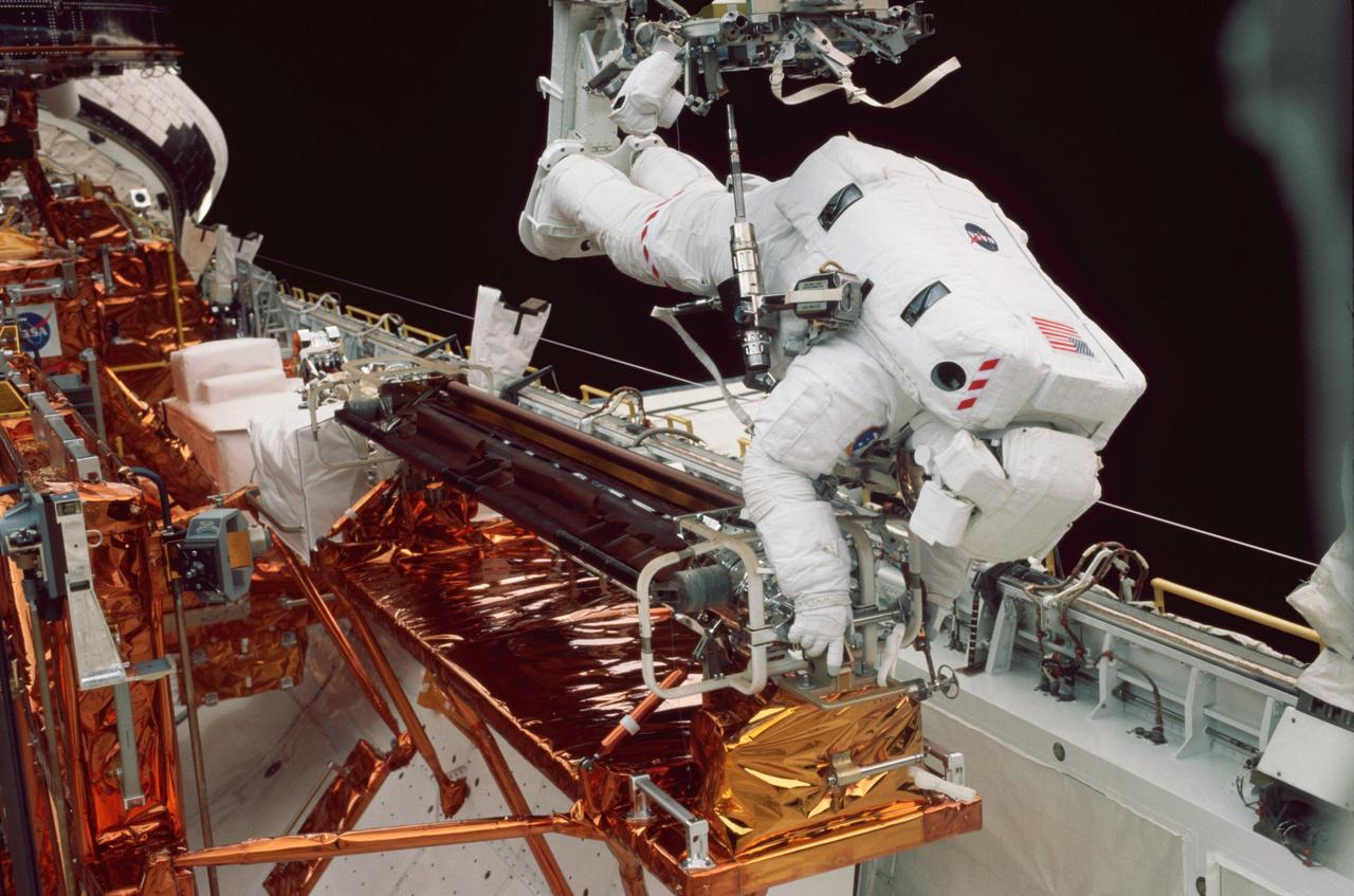
STS-109 Astronaut Michael J. Massimino, mission specialist, perched on the Shuttle's robotic arm is working at the stowage area for the Hubble Space Telescope's port side solar array. Working in tandem with James. H. Newman, Massimino removed the old port solar array and stored it in Columbia's payload bay for return to Earth. The two went on to install a third generation solar array and its associated electrical components. Two crew mates had accomplished the same feat with the starboard array on the previous day. In addition to the replacement of the solar arrays, the STS-109 crew also installed the experimental cooling system for the Hubble's Near-Infrared Camera (NICMOS), replaced the power control unit (PCU), and replaced the Faint Object Camera (FOC) with a new advanced camera for Surveys (ACS). The 108th flight overall in NASA's Space Shuttle Program, the Space Shuttle Columbia STS-109 mission lifted off March 1, 2002 for 10 days, 22 hours, and 11 minutes. Five space walks were conducted to complete the HST upgrades. The Marshall Space Flight Center in Huntsville, Alabama had the responsibility for the design, development, and construction of the HST, which is the most powerful and sophisticated telescope ever built.
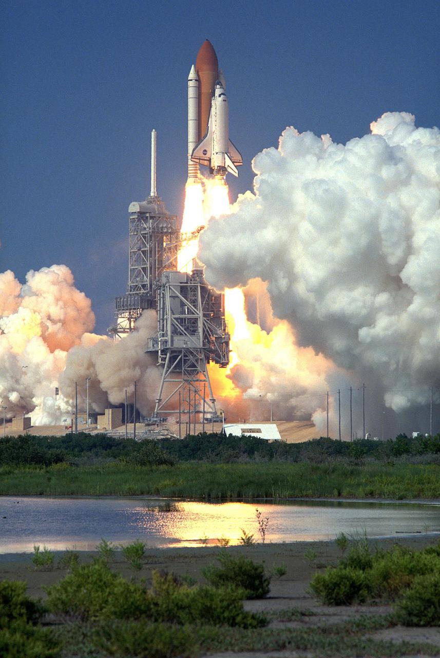
KENNEDY SPACE CENTER, Fla. -- Smoke billows out from Launch Pad 39A as Space Shuttle Discovery soars into the blue sky on mission STS-105 to the International Space Station. Liftoff occurred at 5:10:14 p.m. EDT on this second launch attempt. Launch countdown activities for the 12-day mission were called off Aug. 9 during the T-9 minute hold due to the high potential for lightning, a thick cloud cover and the potential for showers. Besides the Shuttle crew of four, Discovery carries the Expedition Three crew who will replace Expedition Two on the International Space Station. The mission includes the third flight of an Italian-built Multi-Purpose Logistics Module delivering additional scientific racks, equipment and supplies for the Space Station, and two spacewalks. Part of the payload is the Early Ammonia Servicer (EAS) tank, which will be attached to the Station during the spacewalks. The EAS contains spare ammonia for the Station’s cooling system. The three-member Expedition Two crew will be returning to Earth aboard Discovery after a five-month stay on the Station
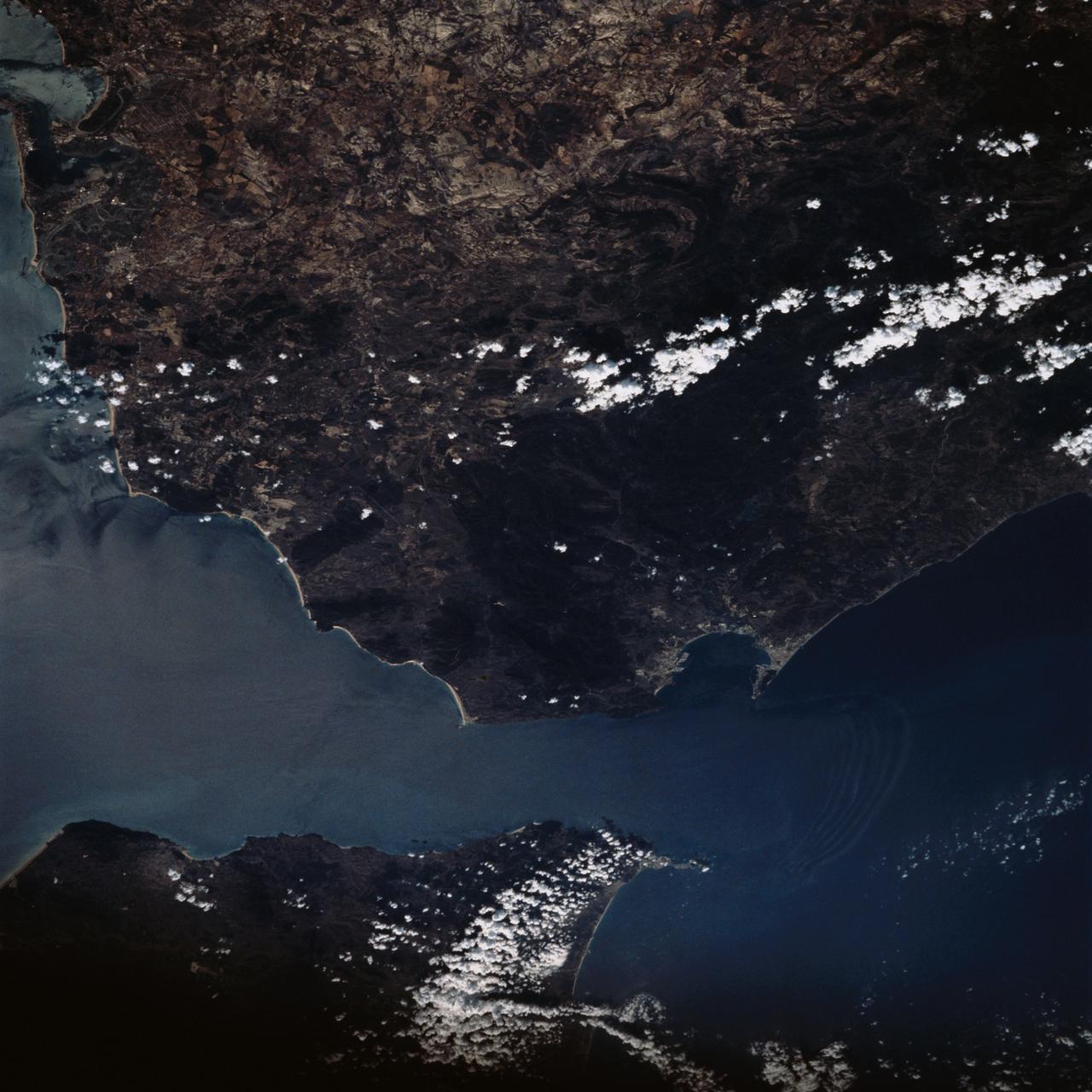
STS058-73-009 (18 Oct-1 Nov 1993) --- Atlantic water flowing with the tide through the Strait of Gibraltar into the Mediterranean generates internal waves as depicted in this photo. The incoming cool, less dense Atlantic water flows over the warm, more saline Mediterranean water. As the tide moves into the Strait of Gibraltar it encounters the Camarinal Sill, which is like a cliff under water, south of Camarinal Point, Spain. Internal waves are generated at the Sill and travel along the density boundary between the Atlantic water and the Mediterranean water. Internal waves have very little effect on the sea surface, except for gentle slopes and slight differences in roughness. We can see them in the Space Shuttle photos because of sunglint which reflects off the water. Internal waves smooth out some of the capillary waves at the surface in bands. The sun reflects more brightly from these smooth areas showing us the pattern of the underwater waves. The Bay of Cadiz on the southwest coast of Spain, the Rock of Gibraltar, and the Moroccan coast are also visible in this photo.
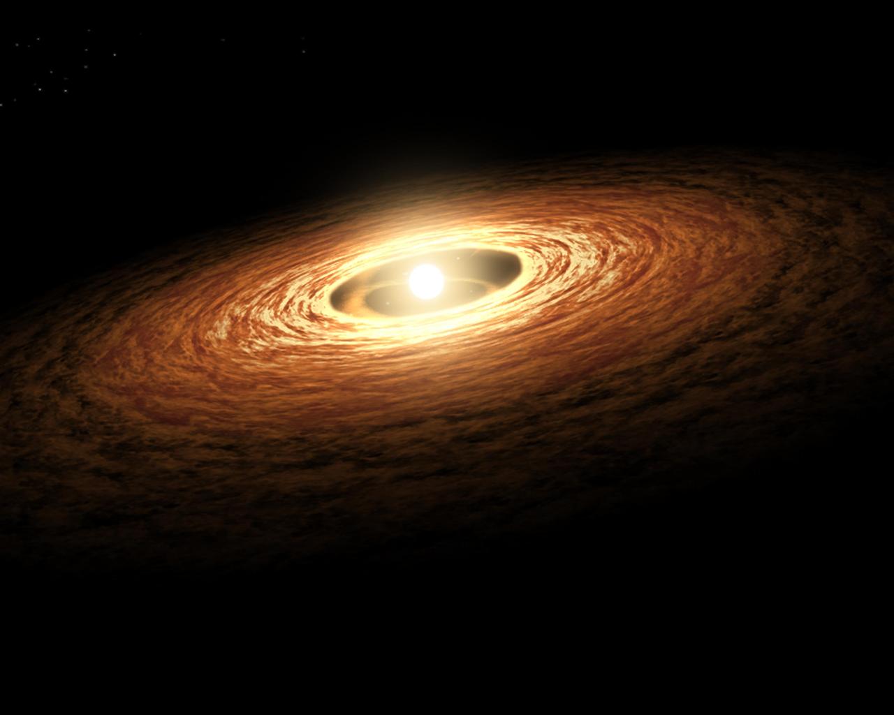
This artist's concept illustrates how silicate crystals like those found in comets can be created by an outburst from a growing star. The image shows a young sun-like star encircled by its planet-forming disk of gas and dust. The silicate that makes up most of the dust would have begun as non-crystallized, amorphous particles. Streams of material are seen spiraling from the disk onto the star increasing its mass and causing the star to brighten and heat up dramatically. The outburst causes temperatures to rise in the star's surrounding disk. The animation (figure 1) zooms into the disk to show close-ups of silicate particles. When the disk warms from the star's outburst, the amorphous particles of silicate melt. As they cool off, they transform into forsterite (figure 2), a type of silicate crystal often found in comets in our solar system. In April 2008, NASA's Spitzer Space Telescope detected evidence of this process taking place on the disk of a young sun-like star called EX Lupi. http://photojournal.jpl.nasa.gov/catalog/PIA12008
KENNEDY SPACE CENTER, Fla. - The Rotating Service Structure has rolled back to launch position for the second time in two days after a scrub of mission STS-109 the day before. NASA managers had determined the unseasonably cold weather predicted at launch time was at the margin of acceptable limits. This view shows Space Shuttle Columbia atop the Mobile Launcher Platform (MLP) on Launch Pad 39A. Twin solid rocket boosters flank the orange-colored external tank. Above the tank is the 'beanie cap,' the gaseous oxygen vent hood. Below the MLP is the flame trench that helps deflect the intense heat and flames away from the vehicle as it lifts off. Columbia is rescheduled for launch on mission STS-109 March 1 at 6:22 a.m. EST (11:22 GMT). The 11-day mission will provide maintenance and upgrade to the Hubble Space Telescope, replacing Solar Array 2 with Solar Array 3, replacing the Power Control Unit, installing the ACS (after removing the Faint Object Camera ), the Near Infrared Camera, the Multi-Object Spectrometer (NICMOS) Cooling System, and the New Outer Blanket Layer insulation.
KENNEDY SPACE CENTER, Fla. -- Space Shuttle Discovery hurtles into the heavens to rendezvous with the International Space Station on mission STS-105. Liftoff occurred on time at 5:10:14 p.m. EDT on this second launch attempt. Launch countdown activities for the 12-day mission were called off Aug. 9 during the T-9 minute hold due to the high potential for lightning, a thick cloud cover and the potential for showers. Besides the Shuttle crew of four, Discovery carries the Expedition Three crew who will replace Expedition Two on the International Space Station. The mission includes the third flight of an Italian-built Multi-Purpose Logistics Module delivering additional scientific racks, equipment and supplies for the Space Station, and two spacewalks. Part of the payload is the Early Ammonia Servicer (EAS) tank, which will be attached to the Station during the spacewalks. The EAS contains spare ammonia for the Station’s cooling system. The three-member Expedition Two crew will be returning to Earth aboard Discovery after a five-month stay on the Station. [Photo by Scott Andrews; Nikon D1X camera.
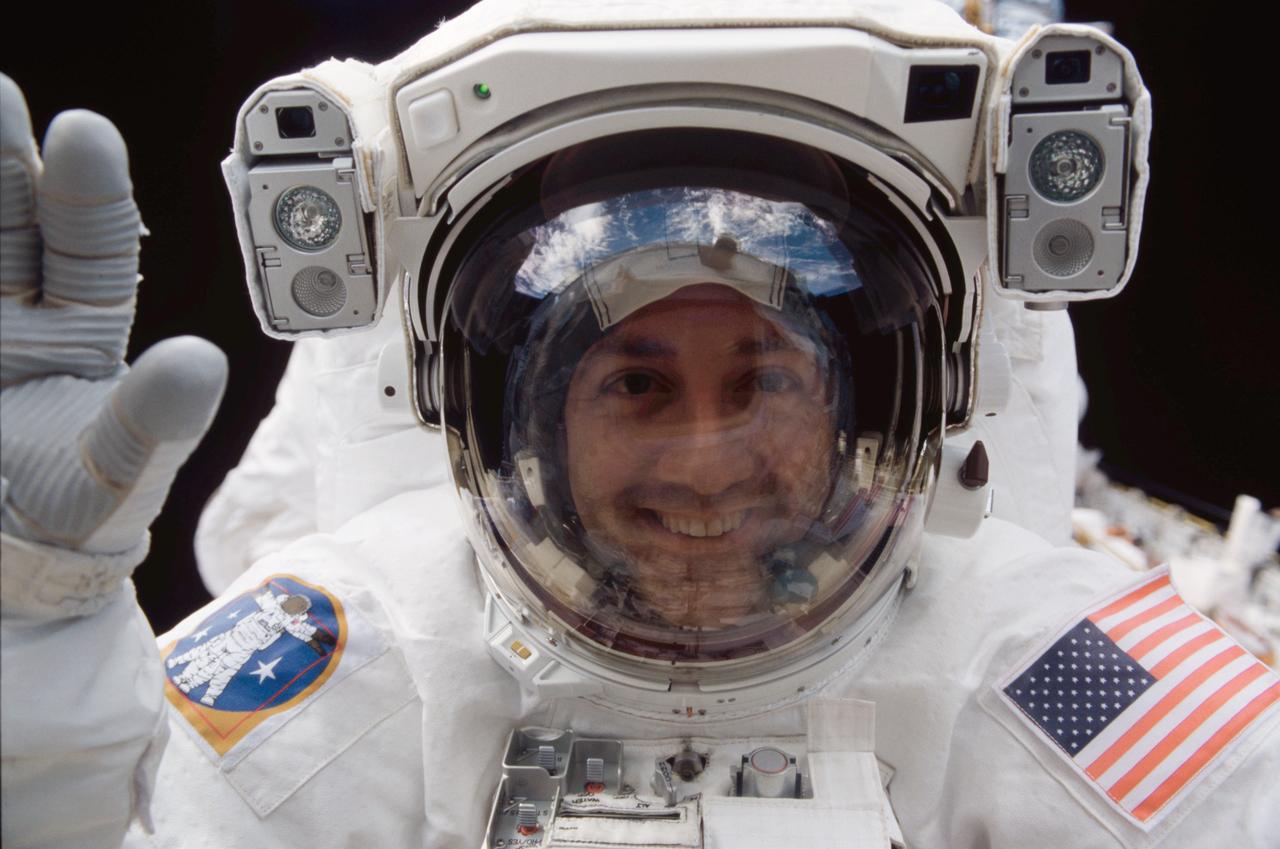
STS-109 Astronauts Michael J. Massimino and James H. Newman were making their second extravehicular activity (EVA) of their mission when astronaut Massimino, mission specialist, peered into Columbia's crew cabin during a brief break from work on the Hubble Space Telescope (HST). The HST is latched down just a few feet behind him in Columbia's cargo bay. The Space Shuttle Columbia STS-109 mission lifted off March 1, 2002 with goals of repairing and upgrading the Hubble Space Telescope (HST). STS-109 upgrades to the HST included: replacement of the solar array panels; replacement of the power control unit (PCU); replacement of the Faint Object Camera (FOC) with a new advanced camera for Surveys (ACS); and installation of the experimental cooling system for the Hubble's Near-Infrared Camera and Multi-object Spectrometer (NICMOS), which had been dormant since January 1999 when its original coolant ran out. The Marshall Space Flight Center in Huntsville, Alabama had the responsibility for the design, development, and construction of the HST, which is the most powerful and sophisticated telescope ever built. Lasting 10 days, 22 hours, and 11 minutes, the STS-109 mission was the 108th flight overall in NASA's Space Shuttle Program.
KENNEDY SPACE CENTER, Fla. -- Space Shuttle Discovery hurtles into the heavens to rendezvous with the International Space Station on mission STS-105. Liftoff occurred on time at 5:10:14 p.m. EDT on this second launch attempt. Launch countdown activities for the 12-day mission were called off Aug. 9 during the T-9 minute hold due to the high potential for lightning, a thick cloud cover and the potential for showers. Besides the Shuttle crew of four, Discovery carries the Expedition Three crew who will replace Expedition Two on the International Space Station. The mission includes the third flight of an Italian-built Multi-Purpose Logistics Module delivering additional scientific racks, equipment and supplies for the Space Station, and two spacewalks. Part of the payload is the Early Ammonia Servicer (EAS) tank, which will be attached to the Station during the spacewalks. The EAS contains spare ammonia for the Station’s cooling system. The three-member Expedition Two crew will be returning to Earth aboard Discovery after a five-month stay on the Station. [Photo by Scott Andrews; Nikon D1X camera

KENNEDY SPACE CENTER, Fla. -- Space Shuttle Discovery hurtles into the heavens to rendezvous with the International Space Station on mission STS-105. Liftoff occurred on time at 5:10:14 p.m. EDT on this second launch attempt. Launch countdown activities for the 12-day mission were called off Aug. 9 during the T-9 minute hold due to the high potential for lightning, a thick cloud cover and the potential for showers. Besides the Shuttle crew of four, Discovery carries the Expedition Three crew who will replace Expedition Two on the International Space Station. The mission includes the third flight of an Italian-built Multi-Purpose Logistics Module delivering additional scientific racks, equipment and supplies for the Space Station, and two spacewalks. Part of the payload is the Early Ammonia Servicer (EAS) tank, which will be attached to the Station during the spacewalks. The EAS contains spare ammonia for the Station’s cooling system. The three-member Expedition Two crew will be returning to Earth aboard Discovery after a five-month stay on the Station. [Photo by Scott Andrews; Nikon D1X camera
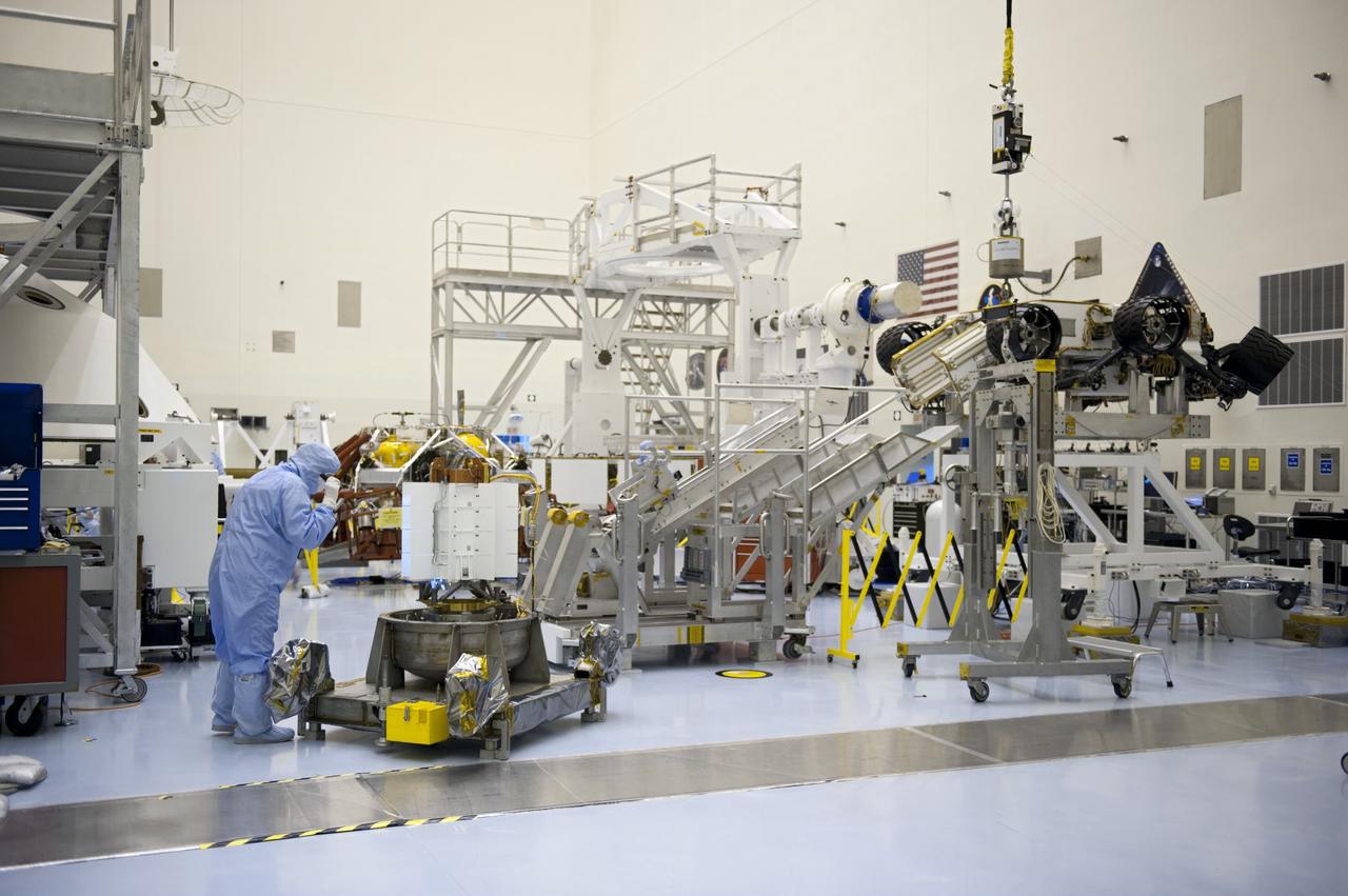
CAPE CANAVERAL, Fla. -- In the high bay of the Payload Hazardous Servicing Facility at NASA's Kennedy Space Center in Florida, a spacecraft technician from NASA's Jet Propulsion Laboratory conducts a visual inspection of the cooling tubes on the exterior of the multi-mission radioisotope thermoelectric generator (MMRTG) for NASA's Mars Science Laboratory (MSL) mission following the MMRTG fit check on the Curiosity rover. At right is the Curiosity rover on an elevated work stand. The MMRTG will generate the power needed for the mission from the natural decay of plutonium-238, a non-weapons-grade form of the radioisotope. Heat given off by this natural decay will provide constant power through the day and night during all seasons. MSL's components include a car-sized rover, Curiosity, which has 10 science instruments designed to search for signs of life, including methane, and help determine if the gas is from a biological or geological source. Waste heat from the MMRTG will be circulated throughout the rover system to keep instruments, computers, mechanical devices and communications systems within their operating temperature ranges. Launch of MSL aboard a United Launch Alliance Atlas V rocket is targeted for Nov. 25 from Space Launch Complex 41 on Cape Canaveral Air Force Station. For more information, visit http://www.nasa.gov/msl. Photo credit: NASA/Kim Shiflett
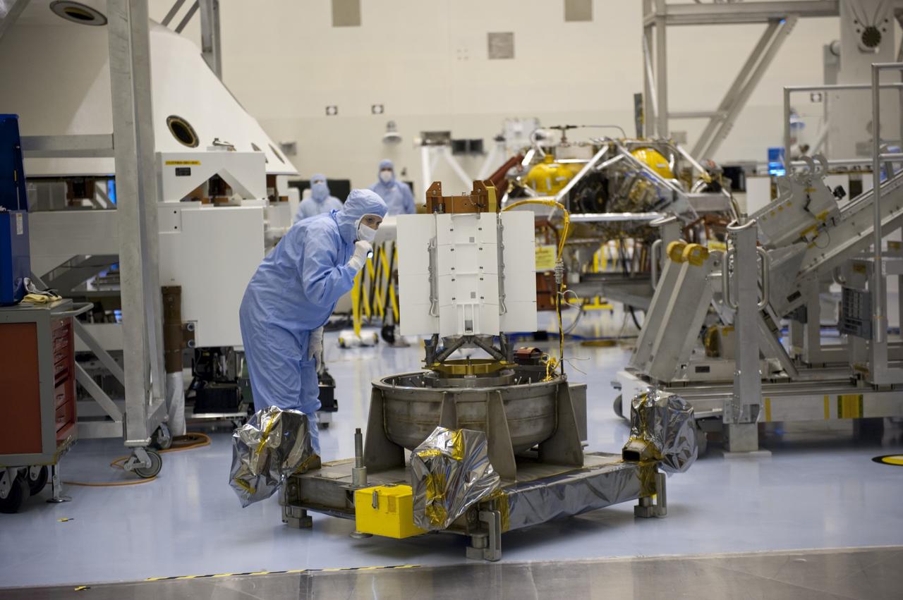
CAPE CANAVERAL, Fla. -- In the high bay of the Payload Hazardous Servicing Facility at NASA's Kennedy Space Center in Florida, a spacecraft technician from NASA's Jet Propulsion Laboratory conducts a visual inspection of the cooling tubes on the exterior of the multi-mission radioisotope thermoelectric generator (MMRTG) for NASA's Mars Science Laboratory (MSL) mission following the MMRTG fit check on the Curiosity rover. The MMRTG will generate the power needed for the mission from the natural decay of plutonium-238, a non-weapons-grade form of the radioisotope. Heat given off by this natural decay will provide constant power through the day and night during all seasons. MSL's components include a car-sized rover, Curiosity, which has 10 science instruments designed to search for signs of life, including methane, and help determine if the gas is from a biological or geological source. Waste heat from the MMRTG will be circulated throughout the rover system to keep instruments, computers, mechanical devices and communications systems within their operating temperature ranges. Launch of MSL aboard a United Launch Alliance Atlas V rocket is targeted for Nov. 25 from Space Launch Complex 41 on Cape Canaveral Air Force Station. For more information, visit http://www.nasa.gov/msl. Photo credit: NASA/Kim Shiflett
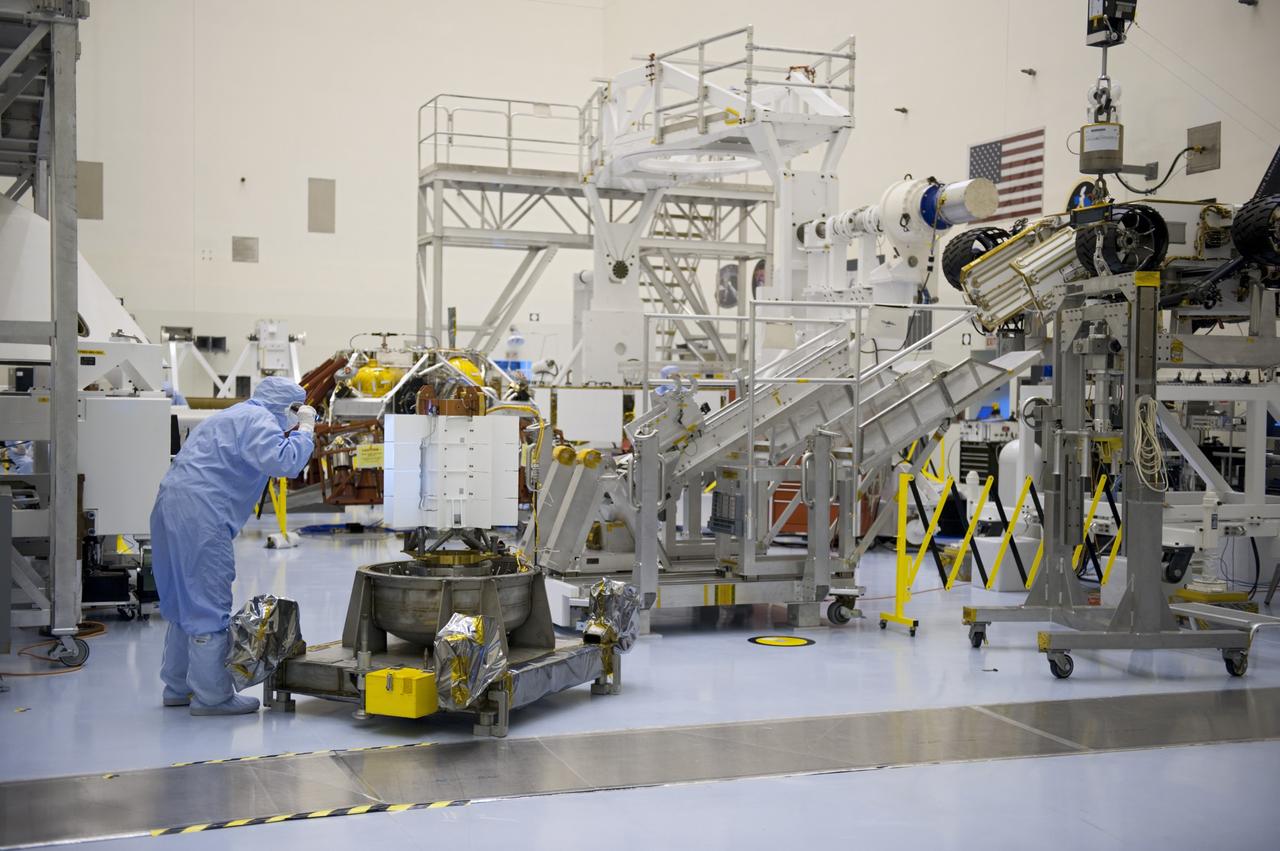
CAPE CANAVERAL, Fla. -- In the high bay of the Payload Hazardous Servicing Facility at NASA's Kennedy Space Center in Florida, a spacecraft technician from NASA's Jet Propulsion Laboratory conducts a visual inspection of the cooling tubes on the exterior of the multi-mission radioisotope thermoelectric generator (MMRTG) for NASA's Mars Science Laboratory (MSL) mission following the MMRTG fit check on the Curiosity rover. At right is the Curiosity rover on an elevated work stand. The MMRTG will generate the power needed for the mission from the natural decay of plutonium-238, a non-weapons-grade form of the radioisotope. Heat given off by this natural decay will provide constant power through the day and night during all seasons. MSL's components include a car-sized rover, Curiosity, which has 10 science instruments designed to search for signs of life, including methane, and help determine if the gas is from a biological or geological source. Waste heat from the MMRTG will be circulated throughout the rover system to keep instruments, computers, mechanical devices and communications systems within their operating temperature ranges. Launch of MSL aboard a United Launch Alliance Atlas V rocket is targeted for Nov. 25 from Space Launch Complex 41 on Cape Canaveral Air Force Station. For more information, visit http://www.nasa.gov/msl. Photo credit: NASA/Kim Shiflett
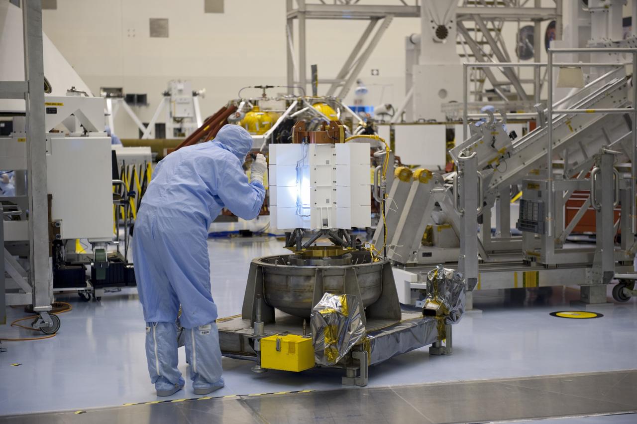
CAPE CANAVERAL, Fla. -- In the high bay of the Payload Hazardous Servicing Facility at NASA's Kennedy Space Center in Florida, a spacecraft technician from NASA's Jet Propulsion Laboratory conducts a visual inspection of the cooling tubes on the exterior of the multi-mission radioisotope thermoelectric generator (MMRTG) for NASA's Mars Science Laboratory (MSL) mission following the MMRTG fit check on the Curiosity rover. The MMRTG will generate the power needed for the mission from the natural decay of plutonium-238, a non-weapons-grade form of the radioisotope. Heat given off by this natural decay will provide constant power through the day and night during all seasons. MSL's components include a car-sized rover, Curiosity, which has 10 science instruments designed to search for signs of life, including methane, and help determine if the gas is from a biological or geological source. Waste heat from the MMRTG will be circulated throughout the rover system to keep instruments, computers, mechanical devices and communications systems within their operating temperature ranges. Launch of MSL aboard a United Launch Alliance Atlas V rocket is targeted for Nov. 25 from Space Launch Complex 41 on Cape Canaveral Air Force Station. For more information, visit http://www.nasa.gov/msl. Photo credit: NASA/Kim Shiflett
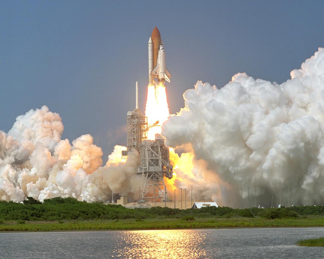
KENNEDY SPACE CENTER, Fla. -- Space Shuttle Discovery clears the lightning rod on Launch Pad 39A as it soars into the blue sky on mission STS-105 to the International Space Station. Liftoff occurred at 5:10:14 p.m. EDT on this second launch attempt. Launch countdown activities for the 12-day mission were called off Aug. 9 during the T-9 minute hold due to the high potential for lightning, a thick cloud cover and the potential for showers. Besides the Shuttle crew of four, Discovery carries the Expedition Three crew who will replace Expedition Two on the International Space Station. The mission includes the third flight of an Italian-built Multi-Purpose Logistics Module delivering additional scientific racks, equipment and supplies for the Space Station, and two spacewalks. Part of the payload is the Early Ammonia Servicer (EAS) tank, which will be attached to the Station during the spacewalks. The EAS contains spare ammonia for the Station’s cooling system. The three-member Expedition Two crew will be returning to Earth aboard Discovery after a five-month stay on the Station
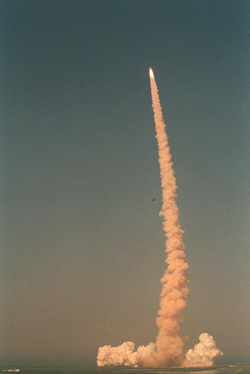
KENNEDY SPACE CENTER, Fla. -- Trailing a fiery-looking column of smoke, Space Shuttle Discovery hurtles into a blue sky on mission STS-105 to the International Space Station. Viewed from the top of the Vehicle Assembly Building, liftoff occurred at 5:10:14 p.m. EDT on this second launch attempt. Launch countdown activities for the 12-day mission were called off Aug. 9 during the T-9 minute hold due to the high potential for lightning, a thick cloud cover and the potential for showers. Besides the Shuttle crew of four, Discovery carries the Expedition Three crew who will replace Expedition Two on the International Space Station. The mission includes the third flight of an Italian-built Multi-Purpose Logistics Module delivering additional scientific racks, equipment and supplies for the Space Station, and two spacewalks. Part of the payload is the Early Ammonia Servicer (EAS) tank, which will be attached to the Station during the spacewalks. The EAS contains spare ammonia for the Station’s cooling system. The three-member Expedition Two crew will be returning to Earth aboard Discovery after a five-month stay on the Station
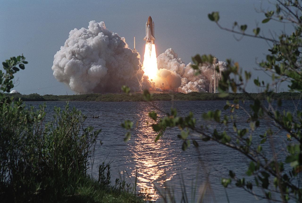
The Space Shuttle Orbiter Atlantis STS-110, embarking on its 25th flight, lifts off from launch pad 39B at Kennedy Space Center at 3:44 p.m. CDT April 8, 2002. The STS-110 mission prepared the International Space Station (ISS) for future space walks by installing and outfitting a 43-foot-long Starboard side S0 truss and preparing the Mobile Transporter. The 27,000 pound S0 Truss was the first of 9 segments that will make up the Station's external framework that will eventually stretch 356 feet (109 meters), or approximately the length of a football field. This central truss segment also includes a flatcar called the Mobile Transporter and rails that will become the first "space railroad," which will allow the Station's robotic arm to travel up and down the finished truss for future assembly and maintenance. The completed truss structure will hold solar arrays and radiators to provide power and cooling for additional international research laboratories from Japan and Europe that will be attached to the Station. Milestones of the S-110 mission included the first time the ISS robotic arm was used to maneuver space walkers around the Station and marked the first time all space walks were based out of the Station's Quest Airlock. It was also the first Shuttle to use three Block II Main Engines.
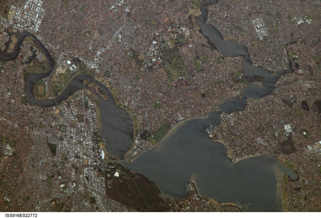
ISS016-E-022772 (11 Jan. 2008) --- Perth, Australia is featured in this image photographed by an Expedition 16 crewmember on the International Space Station (ISS). Perth is the capital of the state of Western Australia, and the largest city of the southwestern continent of Australia with an estimated population of over 1.5 million (December 2006). The downtown area of Perth and the surrounding suburbs are located on flood plain deposits of the Swan and Canning Rivers that flow through the center of the metropolitan area. Perth enjoys a Mediterranean climate, where the summers are hot and dry and winters are cool and moist. Wildfires can develop during the summer months; several large fires threatened the eastern portion of the metropolitan area in 2005. This view captures variations in urban land cover in the visible wavelengths to which the human eye is sensitive (visible red, green, and blue). The downtown center of Perth at left is characterized by large buildings (such as skyscrapers) with white reflective rooftops. Suburbs to the south (across the Swan River) are characterized by higher density of small buildings with predominantly reddish-purple roofs. Several areas of green vegetation are visible in the image. Parks and golf courses comprised mainly of grass present an even green coloration, while the dense tree canopy of Kings Park appears dark green. Variations in the coloration of the Swan and Canning Rivers is due to sunglint, or light reflected off the water surface back to the observer (in this case, a crewmember onboard the ISS).

KENNEDY SPACE CENTER, Fla. -- Space Shuttle Discovery hurtles into the heavens to rendezvous with the International Space Station on mission STS-105. Liftoff occurred on time at 5:10:14 p.m. EDT on this second launch attempt. Launch countdown activities for the 12-day mission were called off Aug. 9 during the T-9 minute hold due to the high potential for lightning, a thick cloud cover and the potential for showers. Besides the Shuttle crew of four, Discovery carries the Expedition Three crew who will replace Expedition Two on the International Space Station. The mission includes the third flight of an Italian-built Multi-Purpose Logistics Module delivering additional scientific racks, equipment and supplies for the Space Station, and two spacewalks. Part of the payload is the Early Ammonia Servicer (EAS) tank, which will be attached to the Station during the spacewalks. The EAS contains spare ammonia for the Station’s cooling system. The three-member Expedition Two crew will be returning to Earth aboard Discovery after a five-month stay on the Station. [Photo by Scott Andrews; Nikon D1X camera.
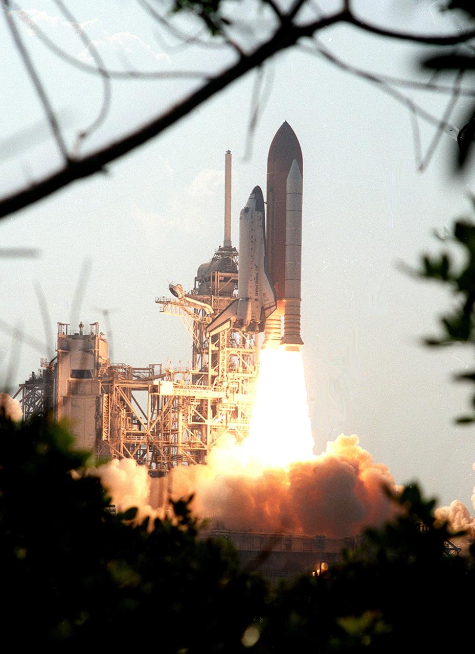
KENNEDY SPACE CENTER, Fla. -- Viewed from between the trees, Space Shuttle Discovery rises above the smoke as it soars into the blue sky on mission STS-105 to the International Space Station. Viewed from the top of the Vehicle Assembly Building, liftoff occurred at 5:10:14 p.m. EDT on this second launch attempt. Launch countdown activities for the 12-day mission were called off Aug. 9 during the T-9 minute hold due to the high potential for lightning, a thick cloud cover and the potential for showers. Besides the Shuttle crew of four, Discovery carries the Expedition Three crew who will replace Expedition Two on the International Space Station. The mission includes the third flight of an Italian-built Multi-Purpose Logistics Module delivering additional scientific racks, equipment and supplies for the Space Station, and two spacewalks. Part of the payload is the Early Ammonia Servicer (EAS) tank, which will be attached to the Station during the spacewalks. The EAS contains spare ammonia for the Station’s cooling system. The three-member Expedition Two crew will be returning to Earth aboard Discovery after a five-month stay on the Station
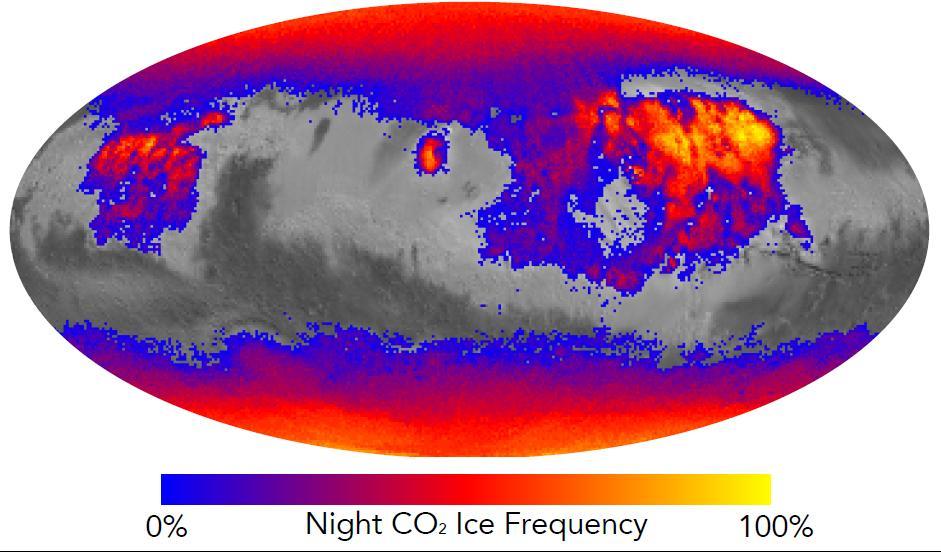
This map shows the frequency of carbon dioxide frost's presence at sunrise on Mars, as a percentage of days year-round. Carbon dioxide ice more often covers the ground at night in some mid-latitude regions than in polar regions, where it is generally absent for much of summer and fall. Color coding is based on data from the Mars Climate Sounder instrument on NASA's Mars Reconnaissance Orbiter. A color-key bar below the map shows how colors correspond to frequencies. Yellow indicates high frequencies, identifying areas where carbon dioxide ice is present on the ground at night during most of the year. Blue identifies areas where it is rarely present; red is intermediate. Areas without color coding are regions where carbon dioxide frost is not detected at any time of year. The areas with highest frequency of overnight carbon dioxide frost correspond to regions with surfaces of loose dust, which do not retain heat well, compared to rockier areas. Those areas also have some of the highest mid-afternoon temperatures on the planet. The dust surface heats up and cools off rapidly. http://photojournal.jpl.nasa.gov/catalog/PIA20758
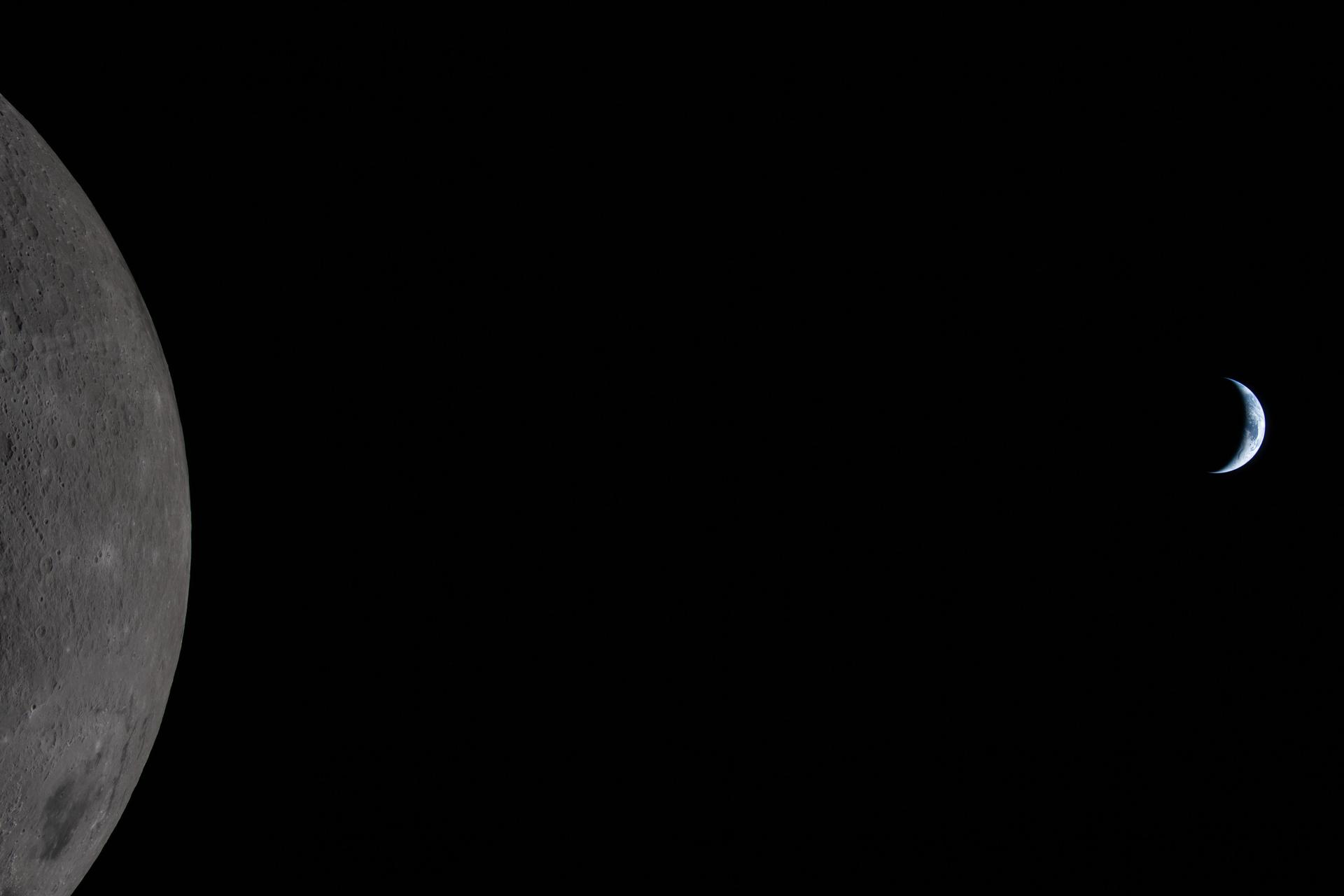
art002e009284 (April 6, 2026) – Earth appears tiny as the Moon looms large in this photo taken by the Artemis II crew during their lunar flyby on April 6, 2026. Taken 36 minutes before Earthset, our home planet is visible in the blackness of space off the limb of the illuminated Moon. Earth is in a crescent phase, with sunlight coming from the right. Orientale mare basin, with its dark floor of cooled lava and outer rings of mountains, covers nearly the lower third of the imaged lunar surface. Different colors in the mare hint at its mineral composition. The lines of small indentations above Orientale are secondary crater chains, formed by material ejected during a violent primary impact. Both of the new craters that the Artemis II crew has suggested names for – Integrity and Carroll – are in full view. The edge of the visible surface of the Moon is called the “lunar limb.” Seen from afar, it almost looks like a circular arc – except when backlit, as in other images captured by the Artemis II crew.
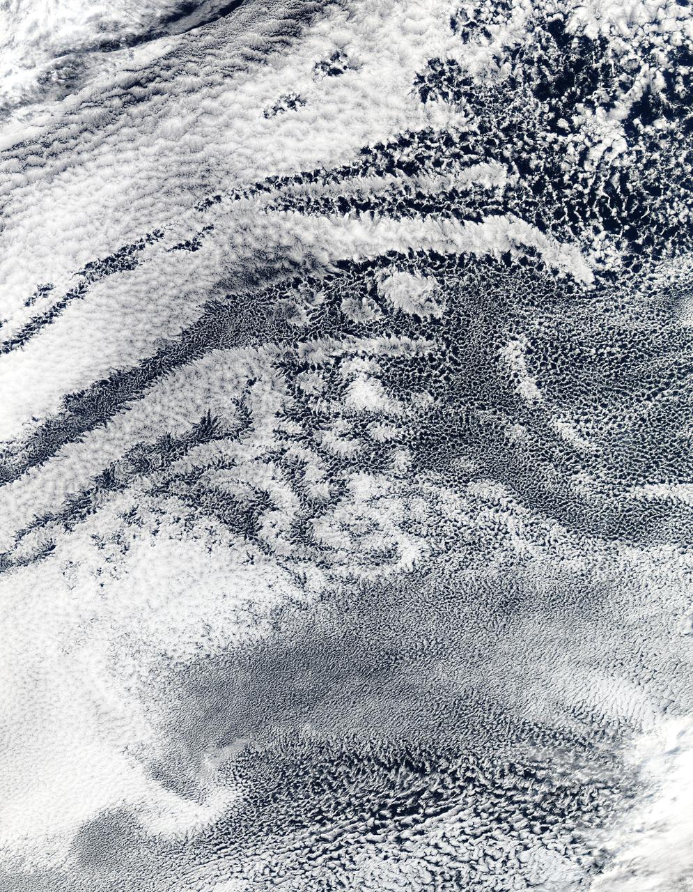
2010/107 - 04/17 at 21 :05 UTC. Open-cell and closed-cell clouds off Peru, Pacific Ocean Resembling a frosted window on a cold winter's day, this lacy pattern of marine clouds was captured off the coast of Peru in the Pacific Ocean by the MODIS on the Aqua satellite on April 19, 2010. The image reveals both open- and closed-cell cumulus cloud patterns. These cells, or parcels of air, often occur in roughly hexagonal arrays in a layer of fluid (the atmosphere often behaves like a fluid) that begins to "boil," or convect, due to heating at the base or cooling at the top of the layer. In "closed" cells warm air is rising in the center, and sinking around the edges, so clouds appear in cell centers, but evaporate around cell edges. This produces cloud formations like those that dominate the lower left. The reverse flow can also occur: air can sink in the center of the cell and rise at the edge. This process is called "open cell" convection, and clouds form at cell edges around open centers, which creates a lacy, hollow-looking pattern like the clouds in the upper right. Closed and open cell convection represent two stable atmospheric configurations — two sides of the convection coin. But what determines which path the "boiling" atmosphere will take? Apparently the process is highly chaotic, and there appears to be no way to predict whether convection will result in open or closed cells. Indeed, the atmosphere may sometimes flip between one mode and another in no predictable pattern. Satellite: Aqua NASA/GSFC/Jeff Schmaltz/MODIS Land Rapid Response Team To learn more about MODIS go to: <a href="http://rapidfire.sci.gsfc.nasa.gov/gallery/?latest" rel="nofollow">rapidfire.sci.gsfc.nasa.gov/gallery/?latest</a> <b><a href="http://www.nasa.gov/centers/goddard/home/index.html" rel="nofollow">NASA Goddard Space Flight Center</a></b> is home to the nation's largest organization of combined scientists, engineers and technologists that build spacecraft, instruments and new technology to study the Earth, the sun, our solar system, and the universe.
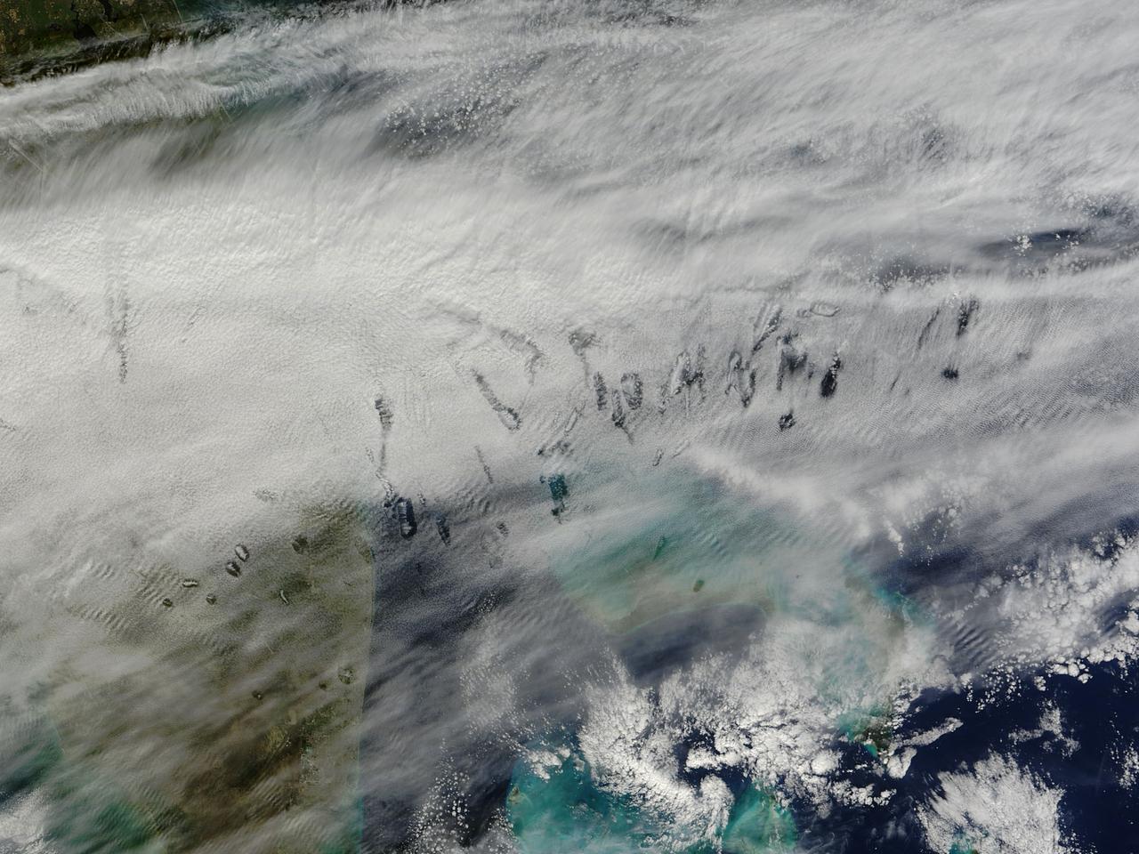
In elementary school, students learn that water freezes at 0 degrees Celsius (32 degrees Fahrenheit). That is true most of the time, but there are exceptions to the rule. For instance, water with very few impurities (such as dust or pollution particles, fungal spores, bacteria) can be chilled to much cooler temperatures and still remain liquid—a process known as supercooling. Supercooling may sound exotic, but it occurs pretty routinely in Earth’s atmosphere. Altocumulus clouds, a common type of mid-altitude cloud, are mostly composed of water droplets supercooled to a temperature of about -15 degrees C. Altocumulus clouds with supercooled tops cover about 8 percent of Earth’s surface at any given time. Supercooled water droplets play a key role in the formation of hole-punch and canal clouds, the distinctive clouds shown in these satellite images. Hole-punch clouds usually appear as circular gaps in decks of altocumulus clouds; canal clouds look similar but the gaps are longer and thinner. This true-color image shows hole-punch and canal clouds off the coast of Florida, as observed on December 12, 2014, by the Moderate Resolution Imaging Spectroradiometer (MODIS) on NASA’s Terra satellite. Both types of cloud form when aircraft fly through cloud decks rich with supercooled water droplets and produce aerodynamic contrails. Air expands and cools as it moves around the wings and past the propeller, a process known as adiabatic cooling. Air temperatures over jet wings often cool by as much as 20 degrees Celsius, pushing supercooled water droplets to the point of freezing. As ice crystals form, they absorb nearby water droplets. Since ice crystals are relatively heavy, they tend to sink. This triggers tiny bursts of snow or rain that leave gaps in the cloud cover. Whether a cloud formation becomes a hole-punch or canal depends on the thickness of the cloud layer, the air temperature, and the degree of horizontal wind shear. Both descending and ascending aircraft—including jets and propeller planes—can trigger hole-punch and canal clouds. The nearest major airports in the images above include Miami International, Fort Lauderdale International, Grand Bahama International, and Palm Beach International. Credit: NASA/GSFC/Jeff Schmaltz/MODIS Land Rapid Response Team <b><a href="http://www.nasa.gov/audience/formedia/features/MP_Photo_Guidelines.html" rel="nofollow">NASA image use policy.</a></b> <b><a href="http://www.nasa.gov/centers/goddard/home/index.html" rel="nofollow">NASA Goddard Space Flight Center</a></b> enables NASA’s mission through four scientific endeavors: Earth Science, Heliophysics, Solar System Exploration, and Astrophysics. Goddard plays a leading role in NASA’s accomplishments by contributing compelling scientific knowledge to advance the Agency’s mission. <b>Follow us on <a href="http://twitter.com/NASAGoddardPix" rel="nofollow">Twitter</a></b> <b>Like us on <a href="http://www.facebook.com/pages/Greenbelt-MD/NASA-Goddard/395013845897?ref=tsd" rel="nofollow">Facebook</a></b> <b>Find us on <a href="http://instagram.com/nasagoddard?vm=grid" rel="nofollow">Instagram</a></b>
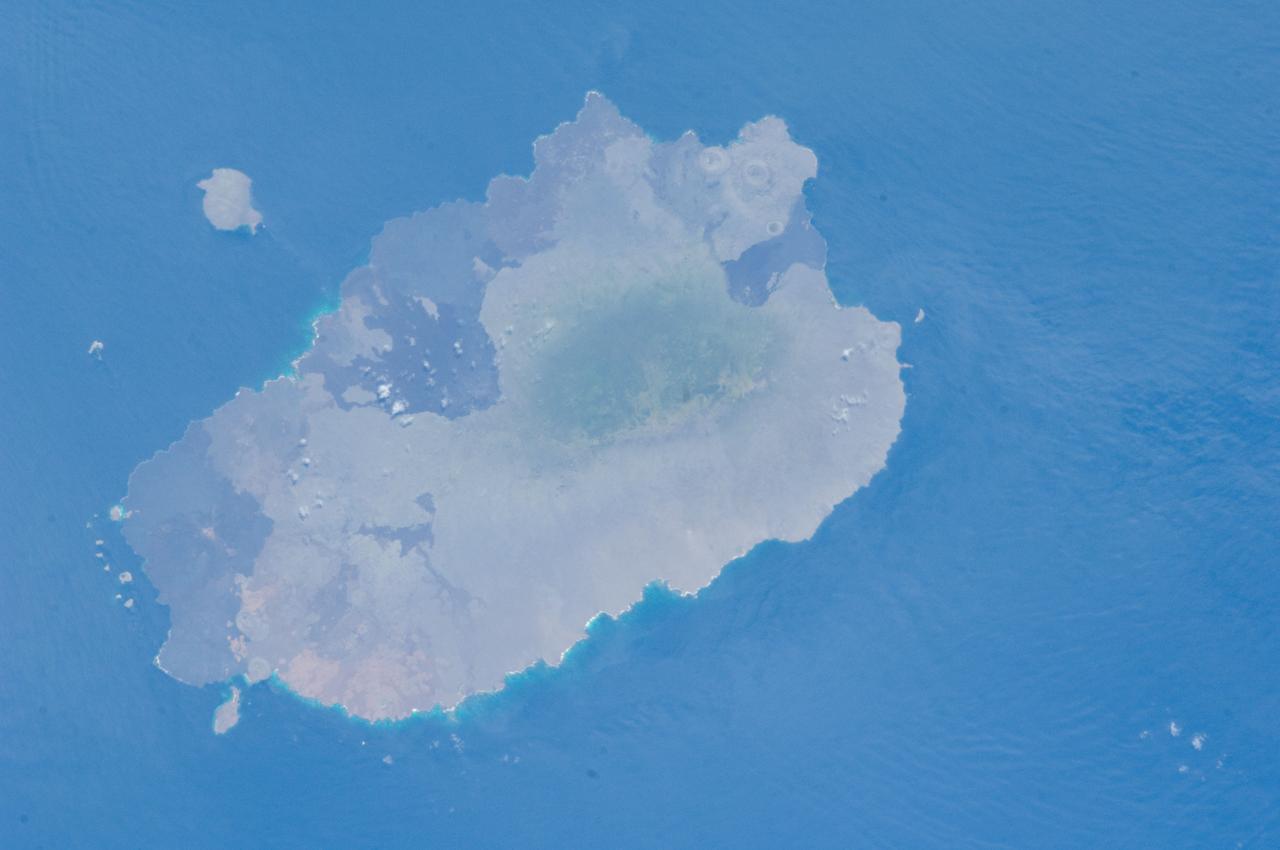
ISS033-E-012648 (18 Oct. 2012) --- Isla Santiago is featured in this image photographed by an Expedition 33 crew member on the International Space Station. The island of Santiago is located near the center of the Galapagos Islands off the coast of Ecuador. The Galapagos Islands are situated near the equator, and were formed from volcanism related to a large mantle plume (also known as a hot spot). This hot spot is very close to the tectonic boundary between the Galapagos Ridge, a plate boundary that is also an oceanic spreading center, and the Nazca and Cocos plates. This combination of mantle plumes and tectonic plate movements produces a unique geological environment, including underwater ridges of volcanoes that influence the water circulation around the Galapagos. All of these aspects contribute to the geology and biology of the Galapagos. Isla Santiago itself is formed from a shield volcano also called Santiago. This type of volcanic structure is recognized by low, flat summits surrounded by extensive flow fields of lava; the lava is not very viscous, so it can flow for great distances from the source vents. Several dark lava flow fields are visible in this photograph, the largest along the eastern, western, and southern coastlines. The small Isla Rabida to the south of Isla Santiago is the peak of another, mostly submerged shield volcano. In addition to the lava flows, other volcanic features known as tuff cones are visible on the eastern and western sides of the island. These cones are formed from the rapid interaction of hot flowing lava and water. The water underneath the lava flow flashes to steam explosively, and this both fragments the lava and rapidly cools it, leading to the formation of cones of glassy, relatively fine-grained volcanic material. The most recent volcanic activity on Isla Santiago occurred during 1904 – 1906. The summit ridge of the Santiago shield volcano is located in the northwestern part of the island (center). Also at center is a large but isolated region of green vegetation primarily located on the south-facing slope below the summit ridge. This image was taken during the dry, or garua, season that lasts from June to November. The season is dominated by cooler air transported by the Southeast Trade winds and cooler waters from the Humboldt and Cromwell currents. The combination of cool air and water results in rain falling only in the island highlands, with south- and east-facing slopes receiving the most precipitation. Despite the favorable topographic location, the yellow green color of the vegetation may indicate water (or other) stress.
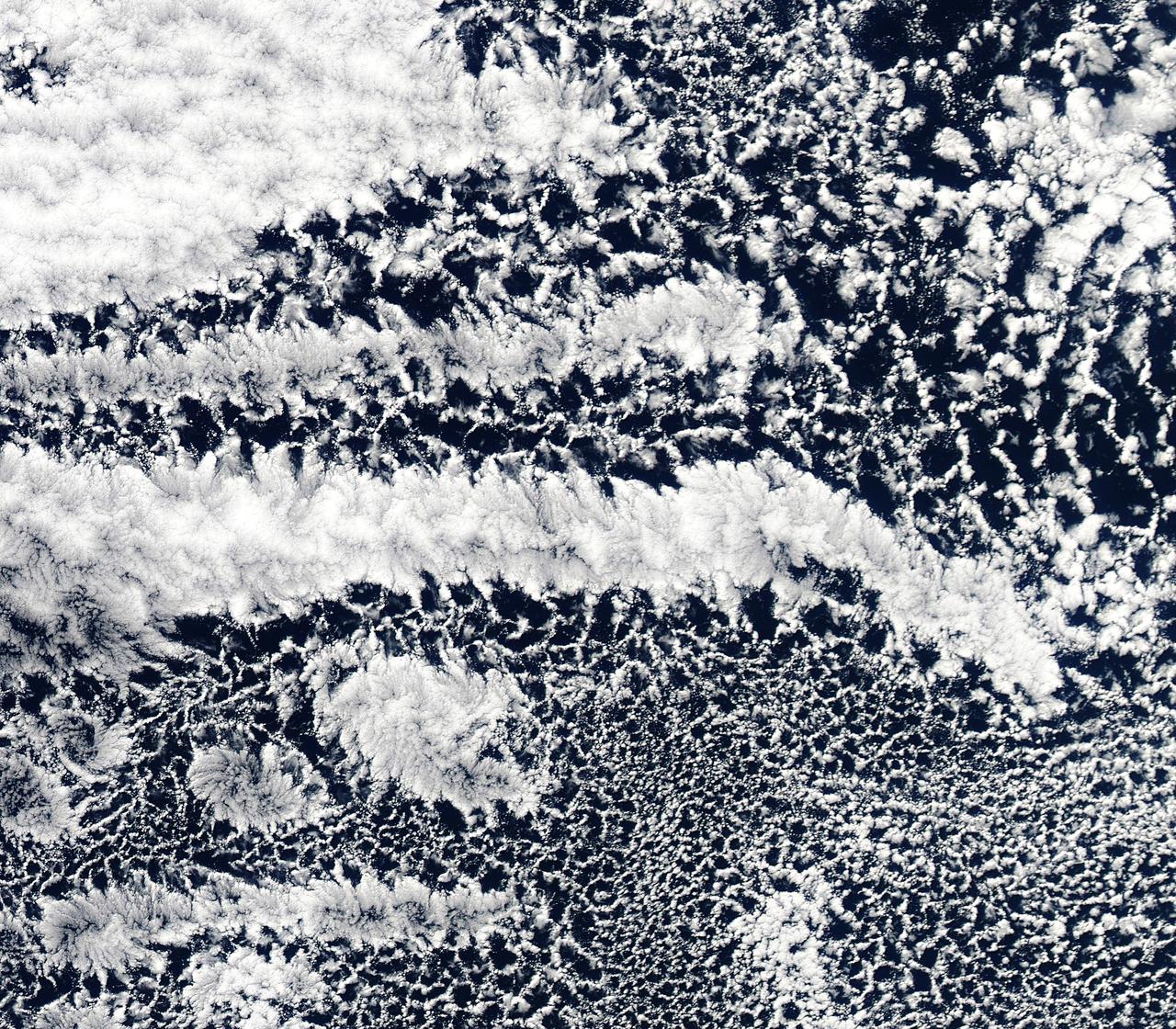
2010/107 - 04/17 at 21 :05 UTC. Open-cell and closed-cell clouds off Peru, Pacific Ocean. To view the full fame of this image to go: <a href="http://www.flickr.com/photos/gsfc/4557497219/">www.flickr.com/photos/gsfc/4557497219/</a> Resembling a frosted window on a cold winter's day, this lacy pattern of marine clouds was captured off the coast of Peru in the Pacific Ocean by the MODIS on the Aqua satellite on April 19, 2010. The image reveals both open- and closed-cell cumulus cloud patterns. These cells, or parcels of air, often occur in roughly hexagonal arrays in a layer of fluid (the atmosphere often behaves like a fluid) that begins to "boil," or convect, due to heating at the base or cooling at the top of the layer. In "closed" cells warm air is rising in the center, and sinking around the edges, so clouds appear in cell centers, but evaporate around cell edges. This produces cloud formations like those that dominate the lower left. The reverse flow can also occur: air can sink in the center of the cell and rise at the edge. This process is called "open cell" convection, and clouds form at cell edges around open centers, which creates a lacy, hollow-looking pattern like the clouds in the upper right. Closed and open cell convection represent two stable atmospheric configurations — two sides of the convection coin. But what determines which path the "boiling" atmosphere will take? Apparently the process is highly chaotic, and there appears to be no way to predict whether convection will result in open or closed cells. Indeed, the atmosphere may sometimes flip between one mode and another in no predictable pattern. Satellite: Aqua NASA/GSFC/Jeff Schmaltz/MODIS Land Rapid Response Team To learn more about MODIS go to: <a href="http://rapidfire.sci.gsfc.nasa.gov/gallery/?latest" rel="nofollow">rapidfire.sci.gsfc.nasa.gov/gallery/?latest</a> <b><a href="http://www.nasa.gov/centers/goddard/home/index.html" rel="nofollow">NASA Goddard Space Flight Center</a></b> is home to the nation's largest organization of combined scientists, engineers and technologists that build spacecraft, instruments and new technology to study the Earth, the sun, our solar system, and the universe.
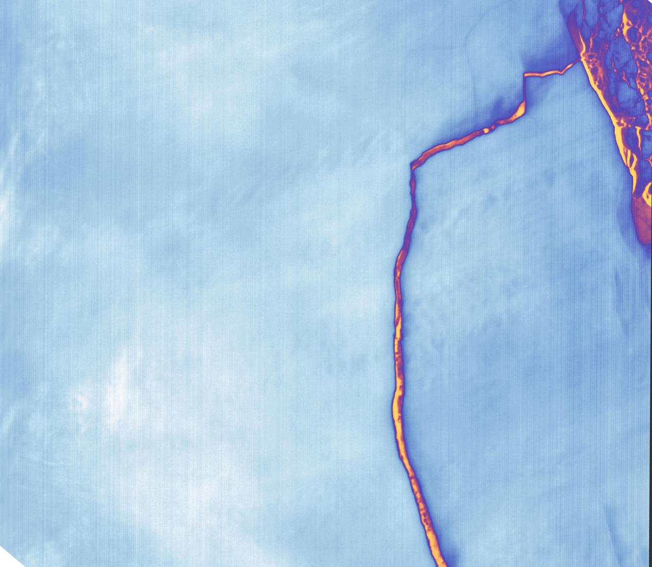
Sometime between July 10 and July 12, an iceberg about the size of Delaware split off from Antarctica’s Larsen C ice shelf. Now that nearly 5,800 square kilometers (2,200 square miles) of ice has broken away, the Larsen C shelf area has shrunk by approximately 10 percent. This false-color image was captured by Landsat’s Thermal Infrared Sensor (TIRS). It shows the relative warmth or coolness of the landscape. Orange indicates where the surface is the warmest, most notably the mélange between the new berg and the ice shelf. Light blues and whites are the coldest areas, including the ice shelf and the iceberg. On July 13, the U.S. National Ice Center issued a press release confirming the new iceberg and officially naming it A-68. Credit: NASA Earth Observatory images by Joshua Stevens, using Landsat data from the U.S. Geological Survey <b><a href="http://www.nasa.gov/audience/formedia/features/MP_Photo_Guidelines.html" rel="nofollow">NASA image use policy.</a></b> <b><a href="http://www.nasa.gov/centers/goddard/home/index.html" rel="nofollow">NASA Goddard Space Flight Center</a></b> enables NASA’s mission through four scientific endeavors: Earth Science, Heliophysics, Solar System Exploration, and Astrophysics. Goddard plays a leading role in NASA’s accomplishments by contributing compelling scientific knowledge to advance the Agency’s mission. <b>Follow us on <a href="http://twitter.com/NASAGoddardPix" rel="nofollow">Twitter</a></b> <b>Like us on <a href="http://www.facebook.com/pages/Greenbelt-MD/NASA-Goddard/395013845897?ref=tsd" rel="nofollow">Facebook</a></b> <b>Find us on <a href="http://instagrid.me/nasagoddard/?vm=grid" rel="nofollow">Instagram</a></b>