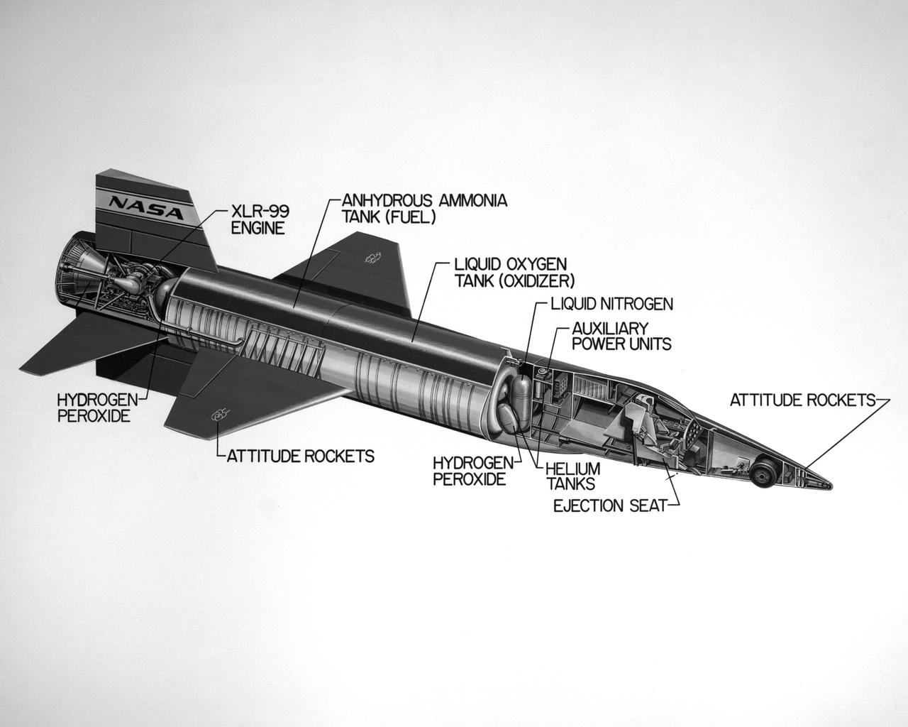
Cutaway drawing of the North American X-15.
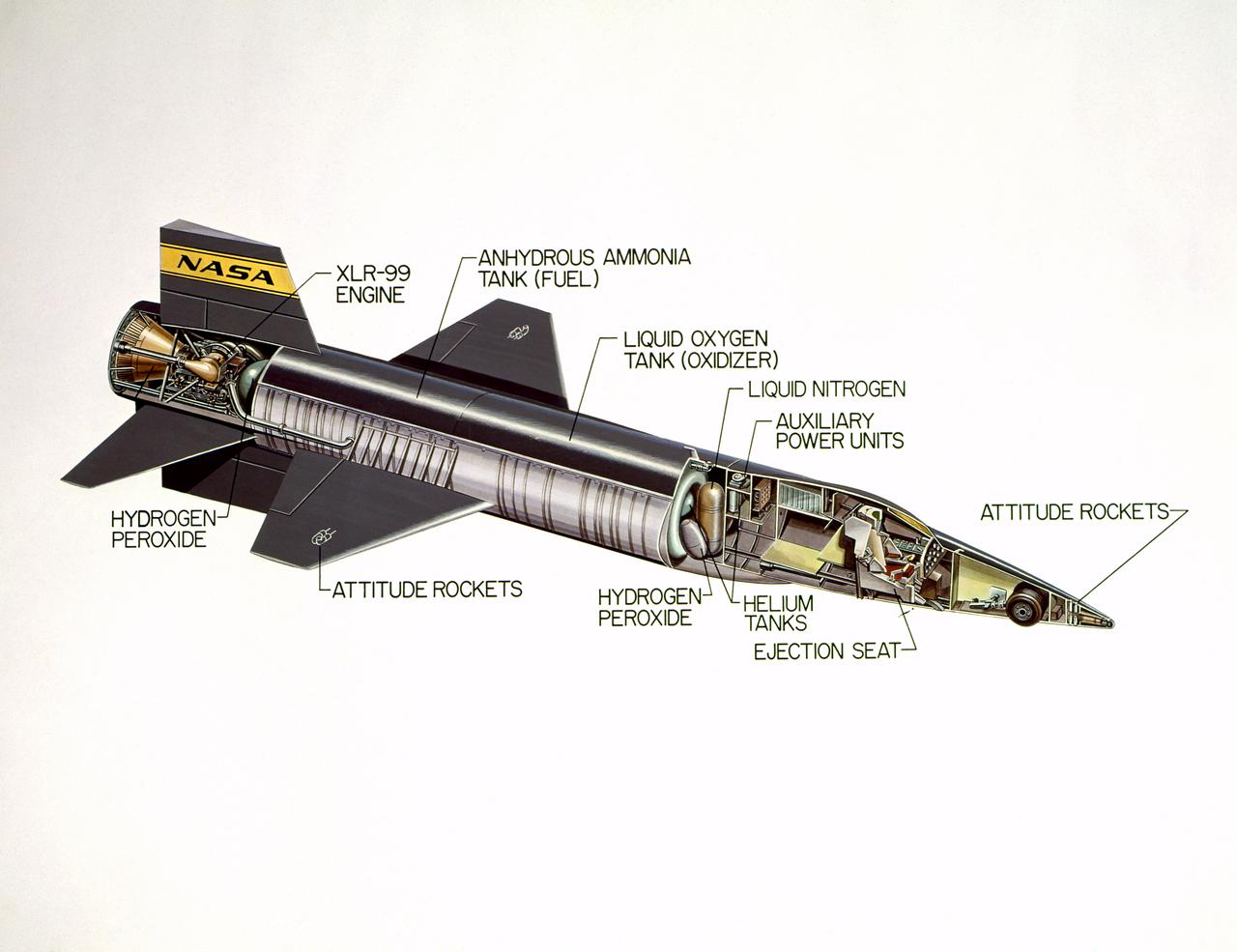
Cutaway drawing of the North American X-15.
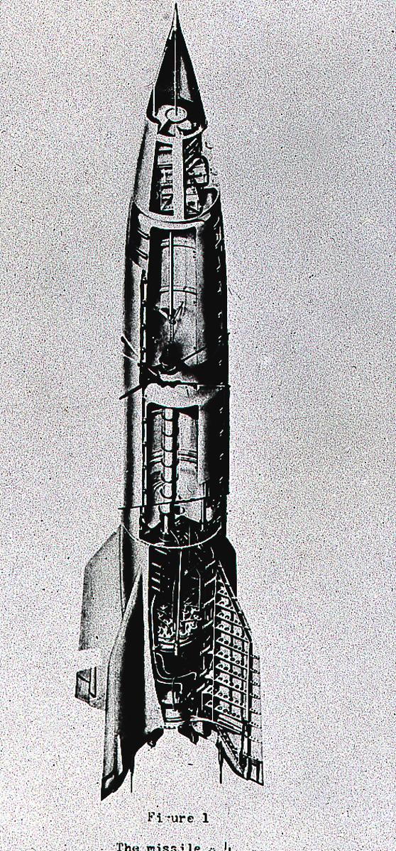
The cutaway drawing of the A-4 (Aggregate-4) rocket. Later renamed the V-2 (Vengeance Weapon-2), The rocket was developed by Dr. Wernher von Braun and the German rocket team at Peenemuende, Germany on the Baltic Sea. At the end of World War II, the team of German engineers and scientists came to the United States and continued rocket research for the Army at Fort Bliss, Texas, and Redstone Arsenal in Huntsville, Alabama.
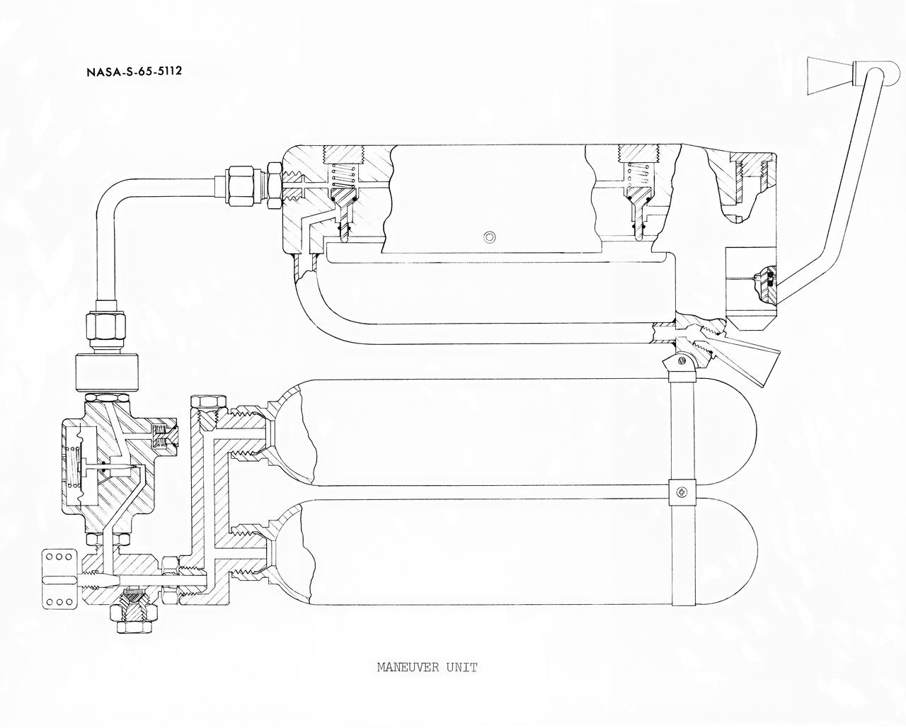
S65-05112 (30 May 1965) --- Cutaway engineering drawing showing some of the features of the zero-gravity integral propulsion unit.
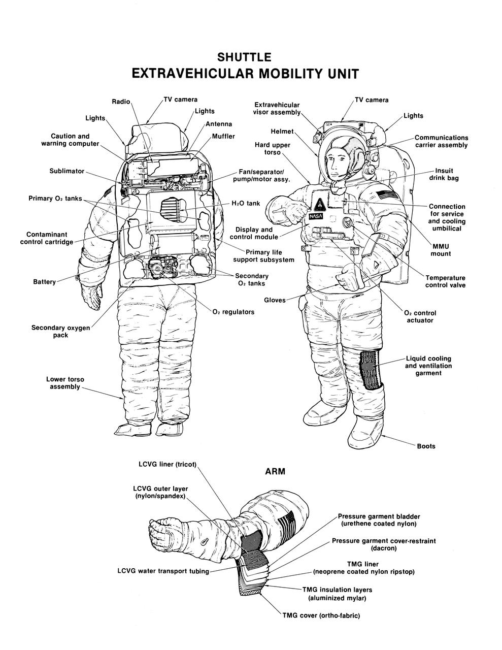
Labeled cutaway line drawing of the Shuttle extravehicular mobility unit (EMU) identifies its various components and equipment. The portable life support system (PLSS) and protective layers of fabric (thermal micrometeoroid garment (TMG)) incorporated in this extravehicular activity (EVA) space suit are shown.
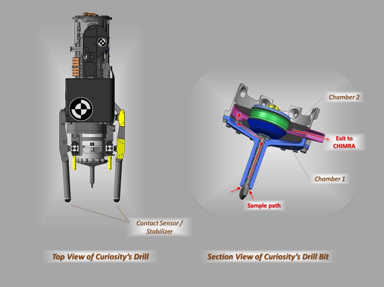
These schematic drawings show a top view and a cutaway view of a section of the drill on NASA Curiosity rover on Mars.
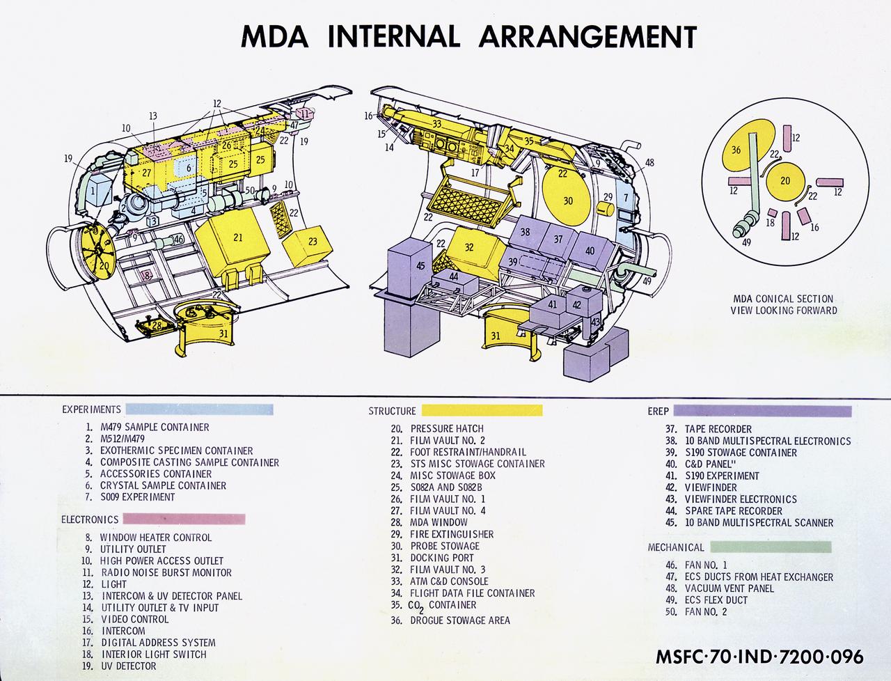
This cutaway drawing details the internal design of the Skylab Multiple Docking Adapter (MDA). The MDA, built under the direction of the Marshall Space Flight Center, housed various Skylab control and experiment units, and provided a docking port for the Apollo Command Module (CM).
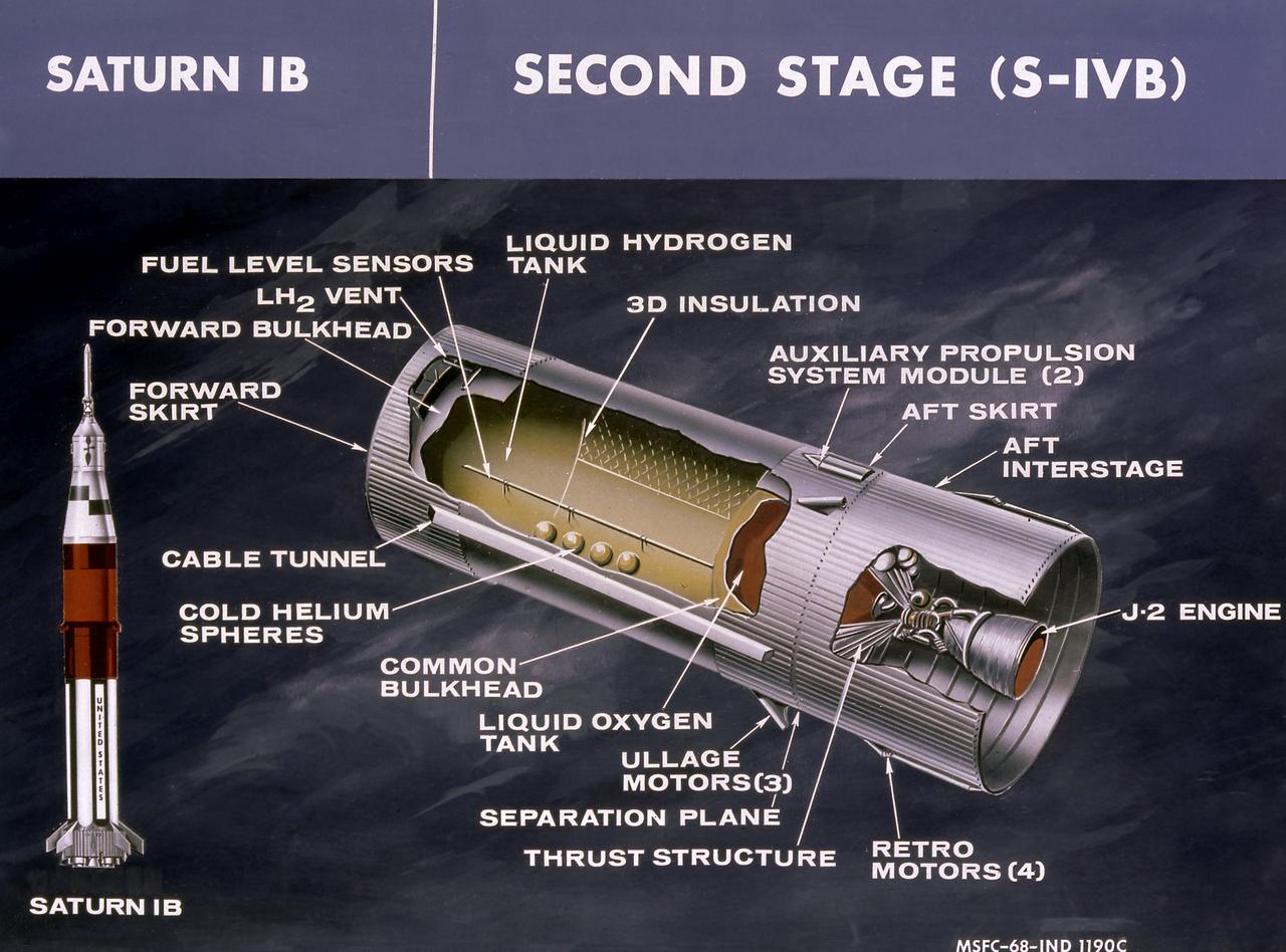
This cutaway drawing shows the S-IVB stage in its Saturn IB configuration. As a part of the Marshall Space Flight Center's (MSFC) "building block" approach to the Saturn development, the S-IVB stage was utilized in the Saturn IB launch vehicle as a second stage and, later, the Saturn V launch vehicle as a third stage. The stage was powered by a single J-2 engine, initially capable of 200,000 pounds of thrust.
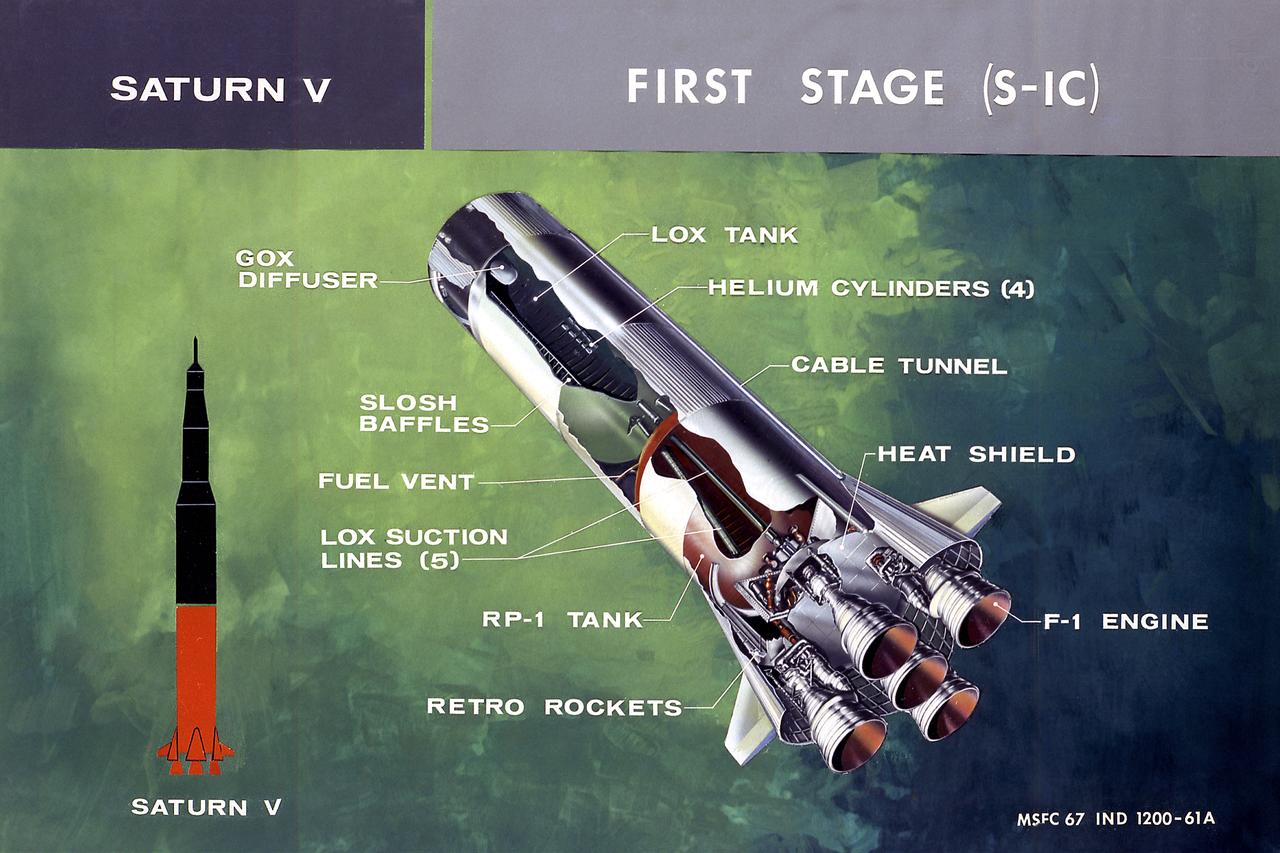
This illustration shows a cutaway drawing with callouts of the major components for the S-IC (first) stage of the Saturn V launch vehicle. The S-IC stage is 138 feet long and 33 feet in diameter, producing more than 7,500,000 pounds of thrust through five F-1 engines powered by liquid oxygen and kerosene. Four of the engines are mounted on an outer ring and gimball for control purposes. The fifth engine is rigidly mounted in the center. When ignited, the roar produced by the five engines equals the sound of 8,000,000 hi-fi sets.
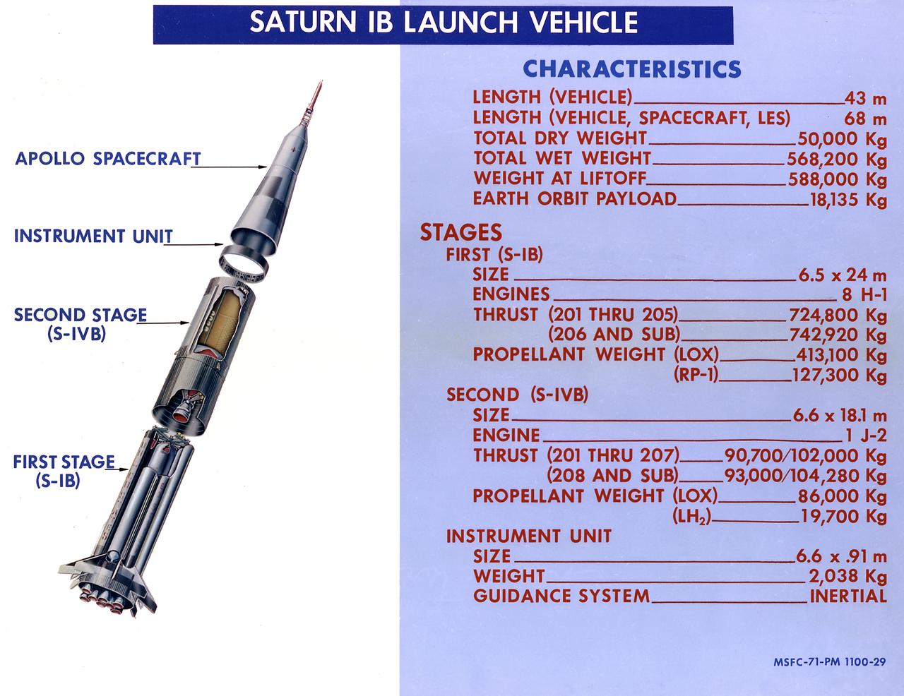
This 1968 cutaway drawing illustrates the Saturn IB launch vehicle with its two booster stages, the S-IB (first stage) and S-IVB (second stage), and provides the vital statistics in metric units. Developed by the Marshall Space Flight Center (MSFC) as an interim vehicle in MSFC's "building block" approach to the Saturn rocket development, the Saturn IB utilized Saturn I technology to further develop and refine the larger boosters and the Apollo spacecraft capabilities required for the marned lunar missions.
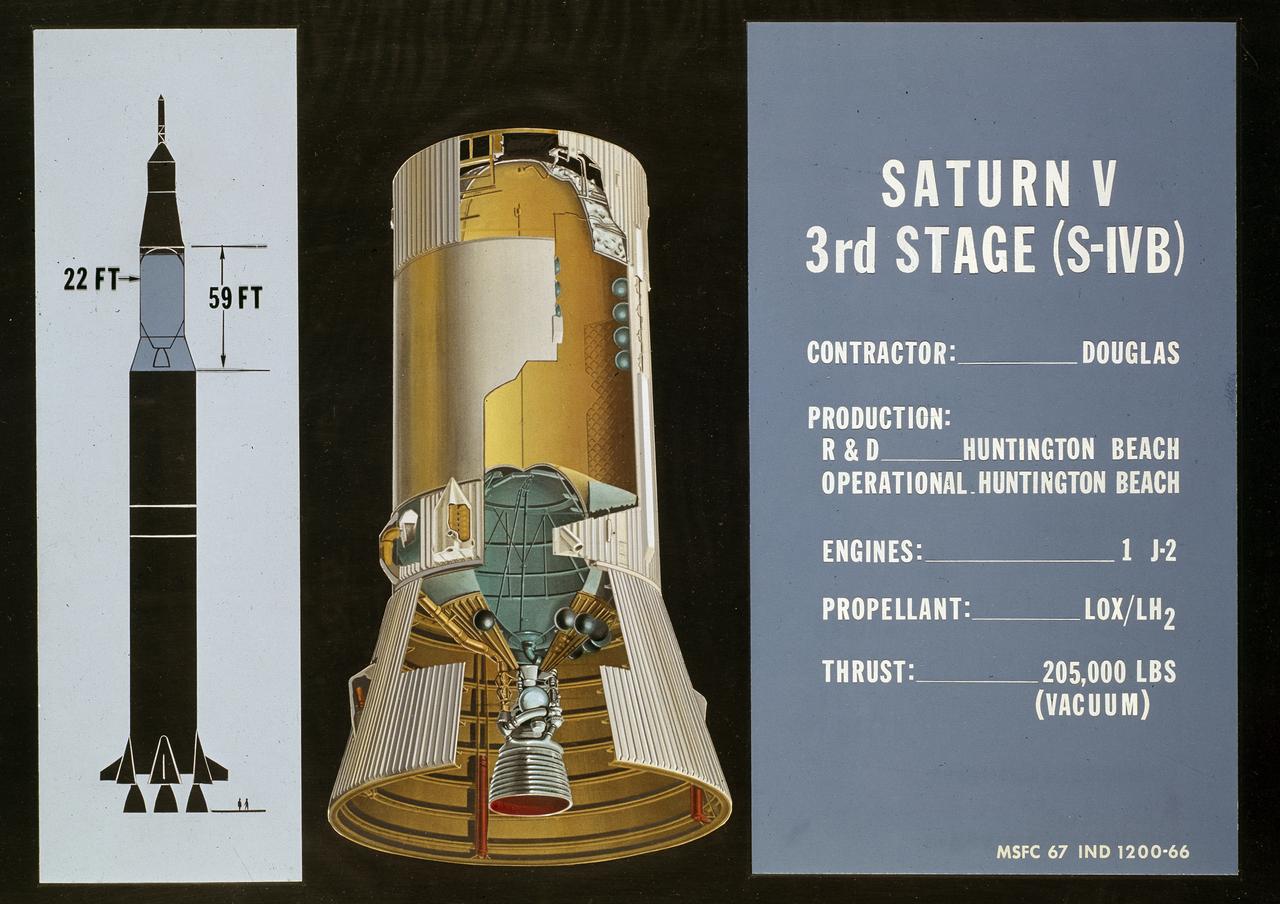
This cutaway drawing shows the S-IVB (third stage) of the Saturn V launch vehicle. As a part of the Marshall Space Flight Center’s (MSFC) “building block” approach to the Saturn development, the S-IVB stage was utilized in the Saturn IB launch vehicle as a second stage and, later, the Saturn V launch vehicle as a third stage. The 59 foot long and 22 feet diameter stage was powered by a single J-2 engine, initially capable of 200,000 pounds of thrust.
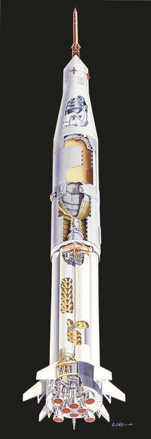
This undated cutaway drawing illustrates the Saturn IB launch vehicle with its two booster stages, the S-IB and S-IVB. Developed by the Marshall Space Flight Center (MSFC) as an interim vehicle in MSFC's "building block" approach to the Saturn rocket development, the Saturn IB utilized Saturn I technology to further develop and refine the larger boosters and the Apollo spacecraft capabilities required for the marned lunar missions.
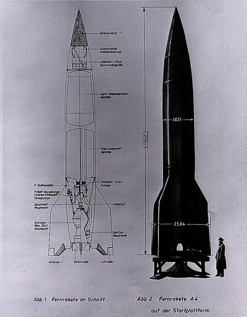
This German cutaway drawing of the Aggregate-4 (A-4) illustrates the dimensions and internal workings of the rocket. Later renamed the V-2, the rocket was developed by Dr. Wernher von Braun and the German Rocket Team at Peenemuende on the Baltic Sea. At the end of World War II, the team of German engineers and scientists came to the United States to work for the Army at Fort Bliss, Texas, and Redstone Arsenal in Huntsville, Alabama.
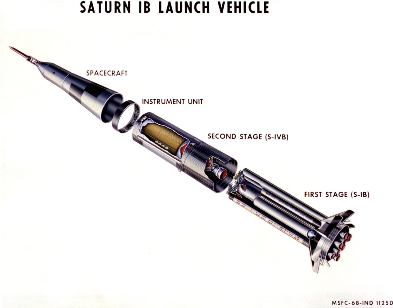
This 1968 cutaway drawing illustrates the Saturn IB launch vehicle with its two booster stages, the S-IB and S-IVB. Developed by the Marshall Space Flight Center (MSFC) as an interim vehicle in MSFC's "building block" approach to the Saturn rocket development, the Saturn IB utilized Saturn I technology to further develop and refine the larger boosters and the Apollo spacecraft capabilities required for the marned lunar mission.
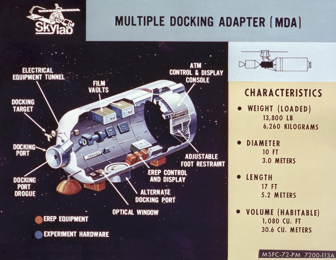
This cutaway drawing details the major characteristics of the Skylab Multiple Docking Adapter (MDA). The MDA, built under the direction of the Marshall Space Flight Center, housed the control units for the Apollo Telescope Mount (ATM), Earth Resources Experiment Package (EREP), and Zero-Gravity Materials Processing Facility, and provided a docking port for the Apollo Command Module (CM).
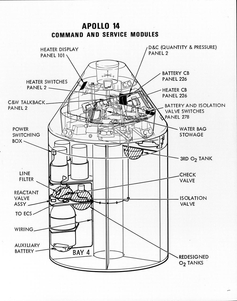
S71-16823 (January 1971) --- A line drawing illustrating a cutaway view of the Apollo 14 Command and Service Modules, showing the engineering changes in the CSM which were recommended by the Apollo 13 Review Board. (The Apollo 13 abort was caused by a short circuit and wiring overheating in one of the SM cryogenic oxygen tanks.) The major changes to the Apollo 14 CSM include adding a third cryogenic oxygen tank installed in a heretofore empty bay (in sector one) of the SM, addition of an auxiliary battery in the SM as a backup in case of fuel cell failure, and removal of destratification fans in the cryogenic oxygen tanks and removal of thermostat switches from the oxygen tank heater circuits. Provision for stowage of an emergency five-gallon supply of drinking water has been added to the CM.
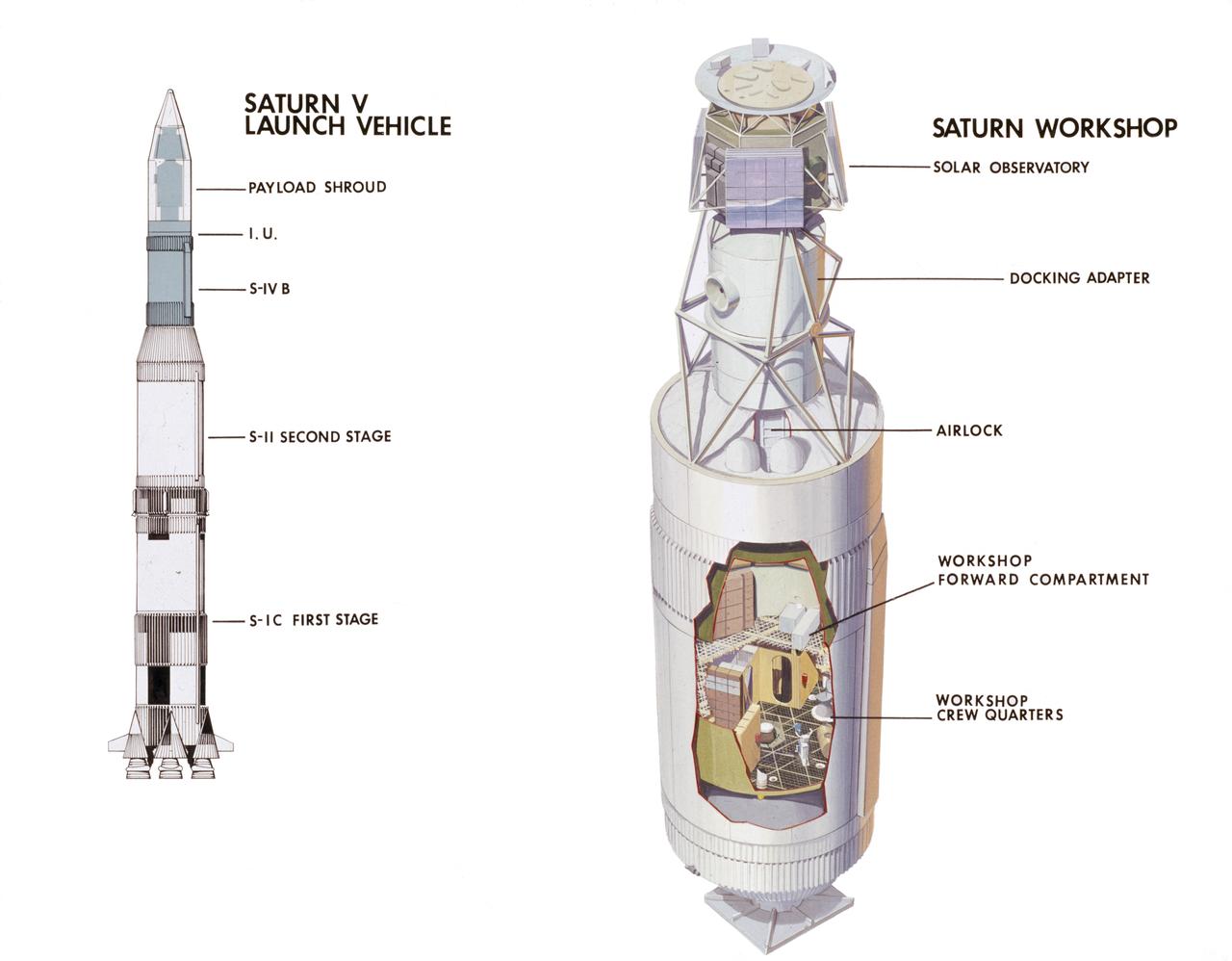
This cutaway drawing illustrates major Skylab components in launch configuration on top of the Saturn V. In an early effort to extend the use of Apollo for further applications, NASA established the Apollo Applications Program (AAP) in August of 1965. The AAP was to include long duration Earth orbital missions during which astronauts would carry out scientific, technological, and engineering experiments in space by utilizing modified Saturn launch vehicles and the Apollo spacecraft. Established in 1970, the Skylab Program was the forerurner of the AAP. The goals of the Skylab were to enrich our scientific knowledge of the Earth, the Sun, the stars, and cosmic space; to study the effects of weightlessness on living organisms, including man; to study the effects of the processing and manufacturing of materials utilizing the absence of gravity; and to conduct Earth resource observations. The Skylab also conducted 19 selected experiments submitted by high school students. Skylab's 3 different 3-man crews spent up to 84 days in Earth orbit. The Marshall Space Flight Center (MSFC) had responsibility for developing and integrating most of the major components of the Skylab: the Orbital Workshop (OWS), Airlock Module (AM), Multiple Docking Adapter (MDA), Apollo Telescope Mount (ATM), Payload Shroud (PS), and most of the experiments. MSFC was also responsible for providing the Saturn IB launch vehicles for three Apollo spacecraft and crews and a Saturn V launch vehicle for the Skylab.