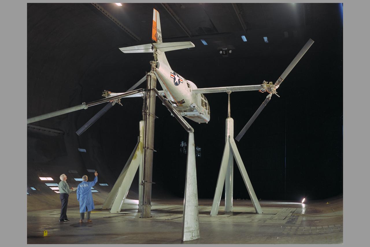
XV-3 in Ames Reseach Center 40x80ft wind tunnel; Rotor dynamic stability tests
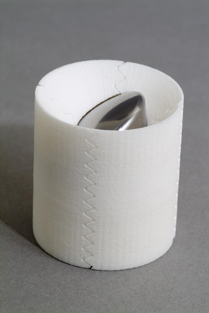
CEV (Crew Escape Vehicle) capsule Balistic Range testing to examine static and dynamic stability characteristics (at the Hypervelocity Free-Flight Facility) HFF
CEV (Crew Escape Vehicle) capsule Balistic Range testing to examine static and dynamic stability characteristics (at the Hypervelocity Free-Flight Facility) HFF
CEV (Crew Escape Vehicle) capsule Balistic Range testing to examine static and dynamic stability characteristics (at the Hypervelocity Free-Flight Facility) HFF
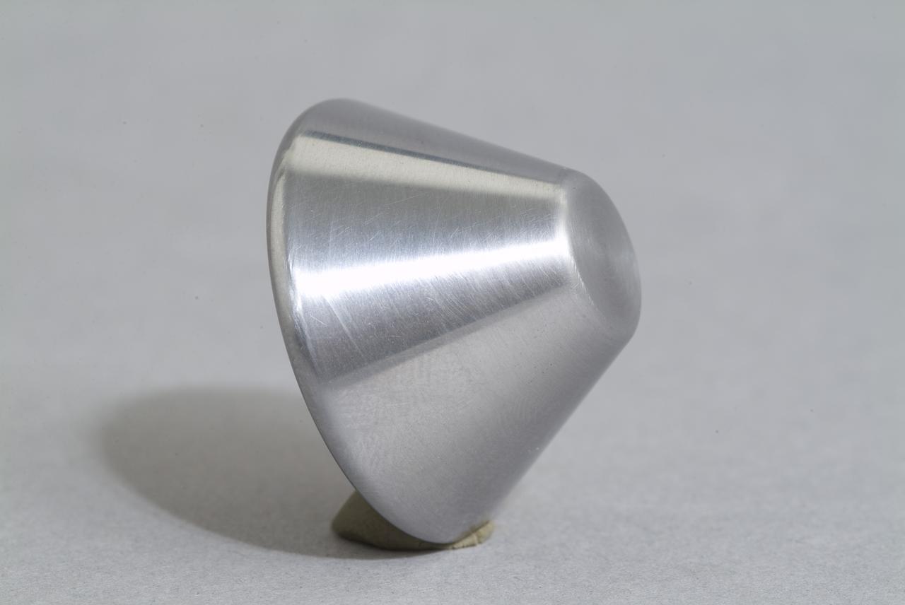
CEV (Crew Escape Vehicle) capsule Balistic Range testing to examine static and dynamic stability characteristics (at the Hypervelocity Free-Flight Facility) HFF
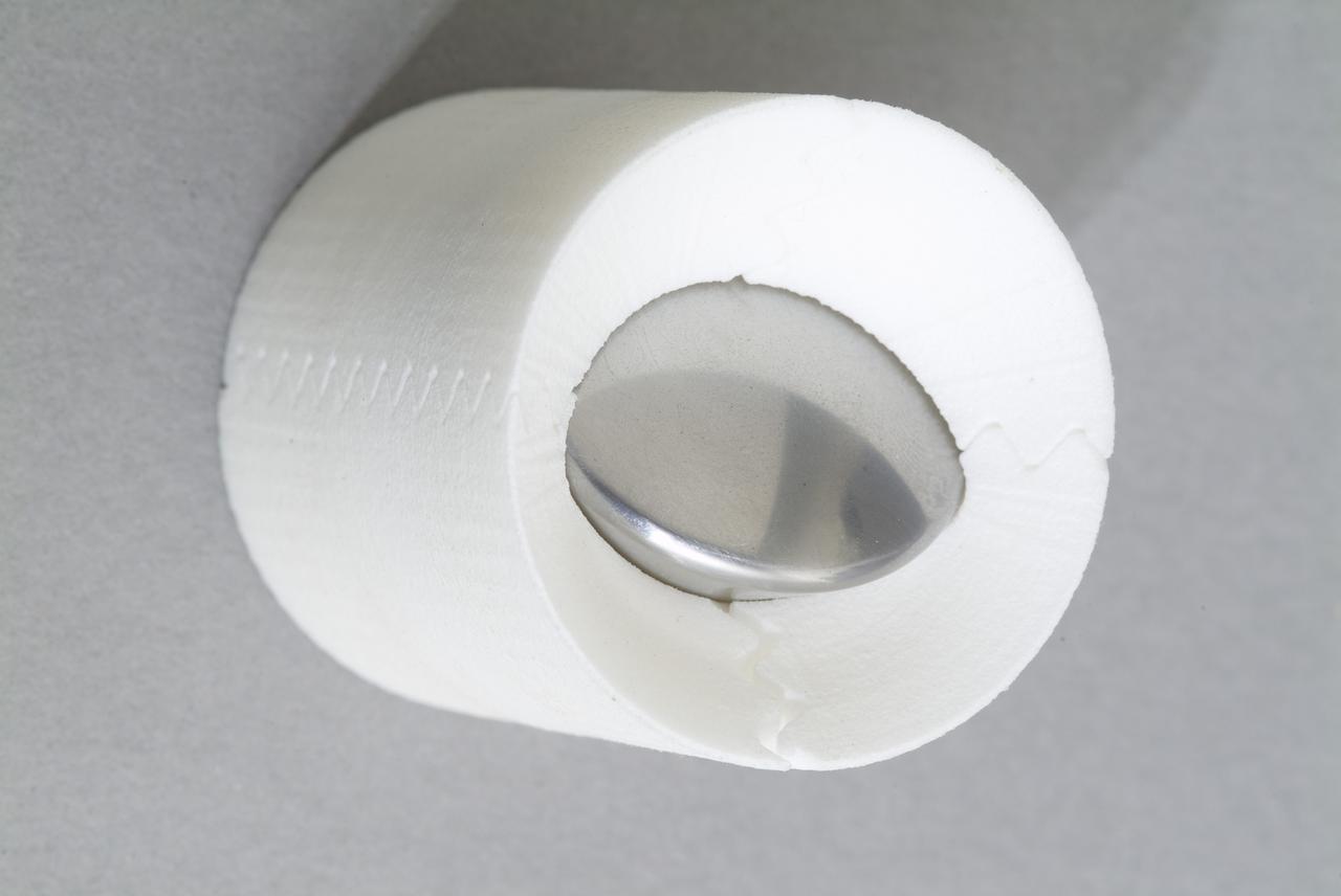
CEV (Crew Escape Vehicle) capsule Balistic Range testing to examine static and dynamic stability characteristics (at the Hypervelocity Free-Flight Facility) HFF
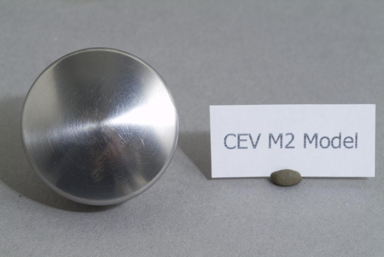
CEV (Crew Escape Vehicle) capsule Balistic Range testing to examine static and dynamic stability characteristics (at the Hypervelocity Free-Flight Facility) HFF
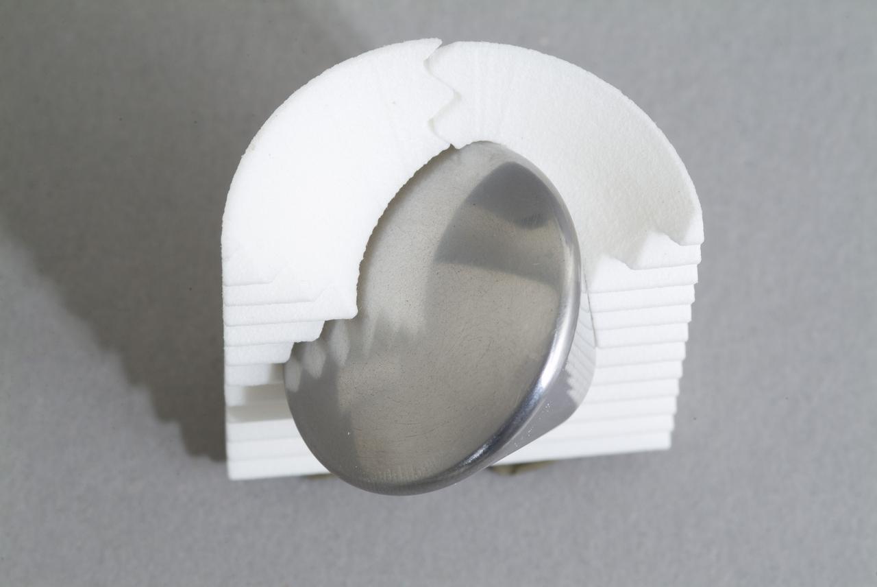
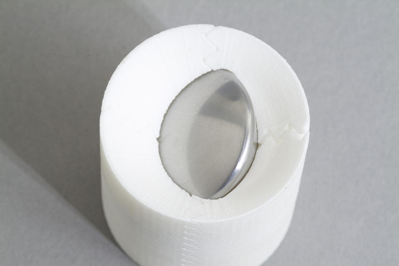
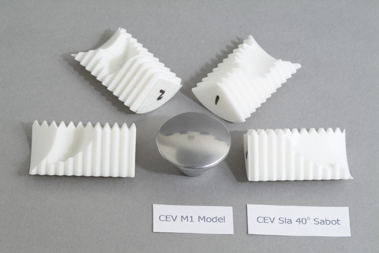
CEV (Crew Escape Vehicle) capsule Balistic Range testing to examine static and dynamic stability characteristics (at the Hypervelocity Free-Flight Facility) HFF - model M-1 in 40 degree initial launch angle with sabot
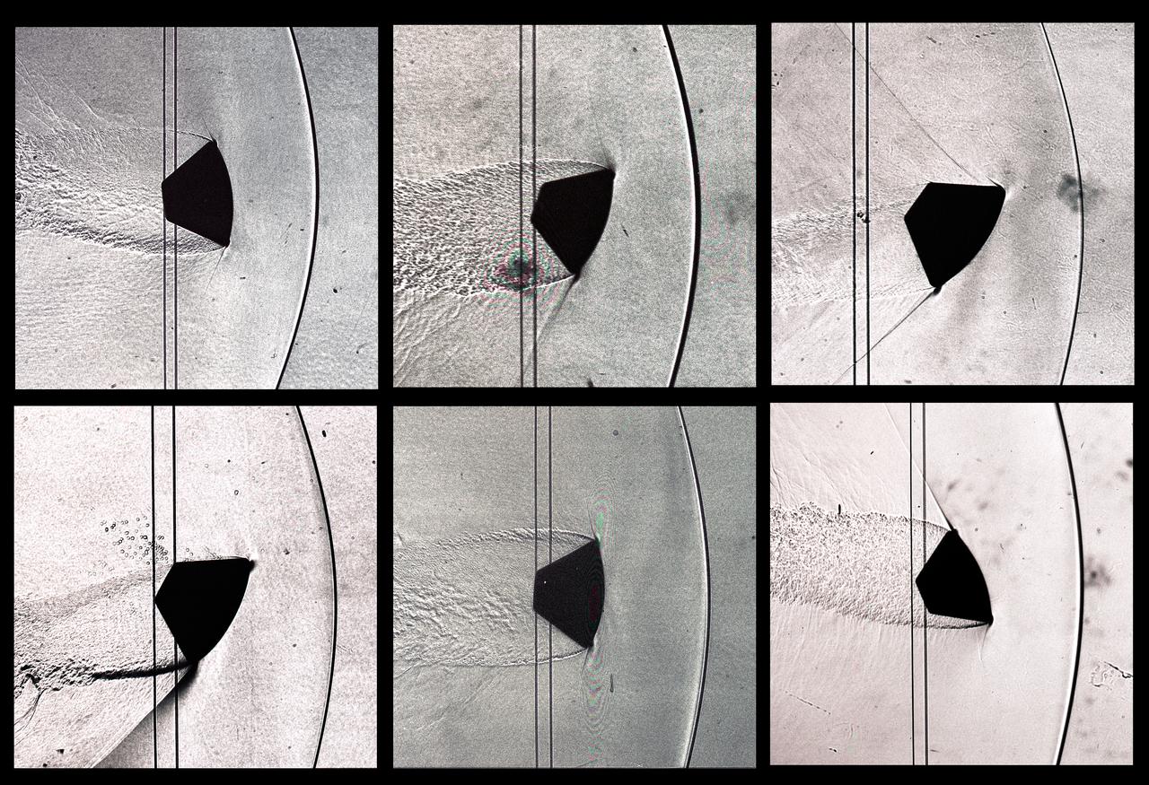
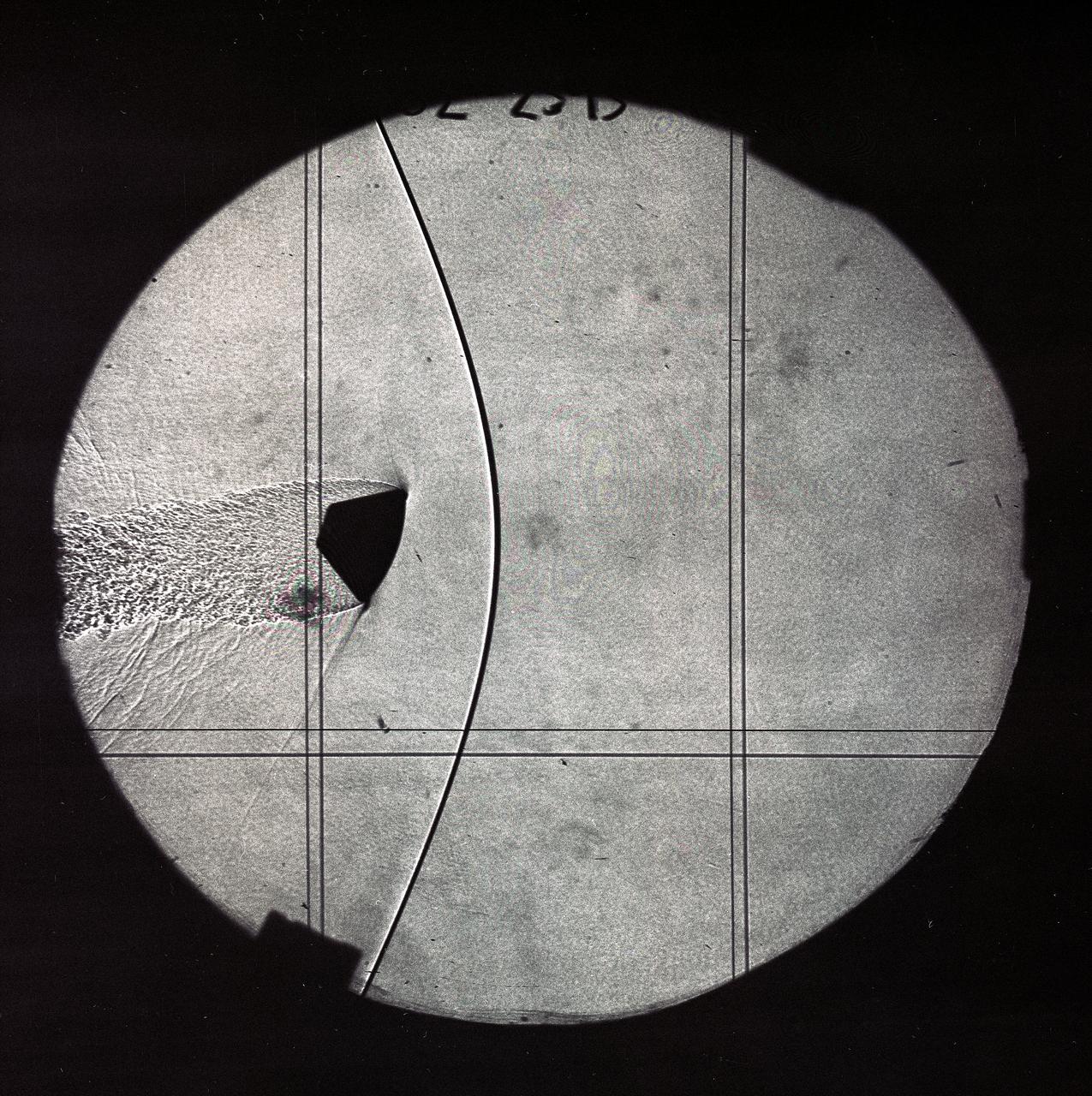
CEV (Crew Escape Vehicle) capsule Balistic Range testing to examine static and dynamic stability characteristics (at the Hypervelocity Free-Flight Facility) HFF - scans of shadowgraphs from 8x10 film images
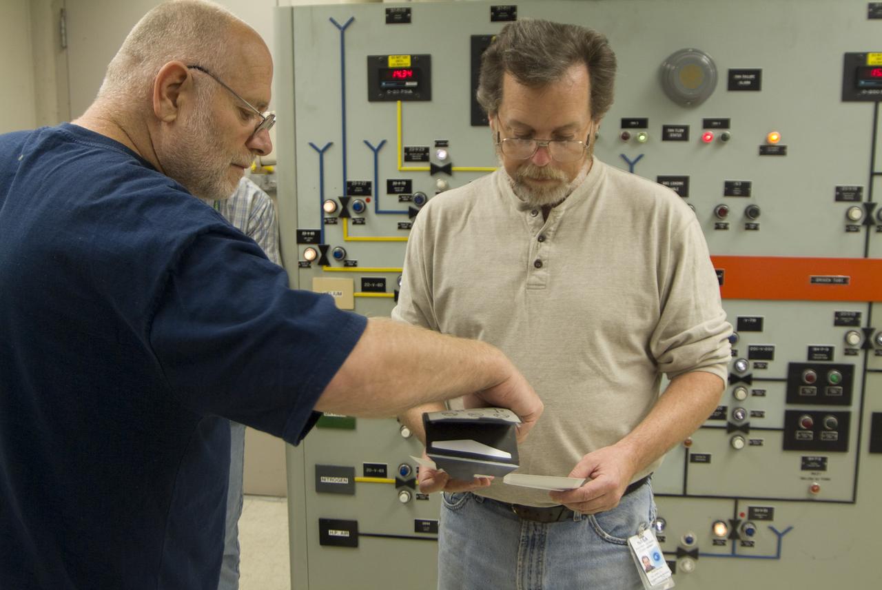
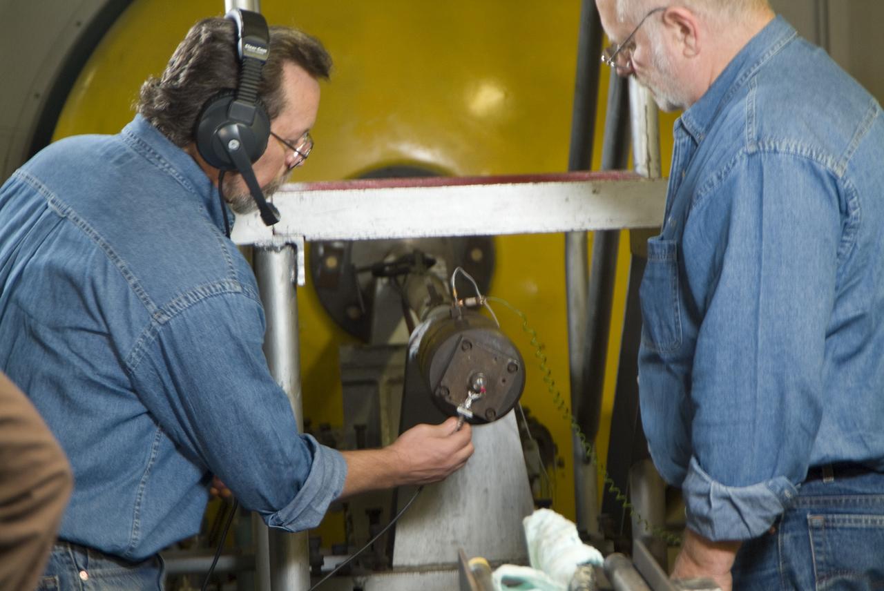
CEV (Crew Escape Vehicle) capsule Balistic Range testing to examine static and dynamic stability characteristics (at the Hypervelocity Free-Flight Facility) HFF - Don Holt (L) & Don Bowling (r) in control room examining poloroids

CEV (Crew Escape Vehicle) capsule Balistic Range testing to examine static and dynamic stability characteristics (at the Hypervelocity Free-Flight Facility) HFF - Bon Bowling machining sabot to find dimensions
CEV (Crew Escape Vehicle) capsule Balistic Range testing to examine static and dynamic stability characteristics (at the Hypervelocity Free-Flight Facility) HFF - scans of shadowgraphs from 8x10 film images
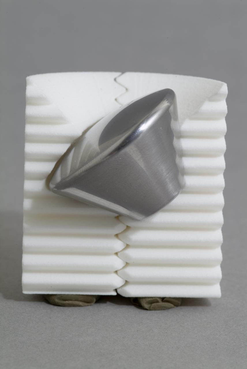
CEV (Crew Escape Vehicle) capsule Balistic Range testing to examine static and dynamic stability characteristics (at the Hypervelocity Free-Flight Facility) HFF - model M-1 in 40 degree initial launch angle with sabot
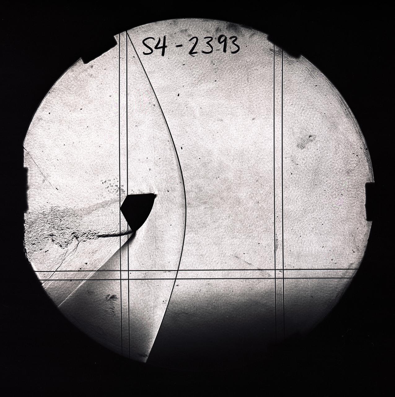
CEV (Crew Escape Vehicle) capsule Balistic Range testing to examine static and dynamic stability characteristics (at the Hypervelocity Free-Flight Facility) HFF - scans of shadowgraphs from 8x10 film images
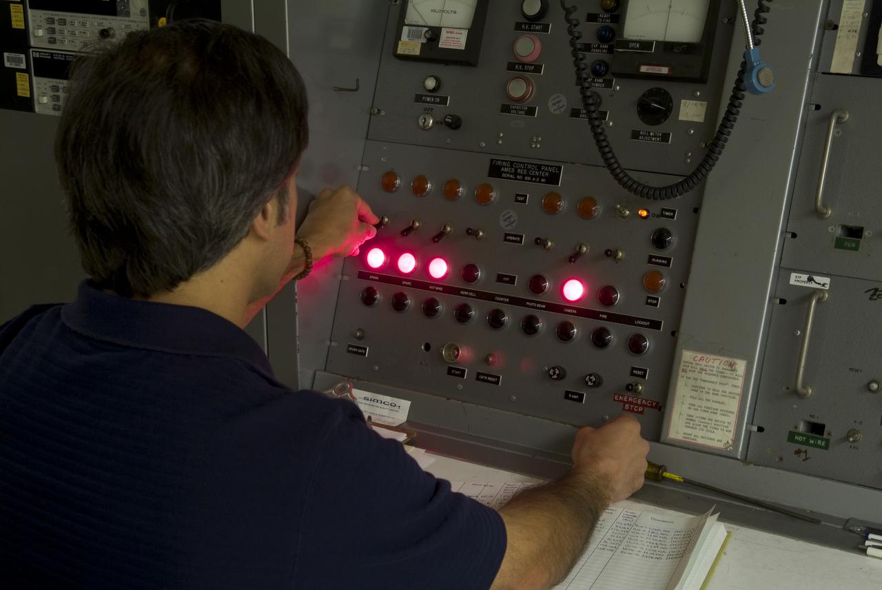
CEV (Crew Escape Vehicle) capsule Balistic Range testing to examine static and dynamic stability characteristics (at the Hypervelocity Free-Flight Facility) HFF Chuck Cornelison operating 'Firing' control pannel

CEV (Crew Escape Vehicle) capsule Balistic Range testing to examine static and dynamic stability characteristics (at the Hypervelocity Free-Flight Facility) HFF - scans of shadowgraphs from 8x10 film images
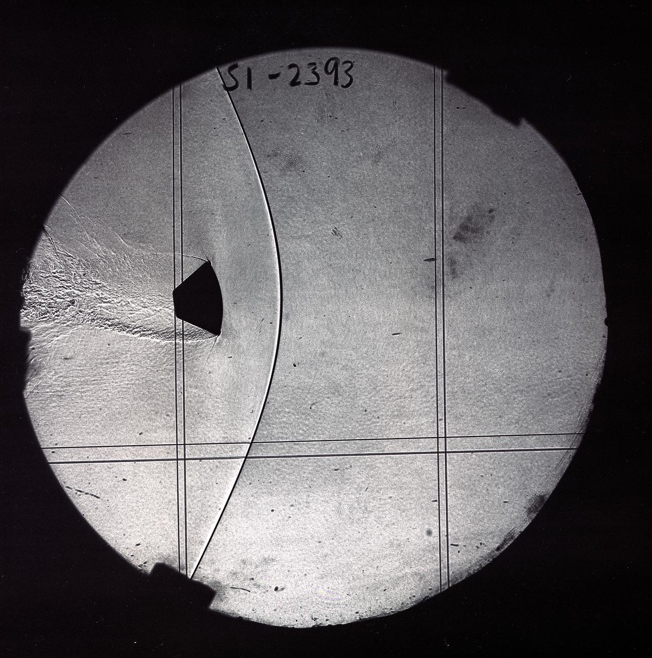
CEV (Crew Escape Vehicle) capsule Balistic Range testing to examine static and dynamic stability characteristics (at the Hypervelocity Free-Flight Facility) HFF - scans of shadowgraphs from 8x10 film images
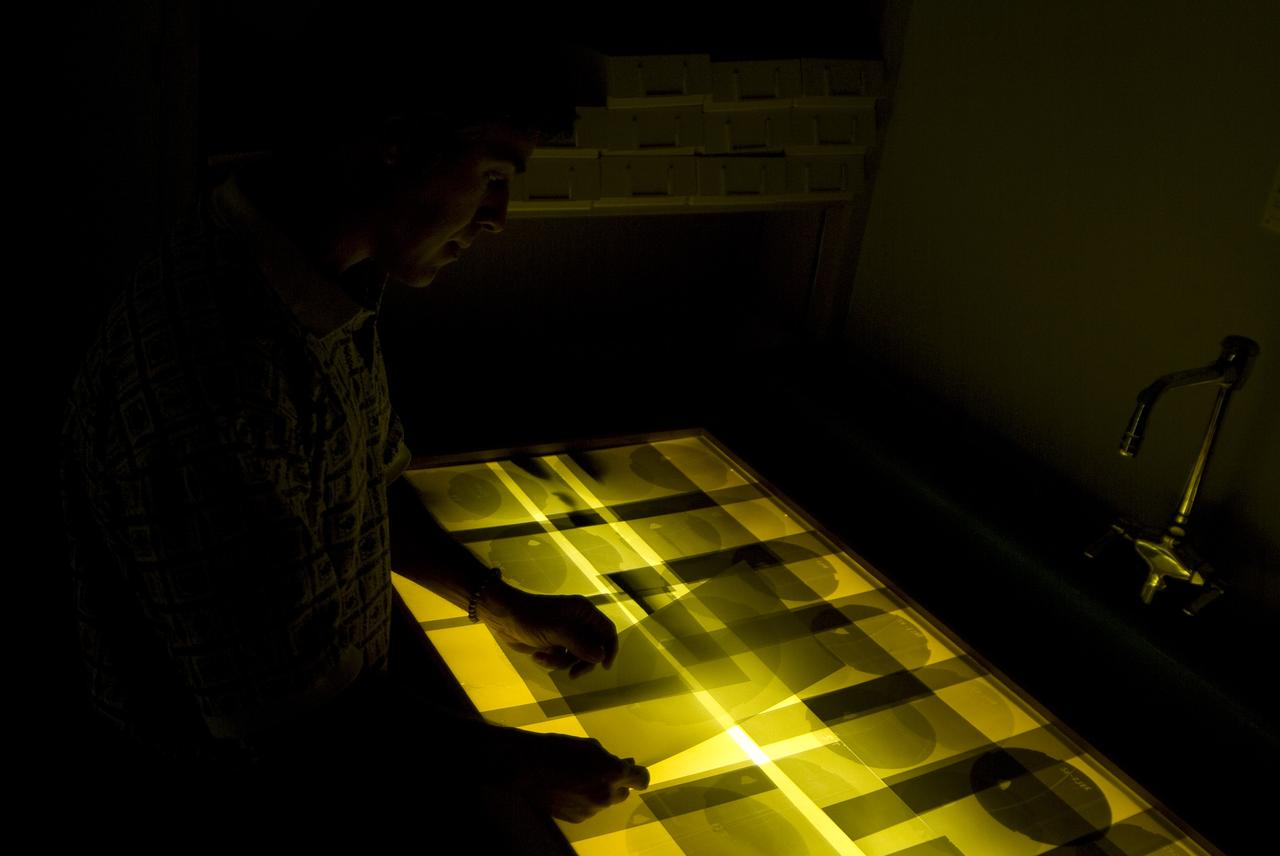
CEV (Crew Escape Vehicle) capsule Balistic Range testing to examine static and dynamic stability characteristics (at the Hypervelocity Free-Flight Facility) HFF - Chuck Cornelison viewing 8x10 shadowgraph images
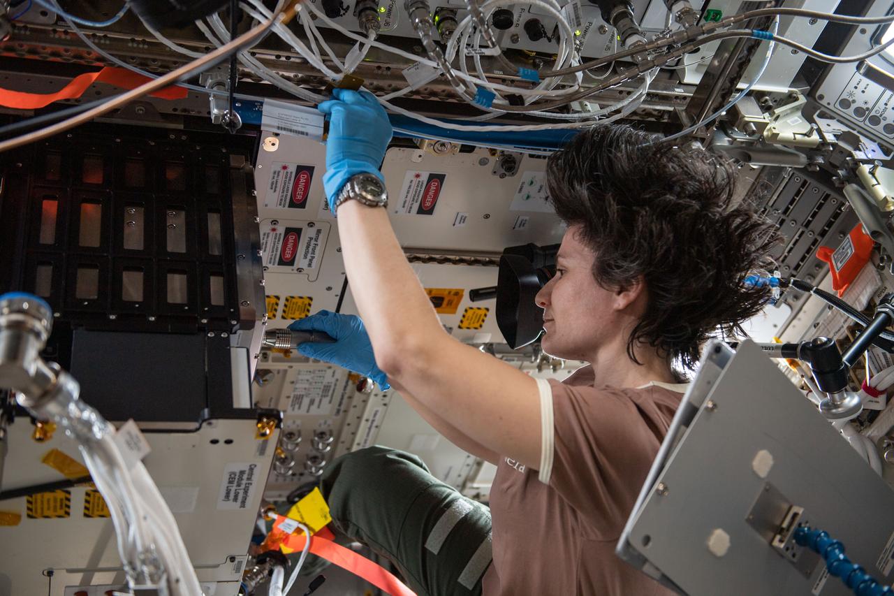
iss067e253409 (Aug. 10, 2022) --- ESA (European Space Agency) astronaut Samantha Cristoforetti works on ESA’s FSL Soft Matter Dynamics - PASTA, a study of whether additives increase or decrease the stability of emulsions. These phenomena can be better observed in microgravity, where the effects of buoyancy are absent.
CEV (Crew Escape Vehicle) capsule Balistic Range testing to examine static and dynamic stability characteristics (at the Hypervelocity Free-Flight Facility) HFF - Don Bowling (l) attaching firing cable to breeth cap as Don Holt (r) looks on

DURING APPROACH. OGEE Wing Planform on modified F5D-1 SkylancerAirplane Flight Tests. 'Flow Visualization Photographs'. In landing approach trials at Moffett Field, vapor trails are generated by low pressure in votex flow near wing leading edge on upper wing surface. Studies were undertaken in efforts to determine if there were adverse effects of vortex flow on the dynamic stability of the aircraft.
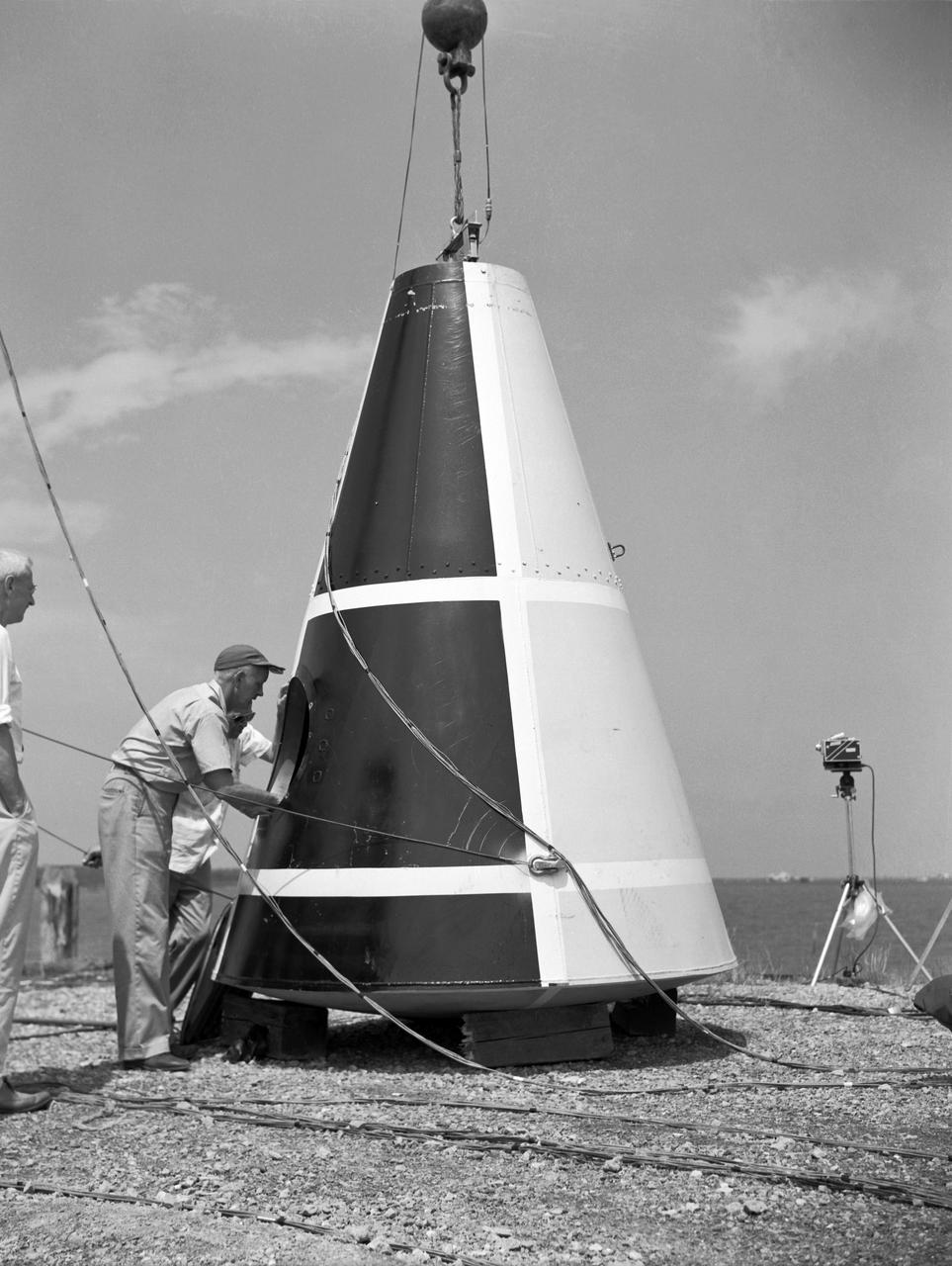
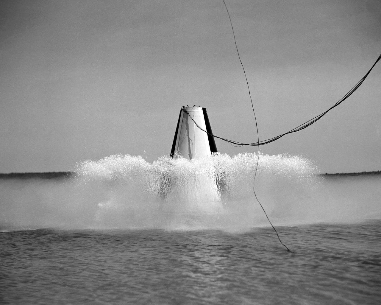
Photographed on: 08 05 1958. -- Impact test conducted by Langley's Hydrodynamics Division. The Division conducted a series of impact studies with full scale and model capsules of the original capsule shape A. Joseph Shortal wrote (Vol. 3, p. 16): The basic design of the capsule was made by M.A. Faget and his coworkers at PARD during the winter of 1957-1958. It was natural, then, that extensive use was made of the facilities at Wallops during the development of the spacecraft. The tests at Wallops consisted of 26 full-size capsules, either launched from the ground by rocket power or dropped from airplanes at high altitude and 28 scaled models, either rocket boosted or released from balloons. Emphasis in the Wallops program was on dynamic stability and aerodynamic heating of the capsule, and effectiveness of the pilot-escape and parachute-recovery systems. The biggest part of the Wallops program was the series of full-size capsules, rocket launched with the Little Joe booster, developed especially for Mercury. -- Published in Joseph A. Shortal, History of Wallops Station: Origins and Activities Through 1949, (Wallops Island, VA: National Aeronautics and Space Administration, Wallops Station, nd), Comment Edition.
Photographed on: 08 05 1958. -- Impact test conducted by Langley's Hydrodynamics Division. The Division conducted a series of impact studies with full scale and model capsules of the original capsule shape A. Joseph Shortal wrote (Vol. 3, p. 16): The basic design of the capsule was made by M.A. Faget and his coworkers at PARD during the winter of 1957-1958. It was natural, then, that extensive use was made of the facilities at Wallops during the development of the spacecraft. The tests at Wallops consisted of 26 full-size capsules, either launched from the ground by rocket power or dropped from airplanes at high altitude and 28 scaled models, either rocket boosted or released from balloons. Emphasis in the Wallops program was on dynamic stability and aerodynamic heating of the capsule, and effectiveness of the pilot-escape and parachute-recovery systems. The biggest part of the Wallops program was the series of full-size capsules, rocket launched with the Little Joe booster, developed especially for Mercury. -- Published in Joseph A. Shortal, History of Wallops Station: Origins and Activities Through 1949, (Wallops Island, VA: National Aeronautics and Space Administration, Wallops Station, nd), Comment Edition.
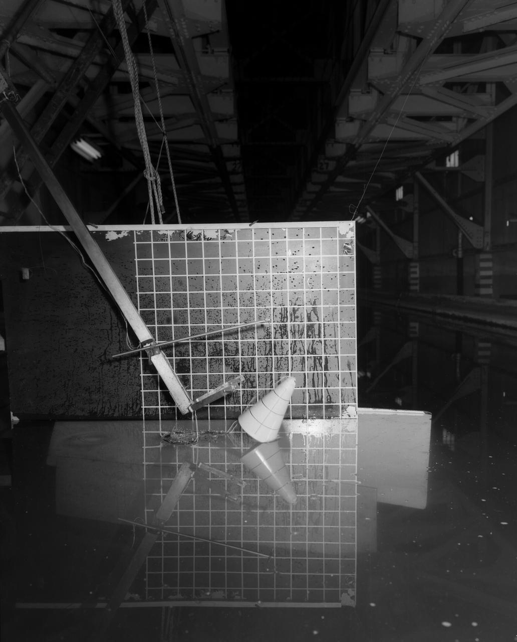
Testing of Mercury Capsule Shape A by the Hydrodynamics Division of Langley. Joseph Shortal wrote (vol. 3, p. 19): The Hydrodynamics Division provided assistance in determining landing loads. In this connection, after PARD engineers had unofficially approached that division to make some water impact tests with the boilerplate capsule, J.B. Parkinson, Hydrodynamics Chief visited Shortal to find out if the request had his support. Finding out that it did, Parkinson said, Its your capsule. If you want us to drop it in the water, we will do it. From Shortal (Vol. 3, p. 16): The basic design of the capsule was made by M.A. Faget and his coworkers at PARD during the winter of 1957-1958. It was natural, then, that extensive use was made of the facilities at Wallops during the development of the spacecraft. The tests at Wallops consisted of 26 full-size capsules, either launched from the ground by rocket power or dropped from airplanes at high altitude and 28 scaled models, either rocket boosted or released from balloons. Emphasis in the Wallops program was on dynamic stability and aerodynamic heating of the capsule, and effectiveness of the pilot-escape and parachute-recovery systems. The biggest part of the Wallops program was the series of full-size capsules, rocket launched with the Little Joe booster, developed especially for Mercury. -- Published in Joseph A. Shortal, History of Wallops Station: Origins and Activities Through 1949, (Wallops Island, VA: National Aeronautics and Space Administration, Wallops Station, nd), Comment Edition.
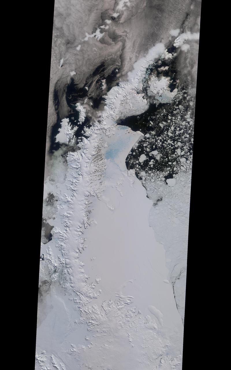
A rift in Antarctica's Larsen C ice shelf has grown to 110 miles (175 km) long, making it inevitable that an iceberg larger than Rhode Island will soon calve from the ice shelf. Larsen C is the fourth largest ice shelf in Antarctica, with an area of almost 20,000 square miles (50,000 square kilometers). The calving event will remove approximately 10 percent of the ice shelf's mass, according to the Project for Impact of Melt on Ice Shelf Dynamics and Stability (MIDAS), a UK-based team studying the ice shelf. Only 12 miles (20 km) of ice now separates the end of the rift from the ocean. The rift has grown at least 30 miles (50 km) in length since August, but appears to be slowing recently as Antarctica returns to polar winter. Project MIDAS reports that the calving event might destabilize the ice shelf, which could result in a collapse similar to what occurred to the Larsen B ice shelf in 2002. The Multi-angle Imaging SpectroRadiometer (MISR) instrument aboard NASA's Terra satellite captured views of Larsen C on August 22, 2016, when the rift was 80 miles (130 km) in length; December 8, 2016, when the rift was approximately 90 miles (145 km) long; and April 6, 2017. The MISR instrument has nine cameras, which view the Earth at different angles. The overview image, from December 8, shows the entire Antarctic Peninsula -- home to Larsen A, B, and C ice shelves -- in natural color (similar to how it would appear to the human eye) from MISR's vertical-viewing camera. Combining information from several MISR cameras pointed at different angles gives information about the texture of the ice. The accompanying GIF depicts the inset area shown on the larger image and displays data from all three dates in false color. These multiangular views -- composited from MISR's 46-degree backward-pointing camera, the nadir (vertical-viewing) camera, and the 46-degree forward-pointing camera -- represent variations in ice texture as changes in color, such that areas of rough ice appear orange and smooth ice appears blue. The Larsen C shelf is on the left in the GIF, bordered by the Weddell Sea on the upper right. The ice within the rift is orange, indicating movement, and the end of the rift can be tracked across the shelf between images. In addition, between December and April, the rift widened, pushing the future iceberg away from the shelf at its southern end. These data were acquired during Terra orbits 88717, 90290 and 92023. https://photojournal.jpl.nasa.gov/catalog/PIA21581

In this illustration showing NEO Surveyor, NASA's next-generation near-Earth object hunter, the spacecraft floats in an infrared starfield containing stars, star clusters, gas, and dust. More than 100 asteroids can be seen as red dots, with some of them visible in a track that shows how they were captured at different times as they marched across the sky. This starfield was observed by NASA's Wide-field Infrared Survey Explorer, or WISE, during its primary all-sky survey in March 2010 before it was put into hibernation a year later. In December 2013, the space telescope was reactivated to search for more asteroids as the NEOWISE mission. NASA's NEO Surveyor will build upon the successes of NEOWISE as the first space mission built specifically to find large numbers of hazardous asteroids and comets. The space telescope will launch to a region of gravitational stability between the Earth and the Sun called the L1 Lagrange point, where the spacecraft will orbit during its five-year primary mission. From this location, the space telescope will view the solar system in infrared wavelengths &ndash light that is invisible to the human eye. Because those wavelengths are mostly blocked by Earth's atmosphere, larger ground-based observatories may miss near-Earth objects that NEO Surveyor will be able to spot from space by using its modest light-collecting aperture of nearly 20 inches (50 centimeters). NEO Surveyor's cutting-edge detectors are designed to observe two heat-sensitive infrared bands that were chosen specifically so the spacecraft can track the most challenging-to-find near-Earth objects, such as dark asteroids and comets that don't reflect much visible light. In the infrared wavelengths to which NEO Surveyor is sensitive, these objects glow as they are heated by sunlight. In addition, NEO Surveyor will be able to find asteroids that approach Earth from the direction of the Sun, as well as those that lead and trail our planet's orbit, where they are typically obscured by the glare of sunlight – objects known as Earth Trojans. The mission is tasked by NASA's Planetary Science Division within the Science Mission Directorate; program oversight is provided by the PDCO, which was established in 2016 to manage the agency's ongoing efforts in planetary defense. NASA's Planetary Missions Program Office at Marshall Space Flight Center provides program management for NEO Surveyor. The project is being developed by JPL and is led by survey director Amy Mainzer at the University of Arizona. Established aerospace and engineering companies have been contracted to build the spacecraft and its instrumentation, including Ball Aerospace , Space Dynamics Laboratory, and Teledyne. The Laboratory for Atmospheric and Space Physics at the University of Colorado, Boulder will support operations, and IPAC-Caltech in Pasadena, California, is responsible for processing survey data and producing the mission's data products. Caltech manages JPL for NASA. https://photojournal.jpl.nasa.gov/catalog/PIA25253
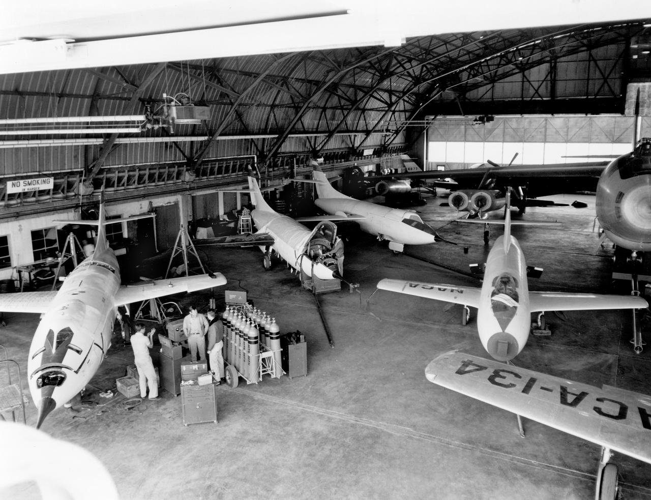
The aircraft in this 1953 photo of the National Advisory Committee for Aeronautics (NACA) hangar at South Base of Edwards Air Force Base showed the wide range of research activities being undertaken. On the left side of the hangar are the three D-558-2 research aircraft. These were designed to test swept wings at supersonic speeds approaching Mach 2. The front D-558-2 is the third built (NACA 145/Navy 37975). It has been modified with a leading-edge chord extension. This was one of a number of wing modifications, using different configurations of slats and/or wing fences, to ease the airplane's tendency to pitch-up. NACA 145 had both a jet and a rocket engine. The middle aircraft is NACA 144 (Navy 37974), the second built. It was all-rocket powered, and Scott Crossfield made the first Mach 2 flight in this aircraft on November 20, 1953. The aircraft in the back is D-558-2 number 1. NACA 143 (Navy 37973) was also carried both a jet and a rocket engine in 1953. It had been used for the Douglas contractor flights, then was turned over to the NACA. The aircraft was not converted to all-rocket power until June 1954. It made only a single NACA flight before NACA's D-558-2 program ended in 1956. Beside the three D-558-2s is the third D-558-1. Unlike the supersonic D-558-2s, it was designed for flight research at transonic speeds, up to Mach 1. The D-558-1 was jet-powered, and took off from the ground. The D-558-1's handling was poor as it approached Mach 1. Given the designation NACA 142 (Navy 37972), it made a total of 78 research flights, with the last in June 1953. In the back of the hangar is the X-4 (Air Force 46-677). This was a Northrop-built research aircraft which tested a swept wing design without horizontal stabilizers. The aircraft proved unstable in flight at speeds above Mach 0.88. The aircraft showed combined pitching, rolling, and yawing motions, and the design was considered unsuitable. The aircraft, the second X-4 built, was then used as a pilot traine