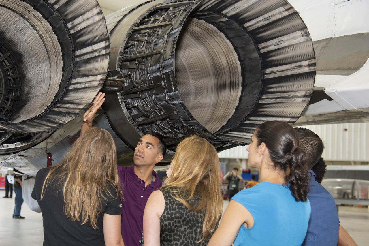
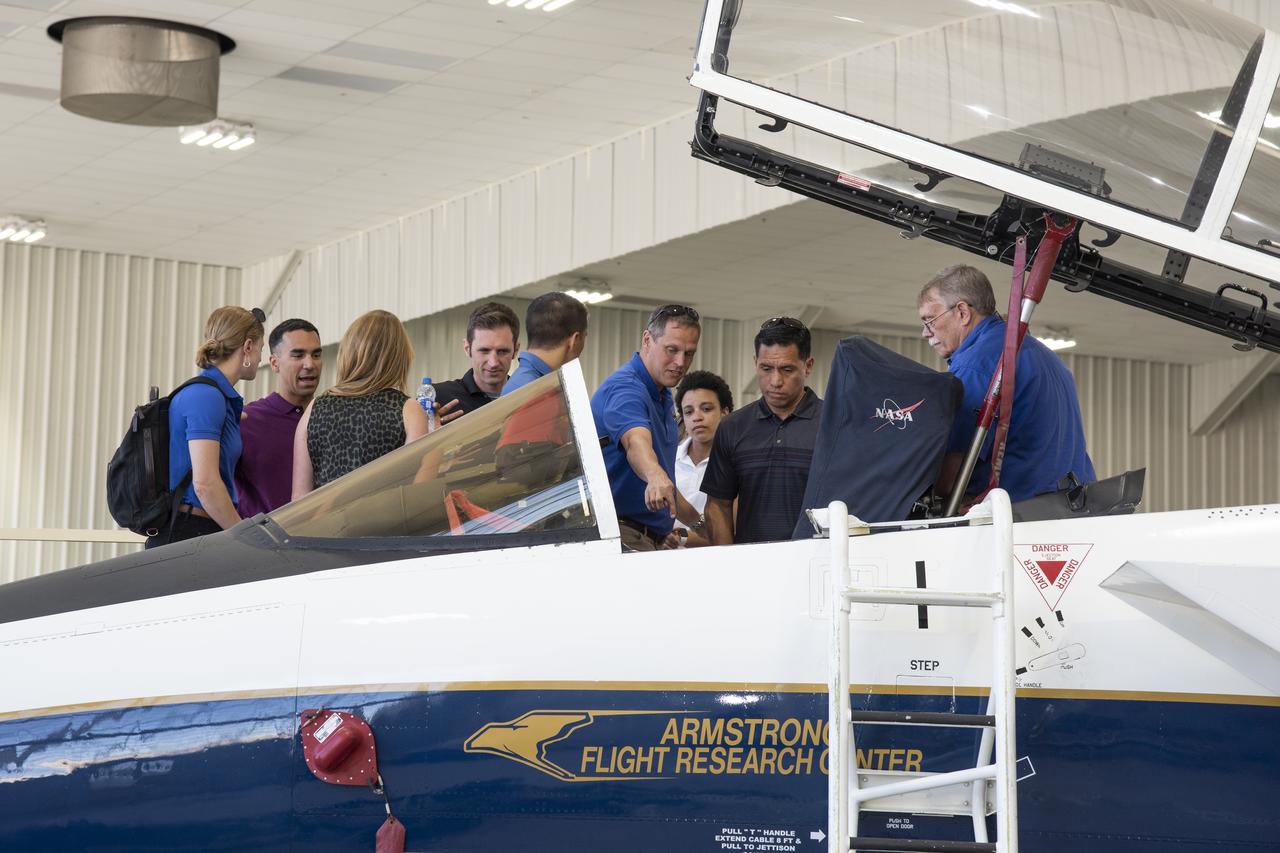
NASA's 2017 astronaut candidates toured aircraft hangar at Armstrong Flight Research Center, in Southern California (L to R) Jenni Sidey-Gibbons, Raja Chari, Loral O'Hara, Jasmin Moghbeli, Jonny Kim and Jessica Watkins look inside the engine nozzle of an F-15 jet. The F-15 will fly in tandem with the X-59 QueSST during early flight test stages for the X-59 development.
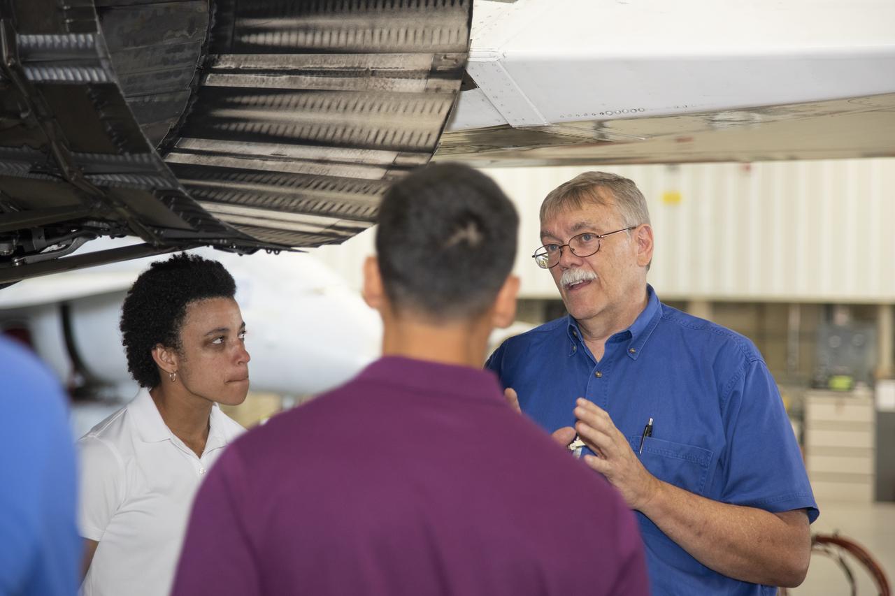
NASA's 2017 astronaut candidates toured aircraft hangar at Armstrong Flight Research Center, in Southern California where Crew Chief Tom Grindle talks with (L to R) Jessica Watkins and Raja Chari near engine nozzle of F-15 jet. The F-15 will fly in tandem with the X-59 QueSST during early flight test stages for the X-59 development.
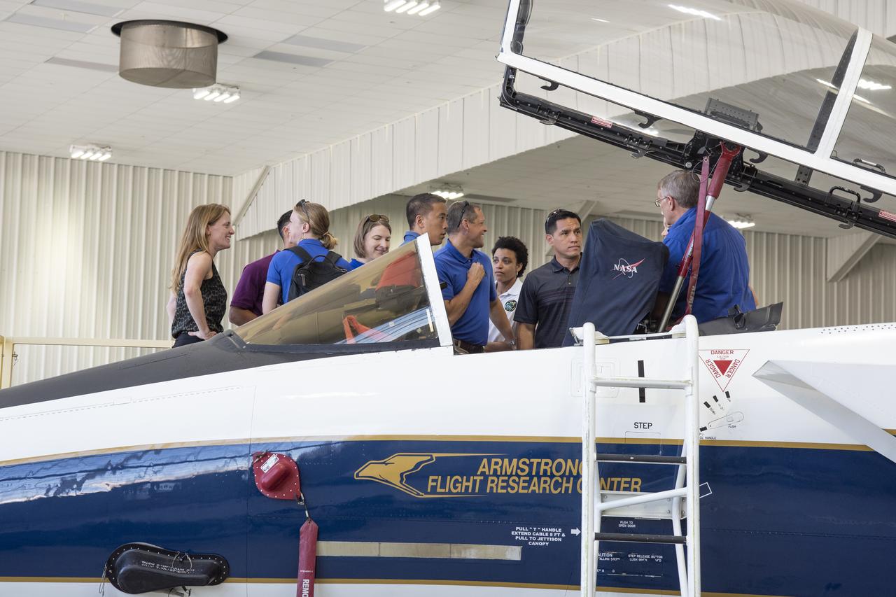
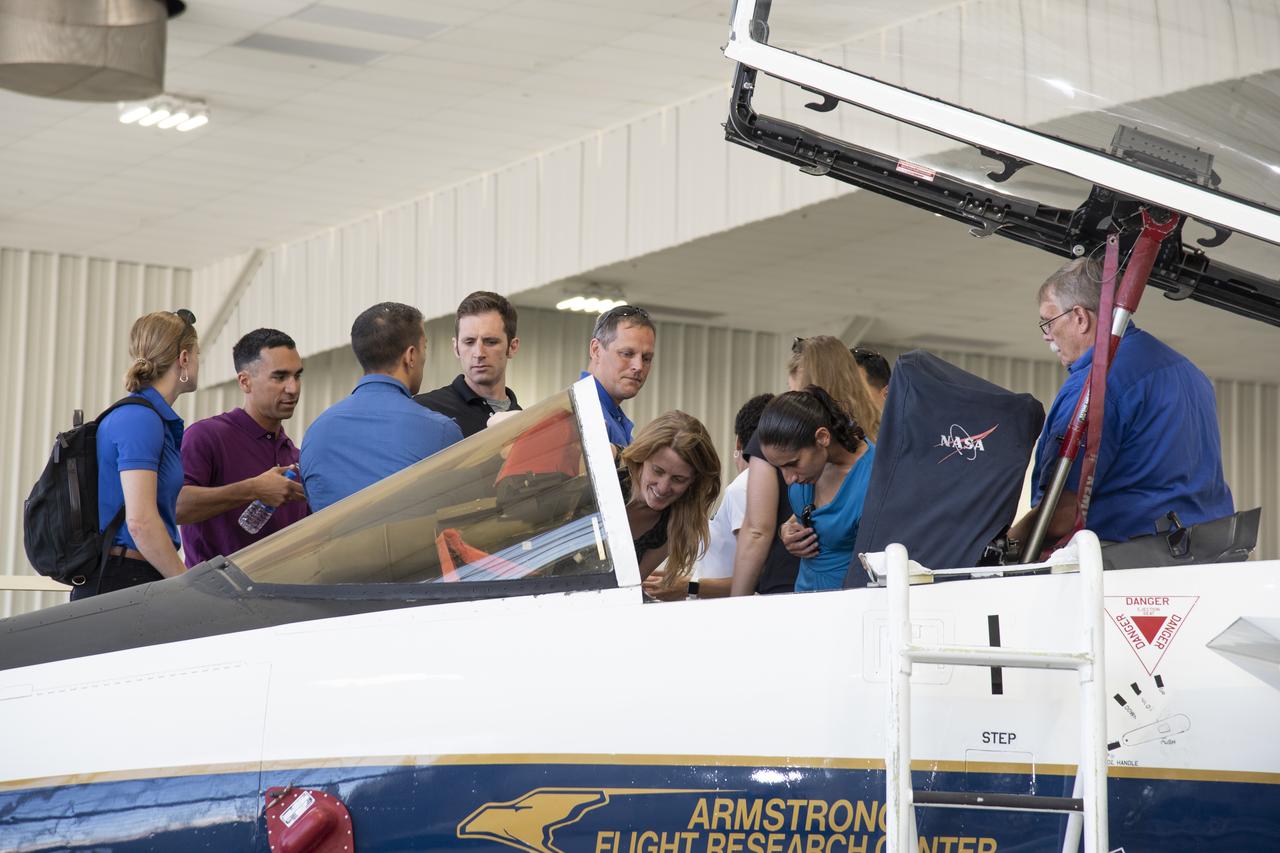
NASA's 2017 astronaut candidates toured aircraft hangar at Armstrong Flight Research Center, in Southern California where they checked out a F-15 cockpit. The center is using its fleet of supersonic research support aircraft for sonic boom research, including the F-15, which will fly in tandem with the X-59 QueSST during early flight test stages, and the F-18, which is conducting supersonic research in support of the overall mission.
NASA's 2017 astronaut candidates toured aircraft hangar at Armstrong Flight Research Center, in Southern California where they checked out a F-15 cockpit. The center is using its fleet of supersonic research support aircraft for sonic boom research, including the F-15, which will fly in tandem with the X-59 QueSST during early flight test stages, and the F-18, which is conducting supersonic research in support of the overall mission.
NASA’s 2017 astronaut candidates toured aircraft hangar at Armstrong Flight Research Center, in Southern California where they checked out a F-15 cockpit. The center is using its fleet of supersonic research support aircraft for sonic boom research, including the F-15, which will fly in tandem with the X-59 QueSST during early flight test stages, and the F-18, which is conducting supersonic research in support of the overall mission.

This photograph shows an early moment of the first test flight of the Saturn V vehicle for the Apollo 4 mission, photographed by a ground tracking camera, on the morning of November 9, 1967. This mission was the first launch of the Saturn V launch vehicle. Objectives of the unmarned Apollo 4 test flight were to obtain flight information on launch vehicle and spacecraft structural integrity and compatibility, flight loads, stage separation, and subsystems operation including testing of restart of the S-IVB stage, and to evaluate the Apollo command module heat shield.
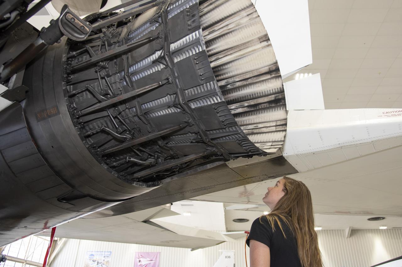
NASA’s 2017 astronaut candidates toured aircraft hangar at Armstrong Flight Research Center, in Southern California where Jenni Sidey-Gibbons looks inside engine nozzle of F-15 jet. The F-15 will fly in tandem with the X-59 QueSST during early flight test stages for the X-59 development.
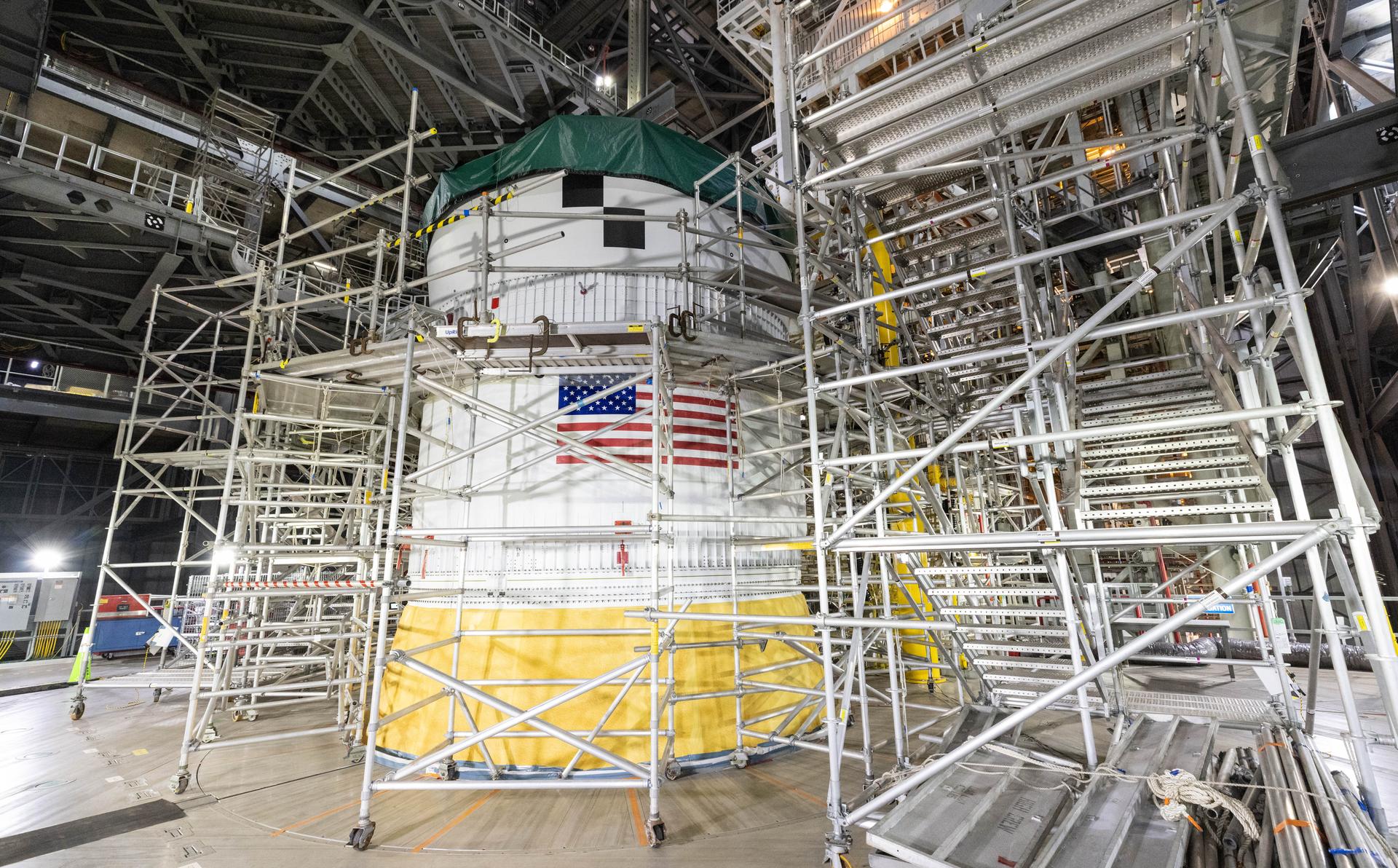
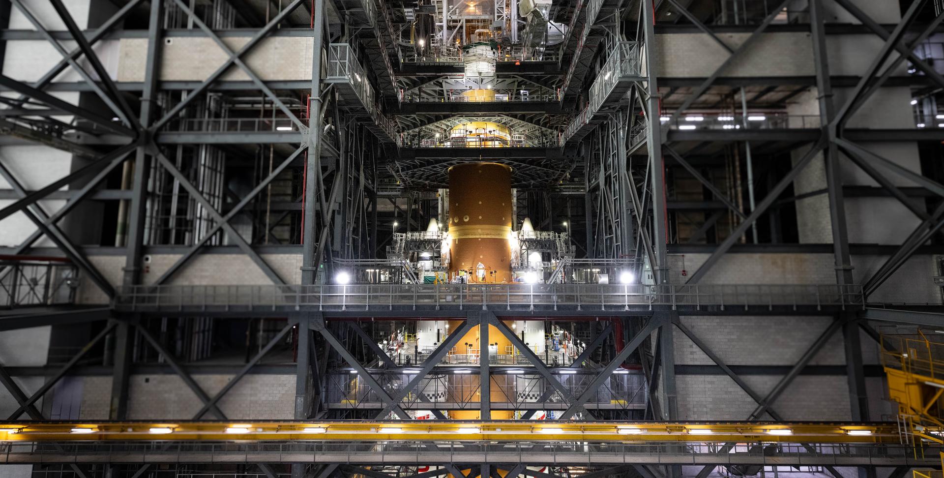
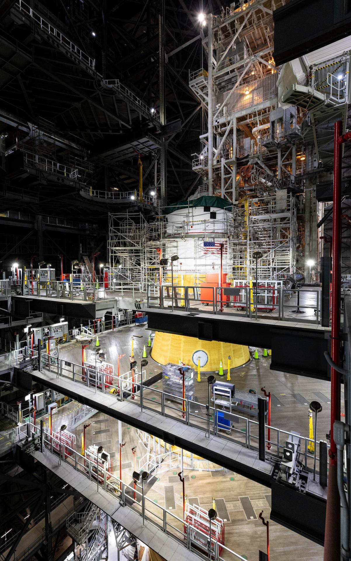
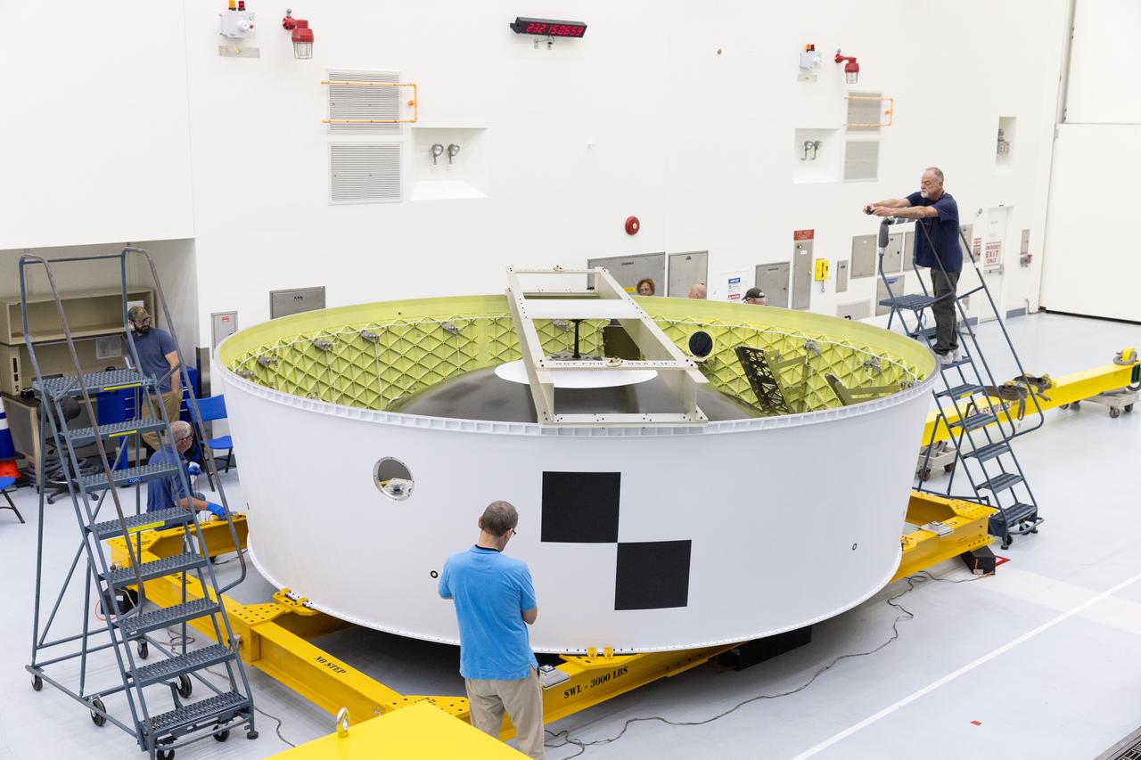
Technicians with NASA’s Exploration Ground Systems Program attach the Orion stage adapter to the interim cryogenic propulsion stage atop the agency’s SLS (Space Launch System) Moon rocket inside Vehicle Assembly Building at NASA’s Kennedy Space Center on Wednesday, Sept. 30, 2025. During the Artemis II test flight, the Orion stage adapter separates from the interim cryogenic propulsion stage, deploying four science payloads into high-Earth orbit. Up next, the Orion spacecraft and its launch abort system will stack atop the Orion stage adapter to complete integration and prepare for the launch of four astronauts around the Moon and back in early 2026.
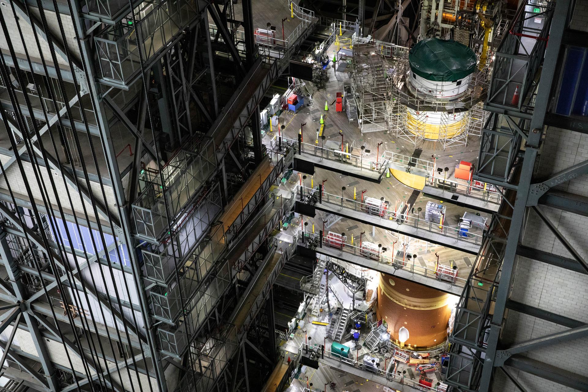
Technicians with NASA’s Exploration Ground Systems Program attach the Orion stage adapter to the interim cryogenic propulsion stage atop the agency’s SLS (Space Launch System) Moon rocket inside Vehicle Assembly Building at NASA’s Kennedy Space Center on Wednesday, Sept. 30, 2025. During the Artemis II test flight, the Orion stage adapter separates from the interim cryogenic propulsion stage, deploying four science payloads into high-Earth orbit. Up next, the Orion spacecraft and its launch abort system will stack atop the Orion stage adapter to complete integration and prepare for the launch of four astronauts around the Moon and back in early 2026.
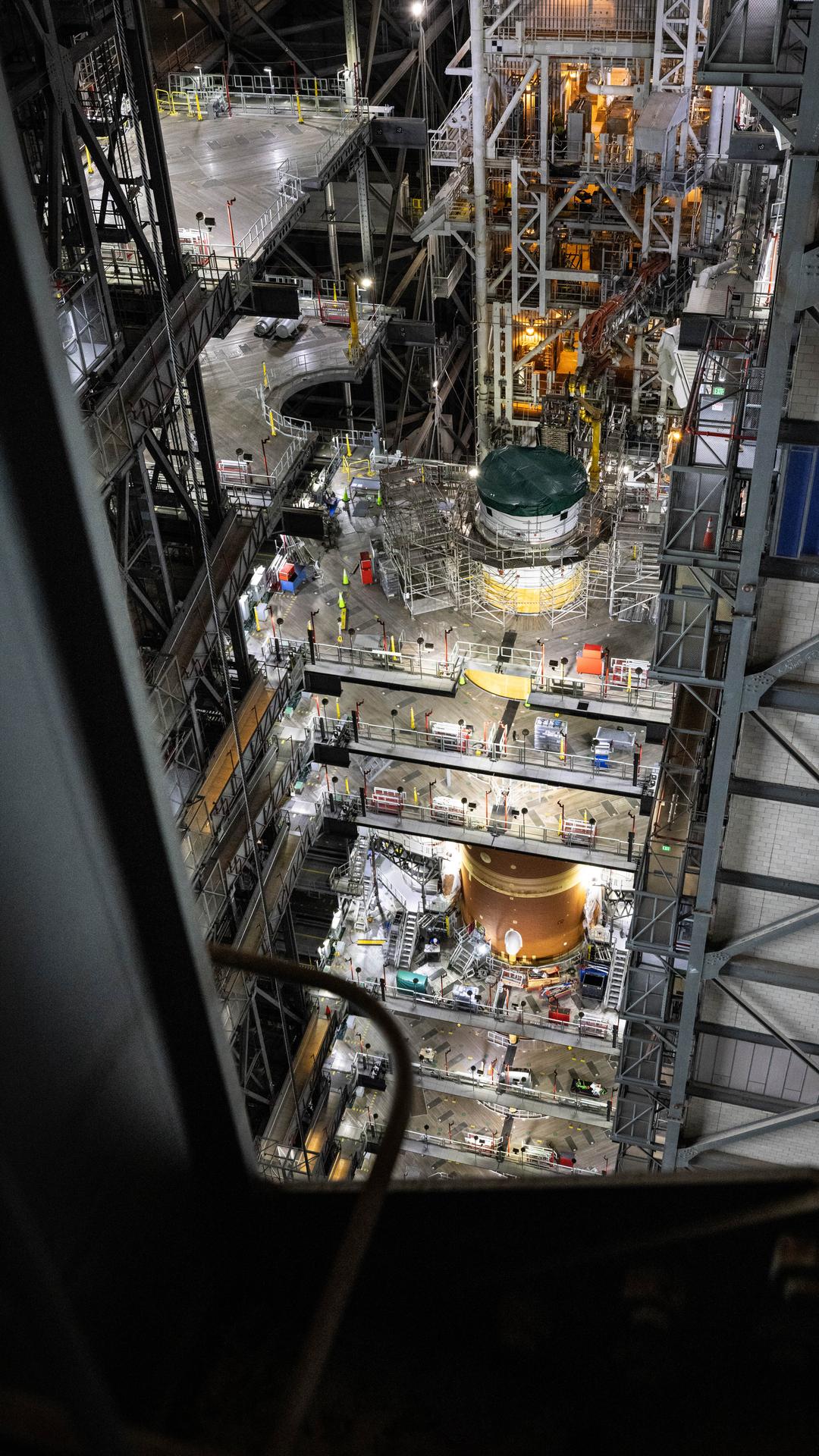
Technicians with NASA’s Exploration Ground Systems Program attach the Orion stage adapter to the interim cryogenic propulsion stage atop the agency’s SLS (Space Launch System) Moon rocket inside Vehicle Assembly Building at NASA’s Kennedy Space Center on Wednesday, Sept. 30, 2025. During the Artemis II test flight, the Orion stage adapter separates from the interim cryogenic propulsion stage, deploying four science payloads into high-Earth orbit. Up next, the Orion spacecraft and its launch abort system will stack atop the Orion stage adapter to complete integration and prepare for the launch of four astronauts around the Moon and back in early 2026.
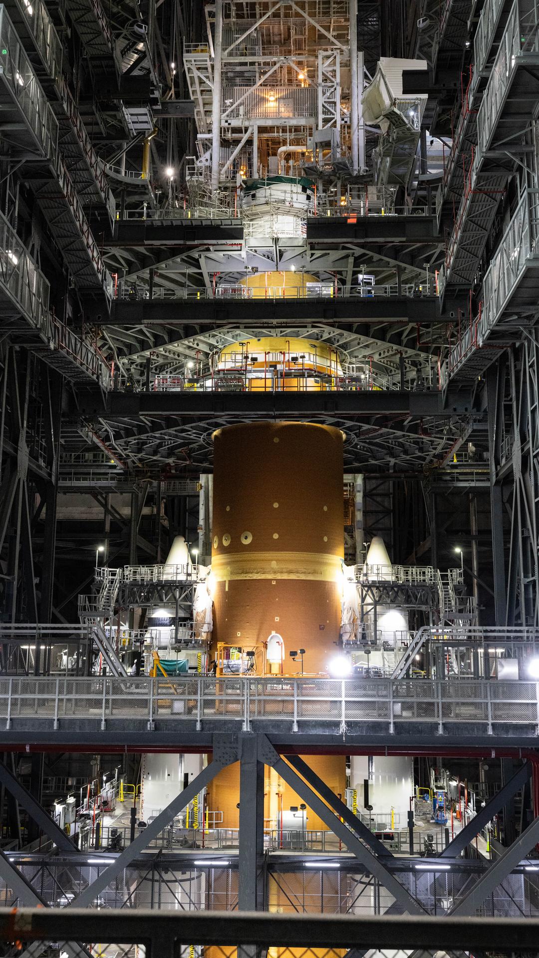
Technicians with NASA’s Exploration Ground Systems Program attach the Orion stage adapter to the interim cryogenic propulsion stage atop the agency’s SLS (Space Launch System) Moon rocket inside Vehicle Assembly Building at NASA’s Kennedy Space Center on Wednesday, Sept. 30, 2025. During the Artemis II test flight, the Orion stage adapter separates from the interim cryogenic propulsion stage, deploying four science payloads into high-Earth orbit. Up next, the Orion spacecraft and its launch abort system will stack atop the Orion stage adapter to complete integration and prepare for the launch of four astronauts around the Moon and back in early 2026.
Technicians with NASA’s Exploration Ground Systems Program attach the Orion stage adapter to the interim cryogenic propulsion stage atop the agency’s SLS (Space Launch System) Moon rocket inside Vehicle Assembly Building at NASA’s Kennedy Space Center on Wednesday, Sept. 30, 2025. During the Artemis II test flight, the Orion stage adapter separates from the interim cryogenic propulsion stage, deploying four science payloads into high-Earth orbit. Up next, the Orion spacecraft and its launch abort system will stack atop the Orion stage adapter to complete integration and prepare for the launch of four astronauts around the Moon and back in early 2026.
Technicians with NASA’s Exploration Ground Systems Program attach the Orion stage adapter to the interim cryogenic propulsion stage atop the agency’s SLS (Space Launch System) Moon rocket inside Vehicle Assembly Building at NASA’s Kennedy Space Center on Wednesday, Sept. 30, 2025. During the Artemis II test flight, the Orion stage adapter separates from the interim cryogenic propulsion stage, deploying four science payloads into high-Earth orbit. Up next, the Orion spacecraft and its launch abort system will stack atop the Orion stage adapter to complete integration and prepare for the launch of four astronauts around the Moon and back in early 2026.

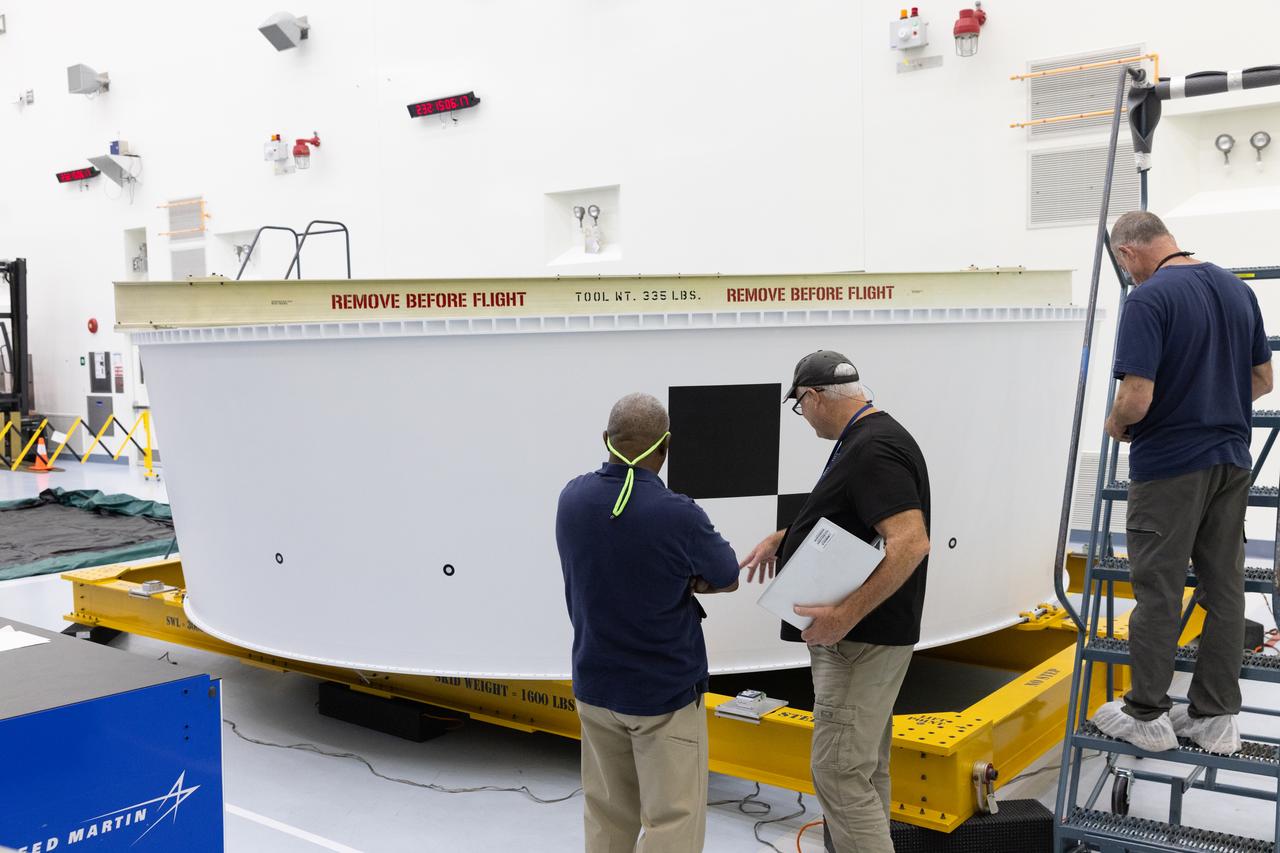
Technicians at NASA’s Kennedy Space Center in Florida complete routine inspections the Artemis II Orion stage adapter on Wednesday, Aug. 20, 2025, to the spaceport’s Multi-Payload Processing Facility to undergo CubeSat integration following its arrival from the agency’s Marshall Flight Center in Huntsville, Alabama. NASA Marshall built the Orion stage adapter which connects to the SLS (Space Launch System) rocket’s interim cryogenic propulsion stage to the Orion spacecraft and protects Orion from flammable gases generated during launch. The Artemis II test flight will take four astronauts around the Moon and return them back home in early 2026.
Technicians at NASA’s Kennedy Space Center in Florida complete routine inspections the Artemis II Orion stage adapter on Wednesday, Aug. 20, 2025, to the spaceport’s Multi-Payload Processing Facility to undergo CubeSat integration following its arrival from the agency’s Marshall Space Flight Center in Huntsville, Alabama. NASA Marshall built the Orion stage adapter which connects to the SLS (Space Launch System) rocket’s interim cryogenic propulsion stage to the Orion spacecraft and protects Orion from flammable gases generated during launch. The Artemis II test flight will take four astronauts around the Moon and return them back home in early 2026.
Technicians at NASA’s Kennedy Space Center in Florida complete routine inspections the Artemis II Orion stage adapter on Wednesday, Aug. 20, 2025, to the spaceport’s Multi-Payload Processing Facility to undergo CubeSat integration following its arrival from the agency’s Marshall Space Flight Center in Huntsville, Alabama. NASA Marshall built the Orion stage adapter which connects to the SLS (Space Launch System) rocket’s interim cryogenic propulsion stage to the Orion spacecraft and protects Orion from flammable gases generated during launch. The Artemis II test flight will take four astronauts around the Moon and return them back home in early 2026.

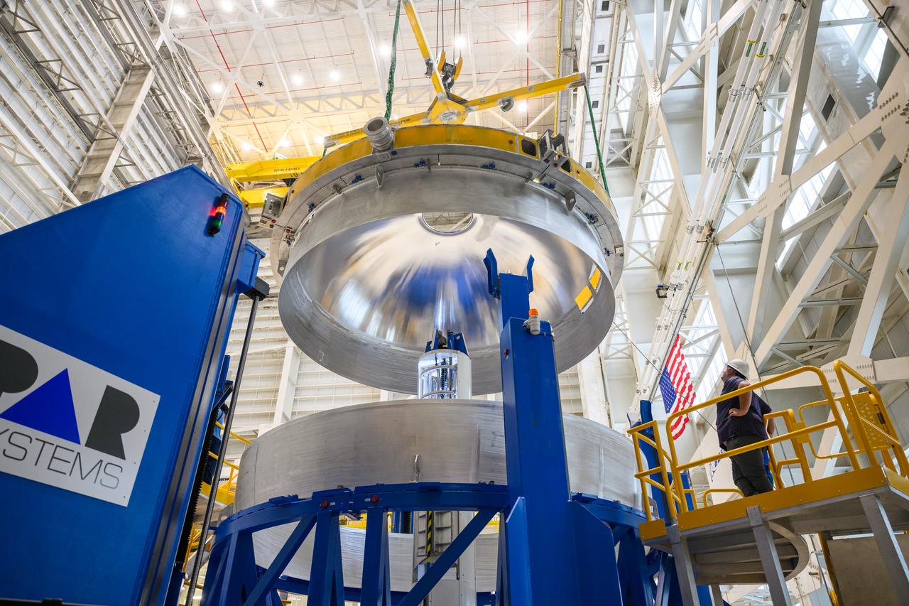
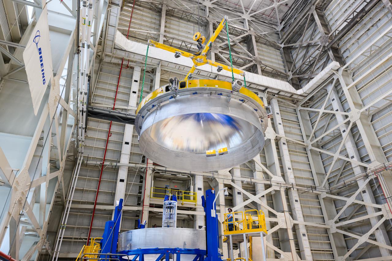
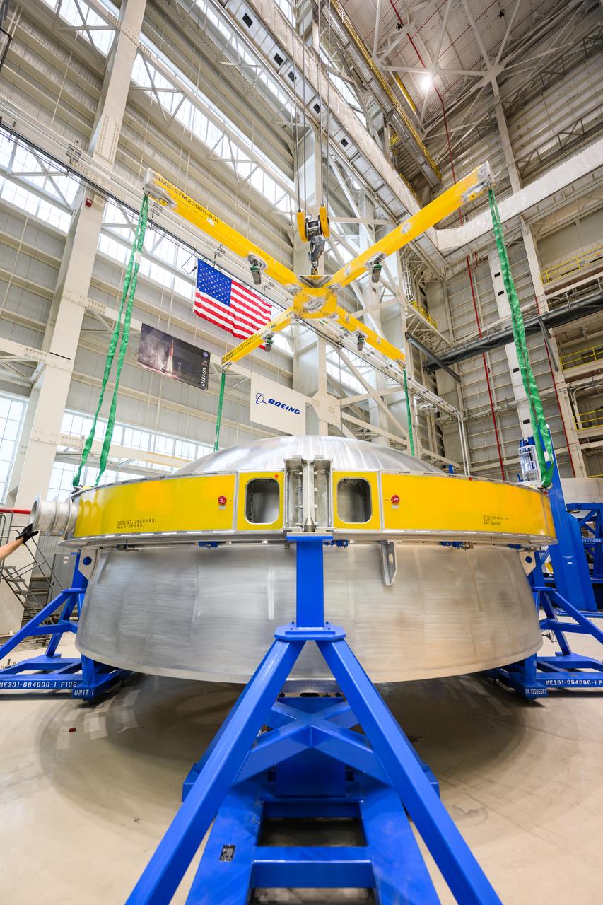
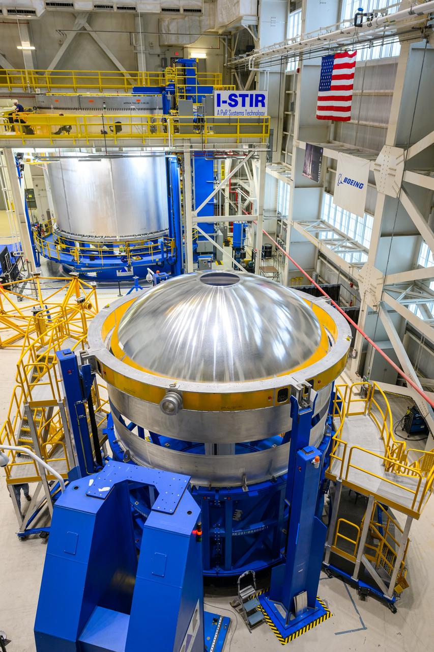
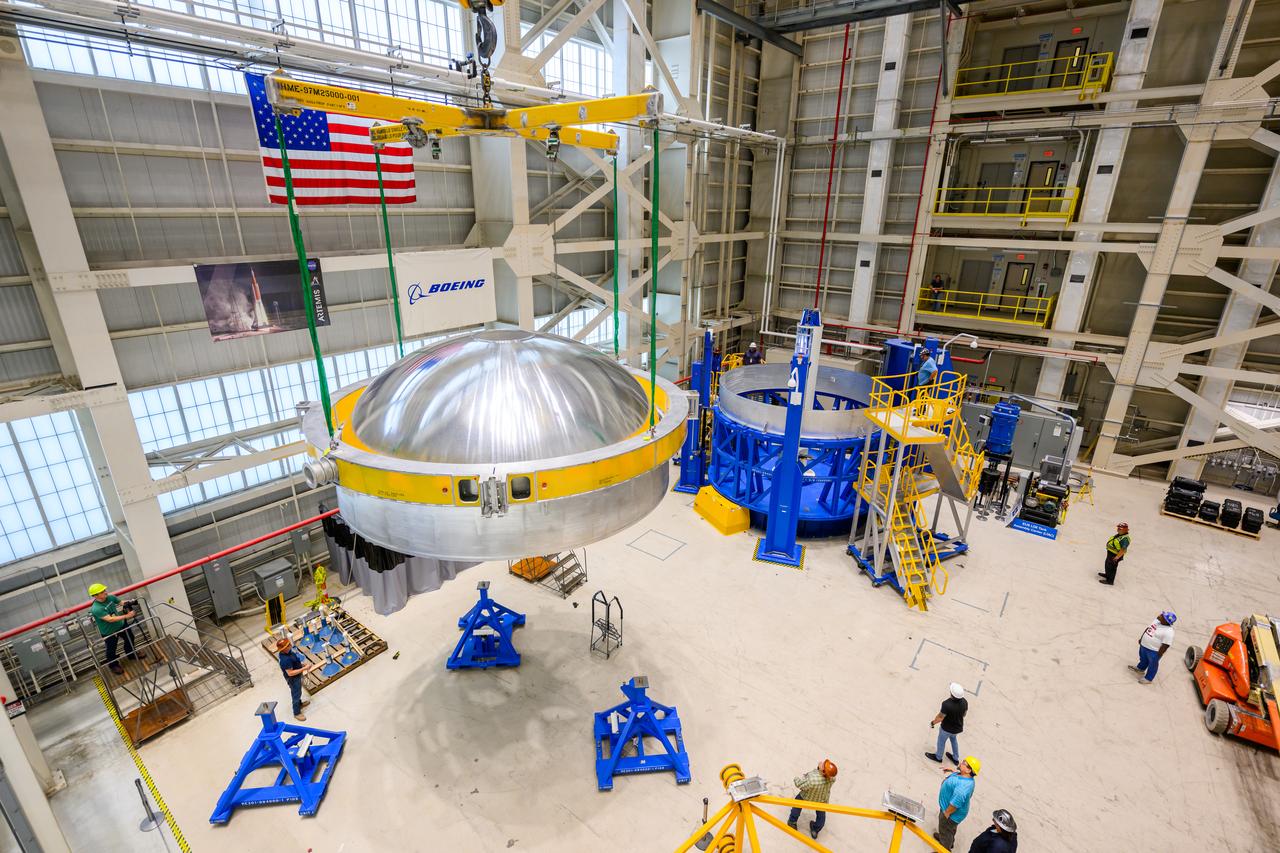
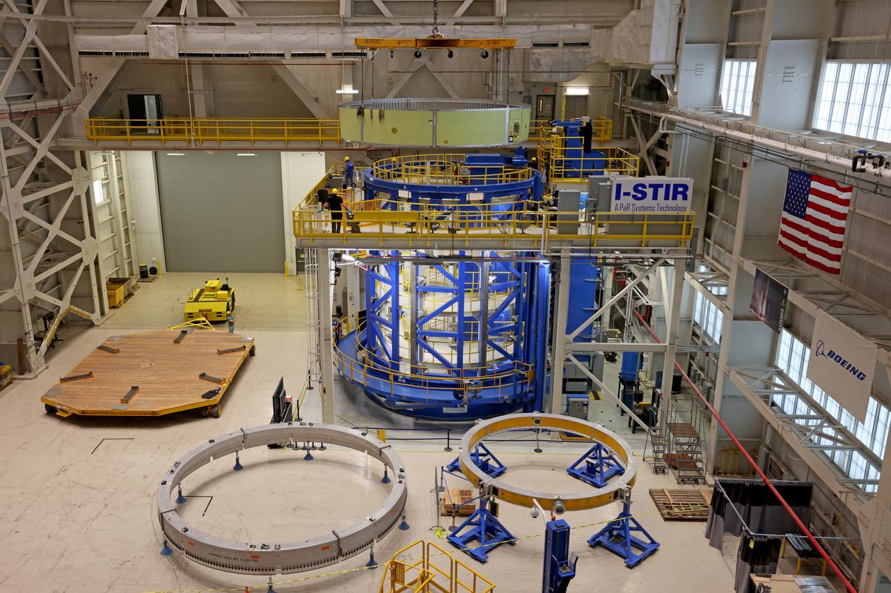
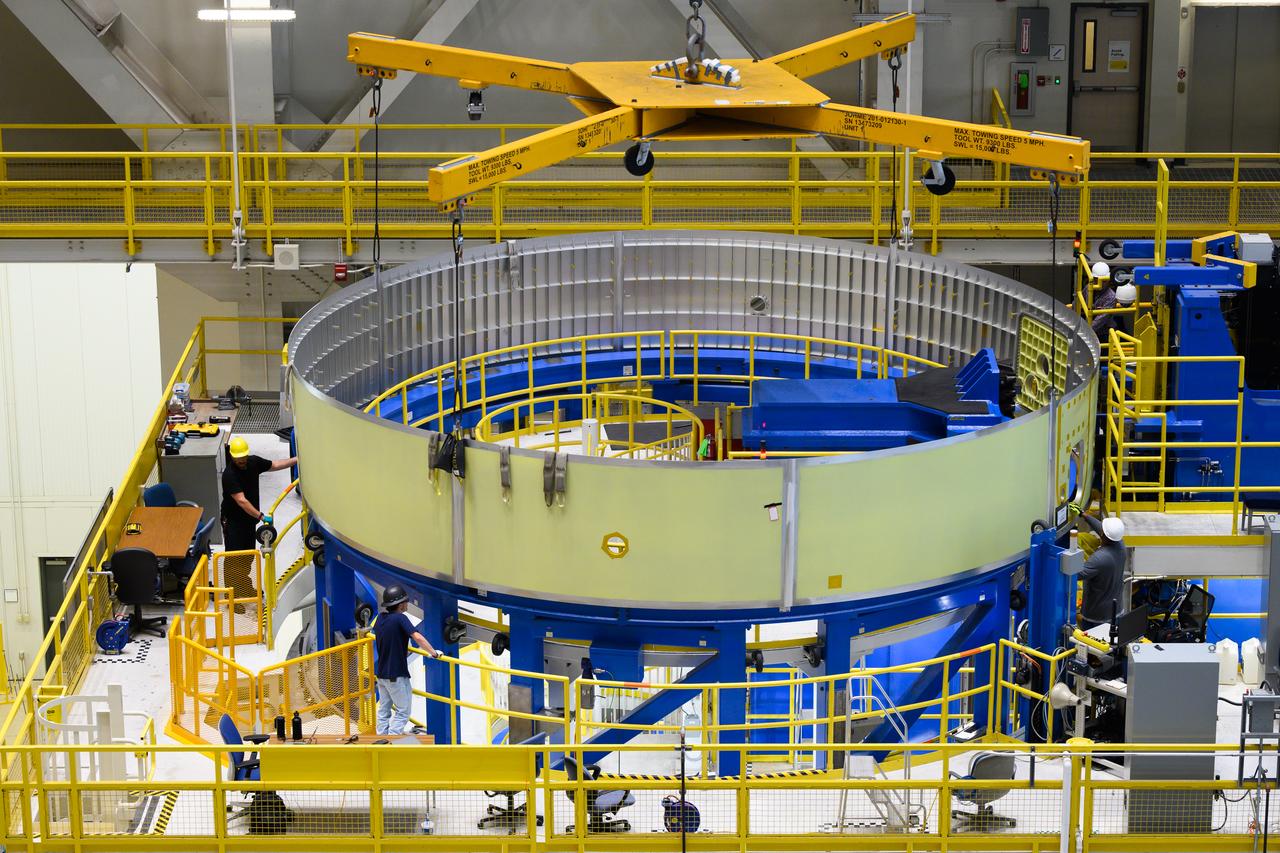
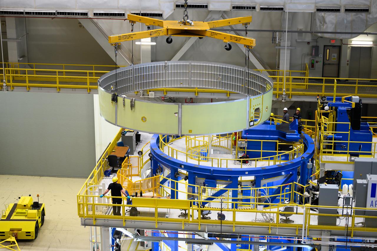
These images show technicians at NASA’s Michoud Assembly Facility in New Orleans lifting and installing the liquid oxygen dome weld confidence article for a future upper stage for NASA’s SLS (Space Launch System) rocket onto the LTAC (LOX Tank Assembly Center) in Building 115 at Michoud for the next phase of manufacturing in July 2023. The dome makes up a portion of the liquid oxygen tank weld confidence article for the EUS (exploration upper stage). Teams use weld confidence articles to verify welding procedures and structural integrity of the welds to manufacture structural test and flight versions of the hardware. EUS flight hardware is in early production at Michoud. The more powerful upper stage and its four RL10 engines will be used on the second configuration of the SLS rocket, known as Block 1B, and will provide in-space propulsion to send astronauts in NASA’s Orion spacecraft and heavy cargo on a precise trajectory to the Moon. NASA and Boeing, the lead contractor for the SLS core stage and EUS, are manufacturing SLS stages for Artemis II, III, IV, and V at the facility. NASA is working to land the first woman and first person of color on the Moon under Artemis. SLS is part of NASA’s backbone for deep space exploration, along with Orion and the Gateway in orbit around the Moon. SLS is the only rocket that can send Orion, astronauts, and supplies to the Moon in a single mission.
These images show technicians at NASA’s Michoud Assembly Facility in New Orleans lifting and installing the liquid oxygen dome weld confidence article for a future upper stage for NASA’s SLS (Space Launch System) rocket onto the LTAC (LOX Tank Assembly Center) in Building 115 at Michoud for the next phase of manufacturing in July 2023. The dome makes up a portion of the liquid oxygen tank weld confidence article for the EUS (exploration upper stage). Teams use weld confidence articles to verify welding procedures and structural integrity of the welds to manufacture structural test and flight versions of the hardware. EUS flight hardware is in early production at Michoud. The more powerful upper stage and its four RL10 engines will be used on the second configuration of the SLS rocket, known as Block 1B, and will provide in-space propulsion to send astronauts in NASA’s Orion spacecraft and heavy cargo on a precise trajectory to the Moon. NASA and Boeing, the lead contractor for the SLS core stage and EUS, are manufacturing SLS stages for Artemis II, III, IV, and V at the facility. NASA is working to land the first woman and first person of color on the Moon under Artemis. SLS is part of NASA’s backbone for deep space exploration, along with Orion and the Gateway in orbit around the Moon. SLS is the only rocket that can send Orion, astronauts, and supplies to the Moon in a single mission.
These images show technicians at NASA’s Michoud Assembly Facility in New Orleans lifting and installing the liquid oxygen dome weld confidence article for a future upper stage for NASA’s SLS (Space Launch System) rocket onto the LTAC (LOX Tank Assembly Center) in Building 115 at Michoud for the next phase of manufacturing in July 2023. The dome makes up a portion of the liquid oxygen tank weld confidence article for the EUS (exploration upper stage). Teams use weld confidence articles to verify welding procedures and structural integrity of the welds to manufacture structural test and flight versions of the hardware. EUS flight hardware is in early production at Michoud. The more powerful upper stage and its four RL10 engines will be used on the second configuration of the SLS rocket, known as Block 1B, and will provide in-space propulsion to send astronauts in NASA’s Orion spacecraft and heavy cargo on a precise trajectory to the Moon. NASA and Boeing, the lead contractor for the SLS core stage and EUS, are manufacturing SLS stages for Artemis II, III, IV, and V at the facility. NASA is working to land the first woman and first person of color on the Moon under Artemis. SLS is part of NASA’s backbone for deep space exploration, along with Orion and the Gateway in orbit around the Moon. SLS is the only rocket that can send Orion, astronauts, and supplies to the Moon in a single mission.
These images show technicians at NASA’s Michoud Assembly Facility in New Orleans lifting and installing the liquid oxygen dome weld confidence article for a future upper stage for NASA’s SLS (Space Launch System) rocket onto the LTAC (LOX Tank Assembly Center) in Building 115 at Michoud for the next phase of manufacturing in July 2023. The dome makes up a portion of the liquid oxygen tank weld confidence article for the EUS (exploration upper stage). Teams use weld confidence articles to verify welding procedures and structural integrity of the welds to manufacture structural test and flight versions of the hardware. EUS flight hardware is in early production at Michoud. The more powerful upper stage and its four RL10 engines will be used on the second configuration of the SLS rocket, known as Block 1B, and will provide in-space propulsion to send astronauts in NASA’s Orion spacecraft and heavy cargo on a precise trajectory to the Moon. NASA and Boeing, the lead contractor for the SLS core stage and EUS, are manufacturing SLS stages for Artemis II, III, IV, and V at the facility. NASA is working to land the first woman and first person of color on the Moon under Artemis. SLS is part of NASA’s backbone for deep space exploration, along with Orion and the Gateway in orbit around the Moon. SLS is the only rocket that can send Orion, astronauts, and supplies to the Moon in a single mission.
These images show technicians at NASA’s Michoud Assembly Facility in New Orleans lifting and installing the liquid oxygen dome weld confidence article for a future upper stage for NASA’s SLS (Space Launch System) rocket onto the LTAC (LOX Tank Assembly Center) in Building 115 at Michoud for the next phase of manufacturing in July 2023. The dome makes up a portion of the liquid oxygen tank weld confidence article for the EUS (exploration upper stage). Teams use weld confidence articles to verify welding procedures and structural integrity of the welds to manufacture structural test and flight versions of the hardware. EUS flight hardware is in early production at Michoud. The more powerful upper stage and its four RL10 engines will be used on the second configuration of the SLS rocket, known as Block 1B, and will provide in-space propulsion to send astronauts in NASA’s Orion spacecraft and heavy cargo on a precise trajectory to the Moon. NASA and Boeing, the lead contractor for the SLS core stage and EUS, are manufacturing SLS stages for Artemis II, III, IV, and V at the facility. NASA is working to land the first woman and first person of color on the Moon under Artemis. SLS is part of NASA’s backbone for deep space exploration, along with Orion and the Gateway in orbit around the Moon. SLS is the only rocket that can send Orion, astronauts, and supplies to the Moon in a single mission.
These images show technicians at NASA’s Michoud Assembly Facility in New Orleans lifting and installing the liquid oxygen dome weld confidence article for a future upper stage for NASA’s SLS (Space Launch System) rocket onto the LTAC (LOX Tank Assembly Center) in Building 115 at Michoud for the next phase of manufacturing in July 2023. The dome makes up a portion of the liquid oxygen tank weld confidence article for the EUS (exploration upper stage). Teams use weld confidence articles to verify welding procedures and structural integrity of the welds to manufacture structural test and flight versions of the hardware. EUS flight hardware is in early production at Michoud. The more powerful upper stage and its four RL10 engines will be used on the second configuration of the SLS rocket, known as Block 1B, and will provide in-space propulsion to send astronauts in NASA’s Orion spacecraft and heavy cargo on a precise trajectory to the Moon. NASA and Boeing, the lead contractor for the SLS core stage and EUS, are manufacturing SLS stages for Artemis II, III, IV, and V at the facility. NASA is working to land the first woman and first person of color on the Moon under Artemis. SLS is part of NASA’s backbone for deep space exploration, along with Orion and the Gateway in orbit around the Moon. SLS is the only rocket that can send Orion, astronauts, and supplies to the Moon in a single mission.

The first RS-25 flight engine, engine No. 2059, is lifted onto the A-1 Test Stand at Stennis Space Center on Nov. 4, 2015. The engine was tested in early 2016 to certify it for use on NASA’s new Space Launch System (SLS). The SLS core stage will be powered by four RS-25 engines, all tested at Stennis Space Center. NASA is developing the SLS to carry humans deeper into space than ever before, including on a journey to Mars.
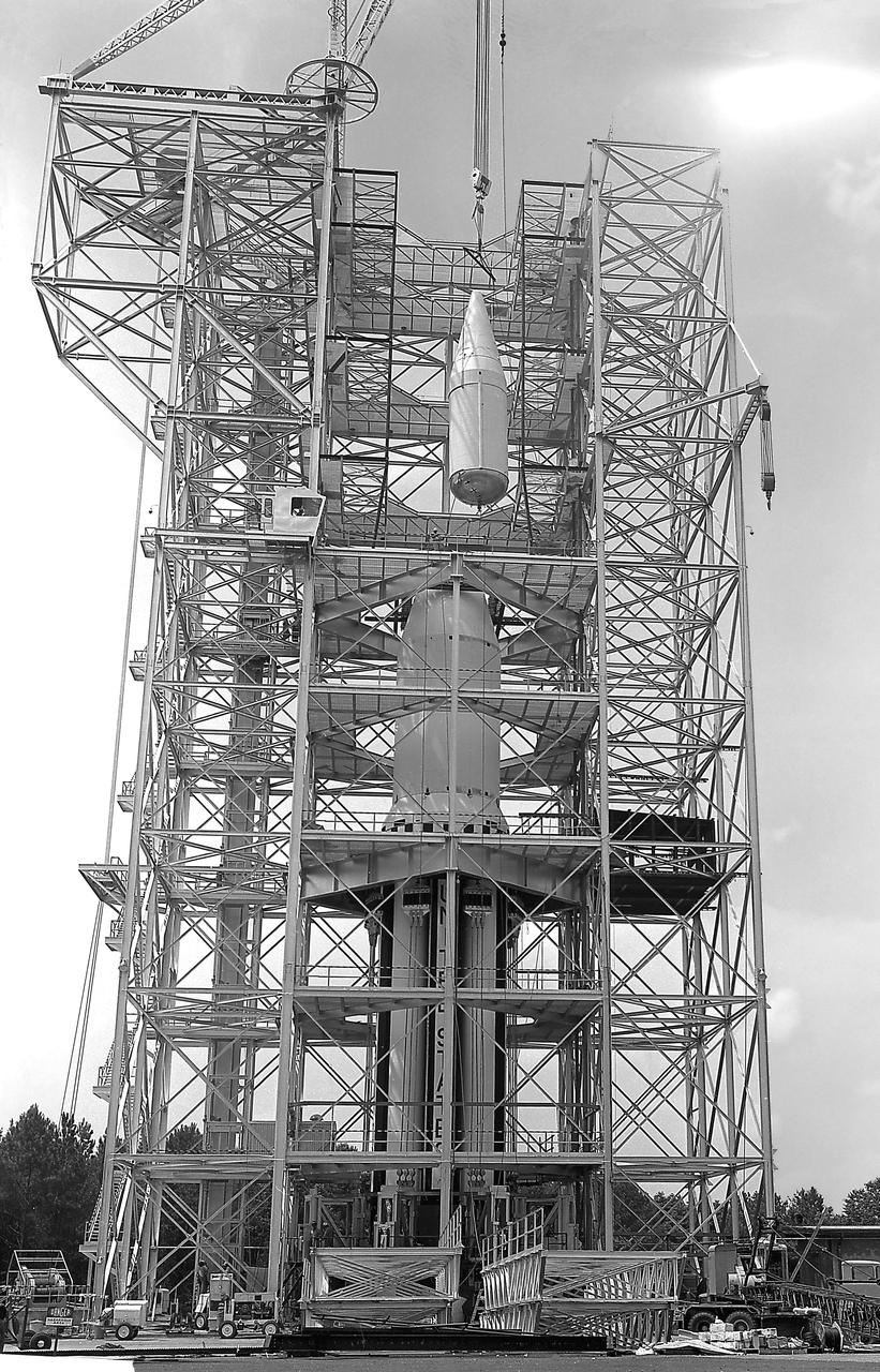
This image depicts the Saturn I launch vehicle placed in the dynamic test stand at the Marshall Space Flight Center (MSFC). A dummy booster was moved to the dynamic test stand early in June, and, for the first time, vertically mated with dummy S-I and S-IV stages. The assembled vehicle was readied for dynamic testing to investigate the integrity of the support structure.
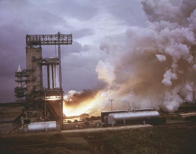
Marshall Space Flight Center (MSFC) was the birthplace of the United States' rocket program. In the early 1960s, most of the rocket development and testing were done at the MSFC. Pictured is an example of what the test engineers would have seen from the pillbox as eight H-1 engines for the first stage of the Saturn I rocket were test fired.
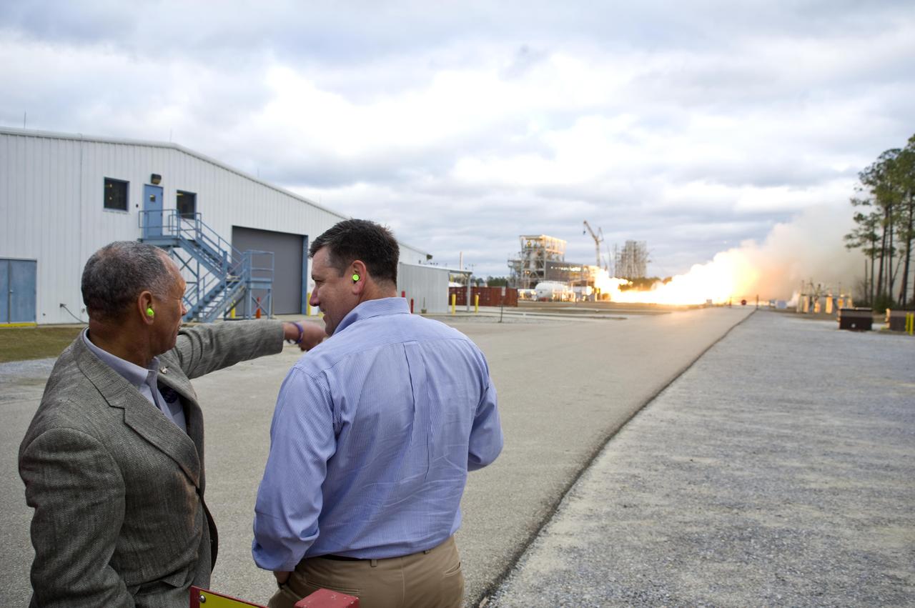
NASA Administrator Charles Bolden (l) and John C. Stennis Space Center Director Patrick Scheuermann watch the successful test of the first Aerojet AJ26 flight engine Feb. 7, 2011. The test was conducted on the E-1 Test Stand at Stennis. The engine now will be sent to Wallops Flight Facility in Virginia, where it will be used to power the first stage of Orbital Sciences Corporation's Taurus II space vehicle. The Feb. 7 test supports NASA's commitment to partner with companies to provide commercial cargo flights to the International Space Station. NASA has partnered with Orbital to carry out the first of eight cargo missions to the space station in early 2012.
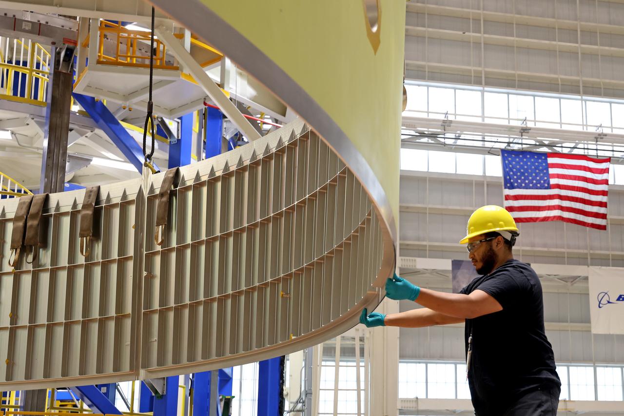
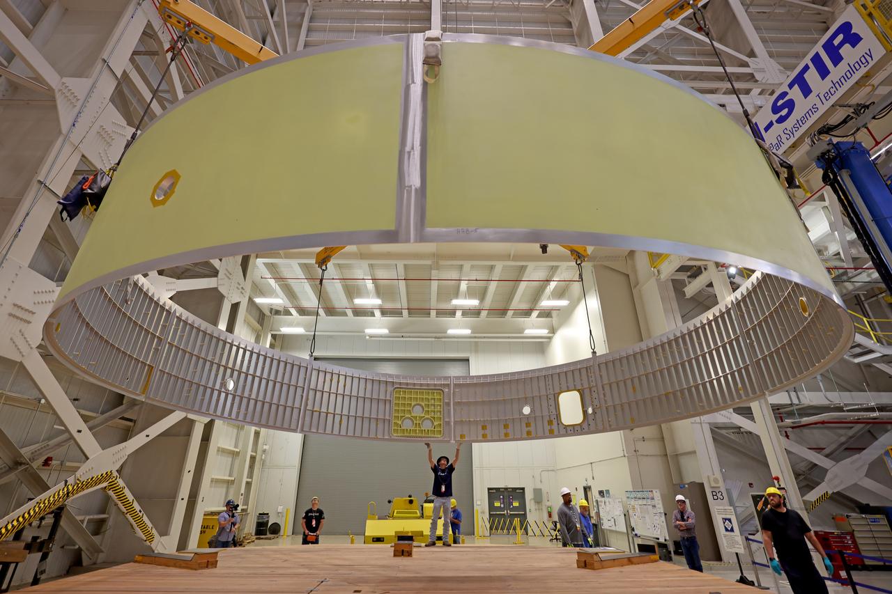
These images and videos show technicians at NASA’s Michoud Assembly Facility in New Orleans examining and lifting midbody barrels for the Exploration Upper Stage (EUS) structural test article of the SLS (Space Launch System) rocket in May 2023. The barrel sections make up the body, or main structure, of the future in-space propulsion stage for the mega rocket. The Exploration Upper Stage will be used on the second configuration of the SLS rocket, known as Block 1B, and will provide in-space propulsion to send astronauts in NASA’s Orion spacecraft and heavy cargo on a precise trajectory to the Moon. Beginning with Artemis IV, EUS will replace the interim cryogenic propulsion stage for the Block 1 configuration of SLS. It has larger propellant tanks and four RL10 engines, enabling SLS to launch 40% more cargo to the Moon along with crew. EUS flight hardware is in early production at Michoud. Crews with NASA and Boeing, the lead contractor for the SLS core stage and EUS, are also manufacturing the EUS structural test article. The test hardware is structurally identical to the flight version and will be used during a series of strenuous testing that simulates the forces the rocket will experience during launch and flight and verify its structural integrity. NASA is working to land the first woman and first person of color on the Moon under Artemis. SLS is part of NASA’s backbone for deep space exploration, along with Orion and the Gateway in orbit around the Moon. SLS is the only rocket that can send Orion, astronauts, and supplies to the Moon in a single mission.
These images and videos show technicians at NASA’s Michoud Assembly Facility in New Orleans examining and lifting midbody barrels for the Exploration Upper Stage (EUS) structural test article of the SLS (Space Launch System) rocket in May 2023. The barrel sections make up the body, or main structure, of the future in-space propulsion stage for the mega rocket. The Exploration Upper Stage will be used on the second configuration of the SLS rocket, known as Block 1B, and will provide in-space propulsion to send astronauts in NASA’s Orion spacecraft and heavy cargo on a precise trajectory to the Moon. Beginning with Artemis IV, EUS will replace the interim cryogenic propulsion stage for the Block 1 configuration of SLS. It has larger propellant tanks and four RL10 engines, enabling SLS to launch 40% more cargo to the Moon along with crew. EUS flight hardware is in early production at Michoud. Crews with NASA and Boeing, the lead contractor for the SLS core stage and EUS, are also manufacturing the EUS structural test article. The test hardware is structurally identical to the flight version and will be used during a series of strenuous testing that simulates the forces the rocket will experience during launch and flight and verify its structural integrity. NASA is working to land the first woman and first person of color on the Moon under Artemis. SLS is part of NASA’s backbone for deep space exploration, along with Orion and the Gateway in orbit around the Moon. SLS is the only rocket that can send Orion, astronauts, and supplies to the Moon in a single mission.
These images and videos show technicians at NASA’s Michoud Assembly Facility in New Orleans examining and lifting midbody barrels for the Exploration Upper Stage (EUS) structural test article of the SLS (Space Launch System) rocket in May 2023. The barrel sections make up the body, or main structure, of the future in-space propulsion stage for the mega rocket. The Exploration Upper Stage will be used on the second configuration of the SLS rocket, known as Block 1B, and will provide in-space propulsion to send astronauts in NASA’s Orion spacecraft and heavy cargo on a precise trajectory to the Moon. Beginning with Artemis IV, EUS will replace the interim cryogenic propulsion stage for the Block 1 configuration of SLS. It has larger propellant tanks and four RL10 engines, enabling SLS to launch 40% more cargo to the Moon along with crew. EUS flight hardware is in early production at Michoud. Crews with NASA and Boeing, the lead contractor for the SLS core stage and EUS, are also manufacturing the EUS structural test article. The test hardware is structurally identical to the flight version and will be used during a series of strenuous testing that simulates the forces the rocket will experience during launch and flight and verify its structural integrity. NASA is working to land the first woman and first person of color on the Moon under Artemis. SLS is part of NASA’s backbone for deep space exploration, along with Orion and the Gateway in orbit around the Moon. SLS is the only rocket that can send Orion, astronauts, and supplies to the Moon in a single mission.

These images and videos show technicians at NASA’s Michoud Assembly Facility in New Orleans examining and lifting midbody barrels for the Exploration Upper Stage (EUS) structural test article of the SLS (Space Launch System) rocket in May 2023. The barrel sections make up the body, or main structure, of the future in-space propulsion stage for the mega rocket. The Exploration Upper Stage will be used on the second configuration of the SLS rocket, known as Block 1B, and will provide in-space propulsion to send astronauts in NASA’s Orion spacecraft and heavy cargo on a precise trajectory to the Moon. Beginning with Artemis IV, EUS will replace the interim cryogenic propulsion stage for the Block 1 configuration of SLS. It has larger propellant tanks and four RL10 engines, enabling SLS to launch 40% more cargo to the Moon along with crew. EUS flight hardware is in early production at Michoud. Crews with NASA and Boeing, the lead contractor for the SLS core stage and EUS, are also manufacturing the EUS structural test article. The test hardware is structurally identical to the flight version and will be used during a series of strenuous testing that simulates the forces the rocket will experience during launch and flight and verify its structural integrity. NASA is working to land the first woman and first person of color on the Moon under Artemis. SLS is part of NASA’s backbone for deep space exploration, along with Orion and the Gateway in orbit around the Moon. SLS is the only rocket that can send Orion, astronauts, and supplies to the Moon in a single mission.
These images and videos show technicians at NASA’s Michoud Assembly Facility in New Orleans examining and lifting midbody barrels for the Exploration Upper Stage (EUS) structural test article of the SLS (Space Launch System) rocket in May 2023. The barrel sections make up the body, or main structure, of the future in-space propulsion stage for the mega rocket. The Exploration Upper Stage will be used on the second configuration of the SLS rocket, known as Block 1B, and will provide in-space propulsion to send astronauts in NASA’s Orion spacecraft and heavy cargo on a precise trajectory to the Moon. Beginning with Artemis IV, EUS will replace the interim cryogenic propulsion stage for the Block 1 configuration of SLS. It has larger propellant tanks and four RL10 engines, enabling SLS to launch 40% more cargo to the Moon along with crew. EUS flight hardware is in early production at Michoud. Crews with NASA and Boeing, the lead contractor for the SLS core stage and EUS, are also manufacturing the EUS structural test article. The test hardware is structurally identical to the flight version and will be used during a series of strenuous testing that simulates the forces the rocket will experience during launch and flight and verify its structural integrity. NASA is working to land the first woman and first person of color on the Moon under Artemis. SLS is part of NASA’s backbone for deep space exploration, along with Orion and the Gateway in orbit around the Moon. SLS is the only rocket that can send Orion, astronauts, and supplies to the Moon in a single mission.
These images and videos show technicians at NASA’s Michoud Assembly Facility in New Orleans examining and lifting midbody barrels for the Exploration Upper Stage (EUS) structural test article of the SLS (Space Launch System) rocket in May 2023. The barrel sections make up the body, or main structure, of the future in-space propulsion stage for the mega rocket. The Exploration Upper Stage will be used on the second configuration of the SLS rocket, known as Block 1B, and will provide in-space propulsion to send astronauts in NASA’s Orion spacecraft and heavy cargo on a precise trajectory to the Moon. Beginning with Artemis IV, EUS will replace the interim cryogenic propulsion stage for the Block 1 configuration of SLS. It has larger propellant tanks and four RL10 engines, enabling SLS to launch 40% more cargo to the Moon along with crew. EUS flight hardware is in early production at Michoud. Crews with NASA and Boeing, the lead contractor for the SLS core stage and EUS, are also manufacturing the EUS structural test article. The test hardware is structurally identical to the flight version and will be used during a series of strenuous testing that simulates the forces the rocket will experience during launch and flight and verify its structural integrity. NASA is working to land the first woman and first person of color on the Moon under Artemis. SLS is part of NASA’s backbone for deep space exploration, along with Orion and the Gateway in orbit around the Moon. SLS is the only rocket that can send Orion, astronauts, and supplies to the Moon in a single mission.
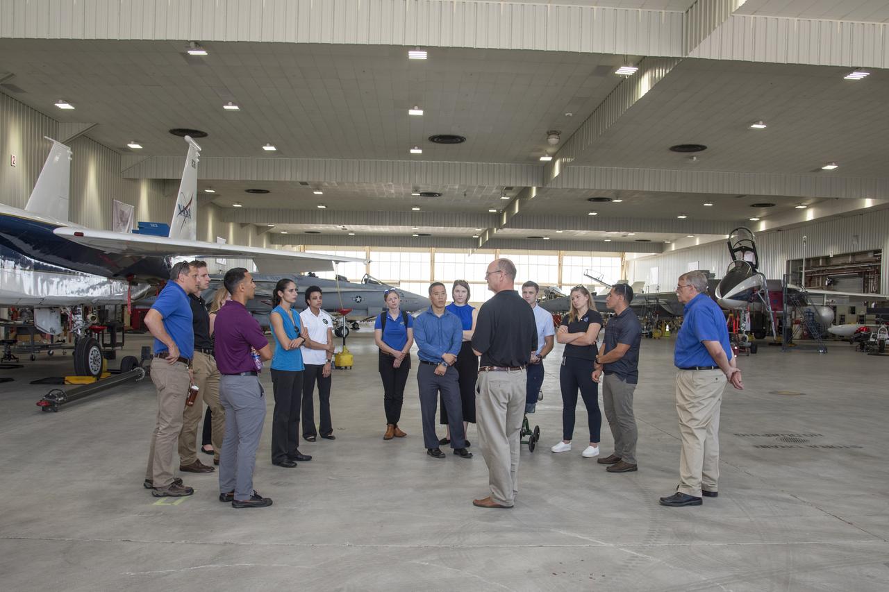
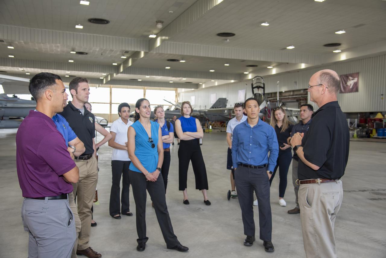
NASA's 2017 astronaut candidates toured aircraft hangar at Armstrong Flight Research Center, in Southern California. On the right, NASA's, X-59 pilot Nils Larsen, briefs the astronauts as they look at Armstrong's fleet of supersonic research support aircraft, including the F-15, which will fly in tandem with the X-59 QueSST during early flight test stages, and the F-18, which is conducting supersonic research in support of the overall mission.
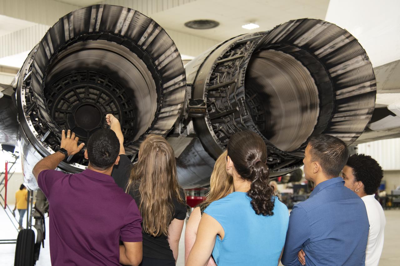
NASA's 2017 astronaut candidates toured aircraft hangar at Armstrong Flight Research Center, in Southern California (L to R) Raja Chari, Jenni Sidey-Gibbons, Loral O'Hara, Jasmin Moghbeli, Jonny Kim and Jessica Watkins look inside the engine nozzle of an F-15 jet. The F-15 will fly in tandem with the X-59 QueSST during early flight test stages for the X-59 development.
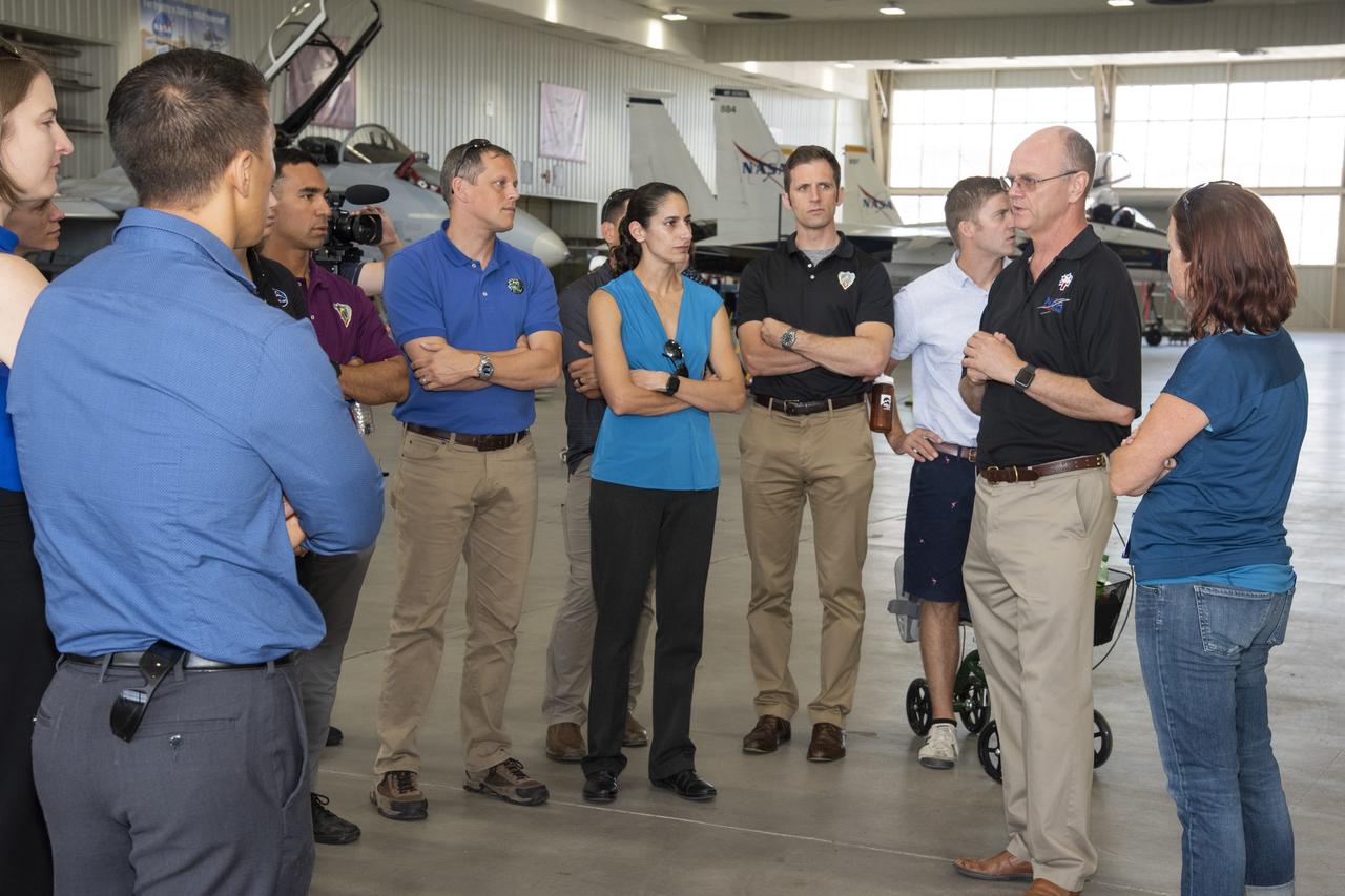
NASA’s 2017 astronaut candidates toured aircraft hangar at Armstrong Flight Research Center, in Southern California. On the right, NASA’s, X-59 pilot Nils Larsen, briefs the astronauts as they look at Armstrong’s fleet of supersonic research support aircraft, including the F-15, which will fly in tandem with the X-59 QueSST during early flight test stages, and the F-18, which is conducting supersonic research in support of the overall mission.
NASA's 2017 astronaut candidates toured aircraft hangar at Armstrong Flight Research Center, in Southern California. On the right, NASA's, X-59 pilot Nils Larsen, briefs the astronauts as they look at Armstrong's fleet of supersonic research support aircraft, including the F-15, which will fly in tandem with the X-59 QueSST during early flight test stages, and the F-18, which is conducting supersonic research in support of the overall mission.
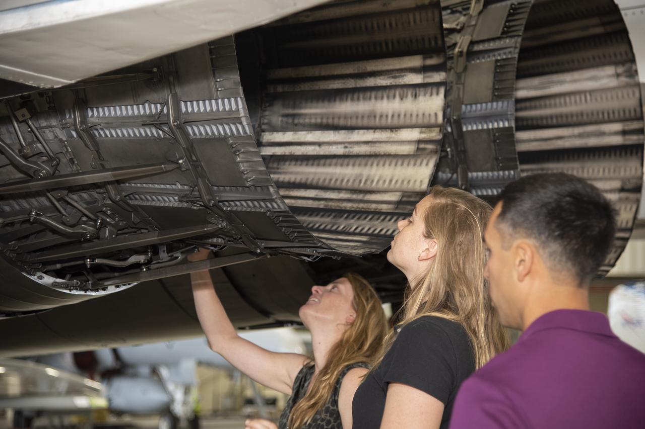
NASA's 2017 astronaut candidates toured aircraft hangar at Armstrong Flight Research Center, in Southern California where (L to R) Loral O'Hara, Jenni Sidey-Gibbons and Raja Chari look inside the engine nozzle of an F-15 jet. The F-15 will fly in tandem with the X-59 QueSST during early flight test stages for the X-59 development.
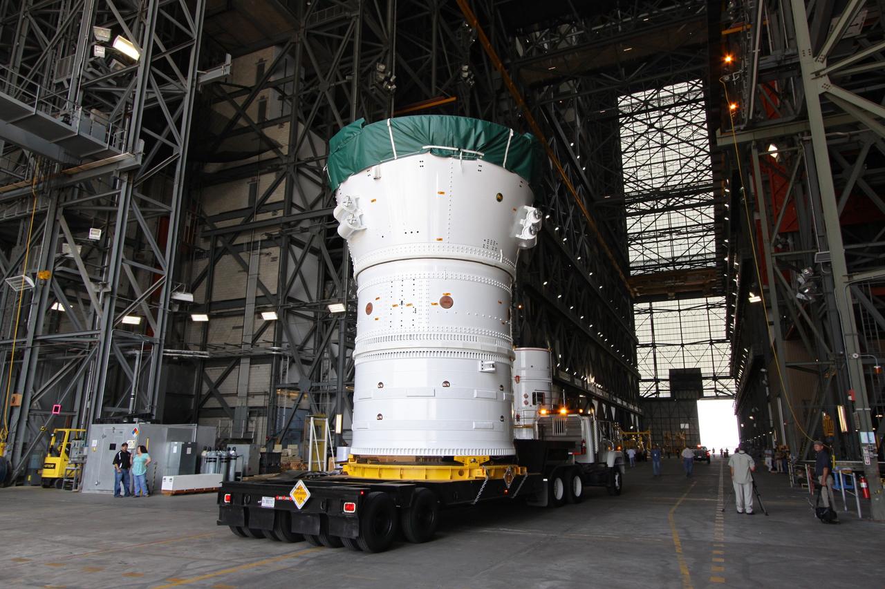
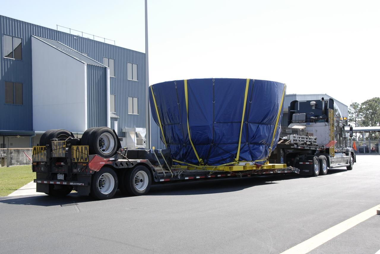
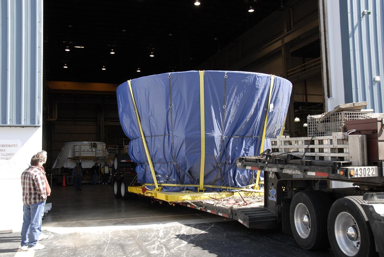
CAPE CANAVERAL, Fla. – At NASA's Kennedy Space Center in Florida, the Ares I-X forward assembly comprising the frustum, forward skirt extension and forward skirt moves into the transfer aisle of the Vehicle Assembly Building. The assembly will be placed in the VAB's High Bay 4 where it will undergo processing and stacking to the upper stage. Ares I-X is the flight test for the Ares I which will provide NASA an early opportunity to test and prove hardware, facilities and ground operations associated with Ares I, which is part of the Constellation Program to return men to the moon and beyond. Launch of the Ares I-X flight test is targeted for August 2009. Photo credit: NASA/Jack Pfaller
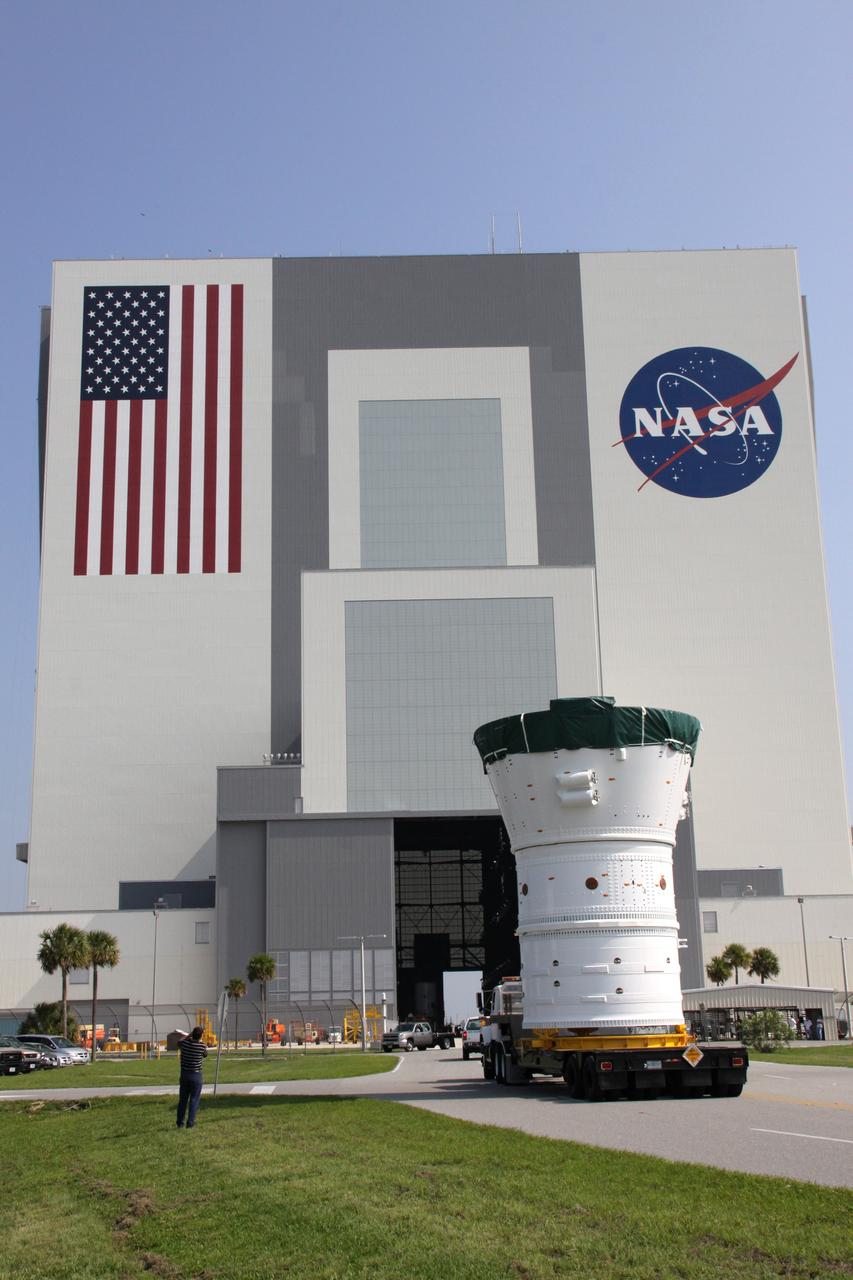
CAPE CANAVERAL, Fla. – At NASA's Kennedy Space Center in Florida, the Ares I-X forward assembly comprising the frustum, forward skirt extension and forward skirt heads for the Vehicle Assembly Building, in the background. In the VAB's High Bay 4, the forward assembly will undergo processing and stacking to the upper stage. Ares I-X is the flight test for the Ares I which will provide NASA an early opportunity to test and prove hardware, facilities and ground operations associated with Ares I, which is part of the Constellation Program to return men to the moon and beyond. Launch of the Ares I-X flight test is targeted for August 2009. Photo credit: NASA/Jack Pfaller
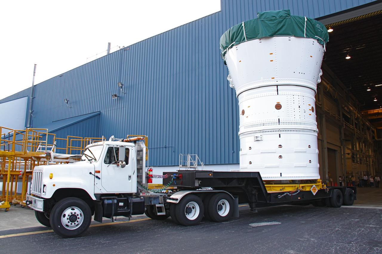
CAPE CANAVERAL, Fla. – At NASA's Kennedy Space Center in Florida, the Ares I-X forward assembly (comprising the frustum, forward skirt extension and forward skirt) moves out of the Assembly and Refurbishment Facility. It is being transferred to the Vehicle Assembly Building's High Bay 4 for processing and stacking to the upper stage. Ares I-X is the flight test for the Ares I which will provide NASA an early opportunity to test and prove hardware, facilities and ground operations associated with Ares I, which is part of the Constellation Program to return men to the moon and beyond. Launch of the Ares I-X flight test is targeted for August 2009. Photo credit: NASA/Jack Pfaller
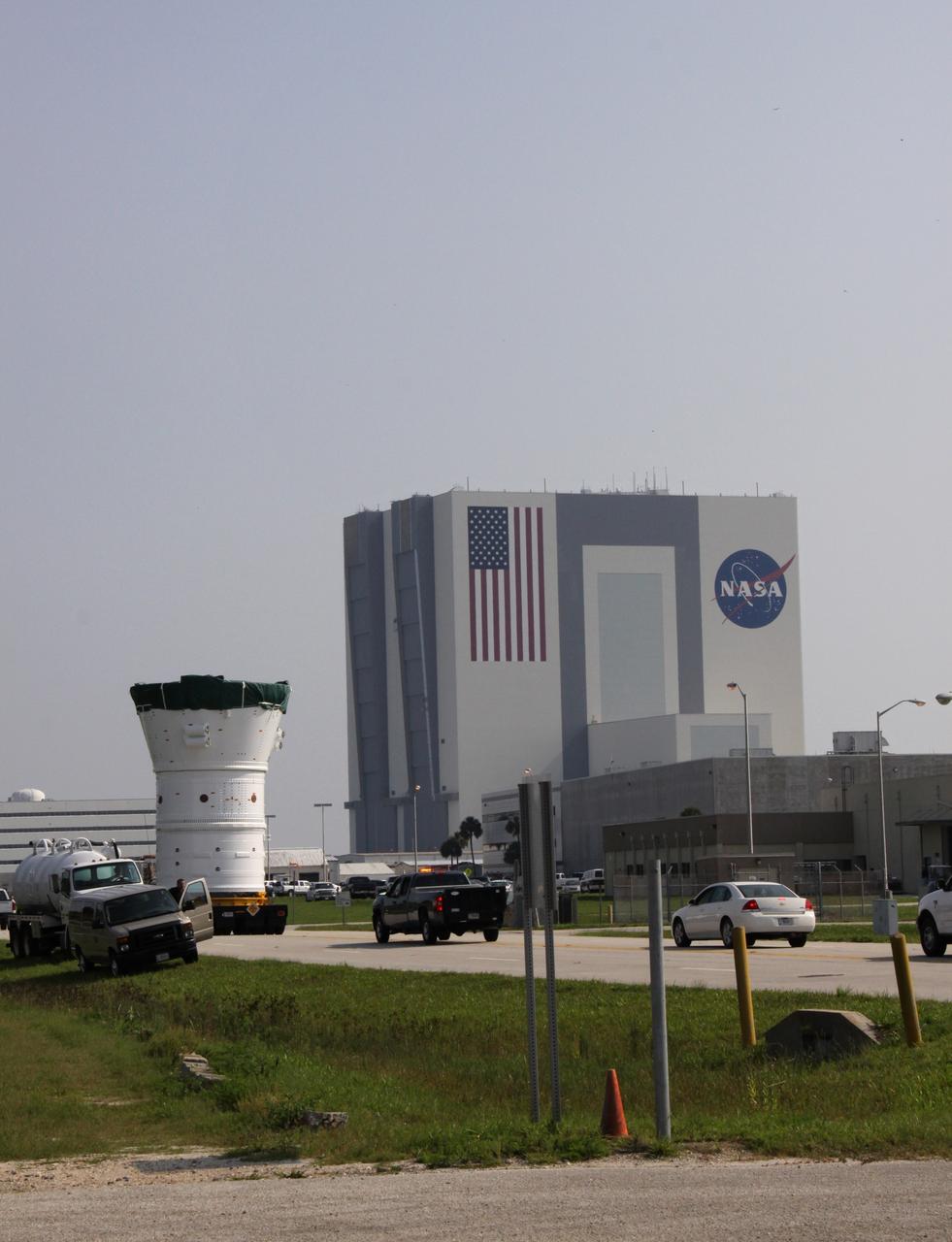
CAPE CANAVERAL, Fla. – At NASA's Kennedy Space Center in Florida, the Ares I-X forward assembly comprising the frustum, forward skirt extension and forward skirt , at left, moves toward the Vehicle Assembly Building, in the background. In the VAB's High Bay 4, the forward assembly will undergo processing and stacking to the upper stage. Ares I-X is the flight test for the Ares I which will provide NASA an early opportunity to test and prove hardware, facilities and ground operations associated with Ares I, which is part of the Constellation Program to return men to the moon and beyond. Launch of the Ares I-X flight test is targeted for August 2009. Photo credit: NASA/Jack Pfaller
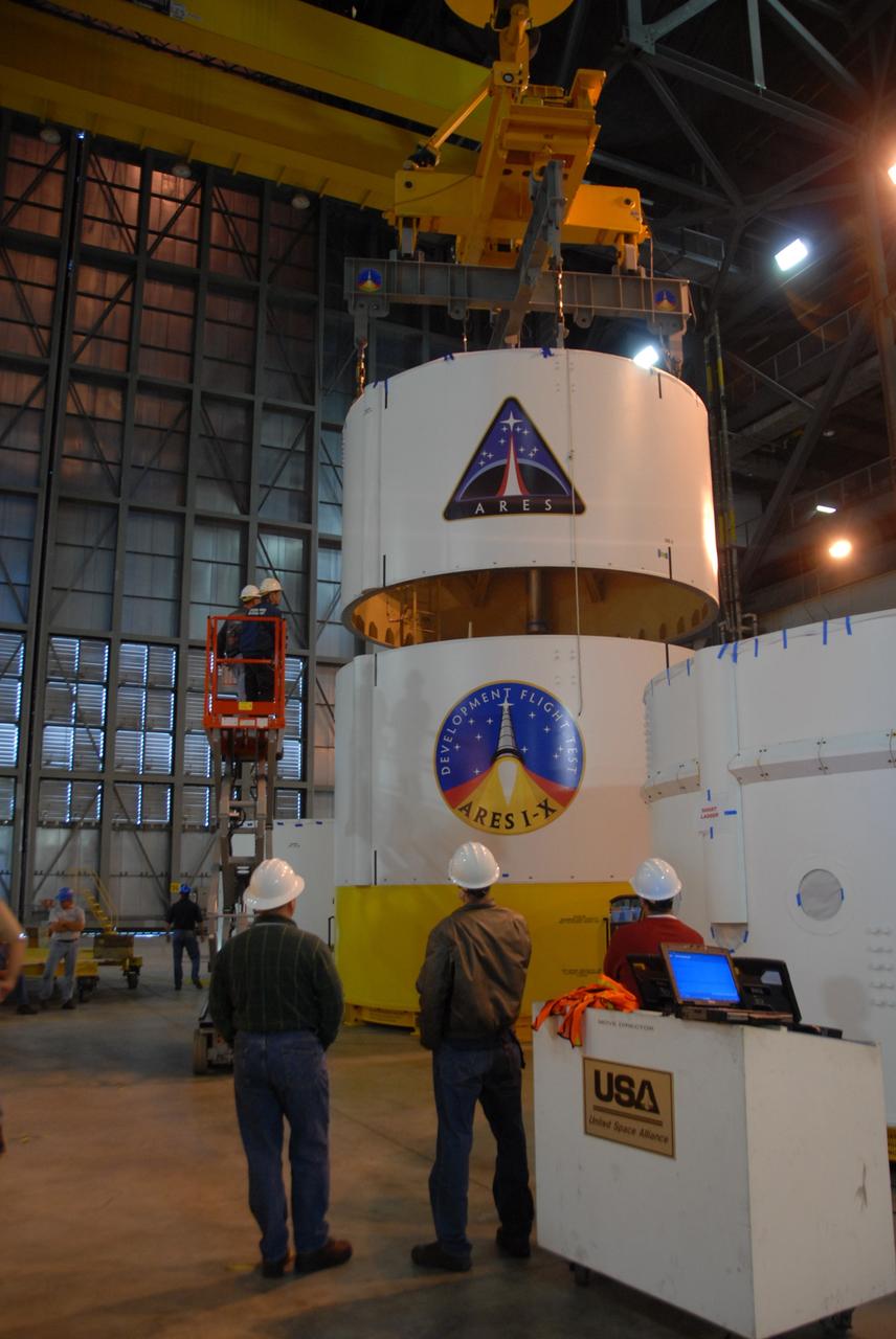
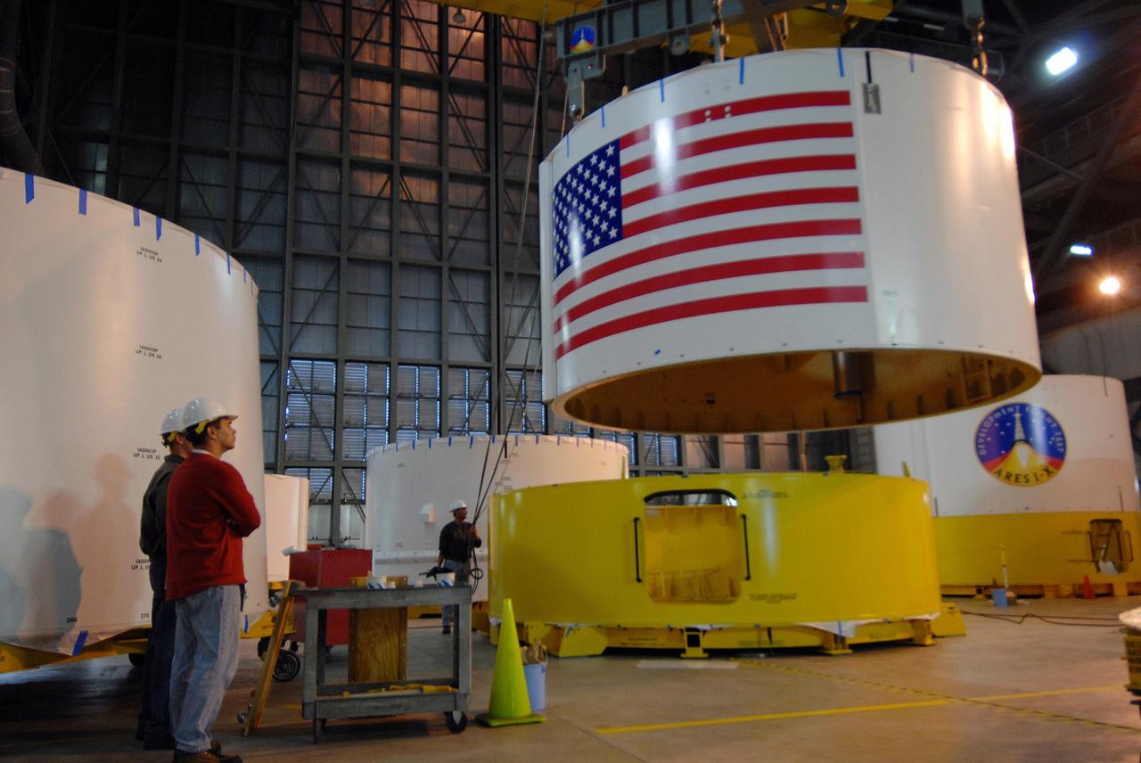
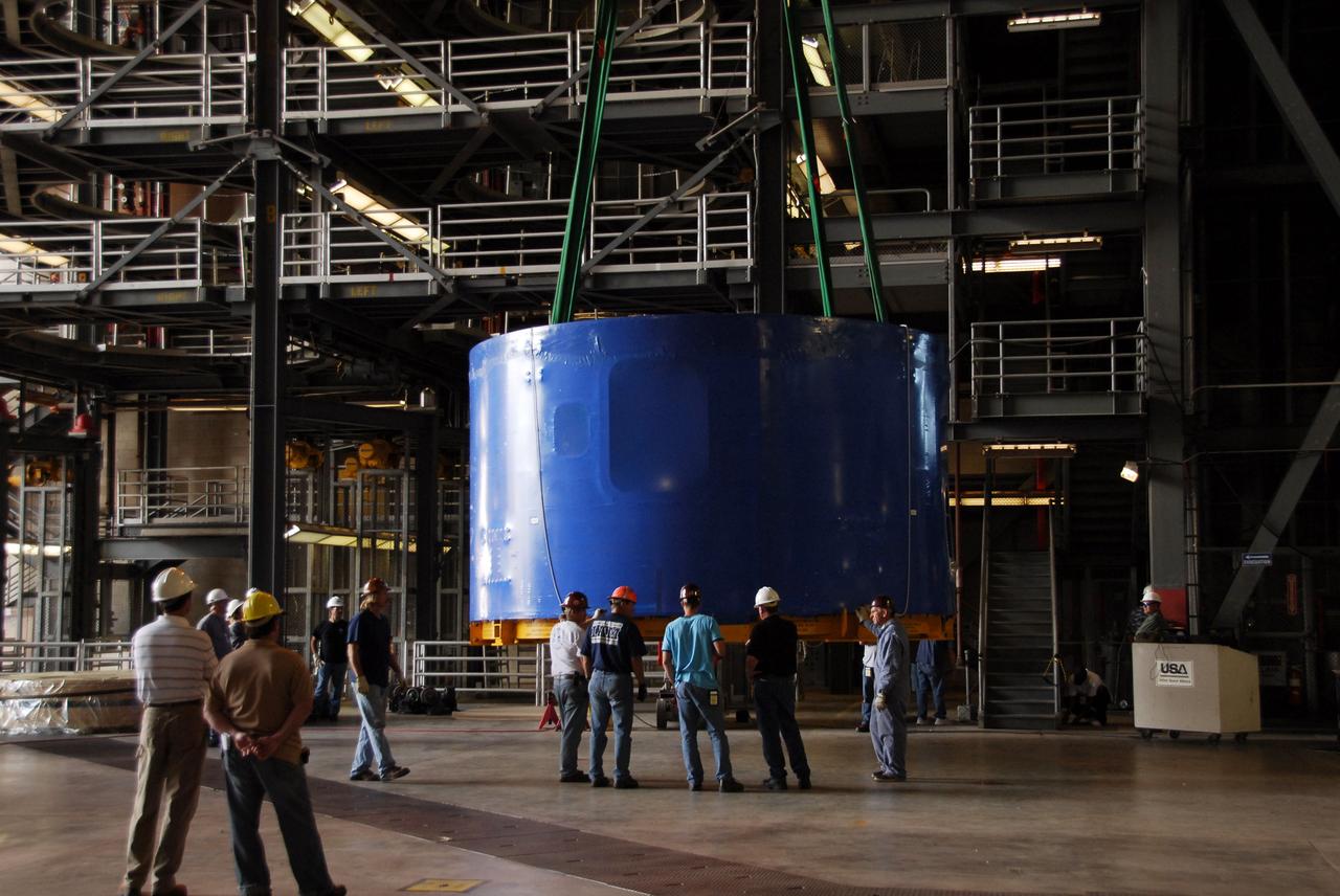
CAPE CANAVERAL, Fla. -- Inside the Vehicle Assembly Building's high bay 4 at NASA's Kennedy Space Center in Florida, Ares I-X upper stage simulator segment 3 is lowered onto segment 2. The upper stage simulator comprises 11 segments, each approximately 18 feet in diameter, that will be used in the test flight identified as Ares I-X in 2009. The test flight will provide NASA an early opportunity to test and prove hardware, facilities and ground operations associated with the Ares I crew launch vehicle. The data will ensure the entire vehicle system is safe and fully operational before astronauts begin traveling to orbit. The simulator segments will simulate the mass and the outer mold line and will be more than 100 feet of the total vehicle height of 327 feet. Photo credit: NASA/Jack Pfaller
CAPE CANAVERAL, Fla. -- Inside the Vehicle Assembly Building's high bay 4 at NASA's Kennedy Space Center in Florida, Ares I-X upper stage simulator segment 6 is lifted off the floor to be moved to a stand. The upper stage simulator comprises 11 segments, each approximately 18 feet in diameter, that will be used in the test flight identified as Ares I-X in 2009. The test flight will provide NASA an early opportunity to test and prove hardware, facilities and ground operations associated with the Ares I crew launch vehicle. The data will ensure the entire vehicle system is safe and fully operational before astronauts begin traveling to orbit. The simulator segments will simulate the mass and the outer mold line and will be more than 100 feet of the total vehicle height of 327 feet. Photo credit: NASA/Jack Pfaller
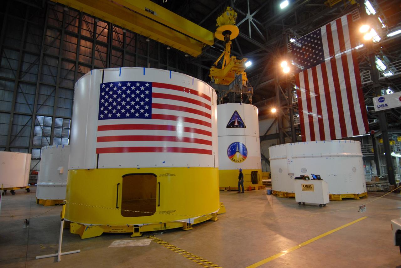
CAPE CANAVERAL, Fla. -- Inside the Vehicle Assembly Building's high bay 4 at NASA's Kennedy Space Center in Florida are the Ares I-X upper stage simulator segments. In front at left is segment 6. Next to and behind it are the mated segments 3 (on top) and 2. Other segments are on the floor around them. The upper stage simulator comprises 11 segments, each approximately 18 feet in diameter, that will be used in the test flight identified as Ares I-X in 2009. The test flight will provide NASA an early opportunity to test and prove hardware, facilities and ground operations associated with the Ares I crew launch vehicle. The data will ensure the entire vehicle system is safe and fully operational before astronauts begin traveling to orbit. The simulator segments will simulate the mass and the outer mold line and will be more than 100 feet of the total vehicle height of 327 feet. Photo credit: NASA/Jack Pfaller
CAPE CANAVERAL, Fla. -- Inside the Vehicle Assembly Building's high bay 4 at NASA's Kennedy Space Center in Florida, workers watch as Ares I-X upper stage simulator segment 3 is lowered onto segment 2. The upper stage simulator comprises 11 segments, each approximately 18 feet in diameter, that will be used in the test flight identified as Ares I-X in 2009. The test flight will provide NASA an early opportunity to test and prove hardware, facilities and ground operations associated with the Ares I crew launch vehicle. The data will ensure the entire vehicle system is safe and fully operational before astronauts begin traveling to orbit. The simulator segments will simulate the mass and the outer mold line and will be more than 100 feet of the total vehicle height of 327 feet. Photo credit: NASA/Jack Pfaller
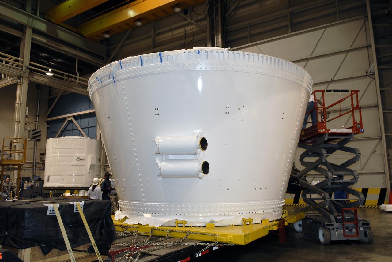
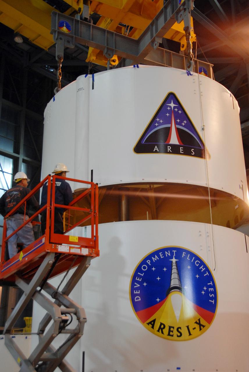
CAPE CANAVERAL, Fla. – In the Assembly and Refurbishment Facility of NASA's Kennedy Space Center, the last newly manufactured section of the Ares I-X test rocket, the frustum, is revealed after removal of the shipping covers. Resembling a giant funnel, the frustum's function is to transition the primary flight loads from the rocket's upper stage to the first stage. The frustum is located between the forward skirt extension and the upper stage of the Ares I-X. Weighing in at approximately 13,000 pounds, the 10-foot-long section is composed of two aluminum rings attached to a truncated conic section. The large diameter of the cone is 18 feet and the small diameter is 12 feet. The cone is 1.25 inches thick. The frustum will be integrated with the forward skirt and forward skirt extension, which already are in the Assembly and Refurbishment Facility. That will complete the forward assembly. The assembly then will be moved to the Vehicle Assembly Building for stacking operations, which are scheduled to begin in April. Manufactured by Major Tool and Machine Inc. in Indiana under a subcontract with Alliant Techsystems Inc., or ATK, the Ares I-X is targeted to launch in the summer of 2009. The flight will provide NASA with an early opportunity to test and prove hardware, facilities and ground operations associated with the Ares I launch vehicle. The flight test also will bring NASA a step closer to its exploration goals of sending humans to the moon and destinations beyond. Photo credit: NASA/Kim Shiflett
CAPE CANAVERAL, Fla. – The last newly manufactured section of the Ares I-X test rocket, the frustum, arrives at the Assembly and Refurbishment Facility of NASA's Kennedy Space Center. Resembling a giant funnel, the frustum's function is to transition the primary flight loads from the rocket's upper stage to the first stage. The frustum is located between the forward skirt extension and the upper stage of the Ares I-X. Weighing in at approximately 13,000 pounds, the 10-foot-long section is composed of two aluminum rings attached to a truncated conic section. The large diameter of the cone is 18 feet and the small diameter is 12 feet. The cone is 1.25 inches thick. The frustum will be integrated with the forward skirt and forward skirt extension, which already are in the Assembly and Refurbishment Facility. That will complete the forward assembly. The assembly then will be moved to the Vehicle Assembly Building for stacking operations, which are scheduled to begin in April. Manufactured by Major Tool and Machine Inc. in Indiana under a subcontract with Alliant Techsystems Inc., or ATK, the Ares I-X is targeted to launch in the summer of 2009. The flight will provide NASA with an early opportunity to test and prove hardware, facilities and ground operations associated with the Ares I launch vehicle. The flight test also will bring NASA a step closer to its exploration goals of sending humans to the moon and destinations beyond. Photo credit: NASA/Kim Shiflett
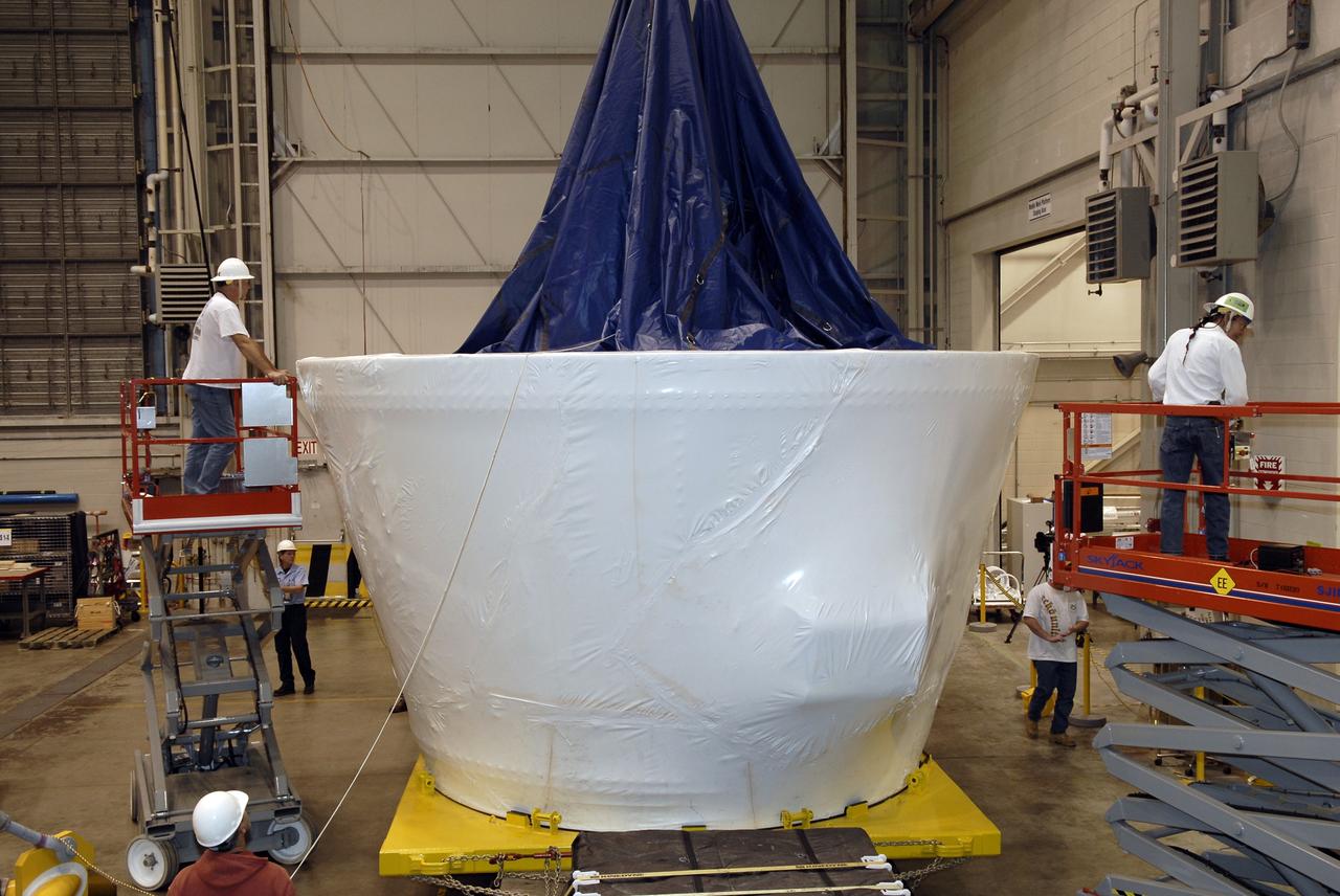
CAPE CANAVERAL, Fla. – In the Assembly and Refurbishment Facility of NASA's Kennedy Space Center, workers remove the cover from the frustum, the last newly manufactured section of the Ares I-X test rocket. Resembling a giant funnel, the frustum's function is to transition the primary flight loads from the rocket's upper stage to the first stage. The frustum is located between the forward skirt extension and the upper stage of the Ares I-X. Weighing in at approximately 13,000 pounds, the 10-foot-long section is composed of two aluminum rings attached to a truncated conic section. The large diameter of the cone is 18 feet and the small diameter is 12 feet. The cone is 1.25 inches thick. The frustum will be integrated with the forward skirt and forward skirt extension, which already are in the Assembly and Refurbishment Facility. That will complete the forward assembly. The assembly then will be moved to the Vehicle Assembly Building for stacking operations, which are scheduled to begin in April. Manufactured by Major Tool and Machine Inc. in Indiana under a subcontract with Alliant Techsystems Inc., or ATK, the Ares I-X is targeted to launch in the summer of 2009. The flight will provide NASA with an early opportunity to test and prove hardware, facilities and ground operations associated with the Ares I launch vehicle. The flight test also will bring NASA a step closer to its exploration goals of sending humans to the moon and destinations beyond. Photo credit: NASA/Kim Shiflett
CAPE CANAVERAL, Fla. – The last newly manufactured section of the Ares I-X test rocket, the frustum, is offloaded in the Assembly and Refurbishment Facility of NASA's Kennedy Space Center. Resembling a giant funnel, the frustum's function is to transition the primary flight loads from the rocket's upper stage to the first stage. The frustum is located between the forward skirt extension and the upper stage of the Ares I-X. Weighing in at approximately 13,000 pounds, the 10-foot-long section is composed of two aluminum rings attached to a truncated conic section. The large diameter of the cone is 18 feet and the small diameter is 12 feet. The cone is 1.25 inches thick. The frustum will be integrated with the forward skirt and forward skirt extension, which already are in the Assembly and Refurbishment Facility. That will complete the forward assembly. The assembly then will be moved to the Vehicle Assembly Building for stacking operations, which are scheduled to begin in April. Manufactured by Major Tool and Machine Inc. in Indiana under a subcontract with Alliant Techsystems Inc., or ATK, the Ares I-X is targeted to launch in the summer of 2009. The flight will provide NASA with an early opportunity to test and prove hardware, facilities and ground operations associated with the Ares I launch vehicle. The flight test also will bring NASA a step closer to its exploration goals of sending humans to the moon and destinations beyond. Photo credit: NASA/Kim Shiflett

CAPE CANAVERAL, Fla. – In the Assembly and Refurbishment Facility of NASA's Kennedy Space Center, workers remove the cover from the frustum, the last newly manufactured section of the Ares I-X test rocket. Resembling a giant funnel, the frustum's function is to transition the primary flight loads from the rocket's upper stage to the first stage. The frustum is located between the forward skirt extension and the upper stage of the Ares I-X. Weighing in at approximately 13,000 pounds, the 10-foot-long section is composed of two aluminum rings attached to a truncated conic section. The large diameter of the cone is 18 feet and the small diameter is 12 feet. The cone is 1.25 inches thick. The frustum will be integrated with the forward skirt and forward skirt extension, which already are in the Assembly and Refurbishment Facility. That will complete the forward assembly. The assembly then will be moved to the Vehicle Assembly Building for stacking operations, which are scheduled to begin in April. Manufactured by Major Tool and Machine Inc. in Indiana under a subcontract with Alliant Techsystems Inc., or ATK, the Ares I-X is targeted to launch in the summer of 2009. The flight will provide NASA with an early opportunity to test and prove hardware, facilities and ground operations associated with the Ares I launch vehicle. The flight test also will bring NASA a step closer to its exploration goals of sending humans to the moon and destinations beyond. Photo credit: NASA/Kim Shiflett
CAPE CANAVERAL, Fla. – At the Assembly and Refurbishment Facility at NASA's Kennedy Space Center in Florida, Robert Lightfoot, acting center director of NASA's Marshall Space Flight Center, speaks to employees who were involved in the processing of the Ares I-X forward assembly (comprising the frustum, forward skirt extension and forward skirt) . The forward assembly is being moved to the Vehicle Assembly Building's High Bay 4 for processing and stacking to the upper stage. Ares I-X is the flight test for the Ares I which will provide NASA an early opportunity to test and prove hardware, facilities and ground operations associated with Ares I, which is part of the Constellation Program to return men to the moon and beyond. Launch of the Ares I-X flight test is targeted for August 2009. Photo credit: NASA/Jack Pfaller
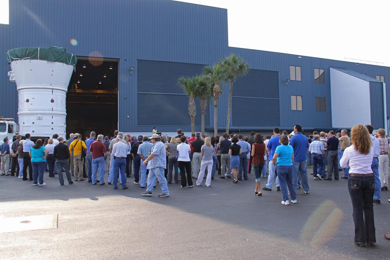
CAPE CANAVERAL, Fla. – At NASA's Kennedy Space Center in Florida, employees gather to watch the Ares I-X forward assembly (comprising the frustum, forward skirt extension and forward skirt) as it moves out of the Assembly and Refurbishment Facility. The assembly is being transferred to the Vehicle Assembly Building's High Bay 4 for processing and stacking to the upper stage. Ares I-X is the flight test for the Ares I which will provide NASA an early opportunity to test and prove hardware, facilities and ground operations associated with Ares I, which is part of the Constellation Program to return men to the moon and beyond. Launch of the Ares I-X flight test is targeted for August 2009. Photo credit: NASA/Jack Pfaller
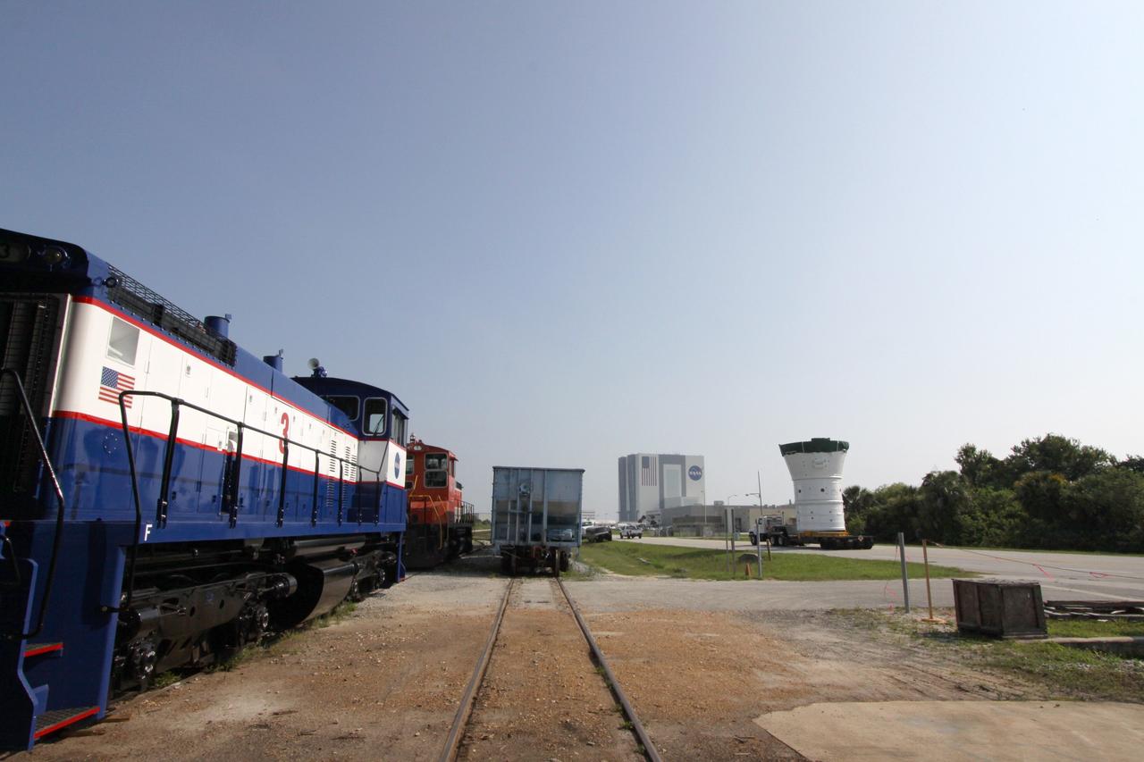
CAPE CANAVERAL, Fla. – At NASA's Kennedy Space Center in Florida, the Ares I-X forward assembly (comprising the frustum, forward skirt extension and forward skirt) moves alongside the NASA Railroad tracks as it heads for the Vehicle Assembly Building, in the background. In the VAB's High Bay 4, the forward assembly will undergo processing and stacking to the upper stage. Ares I-X is the flight test for the Ares I which will provide NASA an early opportunity to test and prove hardware, facilities and ground operations associated with Ares I, which is part of the Constellation Program to return men to the moon and beyond. Launch of the Ares I-X flight test is targeted for August 2009. Photo credit: NASA/Jack Pfaller
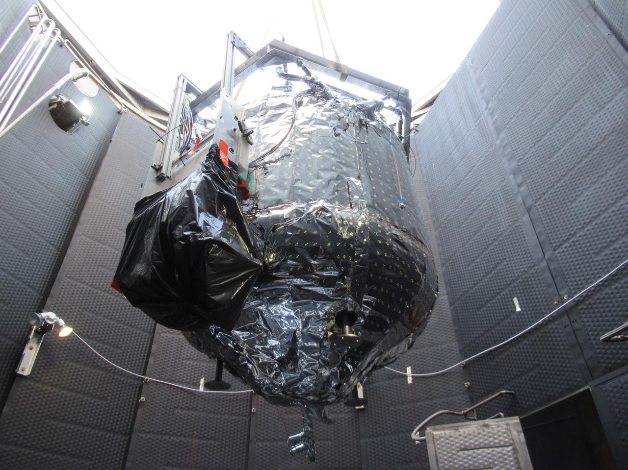
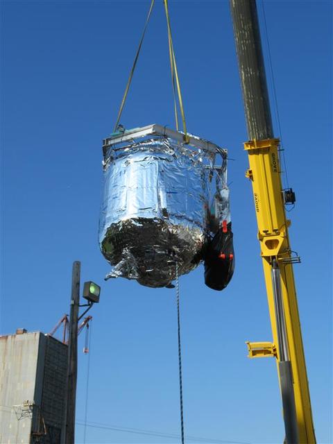
These photos show how teams at NASA’s Marshall Space Flight Center in Huntsville, Alabama, are testing an innovative approach to achieve zero boiloff storage of liquid hydrogen using two stages of active cooling, which could prevent the loss of valuable propellant during future long-duration spaceflight missions. Test teams installed the propellant tank in Test Stand 300 at NASA Marshall in early June, and the 90-day test campaign is scheduled to conclude in September. The tank is wrapped in a multi-layer insulation blanket that includes a thin aluminum heat shield fitted between layers. A second set of tubes, carrying helium at about minus 298 Fahrenheit, is integrated into the shield. This intermediate cooling layer intercepts and rejects incoming heat before it reaching the tank, easing the heat load on the tube-on-tank system. The Cryogenic Fluid Management Portfolio Project is a cross-agency team based at NASA Marshall and the agency’s Glenn Research Center in Cleveland. The cryogenic portfolio’s work is under NASA’s Technology Demonstration Missions Program, part of NASA’s Space Technology Mission Directorate, and is comprised of more than 20 individual technology development activities. For more information, contact NASA Marshall’s Office of Communications at 256-544-0034.

These photos show how teams at NASA’s Marshall Space Flight Center in Huntsville, Alabama, are testing an innovative approach to achieve zero boiloff storage of liquid hydrogen using two stages of active cooling, which could prevent the loss of valuable propellant during future long-duration spaceflight missions. Test teams installed the propellant tank in Test Stand 300 at NASA Marshall in early June, and the 90-day test campaign is scheduled to conclude in September. The tank is wrapped in a multi-layer insulation blanket that includes a thin aluminum heat shield fitted between layers. A second set of tubes, carrying helium at about minus 298 Fahrenheit, is integrated into the shield. This intermediate cooling layer intercepts and rejects incoming heat before it reaching the tank, easing the heat load on the tube-on-tank system. The Cryogenic Fluid Management Portfolio Project is a cross-agency team based at NASA Marshall and the agency’s Glenn Research Center in Cleveland. The cryogenic portfolio’s work is under NASA’s Technology Demonstration Missions Program, part of NASA’s Space Technology Mission Directorate, and is comprised of more than 20 individual technology development activities. For more information, contact NASA Marshall’s Office of Communications at 256-544-0034.
These photos show how teams at NASA’s Marshall Space Flight Center in Huntsville, Alabama, are testing an innovative approach to achieve zero boiloff storage of liquid hydrogen using two stages of active cooling, which could prevent the loss of valuable propellant during future long-duration spaceflight missions. Test teams installed the propellant tank in Test Stand 300 at NASA Marshall in early June, and the 90-day test campaign is scheduled to conclude in September. The tank is wrapped in a multi-layer insulation blanket that includes a thin aluminum heat shield fitted between layers. A second set of tubes, carrying helium at about minus 298 Fahrenheit, is integrated into the shield. This intermediate cooling layer intercepts and rejects incoming heat before it reaching the tank, easing the heat load on the tube-on-tank system. The Cryogenic Fluid Management Portfolio Project is a cross-agency team based at NASA Marshall and the agency’s Glenn Research Center in Cleveland. The cryogenic portfolio’s work is under NASA’s Technology Demonstration Missions Program, part of NASA’s Space Technology Mission Directorate, and is comprised of more than 20 individual technology development activities. For more information, contact NASA Marshall’s Office of Communications at 256-544-0034.
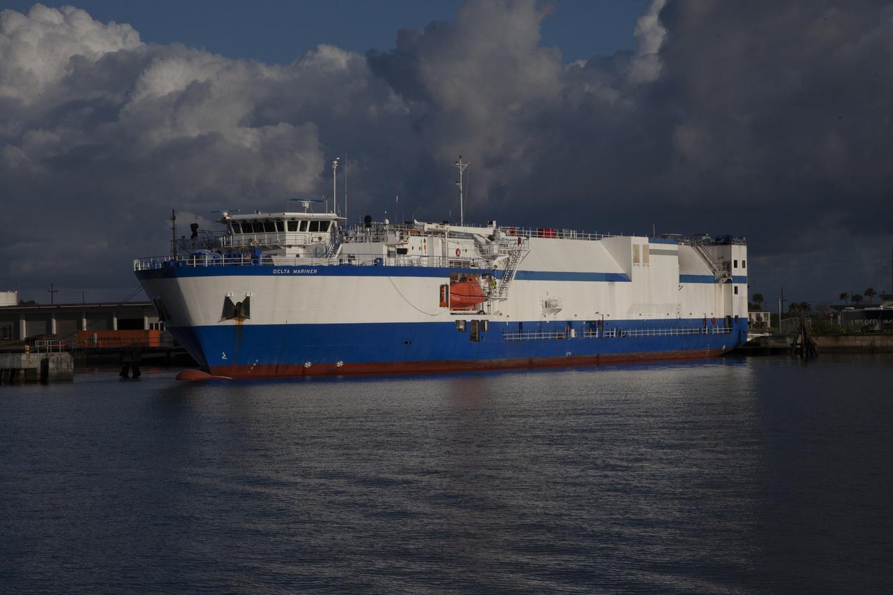
The United Launch Alliance (ULA) Mariner ship arrives at Port Canaveral in Florida carrying a two-engine Centaur upper stage for the upcoming uncrewed Orbital Flight Test of a Boeing CST-100 Starliner spacecraft. As part of NASA's Commercial Crew Program (CCP), the Starliner is part of the next generation of American spacecraft that will launch astronauts to the International Space Station. Starliner will launch early next year atop a ULA Atlas V rocket with the Centaur upper stage from Space Launch Complex 41 at Cape Canaveral Air Force Statin. NASA’s Commercial Crew Program will return human spaceflight launches to U.S. soil, providing safe, reliable and cost-effective access to low-Earth orbit on systems that meet our safety and mission requirements.
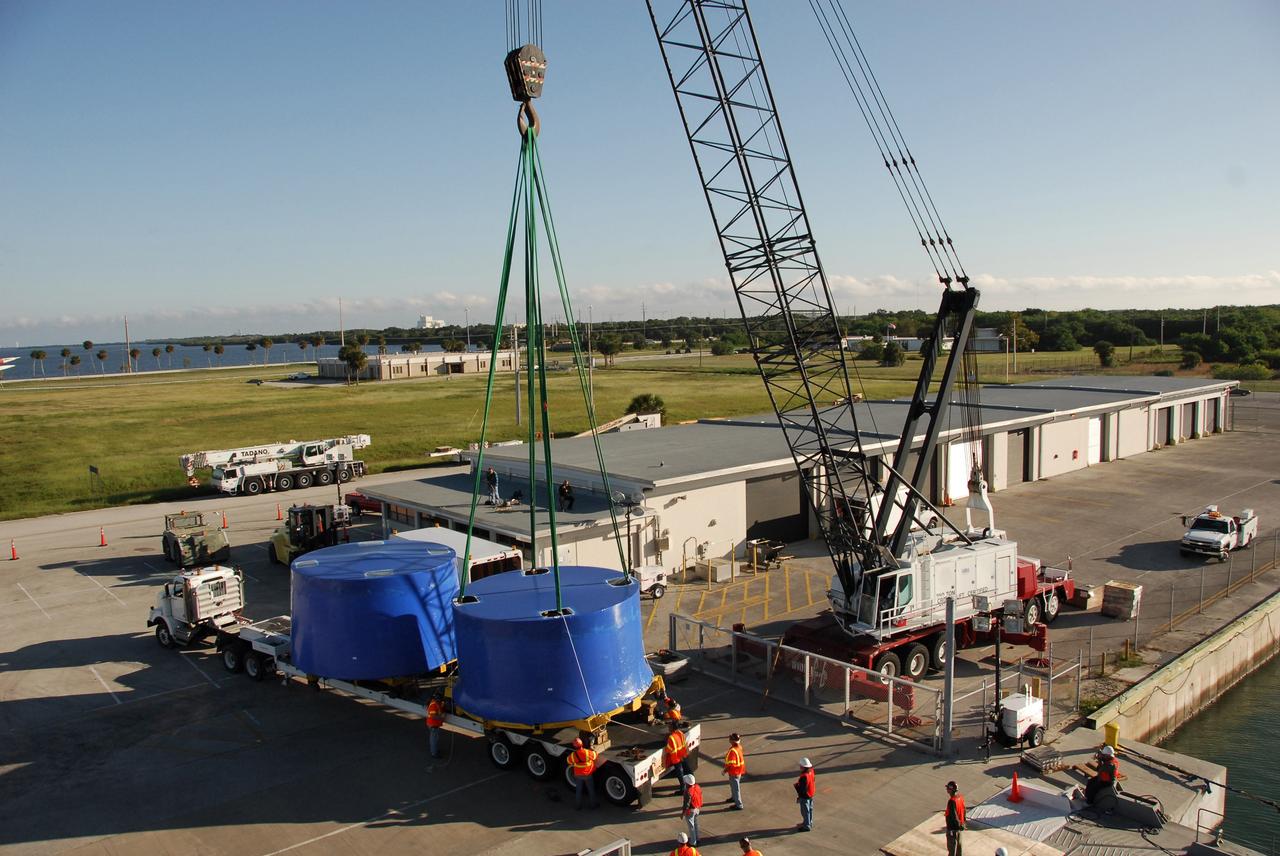
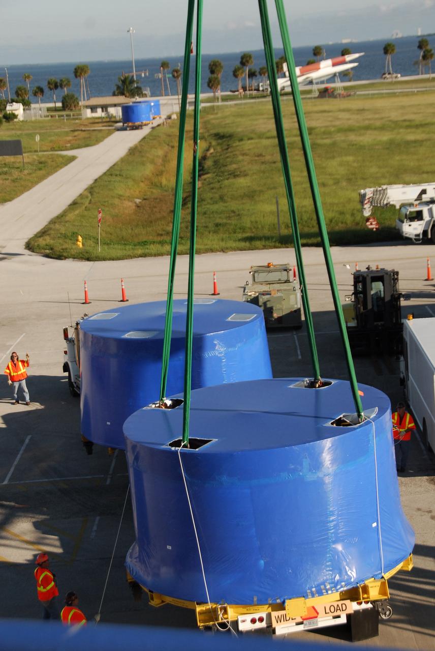
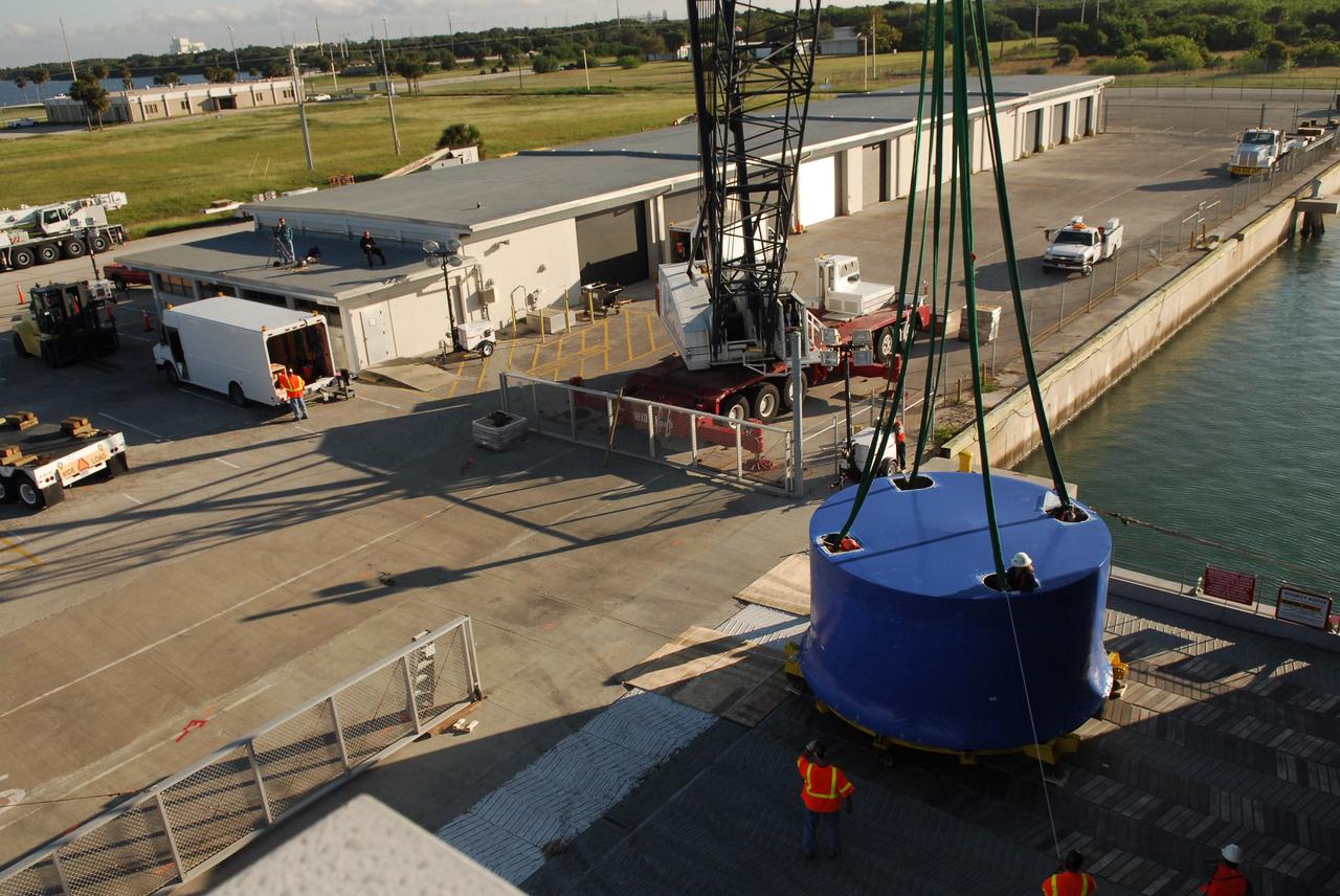
CAPE CANAVERAL, Fla. – A crane lifts and transfers Ares I-X upper stage simulator segments from the Delta Mariner at Port Canaveral, Fla., onto a flatbed truck. They will be transported to the Vehicle Assembly Building's high bay 4 at NASA's Kennedy Space Center in Florida. The upper stage simulator will be used in the test flight identified as Ares I-X in 2009. The Ares I-X test flight will provide NASA an early opportunity to test and prove hardware, facilities and ground operations associated with the Ares I crew launch vehicle. It also will allow NASA to gather critical data during ascent of the integrated Orion crew exploration vehicle and the Ares I rocket. The data will ensure the entire vehicle system is safe and fully operational before astronauts begin traveling to orbit. The simulator segments will simulate the mass and the outer mold line and will be more than 100 feet of the total vehicle height of 327 feet. The simulator comprises 11 segments that are approximately 18 feet in diameter. Most of the segments will be approximately 10 feet high, ranging in weight from 18,000 to 60,000 pounds, for a total of approximately 450,000 pounds. Photo credit: NASA/Cory Huston
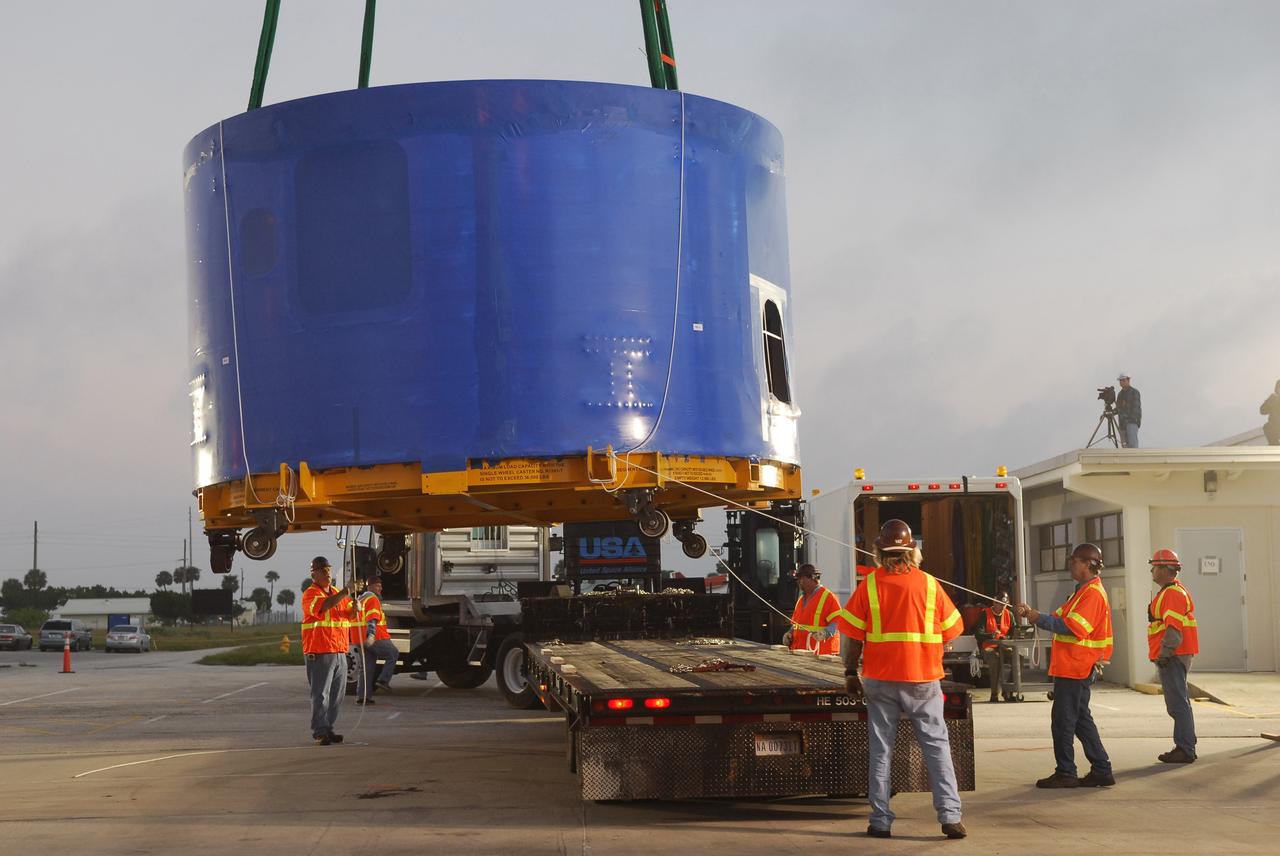
CAPE CANAVERAL, Fla. – A crane lifts and transfers an Ares I-X upper stage simulator segment from the Delta Mariner at Port Canaveral, Fla., onto a flatbed truck. They will be transported to the Vehicle Assembly Building's high bay 4 at NASA's Kennedy Space Center in Florida. The upper stage simulator will be used in the test flight identified as Ares I-X in 2009. The Ares I-X test flight will provide NASA an early opportunity to test and prove hardware, facilities and ground operations associated with the Ares I crew launch vehicle. It also will allow NASA to gather critical data during ascent of the integrated Orion crew exploration vehicle and the Ares I rocket. The data will ensure the entire vehicle system is safe and fully operational before astronauts begin traveling to orbit. The simulator segments will simulate the mass and the outer mold line and will be more than 100 feet of the total vehicle height of 327 feet. The simulator comprises 11 segments that are approximately 18 feet in diameter. Most of the segments will be approximately 10 feet high, ranging in weight from 18,000 to 60,000 pounds, for a total of approximately 450,000 pounds. Photo credit: NASA/Cory Huston
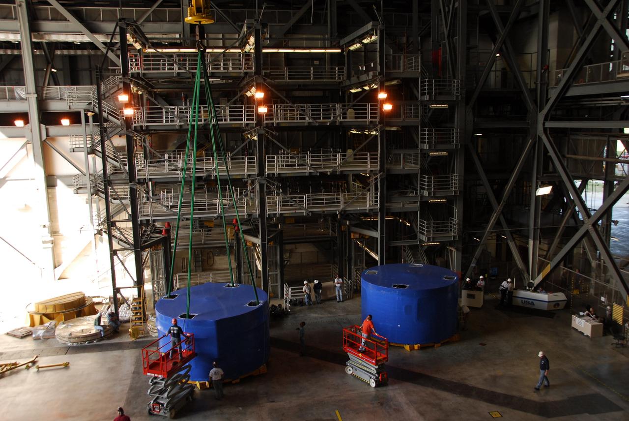
CAPE CANAVERAL, Fla. – Inside the Vehicle Assembly Building's high bay 4 at NASA's Kennedy Space Center in Florida, two of the Ares I-X upper stage simulator segments are offloaded from its transporter and placed on the floor. The segments arrived Nov. 4 at Port Canaveral, Fla., aboard the Delta Mariner. The upper stage simulators will be used in the test flight identified as Ares I-X in 2009. The Ares I-X test flight will provide NASA an early opportunity to test and prove hardware, facilities and ground operations associated with the Ares I crew launch vehicle. It also will allow NASA to gather critical data during ascent of the integrated Orion crew exploration vehicle and the Ares I rocket. The data will ensure the entire vehicle system is safe and fully operational before astronauts begin traveling to orbit. The simulator segments will simulate the mass and the outer mold line and will be more than 100 feet of the total vehicle height of 327 feet. The simulator comprises 11 segments that are approximately 18 feet in diameter. Most of the segments will be approximately 10 feet high, ranging in weight from 18,000 to 60,000 pounds, for a total of approximately 450,000 pounds. Photo credit: NASA/Cory Huston
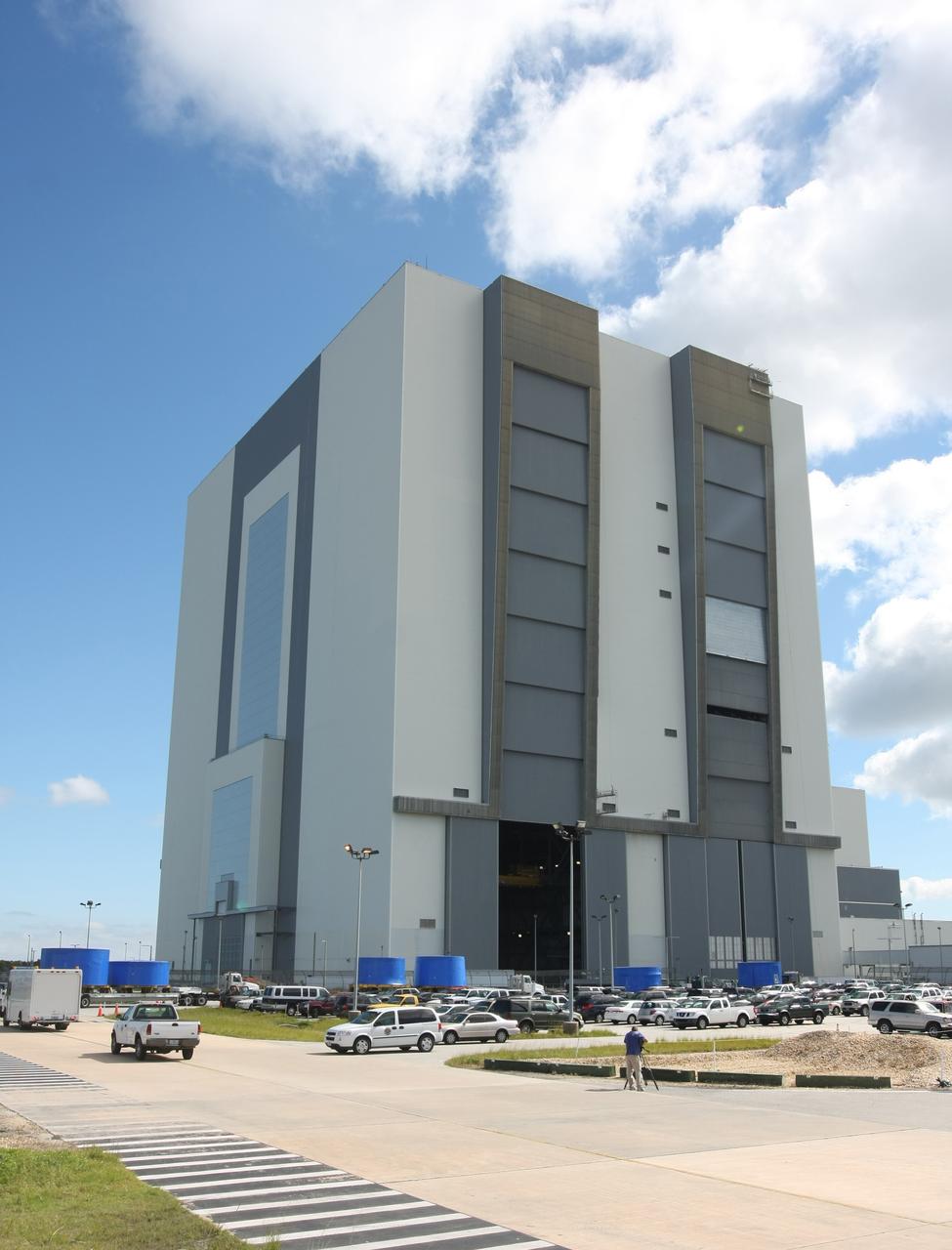
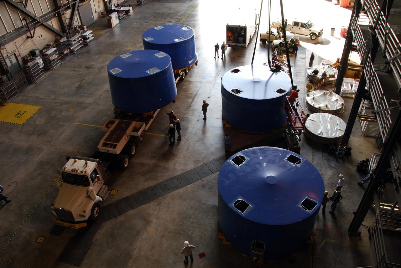
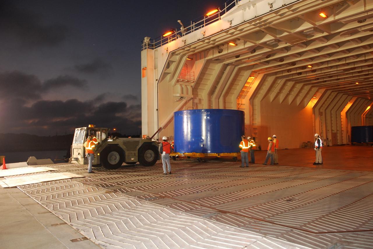
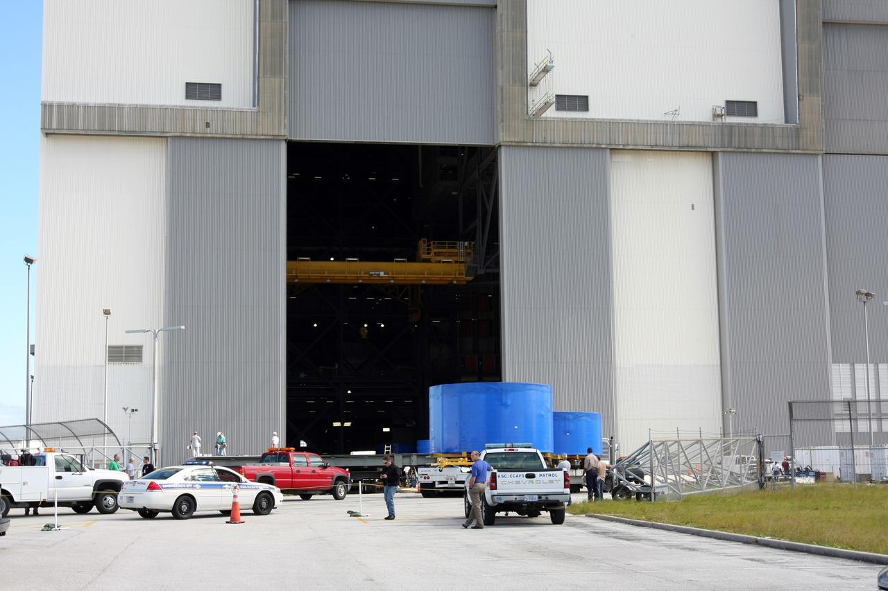
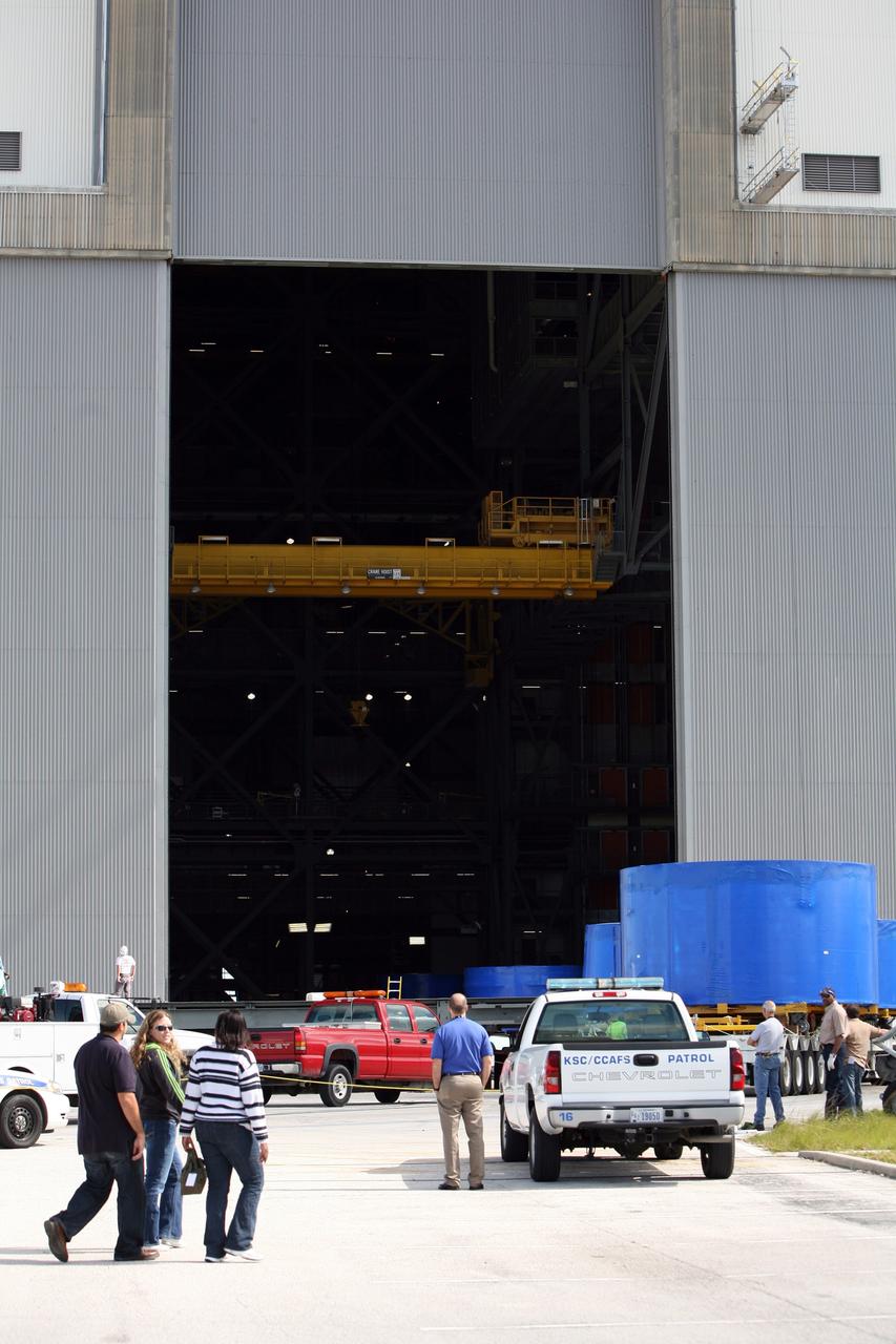
CAPE CANAVERAL, Fla. – Trucks carrying the blue Ares I-X upper stage simulator segments are lined up outside the Vehicle Assembly Building's high bay 4 at NASA's Kennedy Space Center in Florida. The segments will be offloaded inside bay 4. The upper stage simulators will be used in the test flight identified as Ares I-X in 2009. The Ares I-X test flight will provide NASA an early opportunity to test and prove hardware, facilities and ground operations associated with the Ares I crew launch vehicle. It also will allow NASA to gather critical data during ascent of the integrated Orion crew exploration vehicle and the Ares I rocket. The data will ensure the entire vehicle system is safe and fully operational before astronauts begin traveling to orbit. The simulator segments will simulate the mass and the outer mold line and will be more than 100 feet of the total vehicle height of 327 feet. The simulator comprises 11 segments that are approximately 18 feet in diameter. Most of the segments will be approximately 10 feet high, ranging in weight from 18,000 to 60,000 pounds, for a total of approximately 450,000 pounds. Photo credit: NASA/Cory Huston

CAPE CANAVERAL, Fla. – Trucks head into the Vehicle Assembly Building's high bay 4 at NASA's Kennedy Space Center in Florida. They carry Ares I-X upper stage simulator segments that arrived Nov. 4 at Port Canaveral, Fla., aboard the Delta Mariner. The upper stage simulators will be used in the test flight identified as Ares I-X in 2009. The Ares I-X test flight will provide NASA an early opportunity to test and prove hardware, facilities and ground operations associated with the Ares I crew launch vehicle. It also will allow NASA to gather critical data during ascent of the integrated Orion crew exploration vehicle and the Ares I rocket. The data will ensure the entire vehicle system is safe and fully operational before astronauts begin traveling to orbit. The simulator segments will simulate the mass and the outer mold line and will be more than 100 feet of the total vehicle height of 327 feet. The simulator comprises 11 segments that are approximately 18 feet in diameter. Most of the segments will be approximately 10 feet high, ranging in weight from 18,000 to 60,000 pounds, for a total of approximately 450,000 pounds. Photo credit: NASA/Cory Huston
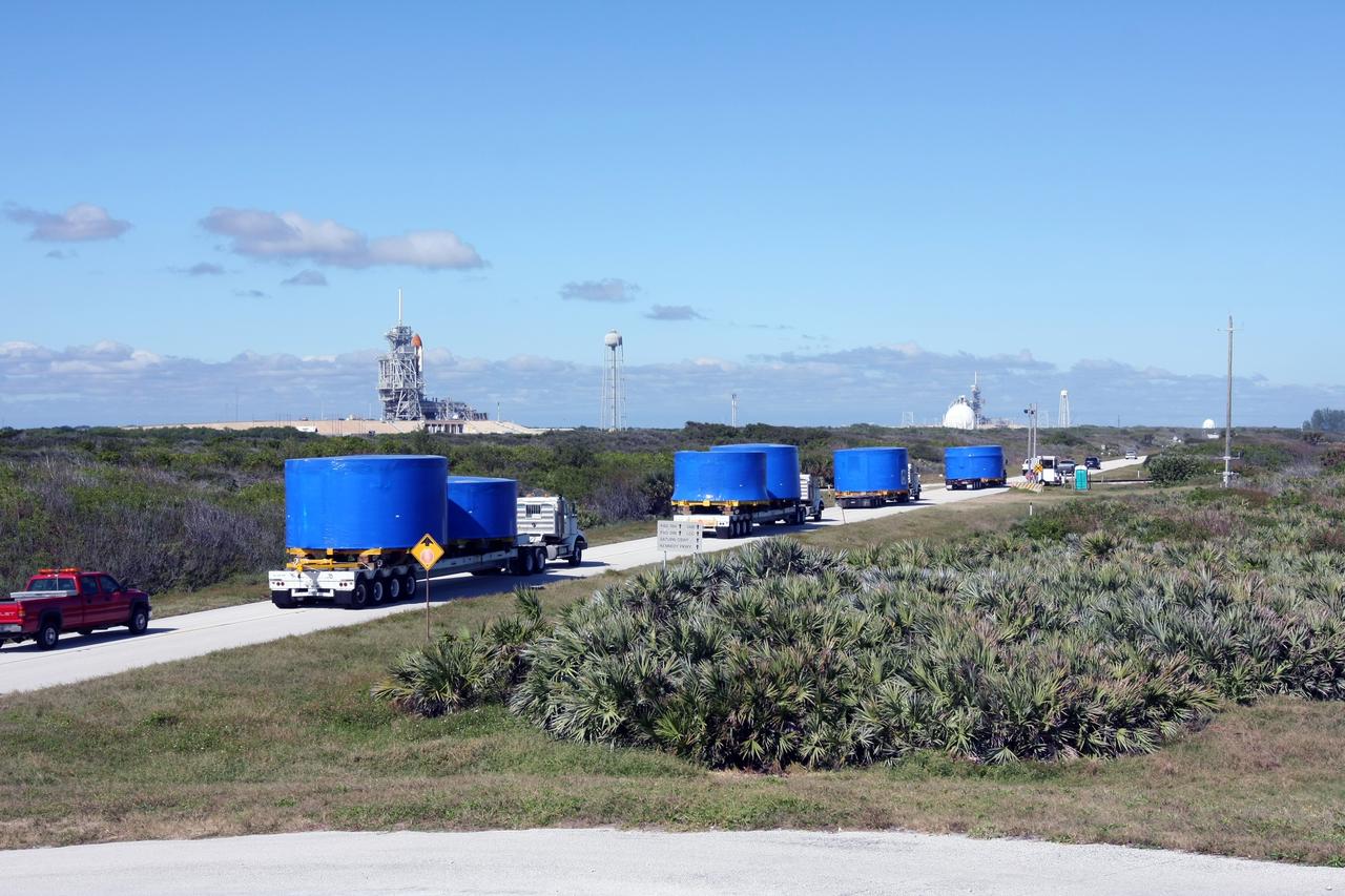
CAPE CANAVERAL, Fla. – A convoy of trucks passes a launch pad as it makes the journey from Port Canaveral, Fla., to the Vehicle Assembly Building's high bay 4 at NASA's Kennedy Space Center in Florida. The trucks carry Ares I-X upper stage simulator segments. The upper stage simulators will be used in the test flight identified as Ares I-X in 2009. The Ares I-X test flight will provide NASA an early opportunity to test and prove hardware, facilities and ground operations associated with the Ares I crew launch vehicle. It also will allow NASA to gather critical data during ascent of the integrated Orion crew exploration vehicle and the Ares I rocket. The data will ensure the entire vehicle system is safe and fully operational before astronauts begin traveling to orbit. The simulator segments will simulate the mass and the outer mold line and will be more than 100 feet of the total vehicle height of 327 feet. The simulator comprises 11 segments that are approximately 18 feet in diameter. Most of the segments will be approximately 10 feet high, ranging in weight from 18,000 to 60,000 pounds, for a total of approximately 450,000 pounds. Photo credit: NASA/Cory Huston
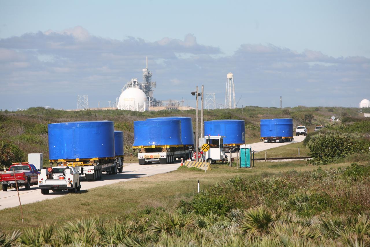
CAPE CANAVERAL, Fla. – A convoy of trucks passes a launch pad as it makes the journey from Port Canaveral, Fla., to the Vehicle Assembly Building's high bay 4 at NASA's Kennedy Space Center in Florida. The trucks carry Ares I-X upper stage simulator segments. The upper stage simulators will be used in the test flight identified as Ares I-X in 2009. The Ares I-X test flight will provide NASA an early opportunity to test and prove hardware, facilities and ground operations associated with the Ares I crew launch vehicle. It also will allow NASA to gather critical data during ascent of the integrated Orion crew exploration vehicle and the Ares I rocket. The data will ensure the entire vehicle system is safe and fully operational before astronauts begin traveling to orbit. The simulator segments will simulate the mass and the outer mold line and will be more than 100 feet of the total vehicle height of 327 feet. The simulator comprises 11 segments that are approximately 18 feet in diameter. Most of the segments will be approximately 10 feet high, ranging in weight from 18,000 to 60,000 pounds, for a total of approximately 450,000 pounds. Photo credit: NASA/Cory Huston
CAPE CANAVERAL, Fla. – Inside the Vehicle Assembly Building's high bay 4 at NASA's Kennedy Space Center in Florida, Ares I-X upper stage simulator segments are being offloaded onto the floor. The segments arrived Nov. 4 at Port Canaveral, Fla., aboard the Delta Mariner. The upper simulator segments are moved inside where they will be offloaded. The upper stage simulators will be used in the test flight identified as Ares I-X in 2009. The Ares I-X test flight will provide NASA an early opportunity to test and prove hardware, facilities and ground operations associated with the Ares I crew launch vehicle. It also will allow NASA to gather critical data during ascent of the integrated Orion crew exploration vehicle and the Ares I rocket. The data will ensure the entire vehicle system is safe and fully operational before astronauts begin traveling to orbit. The simulator segments will simulate the mass and the outer mold line and will be more than 100 feet of the total vehicle height of 327 feet. The simulator comprises 11 segments that are approximately 18 feet in diameter. Most of the segments will be approximately 10 feet high, ranging in weight from 18,000 to 60,000 pounds, for a total of approximately 450,000 pounds. Photo credit: NASA/Cory Huston
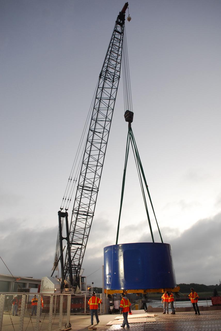
CAPE CANAVERAL, Fla. – A crane lifts and transfers an Ares I-X upper stage simulator segment from the Delta Mariner at Port Canaveral, Fla., onto a flatbed truck. They will be transported to the Vehicle Assembly Building's high bay 4 at NASA's Kennedy Space Center in Florida. The upper stage simulator will be used in the test flight identified as Ares I-X in 2009. The Ares I-X test flight will provide NASA an early opportunity to test and prove hardware, facilities and ground operations associated with the Ares I crew launch vehicle. It also will allow NASA to gather critical data during ascent of the integrated Orion crew exploration vehicle and the Ares I rocket. The data will ensure the entire vehicle system is safe and fully operational before astronauts begin traveling to orbit. The simulator segments will simulate the mass and the outer mold line and will be more than 100 feet of the total vehicle height of 327 feet. The simulator comprises 11 segments that are approximately 18 feet in diameter. Most of the segments will be approximately 10 feet high, ranging in weight from 18,000 to 60,000 pounds, for a total of approximately 450,000 pounds. Photo credit: NASA/Cory Huston
CAPE CANAVERAL, Fla. – At Port Canaveral, Fla., one of the Ares I-X upper stage simulator segments is offloaded from the Delta Mariner. The segment will be placed on a flatbed truck for transportation to the Vehicle Assembly Building's high bay 4 at NASA's Kennedy Space Center in Florida. The upper stage simulator will be used in the test flight identified as Ares I-X in 2009. The Ares I-X test flight will provide NASA an early opportunity to test and prove hardware, facilities and ground operations associated with the Ares I crew launch vehicle. It also will allow NASA to gather critical data during ascent of the integrated Orion crew exploration vehicle and the Ares I rocket. The data will ensure the entire vehicle system is safe and fully operational before astronauts begin traveling to orbit. The simulator segments will simulate the mass and the outer mold line and will be more than 100 feet of the total vehicle height of 327 feet. The simulator comprises 11 segments that are approximately 18 feet in diameter. Most of the segments will be approximately 10 feet high, ranging in weight from 18,000 to 60,000 pounds, for a total of approximately 450,000 pounds. Photo credit: NASA/Cory Huston
CAPE CANAVERAL, Fla. – At Port Canaveral, Fla., the Ares I-X upper stage simulator segments are being offloaded from the Delta Mariner. The segments will be placed on a flatbed truck for transportation to the Vehicle Assembly Building's high bay 4 at NASA's Kennedy Space Center in Florida. The upper stage simulator will be used in the test flight identified as Ares I-X in 2009. The Ares I-X test flight will provide NASA an early opportunity to test and prove hardware, facilities and ground operations associated with the Ares I crew launch vehicle. It also will allow NASA to gather critical data during ascent of the integrated Orion crew exploration vehicle and the Ares I rocket. The data will ensure the entire vehicle system is safe and fully operational before astronauts begin traveling to orbit. The simulator segments will simulate the mass and the outer mold line and will be more than 100 feet of the total vehicle height of 327 feet. The simulator comprises 11 segments that are approximately 18 feet in diameter. Most of the segments will be approximately 10 feet high, ranging in weight from 18,000 to 60,000 pounds, for a total of approximately 450,000 pounds. Photo credit: NASA/Cory Huston
CAPE CANAVERAL, Fla. – A crane lifts and transfers Ares I-X upper stage simulator segments from the Delta Mariner at Port Canaveral, Fla., onto a flatbed truck. They will be transported to the Vehicle Assembly Building's high bay 4 at NASA's Kennedy Space Center in Florida. The upper stage simulator will be used in the test flight identified as Ares I-X in 2009. The Ares I-X test flight will provide NASA an early opportunity to test and prove hardware, facilities and ground operations associated with the Ares I crew launch vehicle. It also will allow NASA to gather critical data during ascent of the integrated Orion crew exploration vehicle and the Ares I rocket. The data will ensure the entire vehicle system is safe and fully operational before astronauts begin traveling to orbit. The simulator segments will simulate the mass and the outer mold line and will be more than 100 feet of the total vehicle height of 327 feet. The simulator comprises 11 segments that are approximately 18 feet in diameter. Most of the segments will be approximately 10 feet high, ranging in weight from 18,000 to 60,000 pounds, for a total of approximately 450,000 pounds. Photo credit: NASA/Cory Huston
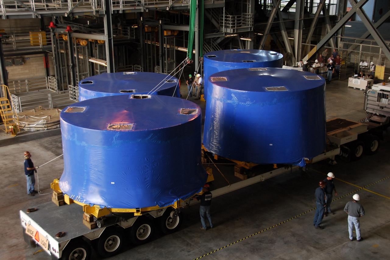
CAPE CANAVERAL, Fla. – Inside the Vehicle Assembly Building's high bay 4 at NASA's Kennedy Space Center in Florida, Ares I-X upper stage simulator segments are being offloaded onto the floor. The segments arrived Nov. 4 at Port Canaveral, Fla., aboard the Delta Mariner. The upper simulator segments are moved inside where they will be offloaded. The upper stage simulators will be used in the test flight identified as Ares I-X in 2009. The Ares I-X test flight will provide NASA an early opportunity to test and prove hardware, facilities and ground operations associated with the Ares I crew launch vehicle. It also will allow NASA to gather critical data during ascent of the integrated Orion crew exploration vehicle and the Ares I rocket. The data will ensure the entire vehicle system is safe and fully operational before astronauts begin traveling to orbit. The simulator segments will simulate the mass and the outer mold line and will be more than 100 feet of the total vehicle height of 327 feet. The simulator comprises 11 segments that are approximately 18 feet in diameter. Most of the segments will be approximately 10 feet high, ranging in weight from 18,000 to 60,000 pounds, for a total of approximately 450,000 pounds. Photo credit: NASA/Cory Huston
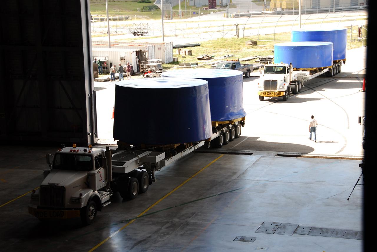
CAPE CANAVERAL, Fla. – Trucks pull into the Vehicle Assembly Building's high bay 4 at NASA's Kennedy Space Center in Florida. They carry Ares I-X upper stage simulator segments that arrived Nov. 4 at Port Canaveral, Fla., aboard the Delta Mariner. The upper stage simulators will be used in the test flight identified as Ares I-X in 2009. The Ares I-X test flight will provide NASA an early opportunity to test and prove hardware, facilities and ground operations associated with the Ares I crew launch vehicle. It also will allow NASA to gather critical data during ascent of the integrated Orion crew exploration vehicle and the Ares I rocket. The data will ensure the entire vehicle system is safe and fully operational before astronauts begin traveling to orbit. The simulator segments will simulate the mass and the outer mold line and will be more than 100 feet of the total vehicle height of 327 feet. The simulator comprises 11 segments that are approximately 18 feet in diameter. Most of the segments will be approximately 10 feet high, ranging in weight from 18,000 to 60,000 pounds, for a total of approximately 450,000 pounds. Photo credit: NASA/Cory Huston
CAPE CANAVERAL, Fla. – Inside the Vehicle Assembly Building's high bay 4 at NASA's Kennedy Space Center in Florida, one of the Ares I-X upper stage simulator segments is offloaded from its transporter and placed on the floor. The segments arrived Nov. 4 at Port Canaveral, Fla., aboard the Delta Mariner. The upper stage simulators will be used in the test flight identified as Ares I-X in 2009. The Ares I-X test flight will provide NASA an early opportunity to test and prove hardware, facilities and ground operations associated with the Ares I crew launch vehicle. It also will allow NASA to gather critical data during ascent of the integrated Orion crew exploration vehicle and the Ares I rocket. The data will ensure the entire vehicle system is safe and fully operational before astronauts begin traveling to orbit. The simulator segments will simulate the mass and the outer mold line and will be more than 100 feet of the total vehicle height of 327 feet. The simulator comprises 11 segments that are approximately 18 feet in diameter. Most of the segments will be approximately 10 feet high, ranging in weight from 18,000 to 60,000 pounds, for a total of approximately 450,000 pounds. Photo credit: NASA/Cory Huston
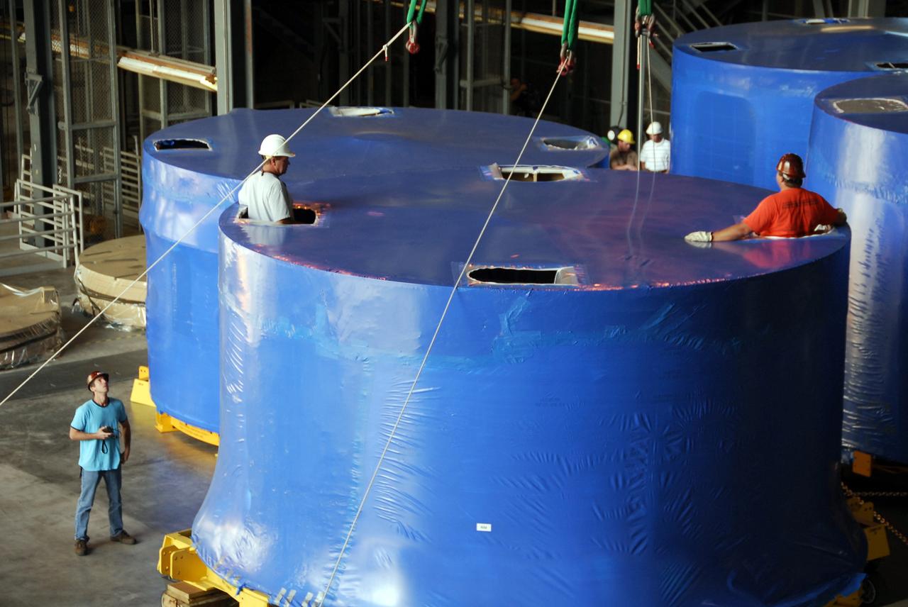
CAPE CANAVERAL, Fla. – Inside the Vehicle Assembly Building's high bay 4 at NASA's Kennedy Space Center in Florida, workers secure the cranes that are being used to offload Ares I-X upper stage simulator segments onto the floor. The segments arrived Nov. 4 at Port Canaveral, Fla., aboard the Delta Mariner. The upper simulator segments are moved inside where they will be offloaded. The upper stage simulators will be used in the test flight identified as Ares I-X in 2009. The Ares I-X test flight will provide NASA an early opportunity to test and prove hardware, facilities and ground operations associated with the Ares I crew launch vehicle. It also will allow NASA to gather critical data during ascent of the integrated Orion crew exploration vehicle and the Ares I rocket. The data will ensure the entire vehicle system is safe and fully operational before astronauts begin traveling to orbit. The simulator segments will simulate the mass and the outer mold line and will be more than 100 feet of the total vehicle height of 327 feet. The simulator comprises 11 segments that are approximately 18 feet in diameter. Most of the segments will be approximately 10 feet high, ranging in weight from 18,000 to 60,000 pounds, for a total of approximately 450,000 pounds. Photo credit: NASA/Cory Huston
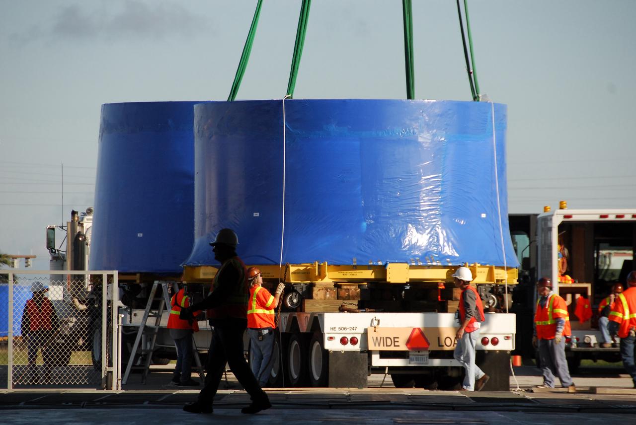
CAPE CANAVERAL, Fla. – A crane lifts and transfers an Ares I-X upper stage simulator segment from the Delta Mariner at Port Canaveral, Fla., onto a flatbed truck. They will be transported to the Vehicle Assembly Building's high bay 4 at NASA's Kennedy Space Center in Florida. The upper stage simulators will be used in the test flight identified as Ares I-X in 2009. The Ares I-X test flight will provide NASA an early opportunity to test and prove hardware, facilities and ground operations associated with the Ares I crew launch vehicle. It also will allow NASA to gather critical data during ascent of the integrated Orion crew exploration vehicle and the Ares I rocket. The data will ensure the entire vehicle system is safe and fully operational before astronauts begin traveling to orbit. The simulator segments will simulate the mass and the outer mold line and will be more than 100 feet of the total vehicle height of 327 feet. The simulator comprises 11 segments that are approximately 18 feet in diameter. Most of the segments will be approximately 10 feet high, ranging in weight from 18,000 to 60,000 pounds, for a total of approximately 450,000 pounds. Photo credit: NASA/Cory Huston
CAPE CANAVERAL, Fla. – The Ares I-X upper stage simulator segments are being offloaded from the Delta Mariner at Port Canaveral, Fla. The segments will be placed on a flatbed truck for transportation to the Vehicle Assembly Building's high bay 4 at NASA's Kennedy Space Center in Florida. The upper stage simulator will be used in the test flight identified as Ares I-X in 2009. The Ares I-X test flight will provide NASA an early opportunity to test and prove hardware, facilities and ground operations associated with the Ares I crew launch vehicle. It also will allow NASA to gather critical data during ascent of the integrated Orion crew exploration vehicle and the Ares I rocket. The data will ensure the entire vehicle system is safe and fully operational before astronauts begin traveling to orbit. The simulator segments will simulate the mass and the outer mold line and will be more than 100 feet of the total vehicle height of 327 feet. The simulator comprises 11 segments that are approximately 18 feet in diameter. Most of the segments will be approximately 10 feet high, ranging in weight from 18,000 to 60,000 pounds, for a total of approximately 450,000 pounds. Photo credit: NASA/Cory Huston
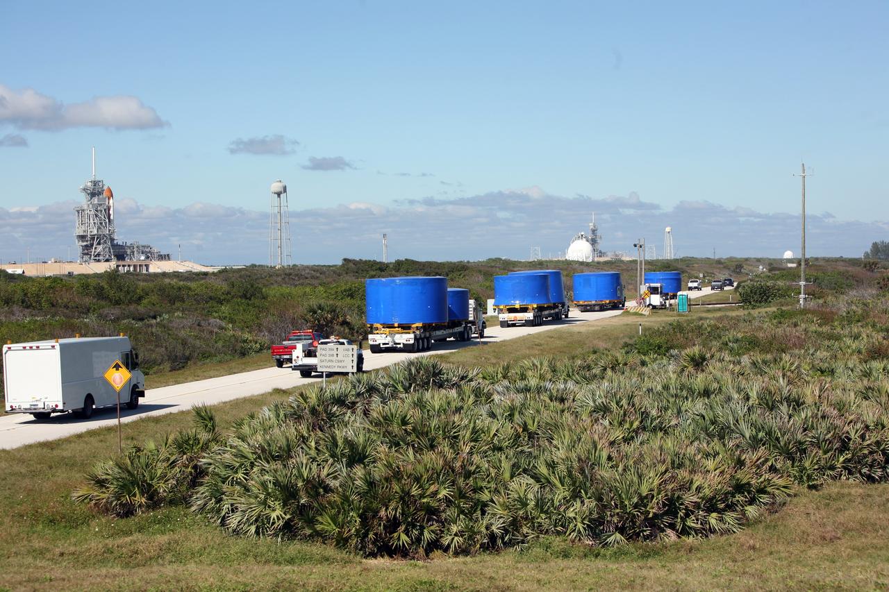
CAPE CANAVERAL, Fla. – A convoy of trucks passes a launch pad as it makes the journey from Port Canaveral, Fla., to the Vehicle Assembly Building's high bay 4 at NASA's Kennedy Space Center in Florida. The trucks carry Ares I-X upper stage simulator segments. The upper stage simulator will be used in the test flight identified as Ares I-X in 2009. The Ares I-X test flight will provide NASA an early opportunity to test and prove hardware, facilities and ground operations associated with the Ares I crew launch vehicle. It also will allow NASA to gather critical data during ascent of the integrated Orion crew exploration vehicle and the Ares I rocket. The data will ensure the entire vehicle system is safe and fully operational before astronauts begin traveling to orbit. The simulator segments will simulate the mass and the outer mold line and will be more than 100 feet of the total vehicle height of 327 feet. The simulator comprises 11 segments that are approximately 18 feet in diameter. Most of the segments will be approximately 10 feet high, ranging in weight from 18,000 to 60,000 pounds, for a total of approximately 450,000 pounds. Photo credit: NASA/Cory Huston
CAPE CANAVERAL, Fla. – Ares I-X upper stage simulator segments arrive at the Vehicle Assembly Building's high bay 4 at NASA's Kennedy Space Center in Florida. The segments will be offloaded inside bay 4. The upper stage simulator will be used in the test flight identified as Ares I-X in 2009. The Ares I-X test flight will provide NASA an early opportunity to test and prove hardware, facilities and ground operations associated with the Ares I crew launch vehicle. It also will allow NASA to gather critical data during ascent of the integrated Orion crew exploration vehicle and the Ares I rocket. The data will ensure the entire vehicle system is safe and fully operational before astronauts begin traveling to orbit. The simulator segments will simulate the mass and the outer mold line and will be more than 100 feet of the total vehicle height of 327 feet. The simulator comprises 11 segments that are approximately 18 feet in diameter. Most of the segments will be approximately 10 feet high, ranging in weight from 18,000 to 60,000 pounds, for a total of approximately 450,000 pounds. Photo credit: NASA/Cory Huston
CAPE CANAVERAL, Fla. – Ares I-X upper stage simulator segments arrive at the Vehicle Assembly Building's high bay 4 at NASA's Kennedy Space Center in Florida. The upper stage simulator will be used in the test flight identified as Ares I-X in 2009. The Ares I-X test flight will provide NASA an early opportunity to test and prove hardware, facilities and ground operations associated with the Ares I crew launch vehicle. It also will allow NASA to gather critical data during ascent of the integrated Orion crew exploration vehicle and the Ares I rocket. The data will ensure the entire vehicle system is safe and fully operational before astronauts begin traveling to orbit. The simulator segments will simulate the mass and the outer mold line and will be more than 100 feet of the total vehicle height of 327 feet. The simulator comprises 11 segments that are approximately 18 feet in diameter. Most of the segments will be approximately 10 feet high, ranging in weight from 18,000 to 60,000 pounds, for a total of approximately 450,000 pounds. Photo credit: NASA/Cory Huston
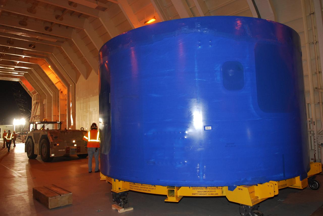
CAPE CANAVERAL, Fla. – At the Vehicle Assembly Building's high bay 4 at NASA's Kennedy Space Center in Florida, the blue Ares I-X upper stage simulator segments are moved inside where they will be offloaded. The upper stage simulators will be used in the test flight identified as Ares I-X in 2009. The Ares I-X test flight will provide NASA an early opportunity to test and prove hardware, facilities and ground operations associated with the Ares I crew launch vehicle. It also will allow NASA to gather critical data during ascent of the integrated Orion crew exploration vehicle and the Ares I rocket. The data will ensure the entire vehicle system is safe and fully operational before astronauts begin traveling to orbit. The simulator segments will simulate the mass and the outer mold line and will be more than 100 feet of the total vehicle height of 327 feet. The simulator comprises 11 segments that are approximately 18 feet in diameter. Most of the segments will be approximately 10 feet high, ranging in weight from 18,000 to 60,000 pounds, for a total of approximately 450,000 pounds. Photo credit: NASA/Cory Huston
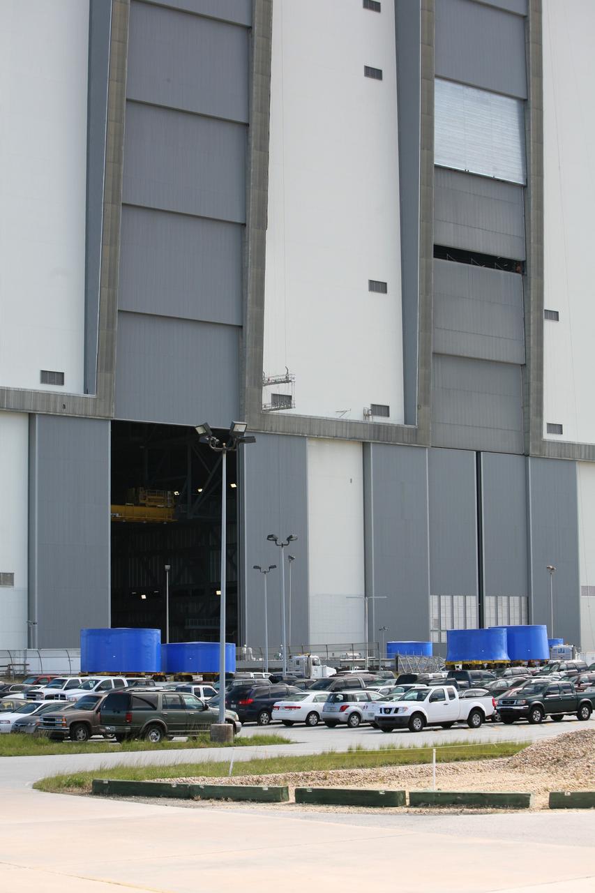
CAPE CANAVERAL, Fla. – Trucks carrying the blue Ares I-X upper stage simulator segments are lined up outside the Vehicle Assembly Building's high bay 4 at NASA's Kennedy Space Center in Florida. The segments will be offloaded inside bay 4. The upper stage simulators will be used in the test flight identified as Ares I-X in 2009. The Ares I-X test flight will provide NASA an early opportunity to test and prove hardware, facilities and ground operations associated with the Ares I crew launch vehicle. It also will allow NASA to gather critical data during ascent of the integrated Orion crew exploration vehicle and the Ares I rocket. The data will ensure the entire vehicle system is safe and fully operational before astronauts begin traveling to orbit. The simulator segments will simulate the mass and the outer mold line and will be more than 100 feet of the total vehicle height of 327 feet. The simulator comprises 11 segments that are approximately 18 feet in diameter. Most of the segments will be approximately 10 feet high, ranging in weight from 18,000 to 60,000 pounds, for a total of approximately 450,000 pounds. Photo credit: NASA/Cory Huston
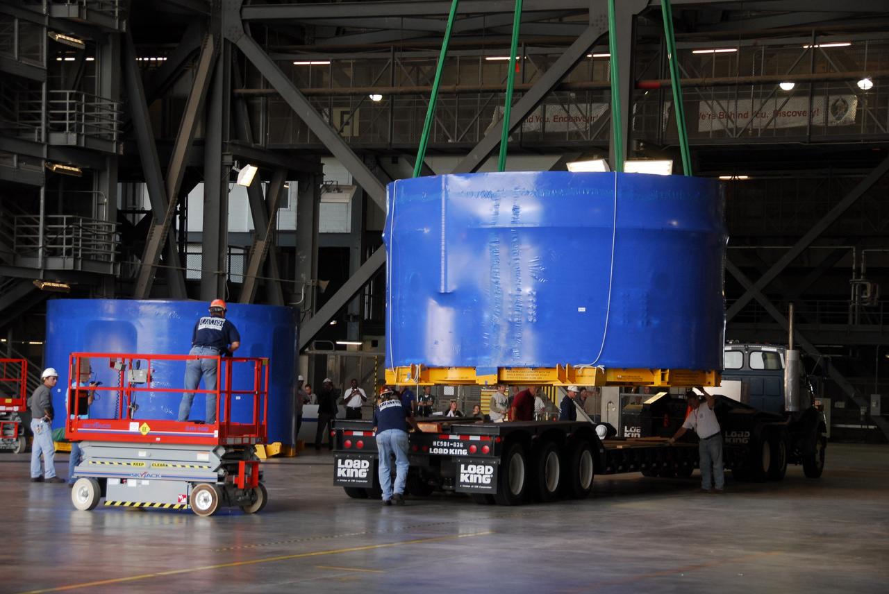
CAPE CANAVERAL, Fla. – Inside the Vehicle Assembly Building's high bay 4 at NASA's Kennedy Space Center in Florida, workers secure the crane that will lift one of the Ares I-X upper stage simulator segments from its transporter. The segments, which arrived Nov. 4 at Port Canaveral, Fla., aboard the Delta Mariner, will be placed on the floor. The upper simulator segments are moved inside where they will be offloaded. The upper stage simulators will be used in the test flight identified as Ares I-X in 2009. The Ares I-X test flight will provide NASA an early opportunity to test and prove hardware, facilities and ground operations associated with the Ares I crew launch vehicle. It also will allow NASA to gather critical data during ascent of the integrated Orion crew exploration vehicle and the Ares I rocket. The data will ensure the entire vehicle system is safe and fully operational before astronauts begin traveling to orbit. The simulator segments will simulate the mass and the outer mold line and will be more than 100 feet of the total vehicle height of 327 feet. The simulator comprises 11 segments that are approximately 18 feet in diameter. Most of the segments will be approximately 10 feet high, ranging in weight from 18,000 to 60,000 pounds, for a total of approximately 450,000 pounds. Photo credit: NASA/Cory Huston
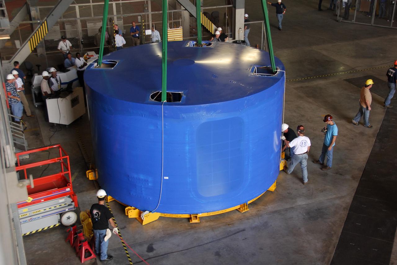
CAPE CANAVERAL, Fla. – Inside the Vehicle Assembly Building's high bay 4 at NASA's Kennedy Space Center in Florida, one of the Ares I-X upper stage simulator segments is offloaded from its transporter and placed on the floor. The segments arrived Nov. 4 at Port Canaveral, Fla., aboard the Delta Mariner. The upper stage simulators will be used in the test flight identified as Ares I-X in 2009. The Ares I-X test flight will provide NASA an early opportunity to test and prove hardware, facilities and ground operations associated with the Ares I crew launch vehicle. It also will allow NASA to gather critical data during ascent of the integrated Orion crew exploration vehicle and the Ares I rocket. The data will ensure the entire vehicle system is safe and fully operational before astronauts begin traveling to orbit. The simulator segments will simulate the mass and the outer mold line and will be more than 100 feet of the total vehicle height of 327 feet. The simulator comprises 11 segments that are approximately 18 feet in diameter. Most of the segments will be approximately 10 feet high, ranging in weight from 18,000 to 60,000 pounds, for a total of approximately 450,000 pounds. Photo credit: NASA/Cory Huston
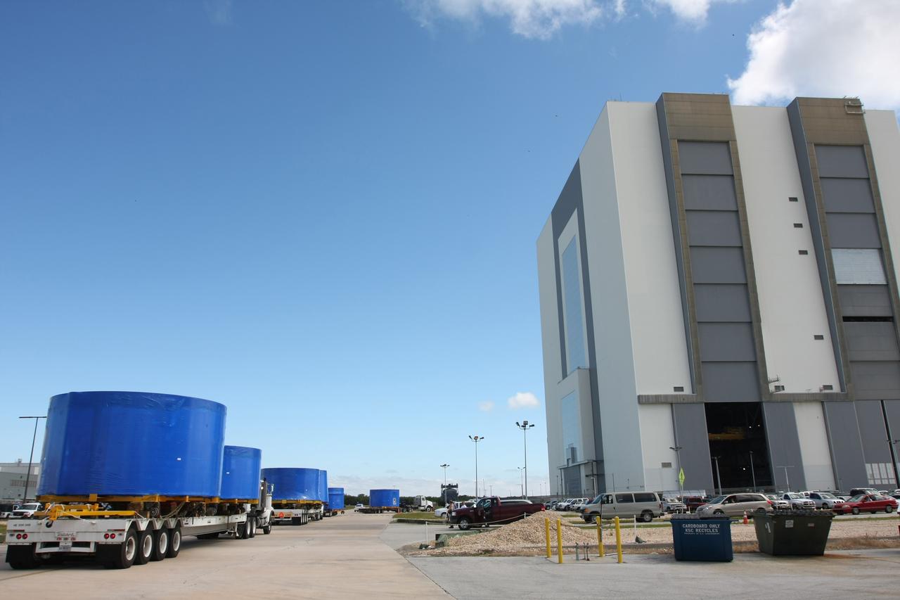
CAPE CANAVERAL, Fla. – A convoy of trucks arrives at the Vehicle Assembly Building's high bay 4 at NASA's Kennedy Space Center in Florida. The trucks carry Ares I-X upper stage simulator segments which arrived at Port Canaveral, Fla., Nov. 4. The upper stage simulators will be used in the test flight identified as Ares I-X in 2009. The Ares I-X test flight will provide NASA an early opportunity to test and prove hardware, facilities and ground operations associated with the Ares I crew launch vehicle. It also will allow NASA to gather critical data during ascent of the integrated Orion crew exploration vehicle and the Ares I rocket. The data will ensure the entire vehicle system is safe and fully operational before astronauts begin traveling to orbit. The simulator segments will simulate the mass and the outer mold line and will be more than 100 feet of the total vehicle height of 327 feet. The simulator comprises 11 segments that are approximately 18 feet in diameter. Most of the segments will be approximately 10 feet high, ranging in weight from 18,000 to 60,000 pounds, for a total of approximately 450,000 pounds. Photo credit: NASA/Cory Huston
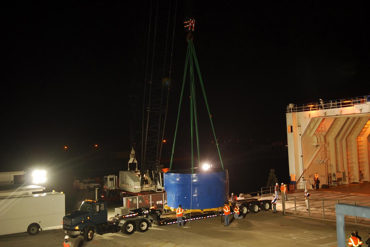
CAPE CANAVERAL, Fla. – A crane lifts and transfers an Ares I-X upper stage simulator segment from the Delta Mariner at Port Canaveral, Fla., onto a flatbed truck. They will be transported to the Vehicle Assembly Building's high bay 4 at NASA's Kennedy Space Center in Florida. The upper stage simulator will be used in the test flight identified as Ares I-X in 2009. The Ares I-X test flight will provide NASA an early opportunity to test and prove hardware, facilities and ground operations associated with the Ares I crew launch vehicle. It also will allow NASA to gather critical data during ascent of the integrated Orion crew exploration vehicle and the Ares I rocket. The data will ensure the entire vehicle system is safe and fully operational before astronauts begin traveling to orbit. The simulator segments will simulate the mass and the outer mold line and will be more than 100 feet of the total vehicle height of 327 feet. The simulator comprises 11 segments that are approximately 18 feet in diameter. Most of the segments will be approximately 10 feet high, ranging in weight from 18,000 to 60,000 pounds, for a total of approximately 450,000 pounds. Photo credit: NASA/Cory Huston
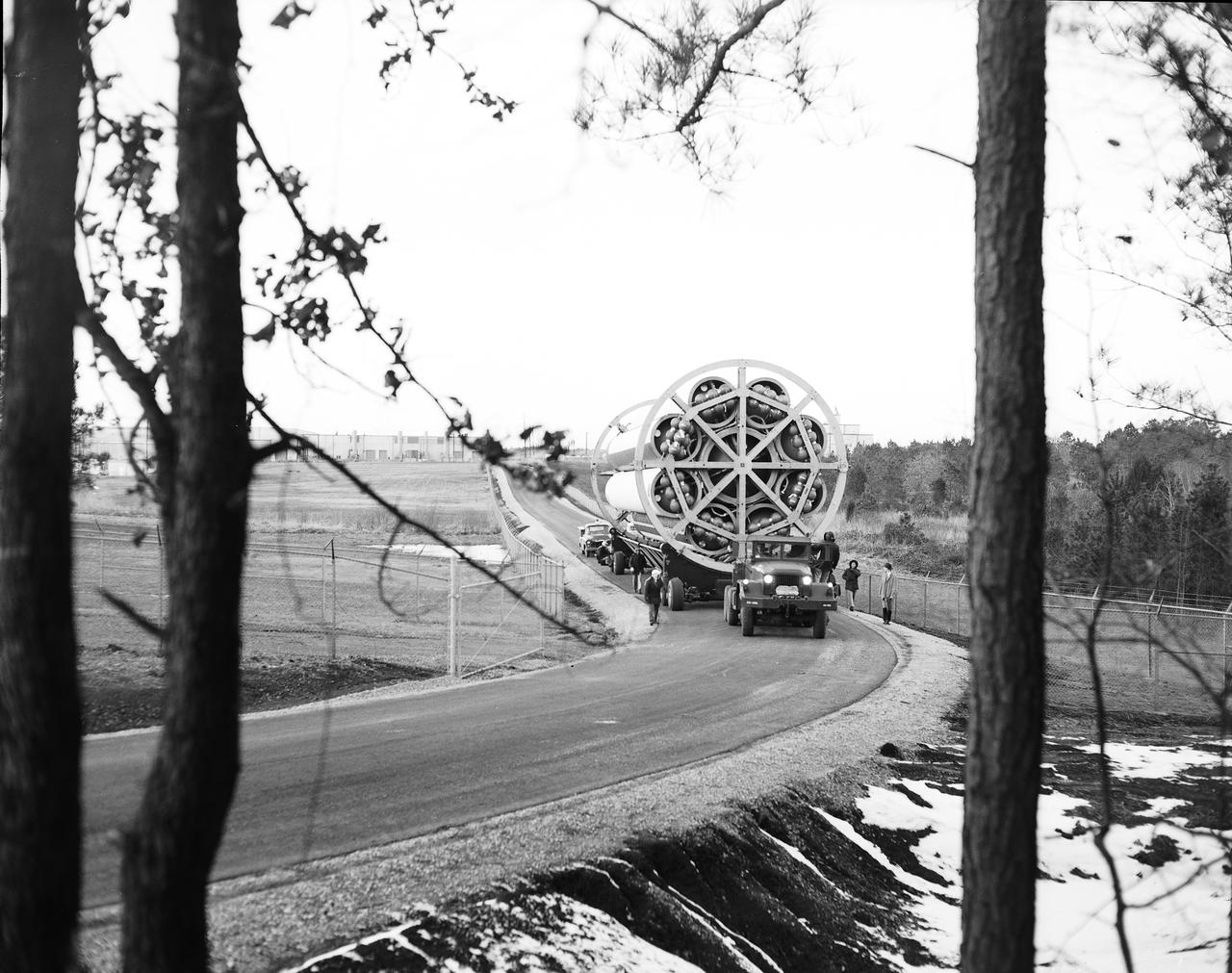
This photograph shows the Saturn-I first stage (S-1 stage) being transported to the test stand for a static test firing at the Marshall Space Flight Center. Soon after NASA began operations in October 1958, it was evident that sending people and substantial equipment beyond the Earth's gravitational field would require launch vehicles with weight-lifting capabilities far beyond any developed to that time. In early 1959, NASA accepted the proposal of Dr. Wernher von Braun for a multistage rocket, with a number of engines clustered in one or more of the stages to provide a large total thrust. The initiation of the Saturn launch vehicle program ultimately led to the study and preliminary plarning of many different configurations and resulted in production of three Saturn launch vehicles, the Saturn-I, Saturn I-B, and Saturn V. The Saturn family of launch vehicles began with the Saturn-I, a two-stage vehicle originally designated C-1. The research and development program was planned in two phases, or blocks: one for first stage development (Block I) and the second for both first and second stage development (Block-II). Saturn I had a low-earth-orbit payload capability of approximately 25,000 pounds. The design of the first stage (S-1 stage) used a cluster of propellant tanks containing liquid oxygen (LOX) and kerosene (RP-1), and eight H-1 engines, yielding a total thrust of 1,500,000 pounds. Of the ten Saturn-Is planned, the first eight were designed and built at the Marshall Space Flight Center, and the remaining two were built by the Chrysler Corporation.
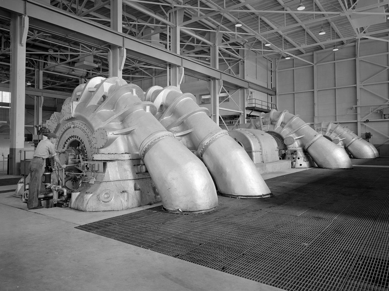
The Propulsion Systems Laboratory’s exhaust system was expanded in 1955 at the National Advisory Committee for Aeronautics (NACA) Lewis Flight Propulsion Laboratory. The facility contained two altitude chambers that were first used to study the increasingly-powerful jet engines of the early 1950s and the ramjets for missile programs such as Navaho and Bomarc. Later, the facility tested large rocket engines and a variety of turbofan engines. The exhaust system served two roles: reducing the density of the air in the test chambers to simulate high altitudes and removing the hot gases exhausted by the engines being tested. These tasks were accomplished by large Roots-Connersville exhauster equipment in the Equipment Building. The original configuration could exhaust the 3500° F gases at a rate of 100 pounds per second when the simulated altitude was 50,000 feet. In 1955, three years after operation started, a fourth line of exhausters was added. There were three centrifugal exhausters capable of supplying 166 pounds of air per second at the test chamber altitude of 50,000 feet or 384 pounds per second at 32,000 feet. These exhausters had two first-stage castings driven by a 10,000-horsepower motor; one second; one third; and one fourth-stage casting driven by a 16,500-horsepower motor. The total inlet volume of the exhausters is 1,650,000 cubic feet of gas per minute. The exhausters were continually improved and upgraded over the years.
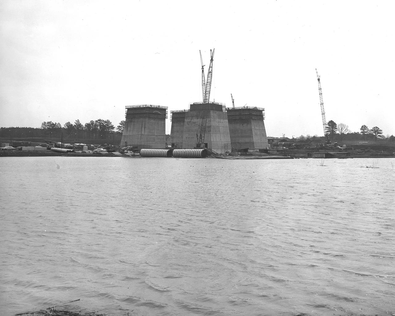
At its founding, the Marshall Space Flight Center (MSFC) inherited the Army’s Jupiter and Redstone test stands, but much larger facilities were needed for the giant stages of the Saturn V. From 1960 to 1964, the existing stands were remodeled and a sizable new test area was developed. The new comprehensive test complex for propulsion and structural dynamics was unique within the nation and the free world, and they remain so today because they were constructed with foresight to meet the future as well as on going needs. Construction of the S-IC Static test stand complex began in 1961 in the west test area of MSFC, and was completed in 1964. The S-IC static test stand was designed to develop and test the 138-ft long and 33-ft diameter Saturn V S-IC first stage, or booster stage, weighing in at 280,000 pounds. Required to hold down the brute force of a 7,500,000-pound thrust produced by 5 F-1 engines, the S-IC static test stand was designed and constructed with the strength of hundreds of tons of steel and 12,000,000 pounds of cement, planted down to bedrock 40 feet below ground level. The foundation walls, constructed with concrete and steel, are 4 feet thick. The base structure consists of four towers with 40-foot-thick walls extending upward 144 feet above ground level. The structure was topped by a crane with a 135-foot boom. With the boom in the upright position, the stand was given an overall height of 405 feet, placing it among the highest structures in Alabama at the time. In the early stages of excavation, a natural spring was disturbed that caused a water problem which required constant pumping from the site and is even pumped to this day. Behind this reservoir of pumped water is the S-IC test stand boasting its ever-growing four towers as of March 29, 1963.

At its founding, the Marshall Space Flight Center (MSFC) inherited the Army’s Jupiter and Redstone test stands, but much larger facilities were needed for the giant stages of the Saturn V. From 1960 to 1964, the existing stands were remodeled and a sizable new test area was developed. The new comprehensive test complex for propulsion and structural dynamics was unique within the nation and the free world, and they remain so today because they were constructed with foresight to meet the future as well as on going needs. Construction of the S-IC Static test stand complex began in 1961 in the west test area of MSFC, and was completed in 1964. The S-IC static test stand was designed to develop and test the 138-ft long and 33-ft diameter Saturn V S-IC first stage, or booster stage, weighing in at 280,000 pounds. Required to hold down the brute force of a 7,500,000-pound thrust produced by 5 F-1 engines, the S-IC static test stand was designed and constructed with the strength of hundreds of tons of steel and 12,000,000 pounds of cement, planted down to bedrock 40 feet below ground level. The foundation walls, constructed with concrete and steel, are 4 feet thick. The base structure consists of four towers with 40-foot-thick walls extending upward 144 feet above ground level. The structure was topped by a crane with a 135-foot boom. With the boom in the upright position, the stand was given an overall height of 405 feet, placing it among the highest structures in Alabama at the time. In this early construction photo, taken June 30, 1961, workers are are involved in the survey and site preparation of the test stand.

At its founding, the Marshall Space Flight Center (MSFC) inherited the Army’s Jupiter and Redstone test stands, but much larger facilities were needed for the giant stages of the Saturn V. From 1960 to 1964, the existing stands were remodeled and a sizable new test area was developed. The new comprehensive test complex for propulsion and structural dynamics was unique within the nation and the free world, and they remain so today because they were constructed with foresight to meet the future as well as on going needs. Construction of the S-IC Static test stand complex began in 1961 in the west test area of MSFC, and was completed in 1964. The S-IC static test stand was designed to develop and test the 138-ft long and 33-ft diameter Saturn V S-IC first stage, or booster stage, weighing in at 280,000 pounds. Required to hold down the brute force of a 7,500,000-pound thrust produced by 5 F-1 engines, the S-IC static test stand was designed and constructed with the strength of hundreds of tons of steel and 12,000,000 pounds of cement, planted down to bedrock 40 feet below ground level. The foundation walls, constructed with concrete and steel, are 4 feet thick. The base structure consists of four towers with 40-foot-thick walls extending upward 144 feet above ground level. The structure was topped by a crane with a 135-foot boom. With the boom in the upright position, the stand was given an overall height of 405 feet, placing it among the highest structures in Alabama at the time. In this early construction photo, taken June 30, 1961, workers are involved in the survey and site preparation for the test stand.
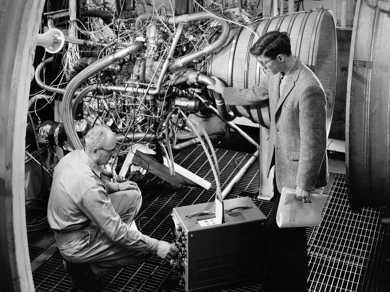
Lead Test Engineer John Kobak (right) and a technician use an oscilloscope to test the installation of a Pratt and Whitney RL-10 engine in the Propulsion Systems Laboratory at the National Aeronautics and Space Administration (NASA) Lewis Research Center. In 1955 the military asked Pratt and Whitney to develop hydrogen engines specifically for aircraft. The program was canceled in 1958, but Pratt and Whitney decided to use the experience to develop a liquid-hydrogen rocket engine, the RL-10. Two of the 15,000-pound-thrust RL-10 engines were used to power the new Centaur second-stage rocket. Centaur was designed to carry the Surveyor spacecraft on its mission to soft-land on the Moon. Pratt and Whitney ran into problems while testing the RL-10 at their facilities. NASA Headquarters assigned Lewis the responsibility for investigating the RL-10 problems because of the center’s long history of liquid-hydrogen development. Lewis’ Chemical Rocket Division began a series of tests to study the RL-10 at its Propulsion Systems Laboratory in March 1960. The facility contained two test chambers that could study powerful engines in simulated altitude conditions. The first series of RL-10 tests in early 1961 involved gimballing the engine as it fired. Lewis researchers were able to yaw and pitch the engine to simulate its behavior during a real flight.
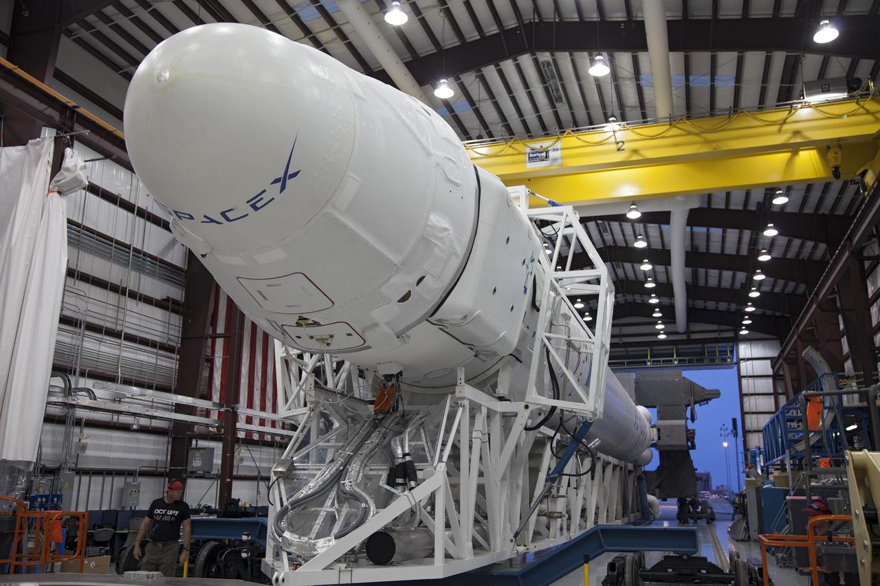
CAPE CANAVERAL, Fla. - The SpaceX Falcon 9 rocket begins its early morning move out of the company's Falcon Hangar at Launch Complex 40 on Cape Canaveral Air Force Station in Florida. Topped by the Dragon spacecraft, the rocket is rolling to the launch pad for a test firing of its nine Merlin first-stage engines in preparation for the SpaceX 2 launch. Liftoff of the SpaceX Falcon 9 rocket and Dragon spacecraft is planned for March 1, 2013, at 10:10 a.m. EST, from Space Launch Complex-40 at Cape Canaveral Air Force Station, Fla. Dragon will be making its third trip to the space station. It will carry supplies and experiments to the orbiting laboratory. The mission is the second of 12 SpaceX flights contracted by NASA to resupply the space station. For more information, visit http:__www.nasa.gov_mission_pages_station_structure_launch_spacex2-feature.html Photo credit: NASA_Frankie Martin
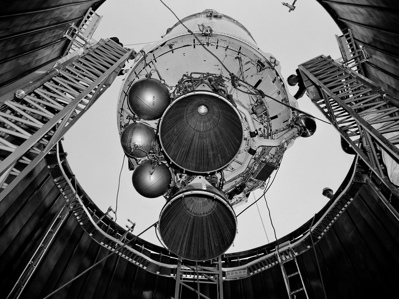
A Centaur second-stage rocket is lowered into the vacuum tank inside the Space Power Chambers at NASA’s Lewis Research Center. Centaur was to be paired with an Atlas booster to send the Surveyor spacecraft to the moon as a precursor to the Apollo landings. Lewis was assigned responsibility for the Centaur Program after the failure of its first developmental flight in May 1962. Lewis’ Altitude Wind Tunnel was converted into two large test chambers—the Space Power Chambers. The facility’s vacuum chamber, seen here, allowed the Centaur to be stood up vertically and subjected to atmospheric conditions-- pressures, temperature, and radiation--similar to those it would encounter in space. The Centaur for these tests was delivered to Cleveland in a C‒130 aircraft on September 27, 1963. The rocket was set up in the facility’s high bay where Lewis technicians and General Dynamics consultants updated its flight systems to match the upcoming Atlas-Centaur‒4 mission. Months were spent reharnessing the Centaur’s electronics, learning about the systems, and being taught how to handle flight hardware. By early spring 1964, the extensive setup of both the spacecraft and the chamber was finally completed. On March 19 the Centaur was rolled out from the shop, hoisted high into the air by a crane, and lowered into the waiting space tank. Researchers were able to verify that the Centaur’s electronics and electrical systems functioned reliably in a space environment.
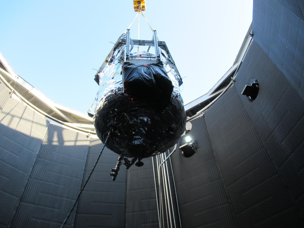
These photos show how teams at NASA’s Marshall Space Flight Center in Huntsville, Alabama, are testing an innovative approach to achieve zero boiloff storage of liquid hydrogen using two stages of active cooling, which could prevent the loss of valuable propellant during future long-duration spaceflight missions. Test teams installed the propellant tank in Test Stand 300 at NASA Marshall in early June, and the 90-day test campaign is scheduled to conclude in September. The tank is wrapped in a multi-layer insulation blanket that includes a thin aluminum heat shield fitted between layers. A second set of tubes, carrying helium at about minus 298 Fahrenheit, is integrated into the shield. This intermediate cooling layer intercepts and rejects incoming heat before it reaching the tank, easing the heat load on the tube-on-tank system. The Cryogenic Fluid Management Portfolio Project is a cross-agency team based at NASA Marshall and the agency’s Glenn Research Center in Cleveland. The cryogenic portfolio’s work is under NASA’s Technology Demonstration Missions Program, part of NASA’s Space Technology Mission Directorate, and is comprised of more than 20 individual technology development activities. For more information, contact NASA Marshall’s Office of Communications at 256-544-0034.
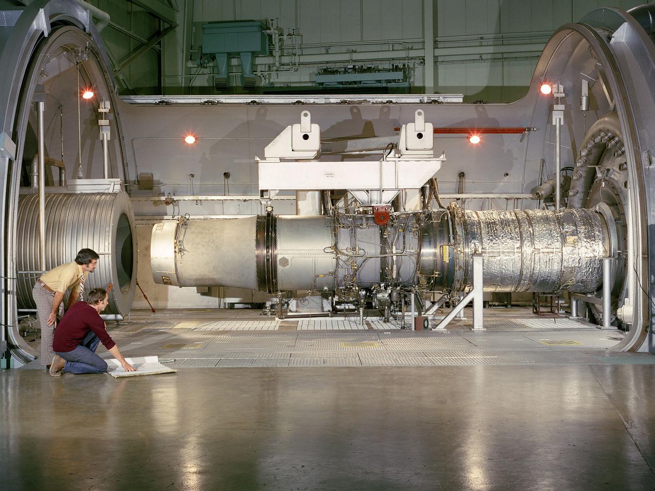
A refanned Pratt and Whitney JT-8D-109 turbofan engine installed in Cell 4 of the Propulsion Systems Laboratory at the National Aeronautics and Space Administration (NASA) Lewis Research Center. NASA Lewis’ Refan Program sought to demonstrate that noise reduction modifications could be applied to existing aircraft engines with minimal costs and without diminishing the engine’s performance or integrity. At the time, Pratt and Whitney’s JT-8D turbofans were one of the most widely used engines in the commercial airline industry. The engines powered Boeing’s 727 and 737 and McDonnell Douglas’ DC-9 aircraft. Pratt and Whitney worked with the airline manufacturers on a preliminary study that verified feasibility of replacing the JT-8D’s two-stage fan with a larger single-stage fan. The new fan slowed the engine’s exhaust, which significantly reduced the amount of noise it generated. Booster stages were added to maintain the proper level of airflow through the engine. Pratt and Whitney produced six of the modified engines, designated JT-8D-109, and performed the initial testing. One of the JT-8D-109 engines, seen here, was tested in simulated altitude conditions in NASA Lewis’ Propulsion Systems Laboratory. The Refan engine was ground-tested on an actual aircraft before making a series of flight tests on 727 and DC-9 aircraft in early 1976. The Refan Program reduced the JT-8D’s noise by 50 percent while increasing the fuel efficiency. The retro-fit kits were estimated to cost between $1 million and $1.7 million per aircraft.
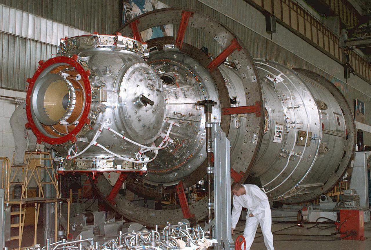
The Zvezda Service Module, the first Russian contribution and third element to the International Space Station (ISS), is shown under construction in the Krunichev State Research and Production Facility (KhSC) in Moscow. Russian technicians work on the module shortly after it completed a pressurization test. In the foreground is the forward portion of the module, including the spherical transfer compartment and its three docking ports. The forward port docked with the cornected Functional Cargo Block, followed by Node 1. Launched via a three-stage Proton rocket on July 12, 2000, the Zvezda Service Module serves as the cornerstone for early human habitation of the Station, providing living quarters, life support system, electrical power distribution, data processing system, flight control system, and propulsion system. It also provides a communications system that includes remote command capabilities from ground flight controllers. The 42,000-pound module measures 43 feet in length and has a wing span of 98 feet. Similar in layout to the core module of Russia's Mir space station, it contains 3 pressurized compartments and 13 windows that allow ultimate viewing of Earth and space.
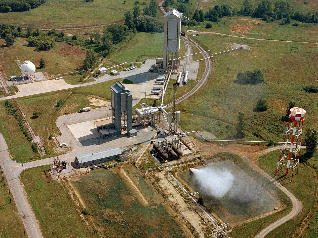
Operation of the High Energy Rocket Engine Research Facility (B-1), left, and Nuclear Rocket Dynamics and Control Facility (B-3) at the National Aeronautics and Space Administration’s (NASA) Plum Brook Station in Sandusky, Ohio. The test stands were constructed in the early 1960s to test full-scale liquid hydrogen fuel systems in simulated altitude conditions. Over the next decade each stand was used for two major series of liquid hydrogen rocket tests: the Nuclear Engine for Rocket Vehicle Application (NERVA) and the Centaur second-stage rocket program. The different components of these rocket engines could be studied under flight conditions and adjusted without having to fire the engine. Once the preliminary studies were complete, the entire engine could be fired in larger facilities. The test stands were vertical towers with cryogenic fuel and steam ejector systems. B-1 was 135 feet tall, and B-3 was 210 feet tall. Each test stand had several levels, a test section, and ground floor shop areas. The test stands relied on an array of support buildings to conduct their tests, including a control building, steam exhaust system, and fuel storage and pumping facilities. A large steam-powered altitude exhaust system reduced the pressure at the exhaust nozzle exit of each test stand. This allowed B-1 and B-3 to test turbopump performance in conditions that matched the altitudes of space.
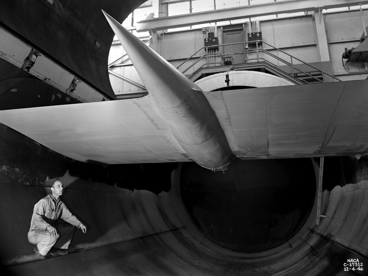
A General Electric TG-100A seen from the rear in the test section of the Altitude Wind Tunnel at the National Advisory Committee for Aeronautics (NACA) Lewis Flight Propulsion Laboratory in Cleveland, Ohio. The Altitude Wind Tunnel was used to study almost every model of US turbojet that emerged in the 1940s, as well as some ramjets and turboprops. In the early 1940s the military was interested in an engine that would use less fuel than the early jets but would keep up with them performance-wise. Turboprops seemed like a plausible solution. They could move a large volume of air and thus required less engine speed and less fuel. Researchers at General Electric’s plant in Schenectady, New York worked on the turboprop for several years in the 1930s. They received an army contract in 1941 to design a turboprop engine using an axial-flow compressor. The result was the 14-stage TG-100, the nation's first turboprop aircraft engine. Development of the engine was slow, however, and the military asked NACA Lewis to analyze the engine’s performance. The TG-100A was tested in the Altitude Wind Tunnel and it was determined that the compressors, combustion chamber, and turbine were impervious to changes in altitude. The researchers also established the optimal engine speed and propeller angle at simulated altitudes up to 35,000 feet. Despite these findings, development of the TG-100 was cancelled in May 1947. Twenty-eight of the engines were produced, but they were never incorporated into production aircraft.
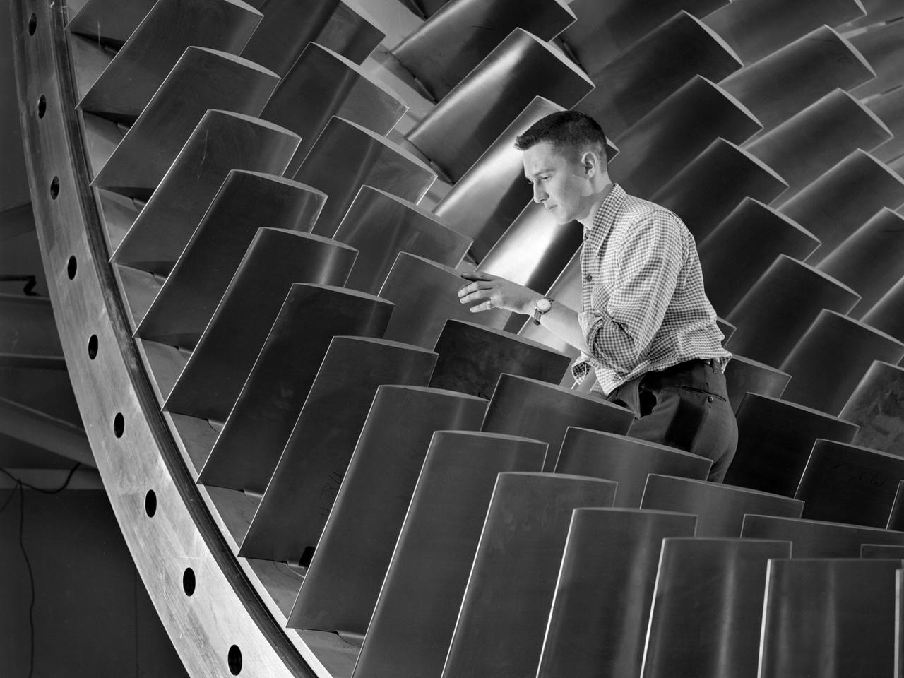
An engineer examines the main compressor for the 10- by 10-Foot Supersonic Wind Tunnel at the National Advisory Committee for Aeronautics (NACA) Lewis Flight Propulsion Laboratory. The engineers were preparing the new wind tunnel for its initial runs in early 1956. The 10- by 10 was the most powerful propulsion wind tunnel in the nation. The facility was part of Congress’ Unitary Plan Act which coordinated wind tunnel construction at the NACA, Air Force, industry, and universities. The 10- by 10 was the largest of the three NACA tunnels built under the act. The 20-foot diameter eight-stage axial flow compressor, seen in this photograph, could generate air flows up to Mach 2.5 through the test section. The stainless steel compressor had 584 blades ranging from 1.8 to 3.25 feet in length. This main compressor was complemented by a secondary axial flow compressor. Working in tandem the two could generate wind streams up to Mach 3.5. The Cleveland Chamber of Commerce presented NACA Lewis photographer Bill Bowles with a second place award for this photograph in their Business and Professional category. The photograph was published in October 1955 edition of its periodical, The Clevelander, which highlighted local professional photographers. Fellow Lewis photographer Gene Giczy won second place in another category for a photograph of Cleveland Municipal Airport.
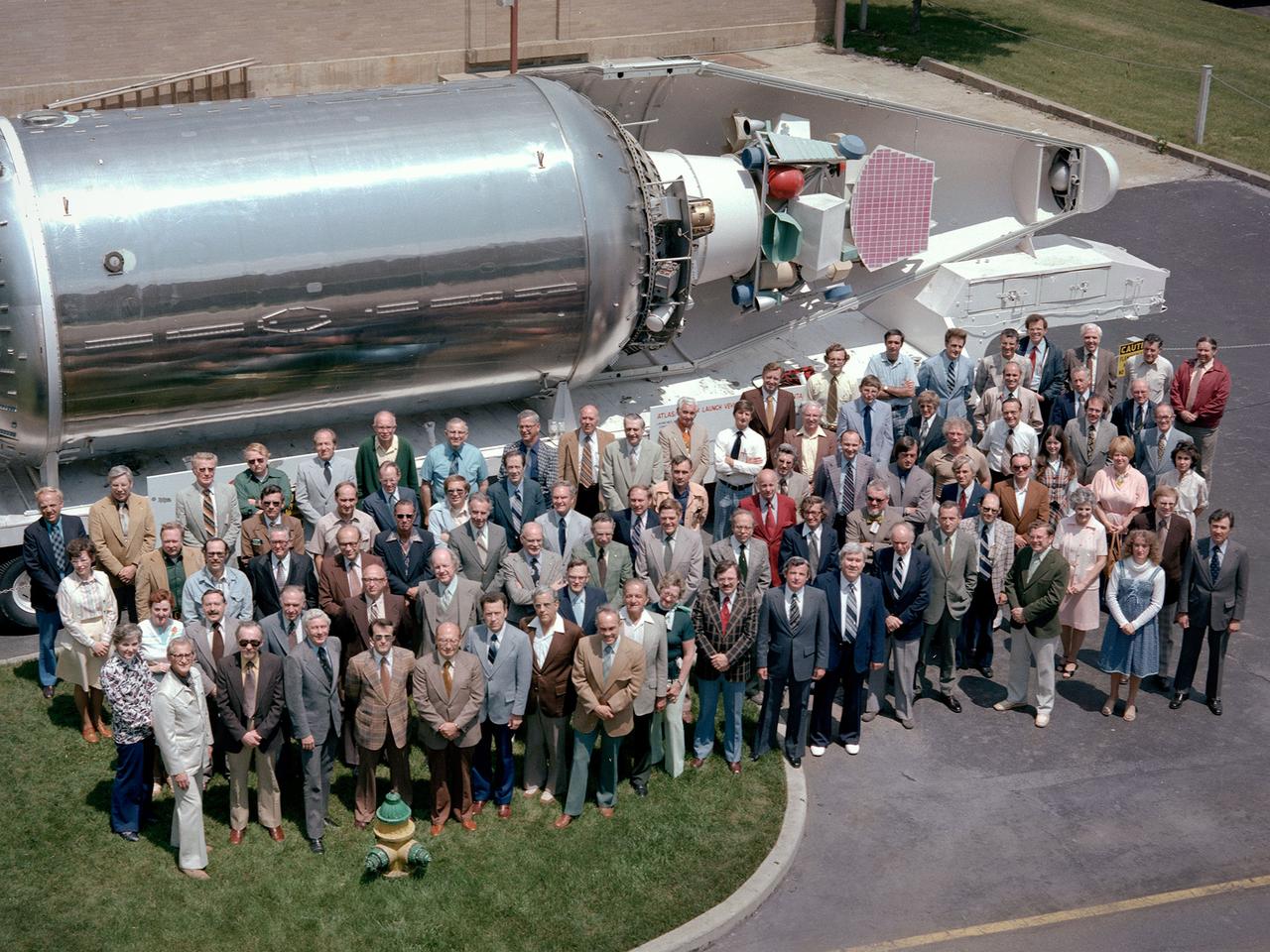
The National Aeronautics and Space Administration (NASA) Lewis Research Center’s Launch Vehicle Directorate in front of a full-scale model of the Centaur second-stage rocket. The photograph was taken to mark Centaur’s fiftieth launch. NASA Lewis managed the Centaur Program since 1962. At that time, the only prior launch attempt ended in failure. Lewis improved the spacecraft and tested it extensively throughout the early 1960s. In May 1966 an Atlas-Centaur sent the Surveyor spacecraft to the moon. It was the first successful soft landing on another planet. The Launch Vehicles Division was formed in 1969 to handle the increasing number of Centaur launches. The Lewis team became experts at integrating the payload with the Centaur and calculating proper trajectories for the missions. Centaur’s first 50 missions included Orbiting Astronomical Observatories, the Mariner 6 and 7 flybys of Mars, Mariner 9 which was the first spacecraft to orbit around another planet, the Pioneer 10 and 11 missions to the outer solar system, the Mariner 10 flyby of Venus and Mercury, the Viking 1 and 2 Mars landers, Voyagers 1 and 2 missions to Jupiter, Saturn, Uranus, and Neptune, and the Pioneer 12 and 13 flights to Venus.
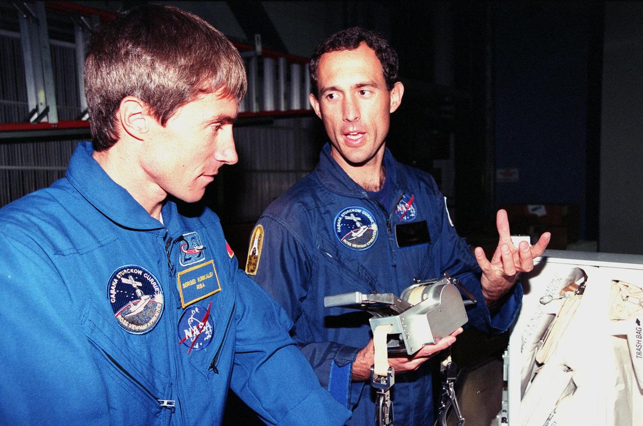
KENNEDY SPACE CENTER, FLA. -- Inside the Orbiter Processing Facility Bay 1, STS-88 Mission Specialists Sergei Krikalev (left), a Russian cosmonaut; and James H. Newman look over equipment for their upcoming flight. The STS-88 crew members are participating in a Crew Equipment Interface Test (CEIT), familiarizing themselves with the orbiter's midbody and crew compartments. Targeted for liftoff on Dec. 3, 1998, STS-88 will be the first Space Shuttle launch for assembly of the International Space Station (ISS). The primary payload is the Unity connecting module which will be mated to the Russian-built Zarya control module, expected to be already on orbit after a November launch from Russia. The first major U.S.-built component of ISS, Unity will serve as a connecting passageway to living and working areas of the space station. Unity has two attached pressurized mating adapters (PMAs) and one stowage rack installed inside. PMA-1 provides the permanent connection point between Unity and Zarya; PMA-2 will serve as a Space Shuttle docking port. Zarya is a self-supporting active vehicle, providing propulsive control capability and power during the early assembly stages. It also has fuel storage capability