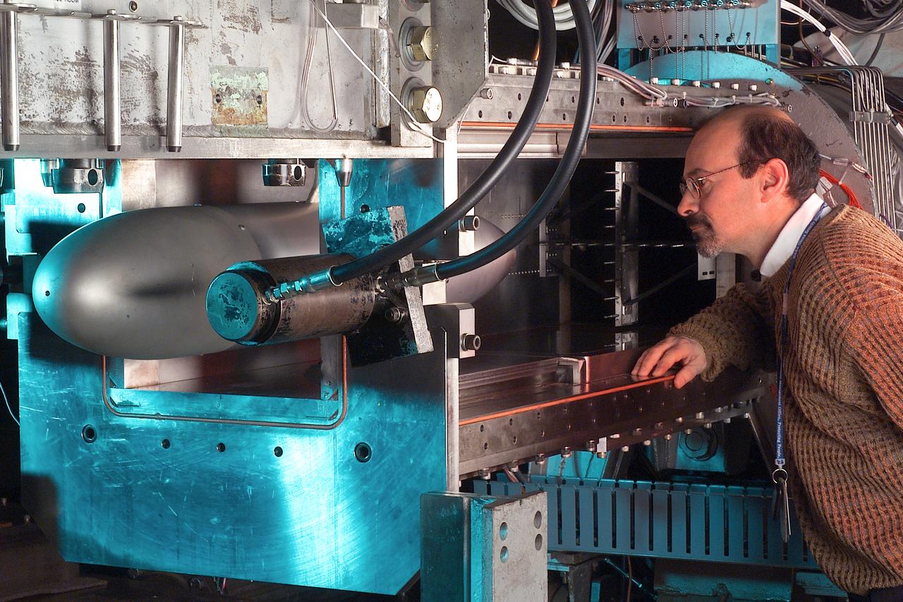
A researcher stands next to the Pulsed Ejector Wave Propagation Test Rig in an opened section of the 1'x1' Supersonic Wind Tunnel at NASA Glenn Research Center.
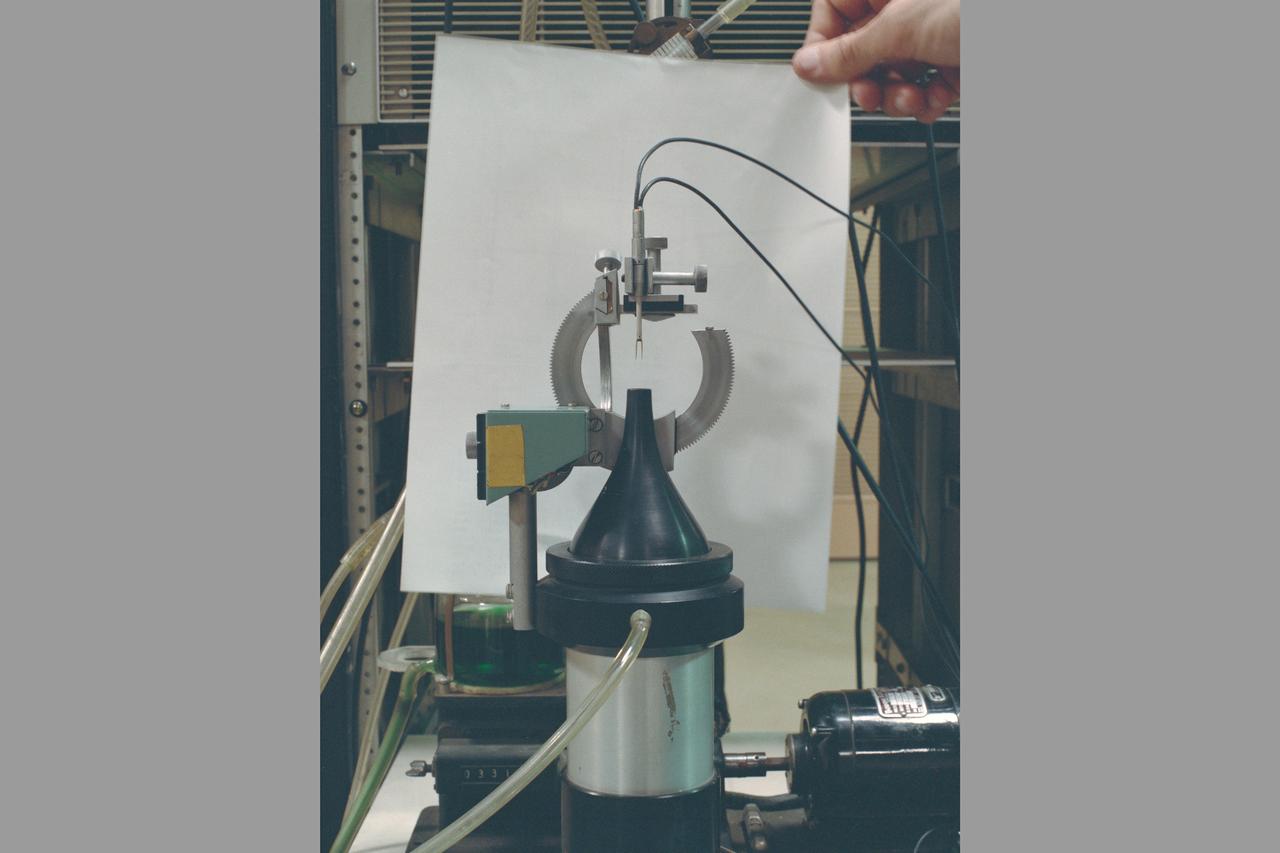
Ejector System in FML (Fluid Mechanics Lab)
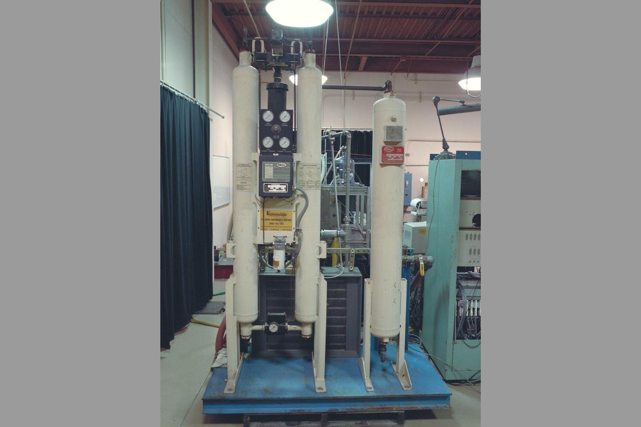
Ejector System in FML (Fluid Mechanics Lab)
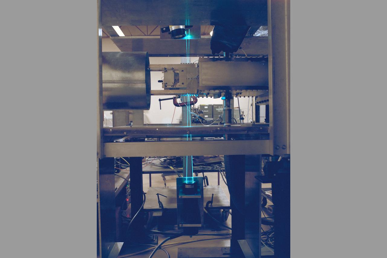
Ejector System in FML (Fluid Mechanics Lab)
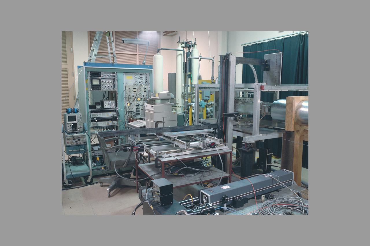
Ejector System in FML (Fluid Mechanics Lab)
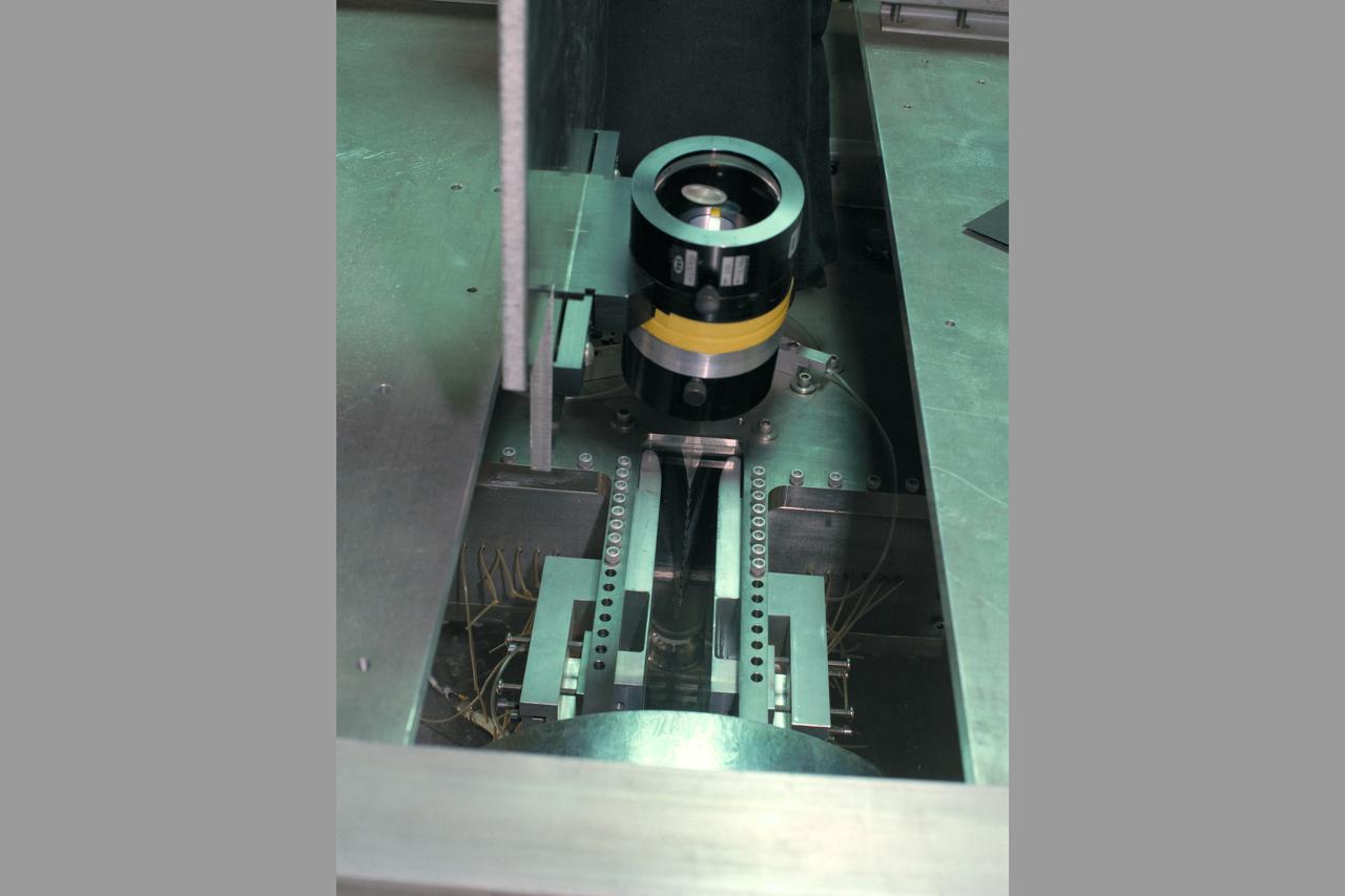
Ejector System in FML (Fluid Mechanics Lab)
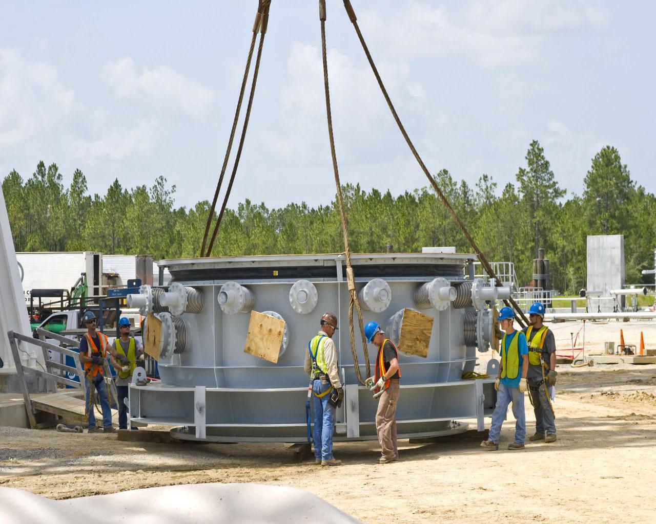
Work on the A-3 Test Stand at Stennis Space Center took a step forward in July with delivery of the first-stage steam ejector July 13. Stennis employees are shown preparing the ejector to be lifted into place on the test stand. When activated in 2012, the A-3 Test Stand will allow operators to test rocket engines at simulated altitudes of 100,000 feet, a critical feature for next-generation engines that will take humans beyond low-Earth orbit once more.
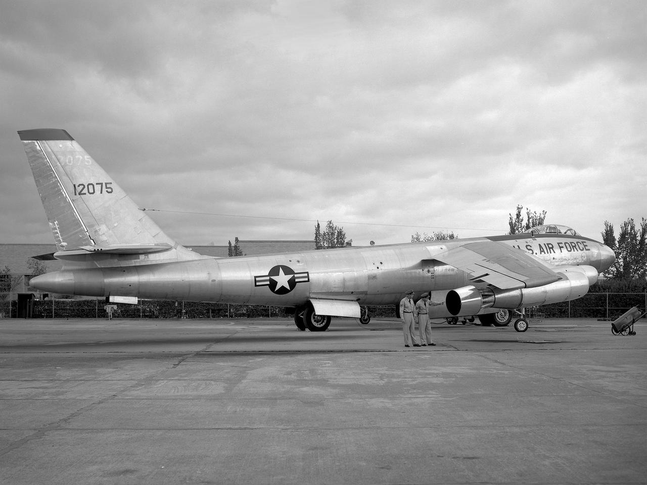
A Boeing B-47 Stratojet bomber with a noise-reducing ejector on its engine at the 1957 Inspection of the National Advisory Committee for Aeronautics (NACA) Lewis Flight Propulsion Laboratory. Representatives from the military, aeronautical industry, universities, and the press were invited to the laboratory to be briefed on the NACA’s latest research efforts and tour the state- of- the- art test facilities. Over 1700 people visited the NACA Lewis in Cleveland, Ohio during October 7 - 10, 1957. By the mid-1950s, the aircraft industry was close to introducing jet airliners to the nation’s airways. The noise produced by the large jet engines, however, would pose a considerable problem for communities near airports. This problem was demonstrated at the 1957 Inspection by an NACA Lewis researcher who played longplay (LP) audio records of military jet engines for an audience. Tests showed that the source of the loudest noise was not the engine itself, but the mixing of the engine’s exhaust with the surrounding air in the atmosphere. The pressures resulting from this turbulence produced sound waves. One of Lewis’ first studies sought to design an exhaust nozzle that reduced the turbulence. A Pratt and Whitney J57 was tested in the Altitude Wind Tunnel with many of these nozzle configurations from January to May 1957. Researchers found that the various nozzle types did reduce the noise levels but also reduced the aircraft’s thrust. Afterwards, they determined that the addition of an NACA-developed ejector reduced the noise levels without diminishing thrust.
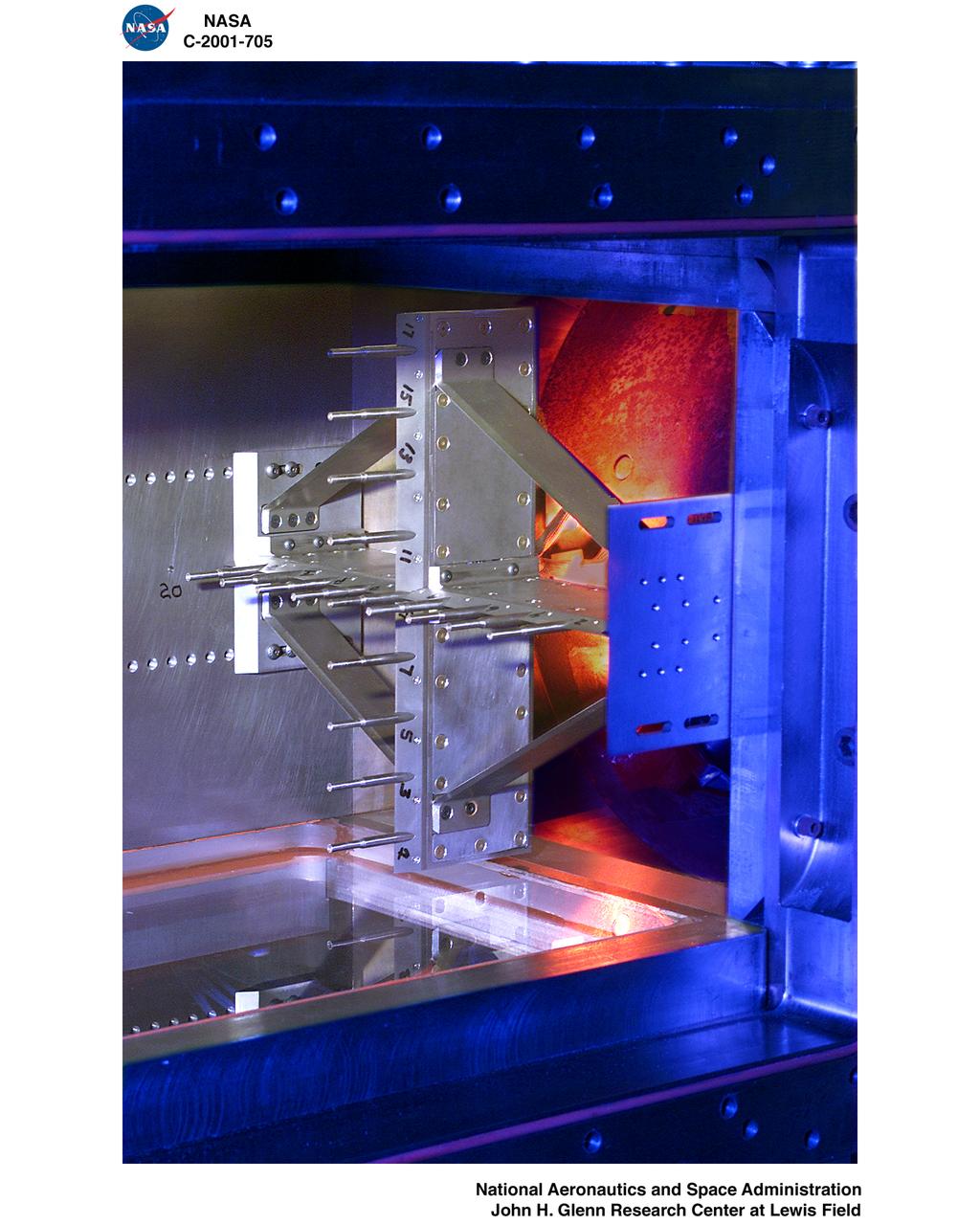
PULSED EJECTOR WAVE PROPAGATION TEST RIG
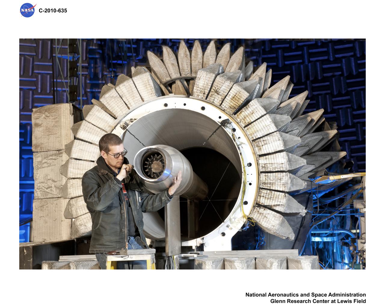
New testing is underway in the Aero-Acoustic Propulsion Laboratory (AAPL) at NASA's Glenn Research Center. The research focuses on a model called the Highly Variable Cycle Exhaust System -- a 0.17 scale model of an exhaust system that will operate at subsonic, transonic and supersonic exhaust speeds in a future supersonic business jet. The model features ejector doors used at different angles. Researchers are investigating the impact of these ejectors on the resulting acoustic radiation. Here, Steven Sedensky, a mechanical engineer with Jacobs Sverdrup, takes measurements of the ejector door positions.
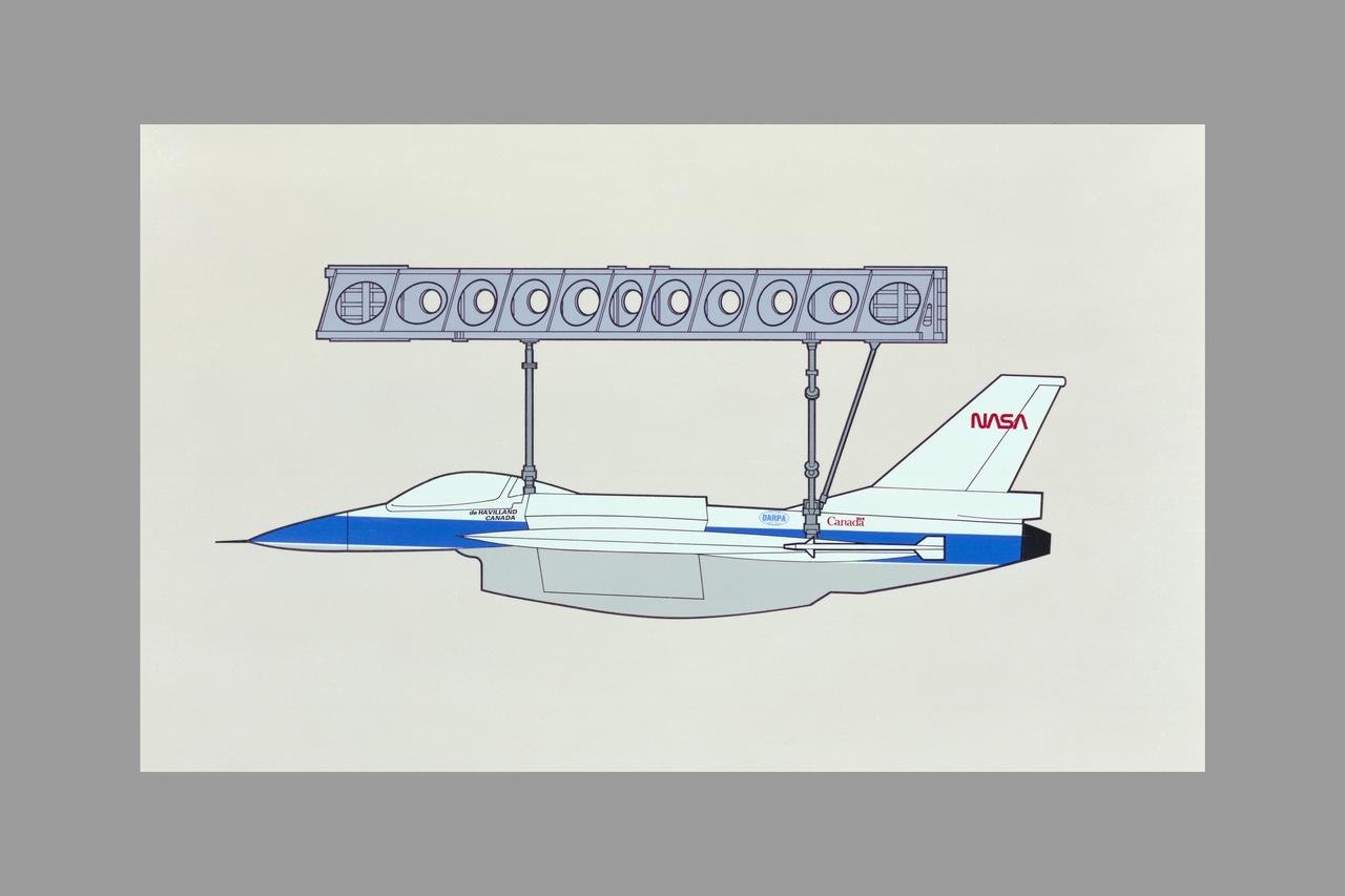
Drawing DARPA Ejector fighter model (deHavilland/Canada/NASA) E-7
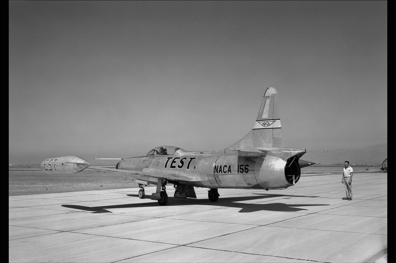
LOCKHEED F-94C #156 AIRPLANE. COOLING AIR EJECTOR on NACA Ames Flight Line
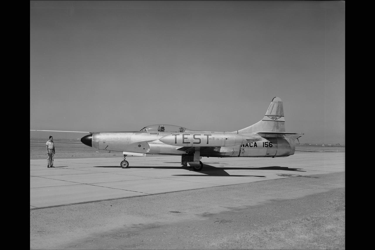
LOCKHEED F-94C #156 AIRPLANE. COOLING AIR EJECTOR on NACA Ames Flight Line
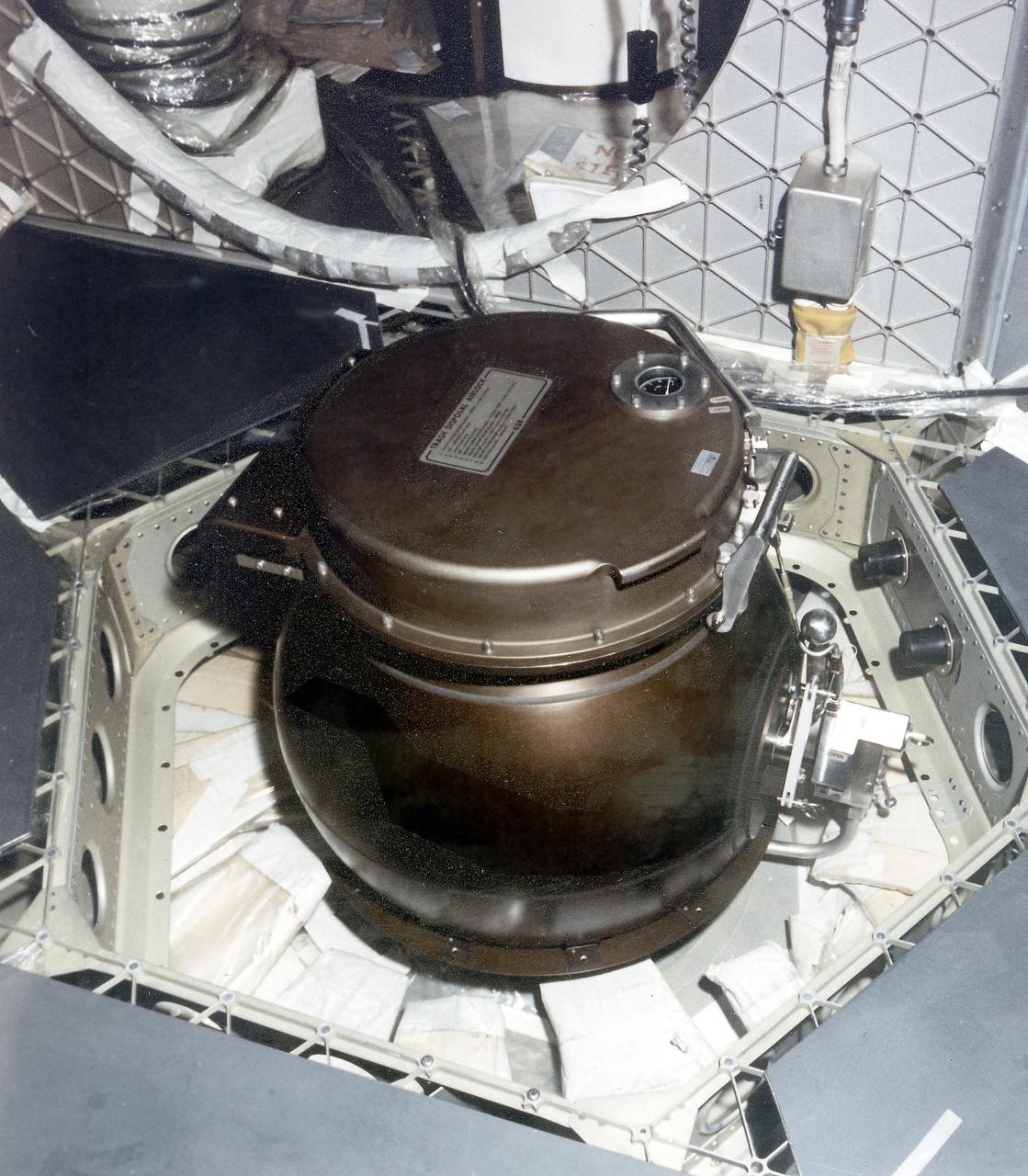
This is a close-up photograph of the Orbital Workshop (OWS) trash disposal airlock located on the floor of the lower level of the OWS. It provided a means of passing trash from the pressurized habitable area into the unpressurized waste tank. The crewman opened a valve which brought the airlock to the same pressure as that within the workshop. He then opened the lid, placed the bagged trash inside, closed the lid and locked it. By turning the valve handle, he reduced the pressure within the airlock until it reached the vacuum of the waste tank. The crewman then operated an ejector handle that caused a scissors-type mechanism to push the bagged trash from the airlock into the tank.
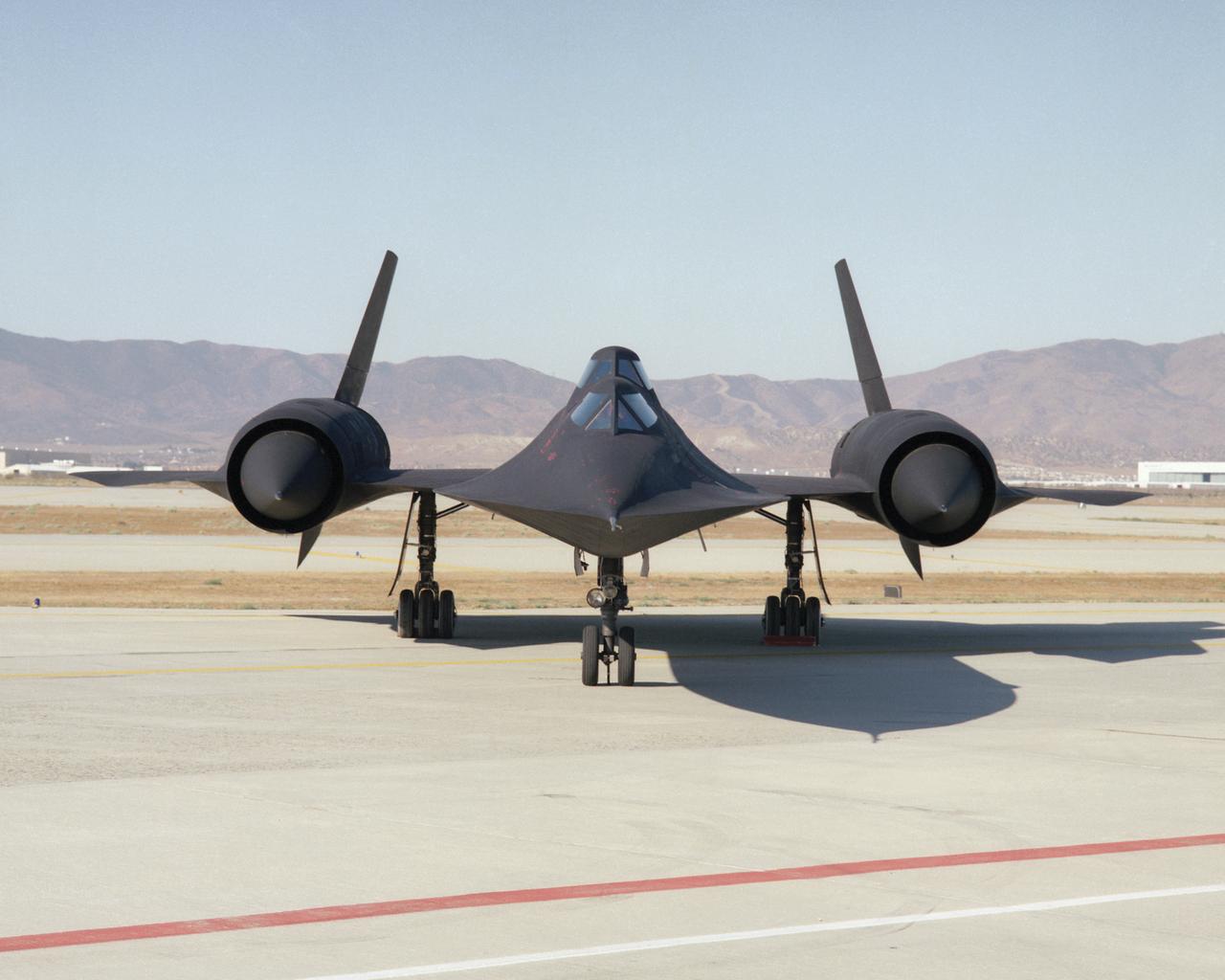
This photo shows a head-on view of NASA's SR-71B, used for pilot proficiency and training, on the ramp at the Air Force's Plant 42 in Palmdale, California, shortly before delivery to the Ames-Dryden Flight Research Facility (later, Dryden Flight Research Center) at Edwards, California. NASA operated two of these unique aircraft, an SR-71A, for high-speed, high altitude research, and this SR- 71B pilot trainer for most of the decade of the 1990s. The "B" model is special because of its raised rear cockpit, which provided a second pilot position so a trainer and an experienced pilot could both see what was going on during flights. The SR-71 was designed and built by the Lockheed Skunk Works, now the Lockheed Martin Skunk Works. Studies have shown that less than 20 percent of the total thrust used to fly at Mach 3 is produced by the basic engine itself. The balance of the total thrust is produced by the unique design of the engine inlet and "moveable spike" system at the front of the engine nacelles, and by the ejector nozzles at the exhaust which burn air compressed in the engine bypass system. Data from the SR-71 high speed research program will be used to aid designers of future supersonic/hypersonic aircraft and propulsion systems, including a high speed civil transport.
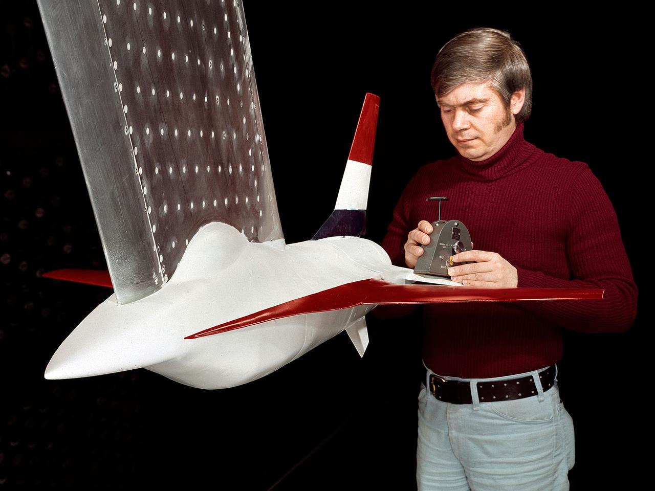
A model of the General Dynamics YF-16 Fighting Falcon in the test section of the 8- by 6-Foot Supersonic Wind Tunnel at the National Aeronautics and Space Administration (NASA) Lewis Research Center. The YF-16 was General Dynamics response to the military’s 1972 request for proposals to design a new 20,000-pound fighter jet with exceptional acceleration, turn rate, and range. The aircraft included innovative design elements to help pilots survive turns up to 9Gs, a new frameless bubble canopy, and a Pratt and Whitney 24,000-pound thrust F-100 engine. The YF-16 made its initial flight in February 1974, just six weeks before this photograph, at Edwards Air Force Base. Less than a year later, the Air Force ordered 650 of the aircraft, designated as F-16 Fighting Falcons. The March and April 1974 tests in the 8- by 6-foot tunnel analyzed the aircraft’s fixed-shroud ejector nozzle. The fixed-nozzle area limited drag, but also limited the nozzle’s internal performance. NASA researchers identified and assessed aerodynamic and aerodynamic-propulsion interaction uncertainties associated the prototype concept. YF-16 models were also tested extensively in the 11- by 11-Foot Transonic Wind Tunnel and 9- by 7-Foot Supersonic Wind Tunnel at Ames Research Center and the 12-Foot Pressure Wind Tunnel at Langley Research Center.
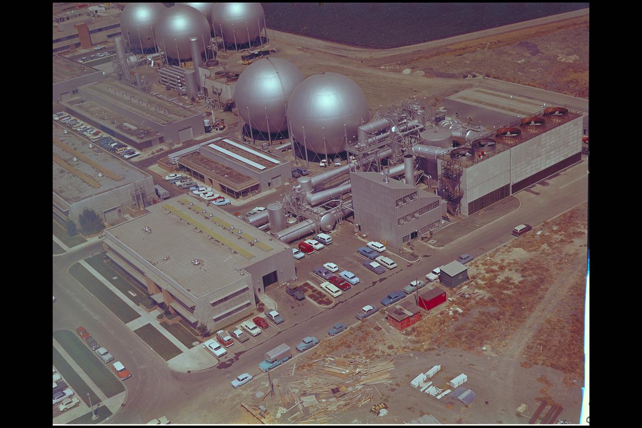
Aerial view of Gasdynamics facility in 1964 and the 20 inch helium tunnel Part of the Thermal Protection Laboratory used to research materials for heat shield applications and for aerodynamic heating and materials studies of vehicles in planetary atmospheres. This laboratory is comprised of five separate facilities: an Aerodynamic Heating Tunnel, a Heat Transfer Tunnel, two Supersonic Turbulent Ducts, and a High-Power CO2 Gasdynamic Laser. All these facilities are driven by arc-heaters, with the exception of the large, combustion-type laser. The arc-heated facilities are powered by a 20 Megawatt DC power supply. Their effluent gas stream (test gases; Air, N2, He, CO2 and mixtures; flow rates from 0.05 to 5.0 lbs/sec) discharges into a five-stage stream-ejector-driven vacuum system. The vacuum system and power supply are common to the test faciities in building N-238. All of the facilities have high pressure water available at flow rates up to 4, 000 gals/min. The data obtained from these facilities are recorded on magnetic tape or oscillographs. All forms of data can be handled whether from thermo-couples, pressure cells, pyrometers, or radiometers, etc. in addition, closed circuit T. V. monitors and various film cameras are available. (operational since 1962)
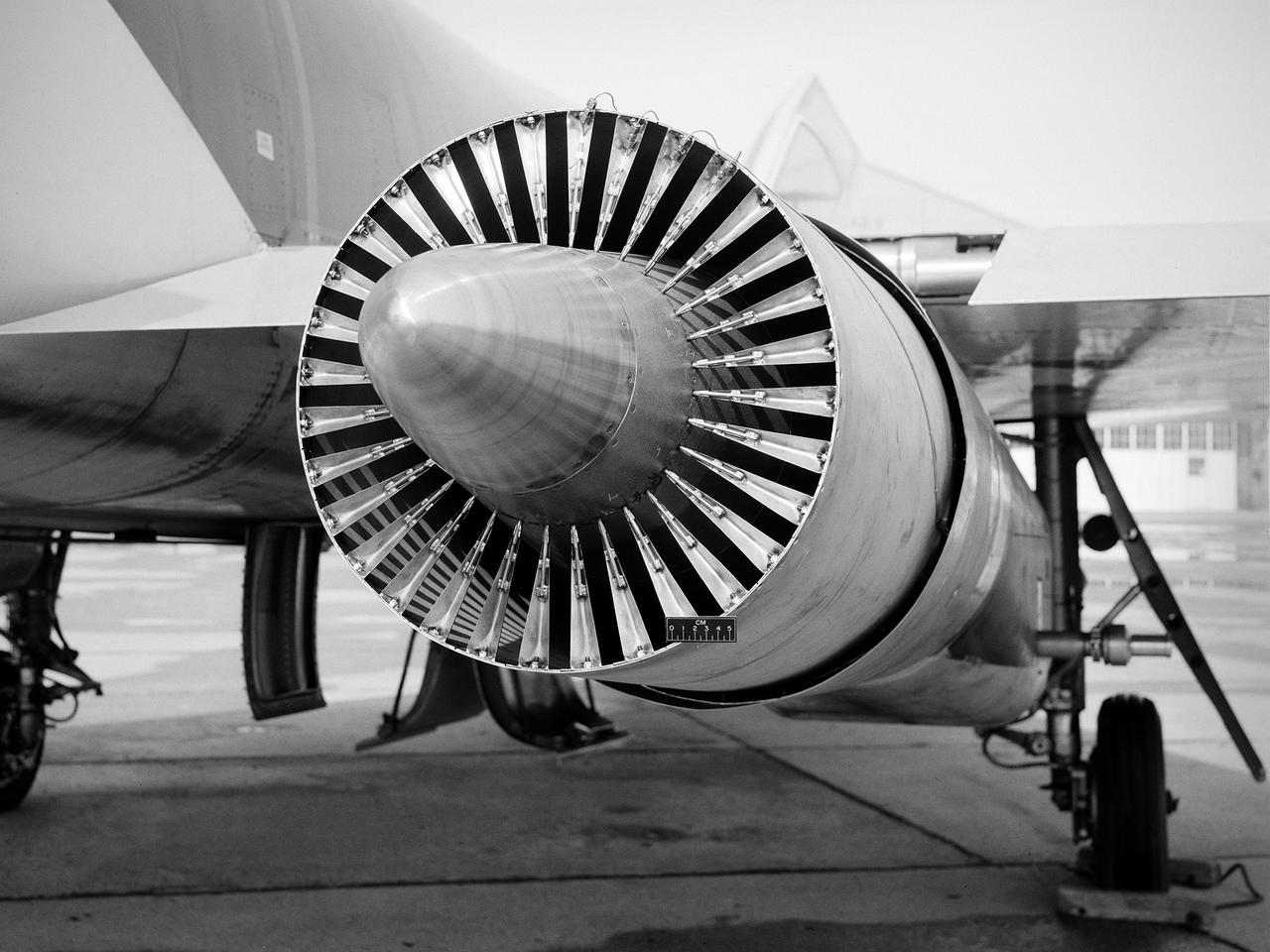
National Aeronautics and Space Administration (NASA) Convair F-106B Delta Dart with a 32-spoke nozzle installed on its General Electric J85 test engine. Lewis acquired a Delta Dart fighter in 1966 to study the components for propulsion systems that could be applied to supersonic transport aircraft at transonic speeds. The F-106B was modified with two General Electric J85-13 engines under its wings to study these components. The original test plan was expanded to include the study of boattail drag, noise reduction, and inlets. From February to July 1971 the modified F-106B was used to study different ejector nozzles. Researchers conducted both acoustic and aerodynamic tests on the ground and in flight. Several models were created to test different suppression methods. NASA Lewis’ conical nozzle was used as the baseline configuration. Flightline and sideline microphones were set up on the ground. The F-106B would idle its own engine and buzz the recording station from an altitude of 300 feet at Mach 0.4 with the test engines firing. Researchers found that the suppression of the perceived noise level was usually lower during flight than the researchers had statistically predicted. The 64 and 32-spoke nozzles performed well in actual flight, but the others nozzles tended to negatively affect the engine’s performance. Different speeds or angles- -of-attack sometimes changed the noise levels. In the end, no general conclusions could be applied to all the nozzles.
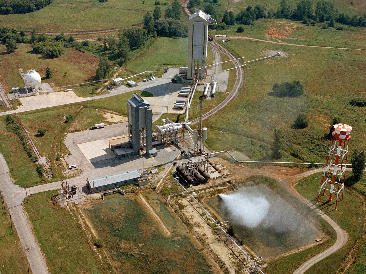
Operation of the High Energy Rocket Engine Research Facility (B-1), left, and Nuclear Rocket Dynamics and Control Facility (B-3) at the National Aeronautics and Space Administration’s (NASA) Plum Brook Station in Sandusky, Ohio. The test stands were constructed in the early 1960s to test full-scale liquid hydrogen fuel systems in simulated altitude conditions. Over the next decade each stand was used for two major series of liquid hydrogen rocket tests: the Nuclear Engine for Rocket Vehicle Application (NERVA) and the Centaur second-stage rocket program. The different components of these rocket engines could be studied under flight conditions and adjusted without having to fire the engine. Once the preliminary studies were complete, the entire engine could be fired in larger facilities. The test stands were vertical towers with cryogenic fuel and steam ejector systems. B-1 was 135 feet tall, and B-3 was 210 feet tall. Each test stand had several levels, a test section, and ground floor shop areas. The test stands relied on an array of support buildings to conduct their tests, including a control building, steam exhaust system, and fuel storage and pumping facilities. A large steam-powered altitude exhaust system reduced the pressure at the exhaust nozzle exit of each test stand. This allowed B-1 and B-3 to test turbopump performance in conditions that matched the altitudes of space.
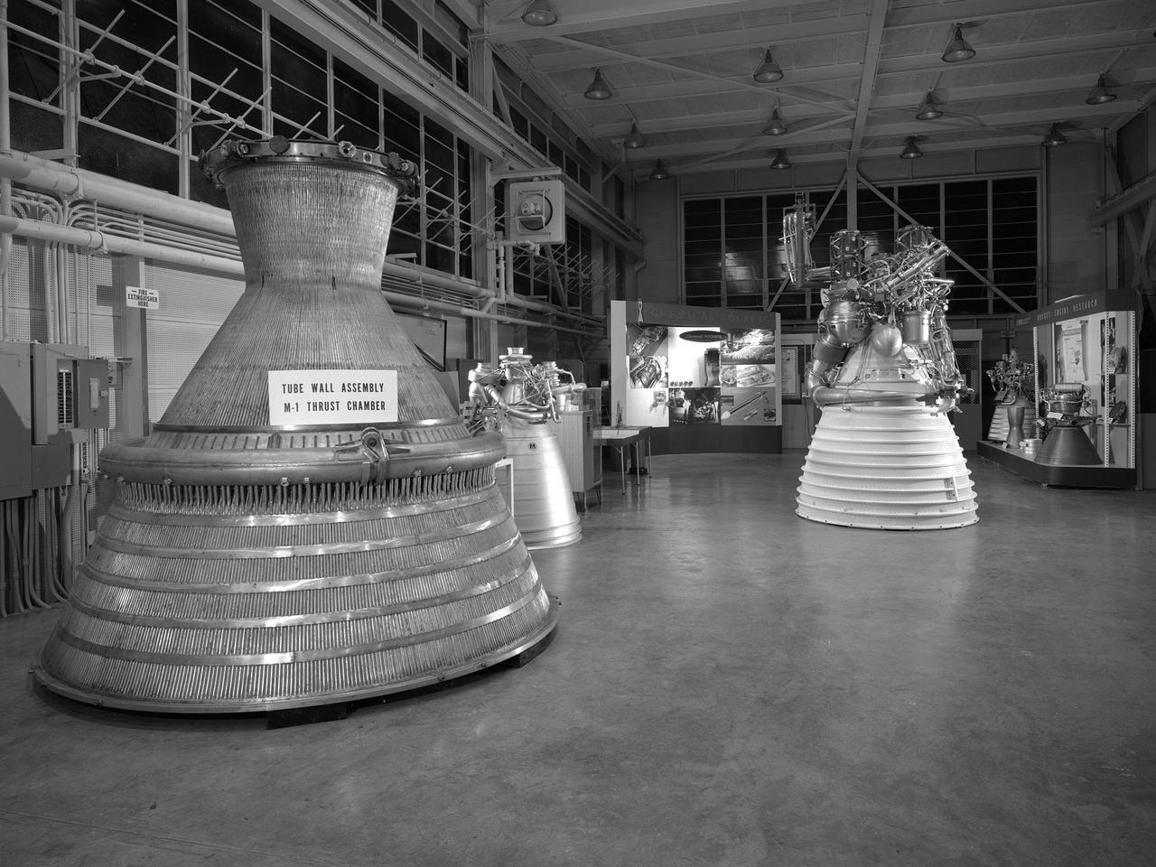
An array of rocket engines displayed in the Propulsion Systems Laboratory for the 1966 Inspection held at the National Aeronautics and Space Administration (NASA) Lewis Research Center. Lewis engineers had been working on chemical, nuclear, and solid rocket engines throughout the 1960s. The engines on display are from left to right: two scale models of the Aerojet M-1, a Rocketdyne J-2, a Pratt and Whitney RL-10, and a Rocketdyne throttleable engine. Also on display are several ejector plates and nozzles. The Chemical Rocket Division resolved issues such as combustion instability and screech, and improved operation of cooling systems and turbopumps. The 1.5-million pound thrust M-1 engine was the largest hydrogen-fueled rocket engine ever created. It was a joint project between NASA Lewis and Aerojet-General. Although much larger in size, the M-1 used technology developed for the RL-10 and J-2. The M-1 program was cancelled in late 1965 due to budget cuts and the lack of a post-Apollo mission. The October 1966 Inspection was the culmination of almost a year of events held to mark the centers’ 25th anniversary. The three‐day Inspection, Lewis’ first since 1957, drew 2000 business, industry, and government executives and included an employee open house. The visitors witnessed presentations at the major facilities and viewed the Gemini VII spacecraft, a Centaur rocket, and other displays in the hangar. In addition, Lewis’ newest facility, the Zero Gravity Facility, was shown off for the first time.
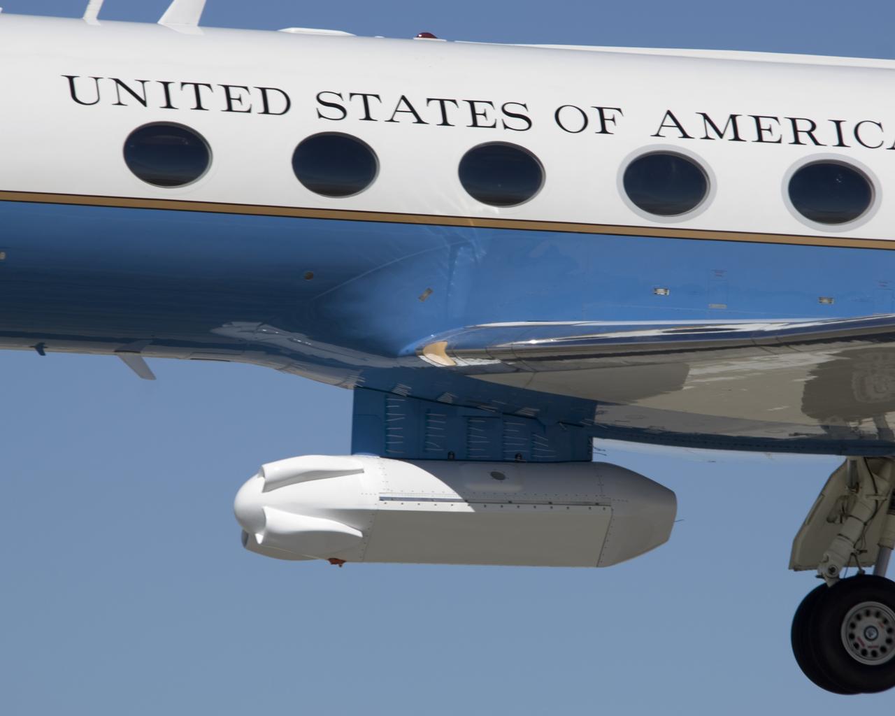
The synthetic aperture radar pod developed by JPL is slung beneath NASA's Gulfstream-III research testbed during flight tests.
An eight-foot-long pod designed to carry a synthetic aperture radar hangs from the underbelly of NASA's Gulfstream-III research testbed.
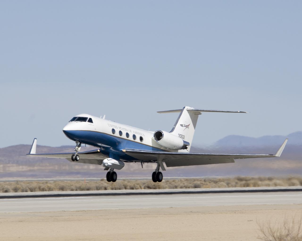
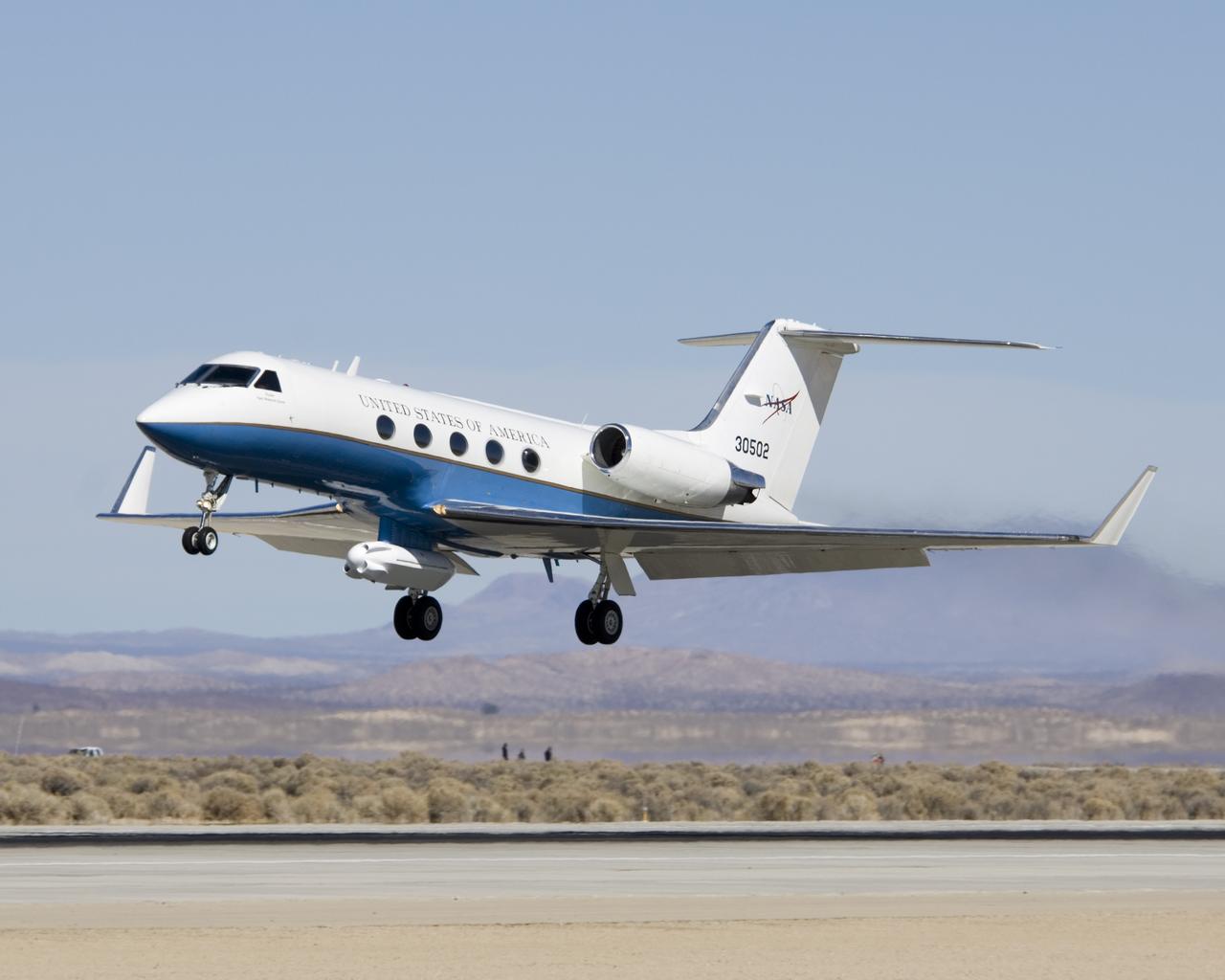
NASA's Gulfstream-III research testbed lifts off from Edwards AFB on a checkout test flight with the UAV synthetic aperture radar pod under its belly.

NASA's Gulfstream-III research testbed lifts off the Edwards AFB runway on an envelope-expansion flight test with the UAV synthetic aperture radar pod.
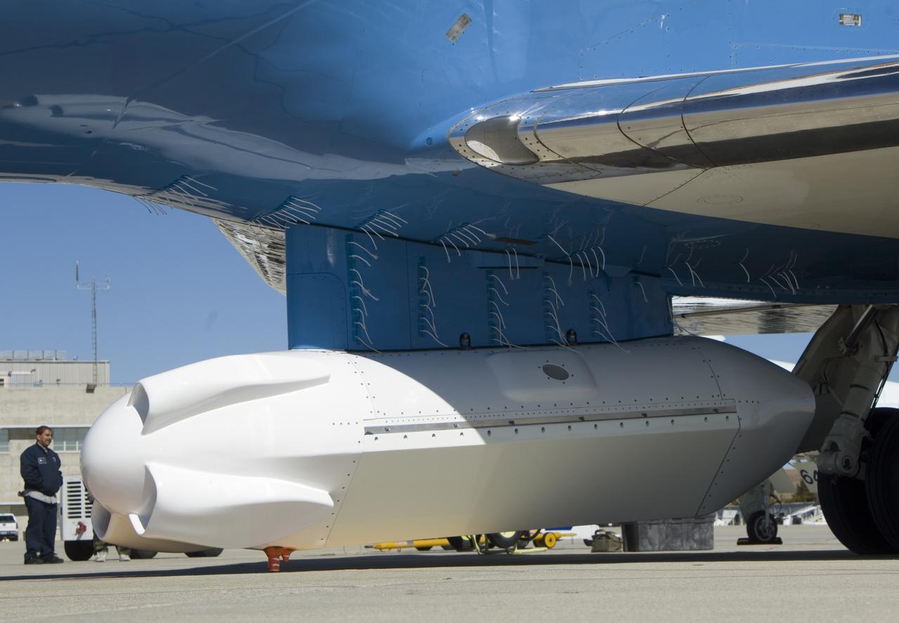
A forest of tufts are mounted on the underbelly and pylon of NASA's Gulfstream-III research aircraft to help engineers determine airflow around the UAVSAR pod.
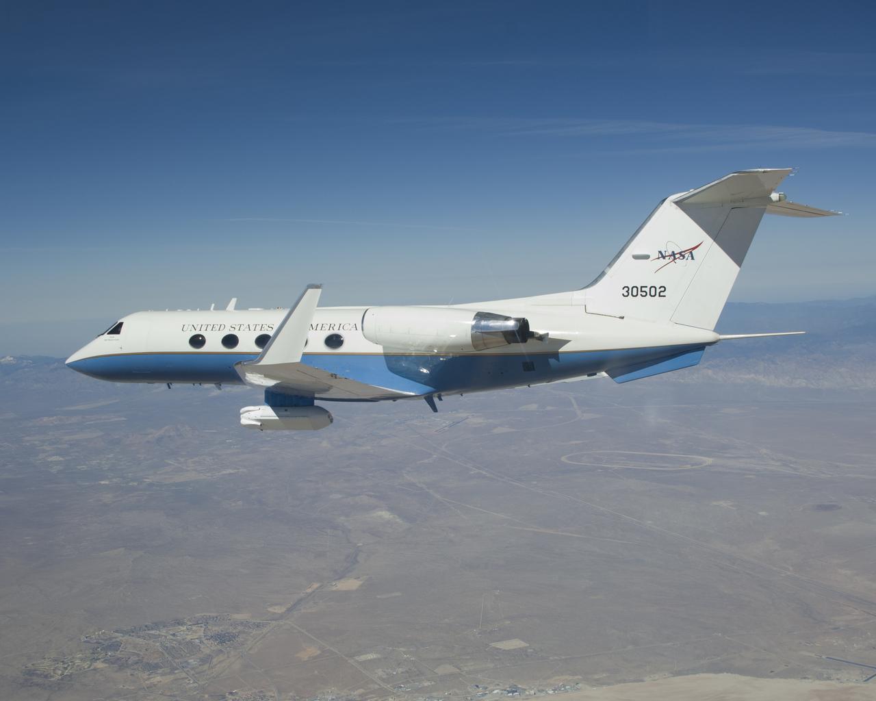
The effect of the underbelly UAVSAR pod on the aerodynamics of NASA's Gulfstream-III research aircraft was evaluated during several check flights in early 2007.
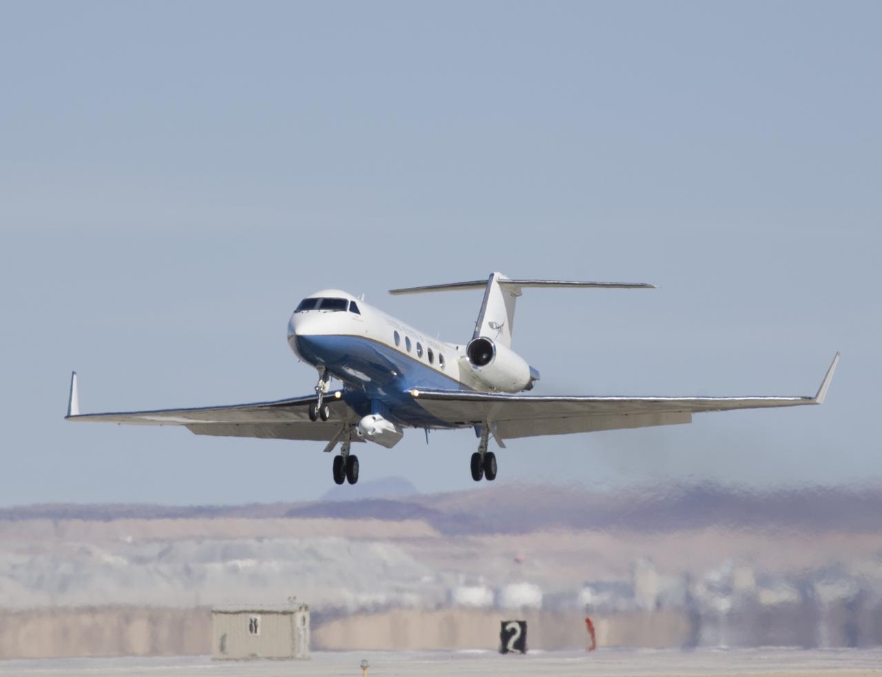
Shimmering heat waves trail behind NASA's Gulfstream-III research aircraft as it departs the Edwards AFB runway on a UAVSAR pod checkout test flight.
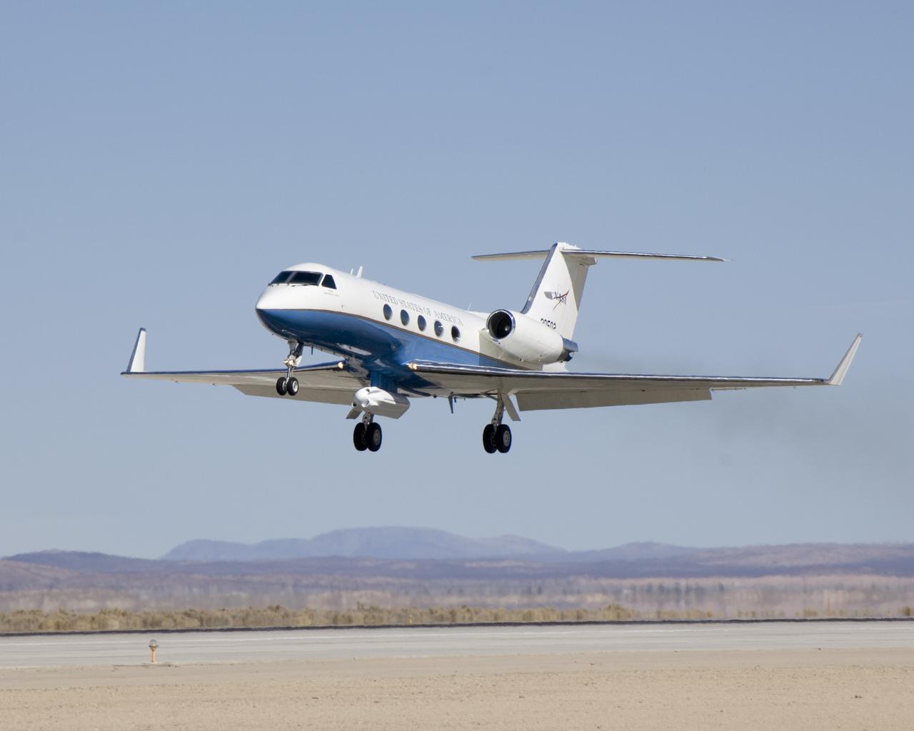
A half-dozen test flights in early 2007 evaluated the aerodynamic effect of the UAVSAR pod on the performance of NASA's Gulfstream-III research testbed.
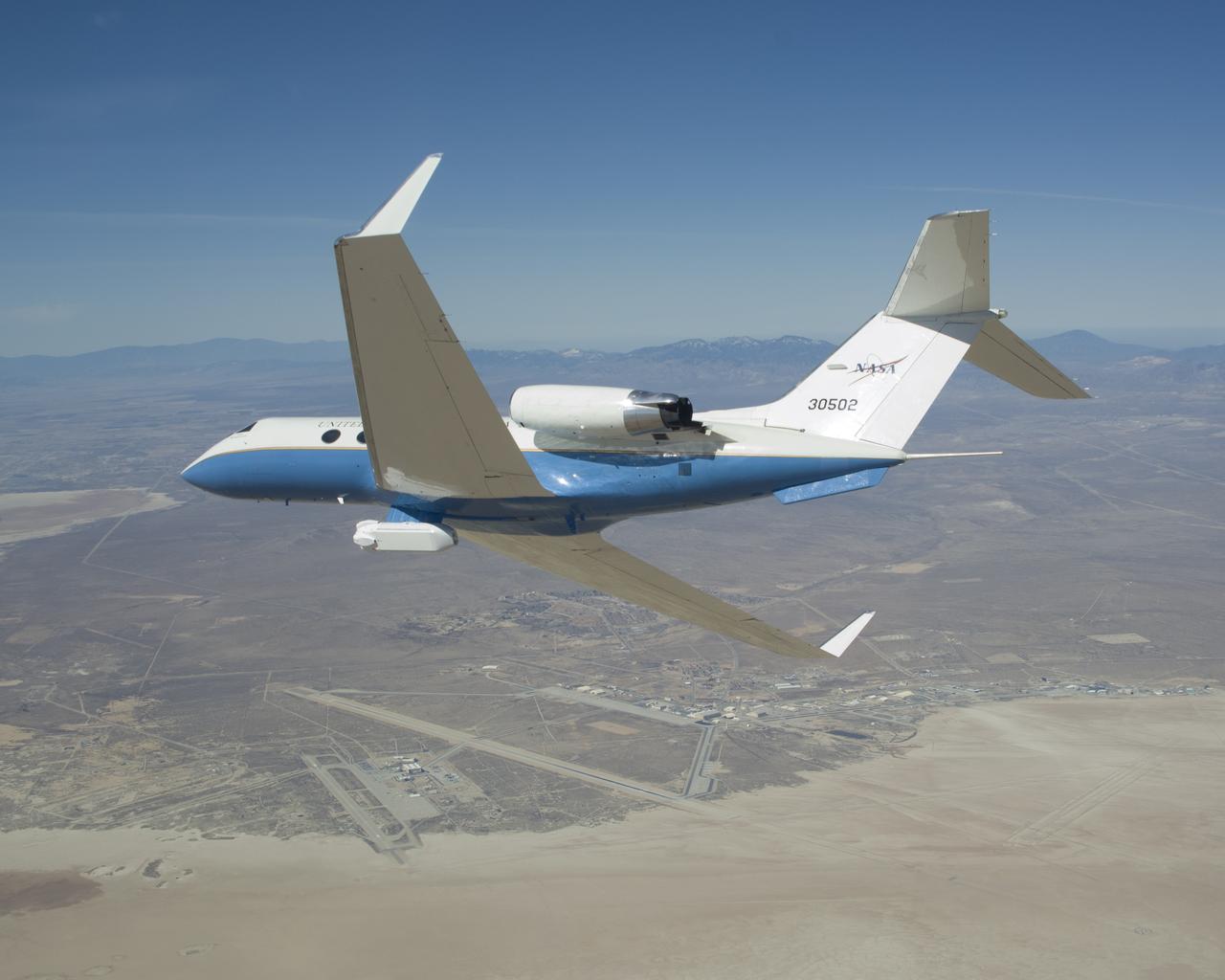
The UAVSAR underbelly pod is in clear view as NASA's Gulfstream-III research aircraft banks away over Edwards AFB during aerodynamic clearance flights.