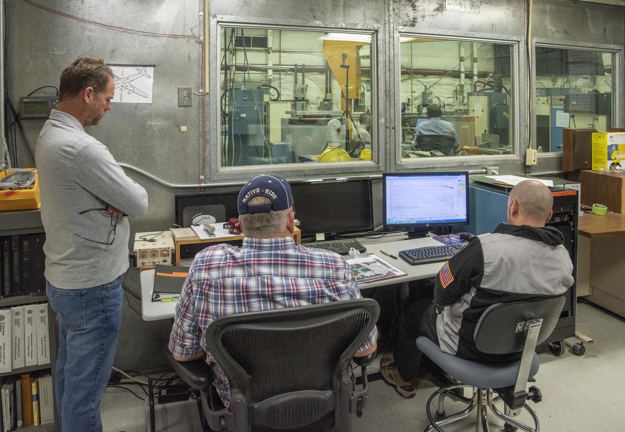
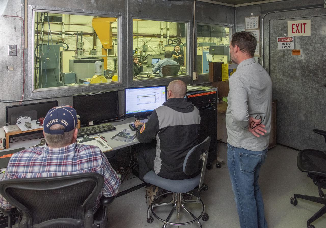
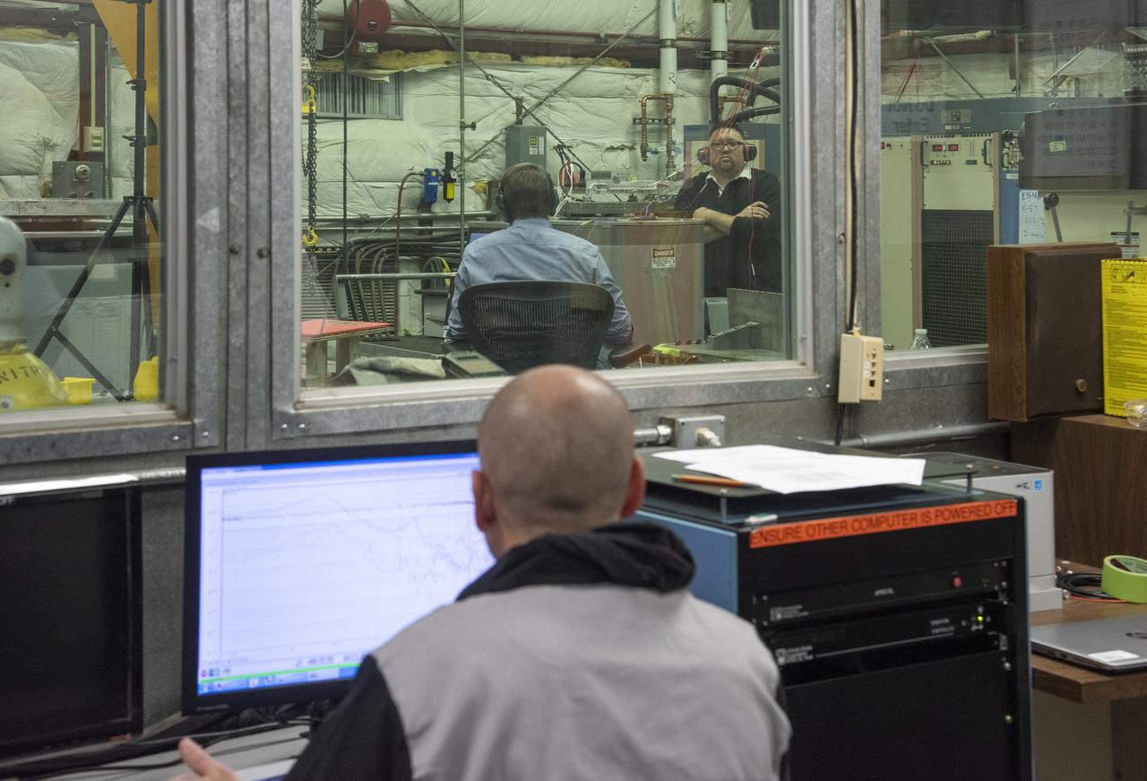
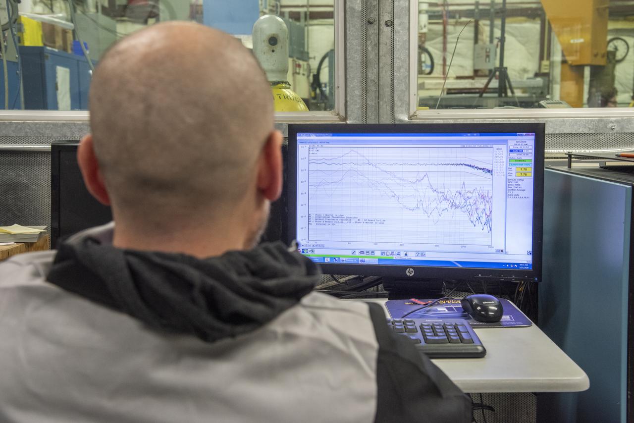
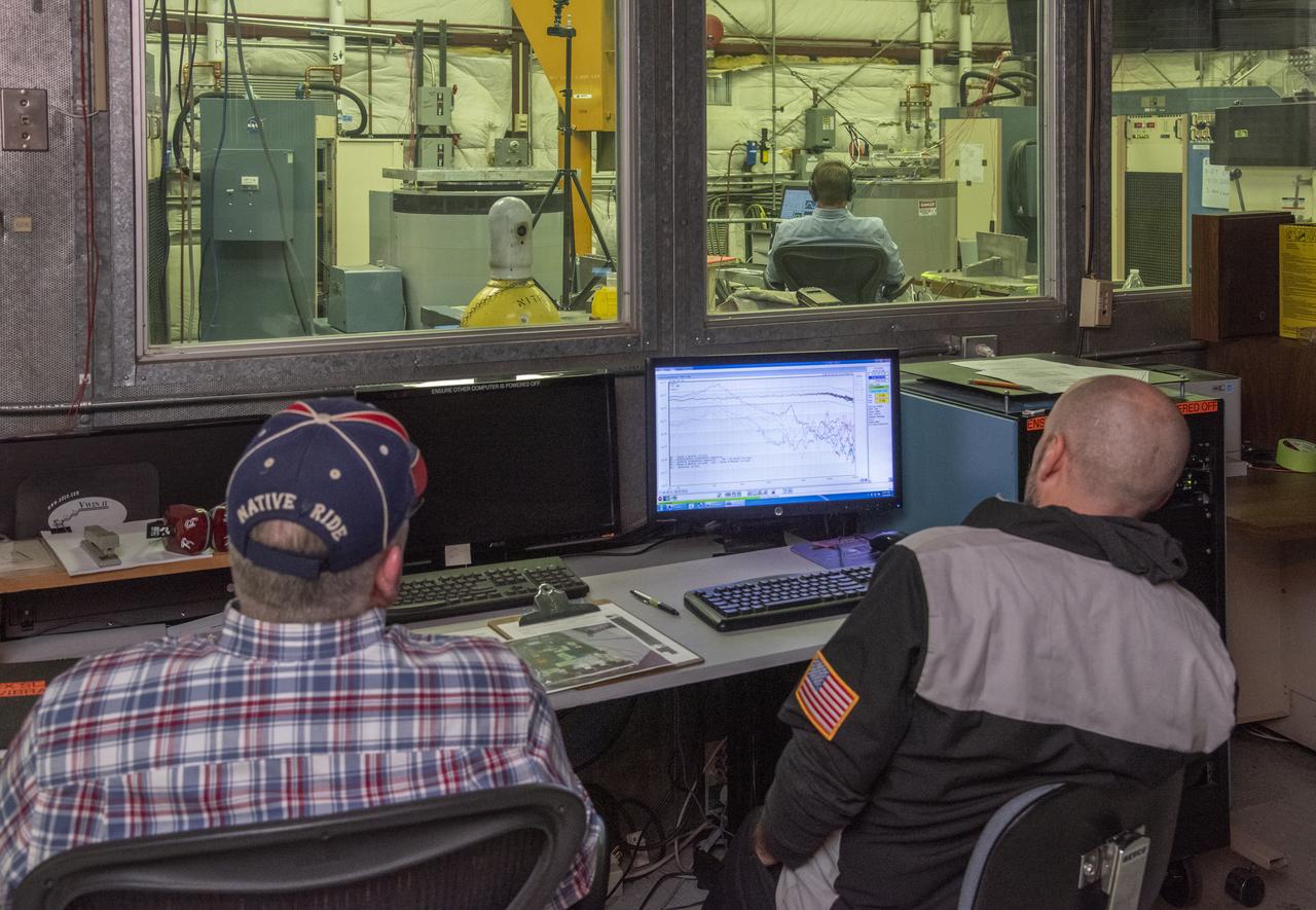
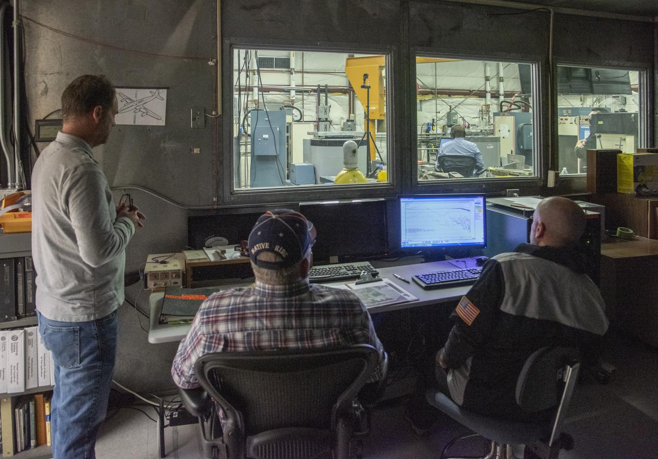
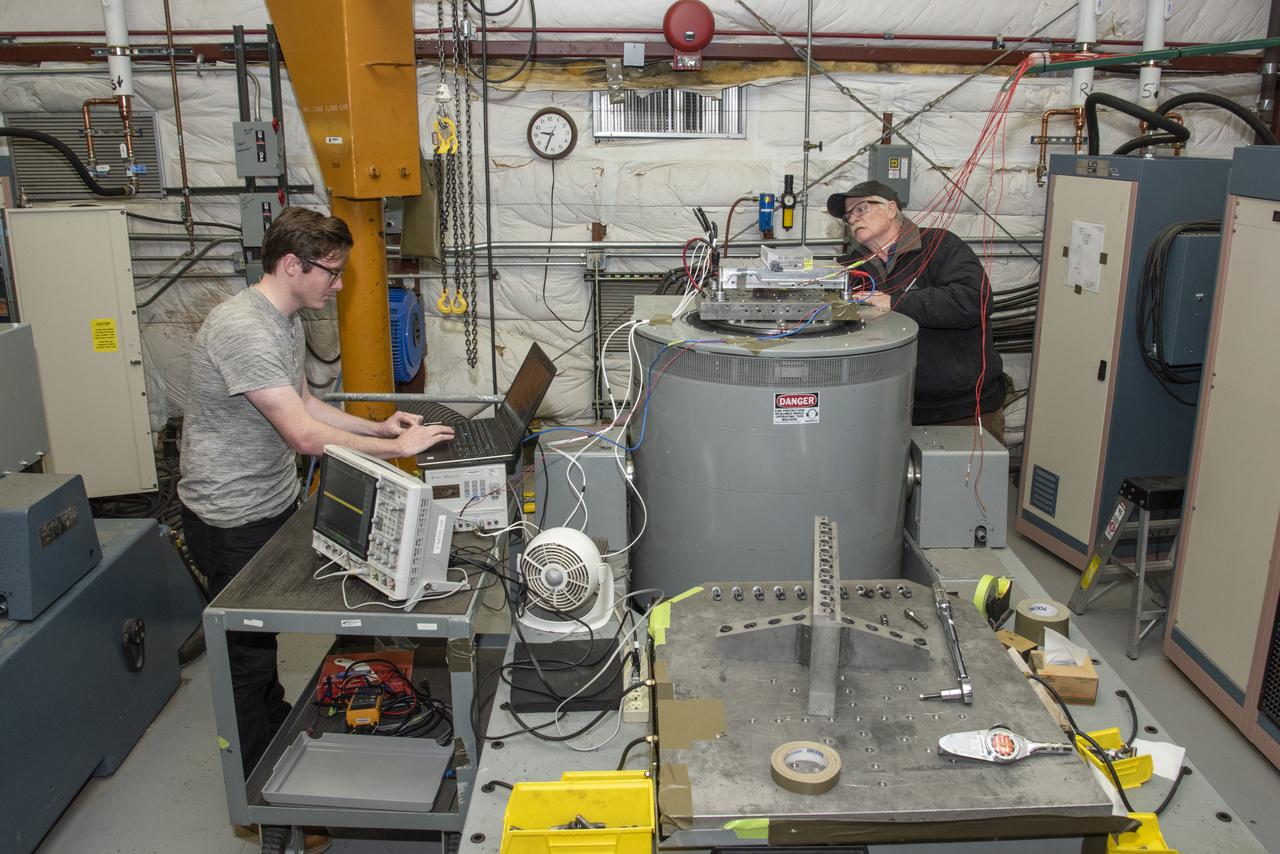
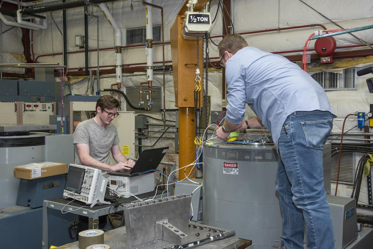
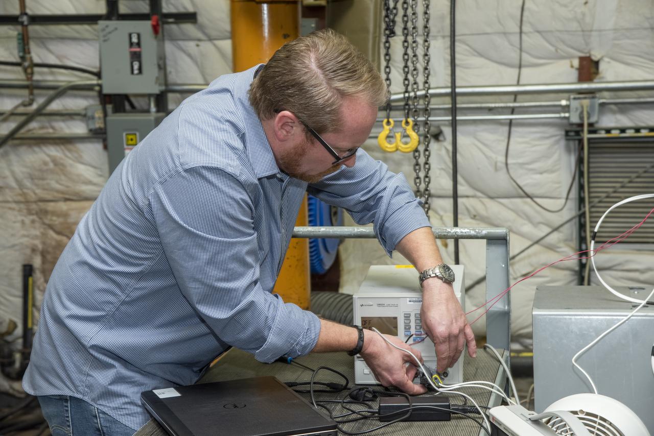
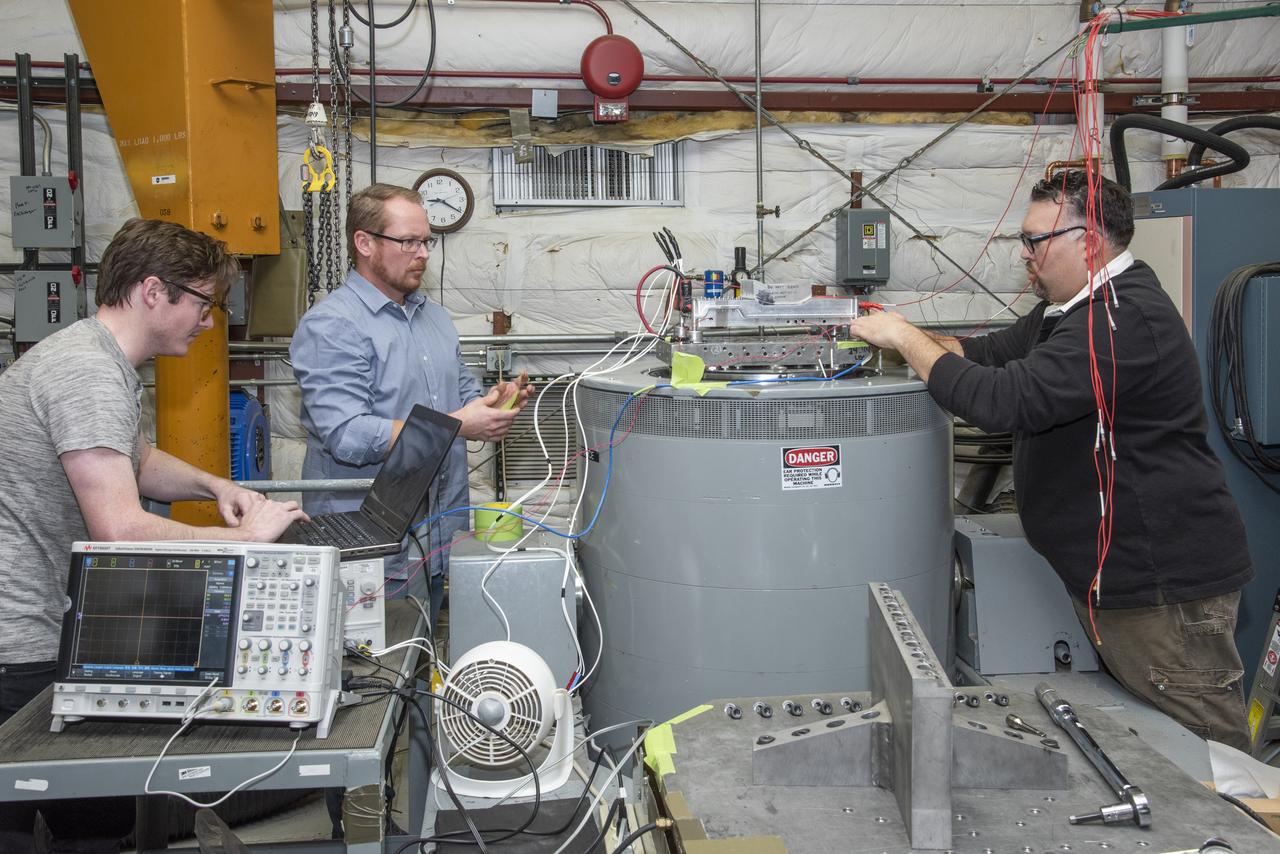
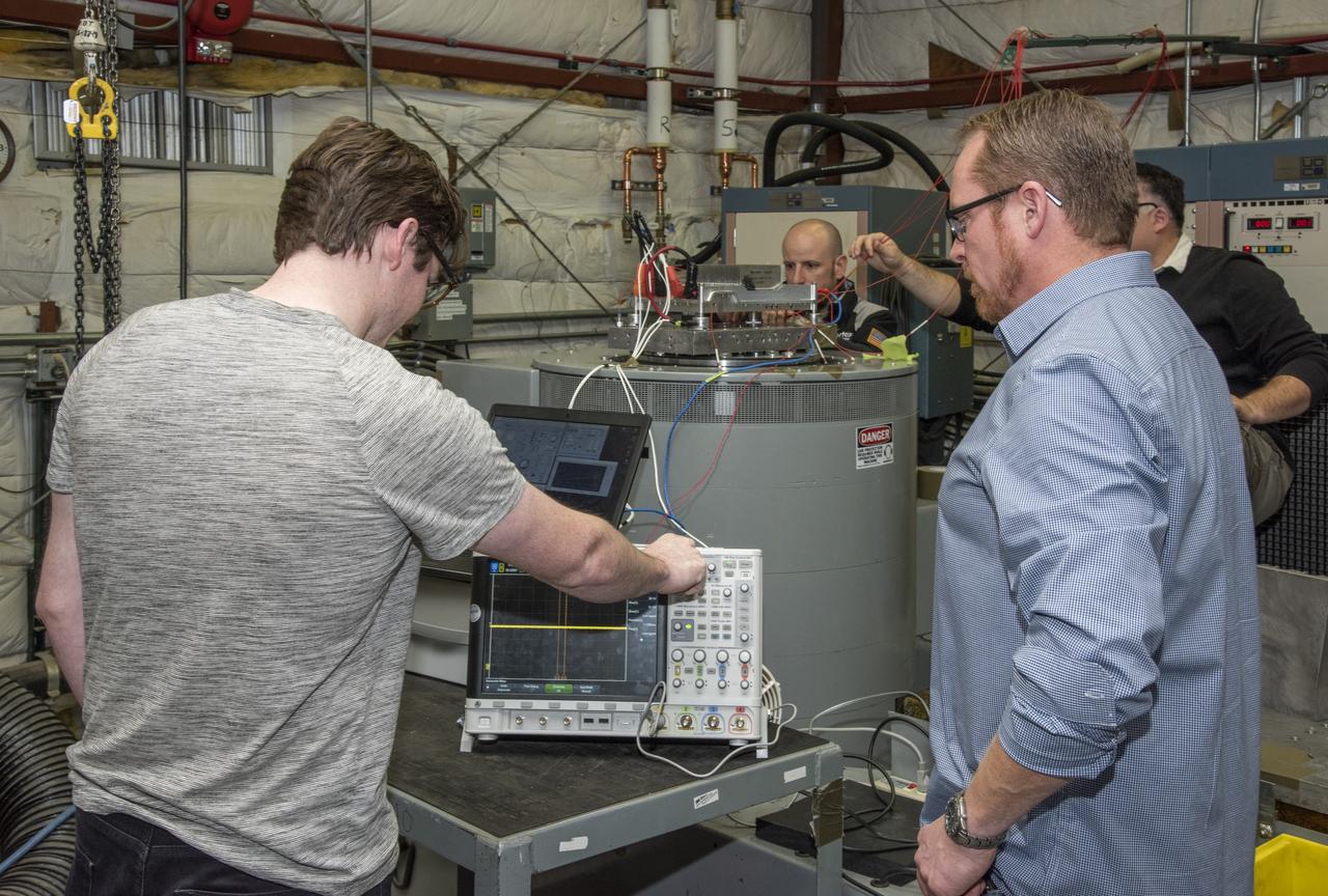
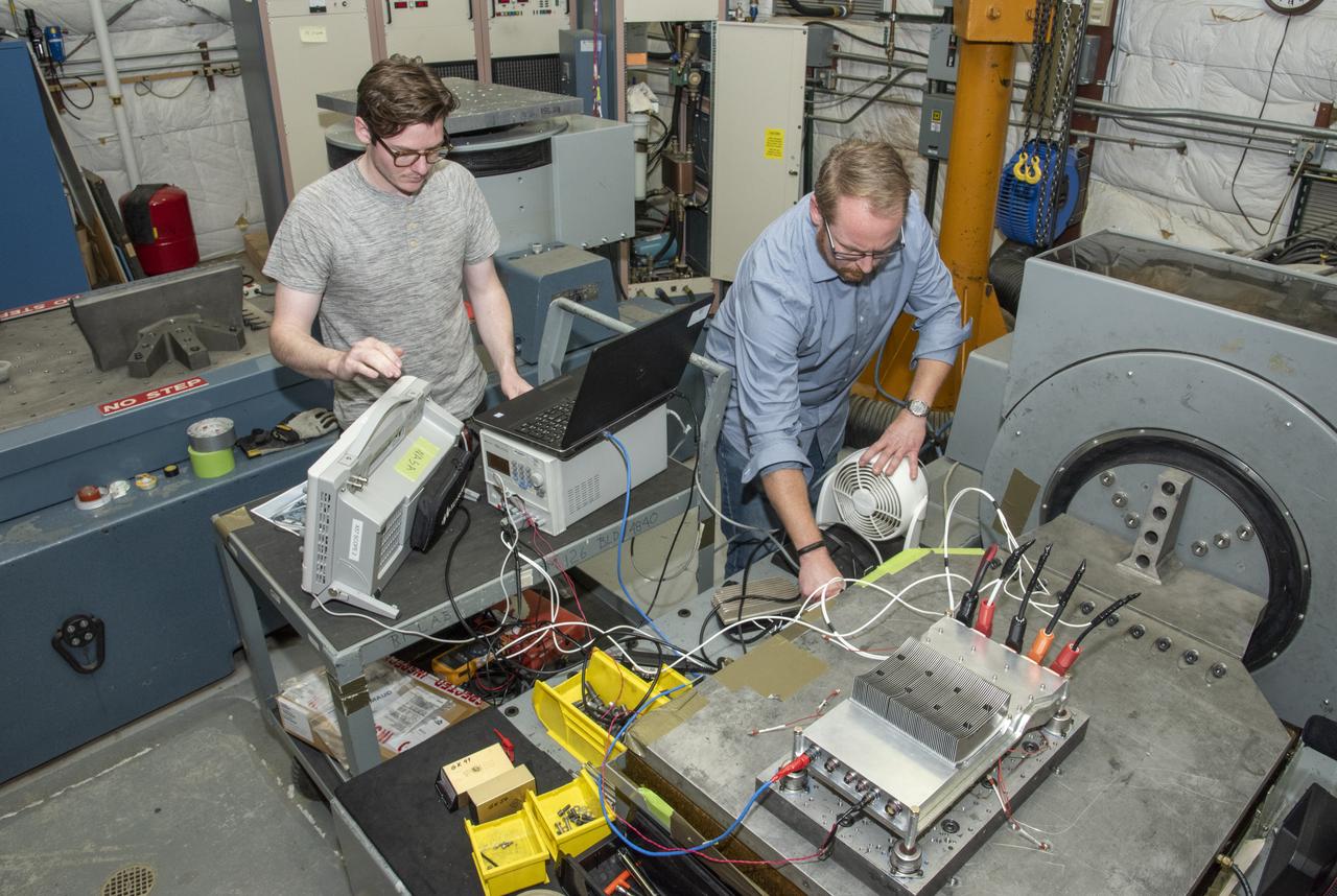
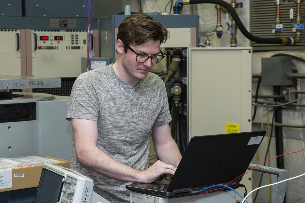
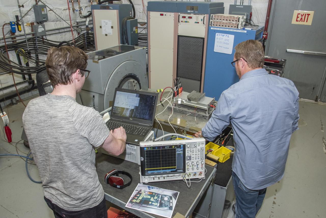
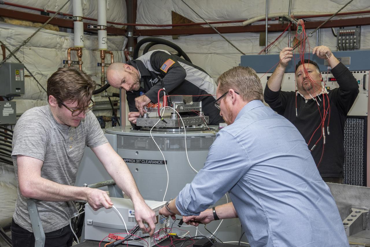
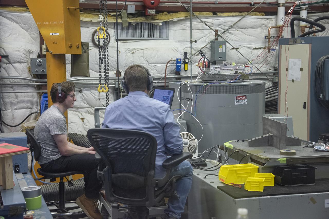
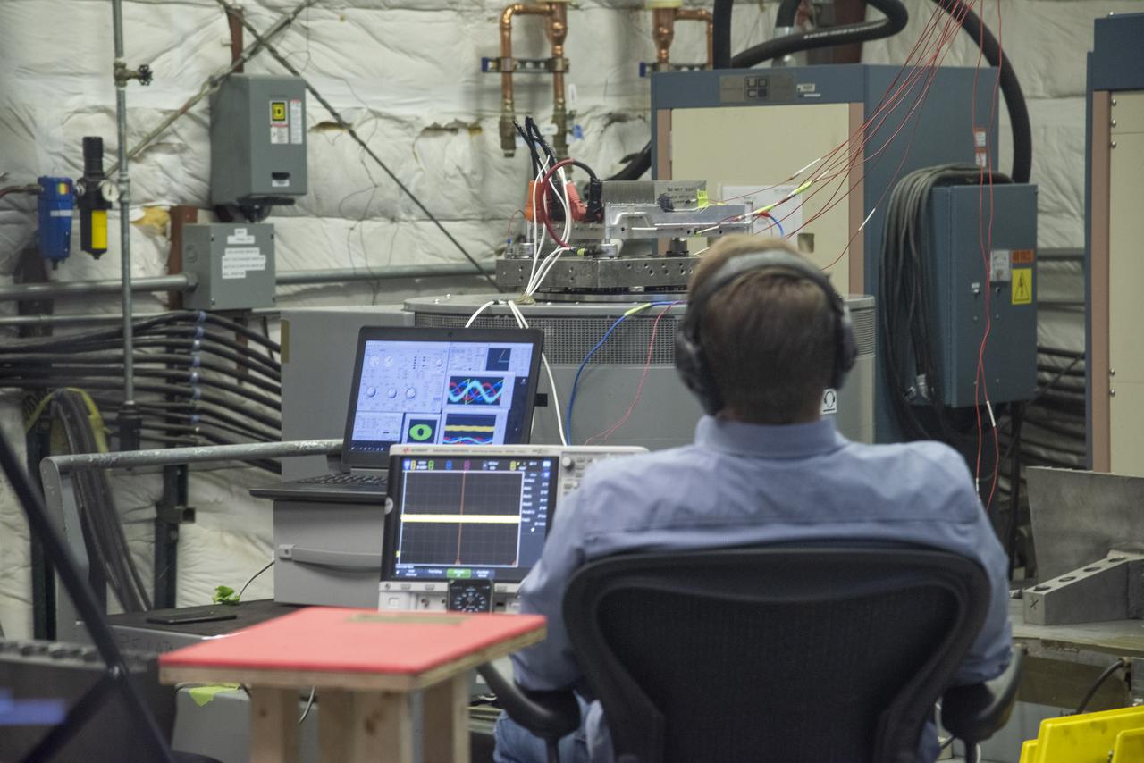
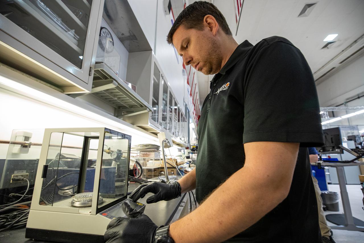
Engineers monitor data during vibration testing of a cruise motor controller for the X-57 Maxwell, NASA's first all-electric X-plane. Attached to a table at NASA Armstrong Flight Research Center's environmental lab, the cruise motor controller is exposed to specific levels of vibration, allowing NASA to examine the structural integrity of the hardware. Engineers, meanwhile, monitored data, including waveforms of electrical current, and recorded readings.

Engineers monitor data during vibration testing of a cruise motor controller for the X-57 Maxwell, NASA's first all-electric X-plane. Attached to a table at NASA Armstrong Flight Research Center's environmental lab, the cruise motor controller is exposed to specific levels of vibration, allowing NASA to examine the structural integrity of the hardware. Engineers, meanwhile, monitored data, including waveforms of electrical current, and recorded readings.
Engineers monitor data during vibration testing of a cruise motor controller for the X-57 Maxwell, NASA’s first all-electric X-plane. Attached to a table at NASA Armstrong Flight Research Center’s environmental lab, the cruise motor controller is exposed to specific levels of vibration, allowing NASA to examine the structural integrity of the hardware. Engineers, meanwhile, monitored data, including waveforms of electrical current, and recorded readings.
Engineers monitor data during vibration testing of a cruise motor controller for the X-57 Maxwell, NASA's first all-electric X-plane. Attached to a table at NASA Armstrong Flight Research Center's environmental lab, the cruise motor controller is exposed to specific levels of vibration, allowing NASA to examine the structural integrity of the hardware. Engineers, meanwhile, monitored data, including waveforms of electrical current, and recorded readings.
Engineers monitor data during vibration testing of a cruise motor controller for the X-57 Maxwell, NASA's first all-electric X-plane. Attached to a table at NASA Armstrong Flight Research Center's environmental lab, the cruise motor controller is exposed to specific levels of vibration, allowing NASA to examine the structural integrity of the hardware. Engineers, meanwhile, monitored data, including waveforms of electrical current, and recorded readings.
Engineers monitor data during vibration testing of a cruise motor controller for the X-57 Maxwell, NASA's first all-electric X-plane. Attached to a table at NASA Armstrong Flight Research Center's environmental lab, the cruise motor controller is exposed to specific levels of vibration, allowing NASA to examine the structural integrity of the hardware. Engineers, meanwhile, monitored data, including waveforms of electrical current, and recorded readings.
Engineers monitor data during vibration testing of a cruise motor controller for the X-57 Maxwell, NASA's first all-electric X-plane. Attached to a table at NASA Armstrong Flight Research Center's environmental lab, the cruise motor controller is exposed to specific levels of vibration, allowing NASA to examine the structural integrity of the hardware. Engineers, meanwhile, monitored data, including waveforms of electrical current, and recorded readings.
Engineers monitor data during vibration testing of a cruise motor controller for the X-57 Maxwell, NASA's first all-electric X-plane. Attached to a table at NASA Armstrong Flight Research Center's environmental lab, the cruise motor controller is exposed to specific levels of vibration, allowing NASA to examine the structural integrity of the hardware. Engineers, meanwhile, monitored data, including waveforms of electrical current, and recorded readings.
Engineers monitor data during vibration testing of a cruise motor controller for the X-57 Maxwell, NASA’s first all-electric X-plane. Attached to a table at NASA Armstrong Flight Research Center’s environmental lab, the cruise motor controller is exposed to specific levels of vibration, allowing NASA to examine the structural integrity of the hardware. Engineers, meanwhile, monitored data, including waveforms of electrical current, and recorded readings.
Engineers monitor data during vibration testing of a cruise motor controller for the X-57 Maxwell, NASA's first all-electric X-plane. Attached to a table at NASA Armstrong Flight Research Center's environmental lab, the cruise motor controller is exposed to specific levels of vibration, allowing NASA to examine the structural integrity of the hardware. Engineers, meanwhile, monitored data, including waveforms of electrical current, and recorded readings.
Engineers monitor data during vibration testing of a cruise motor controller for the X-57 Maxwell, NASA’s first all-electric X-plane. Attached to a table at NASA Armstrong Flight Research Center’s environmental lab, the cruise motor controller is exposed to specific levels of vibration, allowing NASA to examine the structural integrity of the hardware. Engineers, meanwhile, monitored data, including waveforms of electrical current, and recorded readings.
Engineers monitor data during vibration testing of a cruise motor controller for the X-57 Maxwell, NASA’s first all-electric X-plane. Attached to a table at NASA Armstrong Flight Research Center’s environmental lab, the cruise motor controller is exposed to specific levels of vibration, allowing NASA to examine the structural integrity of the hardware. Engineers, meanwhile, monitored data, including waveforms of electrical current, and recorded readings.
Engineers monitor data during vibration testing of a cruise motor controller for the X-57 Maxwell, NASA's first all-electric X-plane. Attached to a table at NASA Armstrong Flight Research Center's environmental lab, the cruise motor controller is exposed to specific levels of vibration, allowing NASA to examine the structural integrity of the hardware. Engineers, meanwhile, monitored data, including waveforms of electrical current, and recorded readings.
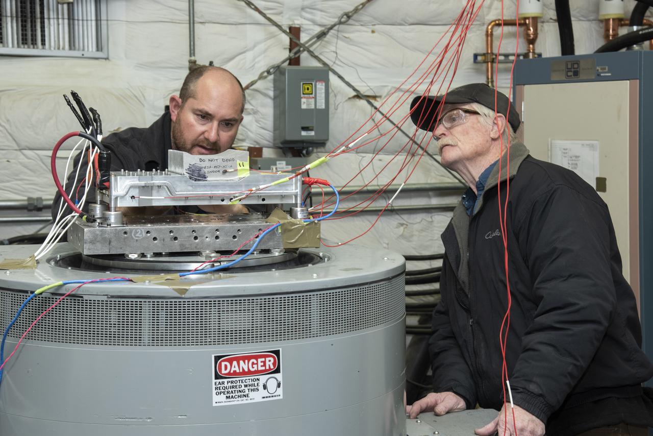
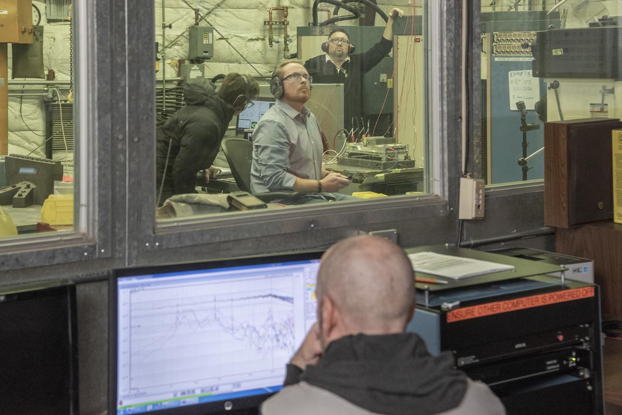
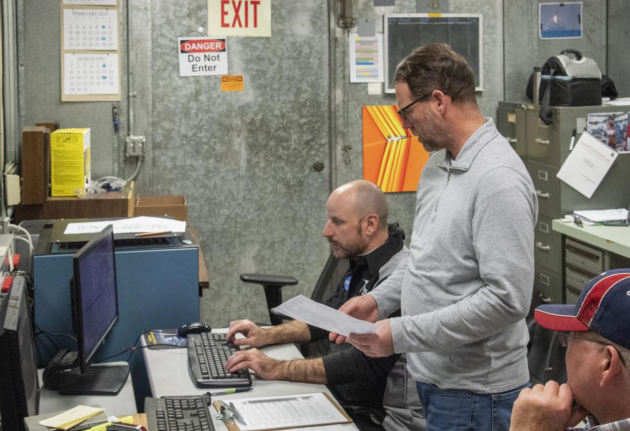
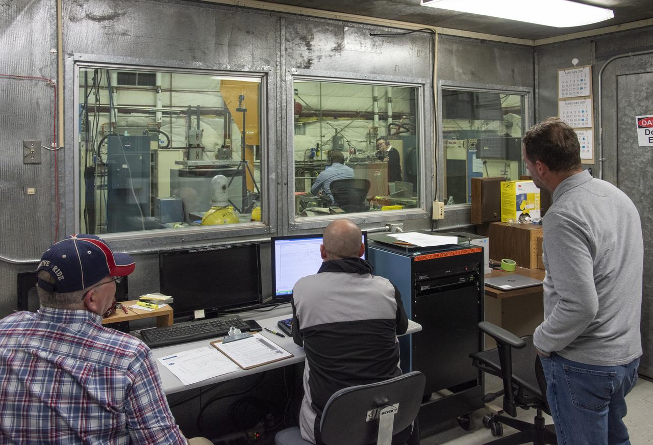
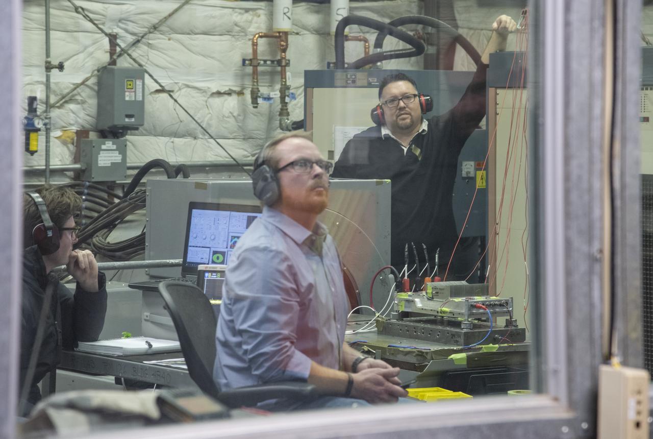
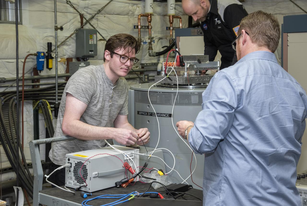
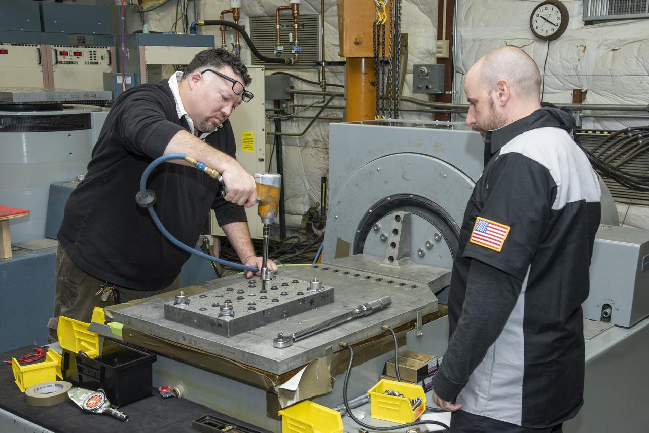
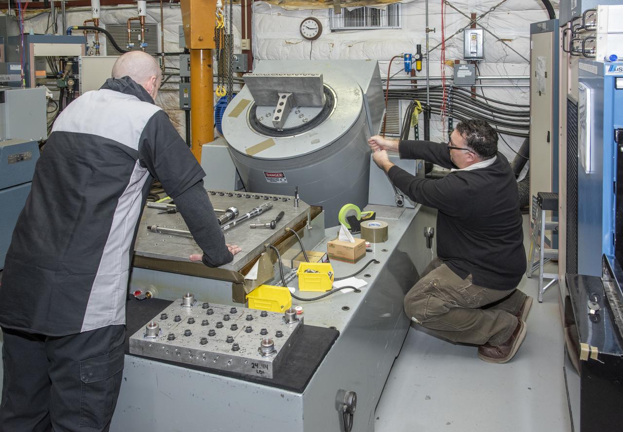
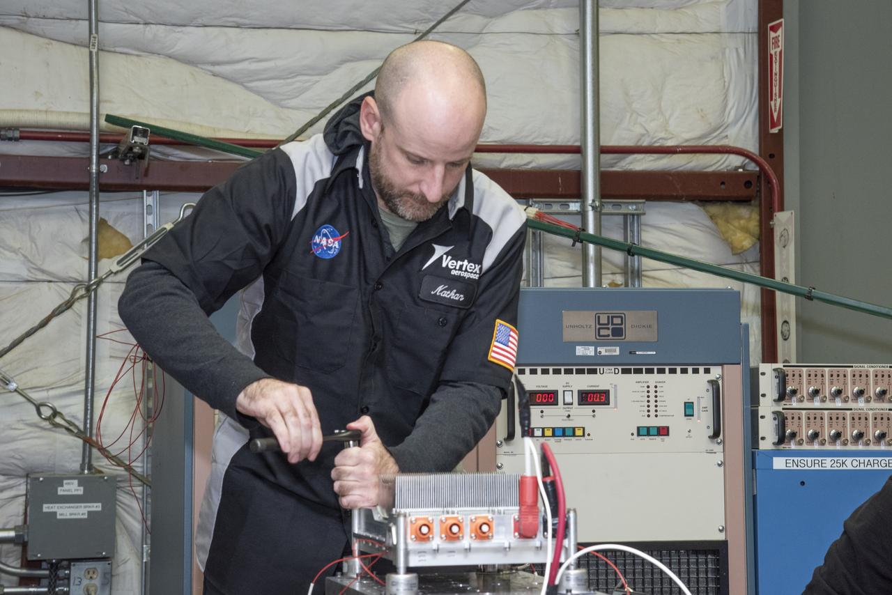
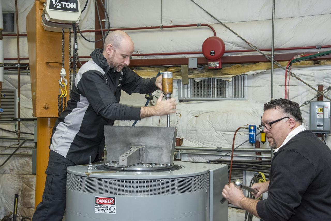
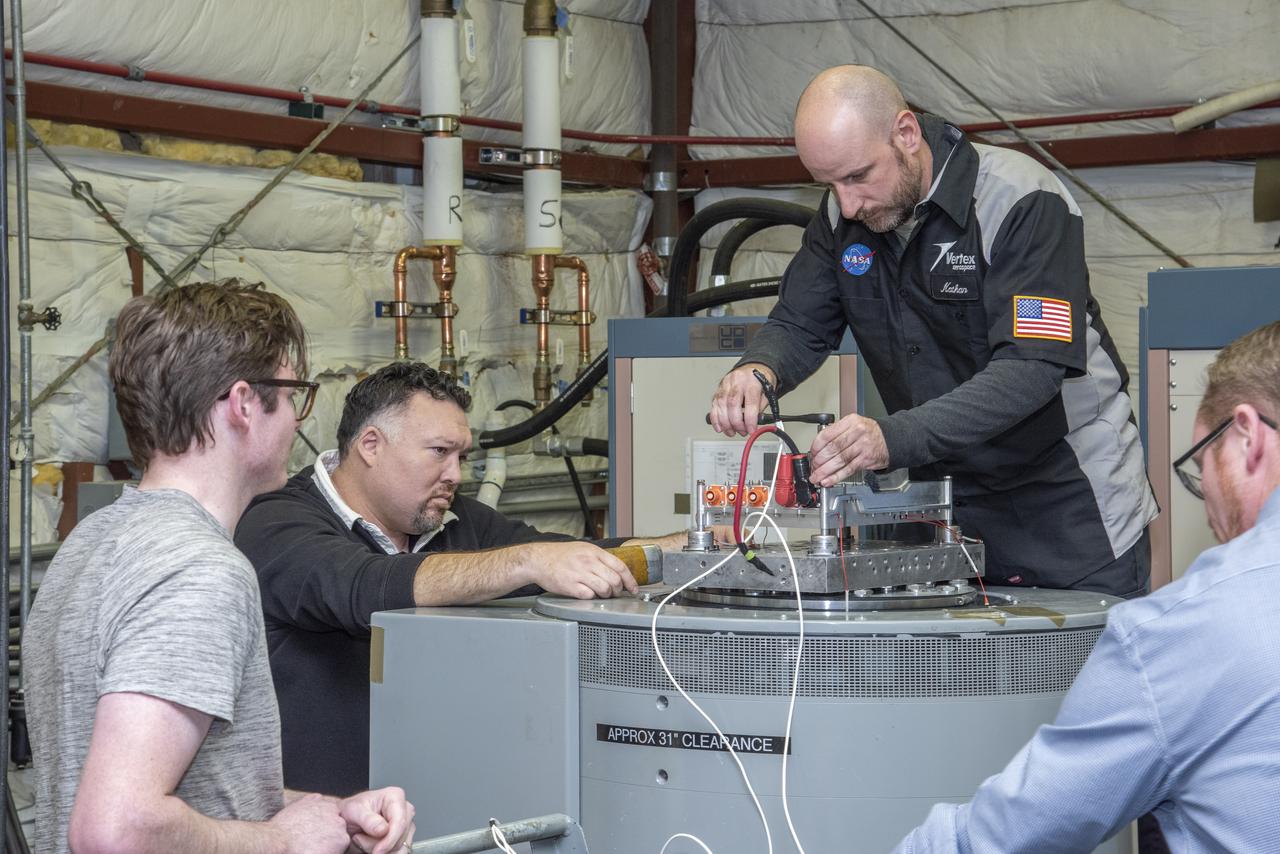
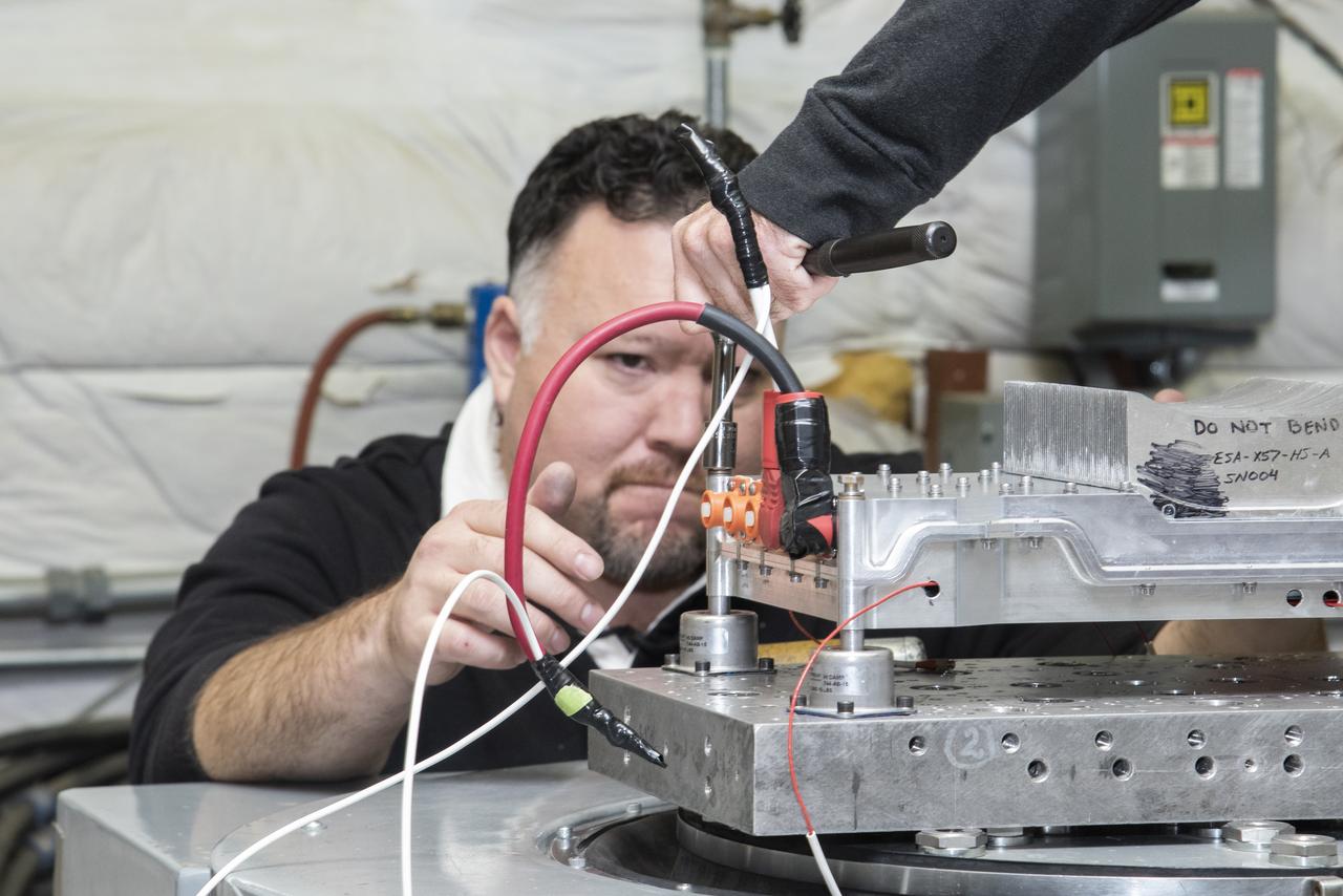
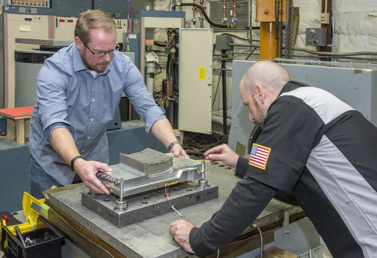
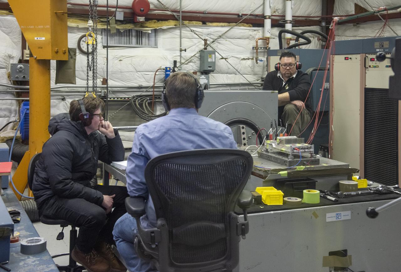
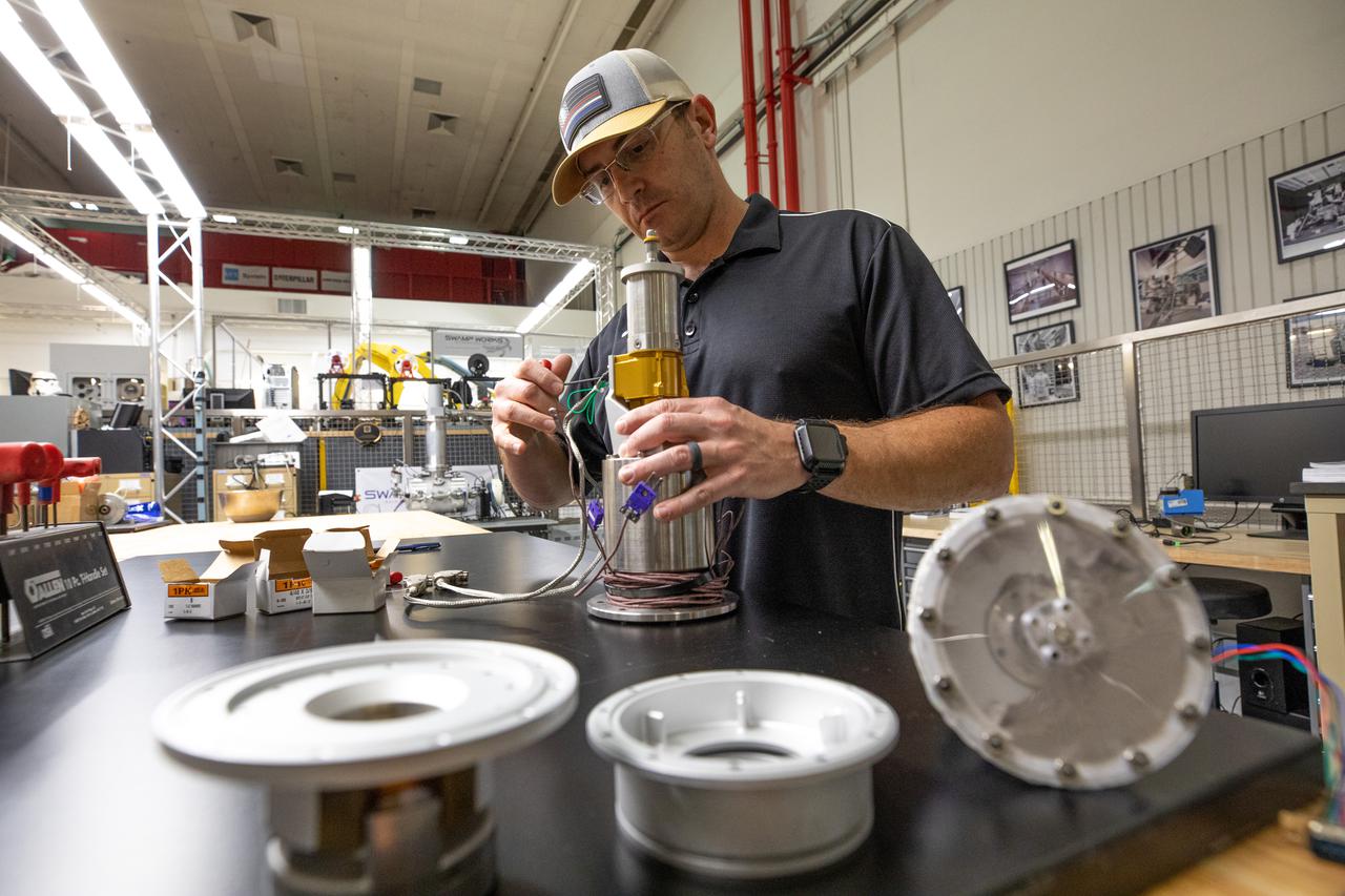
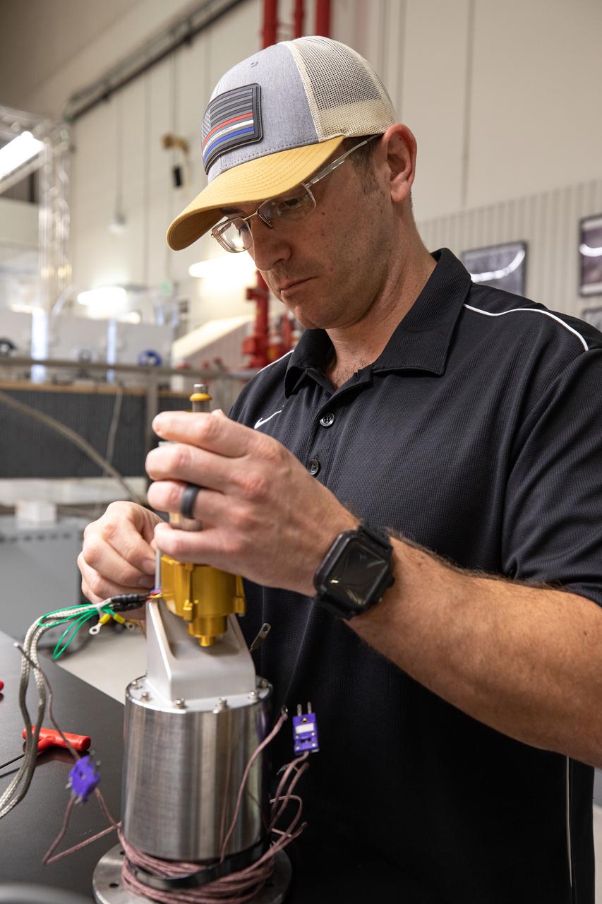
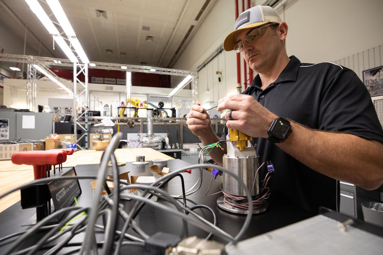
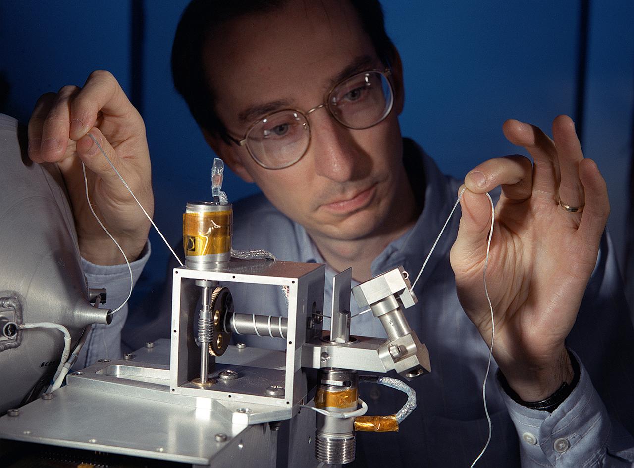
Engineers from NASA's Armstrong Flight Research Center and Empirical Systems Aerospace prepare a cruise motor controller, planned to be used on NASA's all-electric X-57 Maxwell, for vibration testing at Armstrong's environmental lab. Testing the cruise motor controller at various vibration levels, based on baseline flight testing in the project's first phase, helps ensure that the hardware will withstand similar vibration in flight conditions. X-57, NASAs first all-electric experimental aircraft, or X-plane, will fly in its first all-electric configuration in 2020.
Engineers from NASA's Armstrong Flight Research Center and Empirical Systems Aerospace prepare a cruise motor controller, planned to be used on NASA's all-electric X-57 Maxwell, for vibration testing at Armstrong's environmental lab. Testing the cruise motor controller at various vibration levels, based on baseline flight testing in the project's first phase, helps ensure that the hardware will withstand similar vibration in flight conditions. X-57, NASA's first all-electric experimental aircraft, or X-plane, will fly in its first all-electric configuration in 2020.
Engineers from NASA's Armstrong Flight Research Center and Empirical Systems Aerospace prepare a cruise motor controller, planned to be used on NASA's all-electric X-57 Maxwell, for vibration testing at Armstrong's environmental lab. Testing the cruise motor controller at various vibration levels, based on baseline flight testing in the project's first phase, helps ensure that the hardware will withstand similar vibration in flight conditions. X-57, NASA's first all-electric experimental aircraft, or X-plane, will fly in its first all-electric configuration in 2020.
Engineers from NASA's Armstrong Flight Research Center and Empirical Systems Aerospace prepare a cruise motor controller, planned to be used on NASA's all-electric X-57 Maxwell, for vibration testing at Armstrong's environmental lab. Testing the cruise motor controller at various vibration levels, based on baseline flight testing in the project's first phase, helps ensure that the hardware will withstand similar vibration in flight conditions. X-57, NASA's first all-electric experimental aircraft, or X-plane, will fly in its first all-electric configuration in 2020.
Engineers from NASA's Armstrong Flight Research Center and Empirical Systems Aerospace prepare a cruise motor controller, planned to be used on NASA's all-electric X-57 Maxwell, for vibration testing at Armstrong's environmental lab. Testing the cruise motor controller at various vibration levels, based on baseline flight testing in the project's first phase, helps ensure that the hardware will withstand similar vibration in flight conditions. X-57, NASA's first all-electric experimental aircraft, or X-plane, will fly in its first all-electric configuration in 2020.
Engineers from NASA's Armstrong Flight Research Center and Empirical Systems Aerospace prepare a cruise motor controller, planned to be used on NASA's all-electric X-57 Maxwell, for vibration testing at Armstrong's environmental lab. Testing the cruise motor controller at various vibration levels, based on baseline flight testing in the project's first phase, helps ensure that the hardware will withstand similar vibration in flight conditions. X-57, NASA's first all-electric experimental aircraft, or X-plane, will fly in its first all-electric configuration in 2020.
Engineers from NASA's Armstrong Flight Research Center and Empirical Systems Aerospace prepare a cruise motor controller, planned to be used on NASA's all-electric X-57 Maxwell, for vibration testing at Armstrong's environmental lab. Testing the cruise motor controller at various vibration levels, based on baseline flight testing in the project's first phase, helps ensure that the hardware will withstand similar vibration in flight conditions. X-57, NASA's first all-electric experimental aircraft, or X-plane, will fly in its first all-electric configuration in 2020.
Engineers from NASA's Armstrong Flight Research Center and Empirical Systems Aerospace prepare a cruise motor controller, planned to be used on NASA's all-electric X-57 Maxwell, for vibration testing at Armstrong's environmental lab. Testing the cruise motor controller at various vibration levels, based on baseline flight testing in the project's first phase, helps ensure that the hardware will withstand similar vibration in flight conditions. X-57, NASA's first all-electric experimental aircraft, or X-plane, will fly in its first all-electric configuration in 2020.
Engineers from NASA's Armstrong Flight Research Center and Empirical Systems Aerospace prepare a cruise motor controller, planned to be used on NASA's all-electric X-57 Maxwell, for vibration testing at Armstrong's environmental lab. Testing the cruise motor controller at various vibration levels, based on baseline flight testing in the project's first phase, helps ensure that the hardware will withstand similar vibration in flight conditions. X-57, NASA's first all-electric experimental aircraft, or X-plane, will fly in its first all-electric configuration in 2020.
Engineers from NASA's Armstrong Flight Research Center and Empirical Systems Aerospace prepare a cruise motor controller, planned to be used on NASA's all-electric X-57 Maxwell, for vibration testing at Armstrong's environmental lab. Testing the cruise motor controller at various vibration levels, based on baseline flight testing in the project's first phase, helps ensure that the hardware will withstand similar vibration in flight conditions. X-57, NASA's first all-electric experimental aircraft, or X-plane, will fly in its first all-electric configuration in 2020.
Engineers from NASA's Armstrong Flight Research Center and Empirical Systems Aerospace prepare a cruise motor controller, planned to be used on NASA's all-electric X-57 Maxwell, for vibration testing at Armstrong's environmental lab. Testing the cruise motor controller at various vibration levels, based on baseline flight testing in the project's first phase, helps ensure that the hardware will withstand similar vibration in flight conditions. X-57, NASA's first all-electric experimental aircraft, or X-plane, will fly in its first all-electric configuration in 2020.
Engineers from NASA's Armstrong Flight Research Center and Empirical Systems Aerospace prepare a cruise motor controller, planned to be used on NASA's all-electric X-57 Maxwell, for vibration testing at Armstrong's environmental lab. Testing the cruise motor controller at various vibration levels, based on baseline flight testing in the project's first phase, helps ensure that the hardware will withstand similar vibration in flight conditions. X-57, NASA's first all-electric experimental aircraft, or X-plane, will fly in its first all-electric configuration in 2020.
Engineers from NASA's Armstrong Flight Research Center and Empirical Systems Aerospace prepare a cruise motor controller, planned to be used on NASA's all-electric X-57 Maxwell, for vibration testing at Armstrong's environmental lab. Testing the cruise motor controller at various vibration levels, based on baseline flight testing in the project's first phase, helps ensure that the hardware will withstand similar vibration in flight conditions. X-57, NASA's first all-electric experimental aircraft, or X-plane, will fly in its first all-electric configuration in 2020.
Engineers from NASA’s Armstrong Flight Research Center and Empirical Systems Aerospace prepare a cruise motor controller, planned to be used on NASA’s all-electric X-57 Maxwell, for vibration testing at Armstrong’s environmental lab. Testing the cruise motor controller at various vibration levels, based on baseline flight testing in the project’s first phase, helps ensure that the hardware will withstand similar vibration in flight conditions. X-57, NASA’s first all-electric experimental aircraft, or X-plane, will fly in its first all-electric configuration in 2020.
Engineers from NASA's Armstrong Flight Research Center and Empirical Systems Aerospace prepare a cruise motor controller, planned to be used on NASA's all-electric X-57 Maxwell, for vibration testing at Armstrong's environmental lab. Testing the cruise motor controller at various vibration levels, based on baseline flight testing in the project's first phase, helps ensure that the hardware will withstand similar vibration in flight conditions. X-57, NASA's first all-electric experimental aircraft, or X-plane, will fly in its first all-electric configuration in 2020.
Engineers from NASA's Armstrong Flight Research Center and Empirical Systems Aerospace prepare a cruise motor controller, planned to be used on NASA's all-electric X-57 Maxwell, for vibration testing at Armstrong's environmental lab. Testing the cruise motor controller at various vibration levels, based on baseline flight testing in the project's first phase, helps ensure that the hardware will withstand similar vibration in flight conditions. X-57, NASA's first all-electric experimental aircraft, or X-plane, will fly in its first all-electric configuration in 2020.
Engineers from NASA’s Armstrong Flight Research Center and Empirical Systems Aerospace prepare a cruise motor controller, planned to be used on NASA’s all-electric X-57 Maxwell, for vibration testing at Armstrong’s environmental lab. Testing the cruise motor controller at various vibration levels, based on baseline flight testing in the project’s first phase, helps ensure that the hardware will withstand similar vibration in flight conditions. X-57, NASA’s first all-electric experimental aircraft, or X-plane, will fly in its first all-electric configuration in 2020.
Engineers from NASA's Armstrong Flight Research Center and Empirical Systems Aerospace prepare a cruise motor controller, planned to be used on NASA's all-electric X-57 Maxwell, for vibration testing at Armstrong's environmental lab. Testing the cruise motor controller at various vibration levels, based on baseline flight testing in the project's first phase, helps ensure that the hardware will withstand similar vibration in flight conditions. X-57, NASA's first all-electric experimental aircraft, or X-plane, will fly in its first all-electric configuration in 2020.
Engineers from NASA's Armstrong Flight Research Center and Empirical Systems Aerospace prepare a cruise motor controller, planned to be used on NASA's all-electric X-57 Maxwell, for vibration testing at Armstrong's environmental lab. Testing the cruise motor controller at various vibration levels, based on baseline flight testing in the project's first phase, helps ensure that the hardware will withstand similar vibration in flight conditions. X-57, NASA's first all-electric experimental aircraft, or X-plane, will fly in its first all-electric configuration in 2020.
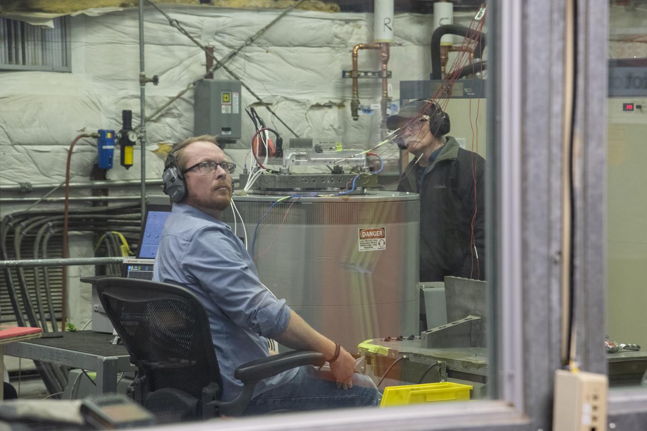
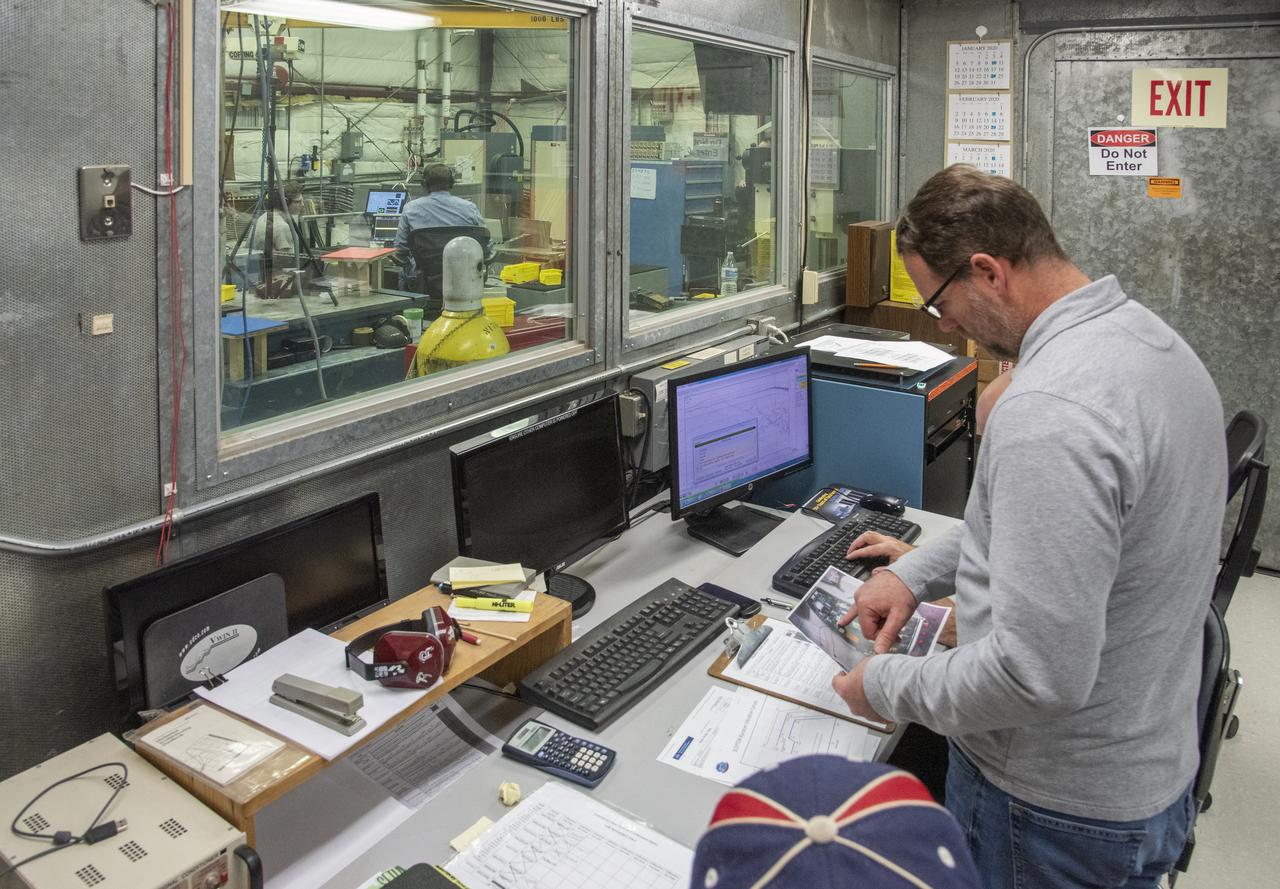
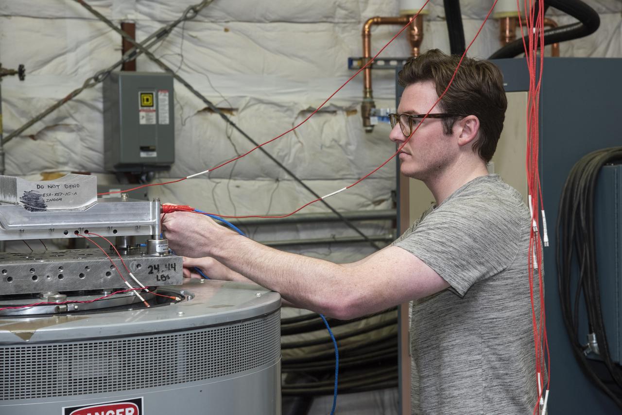
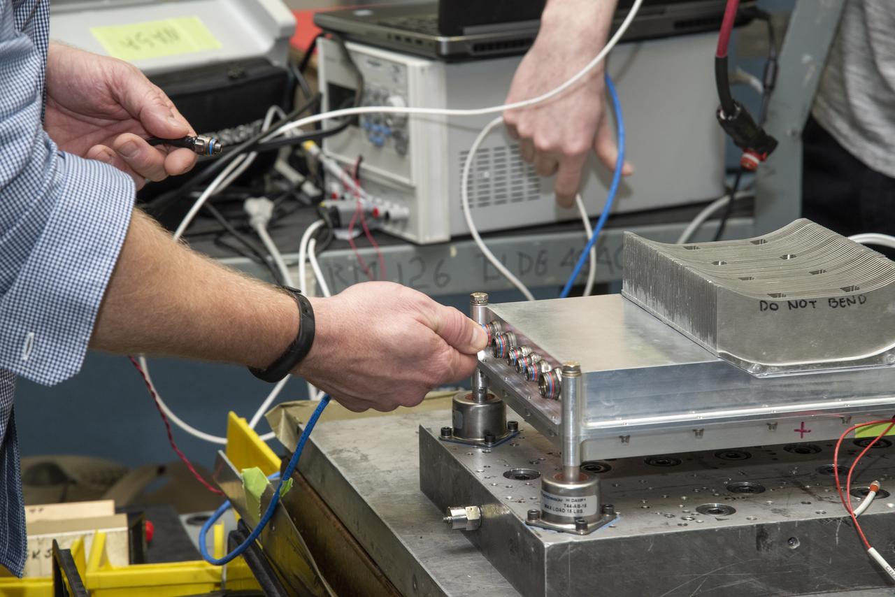
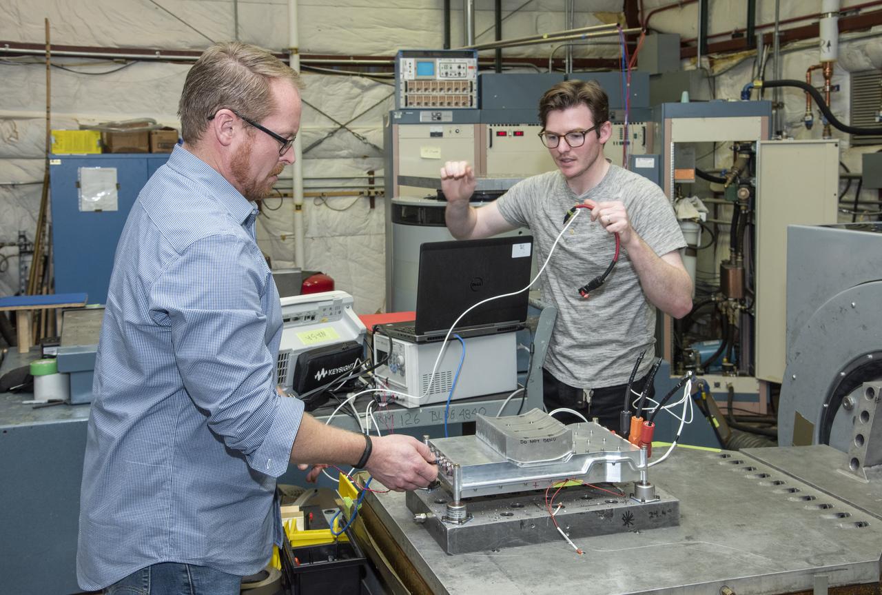
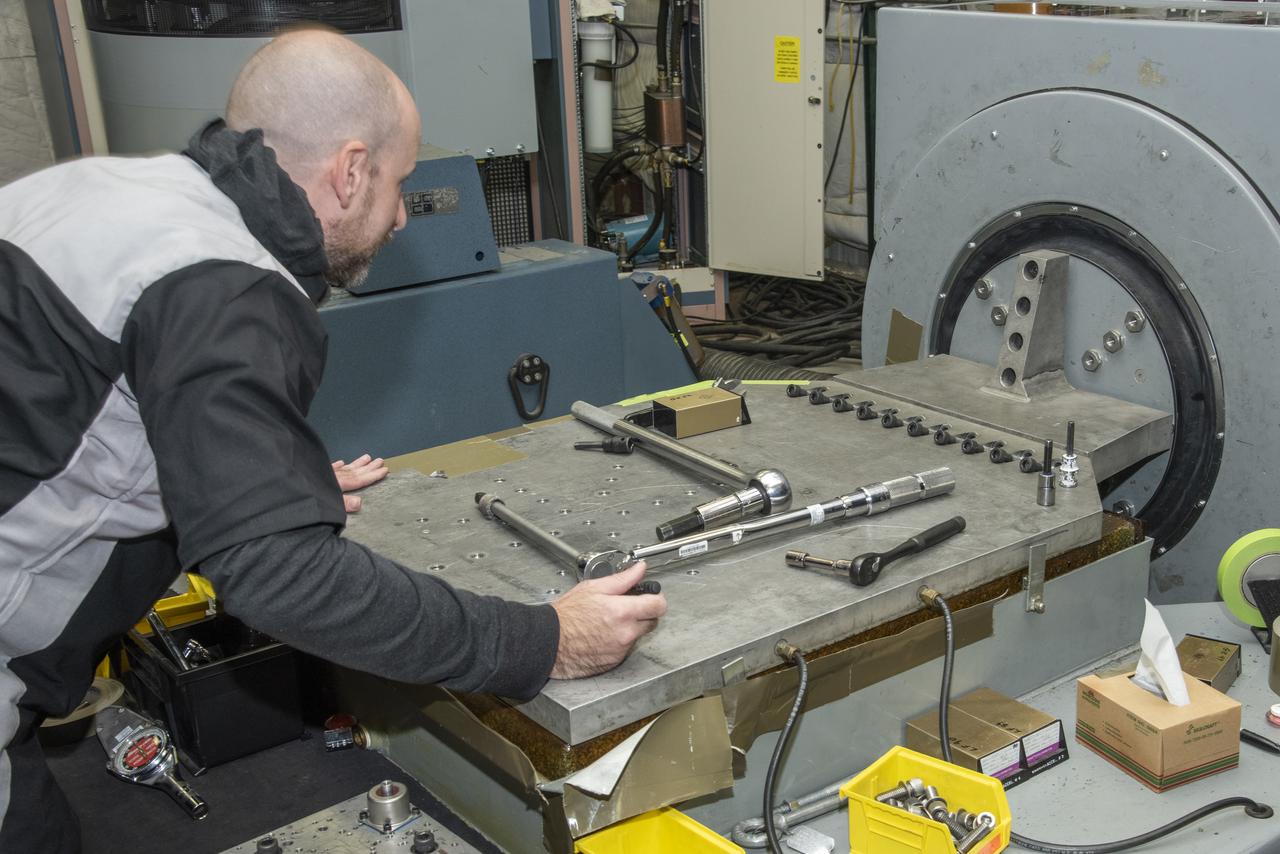
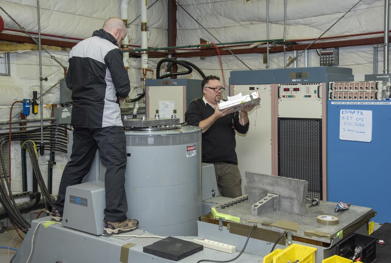
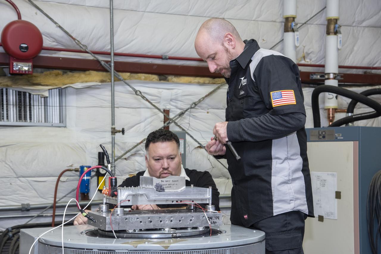
A cruise motor controller for the X-57 Maxwell, NASA’s first all-electric X-plane, undergoes vibration testing at NASA Armstrong Flight Research Center’s environmental lab. The cruise motor controller is exposed to two levels of vibration on three different axes, helping NASA to examine the integrity of the controller for flight conditions. The cruise motor controller will be a critical component for providing power to X-57’s motors when the aircraft takes to the skies in 2020.
A cruise motor controller for the X-57 Maxwell, NASA's first all-electric X-plane, undergoes vibration testing at NASA Armstrong Flight Research Center's environmental lab. The cruise motor controller is exposed to two levels of vibration on three different axes, helping NASA to examine the integrity of the controller for flight conditions. The cruise motor controller will be a critical component for providing power to X-57's motors when the aircraft takes to the skies in 2020.
A cruise motor controller for the X-57 Maxwell, NASA's first all-electric X-plane, undergoes vibration testing at NASA Armstrong Flight Research Center's environmental lab. The cruise motor controller is exposed to two levels of vibration on three different axes, helping NASA to examine the integrity of the controller for flight conditions. The cruise motor controller will be a critical component for providing power to X-57's motors when the aircraft takes to the skies in 2020.
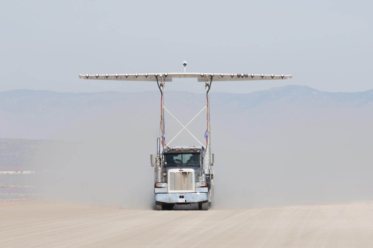
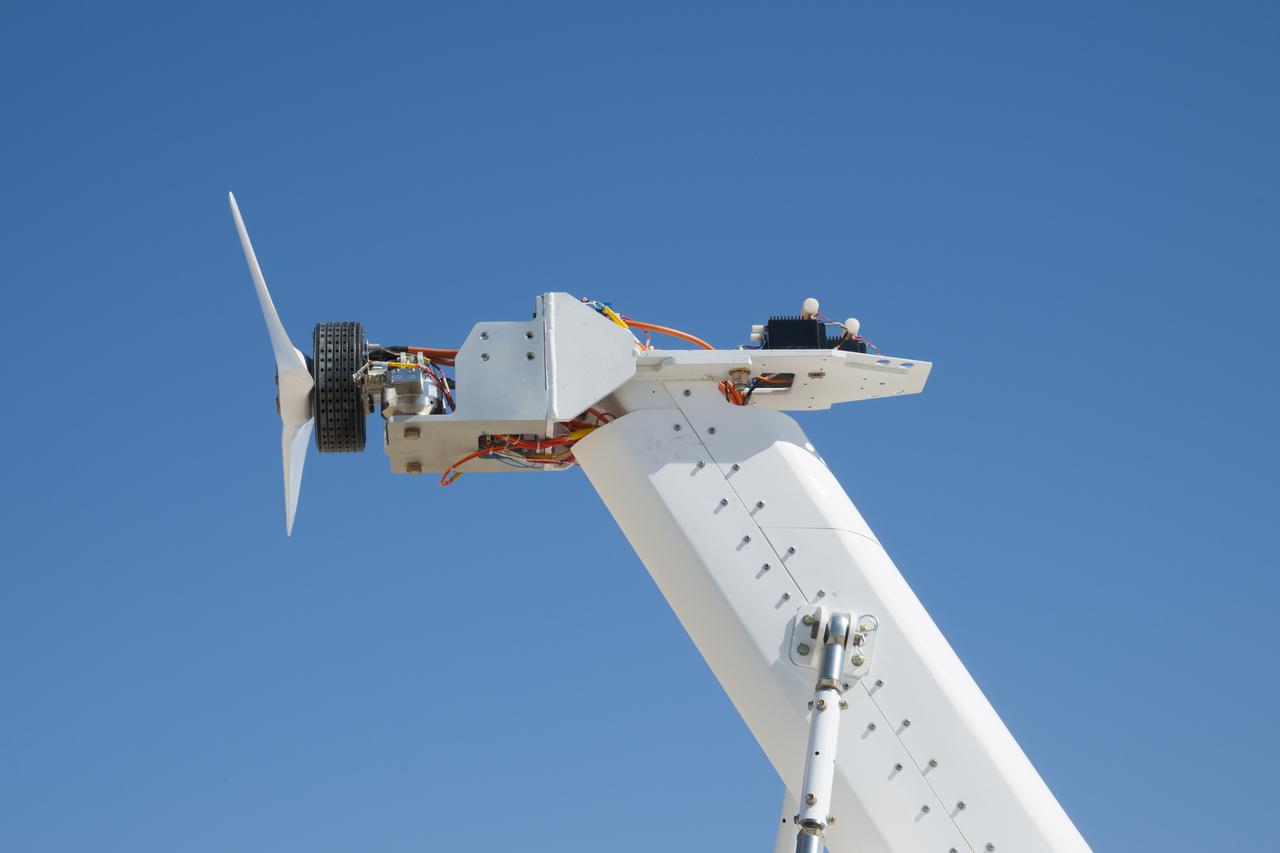
Engineers gather aerodynamic data on the integrated experimental testbed without the electric motor propellers.
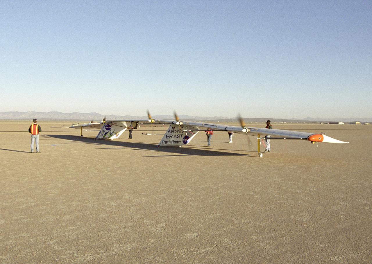
AeroVironment ground crew check out the operation of the Pathfinder-Plus solar aircraft's electric motors during combined systems tests on Rogers Dry Lake.
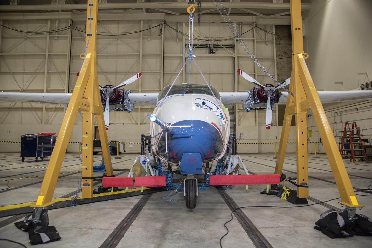
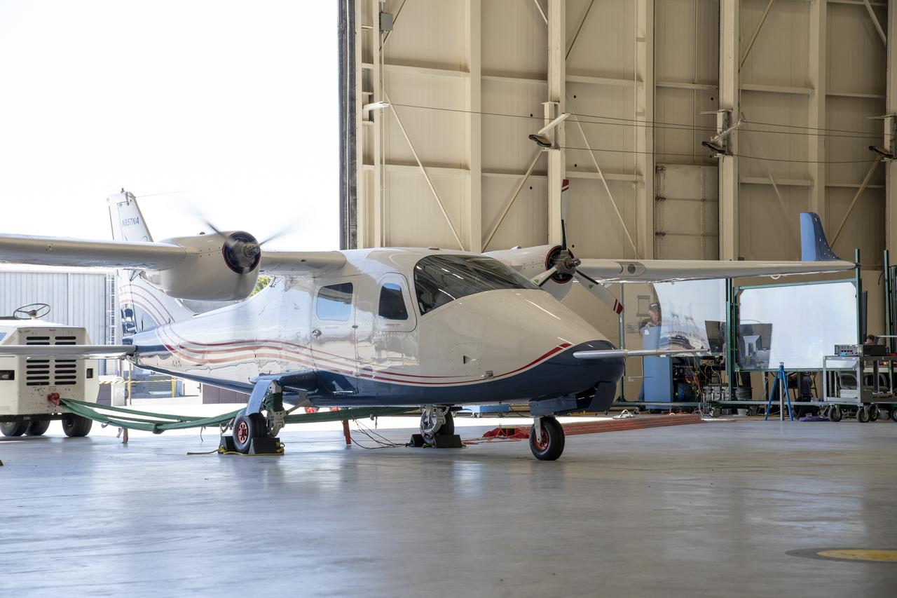
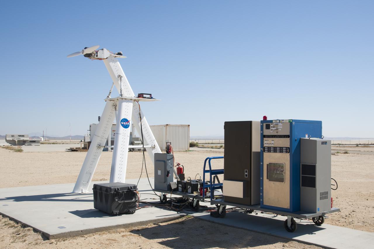
NASA’s all-electric X-57 Maxwell prepares for ground vibration testing, or GVT, at NASA’s Armstrong Flight Research Center in California. Done in parallel with cruise motor controller testing, the GVT tested the vehicle at various vibration levels, helping engineers to examine and validate the integrity of the vehicle for flight conditions. A goal of X-57 is to help the Federal Aviation Administration set certification standards for emerging electric aircraft markets.
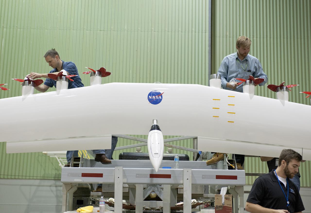
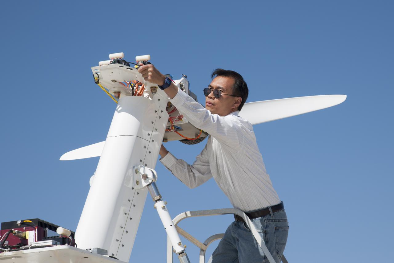
Engineers work on a wing with electric motors that is part of an integrated experimental testbed. From left are Sean Clarke, left, Kurt Papathakis at upper right and Anthony Cash in the foreground.

Motor and propeller blades in 40x80ft wind tunnel. Six 40-foot-diameter fans, each powered by a 6000-horsepower electric motor maintained airflow at 230 mph or less (these are still tornado velocities).
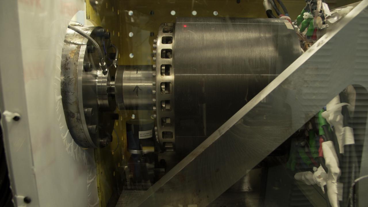
UIUC’s megawatt machine (right) was connected to a dynamometer (left) to test its effectiveness as an electric generator in a safety enclosure at a Collins Aerospace test facility in Rockford, Illinois. This unusual design has its rotating parts on the outside, so that both the cylinder on the right and the cylinder with arrows spin during operation.
NASA's all-electric X-57 Maxwell aircraft tests the motors with the battery packs installed on the aircraft at NASA's Armstrong Flight Research Center in California. A goal of the X-57 project is to help the Federal Aviation Administration set certification standards for emerging electric aircraft markets.
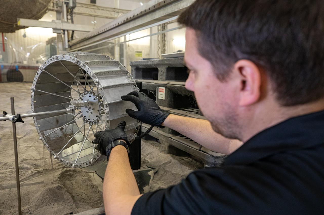
Researchers at NASA's Kennedy Space Center are testing the various types of seals for electric motors that drive the Volatiels Investigating Polar Exploration Rover, or VIPER, wheels at Swamp Works.
Researchers at NASA's Kennedy Space Center are testing the various types of seals for electric motors that drive the Volatiels Investigating Polar Exploration Rover, or VIPER, wheels at Swamp Works.
Researchers at NASA's Kennedy Space Center are testing the various types of seals for electric motors that drive the Volatiels Investigating Polar Exploration Rover, or VIPER, wheels at Swamp Works.
Researchers at NASA's Kennedy Space Center are testing the various types of seals for electric motors that drive the Volatiels Investigating Polar Exploration Rover, or VIPER, wheels at Swamp Works.
Researchers at NASA's Kennedy Space Center are testing the various types of seals for electric motors that drive the Volatiels Investigating Polar Exploration Rover, or VIPER, wheels at Swamp Works.

Construction workers install the drive motor for the Altitude Wind Tunnel (AWT) in the Exhauster Building at the National Advisory Committee for Aeronautics (NACA) Aircraft Engine Research Laboratory. The AWT was capable of operating full-scale engines in air density, speed, and temperature similar to that found at high altitudes. The tunnel could produce wind speeds up to 500 miles per hour through a 20-foot-diameter test section at the standard operating altitude of 30,000 feet. The airflow was created by a large wooden fan near the tunnel’s southeast corner. This photograph shows the installation of the 18,000-horsepower drive motor inside the adjoining Exhauster Building in July 1943. The General Electric motor, whose support frame is seen in this photograph, connected to a drive shaft that extended from the building, through the tunnel shell, and into a 12-bladed, 31-foot-diameter spruce wood fan. Flexible couplings on the shaft allowed for the movement of the shell. The corner of the Exhauster Building was built around the motor after its installation. The General Electric induction motor could produce 10 to 410 revolutions per minute and create wind speeds up to 500 miles per hour, or Mach 0.63, at 30,000 feet. The AWT became operational in January 1944 and tested piston, turbojet and ramjet engines for nearly 20 years.

ISS016-E-026454 (30 Jan. 2008) --- Astronaut Daniel Tani, Expedition 16 flight engineer, participates in a session of extravehicular activity (EVA) as maintenance and construction continue on the International Space Station. During the 7-hour, 10-minute spacewalk, Tani and astronaut Peggy Whitson (out of frame), commander, replaced a motor, known as the Bearing Motor Roll Ring Module (BMRRM), at the base of one of the station's solar wings. The BMRRM is part of the Beta Gimbal Assembly, which experienced electrical failures Dec. 8.
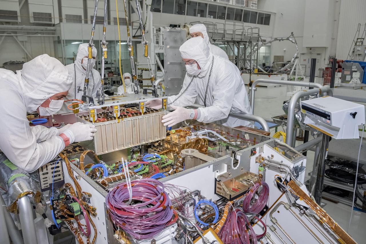
Engineers and technicians at NASA's Jet Propulsion Laboratory in Pasadena, California, integrate the rover motor controller assembly (RMCA) into the Mars 2020 rover's body. The RMCA is the electrical heart of the rover's mobility and motion systems, commanding and regulating the movement of the motors in the rover's wheels, robotic arms, mast, drill and sample-handling functions. The image was taken on April 29, 2019, in the Spacecraft Assembly Facility's High Bay 1 clean room at JPL. https://photojournal.jpl.nasa.gov/catalog/PIA23194
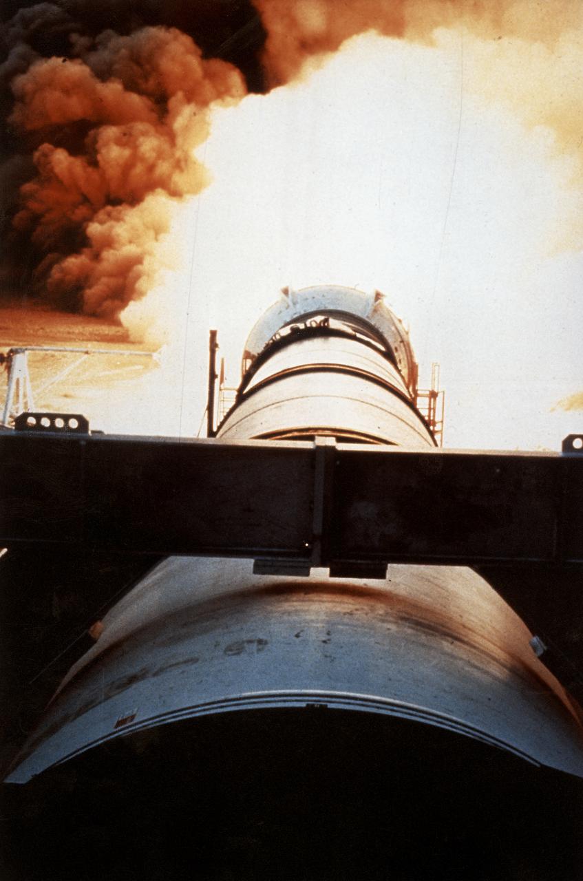
One of the key tests in the effort to return the Space Shuttle to flight following the Challenger accident was testing the development Motor-8 (DM-8). The 126-foot long, 1.2-million-pound motor, designated DM-8, underwent a full-duration horizontal test firing for two minutes at the Thiokol test facility in Utah. It was fitted with more than 500 instruments to measure such things as acceleration, pressure, deflection thrust, strain, temperature, and electrical properties.
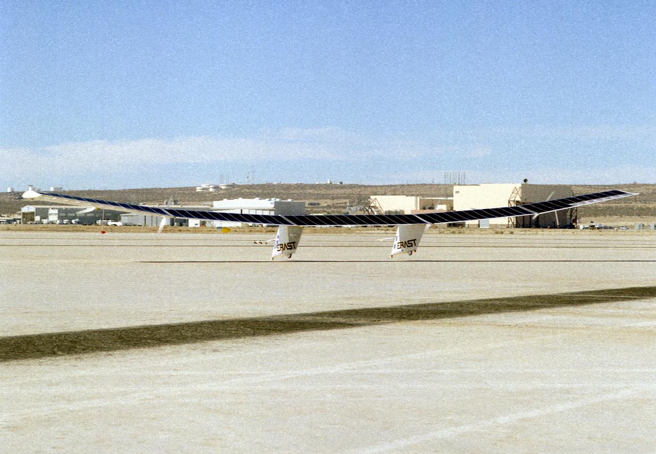
The Pathfinder research aircraft's solar cell arrays are prominently displayed as it touches down on the bed of Rogers Dry Lake at the Dryden Flight Research Center, Edwards, California, following a test flight. The solar arrays covered more than 75 percent of Pathfinder's upper wing surface, and provided electricity to power its six electric motors, flight controls, communications links and a host of scientific sensors.

Lockheed XFV-1 model. Project engineer Mark Kelly (not shown). Remote controlled model flown in the settling chamber of the 40x80 wind tunnel. Electric motors in the model, controlled the counter-rotating propellers to test vertical takeoff. Test no. 71

Dr Condoleezza Rice, United States Secretary of State visits Ames. Takes a demonstration ride in the Tesla Motors Electric Car. Australian Foreign Minister Alexander Downer traveling with Dr Rice addresses the assembled media and Ames staffers
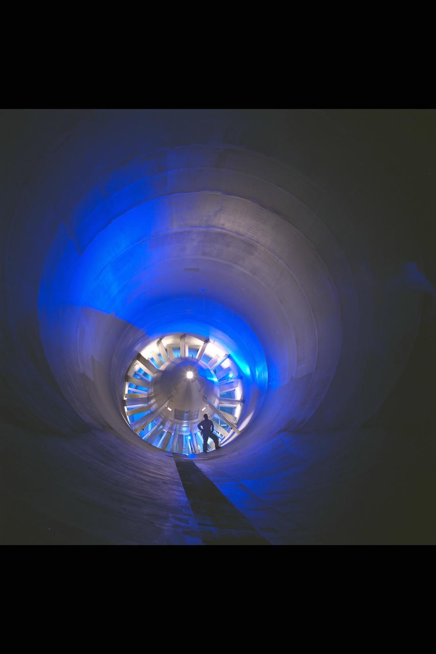
New renovated NASA Ames Research Center 12 foot Pressure Wind Tunnel, seen here is the single stage, 20 blade axial-flow fan powered by a 15,000 horsepower variable speed, synchronous electric motor that provides airflow in the closed-return, variable-density tunnel.
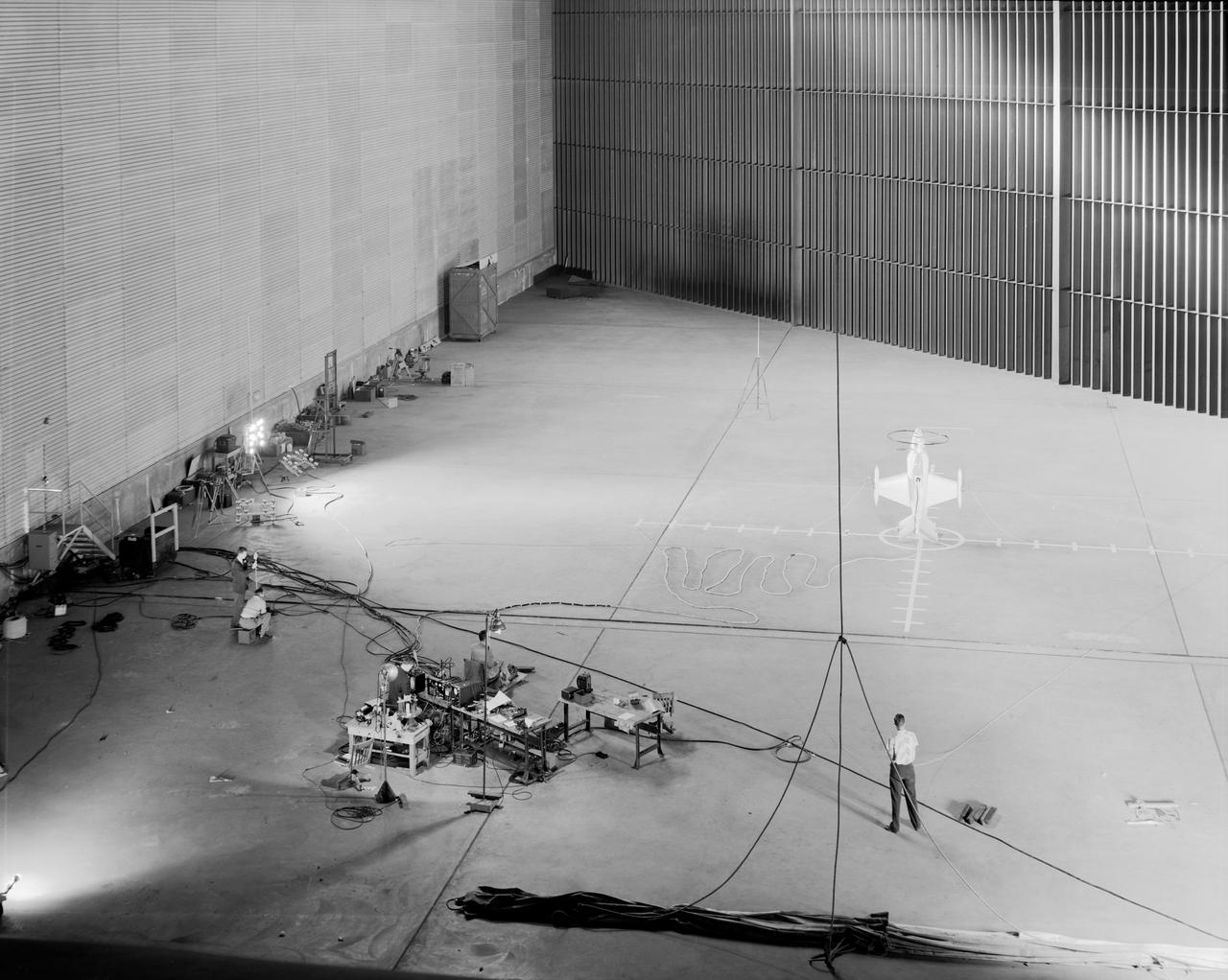
Wide shot of 40x 80 wind tunnel settling chamber with Lockheed XFV-1 model. Project engineer Mark Kelly (not shown). Remote controlled model flown in the settling chamber of the 40x80 wind tunnel. Electric motors in the model, controlled the counter-rotating propellers to test vertical takeoff. Test no. 71

Concrete frame enclosing the fan drive bents of the 40x80 foot wind tunnel at ames. Once installed, six 40-foot-diameter fans, each powered by a 6000-horsepower electric motor maintained airflow at 230 mph or less (these are still tornado velocities).
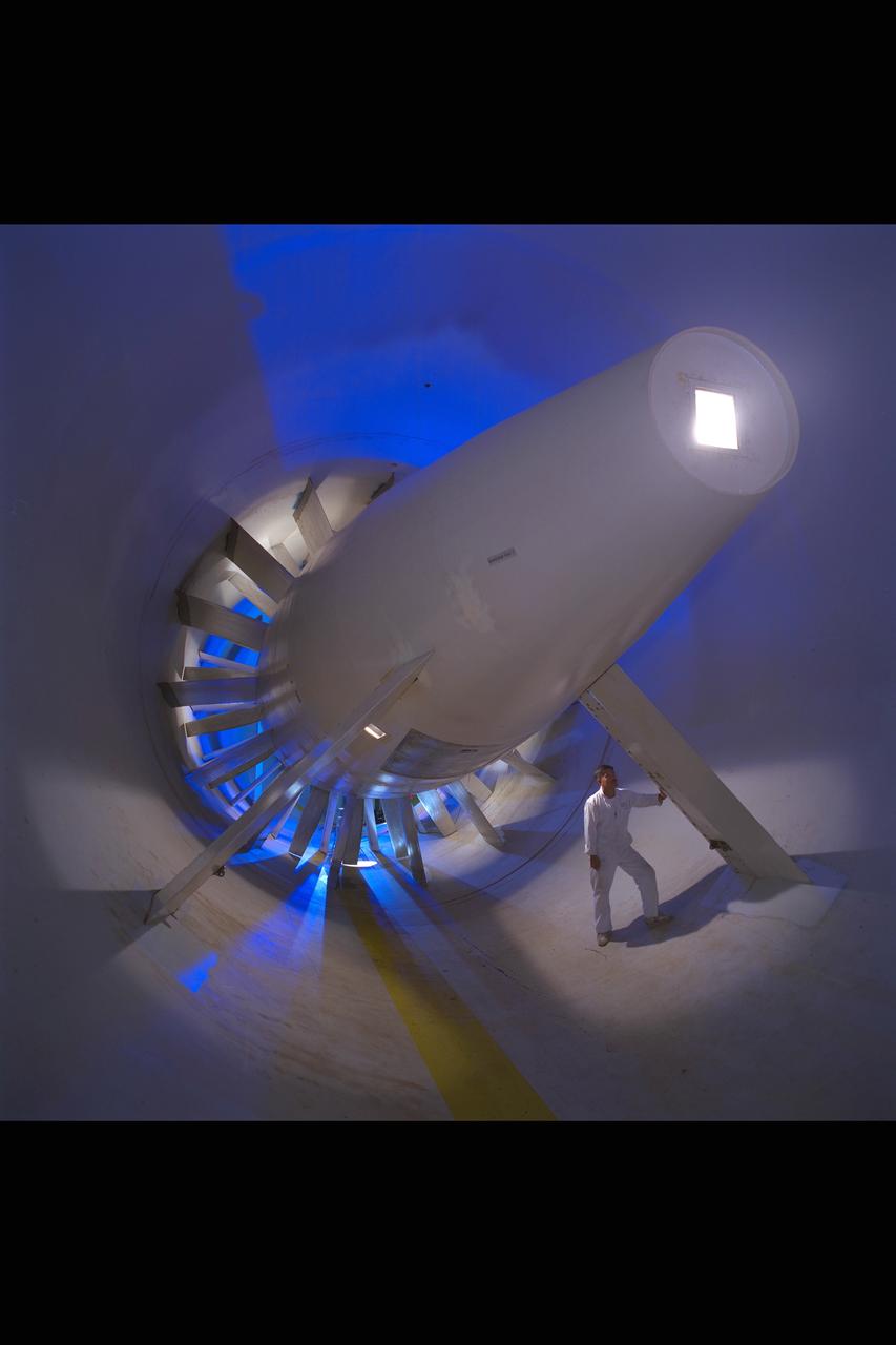
New renovated NASA Ames Research Center 12 foot Pressure Wind Tunnel, seen here is the single stage, 20 blade axial-flow fan powered by a 15,000 horsepower variable speed, synchronous electric motor that provides airflow in the closed-return, variable-density tunnel.
The electric propulsion system to be tested is secured at the top of the Airvolt test stand and instrumented to collect data.
The equipment required for an electric propulsion test is ready for research.
Yohan Lin, Airvolt integration lead, prepares the electric propulsion test stand.
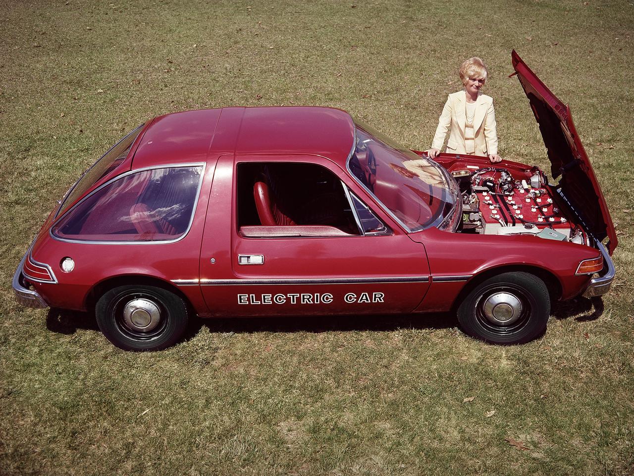
The National Aeronautics and Space Administration (NASA) Lewis Research Center tested 16 commercially-manufactured electric vehicles, including this modified Pacer, during the mid-1970s. The Electric Vehicle Project was just one of several energy-related programs that Lewis and the Energy Research and Development Administration (ERDA) undertook in the mid-1970s. NASA and ERDA embarked on this program in 1976 to determine the state of the current electric vehicle technology. As part of the project, Lewis tested a fleet composed of every commercially available electric car. The Cleveland-area Electric Vehicle Associates modified an American Motors Pacer vehicle to create this Change-of-Pace Coupe. It was powered by twenty 6-volt batteries whose voltage could be varied by a foot control. The tests analyzed the vehicle’s range, acceleration, coast-down, braking, and energy consumption. Some of the vehicles had analog data recording systems to measure the battery during operation and sensors to determine speed and distance. Lewis researchers found that the vehicle performance varied significantly from model to model. In general, the range, acceleration, and speed were lower than conventional vehicles. They also found that traditional gasoline-powered vehicles were as efficient as the electric vehicles. The researchers concluded, however, that advances in battery technology and electric drive systems would significantly improve the performance and efficiency.

ISS016-E-025998 (30 Jan. 2008) --- Astronaut Peggy Whitson, Expedition 16 commander, participates in a session of extravehicular activity (EVA) as maintenance and construction continue on the International Space Station. During the 7-hour, 10-minute spacewalk, Whitson and astronaut Daniel Tani (out of frame), flight engineer, replaced a motor, known as the Bearing Motor Roll Ring Module (BMRRM), at the base of one of the station's solar wings. The BMRRM is part of the Beta Gimbal Assembly, which experienced electrical failures Dec. 8. A blue and white Earth and the blackness of space provide the backdrop for the scene.

ISS016-E-025993 (30 Jan. 2008) --- Astronaut Peggy Whitson, Expedition 16 commander, participates in a session of extravehicular activity (EVA) as maintenance and construction continue on the International Space Station. During the 7-hour, 10-minute spacewalk, Whitson and astronaut Daniel Tani (out of frame), flight engineer, replaced a motor, known as the Bearing Motor Roll Ring Module (BMRRM), at the base of one of the station's solar wings. The BMRRM is part of the Beta Gimbal Assembly, which experienced electrical failures Dec. 8. A blue and white Earth and the blackness of space provide the backdrop for the scene.
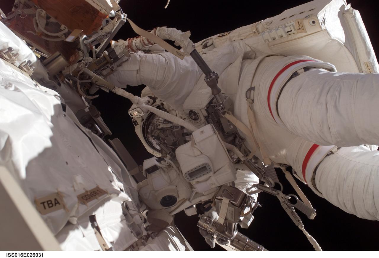
ISS016-E-026031 (30 Jan. 2008) --- Astronaut Peggy Whitson, Expedition 16 commander, participates in a session of extravehicular activity (EVA) as maintenance and construction continue on the International Space Station. During the 7-hour, 10-minute spacewalk, Whitson and astronaut Daniel Tani (out of frame), flight engineer, replaced a motor, known as the Bearing Motor Roll Ring Module (BMRRM), at the base of one of the station's solar wings. The BMRRM is part of the Beta Gimbal Assembly, which experienced electrical failures Dec. 8. A blue and white Earth and the blackness of space provide the backdrop for the scene.
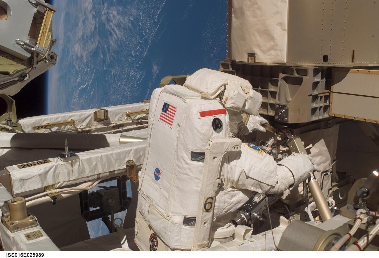
ISS016-E-025989 (30 Jan. 2008) --- Astronaut Peggy Whitson, Expedition 16 commander, participates in a session of extravehicular activity (EVA) as maintenance and construction continue on the International Space Station. During the 7-hour, 10-minute spacewalk, Whitson and astronaut Daniel Tani (out of frame), flight engineer, replaced a motor, known as the Bearing Motor Roll Ring Module (BMRRM), at the base of one of the station's solar wings. The BMRRM is part of the Beta Gimbal Assembly, which experienced electrical failures Dec. 8. A blue and white Earth provides the backdrop for the scene.

ISS016-E-026022 (30 Jan. 2008) --- The face of astronaut Daniel Tani, Expedition 16 flight engineer, is easily recognizable as he participates in a session of extravehicular activity (EVA) as maintenance and construction continue on the International Space Station. During the 7-hour, 10-minute spacewalk, Tani and astronaut Peggy Whitson (out of frame), commander, replaced a motor, known as the Bearing Motor Roll Ring Module (BMRRM), at the base of one of the station's solar wings. The BMRRM is part of the Beta Gimbal Assembly, which experienced electrical failures Dec. 8.
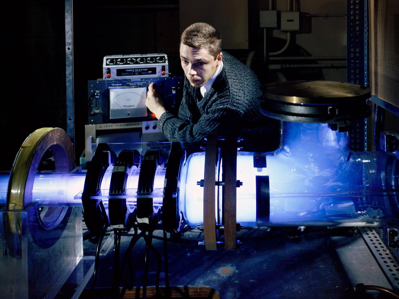
Raymond Palmer, of the Electromagnetic Propulsion Division’s Plasma Flow Section, adjusts the traveling magnetic wave plasma engine being operated in the Electric Power Conversion at the National Aeronautics and Space Administration (NASA) Lewis Research Center. During the 1960s Lewis researchers were exploring several different methods of creating electric propulsion systems, including the traveling magnetic wave plasma engine. The device operated similarly to alternating-current motors, except that a gas, not a solid, was used to conduct the electricity. A magnetic wave induced a current as it passed through the plasma. The current and magnetic field pushed the plasma in one direction. Palmer and colleague Robert Jones explored a variety of engine configurations in the Electric Propulsion Research Building. The engine is seen here mounted externally on the facility’s 5-foot diameter and 16-foot long vacuum tank. The four magnetic coils are seen on the left end of the engine. The researchers conducted two-minute test runs with varying configurations and used of both argon and xenon as the propellant. The Electric Propulsion Research Building was built in 1942 as the Engine Propeller Research Building, often called the Prop House. It contained four test cells to study large reciprocating engines with their propellers. After World War II, the facility was modified to study turbojet engines. By the 1960s, the facility was modified again for electric propulsion research and given its current name.
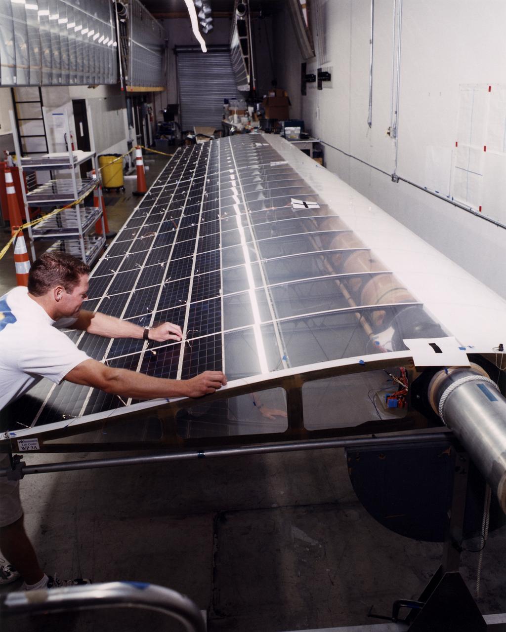
Technician Marshall MacCready carefully lays a panel of solar cells into place on a wing section of the Helios Prototype flying wing at AeroVironment's Design Development Center in Simi Valley, California. The bi-facial cells, manufactured by SunPower, Inc., of Sunnyvale, California, are among 64,000 solar cells which have been installed on the solar-powered aircraft to provide electricity to its 14 motors and operating systems.
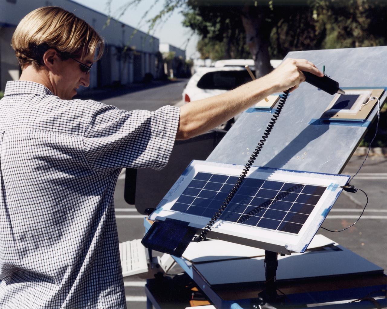
A technician at AeroVironment's Design Development Center in Simi Valley, California, checks a panel of silicon solar cells for conductivity and voltage. The bi-facial cells, fabricated by SunPower, Inc., of Sunnyvale, California, are among 64,000 solar cells which have been installed on the Helios Prototype solar-powered aircraft to provide power to its 14 electric motors and operating systems.
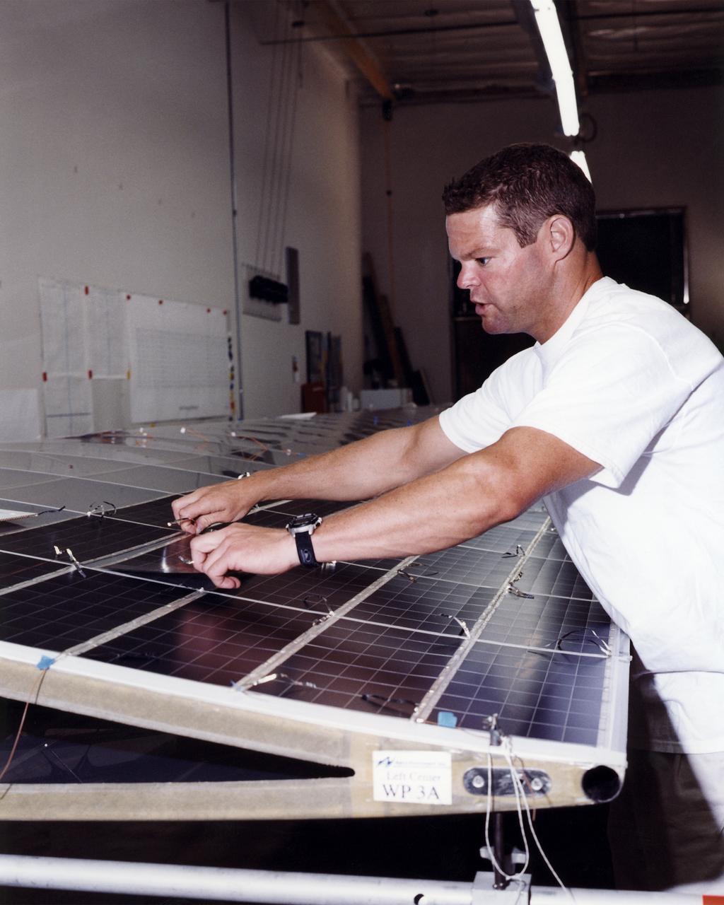
Technician Marshall MacCready carefully lays a panel of solar cells into place on a wing section of the Helios Prototype flying wing at AeroVironment's Design Development Center in Simi Valley, California. More than 1,800 panels containing some 64,000 bi-facial cells, fabricated by SunPower, Inc., of Sunnyvale, California, have been installed on the solar-powered aircraft to provide electricity to its 14 motors and operating systems.
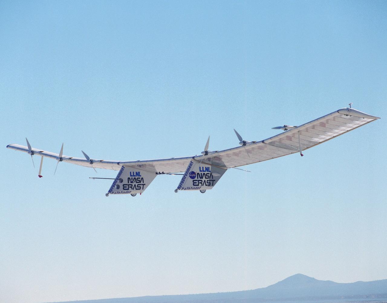
The Pathfinder solar-powered remotely piloted aircraft climbs to a record-setting altitude of 50,567 feet during a flight Sept. 11, 1995, at NASA's Dryden Flight Research Center, Edwards, California. The flight was part of the NASA ERAST (Environmental Research Aircraft and Sensor Technology) program. The Pathfinder was designed and built by AeroVironment Inc., Monrovia, California. Solar arrays cover nearly all of the upper wing surface and produce electricity to power the aircraft's six motors.
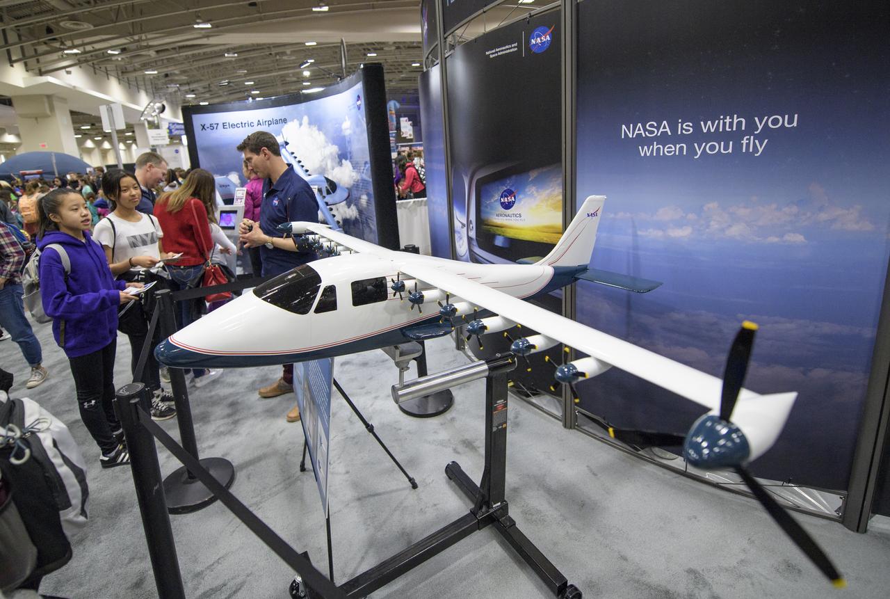
Attendees listen to a NASA staff member speak about the X-57, a research aircraft powered by 14 electric motors, during Sneak Peek Friday at the USA Science and Engineering Festival, Friday, April 6, 2018 at the Walter E. Washington Convention Center in Washington, DC. The festival is open to the public April 7-8. Photo Credit: (NASA/Joel Kowsky)
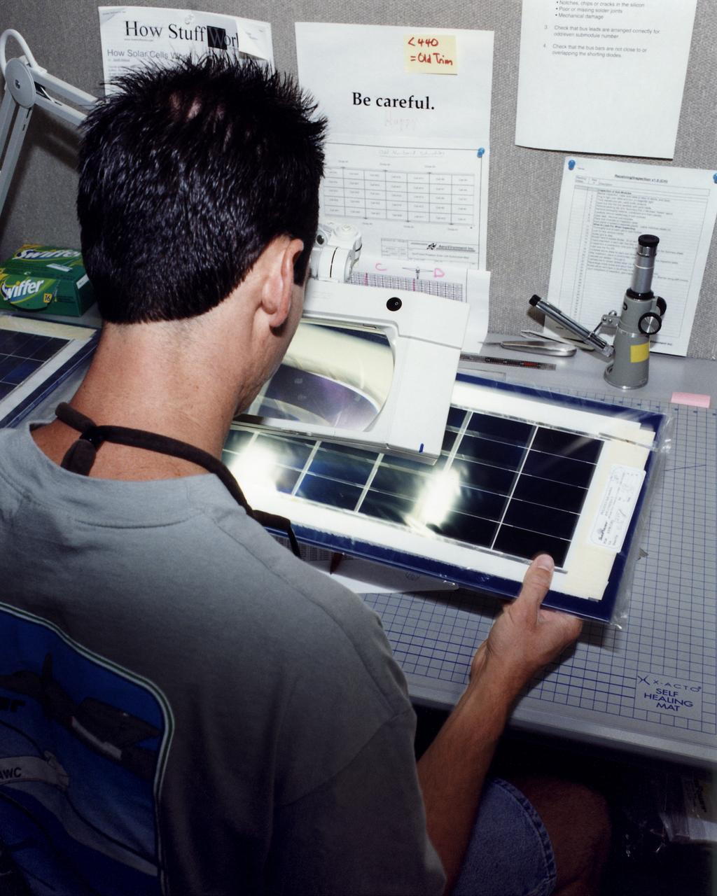
An engineer at AeroVironment's Design Development Center in Simi Valley, California, closely inspects a set of silicon solar cells for potential defects. The cells, fabricated by SunPower, Inc., of Sunnyvale, California, are among 64,000 solar cells which have been installed on the Helios Prototype solar-powered aircraft to provide power to its 14 electric motors and operating systems.
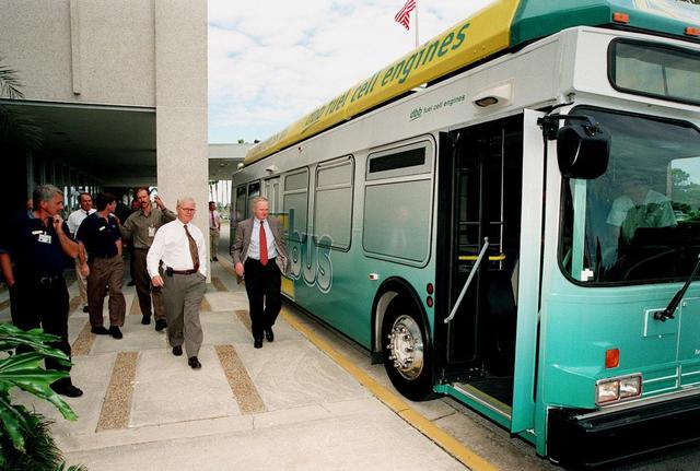
KSC workers, with Center Director Roy Bridges (at right next to bus), head for the open door of the Zero Emissions (ZE) transit bus and a ride around the center. Provided by dbb fuel cell engines inc. of Vancouver, Canada, the ZE bus was brought to KSC as part of the Center's Alternative Fuel Initiatives Program. The bus uses a Proton Exchange Membrane fuel cell in which hydrogen and oxygen, from atmospheric air, react to produce electricity that powers an electric motor drive system. The by-product "exhaust" from the fuel cell is water vapor, thus zero harmful emissions. A typical diesel-powered bus emits more than a ton of harmful pollutants from its exhaust every year. Available to employees for viewing and a ride, the ZE bus is also being used on tour routes at the KSC Visitor Complex Oct. 26-27
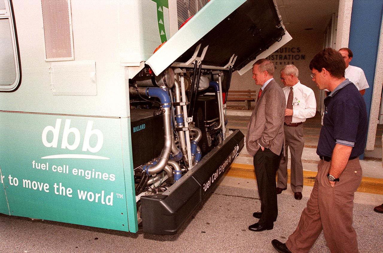
In front of the Headquarters Building at KSC, Center Director Roy Bridges (left) looks at the hydrogen-oxygen driven engine powering a Zero Emissions (ZE) transit bus. Provided by dbb fuel cell engines inc. of Vancouver, Canada, the ZE bus was brought to KSC as part of the Center's Alternative Fuel Initiatives Program. The bus uses a Proton Exchange Membrane fuel cell in which hydrogen and oxygen, from atmospheric air, react to produce electricity that powers an electric motor drive system. The by-product "exhaust" from the fuel cell is water vapor, thus zero harmful emissions. A typical diesel-powered bus emits more than a ton of harmful pollutants from its exhaust every year. Available for viewing by employees, the ZE bus is also being used on tour routes at the KSC Visitor Complex Oct. 26-27
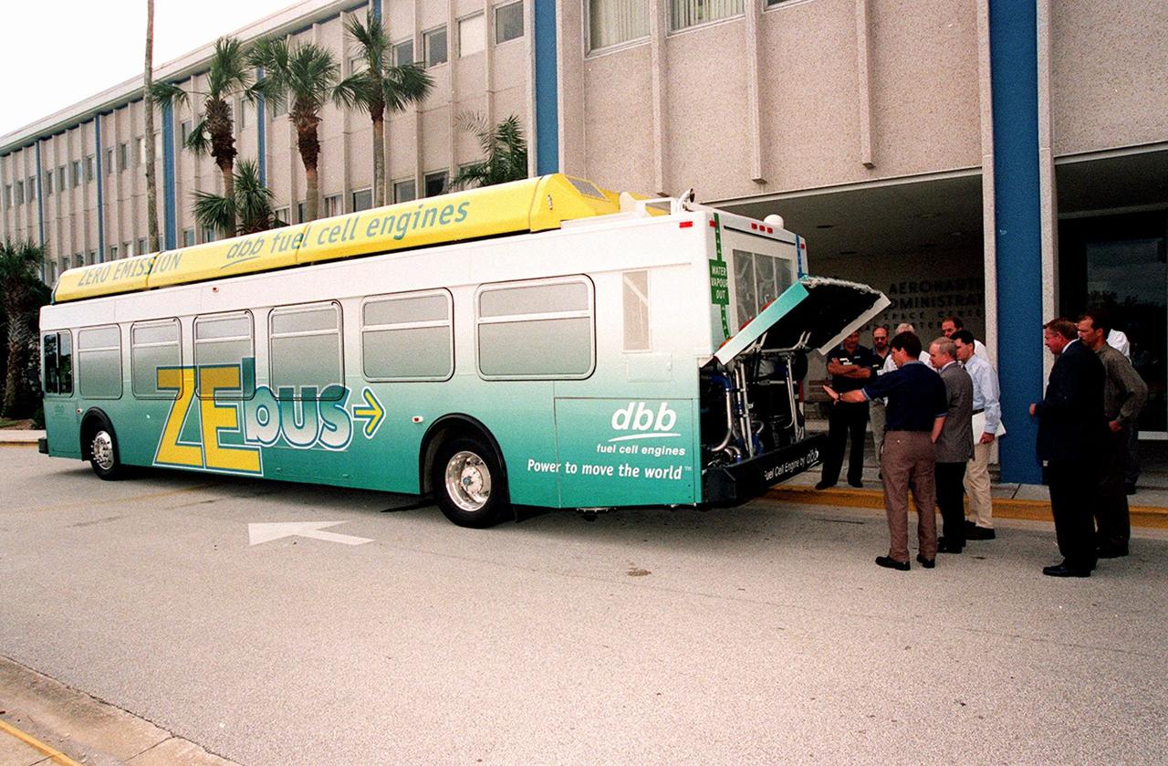
On view in front of the Headquarters Building, the Zero Emissions (ZE) transit bus attracts an interested group of employees, including Center Director Roy Bridges (second from left in foreground). Provided by dbb fuel cell engines inc. of Vancouver, Canada, the ZE bus was brought to KSC as part of the Center's Alternative Fuel Initiatives Program. The bus uses a Proton Exchange Membrane fuel cell in which hydrogen and oxygen, from atmospheric air, react to produce electricity that powers an electric motor drive system. The by-product "exhaust" from the fuel cell is water vapor, thus zero harmful emissions. A typical diesel-powered bus emits more than a ton of harmful pollutants from its exhaust every year. Available for viewing by employees, the ZE bus is also being used on tour routes at the KSC Visitor Complex Oct. 26-27
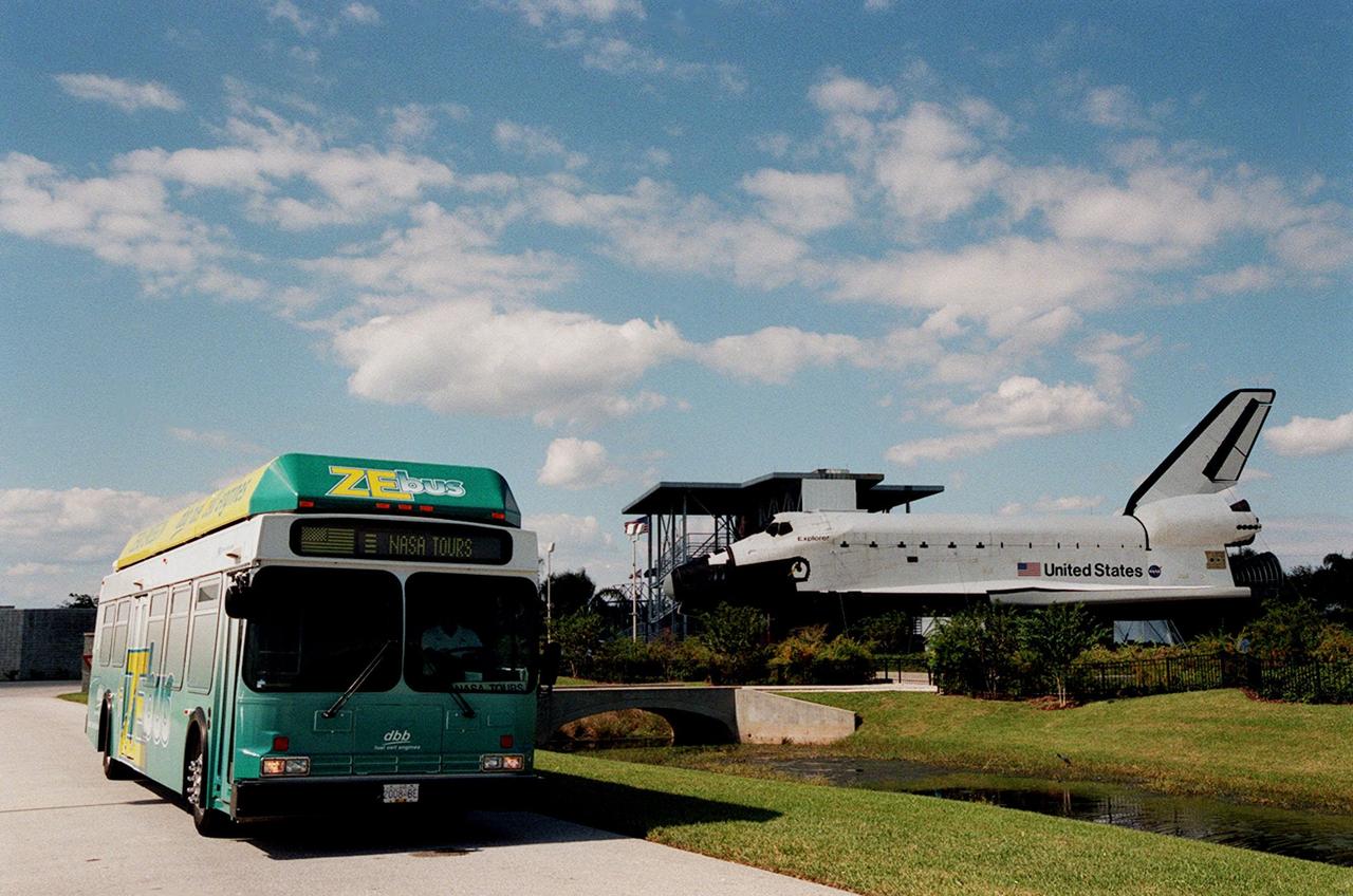
The Zero Emissions (ZE) transit bus passes a mock-up orbiter named Explorer on a trek through the KSC Visitor Complex. Provided by dbb fuel cell engines inc. of Vancouver, Canada, the ZE bus was brought to KSC as part of the Center's Alternative Fuel Initiatives Program. The bus uses a Proton Exchange Membrane fuel cell in which hydrogen and oxygen, from atmospheric air, react to produce electricity that powers an electric motor drive system. The by-product "exhaust" from the fuel cell is water vapor, thus zero harmful emissions. A typical diesel-powered bus emits more than a ton of harmful pollutants from its exhaust every year. The ZE bus is being used on tour routes at the KSC Visitor Complex for two days to introduce the public to the concept
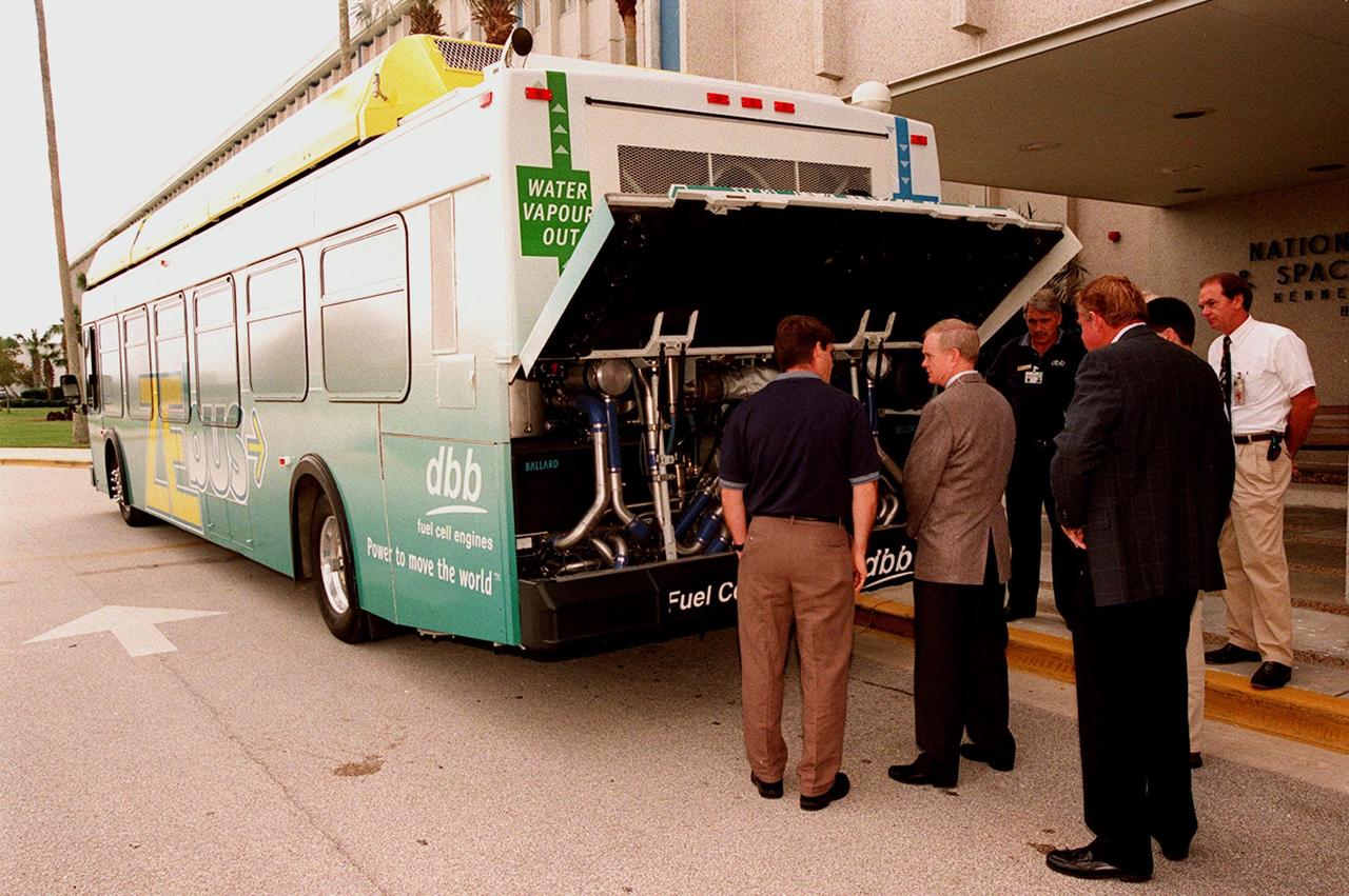
KSC employees, along with Center Director Roy Bridges (second from left), view the hydrogen-oxygen driven engine powering a Zero Emissions (ZE) transit bus. Provided by dbb fuel cell engines inc. of Vancouver, Canada, the ZE bus was brought to KSC as part of the Center's Alternative Fuel Initiatives Program. The bus uses a Proton Exchange Membrane fuel cell in which hydrogen and oxygen, from atmospheric air, react to produce electricity that powers an electric motor drive system. The by-product "exhaust" from the fuel cell is water vapor, thus zero harmful emissions. A typical diesel-powered bus emits more than a ton of harmful pollutants from its exhaust every year. Available for viewing by employees, the ZE bus is also being used on tour routes at the KSC Visitor Complex Oct. 26-27
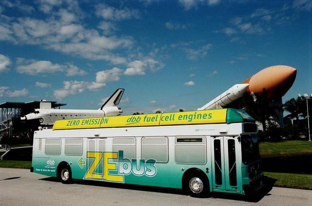
The Zero Emissions (ZE) transit bus tours the KSC Visitor Complex for a test ride. In the background are a mock-up orbiter named Explorer (left) and a stack of solid rocket boosters and external tank (right), typically used on Shuttle launches. Provided by dbb fuel cell engines inc. of Vancouver, Canada, the ZE bus was brought to KSC as part of the Center's Alternative Fuel Initiatives Program. The bus uses a Proton Exchange Membrane fuel cell in which hydrogen and oxygen, from atmospheric air, react to produce electricity that powers an electric motor drive system. The by-product "exhaust" from the fuel cell is water vapor, thus zero harmful emissions. A typical diesel-powered bus emits more than a ton of harmful pollutants from its exhaust every year. The ZE bus is being used on tour routes at the KSC Visitor Complex for two days to introduce the public to the concept
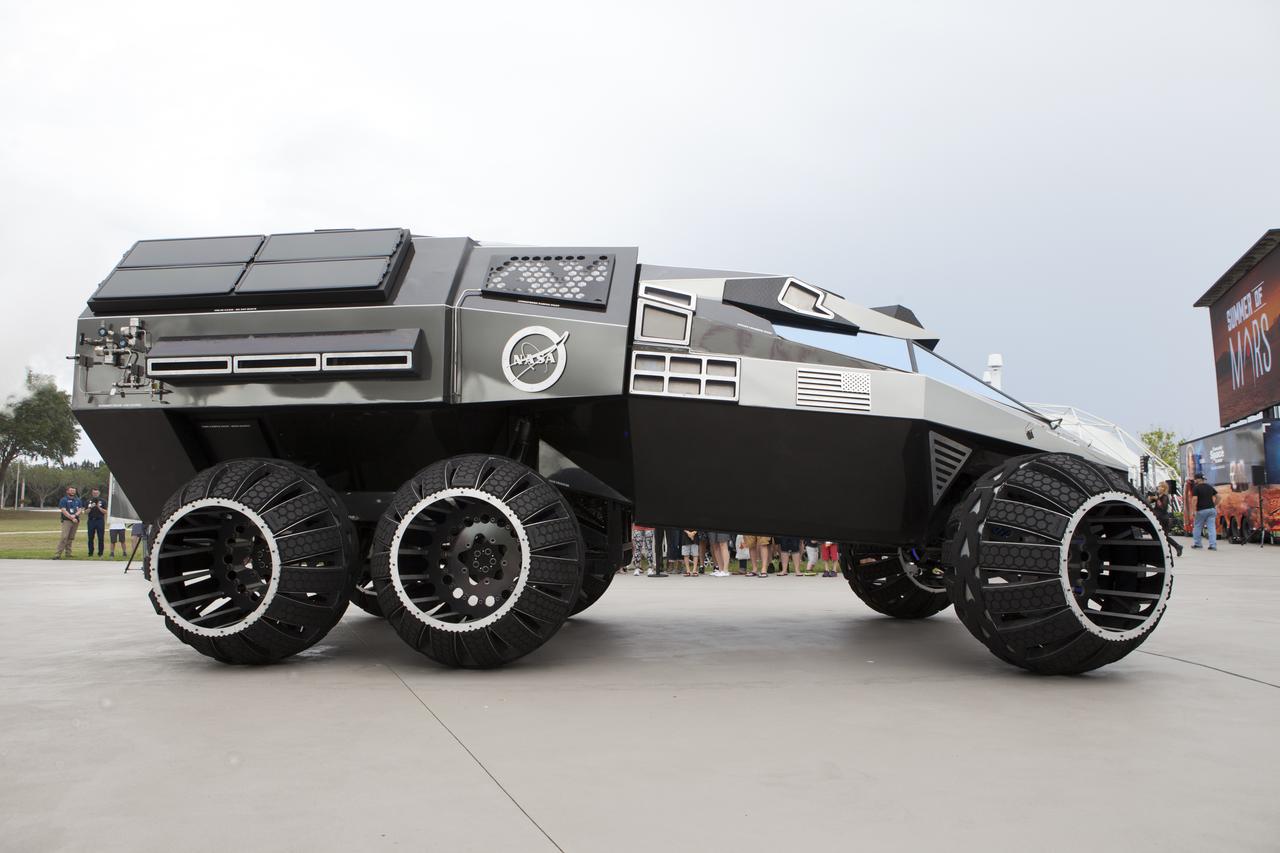
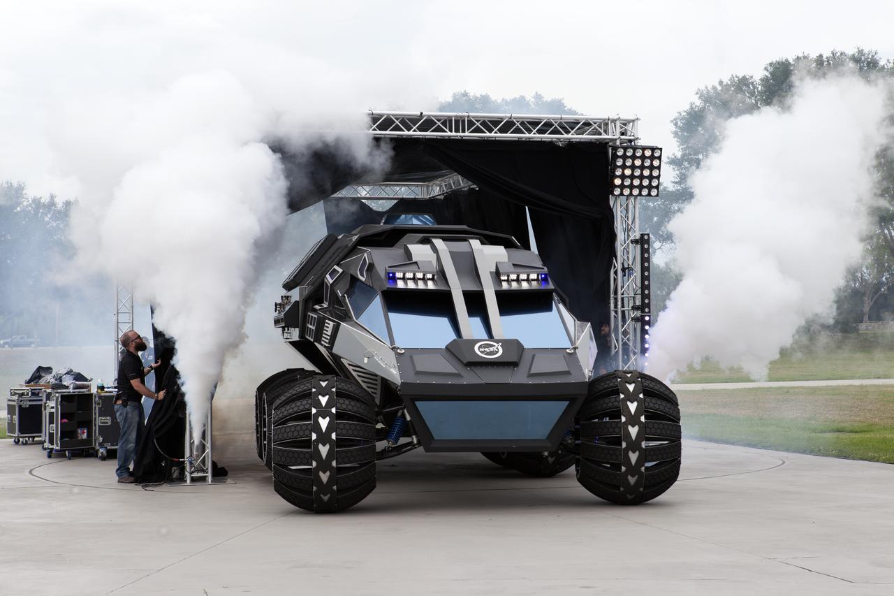
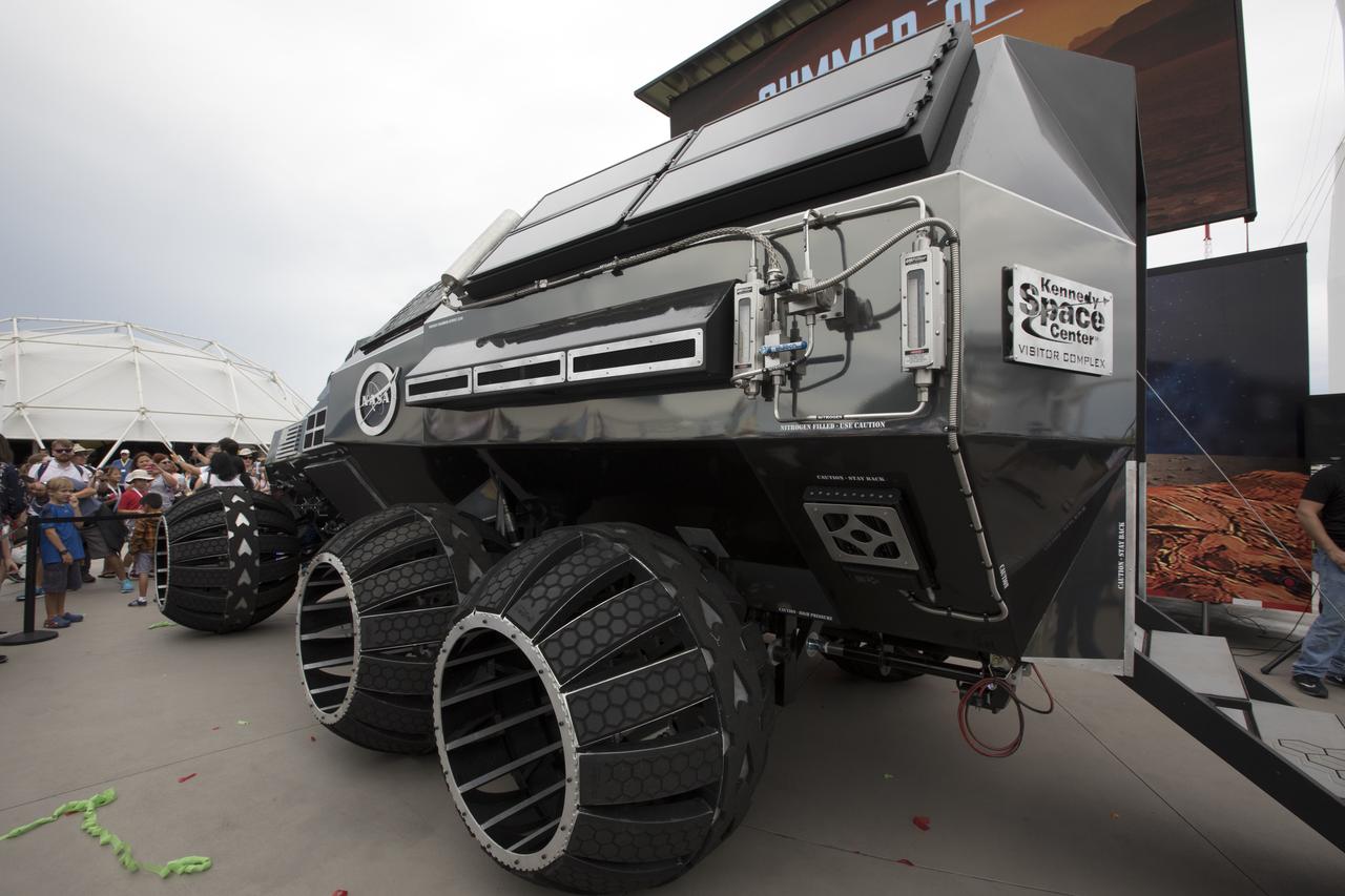
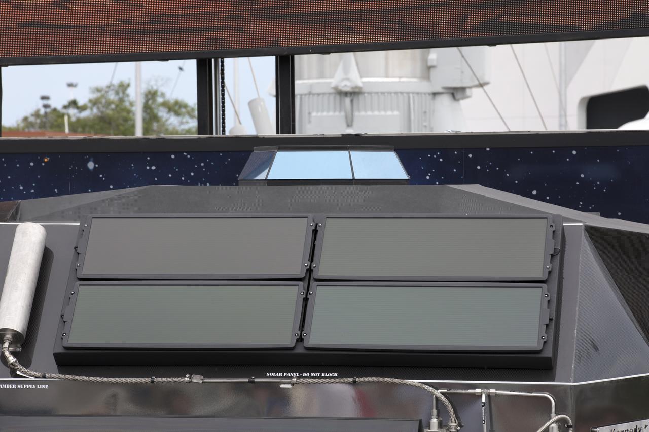
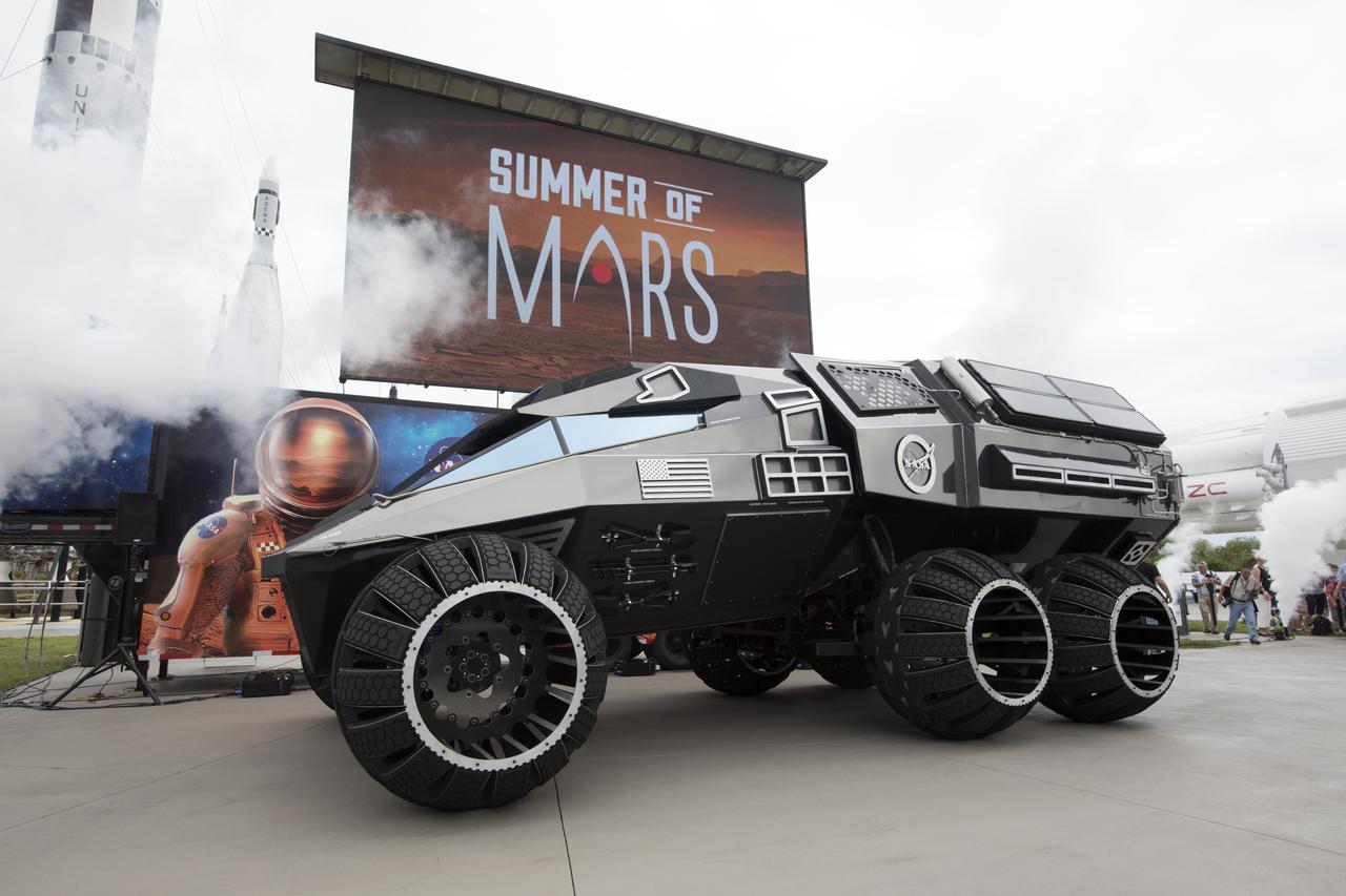
The scientifically-themed Mars rover concept vehicle operates on an electric motor, powered by solar panels and a 700-volt battery. The rover separates in the middle with the front area designed for scouting and equipped with a radio and navigation provided by the Global Positioning System. The back section serves as a full laboratory which can disconnect for autonomous research. The "Summer of Mars" promotion is designed to provide guests with a better understanding of NASA's studies of the Red Planet. The builders of the rover, Parker Brothers Concepts of Port Canaveral, Florida, incorporated input into its design from NASA subject matter experts.
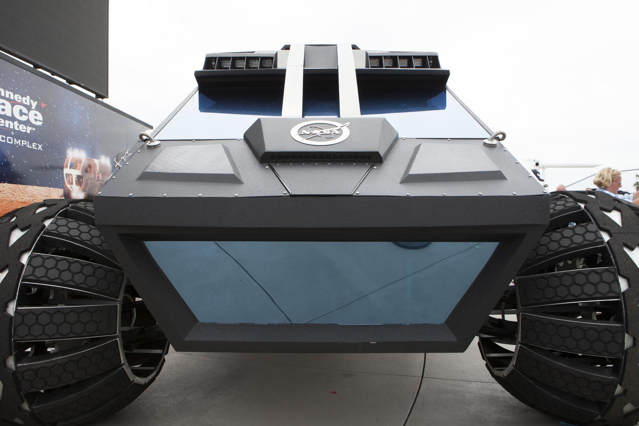
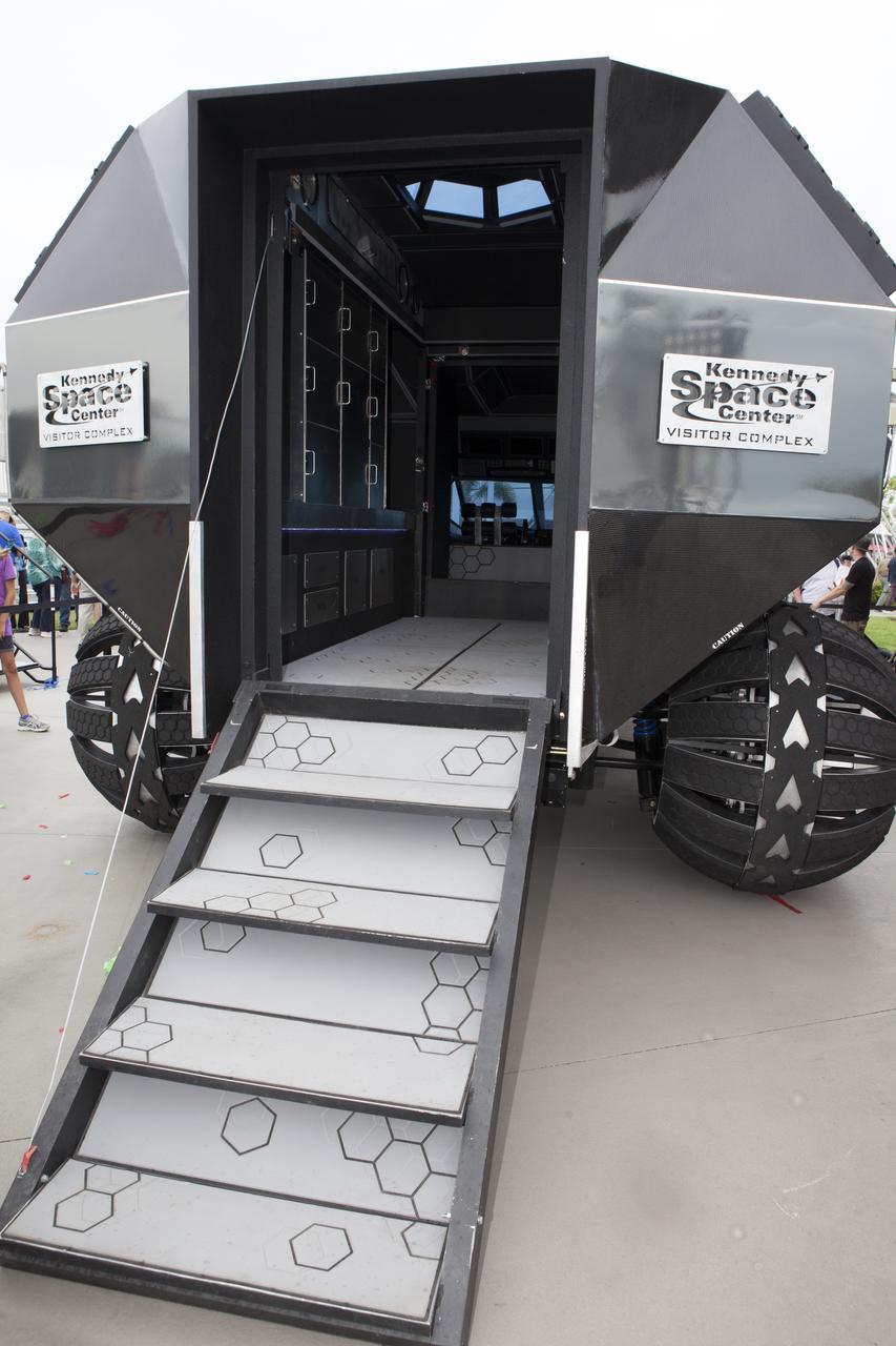
The scientifically-themed Mars rover concept vehicle operates on an electric motor, powered by solar panels and a 700-volt battery. The back section opens and serves as a laboratory which can disconnect for autonomous research. While this exact rover is not expected to operate on Mars, one or more of its elements could make its way into a rover astronauts will drive on the Red Planet. The "Summer of Mars" promotion is designed to provide guests with a better understanding of NASA's studies of the Red Planet. The builders of the rover, Parker Brothers Concepts of Port Canaveral, Florida, incorporated input into its design from NASA subject matter experts.
The scientifically-themed Mars rover concept vehicle operates on an electric motor, powered by solar panels and a 700-volt battery. The rover separates in the middle with the front area designed for scouting and equipped with a radio and navigation provided by the Global Positioning System. The back section serves as a full laboratory which can disconnect for autonomous research. The "Summer of Mars" promotion is designed to provide guests with a better understanding of NASA's studies of the Red Planet. The builders of the rover, Parker Brothers Concepts of Port Canaveral, Florida, incorporated input into its design from NASA subject matter experts.
The scientifically-themed Mars rover concept vehicle operates on an electric motor, powered by solar panels and a 700-volt battery. The back section opens and serves as a laboratory which can disconnect for autonomous research. While this exact rover is not expected to operate on Mars, one or more of its elements could make its way into a rover astronauts will drive on the Red Planet. The "Summer of Mars" promotion is designed to provide guests with a better understanding of NASA's studies of the Red Planet. The builders of the rover, Parker Brothers Concepts of Port Canaveral, Florida, incorporated input into its design from NASA subject matter experts.
The scientifically-themed Mars rover concept vehicle operates on an electric motor, powered by solar panels and a 700-volt battery. The back section opens and serves as a laboratory which can disconnect for autonomous research. While this exact rover is not expected to operate on Mars, one or more of its elements could make its way into a rover astronauts will drive on the Red Planet. The "Summer of Mars" promotion is designed to provide guests with a better understanding of NASA's studies of the Red Planet. The builders of the rover, Parker Brothers Concepts of Port Canaveral, Florida, incorporated input into its design from NASA subject matter experts.
The scientifically-themed Mars rover concept vehicle operates on an electric motor, powered by solar panels and a 700-volt battery. The rover separates in the middle with the front area designed for scouting and equipped with a radio and navigation provided by the Global Positioning System. The back section serves as a full laboratory which can disconnect for autonomous research. The "Summer of Mars" promotion is designed to provide guests with a better understanding of NASA's studies of the Red Planet. The builders of the rover, Parker Brothers Concepts of Port Canaveral, Florida, incorporated input into its design from NASA subject matter experts.
The scientifically-themed Mars rover concept vehicle operates on an electric motor, powered by solar panels and a 700-volt battery. The back section opens and serves as a laboratory which can disconnect for autonomous research. While this exact rover is not expected to operate on Mars, one or more of its elements could make its way into a rover astronauts will drive on the Red Planet. The "Summer of Mars" promotion is designed to provide guests with a better understanding of NASA's studies of the Red Planet. The builders of the rover, Parker Brothers Concepts of Port Canaveral, Florida, incorporated input into its design from NASA subject matter experts.

New wooden fan blades being prepared for installation in the Altitude Wind Tunnel at the National Advisory Committee for Aeronautics (NACA) Lewis Flight Propulsion Laboratory. The facility underwent a major upgrade in 1951 to increase its operating capacities in order to handle the new, more powerful turbojet engines being manufactured in the 1950s. The fan blades were prepared in the shop area, seen in this photograph, before being lowered through a hole in the tunnel and attached to the drive shaft. A new drive bearing and tail faring were also installed on the fan as part of this rehab project. A 12-bladed 31-foot-diameter spruce wood fan generated the 300 to 500 mile-per-hour airflow through the tunnel. An 18,000-horsepower General Electric induction motor located in the rear corner of the Exhauster Building drove the fan at 410 revolutions per minute. An extension shaft, sealed in the tunnel’s shell with flexible couplings that allowed for the movement of the shell, connected the motor to the fan. A bronze screen secured to the turning vanes protected the fan against damage from any engine parts sailing through the tunnel. Despite this screen the blades did become worn or cracked over time and had to be replaced.
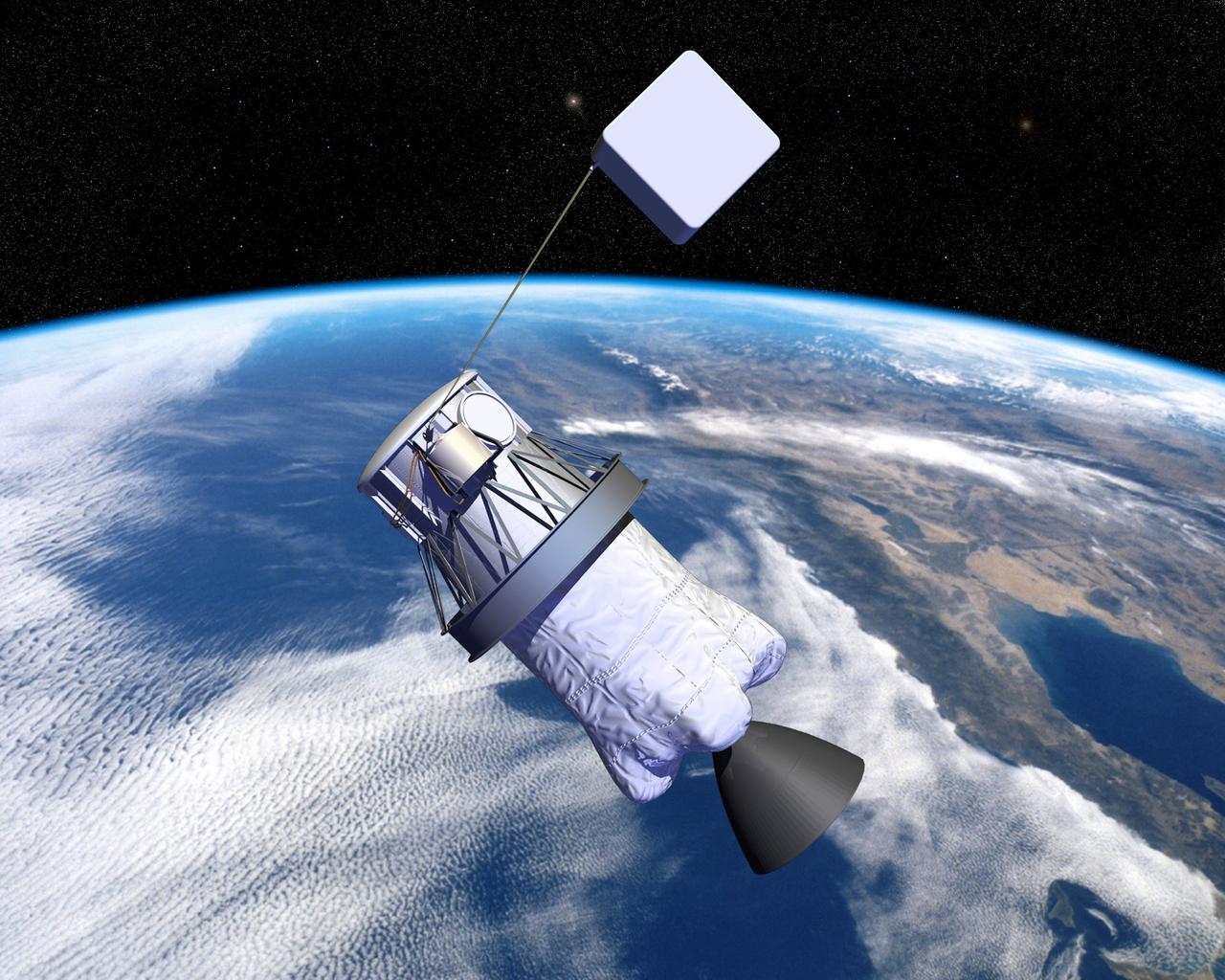
Pictured is an artist's concept of NASA's Propulsive Small Expendable Deployer System experiment (ProSEDS). ProSEDS will demonstrate the use of an electrodynamic tether, basically a long, thin wire, for propulsion. An electrodynamic tether uses the same principles as electric motors in toys, appliances and computer disk drives, and generators in automobiles and power plants. When electrical current is flowing through the tether, a magnetic field is produced that pushes against the magnetic field of the Earth. For ProSEDS, the current in the tether results by virtue of the voltage generated when the tether moves through the Earth's magnetic field at more than 17,000 mph. This approach can produce drag thrust generating useable power. Since electrodynamic tethers require no propellant, they could substantially reduce the weight of the spacecraft and provide a cost-effective method of reboosting spacecraft. The initial flight of ProSEDS is scheduled to fly aboard an Air Force Delta II rocket in summer of 2002. In orbit, ProSEDS will deploy from a Delta II second stage. It will be a 3.1-mile (5 kilometer) long, ultrathin base-wire tether cornected with a 6.2-mile (10 kilometer) long nonconducting tether. The ProSEDS experiment is managed by the Space Transportation Directorate at the Marshall Space Flight Center.
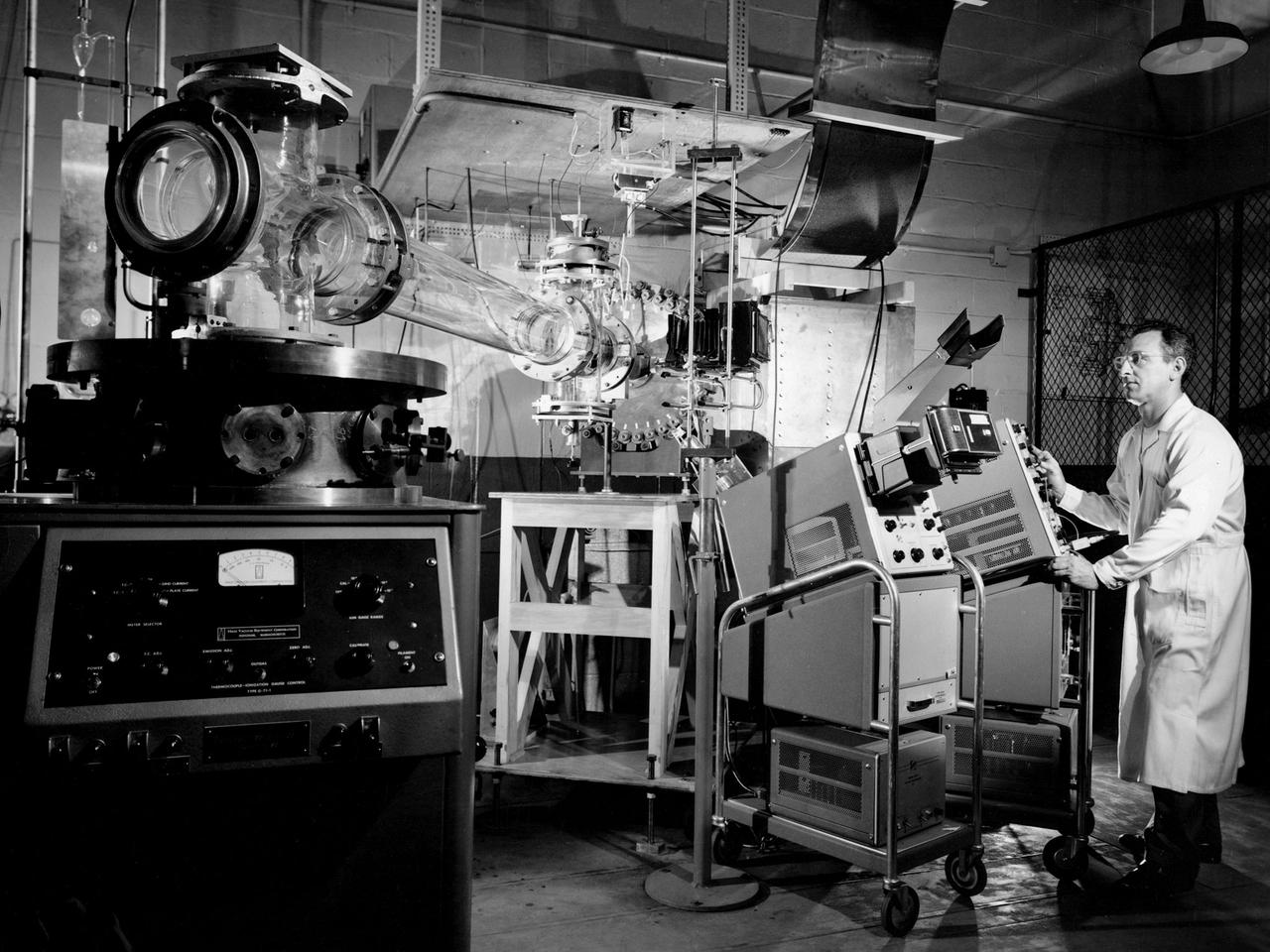
Researcher Charles Michels operates a coaxial plasma gun rig in Cell SW-13 of the Engine Research Building at the National Aeronautics and Space Administration (NASA) Lewis Research Center. From 1962 to 1967 NASA Lewis investigated coaxial plasma guns powered by conventional capacitor banks. The studies were part of a larger effort to identify electromagnetic accelerators for space propulsion. NASA worked with General Dynamics, General Electric, General Motors, and Republic Aviation on the project. NASA Lewis conducted a research program to determine which factors influenced the coaxial gun’s efficiency and analyze the acceleration process. The system had not previously been used for propulsion applications. The single-shot gun’s fast gas valve and capacitor banks with variable-delay ignition source permitted the evaluation of gun performance under controllable propellant quantity and distribution conditions. The coaxial plasma gun was the most basic type of electromagnetic accelerator. It included a charged capacitor in series with a pair of coaxial electrodes. An electrical breakdown occurred when gas was admitted to the inter-electrode region. The gas instantly became a good conductor and formed a conducting sheet that separated the magnetic field from the open region beyond. The highly-conducting gas was basically expelled by the force of the magnetic pressure. This type of thruster could operate at the high instantaneous power levels without decreasing its average power level.
NASA's Propulsive Small Expendable Deployer System experiment (ProSEDS) will demonstrate the use of an electrodynamic tether, basically a long, thin wire, for propulsion. An electrodynamic tether uses the same principles as electric motors in toys, appliances and computer disk drives, and generators in automobiles and power plants. When electrical current is flowing through the tether, a magnetic field is produced that pushes against the magnetic field of the Earth. For ProSEDS, the current in the tether results by virtue of the voltage generated when the tether moves through the Earth's magnetic field at more than 17,000 mph. This approach can produce drag thrust generating useable power. Since electrodynamic tethers require no propellant, they could substantially reduce the weight of the spacecraft and provide a cost-effective method of reboosting spacecraft. The initial flight of ProSEDS is scheduled to fly aboard an Air Force Delta II rocket in the summer of 2002. In orbit, ProSEDS will deploy from a Delta II second stage. It will be a 3.1-mile (5 kilometer) long, ultrathin base-wire cornected with a 6.2-mile (10 kilometer) long nonconducting tether. This photograph shows Less Johnson, a scientist at MSFC inspecting the nonconducting part of a tether as it exits a deployer similar to the one to be used in the ProSEDS experiment. The ProSEDS experiment is managed by the Space Transportation Directorate at MSFC.
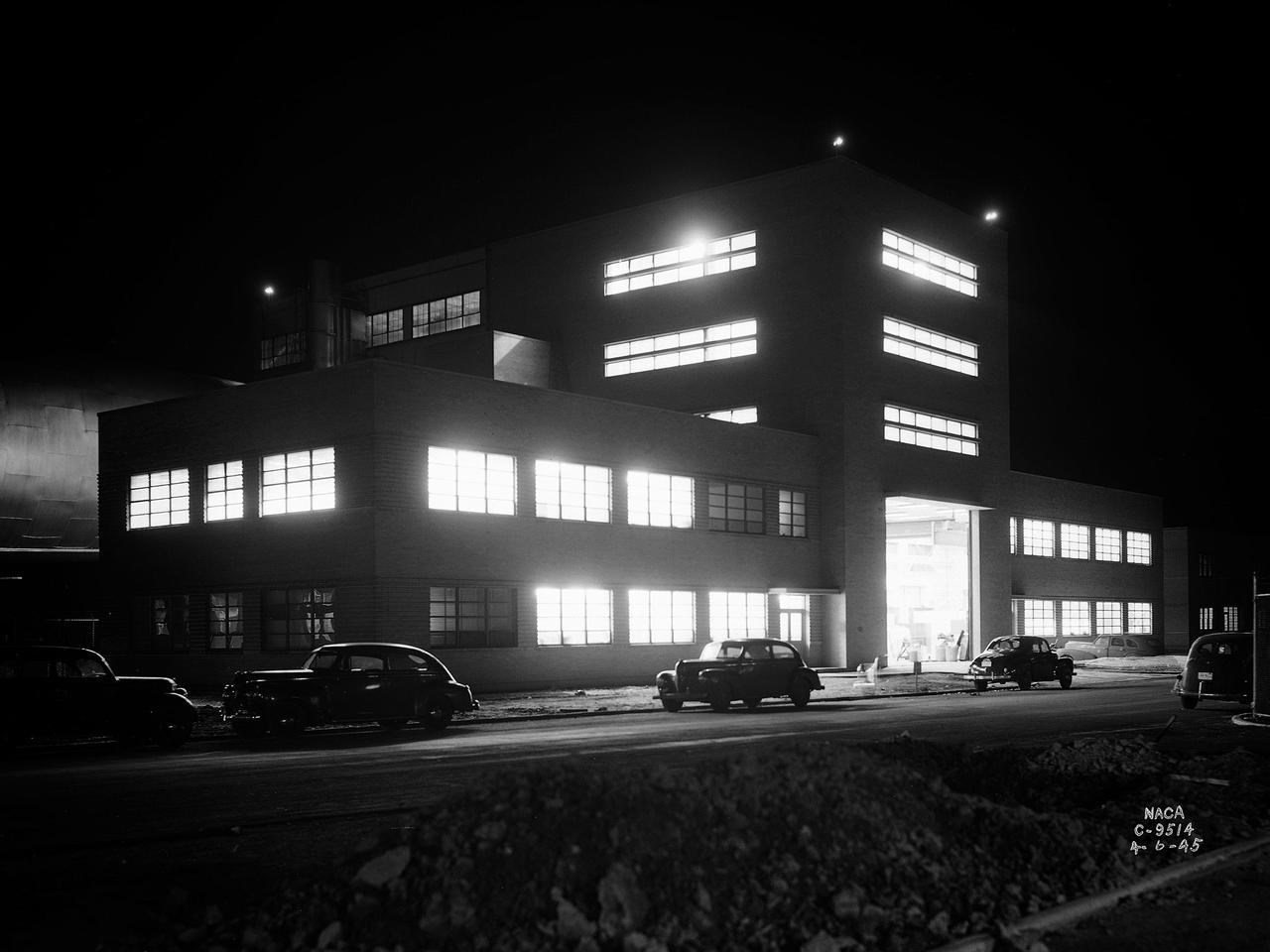
The Altitude Wind Tunnel (AWT) during one of its overnight runs at the National Advisory Committee for Aeronautics (NACA) Aircraft Engine Research Laboratory in Cleveland, Ohio. The AWT was run during night hours so that its massive power loads were handled when regional electric demands were lowest. At the time the AWT was among the most complex wind tunnels ever designed. In order to simulate conditions at high altitudes, NACA engineers designed innovative new systems that required tremendous amounts of electricity. The NACA had an agreement with the local electric company that it would run its larger facilities overnight when local demand was at its lowest. In return the utility discounted its rates for the NACA during those hours. The AWT could produce wind speeds up to 500 miles per hour through its 20-foot-diameter test section at the standard operating altitude of 30,000 feet. The airflow was created by a large fan that was driven by an 18,000-horsepower General Electric induction motor. The altitude simulation was accomplished by large exhauster and refrigeration systems. The cold temperatures were created by 14 Carrier compressors and the thin atmosphere by four 1750-horsepower exhausters. The first and second shifts usually set up and broke down the test articles, while the third shift ran the actual tests. Engineers would often have to work all day, then operate the tunnel overnight, and analyze the data the next day. The night crew usually briefed the dayshift on the tests during morning staff meetings.

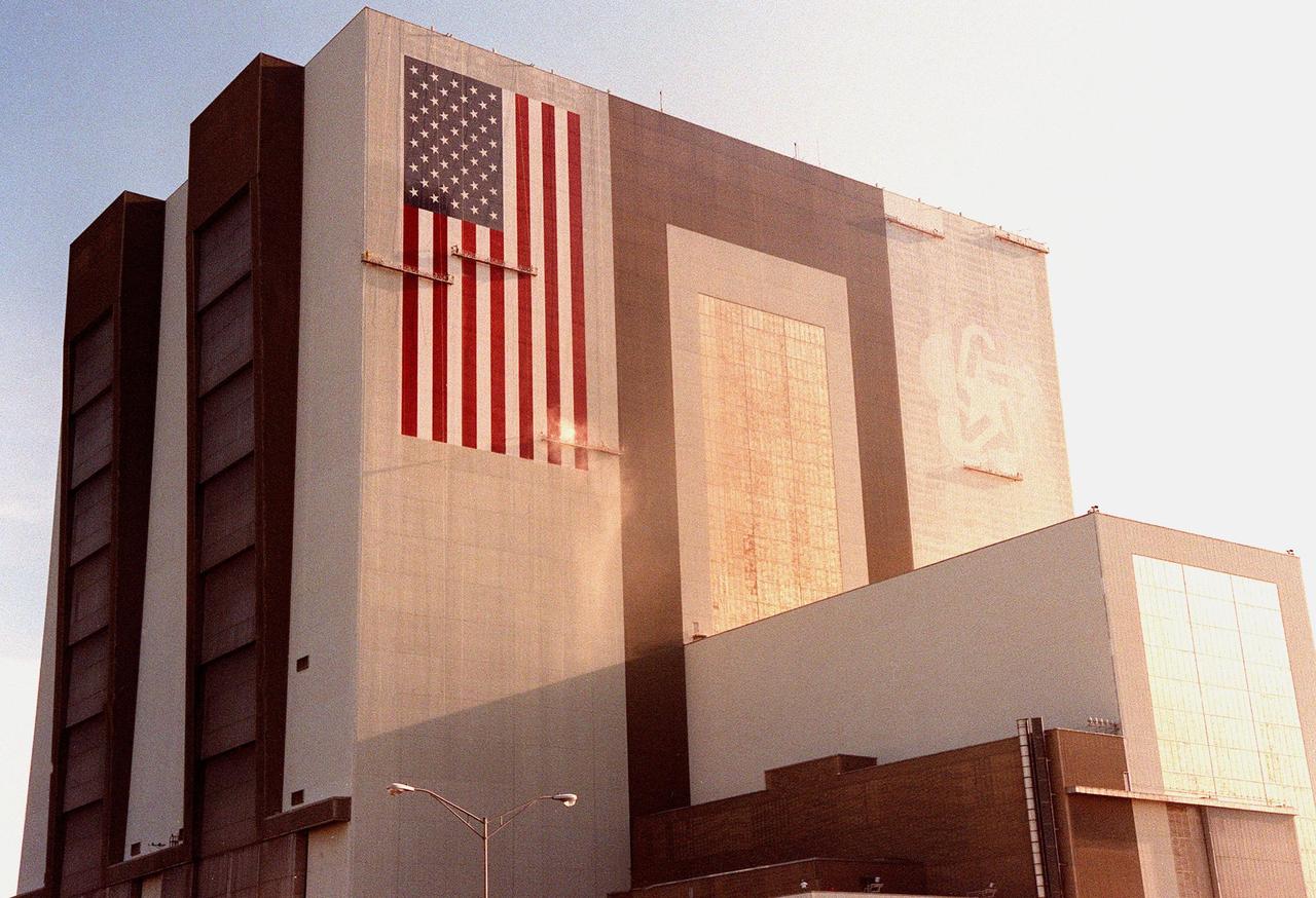
Painters are suspended on platforms from the top of the 525-foot-high Vehicle Assembly Building (VAB) at KSC during repainting of the American flag. The flag spans an area 209 feet by 110 feet and will require 510 gallons of red, white and blue paint. Each stripe of the flag is 9 feet wide and each star is 6 feet in diameter. The platforms are operated by two electric motors and travel 35 feet per minute. Work is being done with rollers, with brushes being used for details. The paint was donated by ICI Devoe of Louisville, Ky. In addition to the flag, the Bicentennial Emblem on the other side of the VAB doors is being replaced by the NASA logo, honoring NASA’s 40th anniversary (in October). The logo covers an area 110 feet by 132 feet. Work is expected to be completed in mid-September

KENNEDY SPACE CENTER, FLA. -- Painters are suspended on platforms from the top of the 525-foot-high Vehicle Assembly Building (VAB) at KSC during repainting of the American flag and NASA logo. The flag spans an area 209 feet by 110 feet, or about 23,437 square feet, and will require 510 gallons of red, white and blue paint. Each stripe of the flag is 9 feet wide and each star is 6 feet in diameter. The previous Bicentennial Emblem on the right side of the VAB doors is being replaced by the NASA logo, honoring NASA’s 40th anniversary (in October). The logo will cover an area 110 feet by 132 feet, or about 12,300 square feet. The painting platforms are operated by two electric motors and travel 35 feet per minute. Work is being done with rollers, with brushes being used for details. The paint was donated by ICI Devoe of Louisville, Ky. Work is expected to be completed in mid-September
Painters are suspended on platforms from the top of the 525-foot-high Vehicle Assembly Building (VAB) at KSC during repainting of the American flag and NASA logo. The flag spans an area 209 feet by 110 feet and will require 510 gallons of red, white and blue paint. Each stripe of the flag is 9 feet wide and each star is 6 feet in diameter. The previous Bicentennial Emblem on the other side of the VAB doors is being replaced by the NASA logo, honoring NASA’s 40th anniversary (in October). The logo covers an area 110 feet by 132 feet. The painting platforms are operated by two electric motors and travel 35 feet per minute. Work is being done with rollers, with brushes being used for details. The paint was donated by ICI Devoe of Louisville, Ky. Work is expected to be completed in mid-September