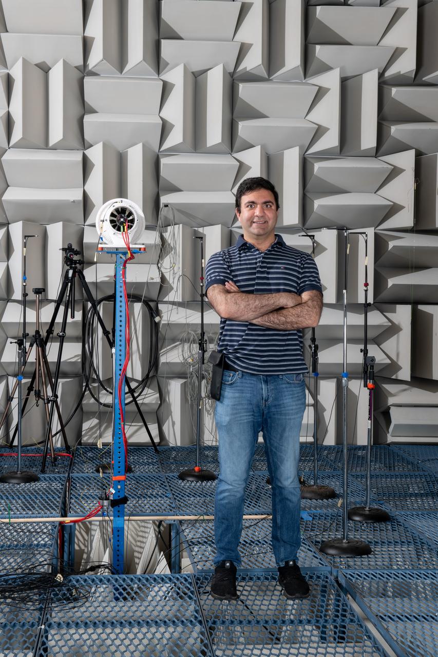
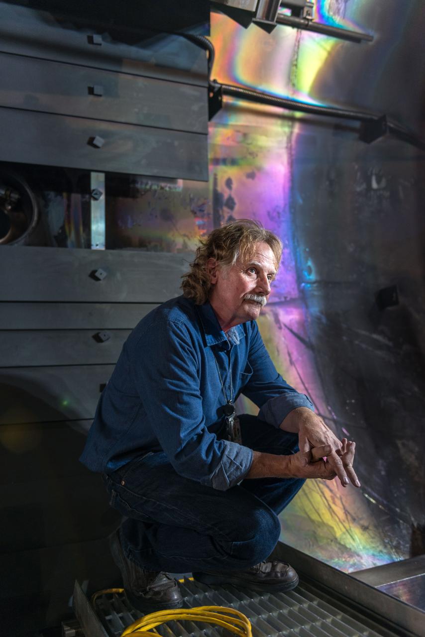
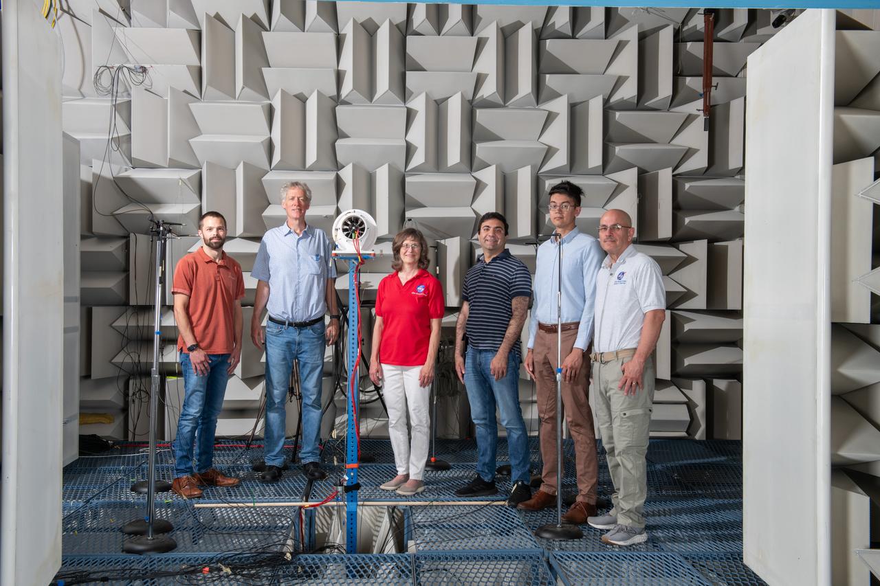
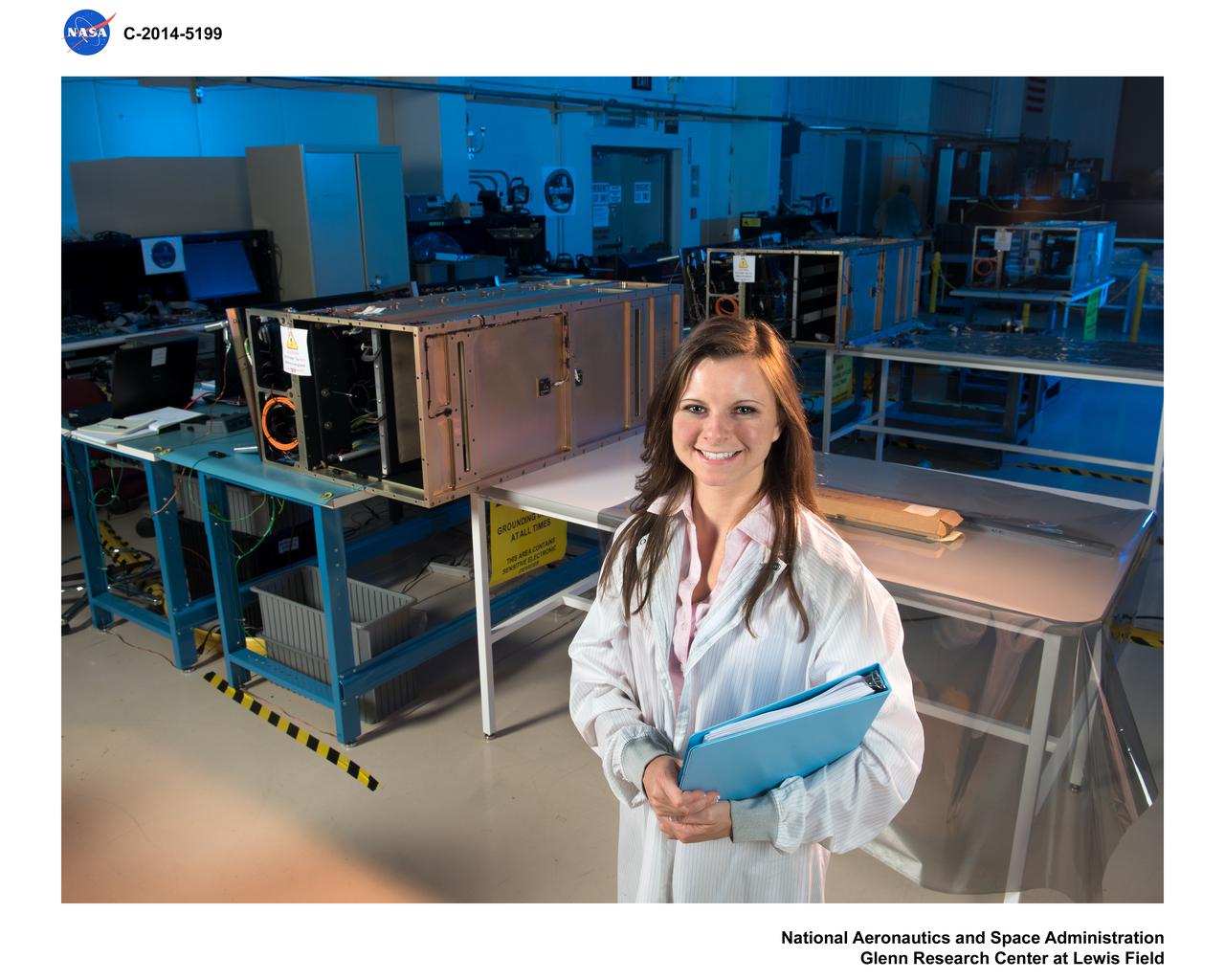
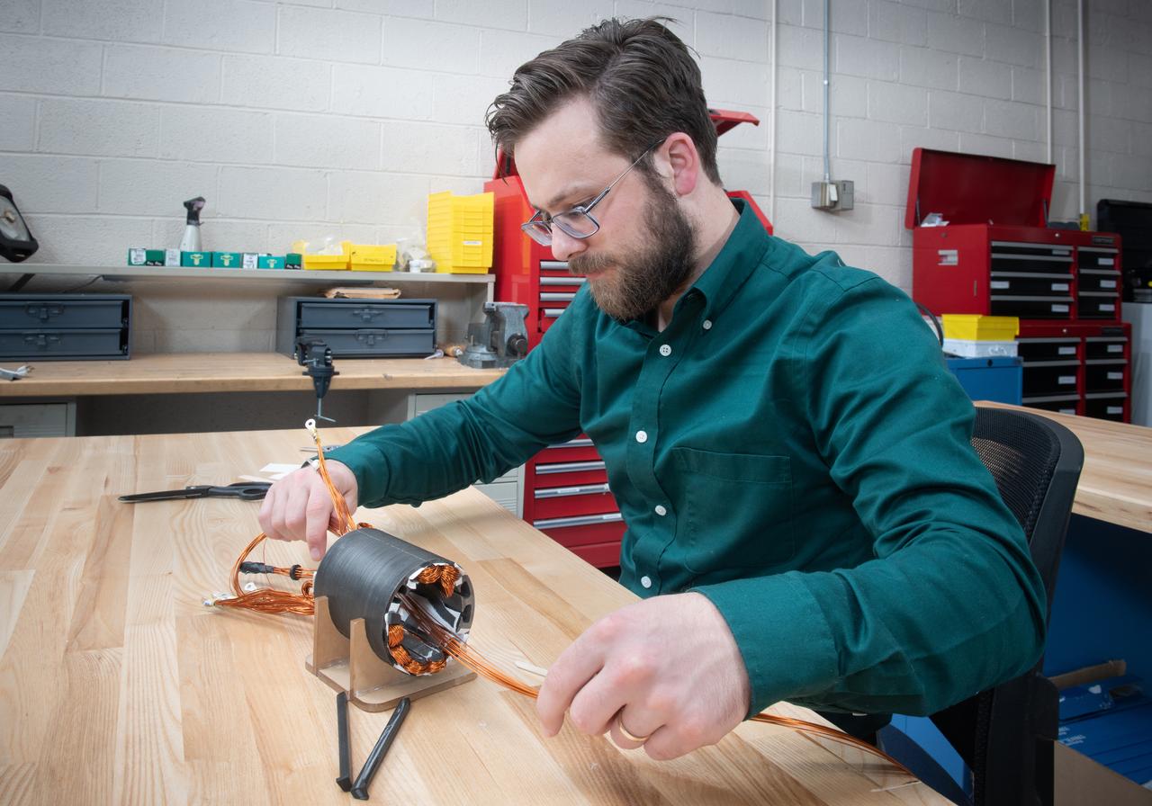
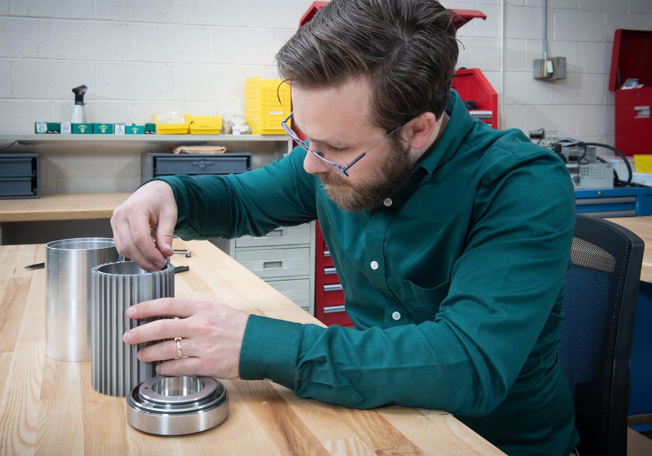
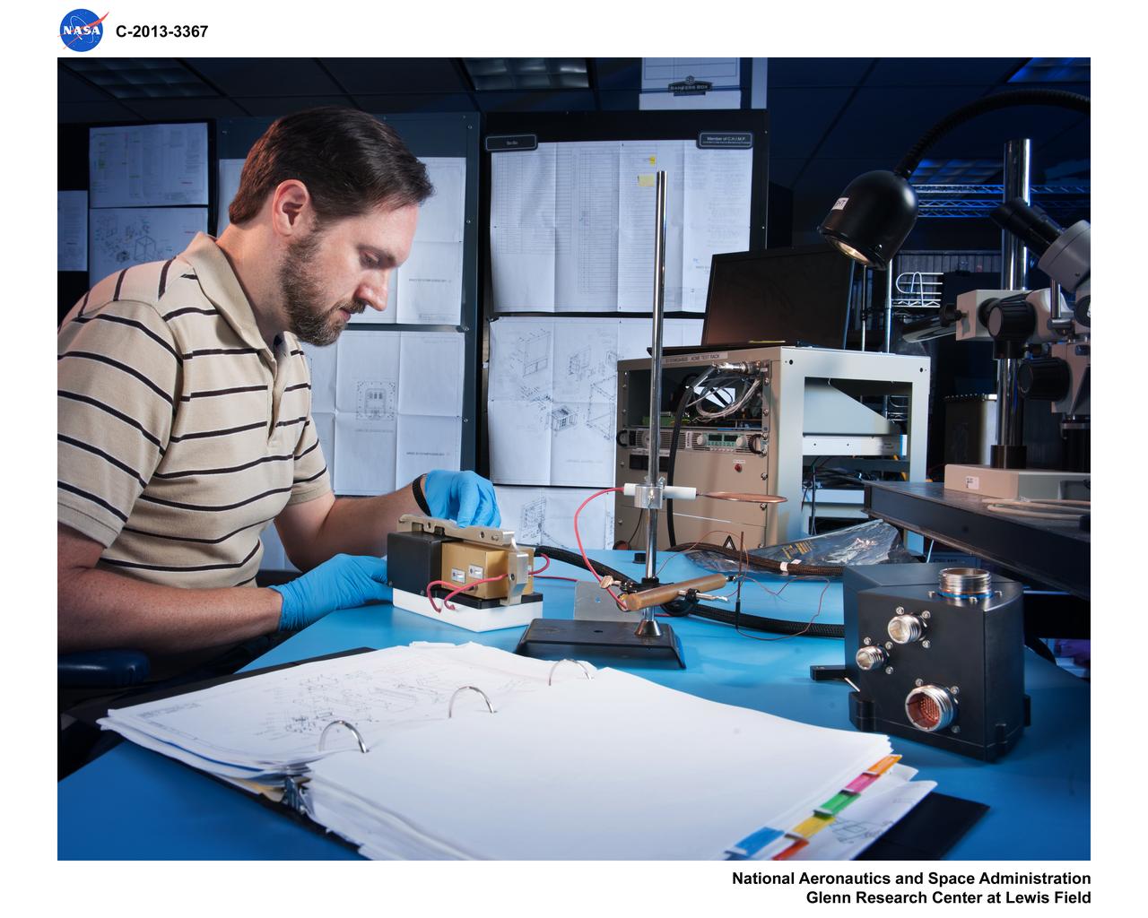
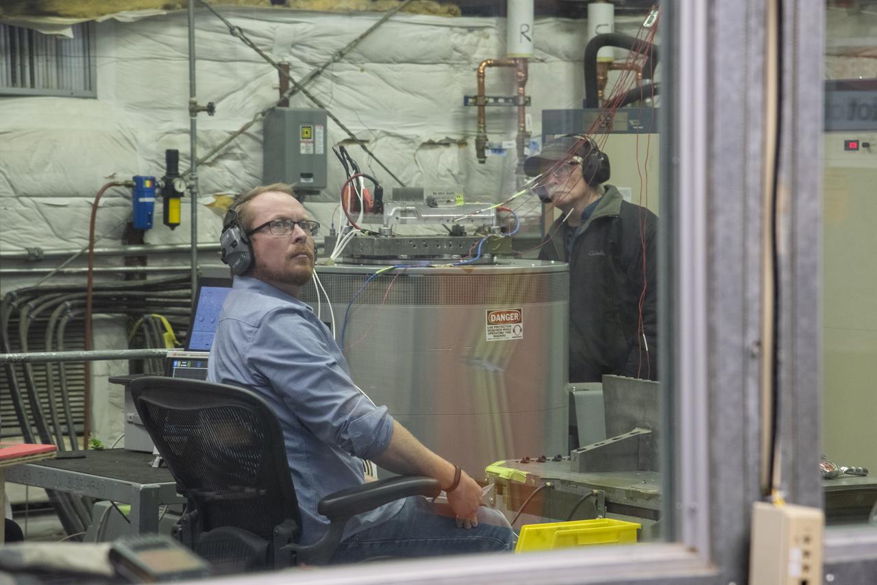
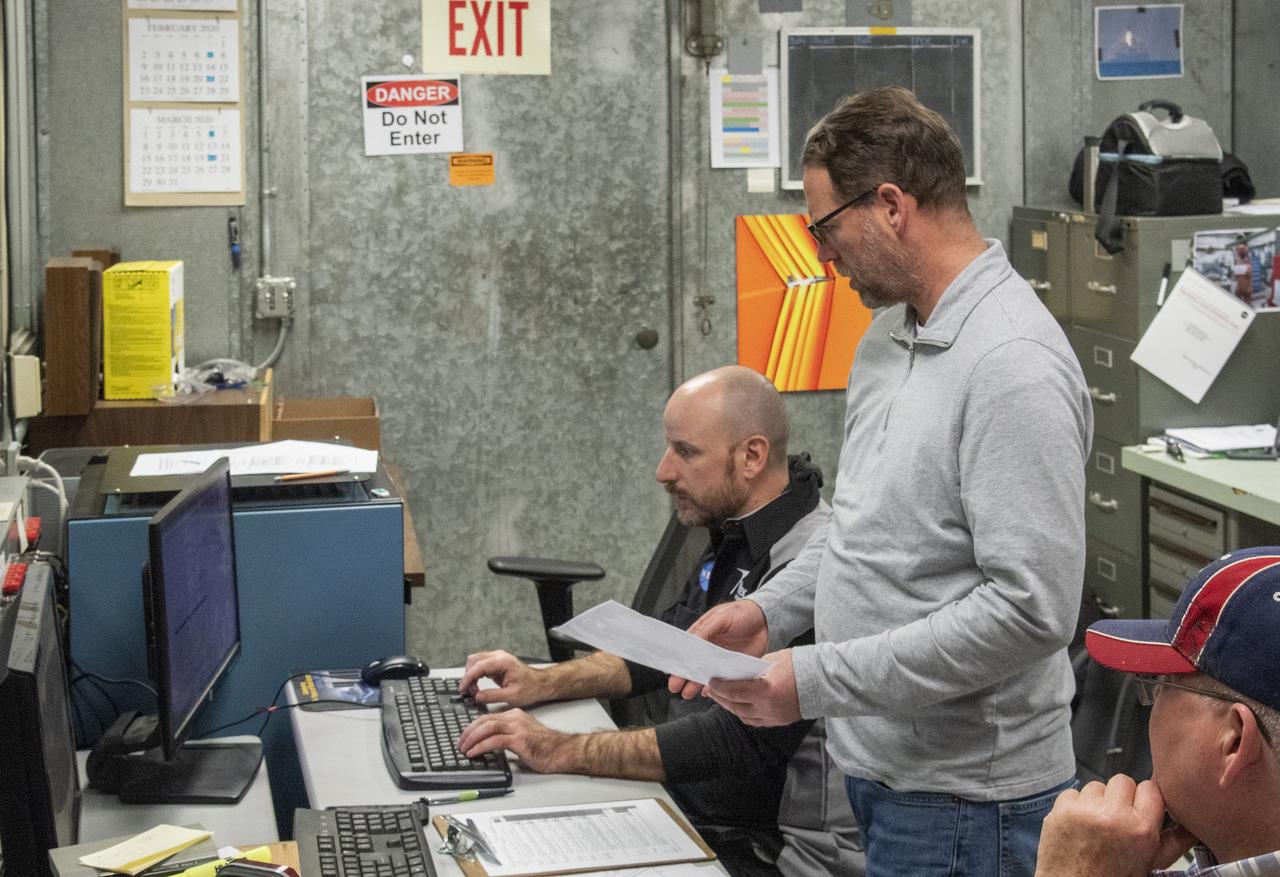
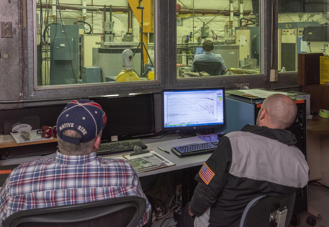
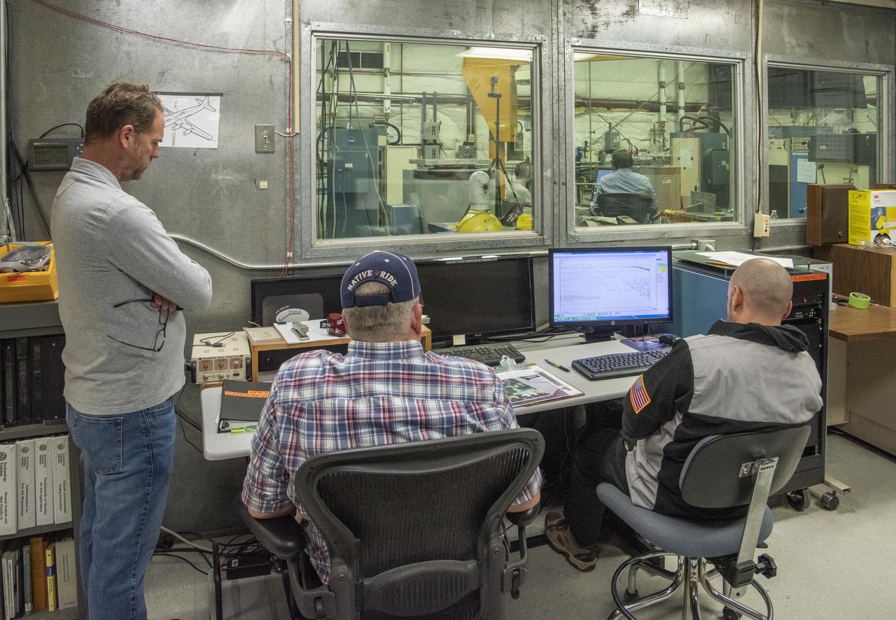
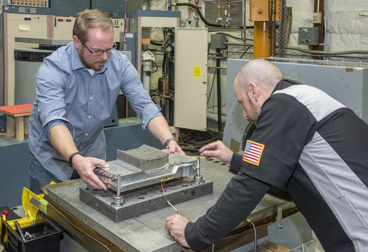
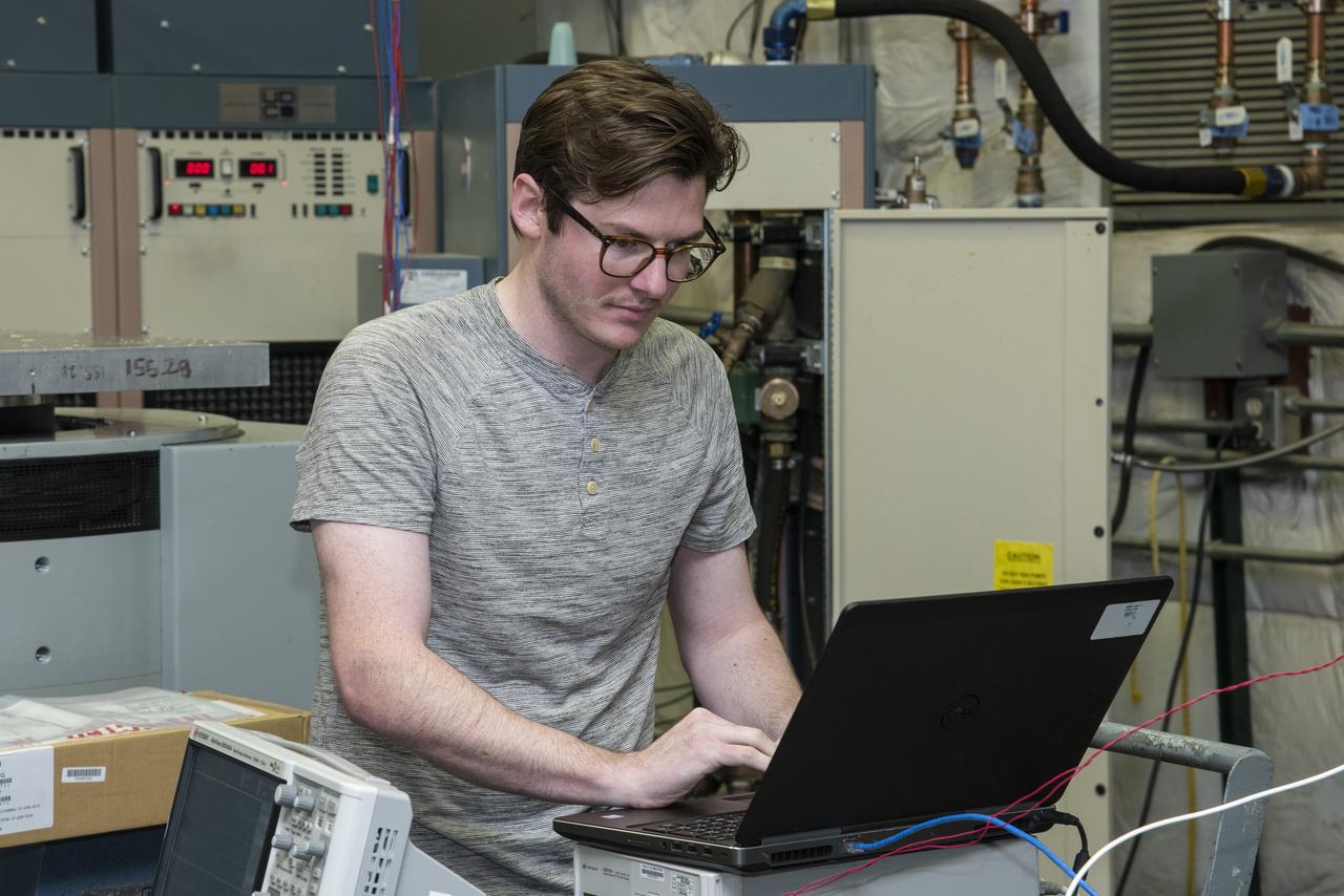
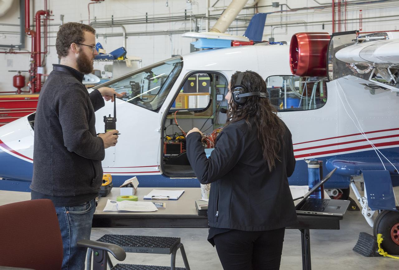
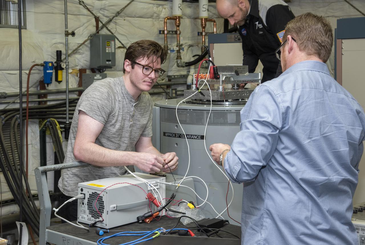
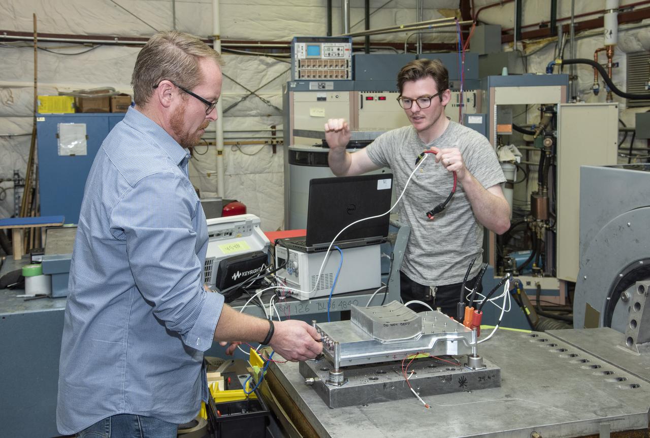
The Quiet Electric Engine V1 (QUEEN V1) experiment that was performed in the NASA GRC Acoustical Testing Laboratory (ATL). Equipment is installed in the anechoic chamber and in the adjacent control room. In response to the pervasive health and environmental problems associated with aviation noise and air pollution, NASA’s Quiet Electric Engine (QUEEN) team is working to increase the peace and quiet in the world by researching ways to make engines for large single-aisle aircraft safer, cleaner, and quieter. Posing with the experiment is aerospace engineer, Jonathan M. Goodman.
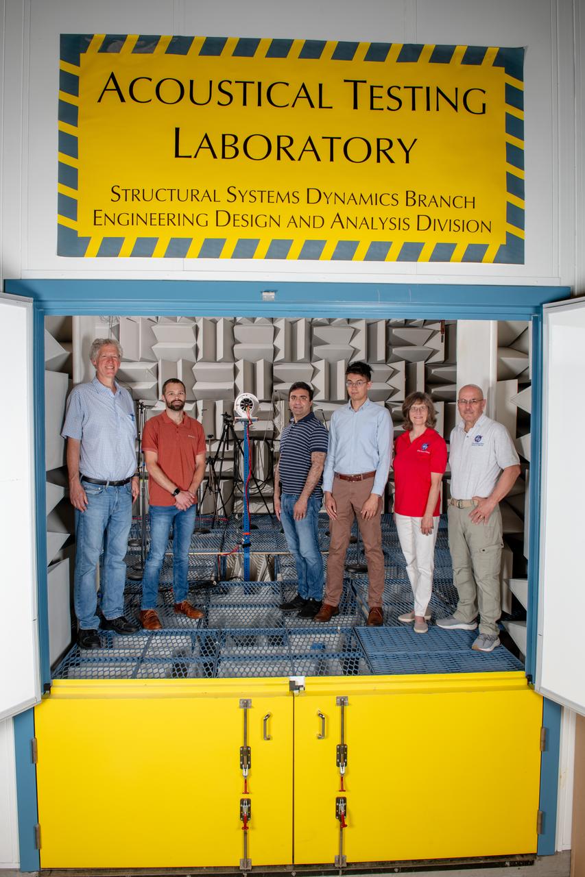
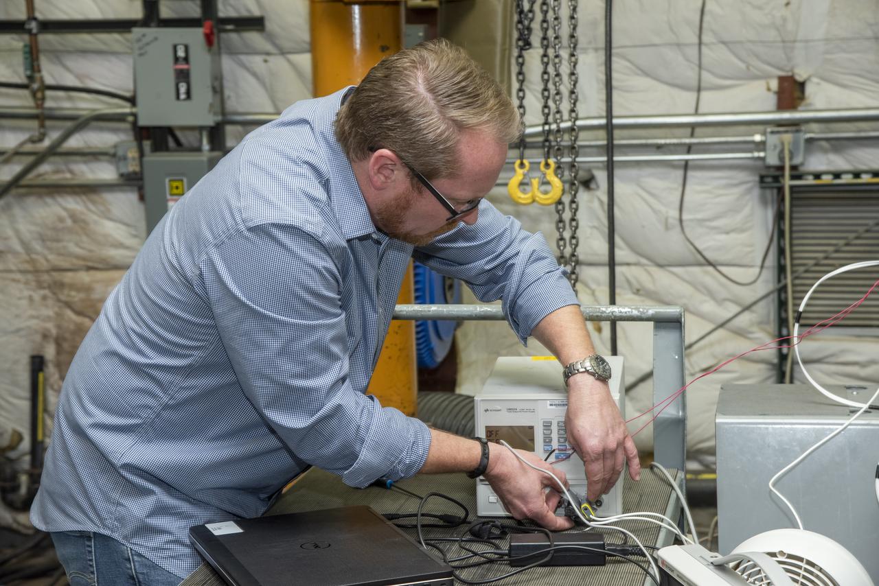
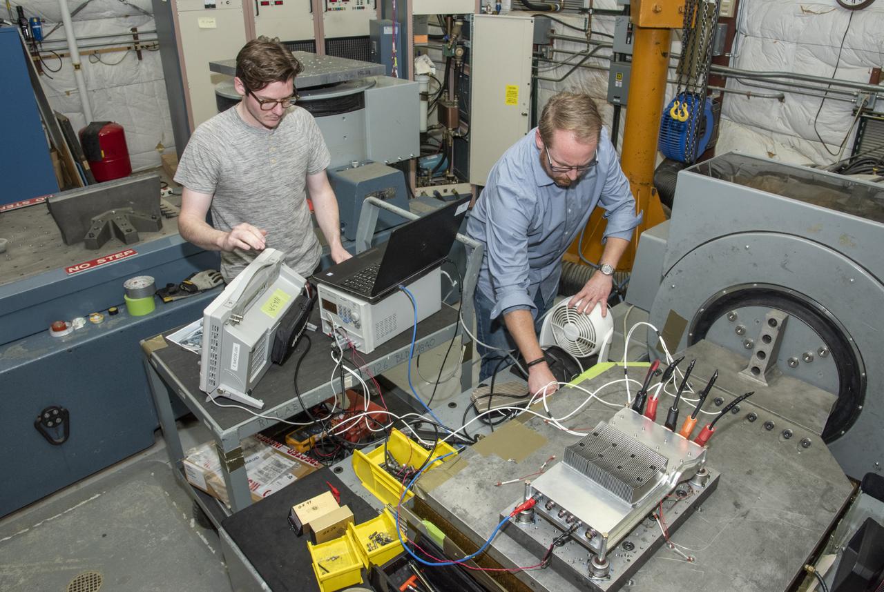
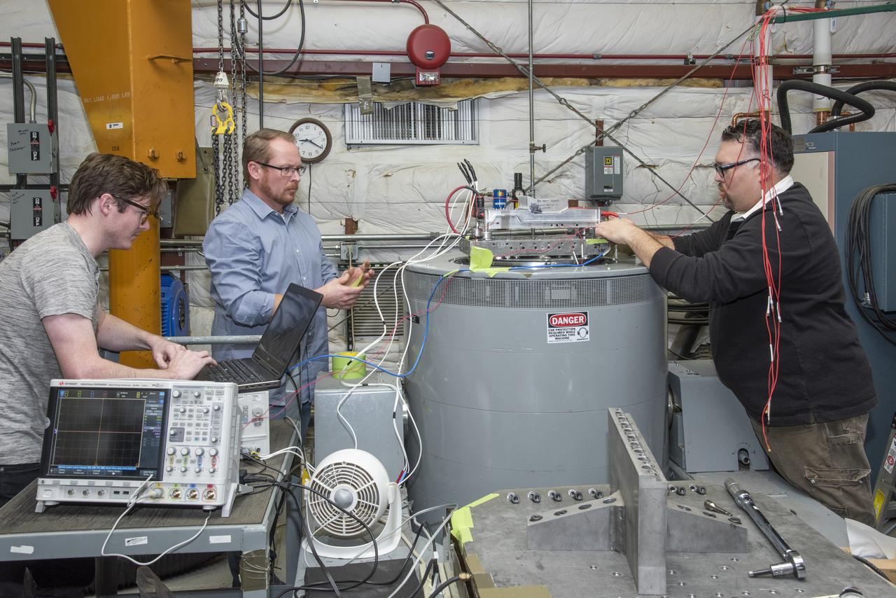
The Quiet Electric Engine V1 (QUEEN V1) experiment that was performed in the NASA GRC Acoustical Testing Laboratory (ATL). Equipment is installed in the anechoic chamber and in the adjacent control room. In response to the pervasive health and environmental problems associated with aviation noise and air pollution, NASA’s Quiet Electric Engine (QUEEN) team is working to increase the peace and quiet in the world by researching ways to make engines for large single-aisle aircraft safer, cleaner, and quieter.
The Quiet Electric Engine V1 (QUEEN V1) experiment that was performed in the NASA GRC Acoustical Testing Laboratory (ATL). Equipment is installed in the anechoic chamber and in the adjacent control room. In response to the pervasive health and environmental problems associated with aviation noise and air pollution, NASA’s Quiet Electric Engine (QUEEN) team is working to increase the peace and quiet in the world by researching ways to make engines for large single-aisle aircraft safer, cleaner, and quieter.
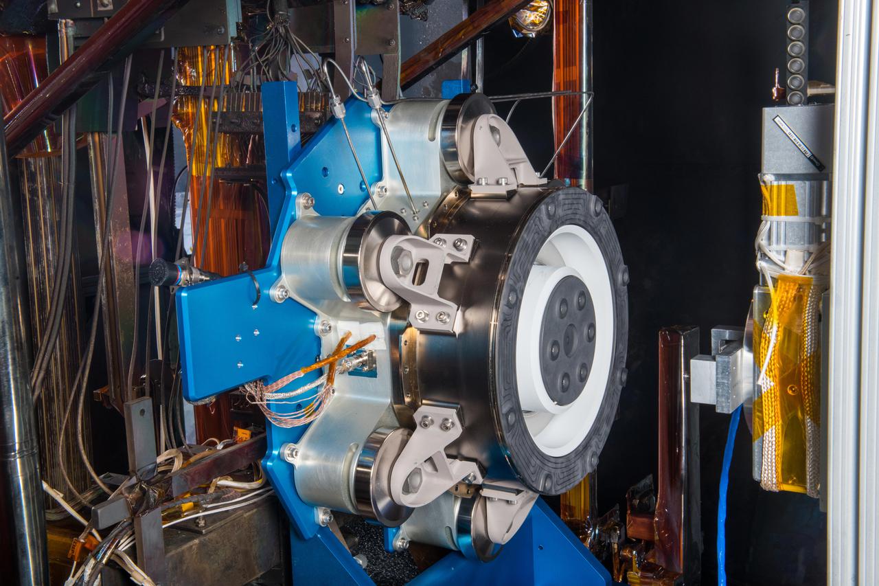
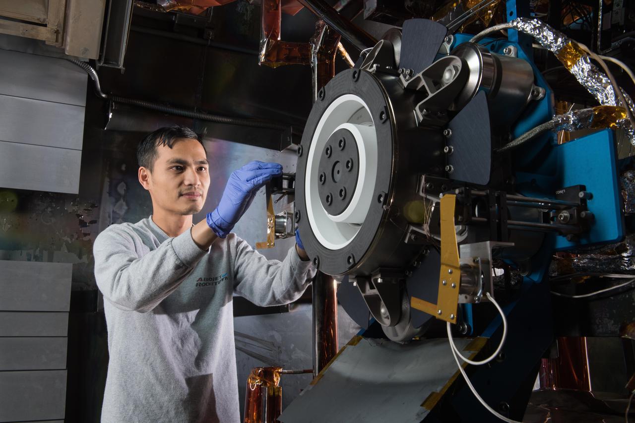
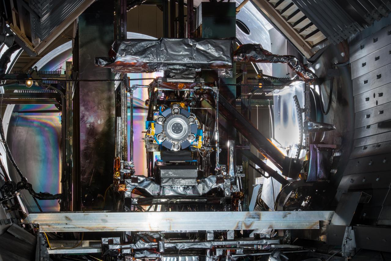
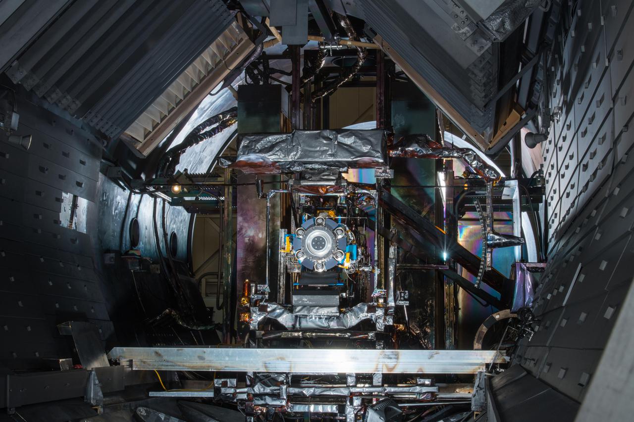
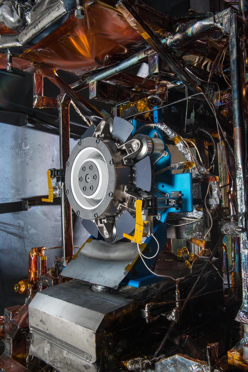
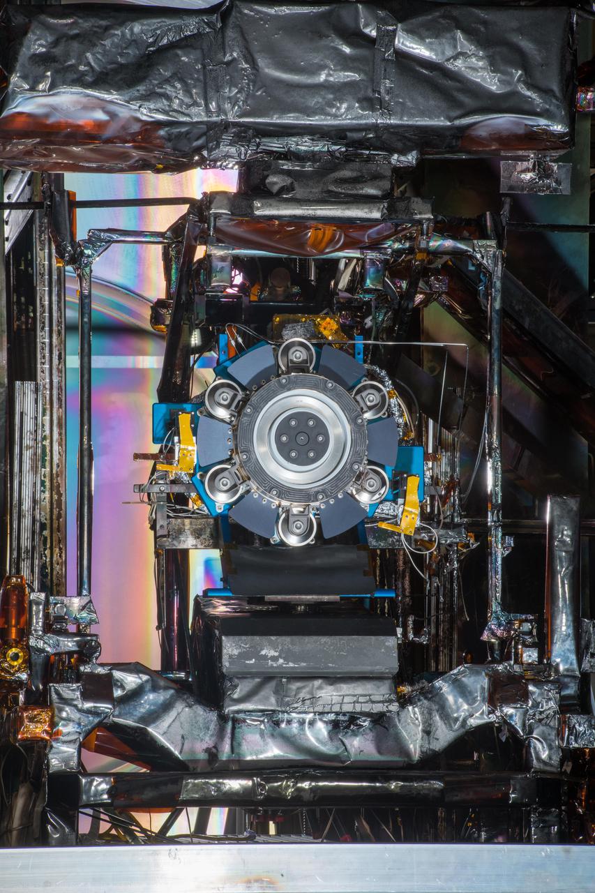
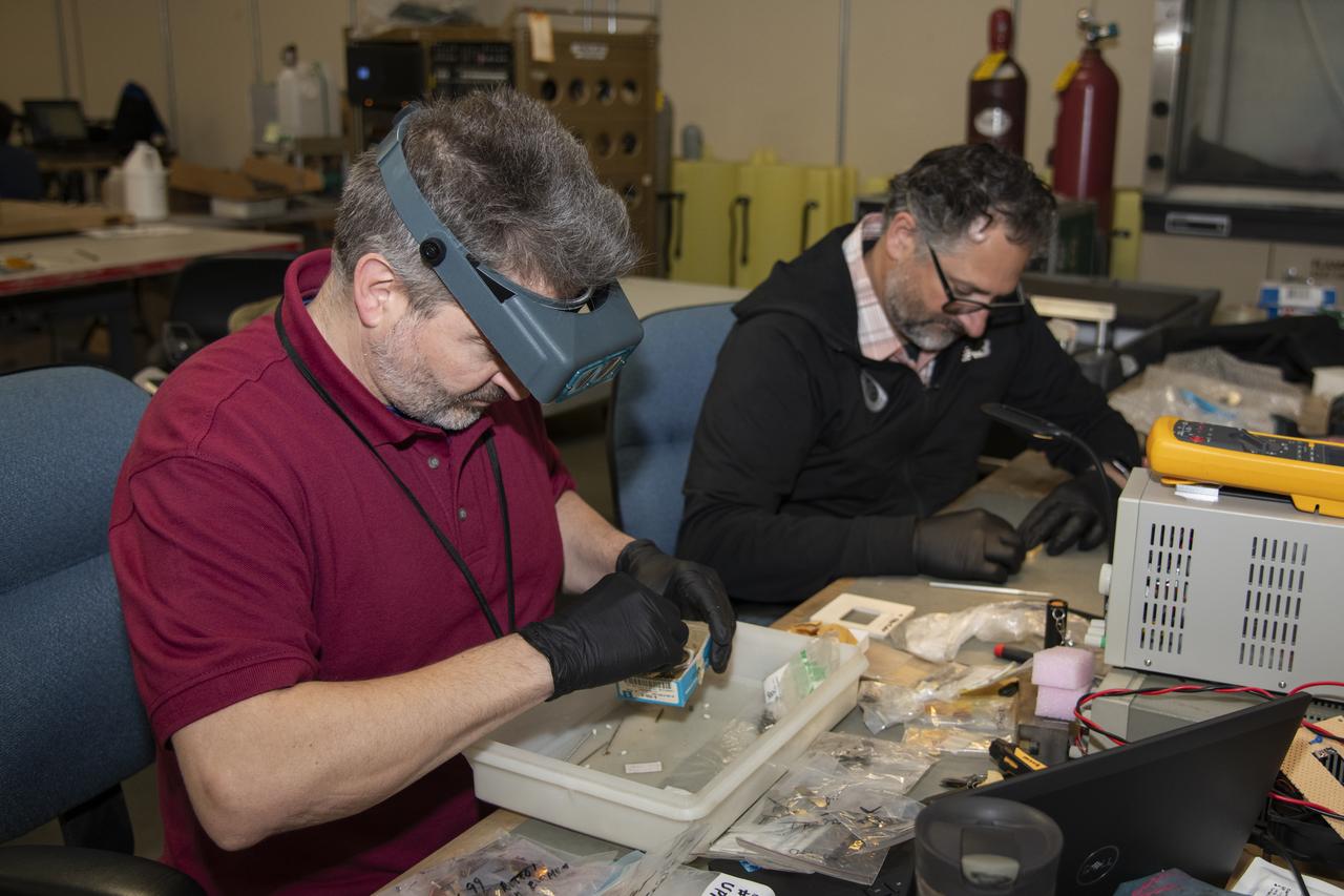
Advanced Electric Propulsion System, AEPS, Engineering Test Unit 2, ETU-2, Thruster Hardware
Advanced Electric Propulsion System, AEPS, Engineering Test Unit 2, ETU-2, Thruster Hardware
Advanced Electric Propulsion System, AEPS, Engineering Test Unit 2, ETU-2, Thruster Hardware
Advanced Electric Propulsion System, AEPS, Engineering Test Unit 2, ETU-2, Thruster Hardware
Advanced Electric Propulsion System, AEPS, Engineering Test Unit 2, ETU-2, Thruster Hardware
Advanced Electric Propulsion System, AEPS, Engineering Test Unit 2, ETU-2, Thruster Hardware

Advanced Electric Propulsion System, AEPS, Engineering Test Unit 2, ETU-2, Thruster Hardware
Advanced Electric Propulsion System, AEPS, Engineering Test Unit 2, ETU-2, Thruster Hardware
Advanced Electric Propulsion System, AEPS, Engineering Test Unit 2, ETU-2, Thruster Hardware
Advanced Electric Propulsion System, AEPS, Engineering Test Unit 2, ETU-2, Thruster Hardware
Advanced Electric Propulsion System, AEPS, Engineering Test Unit 2, ETU-2, Thruster Hardware
Advanced Electric Propulsion System, AEPS, Engineering Test Unit 2, ETU-2, Thruster Hardware

Advanced Electric Propulsion System, AEPS, Engineering Test Unit 2, ETU-2, Thruster Hardware

electrical engineer.NACA engineer Kitty Joyner, believed to be the first NACA female engineer, as well as the first women engineer to graduate from UVA.

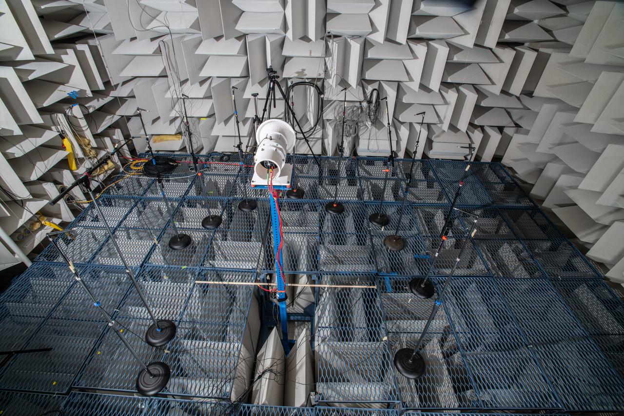
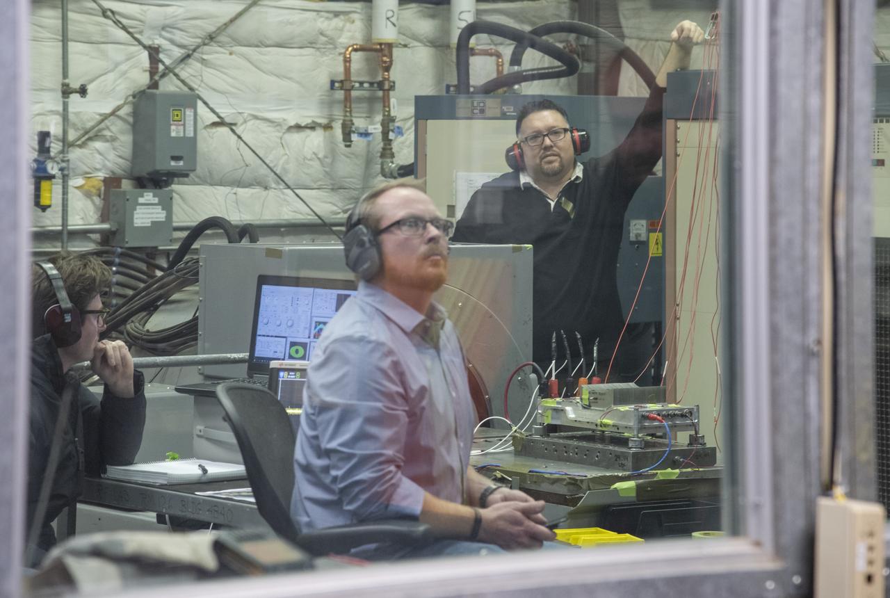
The Quiet Electric Engine V1 (QUEEN V1) experiment that was performed in the NASA GRC Acoustical Testing Laboratory (ATL). Equipment is installed in the anechoic chamber and in the adjacent control room. In response to the pervasive health and environmental problems associated with aviation noise and air pollution, NASA’s Quiet Electric Engine (QUEEN) team is working to increase the peace and quiet in the world by researching ways to make engines for large single-aisle aircraft safer, cleaner, and quieter.
The Quiet Electric Engine V1 (QUEEN V1) experiment that was performed in the NASA GRC Acoustical Testing Laboratory (ATL). Equipment is installed in the anechoic chamber and in the adjacent control room. In response to the pervasive health and environmental problems associated with aviation noise and air pollution, NASA’s Quiet Electric Engine (QUEEN) team is working to increase the peace and quiet in the world by researching ways to make engines for large single-aisle aircraft safer, cleaner, and quieter.
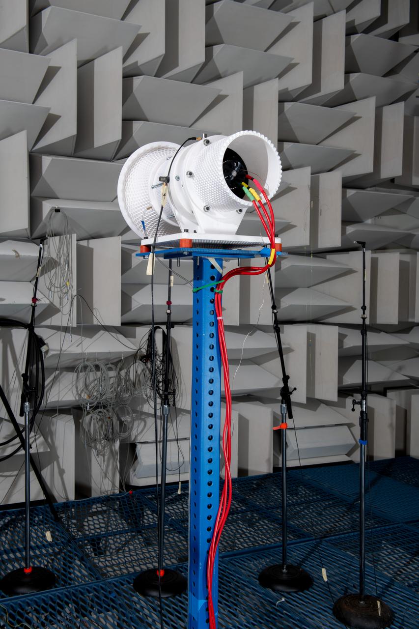
The Quiet Electric Engine V1 (QUEEN V1) experiment that was performed in the NASA GRC Acoustical Testing Laboratory (ATL). Equipment is installed in the anechoic chamber and in the adjacent control room. In response to the pervasive health and environmental problems associated with aviation noise and air pollution, NASA’s Quiet Electric Engine (QUEEN) team is working to increase the peace and quiet in the world by researching ways to make engines for large single-aisle aircraft safer, cleaner, and quieter.

New staff member Paul Margosian inspects a cluster of ion engines in the Electric Propulsion Laboratory’s 25-foot diameter vacuum tank at the National Aeronautics and Space Administration (NASA) Lewis Research Center. Lewis researchers had been studying different methods of electric rocket propulsion since the mid-1950s. Harold Kaufman created the first successful engine, the electron bombardment ion engine, in the early 1960s. These engines used electric power to create and accelerate small particles of propellant material to high exhaust velocities. Electric engines have a very small thrust, and but can operate for long periods of time. The ion engines are often clustered together to provide higher levels of thrust. The Electric Propulsion Laboratory contained two large vacuum tanks capable of simulating the space environment. The tanks were designed especially for testing ion and plasma thrusters and spacecraft. The larger 25-foot diameter tank was intended for testing electric thrusters with condensable propellants. The tank’s test compartment, seen here, was 10 feet in diameter. Margosian joined Lewis in late 1962 during a major NASA hiring phase. The Agency reorganized in 1961 and began expanding its ranks through a massive recruiting effort. Lewis personnel increased from approximately 2,700 in 1961 to over 4,800 in 1966. Margosian, who worked with Bill Kerslake in the Electromagnetic Propulsion Division’s Propulsion Systems Section, wrote eight technical reports on mercury and electron bombardment thrusters, thermoelectrostatic generators, and a high voltage insulator.
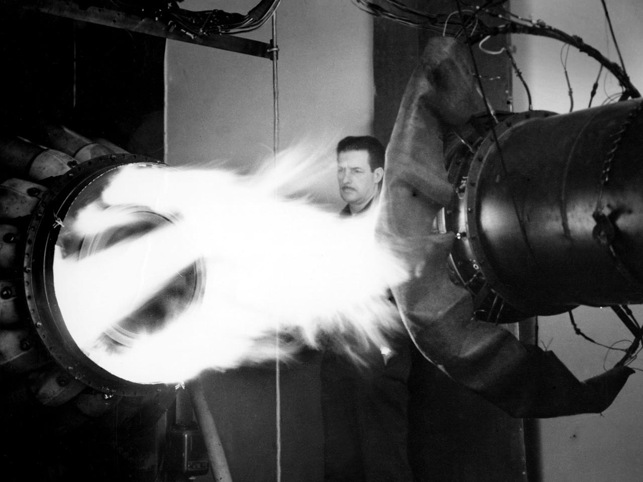
A mechanic watches the firing of a General Electric I-40 turbojet at the National Advisory Committee for Aeronautics (NACA) Lewis Flight Propulsion Laboratory. The military selected General Electric’s West Lynn facility in 1941 to secretly replicate the centrifugal turbojet engine designed by British engineer Frank Whittle. General Electric’s first attempt, the I-A, was fraught with problems. The design was improved somewhat with the subsequent I-16 engine. It was not until the engine's next reincarnation as the I-40 in 1943 that General Electric’s efforts paid off. The 4000-pound thrust I-40 was incorporated into the Lockheed Shooting Star airframe and successfully flown in June 1944. The Shooting Star became the US’s first successful jet aircraft and the first US aircraft to reach 500 miles per hour. NACA Lewis studied all of General Electric’s centrifugal turbojet models during the 1940s. In 1945 the entire Shooting Star aircraft was investigated in the Altitude Wind Tunnel. Engine compressor performance and augmentation by water injection; comparison of different fuel blends in a single combustor; and air-cooled rotors were studied. The mechanic in this photograph watches the firing of a full-scale I-40 in the Jet Propulsion Static Laboratory. The facility was quickly built in 1943 specifically in order to test the early General Electric turbojets. The I-A was secretly analyzed in the facility during the fall of 1943.

A mechanic works on a General Electric I-40 turbojet at the National Advisory Committee for Aeronautics (NACA) Lewis Flight Propulsion Laboratory. The military selected General Electric’s West Lynn facility in 1941 to secretly replicate the centrifugal turbojet engine designed by British engineer Frank Whittle. General Electric’s first attempt, the I-A, was fraught with problems. The design was improved somewhat with the subsequent I-16 engine. It was not until the engine's next reincarnation as the I-40 in 1943 that General Electric’s efforts paid off. The 4000-pound thrust I-40 was incorporated into the Lockheed Shooting Star airframe and successfully flown in June 1944. The Shooting Star became the US’s first successful jet aircraft and the first US aircraft to reach 500 miles per hour. The NACA’s Lewis Flight Propulsion Laboratory studied all of General Electric’s centrifugal turbojets both during World War II and afterwards. The entire Shooting Star aircraft was investigated in the Altitude Wind Tunnel during 1945. The researchers studied the engine compressor performance, thrust augmentation using a water injection, and compared different fuel blends in a single combustor. The mechanic in this photograph is inserting a combustion liner into one of the 14 combustor cans. The compressor, which is not yet installed in this photograph, pushed high pressure air into these combustors. There the air mixed with the fuel and was heated. The hot air was then forced through a rotating turbine that powered the engine before being expelled out the nozzle to produce thrust.
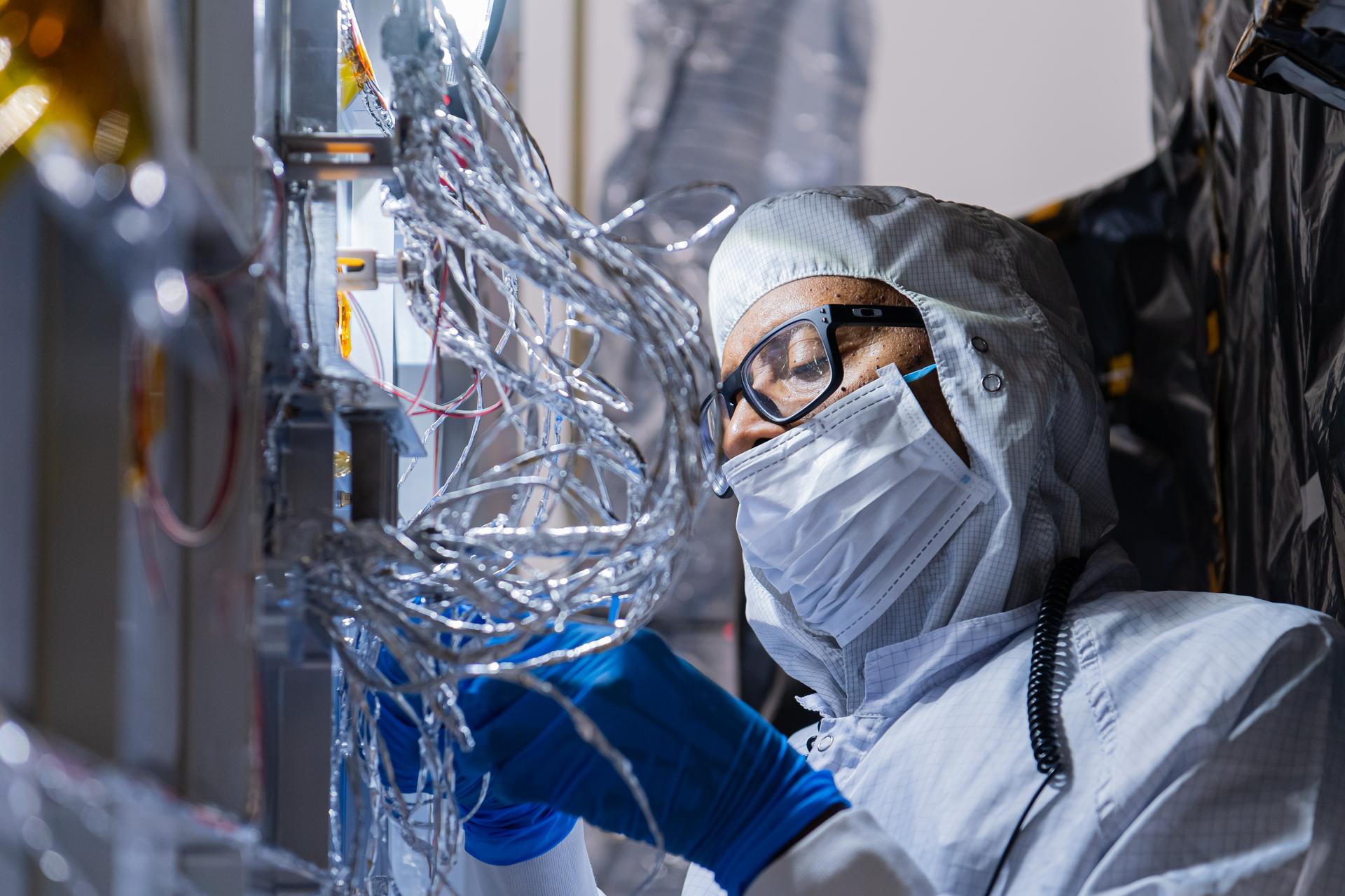
OSAM-1 Electrical Engineer Gregory Griffin tapes hardware on the underside of the OSAM-1 Servicing Payload inside cleanroom at Goddard Space Flight Center, Greenbelt Md., Aug 19, 2024. This photo has been reviewed by the Export Control Office, project Management, and Maxar release authority and is released for public view. NASA/Mike Guinto
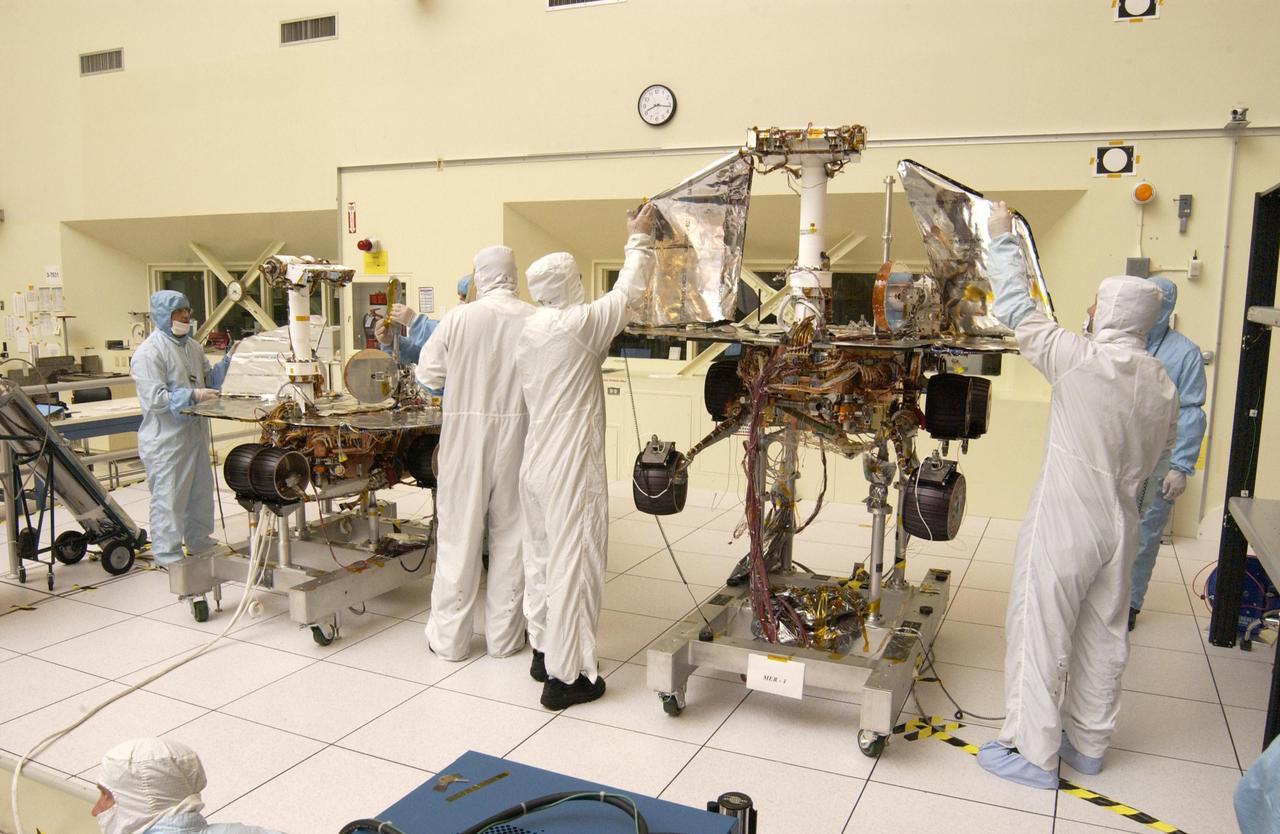
JPL engineers hand-deploying the solar arrays that provide the electrical power on NASA Mars Exploration Rover 1.
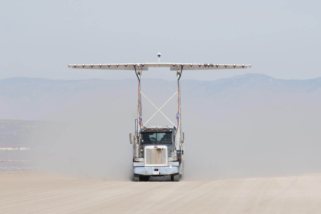
Engineers gather aerodynamic data on the integrated experimental testbed without the electric motor propellers.
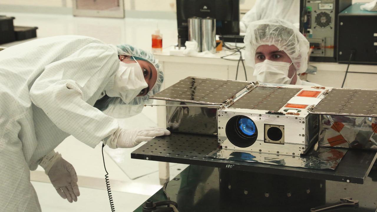
Left to right: Electrical Test Engineer Esha Murty and Integration and Test Lead Cody Colley prepare the ASTERIA spacecraft for mass-properties measurements in April 2017 prior to spacecraft delivery ahead of launch. ASTERIA was deployed from the International Space Station in November 2017. https://photojournal.jpl.nasa.gov/catalog/PIA23406
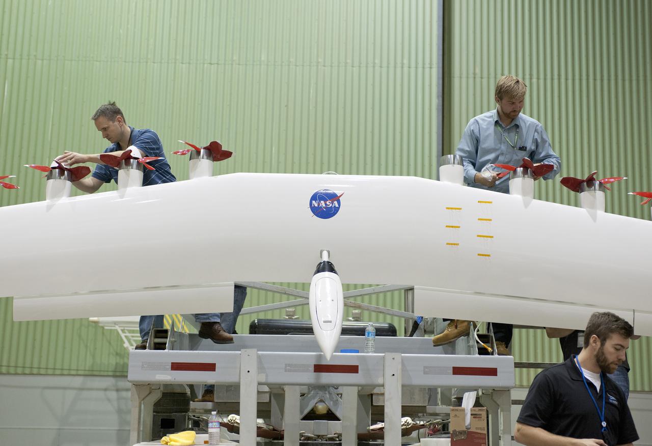
Engineers work on a wing with electric motors that is part of an integrated experimental testbed. From left are Sean Clarke, left, Kurt Papathakis at upper right and Anthony Cash in the foreground.
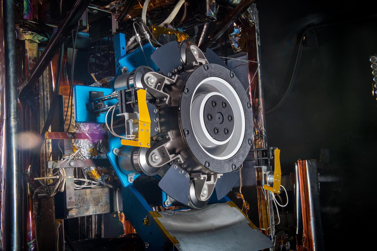
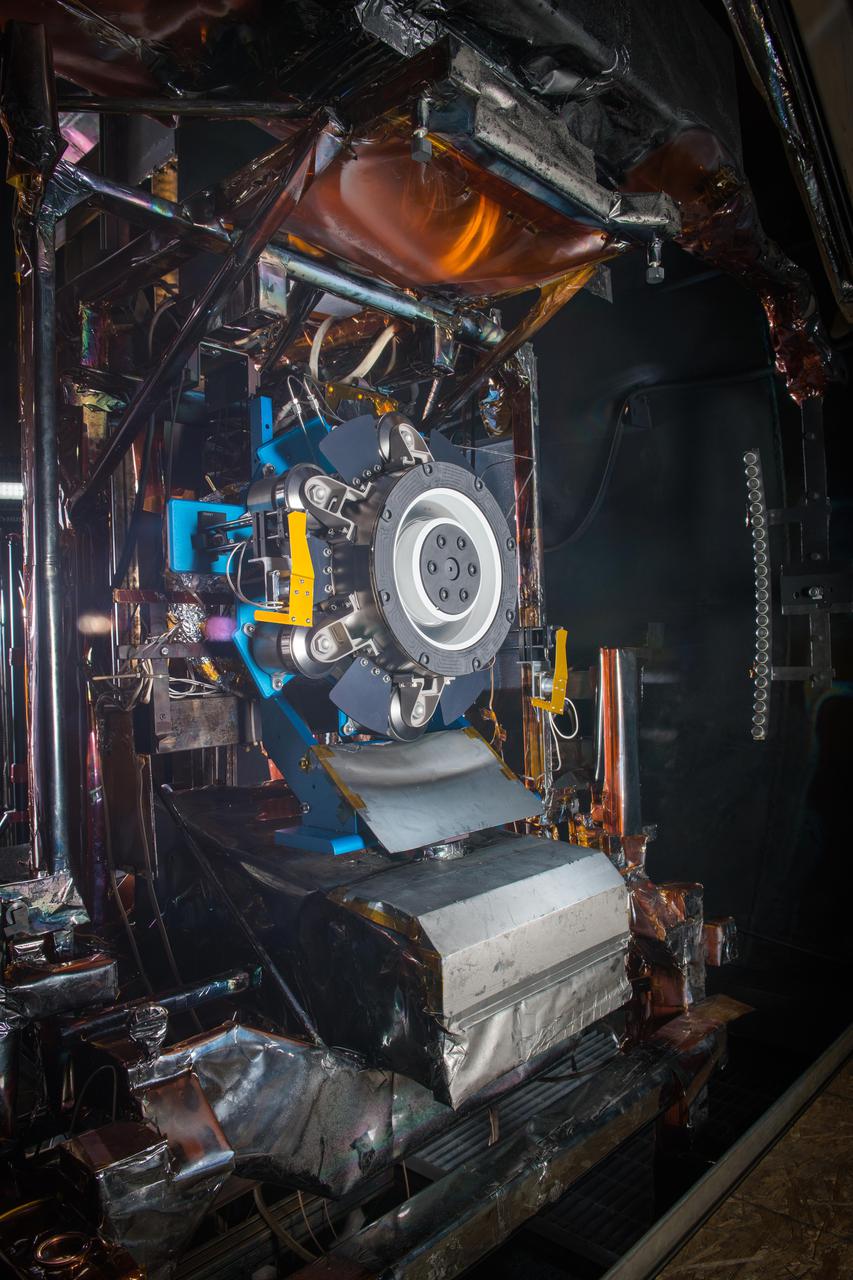
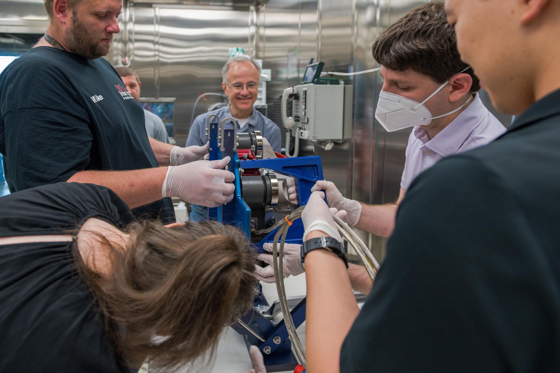
Engineers at NASA’s Glenn Research Center in Cleveland prepare the third and final Advanced Electric Propulsion System (AEPS) thruster for acceptance testing. Following successful testing, the thruster was delivered to Lanteris Space Systems in Palo Alto, California, for installation on the primary structure Gateway’s Power and Propulsion Element. Credit: NASA
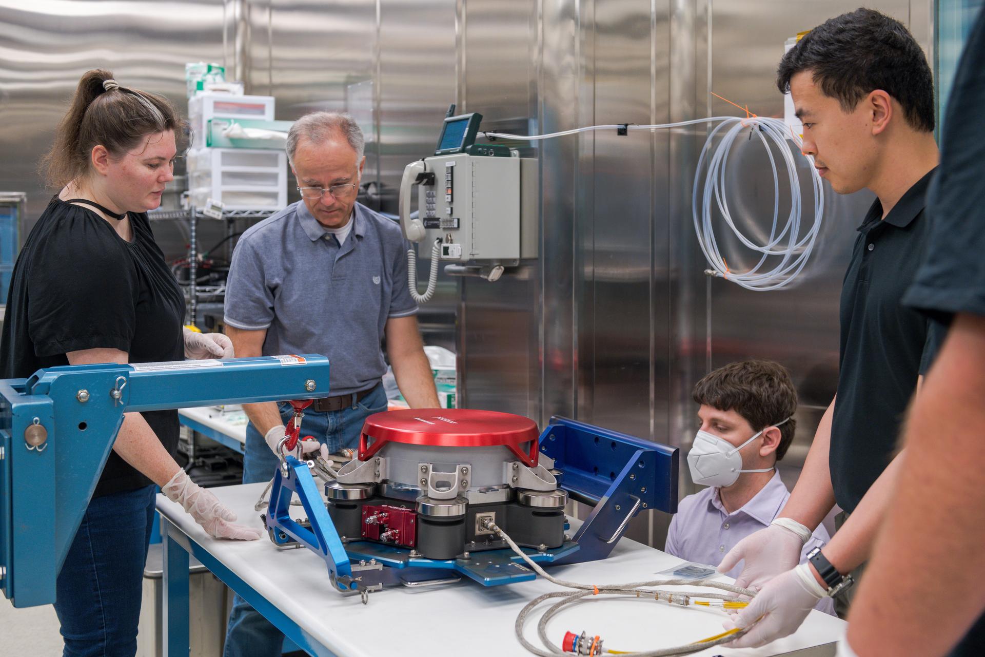
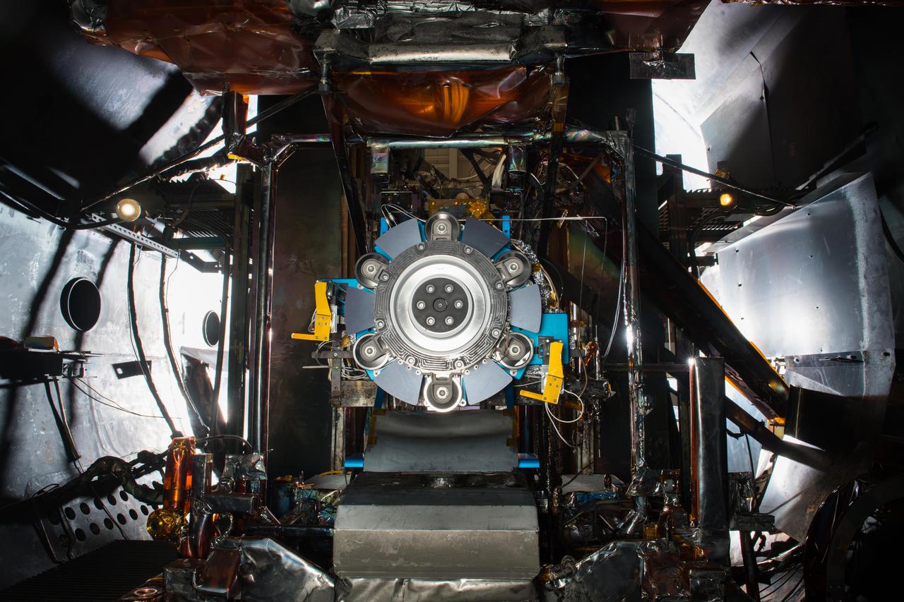
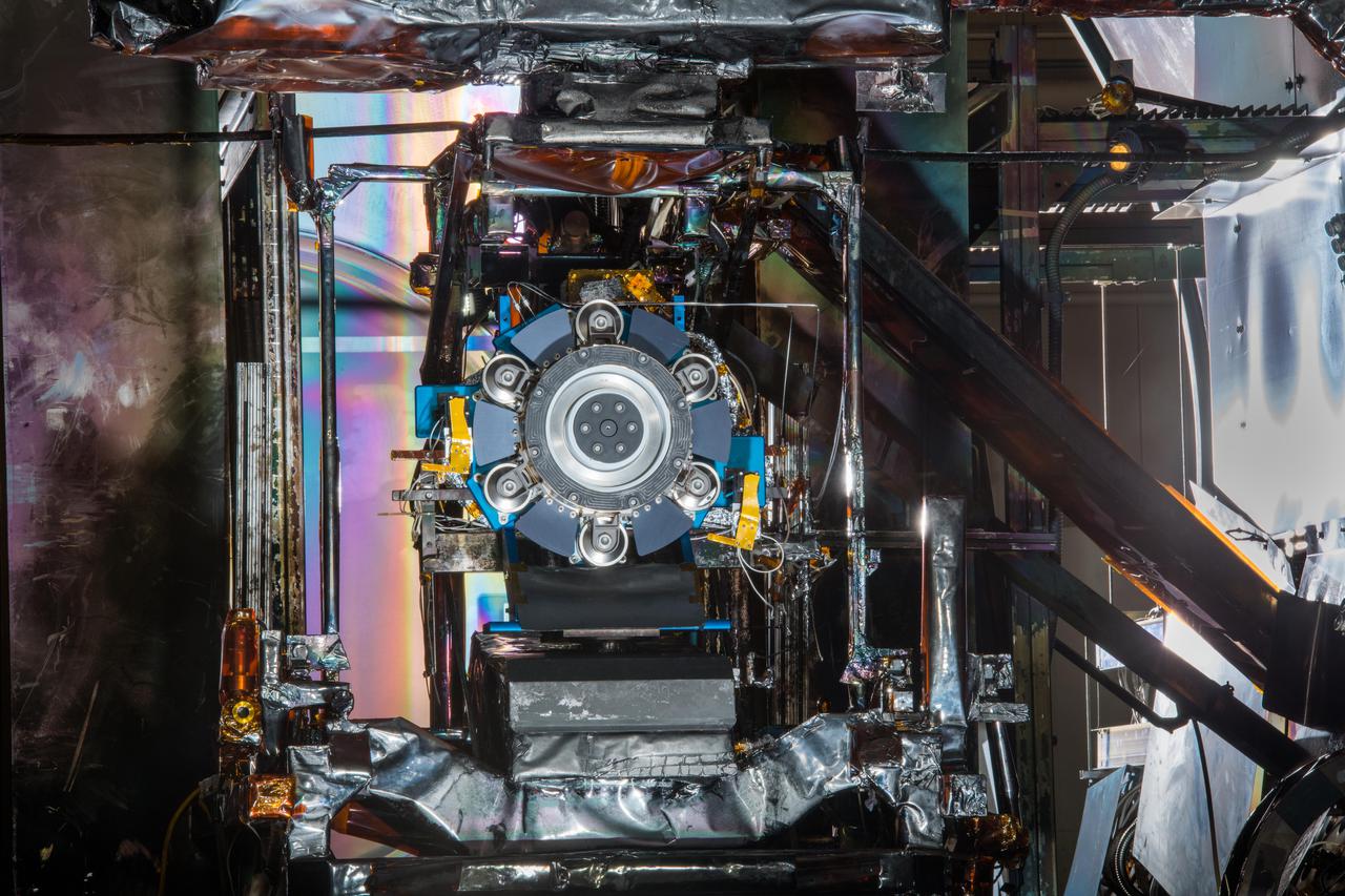
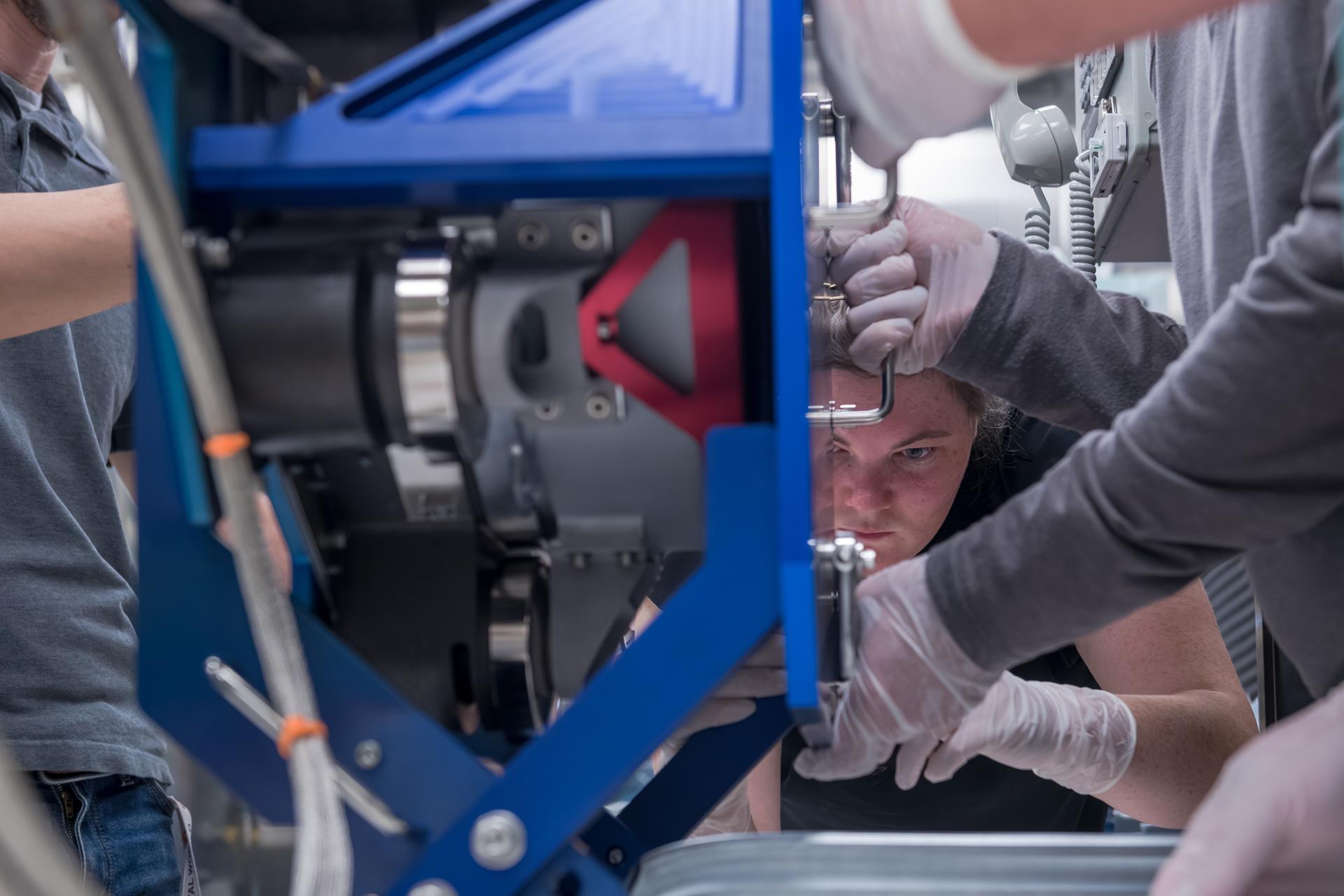
Engineers at NASA’s Glenn Research Center in Cleveland work together to position and secure the second of three Advanced Electric Propulsion System (AEPS) thrusters for acceptance testing. Following testing, the thruster was delivered to Lanteris Space Systems in Palo Alto, California, for installation on Gateway’s Power and Propulsion Element. Credit: NASA
Engineers at NASA’s Glenn Research Center in Cleveland work together to position and secure the second of three Advanced Electric Propulsion System (AEPS) thrusters for acceptance testing. Following testing, the thruster was delivered to Lanteris Space Systems in Palo Alto, California, for installation on Gateway’s Power and Propulsion Element. Credit: NASA
Environmental Portrait of an Electrical Power Systems Engineer
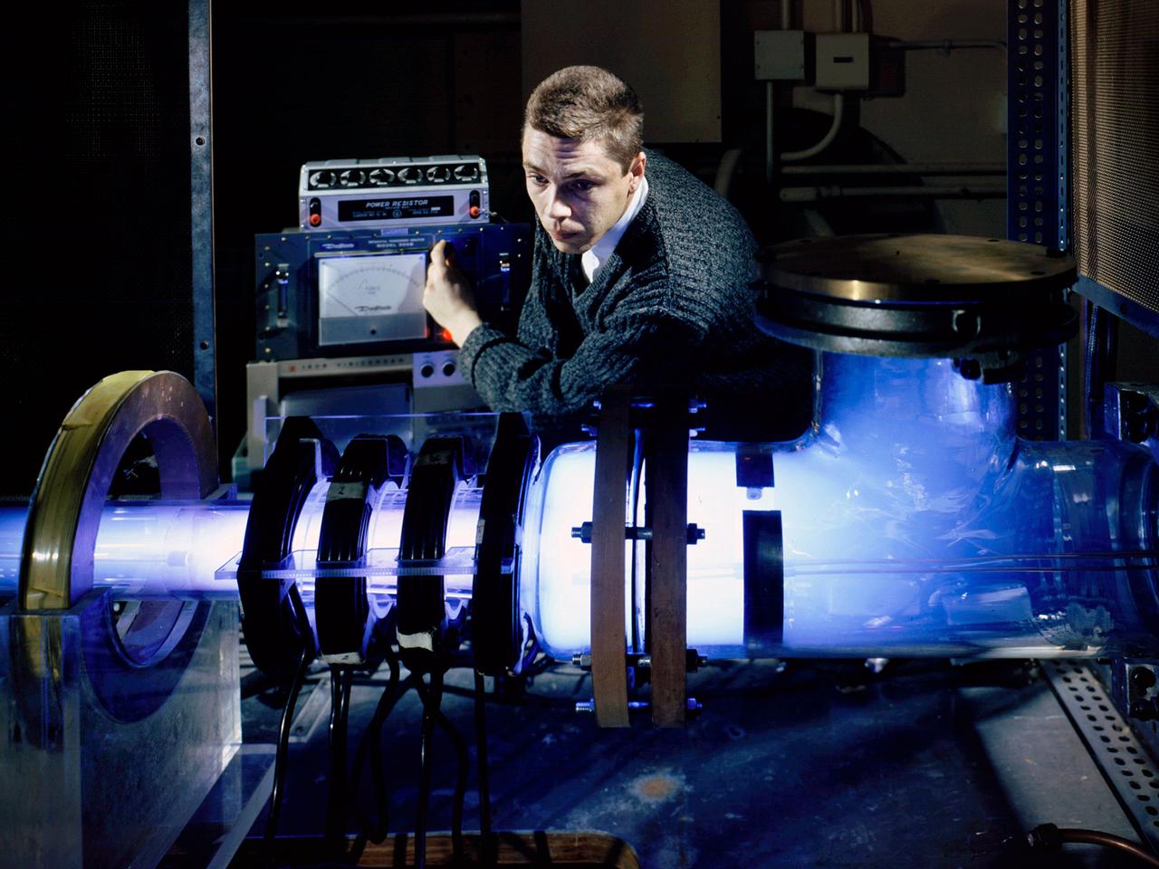
Raymond Palmer, of the Electromagnetic Propulsion Division’s Plasma Flow Section, adjusts the traveling magnetic wave plasma engine being operated in the Electric Power Conversion at the National Aeronautics and Space Administration (NASA) Lewis Research Center. During the 1960s Lewis researchers were exploring several different methods of creating electric propulsion systems, including the traveling magnetic wave plasma engine. The device operated similarly to alternating-current motors, except that a gas, not a solid, was used to conduct the electricity. A magnetic wave induced a current as it passed through the plasma. The current and magnetic field pushed the plasma in one direction. Palmer and colleague Robert Jones explored a variety of engine configurations in the Electric Propulsion Research Building. The engine is seen here mounted externally on the facility’s 5-foot diameter and 16-foot long vacuum tank. The four magnetic coils are seen on the left end of the engine. The researchers conducted two-minute test runs with varying configurations and used of both argon and xenon as the propellant. The Electric Propulsion Research Building was built in 1942 as the Engine Propeller Research Building, often called the Prop House. It contained four test cells to study large reciprocating engines with their propellers. After World War II, the facility was modified to study turbojet engines. By the 1960s, the facility was modified again for electric propulsion research and given its current name.
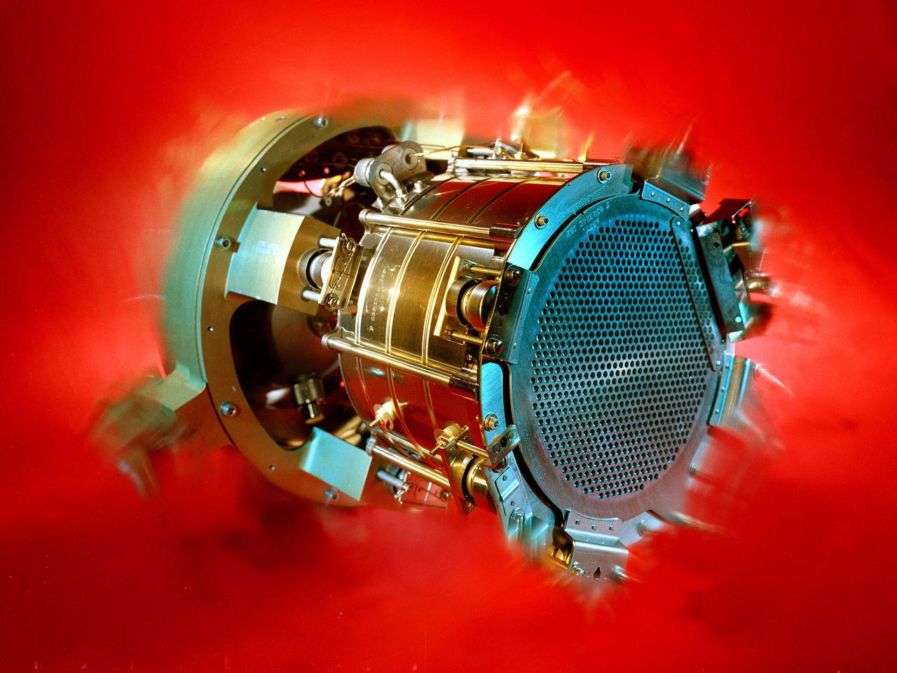
Researchers at the Lewis Research Center had been studying different methods of electric rocket propulsion since the mid-1950s. Harold Kaufman created the first successful engine, the electron bombardment ion engine, in the early 1960s. Over the ensuing decades Lewis researchers continued to advance the original ion thruster concept. A Space Electric Rocket Test (SERT) spacecraft was launched in June 1964 to test Kaufman’s engine in space. SERT I had one cesium engine and one mercury engine. The suborbital flight was only 50 minutes in duration but proved that the ion engine could operate in space. This was followed in 1966 by the even more successful SERT II, which operated on and off for over ten years. Lewis continued studying increasingly more powerful ion thrusters. These electric engines created and accelerated small particles of propellant material to high exhaust velocities. Electric engines have a very small amount of thrust and are therefore not capable of lifting a spaceship from the surface of the Earth. Once lofted into orbit, however, electric engines are can produce small, continuous streams of thrust for several years.
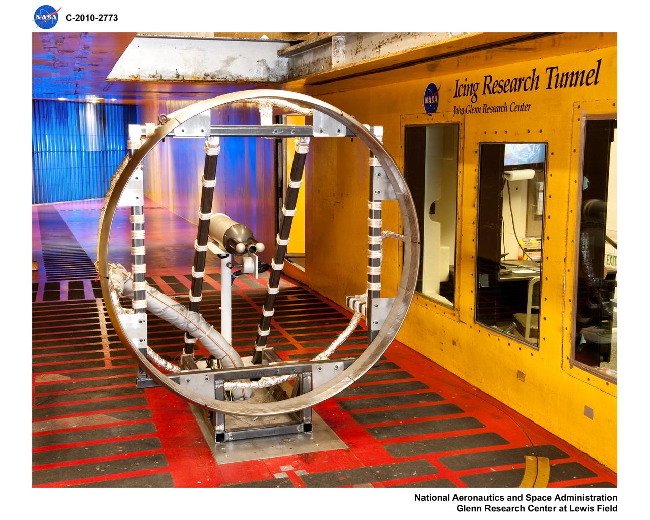
General Electric Aviation - Engine Splitter Booster Model in the Icing Research Tunnel
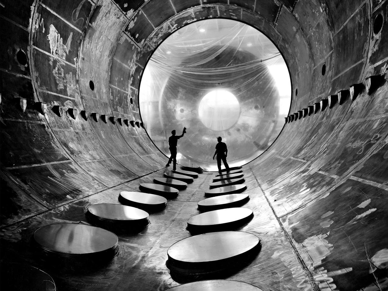
Interior of the 20-foot diameter vacuum tank at the NASA Lewis Research Center’s Electric Propulsion Laboratory. Lewis researchers had been studying different electric rocket propulsion methods since the mid-1950s. Harold Kaufman created the first successful ion engine, the electron bombardment ion engine, in the early 1960s. These engines used electric power to create and accelerate small particles of propellant material to high exhaust velocities. Electric engines have a very small thrust, but can operate for long periods of time. The ion engines are often clustered together to provide higher levels of thrust. The Electric Propulsion Laboratory, which began operation in 1961, contained two large vacuum tanks capable of simulating a space environment. The tanks were designed especially for testing ion and plasma thrusters and spacecraft. The larger 25-foot diameter tank included a 10-foot diameter test compartment to test electric thrusters with condensable propellants. The portals along the chamber floor lead to the massive exhauster equipment that pumped out the air to simulate the low pressures found in space.
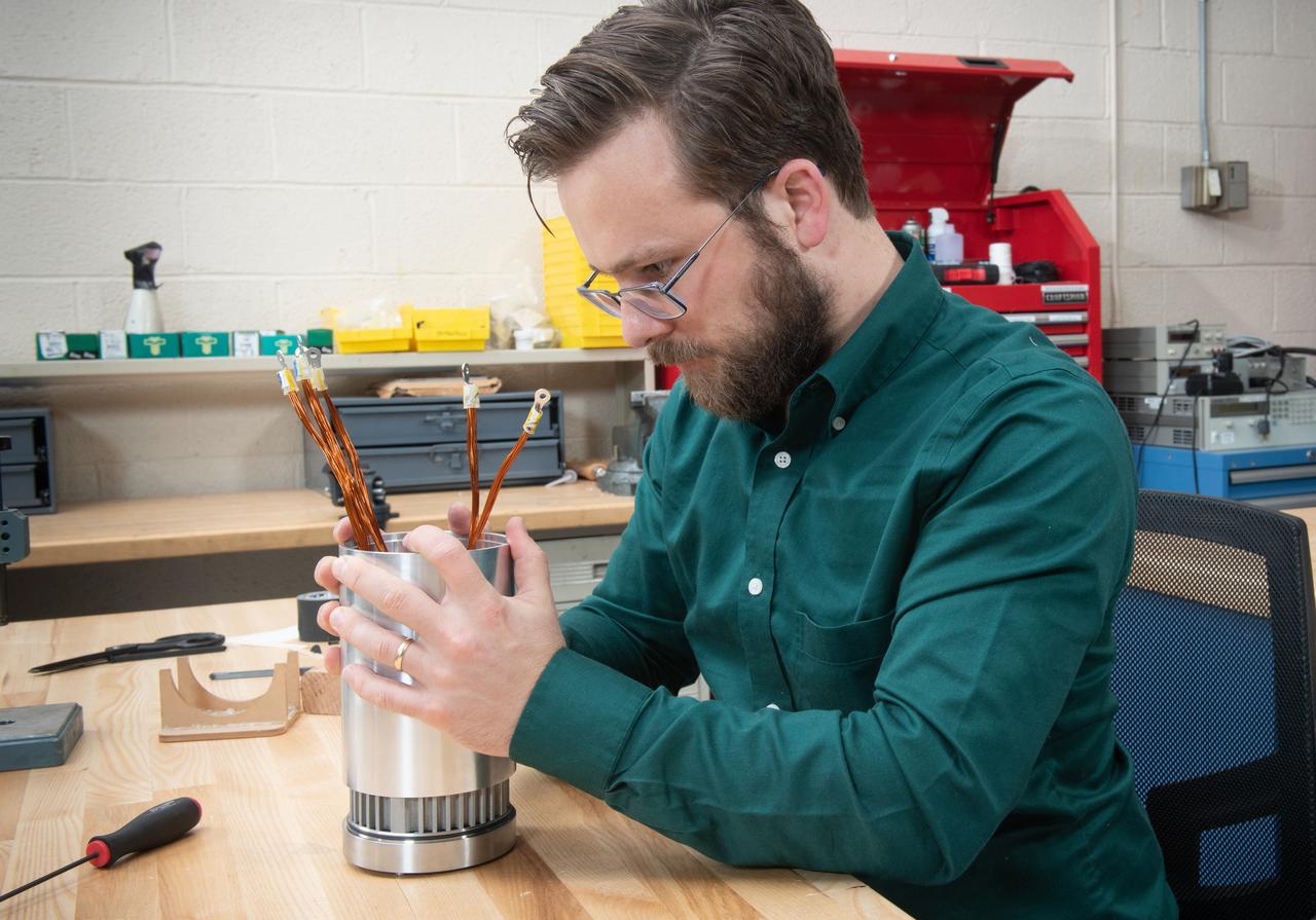
Assembly of a 20kW Electric Kokomotor for the SUbsonic Single Aft eNgine, SUSAN, 25% Flight Research Vehicle
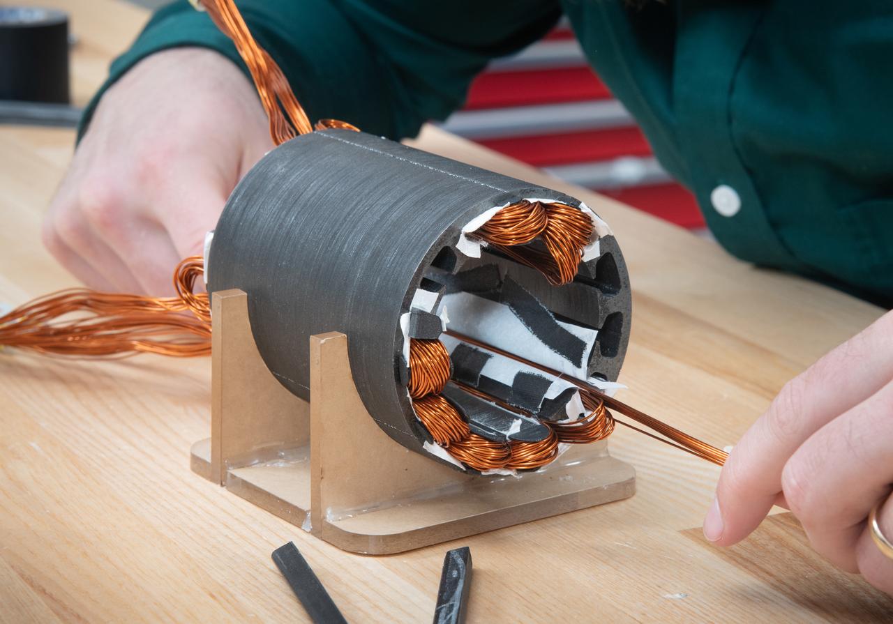
Assembly of a 20kW Electric Kokomotor for the SUbsonic Single Aft eNgine, SUSAN, 25% Flight Research Vehicle
Assembly of a 20kW Electric Kokomotor for the SUbsonic Single Aft eNgine, SUSAN, 25% Flight Research Vehicle
Assembly of a 20kW Electric Kokomotor for the SUbsonic Single Aft eNgine, SUSAN, 25% Flight Research Vehicle
Second Generation Agile Engineering Prototype of Electric Sail 6U CubeSat Testbed Article
First Generation Agile Engineering Prototype of Electric Sail 6U CubeSat Testbed Article
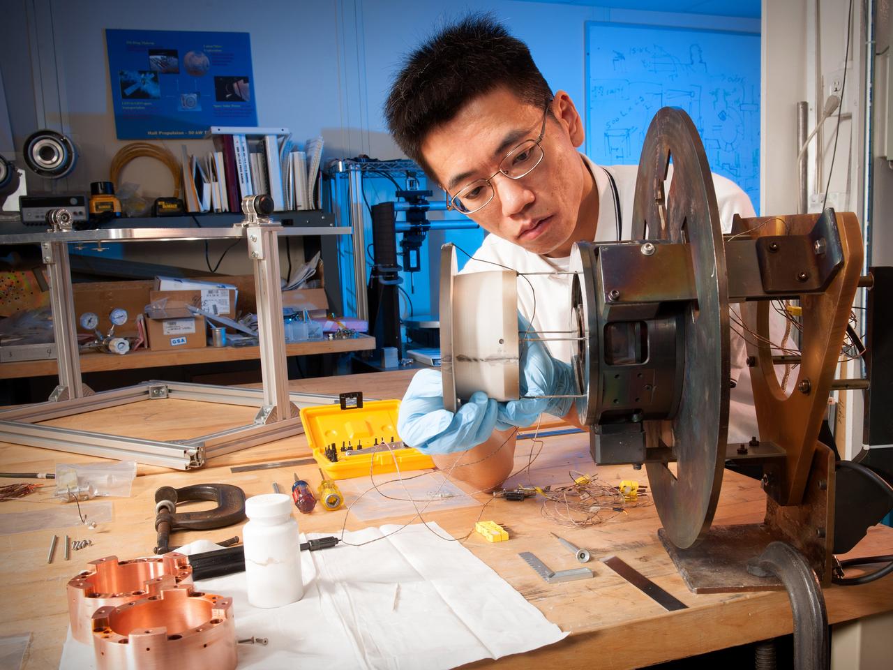
Environmental Portrait of Research Engineer Wensheng Huang working on a Hall thruster in the Electric Propulsion Laboratory at NASA Glenn Research Center.
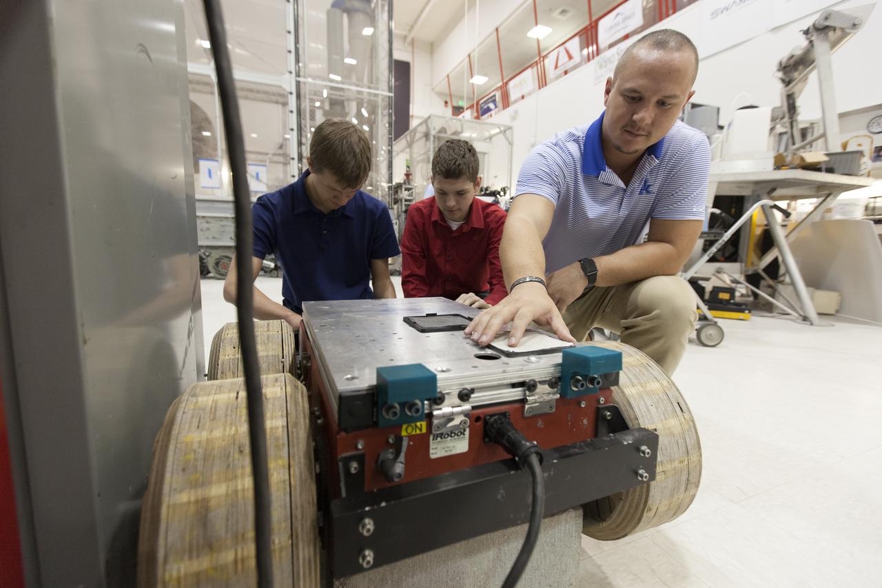
In the Swamp Works laboratory at NASA's Kennedy Space Center in Florida, student interns, from the left, Jeremiah House, Thomas Muller and Austin Langdon are joining agency scientists, contributing in the area of Exploration Research and Technology. House is studying computer/electrical engineering at John Brown University in Siloam Springs, Arkansas. Muller is pursuing a degree in computer engineering and control systems and Florida Tech. Langdon is an electrical engineering major at the University of Kentucky. The agency attracts its future workforce through the NASA Internship, Fellowships and Scholarships, or NIFS, Program.
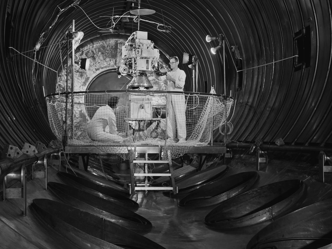
Technicians prepare the Space Electric Research Test (SERT-I) payload for a test in Tank Number 5 of the Electric Propulsion Laboratory at the National Aeronautics and Space Administration (NASA) Lewis Research Center. Lewis researchers had been studying different methods of electric rocket propulsion since the mid-1950s. Harold Kaufman created the first successful engine, the electron bombardment ion engine, in the early 1960s. These electric engines created and accelerated small particles of propellant material to high exhaust velocities. Electric engines have a very small amount of thrust, but once lofted into orbit by workhorse chemical rockets, they are capable of small, continuous thrust for periods up to several years. The electron bombardment thruster operated at a 90-percent efficiency during testing in the Electric Propulsion Laboratory. The package was rapidly rotated in a vacuum to simulate its behavior in space. The SERT-I mission, launched from Wallops Island, Virginia, was the first flight test of Kaufman’s ion engine. SERT-I had one cesium engine and one mercury engine. The suborbital flight was only 50 minutes in duration but proved that the ion engine could operate in space. The Electric Propulsion Laboratory included two large space simulation chambers, one of which is seen here. Each uses twenty 2.6-foot diameter diffusion pumps, blowers, and roughing pumps to remove the air inside the tank to create the thin atmosphere. A helium refrigeration system simulates the cold temperatures of space.

Here is an image of the X-59’s 13-foot General Electric F414 engine as the team prepares for a fit check. Making sure components, like the aircraft’s hydraulic lines, which help control functions like brakes or landing gear, and wiring of the engine, fit properly is essential to the aircraft’s safety. Once complete, the X-59 aircraft will demonstrate the ability to fly supersonic while reducing the loud sonic boom to a quiet sonic thump and help enable commercial supersonic air travel over land.
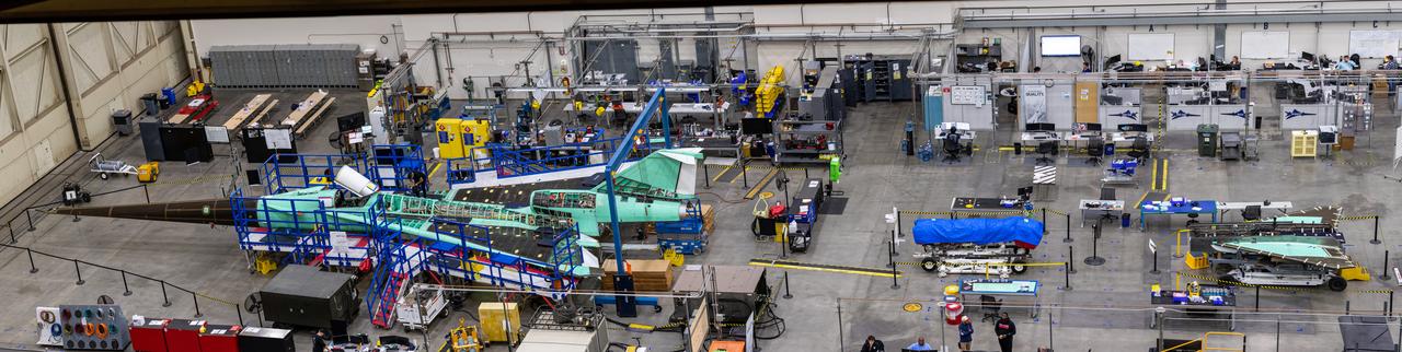
Here is an overhead view of the X-59 aircraft (left) prior to the installation of the General Electric F414 engine (center, located under the blue cover). After the engine is installed, the lower empennage (right), the last remaining major aircraft component, will be installed in preparation for integrated system checkouts. The X-59 is the centerpiece of the Quesst mission which plans to help enable commercial supersonic air travel over land.
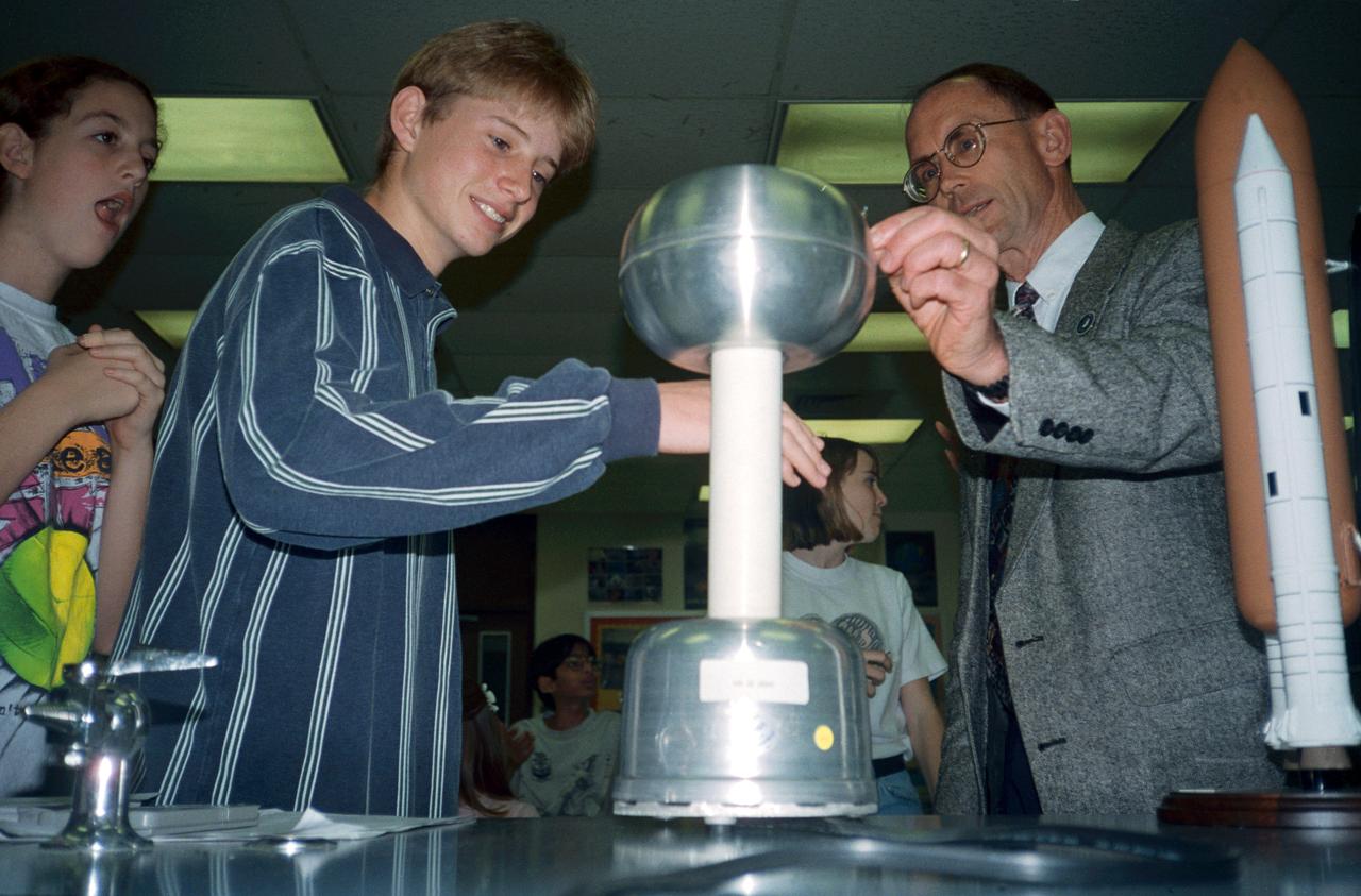
Johnson Space Center (JSC) engineers visit Houston area schools for National Engineers Week. Students examine a machine that generates static electricity (4296-7). Students examine model rockets (4298).
The Harvard Halogen Instrument (HAL) is prepared for integration on NASA's ER-2 by electrical engineer Marco Rivero and mechanical engineer Michael Greenberg for the Dynamics and Chemistry of the Summer Stratosphere, or DCOTSS, 2022 campaign.
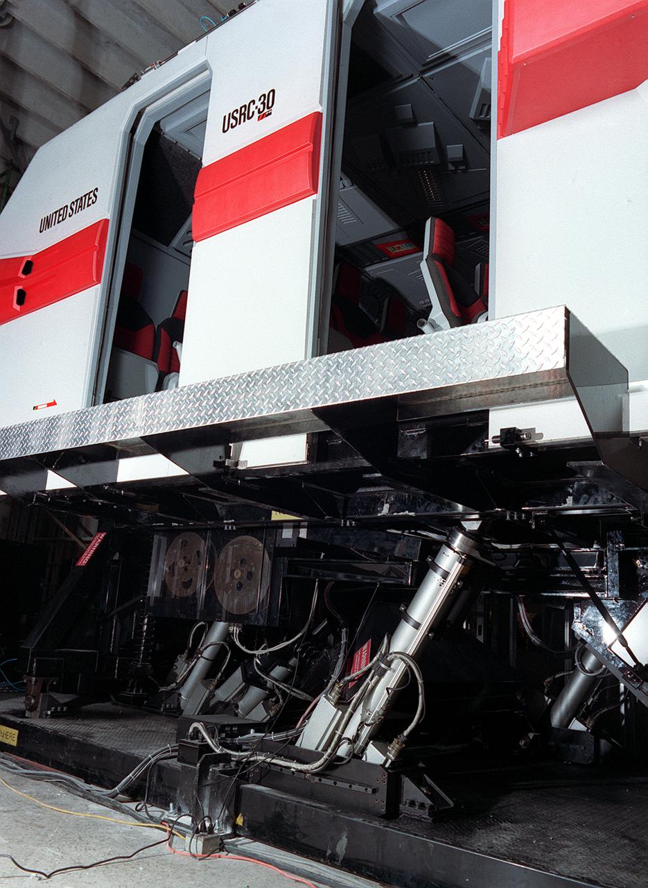
The development of the electric space actuator represents an unusual case of space technology transfer wherein the product was commercialized before it was used for the intended space purpose. MOOG, which supplies the thrust vector control hydraulic actuators for the Space Shuttle and brake actuators for the Space Orbiter, initiated development of electric actuators for aerospace and industrial use in the early 1980s. NASA used the technology to develop an electric replacement for the Space Shuttle main engine TVC actuator. An electric actuator is used to take passengers on a realistic flight to Jupiter at the US Space and Rocket Center, Huntsville, Alabama.
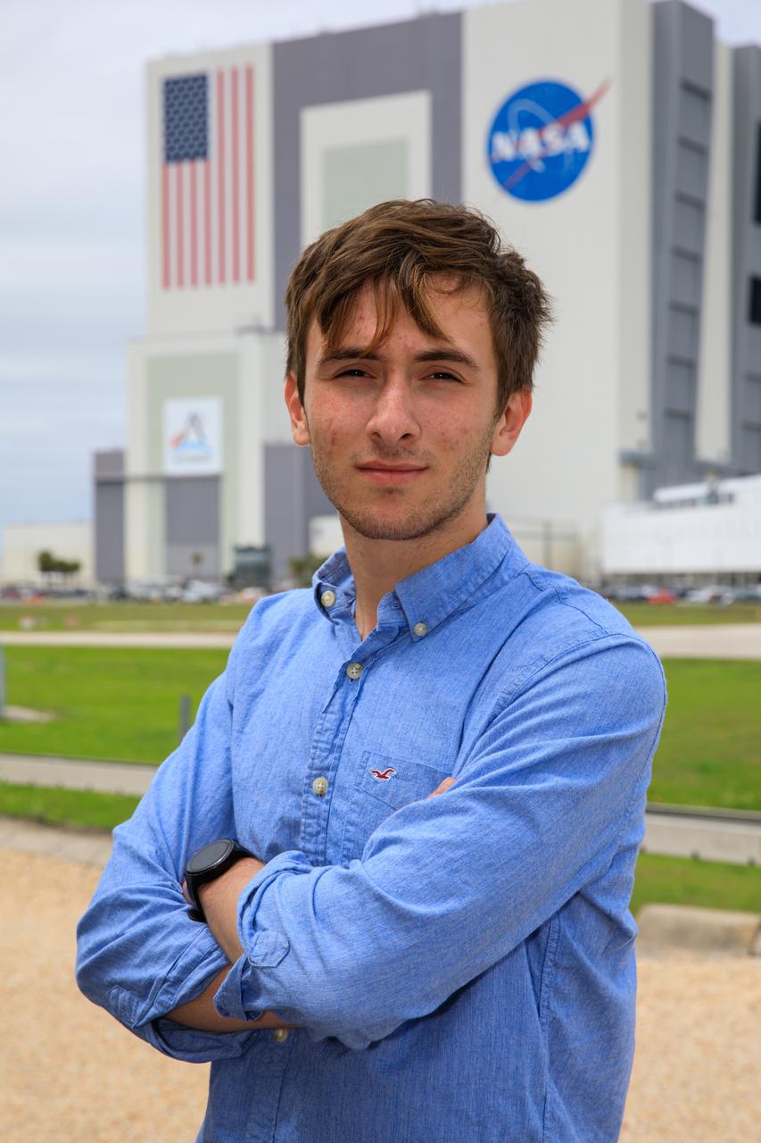
Jonah Saunders, Electrical Engineering Pathways Intern, poses in front of Vehicle Assembly Building at NASA’s Kennedy Space Center in Florida on April 17, 2023.
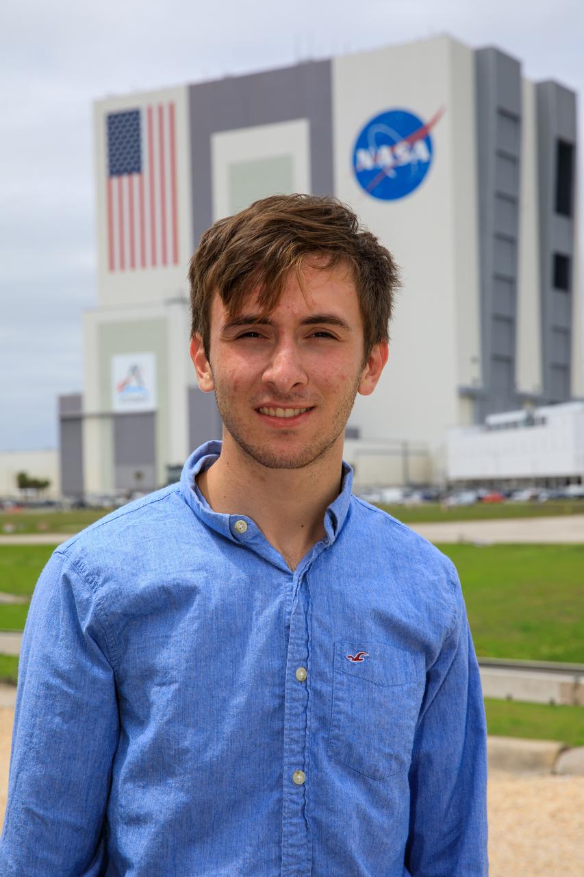
Jonah Saunders, Electrical Engineering Pathways Intern, poses in front of Vehicle Assembly Building at NASA’s Kennedy Space Center in Florida on April 17, 2023.
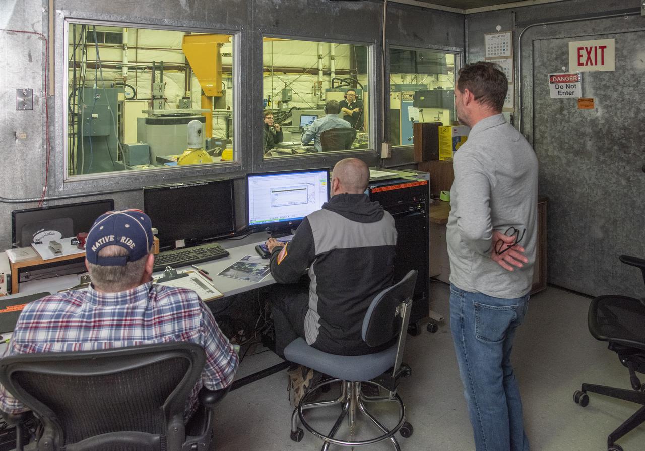
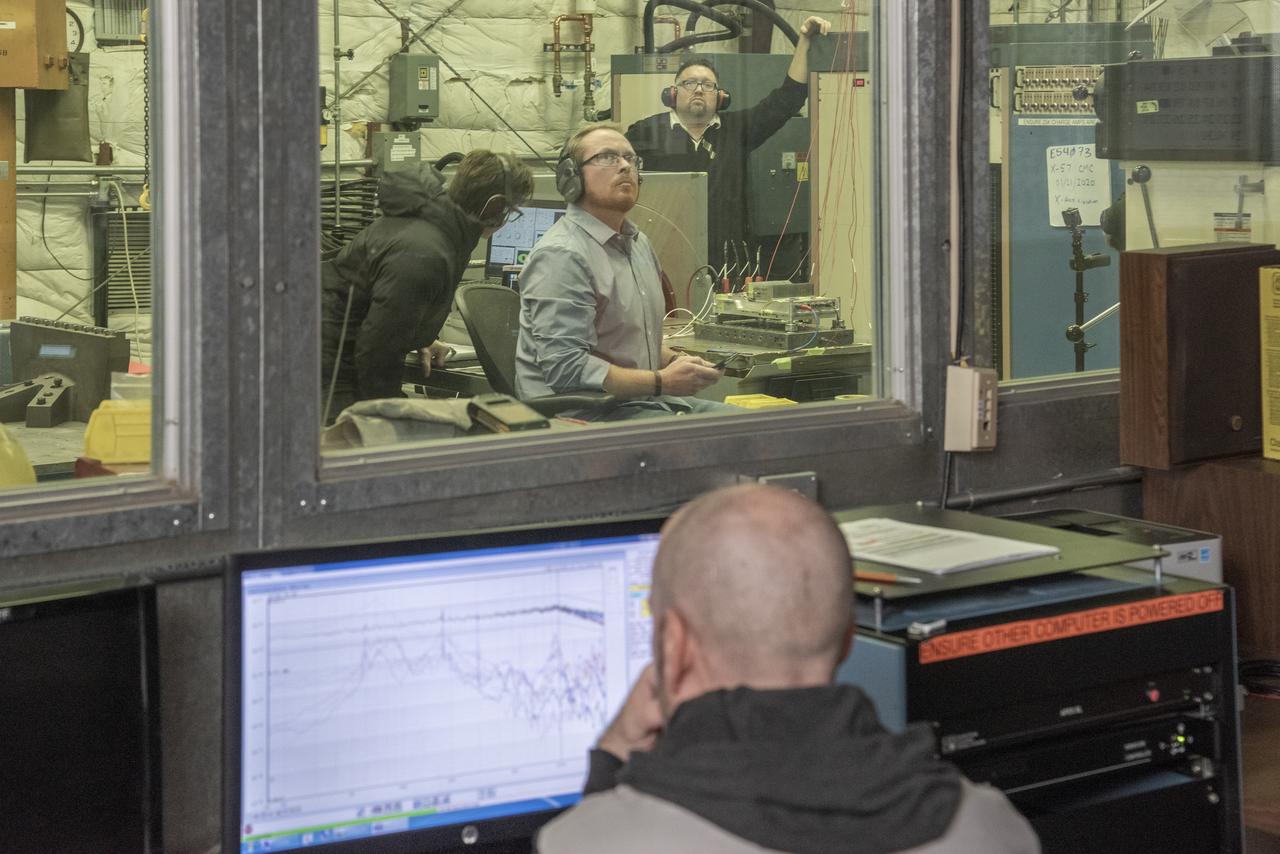
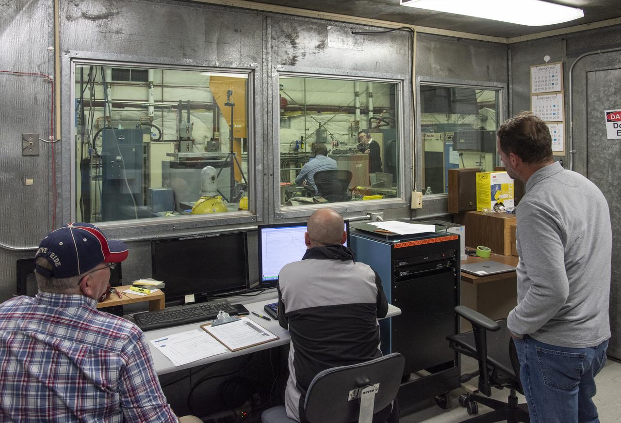
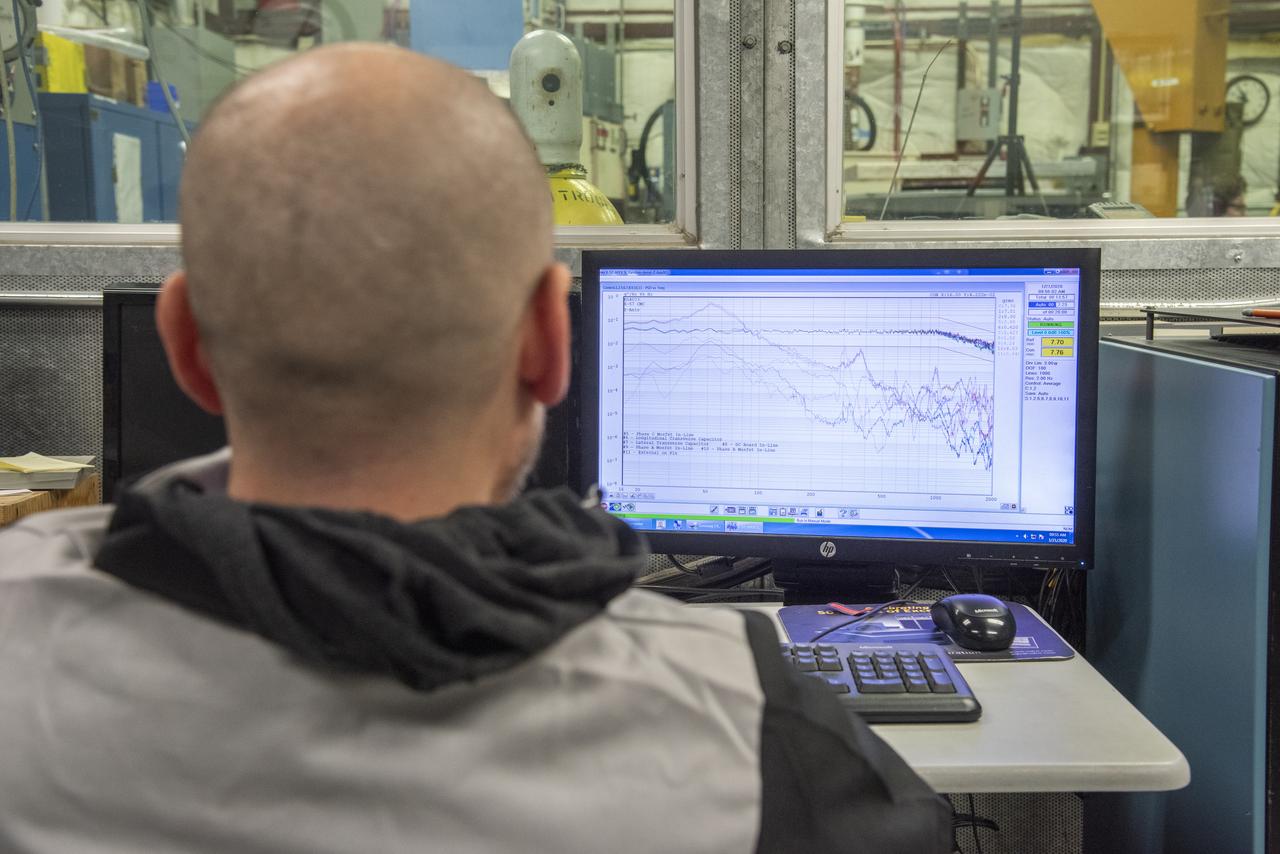
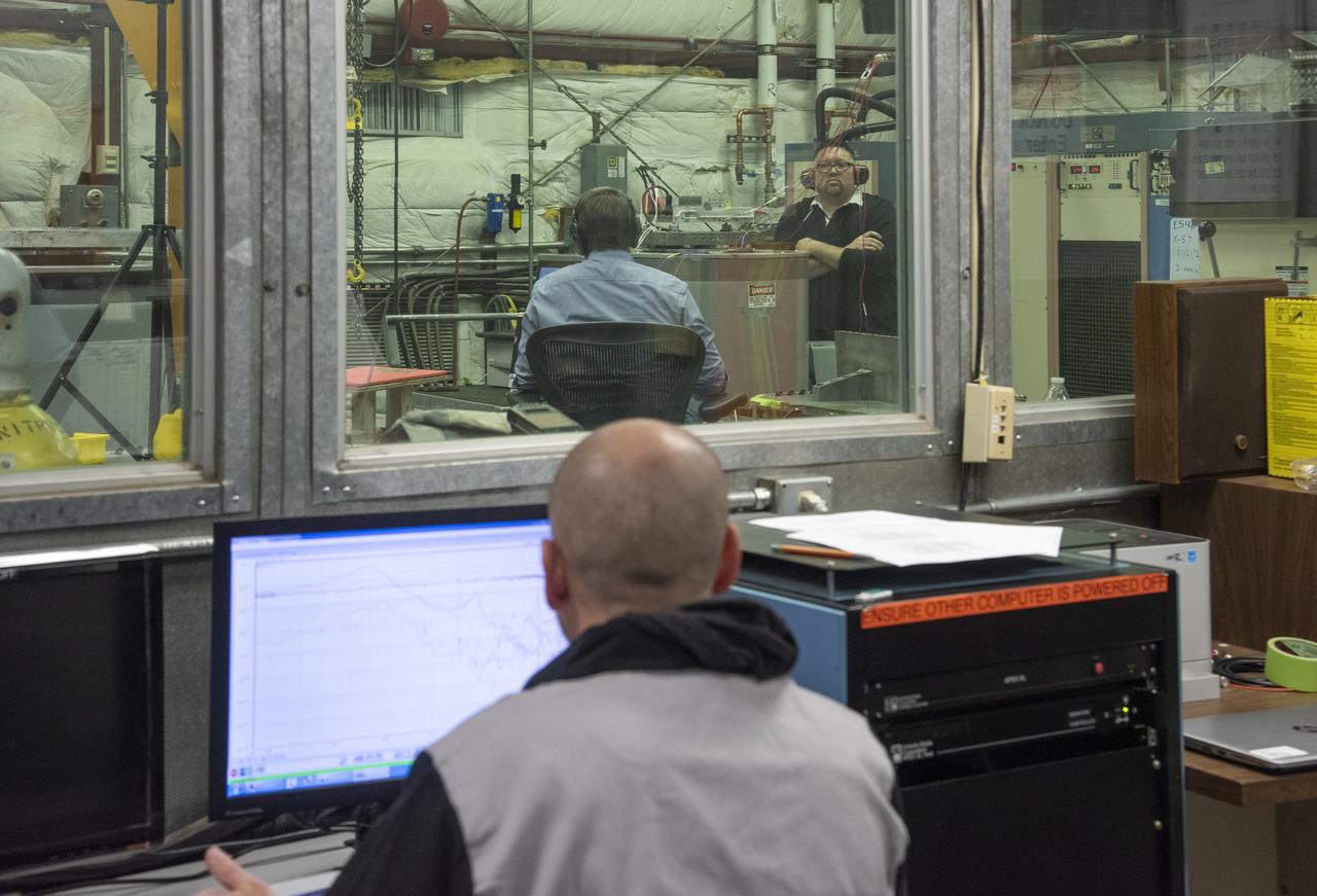
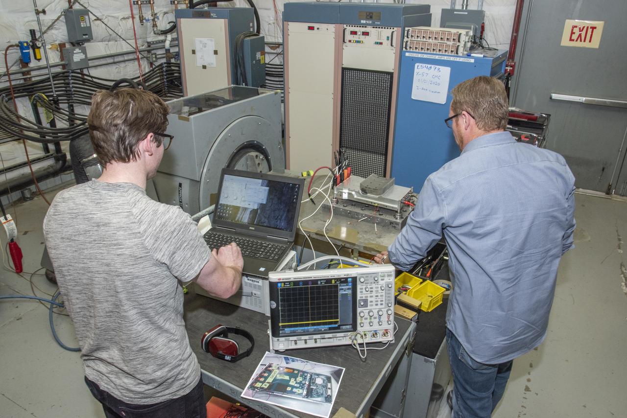
Engineers monitor data during vibration testing of a cruise motor controller for the X-57 Maxwell, NASA's first all-electric X-plane. Attached to a table at NASA Armstrong Flight Research Center's environmental lab, the cruise motor controller is exposed to specific levels of vibration, allowing NASA to examine the structural integrity of the hardware. Engineers, meanwhile, monitored data, including waveforms of electrical current, and recorded readings.
Engineers monitor data during vibration testing of a cruise motor controller for the X-57 Maxwell, NASA’s first all-electric X-plane. Attached to a table at NASA Armstrong Flight Research Center’s environmental lab, the cruise motor controller is exposed to specific levels of vibration, allowing NASA to examine the structural integrity of the hardware. Engineers, meanwhile, monitored data, including waveforms of electrical current, and recorded readings.
Engineers monitor data during vibration testing of a cruise motor controller for the X-57 Maxwell, NASA's first all-electric X-plane. Attached to a table at NASA Armstrong Flight Research Center's environmental lab, the cruise motor controller is exposed to specific levels of vibration, allowing NASA to examine the structural integrity of the hardware. Engineers, meanwhile, monitored data, including waveforms of electrical current, and recorded readings.
Mechanical Engineer Adrian Drake inspects engineering model hardware built to generate a high-voltage electric field for the Electric-Field Effects on Laminar Diffusion Flames (E-FIELD Flames) experiment of the Advanced Combustion via Microgravity Experiments (ACME) project. ACME’s small computer (i.e., the Cube) for data acquisition and control within the CIR combustion chamber is seen in the right foreground. The E-FIELD Flames tests were conducted in the Combustion Integrated Rack (CIR) on the International Space Station (ISS) in 2018.
Engineers monitor data during vibration testing of a cruise motor controller for the X-57 Maxwell, NASA's first all-electric X-plane. Attached to a table at NASA Armstrong Flight Research Center's environmental lab, the cruise motor controller is exposed to specific levels of vibration, allowing NASA to examine the structural integrity of the hardware. Engineers, meanwhile, monitored data, including waveforms of electrical current, and recorded readings.
Engineers monitor data during vibration testing of a cruise motor controller for the X-57 Maxwell, NASA's first all-electric X-plane. Attached to a table at NASA Armstrong Flight Research Center's environmental lab, the cruise motor controller is exposed to specific levels of vibration, allowing NASA to examine the structural integrity of the hardware. Engineers, meanwhile, monitored data, including waveforms of electrical current, and recorded readings.
Engineers monitor data during vibration testing of a cruise motor controller for the X-57 Maxwell, NASA’s first all-electric X-plane. Attached to a table at NASA Armstrong Flight Research Center’s environmental lab, the cruise motor controller is exposed to specific levels of vibration, allowing NASA to examine the structural integrity of the hardware. Engineers, meanwhile, monitored data, including waveforms of electrical current, and recorded readings.
Engineers monitor data during vibration testing of a cruise motor controller for the X-57 Maxwell, NASA's first all-electric X-plane. Attached to a table at NASA Armstrong Flight Research Center's environmental lab, the cruise motor controller is exposed to specific levels of vibration, allowing NASA to examine the structural integrity of the hardware. Engineers, meanwhile, monitored data, including waveforms of electrical current, and recorded readings.
Engineers monitor data during vibration testing of a cruise motor controller for the X-57 Maxwell, NASA's first all-electric X-plane. Attached to a table at NASA Armstrong Flight Research Center's environmental lab, the cruise motor controller is exposed to specific levels of vibration, allowing NASA to examine the structural integrity of the hardware. Engineers, meanwhile, monitored data, including waveforms of electrical current, and recorded readings.
Engineers monitor data during vibration testing of a cruise motor controller for the X-57 Maxwell, NASA’s first all-electric X-plane. Attached to a table at NASA Armstrong Flight Research Center’s environmental lab, the cruise motor controller is exposed to specific levels of vibration, allowing NASA to examine the structural integrity of the hardware. Engineers, meanwhile, monitored data, including waveforms of electrical current, and recorded readings.

Engineers monitor data during vibration testing of a cruise motor controller for the X-57 Maxwell, NASA's first all-electric X-plane. Attached to a table at NASA Armstrong Flight Research Center's environmental lab, the cruise motor controller is exposed to specific levels of vibration, allowing NASA to examine the structural integrity of the hardware. Engineers, meanwhile, monitored data, including waveforms of electrical current, and recorded readings.
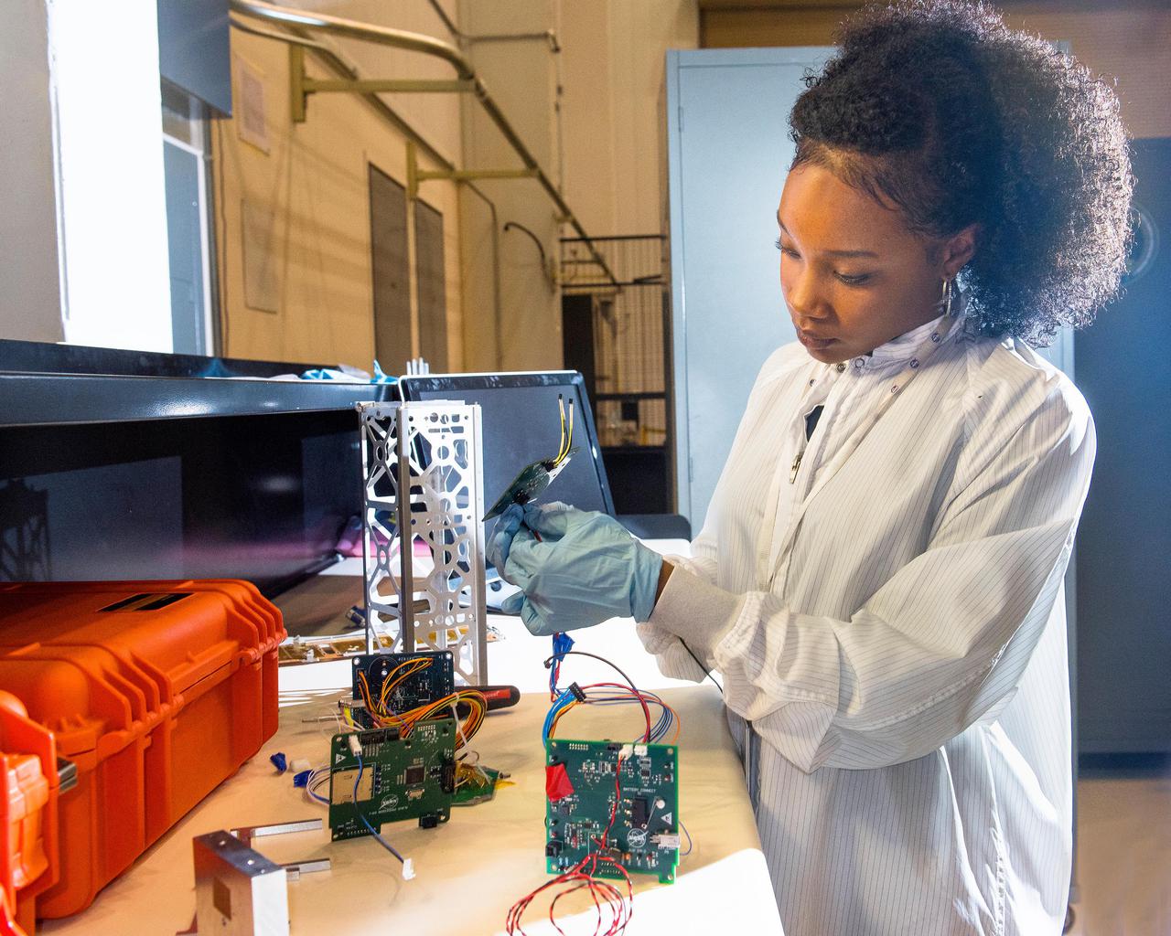
Advanced eLectrical Bus (ALBus) CubeSat: From Build to Flight A new CubeSat, launched Sunday, December 16, will test high power electric systems and the use of unique shape memory alloy (SMA) components for the first time. CubeSats are very small, lightweight satellites, about the size of a loaf of bread, and typically operate within a power range of 5-20 watts. Lower power systems are typically used in CubeSats because of size and weight limits, while higher power systems and components cause excessive heat. Completely designed and led by a team of 12 early career scientists and engineers at NASA’s Glenn Research Center in Cleveland, the Advanced Electrical Bus, or ALBus, will be the first CubeSat to demonstrate power management and distribution of a 100-watt electrical system. The CubeSat will also employ a custom-built SMA release mechanism and hinges to deploy solar arrays and conduct electricity.
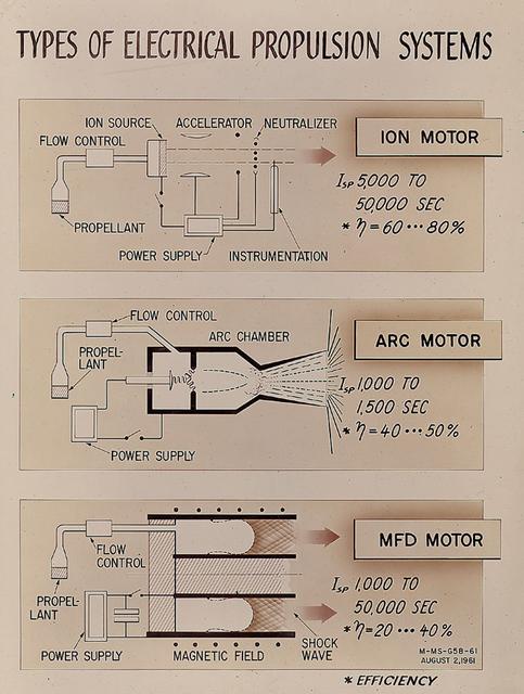
As presented by Gerhard Heller of Marshall Space Flight Center's Research Projects Division in 1961, this chart illustrates three basic types of electric propulsion systems then under consideration by NASA. The ion engine (top) utilized cesium atoms ionized by hot tungsten and accelerated by an electrostatic field to produce thrust. The arc engine (middle) achieved propulsion by heating a propellant with an electric arc and then producing an expansion of the hot gas or plasma in a convergent-divergent duct. The electromagnetic, or MFD engine (bottom) manipulated strong magnetic fields to interact with a plasma and produce acceleration.

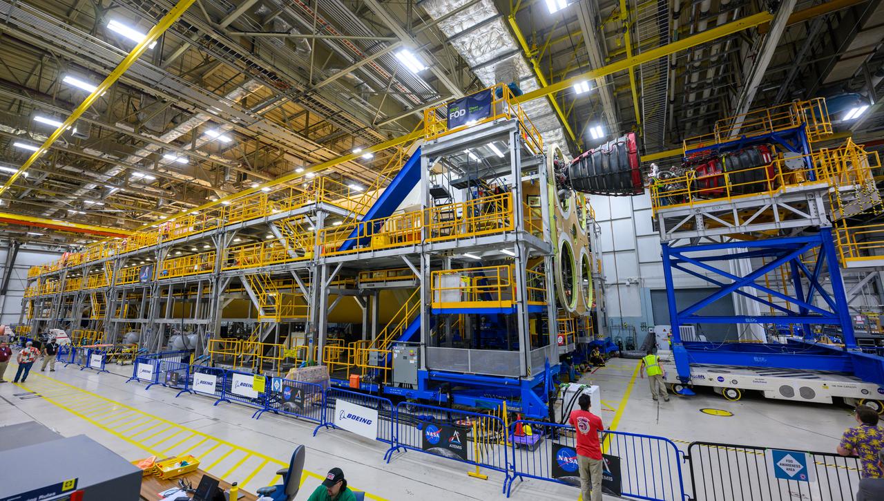
Engineers and technicians at NASA’s Michoud Assembly Facility in New Orleans have structurally mated the first of four RS-25 engines to the core stage for NASA’s Space Launch System rocket that will help power the first Artemis mission to the Moon. Integration of the RS-25 engine to the recently completed core stage structure is a collaborative, multistep process for NASA and its partners Boeing, the core stage lead contractor, and Aerojet Rocketdyne, the RS-25 engine lead contractor. To complete the installation, the technicians will now integrate the propulsion and electrical systems. The installation process will be repeated for each of the four RS-25 engines. Offering more payload mass, volume capability and energy to speed missions through space, the SLS rocket, along with NASA’s Gateway in lunar orbit and Orion, is part of NASA’s backbone for deep space exploration and the Artemis lunar program. No other rocket is capable of carrying astronauts in Orion around the Moon in a single mission.

Engineers and technicians at NASA’s Michoud Assembly Facility in New Orleans have structurally mated the first of four RS-25 engines to the core stage for NASA’s Space Launch System rocket that will help power the first Artemis mission to the Moon. Integration of the RS-25 engine to the recently completed core stage structure is a collaborative, multistep process for NASA and its partners Boeing, the core stage lead contractor, and Aerojet Rocketdyne, the RS-25 engine lead contractor. To complete the installation, the technicians will now integrate the propulsion and electrical systems. The installation process will be repeated for each of the four RS-25 engines. Offering more payload mass, volume capability and energy to speed missions through space, the SLS rocket, along with NASA’s Gateway in lunar orbit and Orion, is part of NASA’s backbone for deep space exploration and the Artemis lunar program. No other rocket is capable of carrying astronauts in Orion around the Moon in a single mission.

Engineers and technicians at NASA’s Michoud Assembly Facility in New Orleans have structurally mated the first of four RS-25 engines to the core stage for NASA’s Space Launch System rocket that will help power the first Artemis mission to the Moon. Integration of the RS-25 engine to the recently completed core stage structure is a collaborative, multistep process for NASA and its partners Boeing, the core stage lead contractor, and Aerojet Rocketdyne, the RS-25 engine lead contractor. To complete the installation, the technicians will now integrate the propulsion and electrical systems. The installation process will be repeated for each of the four RS-25 engines. Offering more payload mass, volume capability and energy to speed missions through space, the SLS rocket, along with NASA’s Gateway in lunar orbit and Orion, is part of NASA’s backbone for deep space exploration and the Artemis lunar program. No other rocket is capable of carrying astronauts in Orion around the Moon in a single mission.
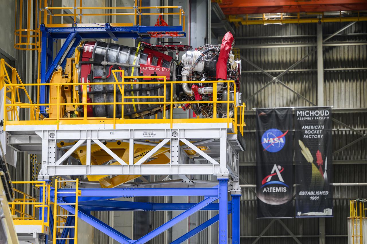
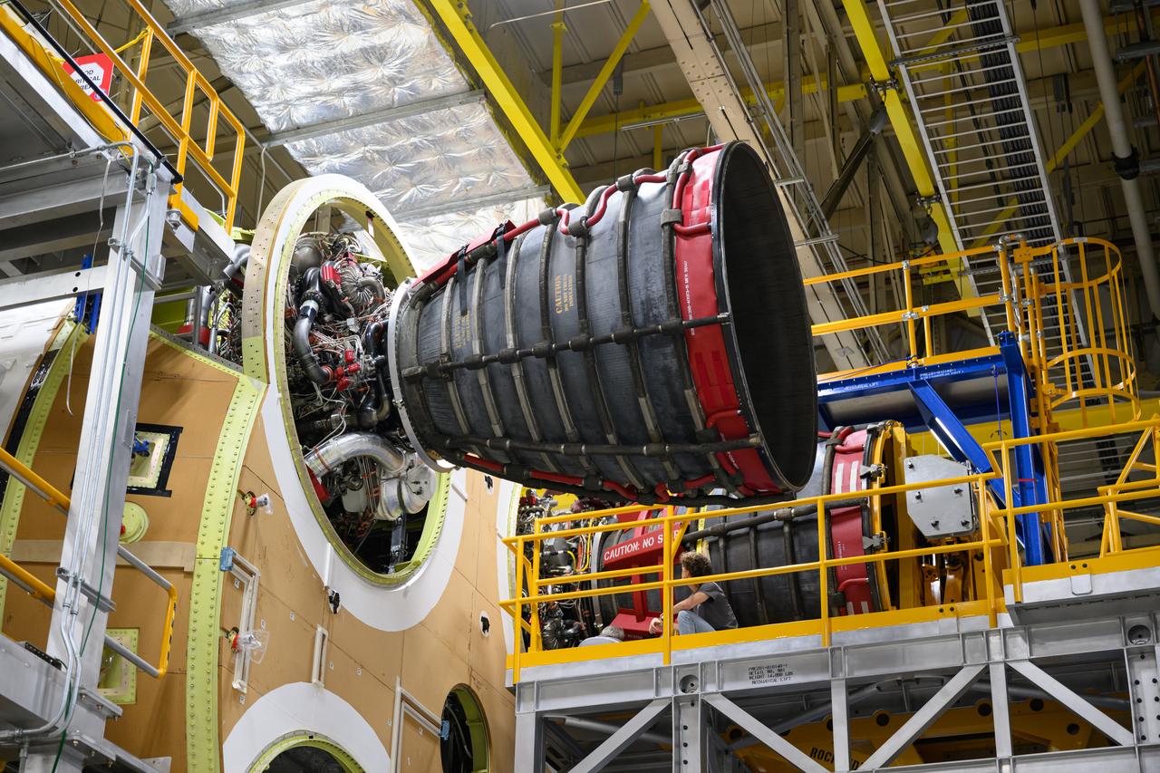
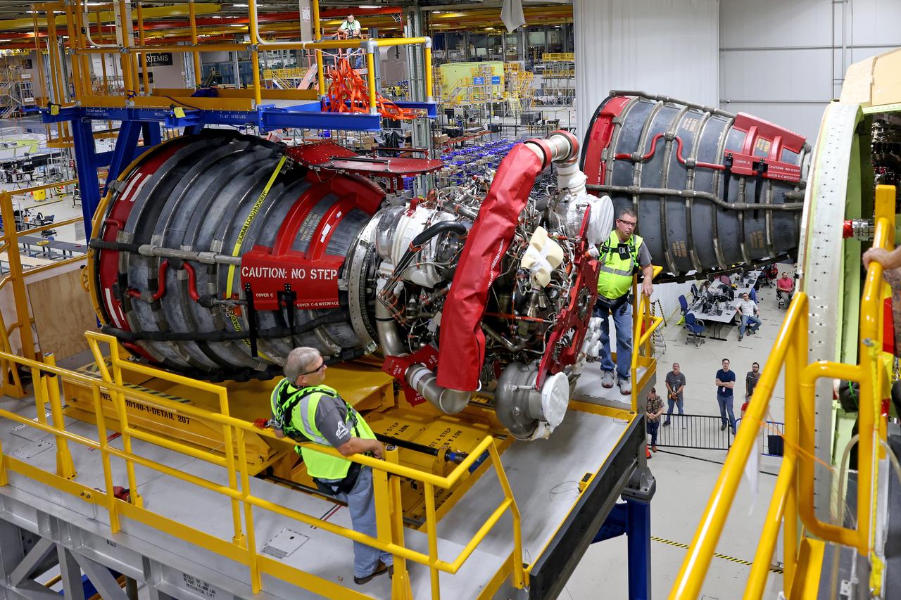
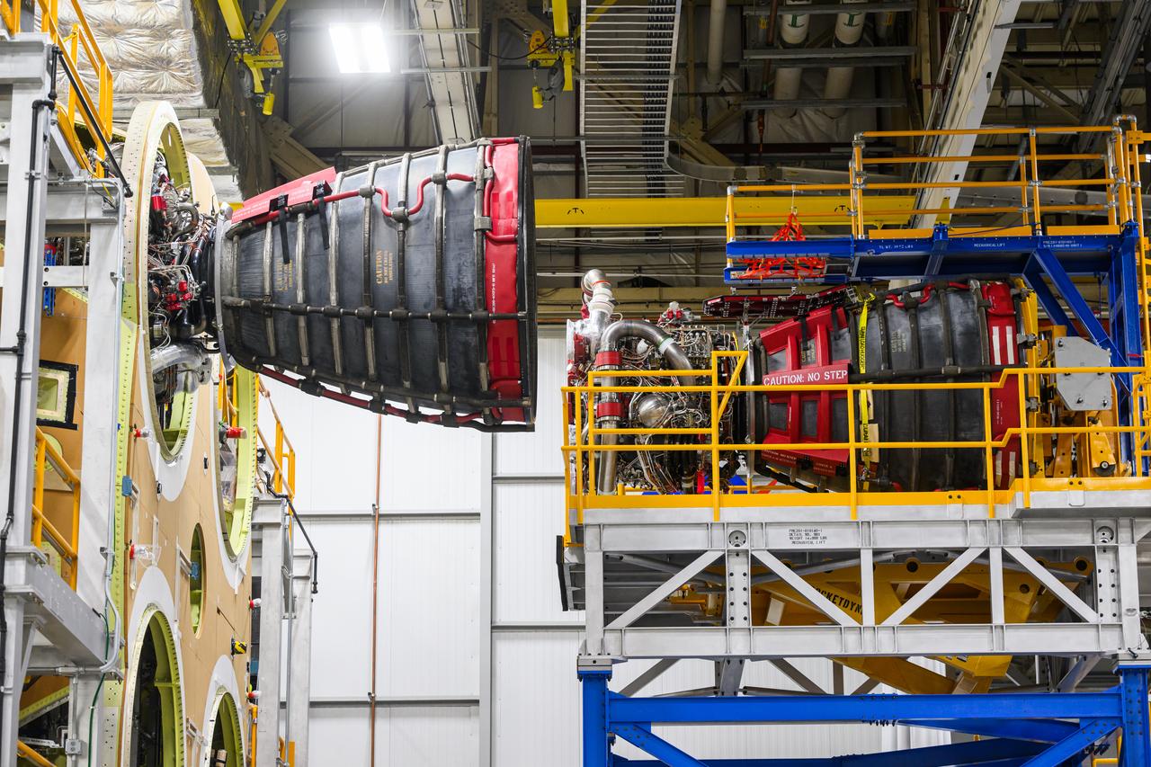
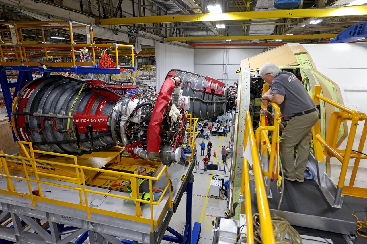
These photos and videos show how technicians at NASA’s Michoud Assembly Facility in New Orleans installed the second of four RS-25 engines onto the core stage for the agency’s SLS (Space Launch System) rocket that will help power NASA’s first crewed Artemis mission to the Moon. Crews added the second engine, with the serial number E2047 in position one, to the stage Sept. 15. The serial number for the engine installed Sept. 11 in position two on the core stage is E2059. Engineers consider the engines to be “soft” mated to the rocket stage. Following soft mate of all four engines, technicians with NASA, Aerojet Rocketdyne, an L3Harris Technologies company and the RS-25 engines lead contractor, along with Boeing, the core stage lead contractor, will fully secure the engines to the stage and integrate the propulsion and electrical systems within the structure. All four RS-25 engines are located at the base of the core stage within the engine section. NASA is working to land the first woman and first person of color on the Moon under Artemis. SLS is part of NASA’s backbone for deep space exploration, along with Orion and the Gateway in orbit around the Moon. SLS is the only rocket that can send Orion, astronauts, and supplies to the Moon in a single mission.
These photos and videos show how technicians at NASA’s Michoud Assembly Facility in New Orleans installed the second of four RS-25 engines onto the core stage for the agency’s SLS (Space Launch System) rocket that will help power NASA’s first crewed Artemis mission to the Moon. Crews added the second engine, with the serial number E2047 in position one, to the stage Sept. 15. The serial number for the engine installed Sept. 11 in position two on the core stage is E2059. Engineers consider the engines to be “soft” mated to the rocket stage. Following soft mate of all four engines, technicians with NASA, Aerojet Rocketdyne, an L3Harris Technologies company and the RS-25 engines lead contractor, along with Boeing, the core stage lead contractor, will fully secure the engines to the stage and integrate the propulsion and electrical systems within the structure. All four RS-25 engines are located at the base of the core stage within the engine section. NASA is working to land the first woman and first person of color on the Moon under Artemis. SLS is part of NASA’s backbone for deep space exploration, along with Orion and the Gateway in orbit around the Moon. SLS is the only rocket that can send Orion, astronauts, and supplies to the Moon in a single mission.
These photos and videos show how technicians at NASA’s Michoud Assembly Facility in New Orleans installed the second of four RS-25 engines onto the core stage for the agency’s SLS (Space Launch System) rocket that will help power NASA’s first crewed Artemis mission to the Moon. Crews added the second engine, with the serial number E2047 in position one, to the stage Sept. 15. The serial number for the engine installed Sept. 11 in position two on the core stage is E2059. Engineers consider the engines to be “soft” mated to the rocket stage. Following soft mate of all four engines, technicians with NASA, Aerojet Rocketdyne, an L3Harris Technologies company and the RS-25 engines lead contractor, along with Boeing, the core stage lead contractor, will fully secure the engines to the stage and integrate the propulsion and electrical systems within the structure. All four RS-25 engines are located at the base of the core stage within the engine section. NASA is working to land the first woman and first person of color on the Moon under Artemis. SLS is part of NASA’s backbone for deep space exploration, along with Orion and the Gateway in orbit around the Moon. SLS is the only rocket that can send Orion, astronauts, and supplies to the Moon in a single mission.

These photos show how technicians at NASA’s Michoud Assembly Facility in New Orleans installed the second of four RS-25 engines onto the core stage for the agency’s SLS (Space Launch System) rocket that will help power NASA’s first crewed Artemis mission to the Moon. Crews added the second engine, with the serial number E2047 in position one, to the stage Sept. 15. The serial number for the engine installed Sept. 11 in position two on the core stage is E2059. Engineers consider the engines to be “soft” mated to the rocket stage. Following soft mate of all four engines, technicians with NASA, Aerojet Rocketdyne, an L3Harris Technologies company and the RS-25 engines lead contractor, along with Boeing, the core stage lead contractor, will fully secure the engines to the stage and integrate the propulsion and electrical systems within the structure. All four RS-25 engines are located at the base of the core stage within the engine section. NASA is working to land the first woman and first person of color on the Moon under Artemis. SLS is part of NASA’s backbone for deep space exploration, along with Orion and the Gateway in orbit around the Moon. SLS is the only rocket that can send Orion, astronauts, and supplies to the Moon in a single mission.
These photos and videos show how technicians at NASA’s Michoud Assembly Facility in New Orleans installed the second of four RS-25 engines onto the core stage for the agency’s SLS (Space Launch System) rocket that will help power NASA’s first crewed Artemis mission to the Moon. Crews added the second engine, with the serial number E2047 in position one, to the stage Sept. 15. The serial number for the engine installed Sept. 11 in position two on the core stage is E2059. Engineers consider the engines to be “soft” mated to the rocket stage. Following soft mate of all four engines, technicians with NASA, Aerojet Rocketdyne, an L3Harris Technologies company and the RS-25 engines lead contractor, along with Boeing, the core stage lead contractor, will fully secure the engines to the stage and integrate the propulsion and electrical systems within the structure. All four RS-25 engines are located at the base of the core stage within the engine section. NASA is working to land the first woman and first person of color on the Moon under Artemis. SLS is part of NASA’s backbone for deep space exploration, along with Orion and the Gateway in orbit around the Moon. SLS is the only rocket that can send Orion, astronauts, and supplies to the Moon in a single mission.

These photos and videos show how technicians at NASA’s Michoud Assembly Facility in New Orleans installed the second of four RS-25 engines onto the core stage for the agency’s SLS (Space Launch System) rocket that will help power NASA’s first crewed Artemis mission to the Moon. Crews added the second engine, with the serial number E2047 in position one, to the stage Sept. 15. The serial number for the engine installed Sept. 11 in position two on the core stage is E2059. Engineers consider the engines to be “soft” mated to the rocket stage. Following soft mate of all four engines, technicians with NASA, Aerojet Rocketdyne, an L3Harris Technologies company and the RS-25 engines lead contractor, along with Boeing, the core stage lead contractor, will fully secure the engines to the stage and integrate the propulsion and electrical systems within the structure. All four RS-25 engines are located at the base of the core stage within the engine section. NASA is working to land the first woman and first person of color on the Moon under Artemis. SLS is part of NASA’s backbone for deep space exploration, along with Orion and the Gateway in orbit around the Moon. SLS is the only rocket that can send Orion, astronauts, and supplies to the Moon in a single mission.
These photos and videos show how technicians at NASA’s Michoud Assembly Facility in New Orleans installed the second of four RS-25 engines onto the core stage for the agency’s SLS (Space Launch System) rocket that will help power NASA’s first crewed Artemis mission to the Moon. Crews added the second engine, with the serial number E2047 in position one, to the stage Sept. 15. The serial number for the engine installed Sept. 11 in position two on the core stage is E2059. Engineers consider the engines to be “soft” mated to the rocket stage. Following soft mate of all four engines, technicians with NASA, Aerojet Rocketdyne, an L3Harris Technologies company and the RS-25 engines lead contractor, along with Boeing, the core stage lead contractor, will fully secure the engines to the stage and integrate the propulsion and electrical systems within the structure. All four RS-25 engines are located at the base of the core stage within the engine section. NASA is working to land the first woman and first person of color on the Moon under Artemis. SLS is part of NASA’s backbone for deep space exploration, along with Orion and the Gateway in orbit around the Moon. SLS is the only rocket that can send Orion, astronauts, and supplies to the Moon in a single mission.

This photo shows the second RS-25 engine attached to the core stage for NASA’s Space Launch System rocket for the agency’s Artemis I mission to the Moon. Engineers and technicians at NASA’s Michoud Assembly Facility in New Orleans structurally mated the second of four engines to the stage on Oct. 30 and are currently integrating the propulsion and electrical systems within the structure to complete the installation. Integration of the RS-25 engines to the recently completed core stage structure is a collaborative, multistep process for NASA and its partners Boeing, the core stage lead contractor, and Aerojet Rocketdyne, the RS-25 engines lead contractor. The four RS-25 engines for Artemis I are modified heritage flight hardware from the Space Shuttle Program, ensuring high performance and reliability to power NASA’s next generation lunar missions. Each engine also has a special identification number, and NASA keeps a history of which engines are used on each mission. The second engine, Engine 2045, has flown on several shuttle missions, including the mission that returned NASA astronaut John Glenn to space in 1998 as well as the first and only shuttle launch to occur on Independence Day in 2006.
These photos and videos show how technicians at NASA’s Michoud Assembly Facility in New Orleans installed the second of four RS-25 engines onto the core stage for the agency’s SLS (Space Launch System) rocket that will help power NASA’s first crewed Artemis mission to the Moon. Crews added the second engine, with the serial number E2047 in position one, to the stage Sept. 15. The serial number for the engine installed Sept. 11 in position two on the core stage is E2059. Engineers consider the engines to be “soft” mated to the rocket stage. Following soft mate of all four engines, technicians with NASA, Aerojet Rocketdyne, an L3Harris Technologies company and the RS-25 engines lead contractor, along with Boeing, the core stage lead contractor, will fully secure the engines to the stage and integrate the propulsion and electrical systems within the structure. All four RS-25 engines are located at the base of the core stage within the engine section. NASA is working to land the first woman and first person of color on the Moon under Artemis. SLS is part of NASA’s backbone for deep space exploration, along with Orion and the Gateway in orbit around the Moon. SLS is the only rocket that can send Orion, astronauts, and supplies to the Moon in a single mission.
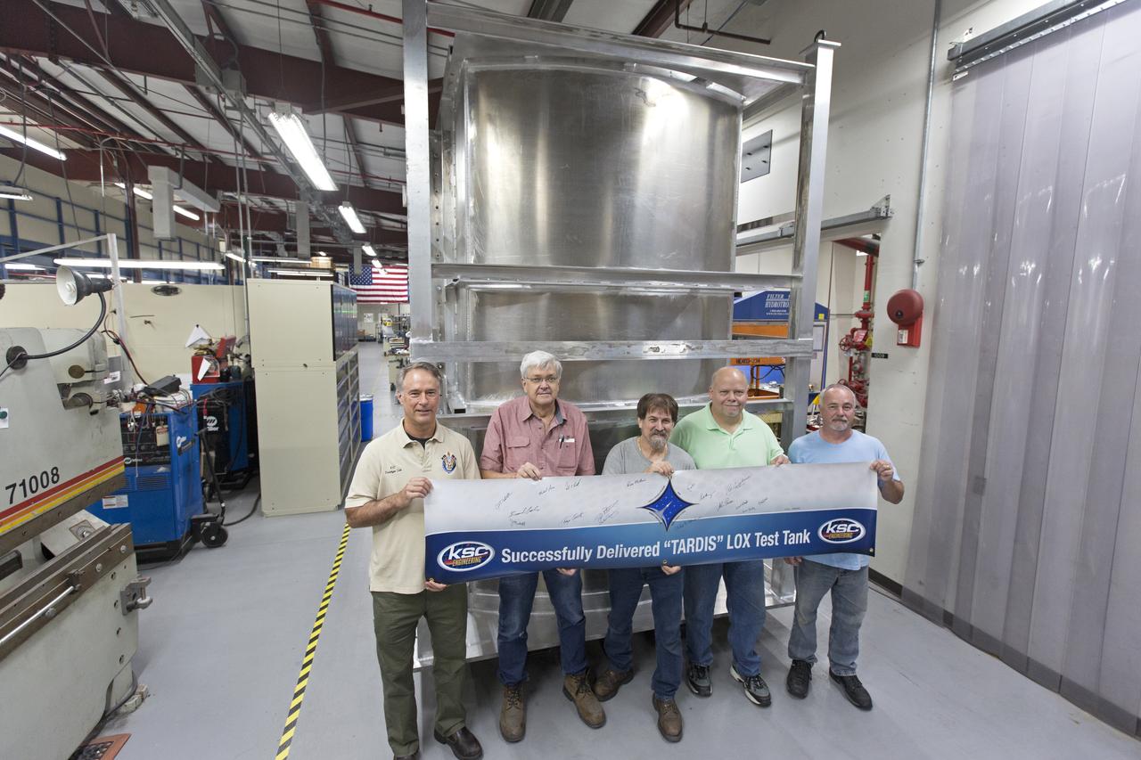
Inside the Prototype Development Laboratory at NASA's Kennedy Space Center in Florida, engineers and technicians hold a banner marking the successful delivery of a liquid oxygen test tank called Tardis. From left, are Todd Steinrock, chief, Fabrication and Development Branch, Prototype Development Lab; David McLaughlin, electrical engineering technician; Phil Stroda, mechanical engineering technician; Perry Dickey, lead electrical engineering technician; and Harold McAmis, lead mechanical engineering technician. Engineers and technicians worked together to develop the tank and build it at the lab to support cryogenic testing at Johnson Space Center's White Sands Test Facility in Las Cruces, New Mexico. The 12-foot-tall, 3,810-pound aluminum tank will be shipped to White Sands for testing.
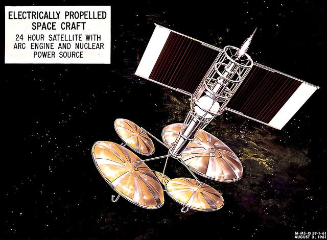
This 1960 artist's concept shows a 24-hour communication satellite design incorporating an arc engine with a nuclear power source. The concept was one of many missions proposed by the Marshall Space Flight Center for electrically-propelled spacecraft.
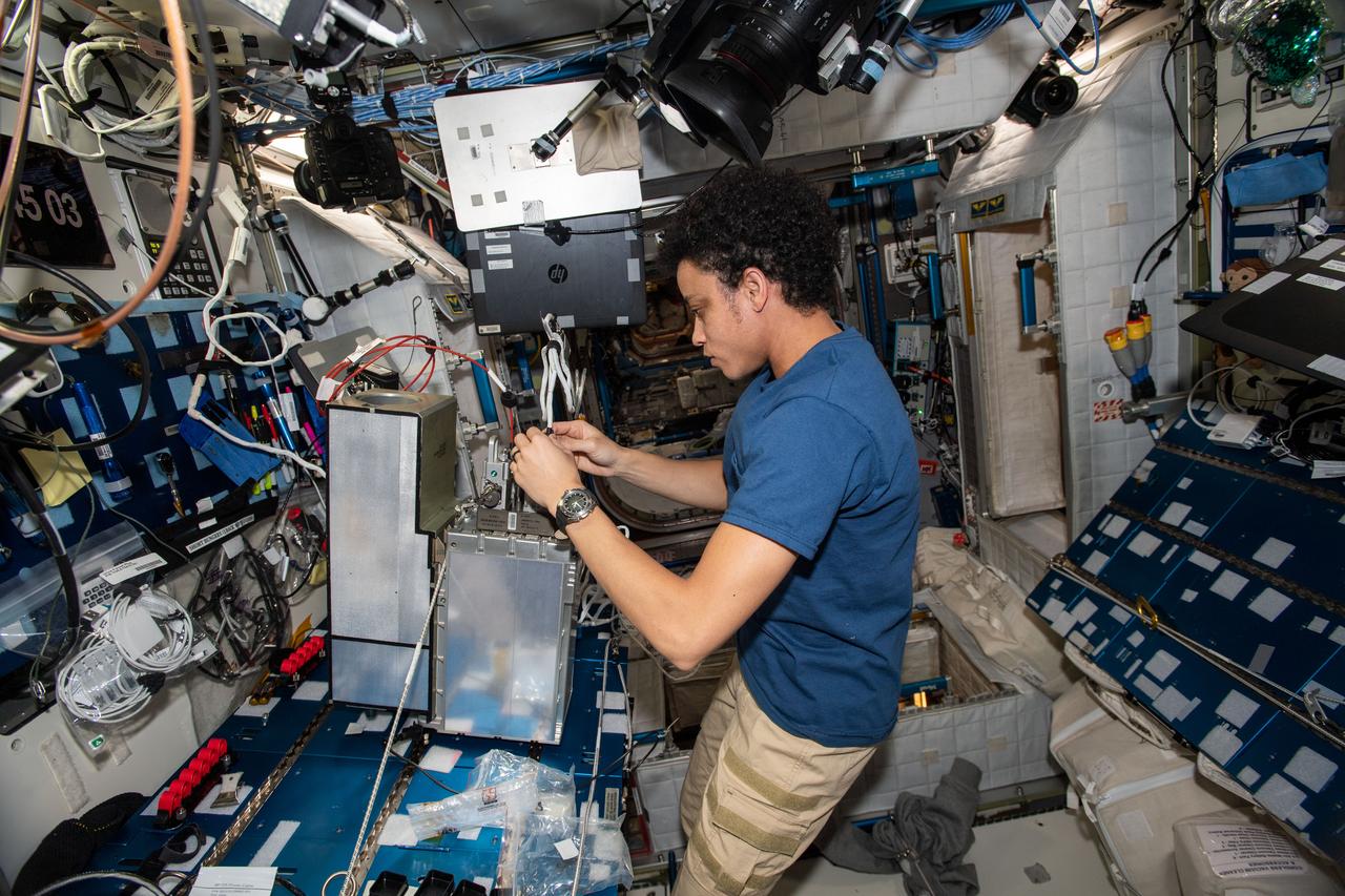
iss067e175853 (July 7, 2022) --- Expedition 67 Flight Engineer and NASA astronaut Jessica Watkins works on electrical system components inside the International Space Station's Harmony module.
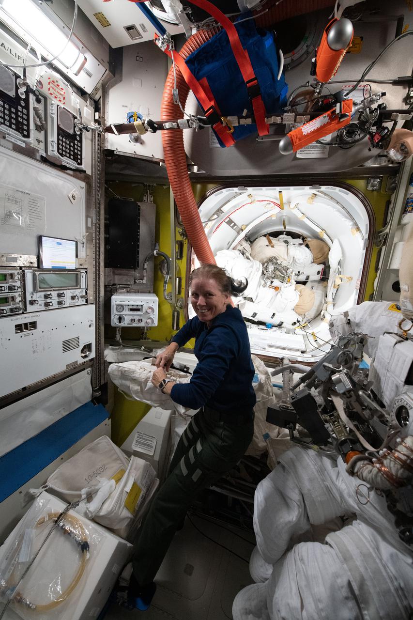
iss064e022228 (Jan. 11, 2021) --- NASA astronaut and Expedition 64 Flight Engineer Shannon Walker works inside the U.S. Quest airlock servicing a variety of life support hardware and electrical components.
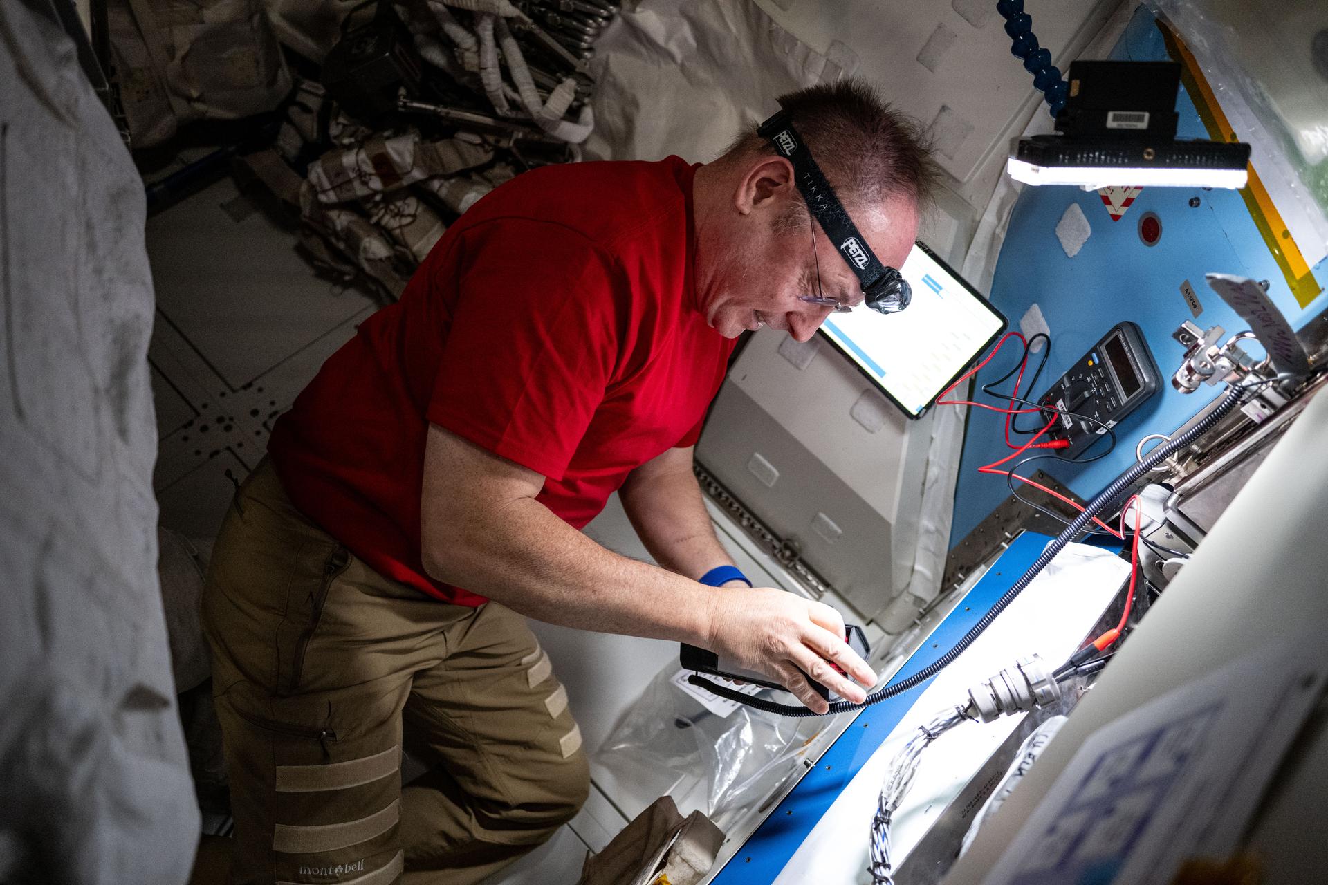
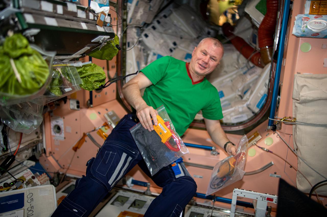
iss073e0698609 (Sept. 16, 2025) --- NASA astronaut and Expedition 73 Flight Engineer Mike Fincke performs electrical resistance measurements on the thermal control system inside the International Space Station's Quest airlock.
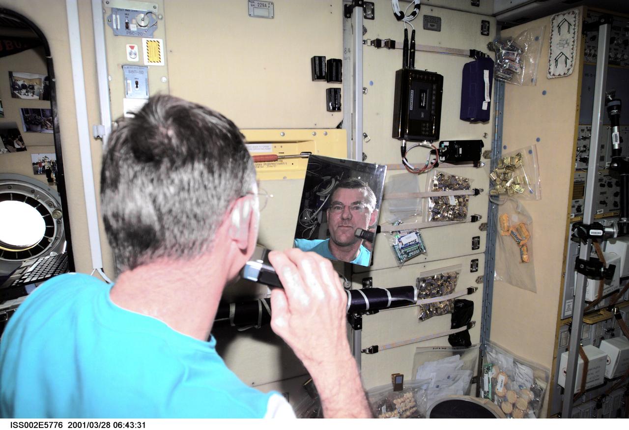
ISS002-E-5776 (28 March 2001) --- James S. Voss, Expedition Two flight engineer, shaves with an electric razor in the Zvezda Service Module. The image was taken with a digital still camera.
iss065e006630 (April 27, 2021) --- Roscosmos cosmonaut and Expedition 65 Flight Engineer Oleg Novitskiy pauses for a portrait during electrical maintenance work aboard the International Space Station.
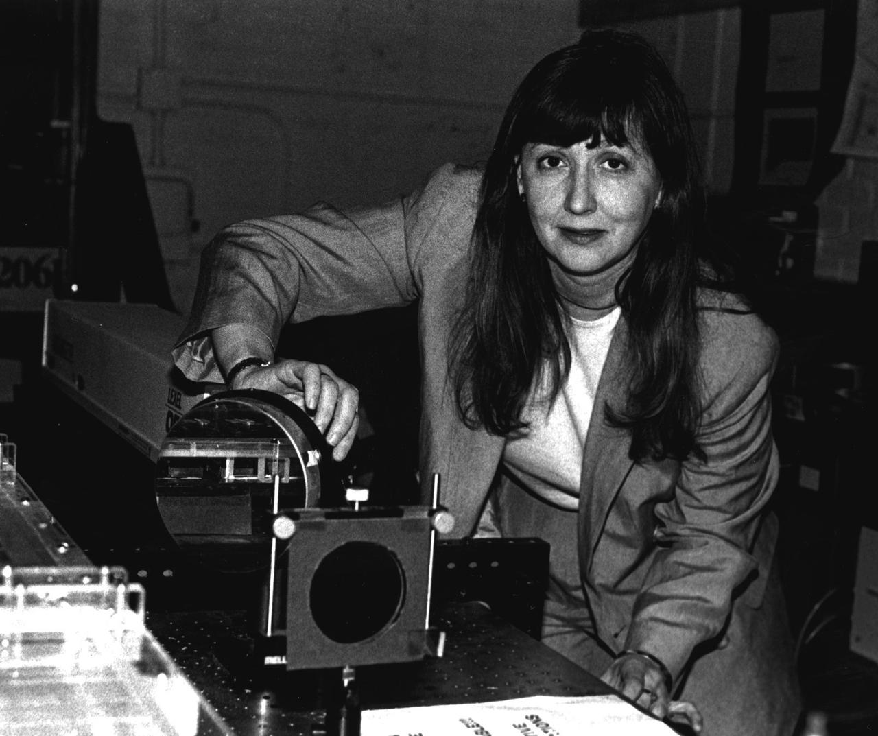
Dr. Cila Herman, G.W.C. Whiting School of Engineering, Johns Hopkins University, Baltimore. She is the principal investigator for the Experimental Investigation of Pool Boiling Heat Transfer Enhancement in Microgravity in the Presence of Electric Fields.
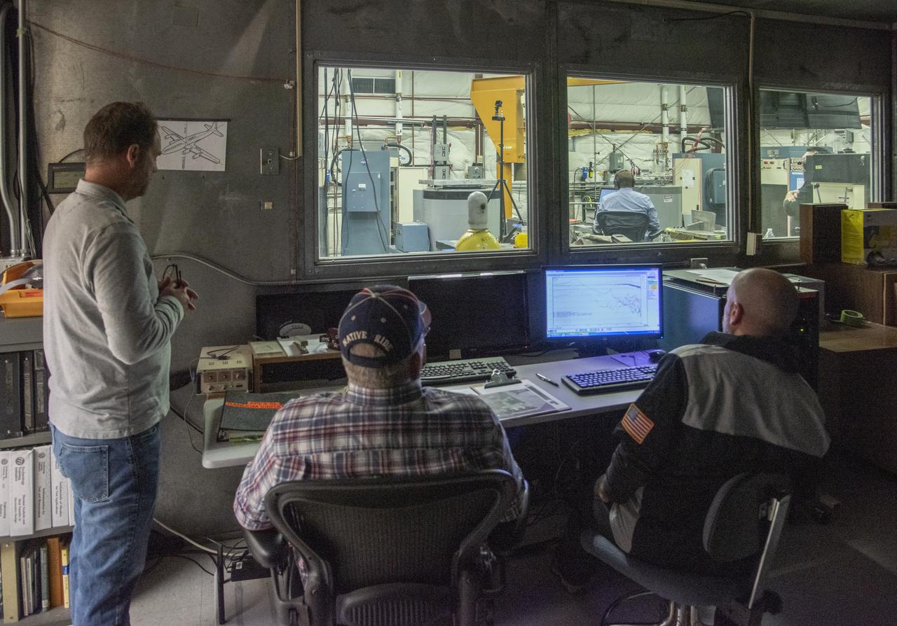
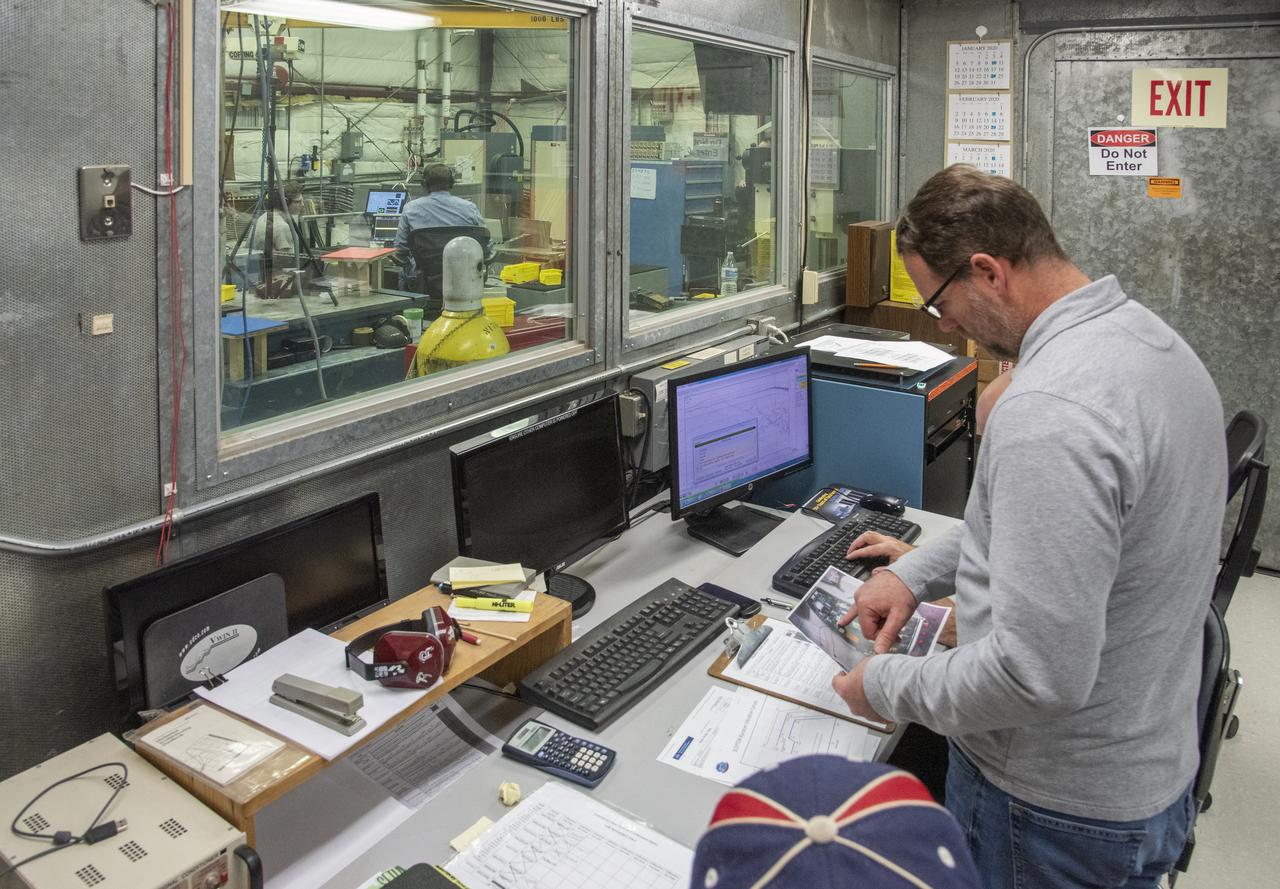
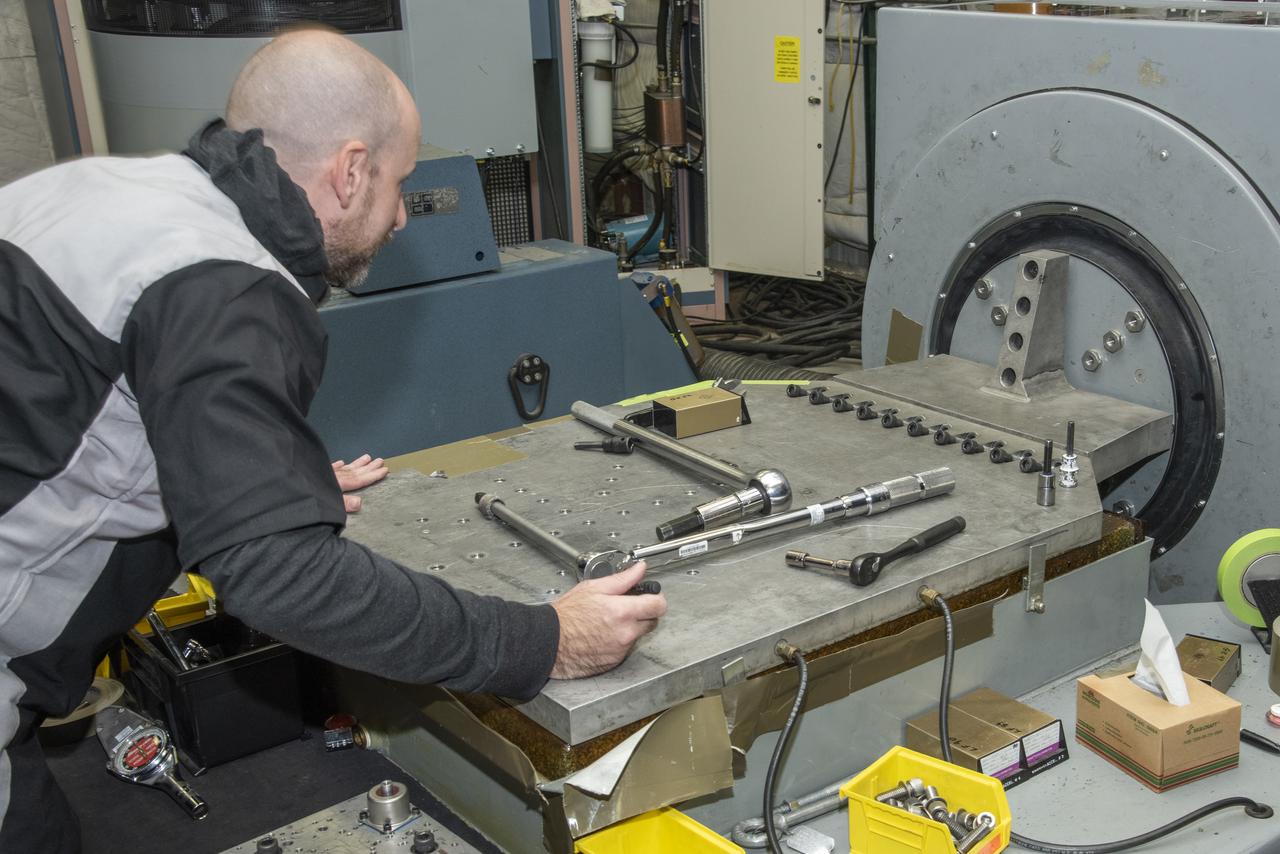
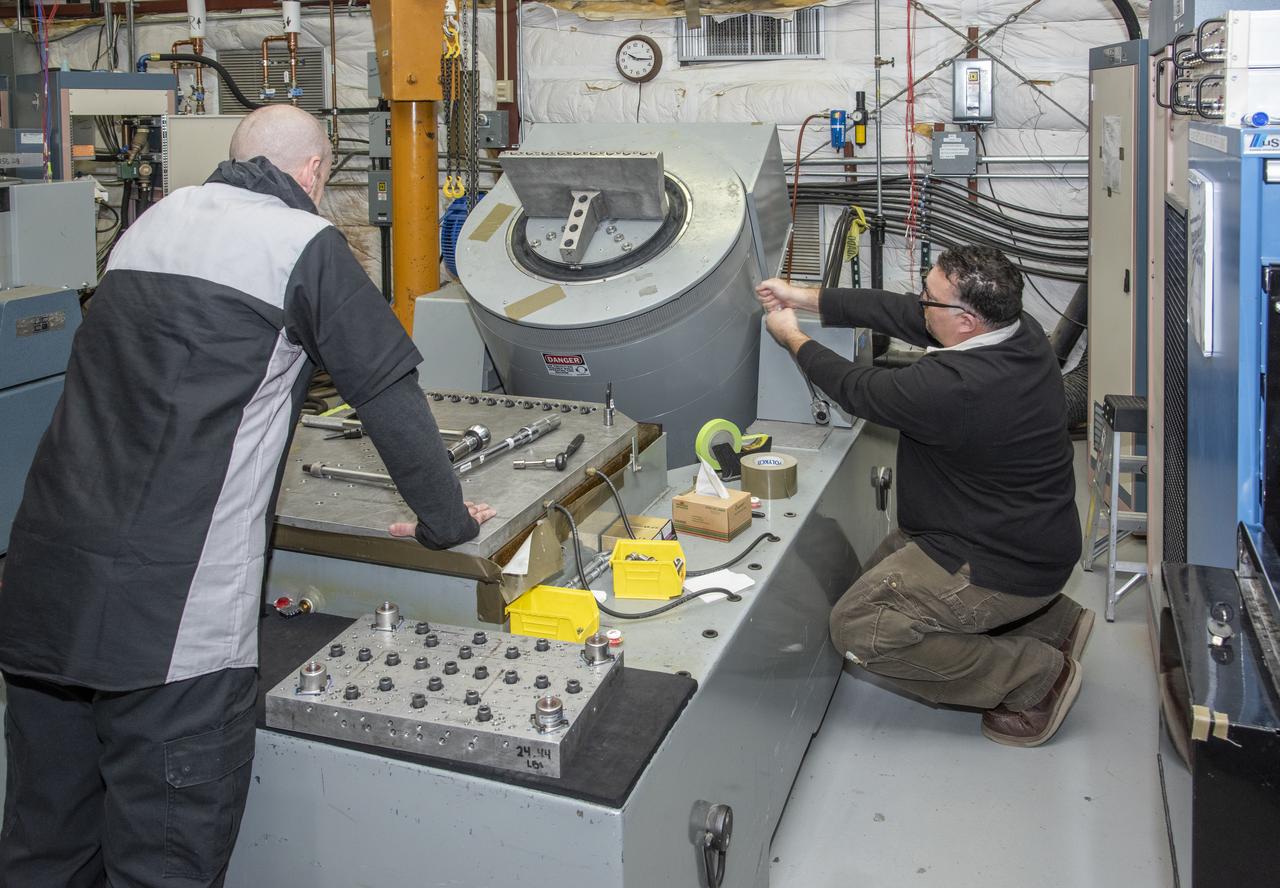
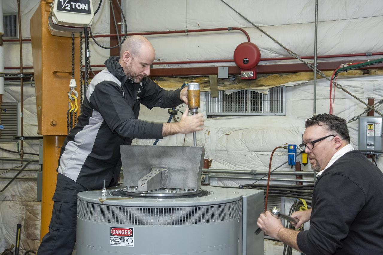
Engineers from NASA's Armstrong Flight Research Center and Empirical Systems Aerospace prepare a cruise motor controller, planned to be used on NASA's all-electric X-57 Maxwell, for vibration testing at Armstrong's environmental lab. Testing the cruise motor controller at various vibration levels, based on baseline flight testing in the project's first phase, helps ensure that the hardware will withstand similar vibration in flight conditions. X-57, NASA's first all-electric experimental aircraft, or X-plane, will fly in its first all-electric configuration in 2020.
Engineers from NASA’s Armstrong Flight Research Center and Empirical Systems Aerospace prepare a cruise motor controller, planned to be used on NASA’s all-electric X-57 Maxwell, for vibration testing at Armstrong’s environmental lab. Testing the cruise motor controller at various vibration levels, based on baseline flight testing in the project’s first phase, helps ensure that the hardware will withstand similar vibration in flight conditions. X-57, NASA’s first all-electric experimental aircraft, or X-plane, will fly in its first all-electric configuration in 2020.
The X-57 operations crew at NASA's Armstrong Flight Research Center prepare for telemetry testing on NASA's first all-electric X-plane, the X-57 Maxwell. Shown here in its first all-electric configuration, known as Mod II, X-57's series of functional tests helps engineers confirm that the vehicle will be ready for taxi and flight tests, and the telemetry testing confirms the ability of the aircraft to transmit location and test data to the ground. X-57 will help set certification standards for emerging electric aircraft markets.
Engineers from NASA's Armstrong Flight Research Center and Empirical Systems Aerospace prepare a cruise motor controller, planned to be used on NASA's all-electric X-57 Maxwell, for vibration testing at Armstrong's environmental lab. Testing the cruise motor controller at various vibration levels, based on baseline flight testing in the project's first phase, helps ensure that the hardware will withstand similar vibration in flight conditions. X-57, NASA's first all-electric experimental aircraft, or X-plane, will fly in its first all-electric configuration in 2020.
Engineers from NASA’s Armstrong Flight Research Center and Empirical Systems Aerospace prepare a cruise motor controller, planned to be used on NASA’s all-electric X-57 Maxwell, for vibration testing at Armstrong’s environmental lab. Testing the cruise motor controller at various vibration levels, based on baseline flight testing in the project’s first phase, helps ensure that the hardware will withstand similar vibration in flight conditions. X-57, NASA’s first all-electric experimental aircraft, or X-plane, will fly in its first all-electric configuration in 2020.
Engineers from NASA's Armstrong Flight Research Center and Empirical Systems Aerospace prepare a cruise motor controller, planned to be used on NASA's all-electric X-57 Maxwell, for vibration testing at Armstrong's environmental lab. Testing the cruise motor controller at various vibration levels, based on baseline flight testing in the project's first phase, helps ensure that the hardware will withstand similar vibration in flight conditions. X-57, NASA's first all-electric experimental aircraft, or X-plane, will fly in its first all-electric configuration in 2020.
Engineers from NASA's Armstrong Flight Research Center and Empirical Systems Aerospace prepare a cruise motor controller, planned to be used on NASA's all-electric X-57 Maxwell, for vibration testing at Armstrong's environmental lab. Testing the cruise motor controller at various vibration levels, based on baseline flight testing in the project's first phase, helps ensure that the hardware will withstand similar vibration in flight conditions. X-57, NASA's first all-electric experimental aircraft, or X-plane, will fly in its first all-electric configuration in 2020.
Engineers from NASA's Armstrong Flight Research Center and Empirical Systems Aerospace prepare a cruise motor controller, planned to be used on NASA's all-electric X-57 Maxwell, for vibration testing at Armstrong's environmental lab. Testing the cruise motor controller at various vibration levels, based on baseline flight testing in the project's first phase, helps ensure that the hardware will withstand similar vibration in flight conditions. X-57, NASA's first all-electric experimental aircraft, or X-plane, will fly in its first all-electric configuration in 2020.
Engineers from NASA's Armstrong Flight Research Center and Empirical Systems Aerospace prepare a cruise motor controller, planned to be used on NASA's all-electric X-57 Maxwell, for vibration testing at Armstrong's environmental lab. Testing the cruise motor controller at various vibration levels, based on baseline flight testing in the project's first phase, helps ensure that the hardware will withstand similar vibration in flight conditions. X-57, NASA's first all-electric experimental aircraft, or X-plane, will fly in its first all-electric configuration in 2020.
Engineers from NASA's Armstrong Flight Research Center and Empirical Systems Aerospace prepare a cruise motor controller, planned to be used on NASA's all-electric X-57 Maxwell, for vibration testing at Armstrong's environmental lab. Testing the cruise motor controller at various vibration levels, based on baseline flight testing in the project's first phase, helps ensure that the hardware will withstand similar vibration in flight conditions. X-57, NASA's first all-electric experimental aircraft, or X-plane, will fly in its first all-electric configuration in 2020.
Engineers from NASA's Armstrong Flight Research Center and Empirical Systems Aerospace prepare a cruise motor controller, planned to be used on NASA's all-electric X-57 Maxwell, for vibration testing at Armstrong's environmental lab. Testing the cruise motor controller at various vibration levels, based on baseline flight testing in the project's first phase, helps ensure that the hardware will withstand similar vibration in flight conditions. X-57, NASA's first all-electric experimental aircraft, or X-plane, will fly in its first all-electric configuration in 2020.
Engineers from NASA's Armstrong Flight Research Center and Empirical Systems Aerospace prepare a cruise motor controller, planned to be used on NASA's all-electric X-57 Maxwell, for vibration testing at Armstrong's environmental lab. Testing the cruise motor controller at various vibration levels, based on baseline flight testing in the project's first phase, helps ensure that the hardware will withstand similar vibration in flight conditions. X-57, NASA's first all-electric experimental aircraft, or X-plane, will fly in its first all-electric configuration in 2020.