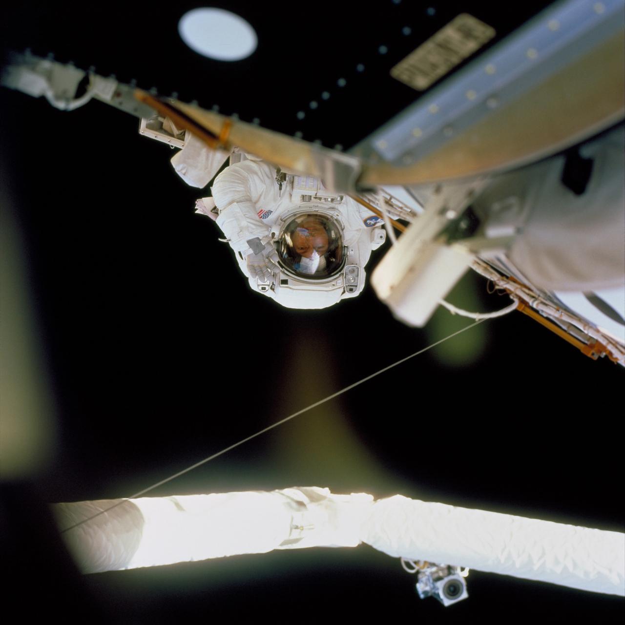
In this image, STS-97 astronaut and mission specialist Carlos I. Noriega waves at a crew member inside Endeavor's cabin during the mission's final session of Extravehicular Activity (EVA). Launched aboard the Space Shuttle Orbiter Endeavor on November 30, 2000, the STS-97 mission's primary objective was the delivery, assembly, and activation of the U.S. electrical power system onboard the International Space Station (ISS). The electrical power system, which is built into a 73-meter (240-foot) long solar array structure consists of solar arrays, radiators, batteries, and electronics. The entire 15.4-metric ton (17-ton) package is called the P6 Integrated Truss Segment, and is the heaviest and largest element yet delivered to the station aboard a space shuttle. The electrical system will eventually provide the power necessary for the first ISS crews to live and work in the U.S. segment.
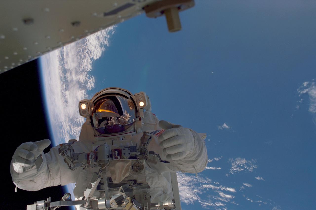
In this image, planet Earth, some 235 statute miles away, forms the back drop for this photo of STS-97 astronaut and mission specialist Joseph R. Tanner, taken during the third of three space walks. The mission's goal was to perform the delivery, assembly, and activation of the U.S. electrical power system onboard the International Space Station (ISS). The electrical power system, which is built into a 73-meter (240-foot) long solar array structure consists of solar arrays, radiators, batteries, and electronics. The entire 15.4-metric ton (17-ton) package is called the P6 Integrated Truss Segment, and is the heaviest and largest element yet delivered to the station aboard a space shuttle. The electrical system will eventually provide the power necessary for the first ISS crews to live and work in the U.S. segment. The STS-97 crew of five launched aboard the Space Shuttle Orbiter Endeavor on November 30, 2000 for an 11 day mission.
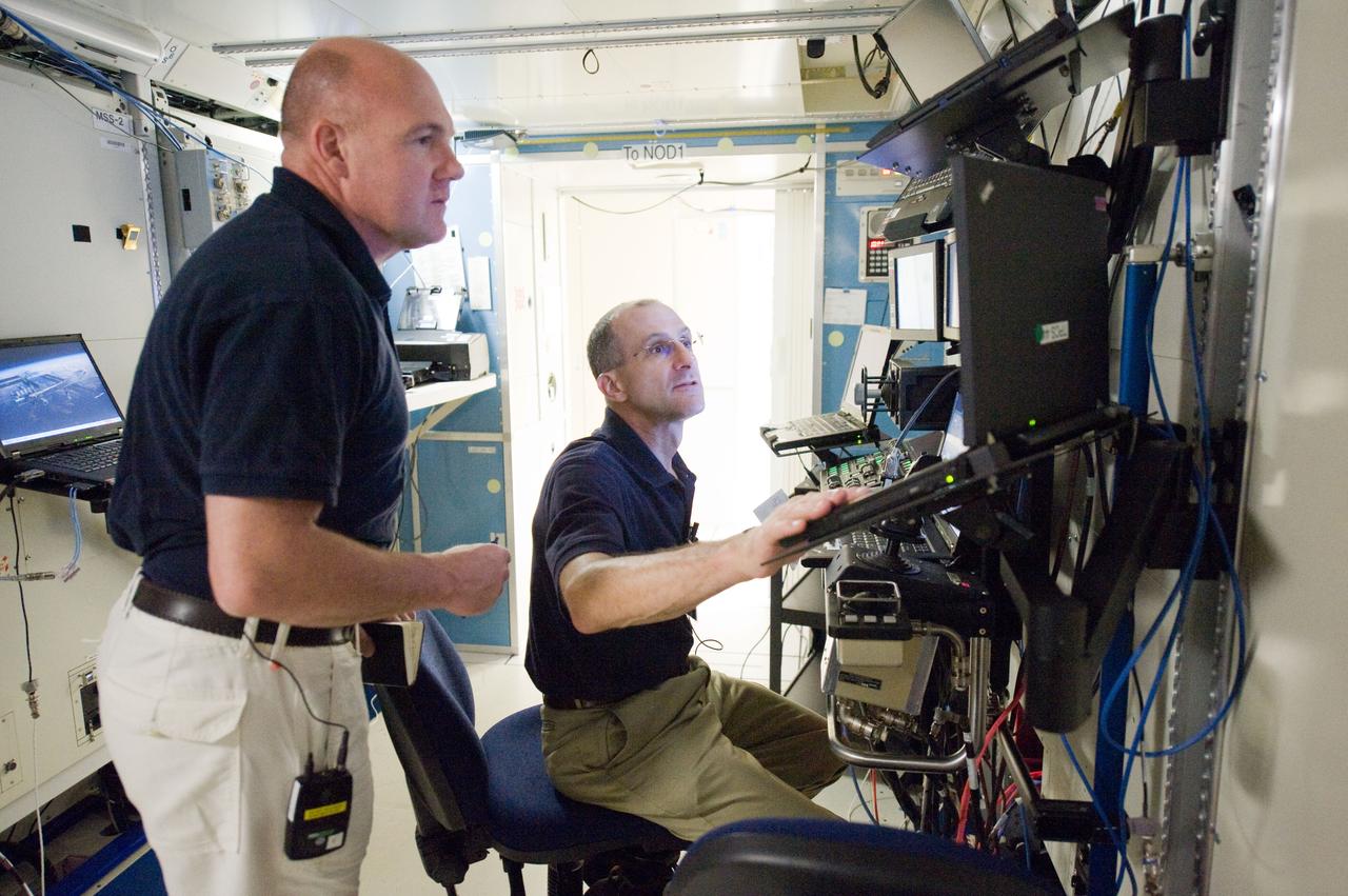
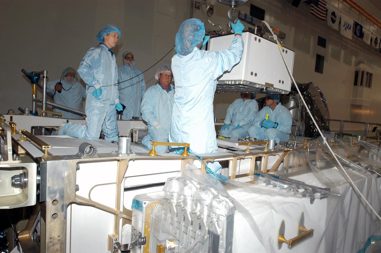
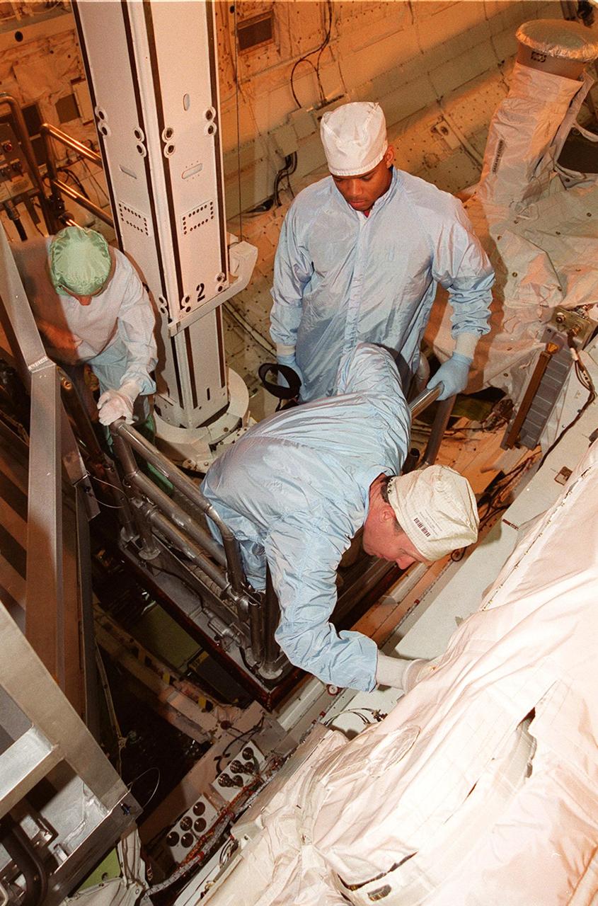
PHOTO DATE: 22 June 2011 LOCATION: Bldg. 5, Space Station Training Facility. SUBJECT: Expedition 29/30 crew training during Electrical Power System Major Case training event. Astronauts Dan Burbank, Don Pettit and Andre Kuipers working together in mockup. PHOTOGRAPHER: Mark Sowa
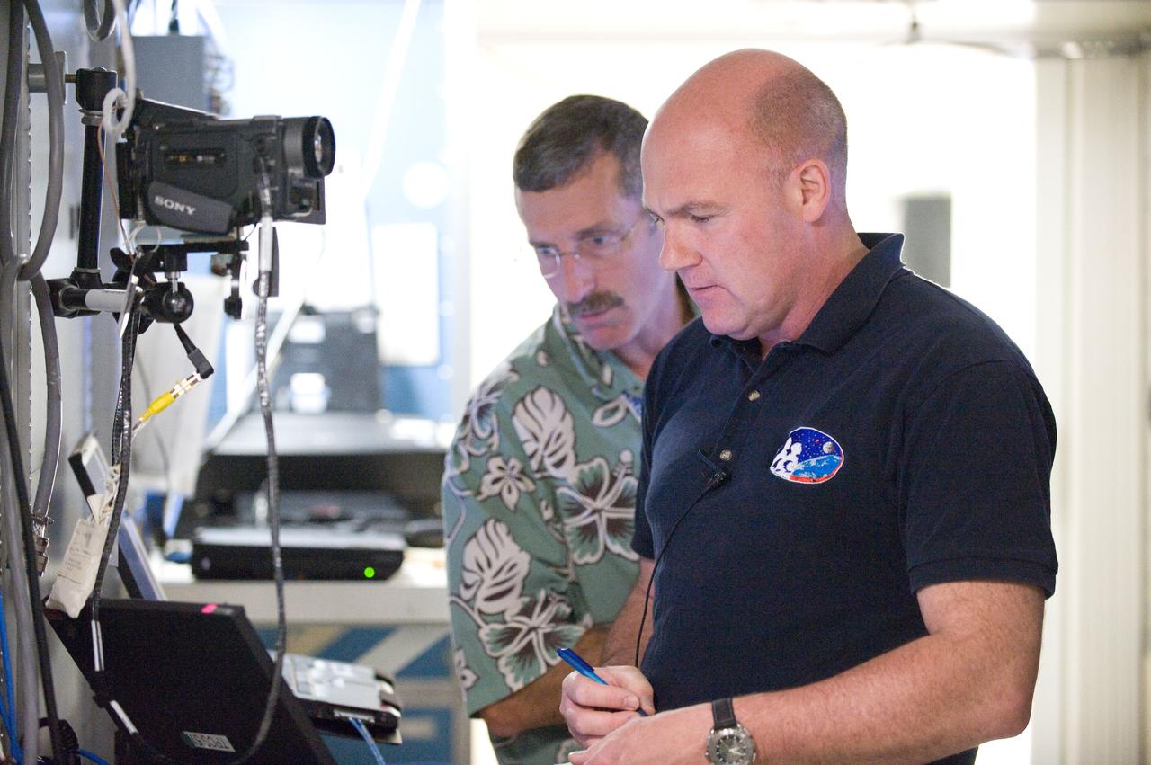
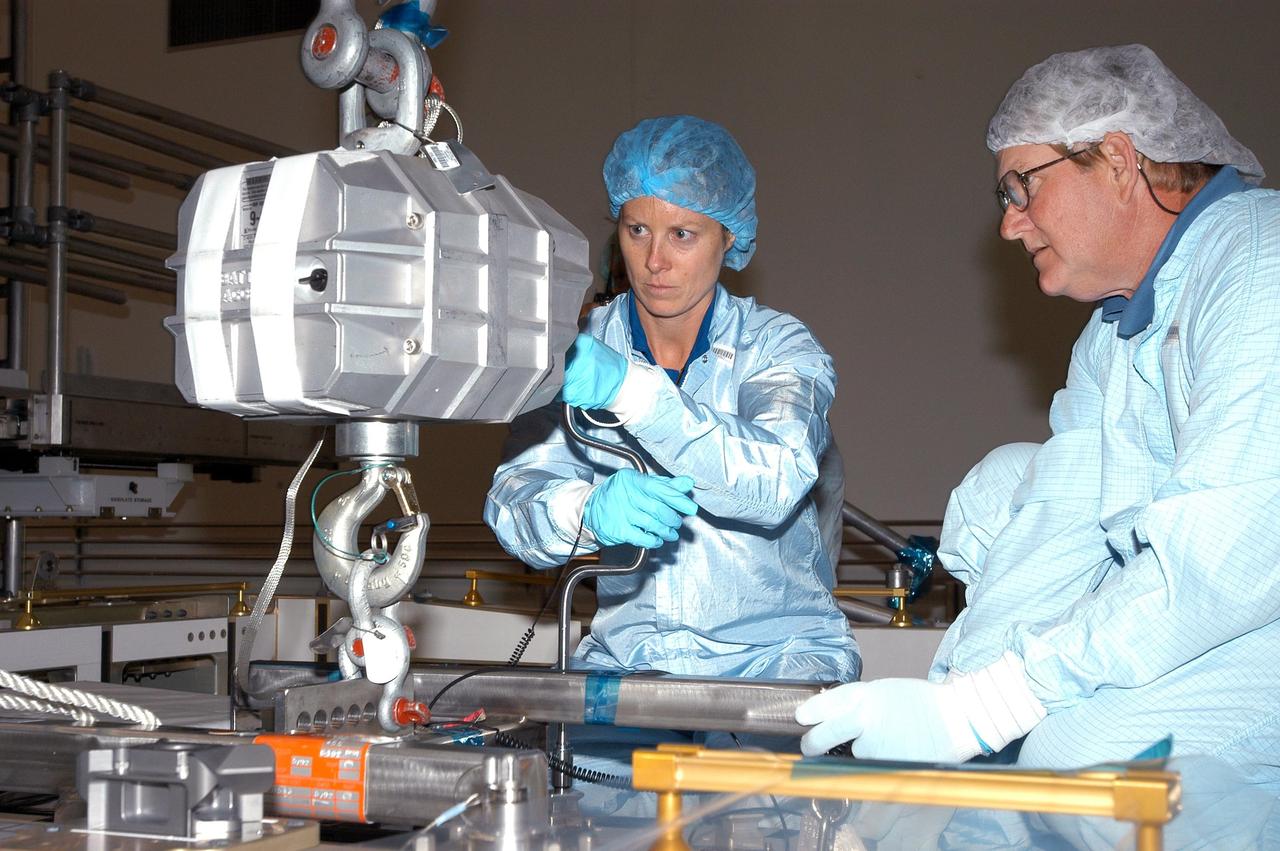
PHOTO DATE: 22 June 2011 LOCATION: Bldg. 5, Space Station Training Facility. SUBJECT: Expedition 29/30 crew training during Electrical Power System Major Case training event. Astronauts Dan Burbank, Don Pettit and Andre Kuipers working together in mockup. PHOTOGRAPHER: Mark Sowa
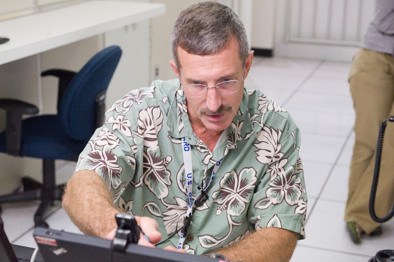
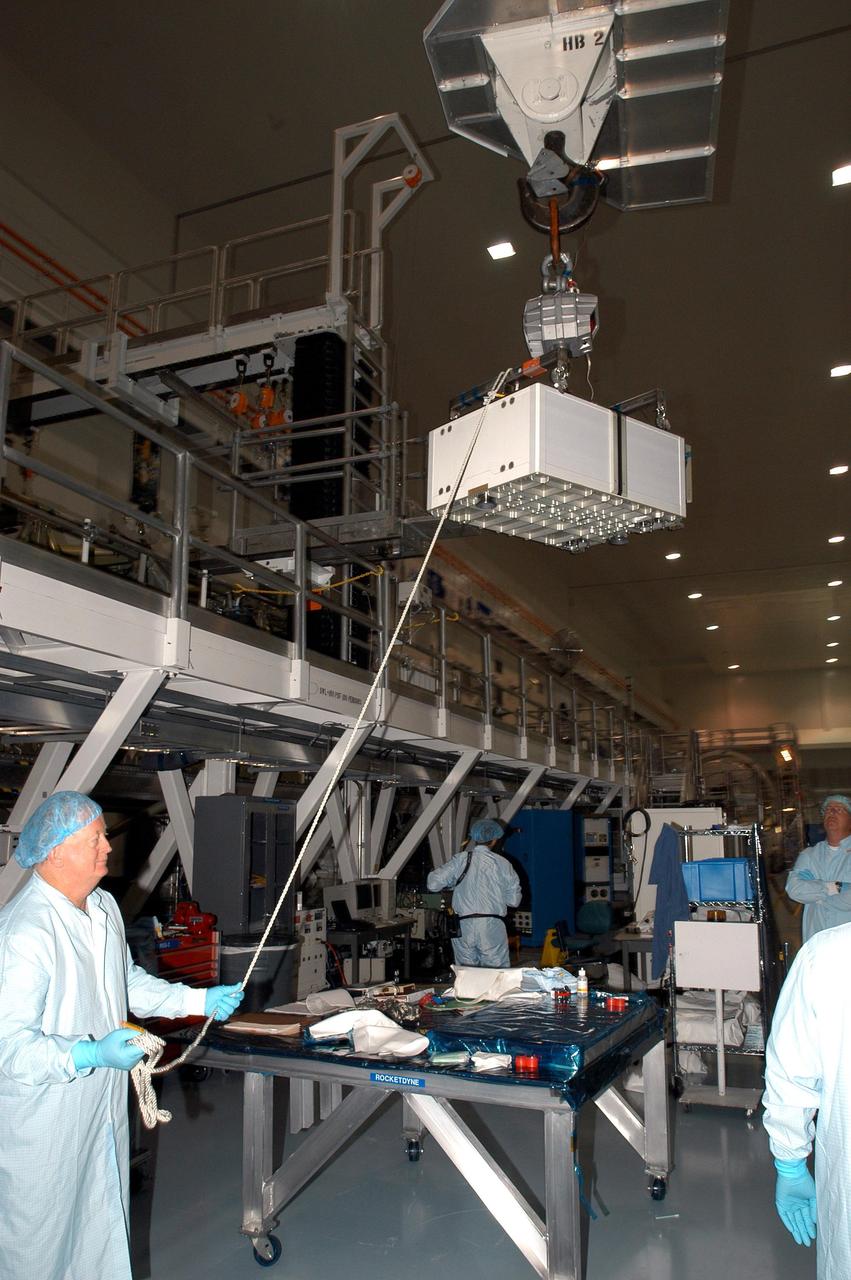
PHOTO DATE: 22 June 2011 LOCATION: Bldg. 5, Space Station Training Facility. SUBJECT: Expedition 29/30 crew training during Electrical Power System Major Case training event. Astronauts Dan Burbank, Don Pettit and Andre Kuipers working together in mockup. PHOTOGRAPHER: Mark Sowa
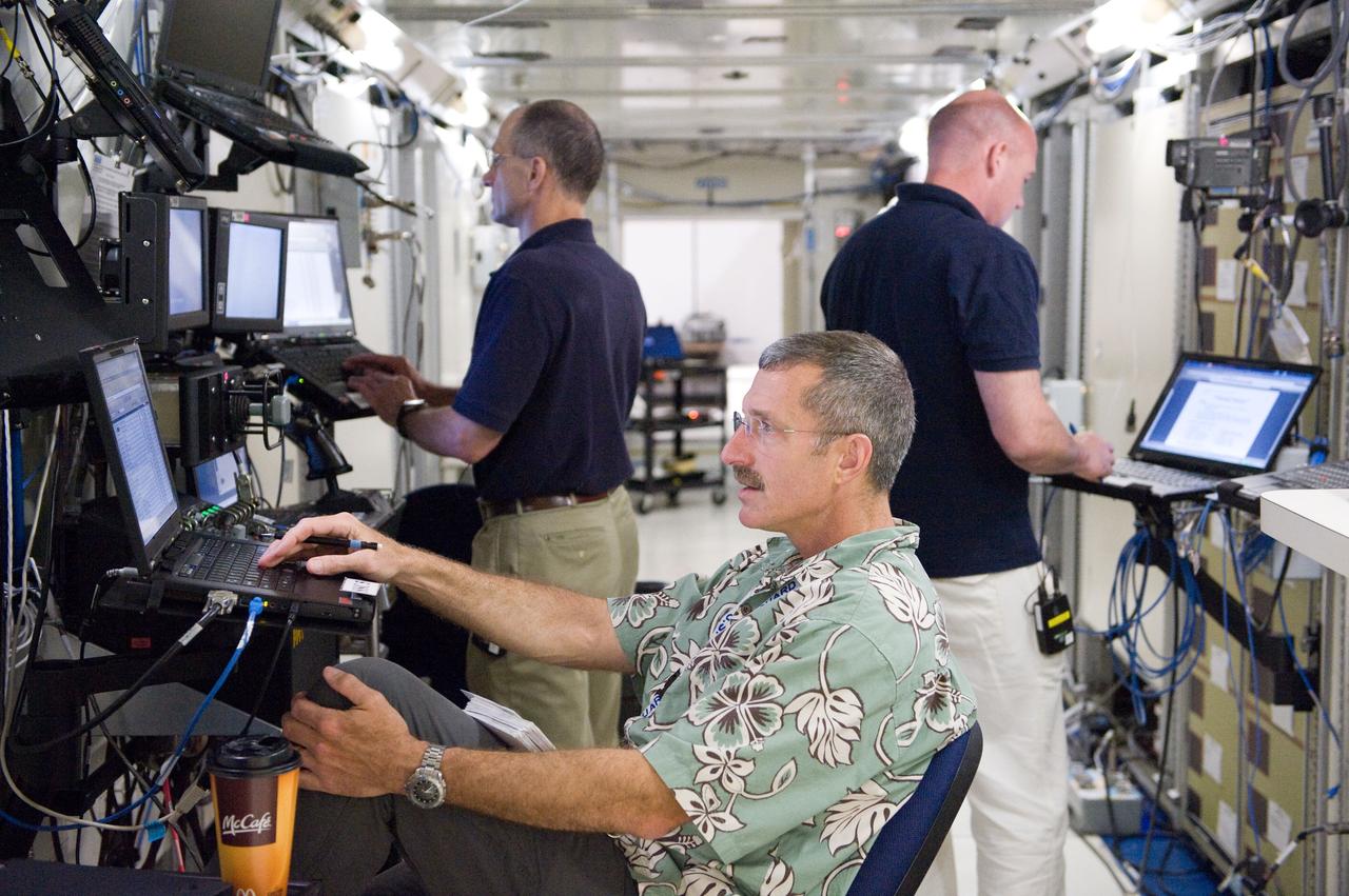
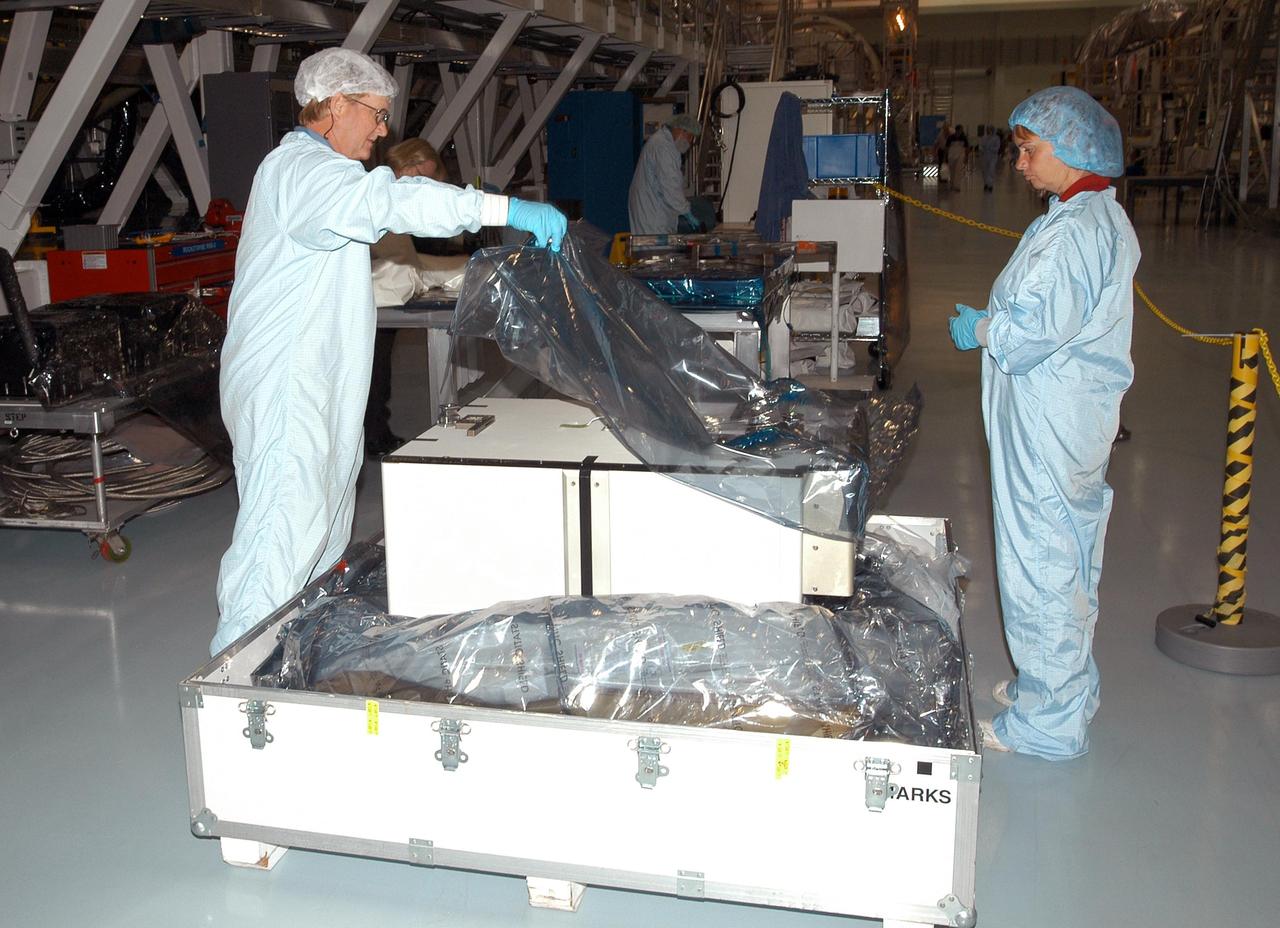
PHOTO DATE: 22 June 2011 LOCATION: Bldg. 5, Space Station Training Facility. SUBJECT: Expedition 29/30 crew training during Electrical Power System Major Case training event. Astronauts Dan Burbank, Don Pettit and Andre Kuipers working together in mockup. PHOTOGRAPHER: Mark Sowa
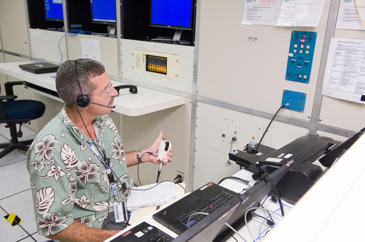
PHOTO DATE: 22 June 2011 LOCATION: Bldg. 5, Space Station Training Facility. SUBJECT: Expedition 29/30 crew training during Electrical Power System Major Case training event. Astronauts Dan Burbank, Don Pettit and Andre Kuipers working together in mockup. PHOTOGRAPHER: Mark Sowa
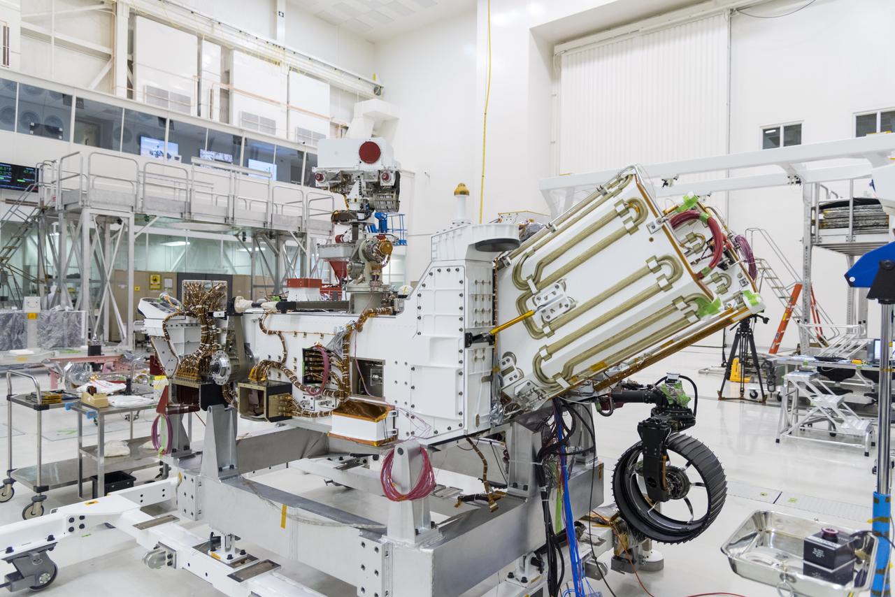
The electricity needed to operate NASA's Mars 2020 rover is provided by a power system called a Multi-Mission Radioisotope Thermoelectric Generator, or MMRTG. The MMRTG will be inserted into the aft end of the rover between the panels with gold tubing visible at the rear, which are called heat exchangers. Essentially a nuclear battery, an MMRTG uses the heat from the natural radioactive decay of plutonium-238 to generate about 110 watts of electricity at the start of a mission. Besides generating useful electrical power, the MMRTG produces heat. Some of this heat can be used to maintain the rover's systems at the proper operating temperatures in the frigid cold of space and on the surface of Mars. Some of it is rejected into space via the rover's Heat Rejection System. The gold-colored tubing on the heat exchangers form part of the cooling loops of that system. The tubes carry a fluid coolant called Trichlorofluoromethane (CFC-11) that helps dissipate the excess heat. The same tubes are used to pipe some of the heat back into the belly of the rover. MMRTGs are provided to NASA for civil space applications by the U.S. Department of Energy (DOE). The radioisotope fuel is inserted into the MMRTG at the DOE's Idaho National Laboratory before the MMRTG is shipped to the launch site. Electrically heated versions of the MMRTG are used at JPL to verify and practice integration of the power system with the rover. https://photojournal.jpl.nasa.gov/catalog/PIA23305
The electricity for NASA's Mars 2020 rover is provided by a power system called a Multi-Mission Radioisotope Thermoelectric Generator, or MMRTG. Essentially a nuclear battery, an MMRTG uses the heat from the natural radioactive decay of plutonium-238 to generate about 110 watts of electricity at the start of a mission. Besides generating electrical power, the MMRTG produces heat. Some of this heat can be used to maintain the rover's systems at the proper operating temperatures in the frigid cold of space and on the surface of Mars. This device, seen here before fueling and testing at the U.S. Department of Energy's Idaho National Laboratory, has "fins" that radiate excess heat. MMRTGs are provided to NASA for civil space applications by the U.S. Department of Energy (DOE). The radioisotope fuel is inserted into the MMRTG at the DOE's Idaho National Laboratory before the MMRTG is shipped to the launch site. Electrically heated versions of the MMRTG are used at JPL to verify and practice integration of the power system with the rover. https://photojournal.jpl.nasa.gov/catalog/PIA23306
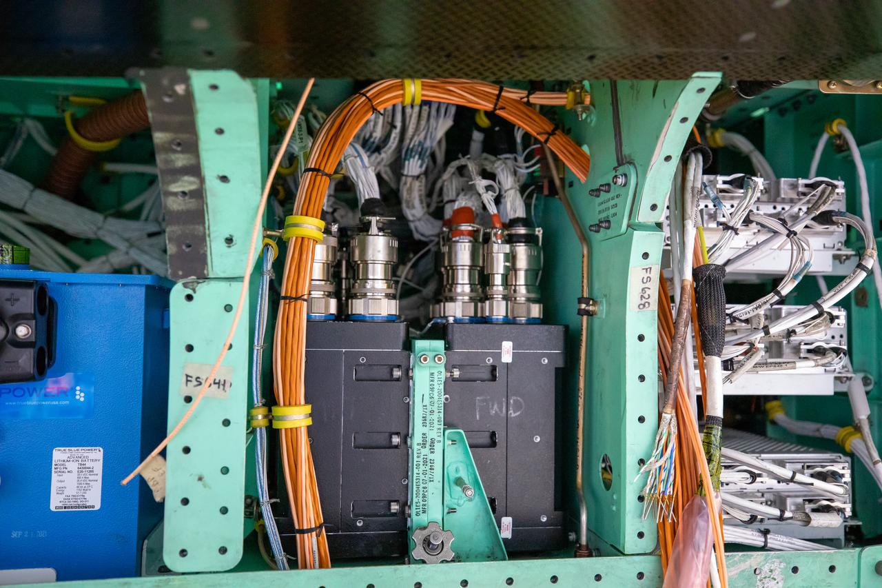
This is a closeup view of the inner workings of the X-59 aircraft. Visible are one the plane’s three lithium-ion batteries (blue box), electrical power system and other wiring components including the vehicle management systems computers (two black boxes) and the white wirings which assist in providing the power that is needed for the aircraft to function in flight. All of these components are essential to maintaining and monitoring the X-59 once it takes to the skies. The X-59 is the centerpiece of the Quesst mission which plans to help enable commercial supersonic air travel over land.
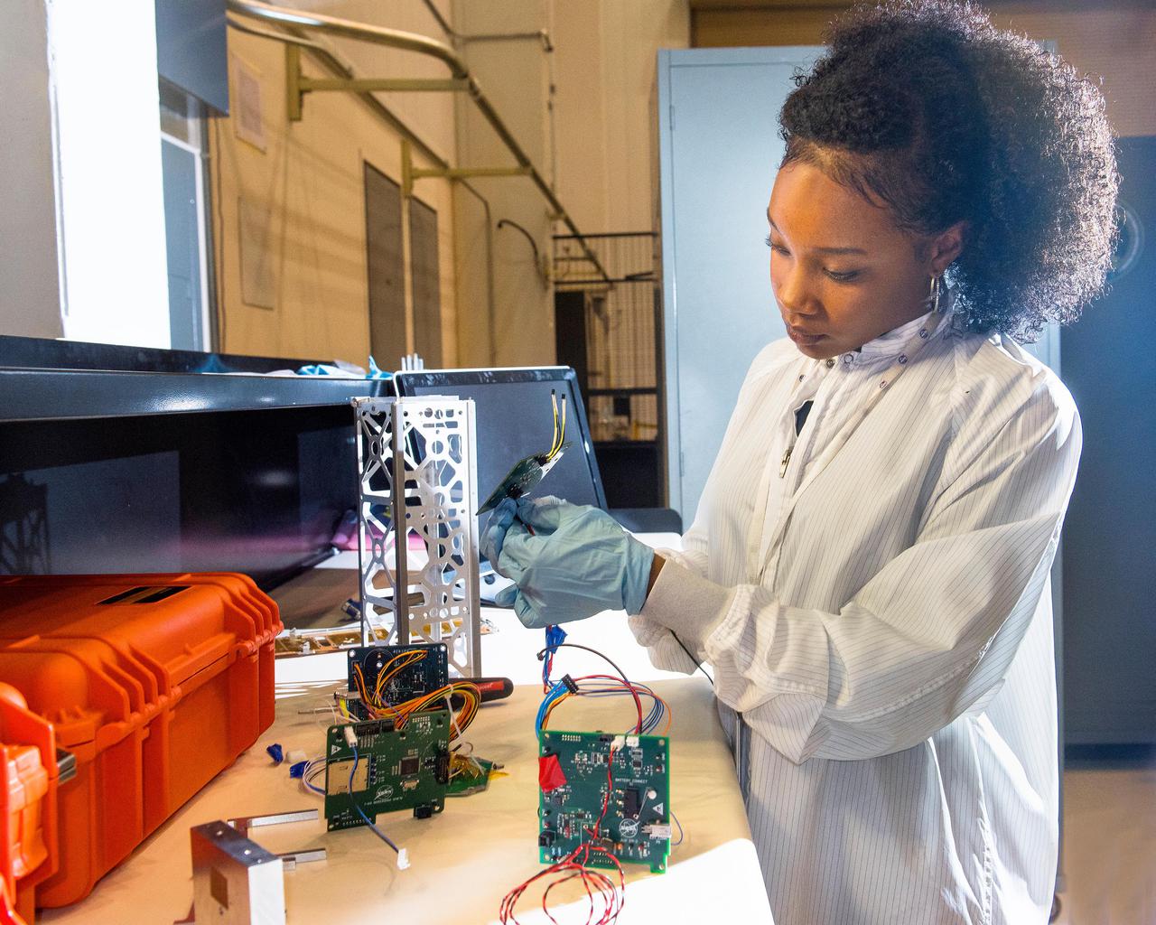
Advanced eLectrical Bus (ALBus) CubeSat: From Build to Flight A new CubeSat, launched Sunday, December 16, will test high power electric systems and the use of unique shape memory alloy (SMA) components for the first time. CubeSats are very small, lightweight satellites, about the size of a loaf of bread, and typically operate within a power range of 5-20 watts. Lower power systems are typically used in CubeSats because of size and weight limits, while higher power systems and components cause excessive heat. Completely designed and led by a team of 12 early career scientists and engineers at NASA’s Glenn Research Center in Cleveland, the Advanced Electrical Bus, or ALBus, will be the first CubeSat to demonstrate power management and distribution of a 100-watt electrical system. The CubeSat will also employ a custom-built SMA release mechanism and hinges to deploy solar arrays and conduct electricity.
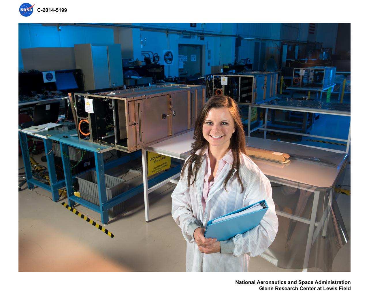
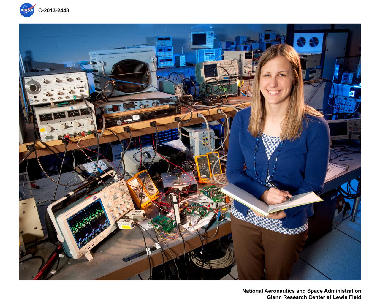
Environmental Portrait of an Electrical Power Systems Engineer

This is the crew insignia for STS-97 which delivered, assembled, and activated the U.S. electrical power system onboard the International Space Station (ISS). The electrical power system, which is built into a 47-foot integrated truss structure known as P6, consists of solar arrays, radiators, batteries, and electronics. P6 was prepared for subsequent deployments of larger solar arrays and radiator, a critical step in the activation of the electrical power system that will eventually provide the power necessary for the first ISS crews to live and work in the U.S. segment. The crew patch depicts the space shuttle docked to the ISS in low Earth orbit after the activation of the P6 electrical power system. Gold and silver were used to highlight the portion of the ISS that were installed by the STS-97 crew. The sun, central to the design, is the source of energy for the ISS. The crew member names surround the outer border of the patch.
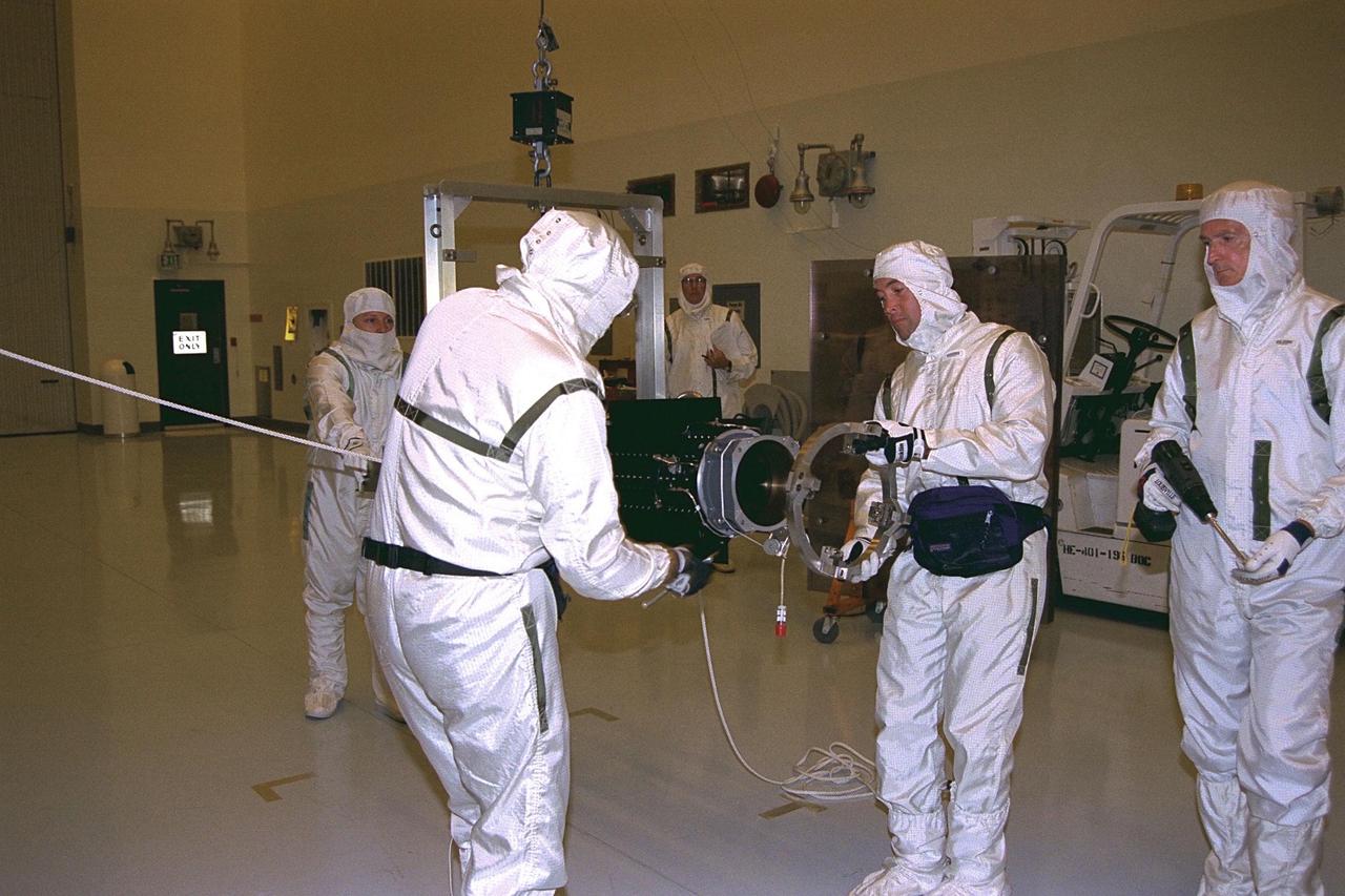
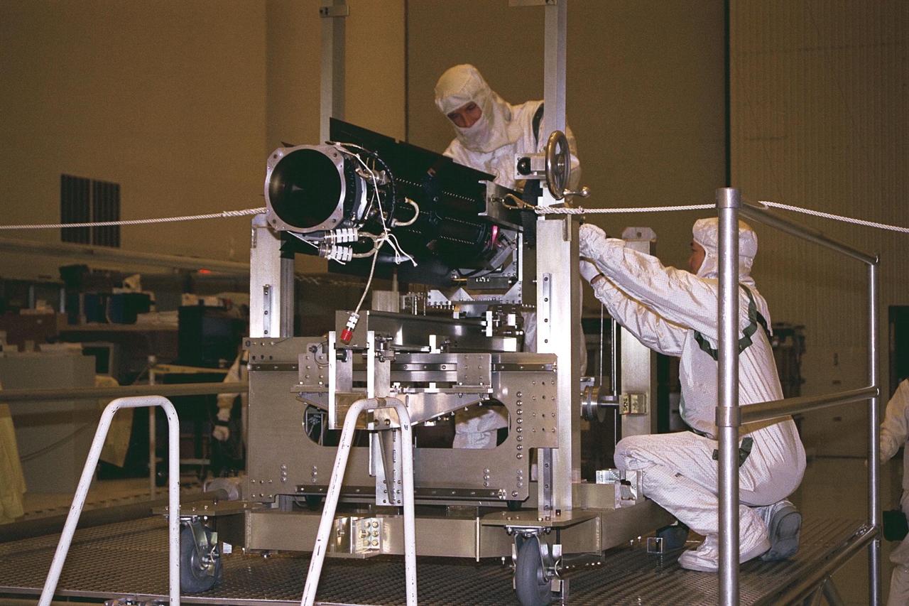
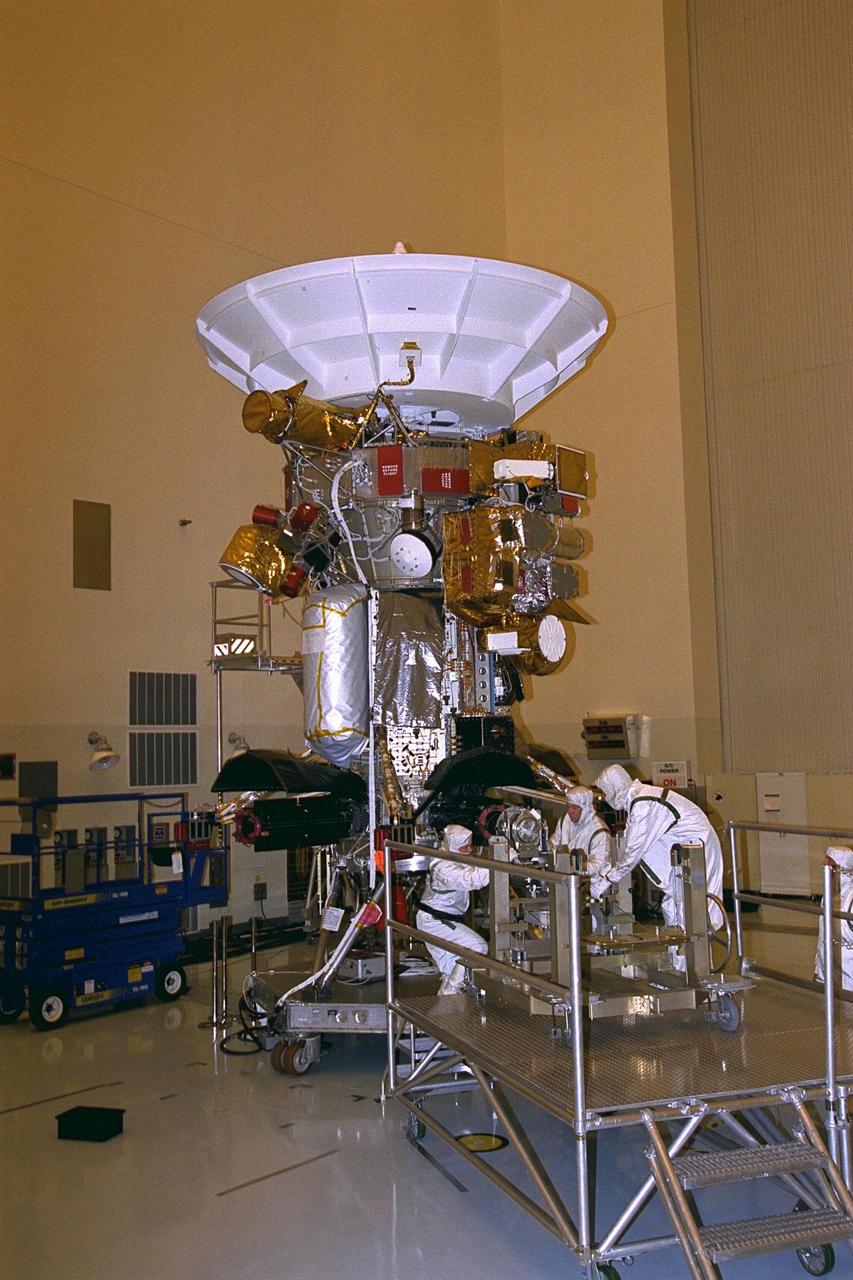
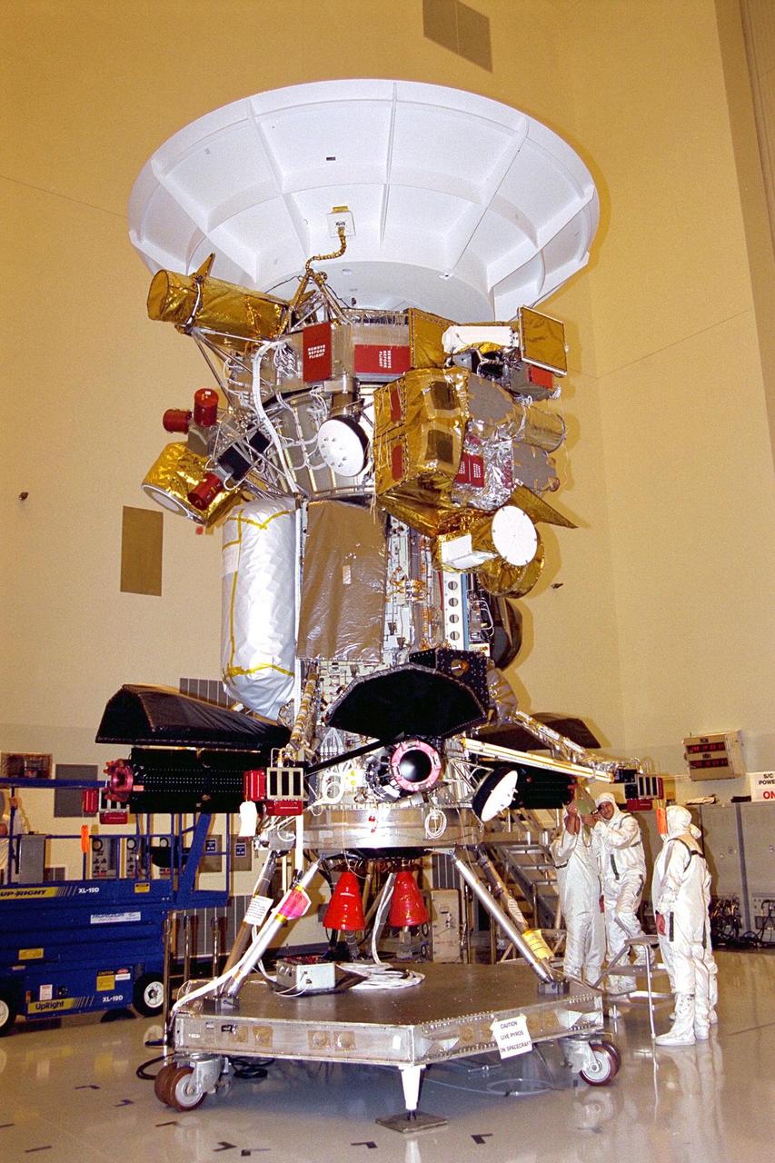
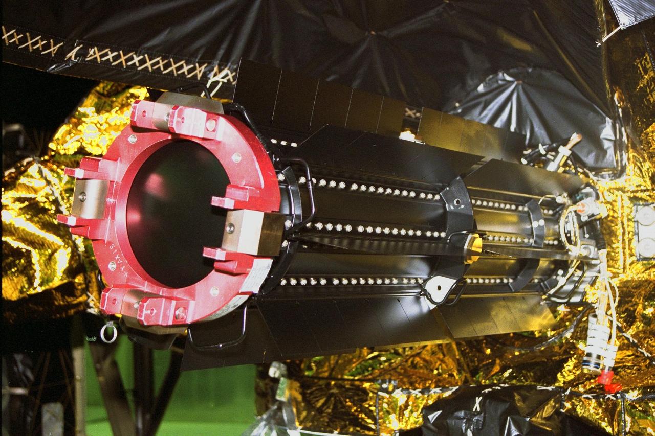
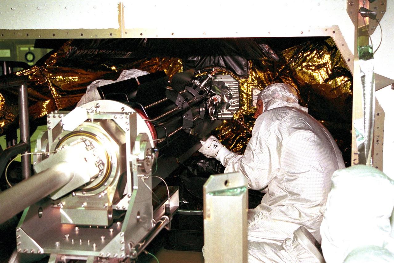
Workers in the Payload Hazardous Servicing Facility remove the storage collar from a radioisotope thermoelectric generator (RTG) in preparation for installation on the Cassini spacecraft. Cassini will be outfitted with three RTGs. The power units are undergoing mechanical and electrical verification tests in the PHSF. The RTGs will provide electrical power to Cassini on its 6.7-year trip to the Saturnian system and during its four-year mission at Saturn. RTGs use heat from the natural decay of plutonium to generate electric power. The generators enable spacecraft to operate at great distances from the Sun where solar power systems are not feasible. The Cassini mission is targeted for an Oct. 6 launch aboard a Titan IVB/Centaur expendable launch vehicle
Environmental Portrait, Electrical Power Systems Employee, hardware for the High Power 300-Volt Power Processing Unit (PPU). The Printed Circuit Boards (PCBs) are the Discharge Module Inverter and the Pulse Width Modulation (PWM) Controller
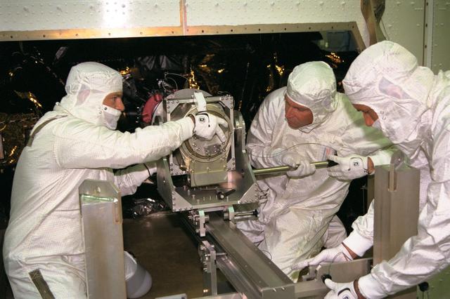
Jet Propulsion Research Lab (JPL) workers use a borescope to verify the pressure relief device bellow's integrity on a radioisotope thermoelectric generator (RTG) that has been installed on the Cassini spacecraft in the Payload Hazardous Servicing Facility. The activity is part of the mechanical and electrical verification testing of RTGs during prelaunch processing. RTGs use heat from the natural decay of plutonium to generate electrical power. The three RTGs on Cassini will enable the spacecraft to operate far from the Sun where solar power systems are not feasible. They will provide electrical power to Cassini on it seven year trip to the Saturnian system and during its four year mission at Saturn.
Jet Propulsion Research Lab (JPL) workers use a borescope to verify the pressure relief device bellow's integrity on a radioisotope thermoelectric generator (RTG) that has been installed on the Cassini spacecraft in the Payload Hazardous Servicing Facility. The activity is part of the mechanical and electrical verification testing of RTGs during prelaunch processing. RTGs use heat from the natural decay of plutonium to generate electrical power. The three RTGs on Cassini will enable the spacecraft to operate far from the Sun where solar power systems are not feasible. They will provide electrical power to Cassini on it seven year trip to the Saturnian system and during its four year mission at Saturn.
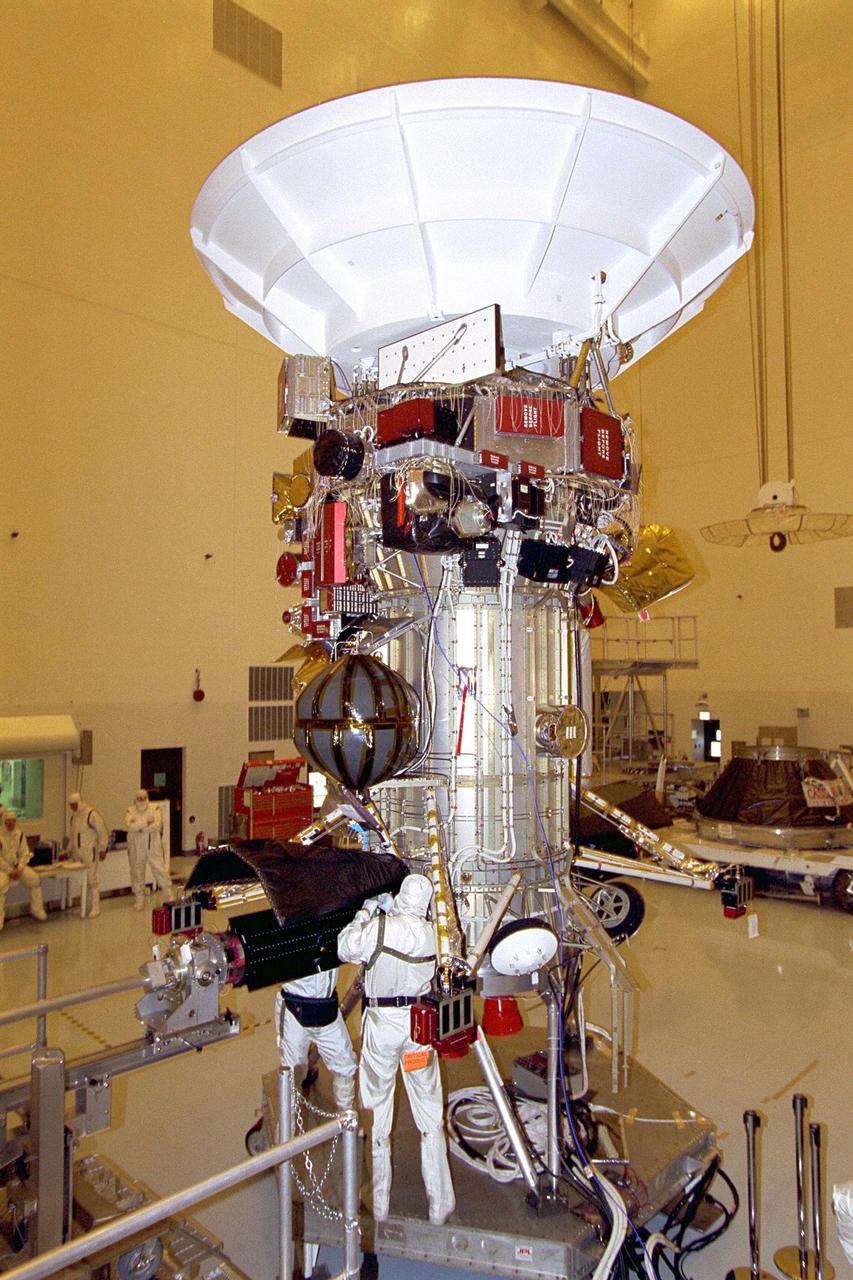
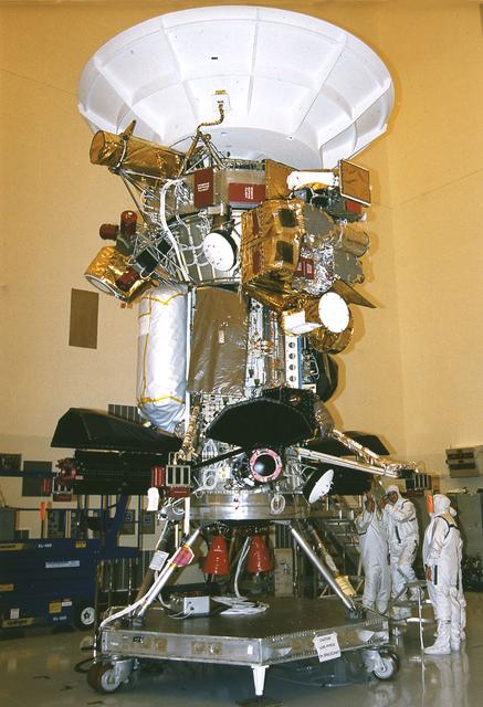
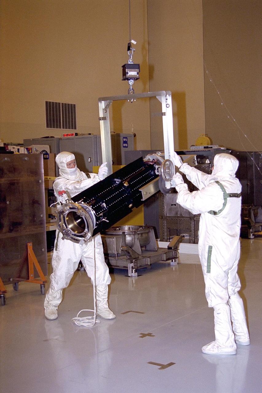
Jet Propulsion Laboratory (JPL) workers Dan Maynard and John Shuping prepare to install a radioisotope thermoelectric generator (RTG) on the Cassini spacecraft in the Payload Hazardous Servicing Facility (PHSF). The three RTGs which will provide electrical power to Cassini on its mission to the Saturnian system are undergoing mechanical and electrical verification testing in the PHSF. RTGs use heat from the natural decay of plutonium to generate electric power. The generators enable spacecraft to operate far from the Sun where solar power systems are not feasible. The Cassini mission is scheduled for an Oct. 6 launch aboard a Titan IVB/Centaur expendable launch vehicle. Cassini is built and managed for NASA by JPL
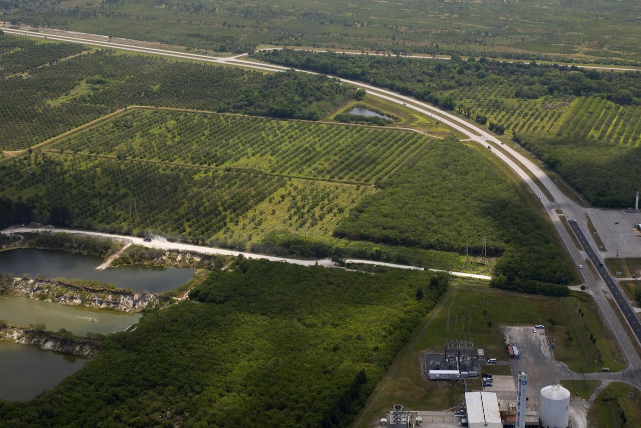
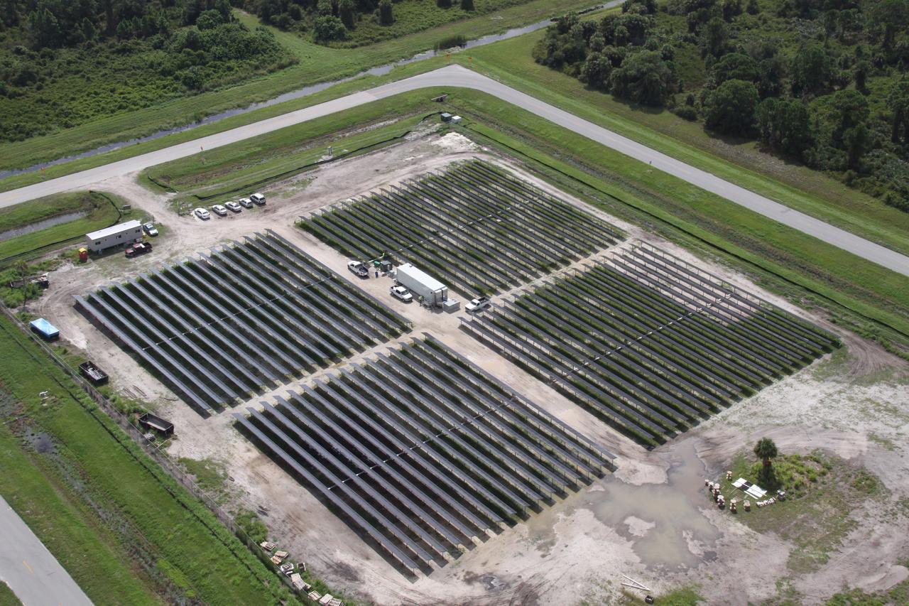
CAPE CANAVERAL, Fla. – This photo shows the area within NASA's Kennedy Space Center where a solar photovoltaic power generation system will be built as the result of an agreement between NASA and Florida Power & Light. The agreement is part of a new initiative that will cut reliance on fossil fuels and improve the environment by reducing greenhouse gas emissions. The major facility will produce an estimated 10 megawatts of electrical power, which can serve roughly 3,000 homes. A separate one-megawatt solar power facility will support the electrical needs of the center.
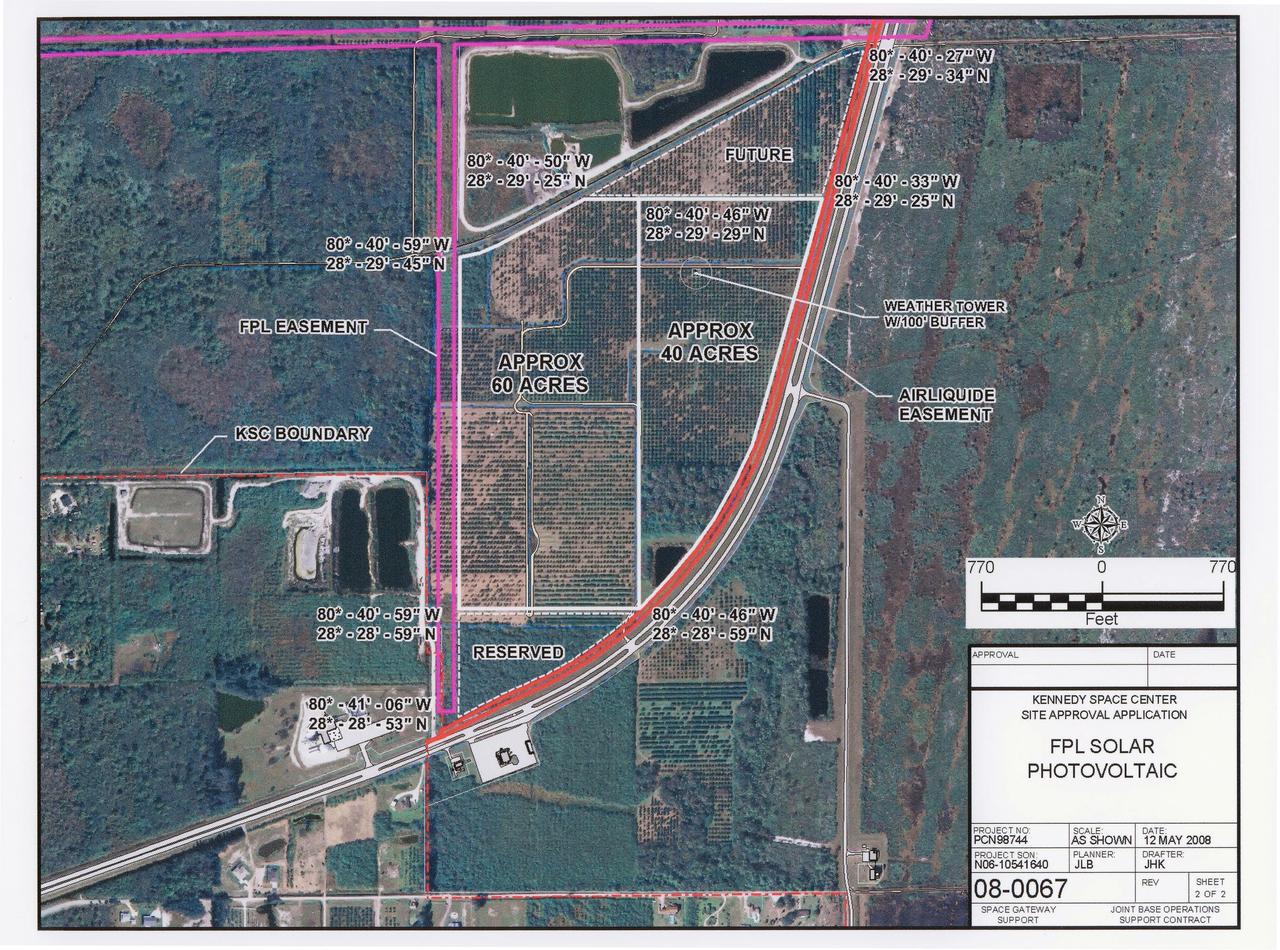
CAPE CANAVERAL, Fla. – This map shows the area within NASA's Kennedy Space Center where a solar photovoltaic power generation system will be built as the result of an agreement between NASA and Florida Power & Light. The agreement is part of a new initiative that will cut reliance on fossil fuels and improve the environment by reducing greenhouse gas emissions. The major facility will produce an estimated 10 megawatts of electrical power, which can serve roughly 3,000 homes. A separate one-megawatt solar power facility will support the electrical needs of the center.
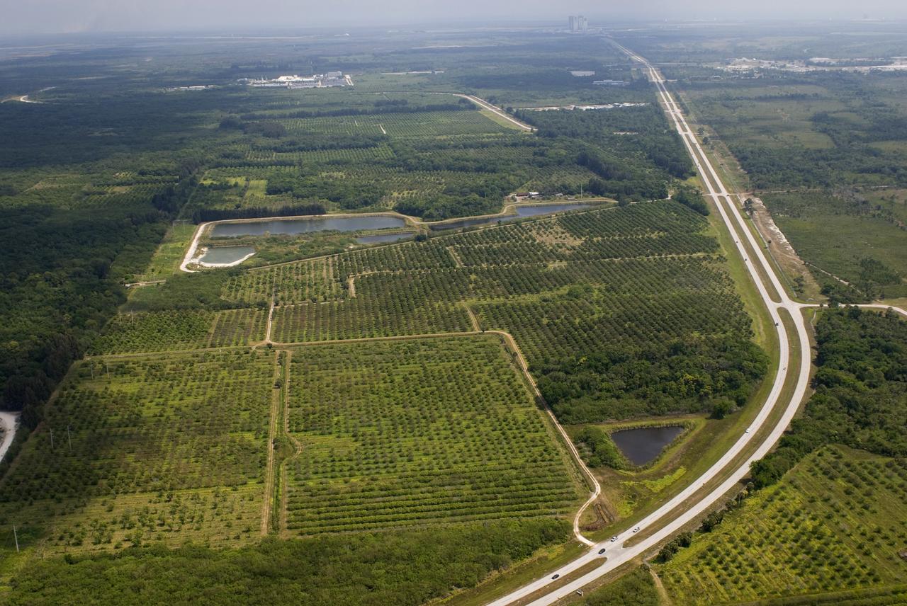
CAPE CANAVERAL, Fla. – This photo shows the area within NASA's Kennedy Space Center where a solar photovoltaic power generation system will be built as the result of an agreement between NASA and Florida Power & Light. The agreement is part of a new initiative that will cut reliance on fossil fuels and improve the environment by reducing greenhouse gas emissions. The major facility will produce an estimated 10 megawatts of electrical power, which can serve roughly 3,000 homes. A separate one-megawatt solar power facility will support the electrical needs of the center.
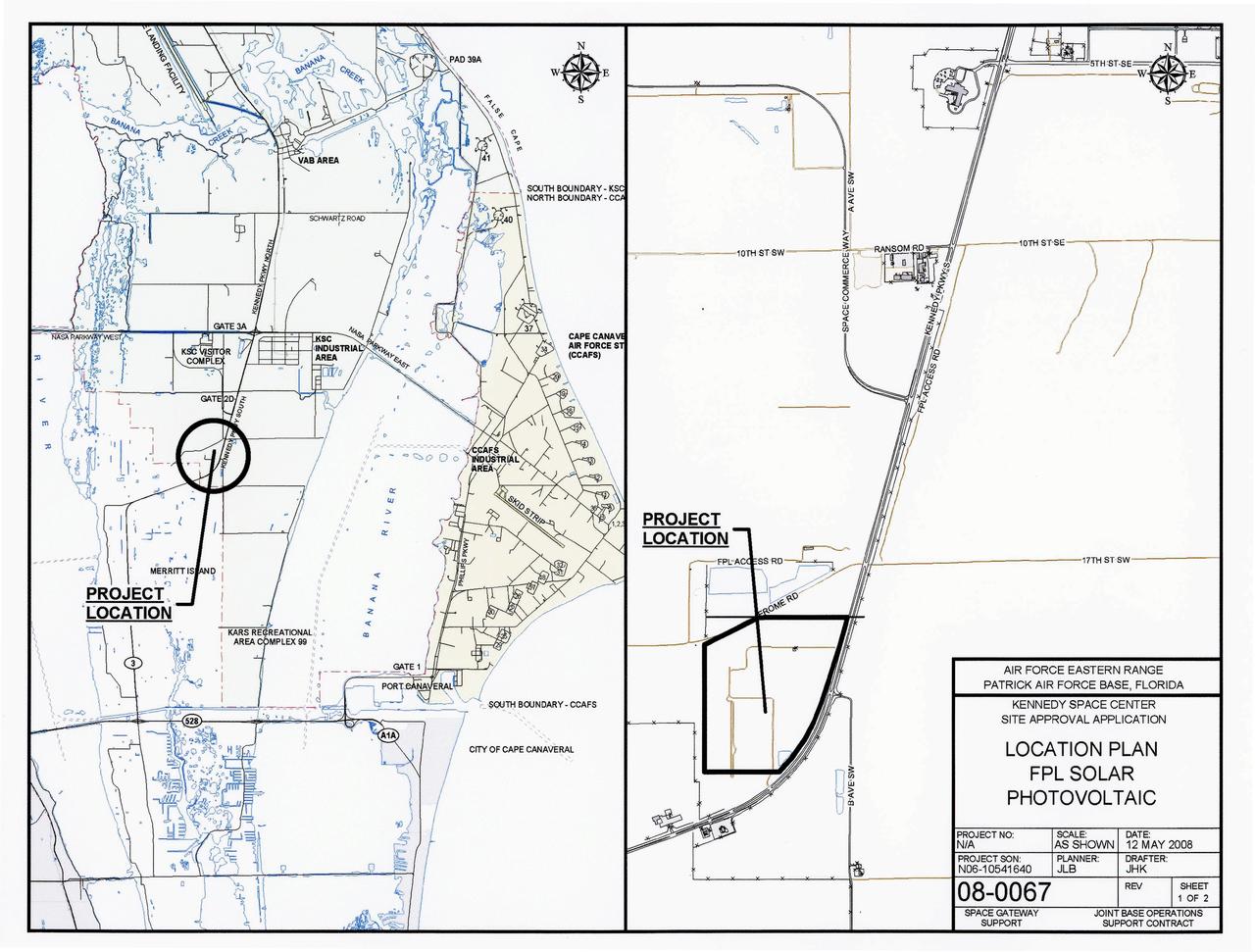
CAPE CANAVERAL, Fla. – This map shows the two sites within NASA's Kennedy Space Center where a solar photovoltaic power generation system will be built as the result of an agreement between NASA and Florida Power & Light. The agreement is part of a new initiative that will cut reliance on fossil fuels and improve the environment by reducing greenhouse gas emissions. The major facility will produce an estimated 10 megawatts of electrical power, which can serve roughly 3,000 homes. A separate one-megawatt solar power facility will support the electrical needs of the center.
CAPE CANAVERAL, Fla. – This map shows the two sites within NASA's Kennedy Space Center where a solar photovoltaic power generation system will be built as the result of an agreement between NASA and Florida Power & Light. The agreement is part of a new initiative that will cut reliance on fossil fuels and improve the environment by reducing greenhouse gas emissions. The major facility will produce an estimated 10 megawatts of electrical power, which can serve roughly 3,000 homes. A separate one-megawatt solar power facility will support the electrical needs of the center.

STS097-S-001 (January 2000) --- This is the crew insignia for STS-97, which will deliver, assemble, and activate the U.S. electrical power system on board the International Space Station (ISS). The electrical power system, which is built into a 47-foot integrated truss structure known as P6, consists of solar arrays, radiators, batteries, and electronics. P6 will be attached to the station using the shuttle's robotic arm in coordination with spacewalking crew members that will make the final connections. The spacewalkers will then prepare P6 for the subsequent deployments of the large solar arrays and radiator, which are critical steps in the activation of the electrical power system. The 120-foot solar arrays will provide the power necessary for the first ISS crews to live and work in the U.S. segment. The crew patch depicts the space shuttle docked to ISS in low Earth orbit after the activation of the P6 electrical power system. Gold and silver are used to highlight the portion of ISS that will be installed by the STS-97 crew. The Sun, central to the design, is the source of energy for ISS. The NASA insignia design for space shuttle flights is reserved for use by the astronauts and for other official use as the NASA Administrator may authorize. Public availability has been approved only in the forms of illustrations by the various news media. When and if there is any change in this policy, which is not anticipated, the change will be publicly announced. Photo credit: NASA
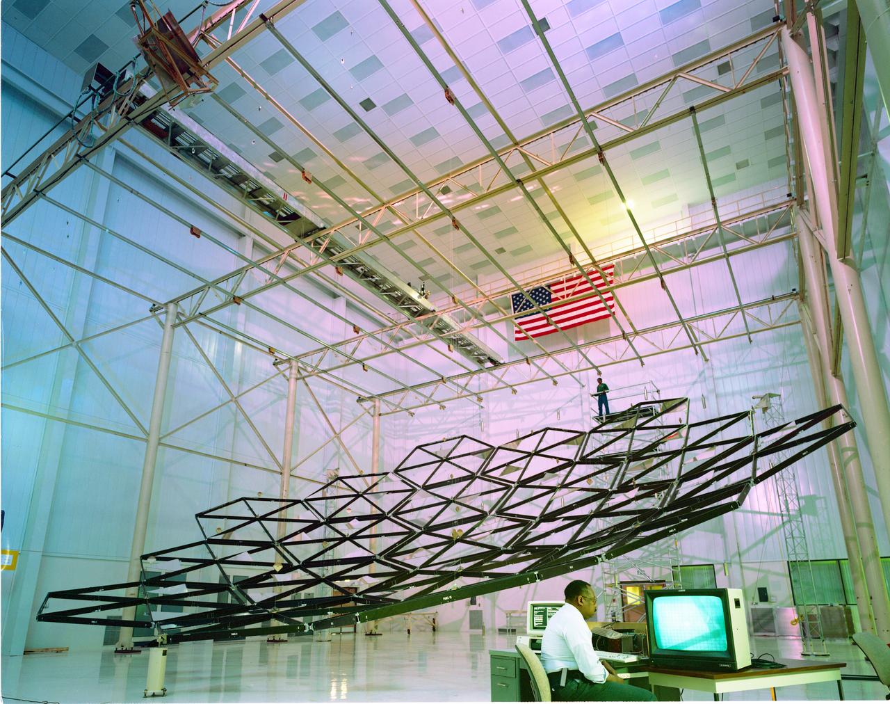
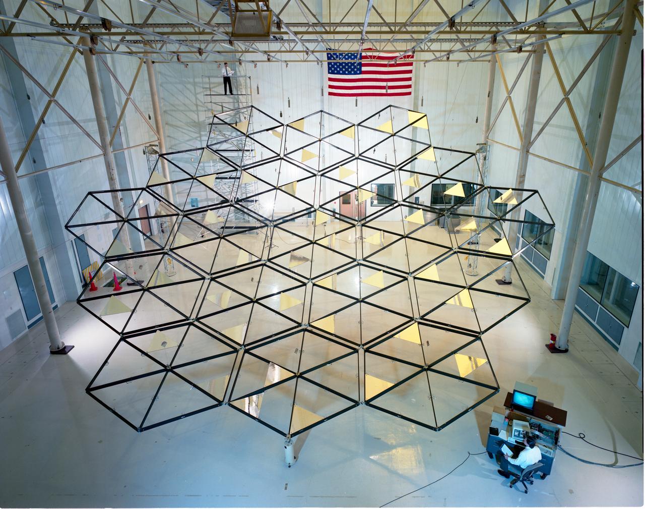
NASA’s Lewis Research Center conducted extensive research programs in the 1960s and 1970s to develop systems that provide electrical power in space. One system, the Brayton cycle engine, converted solar thermal energy into electrical power. This system operated on a closed-loop Brayton thermodynamic cycle. The Brayton system relied on this large mirror to collect radiation from the sun. The mirror concentrated the Sun's rays on a heat storage receiver which warmed the Brayton system’s working fluid, a helium-xenon gas mixture. The heated fluid powered the system’s generator which produced power. In the mid-1960s Lewis researchers constructed this 30-foot diameter prototype of a parabolic solar mirror for the Brayton cycle system. The mirror had to be rigid, impervious to micrometeorite strikes, and lightweight. This mirror was comprised of twelve 1-inch thick magnesium plate sections that were coated with aluminum. The mirror could be compactly broken into its sections for launch.
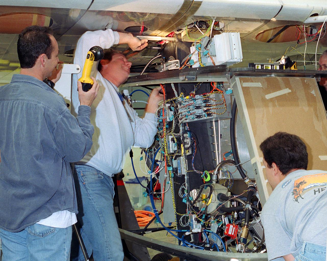
Aerovironment technicians carefully line up attachments as a fuel cell electrical system is installed on the Helios Prototype solar powered flying wing. The fuel cell system will power the aircraft at night during NASA-sponsored long-endurance demonstration flight in the summer of 2003.

Jet Propulsion Laboratory (JPL) worker Mary Reaves mates connectors on a radioisotope thermoelectric generator (RTG) to power up the Cassini spacecraft, while quality assurance engineer Peter Sorci looks on. The three RTGs which will be used on Cassini are undergoing mechanical and electrical verification testing in the Payload Hazardous Servicing Facility. The RTGs will provide electrical power to Cassini on its 6.7-year trip to the Saturnian system and during its four-year mission at Saturn. RTGs use heat from the natural decay of plutonium to generate electric power. The generators enable spacecraft to operate at great distances from the Sun where solar power systems are not feasible. The Cassini mission is targeted for an Oct. 6 launch aboard a Titan IVB/Centaur expendable launch vehicle. Cassini is built and managed by JPL

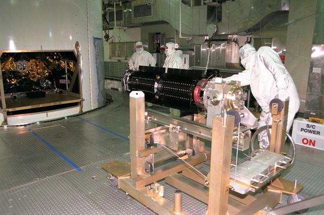
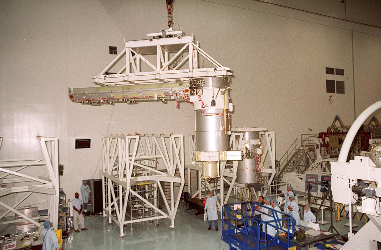
Jet Propulsion Laboratory (JPL) workers carefully roll into place a platform with a second radioisotope thermoelectric generator (RTG) for installation on the Cassini spacecraft. In background at left, the first of three RTGs already has been installed on Cassini. The RTGs will provide electrical power to Cassini on its 6.7-year trip to the Saturnian system and during its four-year mission at Saturn. The power units are undergoing mechanical and electrical verification testing in the Payload Hazardous Servicing Facility. RTGs use heat from the natural decay of plutonium to generate electric power. The generators enable spacecraft to operate far from the Sun where solar power systems are not feasible. The Cassini mission is scheduled for an Oct. 6 launch aboard a Titan IVB/Centaur expendable launch vehicle. Cassini is built and managed for NASA by JPL
Jet Propulsion Laboratory (JPL) employees Norm Schwartz, at left, and George Nakatsukasa transfer one of three radioisotope thermoelectric generators (RTGs) to be used on the Cassini spacecraft from the installation cart to a lift fixture in preparation for returning the power unit to storage. The three RTGs underwent mechanical and electrical verification testing in the Payload Hazardous Servicing Facility. The RTGs will provide electrical power to Cassini on its 6.7-year trip to the Saturnian system and during its four-year mission at Saturn. RTGs use heat from the natural decay of plutonium to generate electric power. The generators enable spacecraft to operate at great distances from the Sun where solar power systems are not feasible. The Cassini mission is targeted for an Oct. 6 launch aboard a Titan IVB/Centaur expendable launch vehicle. Cassini is built and managed by JPL
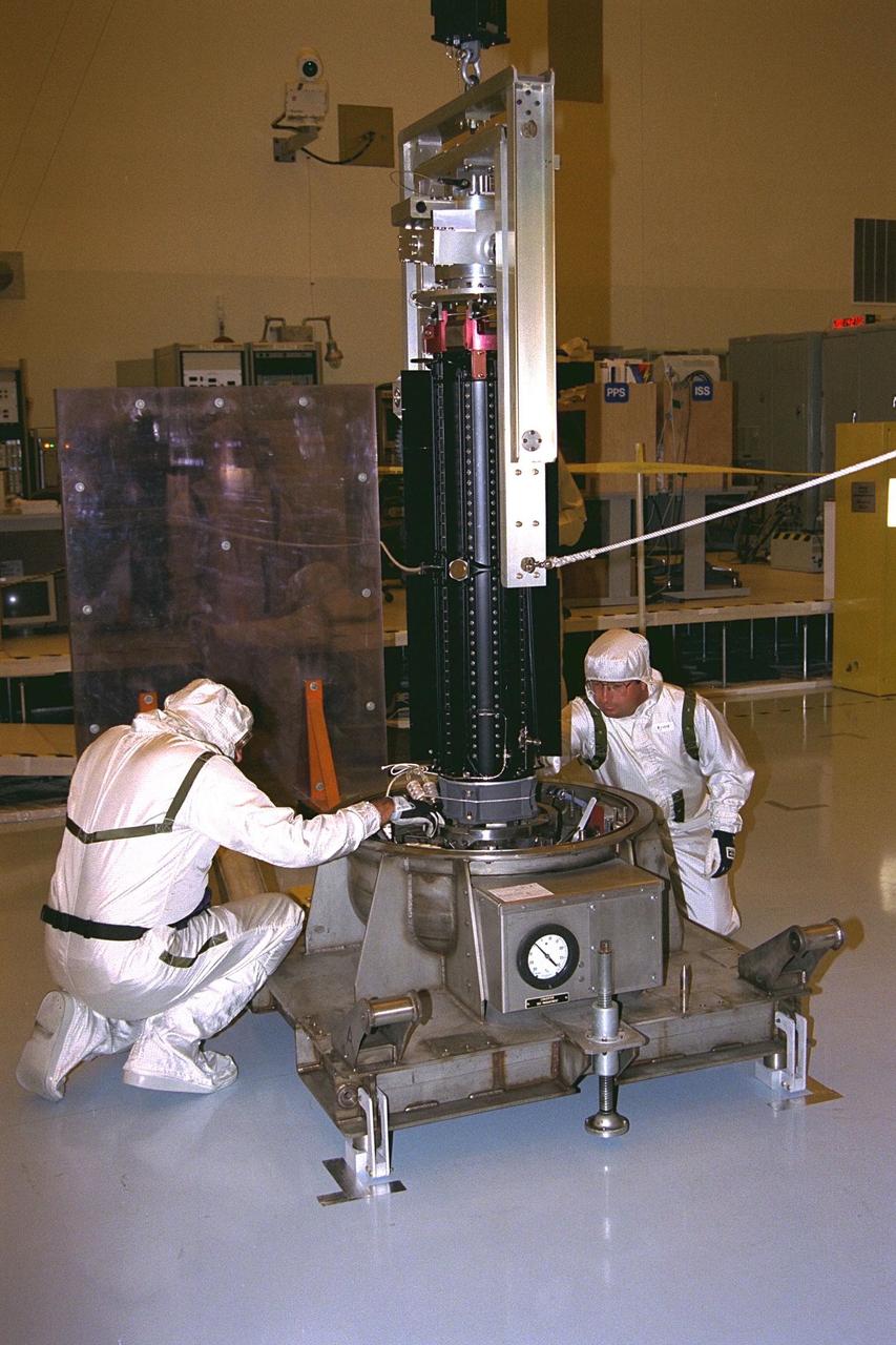
Jet Propulsion Laboratory (JPL) workers David Rice, at left, and Johnny Melendez rotate a radioisotope thermoelectric generator (RTG) to the horizontal position on a lift fixture in the Payload Hazardous Servicing Facility. The RTG is one of three generators which will provide electrical power for the Cassini spacecraft mission to the Saturnian system. The RTGs will be installed on the powered-up spacecraft for mechanical and electrical verification testing. RTGs use heat from the natural decay of plutonium to generate electric power. The generators enable spacecraft to operate far from the Sun where solar power systems are not feasible. The Cassini mission is scheduled for an Oct. 6 launch aboard a Titan IVB/Centaur expendable launch vehicle. Cassini is built and managed for NASA by JPL
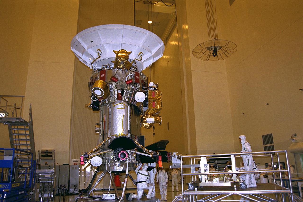
Jet Propulsion Laboratory (JPL) employees bolt a radioisotope thermoelectric generator (RTG) onto the Cassini spacecraft, at left, while other JPL workers, at right, operate the installation cart on a raised platform in the Payload Hazardous Servicing Facility (PHSF). Cassini will be outfitted with three RTGs. The power units are undergoing mechanical and electrical verification tests in the PHSF. The RTGs will provide electrical power to Cassini on its 6.7-year trip to the Saturnian system and during its four-year mission at Saturn. RTGs use heat from the natural decay of plutonium to generate electric power. The generators enable spacecraft to operate at great distances from the Sun where solar power systems are not feasible. The Cassini mission is targeted for an Oct. 6 launch aboard a Titan IVB/Centaur expendable launch vehicle. Cassini is built and managed by JPL
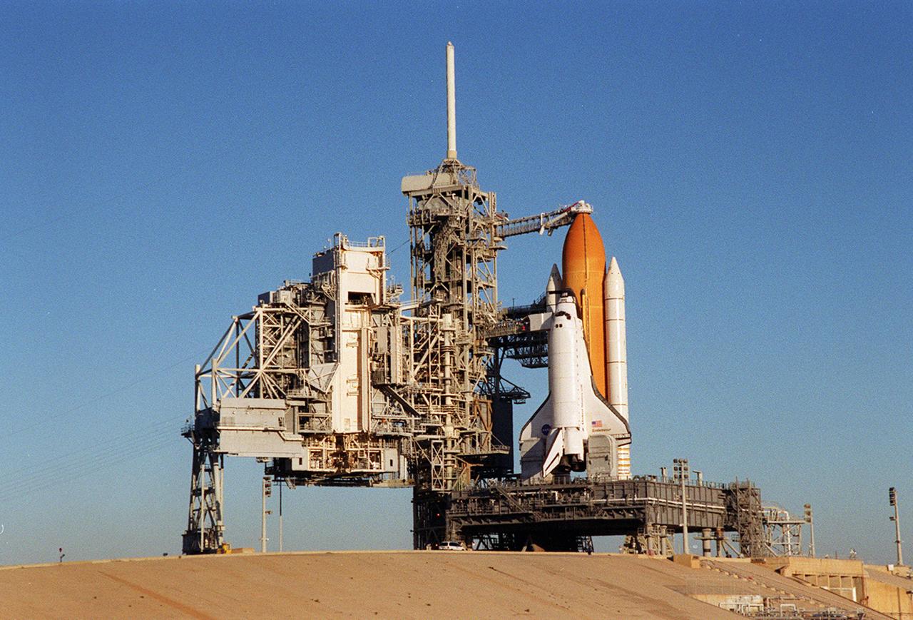
Back dropped by a cloudless blue sky, Space Shuttle Endeavor stands ready for launch after the rollback of the Rotating Service Structure, at left. The orbiter launched that night carrying the STS-97 crew of five. The STS-97 mission's primary objective was the delivery, assembly, and activation of the U.S. electrical power system onboard the International Space Station (ISS). The electrical power system, which is built into a 73-meter (240-foot) long solar array structure, consists of solar arrays, radiators, batteries, and electronics. The entire 15.4-metric ton (17-ton) package is called the P6 Integrated Truss Segment, and is the heaviest and largest element yet delivered to the station aboard a space shuttle. The electric system will eventually provide the power necessary for the first ISS crews to live and work in the U.S. segment.
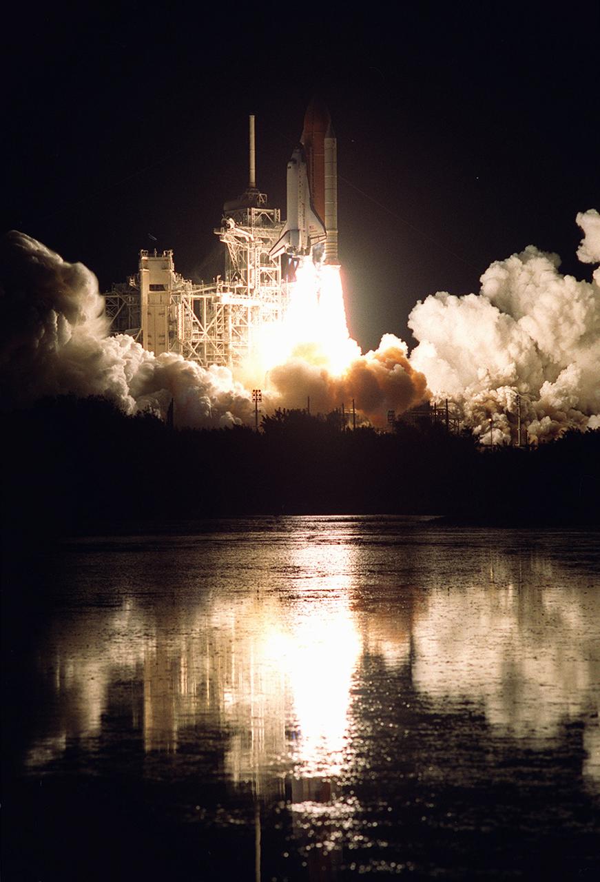
Nearby waters reflect the flames of the Space Shuttle Endeavor as she lifts off November 30, 2000, carrying the STS-97 crew of five. The STS-97 mission's primary objective was the delivery, assembly, and activation of the U.S. electrical power system onboard the International Space Station (ISS). The electrical power system, which is built into a 73-meter (240-foot) long solar array structure, consists of solar arrays, radiators, batteries, and electronics. The entire 15.4-metric ton (17-ton) package is called the P6 Integrated Truss Segment and is the heaviest and largest element yet delivered to the station aboard a space shuttle. The electrical system will eventually provide the power necessary for the first ISS crews to live and work in the U.S. segment.
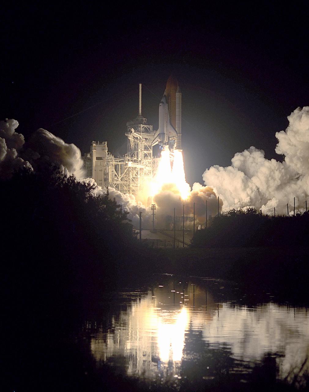
Nearby waters reflect the flames of the Space Shuttle Endeavor as she lifts off November 30, 2000 carrying the STS-97 crew of five. The STS-97 mission's primary objective was the delivery, assembly, and activation of the U.S. electrical power system onboard the International Space Station (ISS). The electrical power system, which is built into a 73-meter (240-foot) long solar array structure, consists of solar arrays, radiators, batteries, and electronics. The entire 15.4-metric ton (17-ton) package is called the P6 Integrated Truss Segment, and is the heaviest and largest element yet delivered to the station aboard a space shuttle. The electrical system will eventually provide the power necessary for the first ISS crews to live and work in the U.S. segment.
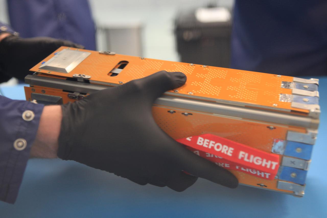
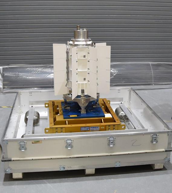
The Advanced Electrical Bus (ALBus) mission is a technology demonstration of resettable Shape Memory Alloy (SMA) mechanisms for deployable solar arrays and a pathfinder for high power density CubeSats. The mission has two primary objectives. The first is to demonstrate the functionality of the novel SMA activated solar array mechanisms in the on-orbit environment. The second objective is to assess the system level ability to charge a high capacity battery, distribute 100 W of electrical power and thermally control the 3-U CubeSat system. Performance from the mission will be used to mature the SMA mechanism designs for CubeSat applications and plan for future high power density CubeSat missions.

Jet Propulsion Laboratory (JPL) engineers examine the interface surface on the Cassini spacecraft prior to installation of the third radioisotope thermoelectric generator (RTG). The other two RTGs, at left, already are installed on Cassini. The three RTGs will be used to power Cassini on its mission to the Saturnian system. They are undergoing mechanical and electrical verification testing in the Payload Hazardous Servicing Facility. RTGs use heat from the natural decay of plutonium to generate electric power. The generators enable spacecraft to operate far from the Sun where solar power systems are not feasible. The Cassini mission is scheduled for an Oct. 6 launch aboard a Titan IVB/Centaur expendable launch vehicle. Cassini is built and managed for NASA by JPL
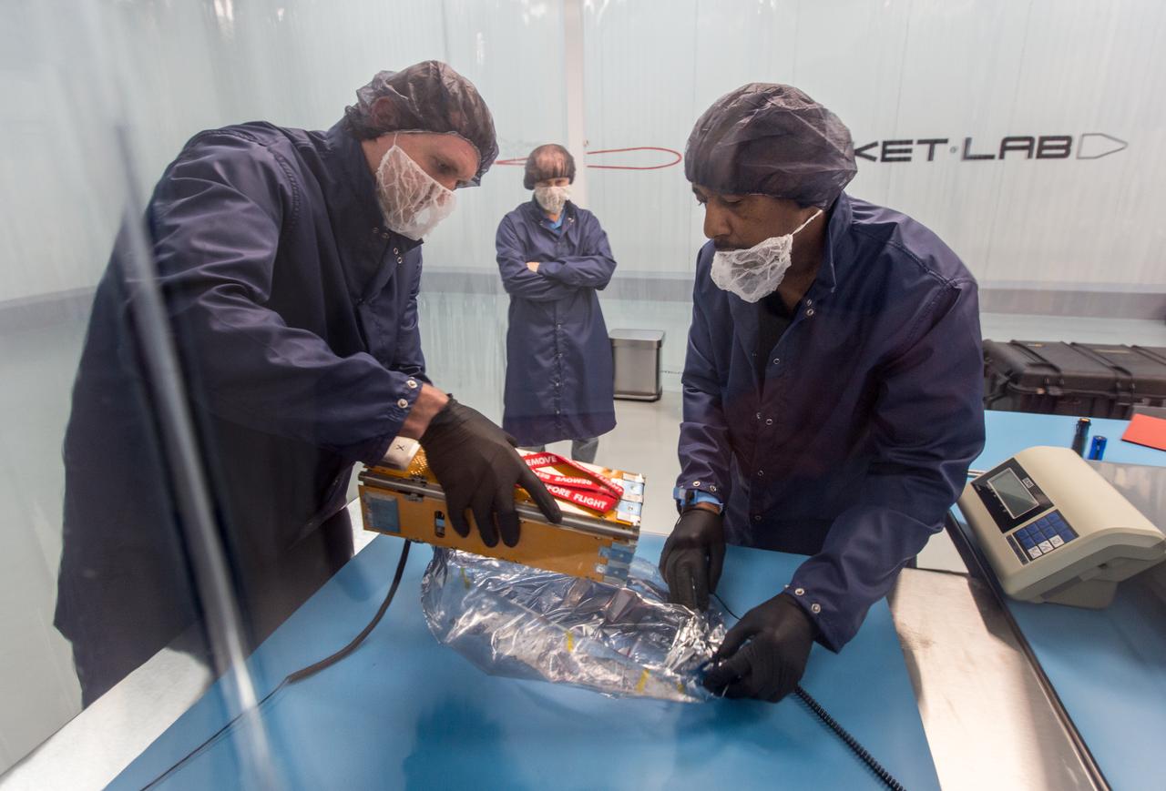
The Advanced Electrical Bus (ALBus) mission is a technology demonstration of resettable Shape Memory Alloy (SMA) mechanisms for deployable solar arrays and a pathfinder for high power density CubeSats. The mission has two primary objectives. The first is to demonstrate the functionality of the novel SMA activated solar array mechanisms in the on-orbit environment. The second objective is to assess the system level ability to charge a high capacity battery, distribute 100 W of electrical power and thermally control the 3-U CubeSat system. Performance from the mission will be used to mature the SMA mechanism designs for CubeSat applications and plan for future high power density CubeSat missions.
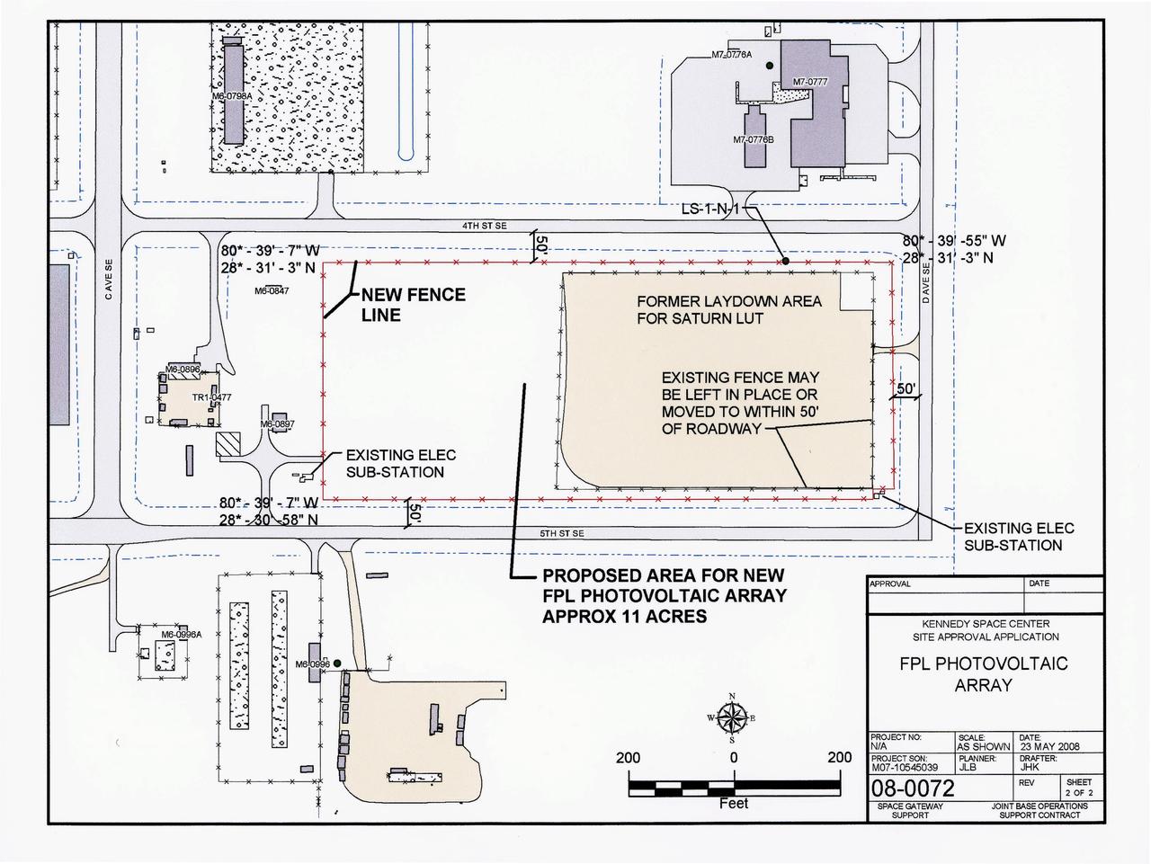
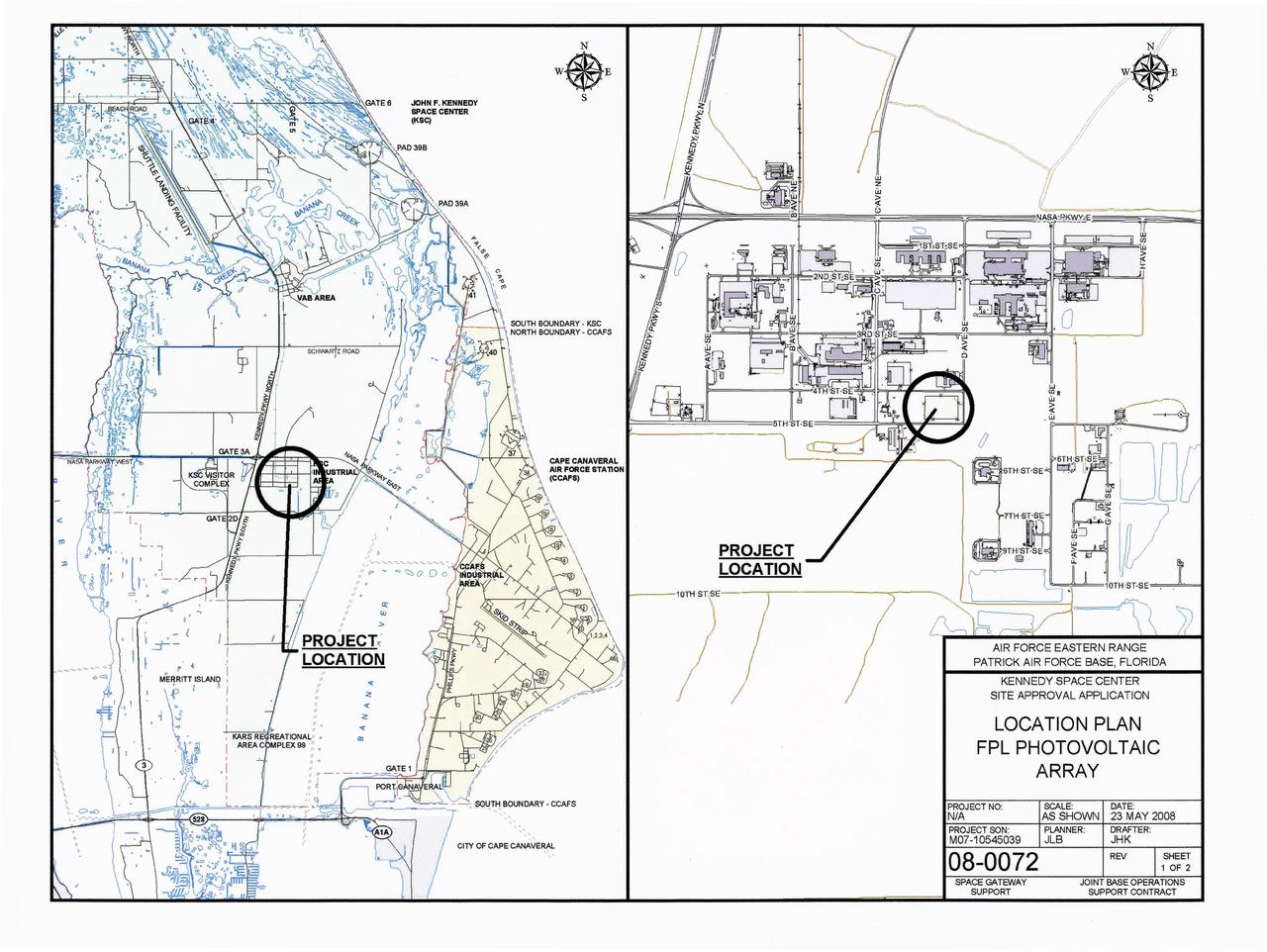
CAPE CANAVERAL, Fla. – This map shows the area within NASA's Kennedy Space Center where one of the two solar photovoltaic power generation systems will be built as the result of an agreement between NASA and Florida Power & Light. The agreement is part of a new initiative that will cut reliance on fossil fuels and improve the environment by reducing greenhouse gas emissions. The major facility will produce an estimated 10 megawatts of electrical power, which can serve roughly 3,000 homes. A separate one-megawatt solar power facility will support the electrical needs of the center.
Jet Propulsion Laboratory (JPL) workers prepare the installation cart (atop the platform) for removal of a radioisotope thermoelectric generator (RTG) from the adjacent Cassini spacecraft. This is the second of three RTGs being removed from Cassini after undergoing mechanical and electrical verification tests in the Payload Hazardous Servicing Facility. The third RTG to be removed is in background at left. The three RTGs will then be temporarily stored before being re-installed for flight. The RTGs will provide electrical power to Cassini on its 6.7-year trip to the Saturnian system and during its four-year mission at Saturn. RTGs use heat from the natural decay of plutonium to generate electric power. The generators enable spacecraft to operate far from the Sun where solar power systems are not feasible. The Cassini mission is scheduled for an Oct. 6 launch aboard a Titan IVB/Centaur expendable launch vehicle. Cassini is built and managed for NASA by JPL
Lockheed Martin Missile and Space Co. employees Joe Collingwood, at right, and Ken Dickinson retract pins in the storage base to release a radioisotope thermoelectric generator (RTG) in preparation for hoisting operations. This RTG and two others will be installed on the Cassini spacecraft for mechanical and electrical verification testing in the Payload Hazardous Servicing Facility. The RTGs will provide electrical power to Cassini on its 6.7-year trip to the Saturnian system and during its four-year mission at Saturn. RTGs use heat from the natural decay of plutonium to generate electric power. The generators enable spacecraft to operate at great distances from the Sun where solar power systems are not feasible. The Cassini mission is targeted for an Oct. 6 launch aboard a Titan IVB/Centaur expendable launch vehicle. Cassini is built and managed by NASA’s Jet Propulsion Laboratory
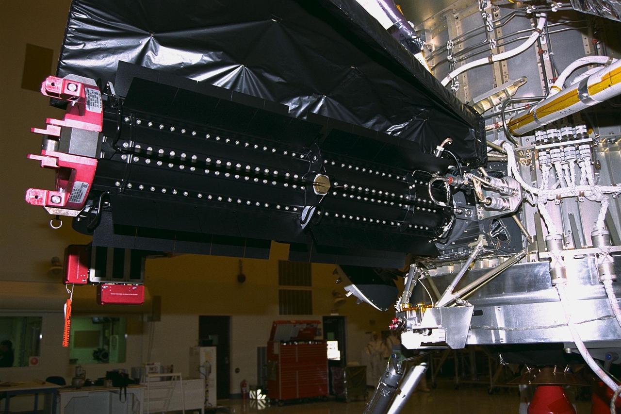
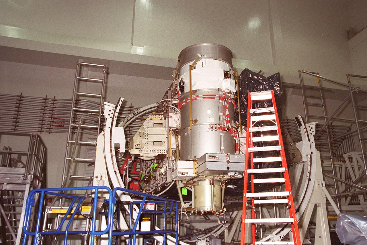
This radioisotope thermoelectric generator (RTG), at center, is ready for electrical verification testing now that it has been installed on the Cassini spacecraft in the Payload Hazardous Servicing Facility. A handling fixture, at far left, remains attached. This is the third and final RTG to be installed on Cassini for the prelaunch tests. The RTGs will provide electrical power to Cassini on its 6.7-year trip to the Saturnian system and during its four-year mission at Saturn. RTGs use heat from the natural decay of plutonium to generate electric power. The generators enable spacecraft to operate at great distances from the Sun where solar power systems are not feasible. The Cassini mission is targeted for an Oct. 6 launch aboard a Titan IVB/Centaur expendable launch vehicle
Jet Propulsion Laboratory (JPL) workers use a borescope to verify pressure relief device bellows integrity on a radioisotope thermoelectric generator (RTG) which has been installed on the Cassini spacecraft in the Payload Hazardous Servicing Facility. The activity is part of the mechanical and electrical verification testing of RTGs during prelaunch processing. RTGs use heat from the natural decay of plutonium to generate electric power. The three RTGs on Cassini will enable the spacecraft to operate far from the Sun where solar power systems are not feasible. They will provide electrical power to Cassini on its 6.7-year trip to the Saturnian system and during its four-year mission at Saturn. The Cassini mission is scheduled for an Oct. 6 launch aboard a Titan IVB/Centaur expendable launch vehicle. Cassini is built and managed for NASA by JPL
Carrying a neutron radiation detector, Fred Sanders (at center), a health physicist with the Jet Propulsion Laboratory (JPL), and other health physics personnel monitor radiation in the Payload Hazardous Servicing Facility after three radioisotope thermoelectric generators (RTGs) were installed on the Cassini spacecraft for mechanical and electrical verification tests. The RTGs will provide electrical power to Cassini on its 6.7-year trip to the Saturnian system and during its four-year mission at Saturn. RTGs use heat from the natural decay of plutonium to generate electric power. The generators enable spacecraft to operate at great distances from the Sun where solar power systems are not feasible. The Cassini mission is targeted for an Oct. 6 launch aboard a Titan IVB/Centaur expendable launch vehicle. Cassini is built and managed by JPL

This radioisotope thermoelectric generator (RTG), at center, will undergo mechanical and electrical verification testing now that it has been installed on the Cassini spacecraft in the Payload Hazardous Servicing Facility. A handling fixture, at far left, is still attached. Three RTGs will provide electrical power to Cassini on its 6.7-year trip to the Saturnian system and during its four-year mission at Saturn. RTGs use heat from the natural decay of plutonium to generate electric power. The generators enable spacecraft to operate far from the Sun where solar power systems are not feasible. The Cassini mission is scheduled for an Oct. 6 launch aboard a Titan IVB/Centaur expendable launch vehicle. Cassini is built and managed for NASA by the Jet Propulsion Laboratory
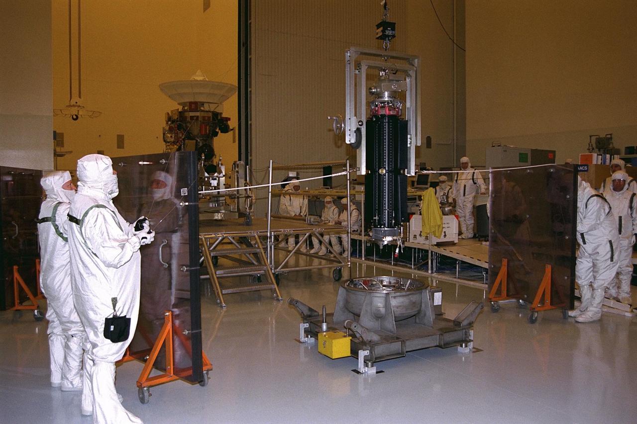
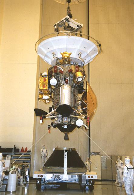
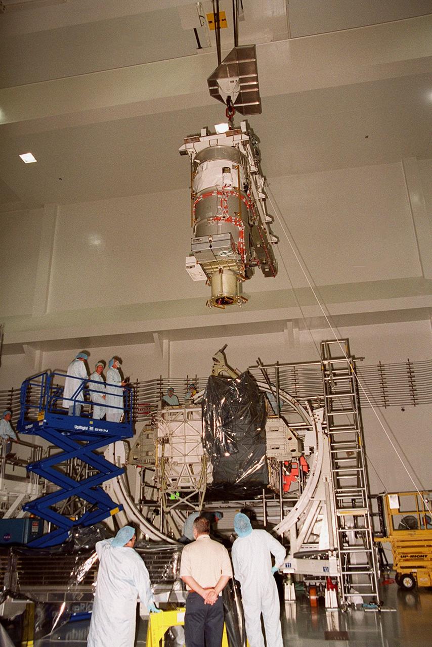
Supported on a lift fixture, this radioisotope thermoelectric generator (RTG), at center, is hoisted from its storage base using the airlock crane in the Payload Hazardous Servicing Facility (PHSF). Jet Propulsion Laboratory (JPL) workers are preparing to install the RTG onto the Cassini spacecraft, in background at left, for mechanical and electrical verification testing. The three RTGs on Cassini will provide electrical power to the spacecraft on its 6.7-year trip to the Saturnian system and during its four-year mission at Saturn. RTGs use heat from the natural decay of plutonium to generate electric power. The generators enable spacecraft to operate at great distances from the Sun where solar power systems are not feasible. The Cassini mission is targeted for an Oct. 6 launch aboard a Titan IVB/Centaur expendable launch vehicle. Cassini is built and managed by JPL
NASA Glenn Technician Mark Springowski works on a 10-kilowatt Stirling Power Conversion Unit, which is part of the Fission Surface Power Technology Demonstration Unit. This is a system level demonstration of a surface power system, which could potentially be used to support manned missions to the moon or Mars. A flight system would use 180 kilowatt nuclear fission reactor and four Stirling PCU’s to produce 40 kW of electricity for manned surface missions.
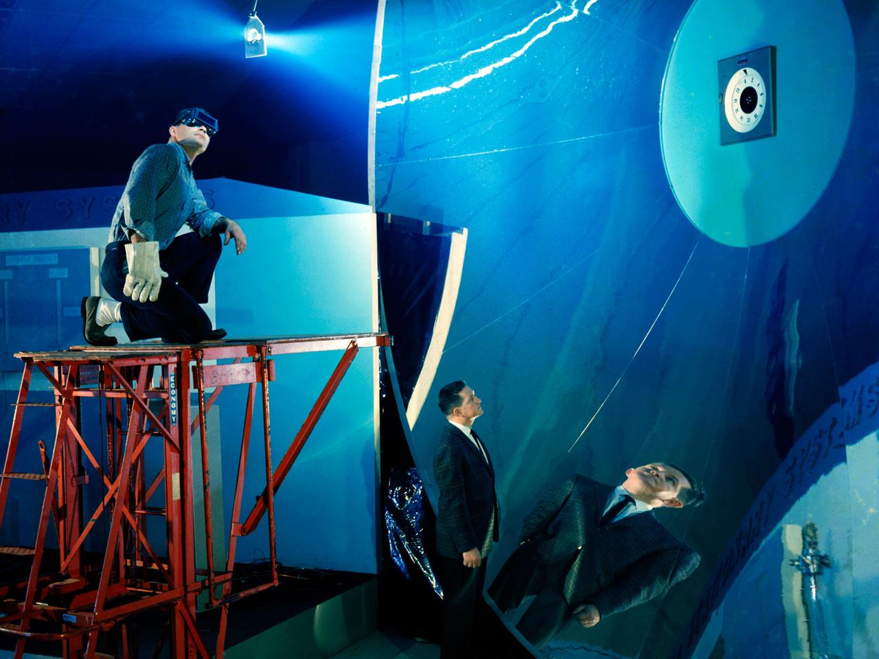
Testing of the Solar Dynamic Collector for Space Freedom. The solar dynamic power system includes a solar concentrator, which collects sunlight; a receiver, which accepts and stores the concentrated solar energy and transfers this energy to a gas; a Brayton turbine, alternator, and compressor unit, which generates electric power; and a radiator, which rejects waste heat.
Testing of the Solar Dynamic Collector for Space Freedom. The solar dynamic power system includes a solar concentrator, which collects sunlight; a receiver, which accepts and stores the concentrated solar energy and transfers this energy to a gas; a Brayton turbine, alternator, and compressor unit, which generates electric power; and a radiator, which rejects waste heat.
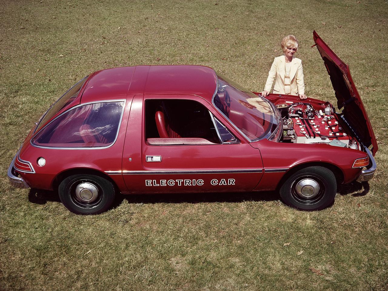
The National Aeronautics and Space Administration (NASA) Lewis Research Center tested 16 commercially-manufactured electric vehicles, including this modified Pacer, during the mid-1970s. The Electric Vehicle Project was just one of several energy-related programs that Lewis and the Energy Research and Development Administration (ERDA) undertook in the mid-1970s. NASA and ERDA embarked on this program in 1976 to determine the state of the current electric vehicle technology. As part of the project, Lewis tested a fleet composed of every commercially available electric car. The Cleveland-area Electric Vehicle Associates modified an American Motors Pacer vehicle to create this Change-of-Pace Coupe. It was powered by twenty 6-volt batteries whose voltage could be varied by a foot control. The tests analyzed the vehicle’s range, acceleration, coast-down, braking, and energy consumption. Some of the vehicles had analog data recording systems to measure the battery during operation and sensors to determine speed and distance. Lewis researchers found that the vehicle performance varied significantly from model to model. In general, the range, acceleration, and speed were lower than conventional vehicles. They also found that traditional gasoline-powered vehicles were as efficient as the electric vehicles. The researchers concluded, however, that advances in battery technology and electric drive systems would significantly improve the performance and efficiency.
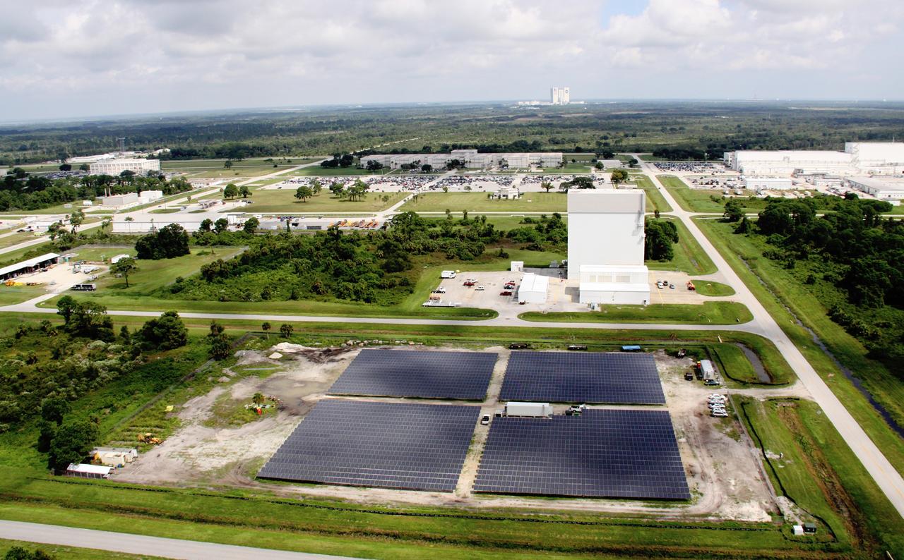
CAPE CANAVERAL, Fla. – An aerial view of the site in the Industrial Area of NASA's Kennedy Space Center in Florida where a solar power system is being built. The solar power systems are being constructed by NASA and Florida Power & Light Company as part of a public-private partnership that promotes a clean-energy future. This site located on 10 acres will produce about one megawatt of electricity for Kennedy to use. Photo credit: NASA/Troy Cryder
CAPE CANAVERAL, Fla. – An aerial view of the site in the Industrial Area of NASA's Kennedy Space Center in Florida where a solar power system is being built. The solar power systems are being constructed by NASA and Florida Power & Light Company as part of a public-private partnership that promotes a clean-energy future. This site located on 10 acres will produce about one megawatt of electricity for Kennedy to use. Photo credit: NASA/Troy Cryder
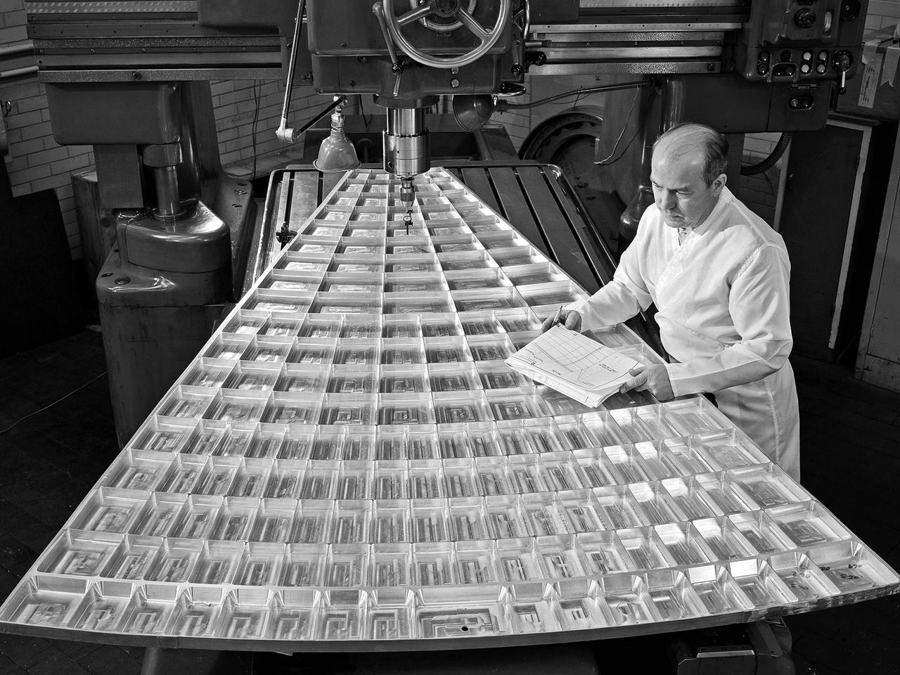
Daniel Bernatowicz, Chief of the Advanced Power Systems Branch at the National Aeronautics and Space Administration (NASA) Lewis Research Center, examines a 20-foot section of a solar mirror being fabricated in the Jig Bore Room of the Technical Services Building. NASA Lewis was conducting a wide-ranging effort to explore methods of generating electrical power for spacecraft. One method employed a large parabolic mirror to concentrate the sun’s energy. The mirror had to remain rigid and withstand micrometeoroids, but remain light and compact enough to be easily launched. In 1963 Bernatowicz and his researchers undertook a program to design a solar mirror to work with the Brayton cycle system on a space station. The mirror in this photograph was prepared for a conference on Advanced Technology in Space Power Systems held at Lewis in late August 1966. Lewis experts discussed advances with batteries, fuel cells, isotope and thermoelectric generators, and the SNAP-8 space power system. Lewis was developing several types of solar mirrors to work with a Brayton cycle electric generating system. The mirror’s 12 sections were shaped using a unique forming process developed at Lewis, coated with an epoxy, and plated with aluminum. The mirror concentrated the Sun's rays on a heat storage receiver containing lithium fluoride. This material was heated to produce power in a turbogenerator system, while additional heat was stored for use when the unit was in the Earth's shadow.
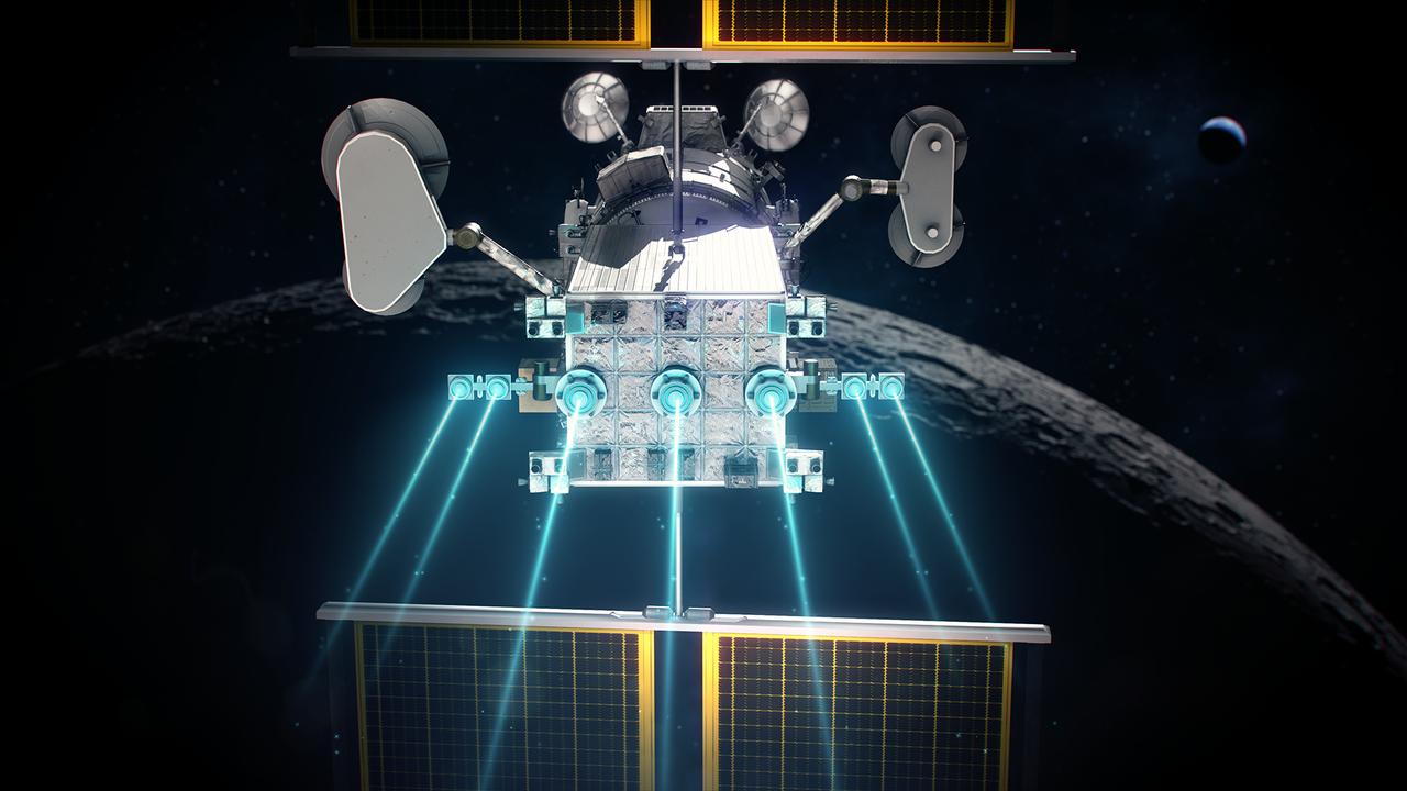
The Power and Propulsion Element's 12 kw thrusters will make Gateway the most powerful solar electric spacecraft ever flown.
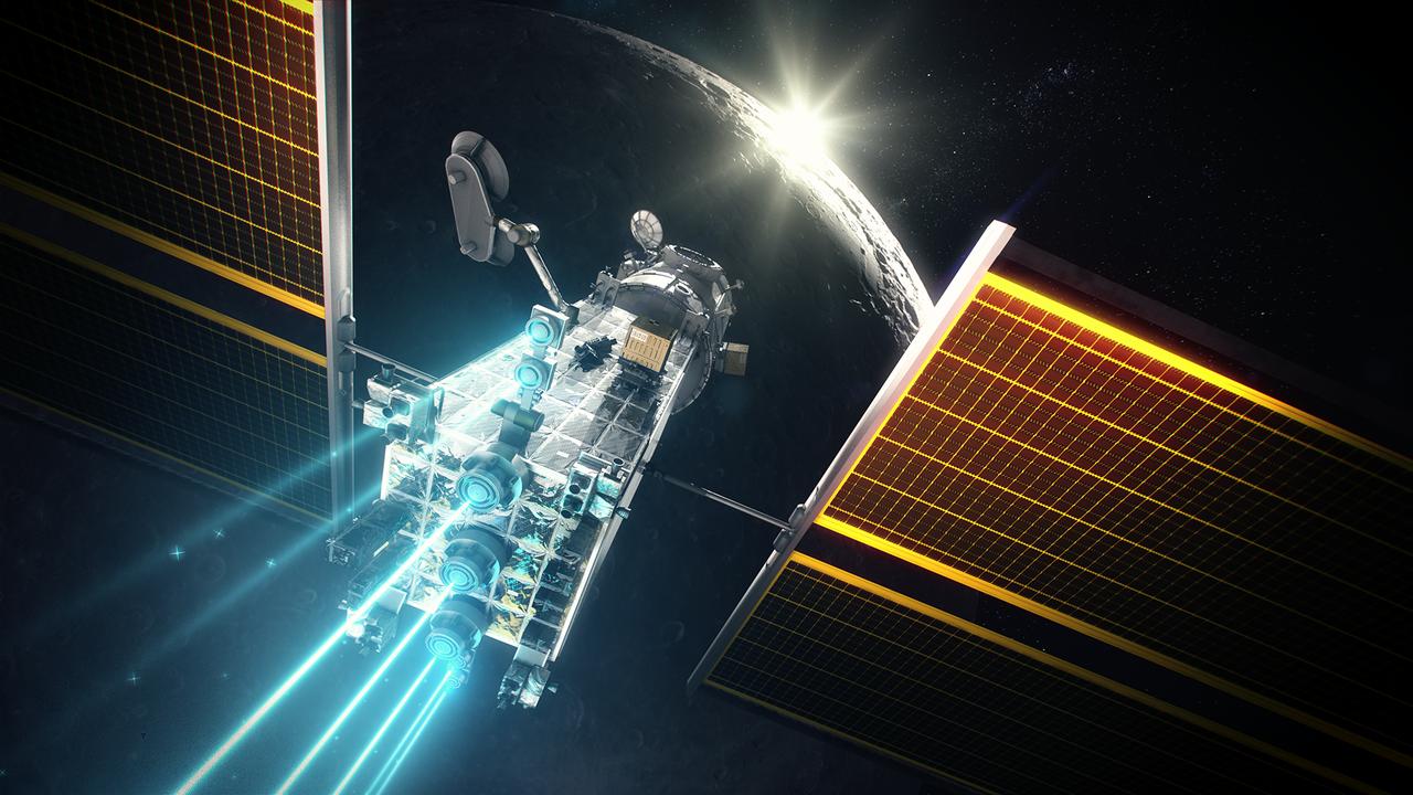
The Power and Propulsion Element's 12 kw thrusters will make Gateway the most powerful solar electric spacecraft ever flown.
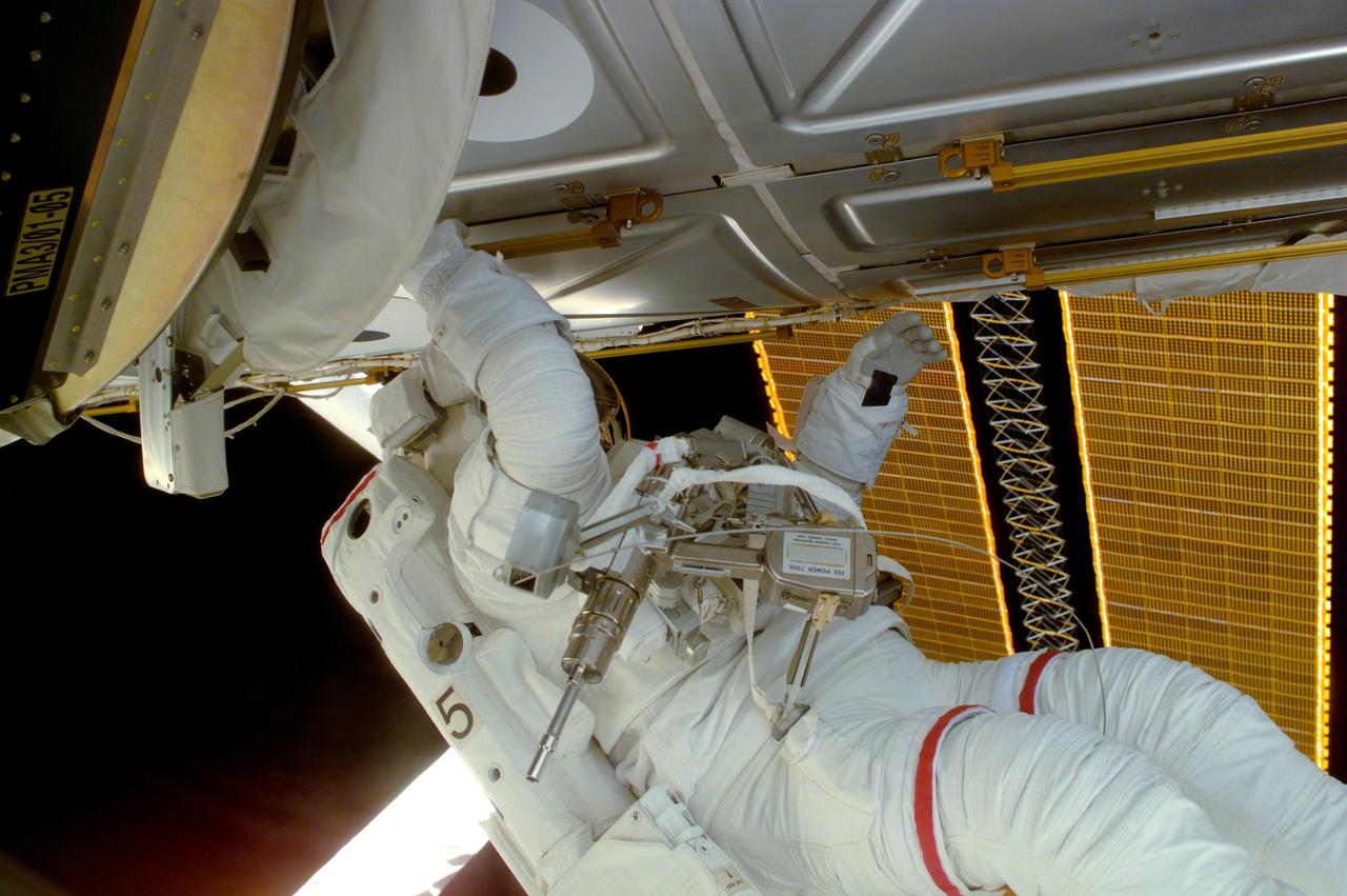
Astronaut Joseph R. Tanner, STS-97 mission specialist, is seen during a session of Extravehicular Activity (EVA), performing work on the International Space Station (ISS). Part of the Remote Manipulator System (RMS) arm and a section of the newly deployed solar array panel are in the background. The primary objective of the STS-97 mission was the delivery, assembly, and activation of the U.S. electrical power system on board the ISS. The electrical power system, which is built into a 73-meter (240-foot) long solar array structure consists of solar arrays, radiators, batteries, and electronics. The entire 15.4-metric ton (17-ton) package is called the P6 Integrated Truss Segment and is the heaviest and largest element yet delivered to the station aboard a space shuttle. The electrical system will eventually provide the power necessary for the first ISS crews to live and work in the U.S. segment. The STS-97 crew of five launched aboard the Space Shuttle Orbiter Endeavor on November 30, 2000 for an 11 day mission.
At Launch Complex 40 on Cape Canaveral Air Station, workers are installing three Radioisotope Thermoelectric Generators (RTGs) on the Cassini spacecraft. RTGs are lightweight, compact spacecraft electrical power systems that have flown successfully on 23 previous U.S. missions over the past 37 years. These generators produce power by converting heat into electrical energy; the heat is provided by the natural radioactive decay of plutonium-238 dioxide, a non-weapons-grade material. RTGs enable spacecraft to operate at significant distances from the Sun where solar power systems would not be feasible. Cassini will travel two billion miles to reach Saturn and another 1.1 billion miles while in orbit around Saturn. Cassini is undergoing final preparations for liftoff on a Titan IVB/Centaur launch vehicle, with the launch window opening at 4:55 a.m. EDT, Oct. 13
At Launch Complex 40 on Cape Canaveral Air Station, workers are installing three Radioisotope Thermoelectric Generators (RTGs) on the Cassini spacecraft. RTGs are lightweight, compact spacecraft electrical power systems that have flown successfully on 23 previous U.S. missions over the past 37 years. These generators produce power by converting heat into electrical energy; the heat is provided by the natural radioactive decay of plutonium-238 dioxide, a non-weapons-grade material. RTGs enable spacecraft to operate at significant distances from the Sun where solar power systems would not be feasible. Cassini will travel two billion miles to reach Saturn and another 1.1 billion miles while in orbit around Saturn. Cassini is undergoing final preparations for liftoff on a Titan IVB/Centaur launch vehicle, with the launch window opening at 4:55 a.m. EDT, Oct. 13
KENNEDY SPACE CENTER, FLA. -- At Launch Complex 40 on Cape Canaveral Air Station, workers are installing three Radioisotope Thermoelectric Generators (RTGs) on the Cassini spacecraft. RTGs are lightweight, compact spacecraft electrical power systems that have flown successfully on 23 previous U.S. missions over the past 37 years. These generators produce power by converting heat into electrical energy; the heat is provided by the natural radioactive decay of plutonium-238 dioxide, a non-weapons-grade material. RTGs enable spacecraft to operate at significant distances from the Sun where solar power systems would not be feasible. Cassini will travel two billion miles to reach Saturn and another 1.1 billion miles while in orbit around Saturn. Cassini is undergoing final preparations for liftoff on a Titan IVB/Centaur launch vehicle, with the launch window opening at 4:55 a.m. EDT, Oct. 13
At Launch Complex 40 on Cape Canaveral Air Station, one of three Radioisotope Thermoelectric Generators (RTGs) is being installed on the Cassini spacecraft. RTGs are lightweight, compact spacecraft electrical power systems that have flown successfully on 23 previous U.S. missions over the past 37 years. These generators produce power by converting heat into electrical energy; the heat is provided by the natural radioactive decay of plutonium-238 dioxide, a non-weapons-grade material. RTGs enable spacecraft to operate at significant distances from the Sun where solar power systems would not be feasible. Cassini will travel two billion miles to reach Saturn and another 1.1 billion miles while in orbit around Saturn. Cassini is undergoing final preparations for liftoff on a Titan IVB/Centaur launch vehicle, with the launch window opening at 4:55 a.m. EDT, Oct. 13
At Launch Complex 40 on Cape Canaveral Air Station, workers are installing three Radioisotope Thermoelectric Generators (RTGs) on the Cassini spacecraft. RTGs are lightweight, compact spacecraft electrical power systems that have flown successfully on 23 previous U.S. missions over the past 37 years. These generators produce power by converting heat into electrical energy; the heat is provided by the natural radioactive decay of plutonium-238 dioxide, a non-weapons-grade material. RTGs enable spacecraft to operate at significant distances from the Sun where solar power systems would not be feasible. Cassini will travel two billion miles to reach Saturn and another 1.1 billion miles while in orbit around Saturn. Cassini is undergoing final preparations for liftoff on a Titan IVB/Centaur launch vehicle, with the launch window opening at 4:55 a.m. EDT, Oct. 13
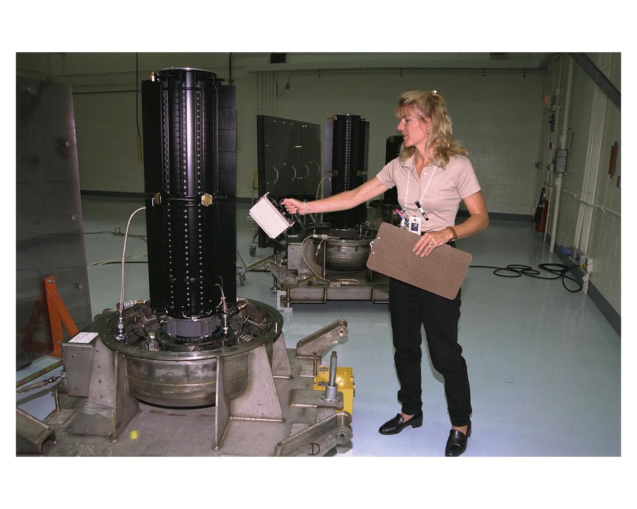
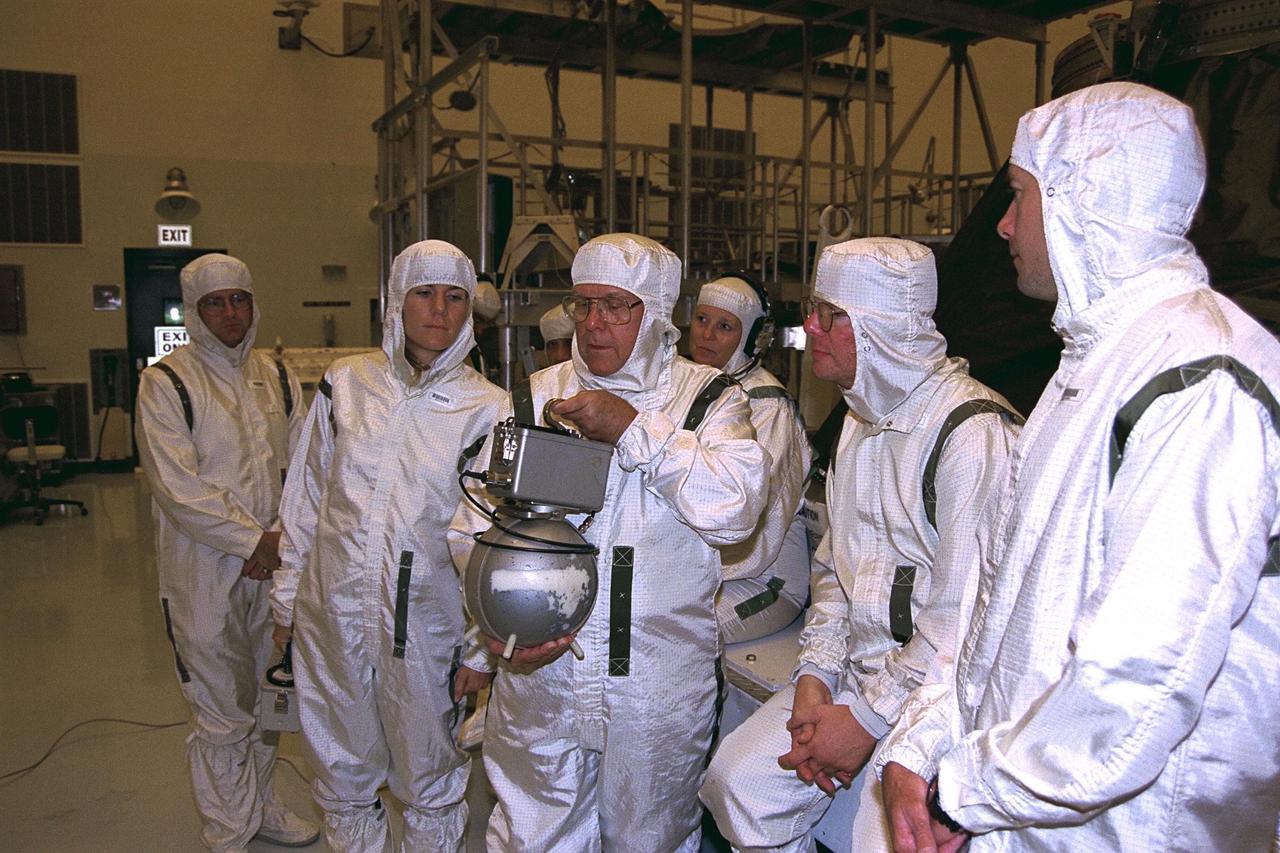
Environmental Health Specialist Jamie A. Keeley, of EG&G Florida Inc., uses an ion chamber dose rate meter to measure radiation levels in one of three radioisotope thermoelectric generators (RTGs) that will provide electrical power to the Cassini spacecraft on its mission to explore the Saturnian system. The three RTGs and one spare are being tested and mointored in the Radioisotope Thermoelectric Generator Storage Building in the KSC's Industrial Area. The RTGs use heat from the natural decay of plutonium to generate electric power. RTGs enable spacecraft to operate far from the Sun where solar power systems are not feasible. The RTGs on Cassini are of the same design as those flying on the already deployed Galileo and Ulysses spacecraft. The Cassini mission is targeted for an Oct. 6 launch aboard a Titan IVB/Centaur expendable launch vehicle.
At Launch Complex 40 on Cape Canaveral Air Station, workers are installing three Radioisotope Thermoelectric Generators (RTGs) on the Cassini spacecraft. RTGs are lightweight, compact spacecraft electrical power systems that have flown successfully on 23 previous U.S. missions over the past 37 years. These generators produce power by converting heat into electrical energy; the heat is provided by the natural radioactive decay of plutonium-238 dioxide, a non-weapons-grade material. RTGs enable spacecraft to operate at significant distances from the Sun where solar power systems would not be feasible. Cassini will travel two billion miles to reach Saturn and another 1.1 billion miles while in orbit around Saturn. Cassini is undergoing final preparations for liftoff on a Titan IVB/Centaur launch vehicle, with the launch window opening at 4:55 a.m. EDT, Oct. 13
KENNEDY SPACE CENTER, FLA. -- At Launch Complex 40 on Cape Canaveral Air Station, workers are installing three Radioisotope Thermoelectric Generators (RTGs) on the Cassini spacecraft. RTGs are lightweight, compact spacecraft electrical power systems that have flown successfully on 23 previous U.S. missions over the past 37 years. These generators produce power by converting heat into electrical energy; the heat is provided by the natural radioactive decay of plutonium-238 dioxide, a non-weapons-grade material. RTGs enable spacecraft to operate at significant distances from the Sun where solar power systems would not be feasible. Cassini will travel two billion miles to reach Saturn and another 1.1 billion miles while in orbit around Saturn. Cassini is undergoing final preparations for liftoff on a Titan IVB/Centaur launch vehicle, with the launch window opening at 4:55 a.m. EDT, Oct. 13
In the Space Station Processing Facility, Solar Array Wing-3, an element of the International Space Station, is lifted from a work stand to move it to the Integrated Electronic Assembly for testing. The solar array is scheduled to be launched on STS-97 in late November along with the P6 truss. The Station’s electrical power system (EPS) will use eight photovoltaic solar arrays to convert sunlight to electricity. Each of the eight solar arrays will be 112 feet long by 39 feet wide. The solar arrays are mounted on a “blanket” that can be folded like an accordion for delivery. Once in orbit, astronauts will deploy the blankets to their full size. Gimbals will be used to rotate the arrays so that they will face the Sun to provide maximum power to the Space Station
In the Space Station Processing Facility, Solar Array Wing-3, a component of the International Space Station, is installed in the Integrated Electronic Assembly where it will be tested. The solar array is scheduled to be launched on STS-97 in late November along with the P6 truss. The Station’s electrical power system (EPS) will use eight photovoltaic solar arrays to convert sunlight to electricity. Each of the eight solar arrays will be 112 feet long by 39 feet wide. The solar arrays are mounted on a “blanket” that can be folded like an accordion for delivery. Once in orbit, astronauts will deploy the blankets to their full size. Gimbals will be used to rotate the arrays so that they will face the Sun to provide maximum power to the Space Station
In the Space Station Processing Facility, Solar Array Wing-3 (at top), a component of the International Space Station, hovers above the Integrated Electronic Assembly where it will be installed for testing. The solar array is scheduled to be launched on STS-97 in late November along with the P6 truss. The Station’s electrical power system (EPS) will use eight photovoltaic solar arrays to convert sunlight to electricity. Each of the eight solar arrays will be 112 feet long by 39 feet wide. The solar arrays are mounted on a “blanket” that can be folded like an accordion for delivery. Once in orbit, astronauts will deploy the blankets to their full size. Gimbals will be used to rotate the arrays so that they will face the Sun to provide maximum power to the Space Station
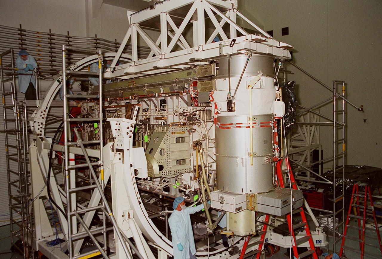
In the Space Station Processing Facility, Solar Array Wing-3, a component of the International Space Station, is installed in the Integrated Electronic Assembly where it will be tested. The solar array is scheduled to be launched on STS-97 in late November along with the P6 truss. The Station’s electrical power system (EPS) will use eight photovoltaic solar arrays to convert sunlight to electricity. Each of the eight solar arrays will be 112 feet long by 39 feet wide. The solar arrays are mounted on a “blanket” that can be folded like an accordion for delivery. Once in orbit, astronauts will deploy the blankets to their full size. Gimbals will be used to rotate the arrays so that they will face the Sun to provide maximum power to the Space Station
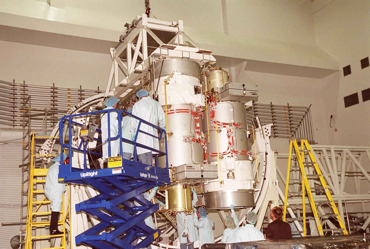
A solar array is nearly in place on the Integrated Equipment Assembly, next to Solar Array Wing-3, which is already installed. Components of the International Space Station, the arrays are scheduled to be launched on mission STS-97 in late November along with the P6 truss. The Station’s electrical power system (EPS) will use eight photovoltaic solar arrays to convert sunlight to electricity. Each of the eight solar arrays will be 112 feet long by 39 feet wide. The solar arrays are mounted on a “blanket” that can be folded like an accordion for delivery. Once in orbit, astronauts will deploy the blankets to their full size. Gimbals will be used to rotate the arrays so that they will face the Sun to provide maximum power to the Space Station

Tour of the Electrified Powertrain Flight Demonstration in the HyPER lab on June 17th, 2024 at Glenn Research Center. NASA’s Electrified Powertrain Flight Demonstration (EPFD) project focuses advancing the future of sustainable aviation by turning hybrid electric flight into a reality. HyPER is a hardware-in-the-loop laboratory that was designed specifically to investigate the dynamic interactions between turbomachinery, the electric power system, and the constantly varying loads of electrified aircraft. It is a small-scale lab capable of rapid reconfiguration through software. This allows the emulation of new engines using simulation models that are easily replaced and then appropriately scaled for power and inertia to the test hardware. Photo Credit: (NASA/Sara Lowthian-Hanna)
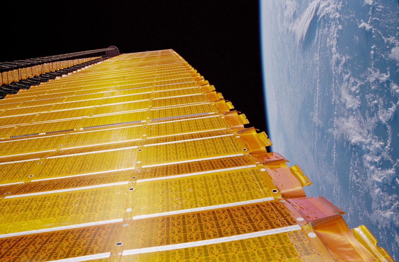
STS097-376-006 (7 Dec 2000) --- A close-up view of the P6 solar array on the International Space Station (ISS), backdropped against the blackness of space and the Earth?s horizon. The P6 solar array is the first of eight sets of solar arrays that at the completion of the space station construction in 2006, will comprise the station?s electrical power system, converting sunlight to electricity.
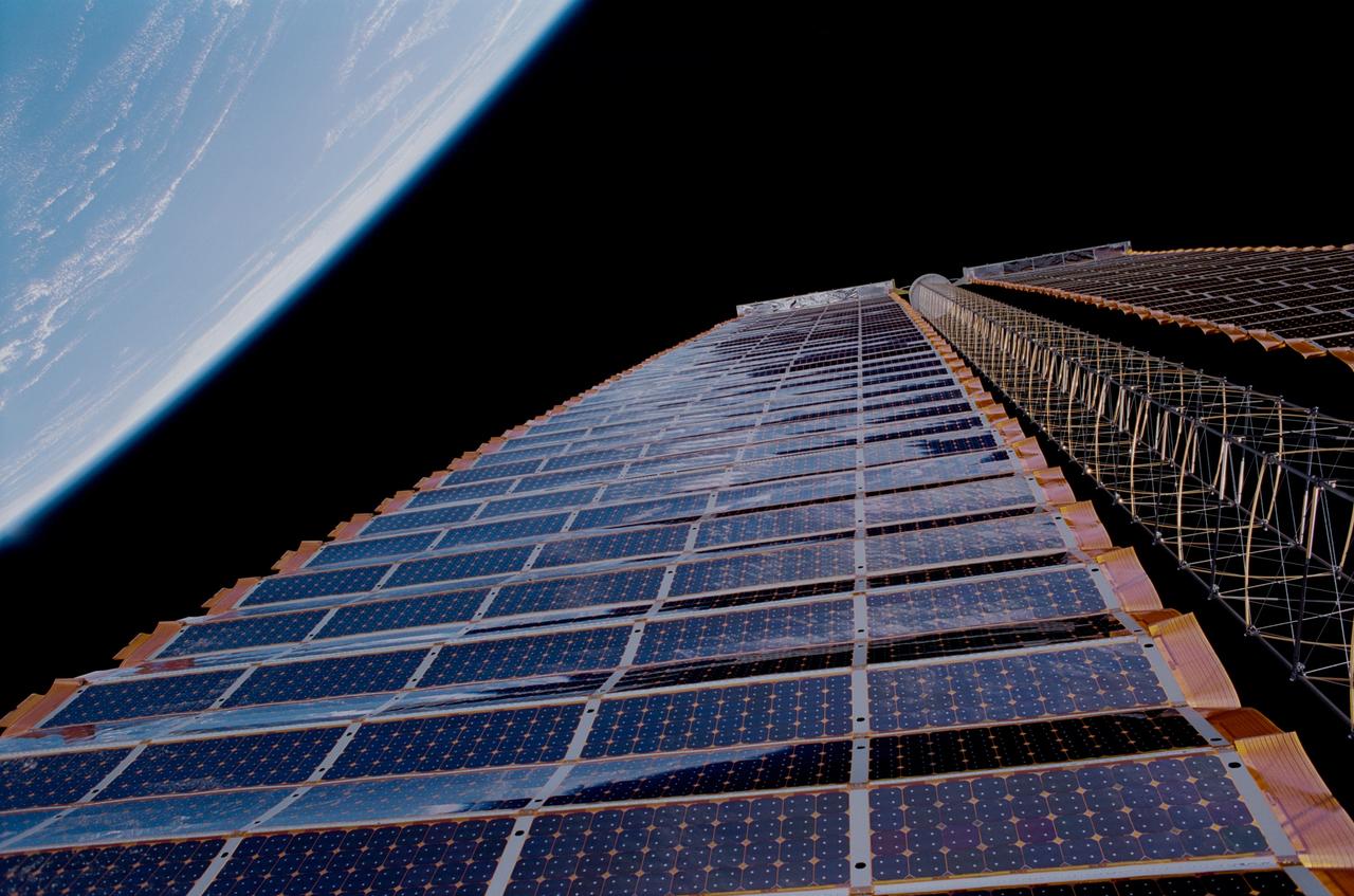
STS097-376-019 (7 December 2000) --- A close-up view of the P6 solar array on the International Space Station (ISS), backdropped against the blackness of space and the Earth’s horizon. The P6 solar array is the first of eight sets of solar arrays that at the completion of the space station construction in 2006, will comprise the station’s electrical power system, converting sunlight to electricity.
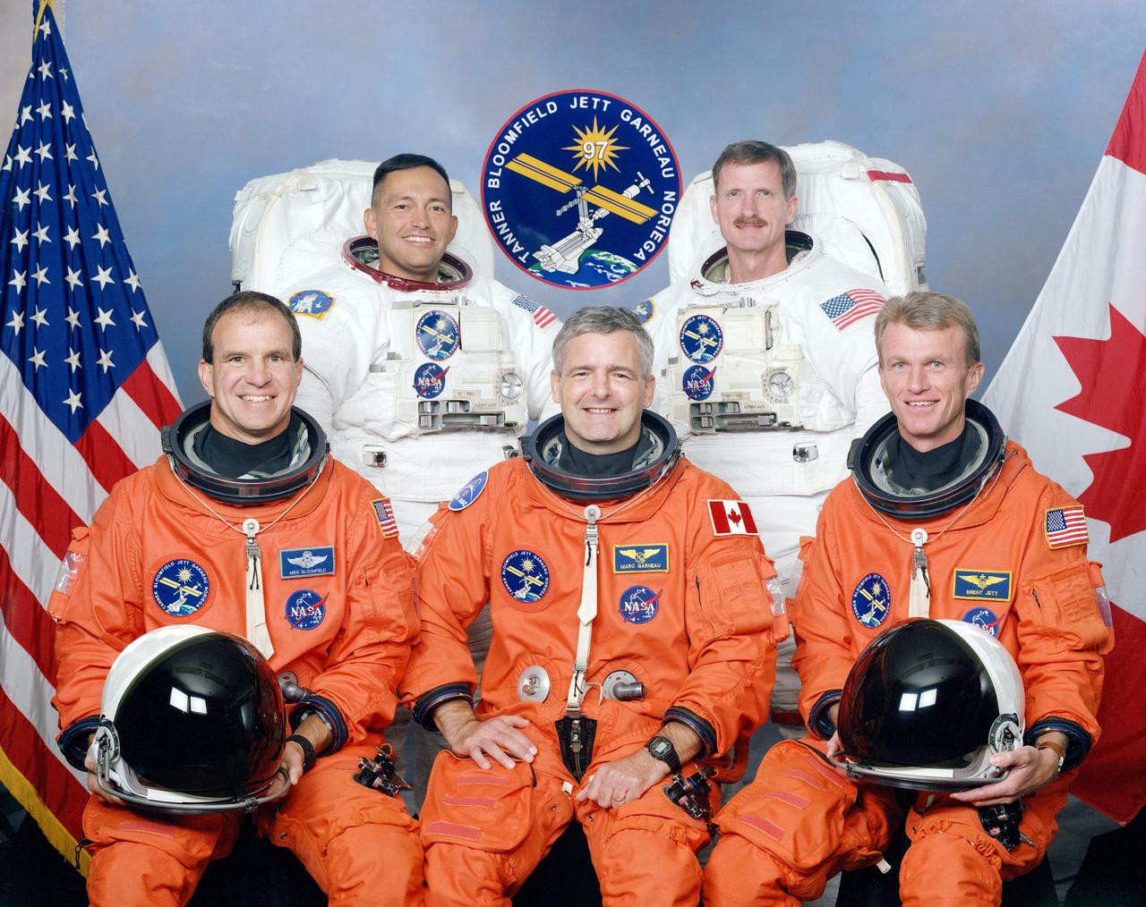
These five STS-97 crew members posed for a traditional portrait during training. On the front row, left to right, are astronauts Michael J. Bloomfield, pilot; Marc Garneau, mission specialist representing the Canadian Space Agency (CSA); and Brent W. Jett, Jr., commander. In the rear, wearing training versions of the extravehicular mobility unit (EMU) space suits, (left to right) are astronauts Carlos I. Noriega, and Joseph R. Tarner, both mission specialists. The primary objective of the STS-97 mission was the delivery, assembly, and activation of the U.S. electrical power system onboard the International Space Station (ISS). The electrical power system, which is built into a 73-meter (240-foot) long solar array structure consists of solar arrays, radiators, batteries, and electronics. The entire 15.4-metric ton (17-ton) package is called the P6 Integrated Truss Segment and is the heaviest and largest element yet delivered to the station aboard a space shuttle. The electrical system will eventually provide the power necessary for the first ISS crews to live and work in the U.S. segment. The STS-97 crew of five launched aboard the Space Shuttle Orbiter Endeavor on November 30, 2000 for an 11 day mission.
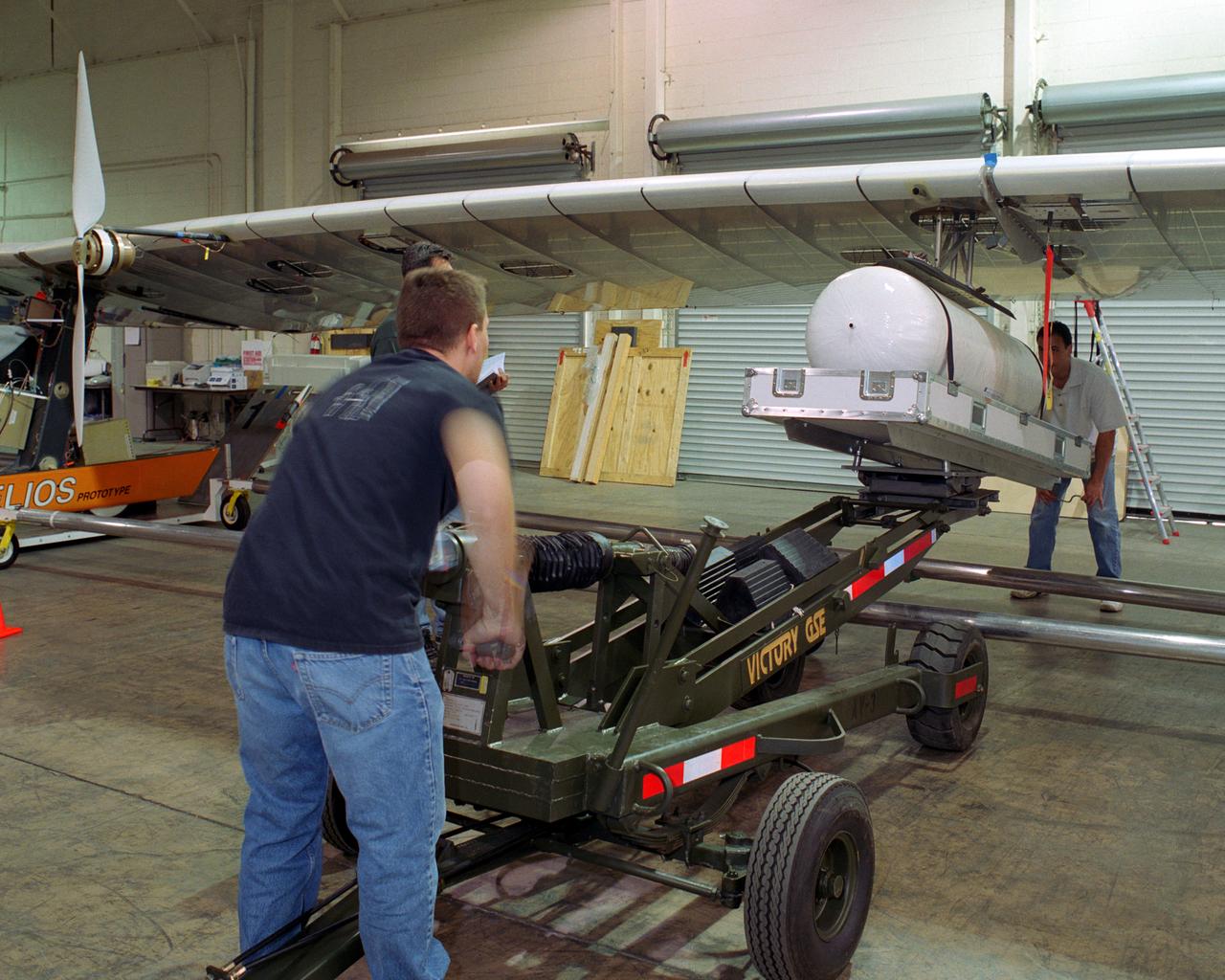
Technicians for AeroVironment, Inc., jack up a pressure tank to the wing of the Helios Prototype solar-electric flying wing. The tank carries pressurized hydrogen to fuel an experimental fuel cell system that powered the aircraft at night during an almost two-day long-endurance flight demonstration in the summer of 2003.
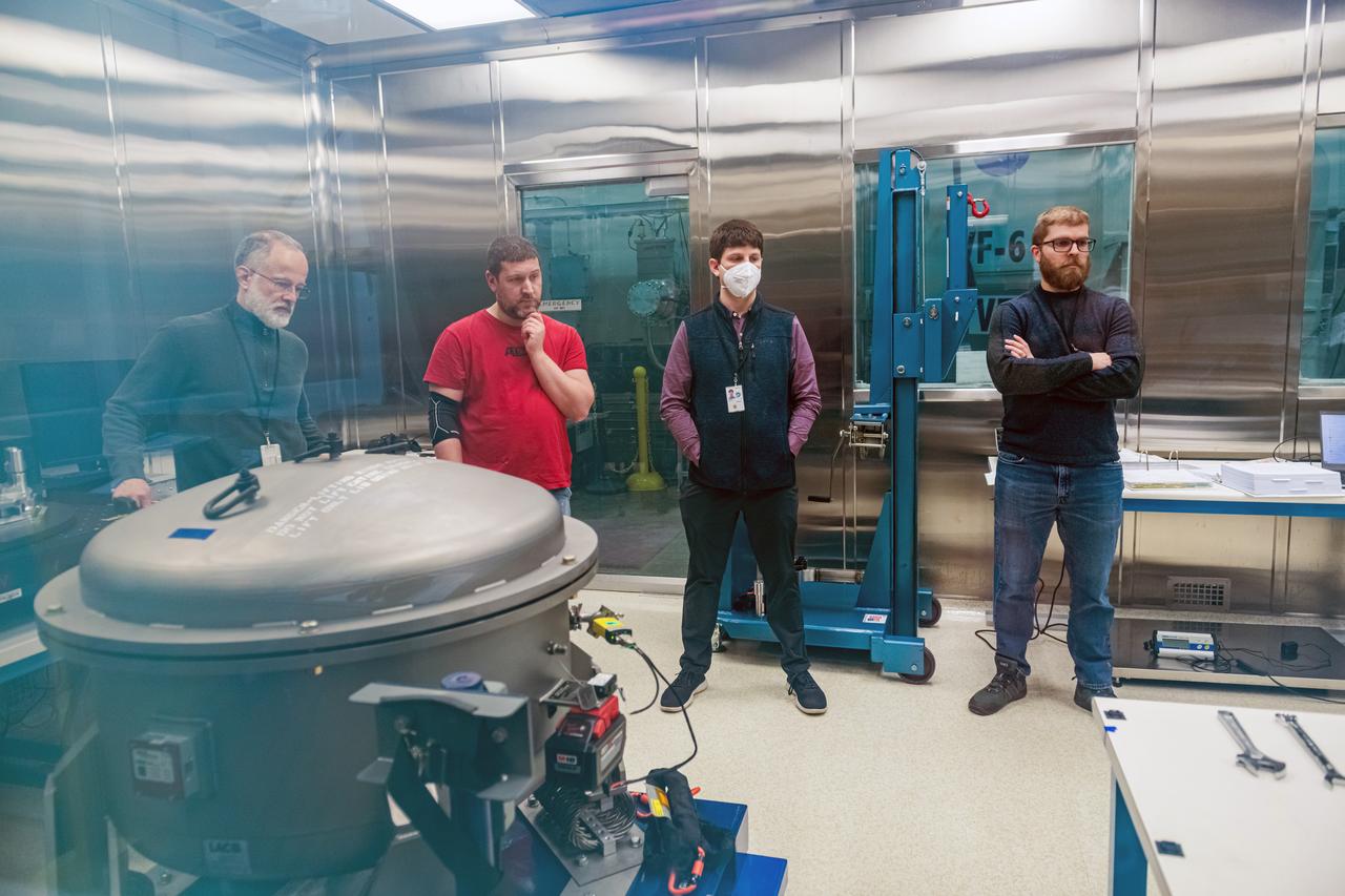
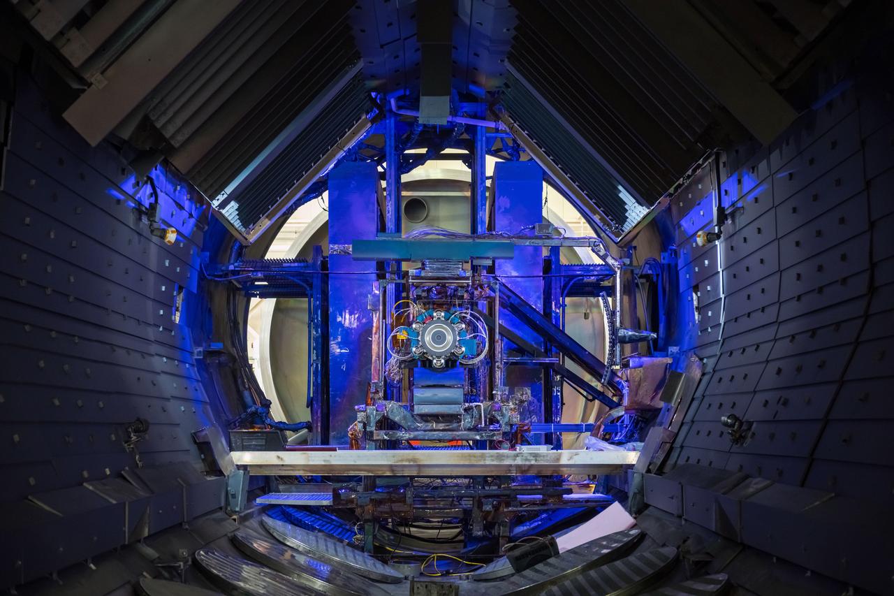
NASA Glenn Research Center has received the first of three Advanced Electric Propulsion System (AEPS) thrusters for the Gateway lunar space station. Built by L3Harris Technologies, the thruster will undergo testing before integration with Gateway’s Power and Propulsion Element, launching with the HALO module ahead of Artemis IV.

NASA Glenn Research Center has received the first of three Advanced Electric Propulsion System (AEPS) thrusters for the Gateway lunar space station. Built by L3Harris Technologies, the thruster will undergo testing before integration with Gateway’s Power and Propulsion Element, launching with the HALO module ahead of Artemis IV.
NASA Glenn Research Center has received the first of three Advanced Electric Propulsion System (AEPS) thrusters for the Gateway lunar space station. Built by L3Harris Technologies, the thruster will undergo testing before integration with Gateway’s Power and Propulsion Element, launching with the HALO module ahead of Artemis IV.
NASA Glenn Research Center has received the first of three Advanced Electric Propulsion System (AEPS) thrusters for the Gateway lunar space station. Built by L3Harris Technologies, the thruster will undergo testing before integration with Gateway’s Power and Propulsion Element, launching with the HALO module ahead of Artemis IV.

NASA Glenn Research Center has received the first of three Advanced Electric Propulsion System (AEPS) thrusters for the Gateway lunar space station. Built by L3Harris Technologies, the thruster will undergo testing before integration with Gateway’s Power and Propulsion Element, launching with the HALO module ahead of Artemis IV.
NASA Glenn Research Center has received the first of three Advanced Electric Propulsion System (AEPS) thrusters for the Gateway lunar space station. Built by L3Harris Technologies, the thruster will undergo testing before integration with Gateway’s Power and Propulsion Element, launching with the HALO module ahead of Artemis IV.
NASA Glenn Research Center has received the first of three Advanced Electric Propulsion System (AEPS) thrusters for the Gateway lunar space station. Built by L3Harris Technologies, the thruster will undergo testing before integration with Gateway’s Power and Propulsion Element, launching with the HALO module ahead of Artemis IV.
NASA Glenn Research Center has received the first of three Advanced Electric Propulsion System (AEPS) thrusters for the Gateway lunar space station. Built by L3Harris Technologies, the thruster will undergo testing before integration with Gateway’s Power and Propulsion Element, launching with the HALO module ahead of Artemis IV.
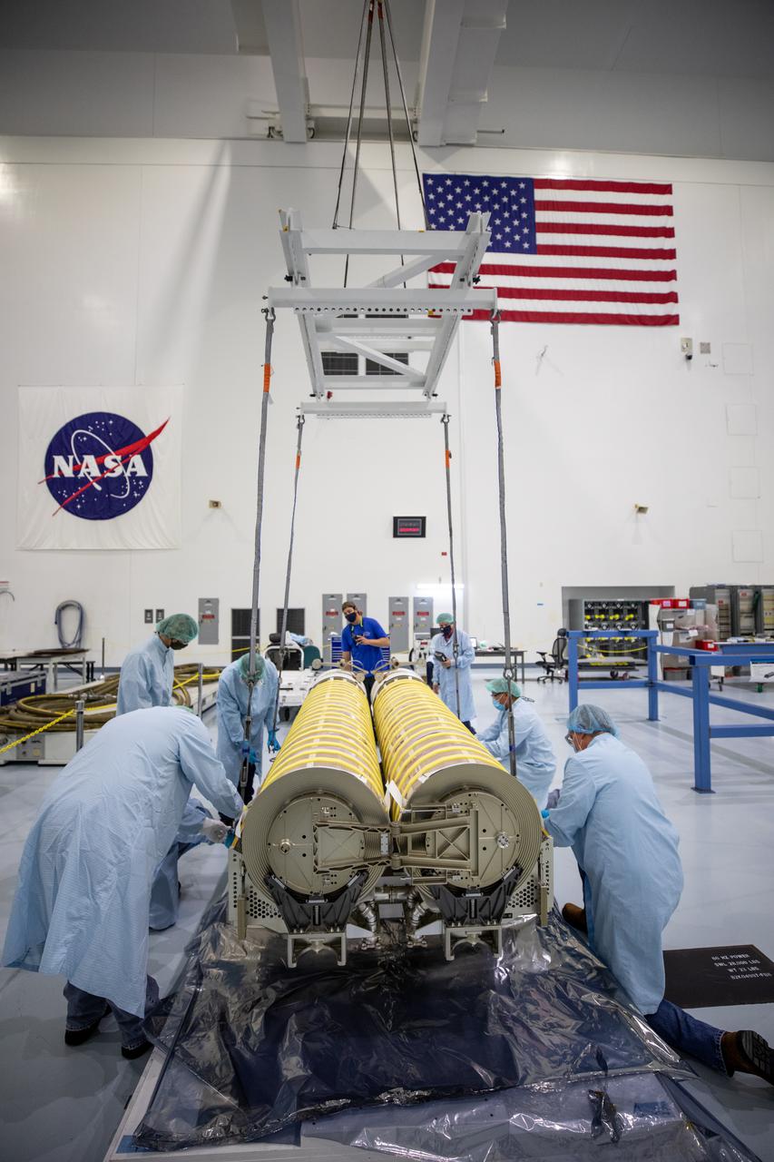
NASA and Boeing workers move solar arrays for the International Space Station to flight support equipment in the high bay of the Space Station Processing Facility at NASA’s Kennedy Space Center in Florida on April 2, 2021. The 63- by- 20-foot solar arrays will launch to the International Space Station later this year. They are the first two of six new solar arrays that in total will produce more than 120 kilowatts of electricity from the Sun’s energy, enough to power more than 40 average U.S. homes. Combined with the eight original, larger arrays, this advanced hardware will provide 215 kilowatts of energy, a 20 to 30 percent increase in power, helping maximize the space station’s capabilities for years to come. The arrays will produce electricity to sustain the station’s systems and equipment, plus augment the electricity available to continue a wide variety of public and private experiments and research in the microgravity environment of low-Earth orbit.
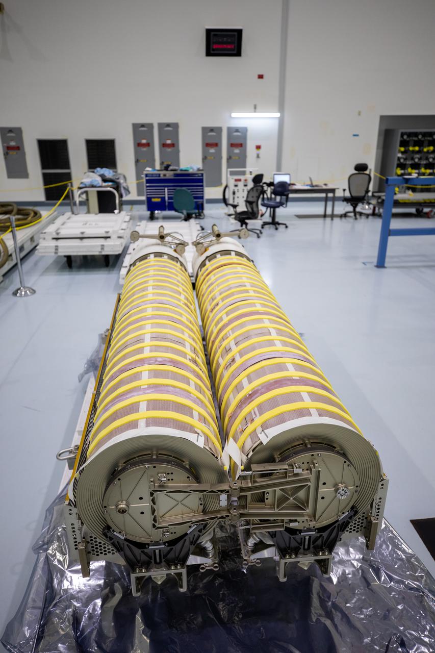
In view are the first two of six solar arrays shortly before NASA and Boeing workers began lifting them into flight support equipment the Space Station Processing Facility at NASA’s Kennedy Space Center in Florida on April 2, 2021. The 63- by- 20-foot solar arrays will launch to the International Space Station later this year. The six new solar arrays in total will produce more than 120 kilowatts of electricity from the Sun’s energy, enough to power more than 40 average U.S. homes. Combined with the eight original, larger arrays, this advanced hardware will provide 215 kilowatts of energy, a 20 to 30 percent increase in power, helping maximize the space station’s capabilities for years to come. The arrays will produce electricity to sustain the station’s systems and equipment, plus augment the electricity available to continue a wide variety of public and private experiments and research in the microgravity environment of low-Earth orbit.
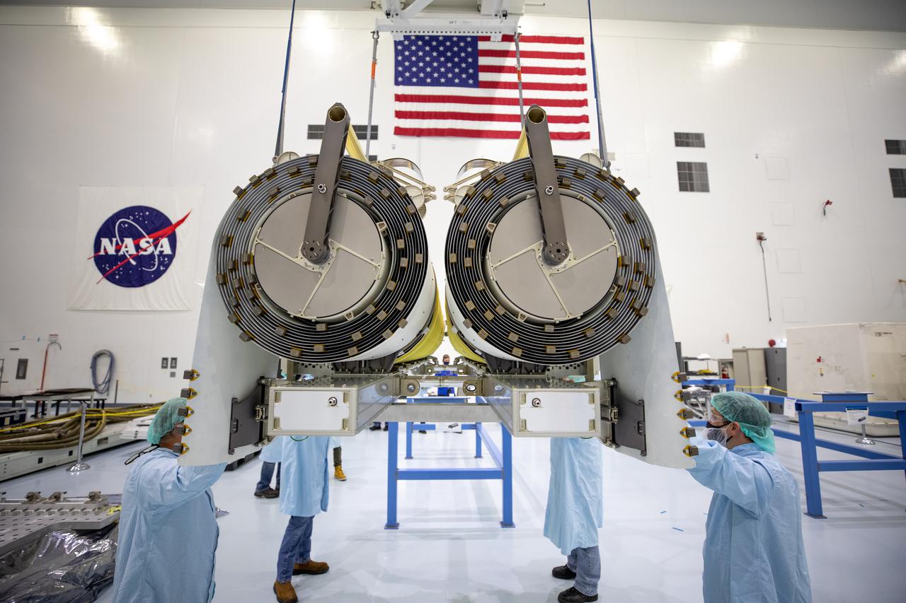
NASA and Boeing workers help position the solar arrays onto flight support equipment inside the high bay of the Space Station Processing Facility at NASA’s Kennedy Space Center in Florida on April 2, 2021. The 63- by- 20-foot solar arrays will launch to the International Space Station later this year. They are the first two of six new solar arrays that in total will produce more than 120 kilowatts of electricity from the Sun’s energy, enough to power more than 40 average U.S. homes. Combined with the eight original, larger arrays, this advanced hardware will provide 215 kilowatts of energy, a 20 to 30 percent increase in power, helping maximize the space station’s capabilities for years to come. The arrays will produce electricity to sustain the station’s systems and equipment, plus augment the electricity available to continue a wide variety of public and private experiments and research in the microgravity environment of low-Earth orbit.
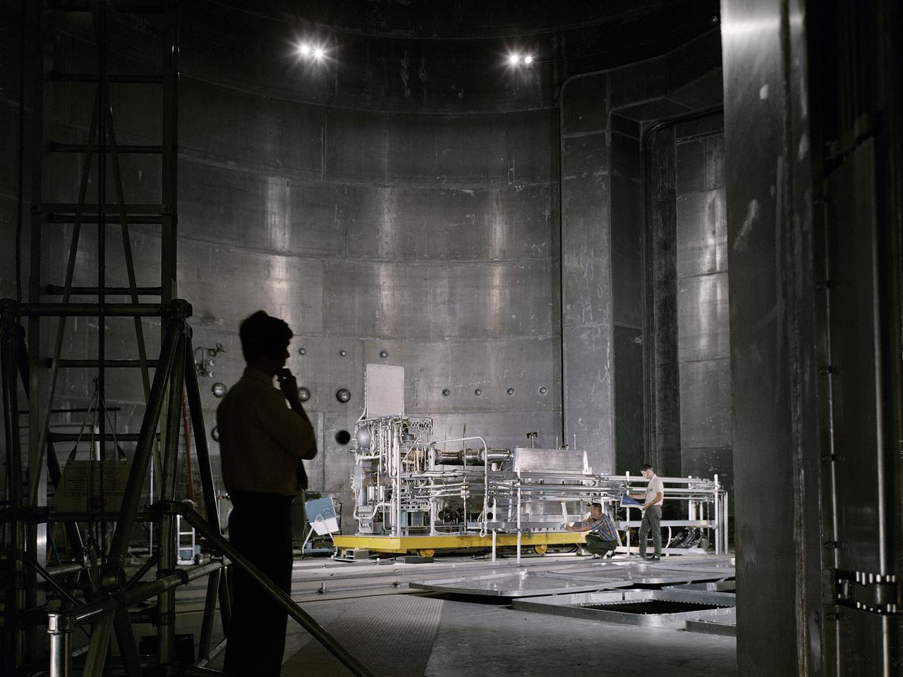
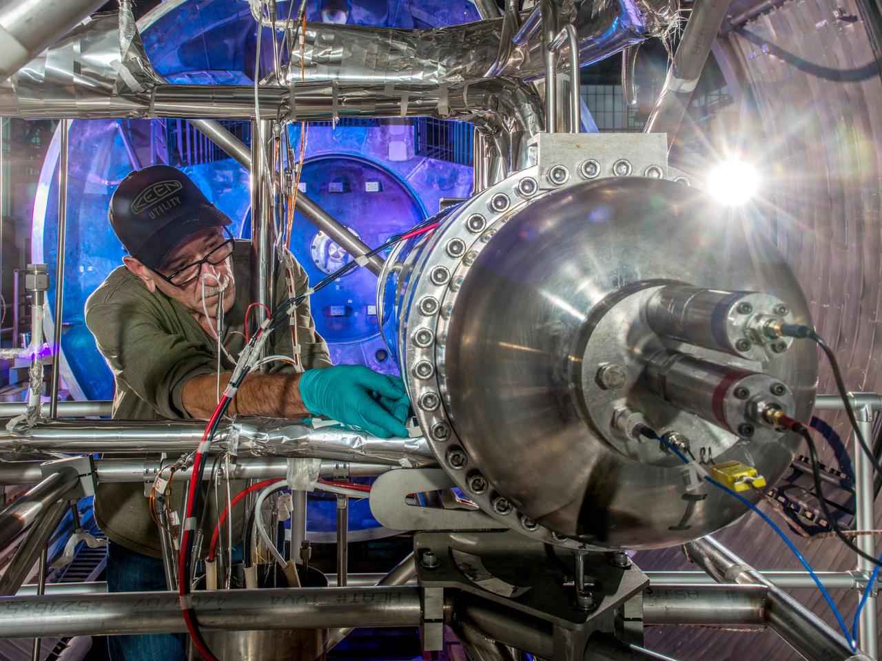
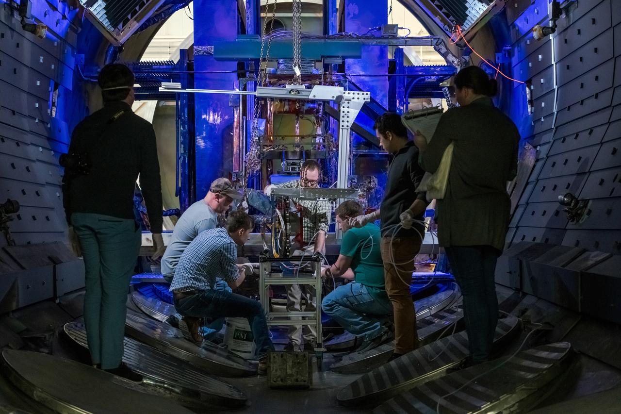
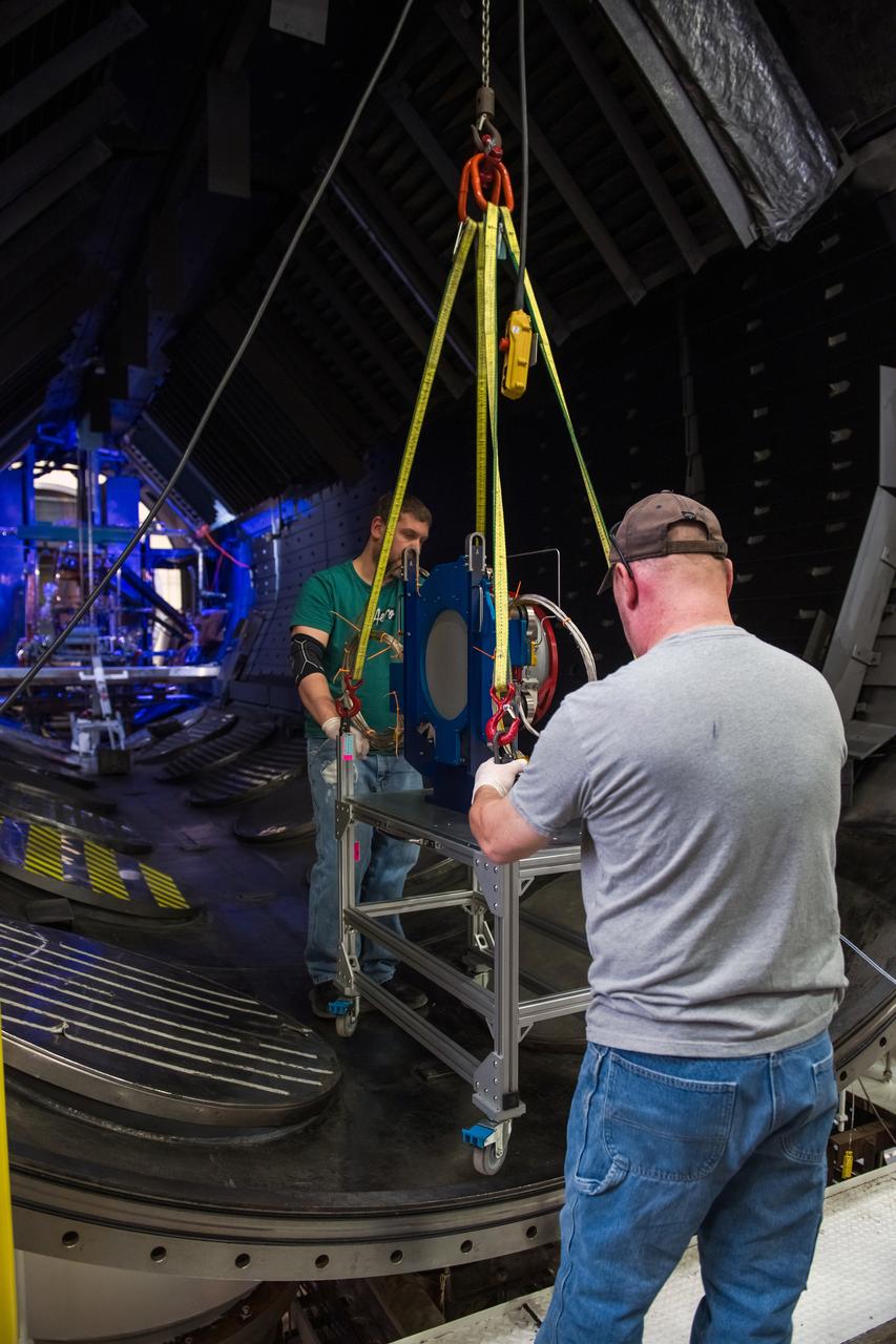
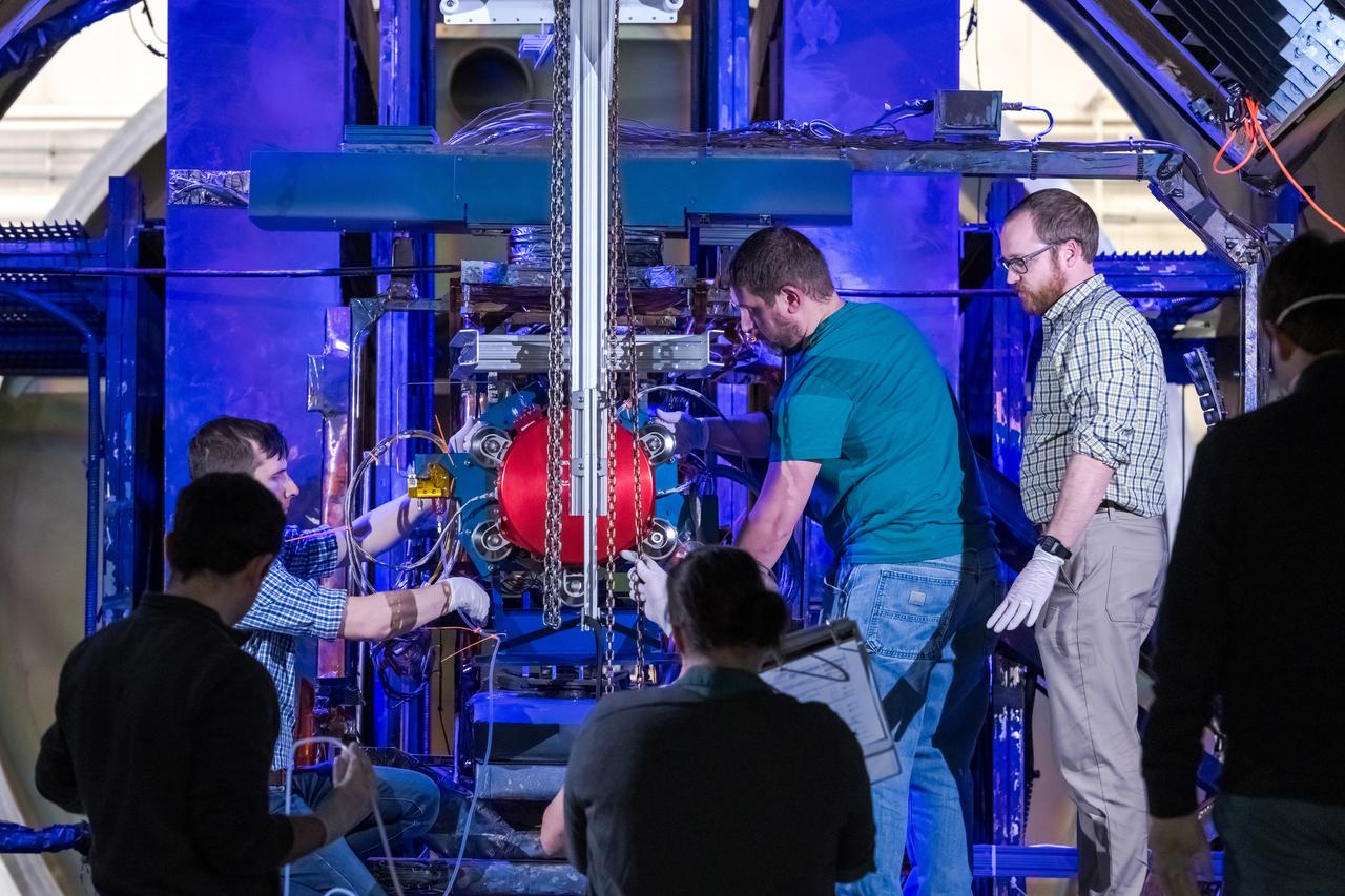
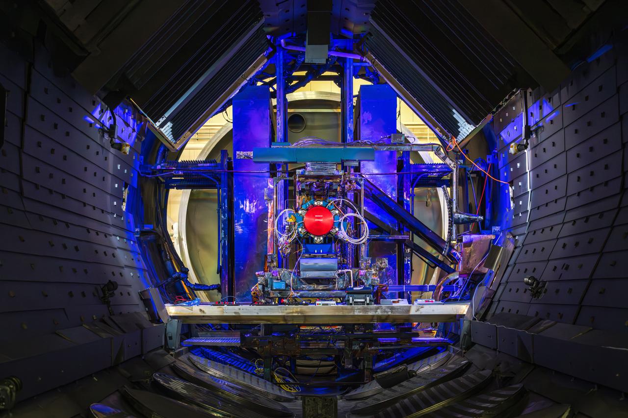
Set up of a Brayton Cycle Power System test in the Space Power Facility’s massive vacuum chamber at the National Aeronautics and Space Administration’s (NASA) Plum Brook Station in Sandusky, Ohio. The $28.4-million facility, which began operations in 1969, is the largest high vacuum chamber ever built. The chamber is 100 feet in diameter and 120 feet high. It can produce a vacuum deep enough to simulate the conditions at 300 miles altitude. The Space Power Facility was originally designed to test nuclear-power sources for spacecraft, but it was never used for that purpose. The Space Power Facility was first used to test a 15 to 20-kilowatt Brayton Cycle Power System for space applications. Three different methods of simulating solar heat were employed during the tests. Lewis researchers studied the Brayton power system extensively in the 1960s and 1970s. The Brayton engine converted solar thermal energy into electrical power. The system operated on a closed-loop Brayton thermodynamic cycle with a helium-xenon gas mixture as its working fluid. A space radiator was designed to serve as the system’s waste heat rejecter. The radiator was later installed in the vacuum chamber and tested in a simulated space environment to determine its effect on the power conversion system. The Brayton system was subjected to simulated orbits with 62 minutes of sun and 34 minutes of shade.
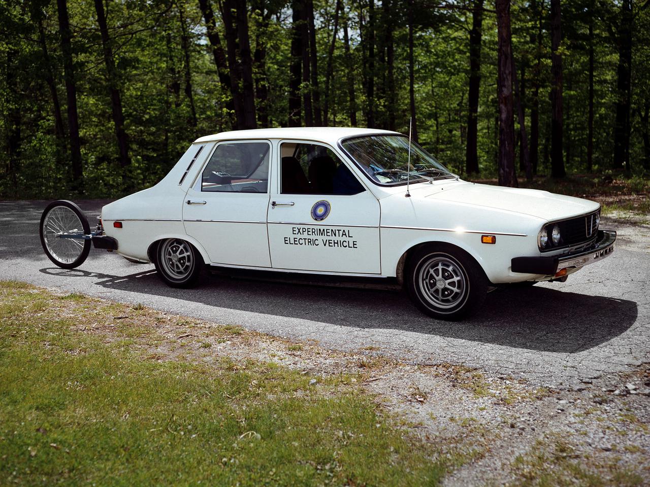
The National Aeronautics and Space Administration (NASA) Lewis Research Center tested 16 commercially-manufactured electric vehicles, including this Metro, during the mid-1970s. Lewis and the Energy Research and Development Administration (ERDA) engaged in several energy-related programs in the mid-1970s, including the Electric Vehicle Project. NASA and ERDA undertook the program in 1976 to determine the state of the current electric vehicle technology. As part of the project, Lewis and ERDA tested every commercially available electric car model. Electric Vehicle Associates, located in a Cleveland suburb, modified a Renault 12 vehicle to create this Metro. Its 1040-pound golfcart-type battery provided approximately 106 minutes of operation. The tests analyzed the vehicle’s range, acceleration, coast-down, braking, and energy consumption. Some of the vehicles had analog data recording systems to measure the battery during operation and sensors to determine speed and distance. The researchers found the performance of the different vehicles varied significantly. In general, the range, acceleration, and speed were lower than that found on conventional vehicles. They also found that traditional gasoline-powered vehicles were as efficient as the electric vehicles. The researchers concluded, however, that advances in battery technology and electric drive systems would significantly improve efficiency and performance.

KENNEDY SPACE CENTER, FLA. - In the Space Station Processing Facility, astronaut Tracy Caldwell (left) assists a technician check out the Pump Flow Control Subsystem (PFCS) before it is installed on the upper deck of the S6 Truss. The PFCS pumps and controls the liquid ammonia used to cool the various Orbital Replacement Units on the Integrated Equipment Assembly that make up the S6 Photo-Voltaic Power Module on the International Space Station (ISS). The fourth starboard truss segment, the S6 Truss measures 112 feet long by 39 feet wide. The solar arrays are mounted on a “blanket” that can be folded like an accordion for delivery to the ISS. Once in orbit, astronauts will deploy the blankets to their full size. When completed, the Station's electrical power system (EPS) will use eight photovoltaic solar arrays to convert sunlight to electricity. Delivery of the S6 Truss, the last power module truss segment, is targeted for mission STS-119.

KENNEDY SPACE CENTER, FLA. - In the Space Station Processing Facility, astronaut Tracy Caldwell (second from left) assists technicians lower the Pump Flow Control Subsystem (PFCS) into position onto the upper deck of the S6 Truss. The PFCS pumps and controls the liquid ammonia used to cool the various Orbital Replacement Units on the Integrated Equipment Assembly that make up the S6 Photo-Voltaic Power Module on the International Space Station (ISS). The fourth starboard truss segment, the S6 Truss measures 112 feet long by 39 feet wide. Its solar arrays are mounted on a “blanket” that can be folded like an accordion for delivery to the ISS. Once in orbit, astronauts will deploy the blankets to their full size. When completed, the Station's electrical power system (EPS) will use eight photovoltaic solar arrays to convert sunlight to electricity. Delivery of the S6 Truss, the last power module truss segment, is targeted for mission STS-119.
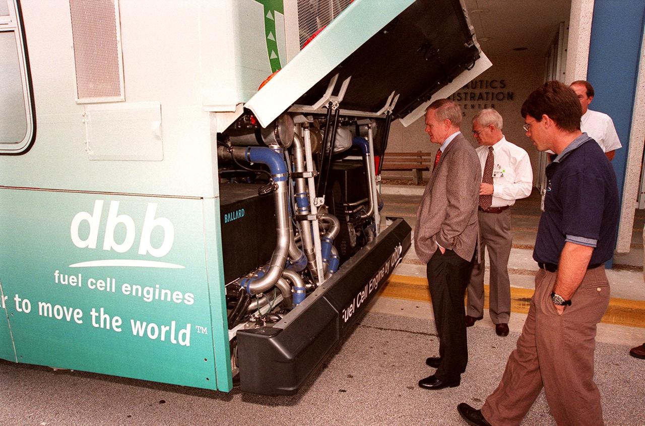
In front of the Headquarters Building at KSC, Center Director Roy Bridges (left) looks at the hydrogen-oxygen driven engine powering a Zero Emissions (ZE) transit bus. Provided by dbb fuel cell engines inc. of Vancouver, Canada, the ZE bus was brought to KSC as part of the Center's Alternative Fuel Initiatives Program. The bus uses a Proton Exchange Membrane fuel cell in which hydrogen and oxygen, from atmospheric air, react to produce electricity that powers an electric motor drive system. The by-product "exhaust" from the fuel cell is water vapor, thus zero harmful emissions. A typical diesel-powered bus emits more than a ton of harmful pollutants from its exhaust every year. Available for viewing by employees, the ZE bus is also being used on tour routes at the KSC Visitor Complex Oct. 26-27
KENNEDY SPACE CENTER, FLA. - Technicians attach a crane to the Pump Flow Control Subsystem (PFCS) in the Space Station Processing Facility. The PFCS pumps and controls the liquid ammonia used to cool the various Orbital Replacement Units on the Integrated Equipment Assembly that make up the S6 Photo-Voltaic Power Module on the International Space Station (ISS). The fourth starboard truss segment, the S6 Truss measures 112 feet long by 39 feet wide. Its solar arrays are mounted on a “blanket” that can be folded like an accordion for delivery to the ISS. Once in orbit, astronauts will deploy the blankets to their full size. When completed, the Station's electrical power system (EPS) will use eight photovoltaic solar arrays to convert sunlight to electricity. Delivery of the S6 Truss, the last power module truss segment, is targeted for mission STS-119.
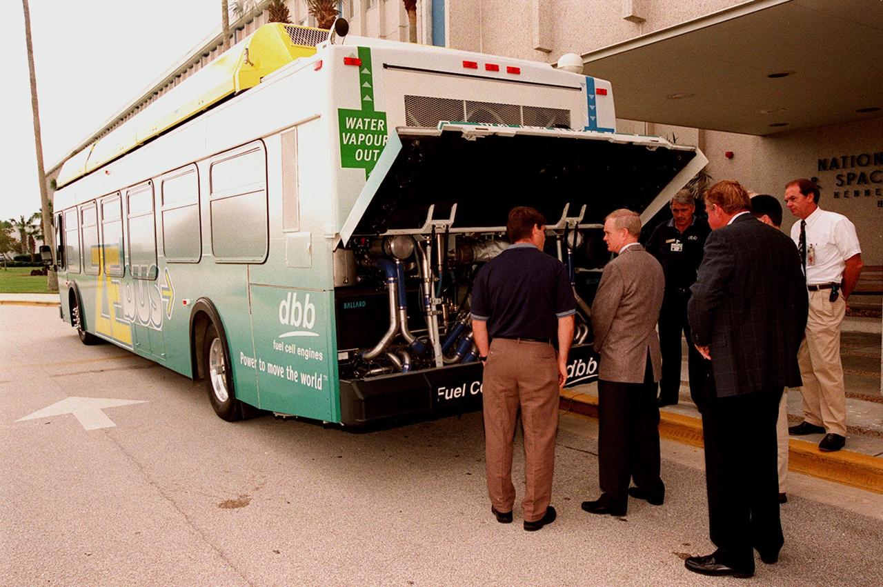
KSC employees, along with Center Director Roy Bridges (second from left), view the hydrogen-oxygen driven engine powering a Zero Emissions (ZE) transit bus. Provided by dbb fuel cell engines inc. of Vancouver, Canada, the ZE bus was brought to KSC as part of the Center's Alternative Fuel Initiatives Program. The bus uses a Proton Exchange Membrane fuel cell in which hydrogen and oxygen, from atmospheric air, react to produce electricity that powers an electric motor drive system. The by-product "exhaust" from the fuel cell is water vapor, thus zero harmful emissions. A typical diesel-powered bus emits more than a ton of harmful pollutants from its exhaust every year. Available for viewing by employees, the ZE bus is also being used on tour routes at the KSC Visitor Complex Oct. 26-27
KENNEDY SPACE CENTER, FLA. - In the Space Station Processing Facility, astronaut Tracy Caldwell (second from left) assists technicians position the Pump Flow Control Subsystem (PFCS) over the upper deck of the S6 Truss. The PFCS pumps and controls the liquid ammonia used to cool the various Orbital Replacement Units on the Integrated Equipment Assembly that make up the S6 Photo-Voltaic Power Module on the International Space Station (ISS). The fourth starboard truss segment, the S6 Truss measures 112 feet long by 39 feet wide. Its solar arrays are mounted on a “blanket” that can be folded like an accordion for delivery to the ISS. Once in orbit, astronauts will deploy the blankets to their full size. When completed, the Station's electrical power system (EPS) will use eight photovoltaic solar arrays to convert sunlight to electricity. Delivery of the S6 Truss, the last power module truss segment, is targeted for mission STS-119.
KENNEDY SPACE CENTER, FLA. - In the Space Station Processing Facility, astronaut Tracy Caldwell (left) assists technicians install the Pump Flow Control Subsystem (PFCS) onto the upper deck of the S6 Truss. The PFCS pumps and controls the liquid ammonia used to cool the various Orbital Replacement Units on the Integrated Equipment Assembly that make up the S6 Photo-Voltaic Power Module on the International Space Station (ISS). The fourth starboard truss segment, the S6 Truss measures 112 feet long by 39 feet wide. Its solar arrays are mounted on a “blanket” that can be folded like an accordion for delivery to the ISS. Once in orbit, astronauts will deploy the blankets to their full size. When completed, the Station's electrical power system (EPS) will use eight photovoltaic solar arrays to convert sunlight to electricity. Delivery of the S6 Truss, the last power module truss segment, is targeted for mission STS-119.
KENNEDY SPACE CENTER, FLA. - In the Space Station Processing Facility, a technician steadies the Pump Flow Control Subsystem (PFCS) as it is lifted and moved toward the S6 Truss. The PFCS pumps and controls the liquid ammonia used to cool the various Orbital Replacement Units on the Integrated Equipment Assembly that make up the S6 Photo-Voltaic Power Module on the International Space Station (ISS). The fourth starboard truss segment, the S6 Truss measures 112 feet long by 39 feet wide. Its solar arrays are mounted on a “blanket” that can be folded like an accordion for delivery to the ISS. Once in orbit, astronauts will deploy the blankets to their full size. When completed, the Station's electrical power system (EPS) will use eight photovoltaic solar arrays to convert sunlight to electricity. Delivery of the S6 Truss, the last power module truss segment, is targeted for mission STS-119.
KENNEDY SPACE CENTER, FLA. - Unpacking of the Pump Flow Control Subsystem (PFCS) begins in the Space Station Processing Facility. The PFCS pumps and controls the liquid ammonia used to cool the various Orbital Replacement Units on the Integrated Equipment Assembly that make up the S6 Photo-Voltaic Power Module on the International Space Station (ISS). The fourth starboard truss segment, the S6 Truss measures 112 feet long by 39 feet wide. Its solar arrays are mounted on a “blanket” that can be folded like an accordion for delivery to the ISS. Once in orbit, astronauts will deploy the blankets to their full size. When completed, the Station's electrical power system will use eight photovoltaic solar arrays to convert sunlight to electricity. Delivery of the S6 Truss, the last power module truss segment, is targeted for mission STS-119.
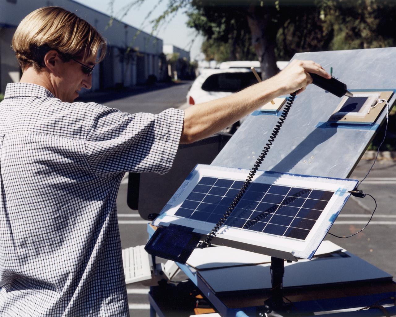
A technician at AeroVironment's Design Development Center in Simi Valley, California, checks a panel of silicon solar cells for conductivity and voltage. The bi-facial cells, fabricated by SunPower, Inc., of Sunnyvale, California, are among 64,000 solar cells which have been installed on the Helios Prototype solar-powered aircraft to provide power to its 14 electric motors and operating systems.
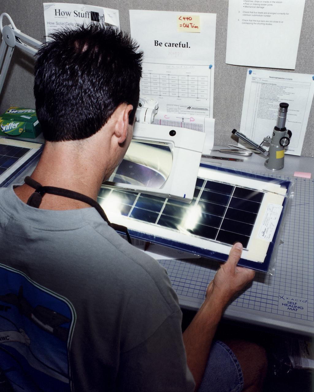
An engineer at AeroVironment's Design Development Center in Simi Valley, California, closely inspects a set of silicon solar cells for potential defects. The cells, fabricated by SunPower, Inc., of Sunnyvale, California, are among 64,000 solar cells which have been installed on the Helios Prototype solar-powered aircraft to provide power to its 14 electric motors and operating systems.
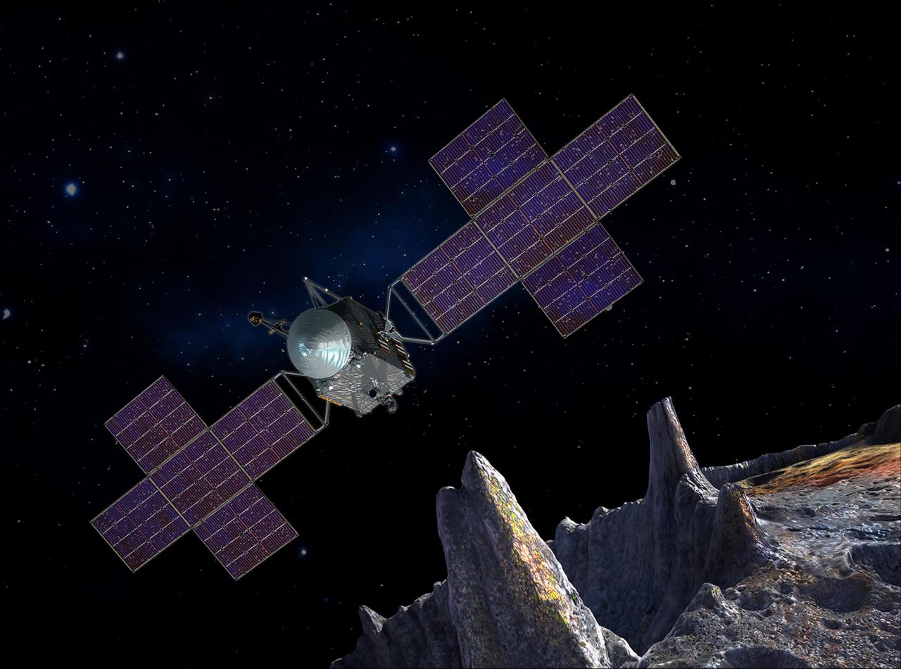
This artist's-concept illustration depicts the spacecraft of NASA's Psyche mission near the mission's target, the metal asteroid Psyche. The artwork was created in May 2017 to show the five-panel solar arrays planned for the spacecraft. The spacecraft's structure will include power and propulsion systems to travel to, and orbit, the asteroid. These systems will combine solar power with electric propulsion to carry the scientific instruments used to study the asteroid through space. The mission plans launch in 2022 and arrival at Psyche, between the orbits of Mars and Jupiter, in 2026. This selected asteroid is made almost entirely of nickel-iron metal. It offers evidence about violent collisions that created Earth and other terrestrial planets. https://photojournal.jpl.nasa.gov/catalog/PIA21499
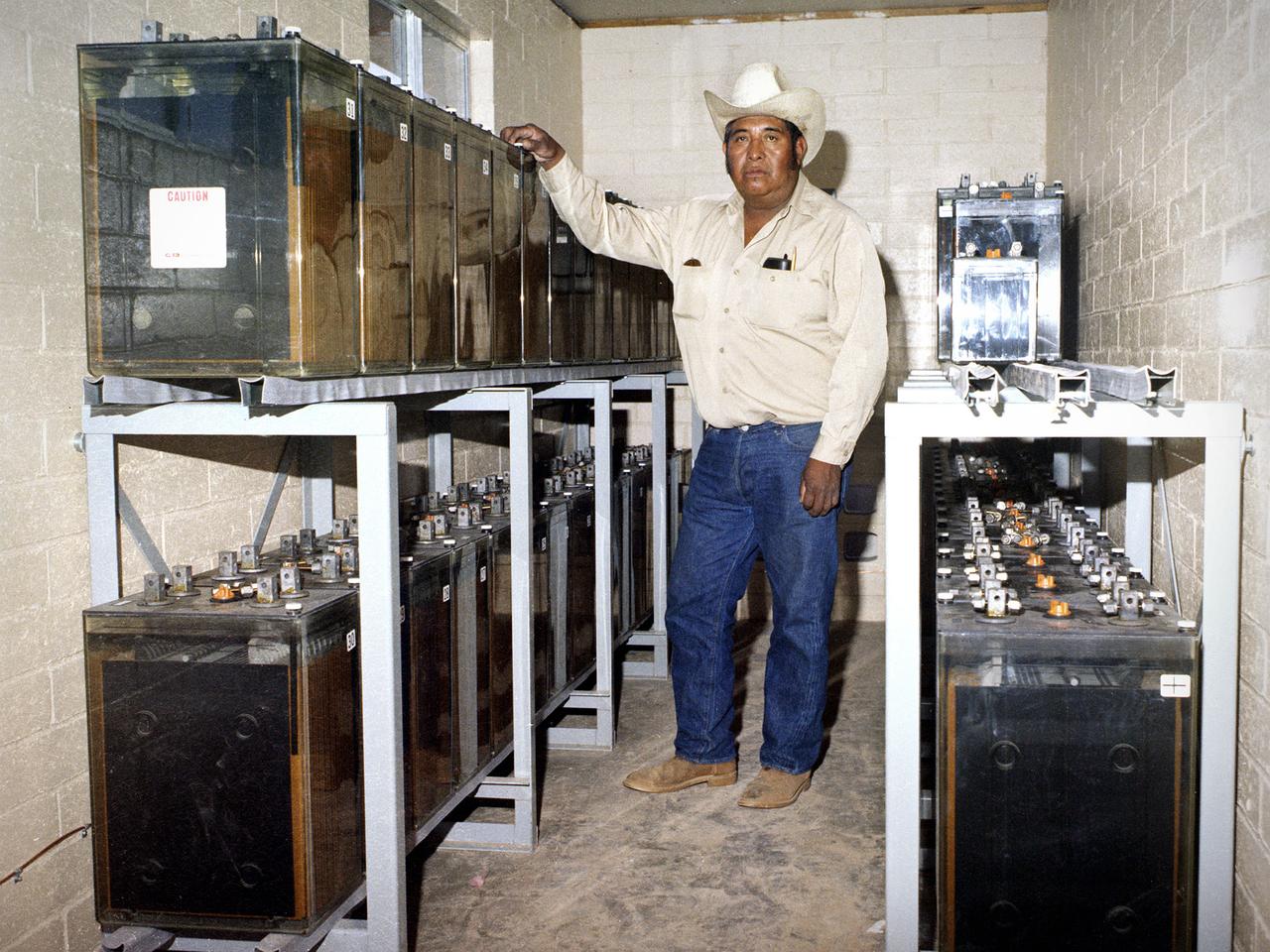
National Aeronautics and Space Administration (NASA) Lewis Research Center. NASA signed an agreement with the Papago tribe in May 1978 to provide the village with solar-generated electricity within the year. The project was funded by the Department of Energy and managed by NASA Lewis. Lewis provided all of the equipment and technical assistance while the tribe’s construction team built the arrays and support equipment, seen here. The 3.5-kilowatt system was modest in scope, but resulted in the first solar electric village. The system provided power to operate a refrigerator, freezer, washing machine, and water pump for the village and lights in each of the 16 homes. The system was activated on December 16, 1978. During the next year officials from around the world travelled to Schuchuli to ascertain if the system was applicable to their areas. The major television networks and over 100 publications covered the story. Less than one percent of the cells failed during the first year of operation.
KENNEDY SPACE CENTER, FLA. -- Working on the Orbiter Docking System of orbiter Atlantis are Mission Specialists Tom Jones (leaning over) and Robert Curbeam. They and the rest of the crew are at KSC for Crew Equipment Interface Test activities. Launch on mission STS-98 is scheduled for Jan. 18, 2001. It will be transporting the U.S. Lab, Destiny, to the International Space Station with five system racks already installed inside of the module. After delivery of electronics in the lab, electrically powered attitude control for Control Moment Gyroscopes will be activated