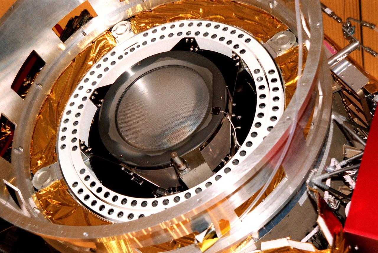
Kennedy Space Center, Florida. - Deep Space 1 is lifted from its work platform, giving a closeup view of the experimental solar-powered ion propulsion engine. The ion propulsion engine is the first non-chemical propulsion to be used as the primary means of propelling a spacecraft. The first flight in NASA's New Millennium Program, Deep Space 1 is designed to validate 12 new technologies for scientific space missions of the next century. Another onboard experiment includes software that tracks celestial bodies so the spacecraft can make its own navigation decisions without the intervention of ground controllers. Deep Space 1 will complete most of its mission objectives within the first two months, but may also do a flyby of a near-Earth asteroid, 1992 KD, in July 1999. Deep Space 1 will be launched aboard a Boeing Delta 7326 rocket from Launch Pad 17A, Cape Canaveral Air Station, in October. Delta II rockets are medium capacity expendable launch vehicles derived from the Delta family of rockets built and launched since 1960. Since then there have been more than 245 Delta launches. http://photojournal.jpl.nasa.gov/catalog/PIA04232
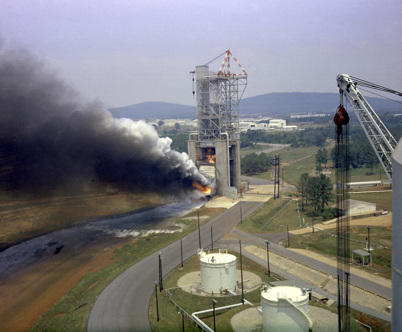
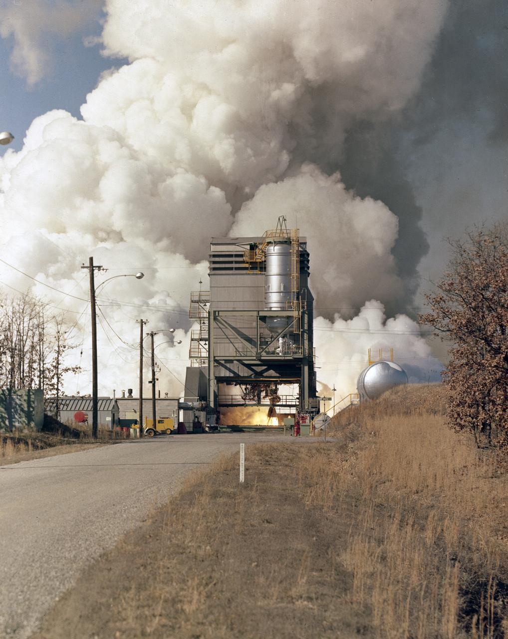
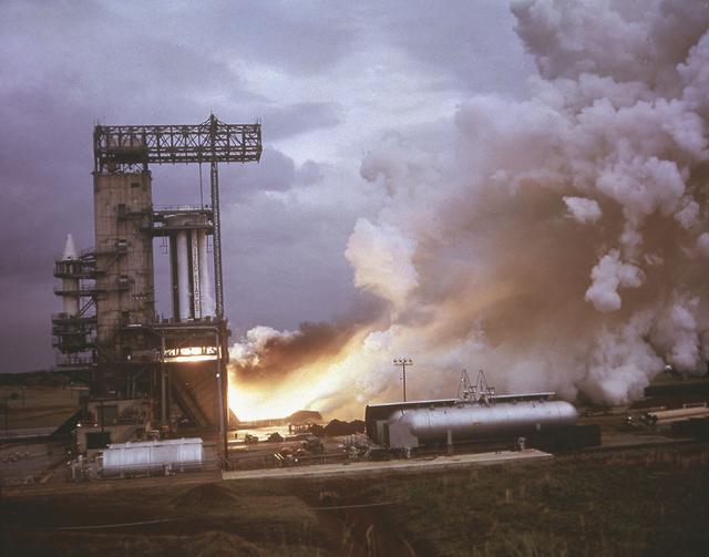
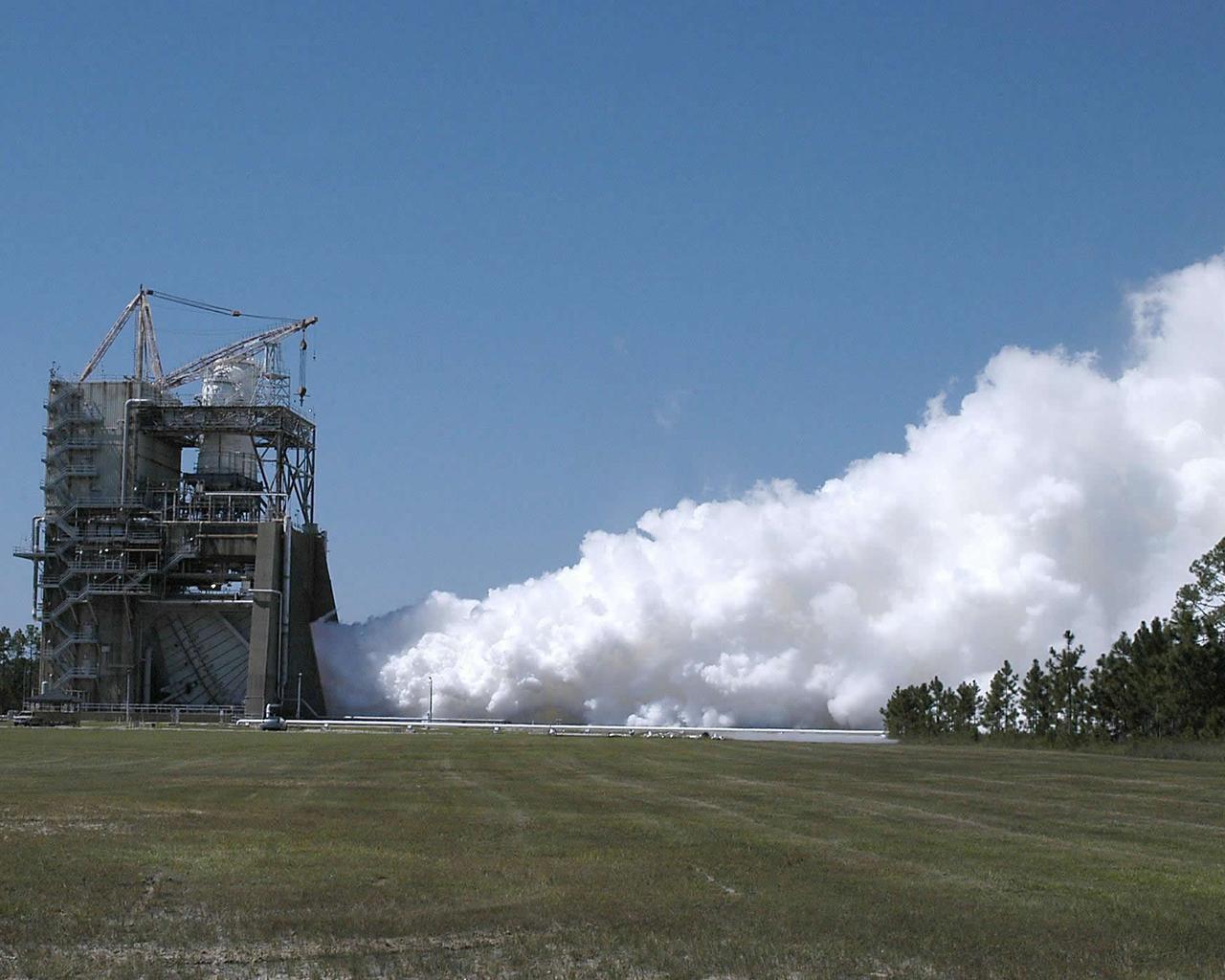
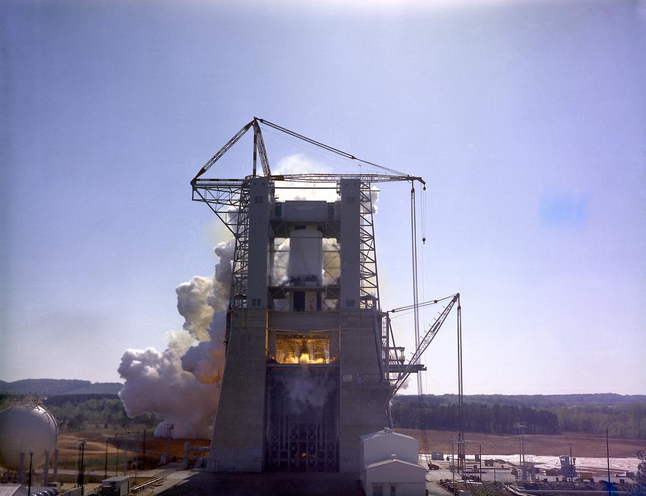
This photograph depicts a test firing of an F-1 engine at the F-1 engine test stand in the west test area of the Marshall Space Flight Center. This engine produced 1,500,000 pounds of thrust using liquid oxygen and RP-1, which is a derivative of kerosene. The F-1 engine test stand was constructed in 1963 to assist in the development of the F-1 engine.
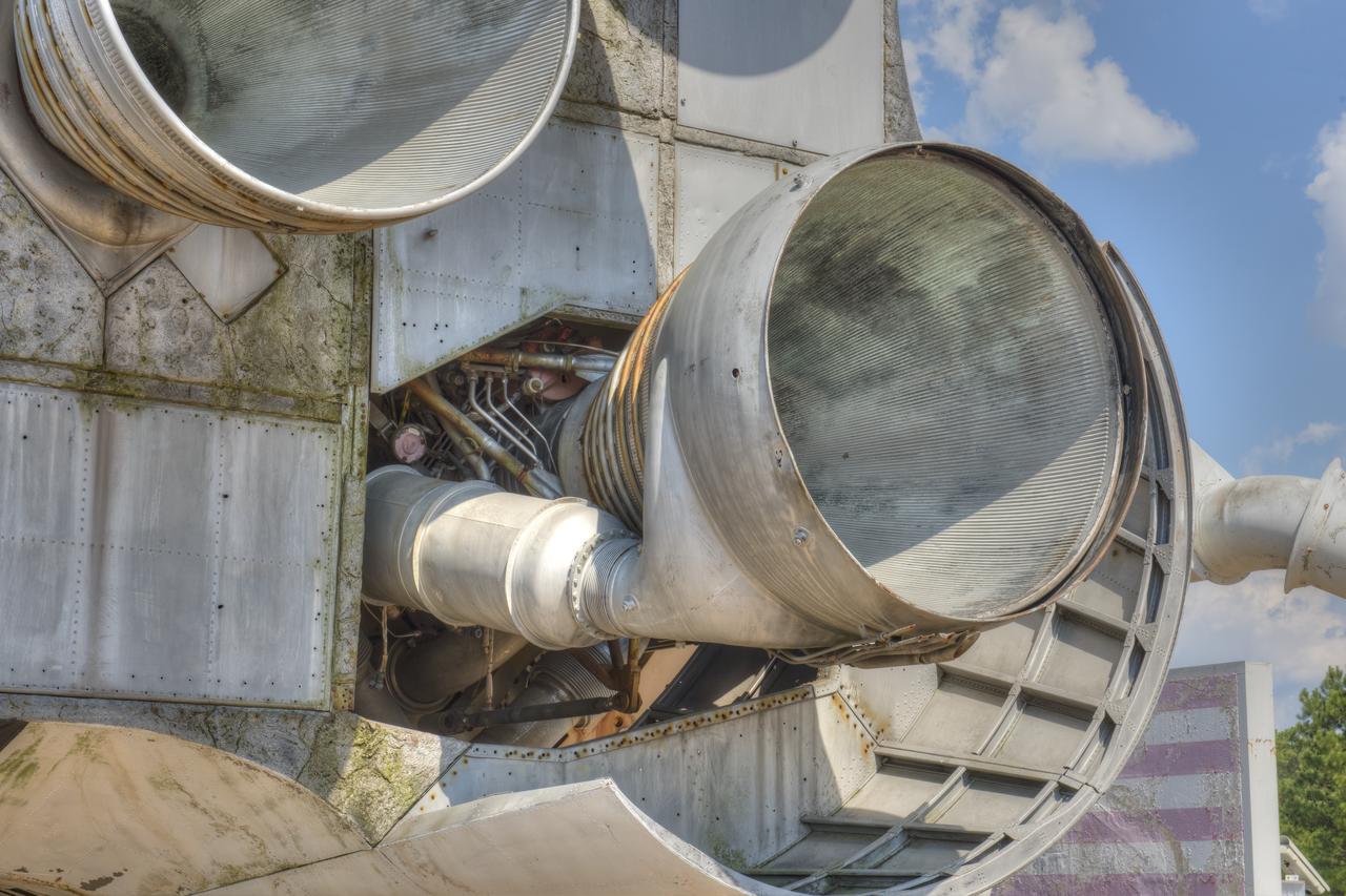
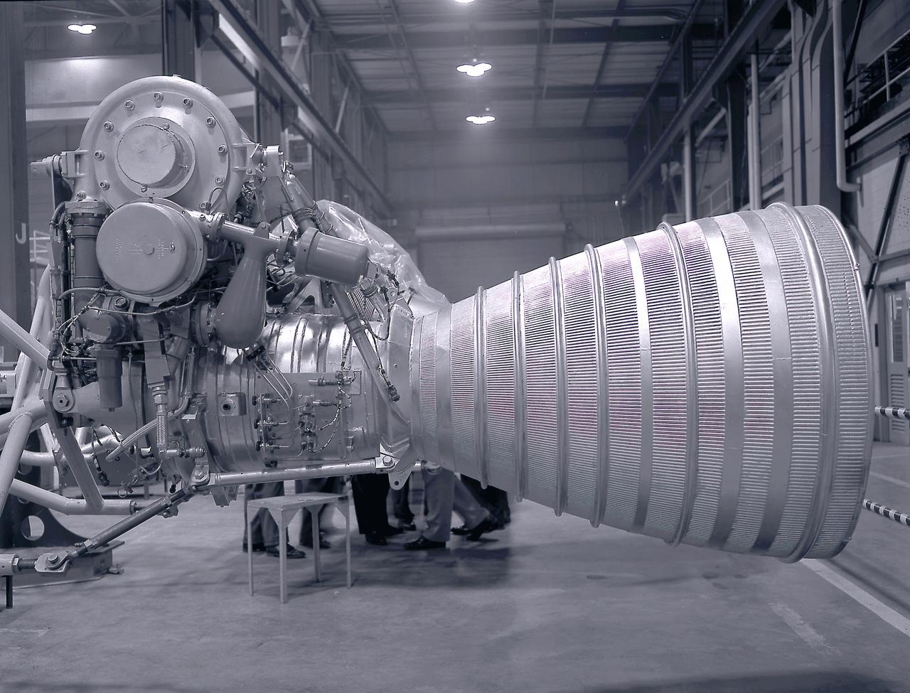
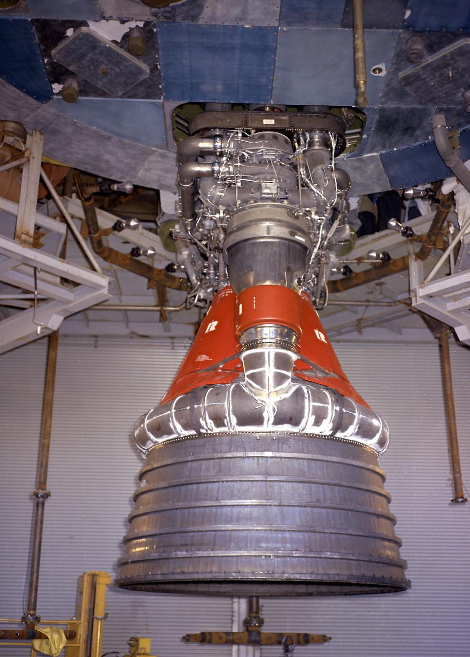
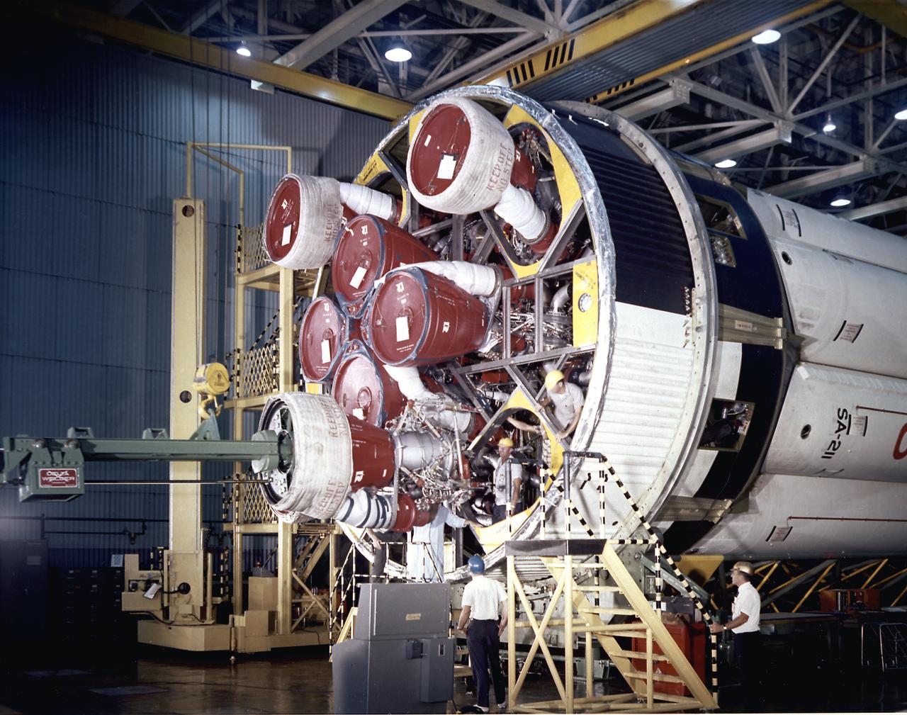
CLOSE-UP OF H-1 ENGINE INSTALLED ON SATURN S-1B STAGE (SA-T) NEAR PROPULSION AND STRUCTURAL TEST FACILITY (BUILDING 4572) AT THE GEORGE C. MARSHALL SPACE FLIGHT CENTER.
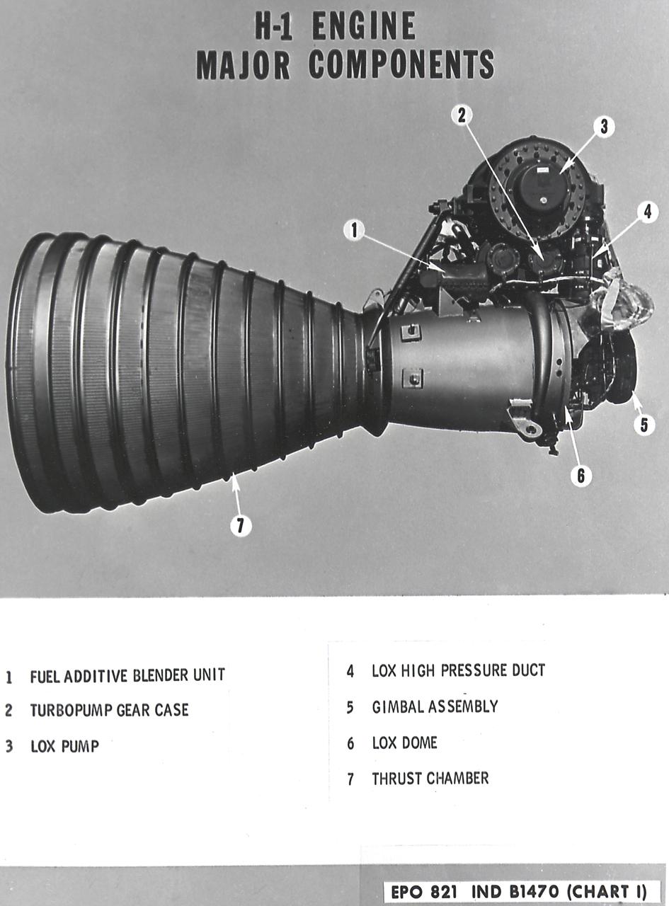
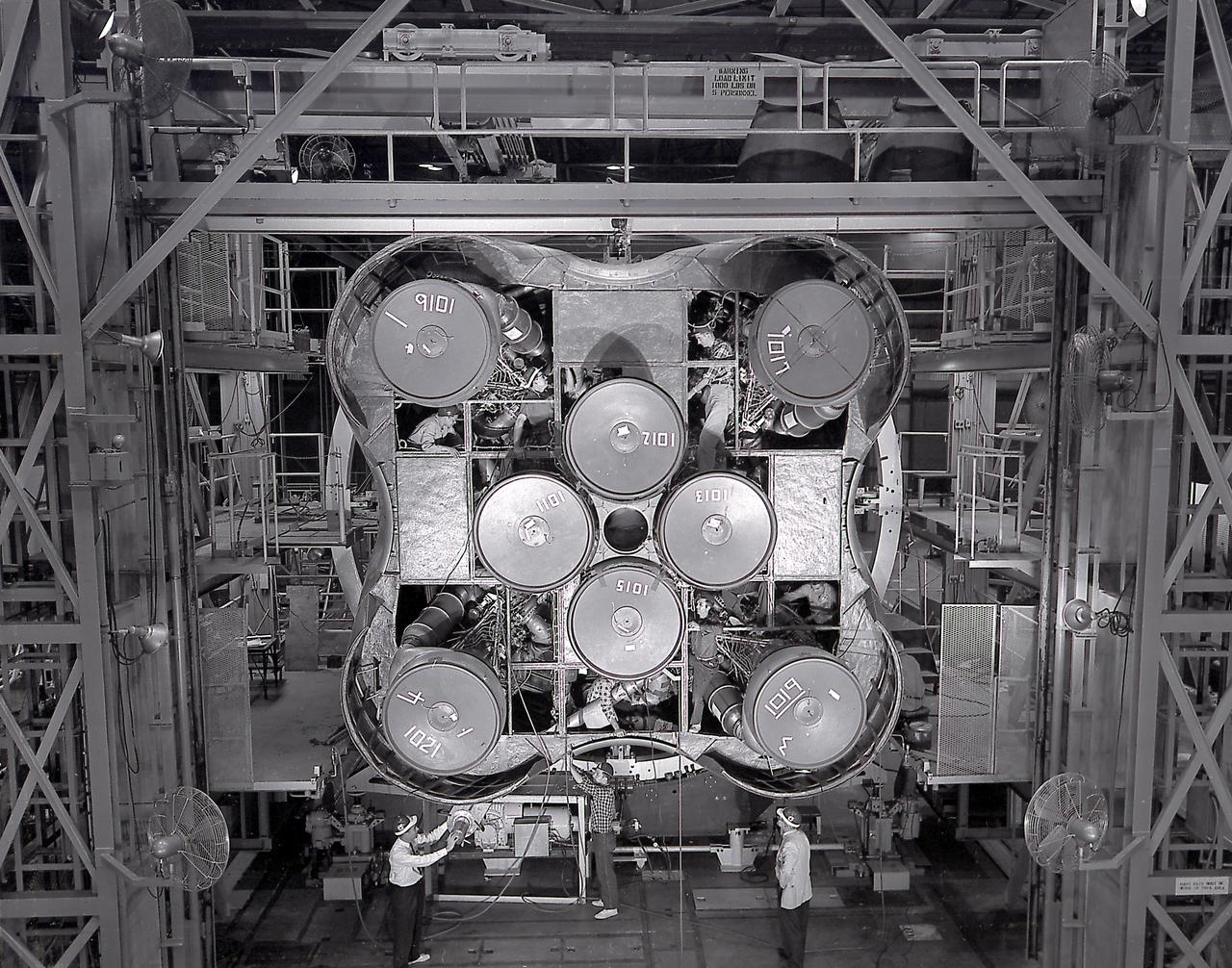
H-1 Engine major components with callouts (chart 1): The H-1 engine was used in a cluster of eight on the the first stage of Saturn I (S-I stage) and Saturn IB (S-IB stage). The engines were arranged in a double pattern: four engines, located inboard, were fixed in a square pattern around the stage axis, while the remaining four engines were located outboard in a larger square pattern and each outer engine was gimbaled. Each H-1 engine had a thrust of 188,000 pounds for a combined thrust of over 1,500,000 pounds.
Alignment of the H-1 engine performed in the Army Ballistic Missile Agency (ABMA ), building 4708, in February 1960. A cluster of eight H-1 engines were used to thrust the first stage of the Saturn I launch vehicle. The H-1 engine was developed under the direction of the Marshall Space Flight Center.
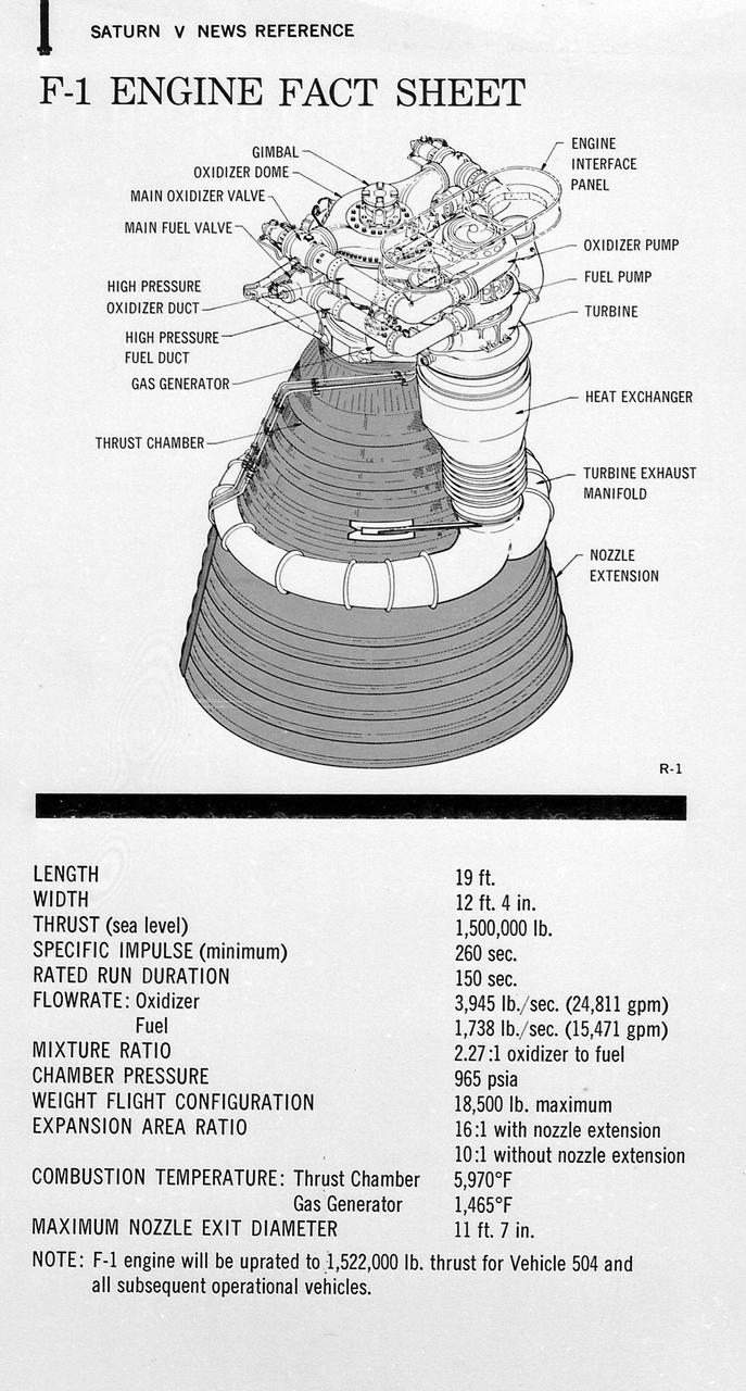
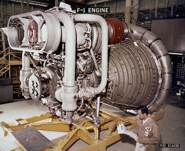
This figure is a drawing of the F-1 engine with callouts of the major components and the engine characteristics.
This chart provides the vital statistics for the F-1 rocket engine. Developed by Rocketdyne, under the direction of the Marshall Space Flight Center, the F-1 engine was utilized in a cluster of five engines to propel the Saturn V's first stage, the S-IC. Liquid oxygen and kerosene were used as its propellant. Initially rated at 1,500,000 pounds of thrust, the engine was later uprated to 1,522,000 pounds of thrust after the third Saturn V launch (Apollo 8, the first marned Saturn V mission) in December 1968. The cluster of five F-1 engines burned over 15 tons of propellant per second, during its two and one-half minutes of operation, to take the vehicle to a height of about 36 miles and to a speed of about 6,000 miles per hour.
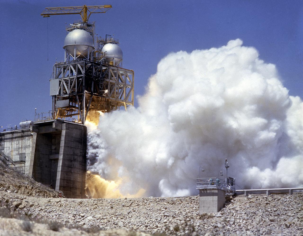
This photograph depicts the Rocketdyne static firing of the F-1 engine at the towering 76-meter Test Stand 1-C in Area 1-125 of the Edwards Air Force Base in California. The Saturn V S-IC (first) stage utilized five F-1 engines for its thrust. Each engine provided 1,500,000 pounds, for a combined thrust of 7,500,000 pounds with liquid oxygen and kerosene as its propellants.
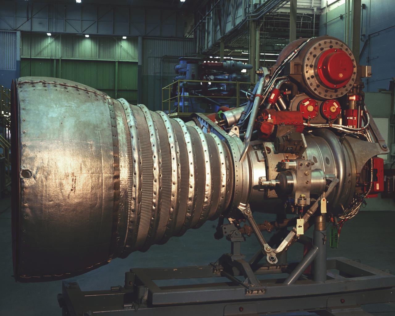
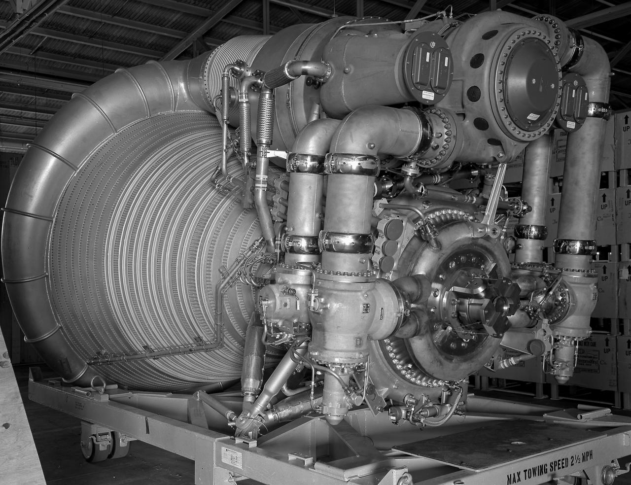
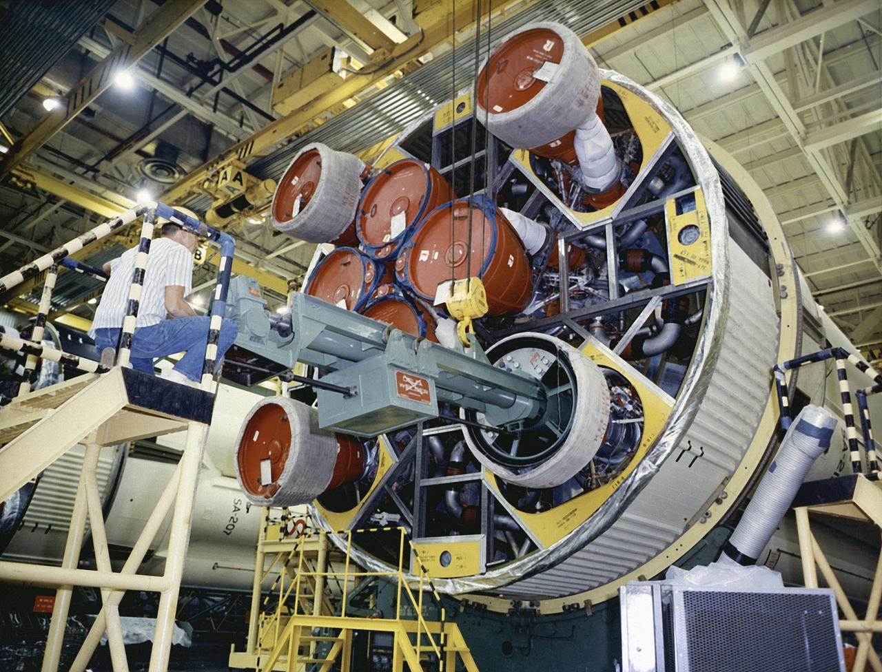
A cluster of eight H-1 engines were used to thrust the first stage of Saturn I (S-I stage) and Saturn IB (S-IB stage). The engines were arranged in a double pattern. Four engines, located inboard, were fixed in a square pattern around the stage axis, while the remaining four engines were located outboard in a larger square pattern and each outer engine was gimbaled. Each H-1 engine, fueled with liquid oxygen (LOX) and kerosene (RP-1), initially had a thrust of 188,000 pounds each for a combined thrust of over 1,500,000 pounds. Later, the H-1 engine was upgraded to 205,000 pounds of thrust and a combined total thrust of 1,650,000 pounds for the Saturn IB program. This photo depicts a single modified H-1 engine. The H-1 engine was developed under the direction of Marshall Space Flight Center (MSFC).
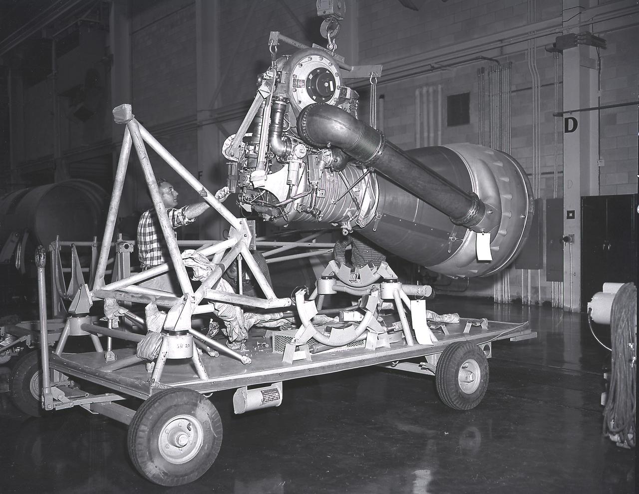
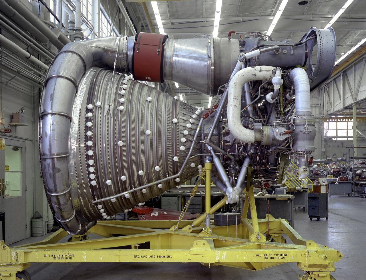
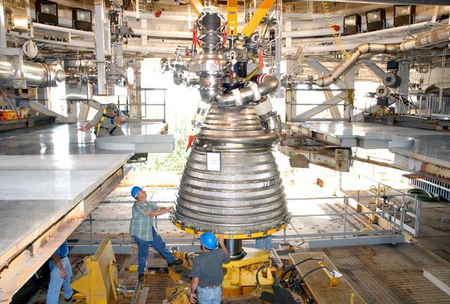
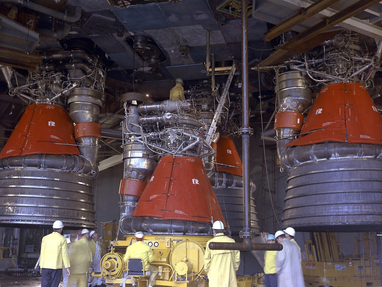
This close-up view of the F-1 engine for the Saturn V S-IC (first) stage shows the engine's complexity, and also its large size as it dwarfs the technician. Developed by Rocketdyne, under the direction of the Marshall Space Flight Center, the F-1 engine was utilized in a cluster of five engines to propel the Saturn V's first stage, the S-IC. Liquid oxygen and kerosene were used as its propellant. Initially rated at 1,500,000 pounds of thrust, the engine was later uprated to 1,522,000 pounds of thrust after the third Saturn V launch (Apollo 8, the first marned Saturn V mission) in December 1968. The cluster of five F-1 engines burned over 15 tons of propellant per second, during its two and one-half minutes of operation, to take the vehicle to a height of about 36 miles and to a speed of about 6,000 miles per hour.
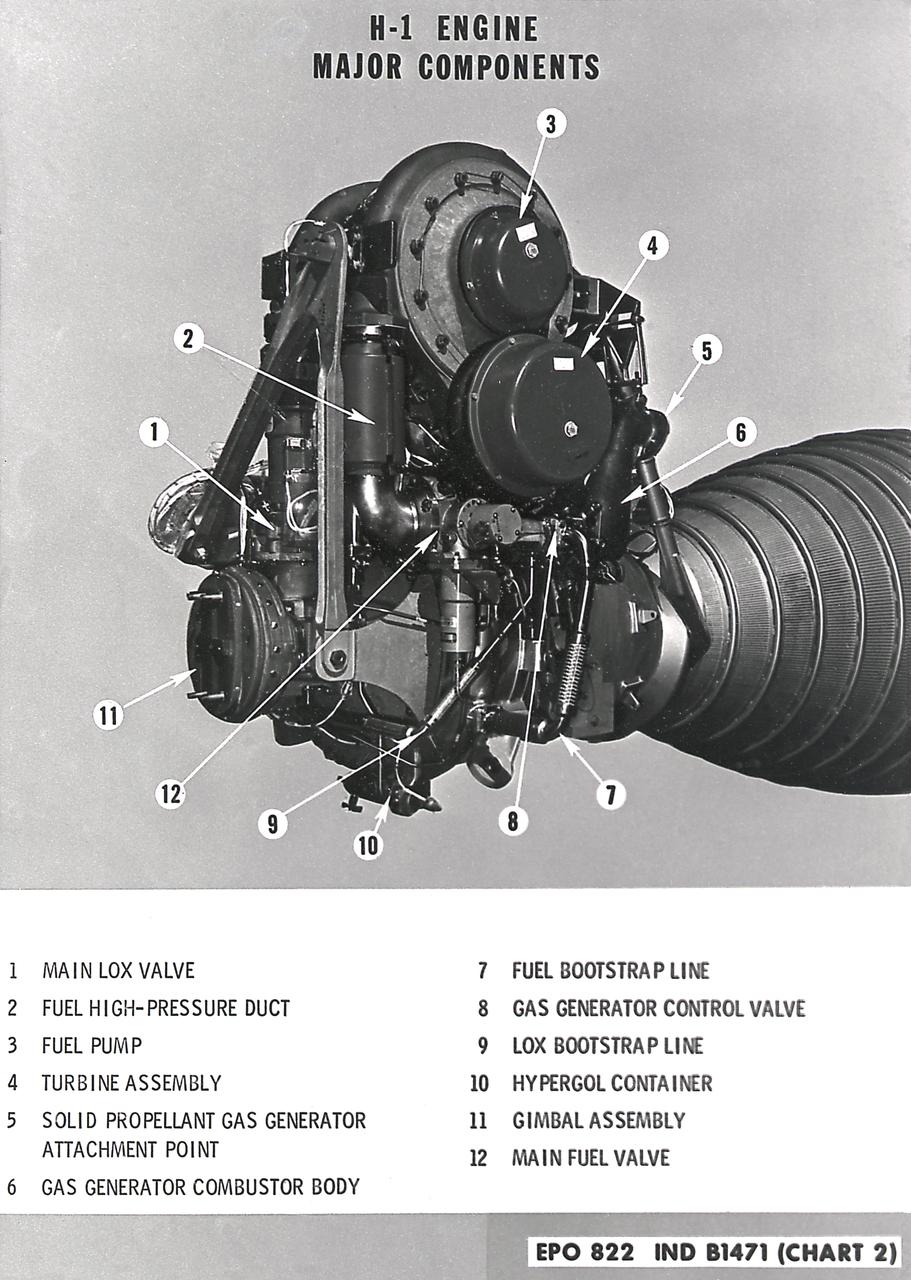
H-1 engine major components with callouts (chart 1). The H-1 engine was used in a cluster of eight on the the first stage of Saturn I (S-I stage) and Saturn IB (S-IB stage). The engines were arranged in a double pattern: four engines, located inboard, were fixed in a square pattern around the stage axis, while the remaining four engines were located outboard in a larger square pattern and each outer engine was gimbaled. Each H-1 engine had a thrust of 188,000 pounds for a combined thrust of over 1,500,000 pounds.
A Cluster of eight H-1 engines were used to thrust the first stage of Saturn I (S-I stage) and Saturn IB (S-IB stage). The engines were arranged in a double pattern. Four engines, located inboard, were fixed in a square pattern around the stage axis, while the remaining four engines were located outboard in a larger square pattern and each outer engine was gimbaled. The H-1 engine, fueled with liquid oxygen (LOX) and kerosene (RP-1), had a thrust of 188,000 pound each for a combined thrust of over 1,500,000 pounds. Each H-1 engine was developed under the direction of Marshall Space Flight Center (MSFC).
A close-up image of the single H-1 engine was test-fired at Canoga Park, California. Initial development of testing for the H-1 engine took place in the engineering facilities at Rocketdyne's main plant in Canoga Park, California.
In this photograph, the single H-1 engine was test-fired at Canoga Park, California. Initial development of testing for the H-1 engine took place in the engineering facilities at Rocketdyne's main plant in Canoga Park, California.
The static firing of a Saturn F-1 engine at the Marshall Space Flight Center's Static Test Stand. The F-1 engine is a single-start, 1,5000,000 Lb fixed-thrust, bipropellant rocket system. The engine uses liquid oxygen as the oxidizer and RP-1 (kerosene) as fuel. The five-engine cluster used on the first stage of the Saturn V produces 7,500,000 lbs of thrust.
Just two weeks after setting a record with a long-duration test of the J-2X rocket engine powerpack assembly, NASA engineers at Stennis Space Center exceeded it. On July 24, 2012, engineers surpassed the earlier 1,150-second record with a 1,350-second test of the engine component on the A-1 Test Stand at Stennis.
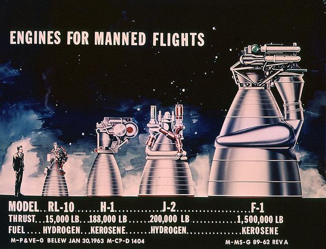
This drawing clearly shows the comparative sizes of the rocket engines used to launch the Saturn vehicles. The RL-10 and the H-1 engines were used to launch the Saturn I rockets. The J-2 engine was used on the second stage of Saturn IB and the second and third stages of Saturn V. The F-1 engine was used on the first stage of the Saturn V.
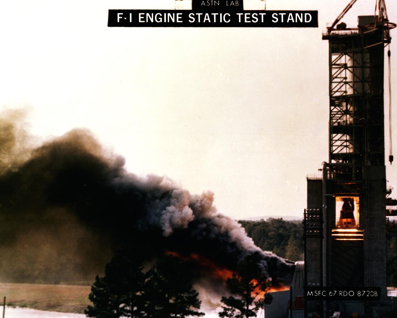
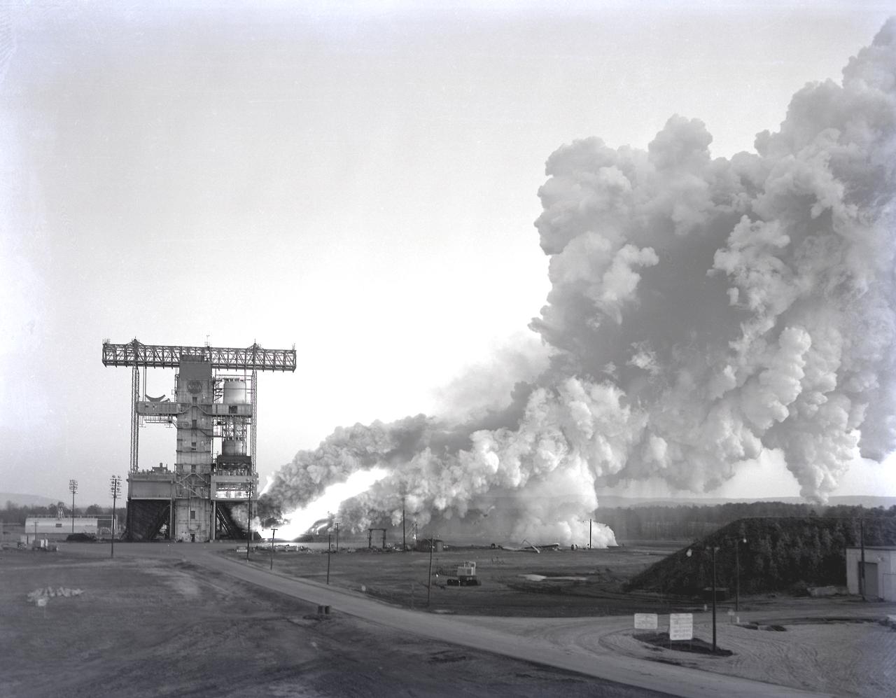
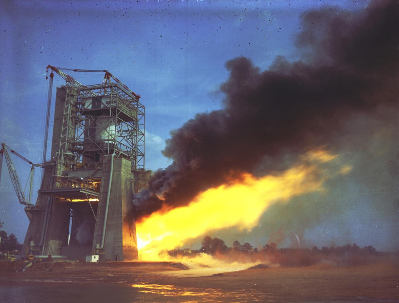
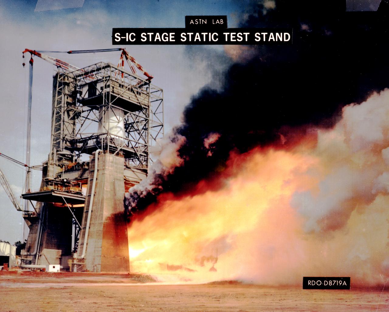
This photograph depicts the F-1 engine firing in the Marshall Space Flight Center’s F-1 Engine Static Test Stand. Construction of the S-IC Static test stand complex began in 1961 in the west test area of MSFC, and was completed in 1964. It is a vertical engine firing test stand, 239 feet in elevation and 4,600 square feet in area at the base, designed to assist in the development of the F-1 Engine. Capability is provided for static firing of 1.5 million pounds of thrust using liquid oxygen and kerosene. The foundation of the stand is keyed into the bedrock approximately 40 feet below grade.
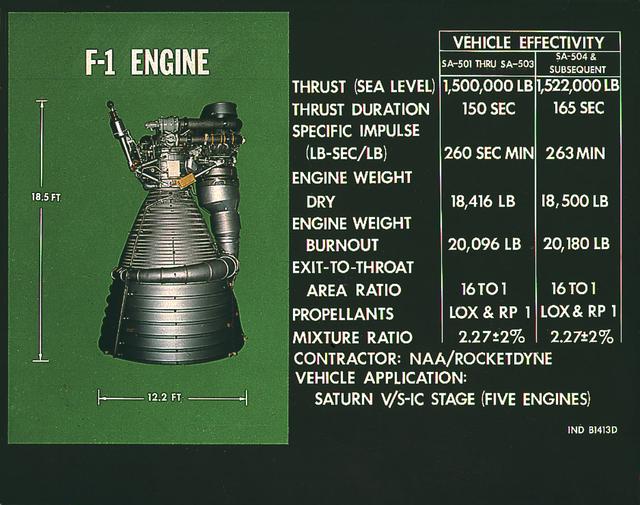
A complete F-1 engine assembly is shown in this photograph. Designed and developed by Rocketdye under the direction of the Marshall Space Flight Center, the engine measured 19-feet tall by 12.5 feet at the nozzle exit, and each engine produced a 1,500,000-pound thrust using liquid oxygen and kerosene as the propellant. A cluster of five F-1 engines was mounted on the Saturn V S-IC (first) stage and burned 15 tons of liquid oxygen and kerosene each second to produce 7,500,000 pounds of thrust.
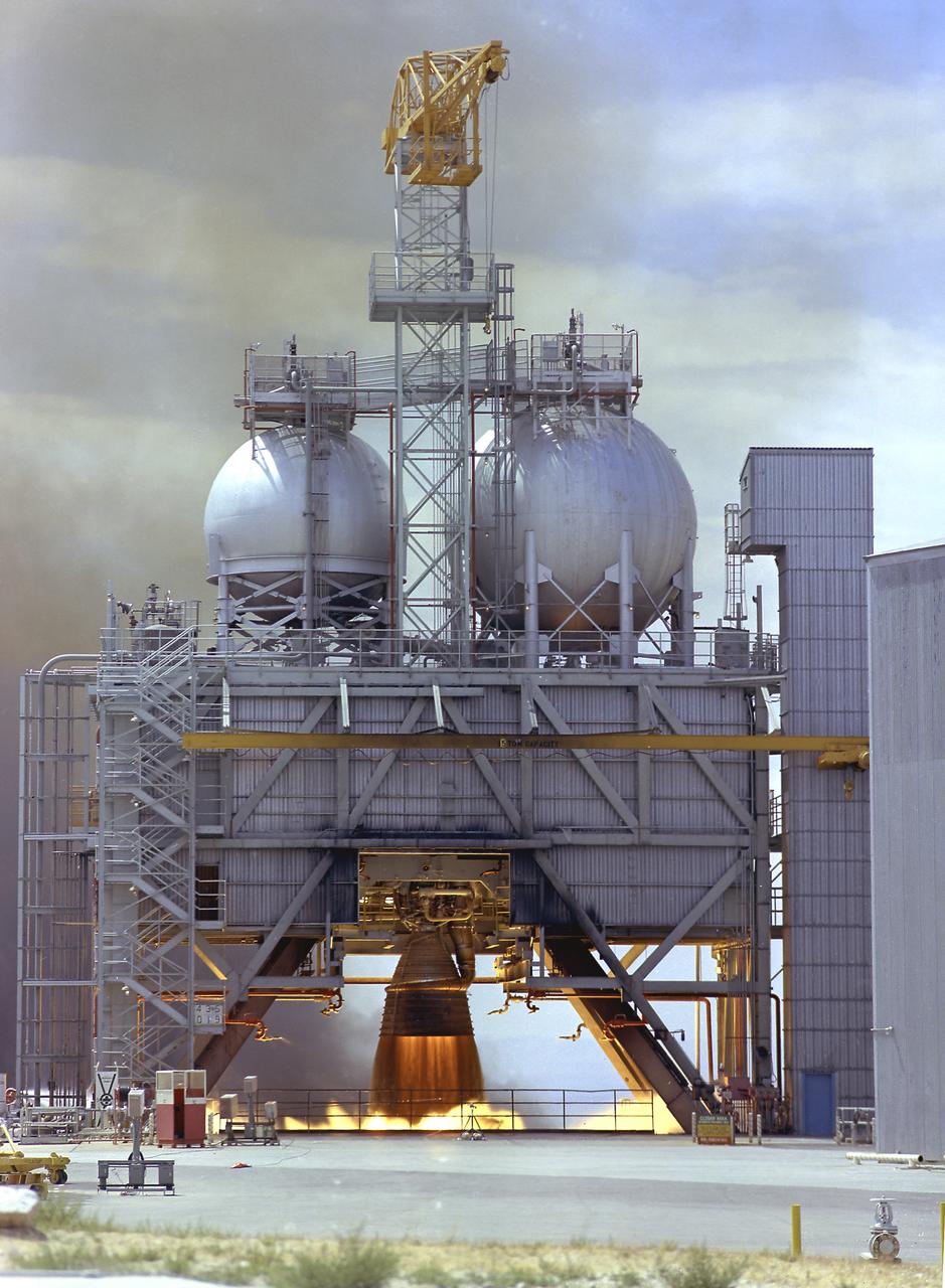
The F-1 engine was developed and built by Rocketdyne under the direction of the Marshall Space Flight Center. It measured 19 feet tall by 12.5 feet at the nozzle exit, and produced a 1,500,000-pound thrust using liquid oxygen and kerosene as the propellant. The image shows an F-1 engine being test fired at the Test Stand 1-C at the Edwards Air Force Base in California.
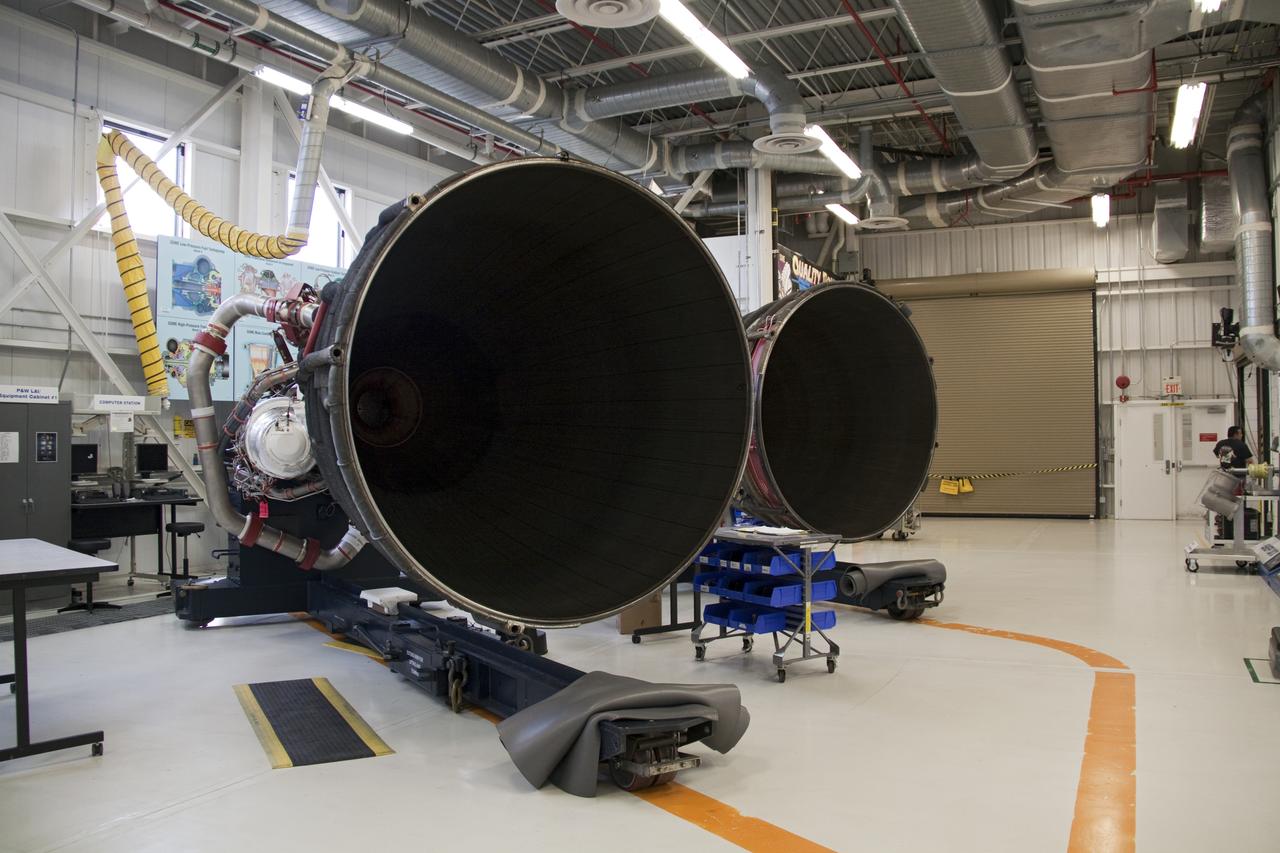
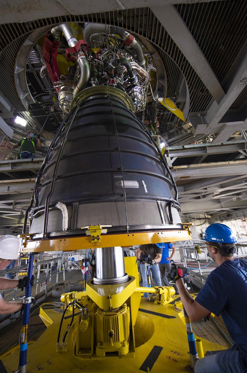
STS-132 ATLANTIS - ENGINE #2 LIFT TO TRANSPORTERAT ENGINE SHOP - XFER TO OPF-1 & INSTALL
STS-132 ATLANTIS - ENGINE #2 LIFT TO TRANSPORTERAT ENGINE SHOP - XFER TO OPF-1 & INSTALL
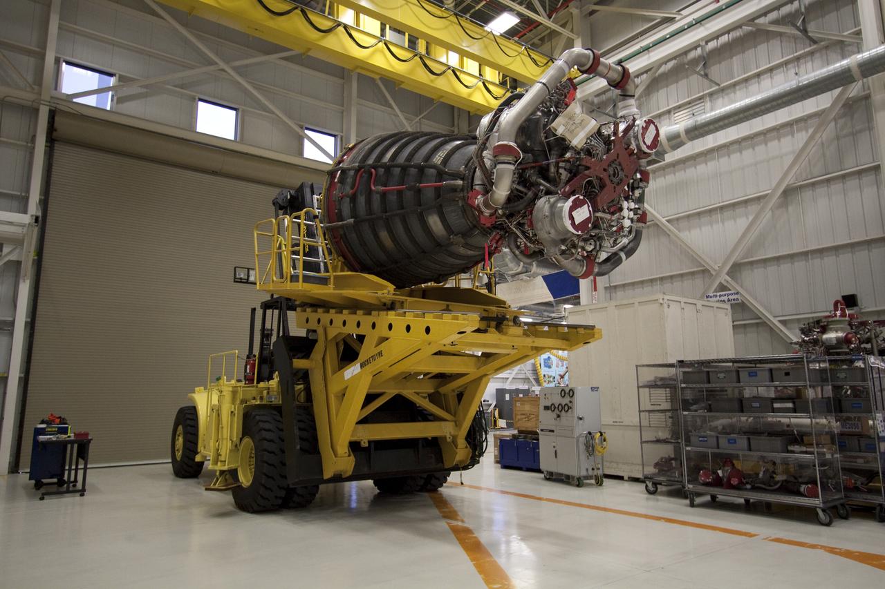
STS-132 ATLANTIS - ENGINE #2 LIFT TO TRANSPORTERAT ENGINE SHOP - XFER TO OPF-1 & INSTALL
STS-132 ATLANTIS - ENGINE #2 LIFT TO TRANSPORTERAT ENGINE SHOP - XFER TO OPF-1 & INSTALL
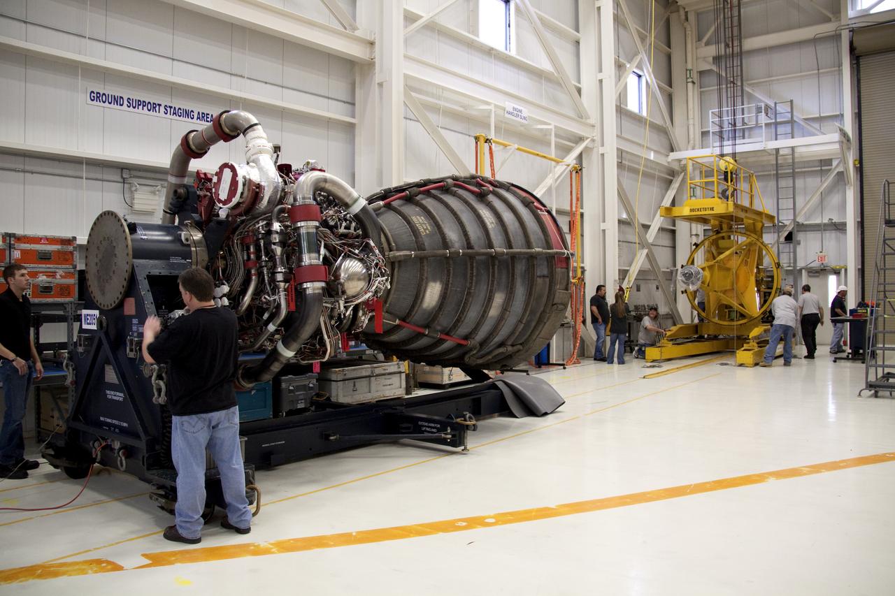
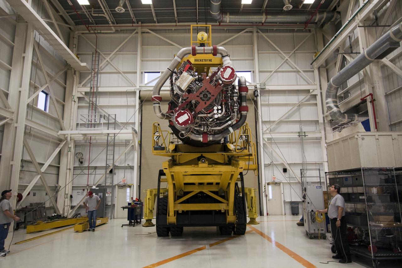
STS-132 ATLANTIS - ENGINE #2 LIFT TO TRANSPORTERAT ENGINE SHOP - XFER TO OPF-1 & INSTALL
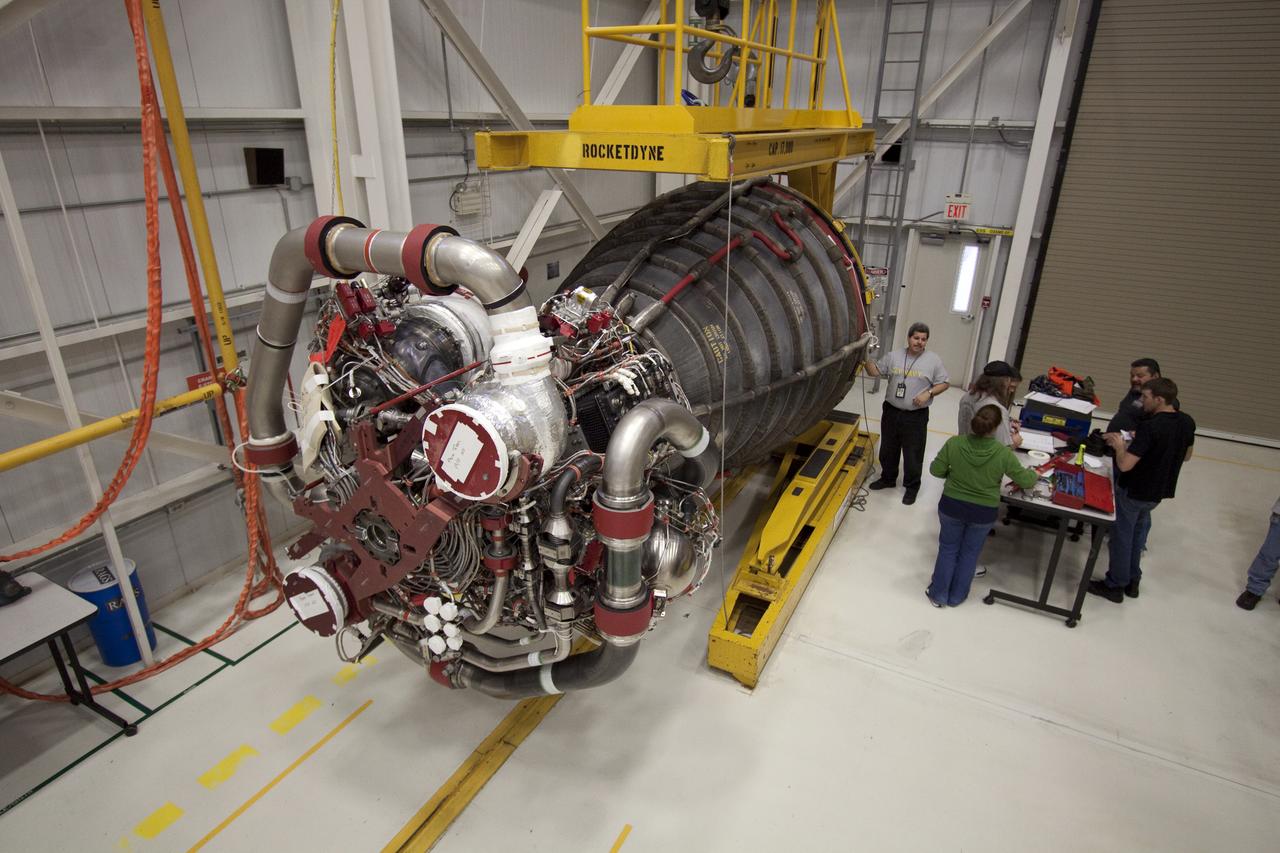
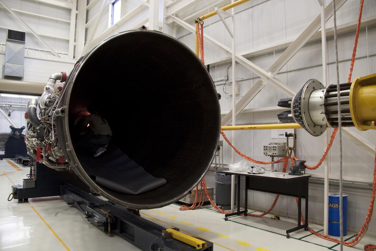
STS-132 ATLANTIS - ENGINE #2 LIFT TO TRANSPORTERAT ENGINE SHOP - XFER TO OPF-1 & INSTALL
The Saturn I S-I stage with eight H-1 engines, located in Marshall Space Flight Center building 4705, showing the positioning of eight H-1 engines. The Saturn I S-I stage had eight H-1 engines clustered, using liquid oxygen/kerosene-1 (LOX/RP-1) propellants capable of producing a total of 1,500,000 pounds of thrust.
Engineers at the Marshall Space Flight Center install the F-1 engines on the S-IC stage thrust structure at the S-IC static test stand. Engines are installed on the stage after it has been placed in the test stand. This image shows a close-up of an F-1 engine. Five F-1 engines, each weighing 10 tons, gave the booster a total thrust of 7,500,000 pounds, roughly equivalent to 160 million horsepower.
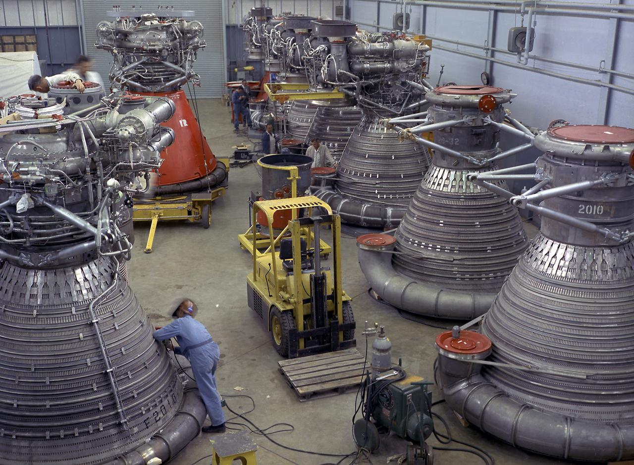
This photograph shows F-1 engines being stored in the F-1 Engine Preparation Shop, building 4666, at the Marshall Space Flight Center. Each F-1 engine produced a thrust of 1,500,000 pounds. A cluster of five engines was mounted on the thrust structure of the S-IC stage of a 364-foot long Saturn V launch vehicle that ultimately took astronauts to the Moon.
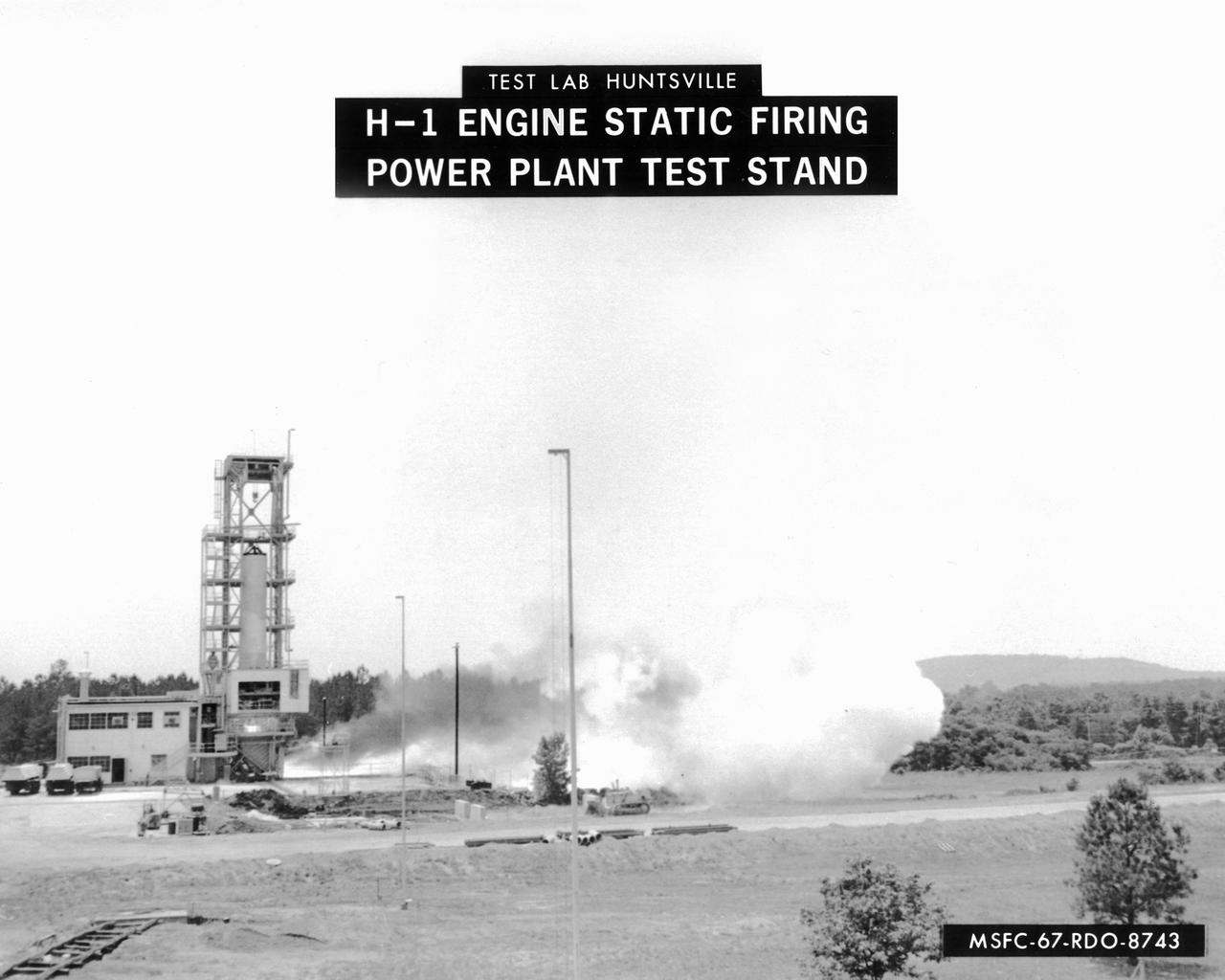
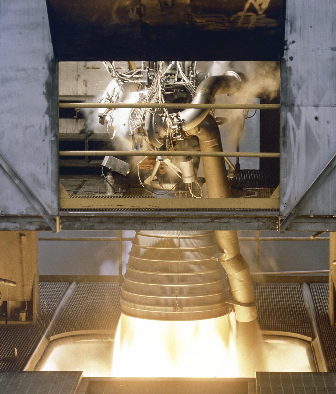
This image depicts a firing of a single H-1 engine at the Marshall Space Flight Center’s (MSFC’s) Power Plant test stand. This 1950s test stand, inherited from the Army, was used to test fire engines until the Test Area was completed in the latter 1960s. The H-1 engine was the workhorse of the first Saturn launch vehicles and used in the Saturn I, Block 1 and II, and in the Saturn IB. The eight H-1 engines were attached to a thrust frame on the vehicle’s aft end in two different ways. Four engines are rigidly attached to the inboard position and canted at a three degree angle to the long axis of the booster. The other four engines, mounted in the outboard position, are canted at six degrees.
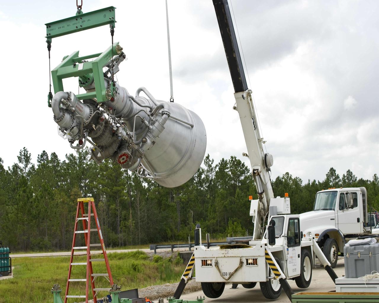
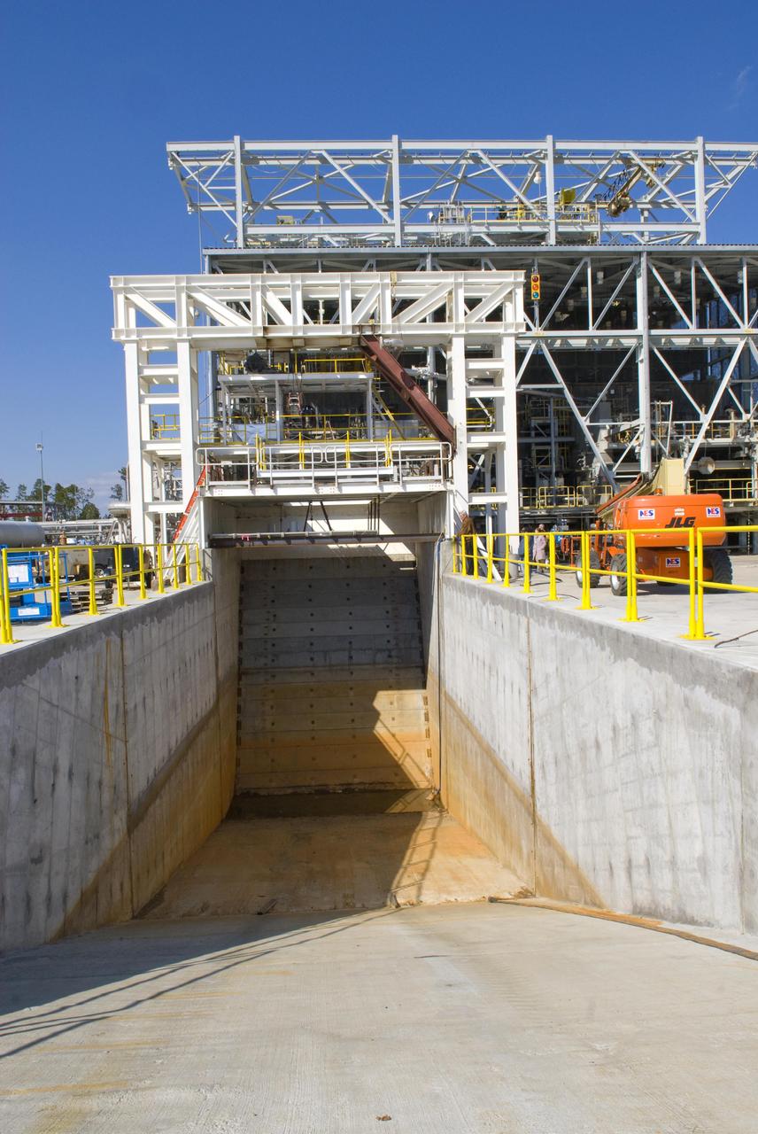
An Aerojet AJ26 rocket engine is hoisted for installation at Stennis Space Center's E-1 Test Stand on July 19. Stennis operators have been preparing the E-1 stand for testing AJ26 engines since April 2009. Modifications included construction of a 27-foot-deep flame deflection trench.

An Aerojet AJ26 rocket engine is hoisted for installation at Stennis Space Center's E-1 Test Stand on July 19. Stennis operators have been preparing the E-1 stand for testing AJ26 engines since April 2009. Modifications included construction of a 27-foot-deep flame deflection trench.
A close-up view of the F-1 Engine for the Saturn V S-IC (first) stage depicts the complexity of the engine. Developed by Rocketdyne under the direction of the Marshall Space Flight Center, the F-1 engine was utilized in a cluster of five engines to propel the Saturn V's first stage, the S-IC. Liquid oxygen and kerosene were used as its propellant. Initially rated at 1,500,000 pounds of thrust, the engine was later uprated to 1,522,000 pounds of thrust after the third Saturn V launch (Apollo 8, the first marned Saturn V mission) in December 1968. The cluster of five F-1 engines burned over 15 tons of propellant per second, during its two and one-half minutes of operation, to take the vehicle to a height of about 36 miles and to a speed of about 6,000 miles per hour.
The test laboratory of the Marshall Space Flight Center (MSFC) tested the F-1 engine, the most powerful rocket engine ever fired at MSFC. The engine was tested on the newly modified Saturn IB Static Test Stand which had been used for three years to test the Saturn I eight-engine booster, S-I (first) stage. In 1961 the test stand was modified to permit static firing of the S-I/S-IB stage and the name of the stand was then changed to the S-IB Static Test Stand. Producing a combined thrust of 7,500,000 pounds, five F-1 engines powered the S-IC (first) stage of the Saturn V vehicle for the marned lunar mission.
The test laboratory of the Marshall Space Flight Center (MSFC) tested the F-1 engine, the most powerful rocket engine ever fired at MSFC. The engine was tested on the newly modified Saturn IB static test stand that had been used for three years to test the Saturn I eight-engine booster, S-I (first) stage. In 1961, the test stand was modified to permit static firing of the S-I/S-IB stage and the name of the stand was then changed to the S-IB Static Test Stand. Producing a combined thrust of 7,500,000 pounds, five F-1 engines powered the S-IC (first) stage of the Saturn V vehicle for the marned lunar mission.
Marshall Space Flight Center (MSFC) was the birthplace of the United States' rocket program. In the early 1960s, most of the rocket development and testing were done at the MSFC. Pictured is an example of what the test engineers would have seen from the pillbox as eight H-1 engines for the first stage of the Saturn I rocket were test fired.
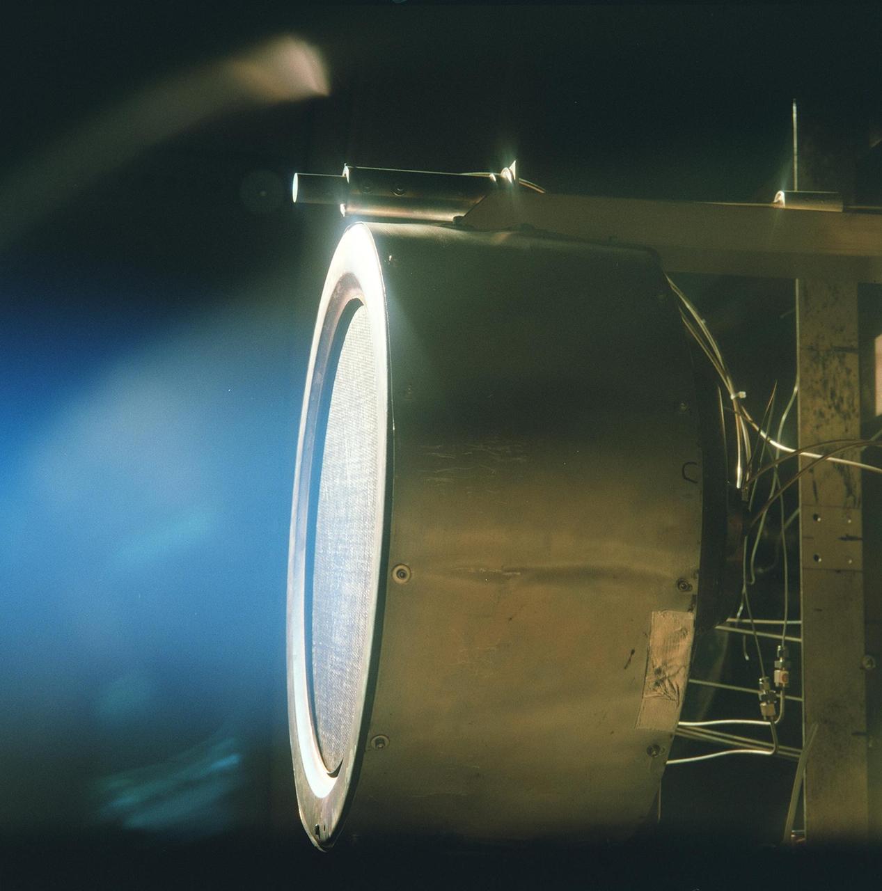
This image of a xenon ion engine prototype, photographed through a port of the vacuum chamber where it was being tested at NASA's Jet Propulsion Laboratory, shows the faint blue glow of charged atoms being emitted from the engine. The engine is now in an ongoing extended- life test, in a vacuum test chamber at JPL, and has run for almost 500 days (12,000 hours) and is scheduled to complete nearly 625 days (15,000 hours) by the end of 2001. A similar engine powers the New Millennium Program's flagship mission, Deep Space 1, which uses the ion engine in a trip through the solar system. The engine, weighing 17.6 pounds (8 kilograms), is 15.7 inches (40 centimeters) in diameter and 15.7 inches long. The actual thrust comes from accelerating and expelling positively charged xenon atoms, or ions. While the ions are fired in great numbers out the thruster at more than 110,000 kilometers (68,000 miles) per hour, their mass is so low that the engine produces a gentle thrust of only 90 millinewtons (20-thousandths of a pound). http://photojournal.jpl.nasa.gov/catalog/PIA04238
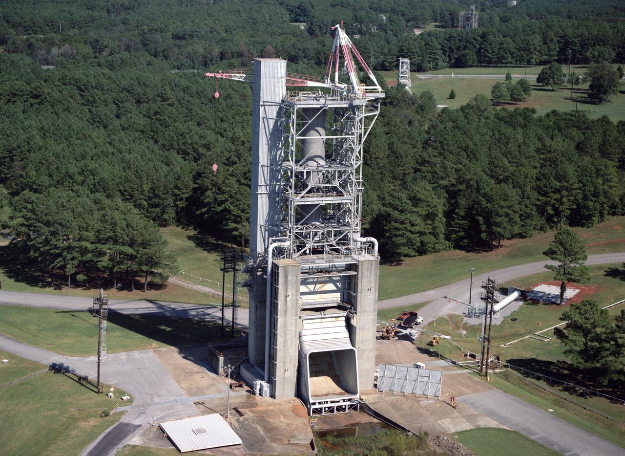
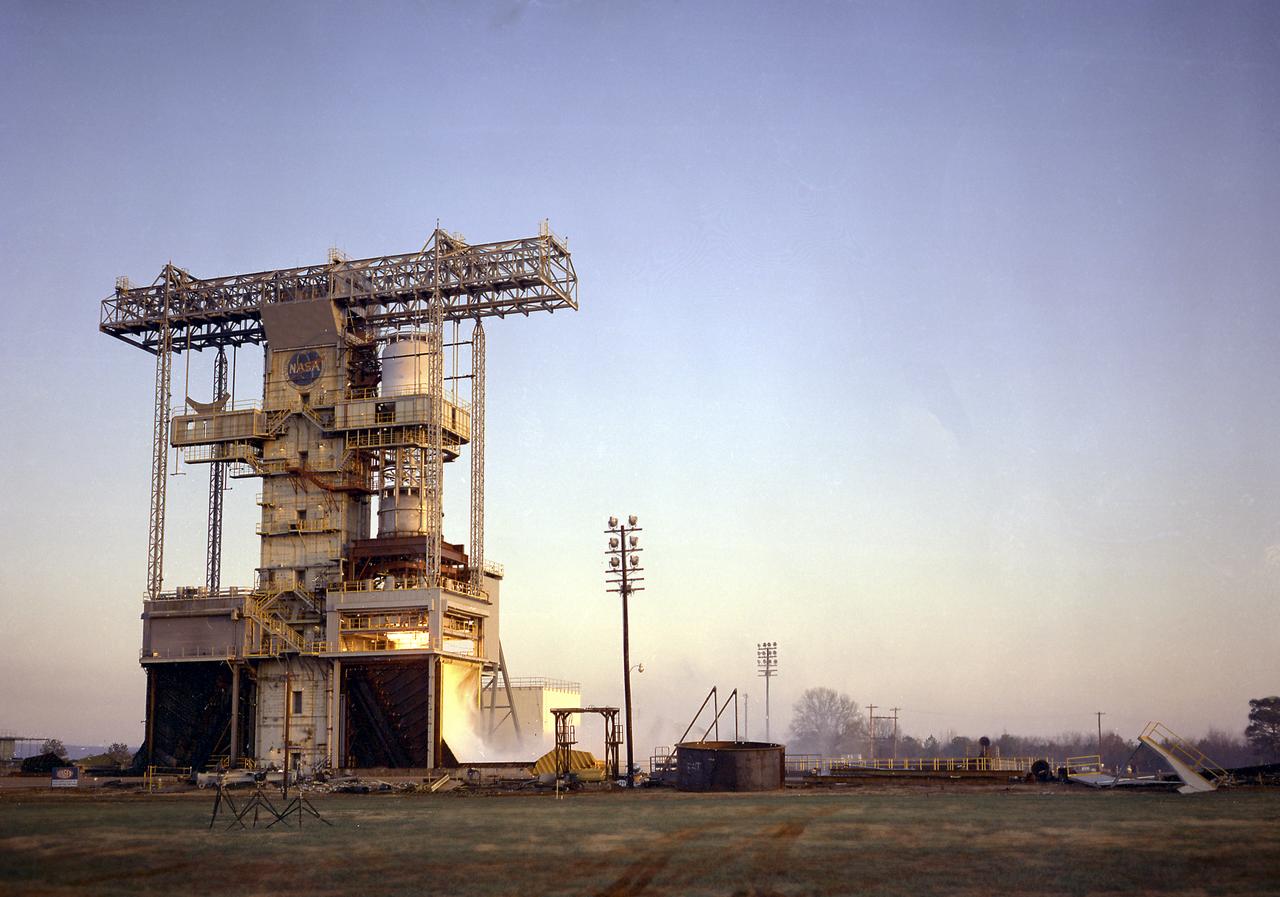
Marshall Space Flight Center's F-1 Engine Test Stand is shown in this picture. Constructed in 1963, the test stand is a vertical engine firing test stand, 239 feet in elevation and 4,600 square feet in area at the base, and was designed to assist in the development of the F-1 Engine. Capability is provided for static firing of 1.5 million pounds of thrust using liquid oxygen and kerosene. The foundation of the stand is keyed into the bedrock approximately 40 feet below grade.
The June 8, 2012, test of the J-2X powerpack on the A-1 Test Stand at NASA's Stennis Space Center set a new record of test duration, lasting 1,150 seconds, almost 20 full minutes. It was the longest-duration test firing ever conducted in the A Test Complex. The results of this test will be useful for determining performance and hardware life for the J-2X engine turbopumps.
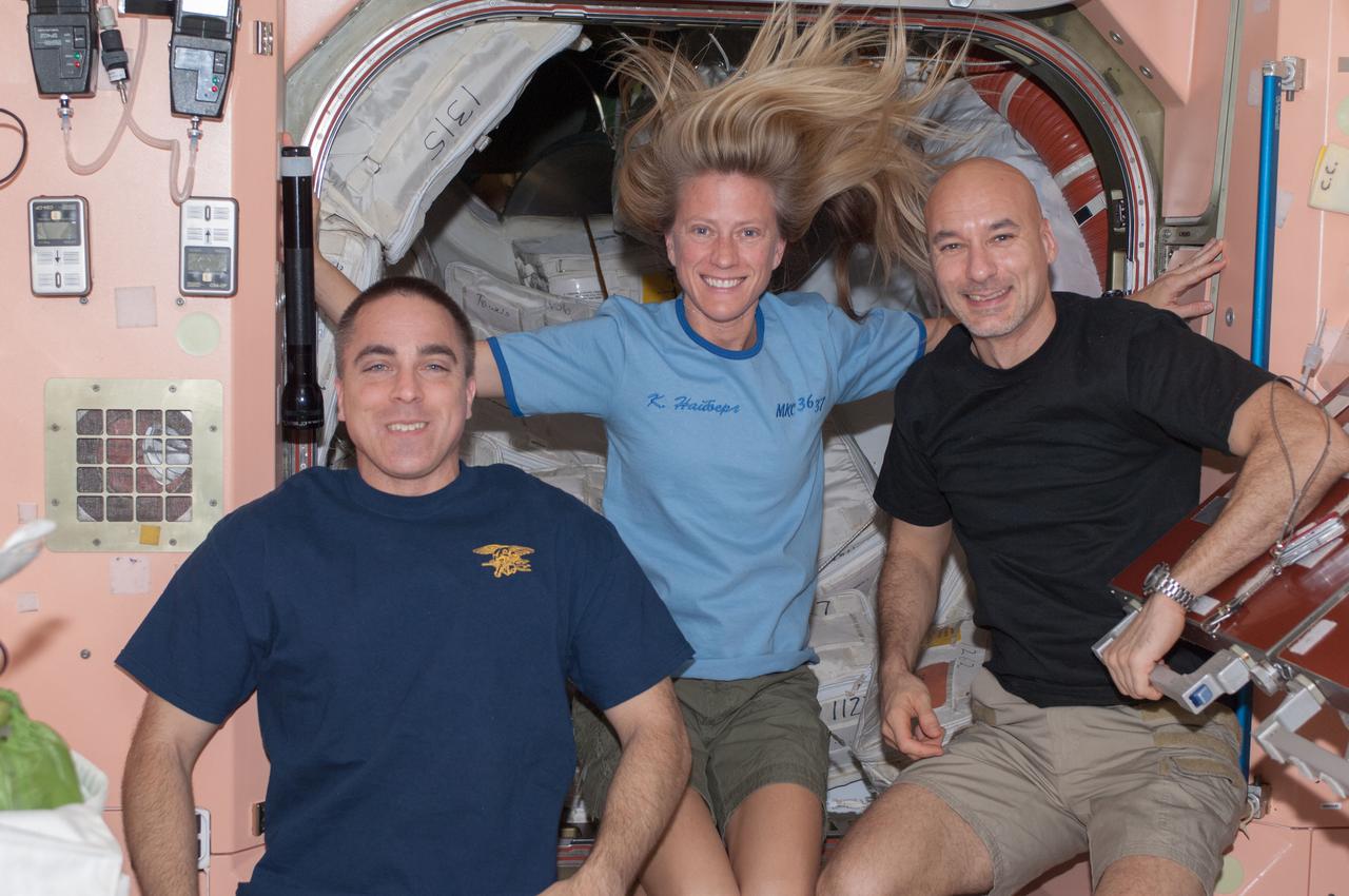
View of Astronauts Chris Cassidy (left),Karen Nyberg (center) and European Space Agency astronaut Luca Parmitano,all Expedition 36 flight engineers,in the Node 1 module.
Core components of the J-2X engine being designed for NASA's Constellation Program recently were installed on the A-1 Test Stand at NASA's Stennis Space Center near Bay St. Louis, Miss. Tests of the components, known as Powerpack 1A, will be conducted from November 2007 through February 2008. The Powerpack 1A test article consists of a gas generator and engine turbopumps originally developed for the Apollo Program that put Americans on the moon in the late 1960s and early 1970s. Engineers are testing these heritage components to obtain data that will help them modify the turbomachinery to meet the higher performance requirements of the Ares I and Ares V launch vehicles. The upcoming tests will simulate inlet and outlet conditions that would be present on the turbomachinery during a full-up engine hot-fire test.
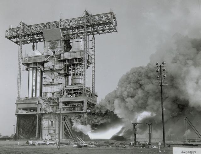
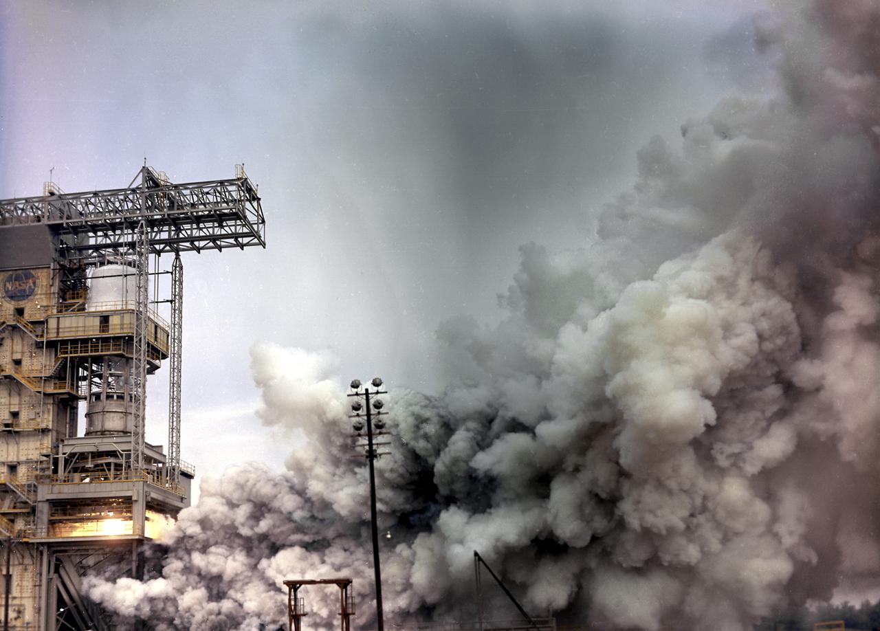
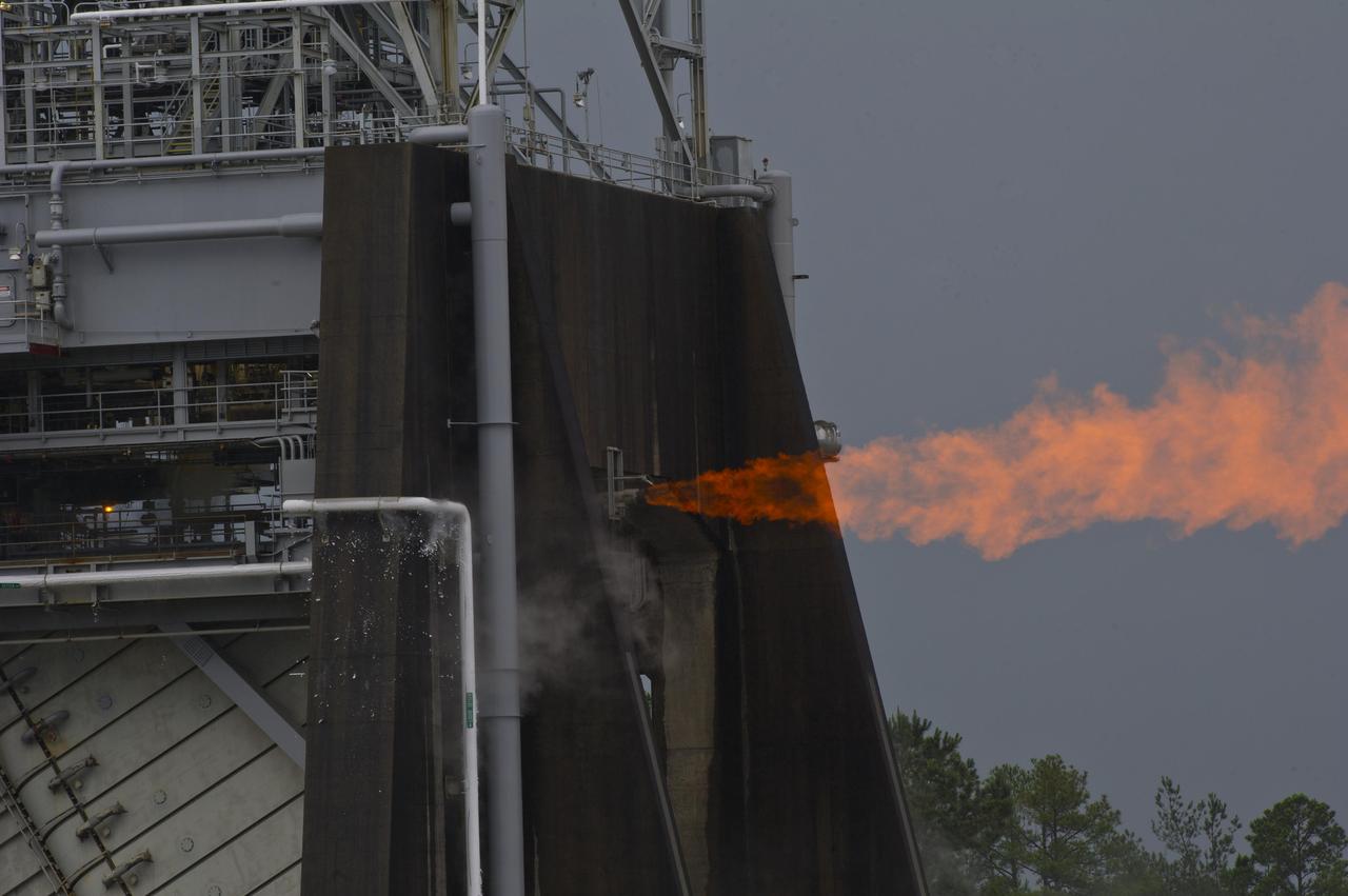
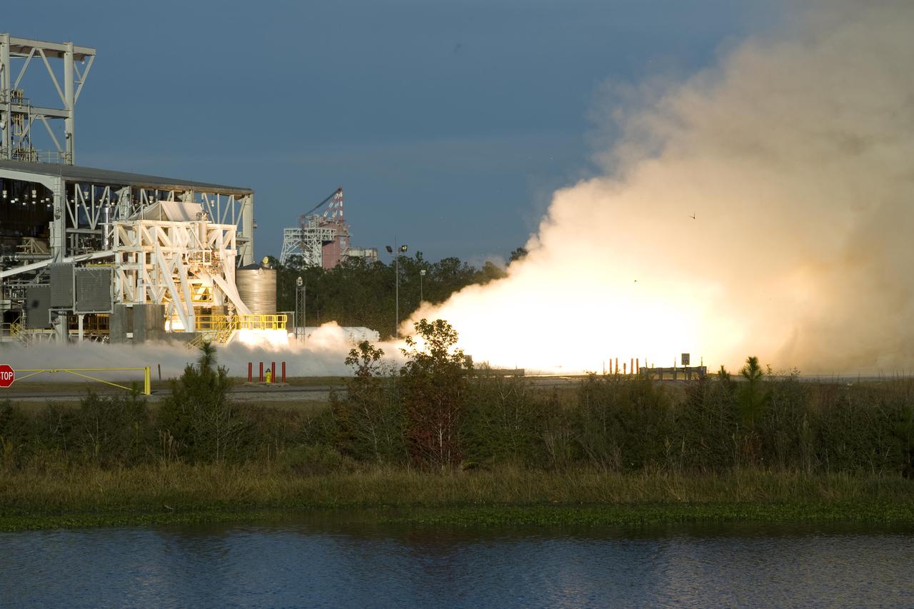
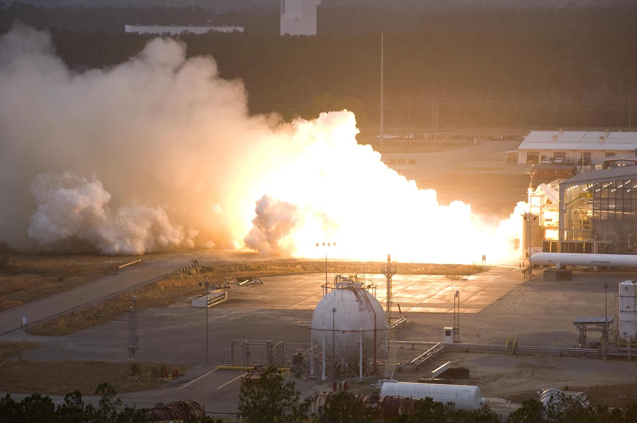
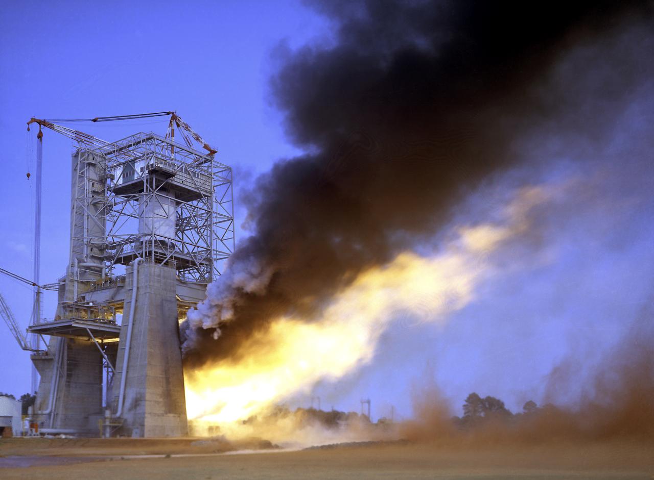
The flame and exhaust from the test firing of an F-1 engine blast out from the Saturn S-IB Static Test Stand in the east test area of the Marshall Space Flight Center. A Cluster of five F-1 engines, located in the S-IC (first) stage of the Saturn V vehicle, provided over 7,500,000 pounds of thrust to launch the giant rocket. The towering 363-foot Saturn V was a multistage, multiengine launch vehicle standing taller than the Statue of Liberty. Altogether, the Saturn V engines produced as much power as 85 Hoover Dams.
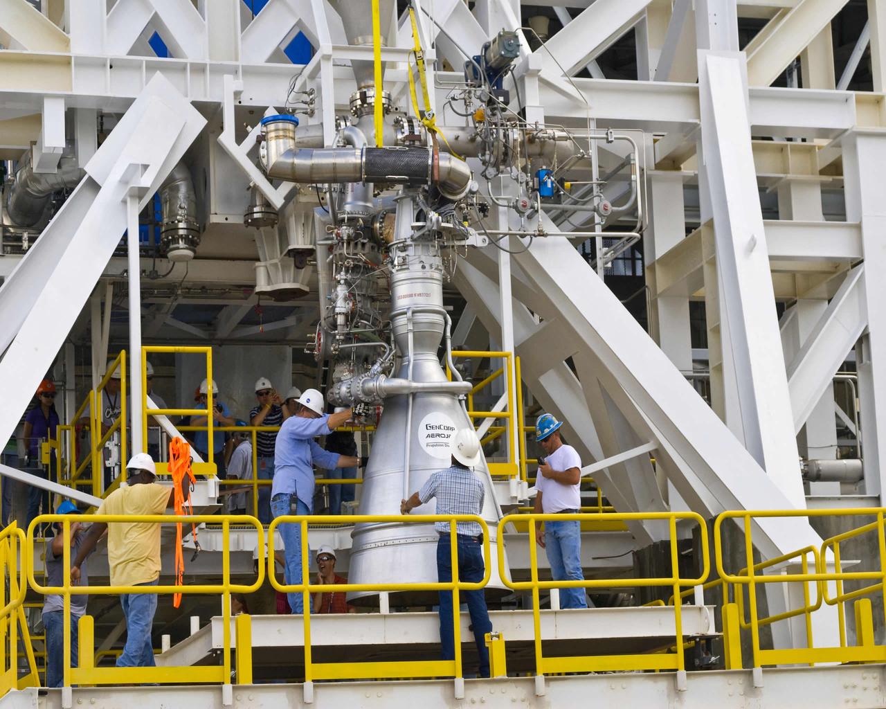
Stennis employees at the E-1 Test Stand position an Aerojet AJ26 rocket engine in preparation for a series of early tests. Stennis has partnered with Orbital Sciences Corporation to test the rocket engine for the company's commercial cargo flights to the International Space Station.
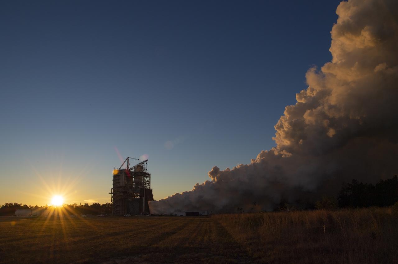
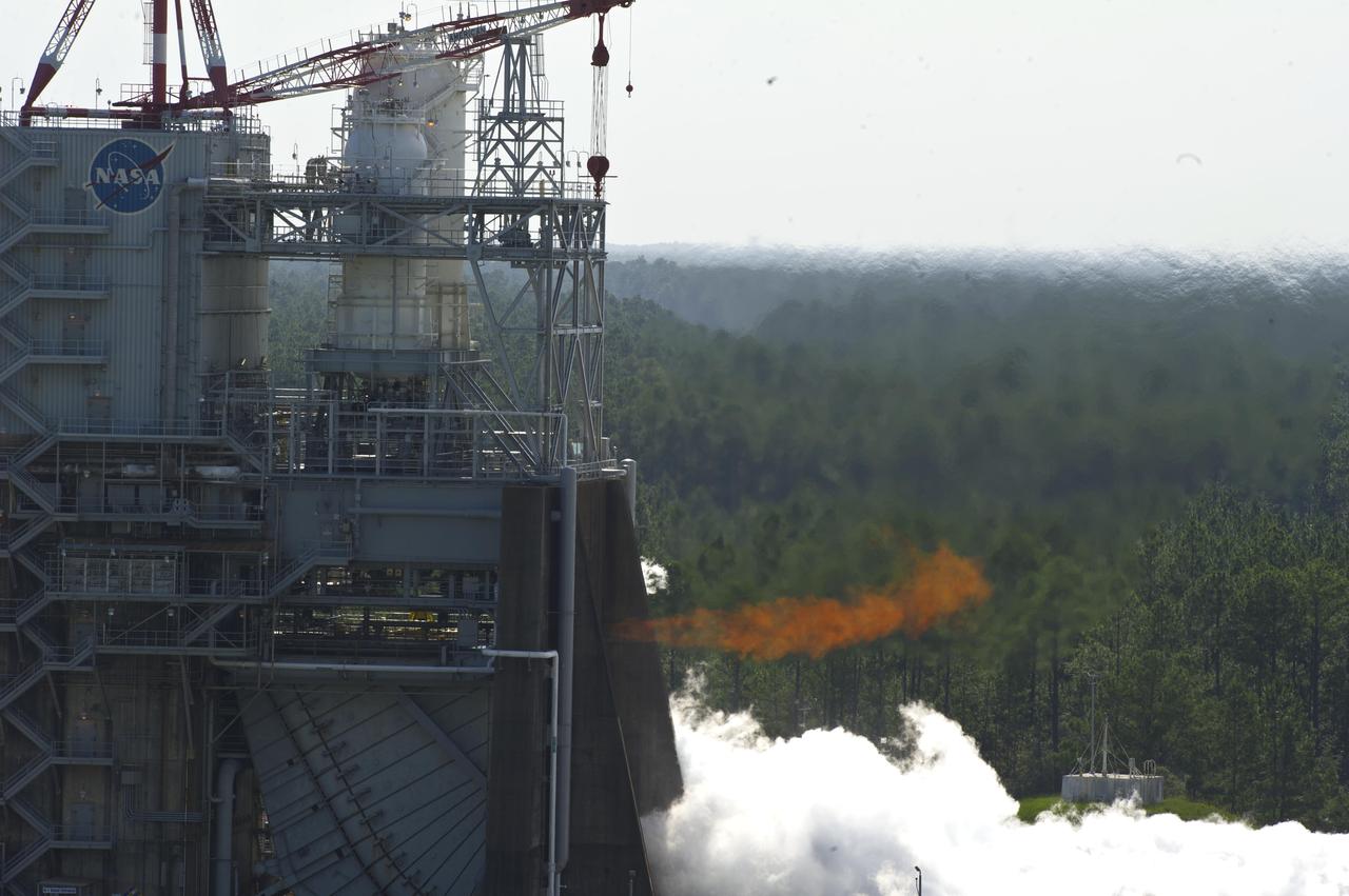
An RS-25 engine is fired at sunset on Nov. 15 on the A-1 test stand at Stennis Space Center. The 650-second duration test represents the time three such engines would need to fire to burn up propellant and power the rocket into orbit, even if the fourth shut down early during an SLS launch.
Engineers and technicians at the Marshall Space Flight Center were installing an F-I engine on the Saturn V S-IC (first) stage thrust structure in building 4705. The S-IC (first) stage used five F-1 engines that produced a total thrust of 7,500,000 pounds as each engine produced 1,500,000 pounds of thrust. The S-IC stage lifted the Saturn V vehicle and Apollo spacecraft from the launch pad.
Fire and steam signal a successful test firing of Orbital Sciences Corporation's Aerojet AJ26 rocket engine at John C. Stennis Space Center. AJ26 engines will be used to power Orbital's Taurus II space vehicle on commercial cargo flights to the International Space Station. On Nov. 10, operators at Stennis' E-1 Test Stand conducted a 10-second test fire of the engine, the first of a series of three verification tests. Orbital has partnered with NASA to provide eight missions to the ISS by 2015.
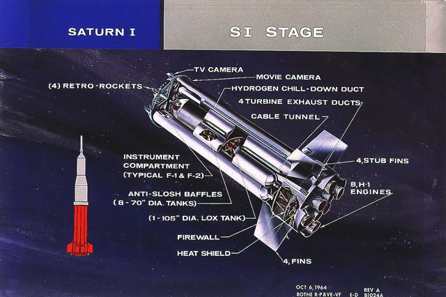
This cutaway illustrates the S-I stage, the first stage of the Saturn I vehicle developed by the Marshall Space Flight Center (MSFC). The stage was propelled by a cluster of eight H-1 engines, capable of producing 1,500,000 pounds of thrust.
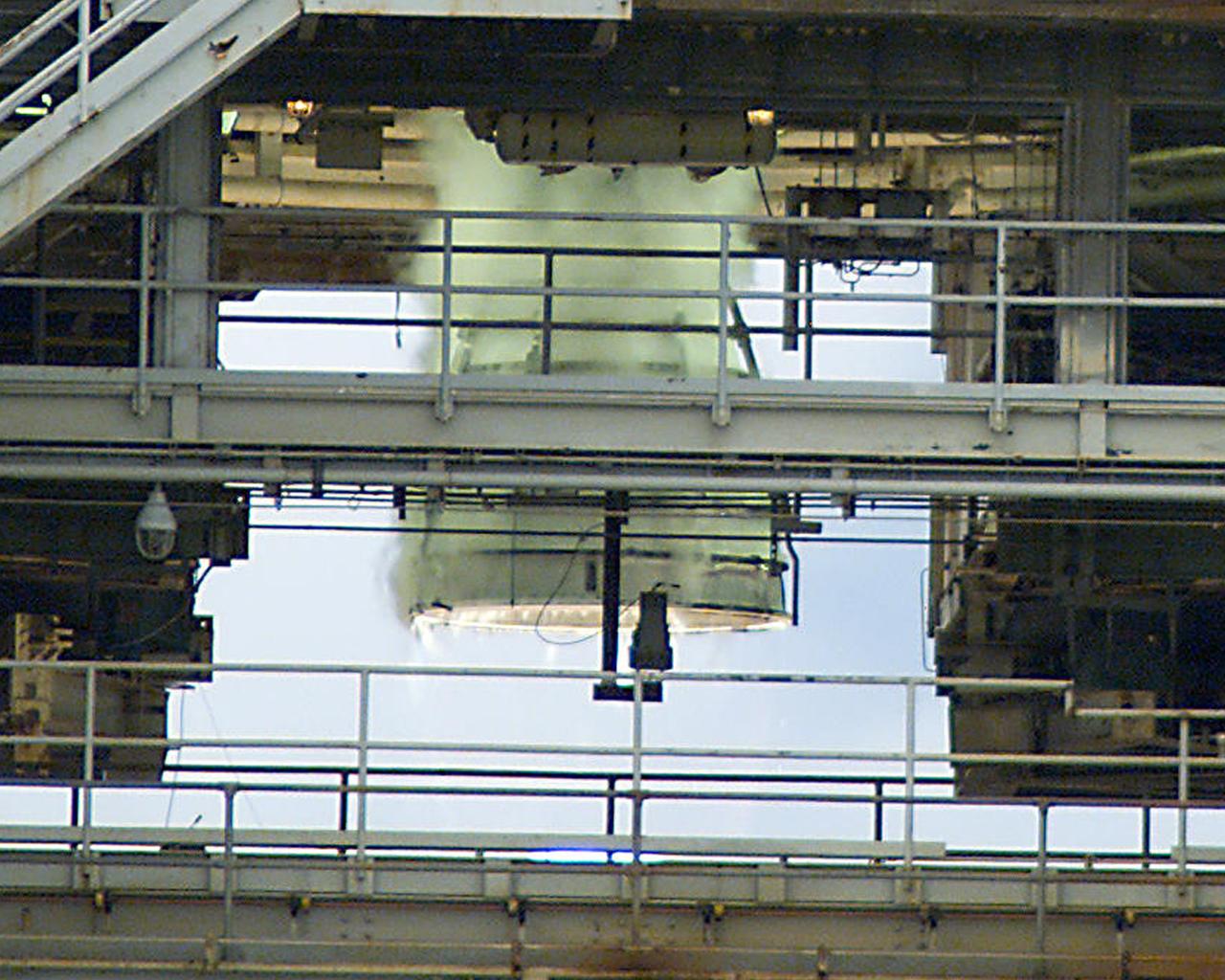
This close-up photo was taken during testing of a Space Shuttle Main Engine on the A-1 Test Stand at Stennis Space Center near Bay St. Louis, Miss. The test was conducted June 19, 2003.
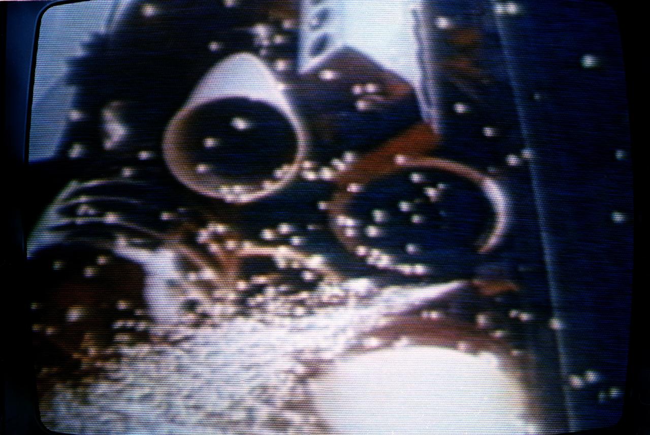
S84-36146 (12 April 1981) --- This close-up television view captures the flames of the space shuttle Columbia’s three main engines just seconds before launch and the beginning of the STS-1 mission. Photo credit: NASA or National Aeronautics and Space Administration
Crews at NASA’s Stennis Space Center remove an RS-25 rocket engine from the A-1 test stand on Nov. 1, 2021, following a series of successful tests.

Operators at NASA's John C. Stennis Space Center are completing modifications to the E-1 Test Stand to begin testing Aerojet AJ26 rocket engines in early summer of 2010. Modifications include construction of a 27-foot-deep flame deflector trench. The AJ26 rocket engines will be used to power Orbital Sciences Corp.'s Taurus II space vehicles to provide commercial cargo transportation missions to the International Space Station for NASA. Stennis has partnered with Orbital to test all engines for the transport missions.
Operators at NASA's John C. Stennis Space Center are completing modifications to the E-1 Test Stand to begin testing Aerojet AJ26 rocket engines in early summer of 2010. Modifications include construction of a 27-foot-deep flame deflector trench. The AJ26 rocket engines will be used to power Orbital Sciences Corp.'s Taurus II space vehicles to provide commercial cargo transportation missions to the International Space Station for NASA. Stennis has partnered with Orbital to test all engines for the transport missions.
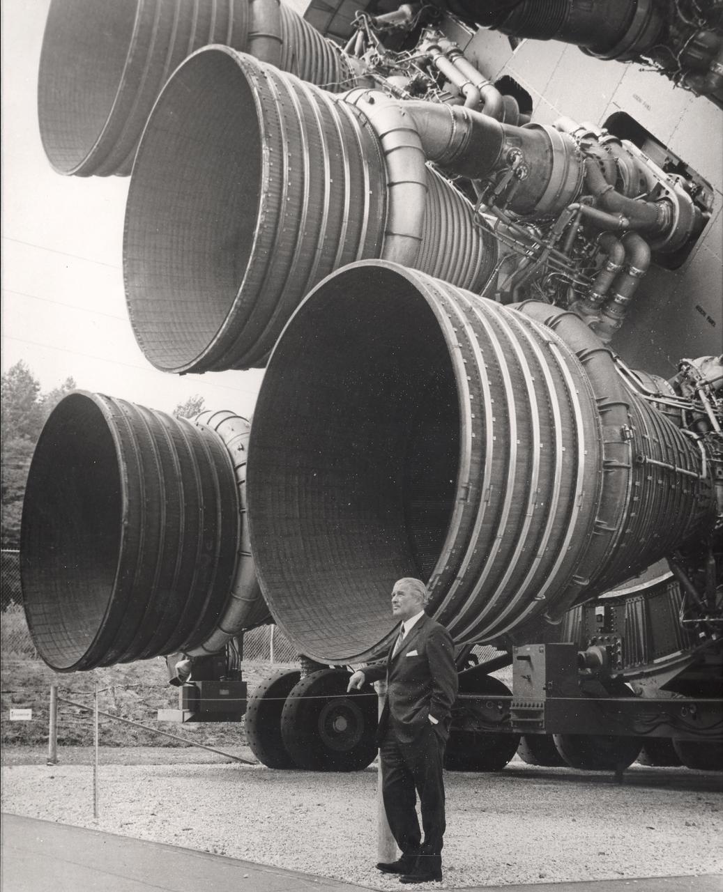
A pioneer of America's space program, Dr. von Braun stands by the five F-1 engines of the Saturn V launch vehicle. This Saturn V vehicle is an actual test vehicle which has been displayed at the U.S. Space Rocket Center in Huntsville, Alabama. Designed and developed by Rocketdyne under the direction of the Marshall Space Flight Center, a cluster of five F-1 engines was mounted on the Saturn V S-IC (first) stage. The engines measured 19-feet tall by 12.5-feet at the nozzle exit and burned 15 tons of liquid oxygen and kerosene each second to produce 7,500,000 pounds of thrust. The S-IC stage is the first stage, or booster, of a 364-foot long rocket that ultimately took astronauts to the Moon.
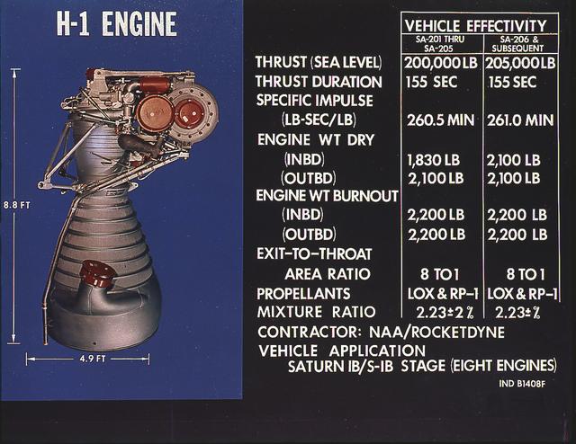
H-1 engine characteristics: The H-1 engine was developed under the management of the Marshall Space Flight Center (MSFC). The cluster of eight H-1 engines was used to power the first stage of the Saturn I (S-I stage) and Saturn IB (S-IVB stage) launch vehicles, and produced 188,00 pounds of thrust, a combined thrust of 1,500,000 pounds, later uprated to 205,000 pounds of thrust and a combined total thrust of 1,650,000 pounds for the Saturn IB program.
John C. Stennis Space Center engineers conduct a 55-second test fire of Aerojet's liquid-fuel AJ26 rocket engine that will power the first stage of Orbital Sciences Corporation's Taurus II space launch vehicle. The Dec. 17, 2010 test was conducted on the E-1 Test Stand at Stennis in support of NASA's Commercial Transportation Services partnerships to enable commercial cargo flights to the International Space Station. Orbital is under contract with NASA to provide eight cargo missions to the space station through 2015.

John C. Stennis Space Center engineers conduct a 55-second test fire of Aerojet's liquid-fuel AJ26 rocket engine that will power the first stage of Orbital Sciences Corporation's Taurus II space launch vehicle. The Dec. 17, 2010 test was conducted on the E-1 Test Stand at Stennis in support of NASA's Commercial Transportation Services partnerships to enable commercial cargo flights to the International Space Station. Orbital is under contract with NASA to provide eight cargo missions to the space station through 2015.
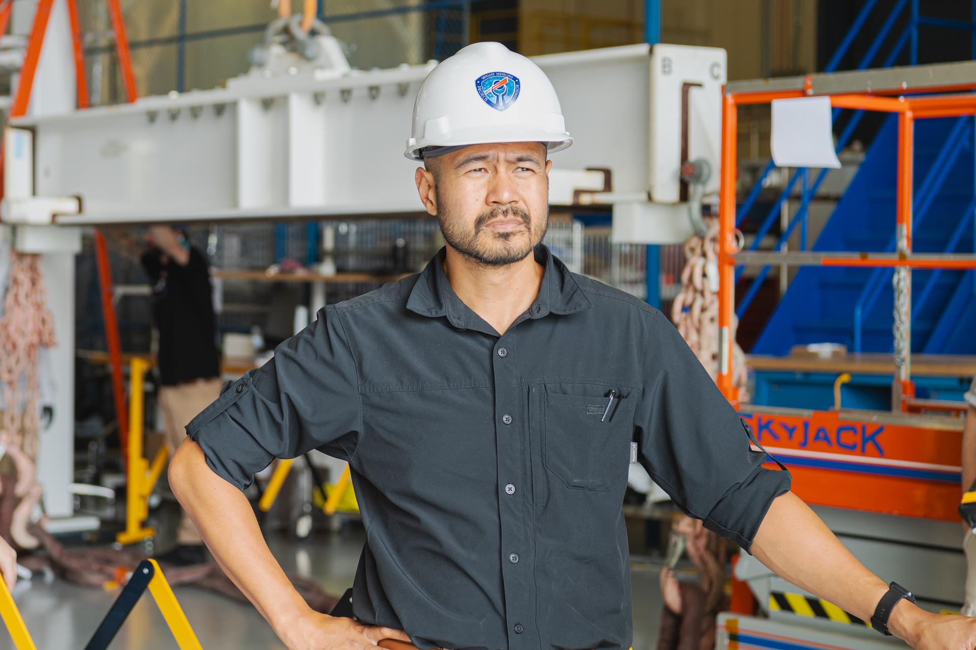
Mechanical Integration and Testing Engineer, Jeff Geroso, watches as the OSAM-1 spacecraft arrives at Goddard Space Flight Center, Greenbelt, Md., Sept 20, 2023. Geroso is responsible for the receiving operations involving the OSAM-1 spacecraft bus. This photo has been reviewed by OSAM1 project management and the Export Control Office and is released for public view. NASA/ Mike Guinto
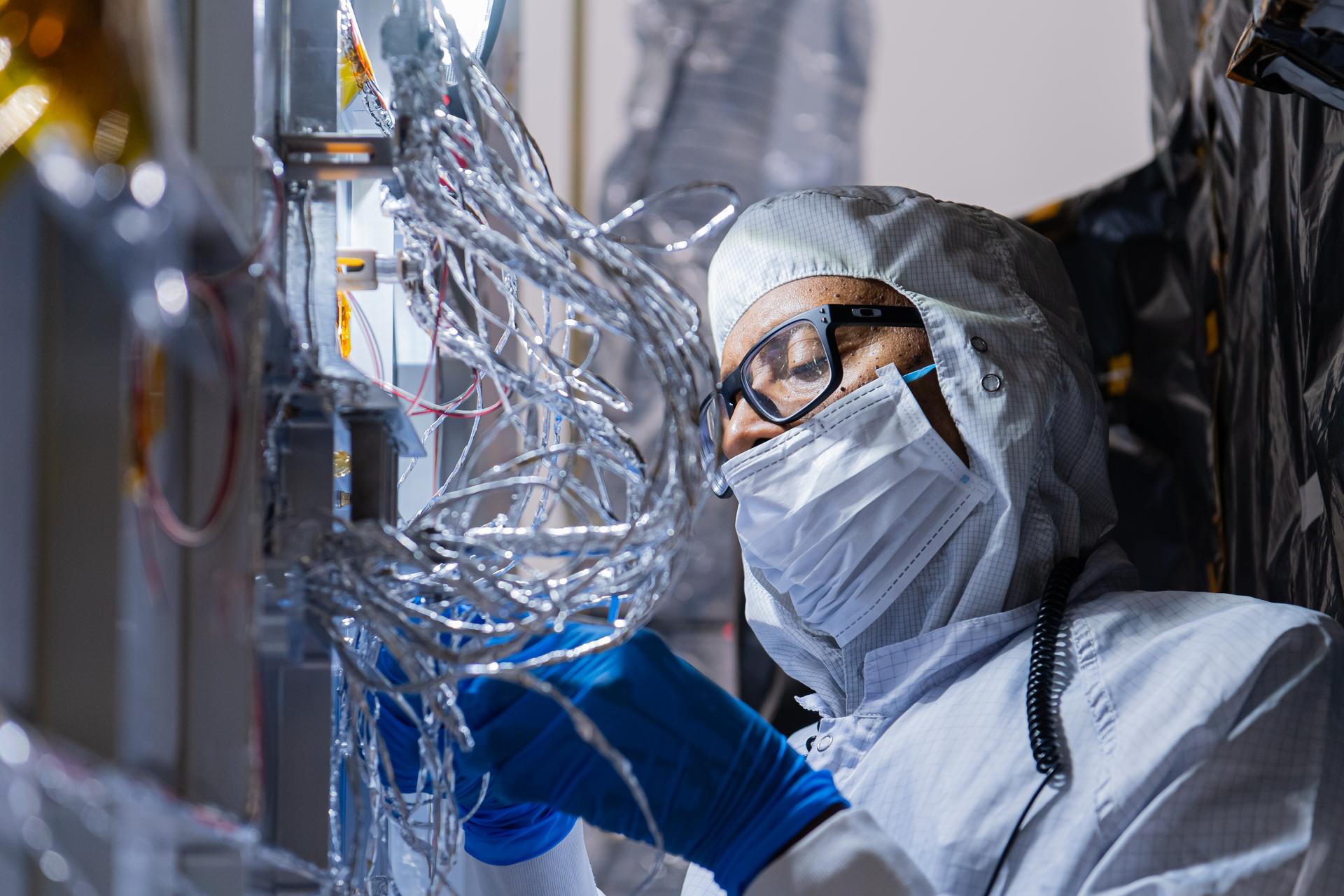
OSAM-1 Electrical Engineer Gregory Griffin tapes hardware on the underside of the OSAM-1 Servicing Payload inside cleanroom at Goddard Space Flight Center, Greenbelt Md., Aug 19, 2024. This photo has been reviewed by the Export Control Office, project Management, and Maxar release authority and is released for public view. NASA/Mike Guinto
Engineers at the Marshall Space Flight Center install the F-1 engines on the S-IC stage thrust structure at the S-IC static test stand. Engines are installed on the stage after it has been placed in the test stand. Five F-1 engines, each weighing 10 tons, gave the booster a total thrust of 7,500,000 pounds, roughly equivalent to 160 million horsepower.
Engineers at the Marshall Space Flight Center install the F-1 engines on the S-IC stage thrust structure at the S-IC static test stand. Engines are installed on the stage after it has been placed in the test stand. Five F-1 engines, each weighing 10 tons, gave the booster a total thrust of 7,500,000 pounds, roughly equivalent to 160 million horsepower.
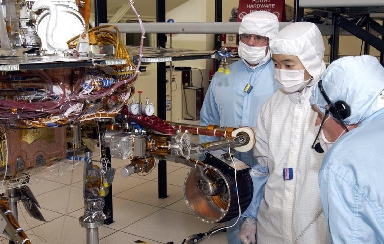
JPL engineers examine the robotic arm of NASA Mars Exploration Rover 1.
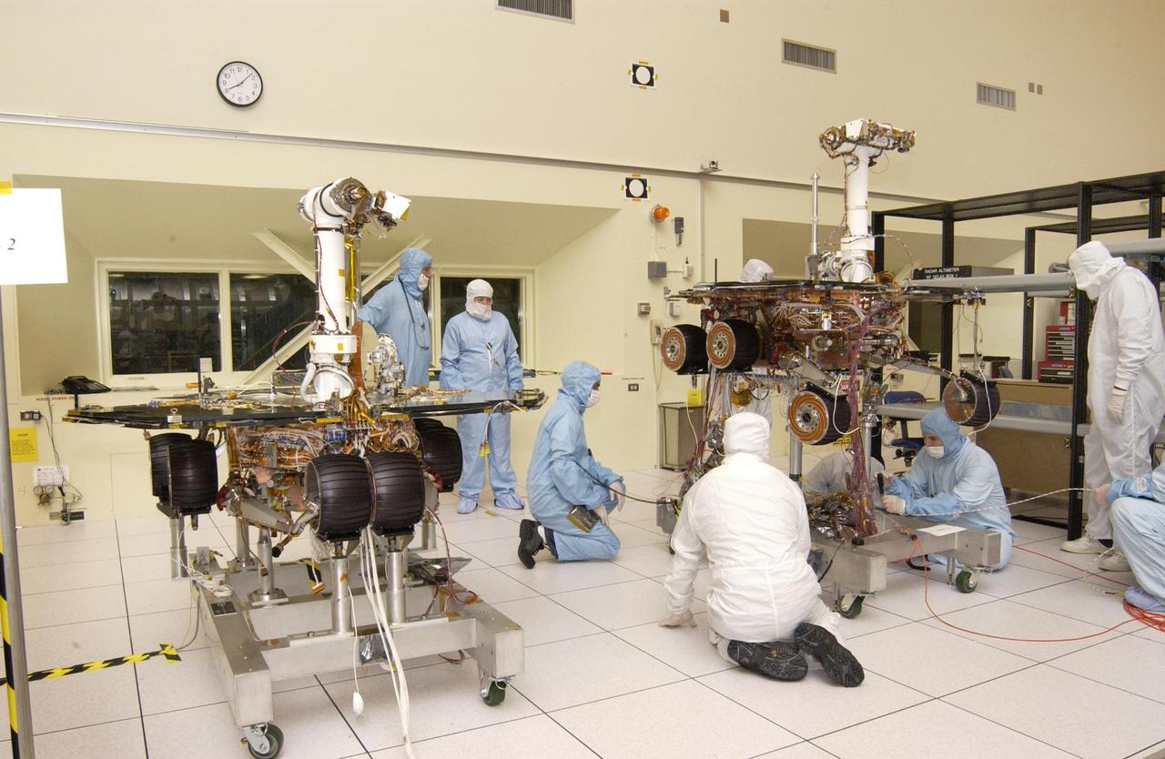
JPL engineers making adjustments to NASA Mars Exploration Rover 1.
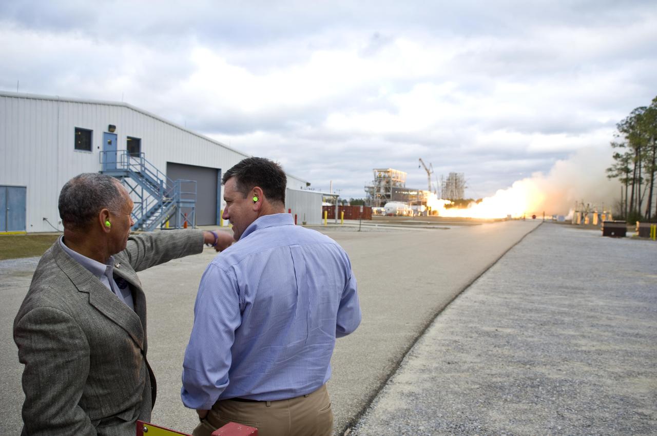
NASA Administrator Charles Bolden (l) and John C. Stennis Space Center Director Patrick Scheuermann watch the successful test of the first Aerojet AJ26 flight engine Feb. 7, 2011. The test was conducted on the E-1 Test Stand at Stennis. The engine now will be sent to Wallops Flight Facility in Virginia, where it will be used to power the first stage of Orbital Sciences Corporation's Taurus II space vehicle. The Feb. 7 test supports NASA's commitment to partner with companies to provide commercial cargo flights to the International Space Station. NASA has partnered with Orbital to carry out the first of eight cargo missions to the space station in early 2012.
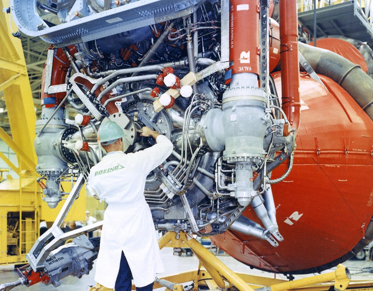
This image depicts a Boeing worker installing an F-1 engine on the Saturn V S-IC flight stage at the Michoud Assembly Facility (MAF). The Saturn IB and Saturn V first stages were manufactured at the MAF, located 24 kilometers (approximately 15 miles) east of downtown New Orleans, Louisiana. The prime contractors, Chrysler and Boeing, jointly occupied the MAF. The basic manufacturing building boasted 43 acres under one roof. By 1964, NASA added a separate engineering and office building, vertical assembly building, and test stage building.
The Stennis Space Center conducted the final space shuttle main engine test on its A-1 Test Stand Friday. The A-1 Test Stand was the site of the first test on a shuttle main engine in 1975. Stennis will continue testing shuttle main engines on its A-2 Test Stand through the end of the Space Shuttle Program in 2010. The A-1 stand begins a new chapter in its operational history in October. It will be temporarily decommissioned to convert it for testing the J-2X engine, which will power the upper stage of NASA's new crew launch vehicle, the Ares I. Although this ends the stand's work on the Space Shuttle Program, it will soon be used for the rocket that will carry America's next generation human spacecraft, Orion.
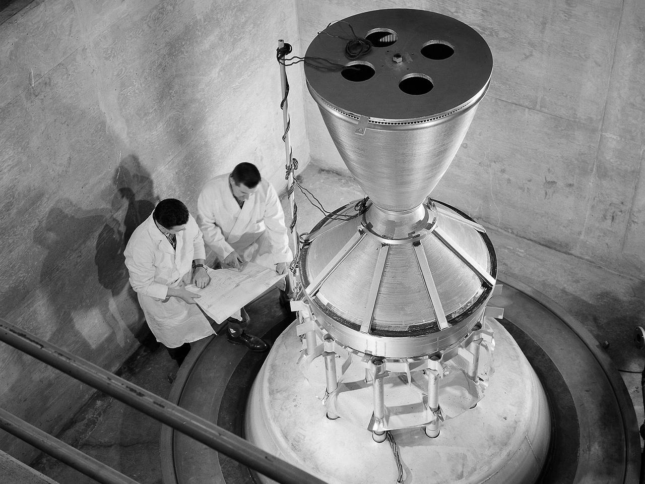
Technicians manufacture a nozzle for the Kiwi B-1-B nuclear rocket engine in the Fabrication Shop’s vacuum oven at the National Aeronautics and Space Administration (NASA) Lewis Research Center. The Nuclear Engine for Rocket Vehicle Applications (NERVA) was a joint NASA and Atomic Energy Commission (AEC) endeavor to develop a nuclear-powered rocket for both long-range missions to Mars and as a possible upper-stage for the Apollo Program. The early portion of the program consisted of basic reactor and fuel system research. This was followed by a series of Kiwi reactors built to test basic nuclear rocket principles in a non-flying nuclear engine. The next phase, NERVA, would create an entire flyable engine. The final phase of the program, called Reactor-In-Flight-Test, would be an actual launch test. The AEC was responsible for designing the nuclear reactor and overall engine. NASA Lewis was responsible for developing the liquid-hydrogen fuel system. The turbopump, which pumped the fuels from the storage tanks to the engine, was the primary tool for restarting the engine. The NERVA had to be able to restart in space on its own using a safe preprogrammed startup system. Lewis researchers endeavored to design and test this system. This non-nuclear Kiwi engine, seen here, was being prepared for tests at Lewis’ High Energy Rocket Engine Research Facility (B-1) located at Plum Brook Station. The tests were designed to start an unfueled Kiwi B-1-B reactor and its Aerojet Mark IX turbopump without any external power.
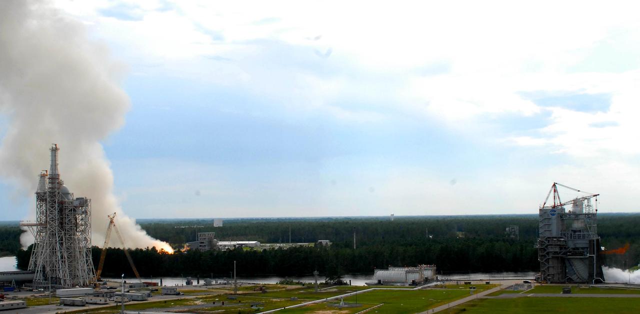
Two large-engine tests were conducted simultaneously for the first time at Stennis Space Center on Aug. 16. A plume on the left indicates a test on the facility's E-1 Test Stand. On the right, a finger of fire indicates a test under way on the A-1 Test Stand. In another first, both tests were conducted by female engineers. The image was taken from atop the facility's A-2 Test Stand, offering a panoramic view that includes the new A-3 Test Stand under construction to the left.
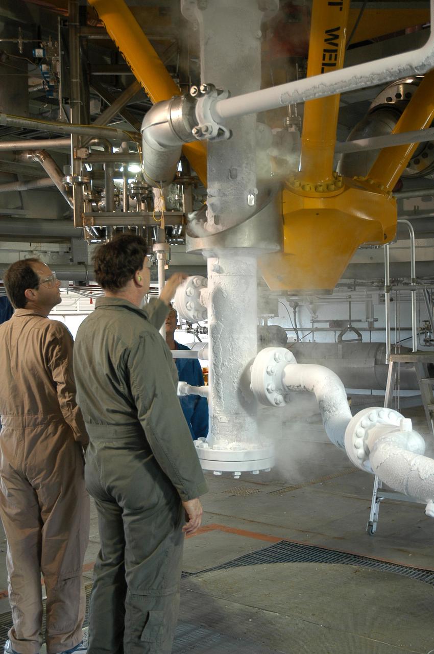
Team members check the progress of a liquid nitrogen cold shock test on the A-1 Test Stand at Stennis Space Center on Sept. 15. The cold shock test is used to confirm the test stand's support system can withstand test conditions, when super-cold rocket engine propellant is piped. The A-1 Test Stand is preparing to conduct tests on the powerpack component of the J-2X rocket engine, beginning in early 2012.

Two large-engine tests were conducted simultaneously for the first time at Stennis Space Center on Aug. 16. A plume on the left indicates a test on the facility's E-1 Test Stand. On the right, a finger of fire indicates a test under way on the A-1 Test Stand. In another first, both tests were conducted by female engineers. The image was taken from atop the facility's A-2 Test Stand, offering a panoramic view that includes the new A-3 Test Stand under construction to the left.
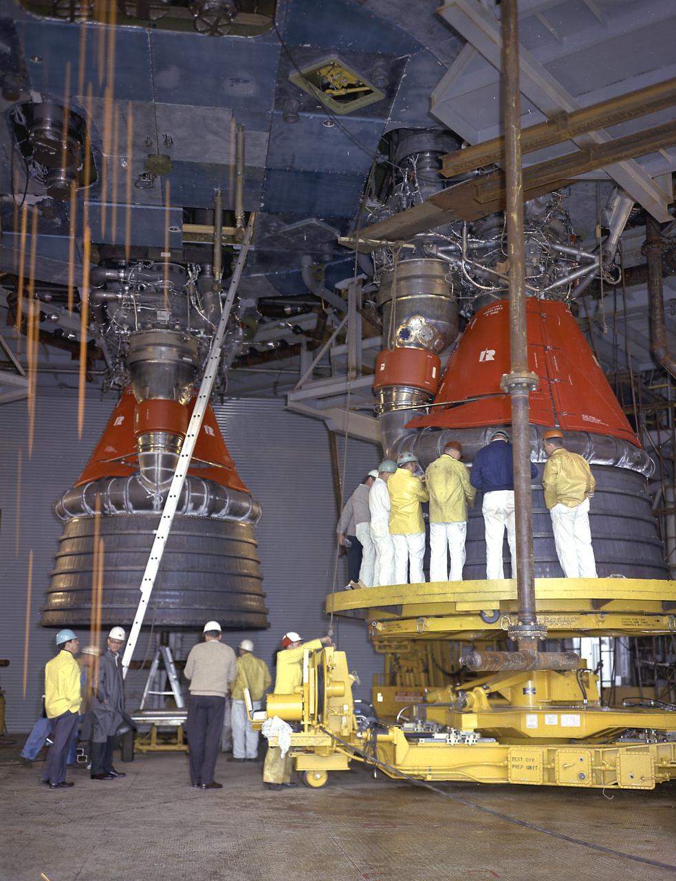
Workers at the Michoud Assembly Facility near New Orleans, Louisiana install the H-1 engines into the S-IB stage, the Saturn IB launch vehicle's first stage. Developed by the Marshall Space Flight Center and built by the Chrysler Corporation at MAF, the 90,000-pound booster utilized eight H-1 engines to produce a combined thrust of 1,600,000 pounds.
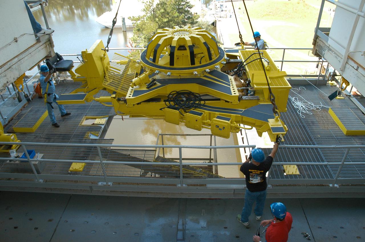
Employees maneuver a vertical engine installer into place on the A-1 Test Stand at Stennis Space Center on Sept. 23. Installation of the equipment was a milestone event as the historic stand underwent modifications for testing the powerpack component of NASA's new J-2X rocket engine in development.
Workers at the Michoud Assembly Facility (MAF) near New Orleans, Louisiana, install the last engine on the S-IB stage. Developed by the Marshall Space Flight Center (MSFC) and built by the Chrysler Corporation at MAF, the S-IB stage utilized eight H-1 engines to produce a combined thrust of 1,600,000 pounds.
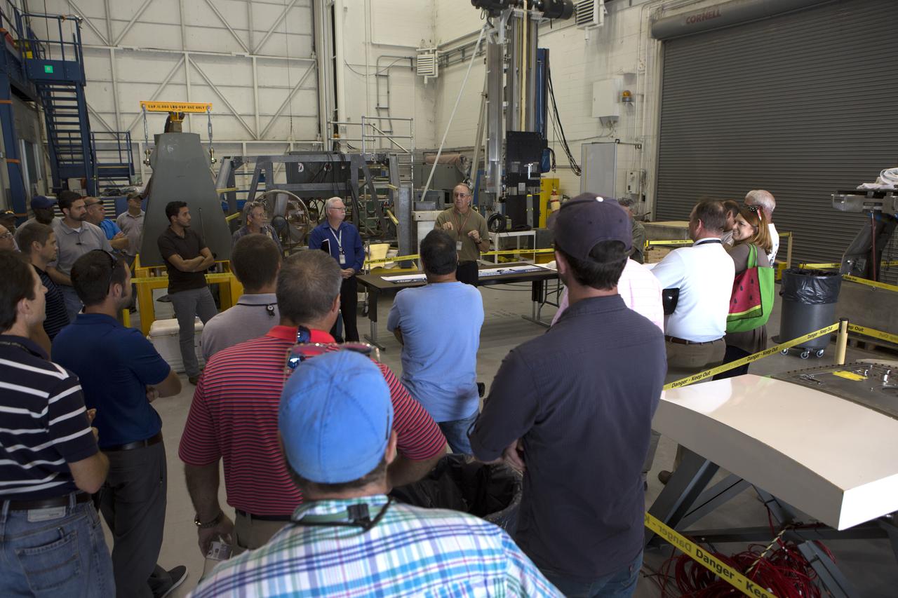
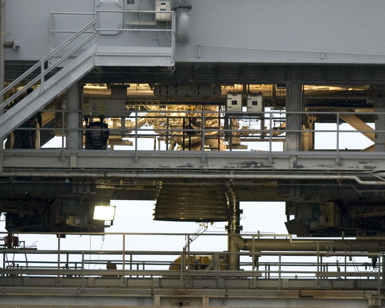
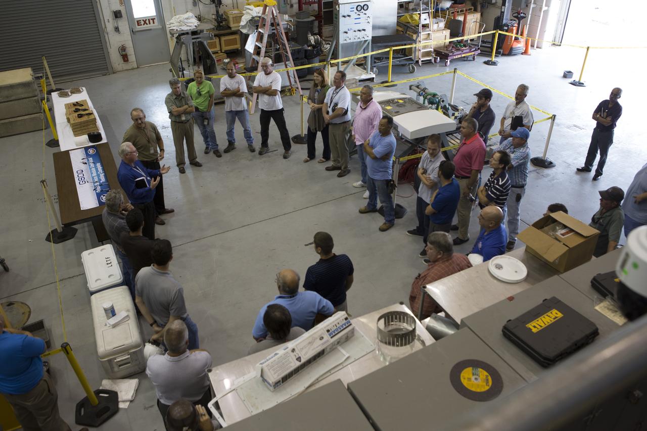
Testing of the Orion Service Module Umbilical (OSMU) was completed at the Launch Equipment Test Facility at NASA’s Kennedy Space Center in Florida. The OSMU was attached to Vehicle Motion Simulator 1 for a series of simulated launch tests to validate it for installation on the mobile launcher. Patrick Simpkins, director of Engineering, speaks to the test team during an event to mark the end of testing. The mobile launcher tower will be equipped with a number of lines, called umbilicals that will connect to the Space Launch System rocket and Orion spacecraft for Exploration Mission-1 (EM-1). The OSMU will be located high on the mobile launcher tower and, prior to launch, will transfer liquid coolant for the electronics and air for the Environmental Control System to the Orion service module that houses these critical systems to support the spacecraft. Kennedy's Engineering Directorate is providing support to the Ground Systems Development and Operations Program for testing of the OSMU. EM-1 is scheduled to launch in 2018.
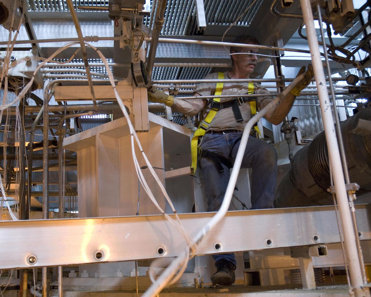
Phil Schemanski of Pratt & Whitney Rocketdyne removes equipment inside the thrust drum on the A-1 Test Stand as part of a comprehensive modification project to prepare for testing the new J-2X engine.

A space shuttle main engine test April 21, 2006, at NASA Stennis Space Center marked the 40th anniversary of the first rocket engine test at the site. The firing also marked the 25th anniversary of NASA's STS-1, the first space shuttle mission. Then called the Mississippi Test Facility, the center conducted its first test on April 23, 1966. That historic test was on an S-II (second) stage, a cluster of five J-2 engines that powered the Saturn V rockets that took America's Apollo missions to the moon.
The Saturn V first stages were test fired at the Mississippi Test Facility and at the Marshall Space Flight Center (MSFC). Five F-1 engines powered the first stage, each developing 1.5 million pounds of thrust. The first stage, known as the S-IC stage, burned over 15 tons of propellant per second during its 2.5 minutes of operation to take the vehicle to a height of about 36 miles and to a speed of about 6,000 miles per hour. The stage was 138 feet long and 33 feet in diameter. This photograph shows the test firing of an F-1 engine at the MSFC's S-IC Static Test Firing Facility.
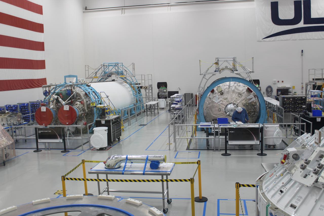
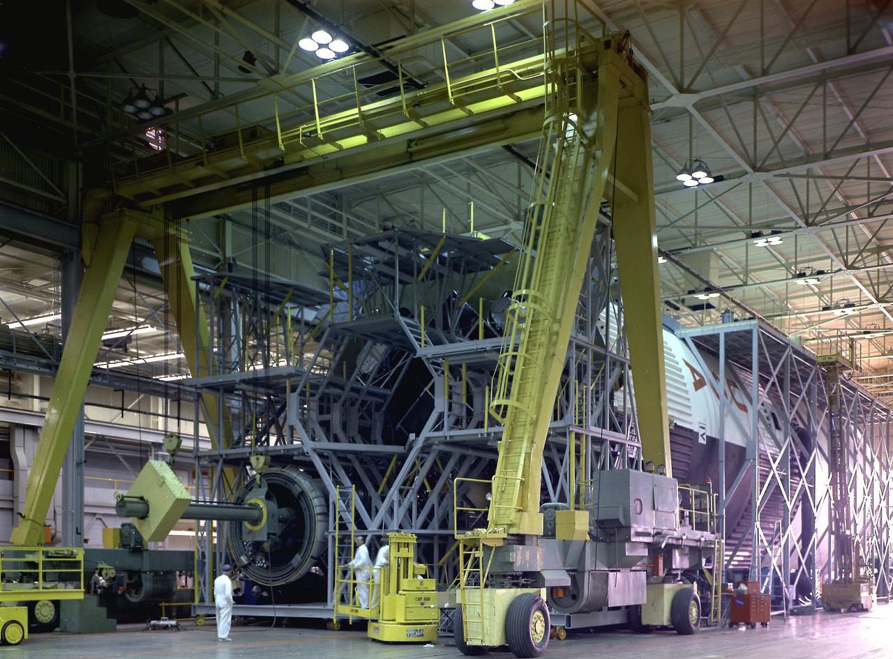
Two United Launch Alliance (ULA) Atlas V dual engine Centaur upper stages are in production in ULA's factory in Decatur, Alabama on March 1, 2019. One is for Boeing’s Crew Flight Test on the CST-100 Starliner, and the other will be used for the first crew rotation mission on the Starliner. One of the Centaur upper stages will be assembled to the first stage booster. They will be shipped aboard the company’s Mariner cargo ship to NASA’s Kennedy Space Center in Florida. Starliner and the Atlas V rockets that will launch the spacecraft, are key to restoring the nation’s capability to send astronauts to the space station from U.S. soil with NASA’s Commercial Crew Program. NASA astronauts Mike Fincke and Nicole Mann, and Boeing astronaut Chris Ferguson will launch to the space station aboard the Starliner for the Crew Flight Test.
COLD FLOW - Liquid oxygen runs through the piping on Stennis Space Center's A-1 Test Stand on Dec. 18 to test the ability of the J-2X engine's Powerpack 1A to withstand the temperature change and pressure. Just visible above and to the right of the test article's nozzle is a frosty pipe, indicating the supercold fuel is flowing as it should.
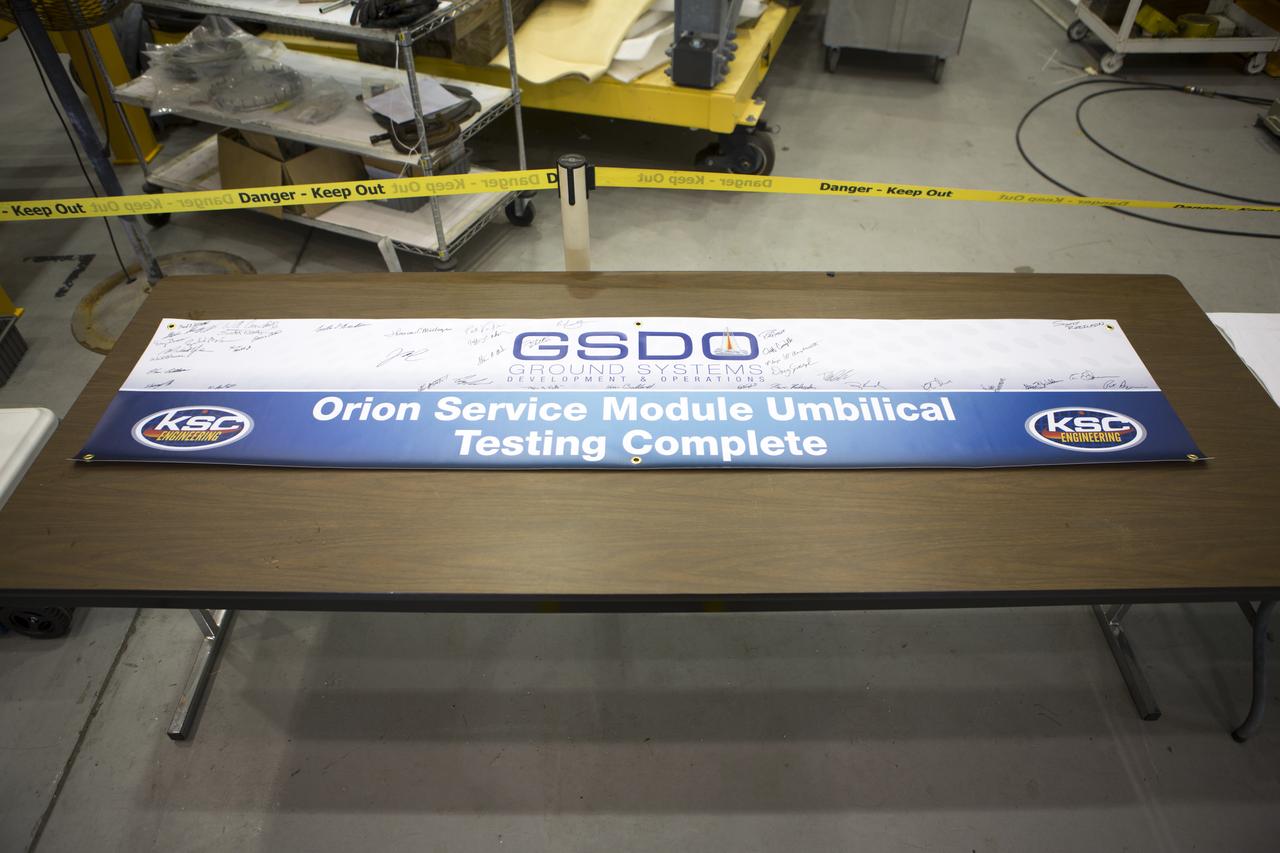
Testing of the Orion Service Module Umbilical (OSMU) was completed at the Launch Equipment Test Facility at NASA’s Kennedy Space Center in Florida. The OSMU was attached to Vehicle Motion Simulator 1 for a series of simulated launch tests to validate it for installation on the mobile launcher. The test team signed a special banner during an event to mark the end of testing. The mobile launcher tower will be equipped with a number of lines, called umbilicals that will connect to the Space Launch System rocket and Orion spacecraft for Exploration Mission-1 (EM-1). The OSMU will be located high on the mobile launcher tower and, prior to launch, will transfer liquid coolant for the electronics and air for the Environmental Control System to the Orion service module that houses these critical systems to support the spacecraft. Kennedy's Engineering Directorate is providing support to the Ground Systems Development and Operations Program for testing of the OSMU. EM-1 is scheduled to launch in 2018.
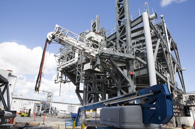
Testing of the Orion Service Module Umbilical (OSMU) was completed at the Launch Equipment Test Facility at NASA’s Kennedy Space Center in Florida. The OSMU was attached to Vehicle Motion Simulator 1 for a series of simulated launch tests to validate it for installation on the mobile launcher. The mobile launcher tower will be equipped with a number of lines, called umbilicals that will connect to the Space Launch System rocket and Orion spacecraft for Exploration Mission-1 (EM-1). The OSMU will be located high on the mobile launcher tower and, prior to launch, will transfer liquid coolant for the electronics and air for the Environmental Control System to the Orion service module that houses these critical systems to support the spacecraft. Kennedy's Engineering Directorate is providing support to the Ground Systems Development and Operations Program for testing of the OSMU. EM-1 is scheduled to launch in 2018.
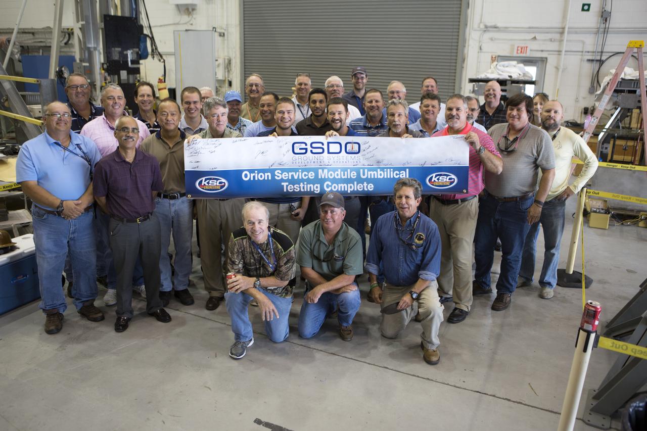
Testing of the Orion Service Module Umbilical (OSMU) was completed at the Launch Equipment Test Facility at NASA’s Kennedy Space Center in Florida. The OSMU was attached to Vehicle Motion Simulator 1 for a series of simulated launch tests to validate it for installation on the mobile launcher. The test team gathered with a special banner during an event to mark the end of testing. The mobile launcher tower will be equipped with a number of lines, called umbilicals that will connect to the Space Launch System rocket and Orion spacecraft for Exploration Mission-1 (EM-1). The OSMU will be located high on the mobile launcher tower and, prior to launch, will transfer liquid coolant for the electronics and air for the Environmental Control System to the Orion service module that houses these critical systems to support the spacecraft. Kennedy's Engineering Directorate is providing support to the Ground Systems Development and Operations Program for testing of the OSMU. EM-1 is scheduled to launch in 2018.

Testing of the Orion Service Module Umbilical (OSMU) was completed at the Launch Equipment Test Facility at NASA’s Kennedy Space Center in Florida. The OSMU was attached to Vehicle Motion Simulator 1 for a series of simulated launch tests to validate it for installation on the mobile launcher. One of the test team members signs a banner during an event to mark the end of testing. The mobile launcher tower will be equipped with a number of lines, called umbilicals that will connect to the Space Launch System rocket and Orion spacecraft for Exploration Mission-1 (EM-1). The OSMU will be located high on the mobile launcher tower and, prior to launch, will transfer liquid coolant for the electronics and air for the Environmental Control System to the Orion service module that houses these critical systems to support the spacecraft. Kennedy's Engineering Directorate is providing support to the Ground Systems Development and Operations Program for testing of the OSMU. EM-1 is scheduled to launch in 2018.
Testing of the Orion Service Module Umbilical (OSMU) was completed at the Launch Equipment Test Facility at NASA’s Kennedy Space Center in Florida. The OSMU was attached to Vehicle Motion Simulator 1 for a series of simulated launch tests to validate it for installation on the mobile launcher. The test team gathered for an event to mark the end of testing. The mobile launcher tower will be equipped with a number of lines, called umbilicals that will connect to the Space Launch System rocket and Orion spacecraft for Exploration Mission-1 (EM-1). The OSMU will be located high on the mobile launcher tower and, prior to launch, will transfer liquid coolant for the electronics and air for the Environmental Control System to the Orion service module that houses these critical systems to support the spacecraft. Kennedy's Engineering Directorate is providing support to the Ground Systems Development and Operations Program for testing of the OSMU. EM-1 is scheduled to launch in 2018.
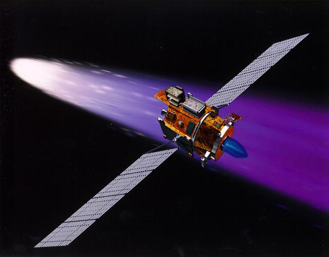
NASA's New Millennium Deep Space 1 spacecraft approaching the comet 19P/Borrelly. With its primary mission to serve as a technology demonstrator--testing ion propulsion and 11 other advanced technologies--successfully completed in September 1999, Deep Space 1 is now headed for a risky, exciting rendezvous with Comet Borrelly. NASA extended the mission, taking advantage of the ion propulsion and other systems to target the daring encounter with the comet in September 2001. Once a sci-fi dream, the ion propulsion engine has powered the spacecraft for over 12,000 hours. Another onboard experiment includes software that tracks celestial bodies so the spacecraft can make its own navigation decisions without the intervention of ground controllers. The first flight in NASA's New Millennium Program, Deep Space 1 was launched October 24, 1998 aboard a Boeing Delta 7326 rocket from Cape Canaveral Air Station, FL. Deep Space 1 successfully completed and exceeded its mission objectives in July 1999 and flew by a near-Earth asteroid, Braille (1992 KD), in September 1999. http://photojournal.jpl.nasa.gov/catalog/PIA04604
This photograph depicts a dramatic view of the first test firing of all five F-1 engines for the Saturn V S-IC stage at the Marshall Space Flight Center. The testing lasted a full duration of 6.5 seconds. It also marked the first test performed in the new S-IC static test stand and the first test using the new control blockhouse. The S-IC stage is the first stage, or booster, of a 364-foot long rocket that ultimately took astronauts to the Moon. Operating at maximum power, all five of the engines produced 7,500,000 pounds of thrust. Required to hold down the brute force of a 7,500,000-pound thrust, the S-IC static test stand was designed and constructed with the strength of hundreds of tons of steel and cement, planted down to bedrock 40 feet below ground level. The structure was topped by a crane with a 135-foot boom. With the boom in the up position, the stand was given an overall height of 405 feet, placing it among the highest structures in Alabama at the time. When the Saturn V S-IC first stage was placed upright in the stand , the five F-1 engine nozzles pointed downward on a 1,900 ton, water-cooled deflector. To prevent melting damage, water was sprayed through small holes in the deflector at the rate 320,000 gallons per minute.
This photograph depicts a view of the test firing of all five F-1 engines for the Saturn V S-IC test stage at the Marshall Space Flight Center. The S-IC stage is the first stage, or booster, of a 364-foot long rocket that ultimately took astronauts to the Moon. Operating at maximum power, all five of the engines produced 7,500,000 pounds of thrust. The S-IC Static Test Stand was designed and constructed with the strength of hundreds of tons of steel and cement, planted down to bedrock 40 feet below ground level, and was required to hold down the brute force of the 7,500,000-pound thrust. The structure was topped by a crane with a 135-foot boom. With the boom in the up position, the stand was given an overall height of 405 feet, placing it among the highest structures in Alabama at the time. When the Saturn V S-IC first stage was placed upright in the stand , the five F-1 engine nozzles pointed downward on a 1,900-ton, water-cooled deflector. To prevent melting damage, water was sprayed through small holes in the deflector at the rate 320,000 gallons per minutes.
This photograph depicts a view of the test firing of all five F-1 engines for the Saturn V S-IC test stage at the Marshall Space Flight Center. The S-IC stage is the first stage, or booster, of a 364-foot long rocket that ultimately took astronauts to the Moon. Operating at maximum power, all five of the engines produced 7,500,000 pounds of thrust. The S-IC Static Test Stand was designed and constructed with the strength of hundreds of tons of steel and cement, planted down to bedrock 40 feet below ground level, and was required to hold down the brute force of the 7,500,000-pound thrust. The structure was topped by a crane with a 135-foot boom. With the boom in the up position, the stand was given an overall height of 405 feet, placing it among the highest structures in Alabama at the time. When the Saturn V S-IC first stage was placed upright in the stand , the five F-1 engine nozzles pointed downward on a 1,900-ton, water-cooled deflector. To prevent melting damage, water was sprayed through small holes in the deflector at the rate 320,000 gallons per minutes
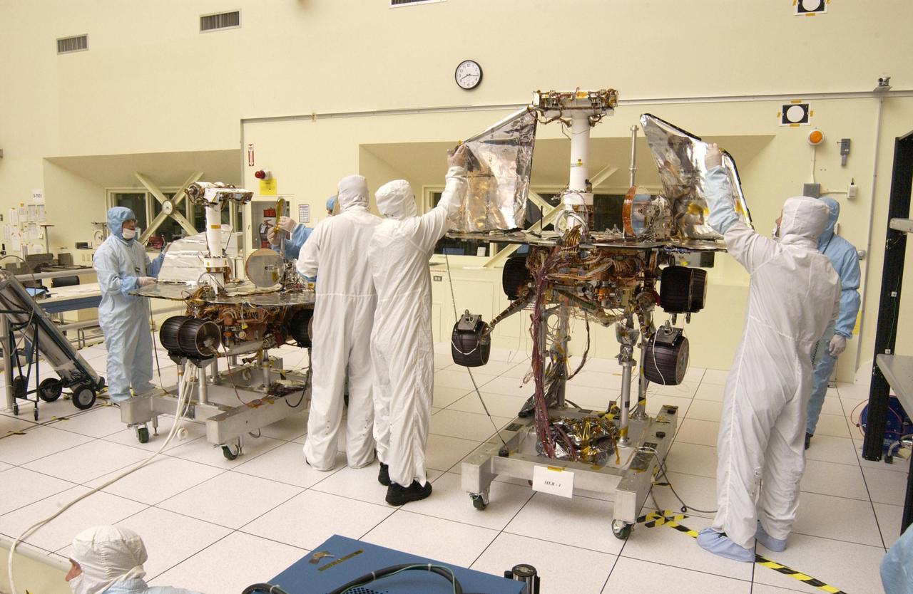
JPL engineers hand-deploying the solar arrays that provide the electrical power on NASA Mars Exploration Rover 1.
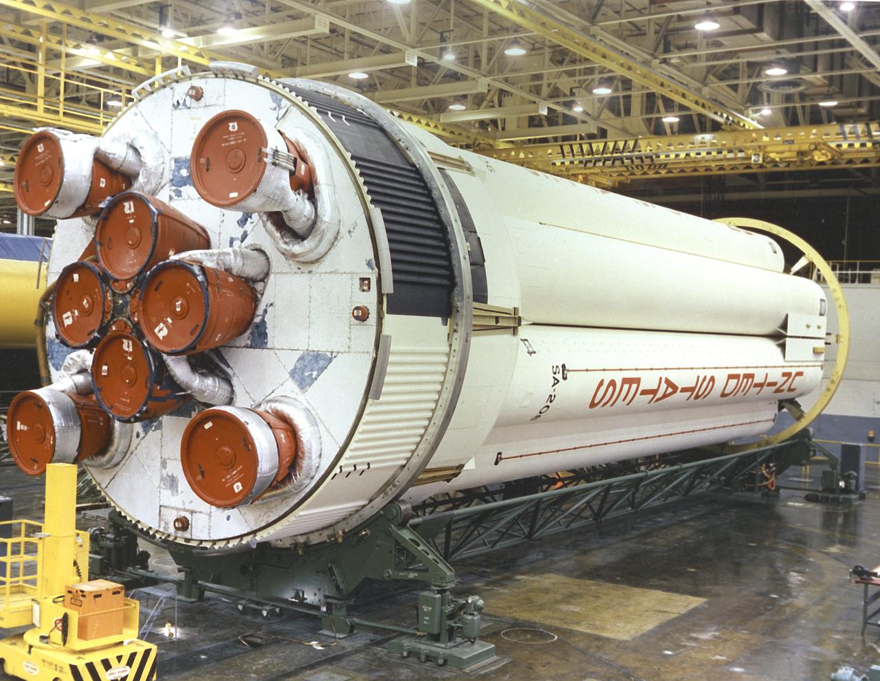
The Saturn 1B S-IB (first) stage being prepared for shipment at Michoud Assembly Facility (MAF), near New Orleans, Louisiana. Developed by the Marshall Space Flight Center and built by the Chrysler Corporation at MAF, the S-IB stage utilized the eight H-1 engines and each produced 200,000 pounds of thrust, a combined thrust of 1,600,000 pounds.
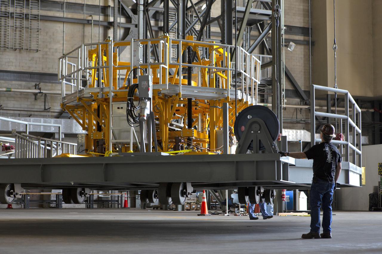
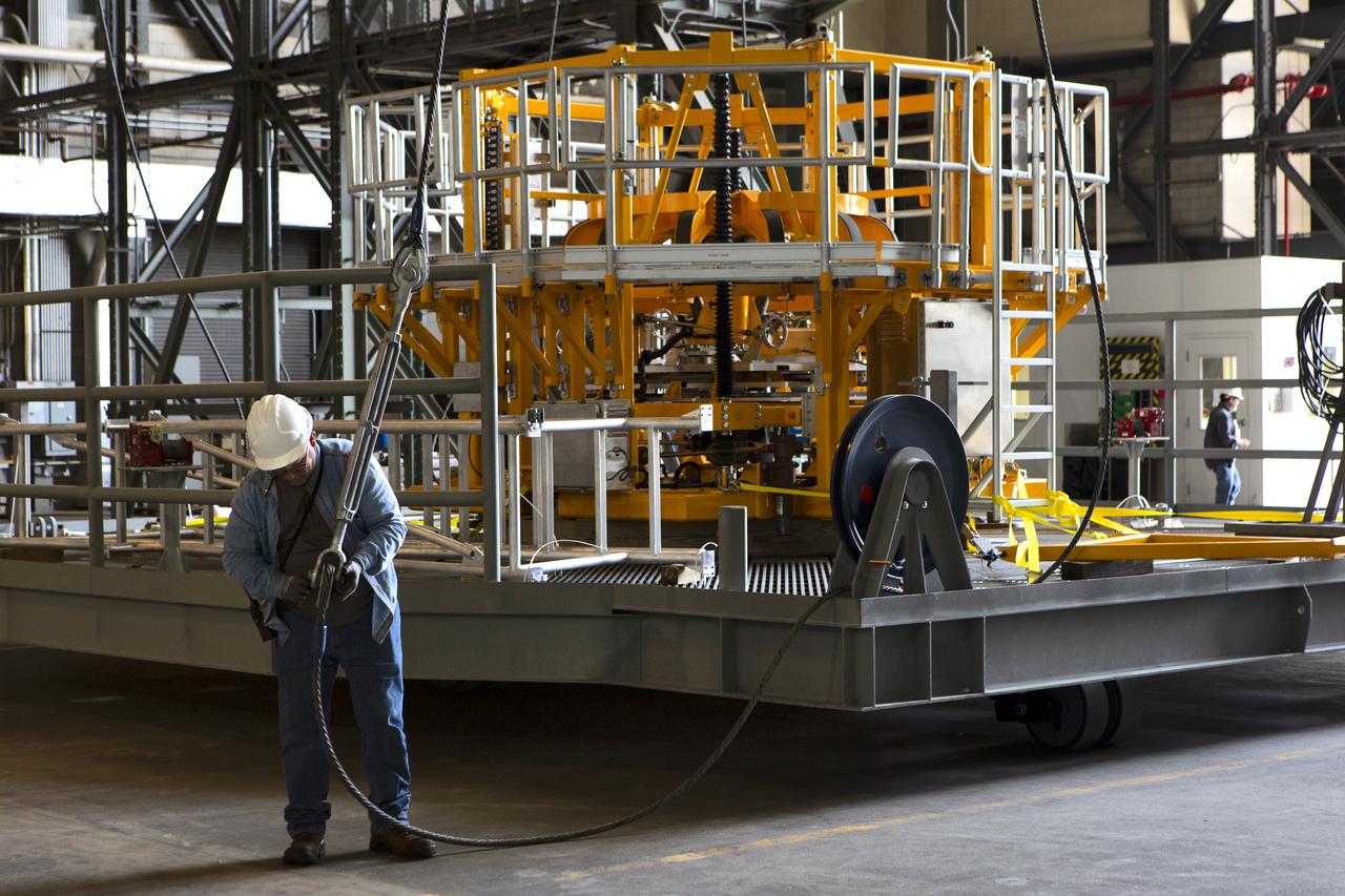
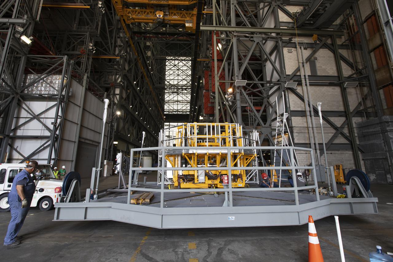
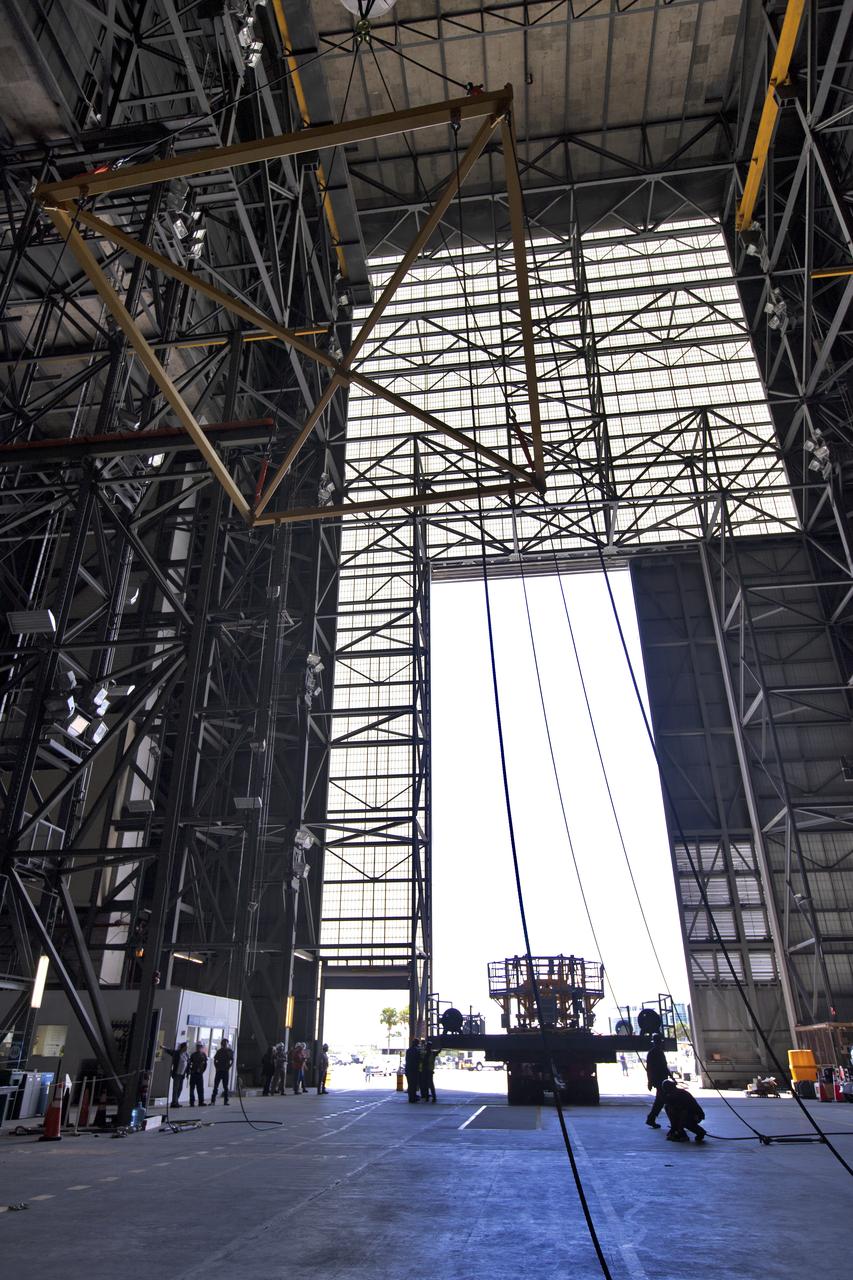
The engine vertical installer for NASA’s Space Launch System (SLS) is inside the Vehicle Assembly at NASA’s Kennedy Space Center in Florida on April 25, 2019. The engine installer will be lifted up by crane for transfer to High Bay 3. The engine installer arrived from the manufacturer, Precision Fabrication and Cleaning in Canaveral Groves, Florida. The new ground support equipment will be ready for preflight processing in the event one of the four RS-25 engines on the core stage of the SLS rocket needs to be replaced. During launch of the SLS and Orion spacecraft, the four core stage engines will provide the thrust needed to lift the rocket and Orion spacecraft off Launch Pad 39B at Kennedy for Exploration Mission-1. The uncrewed Orion will travel on a three-week test mission thousands of miles beyond the Moon and back to Earth for a splashdown in the Pacific Ocean.
The engine vertical installer for NASA’s Space Launch System (SLS) is inside the Vehicle Assembly at NASA’s Kennedy Space Center in Florida on April 25, 2019. The engine installer is being lifted up by crane for transfer to High Bay 3. The engine installer arrived from the manufacturer, Precision Fabrication and Cleaning in Canaveral Groves, Florida. The new ground support equipment will be ready for preflight processing in the event one of the four RS-25 engines on the core stage of the SLS rocket needs to be replaced. During launch of the SLS and Orion spacecraft, the four core stage engines will provide the thrust needed to lift the rocket and Orion spacecraft off Launch Pad 39B at Kennedy for Exploration Mission-1. The uncrewed Orion will travel on a three-week test mission thousands of miles beyond the Moon and back to Earth for a splashdown in the Pacific Ocean.
The engine vertical installer for NASA’s Space Launch System (SLS) is inside the Vehicle Assembly at NASA’s Kennedy Space Center in Florida on April 25, 2019. Preparations are underway to lift the engine installer up and into High Bay 3. The engine installer arrived from the manufacturer, Precision Fabrication and Cleaning in Canaveral Groves, Florida. The new ground support equipment will be ready for preflight processing in the event one of the four RS-25 engines on the core stage of the SLS rocket needs to be replaced. During launch of the SLS and Orion spacecraft, the four core stage engines will provide the thrust needed to lift the rocket and Orion spacecraft off Launch Pad 39B at Kennedy for Exploration Mission-1. The uncrewed Orion will travel on a three-week test mission thousands of miles beyond the Moon and back to Earth for a splashdown in the Pacific Ocean.
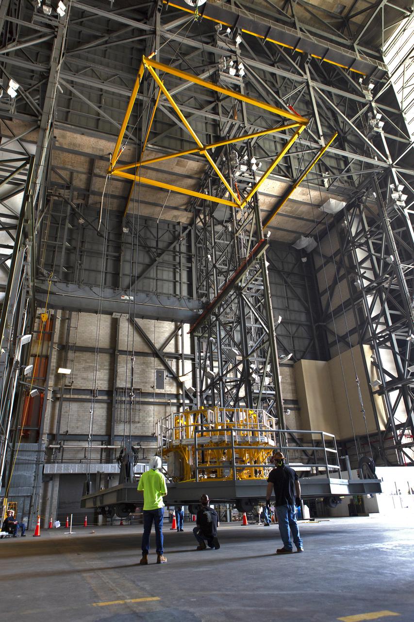
The engine vertical installer for NASA’s Space Launch System (SLS) is inside the Vehicle Assembly at NASA’s Kennedy Space Center in Florida on April 25, 2019. The engine installer is being lifted up by crane for transfer to High Bay 3. The engine installer arrived from the manufacturer, Precision Fabrication and Cleaning in Canaveral Groves, Florida. The new ground support equipment will be ready for preflight processing in the event one of the four RS-25 engines on the core stage of the SLS rocket needs to be replaced. During launch of the SLS and Orion spacecraft, the four core stage engines will provide the thrust needed to lift the rocket and Orion spacecraft off Launch Pad 39B at Kennedy for Exploration Mission-1. The uncrewed Orion will travel on a three-week test mission thousands of miles beyond the Moon and back to Earth for a splashdown in the Pacific Ocean.
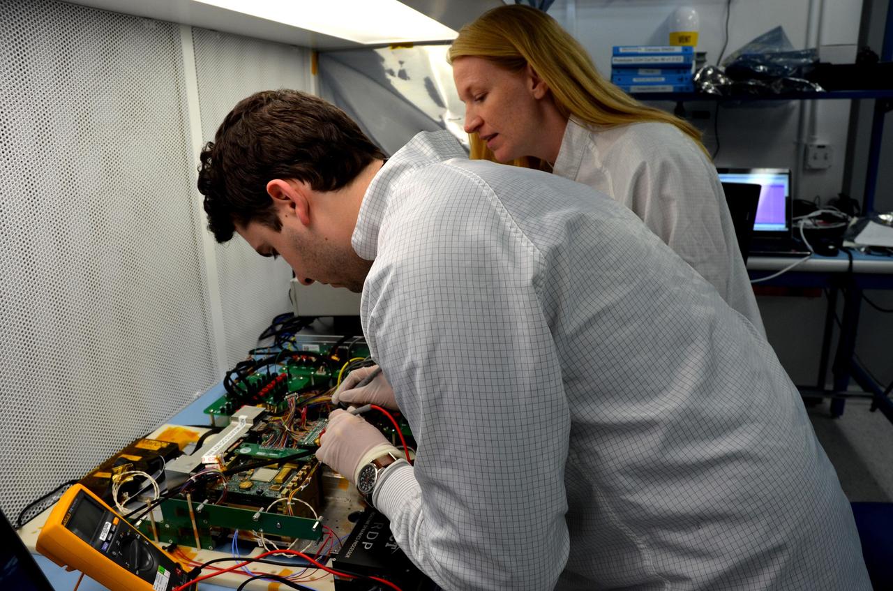
Engineers for NASA's MarCO (Mars Cube One) technology demonstration inspect the MarCO test bed, which contains components that are identical to those built for a flight to Mars. Cody Colley, left, MarCO integration and test deputy, and Shannon Statham, MarCO integration and test lead, are on the team at NASA's Jet Propulsion Laboratory, Pasadena, California, preparing twin MarCO CubeSats. The briefcase-size MarCO twins were designed to ride along with NASA's next Mars lander, InSight. Its planned March 2016 launch was suspended. InSight -- an acronym for Interior Exploration using Seismic Investigations, Geodesy and Heat Transport -- will study the interior of Mars to improve understanding of the processes that formed and shaped rocky planets, including Earth. Note: After thorough examination, NASA managers have decided to suspend the planned March 2016 launch of the Interior Exploration using Seismic Investigations Geodesy and Heat Transport (InSight) mission. The decision follows unsuccessful attempts to repair a leak in a section of the prime instrument in the science payload. http://photojournal.jpl.nasa.gov/catalog/PIA20341
The engine vertical installer for NASA’s Space Launch System (SLS) arrives at the Vehicle Assembly at NASA’s Kennedy Space Center in Florida on April 25, 2019. The engine installer arrived from the manufacturer, Precision Fabrication and Cleaning in Canaveral Groves, Florida. The new ground support equipment will be ready for preflight processing in the event one of the four RS-25 engines on the core stage of the SLS rocket needs to be replaced. During launch of the SLS and Orion spacecraft, the four core stage engines will provide the thrust needed to lift the rocket and Orion spacecraft off Launch Pad 39B at Kennedy for Exploration Mission-1. The uncrewed Orion will travel on a three-week test mission thousands of miles beyond the Moon and back to Earth for a splashdown in the Pacific Ocean.
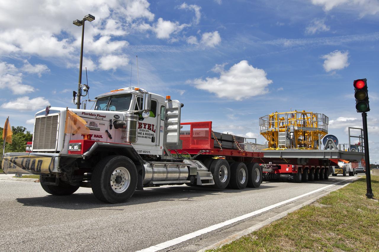
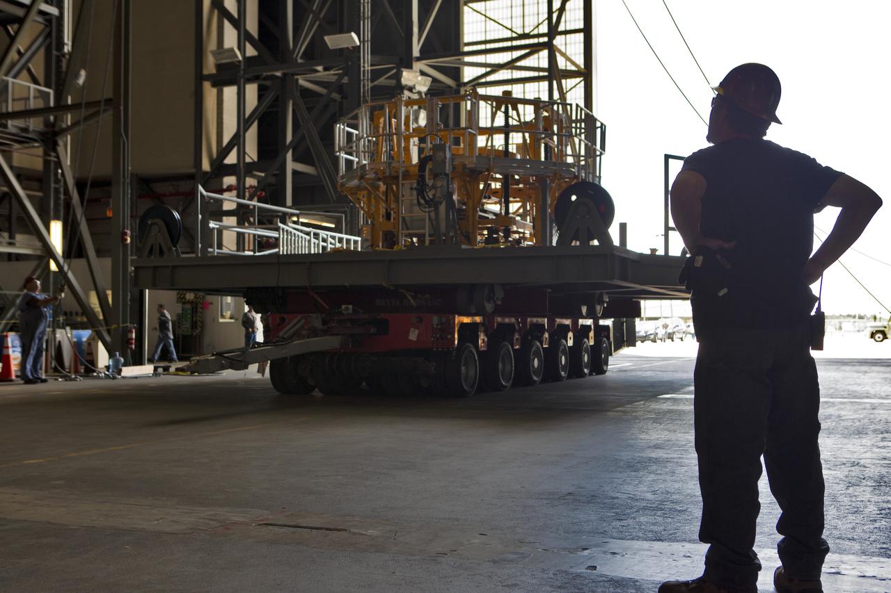
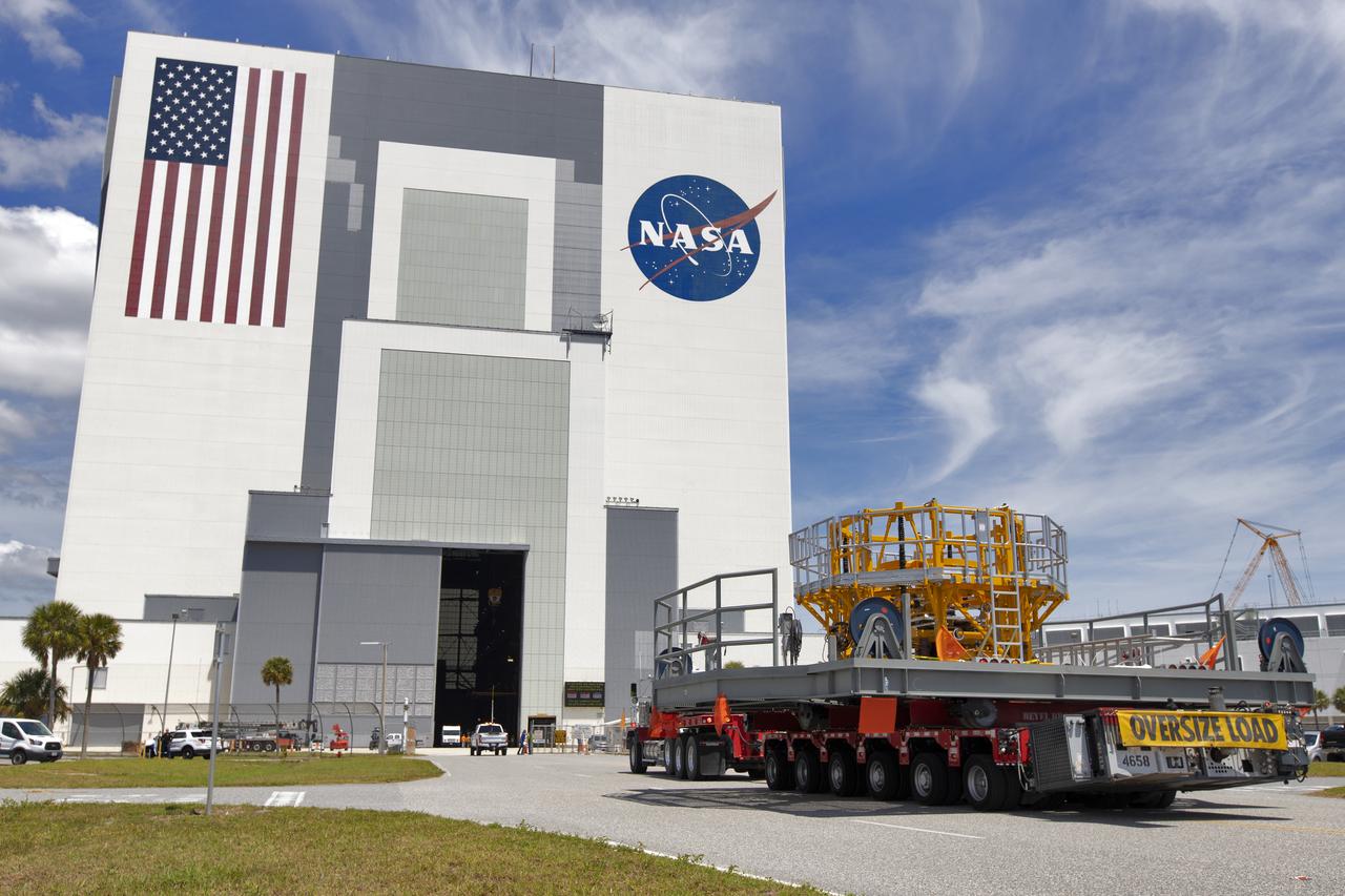
The engine vertical installer for NASA’s Space Launch System (SLS) arrives by large transport truck at NASA’s Kennedy Space Center in Florida on April 25, 2019. The engine installer arrived from the manufacturer, Precision Fabrication and Cleaning in Canaveral Groves, Florida. The new ground support equipment will be delivered to the Vehicle Assembly where it will be ready for preflight processing in the event one of the four RS-25 engines on the core stage of the SLS rocket needs to be replaced. During launch of the SLS and Orion spacecraft, the four core stage engines will provide the thrust needed to lift the rocket and Orion spacecraft off Launch Pad 39B at Kennedy for Exploration Mission-1. The uncrewed Orion will travel on a three-week test mission thousands of miles beyond the Moon and back to Earth for a splashdown in the Pacific Ocean.

The engine vertical installer for NASA’s Space Launch System (SLS) arrives inside the Vehicle Assembly at NASA’s Kennedy Space Center in Florida on April 25, 2019. The engine installer arrived from the manufacturer, Precision Fabrication and Cleaning in Canaveral Groves, Florida. The new ground support equipment will be ready for preflight processing in the event one of the four RS-25 engines on the core stage of the SLS rocket needs to be replaced. During launch of the SLS and Orion spacecraft, the four core stage engines will provide the thrust needed to lift the rocket and Orion spacecraft off Launch Pad 39B at Kennedy for Exploration Mission-1. The uncrewed Orion will travel on a three-week test mission thousands of miles beyond the Moon and back to Earth for a splashdown in the Pacific Ocean.
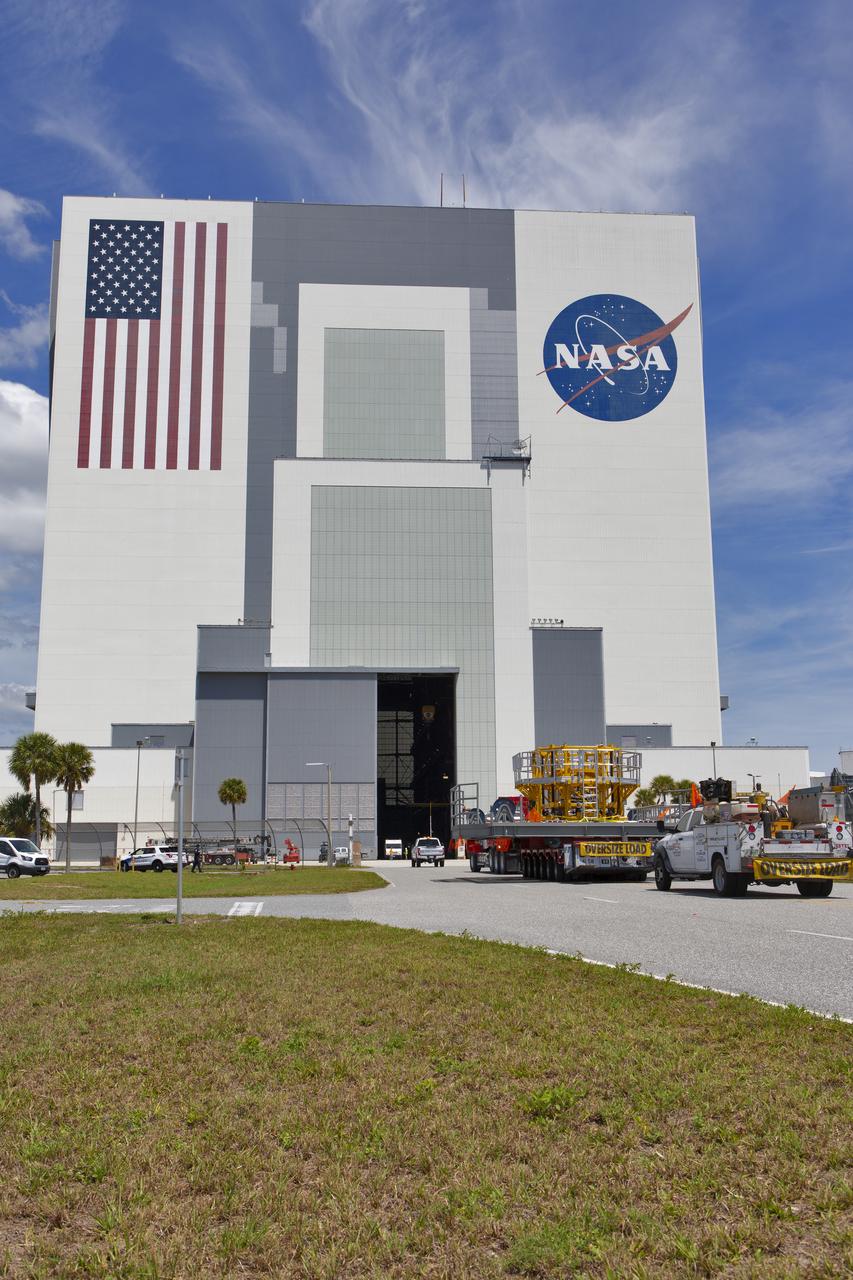
The engine vertical installer for NASA’s Space Launch System (SLS) arrives by large transport truck at the Vehicle Assembly Building at NASA’s Kennedy Space Center in Florida on April 25, 2019. The engine installer arrived from the manufacturer, Precision Fabrication and Cleaning in Canaveral Groves, Florida. The new ground support equipment will be ready for preflight assembly in the event one of the four RS-25 engines on the core stage of the SLS rocket needs to be replaced. During launch of the SLS and Orion spacecraft, the four core stage engines will provide the thrust needed to lift the rocket and Orion spacecraft off Launch Pad 39B at Kennedy for Exploration Mission-1. The uncrewed Orion will travel on a three-week test mission thousands of miles beyond the Moon and back to Earth for a splashdown in the Pacific Ocean.
The engine vertical installer for NASA’s Space Launch System (SLS) arrives inside the Vehicle Assembly at NASA’s Kennedy Space Center in Florida on April 25, 2019. The engine installer arrived from the manufacturer, Precision Fabrication and Cleaning in Canaveral Groves, Florida. The new ground support equipment will be ready for preflight processing in the event one of the four RS-25 engines on the core stage of the SLS rocket needs to be replaced. During launch of the SLS and Orion spacecraft, the four core stage engines will provide the thrust needed to lift the rocket and Orion spacecraft off Launch Pad 39B at Kennedy for Exploration Mission-1. The uncrewed Orion will travel on a three-week test mission thousands of miles beyond the Moon and back to Earth for a splashdown in the Pacific Ocean.
The engine vertical installer for NASA’s Space Launch System (SLS) arrives inside the Vehicle Assembly at NASA’s Kennedy Space Center in Florida on April 25, 2019. The engine installer arrived from the manufacturer, Precision Fabrication and Cleaning in Canaveral Groves, Florida. The new ground support equipment will be ready for preflight processing in the event one of the four RS-25 engines on the core stage of the SLS rocket needs to be replaced. During launch of the SLS and Orion spacecraft, the four core stage engines will provide the thrust needed to lift the rocket and Orion spacecraft off Launch Pad 39B at Kennedy for Exploration Mission-1. The uncrewed Orion will travel on a three-week test mission thousands of miles beyond the Moon and back to Earth for a splashdown in the Pacific Ocean.