
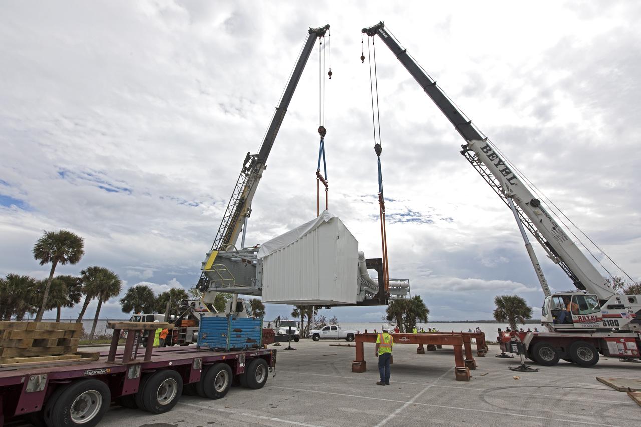
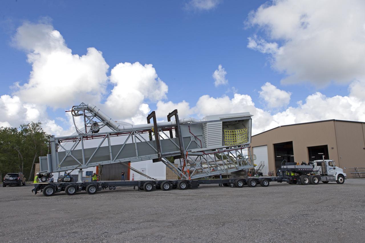
The Mobile Fabrication Shop was received at NASA Armstrong on February 7, 2022 as part of the Robotics Alliance Program based at NASA’s Johnson Space Center. This view shows the fabrication equipment housed inside the trailer that attends robotics competitions to help students during their robotics competitions.
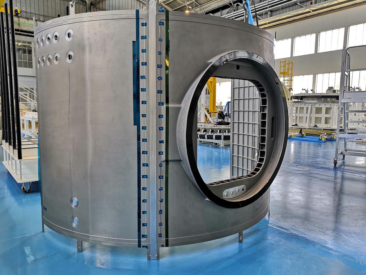
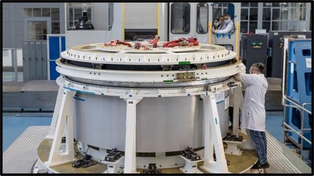
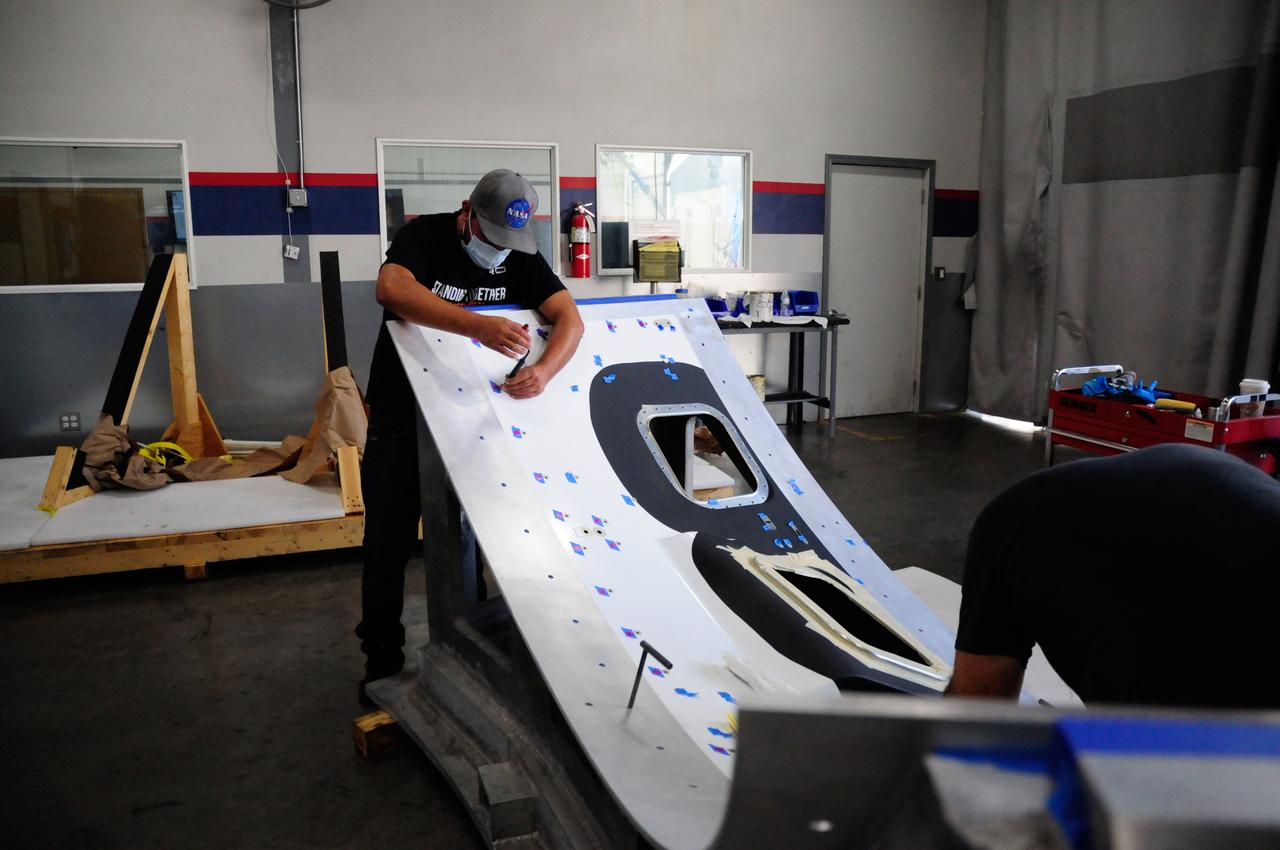
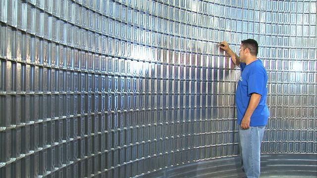
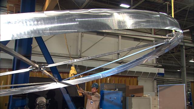
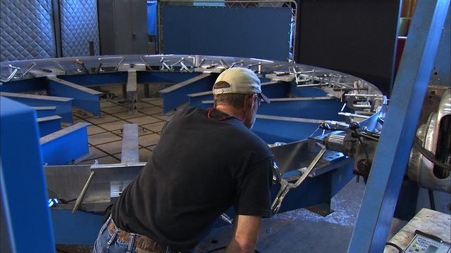
Northrop Grumman and subcontractor Thales Alenia Space complete fabrication work on the Habitation and Logistics Outpost (HALO) module, one of two of the Gateway Space Station's habitation elements where astronauts will live and work in lunar orbit during deep space Artemis missions.
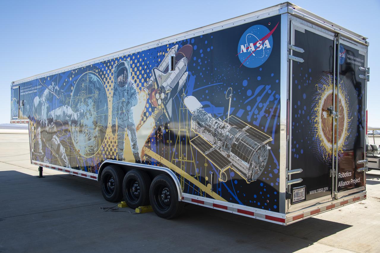
The Mobile Fabrication Shop was received at NASA Armstrong on February 7, 2022 as part of the Robotics Alliance Program based at NASA’s Johnson Space Center. This view shows the side and rear of the wrapped trailer that attends robotics competitions to help students during their robotics competitions.
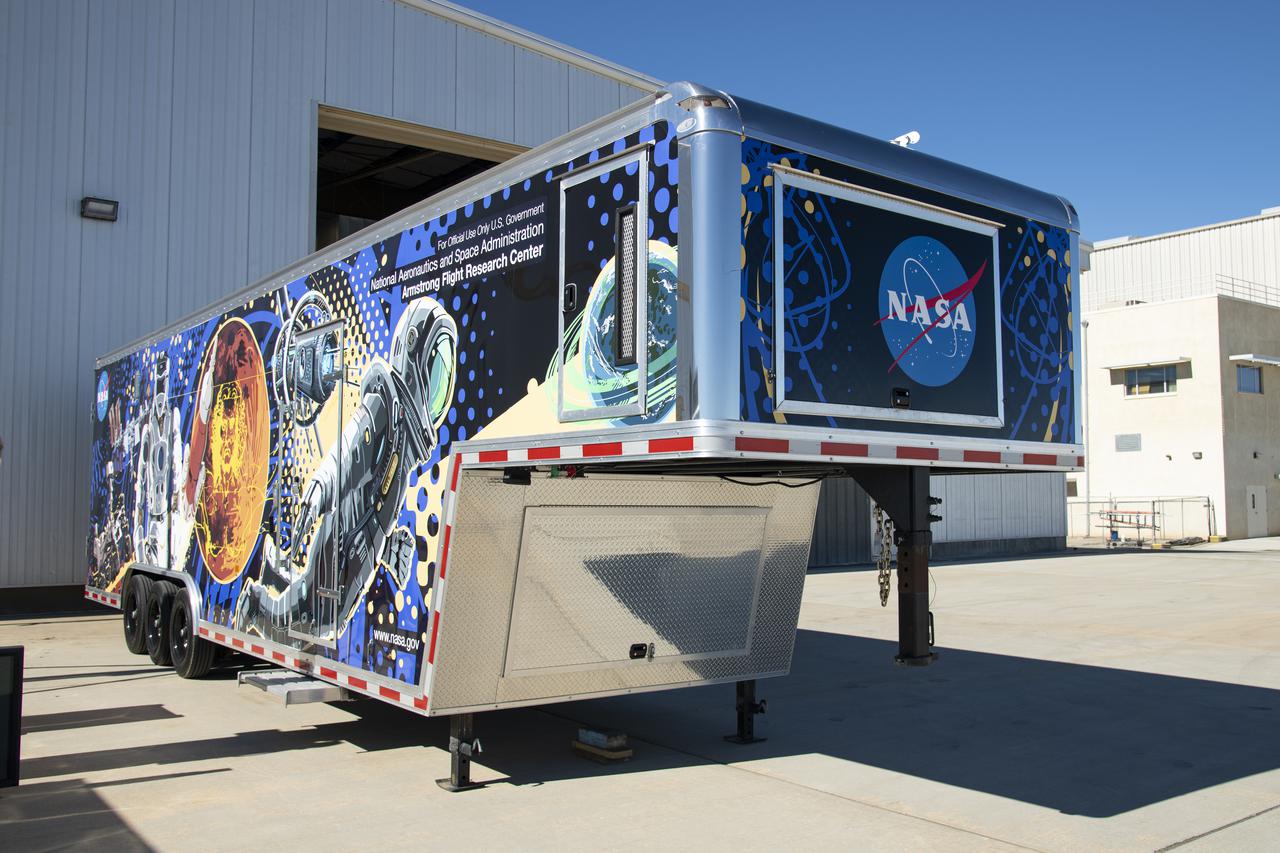
The Mobile Fabrication Shop was received at NASA Armstrong on February 7, 2022 as part of the Robotics Alliance Program based at NASA’s Johnson Space Center. This view shows the front of the wrapped trailer that attends robotics competitions to help students during their robotics competitions.
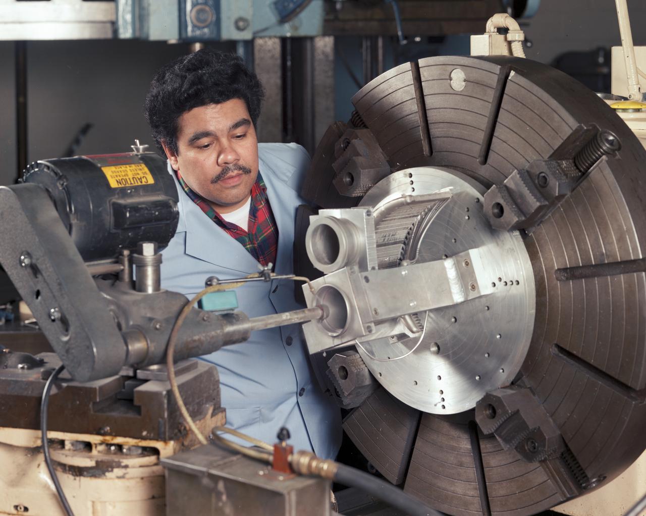
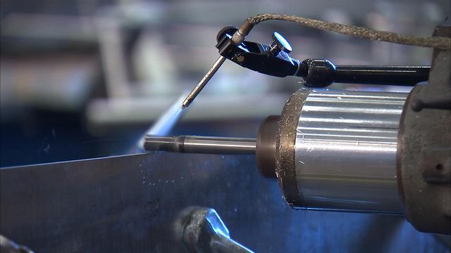
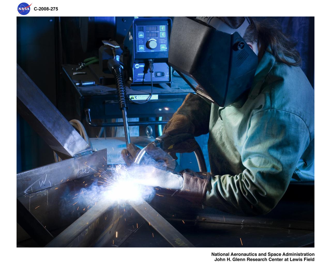
Fabrication of Stirling Engine Cylinder Test Hardware in the Machine Shop
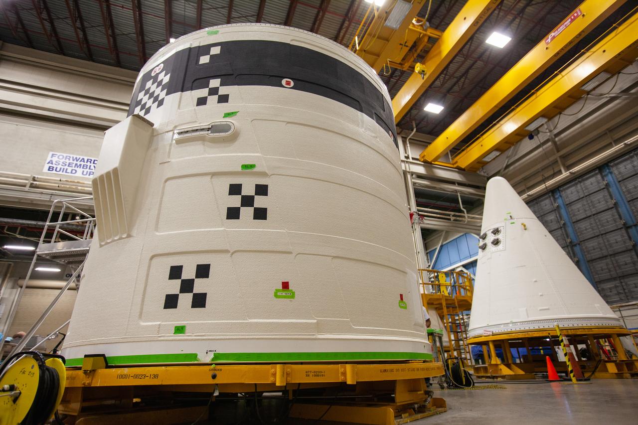
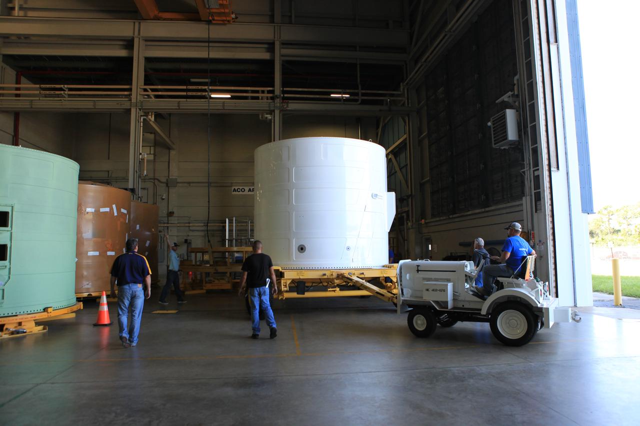
The forward skirt for one of the Space Launch System’s (SLS) two solid boosters is inside the Booster Fabrication Facility at NASA’s Kennedy Space Center in Florida on Oct. 16, 2019. Segments of the boosters are being inspected and prepared for Artemis I, the agency’s first uncrewed flight of Orion atop the SLS. The forward skirt houses booster avionics that communicate with the SLS avionics to monitor booster conditions and steer the booster exhaust nozzle.
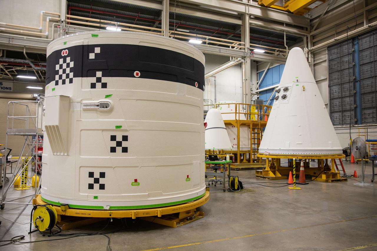
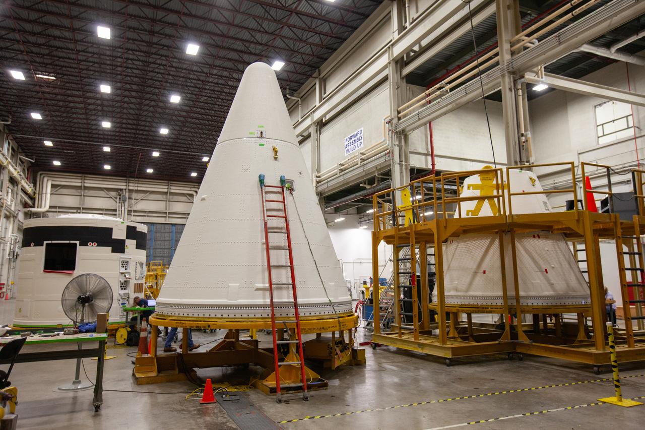
A forward skirt and two nose cones for the Space Launch System’s (SLS) two solid boosters are in view inside the Booster Fabrication Facility at NASA’s Kennedy Space Center in Florida on Oct. 16, 2019. Segments of the boosters are being inspected and prepared for Artemis I, the agency’s first uncrewed flight of Orion atop the SLS. The forward skirt houses booster avionics that communicate with the SLS avionics to monitor booster conditions and steer the booster exhaust nozzle. The nose cone, along with a frustrum, will serve as the aerodynamic fairing for the boosters during launch.
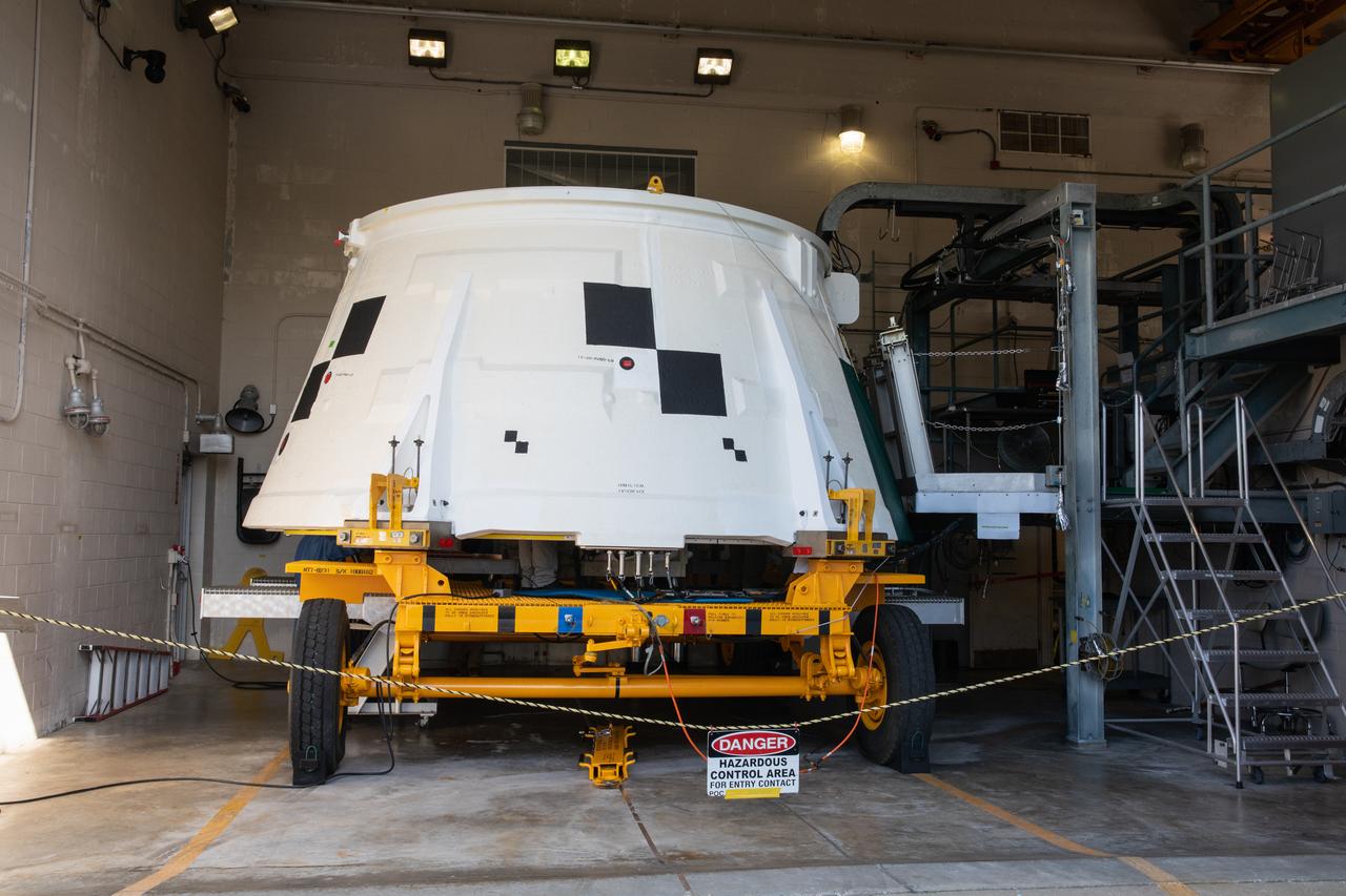
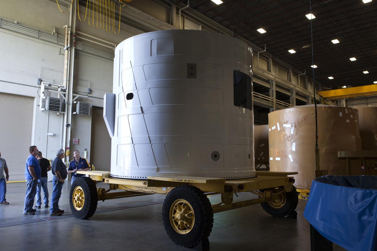
The aft skirt for one of the Space Launch System’s (SLS) two solid rocket boosters is inside the Booster Fabrication Facility at NASA’s Kennedy Space Center in Florida on Oct. 16, 2019. Segments of the boosters are being inspected and prepared for Artemis I, the agency’s first uncrewed flight of Orion atop the SLS. The aft skirts contain the thrust vector control system that steers the booster’s nozzles based on commands from the booster avionics during launch.
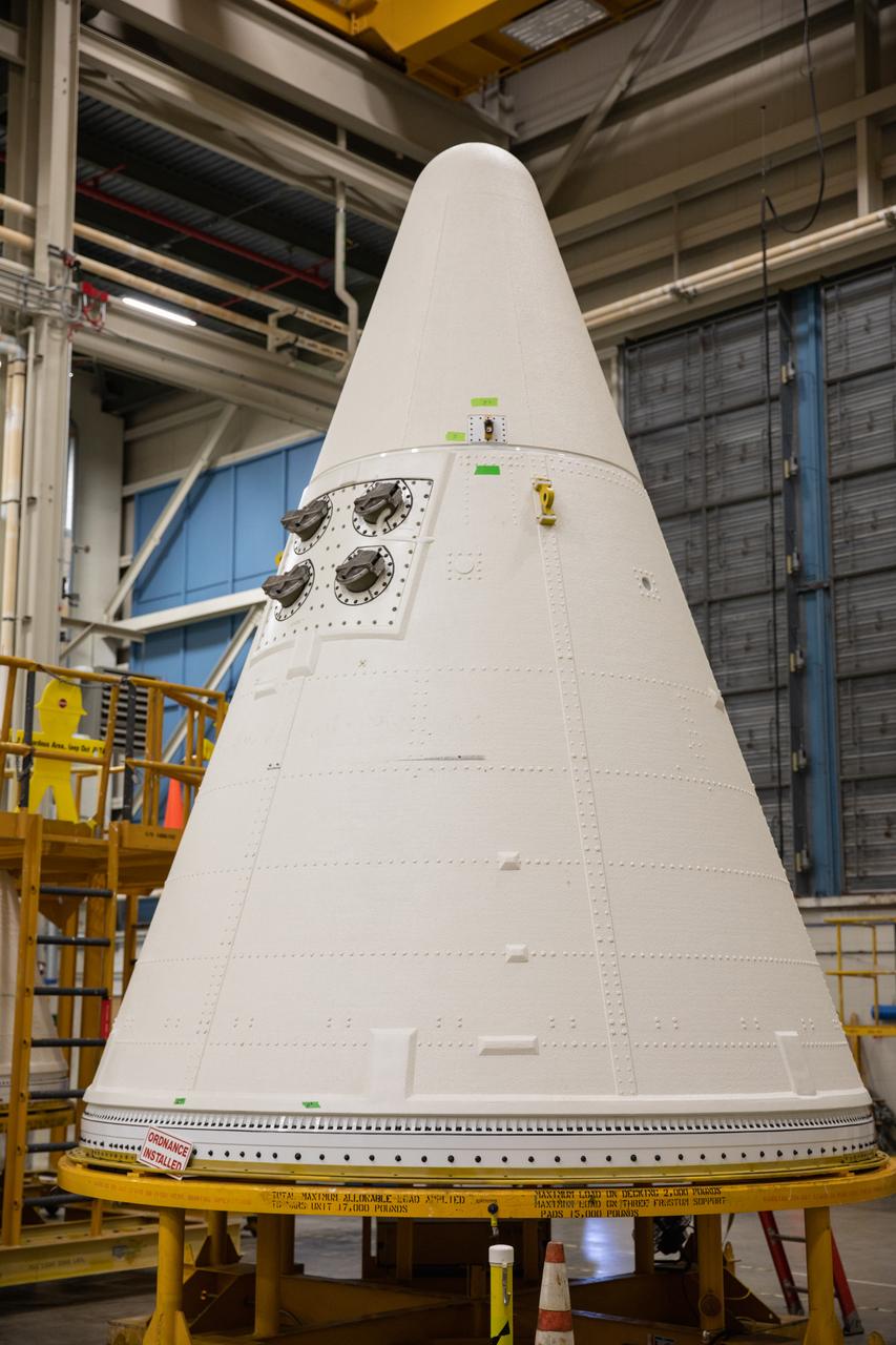
A nose cone for one of the Space Launch System’s (SLS) two solid rocket boosters is inside the Booster Fabrication Facility at NASA’s Kennedy Space Center in Florida on Oct. 16, 2019. Segments of the boosters are being inspected and prepared for Artemis I, the agency’s first uncrewed flight of Orion atop the SLS. The nose cone, along with a frustrum, will serve as the aerodynamic fairing for the boosters during launch.
A nose cone for one of the Space Launch System’s (SLS) two solid rocket boosters is inside the Booster Fabrication Facility at NASA’s Kennedy Space Center in Florida on Oct. 16, 2019. Segments of the boosters are being inspected and prepared for Artemis I, the agency’s first uncrewed flight of Orion atop the SLS. The nose cone, along with a frustrum, will serve as the aerodynamic fairing for the boosters during launch.
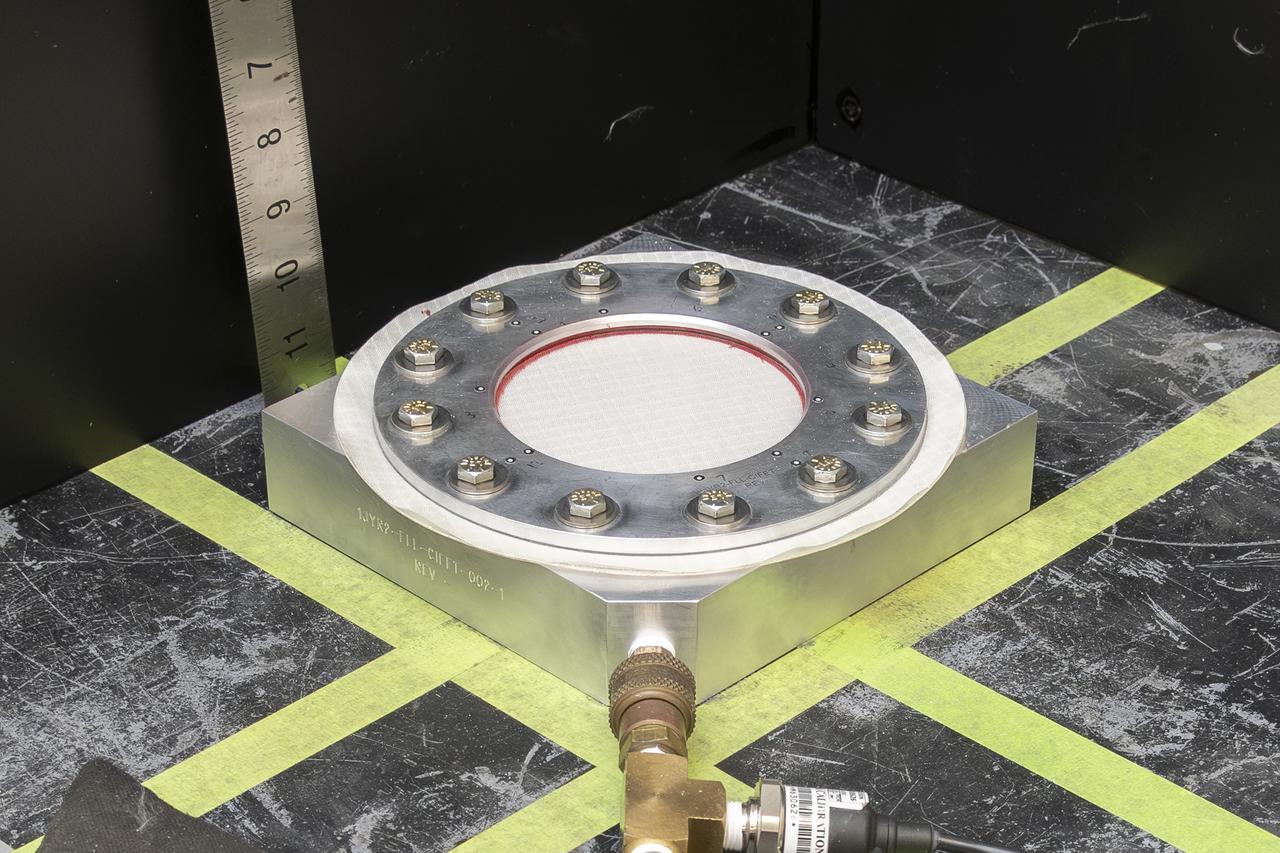
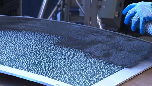
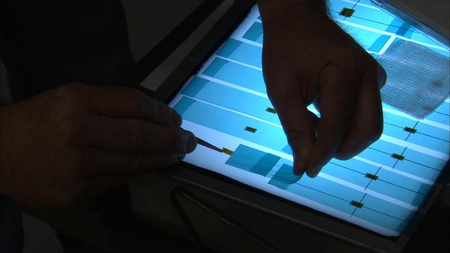
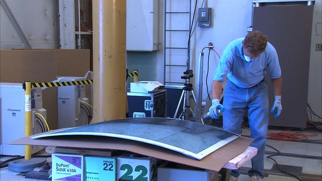
The test team prepares a test fixture with a nylon fabric sample at NASA’s Armstrong Flight Research Center in Edwards, California. The fabric in the test fixture forms a bubble when pressure is applied to the silicone bladder underneath. A similar test can be performed with a sensor on the fabric to verify the sensor will work when stretched in three dimensions.
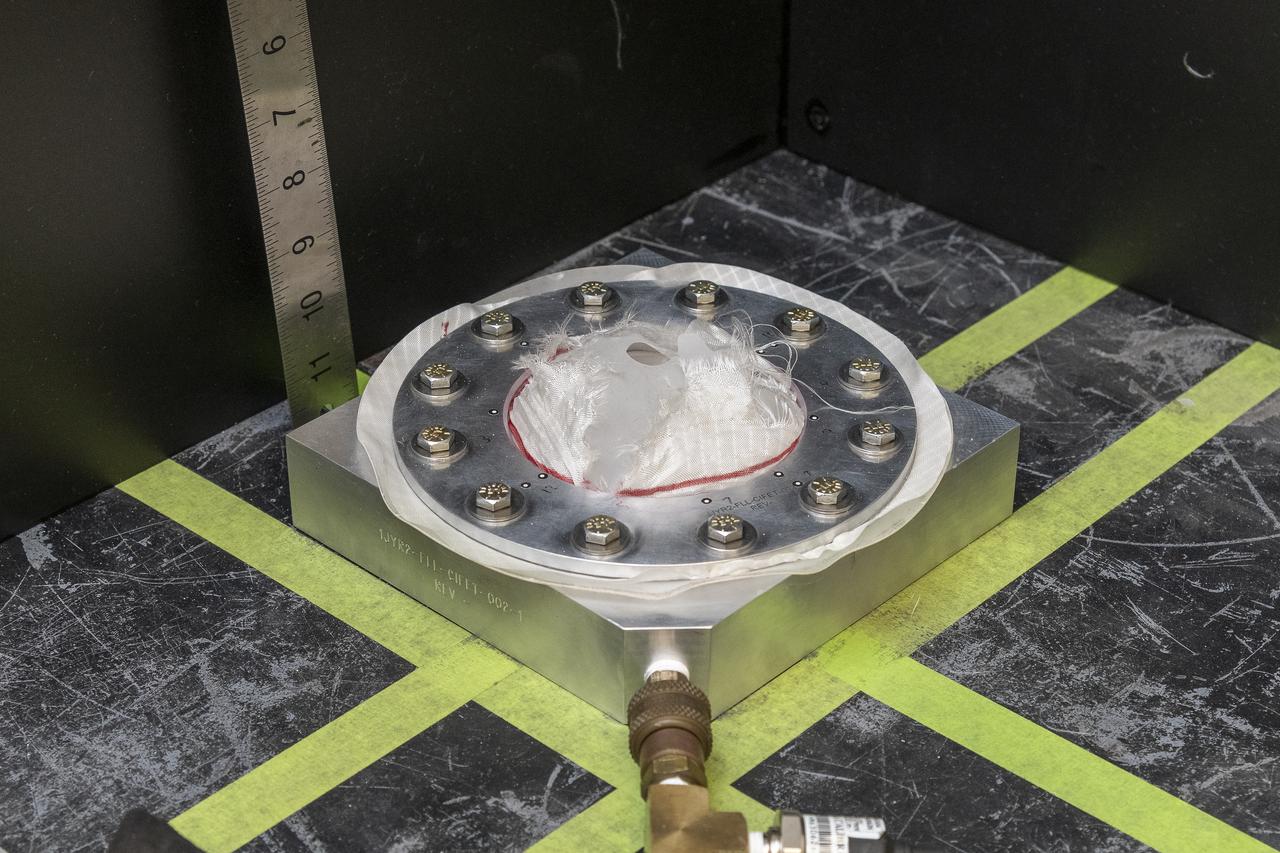
Pressure is applied to a test fixture with a nylon fabric sample until it fails at NASA’s Armstrong Flight Research Center in Edwards, California. The fabric in the test fixture forms a bubble when pressure is applied to the silicone bladder underneath. In this frame, the silicone bladder is visible underneath the torn fabric after it was inflated to failure. A similar test can be performed with a sensor on the fabric to verify the sensor will work when stretched in three dimensions.

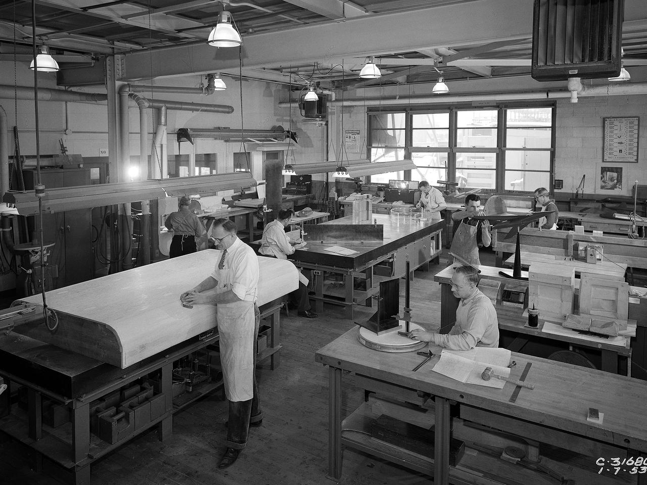
A mechanic and apprentice work on a wooden impeller in the Fabrication Shop at the NACA Lewis Flight Propulsion Laboratory. The 260-person Fabrication Division created almost all of the equipment and models used at the laboratory. The Technical Services Building, referred to as the “Fab Shop”, contained a number of specialized shops in the 1940s and 1950s. These included a Machine Shop, Sheet Metal Shop, Wood and Pattern Shop, Instrument Shop, Thermocouple Shop, Heat Treating Shop, Metallurgical Laboratory, and Fabrication Office. The Machine Shop fabricated research equipment not commercially available. During World War II these technicians produced high-speed cameras for combustion research, impellers and other supercharger components, and key equipment for the lab’s first supersonic wind tunnel. The Wood and Pattern Shop created everything from control panels and cabinets to aircraft model molds for sheet metal work. The Sheet Metal Shop had the ability to work with 0.01 to 4-inches thick steel plates. The Instrument Shop specialized in miniature parts and instrumentation, while the Thermocouple Shop standardized the installation of pitot tubes and thermocouples. The Metallurgical Laboratory contained a control lab for the Heat Treating Shop and a service lab for the NACA Lewis research divisions. The Heat Treating Shop heated metal parts to optimize their physical properties and contained a Precision Castings Foundry to manufacture equipment made of heat resisting alloys.

Northrop Grumman and subcontractor Thales Alenia Space complete fabrication work on the Habitation and Logistics Outpost (HALO) module, one of two of the Gateway Space Station's habitation elements where astronauts will live and work in lunar orbit during deep space Artemis missions.
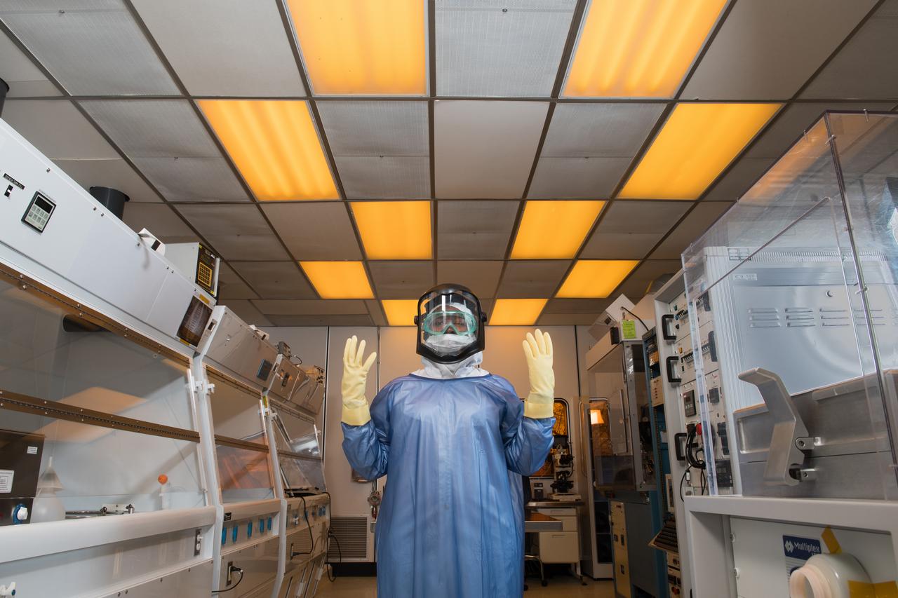
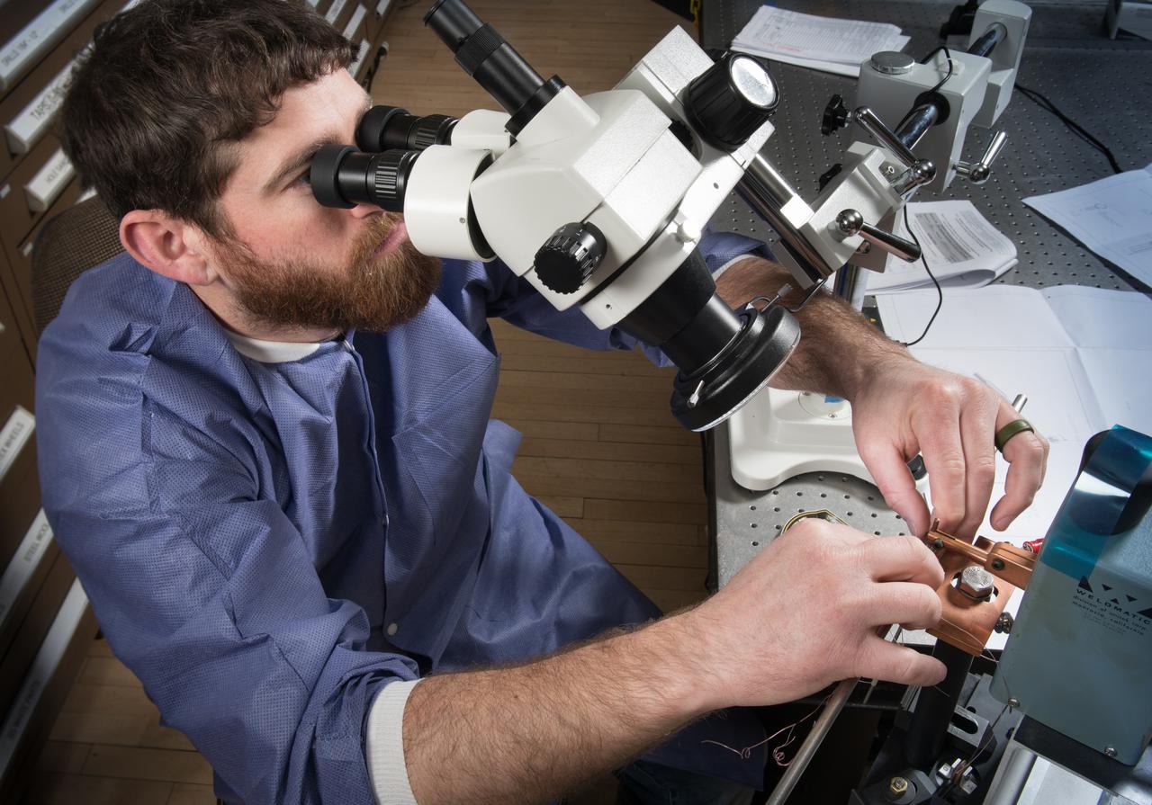
Laboratory Researcher suits up for work in a research clean room. Personal Protective Equipment, PPE, Portait Series
Northrop Grumman and subcontractor Thales Alenia Space complete fabrication work on the Habitation and Logistics Outpost (HALO) module, one of two of the Gateway Space Station's habitation elements where astronauts will live and work in lunar orbit during deep space Artemis missions.
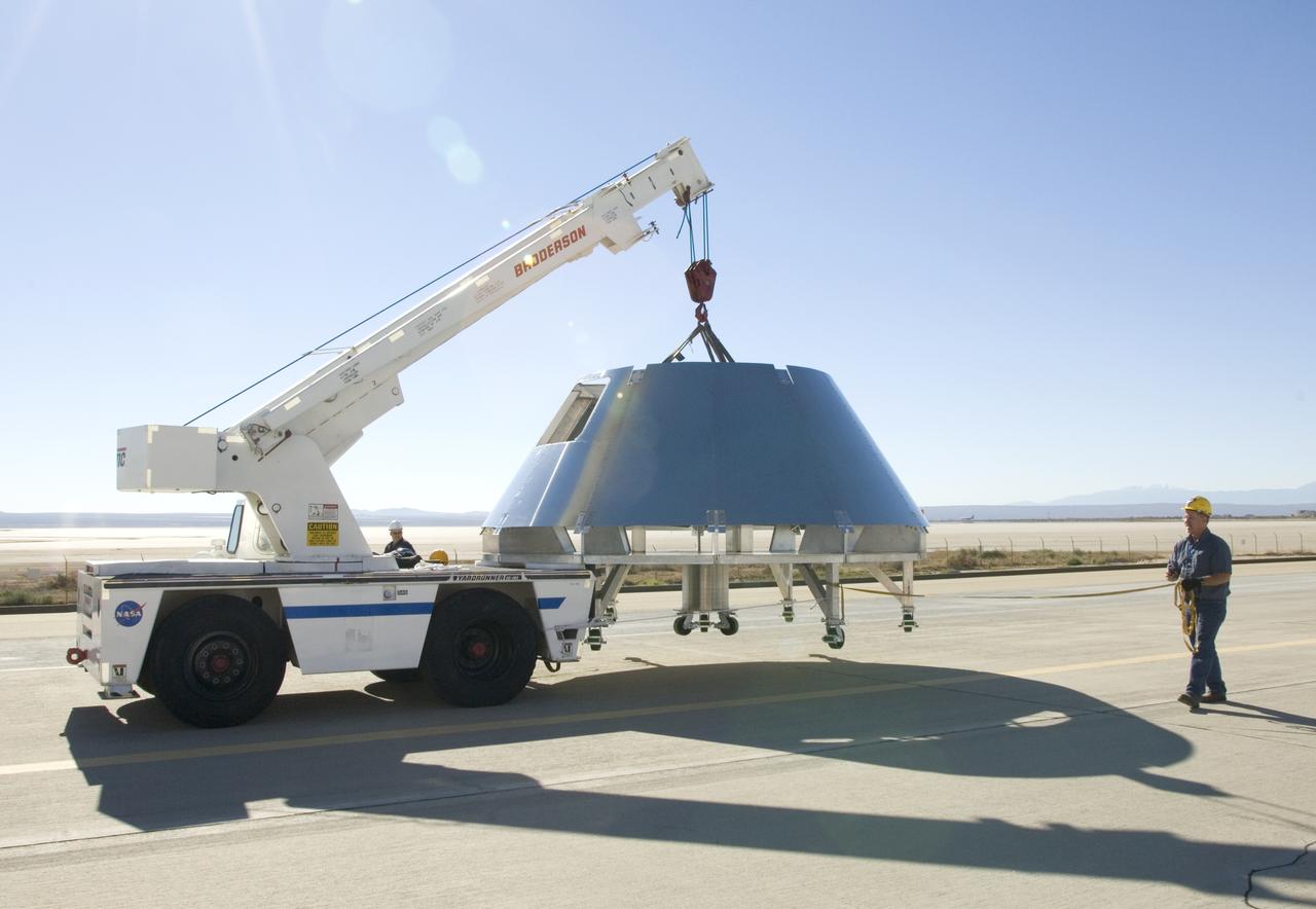
Rogers Dry Lake serves as a backdrop for a mockup Orion crew module built by NASA Dryden Flight Research Center's Fabrication Branch. The module was relocated to Dryden's Shuttle hangar on Sept. 25, 2007.
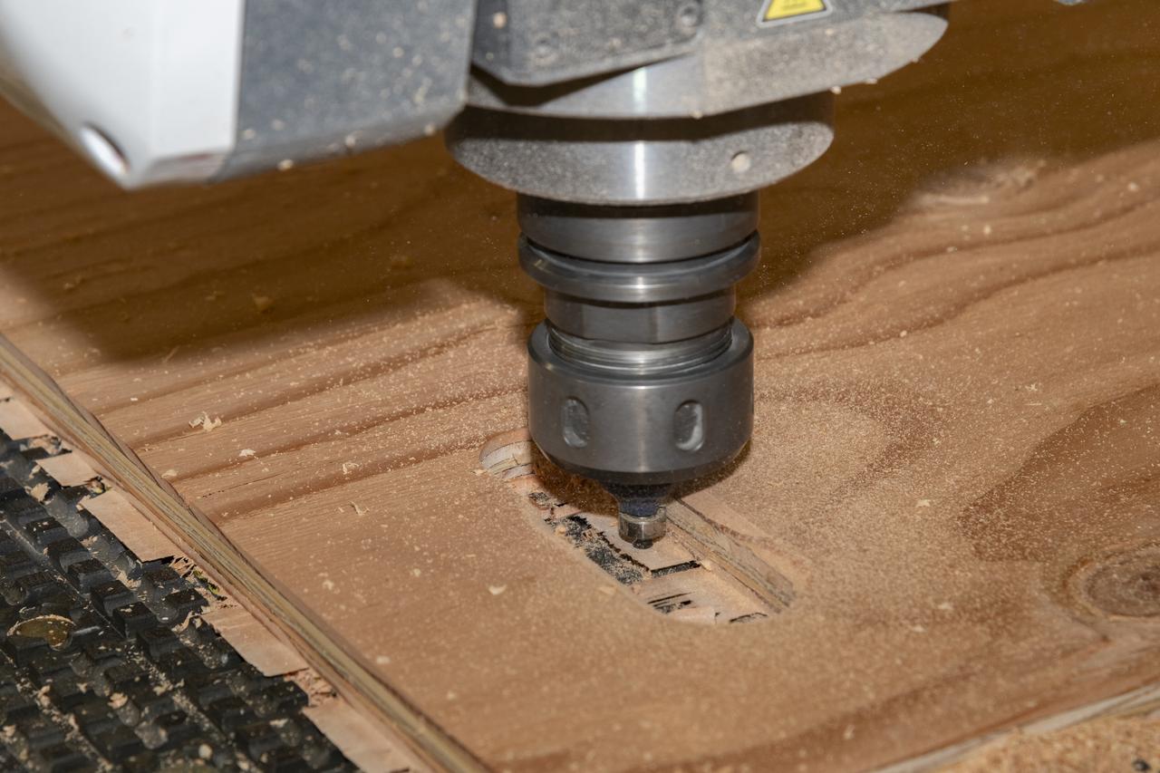
A wood router cuts precise holes in plywood for temporary floorboards on Aug. 26, 2024, in the Experimental Fabrication Shop at NASA’s Armstrong Flight Research Center in Edwards, California. The flooring was designed for the X-66 experimental demonstrator aircraft.
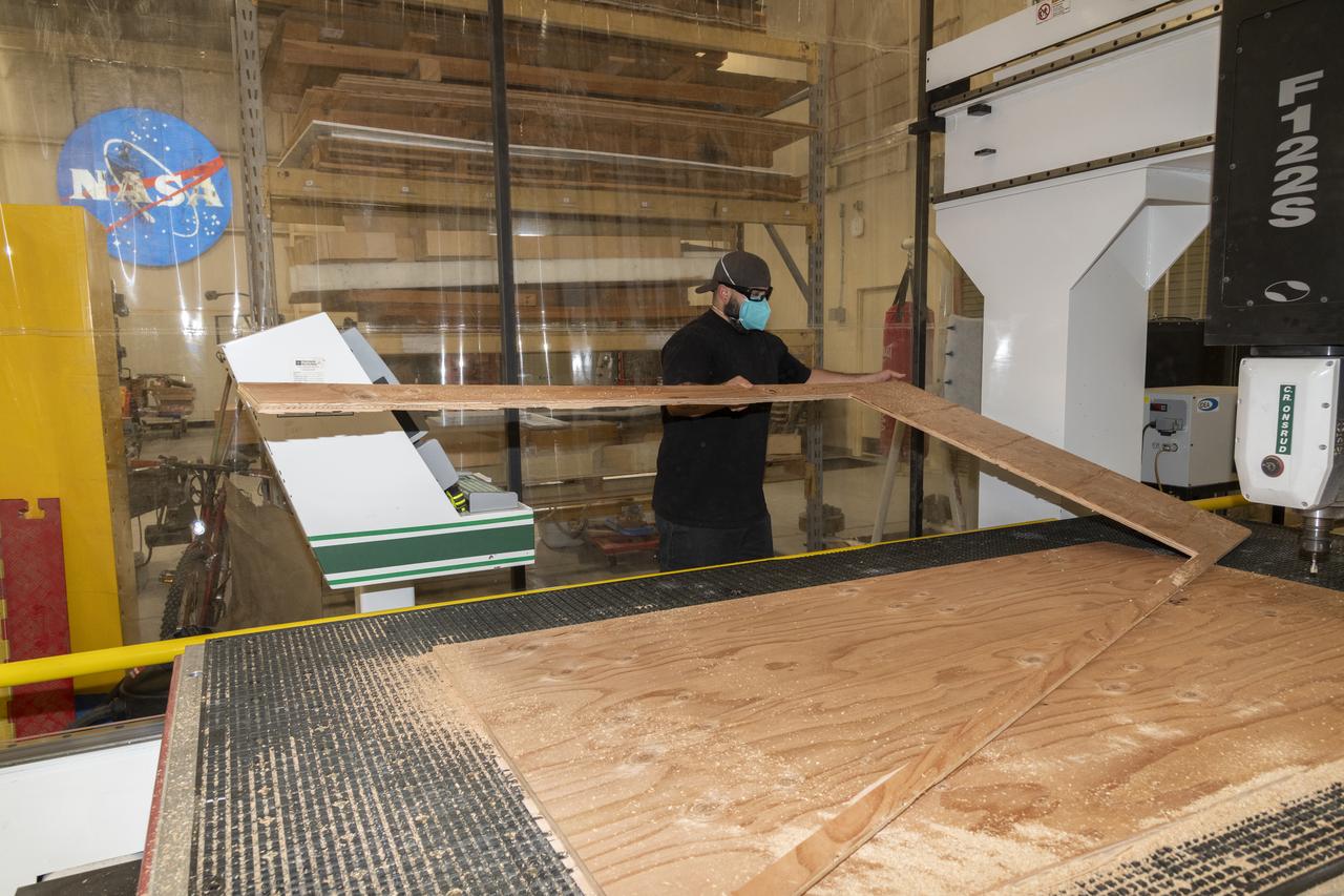
Eric Garza, an engineering technician in the Experimental Fabrication Shop at NASA’s Armstrong Flight Research Center in Edwards, California, cuts plywood to size for temporary floorboards for the X-66 experimental demonstrator aircraft on Aug. 26, 2024.
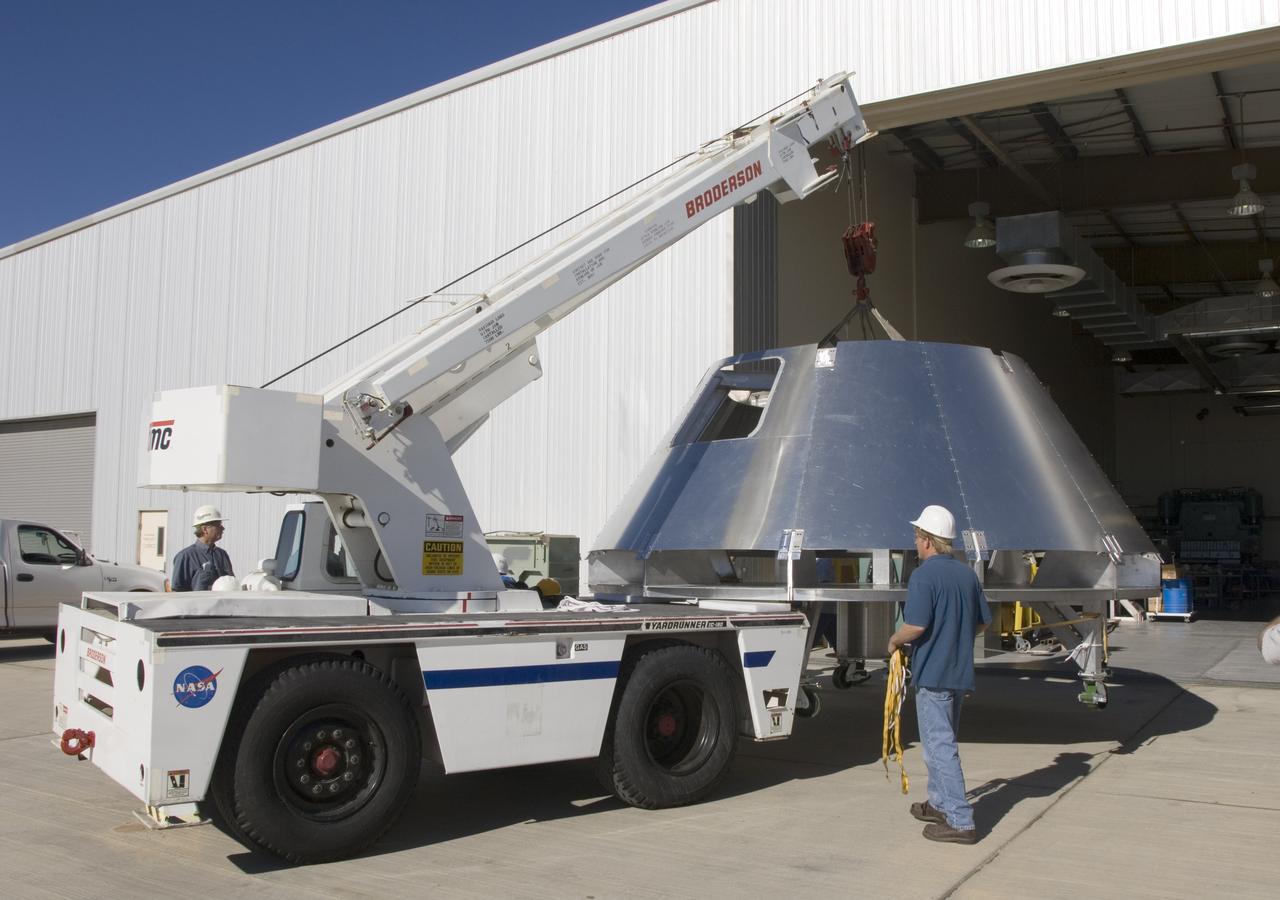
A mockup Orion crew module built by NASA Dryden Flight Research Center's Fabrication Branch gets a lift from its construction site to its new home in Dryden's Shuttle hangar.
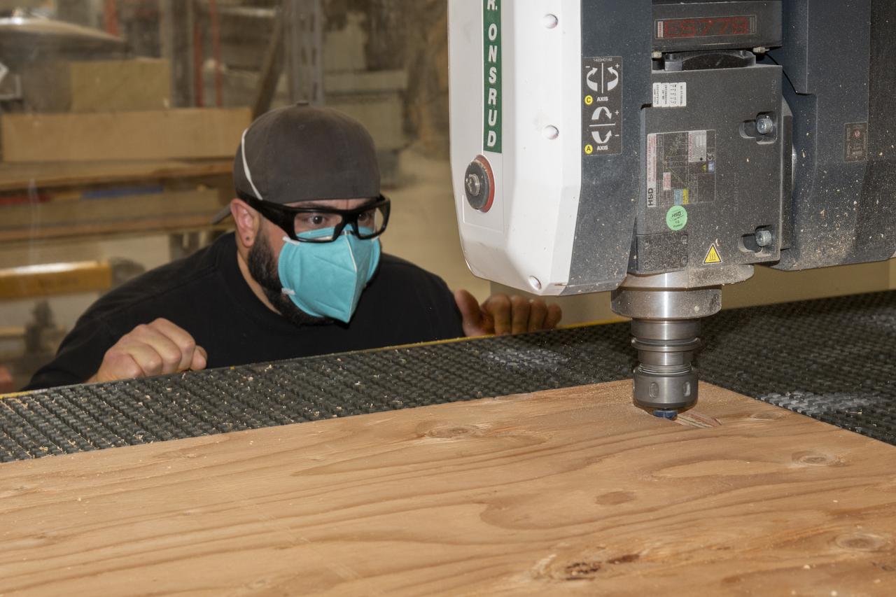
Eric Garza, an engineering technician in the Experimental Fabrication Shop at NASA’s Armstrong Flight Research Center in Edwards, California, observes a wood router cut holes for temporary floorboards on Aug. 26, 2024. The flooring was designed for the X-66 experimental demonstrator aircraft.
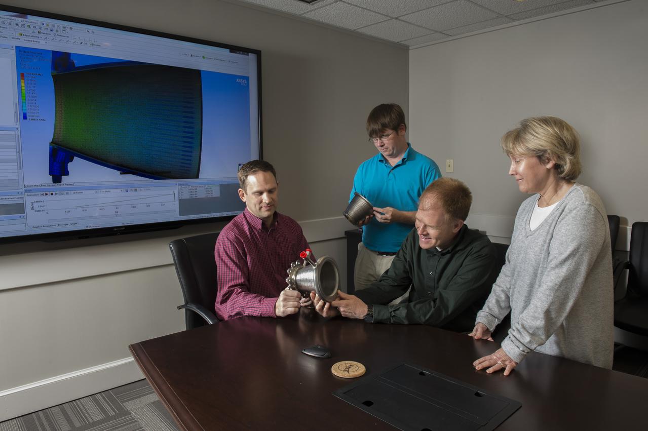
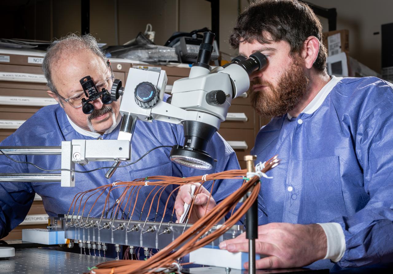
Engineers from NASA Marshall Space Flight Center's Propulsion Department examine nozzles fabricated using a freeform-directed energy wire deposition process. From left are Paul Gradl, Will Brandsmeier, Ian Johnston and Sandy Greene, with the nozzles, which were built using a NASA-patented technology that has the potential to reduce build time from several months to several weeks.
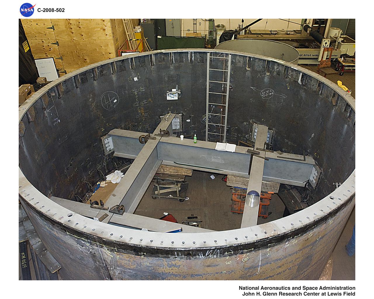
Under the goals of the Vision for Space Exploration, Ares I is a chief component of the cost-effective space transportation infrastructure being developed by NASA's Constellation Program. This transportation system will safely and reliably carry human explorers back to the moon, and then onward to Mars and other destinations in the solar system. The Ares I effort includes multiple project element teams at NASA centers and contract organizations around the nation, and is managed by the Exploration Launch Projects Office at NASA's Marshall Space Flight Center (MFSC). ATK Launch Systems near Brigham City, Utah, is the prime contractor for the first stage booster. ATK's subcontractor, United Space Alliance of Houston, is designing, developing and testing the parachutes at its facilities at NASA's Kennedy Space Center in Florida. NASA's Johnson Space Center in Houston hosts the Constellation Program and Orion Crew Capsule Project Office and provides test instrumentation and support personnel. Together, these teams are developing vehicle hardware, evolving proven technologies, and testing components and systems. Their work builds on powerful, reliable space shuttle propulsion elements and nearly a half-century of NASA space flight experience and technological advances. Ares I is an inline, two-stage rocket configuration topped by the Crew Exploration Vehicle, its service module, and a launch abort system. In this HD video image, processes for upper stage barrel fabrication are talking place. Aluminum panels are manufacturing process demonstration articles that will undergo testing until perfected. The panels are built by AMRO Manufacturing located in El Monte, California. (Largest resolution available)
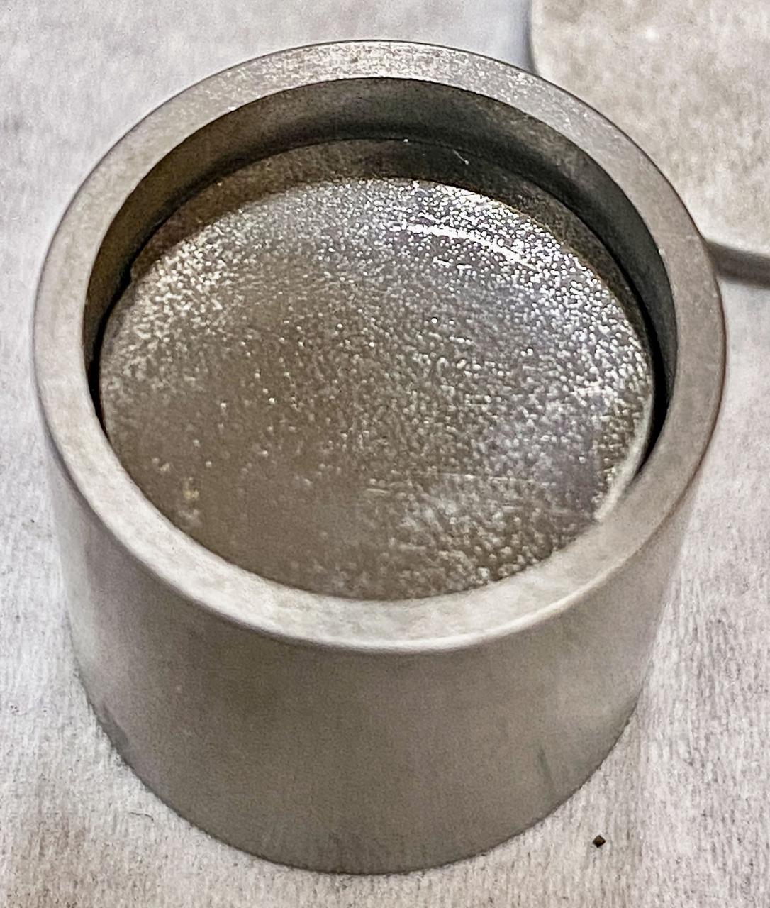
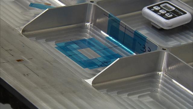
jsc2022e072974 (4/15/2022) --- A preflight sample from the Fabrication of Amorphous Metals in Space (MSL SCA-FAMIS) investigation shows tungsten spheres embedded in a glass-forming alloy loaded into a tungsten crucible. Image courtesy of Douglas Hofmann, NASA JPL/Caltech.
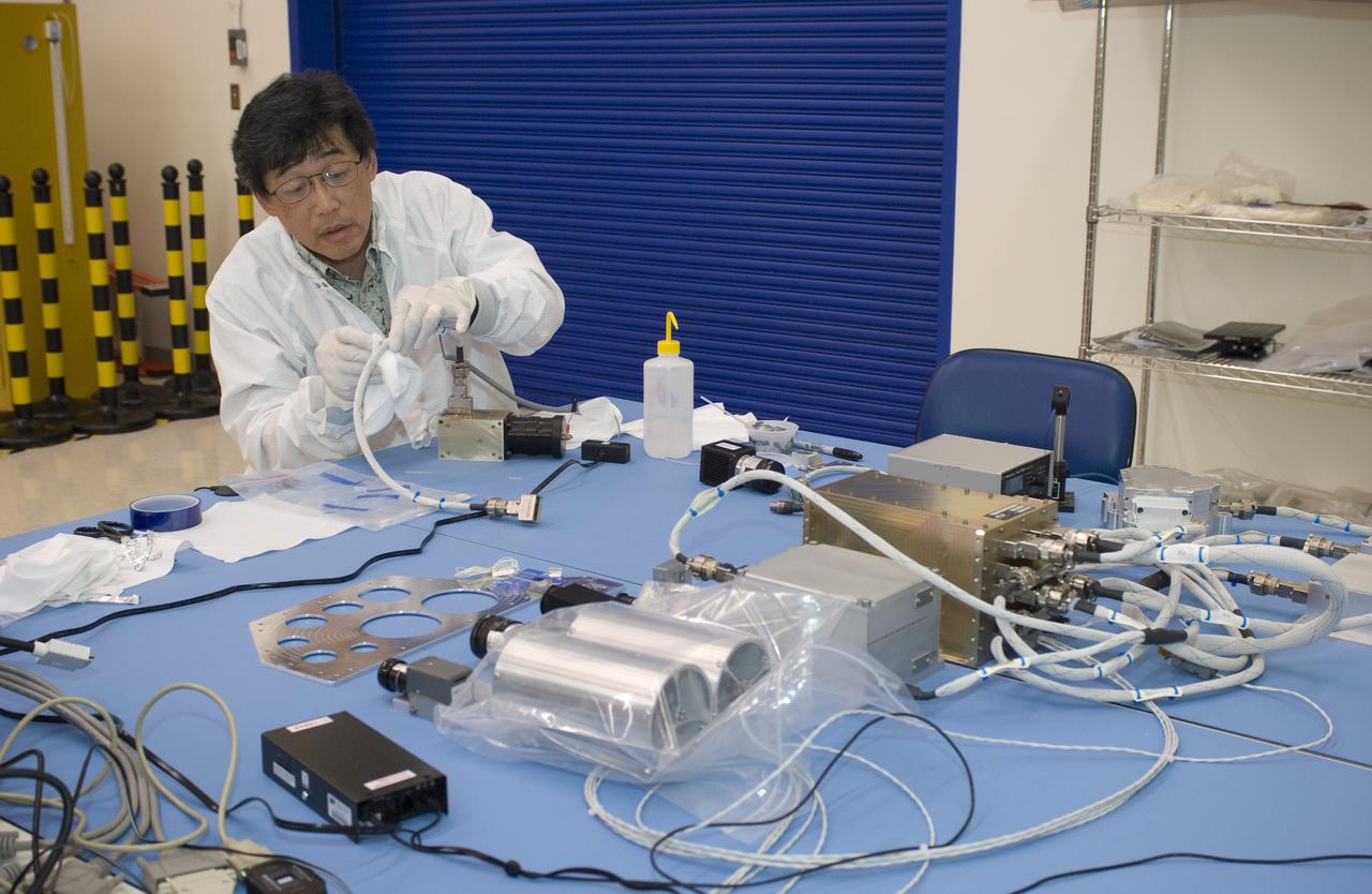
Flow Boiling Condensation Experiment, FBCE Micro Gravity Payload, Condensation Module – Heat Transfer (CM-HT) Test Section Hardware Fabrication
The Exploration Mission-1 (EM-1) left-hand forward skirt for NASA's Space Launch System (SLS) solid rocket boosters arrives inside the high bay at the Booster Fabrication Facility (BFF) at NASA's Kennedy Space Center in Florida. In the BFF, the forward skirt will be inspected and prepared for use on the left-hand solid rocket booster for EM-1. NASA's Orion spacecraft will fly atop the SLS rocket on its first uncrewed flight test.
The Exploration Mission-1 (EM-1) left-hand forward skirt for NASA's Space Launch System (SLS) solid rocket boosters arrives inside the high bay at the Booster Fabrication Facility (BFF) at NASA's Kennedy Space Center in Florida. In the BFF, the forward skirt will be inspected and prepared for use on the left-hand solid rocket booster for EM-1. NASA's Orion spacecraft will fly atop the SLS rocket on its first uncrewed flight test.
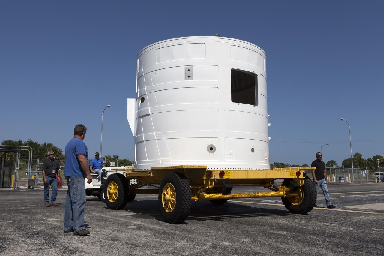
The Exploration Mission-1 (EM-1) left-hand forward skirt for NASA's Space Launch System (SLS) solid rocket boosters arrives at the Booster Fabrication Facility (BFF) at NASA's Kennedy Space Center in Florida from Hangar AE at Cape Canaveral Air Force Station. In the BFF, the forward skirt will be inspected and prepared for use on the left-hand solid rocket booster for EM-1. NASA's Orion spacecraft will fly atop the SLS rocket on its first uncrewed flight test.
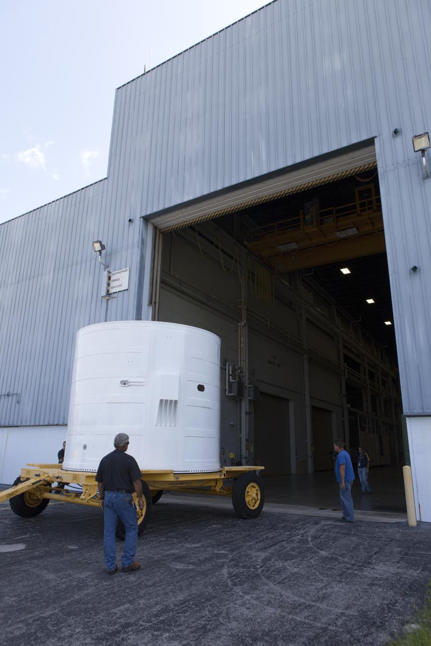
The Exploration Mission-1 (EM-1) left-hand forward skirt for NASA's Space Launch System (SLS) solid rocket boosters arrives at the entrance to the high bay at the Booster Fabrication Facility (BFF) at NASA's Kennedy Space Center in Florida. In the BFF, the forward skirt will be inspected and prepared for use on the left-hand solid rocket booster for EM-1. NASA's Orion spacecraft will fly atop the SLS rocket on its first uncrewed flight test.
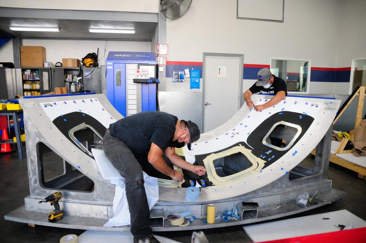
The first element machined for the Artemis III Orion crew module – a cone panel with openings for windows, designed by Orion’s lead contractor, Lockheed Martin, and manufactured by AMRO Fabricating Corp., of South El Monte, California, is shown here on Aug. 14, 2020. The completed panel is on its way to NASA’s Michoud Assembly Facility near New Orleans, Louisiana, where engineers will weld it with other panels as part of Orion’s pressure vessel.
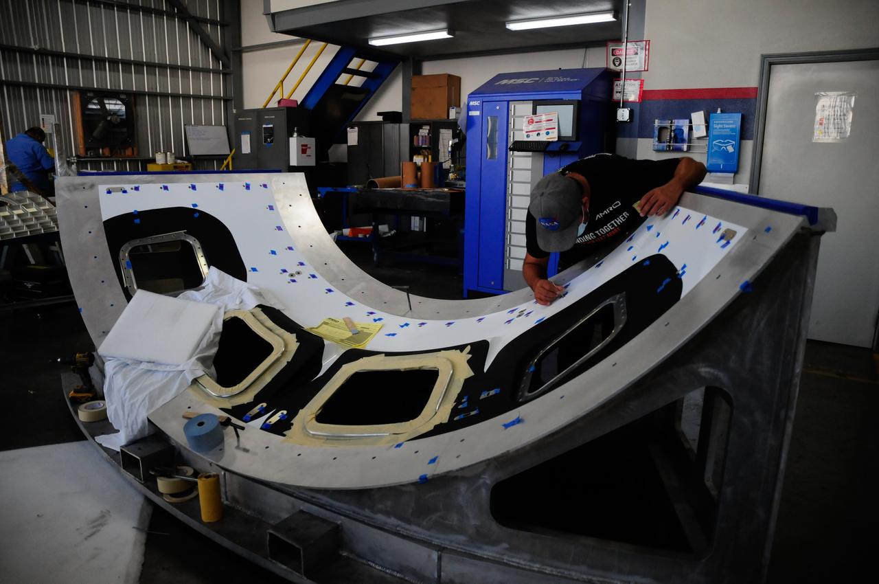
The first element machined for the Artemis III Orion crew module – a cone panel with openings for windows, designed by Orion’s lead contractor, Lockheed Martin, and manufactured by AMRO Fabricating Corp., of South El Monte, California, is shown here on Aug. 14, 2020. The completed panel is on its way to NASA’s Michoud Assembly Facility near New Orleans, Louisiana, where engineers will weld it with other panels as part of Orion’s pressure vessel.
The first element machined for the Artemis III Orion crew module – a cone panel with openings for windows, designed by Orion’s lead contractor, Lockheed Martin, and manufactured by AMRO Fabricating Corp., of South El Monte, California, is shown here on Aug. 14, 2020. The completed panel is on its way to NASA’s Michoud Assembly Facility near New Orleans, Louisiana, where engineers will weld it with other panels as part of Orion’s pressure vessel.

NASA Dryden technicians take measurements inside a fit-check mockup for prior to systems installation on a boilerplate Orion launch abort test crew capsule. A mockup Orion crew module has been constructed by NASA Dryden Flight Research Center's Fabrication Branch. The mockup is being used to develop integration procedures for avionics and instrumentation in advance of the arrival of the first abort flight test article.
A technician in the Instrumentation Shop during the buildup of Flow Boiling Condensation Experiment, FBCE Micro Gravity Payload, Condensation Module – Heat Transfer, CM-HT, Test Section Hardware Fabrication
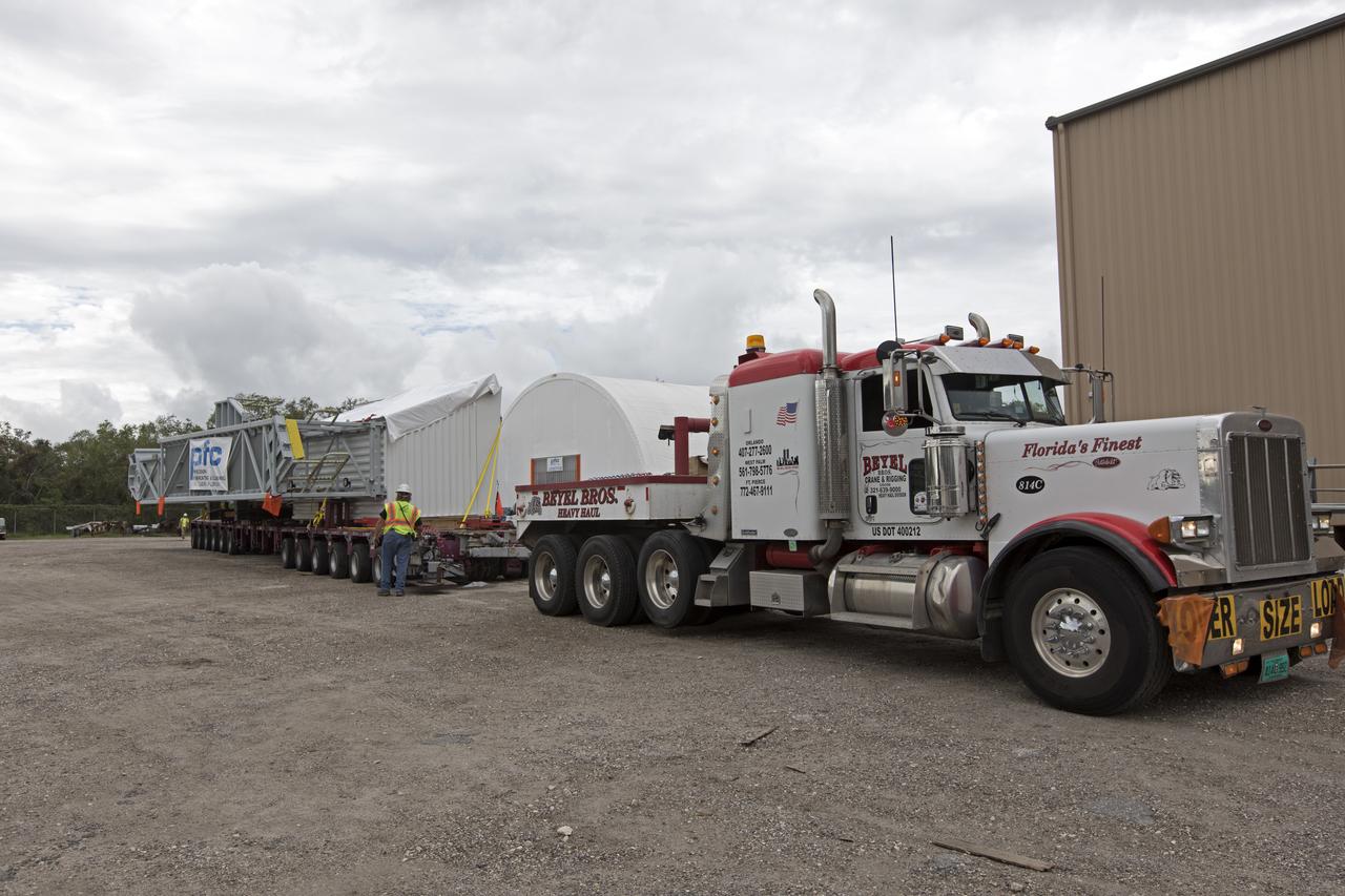
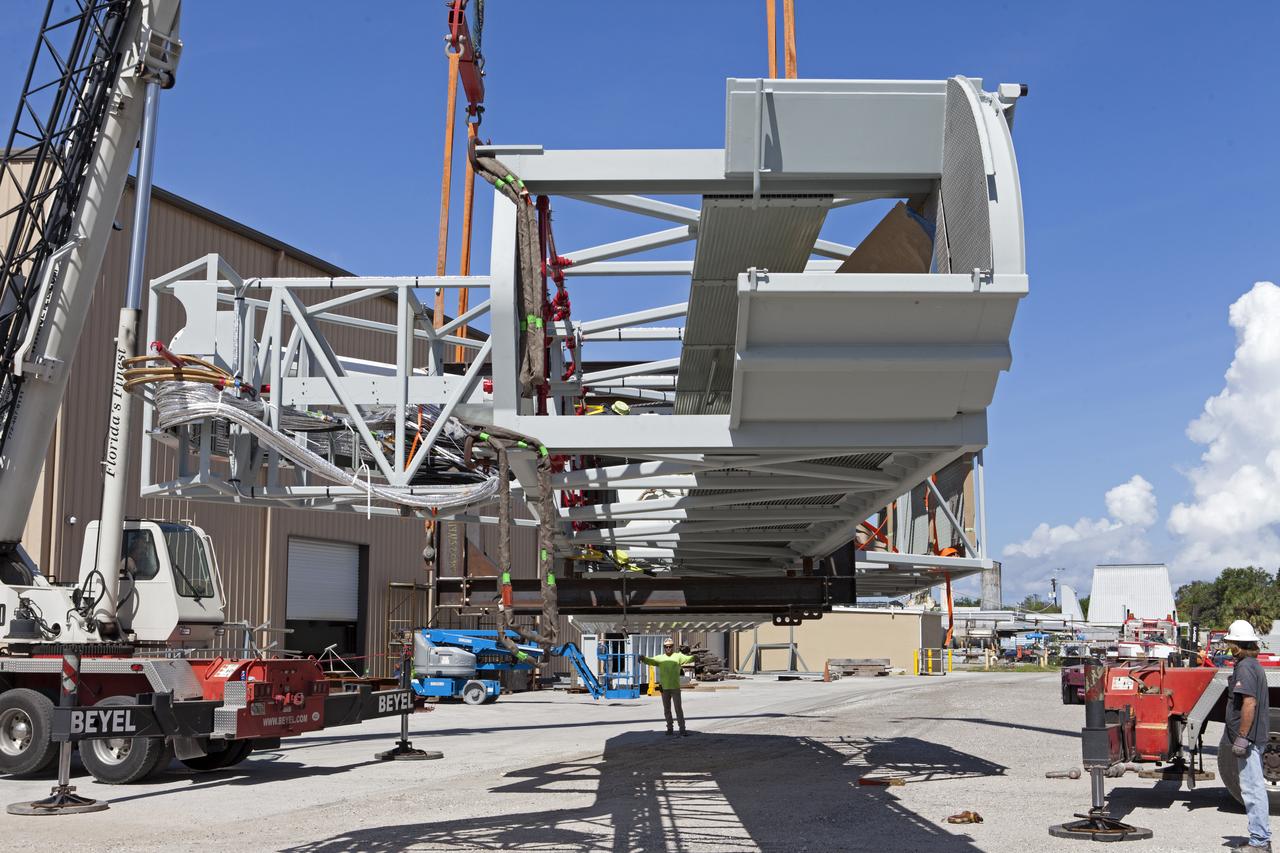
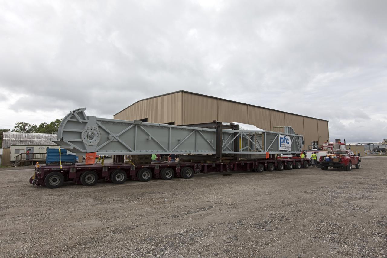
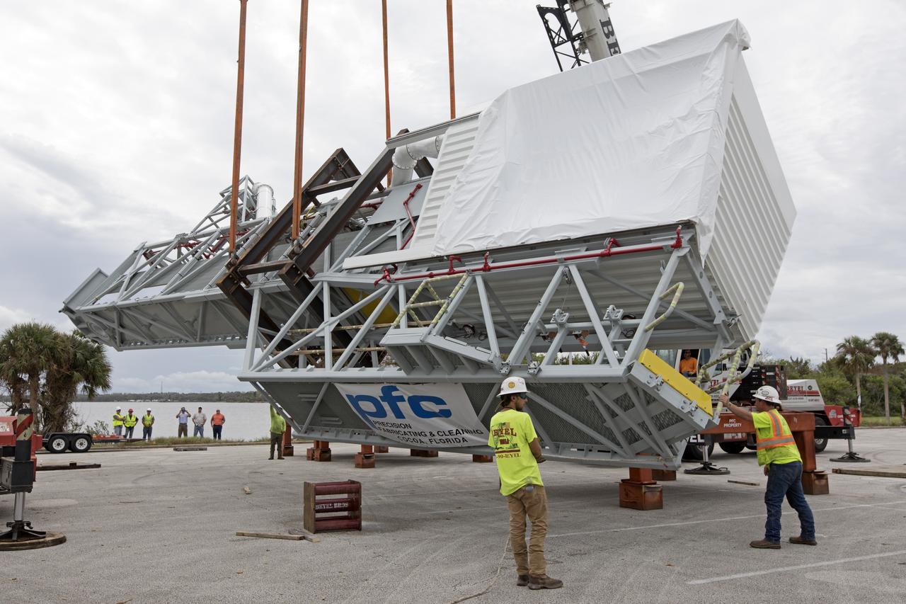
Two heavy-lift cranes are used to lift the Orion crew access arm up from a flatbed truck in a storage location at NASA's Kennedy Space Center in Florida. The access arm was transported from Precision Fabricating and Cleaning in Cocoa, Florida. Later this month, the arm will be transported to the mobile launcher (ML) tower at the center. The crew access arm will be located at about the 274-foot level on the tower. It will rotate from its retracted position and interface with the Orion crew hatch location to provide entry to the Orion crew module. The Ground Systems Development and Operations Program is overseeing installation of umbilicals and launch accessories on the ML tower.
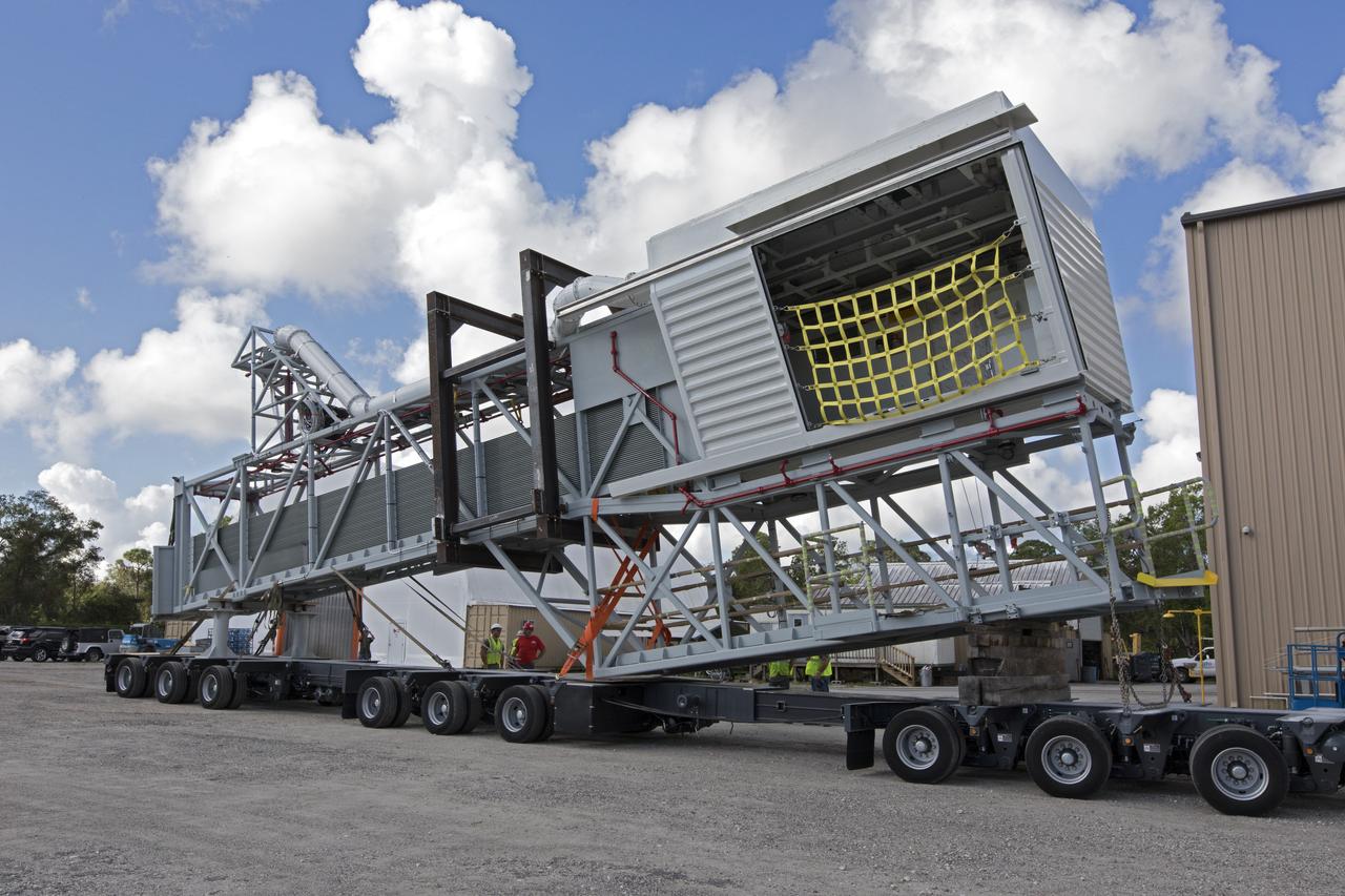
The Orion crew access arm is being secured on a flatbed truck at Precision Fabricating and Cleaning in Cocoa, Florida. The crew access arm will be transported to a storage location near NASA's Kennedy Space Center in Florida. Later this month, the arm will be transported to the mobile launcher (ML) tower at the center. The crew access arm will be located at about the 274-foot level on the tower. It will rotate from its retracted position and interface with the Orion crew hatch location to provide entry to the Orion crew module. The Ground Systems Development and Operations Program is overseeing installation of umbilicals and launch accessories on the ML tower.
The Orion crew access arm is secured on a flatbed truck at Precision Fabricating and Cleaning in Cocoa, Florida and ready to be transported to a storage location at NASA's Kennedy Space Center in Florida. Later this month, the arm will be transported to the mobile launcher (ML) tower at the center. The crew access arm will be located at about the 274-foot level on the tower. It will rotate from its retracted position and interface with the Orion crew hatch location to provide entry to the Orion crew module. The Ground Systems Development and Operations Program is overseeing installation of umbilicals and launch accessories on the ML tower.
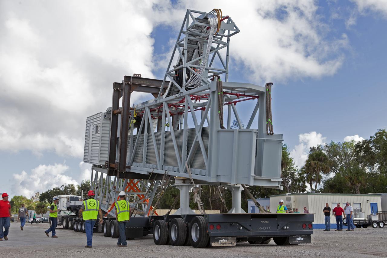
The Orion crew access arm is being secured onto a flatbed truck at Precision Fabricating and Cleaning in Cocoa, Florida. The crew access arm will be transported to a storage location near NASA's Kennedy Space Center in Florida. Later this month, the arm will be transported to the mobile launcher (ML) tower at the center. The crew access arm will be located at about the 274-foot level on the tower. It will rotate from its retracted position and interface with the Orion crew hatch location to provide entry to the Orion crew module. The Ground Systems Development and Operations Program is overseeing installation of umbilicals and launch accessories on the ML tower.
The Orion crew access arm is secured on a flatbed truck at Precision Fabricating and Cleaning in Cocoa, Florida. The crew access arm will be transported to a storage location near NASA's Kennedy Space Center in Florida. Later this month, the arm will be transported to the mobile launcher (ML) tower at the center. The crew access arm will be located at about the 274-foot level on the tower. It will rotate from its retracted position and interface with the Orion crew hatch location to provide entry to the Orion crew module. The Ground Systems Development and Operations Program is overseeing installation of umbilicals and launch accessories on the ML tower.
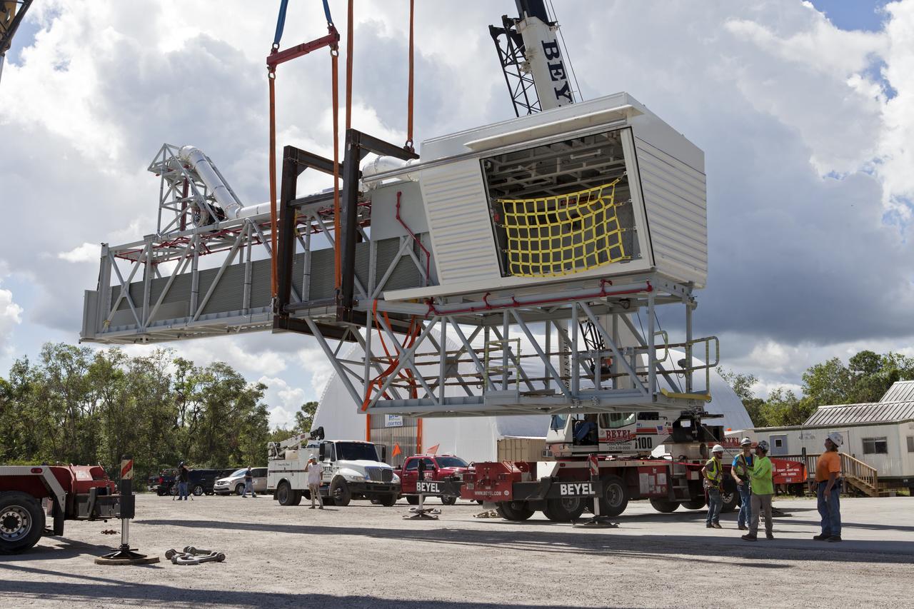
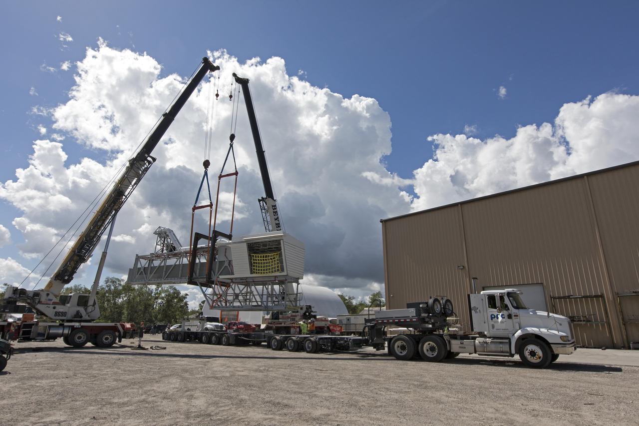
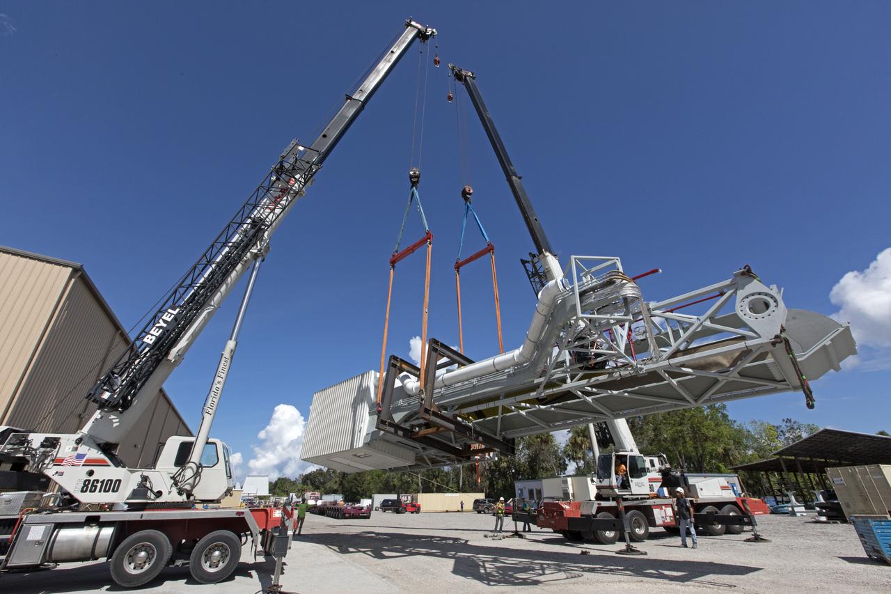
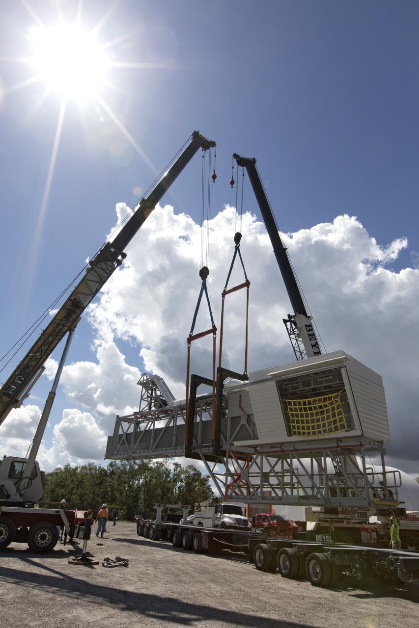
Two heavy-lift cranes are being used to move the Orion crew access arm and lower it onto a flatbed truck at Precision Fabricating and Cleaning in Cocoa, Florida. The crew access arm will be transported to a storage location near NASA's Kennedy Space Center in Florida. Later this month, the arm will be transported to the mobile launcher (ML) tower at the center. The crew access arm will be located at about the 274-foot level on the tower. It will rotate from its retracted position and interface with the Orion crew hatch location to provide entry to the Orion crew module. The Ground Systems Development and Operations Program is overseeing installation of umbilicals and launch accessories on the ML tower.
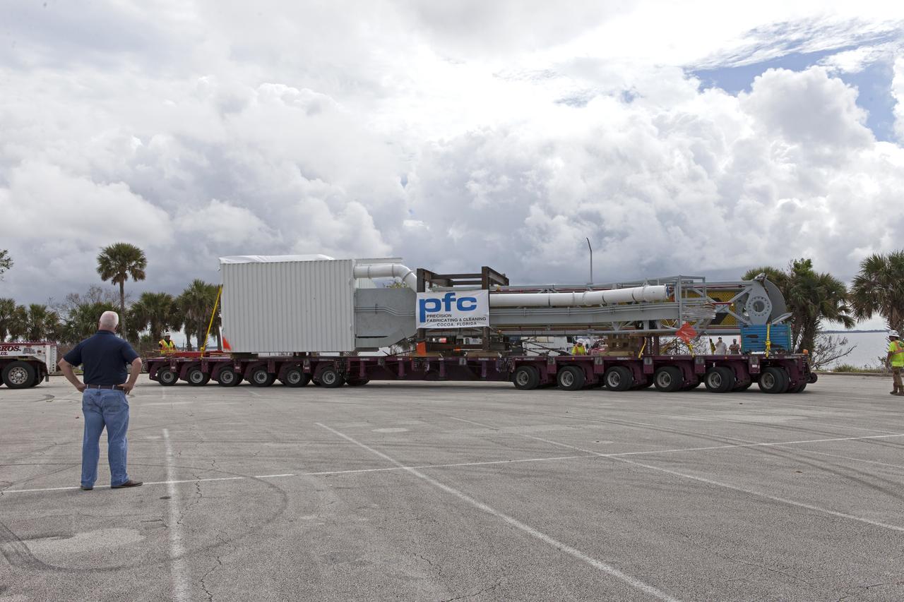
The Orion crew access arm departs Precision Fabricating and Cleaning in Cocoa, Florida, atop a flatbed truck. The access arm will be transported to a storage location at NASA's Kennedy Space Center in Florida. Later this month, the arm will be transported to the mobile launcher (ML) tower at the center. The crew access arm will be located at about the 274-foot level on the tower. It will rotate from its retracted position and interface with the Orion crew hatch location to provide entry to the Orion crew module. The Ground Systems Development and Operations Program is overseeing installation of umbilicals and launch accessories on the ML tower.
The Orion crew access arm is being moved by crane onto a flatbed truck at Precision Fabricating and Cleaning in Cocoa, Florida. The crew access arm will be transported to a storage location near NASA's Kennedy Space Center in Florida. Later this month, the arm will be transported to the mobile launcher (ML) tower at the center. The crew access arm will be located at about the 274-foot level on the tower. It will rotate from its retracted position and interface with the Orion crew hatch location to provide entry to the Orion crew module. The Ground Systems Development and Operations Program is overseeing installation of umbilicals and launch accessories on the ML tower.
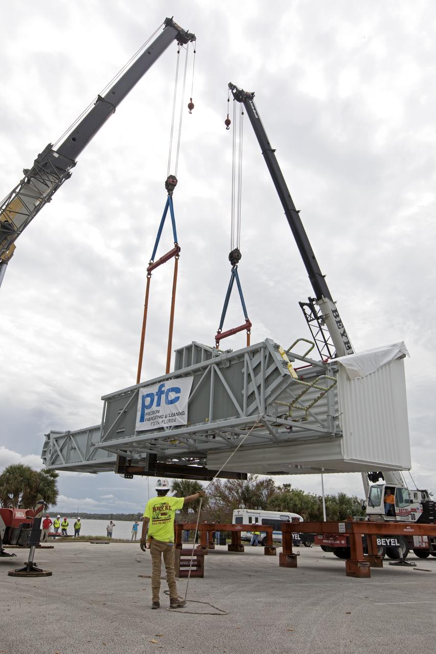
Two heavy-lift cranes are being used to lower the Orion crew access arm onto a flatbed truck at Precision Fabricating and Cleaning in Cocoa, Florida. The crew access arm will be transported to a storage location near NASA's Kennedy Space Center in Florida. Later this month, the arm will be transported to the mobile launcher (ML) tower at the center. The crew access arm will be located at about the 274-foot level on the tower. It will rotate from its retracted position and interface with the Orion crew hatch location to provide entry to the Orion crew module. The Ground Systems Development and Operations Program is overseeing installation of umbilicals and launch accessories on the ML tower.
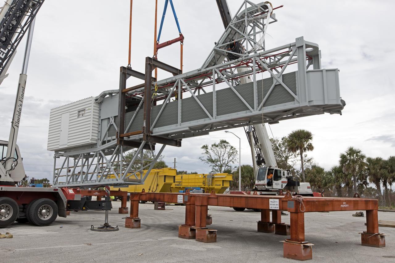
Two heavy-lift cranes are used to lower the Orion crew access arm onto a work stand in a storage location at NASA's Kennedy Space Center in Florida. The access arm was transported from Precision Fabricating and Cleaning in Cocoa, Florida. Later this month, the arm will be transported to the mobile launcher (ML) tower at the center. The crew access arm will be located at about the 274-foot level on the tower. It will rotate from its retracted position and interface with the Orion crew hatch location to provide entry to the Orion crew module. The Ground Systems Development and Operations Program is overseeing installation of umbilicals and launch accessories on the ML tower.

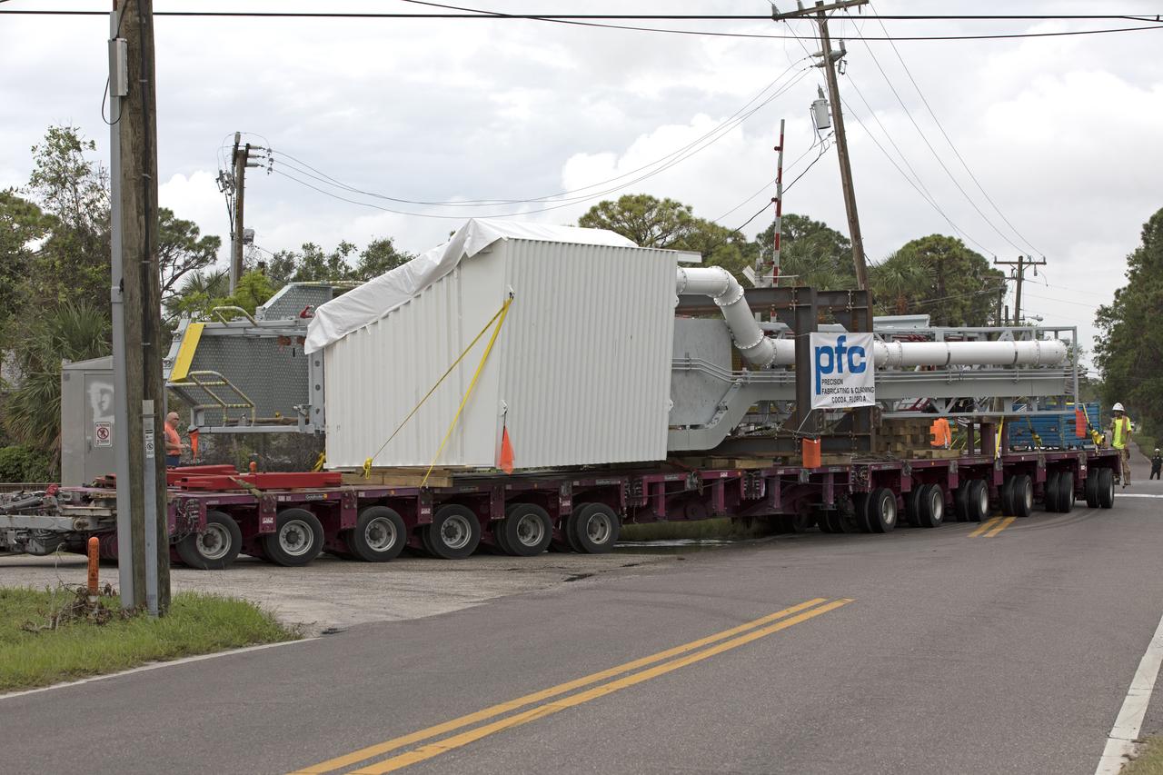
A flatbed truck with the Orion crew access arm secured atop travels along a road in Cocoa, Florida, after departing Precision Fabricating and Cleaning. The access arm will be transported to a storage location at NASA's Kennedy Space Center in Florida. Later this month, the arm will be transported to the mobile launcher (ML) tower at the center. The crew access arm will be located at about the 274-foot level on the tower. It will rotate from its retracted position and interface with the Orion crew hatch location to provide entry to the Orion crew module. The Ground Systems Development and Operations Program is overseeing installation of umbilicals and launch accessories on the ML tower.

Two heavy-lift cranes lower the Orion crew access arm onto a work stand in a storage location at NASA's Kennedy Space Center in Florida. The access arm was transported from Precision Fabricating and Cleaning in Cocoa, Florida. Later this month, the arm will be transported to the mobile launcher (ML) tower at the center. The crew access arm will be located at about the 274-foot level on the tower. It will rotate from its retracted position and interface with the Orion crew hatch location to provide entry to the Orion crew module. The Ground Systems Development and Operations Program is overseeing installation of umbilicals and launch accessories on the ML tower.
The Orion crew access arm is secured on a flatbed truck at Precision Fabricating and Cleaning in Cocoa, Florida and ready to be transported to a storage location at NASA's Kennedy Space Center in Florida. Later this month, the arm will be transported to the mobile launcher (ML) tower at the center. The crew access arm will be located at about the 274-foot level on the tower. It will rotate from its retracted position and interface with the Orion crew hatch location to provide entry to the Orion crew module. The Ground Systems Development and Operations Program is overseeing installation of umbilicals and launch accessories on the ML tower.
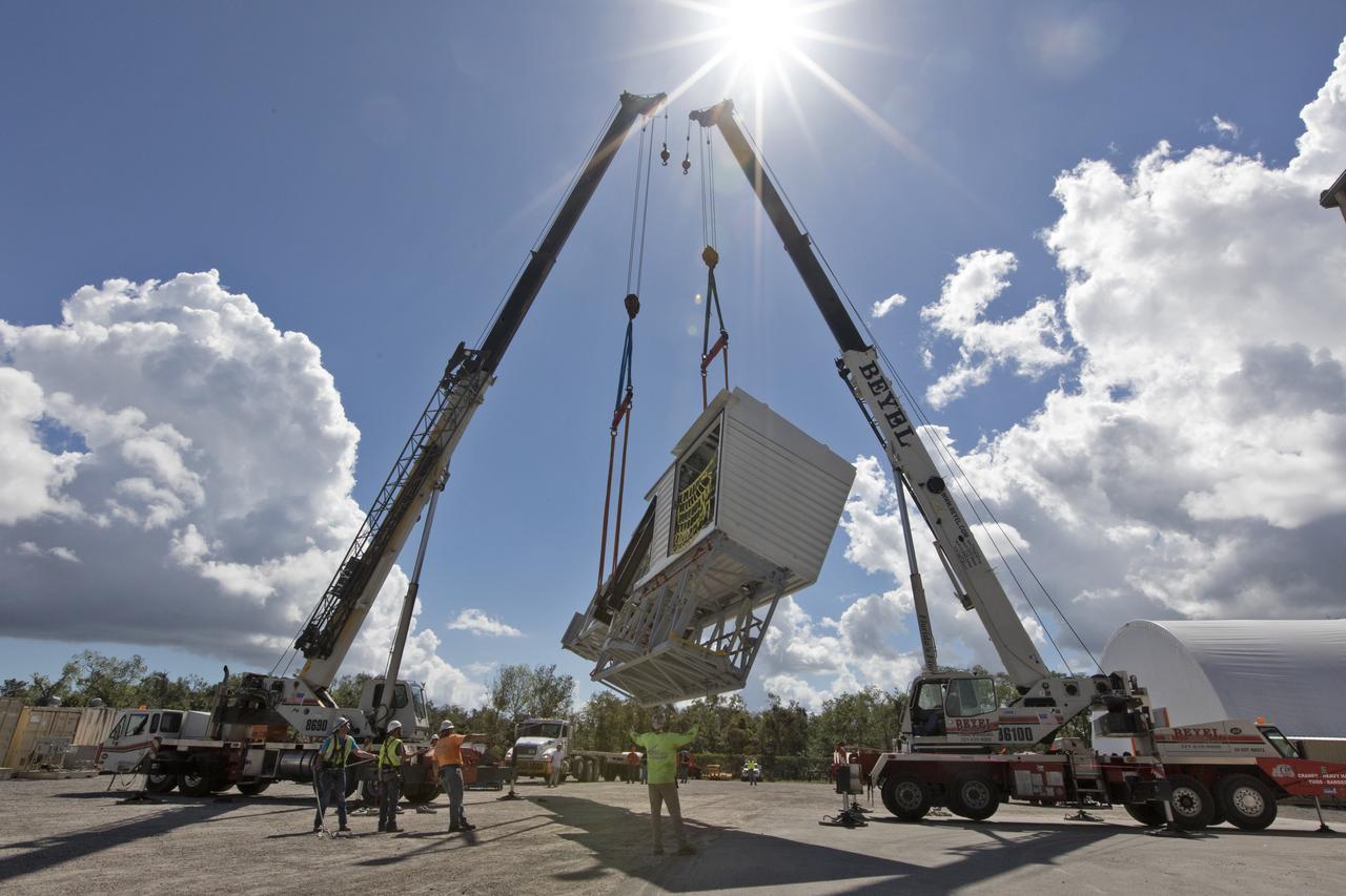
Two heavy-lift cranes are being used to move the Orion crew access arm and lower it onto a flatbed truck at Precision Fabricating and Cleaning in Cocoa, Florida. The crew access arm will be transported to a storage location near NASA's Kennedy Space Center in Florida. Later this month, the arm will be transported to the mobile launcher (ML) tower at the center. The crew access arm will be located at about the 274-foot level on the tower. It will rotate from its retracted position and interface with the Orion crew hatch location to provide entry to the Orion crew module. The Ground Systems Development and Operations Program is overseeing installation of umbilicals and launch accessories on the ML tower.
Two heavy-lift cranes are being used to move the Orion crew access arm and lower it onto a flatbed truck at Precision Fabricating and Cleaning in Cocoa, Florida. The crew access arm will be transported to a storage location near NASA's Kennedy Space Center in Florida. Later this month, the arm will be transported to the mobile launcher (ML) tower at the center. The crew access arm will be located at about the 274-foot level on the tower. It will rotate from its retracted position and interface with the Orion crew hatch location to provide entry to the Orion crew module. The Ground Systems Development and Operations Program is overseeing installation of umbilicals and launch accessories on the ML tower.
Two heavy-lift cranes are used to lower the Orion crew access arm onto a flatbed truck at Precision Fabricating and Cleaning in Cocoa, Florida. The crew access arm will be transported to a storage location near NASA's Kennedy Space Center in Florida. Later this month, the arm will be transported to the mobile launcher (ML) tower at the center. The crew access arm will be located at about the 274-foot level on the tower. It will rotate from its retracted position and interface with the Orion crew hatch location to provide entry to the Orion crew module. The Ground Systems Development and Operations Program is overseeing installation of umbilicals and launch accessories on the ML tower.
Two heavy-lift cranes are used to tilt and lower the Orion crew access arm onto a work stand in a storage location at NASA's Kennedy Space Center in Florida. The access arm was transported from Precision Fabricating and Cleaning in Cocoa, Florida. Later this month, the arm will be transported to the mobile launcher (ML) tower at the center. The crew access arm will be located at about the 274-foot level on the tower. It will rotate from its retracted position and interface with the Orion crew hatch location to provide entry to the Orion crew module. The Ground Systems Development and Operations Program is overseeing installation of umbilicals and launch accessories on the ML tower.
A flatbed truck with the Orion crew access arm secured atop arrives in a storage location at NASA's Kennedy Space Center in Florida. The access arm was transported from Precision Fabricating and Cleaning in Cocoa, Florida. Later this month, the arm will be transported to the mobile launcher (ML) tower at the center. The crew access arm will be located at about the 274-foot level on the tower. It will rotate from its retracted position and interface with the Orion crew hatch location to provide entry to the Orion crew module. The Ground Systems Development and Operations Program is overseeing installation of umbilicals and launch accessories on the ML tower.
Two heavy-lift cranes are used to lower the Orion crew access arm onto a work stand in a storage location at NASA's Kennedy Space Center in Florida. The access arm was transported from Precision Fabricating and Cleaning in Cocoa, Florida. Later this month, the arm will be transported to the mobile launcher (ML) tower at the center. The crew access arm will be located at about the 274-foot level on the tower. It will rotate from its retracted position and interface with the Orion crew hatch location to provide entry to the Orion crew module. The Ground Systems Development and Operations Program is overseeing installation of umbilicals and launch accessories on the ML tower.
Under the goals of the Vision for Space Exploration, Ares I is a chief component of the cost-effective space transportation infrastructure being developed by NASA's Constellation Program. This transportation system will safely and reliably carry human explorers back to the moon, and then onward to Mars and other destinations in the solar system. The Ares I effort includes multiple project element teams at NASA centers and contract organizations around the nation, and is managed by the Exploration Launch Projects Office at NASA's Marshall Space Flight Center (MFSC). ATK Launch Systems near Brigham City, Utah, is the prime contractor for the first stage booster. ATK's subcontractor, United Space Alliance of Houston, is designing, developing and testing the parachutes at its facilities at NASA's Kennedy Space Center in Florida. NASA's Johnson Space Center in Houston hosts the Constellation Program and Orion Crew Capsule Project Office and provides test instrumentation and support personnel. Together, these teams are developing vehicle hardware, evolving proven technologies, and testing components and systems. Their work builds on powerful, reliable space shuttle propulsion elements and nearly a half-century of NASA space flight experience and technological advances. Ares I is an inline, two-stage rocket configuration topped by the Crew Exploration Vehicle, its service module, and a launch abort system. This HD video image depicts a manufactured aluminum panel, that will fabricate the Ares I upper stage barrel, undergoing a confidence panel test. In this test, the bent aluminum is stressed to breaking point and thoroughly examined. The panels are manufactured by AMRO Manufacturing located in El Monte, California. (Highest resolution available)
Under the goals of the Vision for Space Exploration, Ares I is a chief component of the cost-effective space transportation infrastructure being developed by NASA's Constellation Program. This transportation system will safely and reliably carry human explorers back to the moon, and then onward to Mars and other destinations in the solar system. The Ares I effort includes multiple project element teams at NASA centers and contract organizations around the nation, and is managed by the Exploration Launch Projects Office at NASA's Marshall Space Flight Center (MFSC). ATK Launch Systems near Brigham City, Utah, is the prime contractor for the first stage booster. ATK's subcontractor, United Space Alliance of Houston, is designing, developing and testing the parachutes at its facilities at NASA's Kennedy Space Center in Florida. NASA's Johnson Space Center in Houston hosts the Constellation Program and Orion Crew Capsule Project Office and provides test instrumentation and support personnel. Together, these teams are developing vehicle hardware, evolving proven technologies, and testing components and systems. Their work builds on powerful, reliable space shuttle propulsion elements and nearly a half-century of NASA space flight experience and technological advances. Ares I is an inline, two-stage rocket configuration topped by the Crew Exploration Vehicle, its service module, and a launch abort system. This HD video image depicts a manufactured panel that will be used for the Ares I upper stage barrel fabrication. The aluminum panels are manufacturing process demonstration articles that will undergo testing until perfected. The panels are built by AMRO Manufacturing located in El Monte, California. (Highest resolution available)
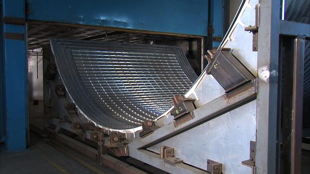
Under the goals of the Vision for Space Exploration, Ares I is a chief component of the cost-effective space transportation infrastructure being developed by NASA's Constellation Program. This transportation system will safely and reliably carry human explorers back to the moon, and then onward to Mars and other destinations in the solar system. The Ares I effort includes multiple project element teams at NASA centers and contract organizations around the nation, and is managed by the Exploration Launch Projects Office at NASA's Marshall Space Flight Center (MFSC). ATK Launch Systems near Brigham City, Utah, is the prime contractor for the first stage booster. ATK's subcontractor, United Space Alliance of Houston, is designing, developing and testing the parachutes at its facilities at NASA's Kennedy Space Center in Florida. NASA's Johnson Space Center in Houston hosts the Constellation Program and Orion Crew Capsule Project Office and provides test instrumentation and support personnel. Together, these teams are developing vehicle hardware, evolving proven technologies, and testing components and systems. Their work builds on powerful, reliable space shuttle propulsion elements and nearly a half-century of NASA space flight experience and technological advances. Ares I is an inline, two-stage rocket configuration topped by the Crew Exploration Vehicle, its service module, and a launch abort system. This HD video image depicts a manufactured aluminum panel that will be used to fabricate the Ares I upper stage barrel, undergoing a confidence panel test. In this test, the bent aluminum is stressed to breaking point and thoroughly examined. The panels are manufactured by AMRO Manufacturing located in El Monte, California. (Highest resolution available)

Under the goals of the Vision for Space Exploration, Ares I is a chief component of the cost-effective space transportation infrastructure being developed by NASA's Constellation Program. This transportation system will safely and reliably carry human explorers back to the moon, and then onward to Mars and other destinations in the solar system. The Ares I effort includes multiple project element teams at NASA centers and contract organizations around the nation, and is managed by the Exploration Launch Projects Office at NASA's Marshall Space Flight Center (MFSC). ATK Launch Systems near Brigham City, Utah, is the prime contractor for the first stage booster. ATK's subcontractor, United Space Alliance of Houston, is designing, developing and testing the parachutes at its facilities at NASA's Kennedy Space Center in Florida. NASA's Johnson Space Center in Houston hosts the Constellation Program and Orion Crew Capsule Project Office and provides test instrumentation and support personnel. Together, these teams are developing vehicle hardware, evolving proven technologies, and testing components and systems. Their work builds on powerful, reliable space shuttle propulsion elements and nearly a half-century of NASA space flight experience and technological advances. Ares I is an inline, two-stage rocket configuration topped by the Crew Exploration Vehicle, its service module, and a launch abort system. This HD video image, depicts a manufactured aluminum panel, that will be used to fabricate the Ares I upper stage barrel, undergoing a confidence panel test. In this test, the bent aluminum is stressed to breaking point and thoroughly examined. The panels are manufactured by AMRO Manufacturing located in El Monte, California. (Highest resolution available)
Under the goals of the Vision for Space Exploration, Ares I is a chief component of the cost-effective space transportation infrastructure being developed by NASA's Constellation Program. This transportation system will safely and reliably carry human explorers back to the moon, and then onward to Mars and other destinations in the solar system. The Ares I effort includes multiple project element teams at NASA centers and contract organizations around the nation, and is managed by the Exploration Launch Projects Office at NASA's Marshall Space Flight Center (MFSC). ATK Launch Systems near Brigham City, Utah, is the prime contractor for the first stage booster. ATK's subcontractor, United Space Alliance of Houston, is designing, developing and testing the parachutes at its facilities at NASA's Kennedy Space Center in Florida. NASA's Johnson Space Center in Houston hosts the Constellation Program and Orion Crew Capsule Project Office and provides test instrumentation and support personnel. Together, these teams are developing vehicle hardware, evolving proven technologies, and testing components and systems. Their work builds on powerful, reliable space shuttle propulsion elements and nearly a half-century of NASA space flight experience and technological advances. Ares I is an inline, two-stage rocket configuration topped by the Crew Exploration Vehicle, its service module, and a launch abort system. This HD video image depicts a manufactured aluminum panel, that will fabricate the Ares I upper stage barrel, undergoing a confidence panel test. In this test, bent aluminum is stressed to breaking point and thoroughly examined. The panels are manufactured by AMRO Manufacturing located in El Monte, California. (Highest resolution available)
Under the goals of the Vision for Space Exploration, Ares I is a chief component of the cost-effective space transportation infrastructure being developed by NASA's Constellation Program. This transportation system will safely and reliably carry human explorers back to the moon, and then onward to Mars and other destinations in the solar system. The Ares I effort includes multiple project element teams at NASA centers and contract organizations around the nation, and is managed by the Exploration Launch Projects Office at NASA's Marshall Space Flight Center (MFSC). ATK Launch Systems near Brigham City, Utah, is the prime contractor for the first stage booster. ATK's subcontractor, United Space Alliance of Houston, is designing, developing and testing the parachutes at its facilities at NASA's Kennedy Space Center in Florida. NASA's Johnson Space Center in Houston hosts the Constellation Program and Orion Crew Capsule Project Office and provides test instrumentation and support personnel. Together, these teams are developing vehicle hardware, evolving proven technologies, and testing components and systems. Their work builds on powerful, reliable space shuttle propulsion elements and nearly a half-century of NASA space flight experience and technological advances. Ares I is an inline, two-stage rocket configuration topped by the Crew Exploration Vehicle, its service module, and a launch abort system. This HD video image depicts friction stir welding used in manufacturing aluminum panels that will fabricate the Ares I upper stage barrel. The aluminum panels are subjected to confidence panel tests during which the bent aluminum is stressed to breaking point and thoroughly examined. The panels are manufactured by AMRO Manufacturing located in El Monte, California. (Highest resolution available)
Under the goals of the Vision for Space Exploration, Ares I is a chief component of the cost-effective space transportation infrastructure being developed by NASA's Constellation Program. This transportation system will safely and reliably carry human explorers back to the moon, and then onward to Mars and other destinations in the solar system. The Ares I effort includes multiple project element teams at NASA centers and contract organizations around the nation, and is managed by the Exploration Launch Projects Office at NASA's Marshall Space Flight Center (MFSC). ATK Launch Systems near Brigham City, Utah, is the prime contractor for the first stage booster. ATK's subcontractor, United Space Alliance of Houston, is designing, developing and testing the parachutes at its facilities at NASA's Kennedy Space Center in Florida. NASA's Johnson Space Center in Houston hosts the Constellation Program and Orion Crew Capsule Project Office and provides test instrumentation and support personnel. Together, these teams are developing vehicle hardware, evolving proven technologies, and testing components and systems. Their work builds on powerful, reliable space shuttle propulsion elements and nearly a half-century of NASA space flight experience and technological advances. Ares I is an inline, two-stage rocket configuration topped by the Crew Exploration Vehicle, its service module, and a launch abort system. This HD video image depicts confidence testing of a manufactured aluminum panel that will fabricate the Ares I upper stage barrel. In this test, bent aluminum is stressed to breaking point and thoroughly examined. The panels are manufactured by AMRO Manufacturing located in El Monte, California. (Highest resolution available)
Under the goals of the Vision for Space Exploration, Ares I is a chief component of the cost-effective space transportation infrastructure being developed by NASA's Constellation Program. This transportation system will safely and reliably carry human explorers back to the moon, and then onward to Mars and other destinations in the solar system. The Ares I effort includes multiple project element teams at NASA centers and contract organizations around the nation, and is managed by the Exploration Launch Projects Office at NASA's Marshall Space Flight Center (MFSC). ATK Launch Systems near Brigham City, Utah, is the prime contractor for the first stage booster. ATK's subcontractor, United Space Alliance of Houston, is designing, developing and testing the parachutes at its facilities at NASA's Kennedy Space Center in Florida. NASA's Johnson Space Center in Houston hosts the Constellation Program and Orion Crew Capsule Project Office and provides test instrumentation and support personnel. Together, these teams are developing vehicle hardware, evolving proven technologies, and testing components and systems. Their work builds on powerful, reliable space shuttle propulsion elements and nearly a half-century of NASA space flight experience and technological advances. Ares I is an inline, two-stage rocket configuration topped by the Crew Exploration Vehicle, its service module, and a launch abort system. This HD video image depicts a manufactured aluminum panel that will be used to fabricate the Ares I upper stage barrel, undergoing a confidence panel test. In this test, the bent aluminum is stressed to breaking point and thoroughly examined. The panels are manufactured by AMRO Manufacturing located in El Monte, California.
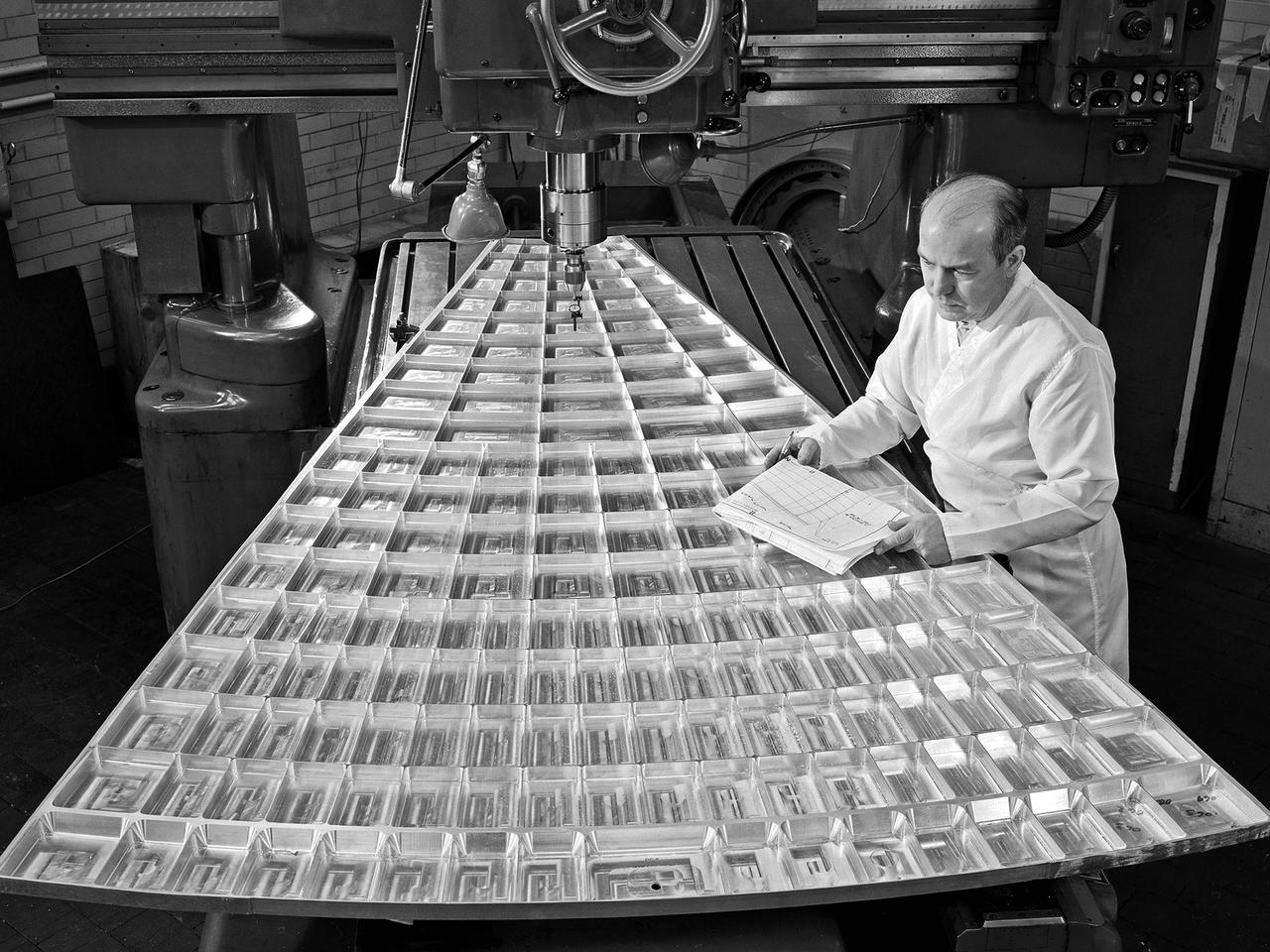
Daniel Bernatowicz, Chief of the Advanced Power Systems Branch at the National Aeronautics and Space Administration (NASA) Lewis Research Center, examines a 20-foot section of a solar mirror being fabricated in the Jig Bore Room of the Technical Services Building. NASA Lewis was conducting a wide-ranging effort to explore methods of generating electrical power for spacecraft. One method employed a large parabolic mirror to concentrate the sun’s energy. The mirror had to remain rigid and withstand micrometeoroids, but remain light and compact enough to be easily launched. In 1963 Bernatowicz and his researchers undertook a program to design a solar mirror to work with the Brayton cycle system on a space station. The mirror in this photograph was prepared for a conference on Advanced Technology in Space Power Systems held at Lewis in late August 1966. Lewis experts discussed advances with batteries, fuel cells, isotope and thermoelectric generators, and the SNAP-8 space power system. Lewis was developing several types of solar mirrors to work with a Brayton cycle electric generating system. The mirror’s 12 sections were shaped using a unique forming process developed at Lewis, coated with an epoxy, and plated with aluminum. The mirror concentrated the Sun's rays on a heat storage receiver containing lithium fluoride. This material was heated to produce power in a turbogenerator system, while additional heat was stored for use when the unit was in the Earth's shadow.

Black holes are tremendous objects whose immense gravity can distort and twist space-time, the fabric that shapes our universe as this chart from NASA NuSTAR and ESA XMM-Newton telescope illustrates.
Under the goals of the Vision for Space Exploration, Ares I is a chief component of the cost-effective space transportation infrastructure being developed by NASA's Constellation Program. This transportation system will safely and reliably carry human explorers back to the moon, and then onward to Mars and other destinations in the solar system. The Ares I effort includes multiple project element teams at NASA centers and contract organizations around the nation, and is managed by the Exploration Launch Projects Office at NASA's Marshall Space Flight Center (MFSC). ATK Launch Systems near Brigham City, Utah, is the prime contractor for the first stage booster. ATK's subcontractor, United Space Alliance of Houston, is designing, developing and testing the parachutes at its facilities at NASA's Kennedy Space Center in Florida. NASA's Johnson Space Center in Houston hosts the Constellation Program and Orion Crew Capsule Project Office and provides test instrumentation and support personnel. Together, these teams are developing vehicle hardware, evolving proven technologies, and testing components and systems. Their work builds on powerful, reliable space shuttle propulsion elements and nearly a half-century of NASA space flight experience and technological advances. Ares I is an inline, two-stage rocket configuration topped by the Crew Exploration Vehicle, its service module, and a launch abort system. This HD video image depicts the preparation and placement of a confidence ring for friction stir welding used in manufacturing aluminum panels that will fabricate the Ares I upper stage barrel. The aluminum panels are manufactured and subjected to confidence tests during which the bent aluminum is stressed to breaking point and thoroughly examined. The panels are manufactured by AMRO Manufacturing located in El Monte, California. (Highest resolution available)
Under the goals of the Vision for Space Exploration, Ares I is a chief component of the cost-effective space transportation infrastructure being developed by NASA's Constellation Program. This transportation system will safely and reliably carry human explorers back to the moon, and then onward to Mars and other destinations in the solar system. The Ares I effort includes multiple project element teams at NASA centers and contract organizations around the nation, and is managed by the Exploration Launch Projects Office at NASA's Marshall Space Flight Center (MFSC). ATK Launch Systems near Brigham City, Utah, is the prime contractor for the first stage booster. ATK's subcontractor, United Space Alliance of Houston, is designing, developing and testing the parachutes at its facilities at NASA's Kennedy Space Center in Florida. NASA's Johnson Space Center in Houston hosts the Constellation Program and Orion Crew Capsule Project Office and provides test instrumentation and support personnel. Together, these teams are developing vehicle hardware, evolving proven technologies, and testing components and systems. Their work builds on powerful, reliable space shuttle propulsion elements and nearly a half-century of NASA space flight experience and technological advances. Ares I is an inline, two-stage rocket configuration topped by the Crew Exploration Vehicle, its service module, and a launch abort system. This HD video image depicts friction stir welding used in manufacturing aluminum panels that will fabricate the Ares I upper stage barrel. The panels are subjected to confidence tests in which the bent aluminum is stressed to breaking point and thoroughly examined. The panels are manufactured by AMRO Manufacturing located in El Monte, California. (Highest resolution available)
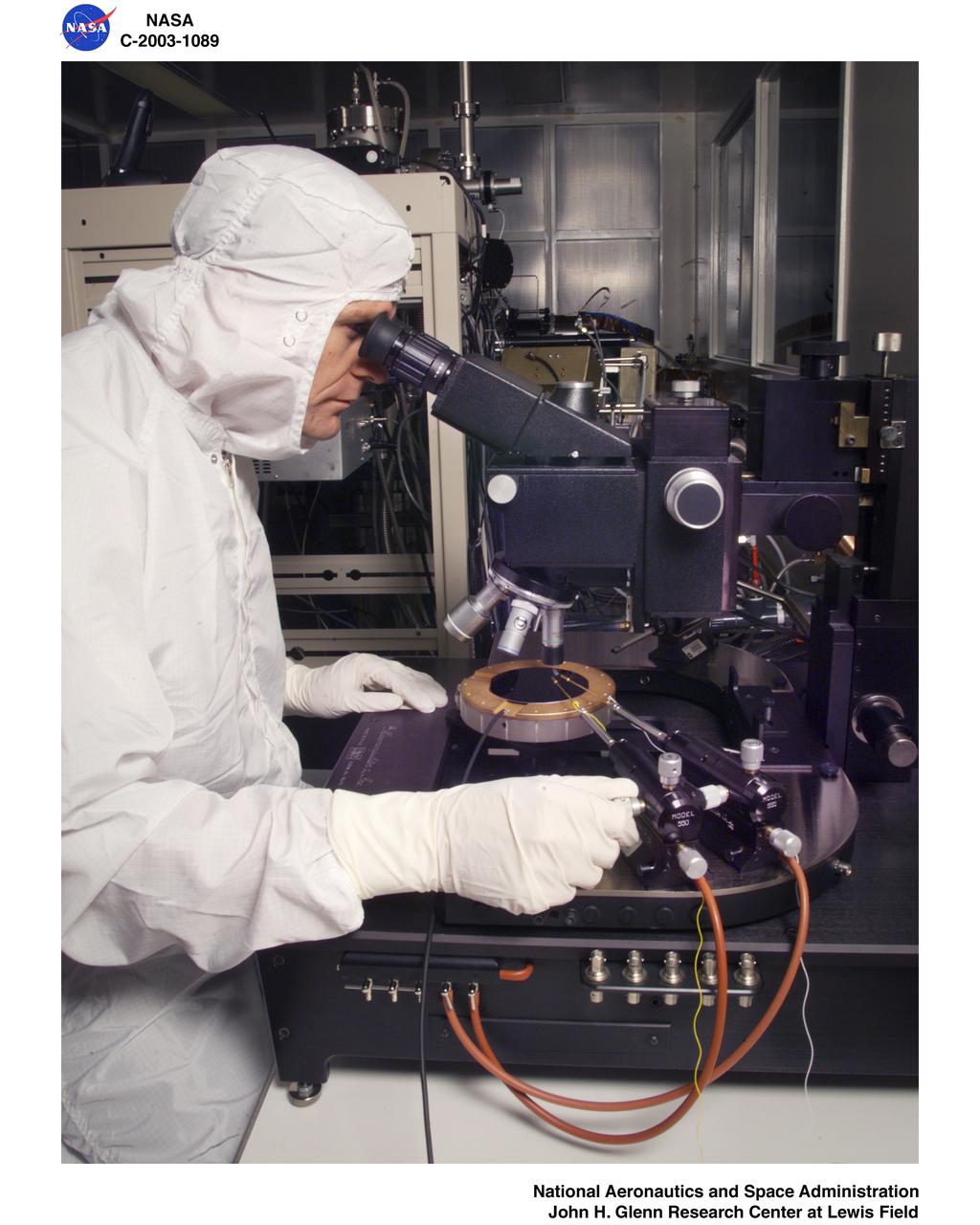
MICROSYSTEMS FABRICATION LABORATORY - PROBE STATION
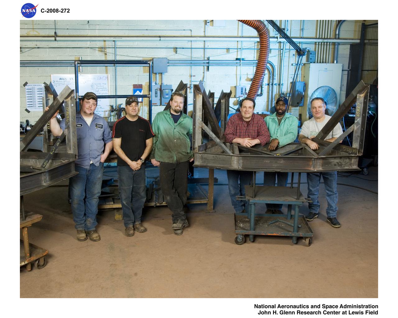
Interior Hardware Fabrication for Ares 1-X Segments
MICROSYSTEMS FABRICATION LABORATORY - REACTIVE ION ETCHER
Interior Hardware Fabrication for Ares 1-X Segments
LCROSS flight hardware in clean room at Ames N-240. EEL personnel fabricating testing components with Jerry Wang of Ames, Engineering Evaluation labLCROSS flight hardware in clean room at Ames N-240. EEL personnel fabricating testing components with Jerry Wang of Ames, Engineering Evaluation lab
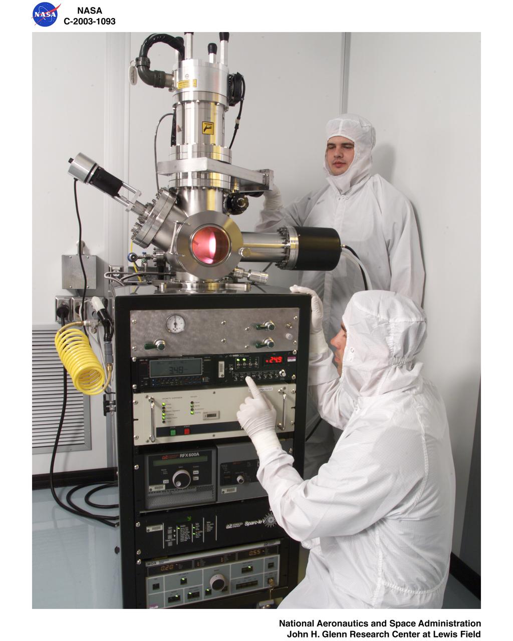
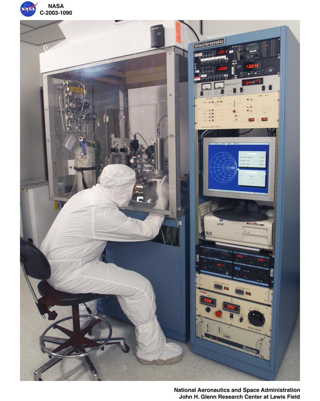
MICROSYSTEMS FABRICATION LABORATORY - PULSED-DC REACTIVE SPUTTERING SYSTEM
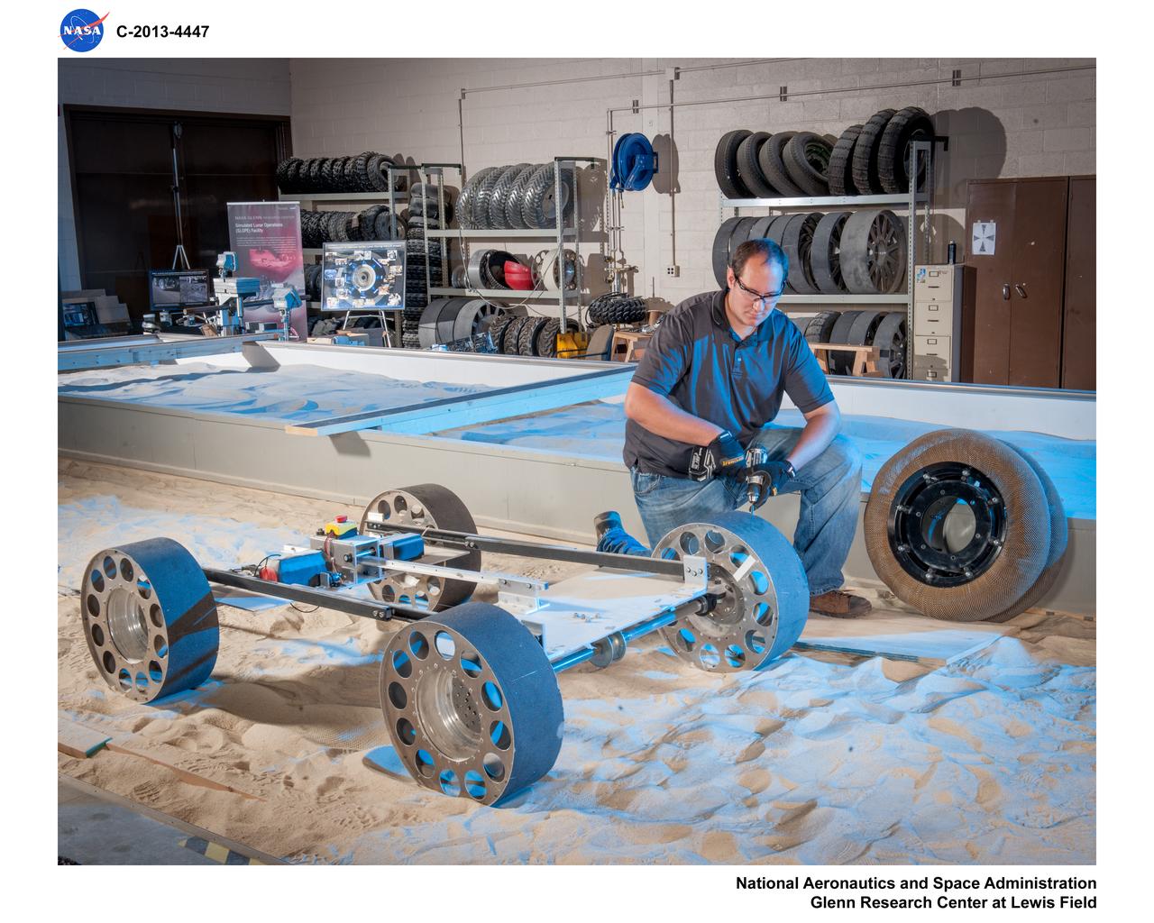
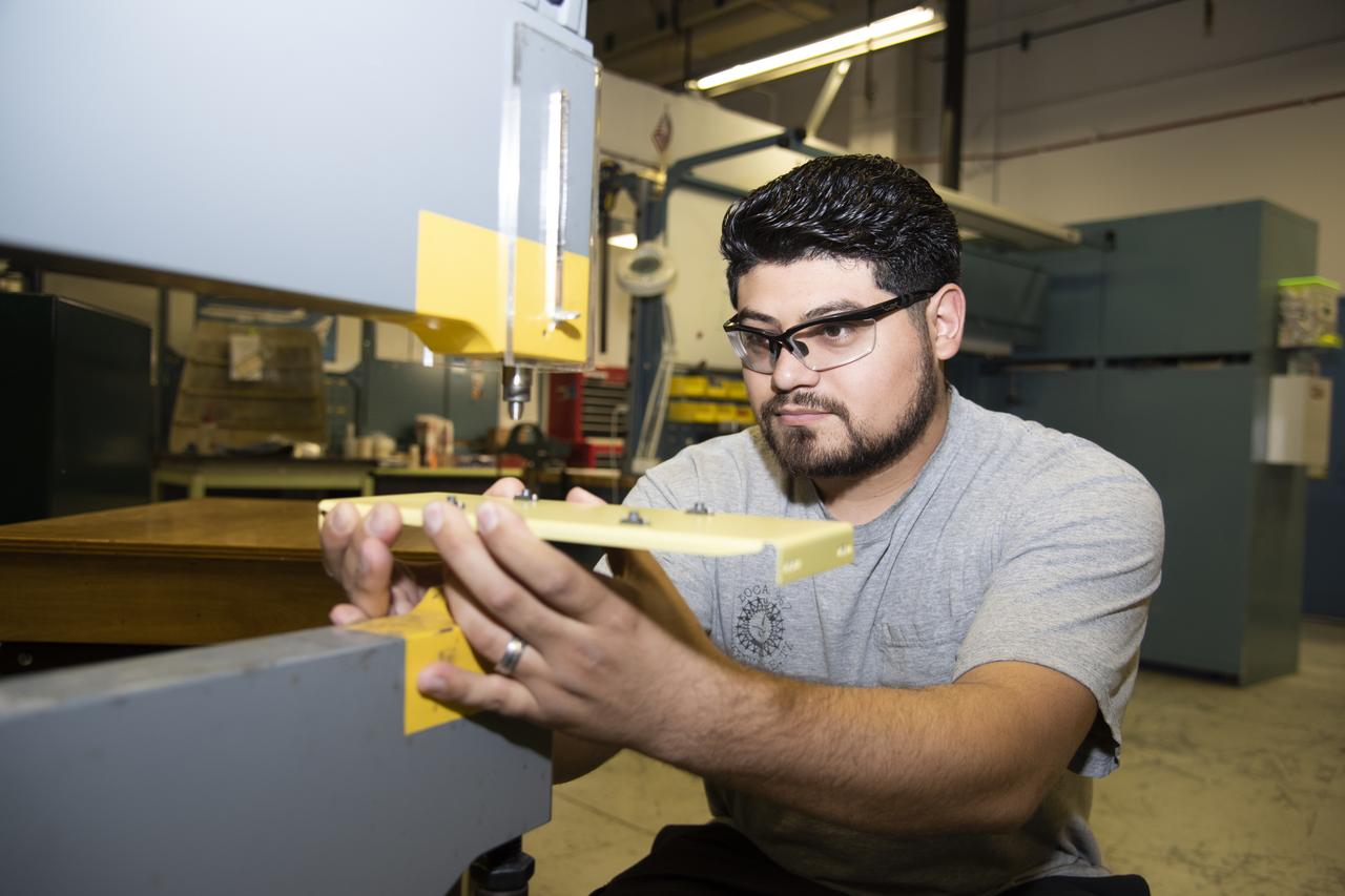
Fabrication of rover spring tires in the Simulated Lunar Operations, SLOPe Lab, Laboratory
Hector Rosas works on fabricating a part for the ER-2 instrumentation panel.
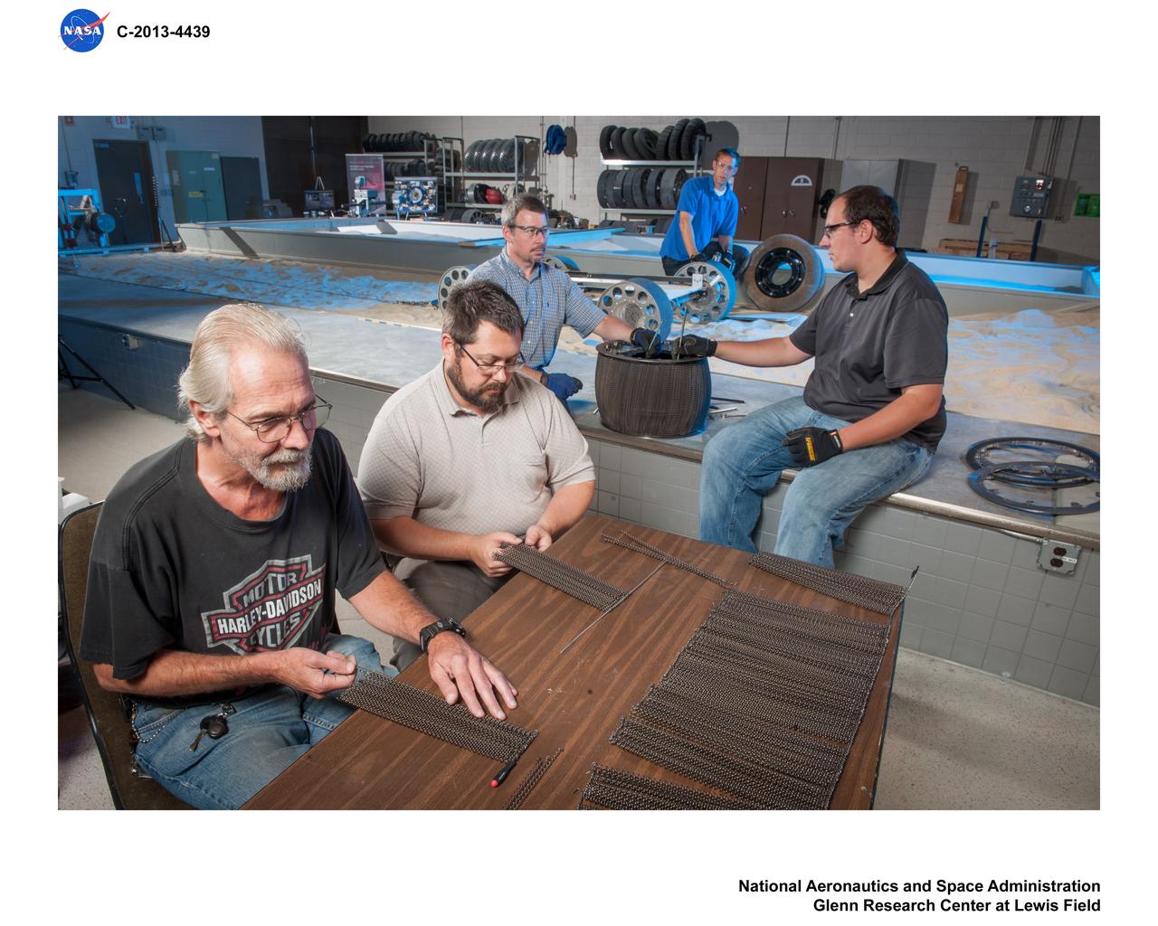
Fabrication of rover spring tires in the Simulated Lunar Operations, SLOPe Lab, Laboratory
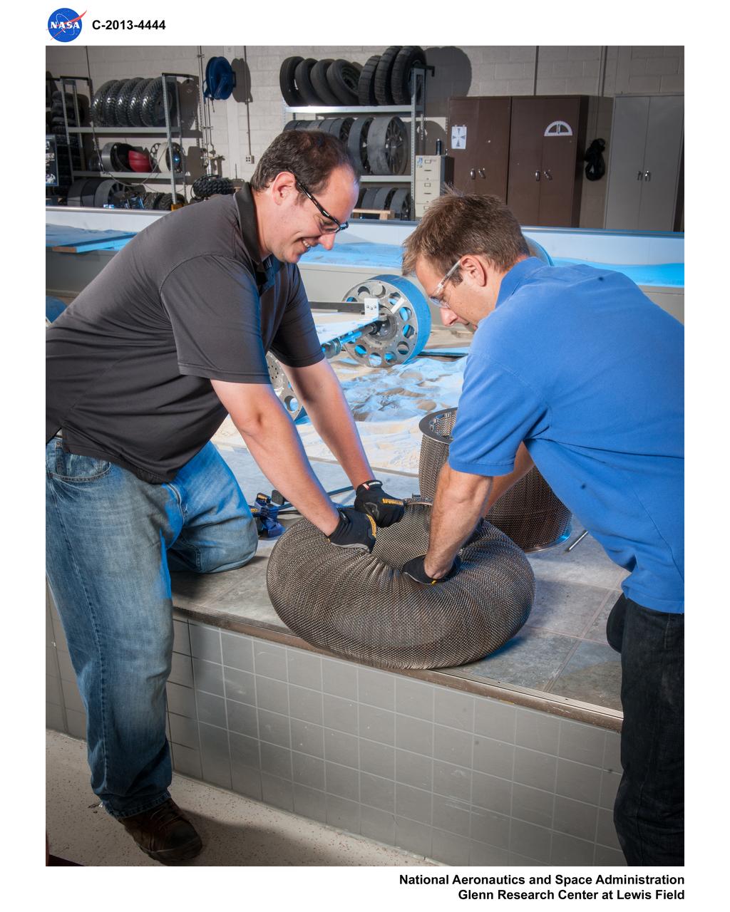
Fabrication of rover spring tires in the Simulated Lunar Operations, SLOPe Lab, Laboratory
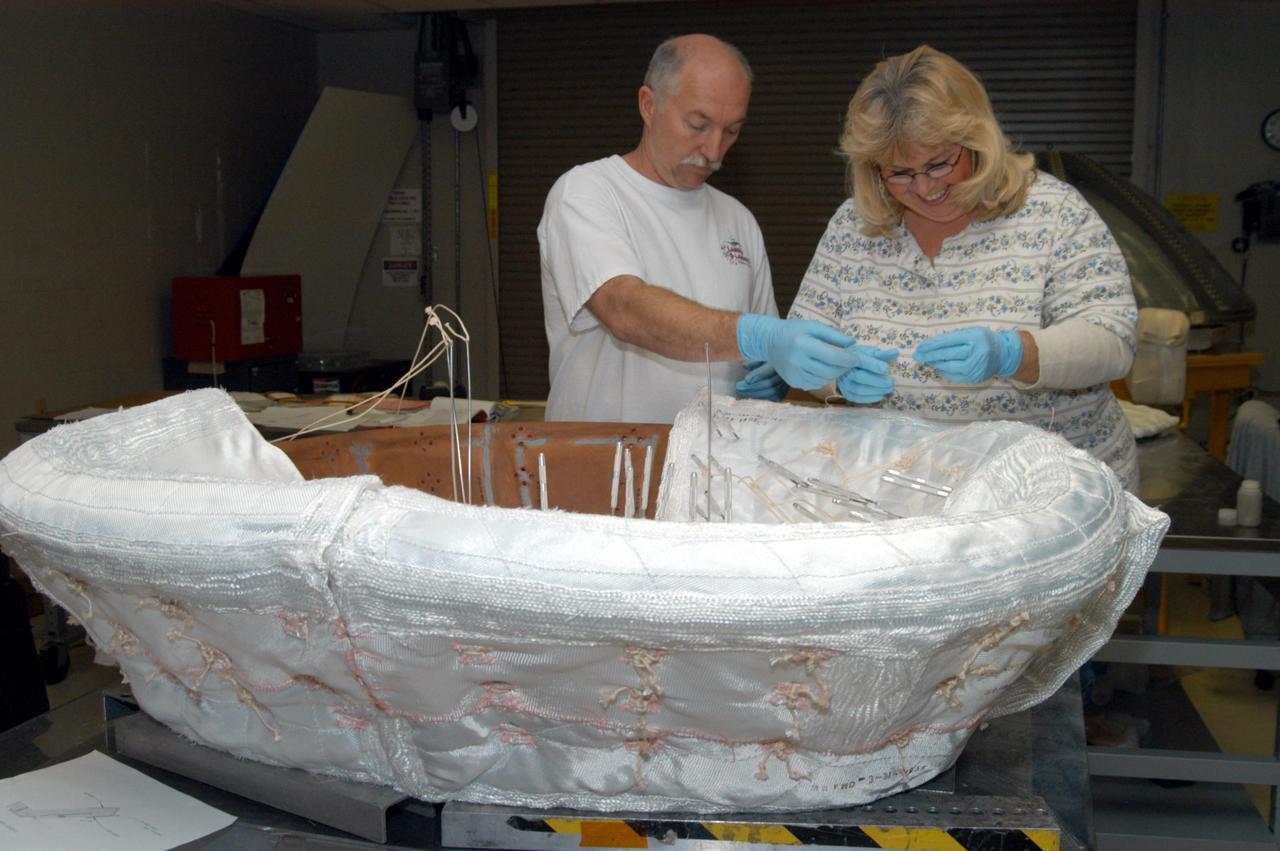
KENNEDY SPACE CENTER, FLA. -- United Space Alliance workers Michael Williams and Ginger Morrison stitch together pieces of insulation blankets inside the ring that fits in the nose cap of Discovery. The blankets consist of layered, pure silica felt sandwiched between a layer of silica fabric (the hot side) and a layer of S-Glass fabric. The blankets are semi-rigid and can be made as large as 30 inches by 30 inches. The blanket is through-stitched with pure silica thread in a 1-inch grid pattern. After fabrication, the blanket is bonded directly to the vehicle structure and finally coated with a high purity silica coating that improves erosion resistance.
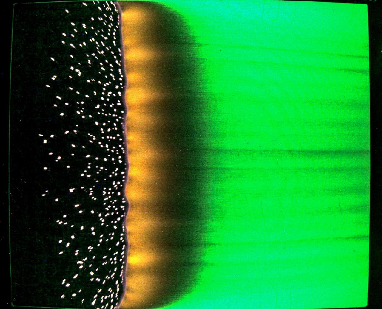
jsc2023e046375 (7/25/2023) --- A sample of fabric burns inside Spacecraft Fire Experiment-IV (Saffire-IV). The sample is a composite fabric made of cotton and fiberglass and is 40 cm wide. The image appears green because green LED lights are used to illuminate the sample during a burn. The flame appears orange in this image and the black region to the right of the flame is the cotton in the sample beginning to heat and char. The bright specks to the left of the flame are smoldering cotton that remains on the fiberglass substrate after the flame passes. In Saffire-VI, this fabric is burned at higher oxygen concentrations. Researchers aim to study realistic flame spread to aid the development of fire safety equipment and strategies for future spacecraft.
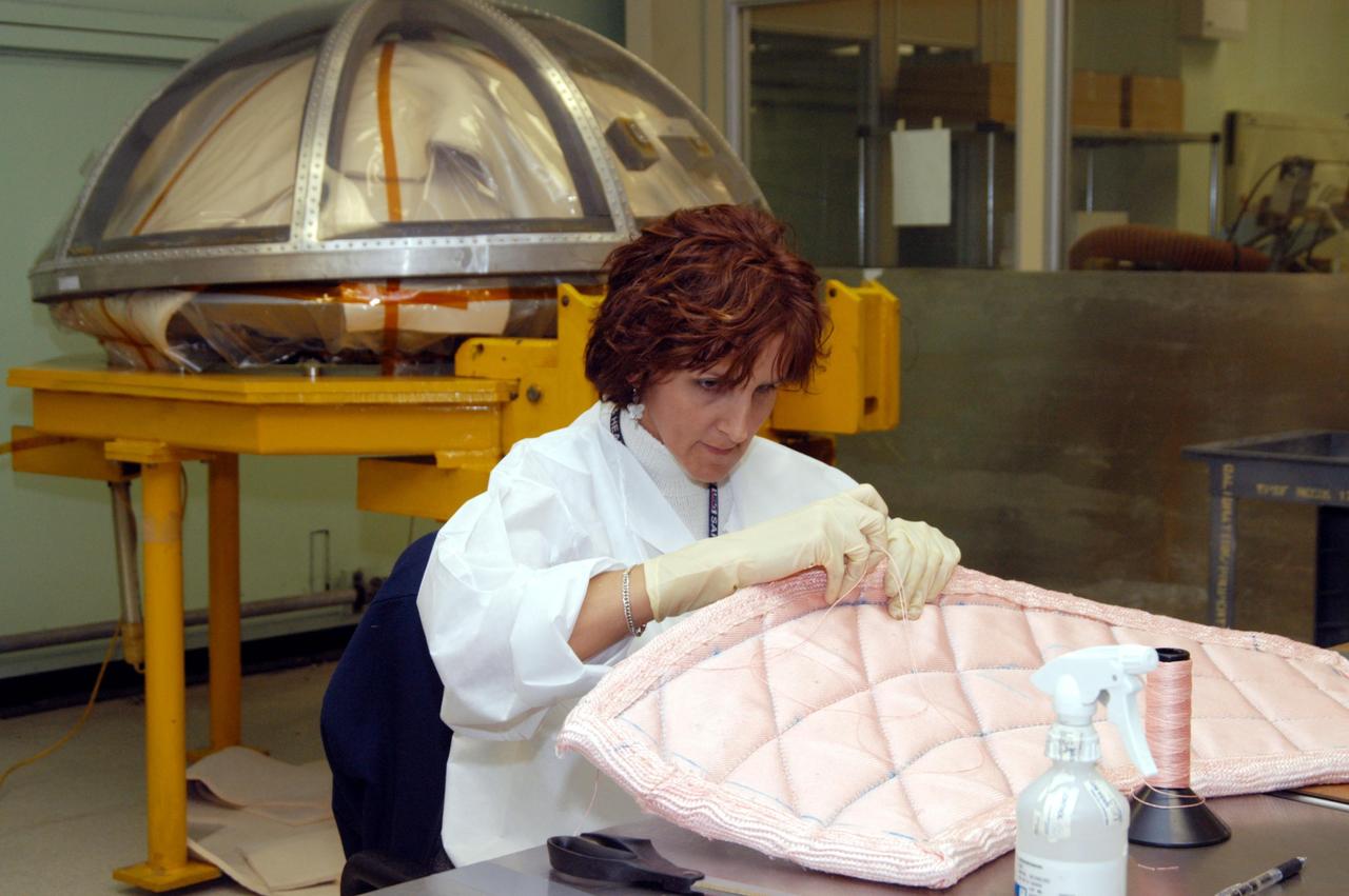
KENNEDY SPACE CENTER, FLA. -- In the Thermal Protection System Facility, Pilar Ryan, with United Space Alliance, stitches a piece of insulation blanket for Atlantis. The blankets will be sewn into the inside of a ring that will be inserted in the nose cap. In the background is a cover for the nose cap. The blankets consist of layered, pure silica felt sandwiched between a layer of silica fabric (the hot side) and a layer of S-Glass fabric. The blankets are semi-rigid and can be made as large as 30 inches by 30 inches. The blanket is through-stitched with pure silica thread in a 1-inch grid pattern. After fabrication, the blanket is bonded directly to the vehicle structure and finally coated with a high purity silica coating that improves erosion resistance.

KENNEDY SPACE CENTER, FLA. -- A closeup of the stitching being done on pieces of insulation blankets inside the ring that fits in the nose cap of Discovery. The blankets consist of layered, pure silica felt sandwiched between a layer of silica fabric (the hot side) and a layer of S-Glass fabric. The blankets are semi-rigid and can be made as large as 30 inches by 30 inches. The blanket is through-stitched with pure silica thread in a 1-inch grid pattern. After fabrication, the blanket is bonded directly to the vehicle structure and finally coated with a high purity silica coating that improves erosion resistance.
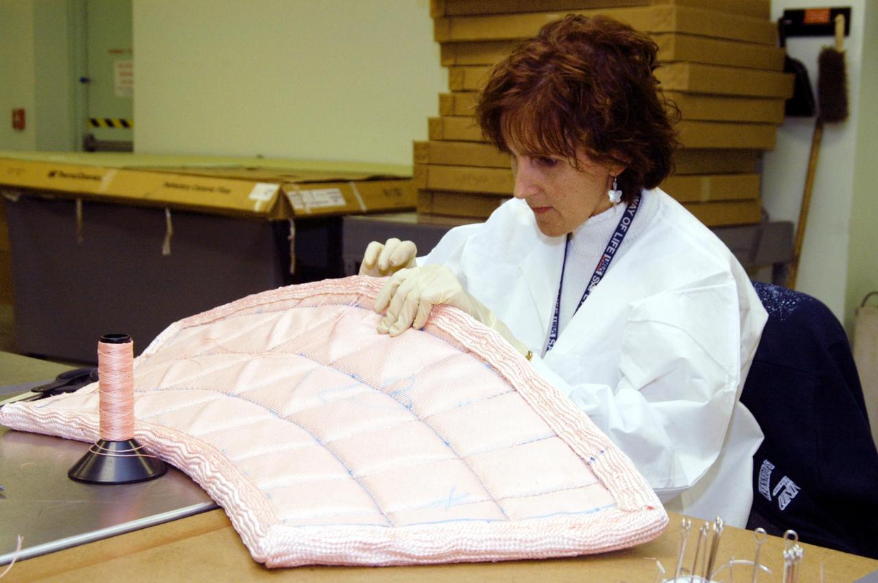
KENNEDY SPACE CENTER, FLA. -- In the Thermal Protection System Facility, Pilar Ryan, with United Space Alliance, stitches a piece of insulation blanket for Atlantis's nose cap. The blankets consist of layered, pure silica felt sandwiched between a layer of silica fabric (the hot side) and a layer of S-Glass fabric. The blankets are semi-rigid and can be made as large as 30 inches by 30 inches. The blanket is through-stitched with pure silica thread in a 1-inch grid pattern. After fabrication, the blanket is bonded directly to the vehicle structure and finally coated with a high purity silica coating that improves erosion resistance.
KENNEDY SPACE CENTER, FLA. -- Damon Petty, with United Space Alliance, prepares the cover of another insulation blanket in the “oven” prior to heat cleaning. The blankets fit inside the nose cap of an orbiter. They consist of layered, pure silica felt sandwiched between a layer of silica fabric (the hot side) and a layer of S-Glass fabric. The blanket is through-stitched with pure silica thread in a 1-inch grid pattern. After fabrication, the blanket is bonded directly to the vehicle structure and finally coated with a high purity silica coating that improves erosion resistance. The blankets are semi-rigid and can be made as large as 30 inches by 30 inches.
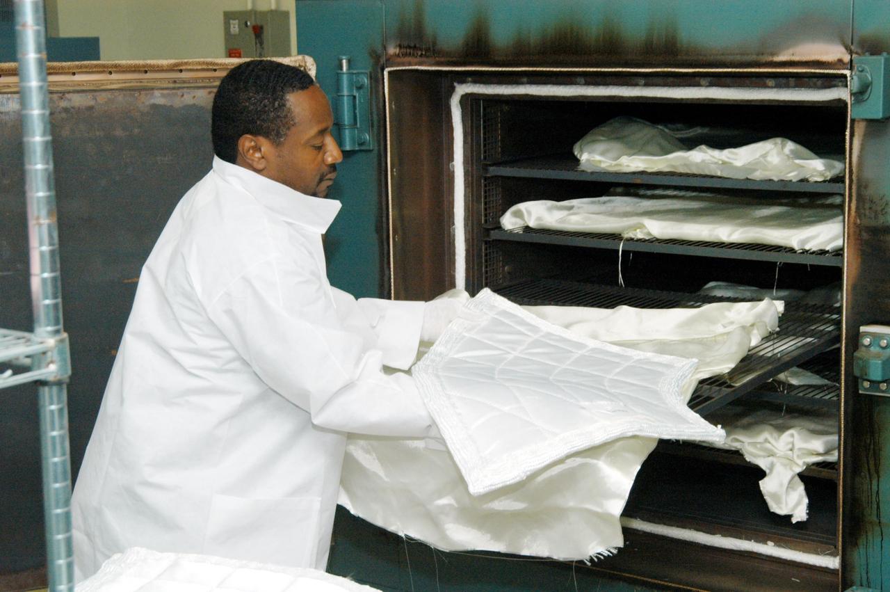
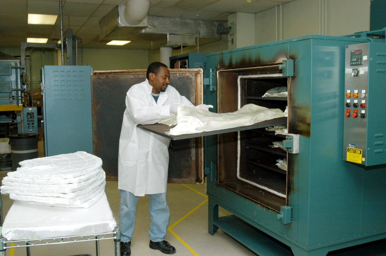
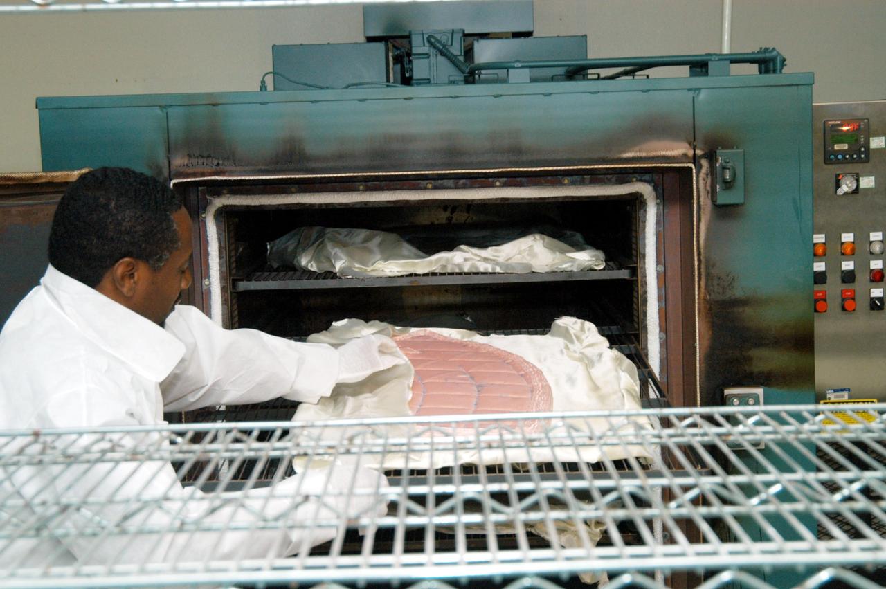
KENNEDY SPACE CENTER, FLA. -- Damon Petty, with United Space Alliance, removes a piece of insulation blanket from an “oven” after heat cleaning. The blankets fit inside the nose cap of an orbiter. They consist of layered, pure silica felt sandwiched between a layer of silica fabric (the hot side) and a layer of S-Glass fabric. The blanket is through-stitched with pure silica thread in a 1-inch grid pattern. After fabrication, the blanket is bonded directly to the vehicle structure and finally coated with a high purity silica coating that improves erosion resistance. The blankets are semi-rigid and can be made as large as 30 inches by 30 inches.
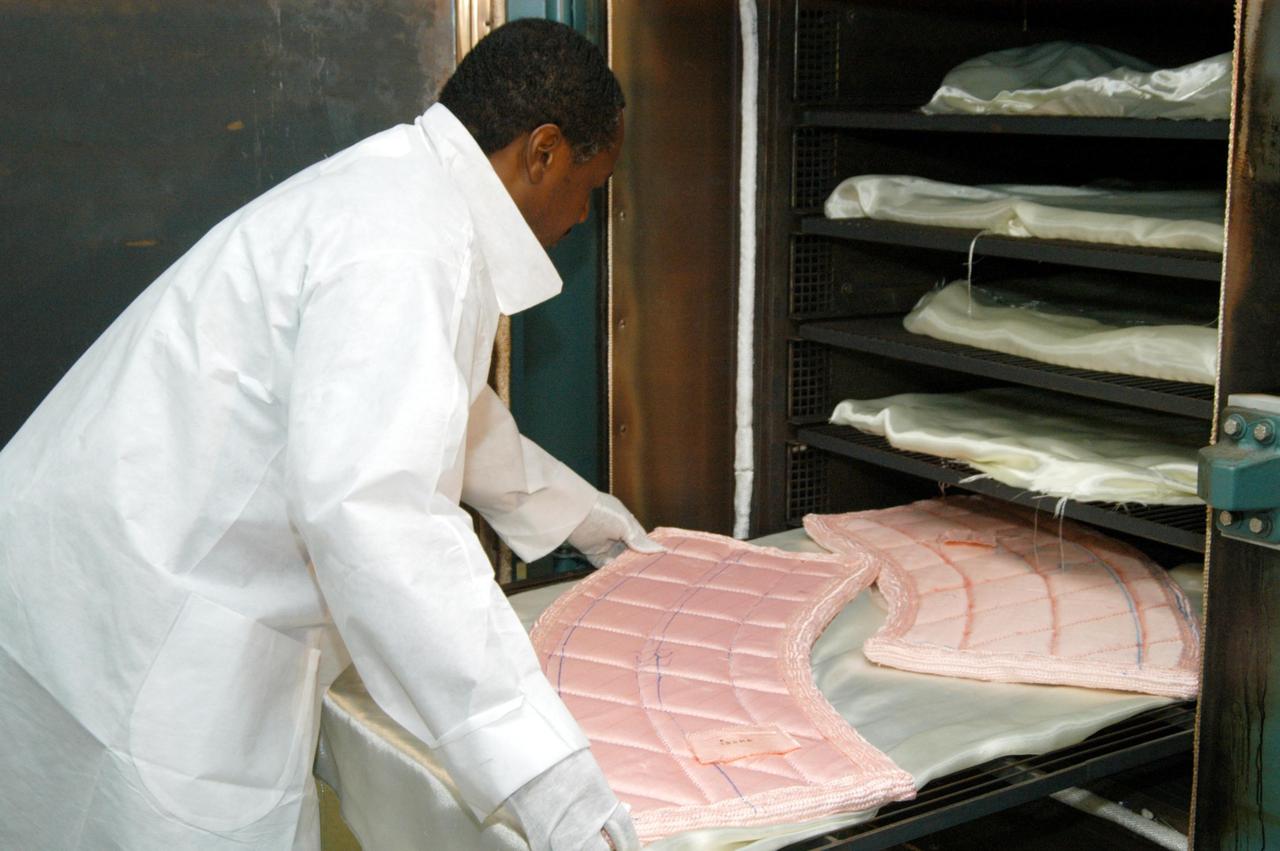
KENNEDY SPACE CENTER, FLA. -- Damon Petty, with United Space Alliance, places pieces of insulation blanket into an “oven” for heat cleaning. The blankets fit inside the nose cap of an orbiter. They consist of layered, pure silica felt sandwiched between a layer of silica fabric (the hot side) and a layer of S-Glass fabric. The blanket is through-stitched with pure silica thread in a 1-inch grid pattern. After fabrication, the blanket is bonded directly to the vehicle structure and finally coated with a high purity silica coating that improves erosion resistance. The blankets are semi-rigid and can be made as large as 30 inches by 30 inches.
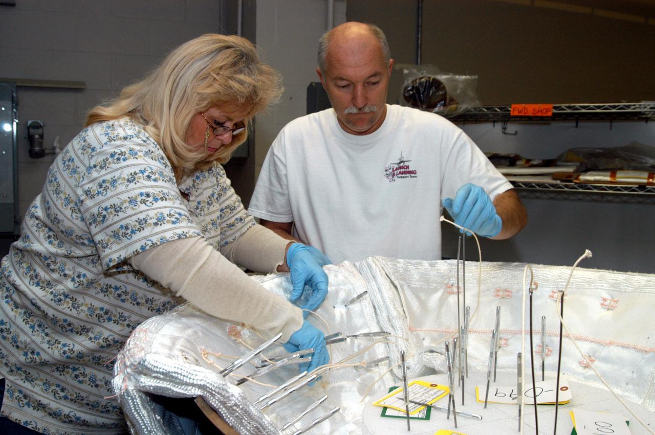
KENNEDY SPACE CENTER, FLA. -- United Space Alliance workers Ginger Morrison and Michael Williams stitch together pieces of insulation blankets inside the ring that fits in the nose cap of Discovery. The blankets consist of layered, pure silica felt sandwiched between a layer of silica fabric (the hot side) and a layer of S-Glass fabric. The blankets are semi-rigid and can be made as large as 30 inches by 30 inches. The blanket is through-stitched with pure silica thread in a 1-inch grid pattern. After fabrication, the blanket is bonded directly to the vehicle structure and finally coated with a high purity silica coating that improves erosion resistance.
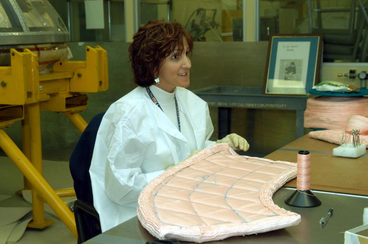
KENNEDY SPACE CENTER, FLA. -- In the Thermal Protection System Facility, Pilar Ryan, with United Space Alliance, stitches a piece of insulation blanket for Atlantis' nose cap. Behind her is a cover for the nose cap. The blankets consist of layered, pure silica felt sandwiched between a layer of silica fabric (the hot side) and a layer of S-Glass fabric. The blankets are semi-rigid and can be made as large as 30 inches by 30 inches. The blanket is through-stitched with pure silica thread in a 1-inch grid pattern. After fabrication, the blanket is bonded directly to the vehicle structure and finally coated with a high purity silica coating that improves erosion resistance.
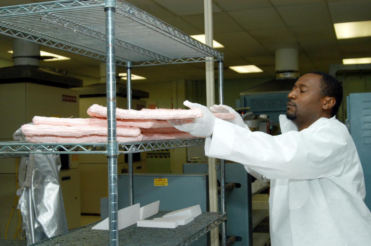
KENNEDY SPACE CENTER, FLA. -- Damon Petty, with United Space Alliance, removes an insulation blanket from a shelf prior to heat cleaning and waterproofing. The blankets fit inside the nose cap of an orbiter. They consist of layered, pure silica felt sandwiched between a layer of silica fabric (the hot side) and a layer of S-Glass fabric. The blanket is through-stitched with pure silica thread in a 1-inch grid pattern. After fabrication, the blanket is bonded directly to the vehicle structure and finally coated with a high purity silica coating that improves erosion resistance. The blankets are semi-rigid and can be made as large as 30 inches by 30 inches.

KENNEDY SPACE CENTER, FLA. -- United Space Alliance workers Ginger Morrison and Michael Williams stitch together pieces of insulation blankets inside the ring that fits in the nose cap of Discovery. The blankets consist of layered, pure silica felt sandwiched between a layer of silica fabric (the hot side) and a layer of S-Glass fabric. The blanket is through-stitched with pure silica thread in a 1-inch grid pattern. After fabrication, the blanket is bonded directly to the vehicle structure and finally coated with a high purity silica coating that improves erosion resistance. The blankets are semi-rigid and can be made as large as 30 inches by 30 inches.
Craftsmen work in the wood model shop at the National Advisory Committee for Aeronautics (NACA) Lewis Flight Propulsion Laboratory. The Fabrication Division created almost all of the equipment and models used at the laboratory. The Fabrication Shop building contained a number of specialized shops in the 1940s and 1950s. These included a Machine Shop, Sheet Metal Shop, Wood Model and Pattern Shop, Instrument Shop, Thermocouple Shop, Heat Treating Shop, Metallurgical Laboratory, and Fabrication Office. The Wood Model and Pattern Shop created everything from control panels and cabinets to aircraft models molds for sheet metal work.

KENNEDY SPACE CENTER, FLA. -- Damon Petty, with United Space Alliance, removes another insulation blanket from a shelf prior to heat cleaning and waterproofing. The blankets fit inside the nose cap of an orbiter. They consist of layered, pure silica felt sandwiched between a layer of silica fabric (the hot side) and a layer of S-Glass fabric. The blanket is through-stitched with pure silica thread in a 1-inch grid pattern. After fabrication, the blanket is bonded directly to the vehicle structure and finally coated with a high purity silica coating that improves erosion resistance. The blankets are semi-rigid and can be made as large as 30 inches by 30 inches.
KENNEDY SPACE CENTER, FLA. -- Damon Petty, with United Space Alliance, covers another insulation blanket in the “oven” prior to heat cleaning. The blankets fit inside the nose cap of an orbiter. They consist of layered, pure silica felt sandwiched between a layer of silica fabric (the hot side) and a layer of S-Glass fabric. The blanket is through-stitched with pure silica thread in a 1-inch grid pattern. After fabrication, the blanket is bonded directly to the vehicle structure and finally coated with a high purity silica coating that improves erosion resistance. The blankets are semi-rigid and can be made as large as 30 inches by 30 inches.

KENNEDY SPACE CENTER, FLA. -- Damon Petty, with United Space Alliance, gets ready to place insulation blankets on the shelf after they have been heated. The blankets fit inside the nose cap of an orbiter. They consist of layered, pure silica felt sandwiched between a layer of silica fabric (the hot side) and a layer of S-Glass fabric. The blanket is through-stitched with pure silica thread in a 1-inch grid pattern. After fabrication, the blanket is bonded directly to the vehicle structure and finally coated with a high purity silica coating that improves erosion resistance. The blankets are semi-rigid and can be made as large as 30 inches by 30 inches.

KENNEDY SPACE CENTER, FLA. -- In the Thermal Protection System Facility, Pilar Ryan, with United Space Alliance, stitches a piece of insulation blanket for Atlantis. In the foreground is a ring inside of which the blankets will be sewn to fit in the orbiter's nose cap. The blankets consist of layered, pure silica felt sandwiched between a layer of silica fabric (the hot side) and a layer of S-Glass fabric. The blankets are semi-rigid and can be made as large as 30 inches by 30 inches. The blanket is through-stitched with pure silica thread in a 1-inch grid pattern. After fabrication, the blanket is bonded directly to the vehicle structure and finally coated with a high purity silica coating that improves erosion resistance.
Under the goals of the Vision for Space Exploration, Ares I is a chief component of the cost-effective space transportation infrastructure being developed by NASA's Constellation Program. This transportation system will safely and reliably carry human explorers back to the moon, and then onward to Mars and other destinations in the solar system. The Ares I effort includes multiple project element teams at NASA centers and contract organizations around the nation, and is managed by the Exploration Launch Projects Office at NASA's Marshall Space Flight Center (MFSC). ATK Launch Systems near Brigham City, Utah, is the prime contractor for the first stage booster. ATK's subcontractor, United Space Alliance of Houston, is designing, developing and testing the parachutes at its facilities at NASA's Kennedy Space Center in Florida. NASA's Johnson Space Center in Houston hosts the Constellation Program and Orion Crew Capsule Project Office and provides test instrumentation and support personnel. Together, these teams are developing vehicle hardware, evolving proven technologies, and testing components and systems. Their work builds on powerful, reliable space shuttle propulsion elements and nearly a half-century of NASA space flight experience and technological advances. Ares I is an inline, two-stage rocket configuration topped by the Crew Exploration Vehicle, its service module, and a launch abort system. This HD video image depicts the manufacturing of aluminum panels that will be used to form the Ares I barrel. The panels are manufacturing process demonstration articles that will undergo testing until perfected. The panels are built by AMRO Manufacturing located in El Monte, California. (Highest resolution available)
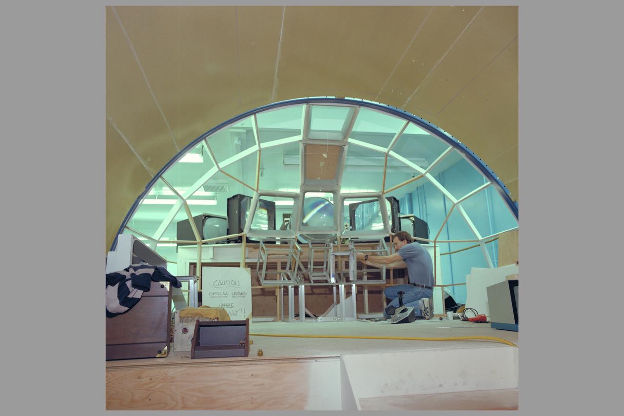
SPACE STATION MODEL MOCKUPS N-239A PROX-OPS (PROXIMITY OPERATIONS SIMULATOR) FABRICATION WITH PHIL CULBERTSON

PIONEER 10 SPACECRAFT FINAL ASSEMBLY AT TRW (TRW SYSTEMS GROUP, REDONDO BEACH, CALIFORNIA DESIGNED AND FABRICATED THE PIONEER SPACECRAFT)
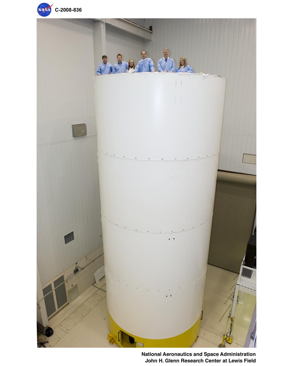
Constellation program office tour of Ares 1-X fabrication facility and segment Super Stack
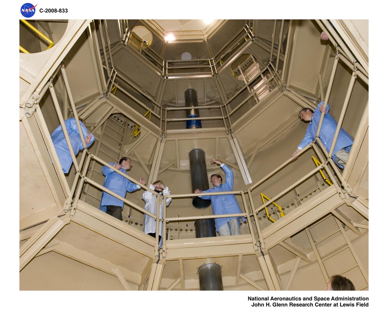
Constellation program office tour of Ares 1-X fabrication facility and segment Super Stack
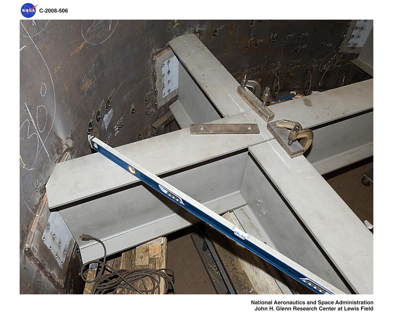
Ares 1-X segment US-7 showing fabrication of internal support for the ballast can
Ares 1-X segment US-7 showing fabrication of internal support for the ballast can
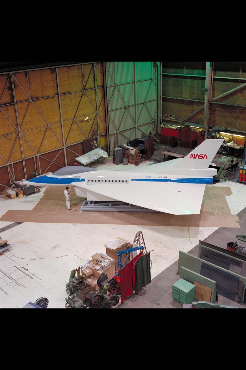
General Dynamics E-7 Full-scale STOVL fighter model fabrication at Ames Model Shop