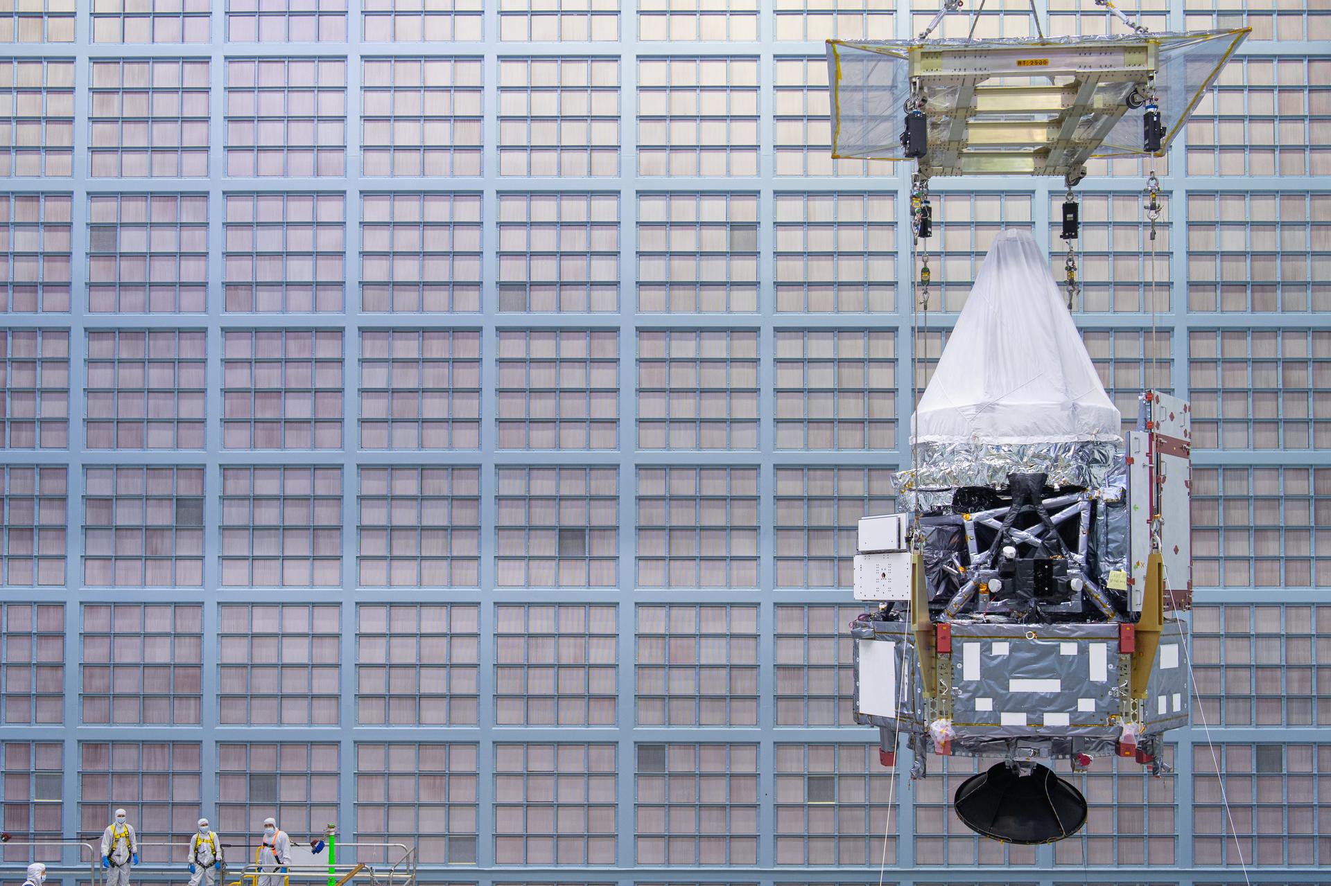
The Roman Space Telescope's Spacecraft Bus and Integrated Payload Assembly is crane lifted inside the cleanroom at Goddard Space Flight Center, Greenbelt Md., June 12, 2025. This photo has been approved for public release. NASA/Mike Guinto
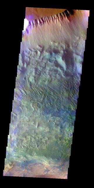
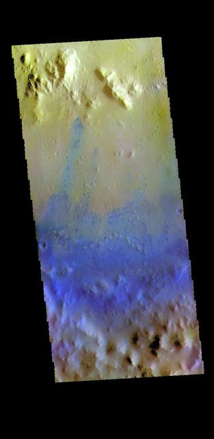
The THEMIS VIS camera contains 5 filters. The data from different filters can be combined in multiple ways to create a false color image. This false color image from NASA 2001 Mars Odyssey spacecraft shows part of the northern wall of Candor Chasma. Orbit Number: 7381 Latitude: -4.72297 Longitude: 283.559 Instrument: VIS Captured: 2003-08-14 03:05 http://photojournal.jpl.nasa.gov/catalog/PIA19481
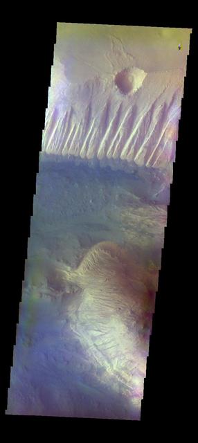
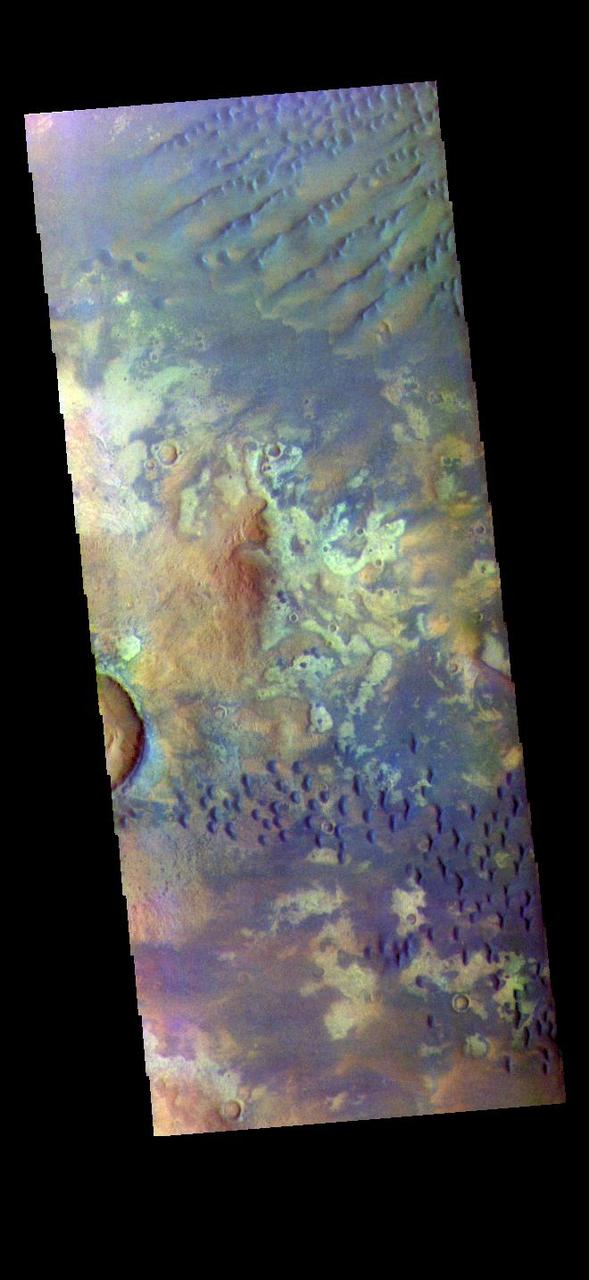
The THEMIS VIS camera contains 5 filters. The data from different filters can be combined in multiple ways to create a false color image. These false color images may reveal subtle variations of the surface not easily identified in a single band image. Today's false color image shows part of Candor Chasma. The bright tones in this image are the canyon walls, the bluer material is sand and other debris on the canyon floor. Orbit Number: 15156 Latitude: -6.9737 Longitude: 288.593 Instrument: VIS Captured: 2005-05-15 05:54 http://photojournal.jpl.nasa.gov/catalog/PIA20103
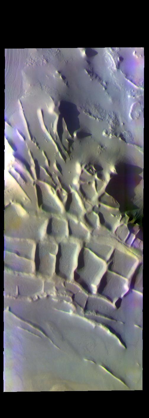
The THEMIS VIS camera contains 5 filters. The data from different filters can be combined in multiple ways to create a false color image. These false color images may reveal subtle variations of the surface not easily identified in a single band image. Today's false color image shows part of Angustus Labyrinthus. The intersecting ridges were most likely formed due to tectonic activity. When this feature was first observed by the Mariner 9 orbiter, project scientists informally dubbed it "the Inca City." It is very common to 'see' familiar objects in unfamiliar images, akin to seeing a 'face' in a wall outlet. To the scientists the orthogonal shapes resembled buildings. Orbit Number: 67658 Latitude: -81.392 Longitude: 296.2 Instrument: VIS Captured: 2017-03-15 21:34 https://photojournal.jpl.nasa.gov/catalog/PIA24073
This false color image shows part of the inner rim (bottom of image), central peak ring (top of image) and floor of Sagan Crater. This 90 km (56 miles) crater was named for Carl Sagan. Peak rings are created during impact by uplift of the center and slumping of the walls of large craters (~100 km). The small blue dots are sand dunes. Basaltic sands are typically blue in this false color combination. The THEMIS VIS camera contains 5 filters. The data from different filters can be combined in multiple ways to create a false color image. These false color images may reveal subtle variations of the surface not easily identified in a single band image. Orbit Number: 64034 Latitude: 10.3433 Longitude: 329.431 Instrument: VIS Captured: 2016-05-21 08:58 https://photojournal.jpl.nasa.gov/catalog/PIA23598
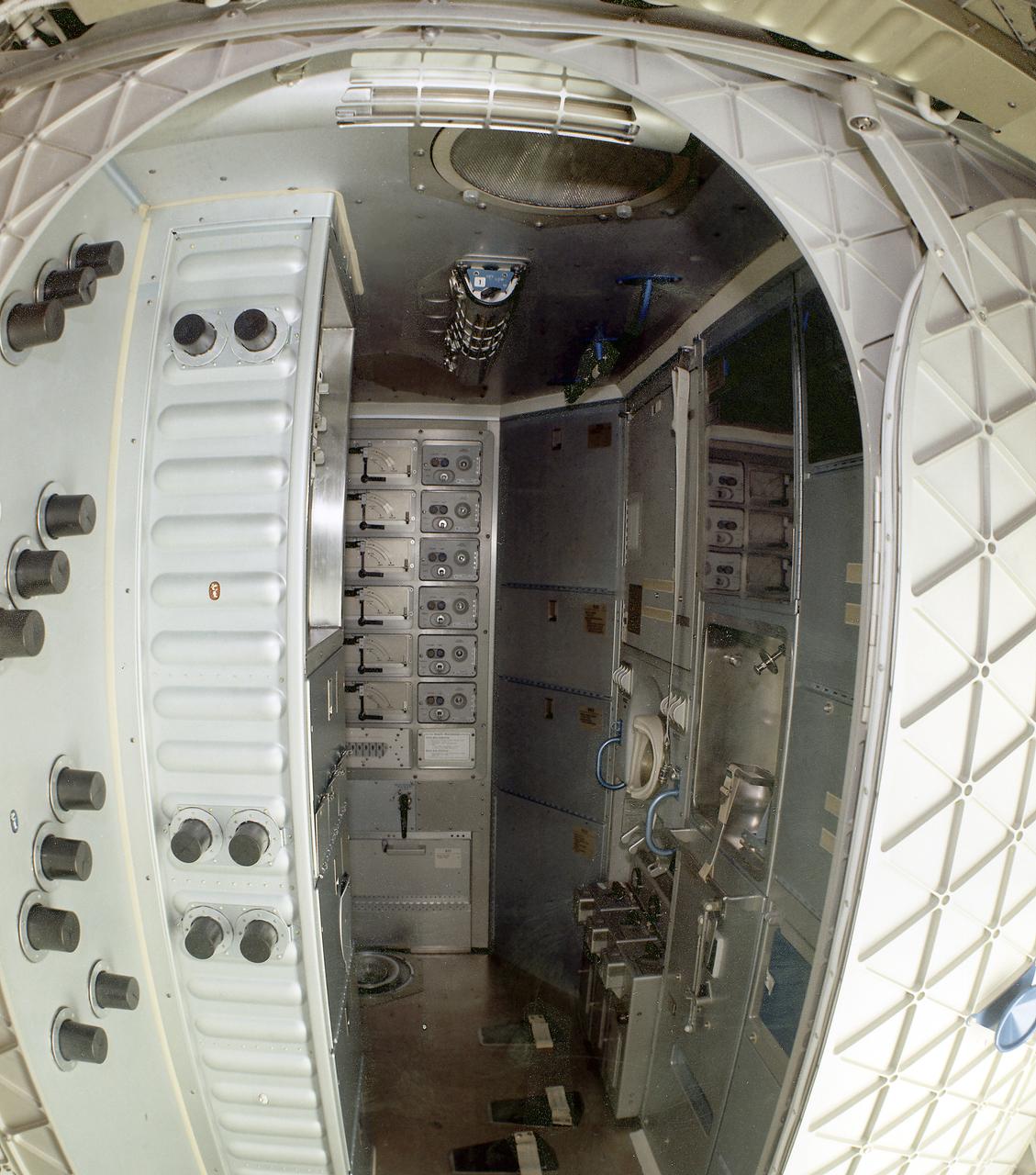
This image is a wide-angle view of the Orbital Workshop waste management compartment. The waste management facilities presented a unique challenge to spacecraft designers. In addition to collection of liquid and solid human wastes, there was a medical requirement to dry all solid human waste products and to return the residue to Earth for examination. Liquid human waste (urine) was frozen for return to Earth. Total quantities of each astronaut's liquid and solid wastes were precisely measured. Cabin air was drawn into the toilet, shown on the wall at right in this photograph, and over the waste products to generate a flow of the waste in the desired direction. The air was then filtered for odor control and antiseptic purposes prior to being discharged back into the cabin.
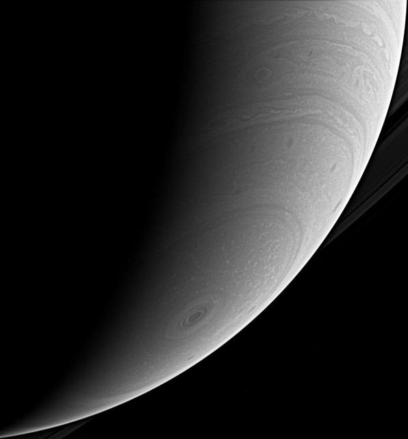
This beautiful look at Saturn's south polar atmosphere shows the hurricane-like polar storm swirling there. Sunlight highlights its high cloud walls, especially around the 10 o'clock position. The image was taken with the Cassini spacecraft wide-angle camera using a spectral filter sensitive to wavelengths of infrared light centered at 939 nanometers. The image was taken on Jan. 30, 2007 at a distance of approximately 1.1 million kilometers (700,000 miles) from Saturn. Image scale is 61 kilometers (38 miles) per pixel. http://photojournal.jpl.nasa.gov/catalog/PIA08892
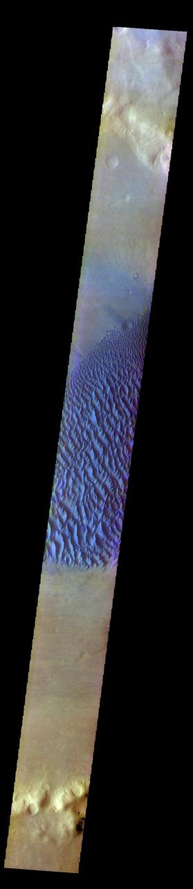
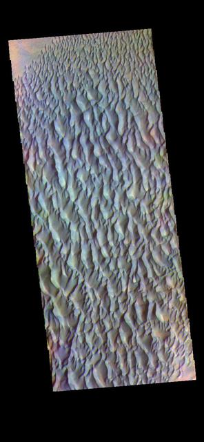
The THEMIS VIS camera contains 5 filters. The data from different filters can be combined in multiple ways to create a false color image. These false color images may reveal subtle variations of the surface not easily identified in a single band image. Today's false color image shows part of the floor of Kaiser Crater. Kaiser Crater is 207 km (129 miles) in diameter and is located in Noachis Terra west of Hellas Planitia. This sand dune field is one of several regions of sand dunes located on the southern part of the crater floor. The image also shows the complex crater floor beneath the dunes. These dunes are composed of basaltic sand that has collected in the bottom of the crater. The topographic depression of the crater forms a sand trap that prevents the sand from escaping. Dune fields are common in the bottoms of craters on Mars and appear as dark splotches that often lean up against the downwind walls of the craters. Dunes are useful for studying both the geology and meteorology of Mars. The sand forms by erosion of larger rocks, but it is unclear when and where this erosion took place on Mars or how such large volumes of sand could be formed. The dunes also indicate the local wind directions by their morphology. The THEMIS VIS camera is capable of capturing color images of the Martian surface using five different color filters. In this mode of operation, the spatial resolution and coverage of the image must be reduced to accommodate the additional data volume produced from using multiple filters. To make a color image, three of the five filter images (each in grayscale) are selected. Each is contrast enhanced and then converted to a red, green, or blue intensity image. These three images are then combined to produce a full color, single image. Because the THEMIS color filters don't span the full range of colors seen by the human eye, a color THEMIS image does not represent true color. Also, because each single-filter image is contrast enhanced before inclusion in the three-color image, the apparent color variation of the scene is exaggerated. Nevertheless, the color variation that does appear is representative of some change in color, however subtle, in the actual scene. Note that the long edges of THEMIS color images typically contain color artifacts that do not represent surface variation. Orbit Number: 90294 Latitude: -46.9314 Longitude: 18.9731 Instrument: VIS Captured: 2022-04-23 02:29 https://photojournal.jpl.nasa.gov/catalog/PIA26058
The THEMIS VIS camera contains 5 filters. The data from different filters can be combined in multiple ways to create a false color image. These false color images may reveal subtle variations of the surface not easily identified in a single band image. Today's false color image shows Proctor Crater and the large dune field on the crater floor. These dunes are composed of basaltic sand that has collected in the bottom of the crater. The topographic depression of the crater forms a sand trap that prevents the sand from escaping. Dune fields are common in the bottoms of craters on Mars and appear as dark splotches that lean up against the downwind walls of the craters. Dunes are useful for studying both the geology and meteorology of Mars. The sand forms by erosion of larger rocks, but it is unclear when and where this erosion took place on Mars or how such large volumes of sand could be formed. The dunes also indicate the local wind directions by their morphology. In this case, there are few clear slipfaces that would indicate the downwind direction. The crests of the dunes also typically run north-south in the image. This dune form indicates that there are probably two prevailing wind directions that run east and west (left to right and right to left). Proctor Crater is located in Noachis Terra and is 172km (107miles) in diameter. The THEMIS VIS camera is capable of capturing color images of the Martian surface using five different color filters. In this mode of operation, the spatial resolution and coverage of the image must be reduced to accommodate the additional data volume produced from using multiple filters. To make a color image, three of the five filter images (each in grayscale) are selected. Each is contrast enhanced and then converted to a red, green, or blue intensity image. These three images are then combined to produce a full color, single image. Because the THEMIS color filters don't span the full range of colors seen by the human eye, a color THEMIS image does not represent true color. Also, because each single-filter image is contrast enhanced before inclusion in the three-color image, the apparent color variation of the scene is exaggerated. Nevertheless, the color variation that does appear is representative of some change in color, however subtle, in the actual scene. Note that the long edges of THEMIS color images typically contain color artifacts that do not represent surface variation. Orbit Number: 93120 Latitude: -47.5698 Longitude: 30.2743 Instrument: VIS Captured: 2022-12-11 18:38 https://photojournal.jpl.nasa.gov/catalog/PIA26124
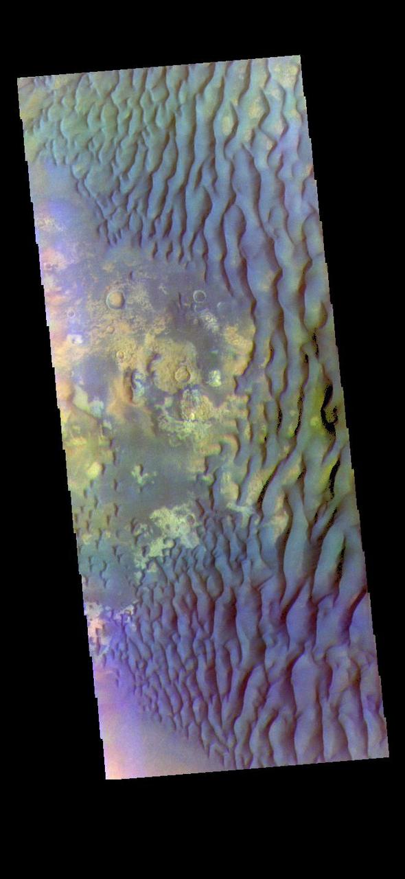
The THEMIS VIS camera contains 5 filters. The data from different filters can be combined in multiple ways to create a false color image. These false color images may reveal subtle variations of the surface not easily identified in a single band image. Today's false color image shows part of the floor of Kaiser Crater. Kaiser Crater is 207 km (129 miles) in diameter and is located in Noachis Terra west of Hellas Planitia. This sand dune field is one of several regions of sand dunes located on the southern part of the crater floor. The image also shows the complex crater floor beneath the dunes. These dunes are composed of basaltic sand that has collected in the bottom of the crater. The topographic depression of the crater forms a sand trap that prevents the sand from escaping. Dune fields are common in the bottoms of craters on Mars and appear as dark splotches that often lean up against the downwind walls of the craters. Dunes are useful for studying both the geology and meteorology of Mars. The sand forms by erosion of larger rocks, but it is unclear when and where this erosion took place on Mars or how such large volumes of sand could be formed. The dunes also indicate the local wind directions by their morphology. The THEMIS VIS camera is capable of capturing color images of the Martian surface using five different color filters. In this mode of operation, the spatial resolution and coverage of the image must be reduced to accommodate the additional data volume produced from using multiple filters. To make a color image, three of the five filter images (each in grayscale) are selected. Each is contrast enhanced and then converted to a red, green, or blue intensity image. These three images are then combined to produce a full color, single image. Because the THEMIS color filters don't span the full range of colors seen by the human eye, a color THEMIS image does not represent true color. Also, because each single-filter image is contrast enhanced before inclusion in the three-color image, the apparent color variation of the scene is exaggerated. Nevertheless, the color variation that does appear is representative of some change in color, however subtle, in the actual scene. Note that the long edges of THEMIS color images typically contain color artifacts that do not represent surface variation. Orbit Number: 91155 Latitude: -46.9827 Longitude: 19.3481 Instrument: VIS Captured: 2022-07-02 23:58 https://photojournal.jpl.nasa.gov/catalog/PIA26059
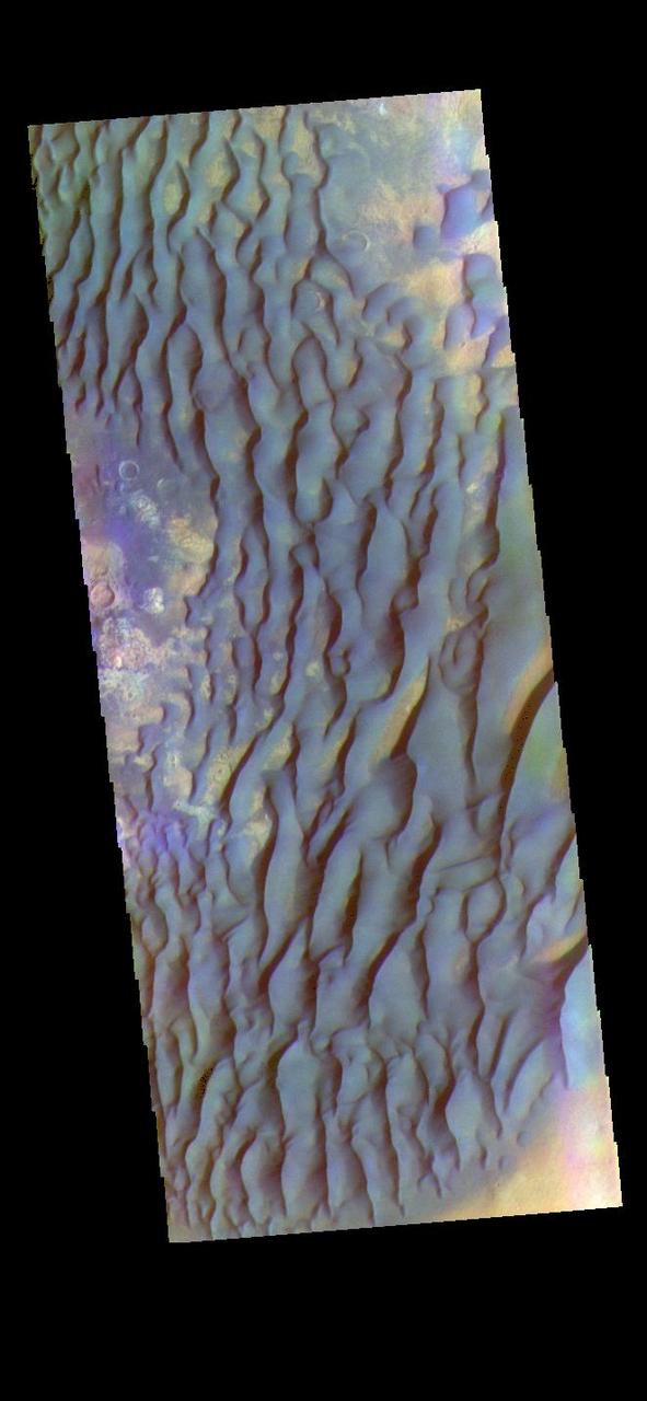
The THEMIS VIS camera contains 5 filters. The data from different filters can be combined in multiple ways to create a false color image. These false color images may reveal subtle variations of the surface not easily identified in a single band image. Today's false color image shows part of the floor of Kaiser Crater. Kaiser Crater is 207 km (129 miles) in diameter and is located in Noachis Terra west of Hellas Planitia. This sand dune field is one of several regions of sand dunes located on the southern part of the crater floor. The image also shows the complex crater floor beneath the dunes. These dunes are composed of basaltic sand that has collected in the bottom of the crater. The topographic depression of the crater forms a sand trap that prevents the sand from escaping. Dune fields are common in the bottoms of craters on Mars and appear as dark splotches that often lean up against the downwind walls of the craters. Dunes are useful for studying both the geology and meteorology of Mars. The sand forms by erosion of larger rocks, but it is unclear when and where this erosion took place on Mars or how such large volumes of sand could be formed. The dunes also indicate the local wind directions by their morphology. In this case, there are few clear slipfaces that would indicate the downwind direction. The crests of the dunes also typically run north-south in the image. This dune form indicates that there are probably two prevailing wind directions that run east and west (left to right and right to left). The THEMIS VIS camera is capable of capturing color images of the Martian surface using five different color filters. In this mode of operation, the spatial resolution and coverage of the image must be reduced to accommodate the additional data volume produced from using multiple filters. To make a color image, three of the five filter images (each in grayscale) are selected. Each is contrast enhanced and then converted to a red, green, or blue intensity image. These three images are then combined to produce a full color, single image. Because the THEMIS color filters don't span the full range of colors seen by the human eye, a color THEMIS image does not represent true color. Also, because each single-filter image is contrast enhanced before inclusion in the three-color image, the apparent color variation of the scene is exaggerated. Nevertheless, the color variation that does appear is representative of some change in color, however subtle, in the actual scene. Note that the long edges of THEMIS color images typically contain color artifacts that do not represent surface variation. Orbit Number: 91442 Latitude: -46.9777 Longitude: 19.5189 Instrument: VIS Captured: 2022-07-26 15:07 https://photojournal.jpl.nasa.gov/catalog/PIA26060
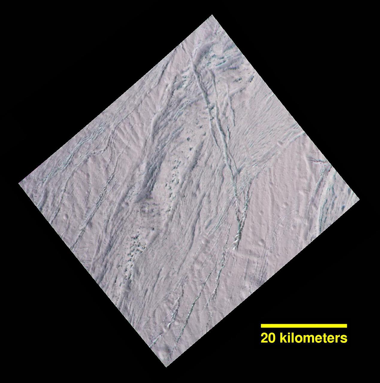
During its final close flyby of Saturn's moon Enceladus, NASA's Cassini spacecraft revisited a landscape, and a mystery, that it had originally glimpsed more than 10 years earlier. In views of this terrain captured during a 2005 flyby (see PIA06188), imaging scientists noticed small dark spots of an uncertain nature. Observing the same features in this false-color view, at higher resolution than before, provides some new insights. The spots are evidently large, relatively dark protrusions of solid "bedrock" ice and ice blocks scattered on and around the prominent ridge that runs across the scene from north to south (from top center toward lower left). The ice blocks range in size from dozens to hundreds of feet (tens to hundreds of meters). The false-color view uses an ultraviolet filter centered at 338 nanometers for blue, a green filter centered at 568 nanometers for green and a near-infrared filter centered at 930 nanometers for red -- thus covering a wider spectrum region than the human eye. As in earlier Cassini views of Enceladus using the same combination of color filters (see PIA06254), green-hued features represent coarse-grained or solid ice. Exposures of these kinds of ices are also found on the walls of cracks and troughs in this scene and elsewhere on Enceladus. To an observer on the surface, the prominent north-south trending ridge might look superficially like icy flatirons (tilted, triangular outcroppings of rock), but probably more shallowly dipping than terrestrial examples. The exposed line of ice blocks along its ridge crest might make it look a bit like a hogback (a narrow ridge with steep sides, often with vertical rocky outcrops along the top). On Enceladus, with no wind to scour loose particulate ice or "snow" off of them, the solid blocks are probably cleared by some combination of downslope movement of particulates, and perhaps sublimation. This image has a spatial scale of about 220 feet (67 meters) per pixel at its center, which is nearly twice the resolution of the earlier view (PIA06188). This terrain is on the moon's Saturn-facing side, a few degrees south of the equator. The view has been rotated so that north on Enceladus is up. The view was obtained by the Cassini spacecraft narrow-angle camera on Dec. 19, 2015. http://photojournal.jpl.nasa.gov/catalog/PIA20017
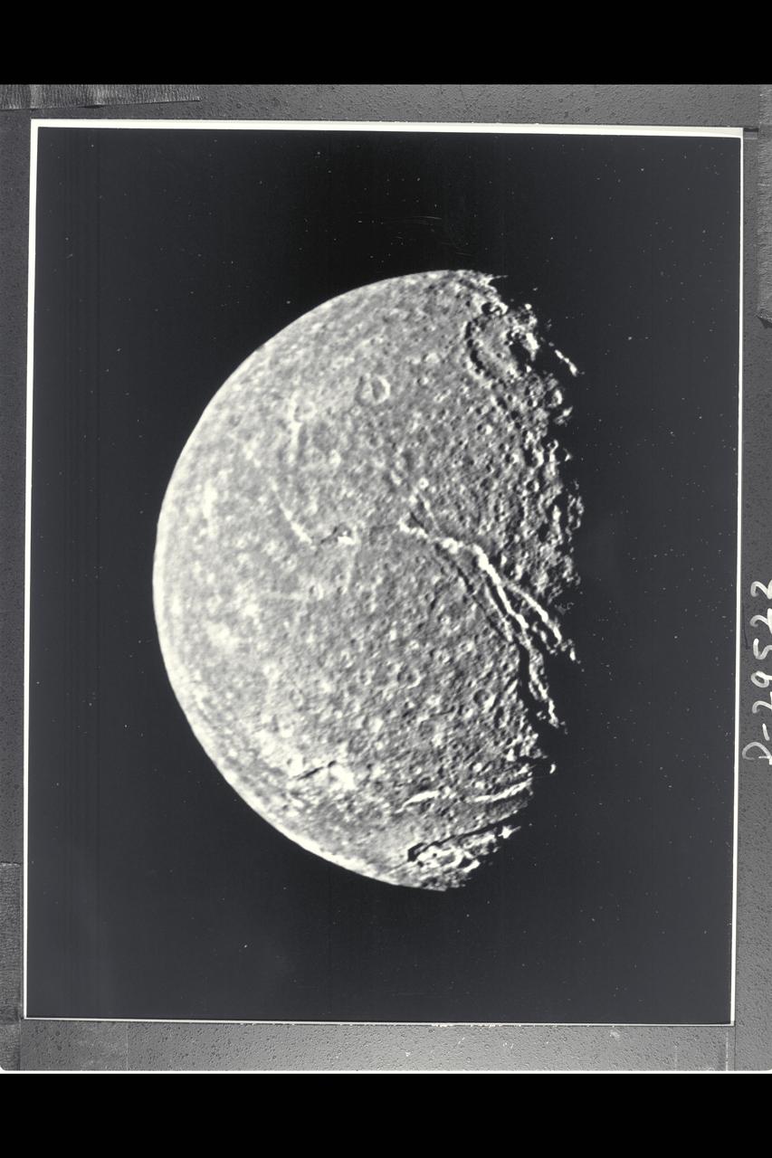
P-29522BW Range: 369,000 kilometers (229,000 miles) This is the highest-resolution picture of Titania returned by Voyager 2. The picture is a composite of two images taken through the clear-filter of Voyager's narrow-angle camera. The resolution of this image is 13 km (8 mi). Titania is the largest satellite of Uranus, with a diameter of little more than 1,600 km (1,000 mi). Abundant impact craters of many sizes pockmark the ancient surface. The most prominant features are fault valleys that stretch across Titania. They are up to 1,500 km (nearly 1,000 mi) long and as much as 75 km (45 mi) wide. In valleys seen at right center, the sunward-facing walls are very bright. While this is due partly to the lighting angle, the brightness also indicates the presence of a lighter material, possibly young frost deposits. An impact crater more than 200 km (125 mi) in diameter distinguishes the very bottom of the disk; the crater is cut by a younger fault valley more than 100 km (60 mi) wide. An even larger impact crater, perhaps 300 km (180 mi) across, is visible at top.
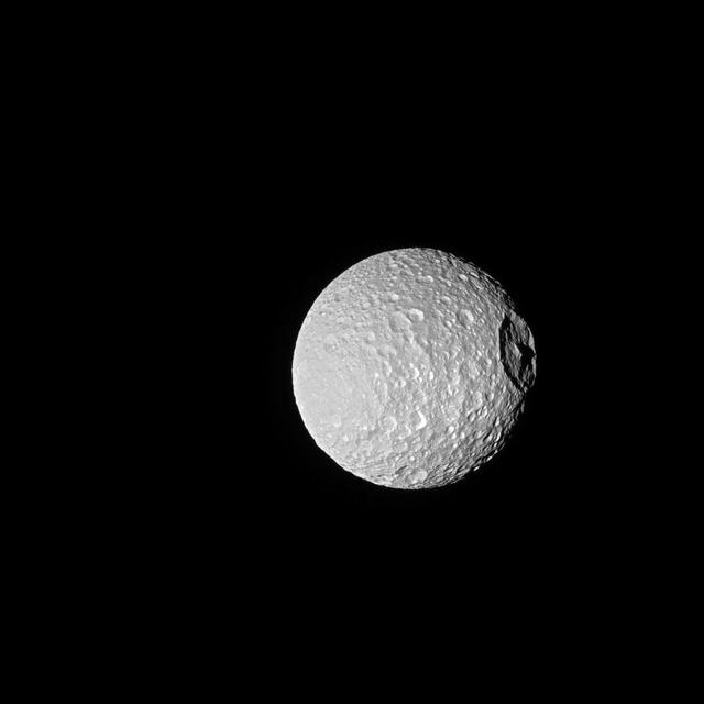
Shadows cast across Mimas' defining feature, Herschel Crater, provide an indication of the size of the crater's towering walls and central peak. Named after the icy moon's discoverer, astronomer William Herschel, the crater stretches 86 miles (139 kilometers) wide -- almost one-third of the diameter of Mimas (246 miles or 396 kilometers) itself. Large impact craters often have peaks in their center -- see Tethys' large crater Odysseus in PIA08400. Herschel's peak stands nearly as tall as Mount Everest on Earth. This view looks toward the anti-Saturn hemisphere of Mimas. North on Mimas is up and rotated 21 degrees to the left. The image was taken with the Cassini spacecraft narrow-angle camera on Oct. 22, 2016 using a combination of spectral filters which preferentially admits wavelengths of ultraviolet light centered at 338 nanometers. The view was acquired at a distance of approximately 115,000 miles (185,000 kilometers) from Mimas and at a Sun-Mimas-spacecraft, or phase, angle of 20 degrees. Image scale is 3,300 feet (1 kilometer) per pixel. http://photojournal.jpl.nasa.gov/catalog/PIA20515
The THEMIS VIS camera contains 5 filters. The data from different filters can be combined in multiple ways to create a false color image. These false color images may reveal subtle variations of the surface not easily identified in a single band image. Today's false color image shows sand dunes within Proctor Crater. These dunes are composed of basaltic sand that has collected in the bottom of the crater. The topographic depression of the crater forms a sand trap that prevents the sand from escaping. Dune fields are common in the bottoms of craters on Mars and appear as dark splotches that lean up against the downwind walls of the craters. Dunes are useful for studying both the geology and meteorology of Mars. The sand forms by erosion of larger rocks, but it is unclear when and where this erosion took place on Mars or how such large volumes of sand could be formed. The dunes also indicate the local wind directions by their morphology. In this case, there are few clear slipfaces that would indicate the downwind direction. The crests of the dunes also typically run north-south in the image. This dune form indicates that there are probably two prevailing wind directions that run east and west (left to right and right to left). Proctor Crater is located in Noachis Terra and is 172km (107miles) in diameter. Orbit Number: 83605 Latitude: -47.5325 Longitude: 30.3915 Instrument: VIS Captured: 2020-10-19 08:09 https://photojournal.jpl.nasa.gov/catalog/PIA24712
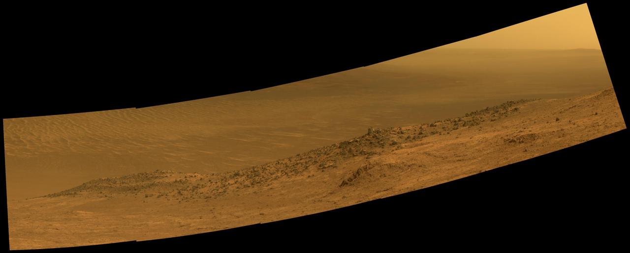
This scene from NASA's Mars Exploration Rover Opportunity shows "Wharton Ridge," which forms part of the southern wall of "Marathon Valley" on the western rim of Endeavour Crater. The full extent of Wharton Ridge is visible, with the floor of Endeavour Crater beyond it and the far wall of the crater in the distant background. Near the right edge of the scene is "Lewis and Clark Gap," through which Opportunity crossed from Marathon Valley to "Bitterroot Valley" in September 2016. Before the rover departed Marathon Valley, its panoramic camera (Pancam) acquired the component images for this scene on Aug. 30, 2016, during the 4,480th Martian day, or sol, of Opportunity's work on Mars. Opportunity's science team chose the ridge's name to honor the memory of Robert A. Wharton (1951-2012), an astrobiologist who was a pioneer in the use of terrestrial analog environments, particularly in Antarctica, to study scientific problems connected to the habitability of Mars. Over the course of his career, he was a visiting senior scientist at NASA Headquarters, vice president for research at the Desert Research Institute, provost at Idaho State University, and president of the South Dakota School of Mines and Technology. The view spans from east-northeast at left to southeast at right. It merges exposures taken through three of the Pancam's color filters, centered on wavelengths of 753 nanometers (near-infrared), 535 nanometers (green) and 432 nanometers (violet). It is presented in approximately true color. http://photojournal.jpl.nasa.gov/catalog/PIA20849
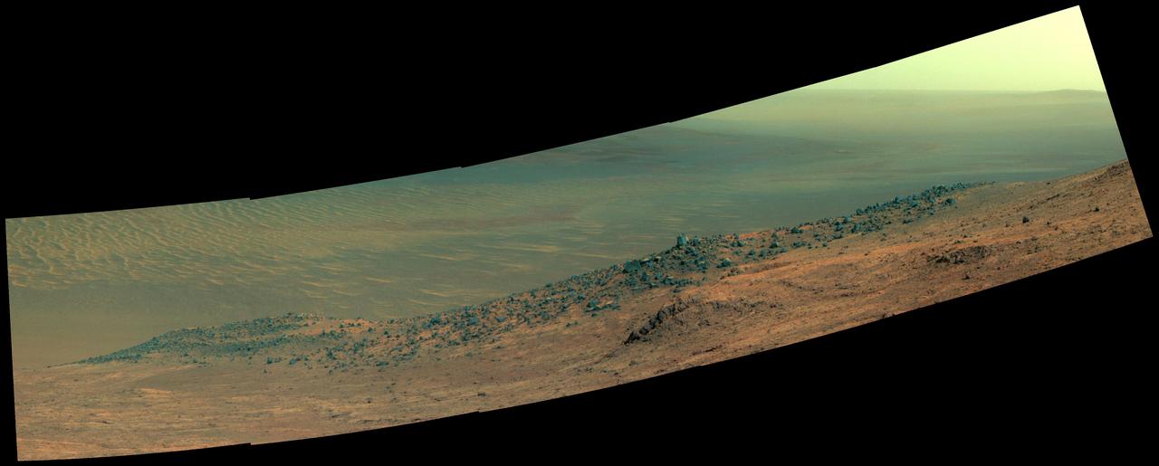
This scene from NASA's Mars Exploration Rover Opportunity shows "Wharton Ridge," which forms part of the southern wall of "Marathon Valley" on the western rim of Endeavour Crater. In this version of the scene the landscape is presented in enhanced color to make differences in surface materials more easily visible The full extent of Wharton Ridge is visible, with the floor of Endeavour Crater beyond it and the far wall of the crater in the distant background. Near the right edge of the scene is "Lewis and Clark Gap," through which Opportunity crossed from Marathon Valley to "Bitterroot Valley" in September 2016. Before the rover departed Marathon Valley, its panoramic camera (Pancam) acquired the component images for this scene on Aug. 30, 2016, during the 4,480th Martian day, or sol, of Opportunity's work on Mars. Opportunity's science team chose the ridge's name to honor the memory of Robert A. Wharton (1951-2012), an astrobiologist who was a pioneer in the use of terrestrial analog environments, particularly in Antarctica, to study scientific problems connected to the habitability of Mars. Over the course of his career, he was a visiting senior scientist at NASA Headquarters, vice president for research at the Desert Research Institute, provost at Idaho State University, and president of the South Dakota School of Mines and Technology. The view spans from east-northeast at left to southeast at right. Color in the scene comes from component images taken through three of the Pancam's color filters, centered on wavelengths of 753 nanometers (near-infrared), 535 nanometers (green) and 432 nanometers (violet). http://photojournal.jpl.nasa.gov/catalog/PIA20850
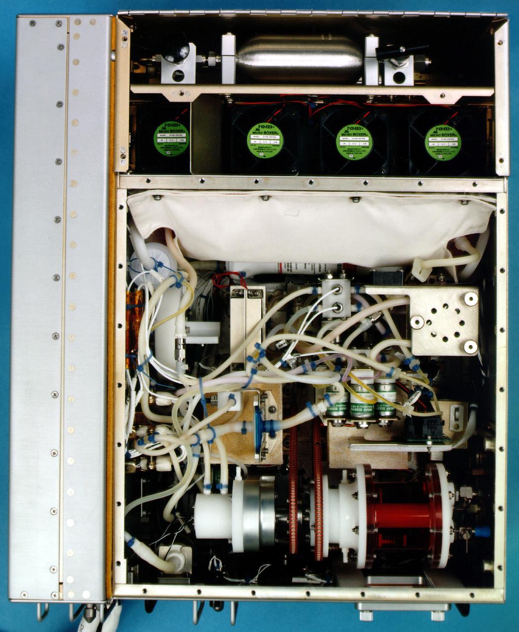
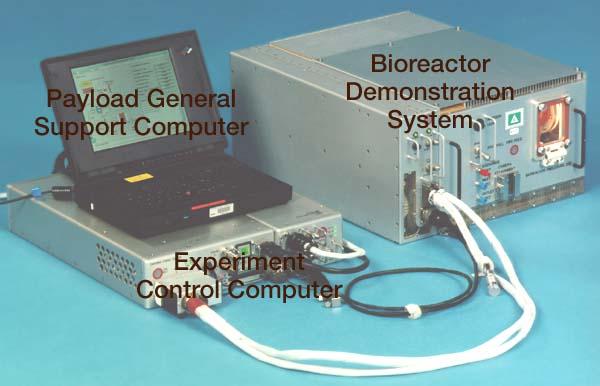
Bioreactor Demonstration System (BDS) comprises an electronics module, a gas supply module, and the incubator module housing the rotating wall vessel and its support systems. Nutrient media are pumped through an oxygenator and the culture vessel. The shell rotates at 0.5 rpm while the irner filter typically rotates at 11.5 rpm to produce a gentle flow that ensures removal of waste products as fresh media are infused. Periodically, some spent media are pumped into a waste bag and replaced by fresh media. When the waste bag is filled, an astronaut drains the waste bag and refills the supply bag through ports on the face of the incubator. Pinch valves and a perfusion pump ensure that no media are exposed to moving parts. An Experiment Control Computer controls the Bioreactor, records conditions, and alerts the crew when problems occur. The crew operates the system through a laptop computer displaying graphics designed for easy crew training and operation. The work is sponsored by NASA's Office of Biological and Physical Research. The bioreactor is managed by the Biotechnology Cell Science Program at NASA's Johnson Space Center (JSC). NASA-sponsored bioreactor research has been instrumental in helping scientists to better understand normal and cancerous tissue development. In cooperation with the medical community, the bioreactor design is being used to prepare better models of human colon, prostate, breast and ovarian tumors. Cartilage, bone marrow, heart muscle, skeletal muscle, pancreatic islet cells, liver and kidney are just a few of the normal tissues being cultured in rotating bioreactors by investigators. See No. 0101825 for a version with major elements labeled, and No. 0103180 for an operational schematic. 0101816
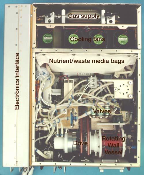
Bioreactor Demonstration System (BDS) comprises an electronics module, a gas supply module, and the incubator module housing the rotating wall vessel and its support systems. Nutrient media are pumped through an oxygenator and the culture vessel. The shell rotates at 0.5 rpm while the irner filter typically rotates at 11.5 rpm to produce a gentle flow that ensures removal of waste products as fresh media are infused. Periodically, some spent media are pumped into a waste bag and replaced by fresh media. When the waste bag is filled, an astronaut drains the waste bag and refills the supply bag through ports on the face of the incubator. Pinch valves and a perfusion pump ensure that no media are exposed to moving parts. An Experiment Control Computer controls the Bioreactor, records conditions, and alerts the crew when problems occur. The crew operates the system through a laptop computer displaying graphics designed for easy crew training and operation. The work is sponsored by NASA's Office of Biological and Physical Research. The bioreactor is managed by the Biotechnology Cell Science Program at NASA's Johnson Space Center (JSC). NASA-sponsored bioreactor research has been instrumental in helping scientists to better understand normal and cancerous tissue development. In cooperation with the medical community, the bioreactor design is being used to prepare better models of human colon, prostate, breast and ovarian tumors. Cartilage, bone marrow, heart muscle, skeletal muscle, pancreatic islet cells, liver and kidney are just a few of the normal tissues being cultured in rotating bioreactors by investigators. See No. 0101816 for a version without labels, and No. 0103180 for an operational schematic.
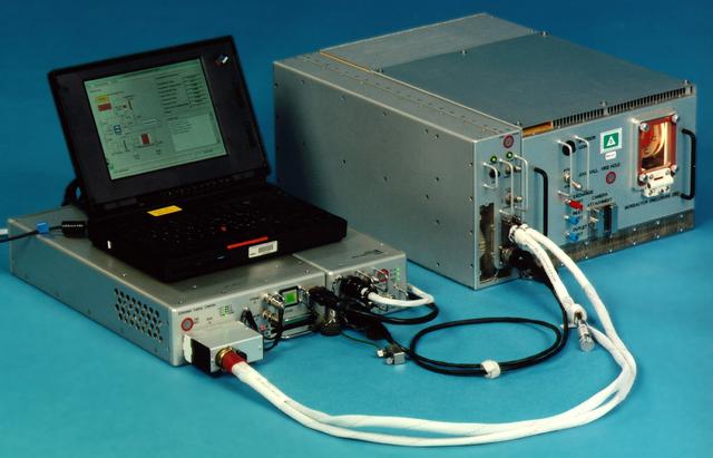
Bioreactor Demonstration System (BDS) comprises an electronics module, a gas supply module, and the incubator module housing the rotating wall vessel and its support systems. Nutrient media are pumped through an oxygenator and the culture vessel. The shell rotates at 0.5 rpm while the irner filter typically rotates at 11.5 rpm to produce a gentle flow that ensures removal of waste products as fresh media are infused. Periodically, some spent media are pumped into a waste bag and replaced by fresh media. When the waste bag is filled, an astronaut drains the waste bag and refills the supply bag through ports on the face of the incubator. Pinch valves and a perfusion pump ensure that no media are exposed to moving parts. An Experiment Control Computer controls the Bioreactor, records conditions, and alerts the crew when problems occur. The crew operates the system through a laptop computer displaying graphics designed for easy crew training and operation. The work is sponsored by NASA's Office of Biological and Physical Research. The bioreactor is managed by the Biotechnology Cell Science Program at NASA's Johnson Space Center (JSC). NASA-sponsored bioreactor research has been instrumental in helping scientists to better understand normal and cancerous tissue development. In cooperation with the medical community, the bioreactor design is being used to prepare better models of human colon, prostate, breast and ovarian tumors. Cartilage, bone marrow, heart muscle, skeletal muscle, pancreatic islet cells, liver and kidney are just a few of the normal tissues being cultured in rotating bioreactors by investigators. See No. 0101824 for a version with labels, and No. 0103180 for an operational schematic.
Bioreactor Demonstration System (BDS) comprises an electronics module, a gas supply module, and the incubator module housing the rotating wall vessel and its support systems. Nutrient media are pumped through an oxygenator and the culture vessel. The shell rotates at 0.5 rpm while the irner filter typically rotates at 11.5 rpm to produce a gentle flow that ensures removal of waste products as fresh media are infused. Periodically, some spent media are pumped into a waste bag and replaced by fresh media. When the waste bag is filled, an astronaut drains the waste bag and refills the supply bag through ports on the face of the incubator. Pinch valves and a perfusion pump ensure that no media are exposed to moving parts. An Experiment Control Computer controls the Bioreactor, records conditions, and alerts the crew when problems occur. The crew operates the system through a laptop computer displaying graphics designed for easy crew training and operation. The work is sponsored by NASA's Office of Biological and Physical Research. The bioreactor is managed by the Biotechnology Cell Science Program at NASA's Johnson Space Center (JSC). NASA-sponsored bioreactor research has been instrumental in helping scientists to better understand normal and cancerous tissue development. In cooperation with the medical community, the bioreactor design is being used to prepare better models of human colon, prostate, breast and ovarian tumors. Cartilage, bone marrow, heart muscle, skeletal muscle, pancreatic islet cells, liver and kidney are just a few of the normal tissues being cultured in rotating bioreactors by investigators. See No. 0101823 for a version without labels, and No. 0103180 for an operational schematic.

This sturning image, taken by the newly installed Advanced Camera for Surveys (ACS) aboard the Hubble Space Telescope (HST), is an image of the center of the Omega Nebula. It is a hotbed of newly born stars wrapped in colorful blankets of glowing gas and cradled in an enormous cold, dark hydrogen cloud. The region of nebula shown in this photograph is about 3,500 times wider than our solar system. The nebula, also called M17 and the Swan Nebula, resides 5,500 light-years away in the constellation Sagittarius. The Swan Nebula is illuminated by ultraviolet radiation from young, massive stars, located just beyond the upper-right corner of the image. The powerful radiation from these stars evaporates and erodes the dense cloud of cold gas within which the stars formed. The blistered walls of the hollow cloud shine primarily in the blue, green, and red light emitted by excited atoms of hydrogen, nitrogen, oxygen, and sulfur. Particularly striking is the rose-like feature, seen to the right of center, which glows in the red light emitted by hydrogen and sulfur. As the infant stars evaporate the surrounding cloud, they expose dense pockets of gas that may contain developing stars. One isolated pocket is seen at the center of the brightest region of the nebula. Other dense pockets of gas have formed the remarkable feature jutting inward from the left edge of the image. The color image is constructed from four separate images taken in these filters: blue, near infrared, hydrogen alpha, and doubly ionized oxygen. Credit: NASA, H. Ford (JHU), G. Illingworth (USCS/LO), M. Clampin (STScI), G. Hartig (STScI), the ACS Science Team, and ESA.

This NASA Hubble Space Telescope image, taken in near-infrared light, transforms the pillars into eerie, wispy silhouettes, which are seen against a background of myriad stars. The near-infrared light can penetrate much of the gas and dust, revealing stars behind the nebula as well as hidden away inside the pillars. Some of the gas and dust clouds are so dense that even the near-infrared light cannot penetrate them. New stars embedded in the tops of the pillars, however, are apparent as bright sources that are unseen in the visible image. The ghostly bluish haze around the dense edges of the pillars is material getting heated up by the intense ultraviolet radiation from a cluster of young, massive stars and evaporating away into space. The stellar grouping is above the pillars and cannot be seen in the image. At the top edge of the left-hand pillar, a gaseous fragment has been heated up and is flying away from the structure, underscoring the violent nature of star-forming regions. Astronomers used filters that isolate the light from newly formed stars, which are invisible in the visible-light image. At these wavelengths, astronomers are seeing through the pillars and even through the back wall of the nebula cavity and can see the next generations of stars just as they're starting to emerge from their formative nursery. Credit: NASA, ESA, and the Hubble Heritage Team (STScI/AURA) Read more: <a href="http://1.usa.gov/1HGfkqr" rel="nofollow">1.usa.gov/1HGfkqr</a> <b><a href="http://www.nasa.gov/audience/formedia/features/MP_Photo_Guidelines.html" rel="nofollow">NASA image use policy.</a></b> <b><a href="http://www.nasa.gov/centers/goddard/home/index.html" rel="nofollow">NASA Goddard Space Flight Center</a></b> enables NASA’s mission through four scientific endeavors: Earth Science, Heliophysics, Solar System Exploration, and Astrophysics. Goddard plays a leading role in NASA’s accomplishments by contributing compelling scientific knowledge to advance the Agency’s mission. <b>Follow us on <a href="http://twitter.com/NASAGoddardPix" rel="nofollow">Twitter</a></b> <b>Like us on <a href="http://www.facebook.com/pages/Greenbelt-MD/NASA-Goddard/395013845897?ref=tsd" rel="nofollow">Facebook</a></b> <b>Find us on <a href="http://instagrid.me/nasagoddard/?vm=grid" rel="nofollow">Instagram</a></b>
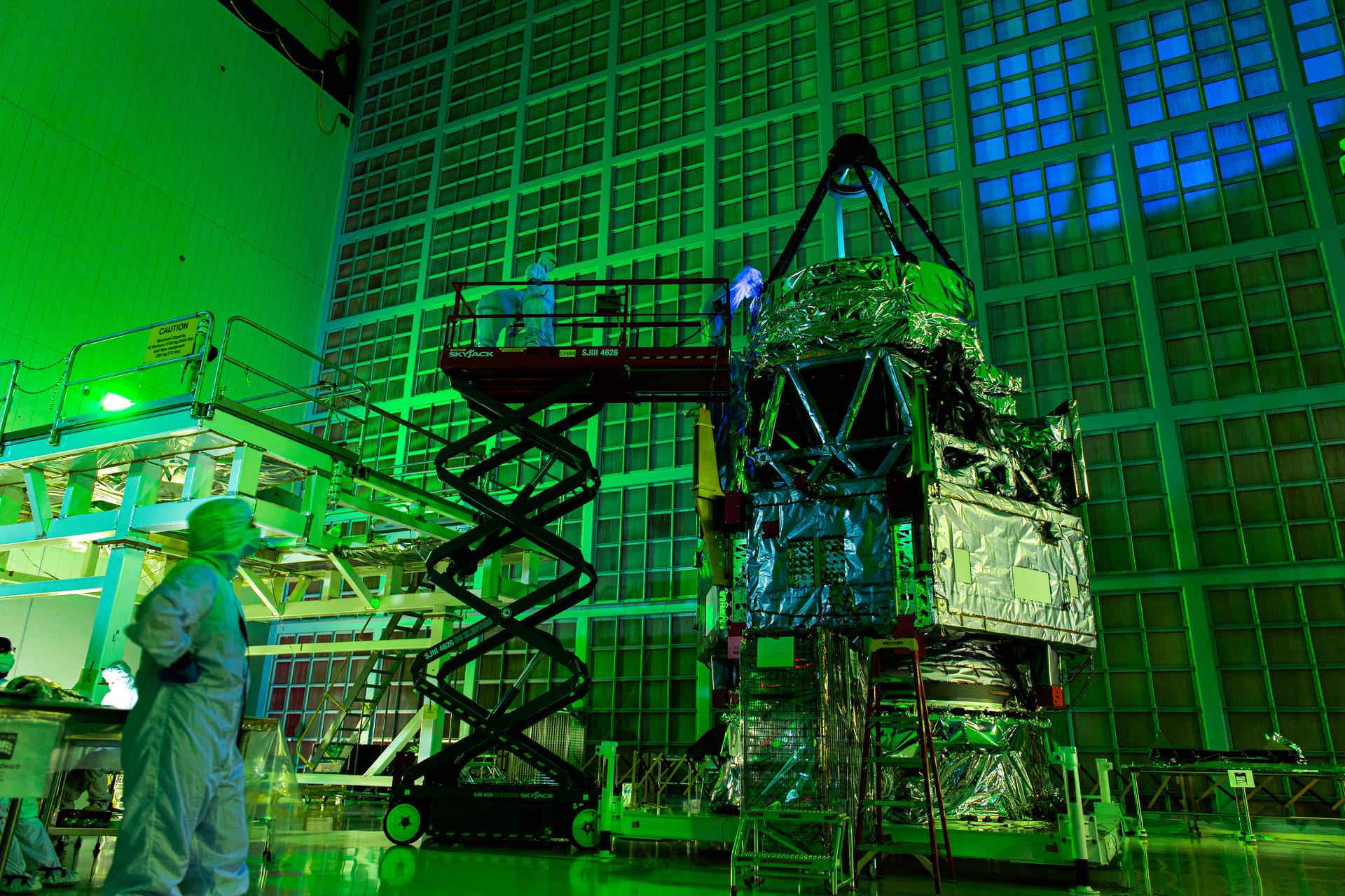
Roman Space Telescope team members inspect the primary mirror in the dark using flashlights and UV lights to help them see any contamination, inside the cleanroom at Goddard Space Flight Center, Greenbelt Md., July 2, 2025. The green glow of the room is due to a long exposure time, the green comes from a light on the left wall which indicates optimal airflow through the room. This photo has been approved for public release. NASA/Mike Guinto