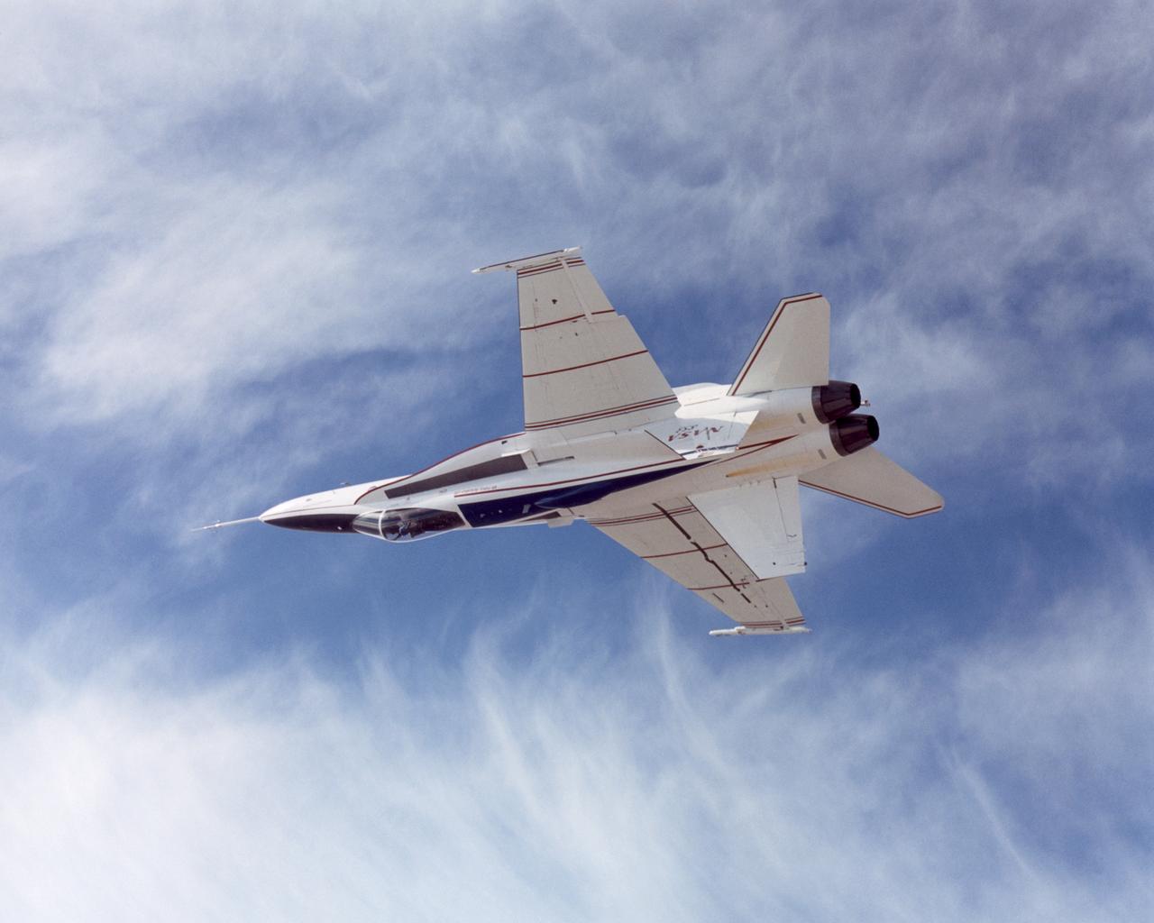
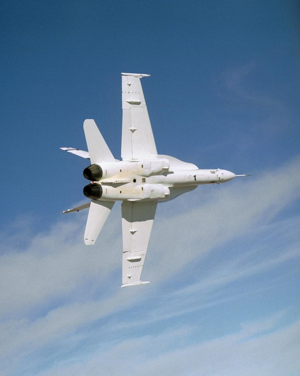
NASA's Active Aeroelastic Wing F/A-18A research aircraft rolls upside down during a 360-degree aileron roll on a test mission.
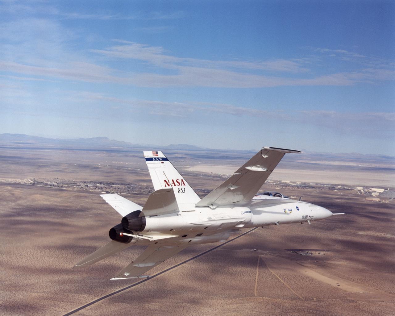
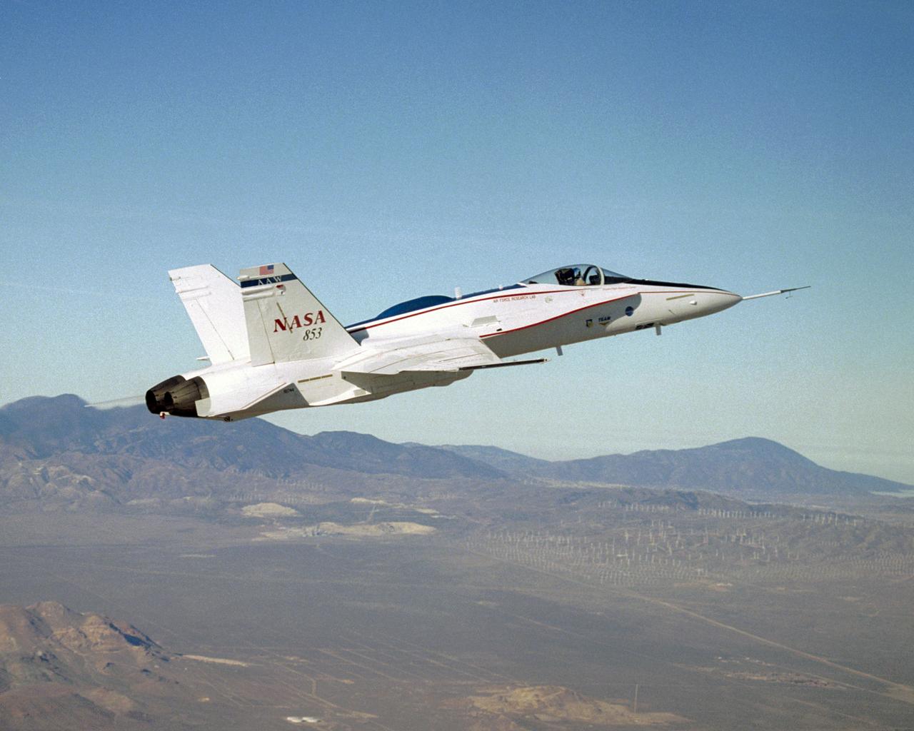
NASA 853, a modified former Navy F/A-18A fighter plane, is now performing research duties in the Active Aeroelastic Wing project at NASA Dryden Flight Research Center, Edwards AFB, California.
NASA Dryden's highly-modified Active Aeroelastic Wing F/A-18A shows off its form during a 360-degree aileron roll during a research flight.
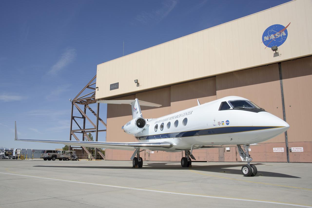
NASA’s Subsonic Research Aircraft Testbed, or SCRAT, is a modified Gulfstream III that operates out of Armstrong Flight Research Center in Edwards, California. SCRAT the test bed aircraft for the ACTE flexible-flap research project, which examines flexible wing flap technology’s benefits to aerodynamic efficiency.
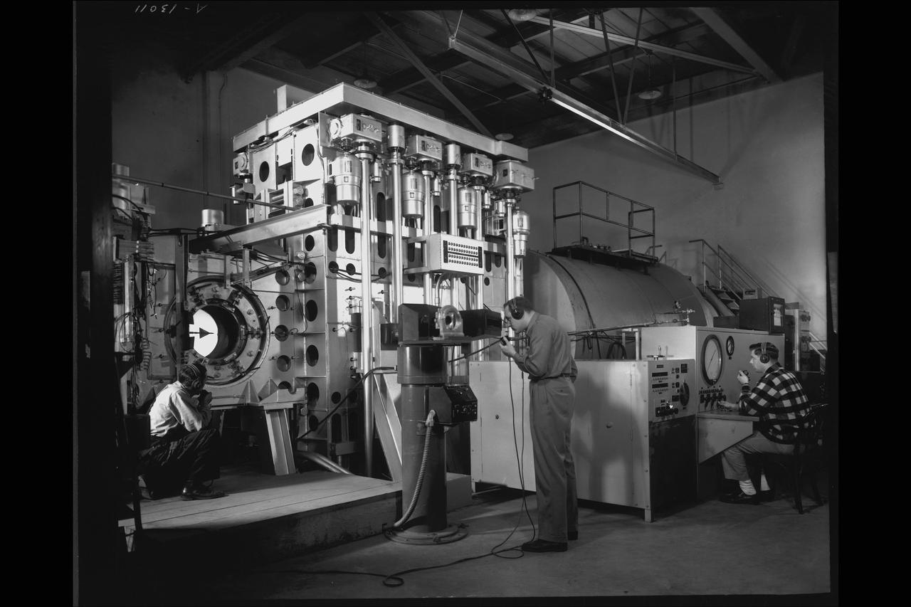
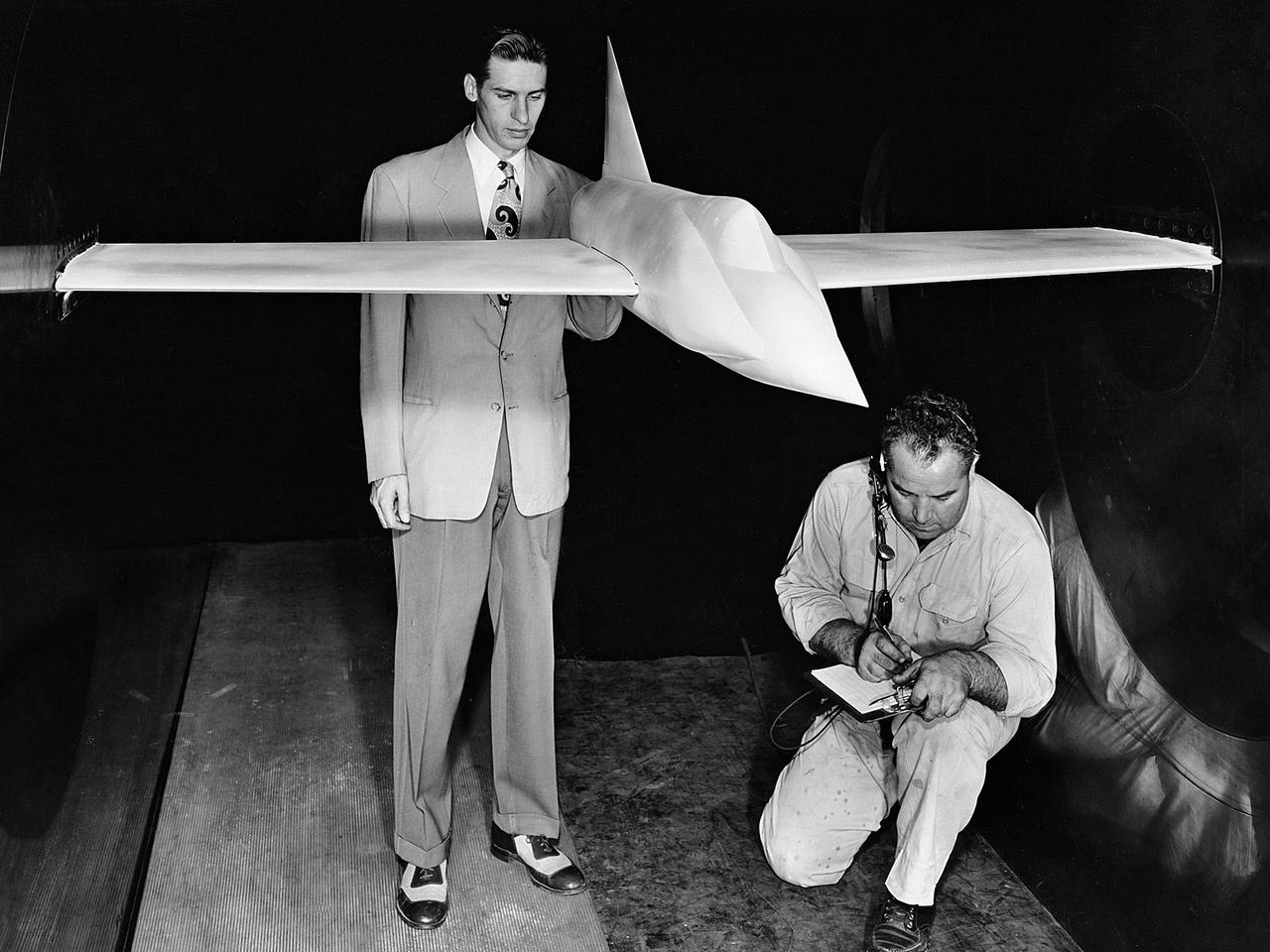
NACA Photographer NASA Ames 1X3Ft W.T Blowdown, flexible throat: A swept wing model readied for a test in June 1948, in the 1 by 3 foot blowdown tunnel with a variable geometry throat mechanism
Long, thin, high-aspect-ratio wings are considered crucial to the design of future long-range aircraft, including fuel-efficient airliners and cargo transports. Unlike the short, stiff wings found on most aircraft today, slender, flexible airfoils are susceptible to uncontrollable vibrations, known as flutter, and may be stressed by bending forces from wind gusts and atmospheric turbulence. To improve ride quality, efficiency, safety, and the long-term health of flexible aircraft structures, NASA is using the X-56A Multi-Utility Technology Testbed (MUTT) to investigate key technologies for active flutter suppression and gust-load alleviation.
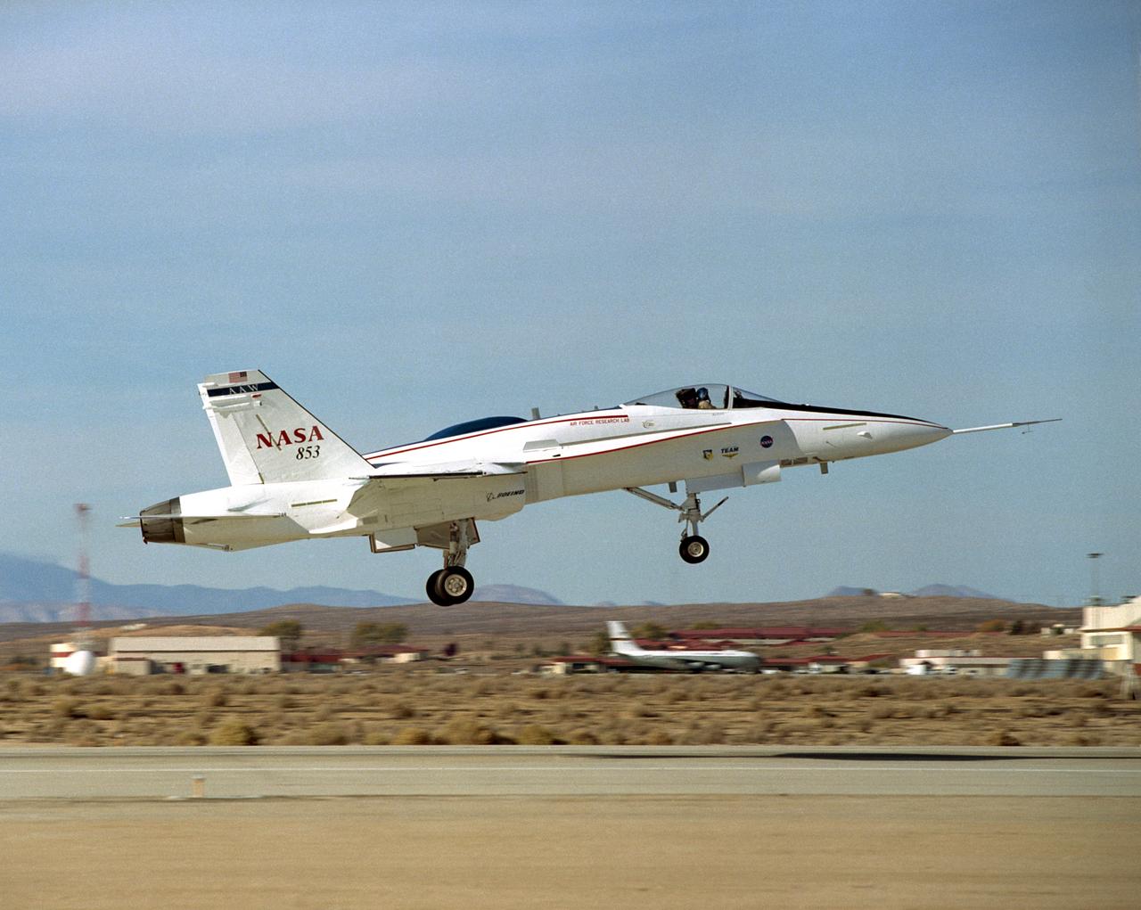
The Active Aeroelastic Wing F-18A lifts off on its first checkout flight November 15, 2002, from NASA's Dryden Flight Research Center at Edwards Air Force Base, Calif. The checkout flight initiated a two-phase NASA--Air Force flight research program that will investigate the potential of aerodynamically twisting flexible wings to improve maneuverability of high-performance aircraft at transonic and supersonic speeds.
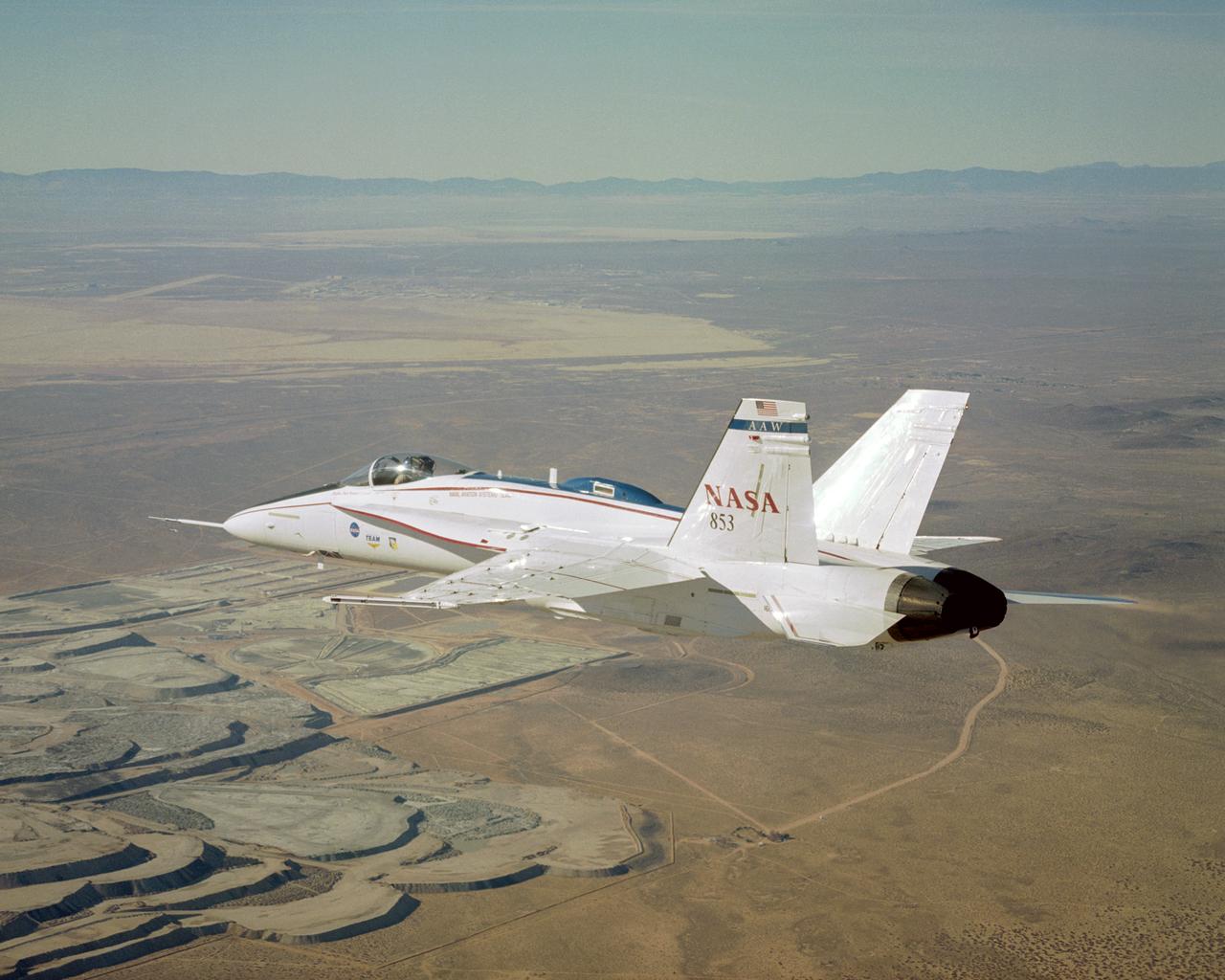
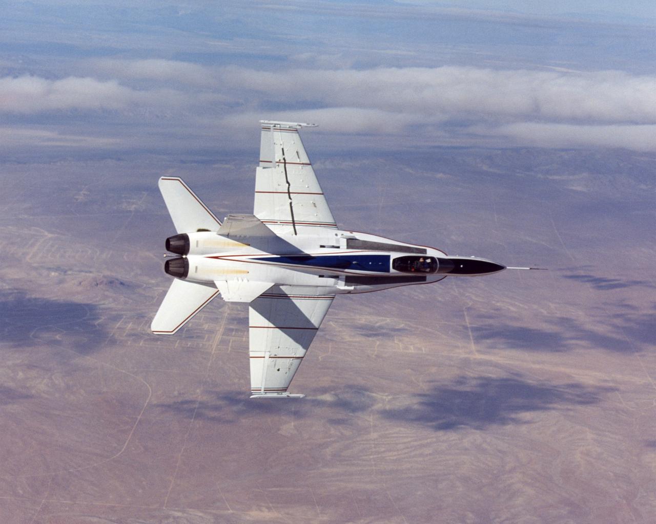
NASA's modified Active Aeroelastic Wing F/A-18 skims over portions of the U.S. Borax mine during a recent mission from the Dryden Flight Research Center.
NASA's Active Aeroelastic Wing F/A-18 rolls into a hard left turn during a research flight in early December 2004 from the Dryden Flight Research Center.
NASA's Active Aeroelastic Wing F/A-18 resumed flight tests in the second phase of the program at the Dryden Flight Research Center in early December 2004.
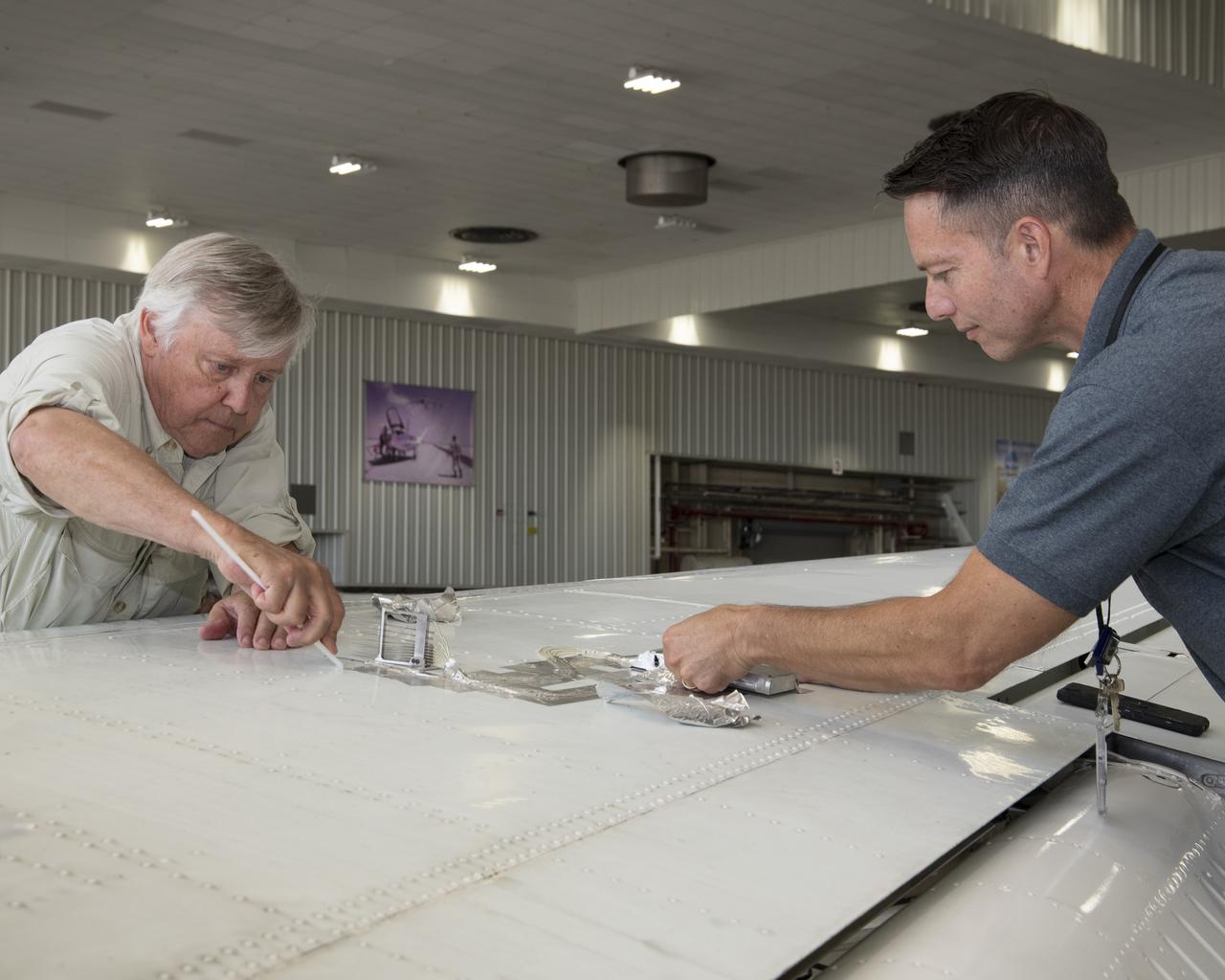
Cal Poly San Luis Obispo Professor Russ Westphal, left, and NASA Armstrong’s Technology Transfer Officer Benjamin Tomlinson remove the Boundary Layer Data System (BLDS) sensor attached to the wing of a Beechcraft Beech 200 Super King Air. The BLDS was flight tested at NASA’s Armstrong Flight Research Center to showcase rapid and flexible flight-testing capabilities.
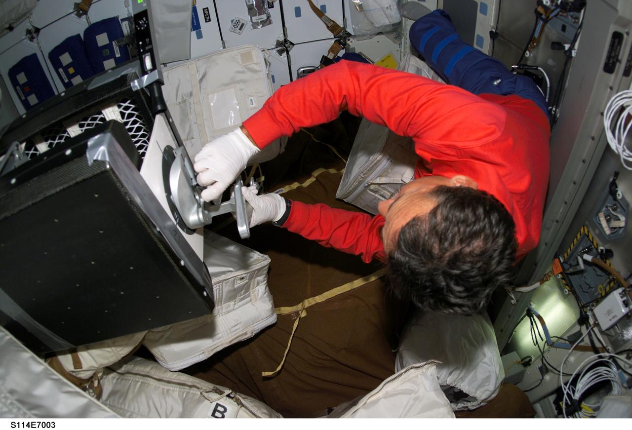
S114-E-7003 (4 August 2005) --- Astronaut Charles J. Camarda, STS-114 mission specialist, performs a middeck evaluation of the mechanical "plug" option for Reinforced Carbon-Carbon (RCC) repair aboard the Space Shuttle Discovery. Camarda used special pre-designated tools to accomplish the procedure, along with round thin, flexible 7-inch-diamter carbon-silicon cover plates designed to flex up to 0.25 inch to conform to the wing leading edge RCC panels, a hardware attachment mechanism similar to a toggle bolt and sealant.
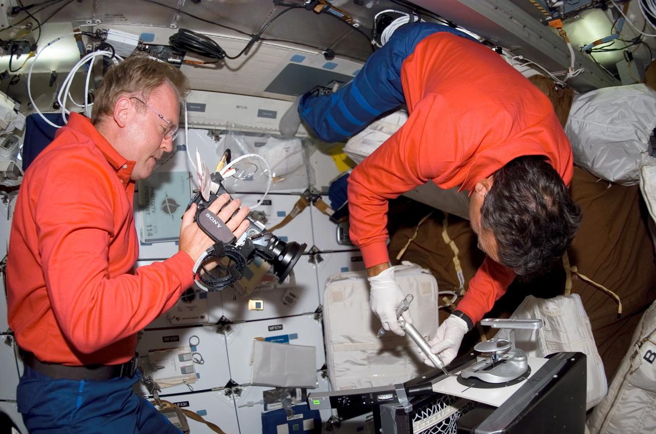
S114-E-7001 (4 August 2005) --- Astronaut Andrew S. W. Thomas, STS-114 mission specialist, photographs a middeck evaluation of the mechanical "plug" option for Reinforced Carbon-Carbon (RCC) repair aboard the Space Shuttle Discovery. Astronaut Charles J. Camarda, mission specialist, uses special pre-designated tools to accomplish the procedure, along with round thin, flexible 7-inch-diamter carbon-silicon cover plates designed to flex up to 0.25 inch to conform to the wing leading edge RCC panels, a hardware attachment mechanism similar to a toggle bolt and sealant.
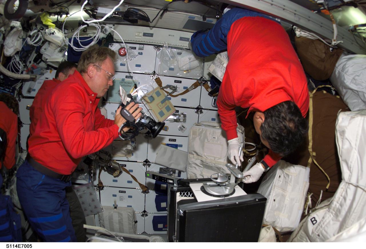
S114-E-7005 (4 August 2005) --- Astronaut Andrew S. W. Thomas, STS-114 mission specialist, photographs a middeck evaluation of the mechanical "plug" option for Reinforced Carbon-Carbon (RCC) repair aboard the Space Shuttle Discovery. Astronaut Charles J. Camarda, mission specialist, uses special pre-designated tools to accomplish the procedure, along with round thin, flexible 7-inch-diamter carbon-silicon cover plates designed to flex up to 0.25 inch to conform to the wing leading edge RCC panels, a hardware attachment mechanism similar to a toggle bolt and sealant.
A .10-scale model of Convair’s XF-102 in the 8- by 6-Foot Supersonic Wind Tunnel at the National Advisory Committee for Aeronautics (NACA) Lewis Flight Propulsion Laboratory for jet exit studies. The XF-102 was a prototype of the F-102 Delta Dagger. The F-102 served as an interceptor against long range bombers from the Soviet Union. The aircraft was powered by a Pratt and Whitney J57 turbojet. The first prototype crashed two weeks after is first flight on October 24, 1953, just months after this photograph. Engineers then incorporated the fixed-wing design to reduce drag at supersonic speeds. The production model F-102 became the first delta-wing supersonic aircraft in operation. The 8- by 6-Foot Supersonic Wind Tunnel is used to study propulsion systems, including inlets and exit nozzles, combustion fuel injectors, flame holders, exit nozzles, and controls on ramjet and turbojet engines. Flexible sidewalls alter the tunnel’s nozzle shape to vary the Mach number during operation. A seven-stage axial compressor, driven by three electric motors that yield a total of 87,000 horsepower, generates air speeds from Mach 0.36 to 2.0.