The Space Shuttle Main Engine (SSME) reached a historic milestone July 16, 2004, when a successful flight acceptance test was conducted at NASA Stennis Space Center (SSC). The engine tested today is the first complete engine to be tested and shipped in its entirety to Kennedy Space Center for installation on Space Shuttle Discovery for STS-114, NASA's Return to Flight mission. The engine test, which began about 3:59 p.m. CDT, ran for 520 seconds (8 minutes), the length of time it takes for the Space Shuttle to reach orbit.
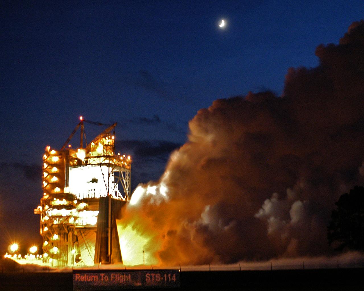
The Space Shuttle's Main Engine (SSME) reached another milestone Aug. 19, 2004, when a successful flight acceptance test was conducted at NASA Stennis Space Center (SSC). The engine tested was the final of three engines that will carry the next Space Shuttle into orbit. The engine will be shipped to NASA Kennedy Space Center in Florida for installation on Space Shuttle Discovery for STS-114, NASA's Return to Flight mission. The engine test, which began about 8:10 p.m. CDT, ran for 520 seconds (8 minutes), the length of time it takes for the Space Shuttle to reach orbit.
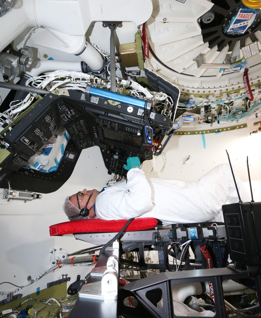
Inside Boeing's Commercial Crew and Cargo Processing Facility at NASA's Kennedy Space Center in Florida, NASA astronaut Eric Boe participates in the first full-up acceptance test of Boeing's CST-100 Starliner, on Aug. 22, 2018. The Starliner will be the first to fly astronauts on the company's Crew Flight Test (CFT), following environmental testing in El Segundo, California. Acceptance testing is a critical part of the spacecraft build progression. Generally, it gives the crew module a clean bill of health that it is built correctly, performs to expectations and is ready to fly.
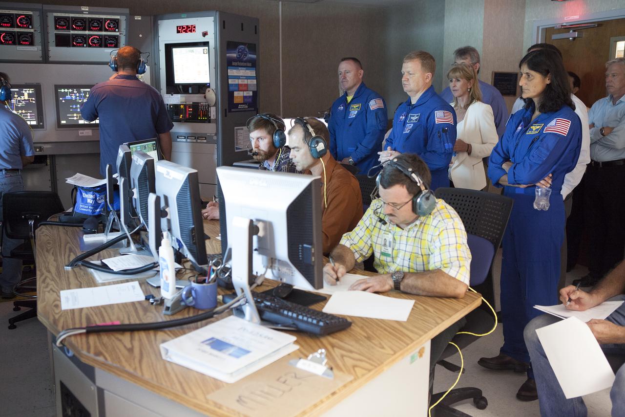
NASA astronauts Barry "Butch" Wilmore, from left, Eric Boe and Suni Williams watch as Aerojet Rocketdyne test team engineers direct the test-firing of an RL10 engine at the company's facility in West Palm Beach, Florida. The engine will be one of two used for the Centaur upper stage during a United Launch Alliance Atlas V mission to launch Boeing's CST-100 Starliner on a flight test carrying a crew. The engine was test-fired as part of acceptance testing to confirm the engine is ready for flight.
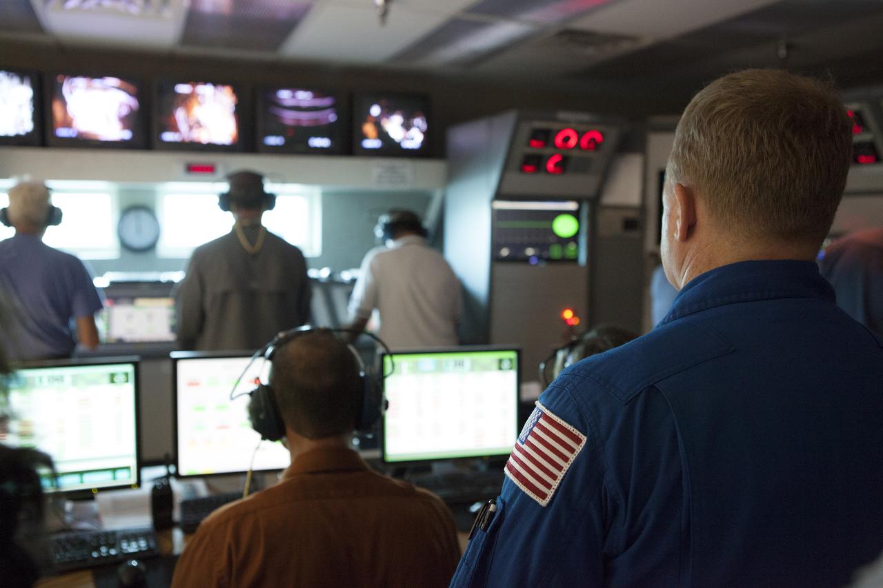
NASA astronaut Eric Boe watches as Aerojet Rocketdyne test team engineers direct the test-firing of an RL10 engine at the company's facility in West Palm Beach, Florida. The engine will be one of two used for the Centaur upper stage during a United Launch Alliance Atlas V mission to launch Boeing's CST-100 Starliner on a flight test carrying a crew. The engine was test-fired as part of acceptance testing to confirm the engine is ready for flight.
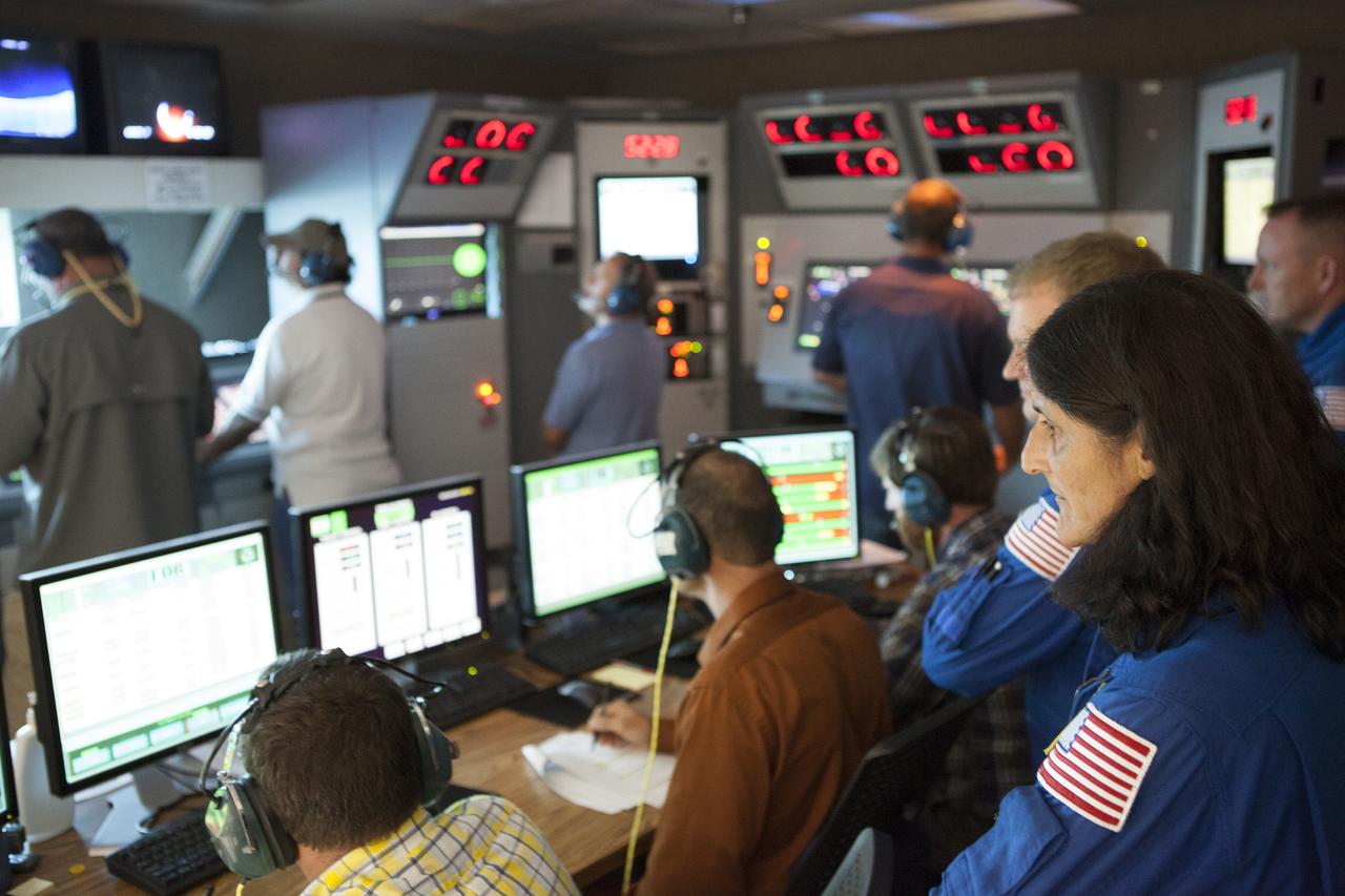
NASA astronaut Suni Williams watches as Aerojet Rocketdyne test team engineers direct the test-firing of an RL10 engine at the company's facility in West Palm Beach, Florida. The engine will be one of two used for the Centaur upper stage during a United Launch Alliance Atlas V mission to launch Boeing's CST-100 Starliner on a flight test carrying a crew. The engine was test-fired as part of acceptance testing to confirm the engine is ready for flight.

An RL10 engine stands in a vacuum chamber at Aerojet Rocketdyne's test stand in West Palm Beach, Florida. The engine will be one of two used for the Centaur upper stage during a United Launch Alliance Atlas V mission to launch Boeing's CST-100 Starliner on a flight test carrying a crew. The engine was test-fired as part of acceptance testing to confirm the engine is ready for flight.
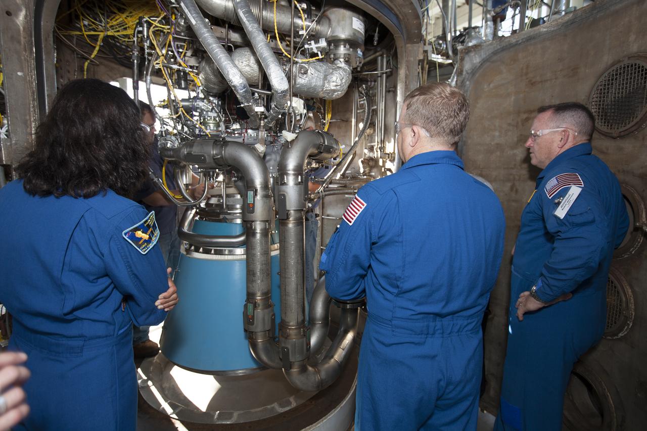
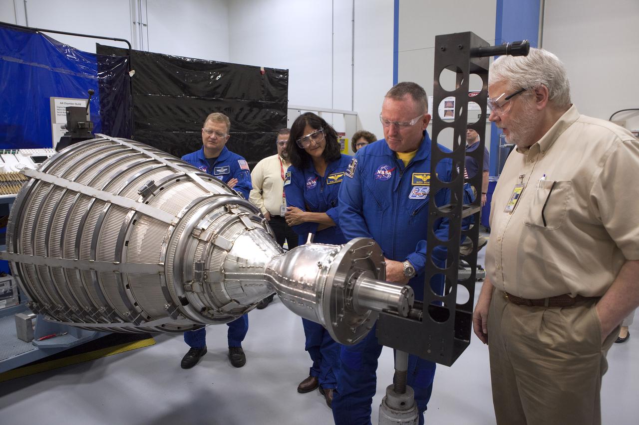
NASA astronauts Suni Williams, from left, Eric Boe and Barry "Butch" Wilmore survey an RL10 engine as it stands in a vacuum chamber at Aerojet Rocketdyne's test stand in West Palm Beach, Florida. The engine will be one of two used for the Centaur upper stage during a United Launch Alliance Atlas V mission to launch Boeing's CST-100 Starliner on a flight test carrying a crew. The engine was test-fired as part of acceptance testing to confirm the engine is ready for flight.
NASA astronauts Barry "Butch" Wilmore, from left, Eric Boe and Suni Williams survey an RL10 engine as it stands in a vacuum chamber at Aerojet Rocketdyne's test stand in West Palm Beach, Florida. The engine will be one of two used for the Centaur upper stage during a United Launch Alliance Atlas V mission to launch Boeing's CST-100 Starliner on a flight test carrying a crew. The engine was test-fired as part of acceptance testing to confirm the engine is ready for flight.
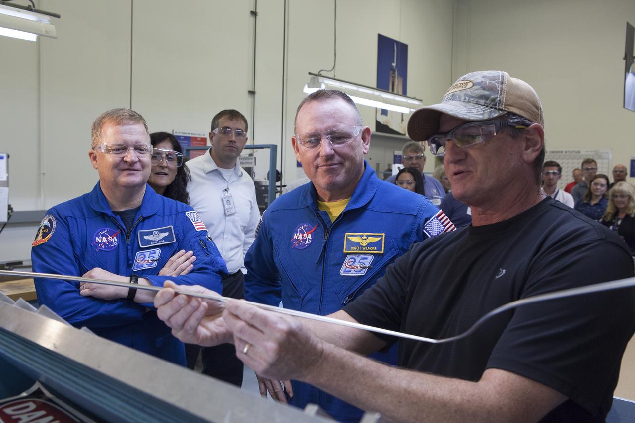
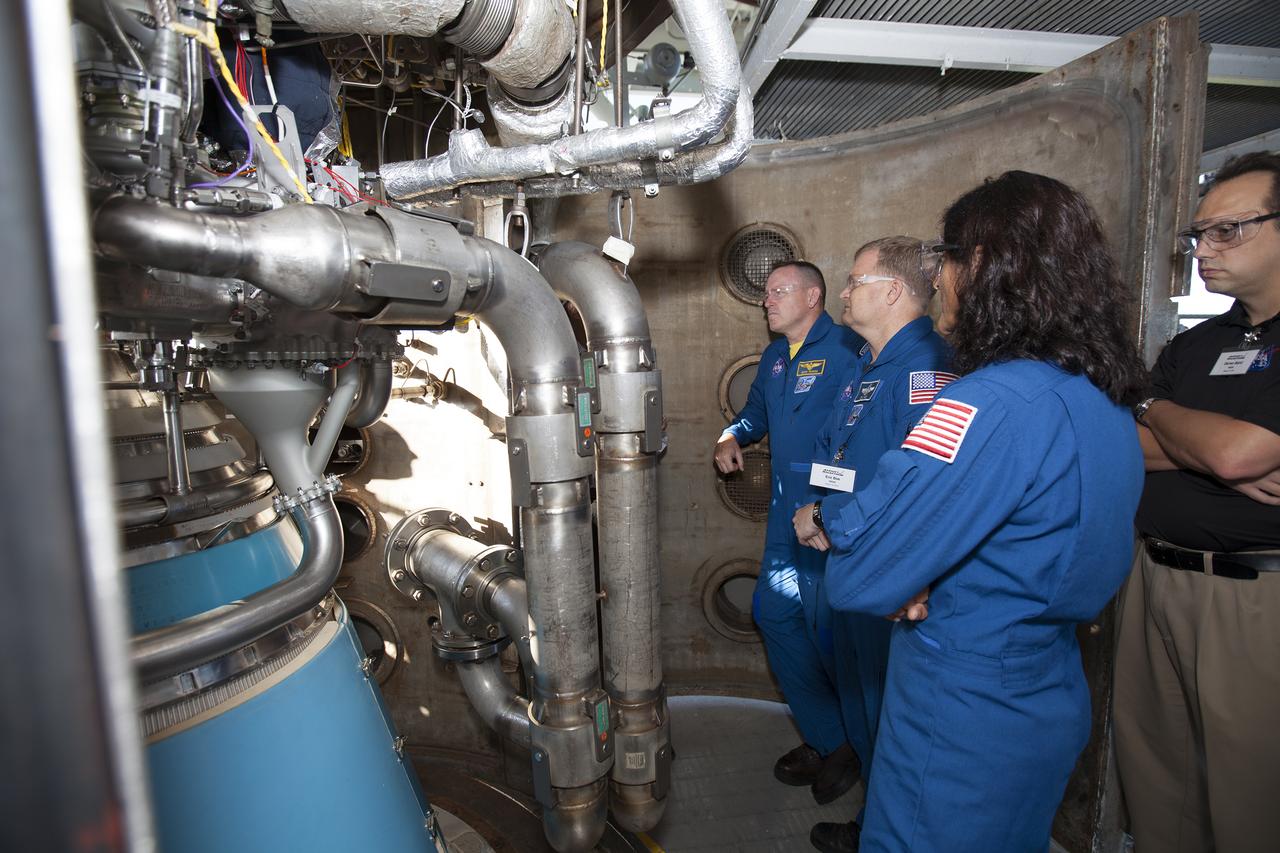
NASA astronauts Eric Boe, from left, and Barry "Butch" Wilmore listen as an Aerojet Rocketdyne engineer discusses aspects of an RL10 engine during a tour of Aerojet Rocketdyne's facility in West Palm Beach, Florida. The engine will be one of two used for the Centaur upper stage during a United Launch Alliance Atlas V mission to launch Boeing's CST-100 Starliner on a flight test carrying a crew. The engine was test-fired as part of acceptance testing to confirm the engine is ready for flight.
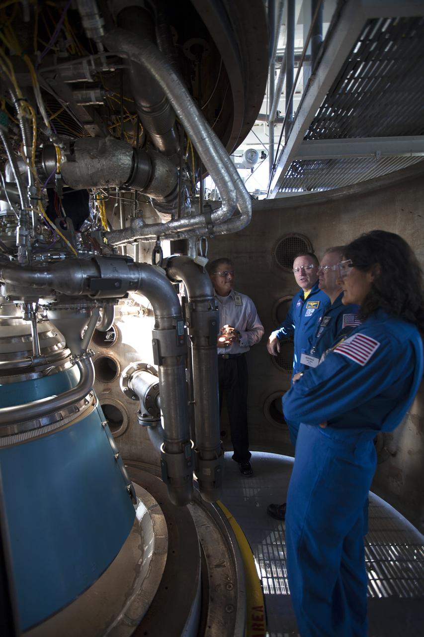
NASA astronauts Eric Boe, from left, Barry "Butch" Wilmore and Suni Williams listen as United Launch Alliance engineer Tom Harper discusses aspects of an RL10 engine during a tour of Aerojet Rocketdyne's facility in West Palm Beach, Florida. The engine will be one of two used for the Centaur upper stage during a United Launch Alliance Atlas V mission to launch Boeing's CST-100 Starliner on a flight test carrying a crew. The engine was test-fired as part of acceptance testing to confirm the engine is ready for flight.
Carlos Rodriguez, from left, manager of systems development, verification and testing for Aerojet Rocketdyne, talks with NASA astronauts Barry "Butch" Wilmore, Eric Boe and Suni Williams as the group surveys an RL10 engine as it stands in a vacuum chamber at Aerojet Rocketdyne's test stand in West Palm Beach, Florida. The engine will be one of two used for the Centaur upper stage during a United Launch Alliance Atlas V mission to launch Boeing's CST-100 Starliner on a flight test carrying a crew. The engine was test-fired as part of acceptance testing to confirm the engine is ready for flight.
Carlos Rodriguez, from left, manager of systems development, verification and testing for Aerojet Rocketdyne, talks with NASA astronauts Barry "Butch" Wilmore, Eric Boe and Suni Williams as the group surveys an RL10 engine as it stands in a vacuum chamber at Aerojet Rocketdyne's test stand in West Palm Beach, Florida. The engine will be one of two used for the Centaur upper stage during a United Launch Alliance Atlas V mission to launch Boeing's CST-100 Starliner on a flight test carrying a crew. The engine was test-fired as part of acceptance testing to confirm the engine is ready for flight.

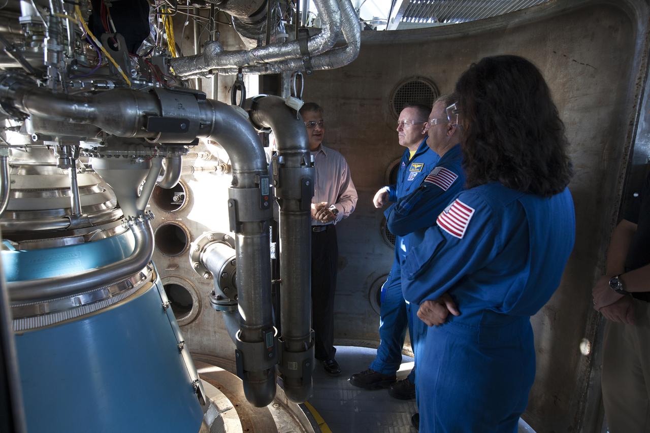
NASA Commercial Crew astronaut Eric Boe listens as Jim Moss, site director for Aerojet Rocketdyne's West Palm Beach facility, discusses aspects of the RL10 engine as it stands in a vacuum chamber at Aerojet Rocketdyne's test stand in West Palm Beach, Florida. The engine will be one of two used for the Centaur upper stage during a United Launch Alliance Atlas V mission to launch Boeing's CST-100 Starliner on a flight test carrying a crew. The engine was test-fired as part of acceptance testing to confirm the engine is ready for flight.
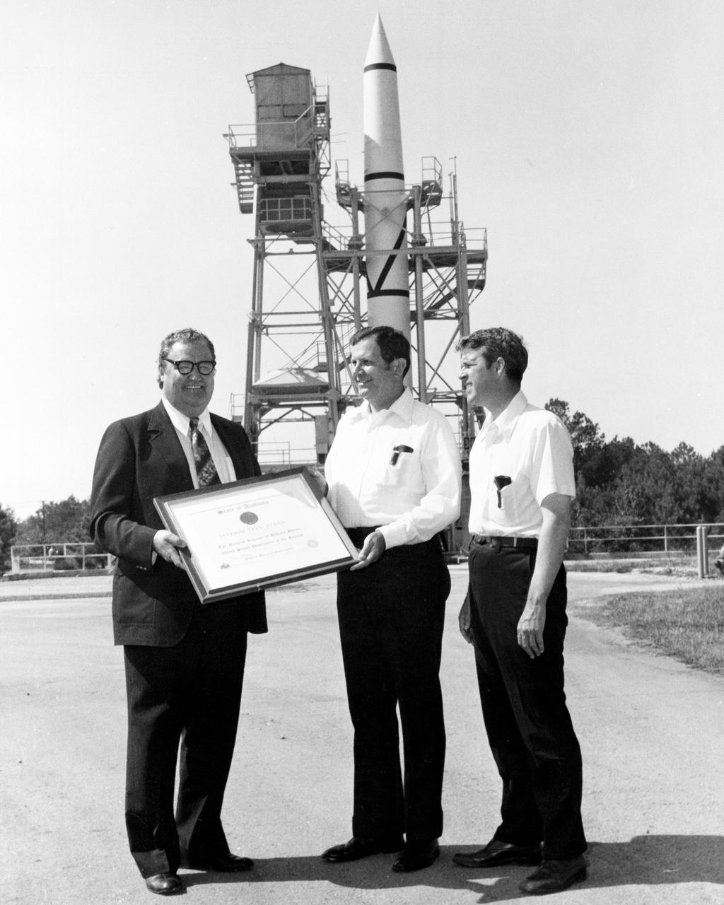
On October 02, 1976, Marshall Space Flight Center’s (MSFC) Redstone test stand was received into the National Registry of Historical Places. Photographed in front of the Redstone test stand are Dr. William R. Lucas, MSFC Center Director from June 15, 1974 until July 3, 1986, as he is accepting a certificate of registration from Madison County Commission Chairman James Record, and Huntsville architect Harvie Jones.

NASA test pilot Jim “Clue” Less sits inside the cockpit of the agency’s X-59 quiet supersonic research aircraft ahead of early morning engine runs at NASA’s Armstrong Flight Research Center in Edwards, California, on Thursday, March 12, 2026. The X-59 is part of NASA's Quesst mission, which seeks to demonstrate quiet supersonic flight and gather data that could help define acceptable sound for commercial supersonic travel over land.
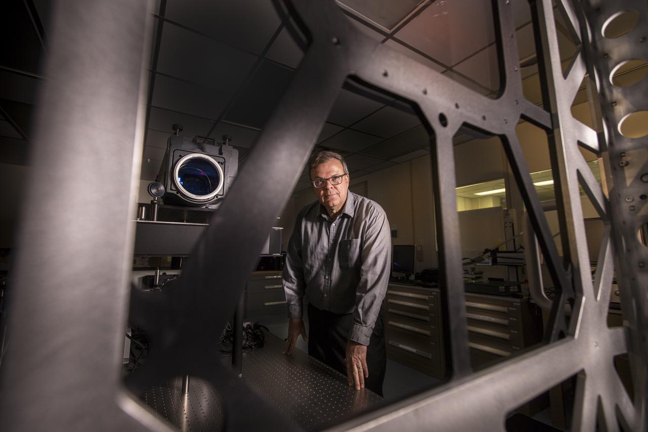
Mark Nurge, a physicist in Kennedy Space Center’s Applied Physics Lab, stands near a laser interferometer, which is used to determine if there are acceptable levels of distortion and imperfections in windows. Nurge recently completed optical metrology testing and evaluation of all flight windows on the Orion capsule for Artemis 1. The interferometer uses a laser source to do wavefront and transmission measurements, as well as evaluation of the color balance. Artemis 1 is an uncrewed flight that will pave the way for future crewed missions and enable future missions to the Moon, Mars, and beyond.
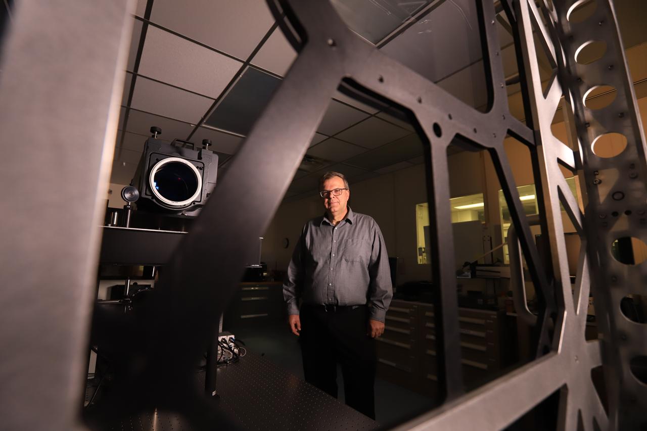
Mark Nurge, a physicist in Kennedy Space Center’s Applied Physics Lab, stands near a laser interferometer, which is used to determine if there are acceptable levels of distortion and imperfections in windows. Nurge recently completed optical metrology testing and evaluation of all flight windows on the Orion capsule for Artemis 1. The interferometer uses a laser source to do wavefront and transmission measurements, as well as evaluation of the color balance. Artemis 1 is an uncrewed flight that will pave the way for future crewed missions and enable future missions to the Moon, Mars, and beyond.
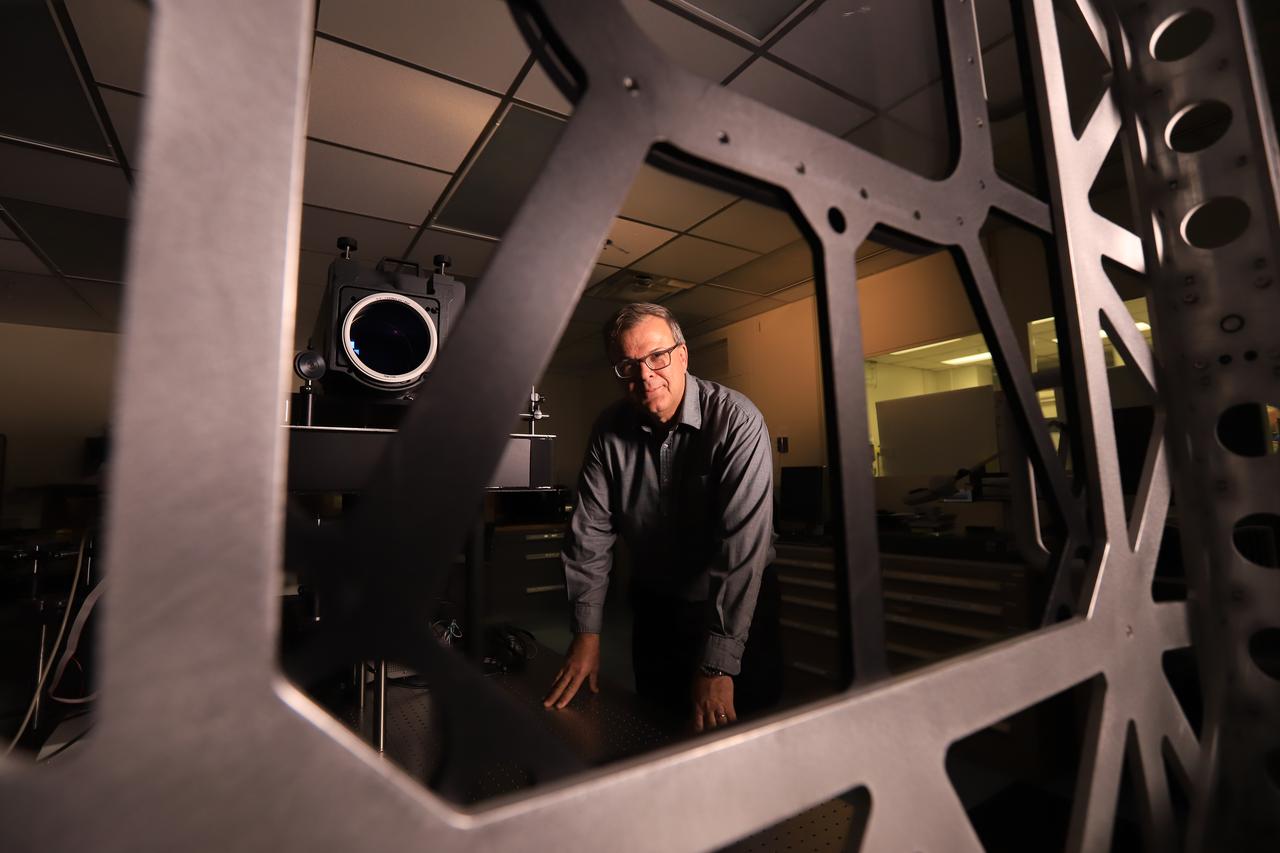
Mark Nurge, a physicist in Kennedy Space Center’s Applied Physics Lab, stands near a laser interferometer, which is used to determine if there are acceptable levels of distortion and imperfections in windows. Nurge recently completed optical metrology testing and evaluation of all flight windows on the Orion capsule for Artemis 1. The interferometer uses a laser source to do wavefront and transmission measurements, as well as evaluation of the color balance. Artemis 1 is an uncrewed flight that will pave the way for future crewed missions and enable future missions to the Moon, Mars, and beyond.
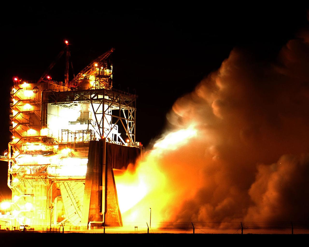
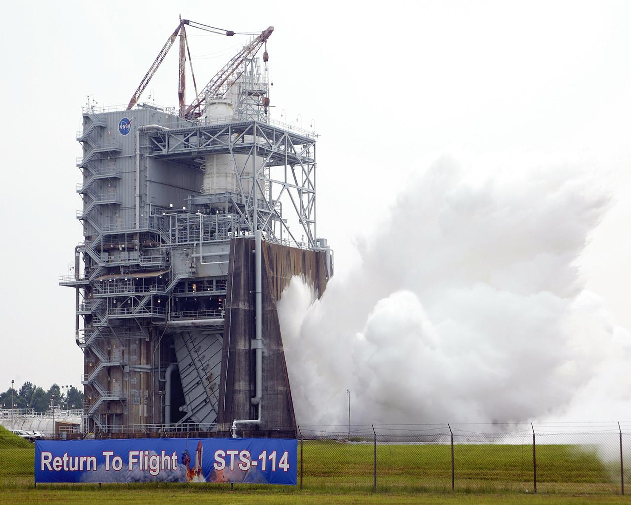
Water vapor surges from the flame deflector of the A-2 Test Stand at NASA's Stennis Space Center on Jan. 9 during the first space shuttle main engine test of the year. The test was an engine acceptance test of flight engine 2058. It's the first space shuttle main engine to be completely assembled at Kennedy Space Center. Objectives also included first-time (green run) tests of a high-pressure oxidizer turbo pump and an Advanced Health System Monitor engine controller. The test ran for the planned duration of 520 seconds.
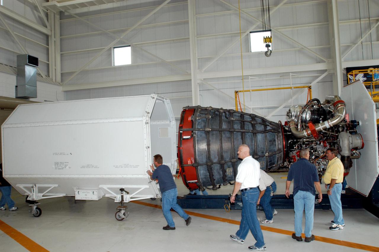
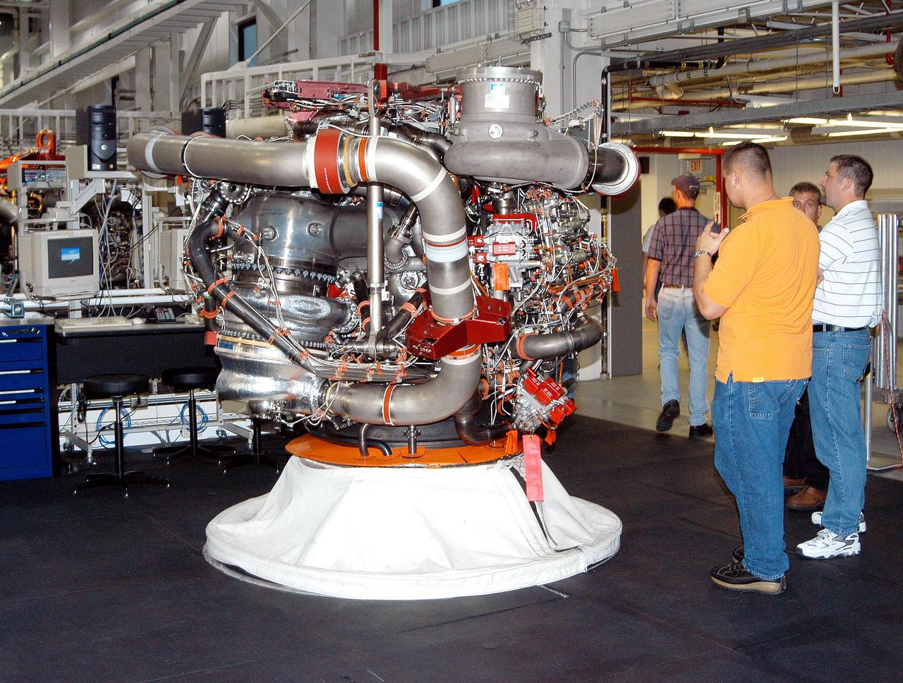
KENNEDY SPACE CENTER, FLA. - Inside the KSC Engine Shop, Boeing-Rocketdyne technicians remove the container that enclosed the third Space Shuttle Main Engine for Discovery’s Return to Flight mission STS-114. The engine is returning from NASA’s Stennis Space Center in Mississippi where it underwent a hot fire acceptance test. Typically, the engines are installed on an orbiter in the Orbiter Processing Facility approximately five months before launch.
KENNEDY SPACE CENTER, FLA. - Inside the KSC Engine Shop, Boeing-Rocketdyne technicians attach an overhead crane to the container enclosing the third Space Shuttle Main Engine for Discovery’s Return to Flight mission STS-114 arrives at the KSC Engine Shop aboard a trailer. The engine is returning from NASA’s Stennis Space Center in Mississippi where it underwent a hot fire acceptance test. Typically, the engines are installed on an orbiter in the Orbiter Processing Facility approximately five months before launch.
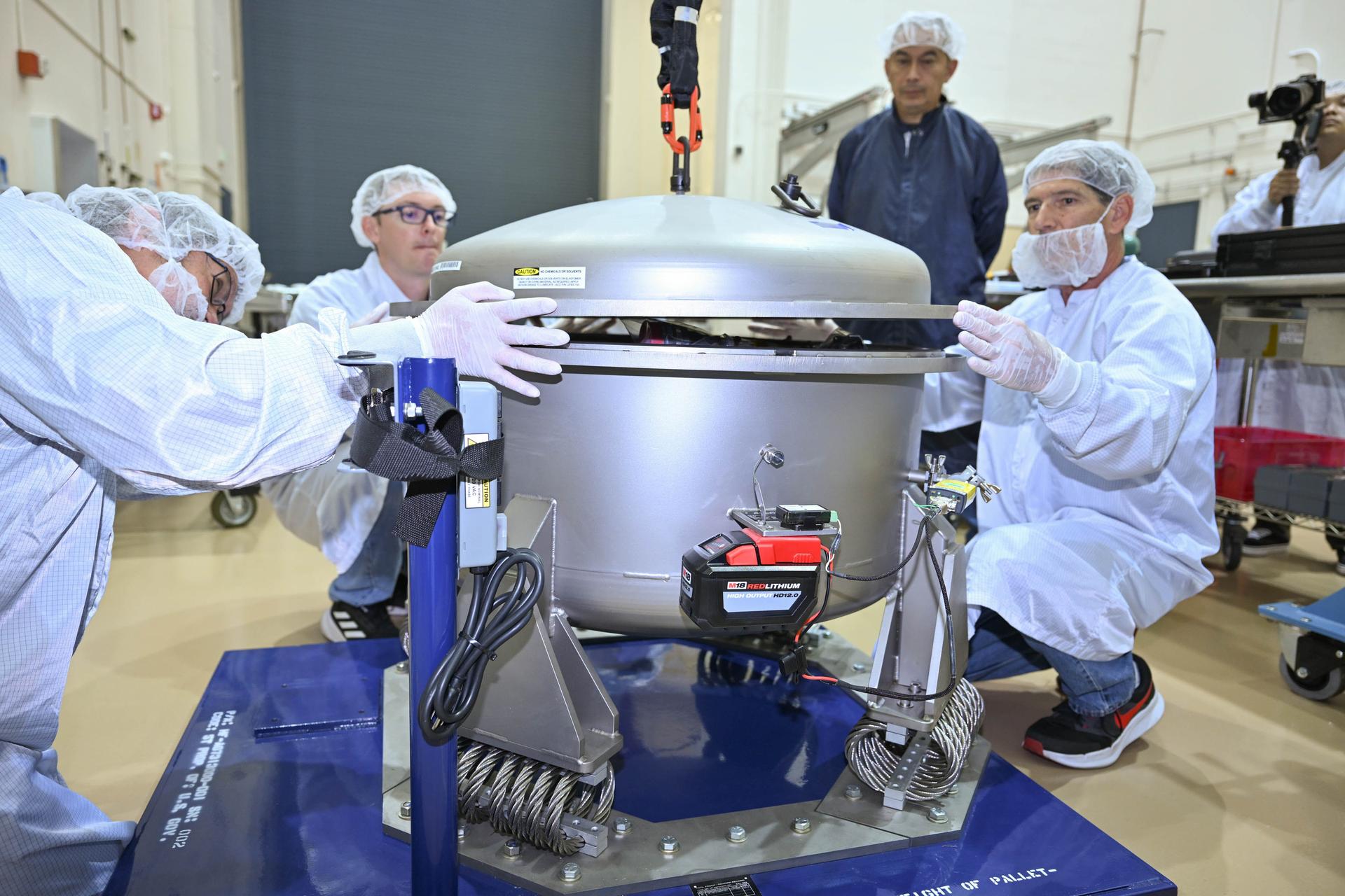
Technicians at Lanteris Space Systems in Palo Alto, California, remove the first of three Advanced Electric Propulsion System (AEPS) flight thrusters from its transport container following delivery from NASA’s Glenn Research Center. The thruster previously completed acceptance testing at Glenn and will be prepared for integration with Gateway’s Power and Propulsion Element (PPE). Credit: Lanteris Space Systems
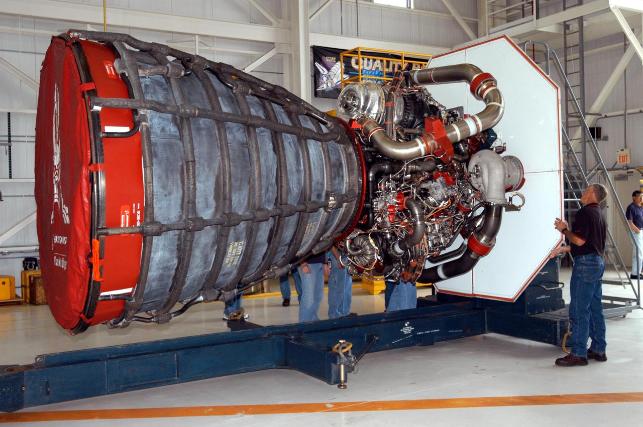
KENNEDY SPACE CENTER, FLA. - Inside the KSC Engine Shop, the third Space Shuttle Main Engine for Discovery’s Return to Flight mission STS-114 is secure on a stand. The engine has been returned from NASA’s Stennis Space Center in Mississippi where it underwent a hot fire acceptance test. Typically, the engines are installed on an orbiter in the Orbiter Processing Facility approximately five months before launch.
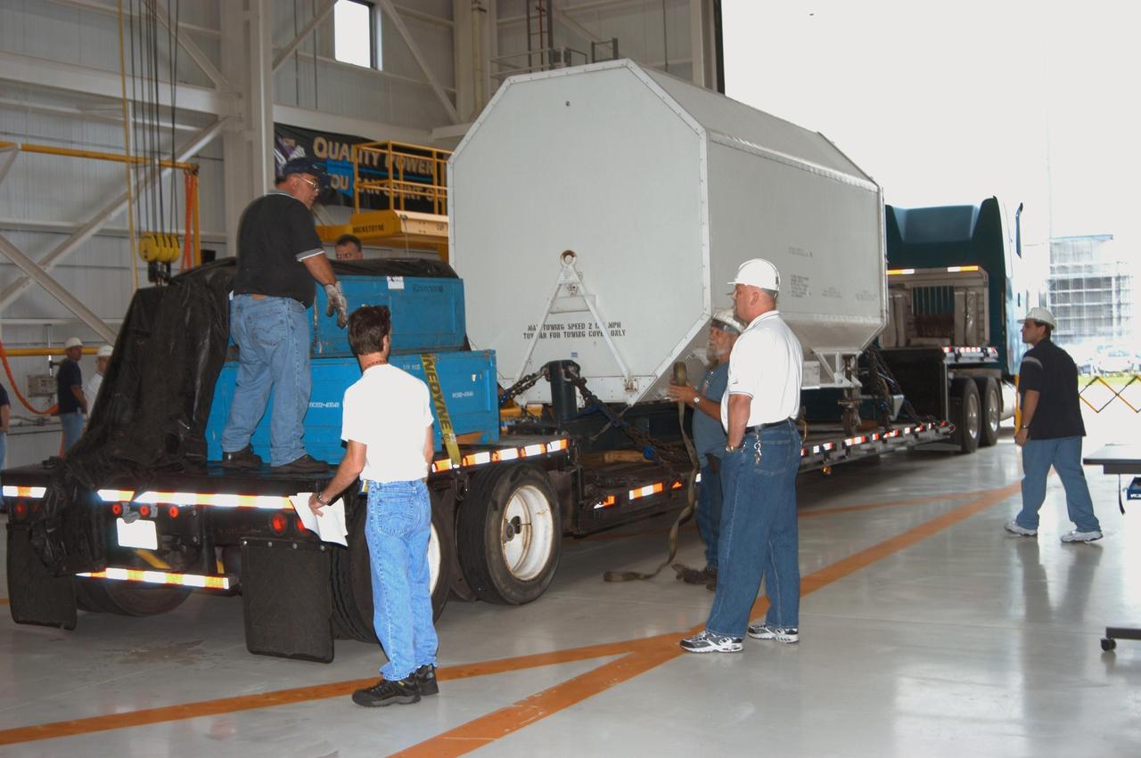
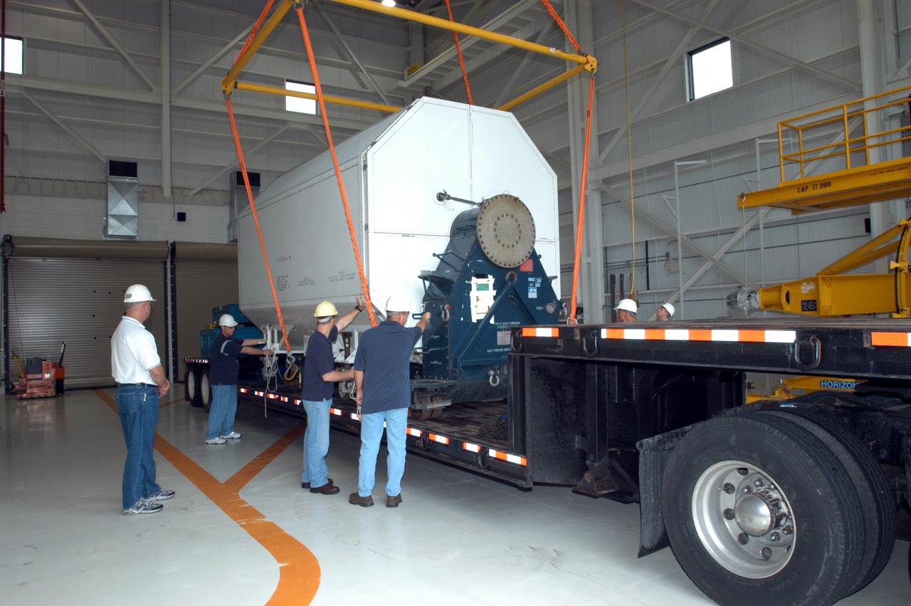
KENNEDY SPACE CENTER, FLA. - Enclosed inside the shipping container, the third Space Shuttle Main Engine for Discovery’s Return to Flight mission STS-114 arrives at the KSC Engine Shop aboard a trailer. The engine is returning from NASA’s Stennis Space Center in Mississippi where it underwent a hot fire acceptance test. Typically, the engines are installed on an orbiter in the Orbiter Processing Facility approximately five months before launch.
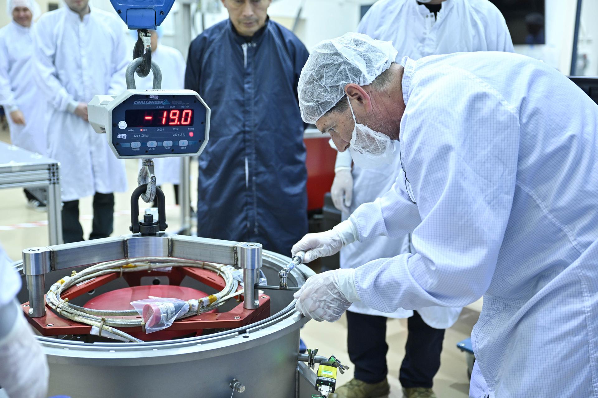
Technicians at Lanteris Space Systems in Palo Alto, California, remove the first of three Advanced Electric Propulsion System (AEPS) flight thrusters from its transport container following delivery from NASA’s Glenn Research Center. The thruster previously completed acceptance testing at Glenn and will be prepared for integration with Gateway’s Power and Propulsion Element (PPE).
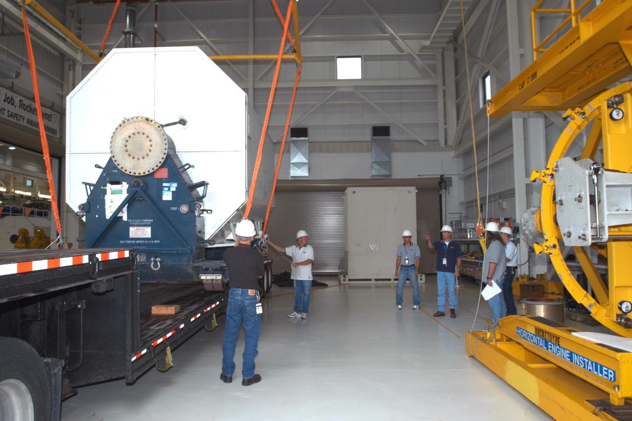
KENNEDY SPACE CENTER, FLA. - Inside the KSC Engine Shop, the third Space Shuttle Main Engine for Discovery’s Return to Flight mission STS-114 is ready to be lifted off the trailer. The engine is returning from NASA’s Stennis Space Center in Mississippi where it underwent a hot fire acceptance test. Typically, the engines are installed on an orbiter in the Orbiter Processing Facility approximately five months before launch.
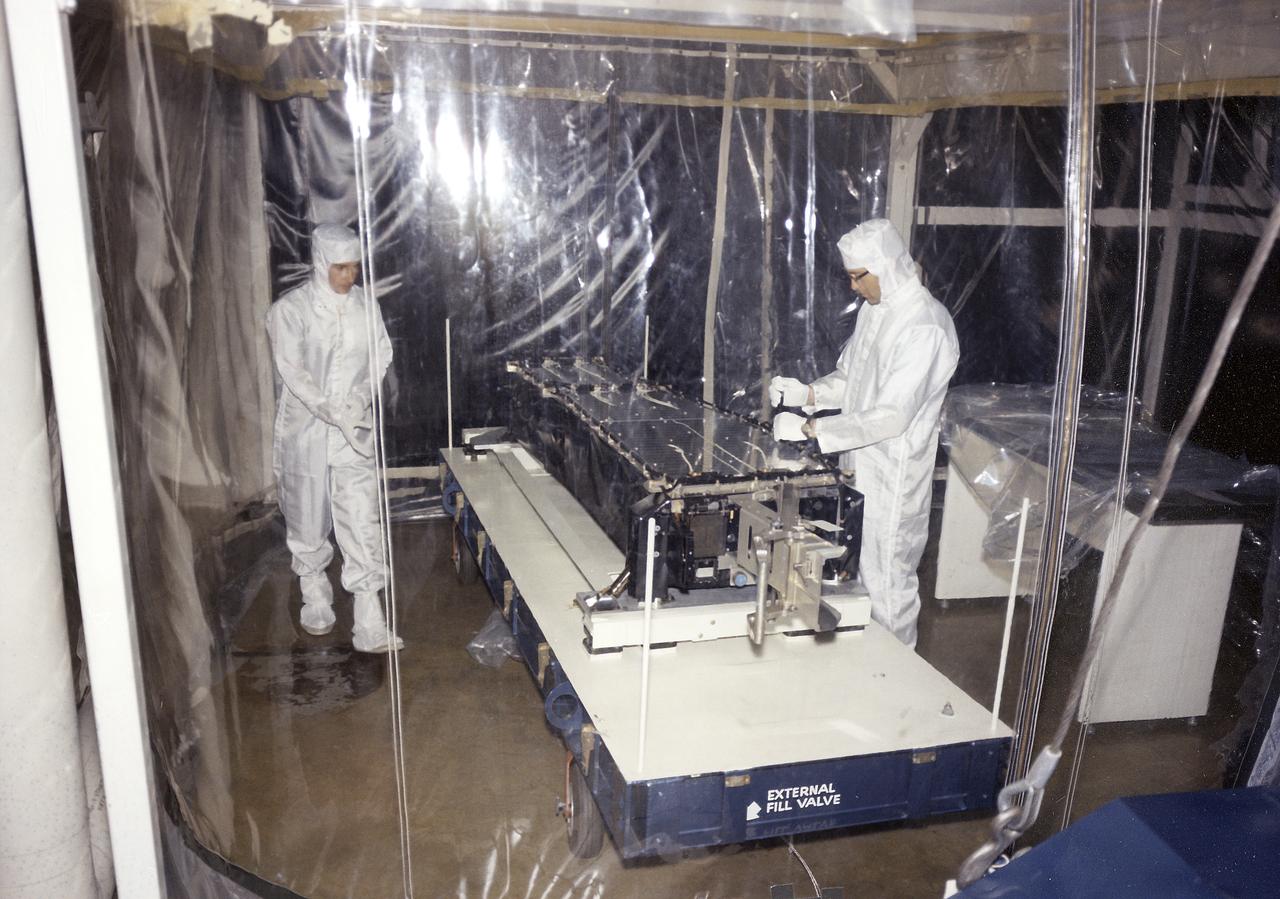
This photograph shows Skylab's Extreme Ultraviolet (XUV) Spectroheliograph during an acceptance test and checkout procedures in April 1971. The unit was an Apollo Telescope Mount (ATM) instrument designed to sequentially photograph the solar chromosphere and corona in selected ultraviolet wavelengths. The instrument also obtained information about composition, temperature, energy conversion and transfer, and plasma processes of the chromosphere and lower corona. The Marshall Space Flight Center had program management responsibility for the development of Skylab hardware and experiments.
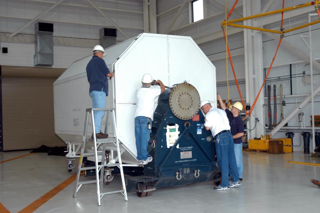
KENNEDY SPACE CENTER, FLA. - Inside the KSC Engine Shop, Boeing-Rocketdyne technicians begin removing the end of the container enclosing the third Space Shuttle Main Engine for Discovery’s Return to Flight mission STS-114. The engine is returning from NASA’s Stennis Space Center in Mississippi where it underwent a hot fire acceptance test. Typically, the engines are installed on an orbiter in the Orbiter Processing Facility approximately five months before launch.
KENNEDY SPACE CENTER, FLA. - Inside the KSC Engine Shop, Boeing-Rocketdyne technicians secure on a stand the third Space Shuttle Main Engine for Discovery’s Return to Flight mission STS-114. The engine is returning from NASA’s Stennis Space Center in Mississippi where it underwent a hot fire acceptance test. Typically, the engines are installed on an orbiter in the Orbiter Processing Facility approximately five months before launch.
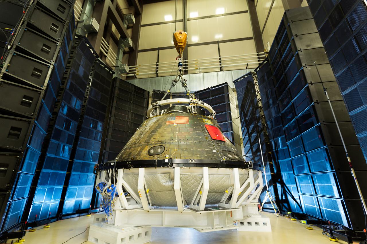
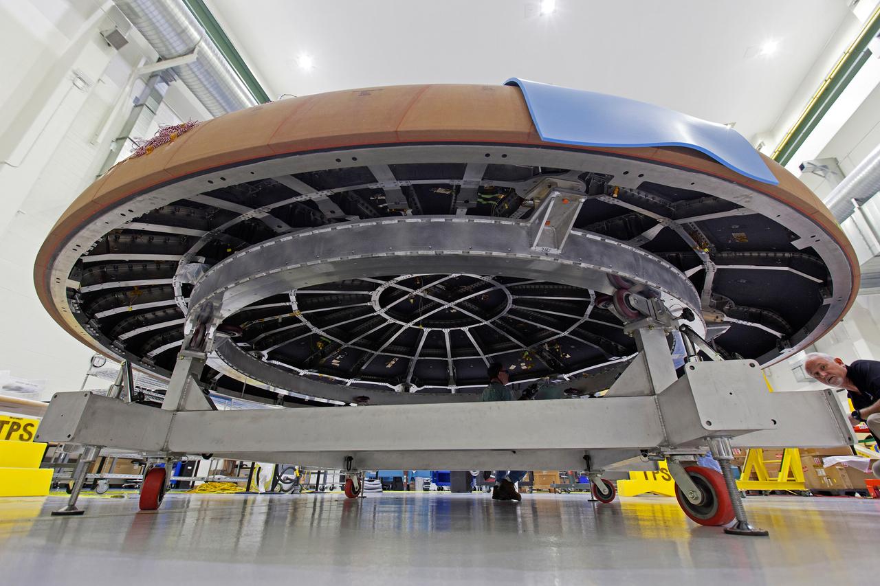
Direct Field Acoustic (DFA) Testing was successfully completed on the Exploration Flight Test-1 (EFT-1) crew module at the Lockheed Martin Waterton Reverberant Acoustic Lab (RAL) on March 1, 2016. DFA Testing is an alternative method for spacecraft module acoustic qualification and acceptance verification that is being investigated for use in the Orion program. Its portability would allow testing at KSC and eliminate the transportation risks and associated cost and schedule of performing this verification activity off-site. Two configurations were tested; one representing the future reverberant acoustic comparison test and one representing the future configuration for the Artemis I crew module. A mock-up of the service module without the fairings will also be tested to gather volumetric data to decide viability of performing DFA Testing on the Static Test Article (STA) SM in the 2016 Fall. Data will be used to develop predictive algorithms for future tests.
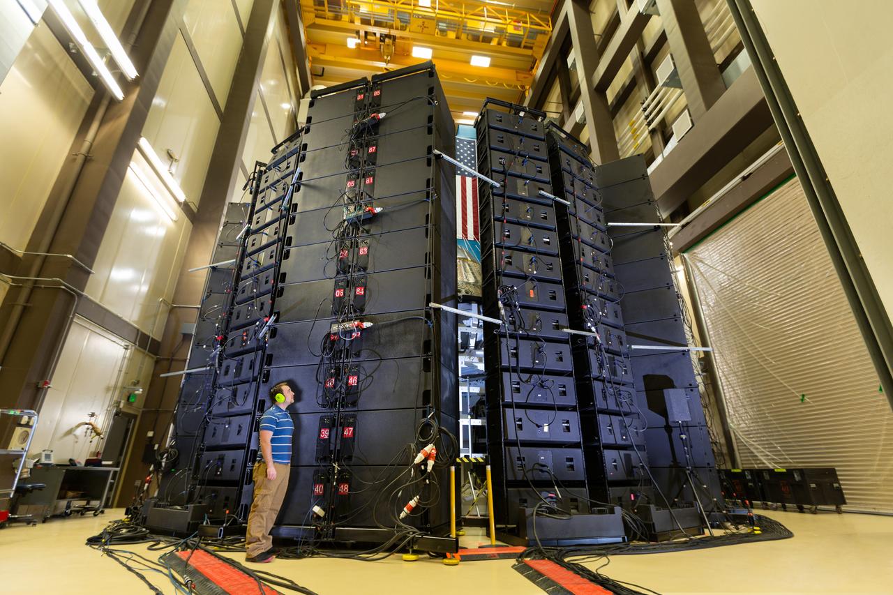
Direct Field Acoustic (DFA) Testing was successfully completed on the Exploration Flight Test-1 (EFT-1) crew module at the Lockheed Martin Waterton Reverberant Acoustic Lab (RAL) on March 1, 2016. DFA Testing is an alternative method for spacecraft module acoustic qualification and acceptance verification that is being investigated for use in the Orion program. Its portability would allow testing at KSC and eliminate the transportation risks and associated cost and schedule of performing this verification activity off-site. Two configurations were tested; one representing the future reverberant acoustic comparison test and one representing the future configuration for the Artemis I crew module. A mock-up of the service module without the fairings will also be tested to gather volumetric data to decide viability of performing DFA Testing on the Static Test Article (STA) SM in the 2016 Fall. Data will be used to develop predictive algorithms for future tests.

Direct Field Acoustic (DFA) Testing was successfully completed on the Exploration Flight Test-1 (EFT-1) crew module at the Lockheed Martin Waterton Reverberant Acoustic Lab (RAL) on March 1, 2016. DFA Testing is an alternative method for spacecraft module acoustic qualification and acceptance verification that is being investigated for use in the Orion program. Its portability would allow testing at KSC and eliminate the transportation risks and associated cost and schedule of performing this verification activity off-site. Two configurations were tested; one representing the future reverberant acoustic comparison test and one representing the future configuration for the Artemis I crew module. A mock-up of the service module without the fairings will also be tested to gather volumetric data to decide viability of performing DFA Testing on the Static Test Article (STA) SM in the 2016 Fall. Data will be used to develop predictive algorithms for future tests.
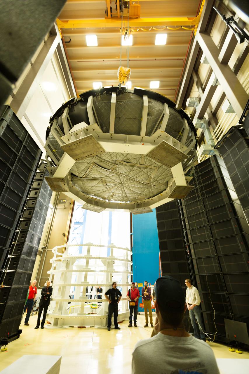
Direct Field Acoustic (DFA) Testing was successfully completed on the Exploration Flight Test-1 (EFT-1) crew module at the Lockheed Martin Waterton Reverberant Acoustic Lab (RAL) on March 1, 2016. DFA Testing is an alternative method for spacecraft module acoustic qualification and acceptance verification that is being investigated for use in the Orion program. Its portability would allow testing at KSC and eliminate the transportation risks and associated cost and schedule of performing this verification activity off-site. Two configurations were tested; one representing the future reverberant acoustic comparison test and one representing the future configuration for the Artemis I crew module. A mock-up of the service module without the fairings will also be tested to gather volumetric data to decide viability of performing DFA Testing on the Static Test Article (STA) SM in the 2016 Fall. Data will be used to develop predictive algorithms for future tests.

Direct Field Acoustic (DFA) Testing was successfully completed on the Exploration Flight Test-1 (EFT-1) crew module at the Lockheed Martin Waterton Reverberant Acoustic Lab (RAL) on March 1, 2016. DFA Testing is an alternative method for spacecraft module acoustic qualification and acceptance verification that is being investigated for use in the Orion program. Its portability would allow testing at KSC and eliminate the transportation risks and associated cost and schedule of performing this verification activity off-site. Two configurations were tested; one representing the future reverberant acoustic comparison test and one representing the future configuration for the Artemis I crew module. A mock-up of the service module without the fairings will also be tested to gather volumetric data to decide viability of performing DFA Testing on the Static Test Article (STA) SM in the 2016 Fall. Data will be used to develop predictive algorithms for future tests.
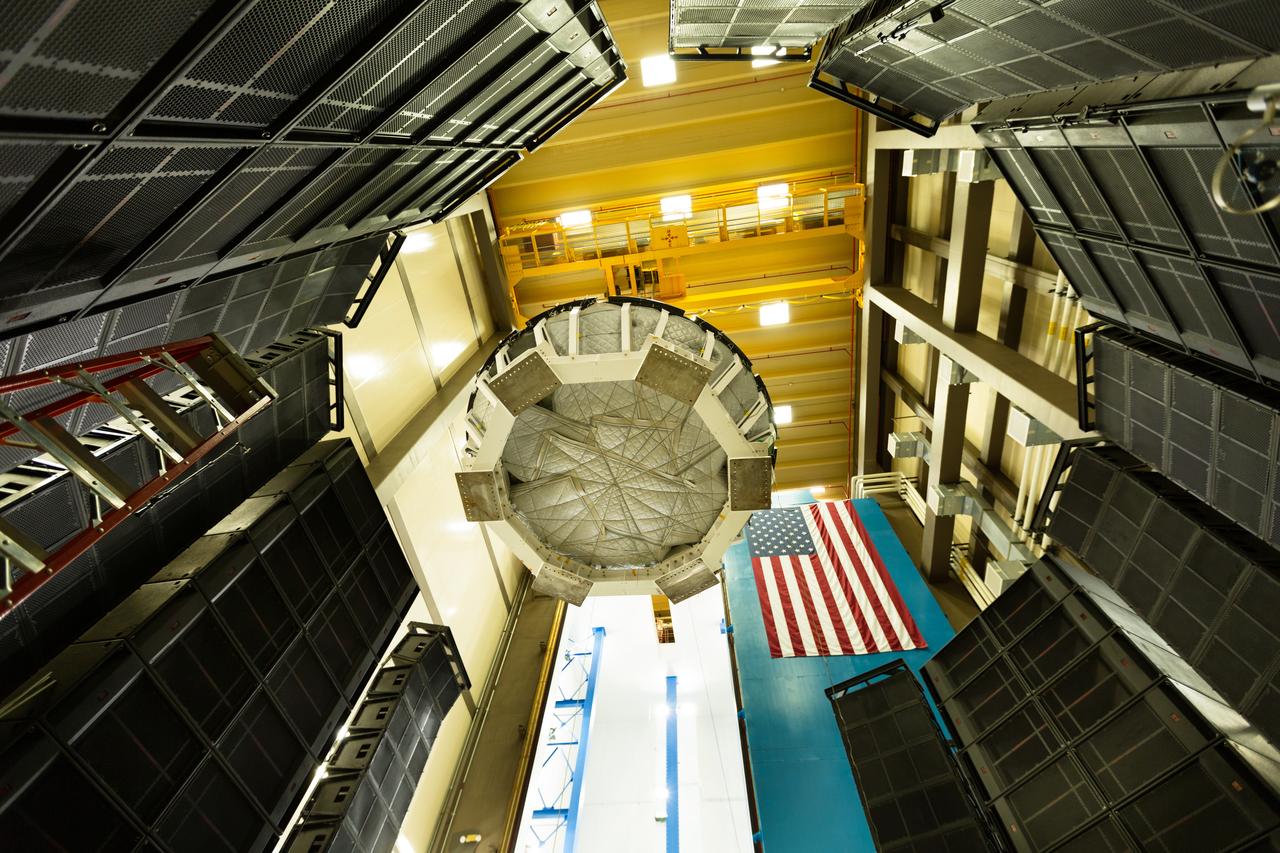
Direct Field Acoustic (DFA) Testing was successfully completed on the Exploration Flight Test-1 (EFT-1) crew module at the Lockheed Martin Waterton Reverberant Acoustic Lab (RAL) on March 1, 2016. DFA Testing is an alternative method for spacecraft module acoustic qualification and acceptance verification that is being investigated for use in the Orion program. Its portability would allow testing at KSC and eliminate the transportation risks and associated cost and schedule of performing this verification activity off-site. Two configurations were tested; one representing the future reverberant acoustic comparison test and one representing the future configuration for the Artemis I crew module. A mock-up of the service module without the fairings will also be tested to gather volumetric data to decide viability of performing DFA Testing on the Static Test Article (STA) SM in the 2016 Fall. Data will be used to develop predictive algorithms for future tests.
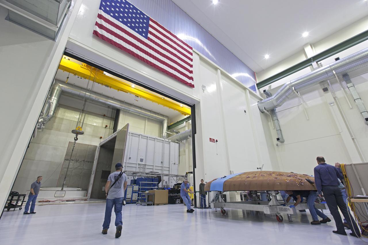
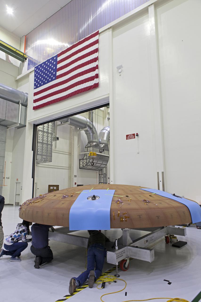
Technicians move the Orion heat shield for Exploration Mission-1 toward the thermal chamber in the Neil Armstrong Operations and Checkout Building high bay at NASA's Kennedy Space Center in Florida. Protective pads are being attached to the heat shield surface. The heat shield will undergo a thermal cycle test to verify acceptable workmanship and material quality. The test also serves to verify the heat shield's thermal protection systems have been manufactured and assembled correctly. The Orion spacecraft will launch atop NASA's Space Launch System rocket on its first uncrewed integrated flight.
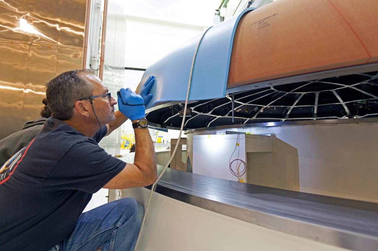
A technician checks the Orion heat shield for Artemis I before it is moved into the thermal chamber in the Neil Armstrong Operations and Checkout Building high bay at NASA's Kennedy Space Center in Florida on Oct. 23, 2017. Protective pads were attached to the heat shield surface. The heat shield will undergo a thermal cycle test to verify acceptable workmanship and material quality. The test also serves to verify the heat shield's thermal protection systems have been manufactured and assembled correctly. The Orion spacecraft will launch atop NASA's Space Launch System rocket on it first uncrewed integrated flight.
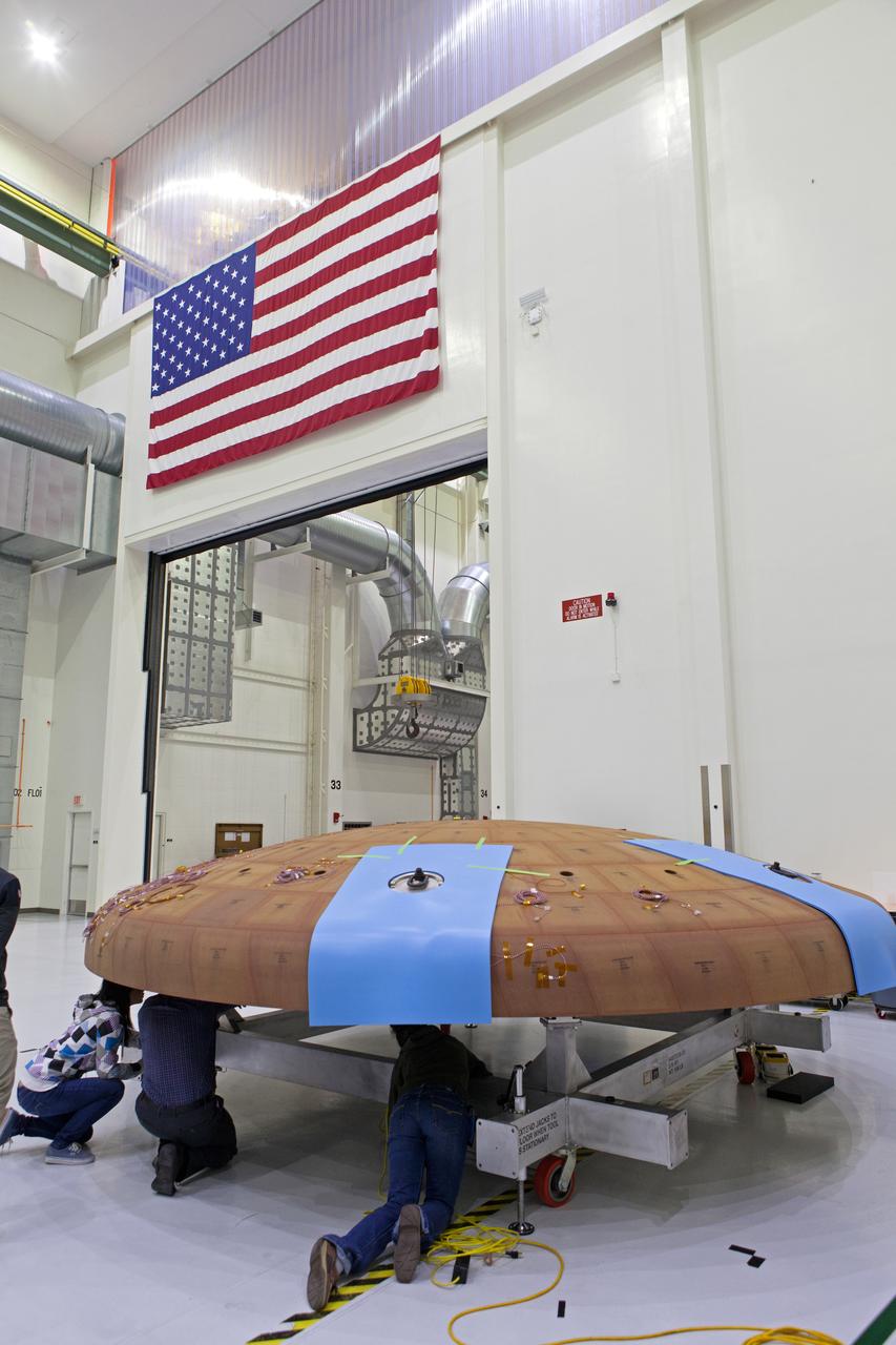
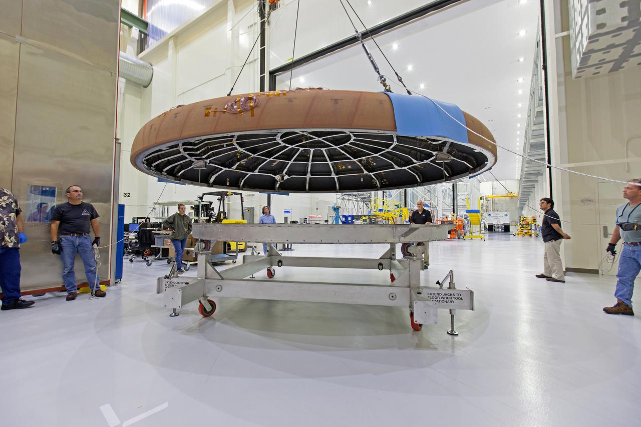
Lockheed Martin engineers and technicians prepare the Orion heat shield for Artemis I for its move to the thermal chamber in the Neil Armstrong Operations and Checkout Building high bay at NASA's Kennedy Space Center in Florida on Oct. 23, 2017. The heat shield will undergo a thermal cycle test to verify acceptable workmanship and material quality. The test serves to verify the heat shield's thermal protection systems have been manufactured and assembled correctly. The Orion spacecraft will launch atop NASA's Space Launch System rocket on its first uncrewed integrated flight.
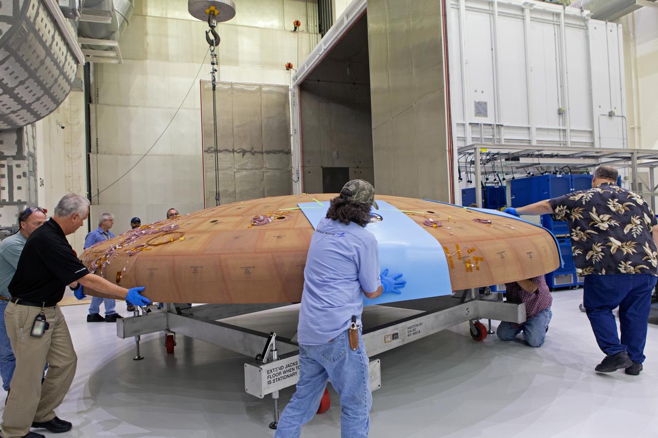
Technicians move the Orion heat shield for Artemis I toward the thermal chamber in the Neil Armstrong Operations and Checkout Building high bay at NASA's Kennedy Space Center in Florida on Oct. 23, 2017. Protective pads were attached to the heat shield surface. The heat shield will undergo a thermal cycle test to verify acceptable workmanship and material quality. The test also serves to verify the heat shield's thermal protection systems have been manufactured and assembled correctly. The Orion spacecraft will launch atop NASA's Space Launch System rocket on it first uncrewed integrated flight.
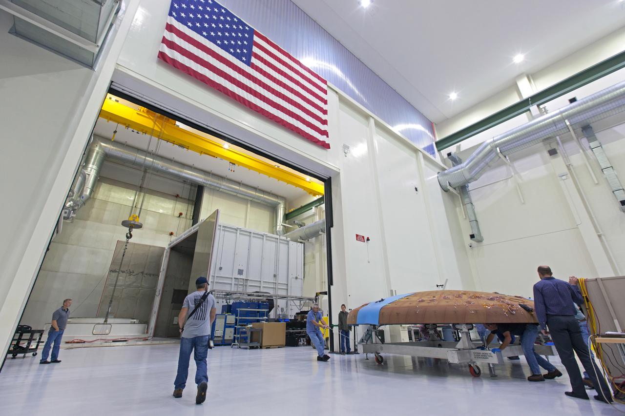
Technicians move the Orion heat shield for Artemis I toward the thermal chamber in the Neil Armstrong Operations and Checkout Building high bay at NASA's Kennedy Space Center in Florida on Oct. 23, 2017. Protective pads were attached to the heat shield surface. The heat shield will undergo a thermal cycle test to verify acceptable workmanship and material quality. The test also serves to verify the heat shield's thermal protection systems have been manufactured and assembled correctly. The Orion spacecraft will launch atop NASA's Space Launch System rocket on it first uncrewed integrated flight.
The Orion heat shield for Artemis I is being prepared for its move to the thermal chamber in the Neil Armstrong Operations and Checkout Building high bay at NASA's Kennedy Space Center in Florida on Oct. 23, 2017. Protective pads are being attached to the heat shield surface. The heat shield will undergo a thermal cycle test to verify acceptable workmanship and material quality. The test also serves to verify the heat shield's thermal protection systems have been manufactured and assembled correctly. The Orion spacecraft will launch atop NASA's Space Launch System rocket on its first uncrewed integrated flight.
Lockheed Martin engineers and technicians prepare the Orion heat shield for Exploration Mission-1 for its move to the thermal chamber in the Neil Armstrong Operations and Checkout Building high bay at NASA's Kennedy Space Center in Florida. The heat shield will undergo a thermal cycle test to verify acceptable workmanship and material quality. The test serves to verify the heat shield's thermal protection systems have been manufactured and assembled correctly. The Orion spacecraft will launch atop NASA's Space Launch System rocket on its first uncrewed integrated flight.
A crane attached to the Orion heat shield for Artemis I moves it toward the thermal chamber in the Neil Armstrong Operations and Checkout Building high bay at NASA's Kennedy Space Center in Florida on Oct. 23, 2017. Protective pads were attached to the heat shield surface. The heat shield will undergo a thermal cycle test to verify acceptable workmanship and material quality. The test also serves to verify the heat shield's thermal protection systems have been manufactured and assembled correctly. The Orion spacecraft will launch atop NASA's Space Launch System rocket on it first uncrewed integrated flight.
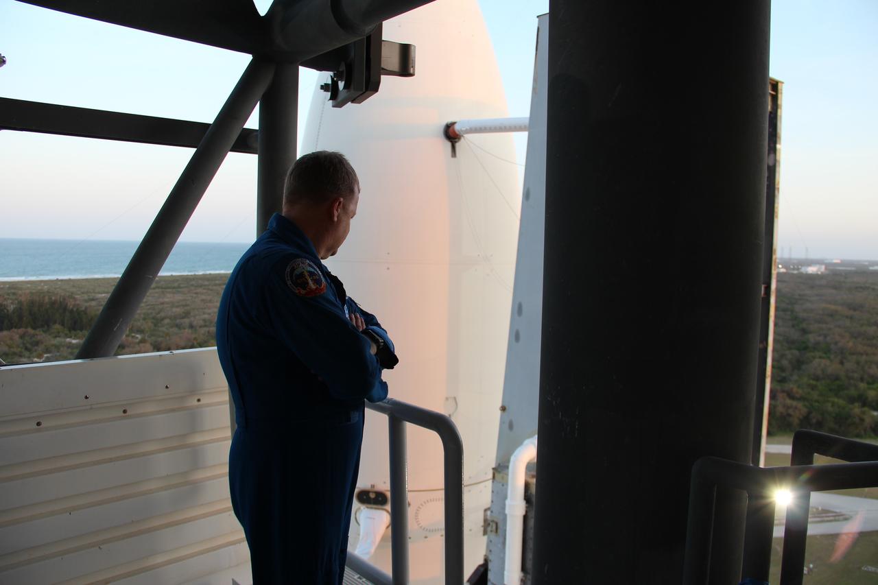
NASA astronaut Eric Boe, one of four astronauts working with the agency’s Commercial Crew Program, checked out the Crew Access Tower at Space Launch Complex 41. Here, Boe is standing right above the crew access arm, which astronauts will use to board Boeing’s Starliner spacecraft installed atop an Atlas V launch vehicle. Accompanied by NASA, Boeing and ULA engineers, Boe inspected the launch tower to establish whether spotlight and lighting conditions will be acceptable after dark. The survey was required to ensure crew members will have suitable visibility as they prepare to board Boeing’s Starliner spacecraft and launch on missions such as the Crew Flight Test to the International Space Station, targeted for later this year.
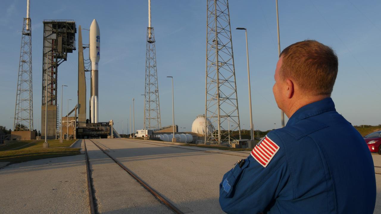
NASA astronaut Eric Boe, one of four astronauts working with the agency’s Commercial Crew Program, had the opportunity to check out the Crew Access Tower at Space Launch Complex 41 (SLC-41) Wednesday with a United Launch Alliance Atlas V on the pad. Boe, along with launch operations engineers from NASA, Boeing, and ULA, climbed the launch pad tower to evaluate lighting and spotlights after dark. The survey helped ensure crew members will have acceptable visibility as they prepare to launch aboard Boeing’s Starliner spacecraft on the Crew Flight Test to the International Space Station targeted for later this year.
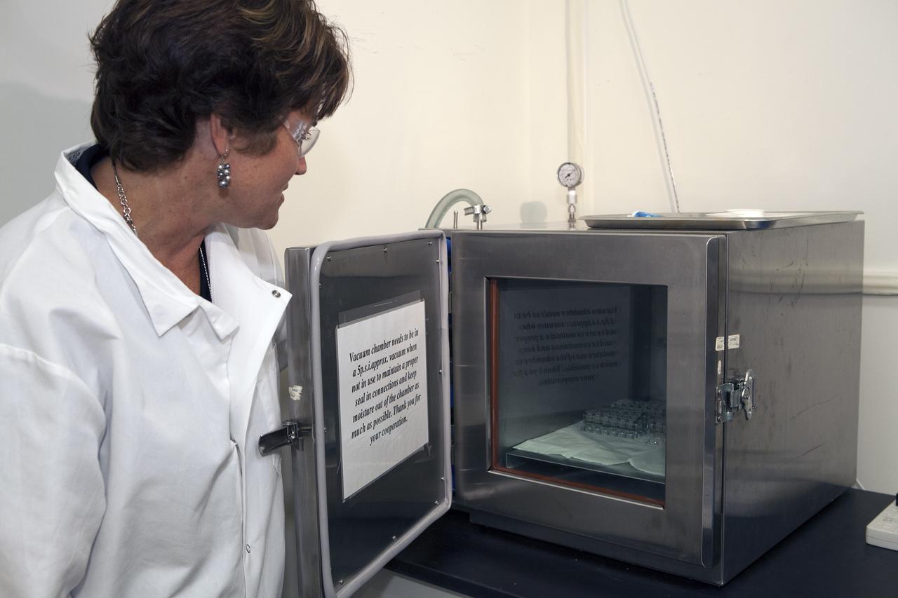
CAPE CANAVERAL, Fla. – Inside a laboratory in the Space Station Processing Facility at NASA's Kennedy Space Center in Florida, April Spinale, a payload integration specialist with Bionetics, places a set of vials for the Protein Crystal Growth 2 experiment into a vacuum chamber for an acceptance leak test. The vials have been filled with clear water and the test will verify that the hardware is providing adequate containment for the liquids. Spinale is a consultants for the Center for Advancement of Science in Space, or CASIS. The experiment is one of many that will be delivered to the International Space Station on the SpaceX-4 commercial cargo resupply mission. Kennedy's ISS Ground Processing and Research Project Office is providing the necessary laboratories, equipment, supplies and consumables for 61 principal investigators, including 17 from other countries, as they prepare their science experiments for flight. The SpaceX-4 flight is targeted to launch in September 2014. Photo credit: NASA/Dimitri Gerondidakis
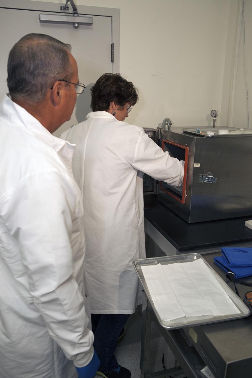
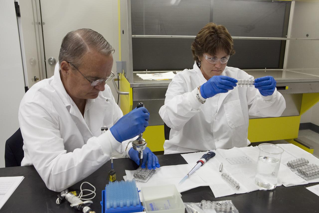
CAPE CANAVERAL, Fla. – Inside a laboratory in the Space Station Processing Facility at NASA's Kennedy Space Center in Florida, April Spinale, a payload integration specialist with Bionetics, and Ray Polniak, a quality assurance specialist with Dynamac, place a set of vials for the Protein Crystal Growth 2 experiment into a vacuum chamber for an acceptance leak test. The vials have been filled with clear water. The test will verify that the hardware is providing adequate containment for the liquids. Both are consultants for the Center for Advancement of Science in Space, or CASIS. The experiment is one of many that will be delivered to the International Space Station on the SpaceX-4 commercial cargo resupply mission. Kennedy's ISS Ground Processing and Research Project Office is providing the necessary laboratories, equipment, supplies and consumables for 61 principal investigators, including 17 from other countries, as they prepare their science experiments for flight. The SpaceX-4 flight is targeted to launch in September 2014. Photo credit: NASA/Dimitri Gerondidakis
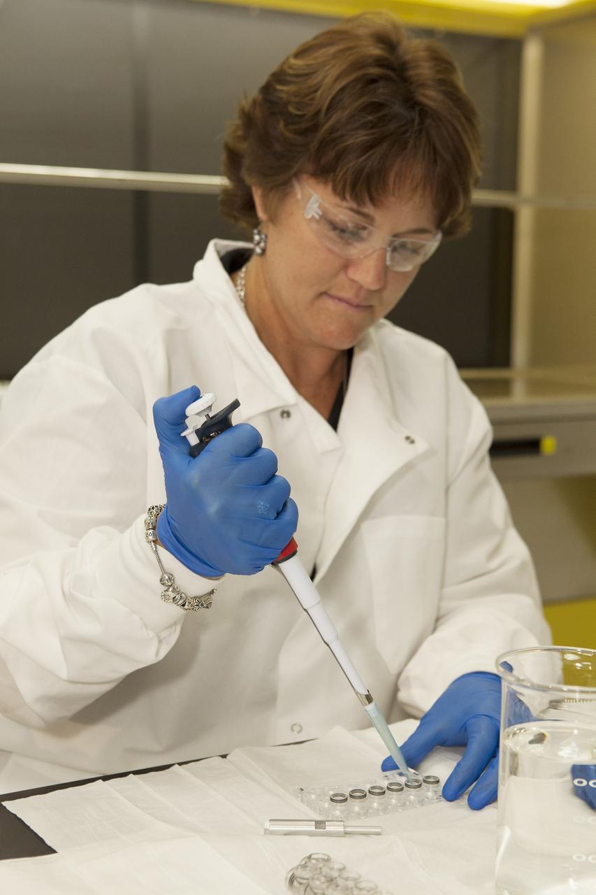
CAPE CANAVERAL, Fla. – Inside a laboratory in the Space Station Processing Facility at NASA's Kennedy Space Center in Florida, April Spinale, a payload integration specialist with Bionetics, fills vials with clear water during an acceptance leak test on the hardware for the Protein Crystal Growth 2 experiment. Spinale is a consultant for the Center for Advancement of Science in Space, or CASIS. The experiment is one of many that will be delivered to the International Space Station on the SpaceX-4 commercial cargo resupply mission. Kennedy's ISS Ground Processing and Research Project Office is providing the necessary laboratories, equipment, supplies and consumables for 61 principal investigators, including 17 from other countries, as they prepare their science experiments for flight. The SpaceX-4 flight is targeted to launch in September 2014. Photo credit: NASA/Dimitri Gerondidakis
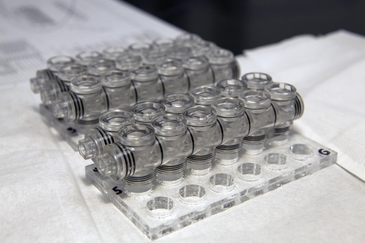
CAPE CANAVERAL, Fla. – Inside a laboratory in the Space Station Processing Facility at NASA's Kennedy Space Center in Florida, vials for the Protein Crystal Growth 2 experiment are being prepared for an acceptance leak test. The vials will be filled with clear water and then put in a vacuum chamber to verify that they are providing adequate containment for liquids. The experiment is one of many that will be delivered to the International Space Station on the SpaceX-4 commercial cargo resupply mission. Kennedy's ISS Ground Processing and Research Project Office is providing the necessary laboratories, equipment, supplies and consumables for 61 principal investigators, including 17 from other countries, as they prepare their science experiments for flight. The SpaceX-4 flight is targeted to launch in September 2014. Photo credit: NASA/Dimitri Gerondidakis
CAPE CANAVERAL, Fla. – Inside a laboratory in the Space Station Processing Facility at NASA's Kennedy Space Center in Florida, April Spinale, a payload integration specialist with Bionetics, and Ray Polniak, a quality assurance specialist with Dynamac, fill vials with clear water during an acceptance leak test on the hardware for the Protein Crystal Growth 2 experiment. They are both consultants for the Center for Advancement of Science in Space, or CASIS. The experiment is one of many that will be delivered to the International Space Station on the SpaceX-4 commercial cargo resupply mission. Kennedy's ISS Ground Processing and Research Project Office is providing the necessary laboratories, equipment, supplies and consumables for 61 principal investigators, including 17 from other countries, as they prepare their science experiments for flight. The SpaceX-4 flight is targeted to launch in September 2014. Photo credit: NASA/Dimitri Gerondidakis
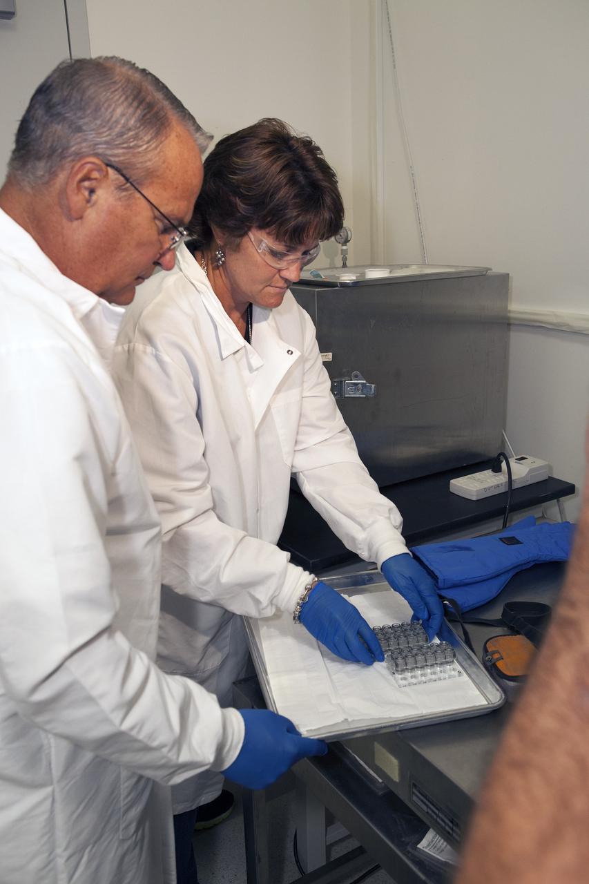
CAPE CANAVERAL, Fla. – Inside a laboratory in the Space Station Processing Facility at NASA's Kennedy Space Center in Florida, April Spinale, a payload integration specialist with Bionetics, and Ray Polniak, a quality assurance specialist with Dynamac, prepare vials for the Protein Crystal Growth 2 experiment for an acceptance leak test. The vials have been filled with clear water and will be put into a vacuum chamber to verify that the hardware is providing adequate containment for the liquids. Both are consultants for the Center for Advancement of Science in Space, or CASIS. The experiment is one of many that will be delivered to the International Space Station on the SpaceX-4 commercial cargo resupply mission. Kennedy's ISS Ground Processing and Research Project Office is providing the necessary laboratories, equipment, supplies and consumables for 61 principal investigators, including 17 from other countries, as they prepare their science experiments for flight. The SpaceX-4 flight is targeted to launch in September 2014. Photo credit: NASA/Dimitri Gerondidakis
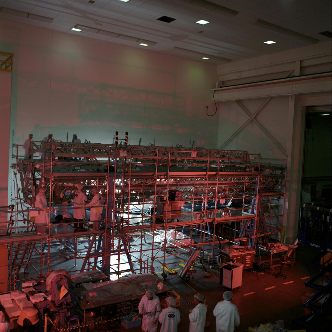
This image shows the Integrated Truss Assembly S-1 (S-One), the Starboard Side Thermal Radiator Truss, for the International Space Station (ISS) undergoing final construction in the Space Station manufacturing facility at the Marshall Space Flight Center. The S1 truss provides structural support for the orbiting research facility's radiator panels, which use ammonia to cool the Station's complex power system. Delivered and installed by the STS-112 mission, the S1 truss, attached to the S0 (S Zero) truss installed by the previous STS-110 mission, flows 637 pounds of anhydrous ammonia through three heat rejection radiators. The truss is 45-feet long, 15-feet wide, 10-feet tall, and weighs approximately 32,000 pounds. Manufactured by the Boeing Company in Huntington Beach, California, the truss primary structure was transferred to the Marshall Space Flight Center in February 1999 for hardware installations and manufacturing acceptance testing.

CAPE CANAVERAL, Fla. – Inside a laboratory in the Space Station Processing Facility at NASA's Kennedy Space Center in Florida, Ray Polniak, a quality assurance specialist with Dynamac, prepares vials for the Crystal Protein Growth 2 experiment for an acceptance leak test. Polniak is a consultant for the Center for Advancement of Science is Space, or CASIS. The experiment is one of many that will be delivered to the International Space Station on the SpaceX-4 commercial cargo resupply mission. Kennedy's ISS Ground Processing and Research Project Office is providing the necessary laboratories, equipment, supplies and consumables for 61 principal investigators, including 17 from other countries, as they prepare their science experiments for flight. The SpaceX-4 flight is targeted to launch in September 2014. Photo credit: NASA/Dimitri Gerondidakis

CAPE CANAVERAL, Fla. – Inside a laboratory in the Space Station Processing Facility at NASA's Kennedy Space Center in Florida, April Spinale, a payload integration specialist with Bionetics, fills vials with clear water during an acceptance leak test on the hardware for the Protein Crystal Growth 2 experiment. To her left is Ray Polniak, a quality assurance specialist with Dynamac. They are both consultants for the Center for Advancement of Science in Space, or CASIS. The experiment is one of many that will be delivered to the International Space Station on the SpaceX-4 commercial cargo resupply mission. Kennedy's ISS Ground Processing and Research Project Office is providing the necessary laboratories, equipment, supplies and consumables for 61 principal investigators, including 17 from other countries, as they prepare their science experiments for flight. The SpaceX-4 flight is targeted to launch in September 2014. Photo credit: NASA/Dimitri Gerondidakis
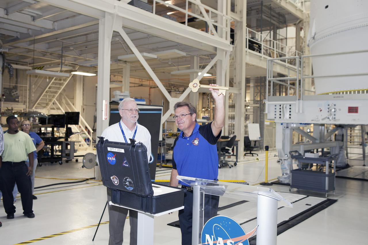
CAPE CANAVERAL, Fla. – During a ceremony inside the Neil Armstrong Operations and Checkout Building high bay at NASA's Kennedy Space Center in Florida, Jules Schneider, Lockheed Martin Orion Production Operations manager, holds the key to symbolically turn over the Orion spacecraft for Exploration Flight Test-1 to Ground Operations. Waiting to accept the key is Blake Hale, Lockheed Martin Ground Operations manager. Orion is the exploration spacecraft designed to carry astronauts to destinations not yet explored by humans, including an asteroid and Mars. It will have emergency abort capability, sustain the crew during space travel and provide safe re-entry from deep space return velocities. The first unpiloted test flight of the Orion is scheduled to launch atop a United Launch Alliance Delta IV Heavy rocket from Cape Canaveral Air Force Station in Florida in December to an altitude of 3,600 miles above the Earth's surface. The two-orbit, four-hour flight test will help engineers evaluate the systems critical to crew safety including the heat shield, parachute system and launch abort system. For more information, visit http://www.nasa.gov/orion. Photo credit: NASA/Daniel Casper
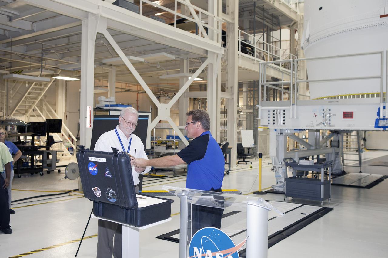
CAPE CANAVERAL, Fla. – During a ceremony inside the Neil Armstrong Operations and Checkout Building high bay at NASA's Kennedy Space Center in Florida, Jules Schneider, at right, Lockheed Martin Orion Production Operations manager, presents the key to symbolically turn over the Orion spacecraft for Exploration Flight Test-1 to Ground Operations. Accepting the key is Blake Hale, Lockheed Martin Ground Operations manager. Orion is the exploration spacecraft designed to carry astronauts to destinations not yet explored by humans, including an asteroid and Mars. It will have emergency abort capability, sustain the crew during space travel and provide safe re-entry from deep space return velocities. The first unpiloted test flight of the Orion is scheduled to launch atop a United Launch Alliance Delta IV Heavy rocket from Cape Canaveral Air Force Station in Florida in December to an altitude of 3,600 miles above the Earth's surface. The two-orbit, four-hour flight test will help engineers evaluate the systems critical to crew safety including the heat shield, parachute system and launch abort system. For more information, visit http://www.nasa.gov/orion. Photo credit: NASA/Daniel Casper

Ronnie Rigney (r), chief of the Propulsion Test Office in the Project Directorate at Stennis Space Center, stands with agency colleagues to receive the prestigious American Institute of Aeronautics and Astronautics George M. Low Space Transportation Award on Sept. 12. Rigney accepted the award on behalf of the NASA and contractor team at Stennis for their support of the Space Shuttle Program that ended last summer. From 1975 to 2009, Stennis Space Center tested every main engine used to power 135 space shuttle missions. Stennis continued to provide flight support services through the end of the Space Shuttle Program in July 2011. The center also supported transition and retirement of shuttle hardware and assets through September 2012. The 2012 award was presented to the space shuttle team 'for excellence in the conception, development, test, operation and retirement of the world's first and only reusable space transportation system.' Joining Rigney for the award ceremony at the 2012 AIAA Conference in Pasadena, Calif., were: (l to r) Allison Zuniga, NASA Headquarters; Michael Griffin, former NASA administrator; Don Noah, Johnson Space Center in Houston; Steve Cash, Marshall Space Flight Center in Huntsville, Ala.; and Pete Nickolenko, Kennedy Space Center in Florida.

Ronnie Rigney (r), chief of the Propulsion Test Office in the Project Directorate at Stennis Space Center, stands with agency colleagues to receive the prestigious American Institute of Aeronautics and Astronautics George M. Low Space Transportation Award on Sept. 12. Rigney accepted the award on behalf of the NASA and contractor team at Stennis for their support of the Space Shuttle Program that ended last summer. From 1975 to 2009, Stennis Space Center tested every main engine used to power 135 space shuttle missions. Stennis continued to provide flight support services through the end of the Space Shuttle Program in July 2011. The center also supported transition and retirement of shuttle hardware and assets through September 2012. The 2012 award was presented to the space shuttle team 'for excellence in the conception, development, test, operation and retirement of the world's first and only reusable space transportation system.' Joining Rigney for the award ceremony at the 2012 AIAA Conference in Pasadena, Calif., were: (l to r) Allison Zuniga, NASA Headquarters; Michael Griffin, former NASA administrator; Don Noah, Johnson Space Center in Houston; Steve Cash, Marshall Space Flight Center in Huntsville, Ala.; and Pete Nickolenko, Kennedy Space Center in Florida.
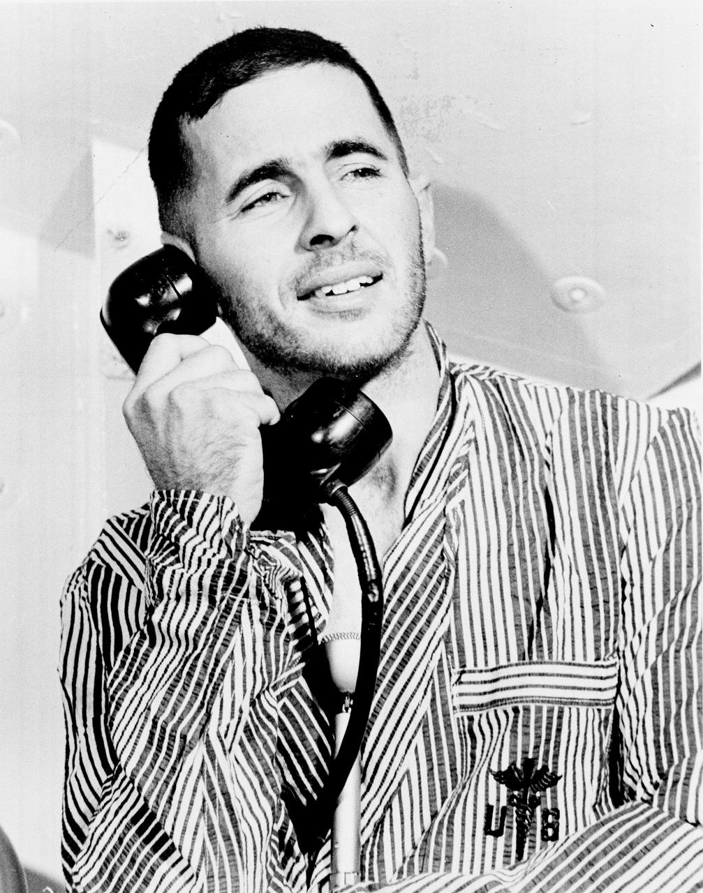
Apollo 8 Astronaut William Anders, Lunar Module (LM) pilot of the first manned Saturn V space flight into Lunar orbit, accepted a phone call from the U.S. President Lyndon B. Johnson prior to launch. Anders, along with astronauts James Lovell, Command Module (CM) pilot, and Frank Borman, commander, launched aboard the Apollo 8 mission on December 21, 1968 and returned safely to Earth on December 27, 1968. The mission achieved operational experience and tested the Apollo command module systems, including communications, tracking, and life-support, in cis-lunar space and lunar orbit, and allowed evaluation of crew performance on a lunar orbiting mission. The crew photographed the lunar surface, both far side and near side, obtaining information on topography and landmarks as well as other scientific information necessary for future Apollo landings. All systems operated within allowable parameters and all objectives of the mission were achieved.
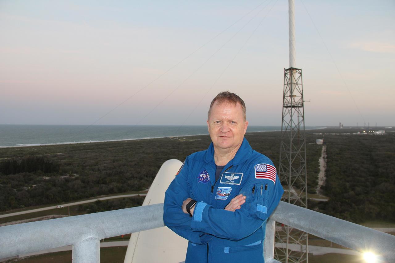
NASA astronaut Eric Boe, one of four astronauts working with the agency’s Commercial Crew Program, checked out the Crew Access Tower at Space Launch Complex 41. Boe is standing on the tower's uppermost level. Visible behind his right arm is the aerodynamic enclosure designed to protect NOAA's Geostationary Operational Environmental Satellite-S during launch – which successfully occurred March 1. To Boe’s left, one of four protective lightning masts is in view. Accompanied by NASA, Boeing and United Launch Alliance engineers, Boe inspected the launch tower to establish whether spotlight and lighting conditions will be acceptable after dark. The survey was required to ensure crew members will have suitable visibility as they prepare to board Boeing’s Starliner spacecraft and launch on missions such as the Crew Flight Test to the International Space Station, targeted for later this year.
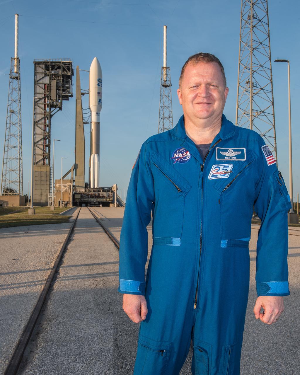
NASA astronaut Eric Boe, one of four astronauts working with the agency’s Commercial Crew Program, checked out the Crew Access Tower at Space Launch Complex 41. The United Launch Alliance (ULA) Atlas V in the background carried NOAA’s Geostationary Operational Environmental Satellite-S into orbit March 1. Later this year, the Atlas V also will carry astronauts to the International Space Station. Along with NASA, Boeing and ULA engineers, Boe inspected the launch pad and tower to establish whether spotlight and lighting conditions will be acceptable after dark. The survey helped to ensure crew members will have suitable visibility as they prepare to board Boeing’s Starliner spacecraft and launch on missions such as the Crew Flight Test to the International Space Station, targeted for later this year.
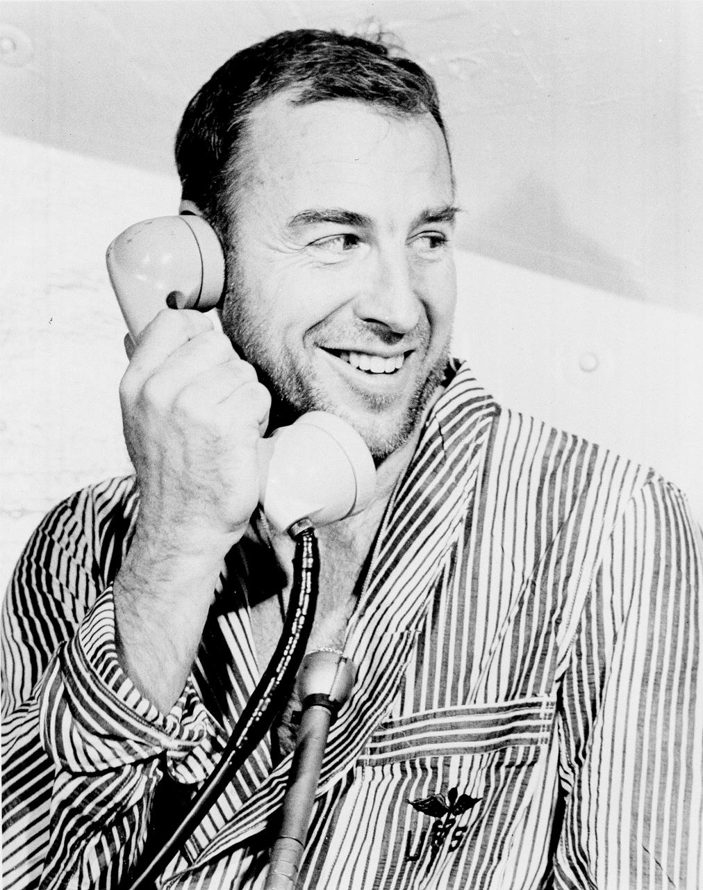
Apollo 8 Astronaut James Lovell, Command Module (CM) pilot of the first manned Saturn V space flight into Lunar orbit, accepted a phone call from the U.S. President Lyndon B. Johnson prior to launch. Lovell, along with astronauts William Anders, Lunar Module (LM) pilot, and Frank Borman, commander, launched aboard the Apollo 8 mission on December 21, 1968 and returned safely to Earth on December 27, 1968. The mission achieved operational experience and tested the Apollo command module systems, including communications, tracking, and life-support, in cis-lunar space and lunar orbit, and allowed evaluation of crew performance on a lunar orbiting mission. The crew photographed the lunar surface, both far side and near side, obtaining information on topography and landmarks as well as other scientific information necessary for future Apollo landings. All systems operated within allowable parameters and all objectives of the mission were achieved.

Apollo 8 Astronaut Frank Borman, commander of the first manned Saturn V space flight into Lunar orbit, accepted a phone call from the U.S. President Lyndon B. Johnson prior to launch. Borman, along with astronauts William Anders, Lunar Module (LM) pilot, and James Lovell, Command Module (CM) pilot, launched aboard the Apollo 8 mission on December 21, 1968 and returned safely to Earth on December 27, 1968. The mission achieved operational experience and tested the Apollo command module systems, including communications, tracking, and life-support, in cis-lunar space and lunar orbit, and allowed evaluation of crew performance on a lunar orbiting mission. The crew photographed the lunar surface, both far side and near side, obtaining information on topography and landmarks as well as other scientific information necessary for future Apollo landings. All systems operated within allowable parameters and all objectives of the mission were achieved.
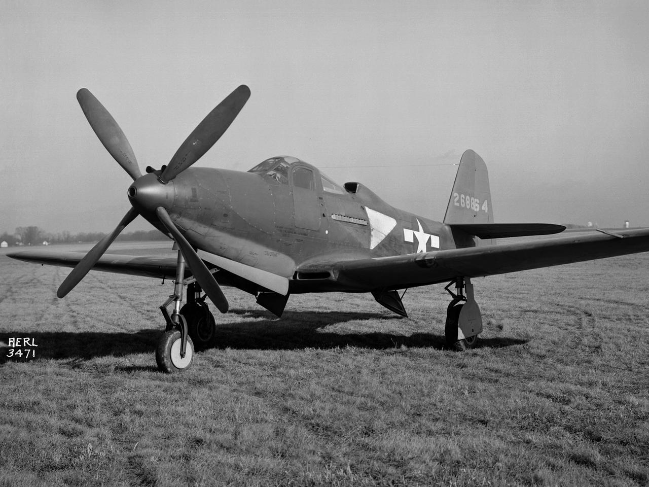
The Army Air Forces lent the National Advisory Committee for Aeronautics (NACA) Aircraft Engine Research Laboratory a Bell P–63A King Cobra in October 1943 to complement the lab's extensive efforts to improve the Allison V–1710 engine. The V–1710-powered P–63A was a single-seat fighter that could reach speeds of 410 miles per hour and an altitude of 43,000 feet. The fighter, first produced in 1942, was an improvement on Bell’s P–39, but persistent performance problems at high altitudes prevented its acceptance by the Air Corps. Instead many of the P–63s were transferred to the Soviet Union. Almost every test facility at the NACA’s engine lab was used to study the Allison V–1710 engine and its supercharger during World War II. Researchers were able to improve the efficiency, capacity and pressure ratio of the supercharger. They found that improved cooling significantly reduced engine knock in the fuel. Once the researchers were satisfied with their improvements, the new supercharger and cooling components were installed on the P–63A. The Flight Research Division first established the aircraft’s normal flight performance parameters such as speed at various altitudes, rate of climb, and peak altitude. Ensuing flights established the performance parameters of the new configuration in order to determine the improved performance. The program increased V–1710’s horsepower from 1650 to 2250.
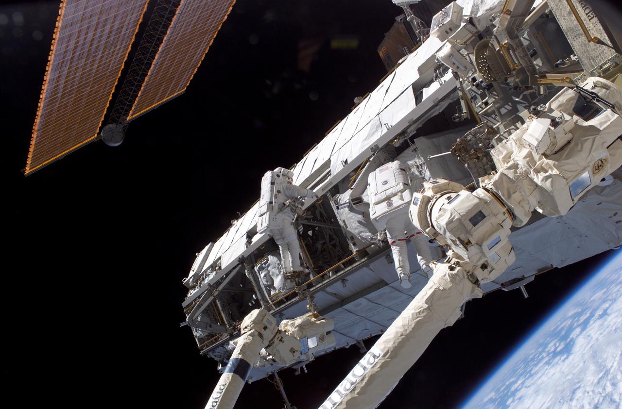
Astronauts Piers J. Sellers (left ) and David A. Wolf work on the newly installed Starboard One (S1) truss to the International Space Station (ISS) during the STS-112 mission. The primary payloads of this mission, ISS Assembly Mission 9A, were the Integrated Truss Assembly S1 (S One), the starboard side thermal radiator truss, and the Crew Equipment Translation Aid (CETA) cart to the ISS. The S1 truss provides structural support for the orbiting research facility's radiator panels, which use ammonia to cool the Station's complex power system. The S1 truss was attached to the S0 (S Zero) truss, which was launched on April 8, 2002 aboard the STS-110, and flows 637 pounds of anhydrous ammonia through three heat-rejection radiators. The truss is 45-feet long, 15-feet wide, 10-feet tall, and weighs approximately 32,000 pounds. The CETA cart was attached to the Mobil Transporter and will be used by assembly crews on later missions. Manufactured by the Boeing Company in Huntington Beach, California, the truss primary structure was transferred to the Marshall Space Flight Center in February 1999 for hardware installations and manufacturing acceptance testing. The launch of the STS-112 mission occurred on October 7, 2002, and its 11-day mission ended on October 18, 2002.
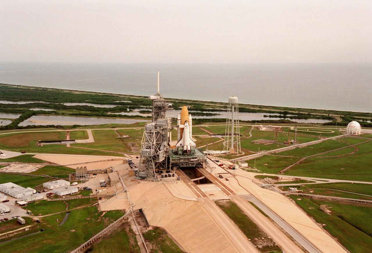
The STS-95 Space Shuttle Discovery sits on the Mobile Launch Platform, still atop the crawler transporter, at Launch Pad 39B. To its left is the Fixed Service Structure that provides access to the orbiter and the Rotating Service Structure. To its right is the elevated water tank, with a capacity of 300,000 gallons. Part of the sound suppression water system, the tank stands 290 feet high on the northeast side of the pad. Water from the tank is released just before ignition of the orbiter's three main engines and twin solid rocket boosters. The entire system reduces the acoustical levels within the orbiter's payload bay to an acceptable 142 decibels. Beyond the orbiter is seen the Atlantic Ocean. While at the launch pad, the orbiter, external tank and solid rocket boosters will undergo final preparations for the launch, scheduled to lift off Oct. 29. The mission includes research payloads such as the Spartan solar-observing deployable spacecraft, the Hubble Space Telescope Orbital Systems Test Platform, the International Extreme Ultraviolet Hitchhiker, as well as the SPACEHAB single module with experiments on space flight and the aging process
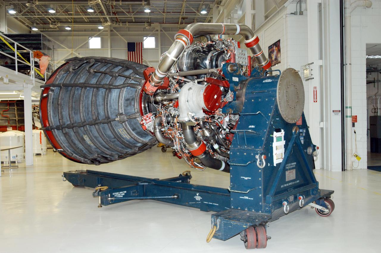
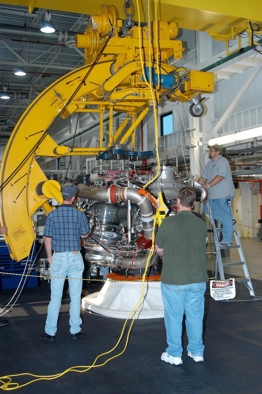
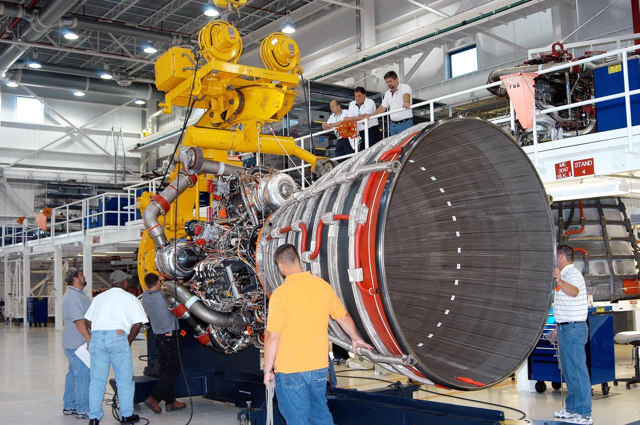
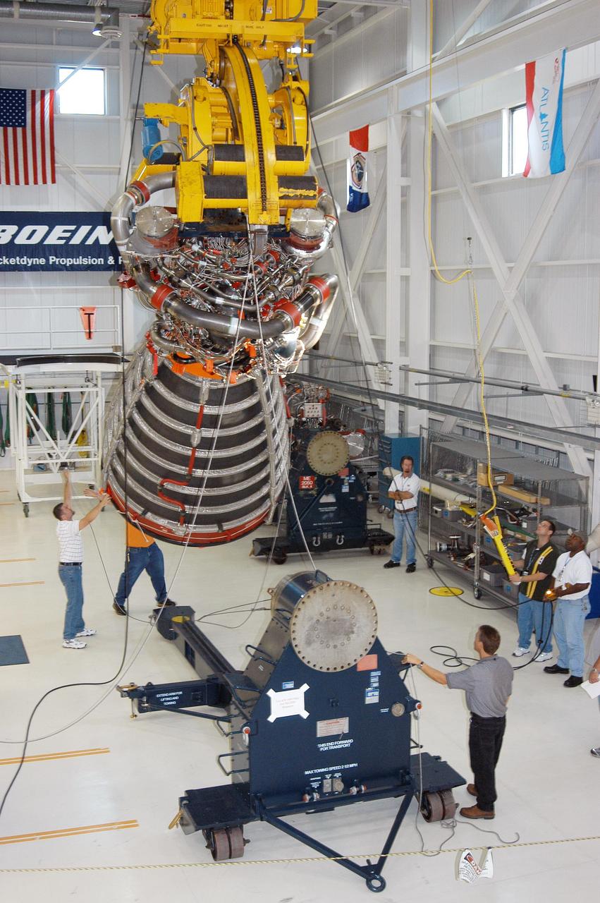
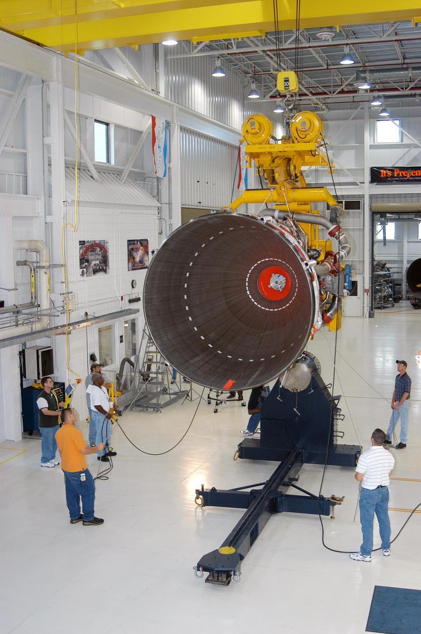
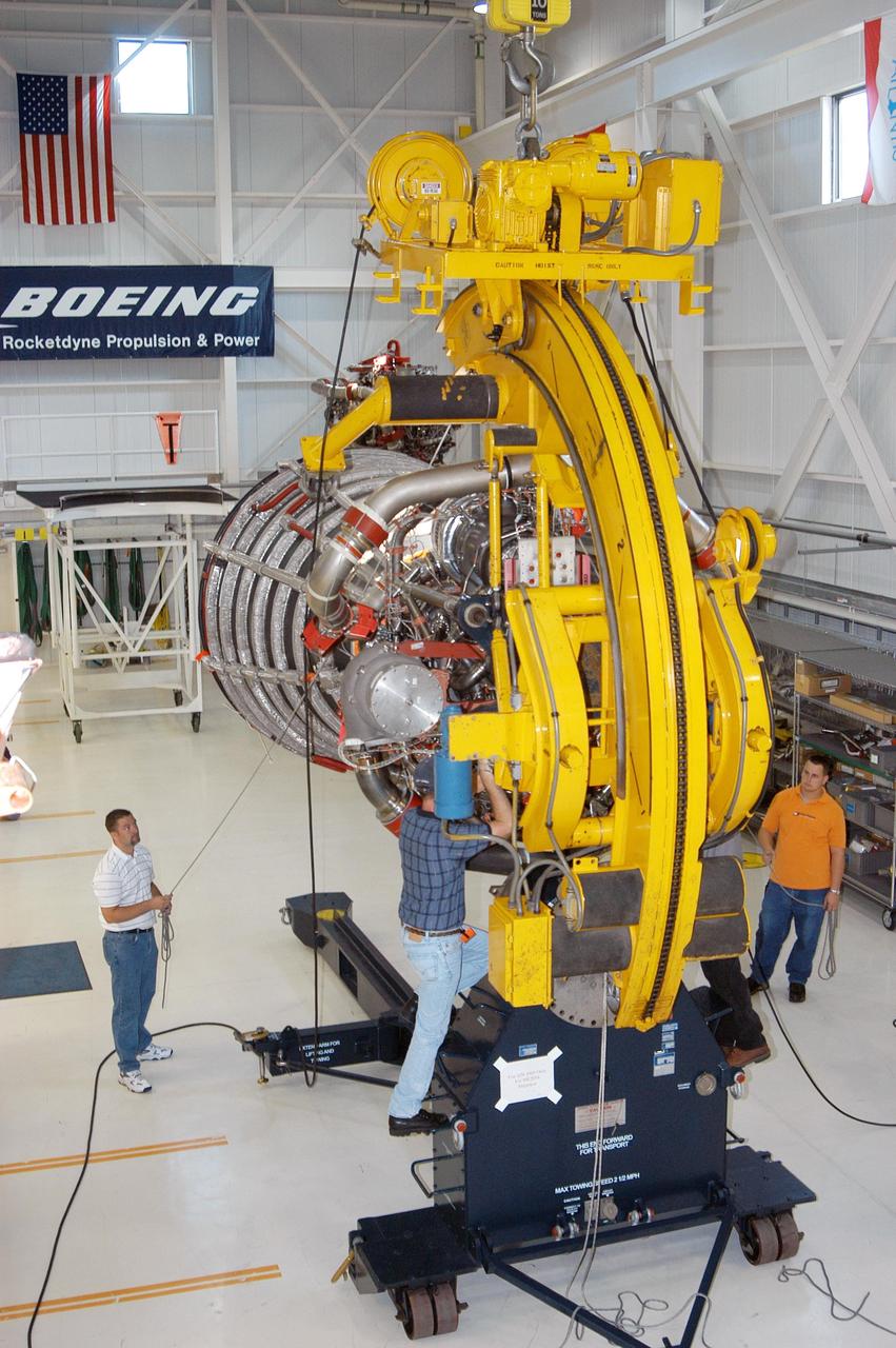
KENNEDY SPACE CENTER, FLA. - In the Space Shuttle Main Engine (SSME) Processing Facility, Boeing-Rocketdyne technicians prepare to move SSME 2058, the first SSME fully assembled at KSC. The engine will be lifted from its vertical work stand into a horizontal position in preparation for shipment to NASA’s Stennis Space Center in Mississippi to undergo a hot fire acceptance test. It is the first of five engines to be fully assembled on site to reach the desired number of 15 engines ready for launch at any given time in the Space Shuttle program. A Space Shuttle has three reusable main engines. Each is 14 feet long, weighs about 7,800 pounds, is seven-and-a-half feet in diameter at the end of its nozzle, and generates almost 400,000 pounds of thrust. Historically, SSMEs were assembled in Canoga Park, Calif., with post-flight inspections performed at KSC. Both functions were consolidated in February 2002. The Rocketdyne Propulsion and Power division of The Boeing Co. manufactures the engines for NASA.
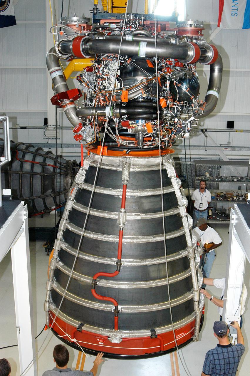
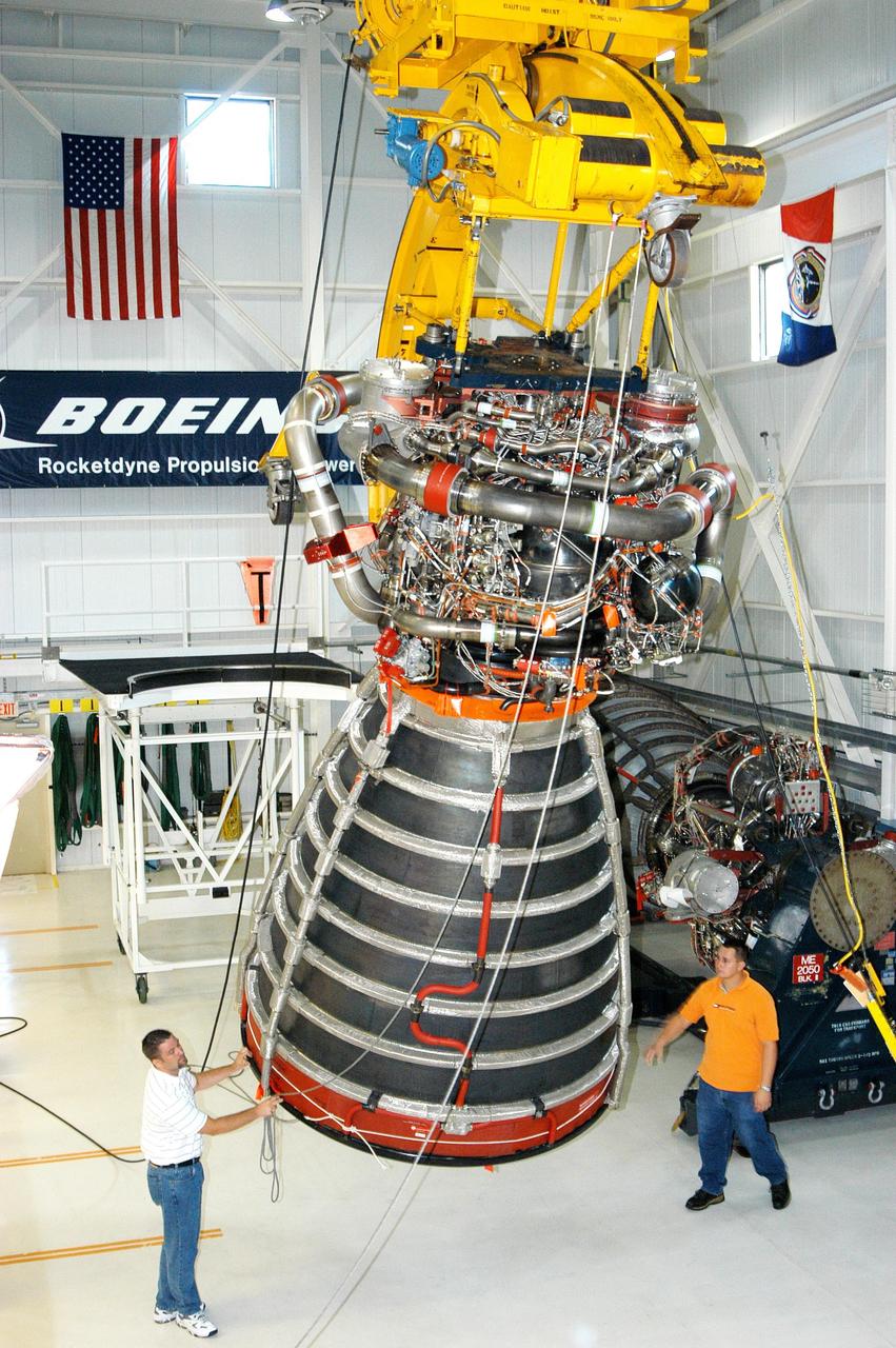
KENNEDY SPACE CENTER, FLA. - In the Space Shuttle Main Engine (SSME) Processing Facility, Boeing-Rocketdyne technicians lift SSME 2058, the first SSME fully assembled at KSC. The engine is being lifted from its vertical work stand into a horizontal position in preparation for shipment to NASA’s Stennis Space Center in Mississippi to undergo a hot fire acceptance test. It is the first of five engines to be fully assembled on site to reach the desired number of 15 engines ready for launch at any given time in the Space Shuttle program. A Space Shuttle has three reusable main engines. Each is 14 feet long, weighs about 7,800 pounds, is seven-and-a-half feet in diameter at the end of its nozzle, and generates almost 400,000 pounds of thrust. Historically, SSMEs were assembled in Canoga Park, Calif., with post-flight inspections performed at KSC. Both functions were consolidated in February 2002. The Rocketdyne Propulsion and Power division of The Boeing Co. manufactures the engines for NASA.
KENNEDY SPACE CENTER, FLA. - In the Space Shuttle Main Engine (SSME) Processing Facility, Boeing-Rocketdyne quality inspector Nick Grimm (center) monitors the work of technicians on his team as they lower SSME 2058, the first SSME fully assembled at KSC, onto an engine stand. The engine is being placed into a horizontal position in preparation for shipment to NASA’s Stennis Space Center in Mississippi to undergo a hot fire acceptance test. It is the first of five engines to be fully assembled on site to reach the desired number of 15 engines ready for launch at any given time in the Space Shuttle program. A Space Shuttle has three reusable main engines. Each is 14 feet long, weighs about 7,800 pounds, is seven-and-a-half feet in diameter at the end of its nozzle, and generates almost 400,000 pounds of thrust. Historically, SSMEs were assembled in Canoga Park, Calif., with post-flight inspections performed at KSC. Both functions were consolidated in February 2002. The Rocketdyne Propulsion and Power division of The Boeing Co. manufactures the engines for NASA.
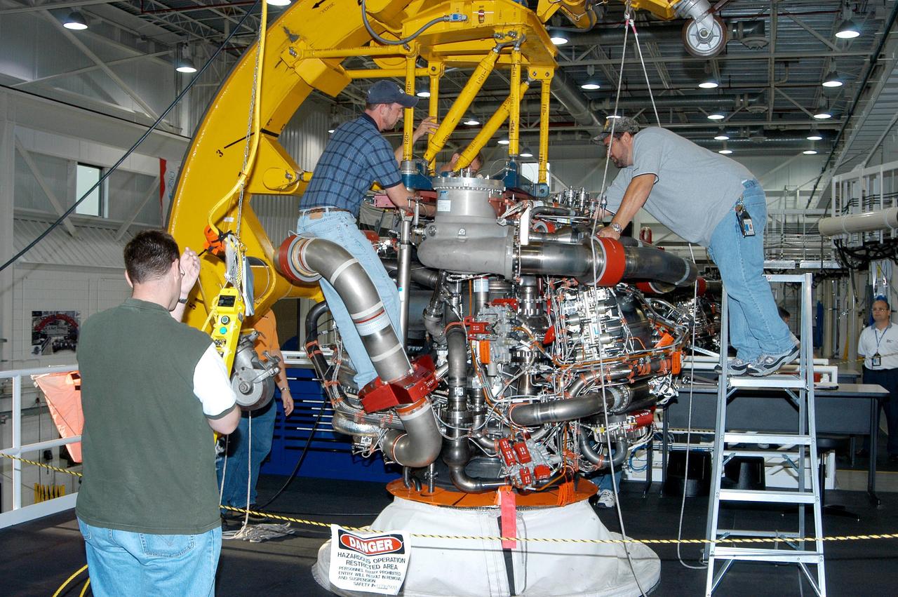
KENNEDY SPACE CENTER, FLA. - In the Space Shuttle Main Engine (SSME) Processing Facility, Boeing-Rocketdyne technicians prepare to move SSME 2058, the first SSME fully assembled at KSC. Move conductor Bob Brackett (on ladder) and technicians secure a sling around the engine under the direction of crane operator Joe Ferrante (left). The engine will be lifted from its vertical work stand into a horizontal position in preparation for shipment to NASA’s Stennis Space Center in Mississippi to undergo a hot fire acceptance test. It is the first of five engines to be fully assembled on site to reach the desired number of 15 engines ready for launch at any given time in the Space Shuttle program. A Space Shuttle has three reusable main engines. Each is 14 feet long, weighs about 7,800 pounds, is seven-and-a-half feet in diameter at the end of its nozzle, and generates almost 400,000 pounds of thrust. Historically, SSMEs were assembled in Canoga Park, Calif., with post-flight inspections performed at KSC. Both functions were consolidated in February 2002. The Rocketdyne Propulsion and Power division of The Boeing Co. manufactures the engines for NASA.
KENNEDY SPACE CENTER, FLA. - In the Space Shuttle Main Engine (SSME) Processing Facility, Boeing-Rocketdyne technicians prepare to move SSME 2058, the first SSME fully assembled at KSC. Move conductor Bob Brackett (on ladder) supervises the placement of a sling around the engine with the assistance of crane operator Joe Ferrante (center) and a technician. The engine will be lifted from its vertical work stand into a horizontal position in preparation for shipment to NASA’s Stennis Space Center in Mississippi to undergo a hot fire acceptance test. It is the first of five engines to be fully assembled on site to reach the desired number of 15 engines ready for launch at any given time in the Space Shuttle program. A Space Shuttle has three reusable main engines. Each is 14 feet long, weighs about 7,800 pounds, is seven-and-a-half feet in diameter at the end of its nozzle, and generates almost 400,000 pounds of thrust. Historically, SSMEs were assembled in Canoga Park, Calif., with post-flight inspections performed at KSC. Both functions were consolidated in February 2002. The Rocketdyne Propulsion and Power division of The Boeing Co. manufactures the engines for NASA.
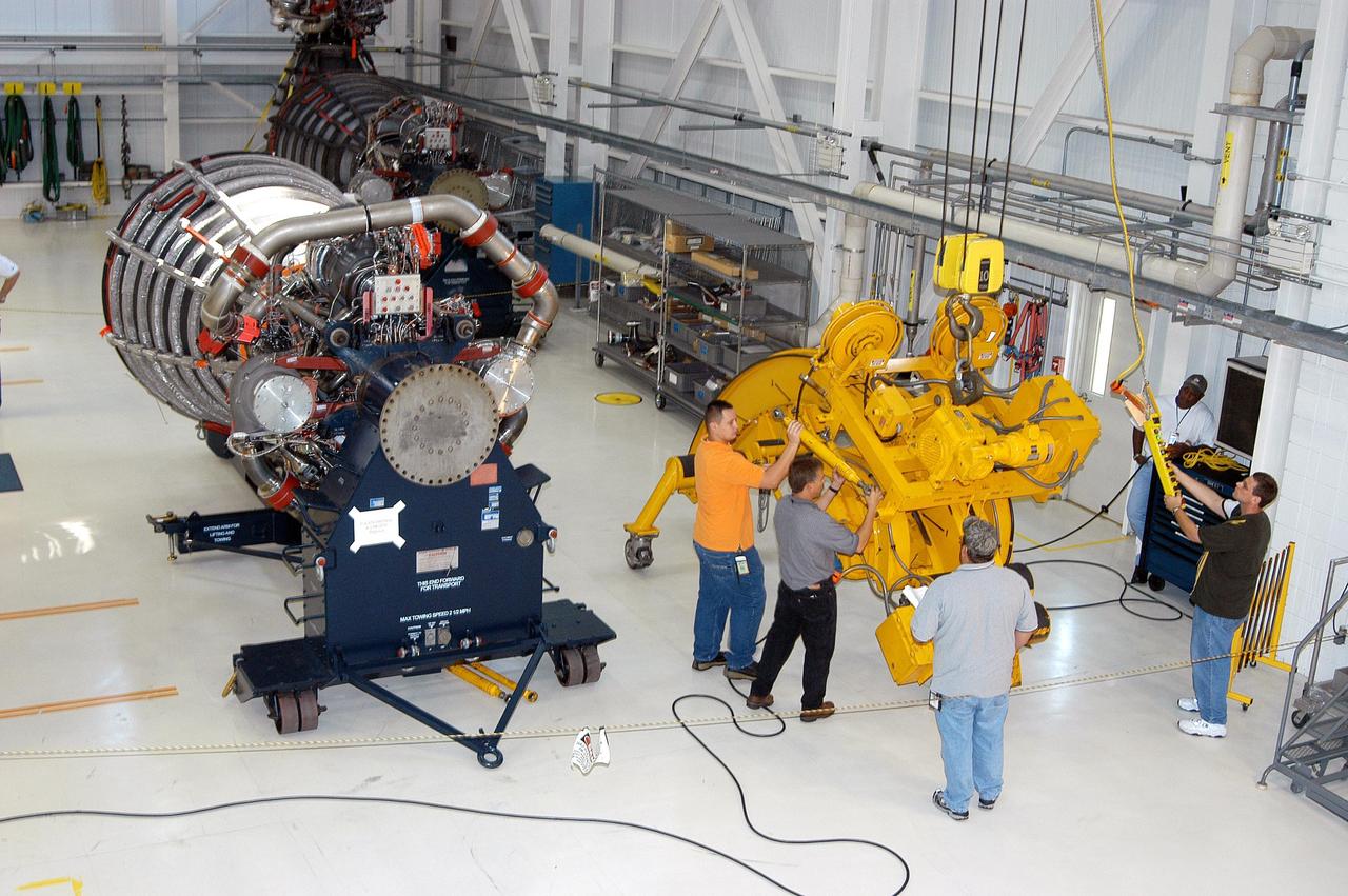
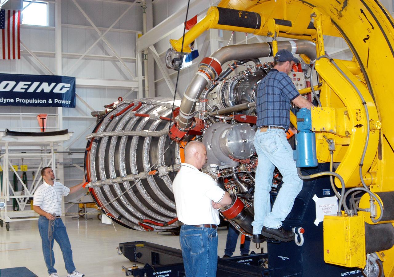
KENNEDY SPACE CENTER, FLA. - In the Space Shuttle Main Engine (SSME) Processing Facility, Boeing-Rocketdyne move conductor Bob Brackett (center) oversees the work of technicians on his team as they remove the crane used to lift SSME 2058, the first SSME fully assembled at KSC, from its vertical work stand. The engine has been placed into a horizontal position in preparation for shipment to NASA’s Stennis Space Center in Mississippi to undergo a hot fire acceptance test. It is the first of five engines to be fully assembled on site to reach the desired number of 15 engines ready for launch at any given time in the Space Shuttle program. A Space Shuttle has three reusable main engines. Each is 14 feet long, weighs about 7,800 pounds, is seven-and-a-half feet in diameter at the end of its nozzle, and generates almost 400,000 pounds of thrust. Historically, SSMEs were assembled in Canoga Park, Calif., with post-flight inspections performed at KSC. Both functions were consolidated in February 2002. The Rocketdyne Propulsion and Power division of The Boeing Co. manufactures the engines for NASA.
KENNEDY SPACE CENTER, FLA. - In the Space Shuttle Main Engine (SSME) Processing Facility, Boeing-Rocketdyne technicians steady SSME 2058, the first SSME fully assembled at KSC. The engine is being lifted from its vertical work stand into a horizontal position in preparation for shipment to NASA’s Stennis Space Center in Mississippi to undergo a hot fire acceptance test. It is the first of five engines to be fully assembled on site to reach the desired number of 15 engines ready for launch at any given time in the Space Shuttle program. A Space Shuttle has three reusable main engines. Each is 14 feet long, weighs about 7,800 pounds, is seven-and-a-half feet in diameter at the end of its nozzle, and generates almost 400,000 pounds of thrust. Historically, SSMEs were assembled in Canoga Park, Calif., with post-flight inspections performed at KSC. Both functions were consolidated in February 2002. The Rocketdyne Propulsion and Power division of The Boeing Co. manufactures the engines for NASA.
KENNEDY SPACE CENTER, FLA. - In the Space Shuttle Main Engine (SSME) Processing Facility, Boeing-Rocketdyne move conductor Bob Brackett (left) oversees the work of technicians on his team as they secure SSME 2058, the first SSME fully assembled at KSC, onto an engine stand. The engine is being placed into a horizontal position in preparation for shipment to NASA’s Stennis Space Center in Mississippi to undergo a hot fire acceptance test. It is the first of five engines to be fully assembled on site to reach the desired number of 15 engines ready for launch at any given time in the Space Shuttle program. A Space Shuttle has three reusable main engines. Each is 14 feet long, weighs about 7,800 pounds, is seven-and-a-half feet in diameter at the end of its nozzle, and generates almost 400,000 pounds of thrust. Historically, SSMEs were assembled in Canoga Park, Calif., with post-flight inspections performed at KSC. Both functions were consolidated in February 2002. The Rocketdyne Propulsion and Power division of The Boeing Co. manufactures the engines for NASA.
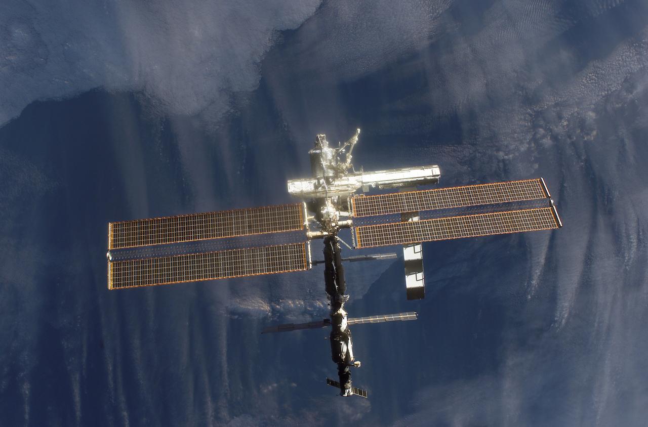
This image of the International Space Station (ISS) was photographed by one of the crewmembers of the STS-112 mission following separation from the Space Shuttle Orbiter Atlantis as the orbiter pulled away from the ISS. The newly added S1 truss is visible in the center frame. The primary payloads of this mission, International Space Station Assembly Mission 9A, were the Integrated Truss Assembly S-1 (S-One), the Starboard Side Thermal Radiator Truss,and the Crew Equipment Translation Aid (CETA) cart to the ISS. The S1 truss provides structural support for the orbiting research facility's radiator panels, which use ammonia to cool the Station's complex power system. The S1 truss was attached to the S0 (S Zero) truss, which was launched on April 8, 2002 aboard the STS-110, and flows 637 pounds of anhydrous ammonia through three heat rejection radiators. The truss is 45-feet long, 15-feet wide, 10-feet tall, and weighs approximately 32,000 pounds. The CETA cart was attached to the Mobil Transporter and will be used by assembly crews on later missions. Manufactured by the Boeing Company in Huntington Beach, California, the truss primary structure was transferred to the Marshall Space Flight Center in February 1999 for hardware installations and manufacturing acceptance testing. The launch of the STS-112 mission occurred on October 7, 2002, and its 11-day mission ended on October 18, 2002.
KENNEDY SPACE CENTER, FLA. - In the Space Shuttle Main Engine (SSME) Processing Facility, Boeing-Rocketdyne crane operator Joe Ferrante (second from right) lifts SSME 2058, the first SSME fully assembled at KSC, with the assistance of other technicians on his team. The engine is being lifted from its vertical work stand into a horizontal position in preparation for shipment to NASA’s Stennis Space Center in Mississippi to undergo a hot fire acceptance test. It is the first of five engines to be fully assembled on site to reach the desired number of 15 engines ready for launch at any given time in the Space Shuttle program. A Space Shuttle has three reusable main engines. Each is 14 feet long, weighs about 7,800 pounds, is seven-and-a-half feet in diameter at the end of its nozzle, and generates almost 400,000 pounds of thrust. Historically, SSMEs were assembled in Canoga Park, Calif., with post-flight inspections performed at KSC. Both functions were consolidated in February 2002. The Rocketdyne Propulsion and Power division of The Boeing Co. manufactures the engines for NASA.
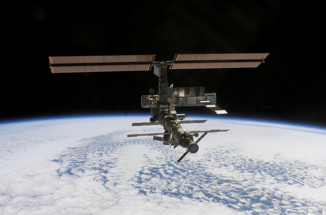
This image of the International Space Station (ISS) was photographed by one of the crewmembers of the STS-112 mission following separation from the Space Shuttle Orbiter Atlantis as the orbiter pulled away from the ISS. The primary payloads of this mission, International Space Station Assembly Mission 9A, were the Integrated Truss Assembly S1 (S-One), the Starboard Side Thermal Radiator Truss, and the Crew Equipment Translation Aid (CETA) cart to the ISS. The S1 truss provides structural support for the orbiting research facility's radiator panels, which use ammonia to cool the Station's complex power system. The S1 truss was attached to the S0 (S Zero) truss, which was launched on April 8, 2002 aboard the STS-110, and flows 637 pounds of anhydrous ammonia through three heat-rejection radiators. The truss is 45-feet long, 15-feet wide, 10-feet tall, and weighs approximately 32,000 pounds. The CETA cart was attached to the Mobil Transporter and will be used by assembly crews on later missions. Manufactured by the Boeing Company in Huntington Beach, California, the truss primary structure was transferred to the Marshall Space Flight Center in February 1999 for hardware installations and manufacturing acceptance testing. The launch of the STS-112 mission occurred on October 7, 2002, and its 11-day mission ended on October 18, 2002.
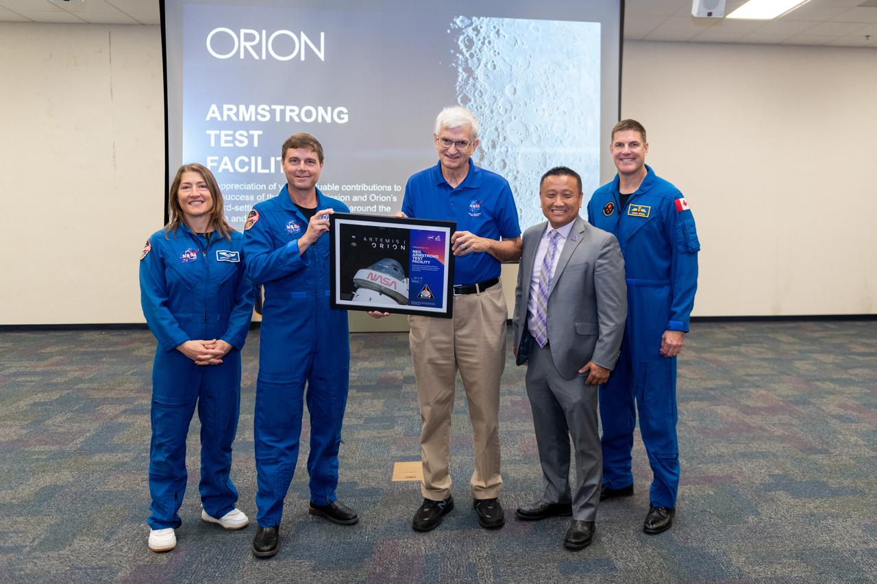
Employees meet three of the four astronauts who will venture around the Moon on Artemis II, the first crewed flight paving the way for future lunar surface missions. Commander Reid Wiseman and Mission Specialists Christina Koch and Jeremy Hansen will be on hand to discuss their upcoming mission and participate in a Question and Answer session with employees afterward. Hansen is an astronaut with the Canadian Space Agency. Victor Glover, the pilot and fourth crew member, will not be present. Awards were given to employees that participated in Orion for Artemis I on September 11, 2024. General David Stringer accepts an award. The crew of four astronauts will lift off on an approximately 10-day mission from Launch Complex 39B at NASA’s Kennedy Space Center in Florida, blazing beyond Earth’s grasp atop the agency’s mega Moon rocket. The crew will check out Orion’s systems and perform a targeting demonstration test relatively close to Earth before venturing around the Moon. Photo Credit: (NASA/Sara Lowthian-Hanna)
KENNEDY SPACE CENTER, FLA. - In the Space Shuttle Main Engine (SSME) Processing Facility, Boeing-Rocketdyne crane operator Joe Ferrante (left) lowers SSME 2058, the first SSME fully assembled at KSC, onto an engine stand with the assistance of other technicians on his team. The engine is being moved from its vertical work stand into a horizontal position in preparation for shipment to NASA’s Stennis Space Center in Mississippi to undergo a hot fire acceptance test. It is the first of five engines to be fully assembled on site to reach the desired number of 15 engines ready for launch at any given time in the Space Shuttle program. A Space Shuttle has three reusable main engines. Each is 14 feet long, weighs about 7,800 pounds, is seven-and-a-half feet in diameter at the end of its nozzle, and generates almost 400,000 pounds of thrust. Historically, SSMEs were assembled in Canoga Park, Calif., with post-flight inspections performed at KSC. Both functions were consolidated in February 2002. The Rocketdyne Propulsion and Power division of The Boeing Co. manufactures the engines for NASA.
KENNEDY SPACE CENTER, FLA. - In the Space Shuttle Main Engine (SSME) Processing Facility, Boeing-Rocketdyne technicians lower SSME 2058, the first SSME fully assembled at KSC, onto an engine stand. The engine is being moved from its vertical work stand into a horizontal position in preparation for shipment to NASA’s Stennis Space Center in Mississippi to undergo a hot fire acceptance test. It is the first of five engines to be fully assembled on site to reach the desired number of 15 engines ready for launch at any given time in the Space Shuttle program. A Space Shuttle has three reusable main engines. Each is 14 feet long, weighs about 7,800 pounds, is seven-and-a-half feet in diameter at the end of its nozzle, and generates almost 400,000 pounds of thrust. Historically, SSMEs were assembled in Canoga Park, Calif., with post-flight inspections performed at KSC. Both functions were consolidated in February 2002. The Rocketdyne Propulsion and Power division of The Boeing Co. manufactures the engines for NASA.
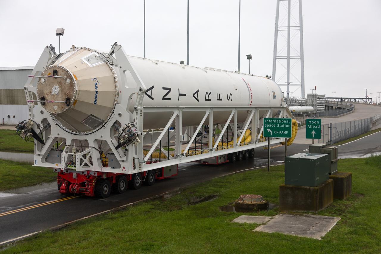
Orbital ATK’s Antares first stage with the new engines is rolled from NASA Wallops Flight Facility’s Horizontal Integration Facility to Virginia Space’s Mid-Atlantic Regional Spaceport Pad-0A on May 12, 2016, in preparation for the upcoming stage test in the next few weeks. The team will continue to work meticulously as they begin final integration and check outs on the pad and several readiness reviews prior to the test. The window for the stage test will be over multiple days to ensure technical and weather conditions are acceptable. Credit: NASA's Wallops Flight Facility/Allison Stancil <b><a href="http://www.nasa.gov/audience/formedia/features/MP_Photo_Guidelines.html" rel="nofollow">NASA image use policy.</a></b> <b><a href="http://www.nasa.gov/centers/goddard/home/index.html" rel="nofollow">NASA Goddard Space Flight Center</a></b> enables NASA’s mission through four scientific endeavors: Earth Science, Heliophysics, Solar System Exploration, and Astrophysics. Goddard plays a leading role in NASA’s accomplishments by contributing compelling scientific knowledge to advance the Agency’s mission. <b>Follow us on <a href="http://twitter.com/NASAGoddardPix" rel="nofollow">Twitter</a></b> <b>Like us on <a href="http://www.facebook.com/pages/Greenbelt-MD/NASA-Goddard/395013845897?ref=tsd" rel="nofollow">Facebook</a></b> <b>Find us on <a href="http://instagrid.me/nasagoddard/?vm=grid" rel="nofollow">Instagram</a></b>
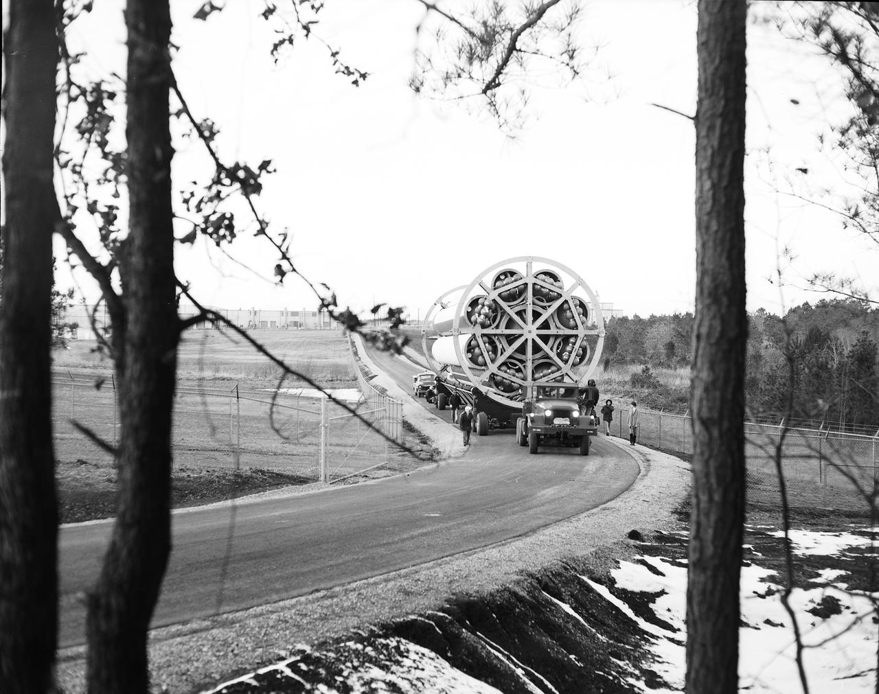
This photograph shows the Saturn-I first stage (S-1 stage) being transported to the test stand for a static test firing at the Marshall Space Flight Center. Soon after NASA began operations in October 1958, it was evident that sending people and substantial equipment beyond the Earth's gravitational field would require launch vehicles with weight-lifting capabilities far beyond any developed to that time. In early 1959, NASA accepted the proposal of Dr. Wernher von Braun for a multistage rocket, with a number of engines clustered in one or more of the stages to provide a large total thrust. The initiation of the Saturn launch vehicle program ultimately led to the study and preliminary plarning of many different configurations and resulted in production of three Saturn launch vehicles, the Saturn-I, Saturn I-B, and Saturn V. The Saturn family of launch vehicles began with the Saturn-I, a two-stage vehicle originally designated C-1. The research and development program was planned in two phases, or blocks: one for first stage development (Block I) and the second for both first and second stage development (Block-II). Saturn I had a low-earth-orbit payload capability of approximately 25,000 pounds. The design of the first stage (S-1 stage) used a cluster of propellant tanks containing liquid oxygen (LOX) and kerosene (RP-1), and eight H-1 engines, yielding a total thrust of 1,500,000 pounds. Of the ten Saturn-Is planned, the first eight were designed and built at the Marshall Space Flight Center, and the remaining two were built by the Chrysler Corporation.
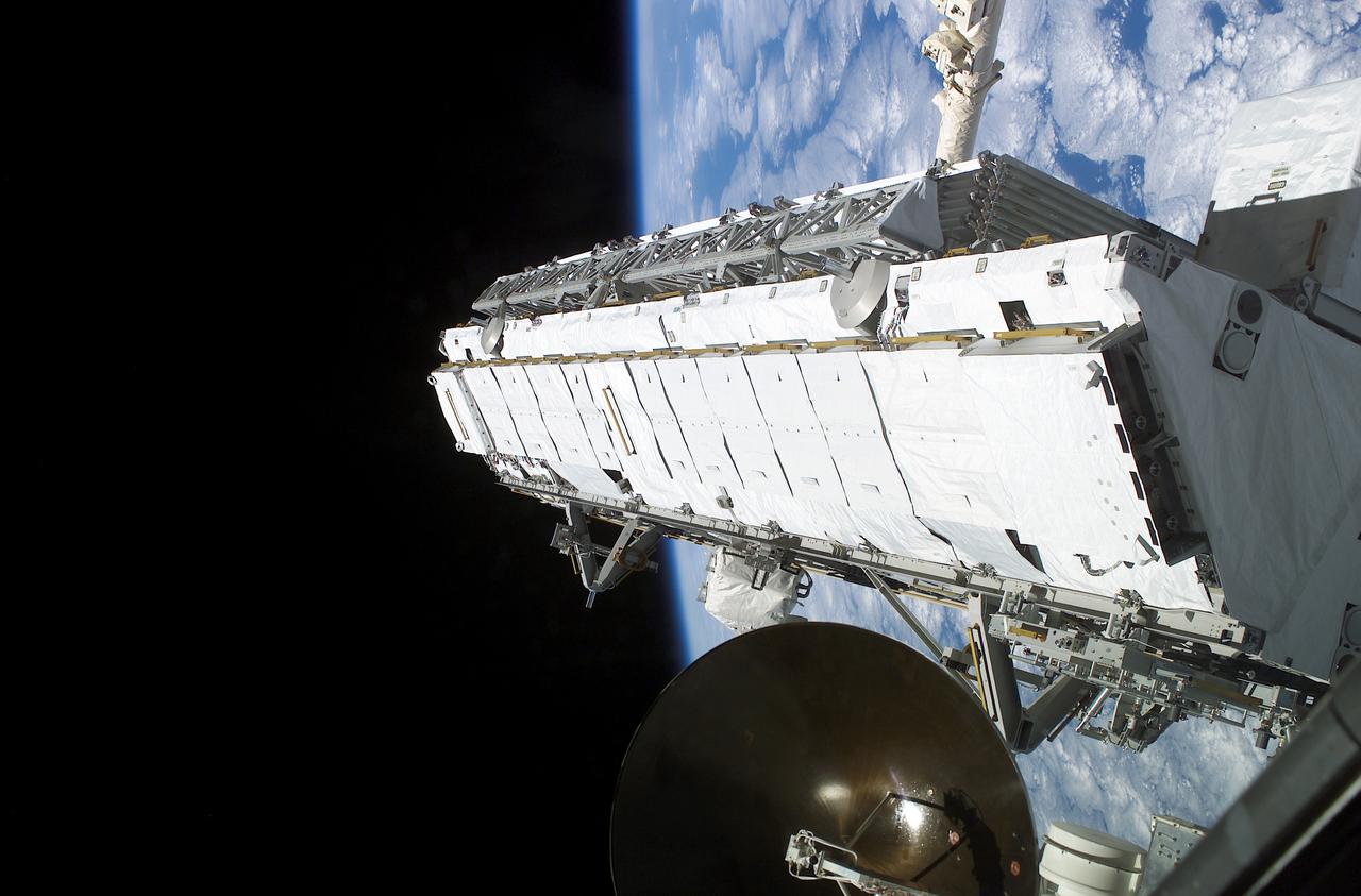
Being attached to the Canadarm2 on the International Space Station (ISS), the Remote Manipulator System arm built by the Canadian Space Agency, the Integrated Truss Assembly (S1) Truss is suspended over the Space Shuttle Orbiter Atlantis' cargo bay. Astronauts Sandra H. Magnus, STS-112 mission specialist, and Peggy A. Whitson, Expedition Five flight engineer, used the Canadarm2 from inside the Destiny laboratory on the ISS to lift the S1 truss out of the orbiter's cargo bay and move it into position prior to its installation on the ISS. The primary payloads of this mission, ISS Assembly Mission 9A, were the Integrated Truss Assembly S1 (S One), the starboard side thermal radiator truss, and the Crew Equipment Translation Aid (CETA) cart to the ISS. The S1 truss provides structural support for the orbiting research facility's radiator panels, which use ammonia to cool the Station's complex power system. The S1 truss was attached to the S0 (S Zero) truss, which was launched on April 8, 2002 aboard the STS-110, and flows 637 pounds of anhydrous ammonia through three heat-rejection radiators. The truss is 45-feet long, 15-feet wide, 10-feet tall, and weighs approximately 32,000 pounds. The CETA cart was attached to the Mobil Transporter and will be used by assembly crews on later missions. Manufactured by the Boeing Company in Huntington Beach, California, the truss primary structure was transferred to the Marshall Space Flight Center in February 1999 for hardware installations and manufacturing acceptance testing. The launch of the STS-112 mission occurred on October 7, 2002, and its 11-day mission ended on October 18, 2002.
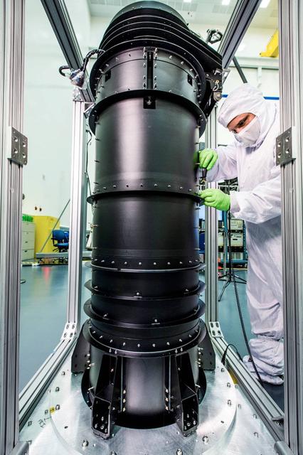
Building a space telescope to see the light from the earliest stars of our universe is a pretty complex task. Although much of the attention goes to instruments and the giant mirrors on NASA's James Webb Space Telescope, there are other components that have big jobs to do and that required imagination, engineering, and innovation to become a reality. For example, engineers working on the Webb telescope have to think of everything from keeping instruments from overheating or freezing, to packing up the Webb, which is as big as a tennis court, to fit inside the rocket that will take it to space. Those are two areas where the "DTA" or Deployable Tower Assembly (DTA) plays a major role. The DTA looks like a big black pipe and is made out of graphite-epoxy composite material to ensure stability and strength with extreme changes in temperature like those encountered in space. When fully deployed, the DTA reaches ten feet in length. The DTA interfaces and supports the spacecraft and the telescope structures. It features two large nested telescoping tubes, connected by a mechanized lead screw. It is a deployable structure that is both very light and extremely strong and stable. The Webb telescope’s secondary mirror support structure and DTA contribute to how the telescope and instruments fit into the rocket fairing in preparation for launch. The DTA allows the Webb to be short enough when stowed to fit in the rocket fairing with an acceptably low center of gravity for launch. Several days after the Webb telescope is launched, the DTA will deploy, or separate, the telescope mirrors and instruments from the spacecraft bus and sunshield. This separation allows the sunshield to unfurl and shade the telescope and instruments from radiant heat and stray light from the sun and Earth. The DTA was designed, built and tested by Astro Aerospace - a Northrop Grumman Company, in Carpinteria, California. The James Webb Space Telescope is the scientific successor to NASA's Hubble Space Telescope. It will be the most powerful space telescope ever built. The Webb telescope is an international project led by NASA with its partners, the European Space Agency and the Canadian Space Agency. For more information about the Webb telescope, visit: <a href="http://www.nasa.gov/webb" rel="nofollow">www.nasa.gov/webb</a> or jwst.nasa.gov <b><a href="http://www.nasa.gov/audience/formedia/features/MP_Photo_Guidelines.html" rel="nofollow">NASA image use policy.</a></b> <b><a href="http://www.nasa.gov/centers/goddard/home/index.html" rel="nofollow">NASA Goddard Space Flight Center</a></b> enables NASA’s mission through four scientific endeavors: Earth Science, Heliophysics, Solar System Exploration, and Astrophysics. Goddard plays a leading role in NASA’s accomplishments by contributing compelling scientific knowledge to advance the Agency’s mission. <b>Follow us on <a href="http://twitter.com/NASAGoddardPix" rel="nofollow">Twitter</a></b> <b>Like us on <a href="http://www.facebook.com/pages/Greenbelt-MD/NASA-Goddard/395013845897?ref=tsd" rel="nofollow">Facebook</a></b> <b>Find us on <a href="http://instagrid.me/nasagoddard/?vm=grid" rel="nofollow">Instagram</a></b>