Aeronautics Technical Seminar: Nhan Nguyen presents 'NASA Past and Present Research in Adaptive Flight Control and Technology Challenges'
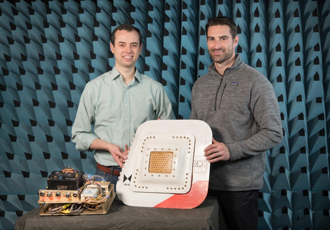
Flight Electronics Payload for Curved Confocal Lightweight Antenna Structures for Aeronautical Communications Technologies, CLAS-ACT, Phased Array Antenna on T-34-C Aircraft Door Flight Curved Confocal Lightweight Antenna Structures for Aeronautical Communications Technologies, CLAS-ACT, Phased Array Antenna Control / Flight Testing
NASA engineer Larry Hudson and Ikhana ground crew member James Smith work on a ground validation test with new fiber optic sensors that led to validation flights on the Ikhana aircraft. NASA Dryden Flight Research Center is evaluating an advanced fiber optic-based sensing technology installed on the wings of NASA's Ikhana aircraft. The fiber optic system measures and displays the shape of the aircraft's wings in flight. There are other potential safety applications for the technology, such as vehicle structural health monitoring. If an aircraft structure can be monitored with sensors and a computer can manipulate flight control surfaces to compensate for stresses on the wings, structural control can be established to prevent situations that might otherwise result in a loss of control.
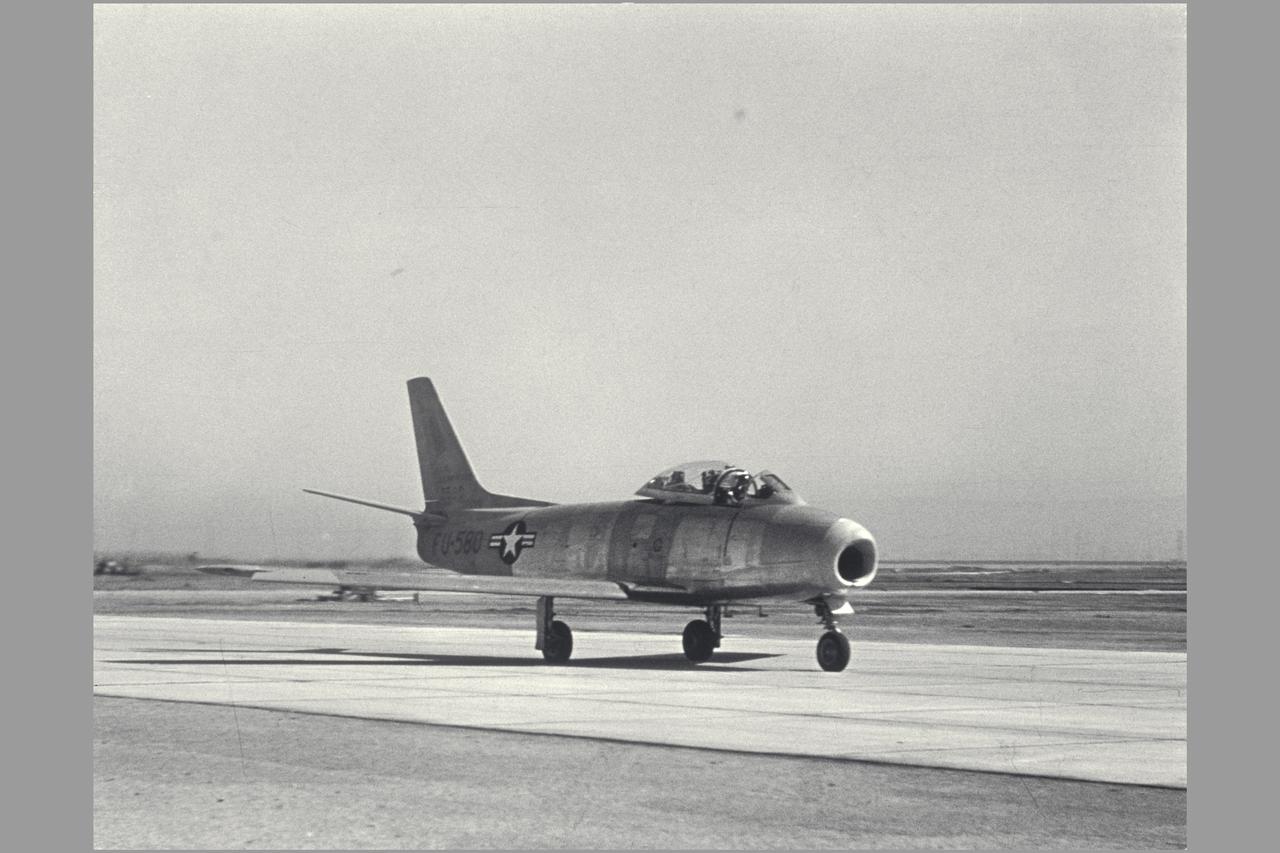
F-86E (AF 50-580). Gunsight Tracking and Guidance and Control Displays. Note: Used in publication in Flight Research at Ames; 57 Years of Development and Validation of Aeronautical Technology NASA SP-1998-3300 fig 78
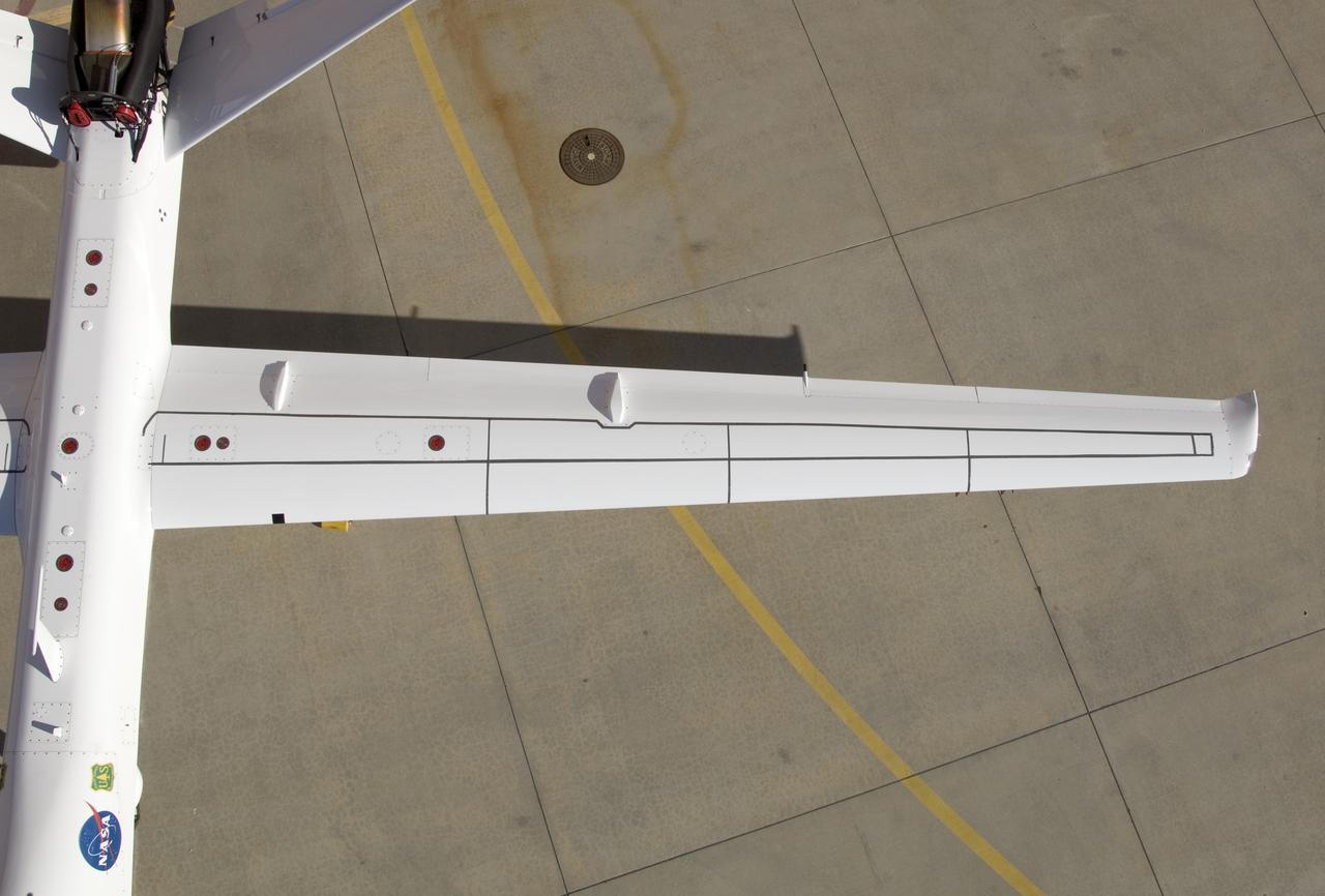
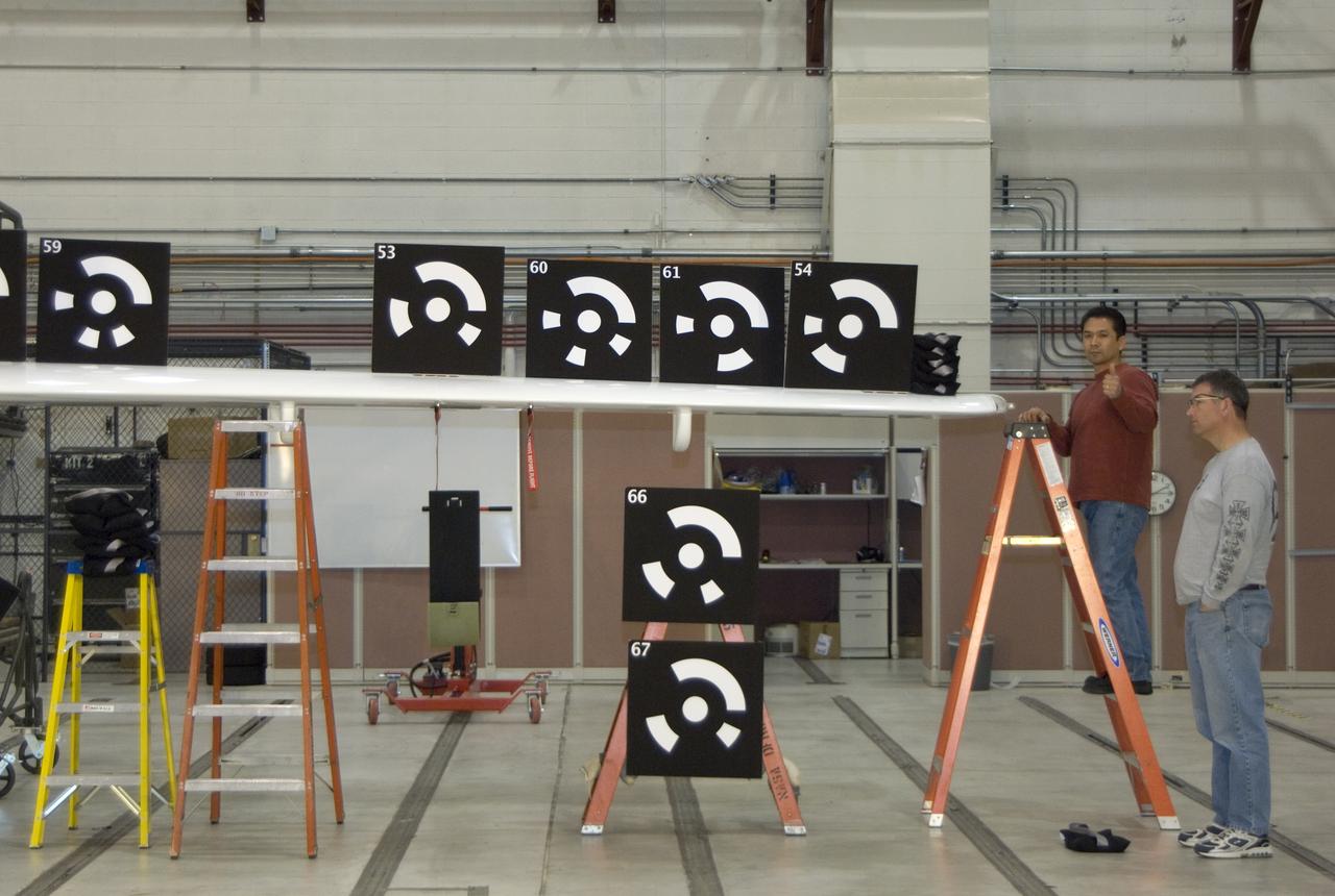
Although the new fiber optic sensors on the Ikhana, which are located on fibers that are the diameter of a human hair, are not visible, the sealant used to cover them can be seen in this view from above the left wing. NASA Dryden Flight Research Center is evaluating an advanced fiber optic-based sensing technology installed on the wings of NASA's Ikhana aircraft. The fiber optic system measures and displays the shape of the aircraft's wings in flight. There are other potential safety applications for the technology, such as vehicle structural health monitoring. If an aircraft structure can be monitored with sensors and a computer can manipulate flight control surfaces to compensate for stresses on the wings, structural control can be established to prevent situations that might otherwise result in a loss of control.
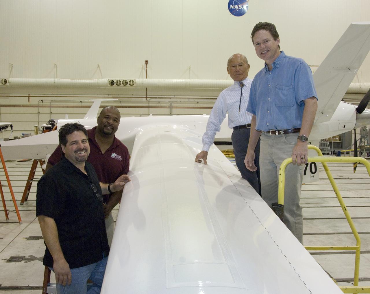
Ikhana fiber optic wing shape sensor team: clockwise from left, Anthony "Nino" Piazza, Allen Parker, William Ko and Lance Richards. The sensors, located along a fiber the thickness of a human hair, aren't visible in the center of the Ikhana aircraft's left wing. NASA Dryden Flight Research Center is evaluating an advanced fiber optic-based sensing technology installed on the wings of NASA's Ikhana aircraft. The fiber optic system measures and displays the shape of the aircraft's wings in flight. There are other potential safety applications for the technology, such as vehicle structural health monitoring. If an aircraft structure can be monitored with sensors and a computer can manipulate flight control surfaces to compensate for stresses on the wings, structural control can be established to prevent situations that might otherwise result in a loss of control.
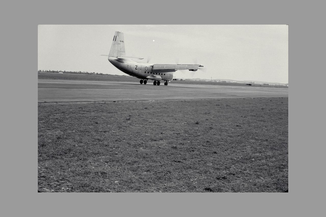
3/4 REAR VIEW OF Breguet 941 AIRPLANE; FLIGHT EVALUATION, MAY 1963. Boundary Layer Control, STOL, and V/STOL Research. Fig. 105 NASA SP Flight Research at Ames: 57 Years of Development and Validation of Aeronautical Technology
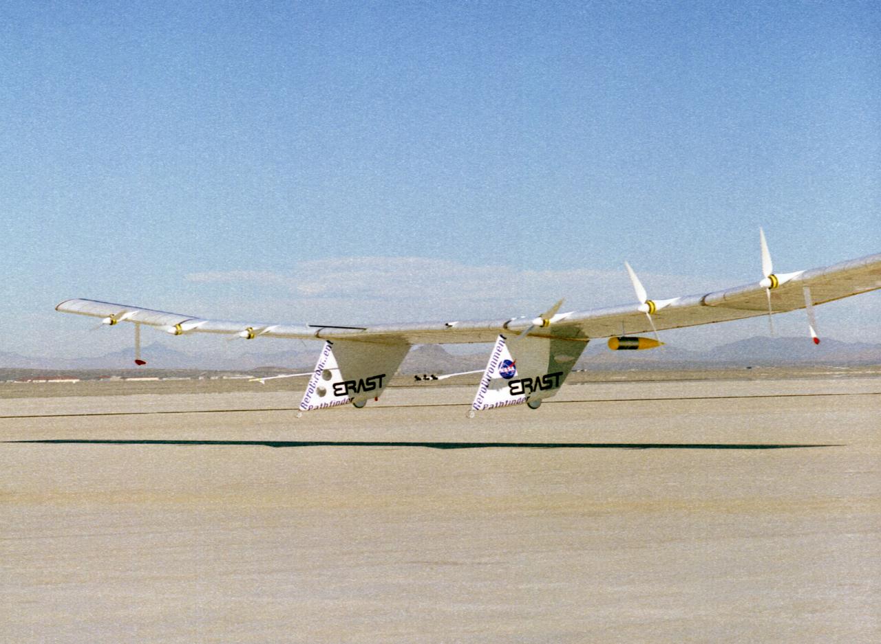
The Pathfinder solar-powered research aircraft settles in for landing on the bed of Rogers Dry Lake at the Dryden Flight Research Center, Edwards, California, after a successful test flight Nov. 19, 1996. The ultra-light craft flew a racetrack pattern at low altitudes over the flight test area for two hours while project engineers checked out various systems and sensors on the uninhabited aircraft. The Pathfinder was controlled by two pilots, one in a mobile control unit which followed the craft, the other in a stationary control station. Pathfinder, developed by AeroVironment, Inc., is one of several designs being evaluated under NASA's Environmental Research Aircraft and Sensor Technology (ERAST) program.
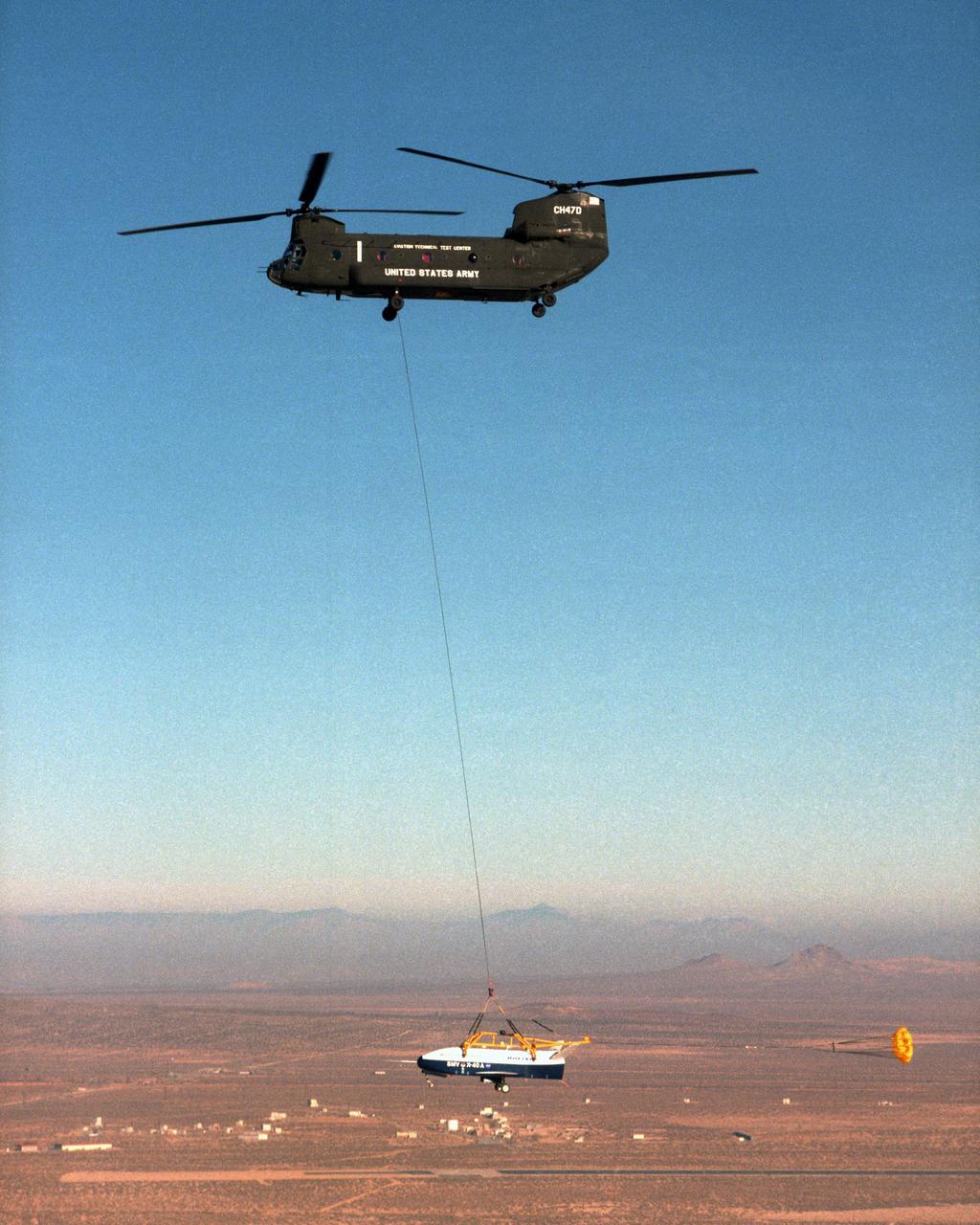
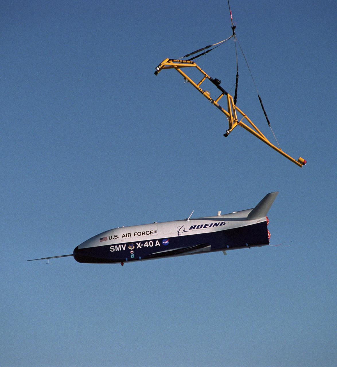
With a small stabilization parachute trailing behind, the X-40 sub-scale technology demonstrator is suspended under a U.S. Army CH-47 Chinook cargo helicopter during a captive-carry test flight at NASA's Dryden Flight Research Center, Edwards, California. The captive carry flights are designed to verify the X-40's navigation and control systems, rigging angles for its sling, and stability and control of the helicopter while carrying the X-40 on a tether. Following a series of captive-carry flights, the X-40 made free flights from a launch altitude of about 15,000 feet above ground, gliding to a fully autonomous landing. The X-40 is an unpowered 82 percent scale version of the X-37, a Boeing-developed spaceplane designed to demonstrate various advanced technologies for development of future lower-cost access to space vehicles.
The X-40 sub-scale technology demonstrator is suspended under a U.S. Army CH-47 Chinook cargo helicopter during a captive-carry test flight at NASA's Dryden Flight Research Center, Edwards, California. The captive carry flights are designed to verify the X-40's navigation and control systems, rigging angles for its sling, and stability and control of the helicopter while carrying the X-40 on a tether. Following a series of captive-carry flights, the X-40 made free flights from a launch altitude of about 15,000 feet above ground, gliding to a fully autonomous landing. The X-40 is an unpowered 82 percent scale version of the X-37, a Boeing-developed spaceplane designed to demonstrate various advanced technologies for development of future lower-cost access to space vehicles.
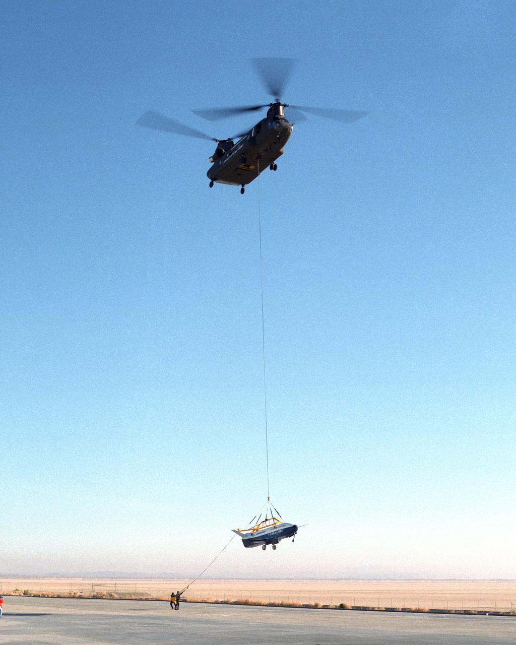
Ground crewmen help guide the alignment of the X-40 technology demonstrator as the experimental craft is gently lowered to the ground by a U.S. Army CH-47 Chinook cargo helicopter following a captive-carry test flight at NASA's Dryden Flight Research Center, Edwards, California. The X-40 is an unpowered 82 percent scale version of the X-37, a Boeing-developed spaceplane designed to demonstrate various advanced technologies for development of future lower-cost access to space vehicles. The X-37 will be carried into space aboard a space shuttle and then released to perform various maneuvers and a controlled re-entry through the Earth's atmosphere to an airplane-style landing on a runway, controlled entirely by pre-programmed computer software. Following a series of captive-carry flights, the X-40 made several free flights from a launch altitude of about 15,000 feet above ground, gliding to a fully autonomous landing. The captive carry flights helped verify the X-40's navigation and control systems, rigging angles for its sling, and stability and control of the helicopter while carrying the X-40 on a tether.

iss067e188778 (July 16, 2022) --- NASA astronaut and Expedition 67 Flight Engineer Bob Hines activates a CubeLab Satellite to validate a new attitude control technology for small satellites. The experimental device, designed by the University of Kentucky in partnership with TangoLab, was launched to the International Space Station aboard Northrop Grumman's Cygnus space freighter.
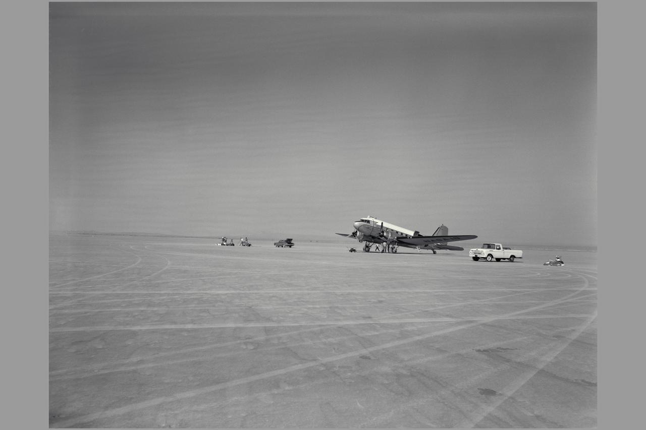
R4D-6 (Bu. No. 99827 NACA 18, NASA 701). TAKE-OFF MONITOR TEST, EDWARDS AIR FORCE BASE. Gunsight Tracking and Guidance and Control Displays. Note: Used in publication in Flight Research at Ames; 57 Years of Development and Validation of Aeronautical Technology NASA SP-1998-3300 fig 76

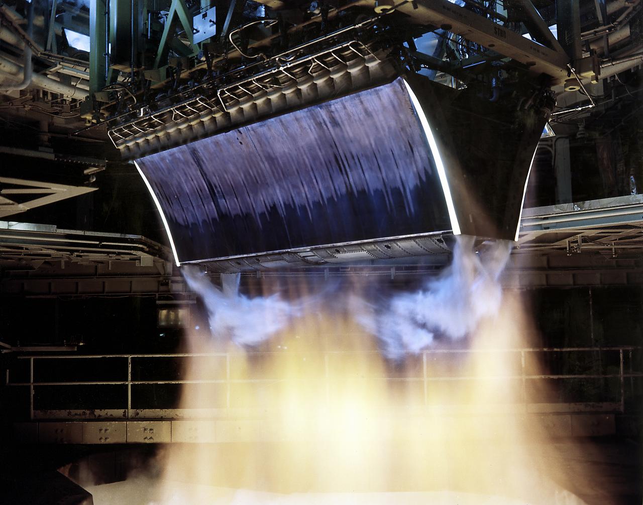
The X-37 advanced technology demonstrator flaperon unit was one of the first ever thermal and mechanical qualification tests of a carbon-carbon control surface designed for space flight. The test also featured extensive use of high-temperature fiber optic strain sensors. Peak temperatures reached 2,500 degrees Fahrenheit.
6 degree V/STOL Control Systems Research All Axes, Simulator (simulator pilot: Richard K Greif) at the Ames Research Center, Moffett Field, CA Note: Used in publication in Flight Research at Ames; 57 Years of Development and Validation of Aeronautical Technology NASA SP-1998-3300 fig. 113
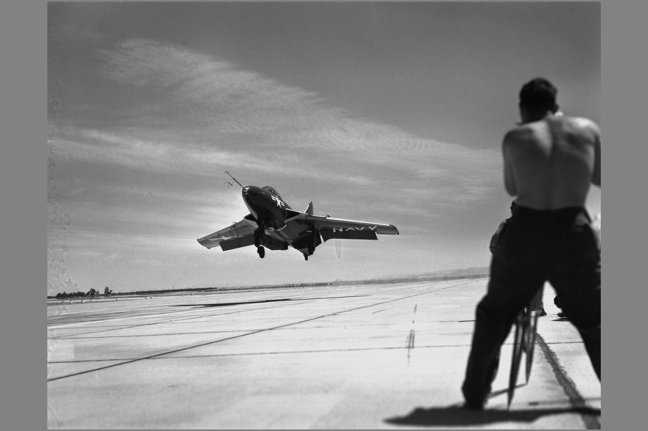
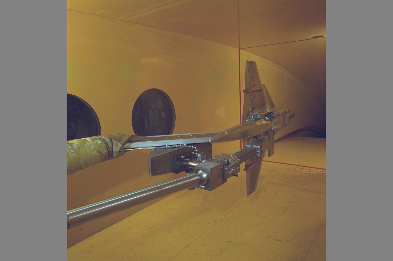
Grumman F9F-6 (Bu. No. 128138) Cougar airplane. EVALUATION OF CARRIER APPROACH TECHNIQUES Boundary Layer Control, STOL, and V/STOL Note: Used in publication in Flight Research at Ames; 57 Years of Development and Validation of Aeronautical Technology NASA SP-1998-3300 fig. 101
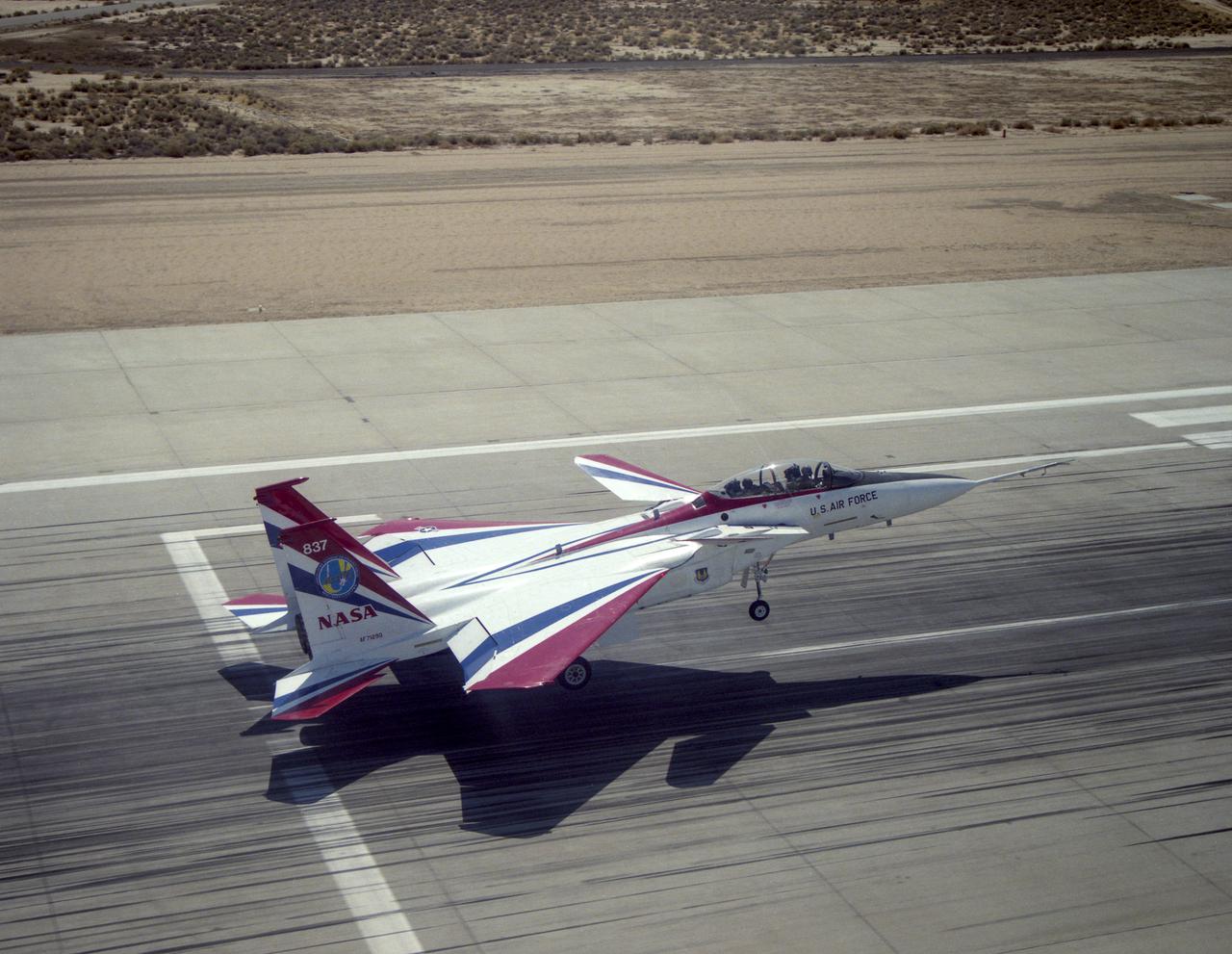
The F-15 Advanced Controls Technology for Integrated Vehicles, the first pre-production F-15B, shows its canards. Less obvious are the multi-axis thrust vectoring exhaust nozzles.

S73-37251 (23 November 1973) --- Astronaut Bruce McCandless II, left, shows off a mock-up of the occulting disc for the T025 Coronagraph Contamination Measurement Engineering and Technology Experiment to be used by the crewmen of the third manned Skylab mission (Skylab 4), now into their eighth day in Earth orbit. On the right is flight director Neil B. Hutchinson. The men are in the Mission Operations Control Room (MOCR) of the Mission Control Center (MCC) at Johnson Space Center. Photo credit: NASA
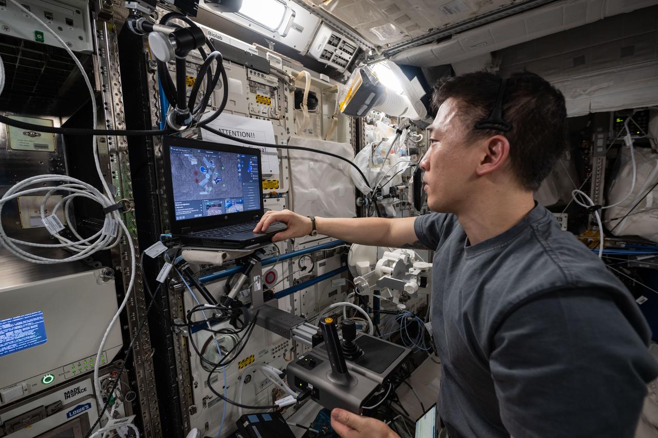
iss073e0416906 (July 21, 2025) --- NASA astronaut and Expedition 73 Flight Engineer Jonny Kim tests space-to-ground robotic controlling methods on a laptop computer inside the International Space Station's Columbus laboratory module. The Surface Avatar experiment explores ways to control robotic vehicles on a planetary surface from an orbiting spacecraft using a variety of technologies including consoles, touchscreens, haptics, and virtual reality goggles that may benefit future space exploration.
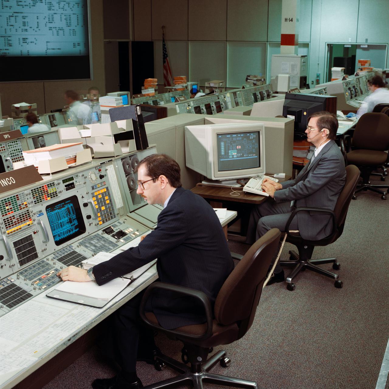
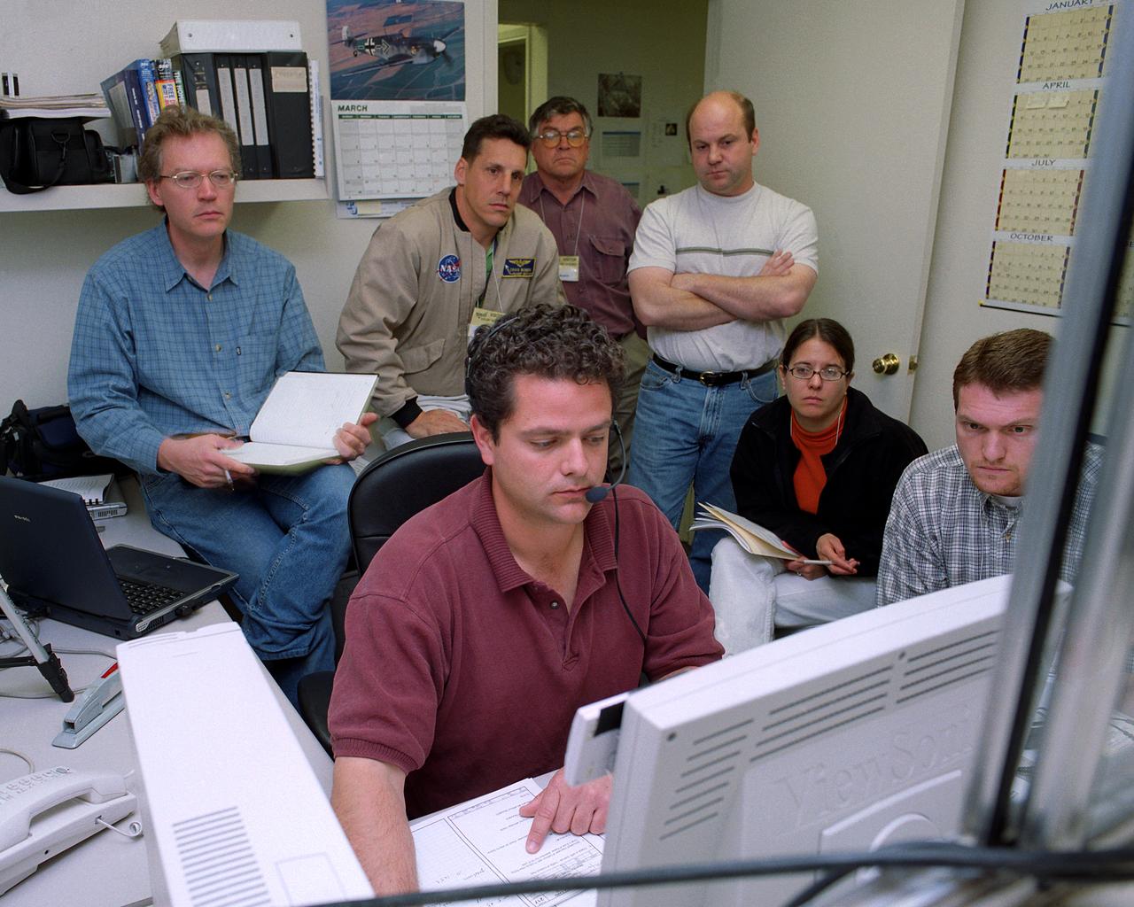
Instrumentation and Communications Officer (INCO) John F. Muratore monitors conventional workstation displays during an STS-26 simulation in JSC Mission Control Center (MCC) Bldg 30 Flight Control Room (FCR). Next to Muratore an operator views the real time data system (RTDS), an expert system. During the STS-29 mission two conventional monochrome console display units will be removed and replaced with RTDS displays. View is for the STS-29 press kit from Office of Aeronautics and Space Technology (OAST) RTDS.
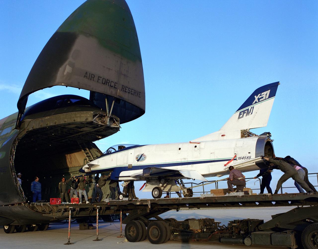
The X-31 Enhanced Fighter Maneuverability Technology Demonstrator Aircraft, based at the NASA Dryden Flight Research Center, Edwards, California, begins rolling aboard an Air Force Reserve C-5 transport which ferried it on May 22, 1995 to Europe where it was flown in the Paris Air Show in June 1995. To fit in the C-5 the right wing of the X-31 had to be removed. At the air show, the X-31 demonstrated the value of using thrust vectoring (directing engine exhaust flow) coupled with advanced flight control systems to provide controlled flight at very high angles of attack.

A NASA F/A-18, specially modified to test the newest and most advanced system technologies, on its first research flight on May 21, 1993, at NASA's Dryden Flight Research Facility, Edwards, California. Flown by Dryden in a multi-year, joint NASA/DOD/industry program, the F/A-18 former Navy fighter was modified into a unique Systems Research Aircraft (SRA) to investigate a host of new technologies in the areas of flight controls, airdata sensing and advanced computing. The primary goal of the SRA program was to validate through flight research cutting-edge technologies which could benefit future aircraft and spacecraft by improving efficiency and performance, reducing weight and complexity, with a resultant reduction on development and operational costs.

The ribbon is cut and the new Checkout and Launch Control System (CLCS) declared operational. Those taking part in the ceremony are (from left) Joseph Rothenberg, NASA Associate Administrator for Space Flight; Pam Gillespie, from Rep. Dave Weldon's office; Roy Bridges, Kennedy Space Center director; Dave King, director of Shuttle Processing; Retha Hart, deputy associate director, Spaceport Technology Management Office; and Ron Dittemore, manager, Space Shuttle Program. The new control room will be used to process the Orbital Maneuvering System pods and Forward Reaction Control System modules at the HMF. This hardware is removed from Space Shuttle orbiters and routinely taken to the HMF for checkout and servicing
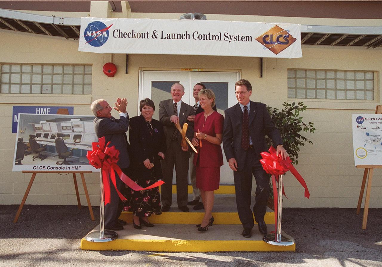
The ribbon is cut and the new Checkout and Launch Control System (CLCS) declared operational. Those taking part in the ceremony are (from left) Joseph Rothenberg, NASA Associate Administrator for Space Flight; Pam Gillespie, from Rep. Dave Weldon's office; Roy Bridges, Kennedy Space Center director; Dave King, director of Shuttle Processing; Retha Hart, deputy associate director, Spaceport Technology Management Office; and Ron Dittemore, manager, Space Shuttle Program. The new control room will be used to process the Orbital Maneuvering System pods and Forward Reaction Control System modules at the HMF. This hardware is removed from Space Shuttle orbiters and routinely taken to the HMF for checkout and servicing
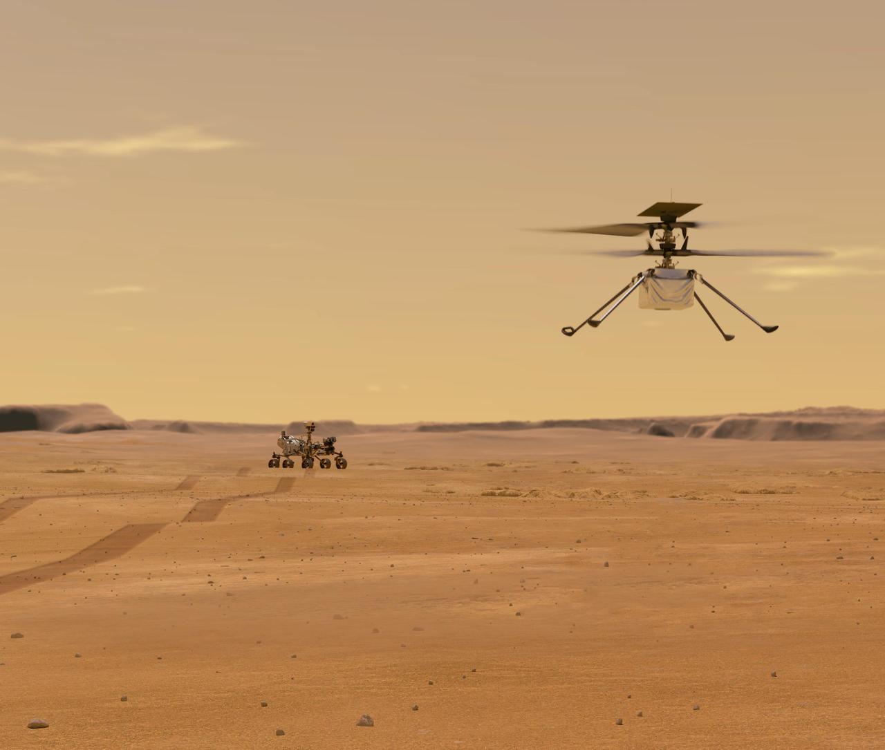
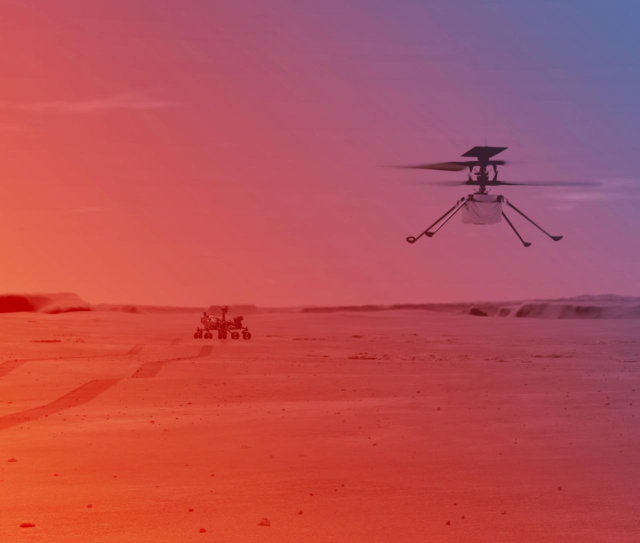
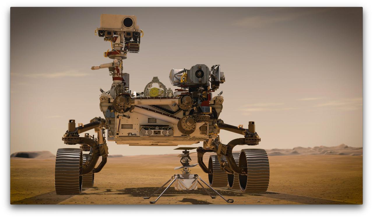
This illustration depicts Mars Helicopter Ingenuity during a test flight on Mars. Ingenuity was taken to the Red Planet strapped to the belly of the Perseverance rover (seen in the background). Ingenuity, a technology experiment, will be the first aircraft to attempt controlled flight on another planet. It will arrive on Mars on Feb. 18, 2021, attached to the belly of NASA's Mars 2020 Perseverance rover. Ingenuity is expected to attempt its first flight test in spring 2021. https://photojournal.jpl.nasa.gov/catalog/PIA24127

Engineers at NASA‘s Armstrong Flight Research Center sit in a control room to monitor the remotely-piloted Ikhana aircraft during a test flight. The test flight was used to validate key technologies and operations necessary to receive approval from the FAA’s to fly the aircraft in the National Airspace System June 12, 2018, without a safety chase aircraft.
Wing Deployment Sequence #3: The deployable, inflatable wing technology demonstrator experiment aircraft's wings fully deployed during flight following separation from its carrier aircraft during a flight conducted by the NASA Dryden Flight Research Center, Edwards, Californiaornia. The inflatable wing project represented a basic flight research effort by Dryden personnel. Three successful flights of the I2000 inflatable wing aircraft occurred. During the flights, the team air-launched the radio-controlled (R/C) I2000 from an R/C utility airplane at an altitude of 800-1000 feet. As the I2000 separated from the carrier aircraft, its inflatable wings "popped-out," deploying rapidly via an on-board nitrogen bottle. The aircraft remained stable as it transitioned from wingless to winged flight. The unpowered I2000 glided down to a smooth landing under complete control.
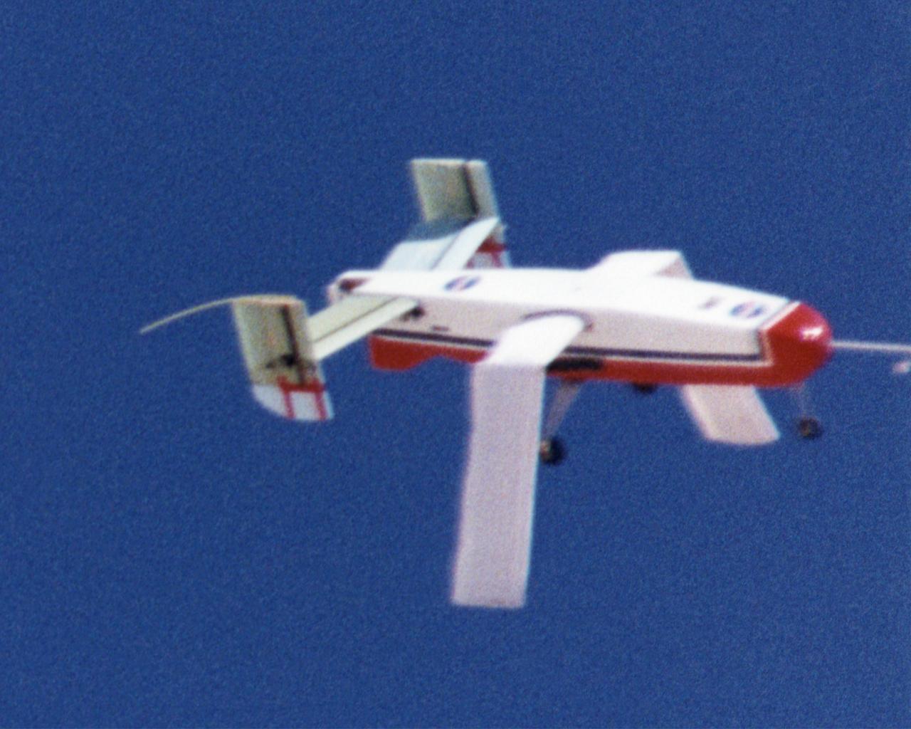
Wing Deployment Sequence #2: The deployable, inflatable wing technology demonstrator experiment aircraft's wings continue deploying following separation from its carrier aircraft during a flight conducted by the NASA Dryden Flight Research Center, Edwards, California. The inflatable wing project represented a basic flight research effort by Dryden personnel. Three successful flights of the I2000 inflatable wing aircraft occurred. During the flights, the team air-launched the radio-controlled (R/C) I2000 from an R/C utility airplane at an altitude of 800-1000 feet. As the I2000 separated from the carrier aircraft, its inflatable wings "popped-out," deploying rapidly via an on-board nitrogen bottle. The aircraft remained stable as it transitioned from wingless to winged flight. The unpowered I2000 glided down to a smooth landing under complete control.
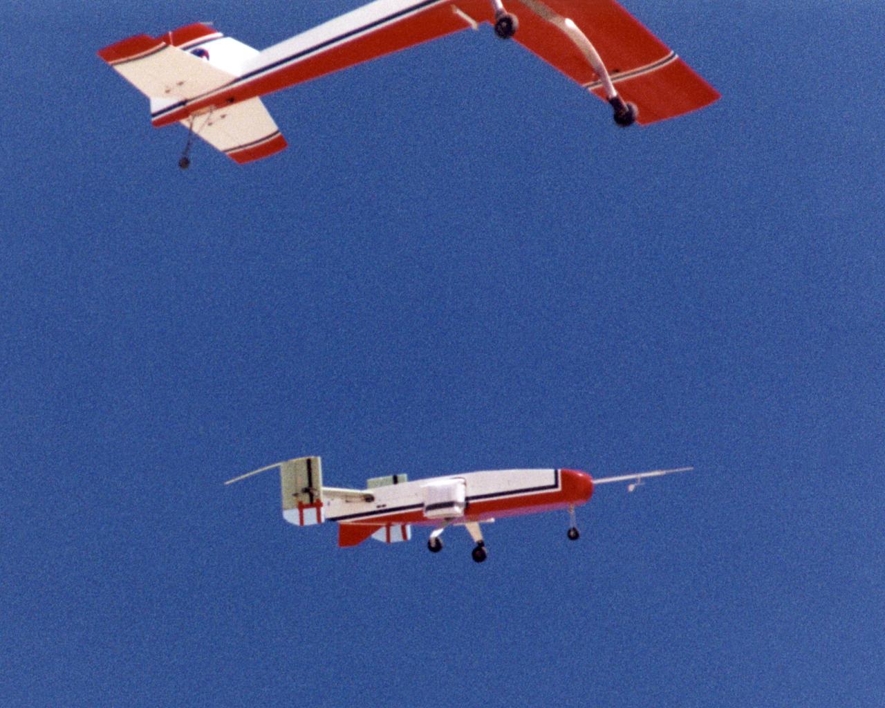
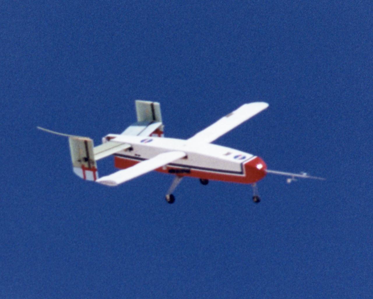
The deployable, inflatable wing technology demonstrator experiment separates from its carrier aircraft during a flight conducted by the NASA Dryden Flight Research Center, Edwards, California. The inflatable wing project represented a basic flight research effort by Dryden personnel. Three successful flights of the I2000 inflatable wing aircraft occurred. During the flights, the team air-launched the radio-controlled (R/C) I2000 from an R/C utility airplane at an altitude of 800-1000 feet. As the I2000 separated from the carrier aircraft, its inflatable wings "popped-out," deploying rapidly via an on-board nitrogen bottle. The aircraft remained stable as it transitioned from wingless to winged flight. The unpowered I2000 glided down to a smooth landing under complete control.
The deployable, inflatable wing technology demonstrator experiment aircraft looks good during a flight conducted by the NASA Dryden Flight Research Center, Edwards, California. The inflatable wing project represented a basic flight research effort by Dryden personnel. Three successful flights of the I2000 inflatable wing aircraft occurred. During the flights, the team air-launched the radio-controlled (R/C) I2000 from an R/C utility airplane at an altitude of 800-1000 feet. As the I2000 separated from the carrier aircraft, its inflatable wings "popped-out," deploying rapidly via an on-board nitrogen bottle. The aircraft remained stable as it transitioned from wingless to winged flight. The unpowered I2000 glided down to a smooth landing under complete control.
The deployable, inflatable wing technology demonstrator experiment aircraft maintains a steady attitude following separation from its carrier aircraft during a flight conducted by the NASA Dryden Flight Research Center, Edwards, California. The inflatable wing project represented a basic flight research effort by Dryden personnel. Three successful flights of the I2000 inflatable wing aircraft occurred. During the flights, the team air-launched the radio-controlled (R/C) I2000 from an R/C utility airplane at an altitude of 800-1000 feet. As the I2000 separated from the carrier aircraft, its inflatable wings "popped-out," deploying rapidly via an on-board nitrogen bottle. The aircraft remained stable as it transitioned from wingless to winged flight. The unpowered I2000 glided down to a smooth landing under complete control.
Wing Deployment Sequence #1: The deployable, inflatable wing technology demonstrator experiment aircraft's wings begin deploying following separation from its carrier aircraft during a flight conducted by the NASA Dryden Flight Research Center, Edwards, California. The inflatable wing project represented a basic flight research effort by Dryden personnel. Three successful flights of the I2000 inflatable wing aircraft occurred. During the flights, the team air-launched the radio-controlled (R/C) I2000 from an R/C utility airplane at an altitude of 800-1000 feet. As the I2000 separated from the carrier aircraft, its inflatable wings "popped-out," deploying rapidly via an on-board nitrogen bottle. The aircraft remained stable as it transitioned from wingless to winged flight. The unpowered I2000 glided down to a smooth landing under complete control.
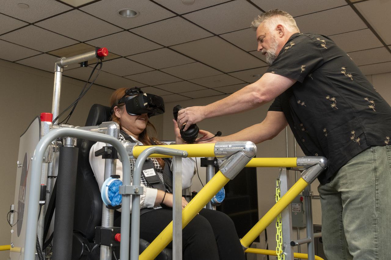
NASA employee Naomi Torres sits inside the air taxi passenger ride quality simulator at NASA’s Armstrong Flight Research Center in Edwards, California, as Curt Hanson, senior flight controls researcher for the Revolutionary Vertical Lift Technology project, sets up her equipment on Oct. 23, 2024. Studies continue in this lab to better understand passenger comfort for future air taxi rides.
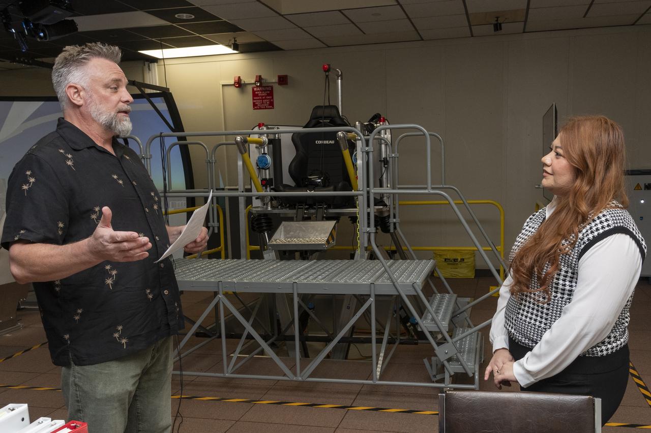
Curt Hanson, senior flight controls researcher for the Revolutionary Vertical Lift Technology project based at NASA’s Armstrong Flight Research Center in Edwards, California, explains the study about to begin to NASA employee and test subject Naomi Torres on Oct. 23, 2024. Behind them is the air taxi passenger ride quality simulator in NASA Armstrong’s Ride Quality Laboratory. Studies continue to better understand passenger comfort for future air taxi rides.
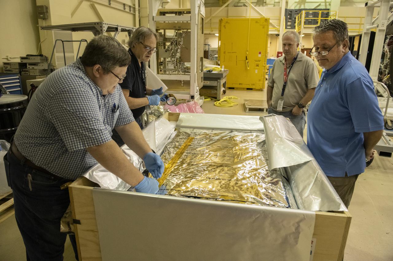
The 4-bed Carbon Dioxide Scrubber, new Environmental Control and Life Support Systems technology developed, built, tested, and integrated at NASA's Marshall Space Flight Center to be launched to the International Space Station, is readied for shipment to NASA's Wallops Flight Facility in Wallops Island, Virginia. The hardware will fly to space Aug. 1 via the Cygnus NG-16 commercial spacecraft, and will be tested aboard the space station for one year.
An illustration of NASA's Ingenuity Helicopter flying on Mars. Ingenuity, a technology demonstration experiment, will be the first aircraft to attempt powered, controlled flight on another planet. Ingenuity arrived at Mars on Feb. 18, 2021, attached to the belly of NASA's Mars 2020 Perseverance rover. Ingenuity is expected to attempt its first flight test in spring 2021. https://photojournal.jpl.nasa.gov/catalog/PIA24466

Dr. Forrest Carpenter, left, principal investigator for the third phase of CarpetDIEM, Carpet Determination in Entirety Measurements flights, monitors a test from one of the control rooms at NASA’s Armstrong Flight Research Center. Next to Carpenter is Brian Strovers, chief engineer for Commercial Supersonic Technology. The third phase of CarpetDIEM tested logistics and upgraded ground recording systems in preparation for the acoustic validation phase of the Quesst mission.
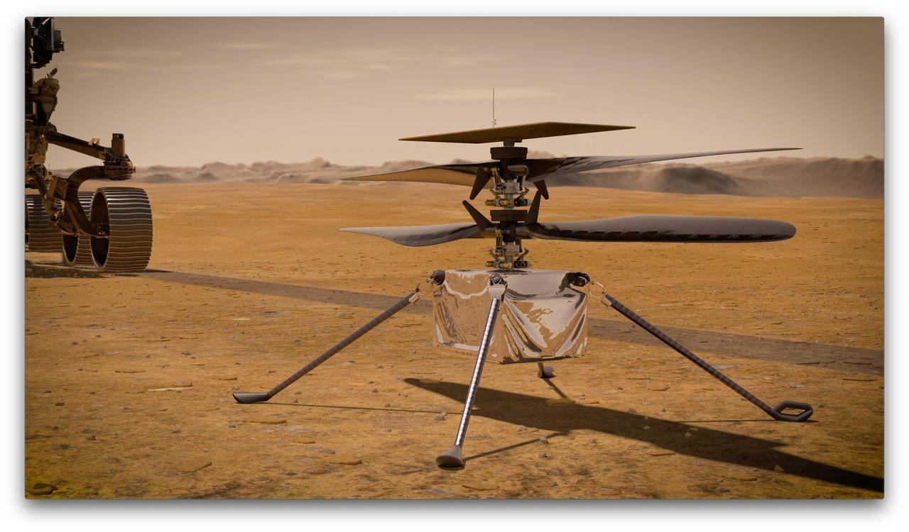
In this artist's concept, NASA's Ingenuity Mars Helicopter stands on the Red Planet's surface as NASA's Mars 2020 Perseverance rover (partially visible on the left) rolls away. Ingenuity, a technology experiment, will be the first aircraft to attempt controlled flight on another planet. It will arrive on Mars on Feb. 18, 2021, attached to the belly of NASA's Perseverance rover. Perseverance will deploy Ingenuity onto the surface of Mars, and Ingenuity is expected to attempt its first flight test in spring 2021. https://photojournal.jpl.nasa.gov/catalog/PIA23720
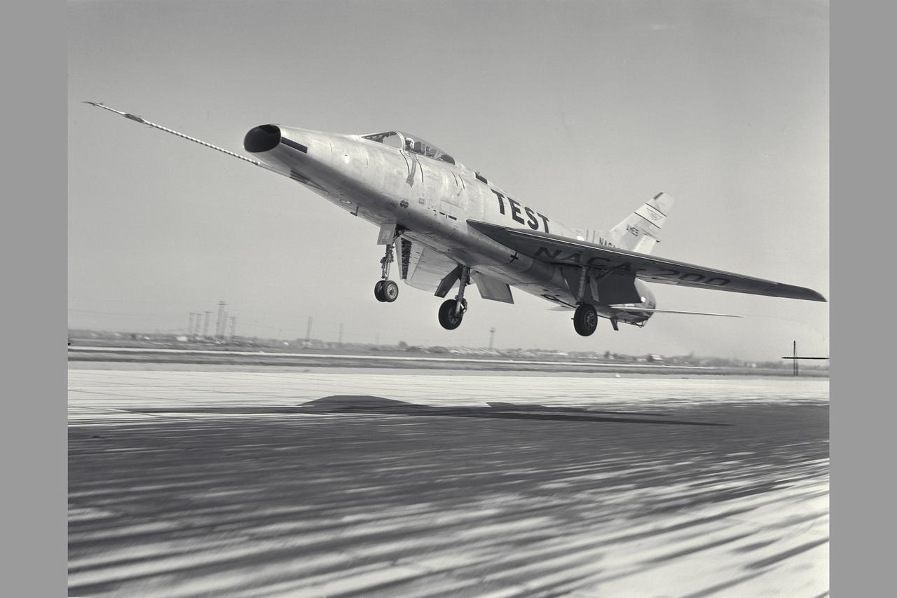
NACA Photographer North American F-100A (NACA-200) Super Sabre Airplane take-off. The blowing-tupe boundary-layer control on the leading- and trailing-edge provided large reductions in takeoff and landing approach speeds. Approach speeds were reduced by about 10 knots (Mar 1960). Note: Used in publication in Flight Research at Ames; 57 Years of Development and Validation of Aeronautical Technology NASA SP-1998-3300 fig. 102 and and Memoirs of a Flight Test Engneer NASA SP-2002-4525
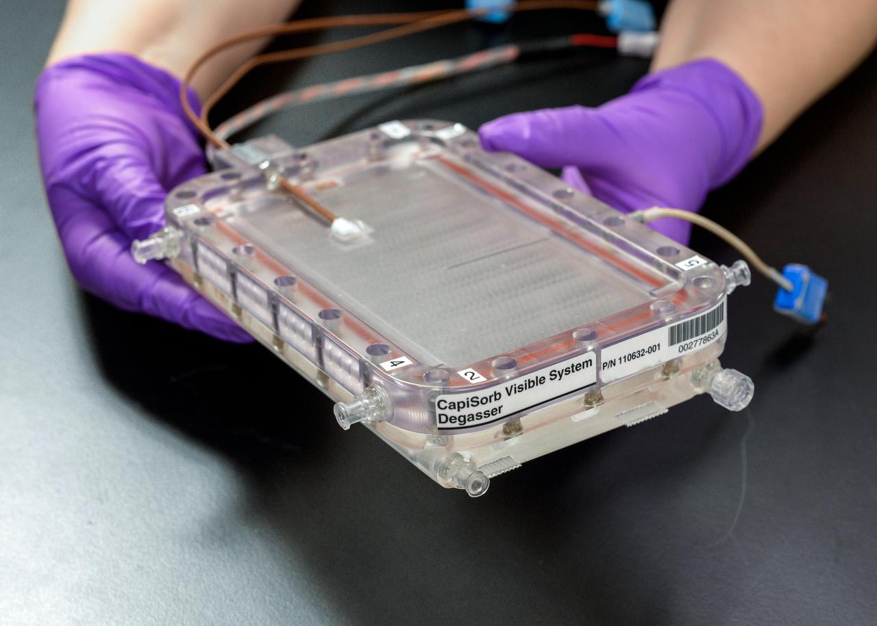
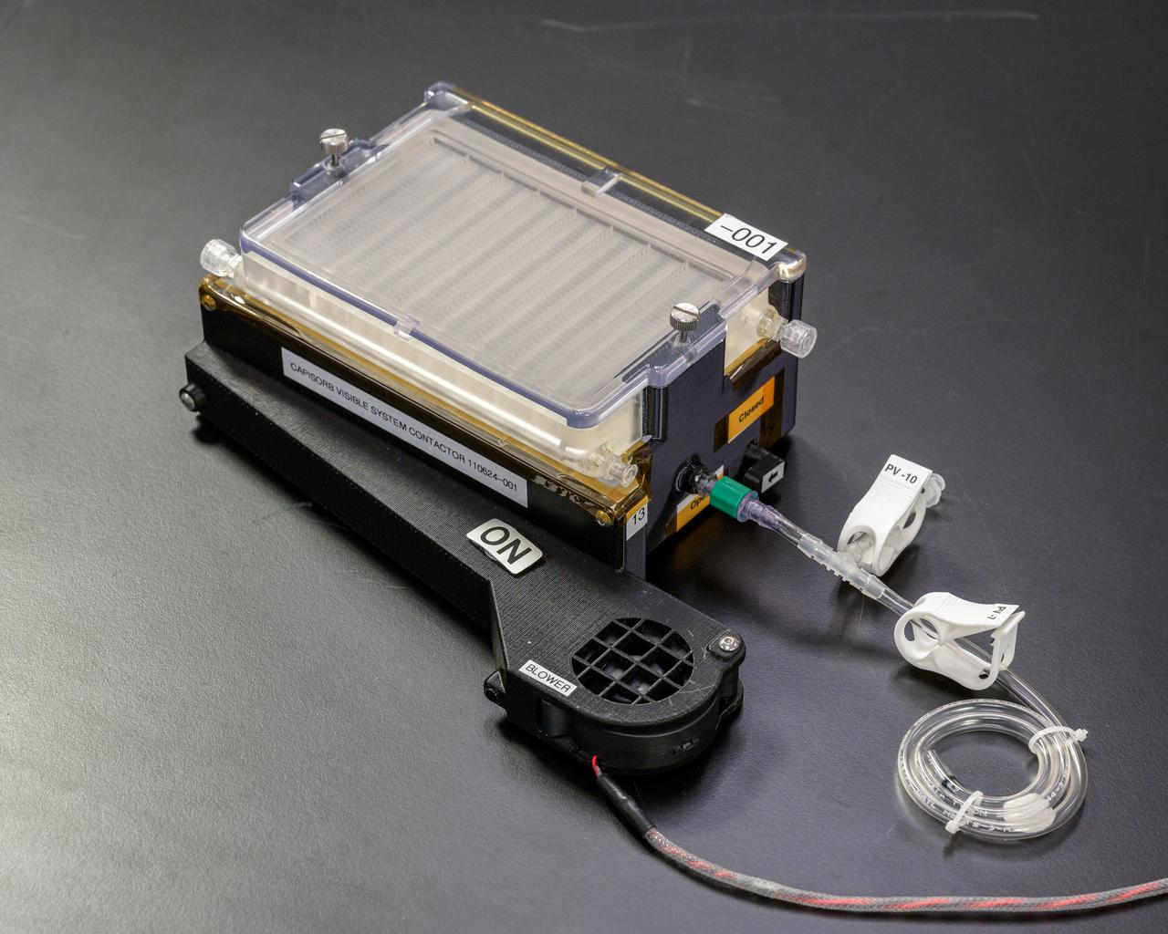
jsc2023e010167 (1/30/2023) --- CapiSorb Visible System flight unit degasser assembly in N240 room 133B. The CapiSorb Visible System will be launched on SpaceX CRS-27 in March 2023 to the International Space Station to demonstrate a liquid sorbent-based system that leverages the advantages of liquid control through capillary action to remove carbon dioxide from crewed atmospheres...Capillary wedges in the CapiSorb Visible System Degasser, shown here pre-flight, control and passively transport viscous liquid in microgravity in order to demonstrate capabilities needed for future liquid sorbent carbon dioxide removal technologies. The CapiSorb Visible System investigation demonstrates a liquid control using capillary forces, over a range of liquid properties that are characteristic of liquid carbon dioxide sorbents. Image courtesy of NASA's Ames Research Center.
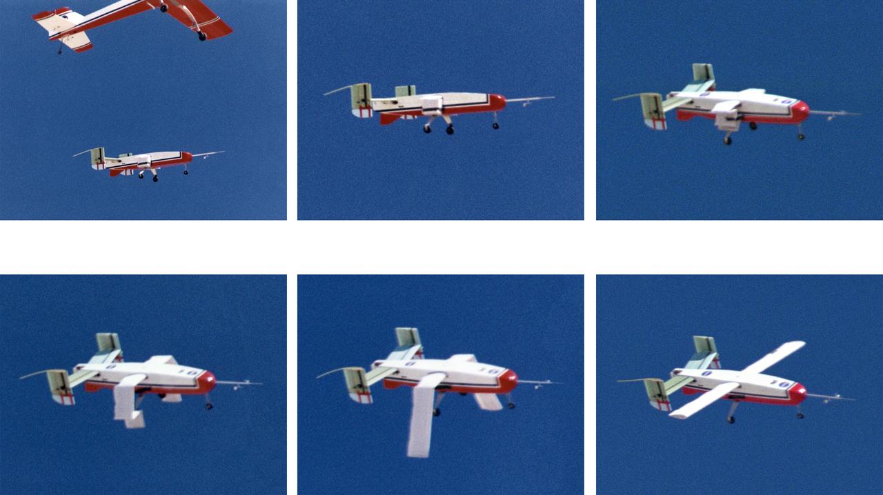
The deployable, inflatable wing technology demonstrator aircraft's wings begin deploying following separation from its carrier aircraft during a flight experiment conducted by the NASA Dryden Flight Research Center, Edwards, California. Wing deployment time is typically on the order of a third of a second, almost faster than the human eye can see. Three successful flights of the I2000 inflatable wing aircraft occurred. During the flights, the team air-launched the radio-controlled (R/C) I2000 from an R/C utility airplane at an altitude of 800-1000 feet. As the I2000 separated from the carrier aircraft, its inflatable wings "popped-out," deploying rapidly via an on-board nitrogen bottle. The aircraft remained stable as it transitioned from wingless to winged flight. The unpowered I2000 glided down to a smooth landing under complete control.
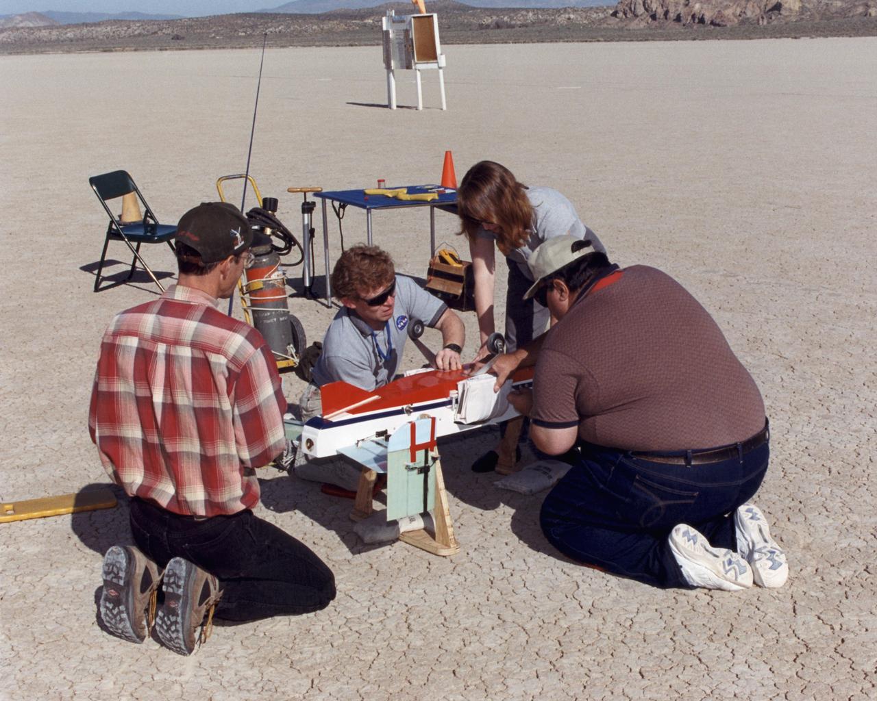
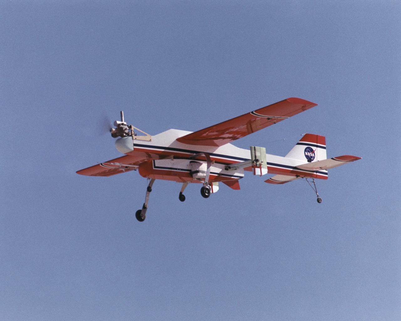
Inflatable Wing project personnel prepare a deployable, inflatable wing technology demonstrator experiment flown by the NASA Dryden Flight Research Center, Edwards, California. The inflatable wing project represented a basic flight research effort by Dryden personnel. Three successful flights of the I2000 inflatable wing aircraft occurred. During the flights, the team air-launched the radio-controlled (R/C) I2000 from an R/C utility airplane at an altitude of 800-1000 feet. As the I2000 separated from the carrier aircraft, its inflatable wings "popped-out," deploying rapidly via an on-board nitrogen bottle. The aircraft remained stable as it transitioned from wingless to winged flight. The unpowered I2000 glided down to a smooth landing under complete control.
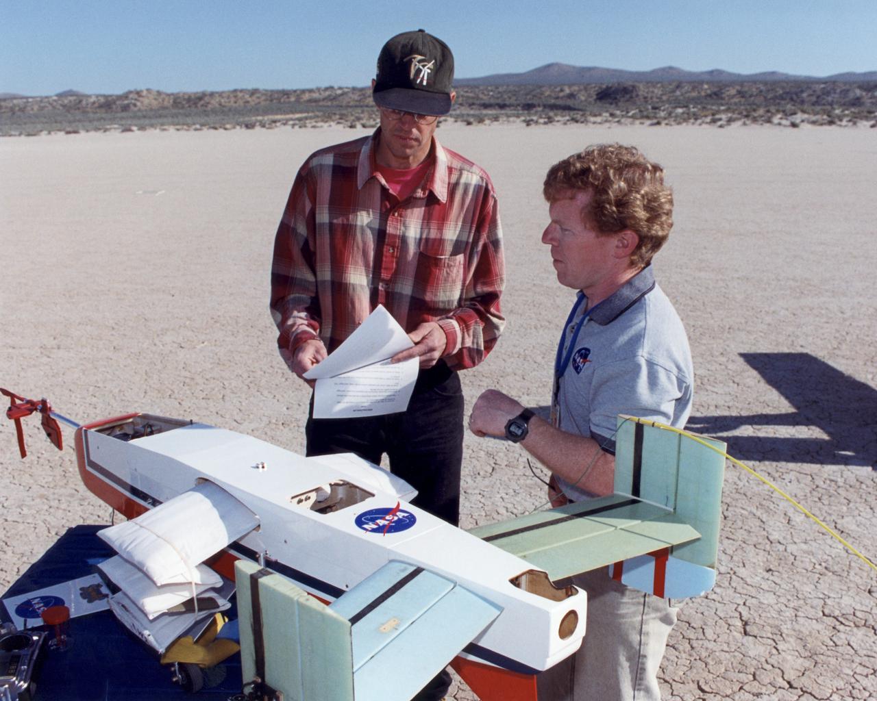
Engineers Jim Murray and Joe Pahle prepare a deployable, inflatable wing technology demonstrator experiment flown by the NASA Dryden Flight Research Center, Edwards, California. The inflatable wing project represented a basic flight research effort by Dryden personnel. Three successful flights of the I2000 inflatable wing aircraft occurred. During the flights, the team air-launched the radio-controlled (R/C) I2000 from an R/C utility airplane at an altitude of 800-1000 feet. As the I2000 separated from the carrier aircraft, its inflatable wings "popped-out," deploying rapidly via an on-board nitrogen bottle. The aircraft remained stable as it transitioned from wingless to winged flight. The unpowered I2000 glided down to a smooth landing under complete control.
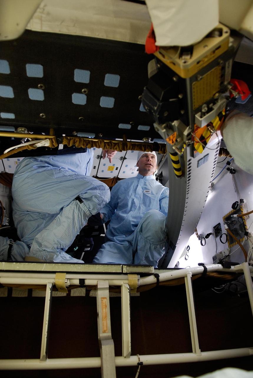
KENNEDY SPACE CENTER, FLA. -- On the flight deck of space shuttle Atlantis, STS-122 Mission Specialist Stanley Love looks at cables and controls. The STS-122 mission to the International Space Station is scheduled to launch at 2:45 p.m. Feb. 7 with a crew of seven. Atlantis will carry the Columbus Laboratory, Europe's largest contribution to the construction of the station. Columbus will support scientific and technological research in a microgravity environment. Columbus is a multifunctional, pressurized laboratory that will be permanently attached to the Harmony module to carry out experiments in materials science, fluid physics and biosciences, as well as to perform a number of technological applications. Photo credit: NASA/Kim Shiflett
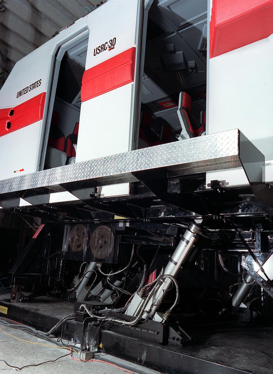
The development of the electric space actuator represents an unusual case of space technology transfer wherein the product was commercialized before it was used for the intended space purpose. MOOG, which supplies the thrust vector control hydraulic actuators for the Space Shuttle and brake actuators for the Space Orbiter, initiated development of electric actuators for aerospace and industrial use in the early 1980s. NASA used the technology to develop an electric replacement for the Space Shuttle main engine TVC actuator. An electric actuator is used to take passengers on a realistic flight to Jupiter at the US Space and Rocket Center, Huntsville, Alabama.
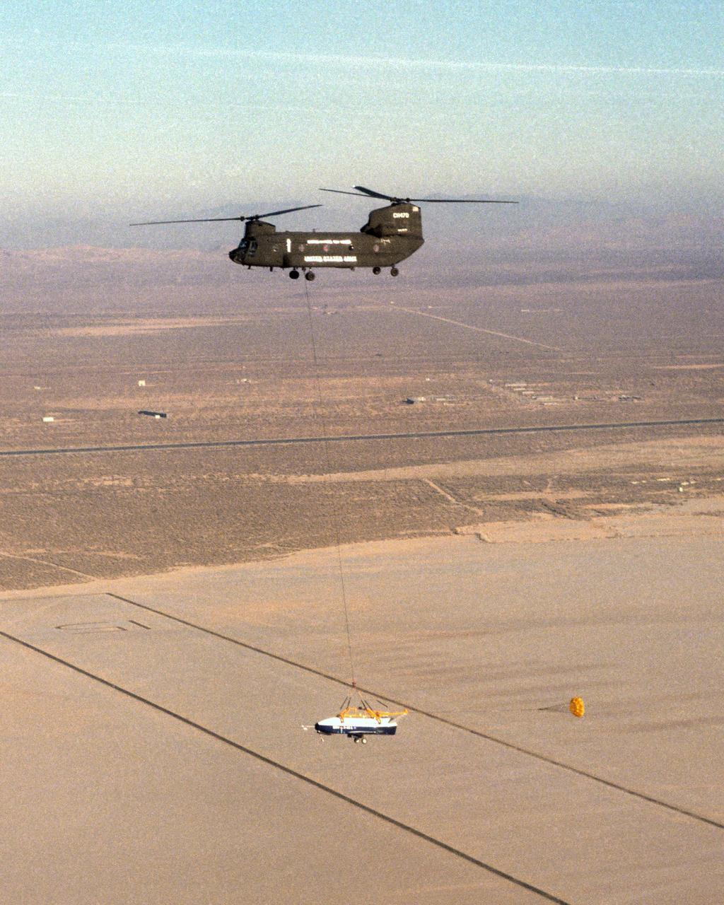
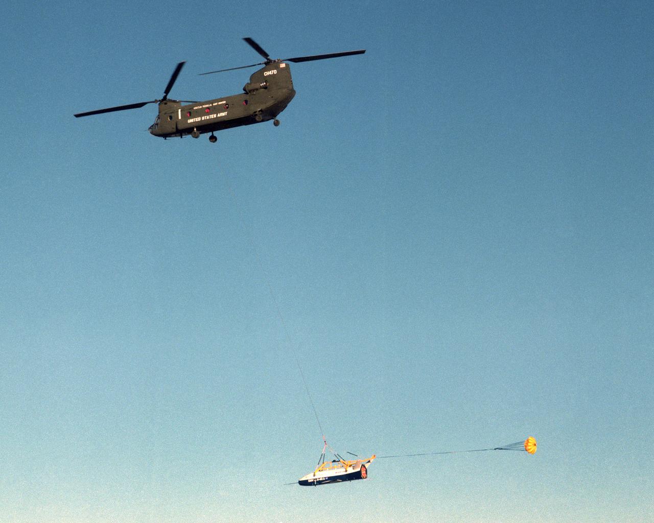
The X-40 sub-scale technology demonstrator and its U.S. Army CH-47 Chinook helicopter mothership fly over a dry lakebed runway during a captive-carry test flight from NASA's Dryden Flight Research Center, Edwards, California. The X-40 is attached to a sling which is suspended from the CH-47 by a 110-foot-long cable during the tests, while a small parachute trails behind to provide stability. The captive carry flights are designed to verify the X-40's navigation and control systems, rigging angles for its sling, and stability and control of the helicopter while carrying the X-40 on a tether. Following a series of captive-carry flights, the X-40 made free flights from a launch altitude of about 15,000 feet above ground, gliding to a fully autonomous landing. The X-40 is an unpowered 82 percent scale version of the X-37, a Boeing-developed spaceplane designed to demonstrate various advanced technologies for development of future lower-cost access to space vehicles.

NASA's F/A-18 Hornet is seen here in a banked turn over Rogers Dry Lake in the Mojave desert on an early research flight. It was flown by NASA's Dryden Flight Research Center, Edwards, California, in a multi-year, joint NASA/DOD/industry program, the former Navy fighter was modified into a unique Systems Research Aircraft (SRA) to investigate a host of new technologies in the areas of flight controls, airdata sensing and advanced computing. One of the more than 20 experiments tested aboard the SRA F-18 was an advanced air data sensing system which used a group of pressure taps flush-mounted on the forward fuselage to measure both altitude and wind speed and direction--critical data for flight control and research investigations. The Real-Time Flush Air Data Sensing system concept was evaluated for possible use on the X-33 and X-34 resuable space-launch vehicles. The primary goal of the SRA program was to validate through flight research cutting-edge technologies which could benefit future aircraft and spacecraft by improving efficiency and performance, reducing weight and complexity, with a resultant reduction on development and operational costs.
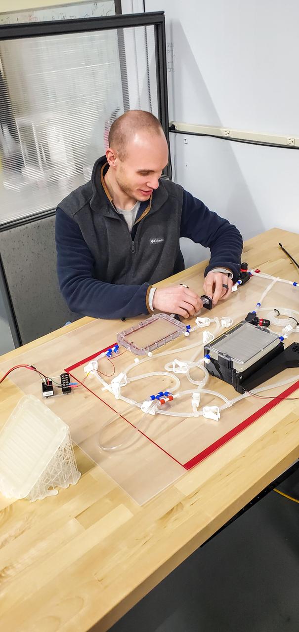
jsc2023e010172 (2/1/2023) --- Logan Torres, Design Engineer for the CapiSorb Visible System, configures the system pre-flight for performance testing. The capillary wedges in the degasser, contactor and capillary condensing heat exchanger control and passively transport viscous liquid in microgravity in order to demonstrate capabilities needed for future liquid sorbent carbon dioxide removal technologies. The CapiSorb Visible System investigation demonstrates a liquid control using capillary forces, over a range of properties that are characteristic of liquids which absorb carbon dioxide. Image courtesy of IRPI, LLC.
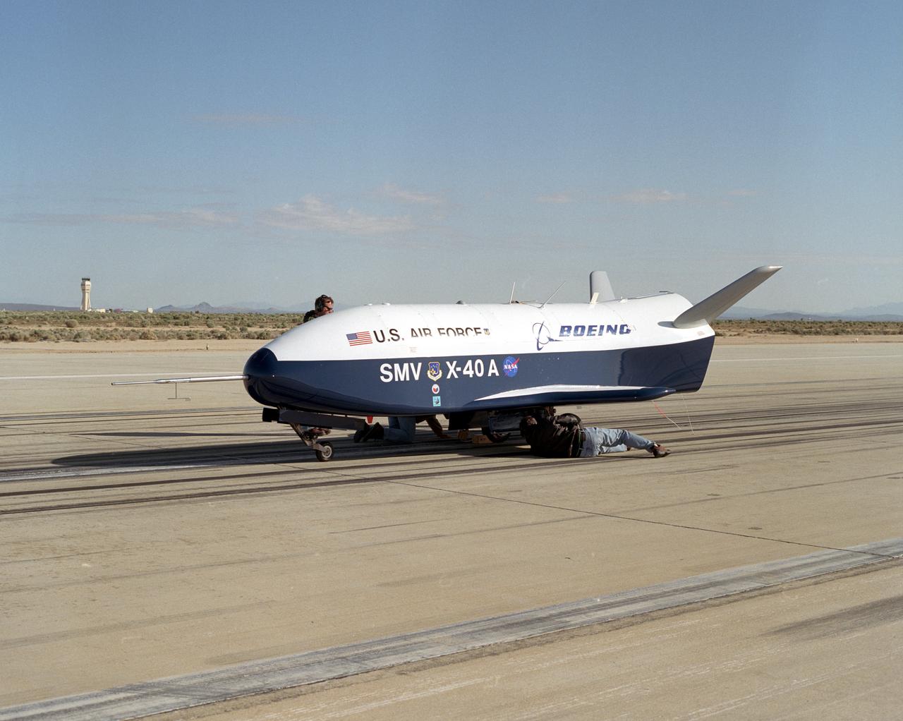
Second free-flight of the X-40A at the NASA Dryden Flight Research Center, on Edwards AFB, Calif., was made on Apr. 12, 2001. The unpowered X-40A, an 85 percent scale risk reduction version of the proposed X-37, is proving the capability of an autonomous flight control and landing system in a series of glide flights at Edwards. The April 12 flight introduced complex vehicle maneuvers during the landing sequence. The X-40A was released from an Army Chinook helicopter flying 15,050 feet overhead. Ultimately, the unpiloted X-37 is intended as an orbital testbed and technology demonstrator, capable of landing like an airplane and being quickly serviced for a follow-up mission.
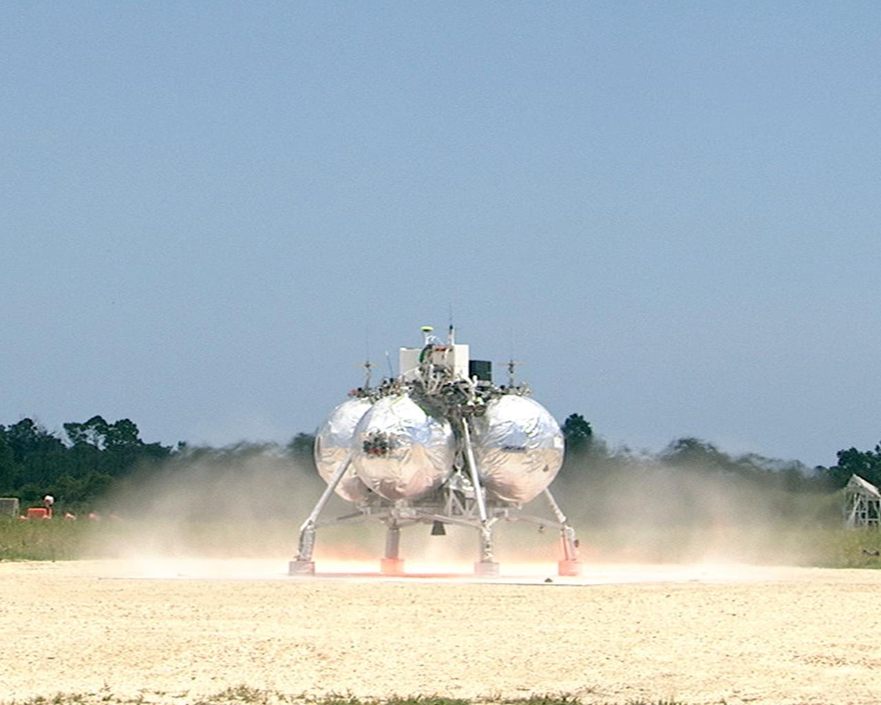
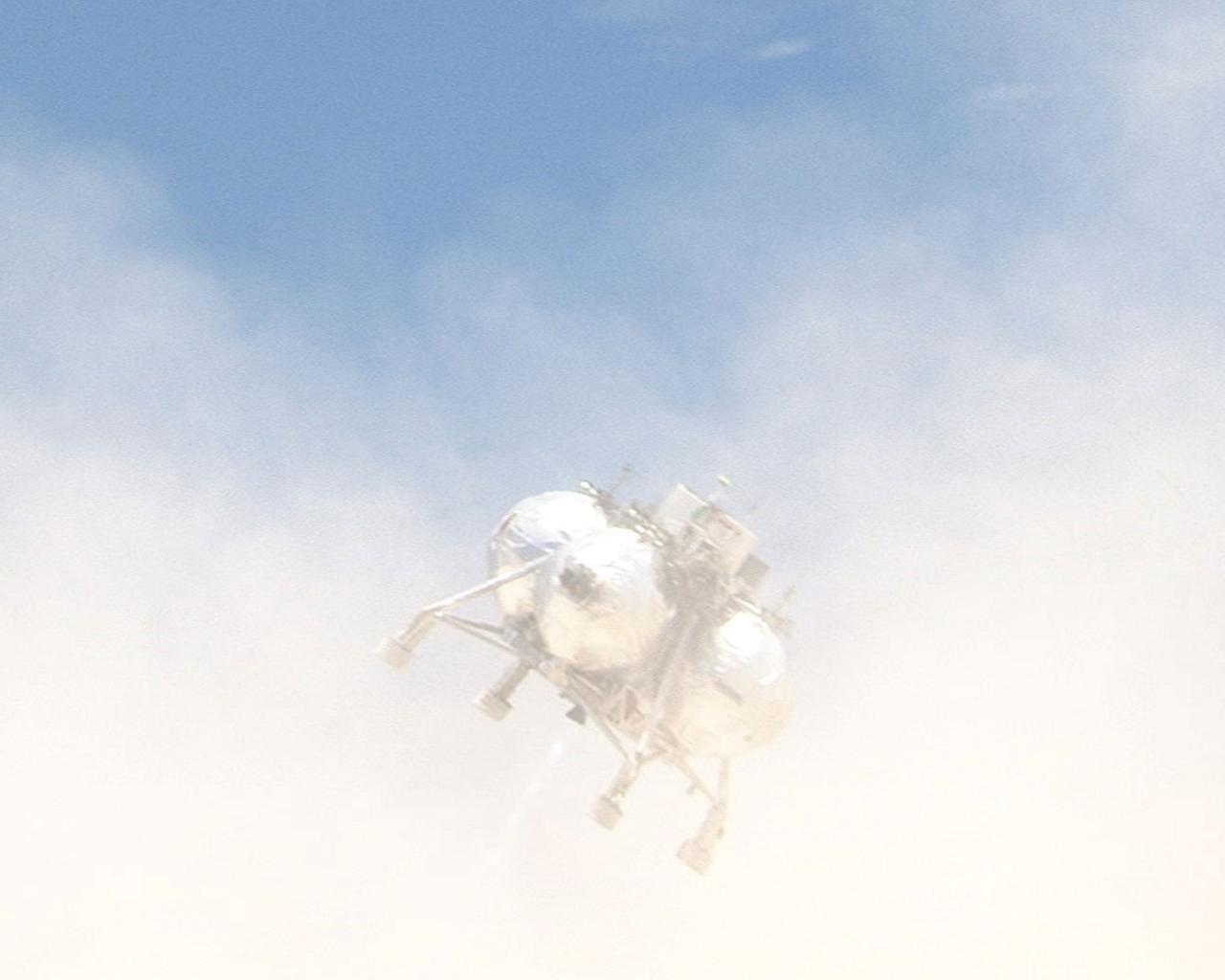
CAPE CANAVERAL, Fla. – At the Shuttle Landing Facility at NASA’s Kennedy Space Center in Florida, the Morpheus prototype lander begins to lift off of the ground during a free-flight test. Testing of the prototype lander had been ongoing at NASA’s Johnson Space Center in Houston in preparation for its first free-flight test at Kennedy Space Center. Morpheus was manufactured and assembled at JSC and Armadillo Aerospace. Morpheus is large enough to carry 1,100 pounds of cargo to the moon – for example, a humanoid robot, a small rover, or a small laboratory to convert moon dust into oxygen. The primary focus of the test is to demonstrate an integrated propulsion and guidance, navigation and control system that can fly a lunar descent profile to exercise the Autonomous Landing and Hazard Avoidance Technology, or ALHAT, safe landing sensors and closed-loop flight control. For more information on Project Morpheus, visit http://morpheuslander.jsc.nasa.gov/. Photo credit: NASA
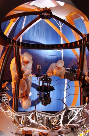
Engineers at Ball Aerospace test the Wavefront Sensing and Control testbed to ensure that the 18 primary mirror segments and one secondary mirror on JWST work as one. The test is performed on a 1/6 scale model of the JWST mirrors. Credit: NASA/Northrop Grumman/Ball Aerospace To read more about the James Webb Space Telescope go to: <a href="http://www.nasa.gov/topics/technology/features/partnerships.html" rel="nofollow">www.nasa.gov/topics/technology/features/partnerships.html</a> <b><a href="http://www.nasa.gov/centers/goddard/home/index.html" rel="nofollow">NASA Goddard Space Flight Center</a></b> is home to the nation's largest organization of combined scientists, engineers and technologists that build spacecraft, instruments and new technology to study the Earth, the sun, our solar system, and the universe.
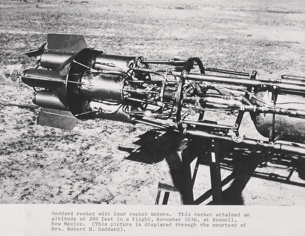
Goddard rocket with four rocket motors. This rocket attained an altitude of 200 feet in a flight, November 1936, at Roswell, New Mexico. From 1930 to 1941, Dr. Goddard made substantial progress in the development of progressively larger rockets which attained altitudes of 2400 meters, and refined his equipment for guidance and control, his techniques of welding, and his insulation, pumps, and other associated equipment. In many respects, Dr. Goddard laid the essential foundations of practical rocket technology
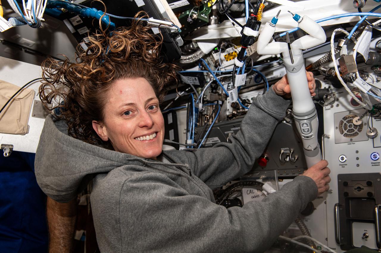
iss070e097708 (Feb. 21, 2024) -- NASA astronaut and Expedition 70 Flight Engineer Loral O’Hara shows off the miniaturized in vivo robotic assistant (MIRA), which is Virtual Incision’s miniaturized robotic assisted surgery system, which was used to conduct a robotic surgery technology demonstration aboard the International Space Station. The hardware tests techniques for performing robotic surgery in microgravity using a miniature surgical robot that can be remotely controlled or teleoperated from Earth.
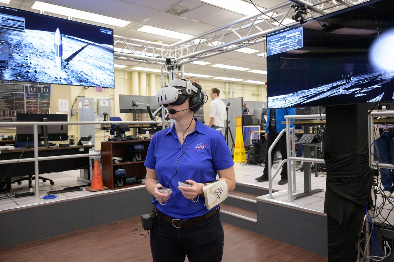
jsc2024e076628 – Tess Caswell, a crew stand-in for the Artemis III Virtual Reality Mini-Simulation, executes a moonwalk in the Prototype Immersive Technology (PIT) lab at NASA’s Johnson Space Center in Houston. The simulation was a test of using VR as a training method for flight controllers and science teams’ collaboration on science-focused traverses on the lunar surface. Credit: NASA/Robert Markowitz
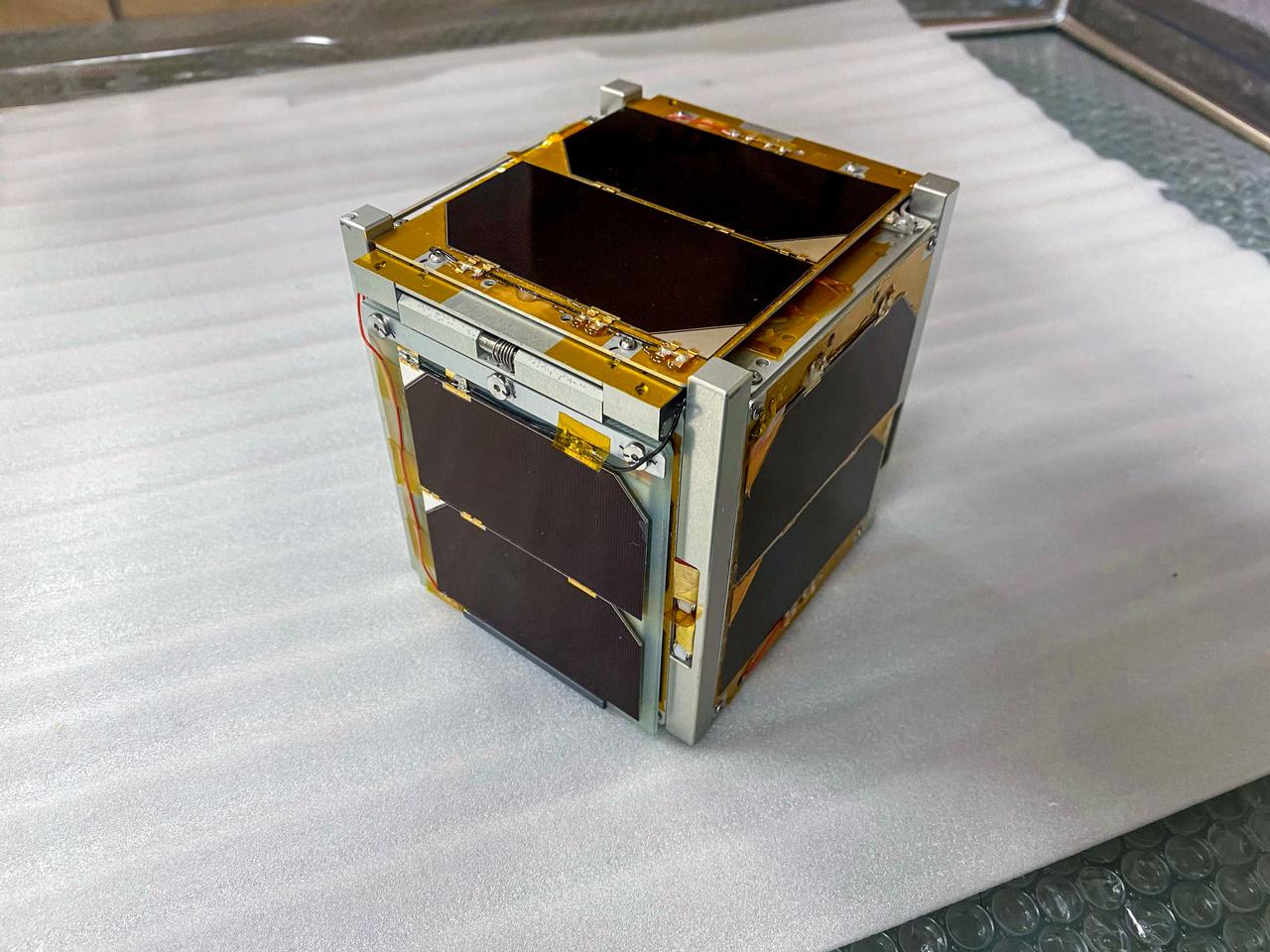
jsc2025e064343 (9/19/2023) --- Shown is the Space Tethered Autonomous Robotic Satellite Mini-elevator #2 - STARS-Me2 flight unit. STARS-Me2 is a 1U CubeSat developed by the Shizuoka University as part of the STARS project. The purpose of the STARS-Me2 mission is to demonstrate a technology to control orbital descending. This is achieved by step-by-step deployment and retrieval of a steel convex tether of approximately 10 meters...Image Credit: Shizuoka University
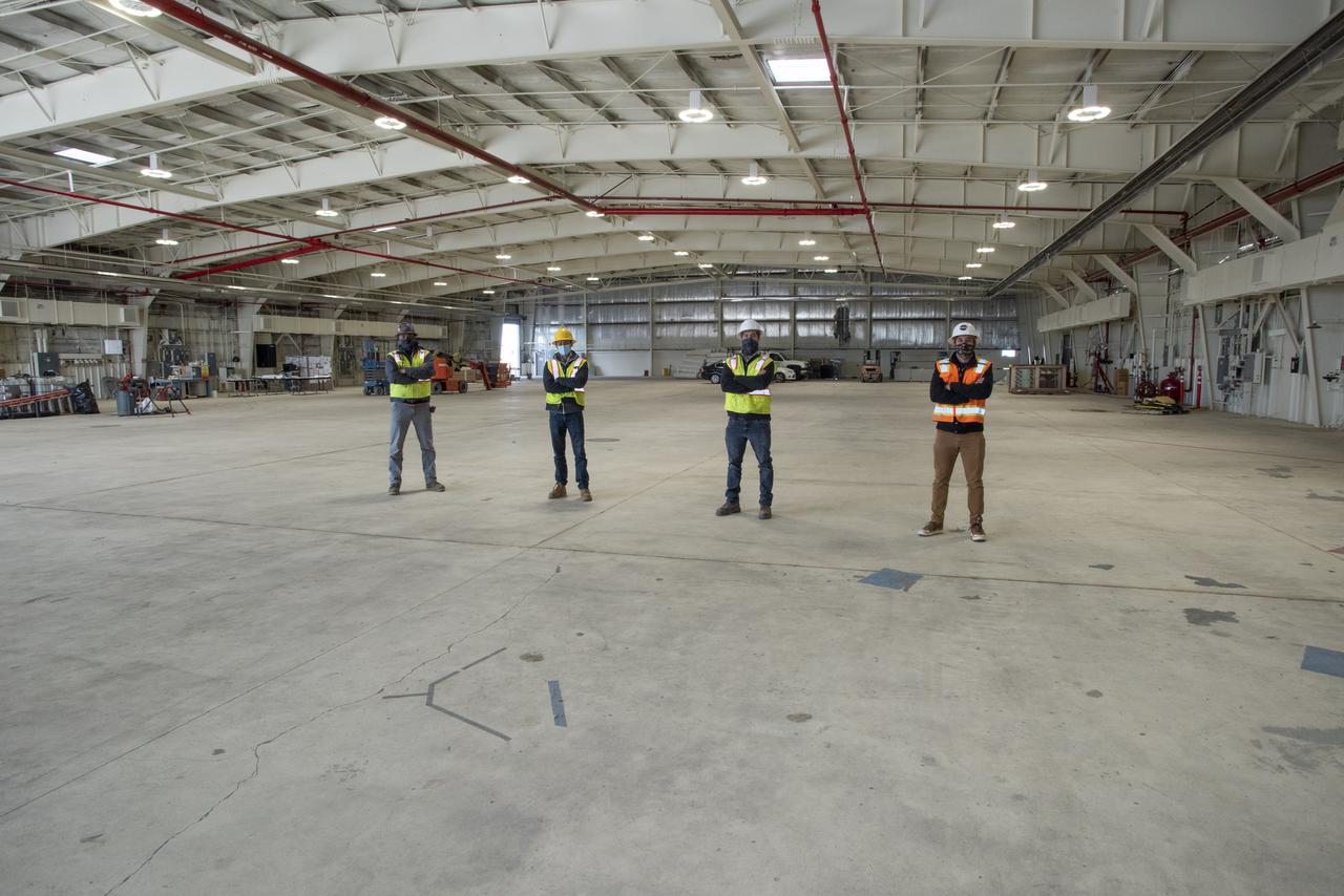
The future home of the X-59 Quiet SuperSonic Technology aircraft is taking shape at NASA's Armstrong Flight Research Center in Edwards, California. Some of the staff working on the project include from left to right Hector Mendoza, CJW/MZT Joint Venture site superintendent, Tim Nazer, CJW/MZT quality control manager, Collin Morris, CJW/MZT project manager and Bryan Watters, NASA civil/structural engineer and project manager.
iss068e020703 (Nov. 7, 2022) --- NASA astronaut and Expedition 68 Flight Engineer Nicole Mann works with a pair of free-flying, cube-shaped Astrobee robotic helpers inside the Kibo laboratory module. The toaster-sized, autonomous robots were demonstrating the use of a photogrammetric vision-based technology for guidance, navigation, and control as part of the Smartphone Vision Guidance Sensor experiment.
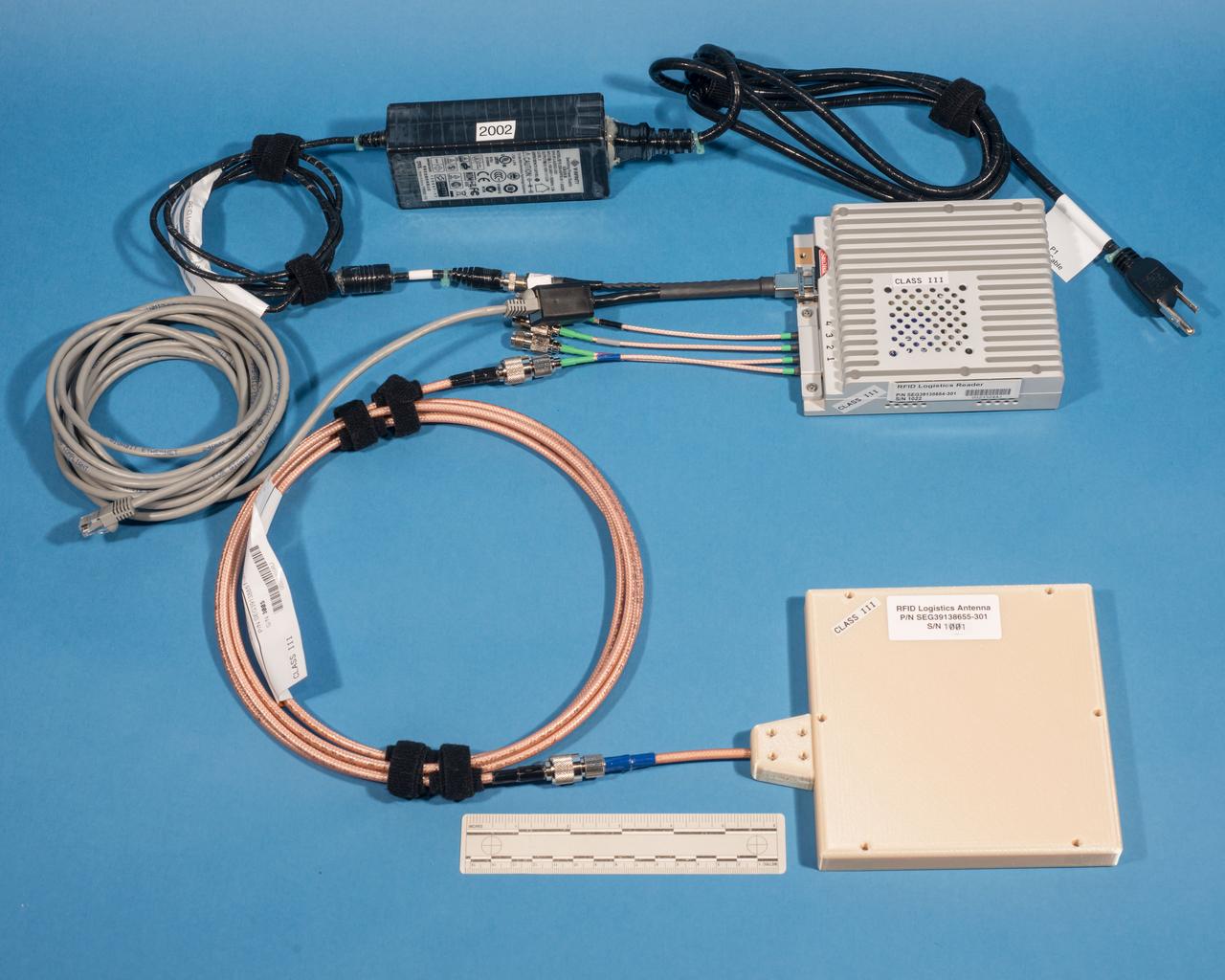
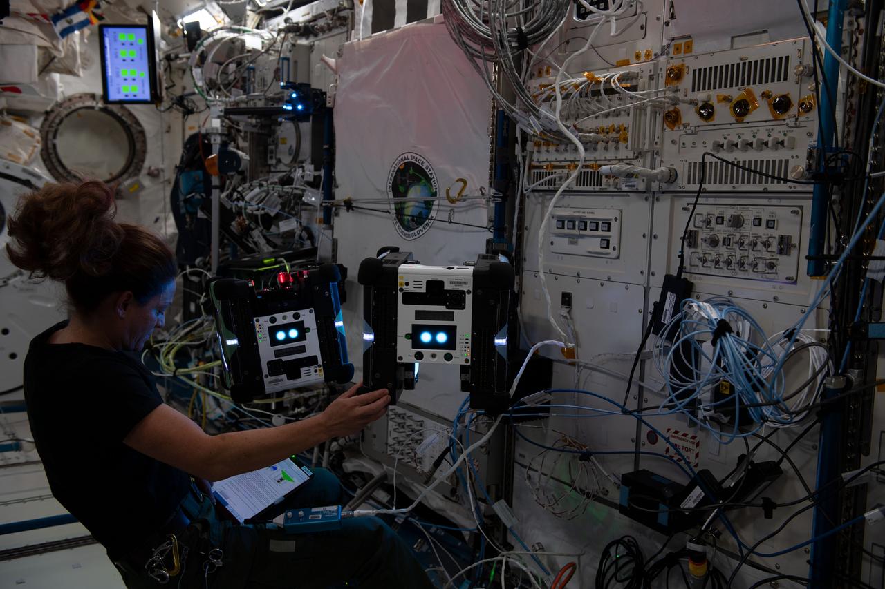
jsc2016e107373 (8/29/2016) --- Photographic documentation taken of REALM-1 (ISS OPNOM RFID Logistics) flight hardware in bldg 14 prior to delivery for launch. The RFID-Enabled Autonomous Logistics Management (REALM) (RFID Logistics Awareness) investigation tests a radio-based inventory control system to keep track of everything inside the football-field-sized ISS. Some aspects of the technology are commonly used on Earth, but other aspects are experimental in nature.
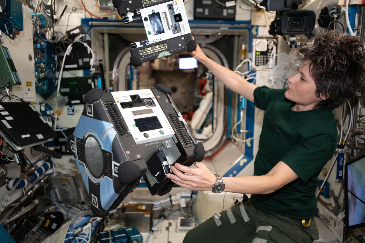
iss067e059514 (May 18, 2022) --- ESA (European Space Agency) astronaut and Expedition 67 Flight Engineer Samantha Cristoforetti monitors a pair of Astrobee robotic free-flyers performing autonomous maneuvers inside the International Space Station. The cube-shaped, toaster-sized robots are designed to help scientists and engineers develop and test technologies for use in microgravity to assist astronauts with routine chores, and give ground controllers additional eyes and ears on the space station.
iss068e020734 (Nov. 7, 2022) --- NASA astronaut and Expedition 68 Flight Engineer Nicole Mann poses with a pair of free-flying, cube-shaped Astrobee robotic helpers inside the Kibo laboratory module. The toaster-sized, autonomous robots were demonstrating the use of a photogrammetric vision-based technology for guidance, navigation, and control as part of the Smartphone Vision Guidance Sensor experiment.

Technology derived by NASA for monitoring control gyros in the Skylab program is directly applicable to the problems of fault detection of railroad wheel bearings. Marhsall Space Flight Center's scientists have developed a detection concept based on the fact that bearing defects excite resonant frequency of rolling elements of the bearing as they impact the defect. By detecting resonant frequency and subsequently analyzing the character of this signal, bearing defects may be detected and identified as to source.
In February 2021, NASA's Mars 2020 Perseverance rover and NASA's Ingenuity Mars Helicopter (shown in an artist's concept) will be the agency's two newest explorers on Mars. Both were named by students as part of an essay contest. Perseverance is the most sophisticated rover NASA has ever sent to Mars. Ingenuity, a technology experiment, will be the first aircraft to attempt controlled flight on another planet. Perseverance will arrive at Mars' Jezero Crater with Ingenuity attached to its belly. https://photojournal.jpl.nasa.gov/catalog/PIA23962
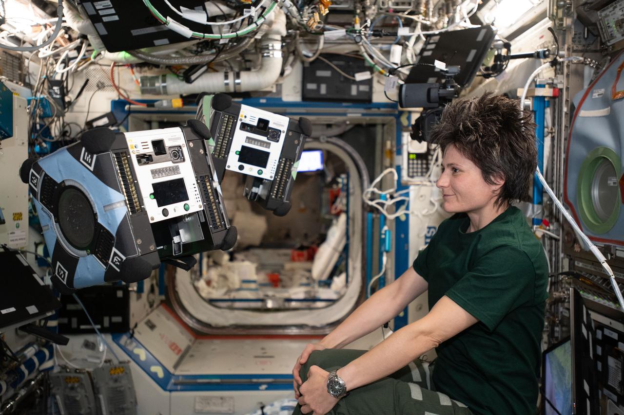
iss067e059518 (May 18, 2022) --- ESA (European Space Agency) astronaut and Expedition 67 Flight Engineer Samantha Cristoforetti monitors a pair of Astrobee robotic free-flyers performing autonomous maneuvers inside the International Space Station. The cube-shaped, toaster-sized robots are designed to help scientists and engineers develop and test technologies for use in microgravity to assist astronauts with routine chores, and give ground controllers additional eyes and ears on the space station.
jsc2024e016253 (1/8/2024) --- The Nano Particle Haloing Suspension payload undergoes a fitting test at NASA's Marshall Space Flight Center in the Microgravity Science Glovebox replica. This payload tests controlled assembly of nanoparticles in a solution of zirconia and titanium-dioxide coated silica. Effective demonstration could lead to applications in an enhanced solar cell generation technology known as quantum-dot solar synthesis. Image courtesy of the University of Louisville.
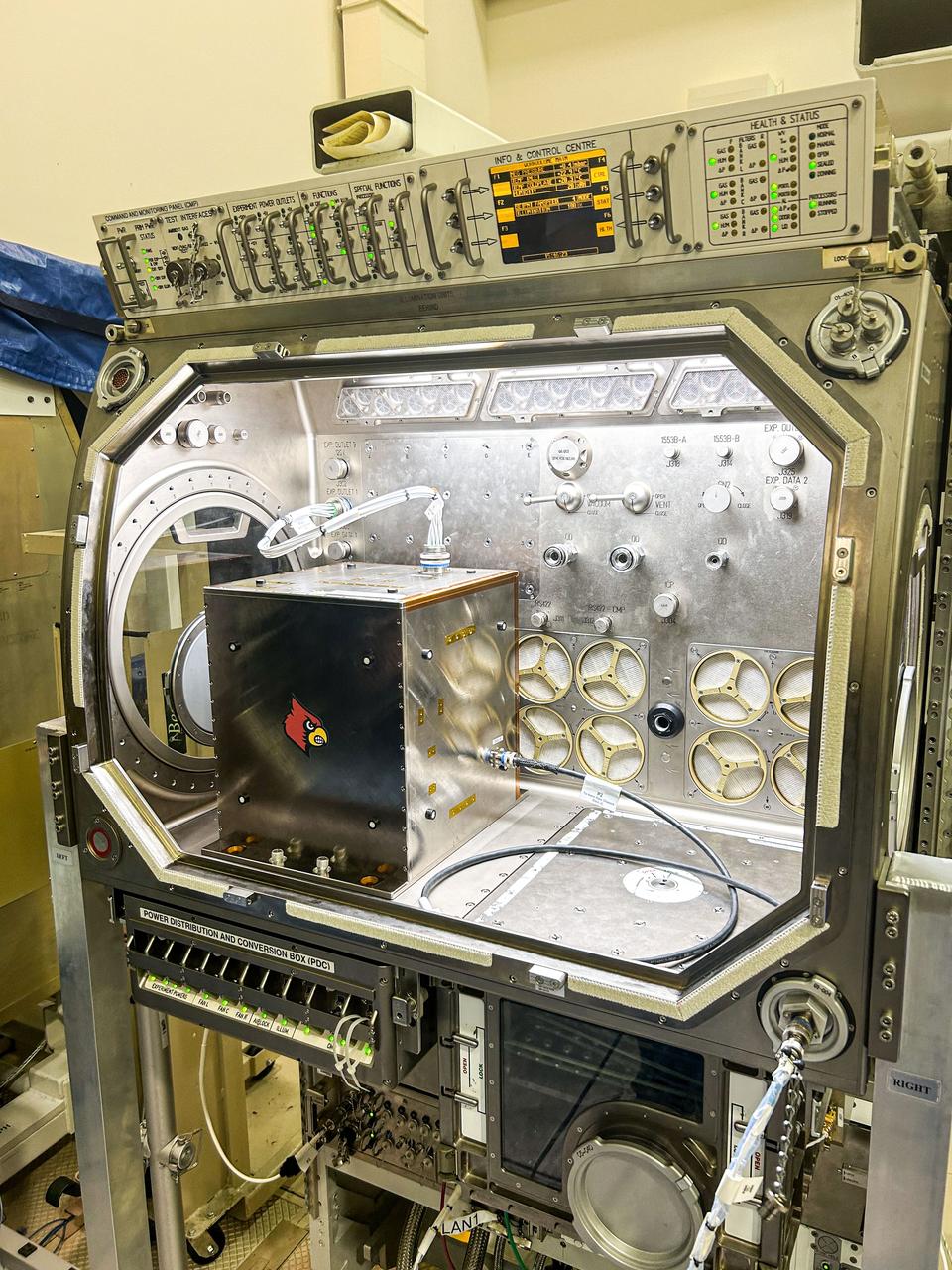
jsc2023e010168 (1/30/2023) --- CapiSorb Visible System flight unit contactor in N240 room 133B. The CapiSorb Visible System will be launched on SpaceX CRS-27 in March 2023 to the International Space Station to demonstrate a liquid sorbent-based system that leverages the advantages of liquid control through capillary action to remove carbon dioxide from crewed atmospheres...Capillary wedges in the CapiSorb Visible System Contactor, shown here preflight, control and passively transport viscous liquid in microgravity in order to demonstrate capabilities needed for future liquid carbon dioxide removal technologies. The CapiSorb Visible System investigation demonstrates a liquid control using capillary forces, over a range of properties that are characteristic of liquids which absorb carbon dioxide. Image courtesy of NASA's Ames Research Cente
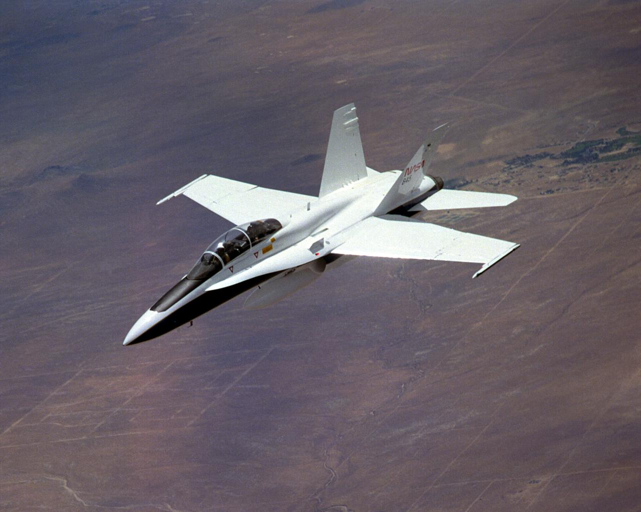
The National Aeronautics and Space Administration's Systems Research Aircraft (SRA), a highly modified F-18 jet fighter, during a research flight. The former Navy aircraft was flown by NASA's Dryden Flight Research Center at Edwards Air Force Base, California, to evaluate a number of experimental aerospace technologies in a multi-year, joint NASA/DOD/industry program. Among the more than 20 experiments flight-tested were several involving fiber optic sensor systems. Experiments developed by McDonnell-Douglas and Lockheed-Martin centered on installation and maintenace techniques for various types of fiber-optic hardware proposed for use in military and commercial aircraft, while a Parker-Hannifin experiment focused in alternative fiber-optic designs for position measurement sensors as well as operational experience in handling optical sensor systems. Other experiments flown on this testbed aircraft included electronically-controlled control surface actuators, flush air data collection systems, "smart" skin antennae and laser-based systems. Incorporation of one or more of these technologies in future aircraft and spacecraft could result in signifigant savings in weight, maintenance and overall cost.
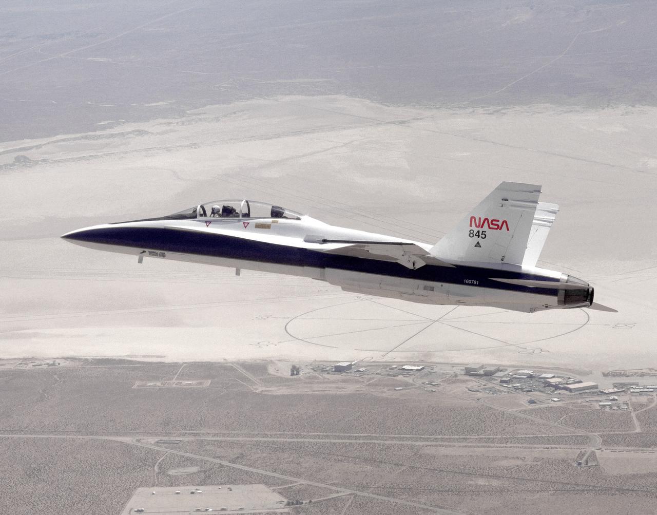
The National Aeronautics and Space Administration's Systems Research Aircraft (SRA), a highly modified F-18 jet fighter, on an early research flight over Rogers Dry Lake. The former Navy aircraft was flown by NASA's Dryden Flight Research Center at Edwards Air Force Base, California, to evaluate a number of experimental aerospace technologies in a multi-year, joint NASA/DOD/industry program. Among the more than 20 experiments flight-tested were several involving fiber optic sensor systems. Experiments developed by McDonnell-Douglas and Lockheed-Martin centered on installation and maintenace techniques for various types of fiber-optic hardware proposed for use in military and commercial aircraft, while a Parker-Hannifin experiment focused on alternative fiber-optic designs for postion measurement sensors as well as operational experience in handling optical sensor systems. Other experiments flown on this testbed aircraft included electronically-controlled control surface actuators, flush air data collection systems, "smart" skin antennae and laser-based systems. Incorporation of one or more of these technologies in future aircraft and spacecraft could result in signifigant savings in weight, maintenance and overall cost.
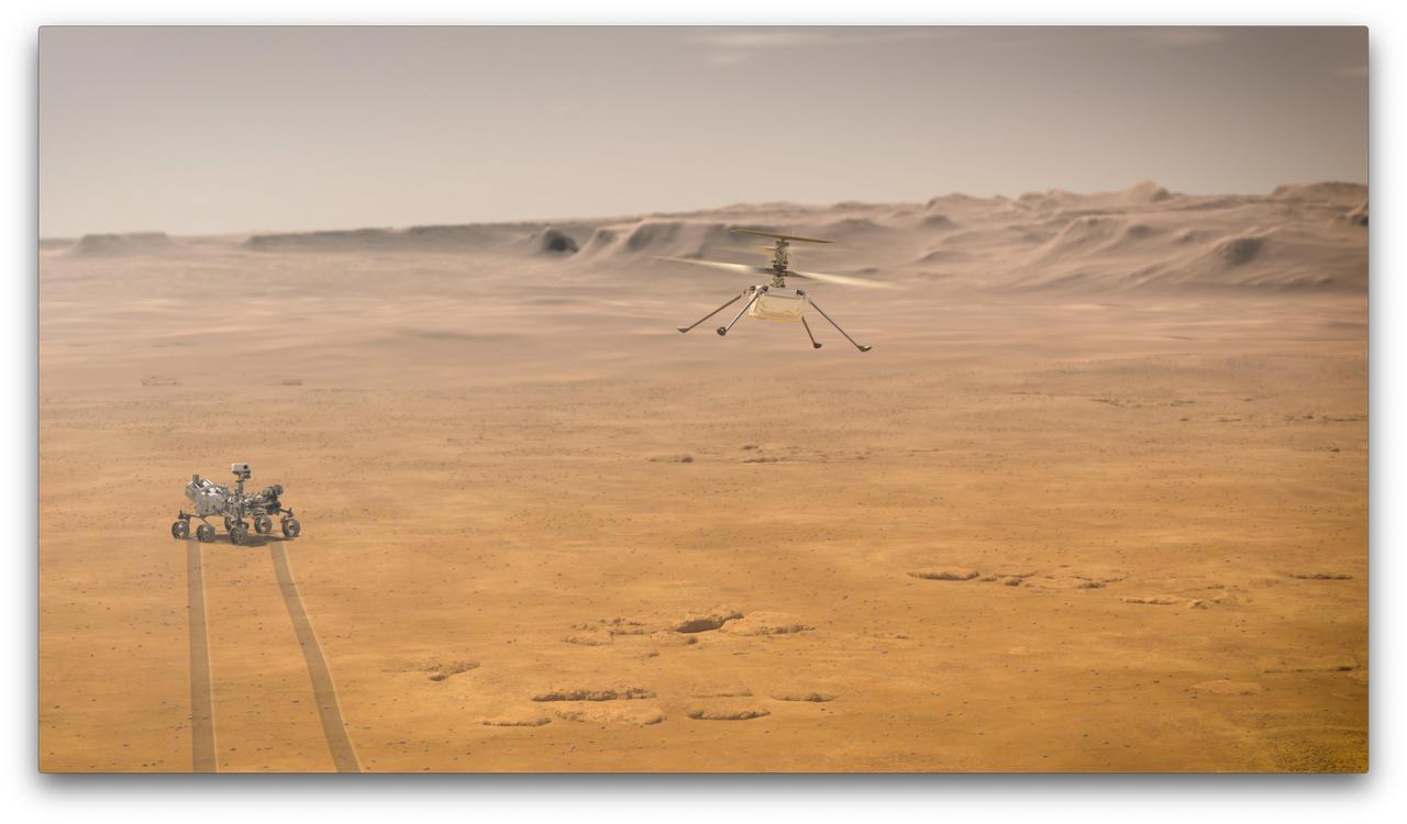
When NASA's Ingenuity Mars Helicopter attempts its first test flight on the Red Planet, the agency's Mars 2020 Perseverance rover will be close by, as seen in this artist's concept. Ingenuity, a technology experiment, will be the first aircraft to attempt controlled flight on another planet. When it attempts its test flights on Mars in spring 2021, Ingenuity will remain within a 0.6-mile (1-kilometer) radius of Perseverance so it can communicate wirelessly with the rover. Perseverance then communicates with relay orbiters around Mars that send the signal back to Earth. https://photojournal.jpl.nasa.gov/catalog/PIA23963

The Marshall Space Flight Center (MSFC) is responsible for designing and building the life support systems that will provide the crew of the International Space Station (ISS) a comfortable environment in which to live and work. Scientists and engineers at the MSFC are working together to provide the ISS with systems that are safe, efficient, and cost-effective. These compact and powerful systems are collectively called the Environmental Control and Life Support Systems, or simply, ECLSS. This photograph shows the development Water Processor located in two racks in the ECLSS test area at the Marshall Space Flight Center. Actual waste water, simulating Space Station waste, is generated and processed through the hardware to evaluate the performance of technologies in the flight Water Processor design.
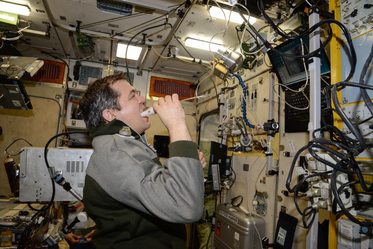
iss047e136530 (6/2/2016) --- A view of Cosmonaut Oleg Skripochka, during a BIMS Experiment session in the Service module aboard the International Space Station (ISS). The Study of Processes for Informational Support of In-Flight Medical Support using an Onboard Medical Information System Integrated into the Information Control System of the ISS Russian Segment (BIMS) uses telemedicine technologies to collect information by non-contact means from the ear, nose, and throat (ENT), gums, teeth, and small areas of skin from International Space Station (ISS) crews for medical support of manned spaceflights and in-flight biomedical research.
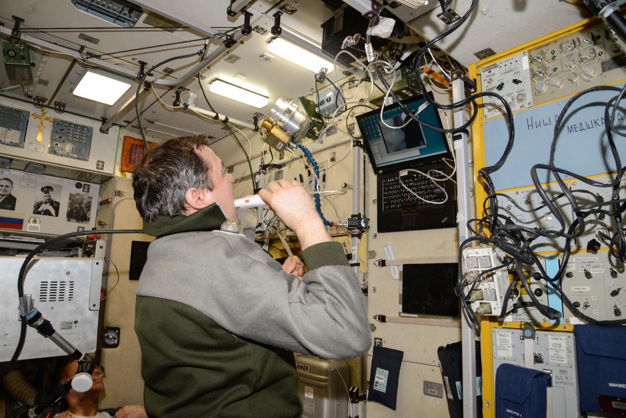
iss047e136529 (6/2/2016) --- A view of Cosmonaut Oleg Skripochka, during a BIMS Experiment session in the Service module aboard the International Space Station (ISS). The Study of Processes for Informational Support of In-Flight Medical Support using an Onboard Medical Information System Integrated into the Information Control System of the ISS Russian Segment (BIMS) uses telemedicine technologies to collect information by non-contact means from the ear, nose, and throat (ENT), gums, teeth, and small areas of skin from International Space Station (ISS) crews for medical support of manned spaceflights and in-flight biomedical research.

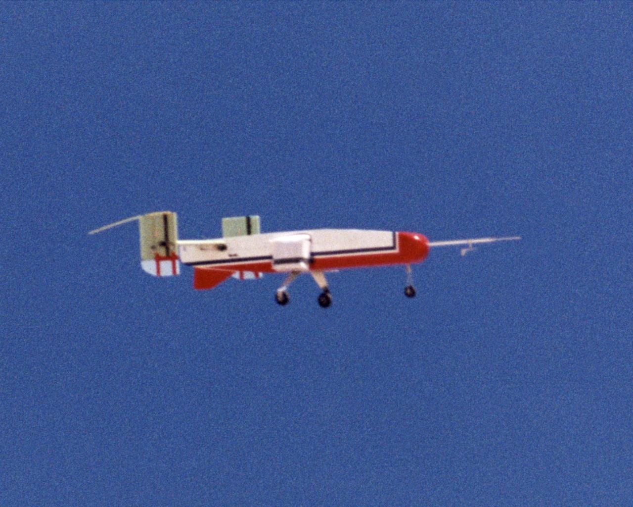
The second X-45A Unmanned Combat Air Vehicle (UCAV) technology demonstrator completed its first flight on November 21, 2002, after taking off from a dry lakebed at NASA's Dryden Flight Research Center, Edwards Air Force Base, California. X-45A vehicle two flew for approximately 30 minutes and reached an airspeed of 195 knots and an altitude of 7500 feet. This flight validated the functionality of the UCAV flight software on the second air vehicle. Dryden is supporting the DARPA/Boeing team in the design, development, integration, and demonstration of the critical technologies, processes, and system attributes leading to an operational UCAV system. Dryden support of the X-45A demonstrator system includes analysis, component development, simulations, ground and flight tests.
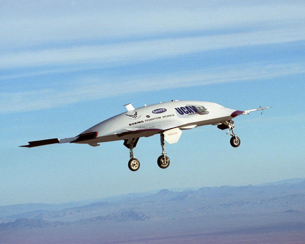
The second X-45A Unmanned Combat Air Vehicle (UCAV) technology demonstrator completed its first flight on November 21, 2002, after taking off from a dry lakebed at NASA's Dryden Flight Research Center, Edwards Air Force Base, California. X-45A vehicle two flew for approximately 30 minutes and reached an airspeed of 195 knots and an altitude of 7500 feet. This flight validated the functionality of the UCAV flight software on the second air vehicle. Dryden is supporting the DARPA/Boeing team in the design, development, integration, and demonstration of the critical technologies, processes, and system attributes leading to an operational UCAV system. Dryden support of the X-45A demonstrator system includes analysis, component development, simulations, ground and flight tests.
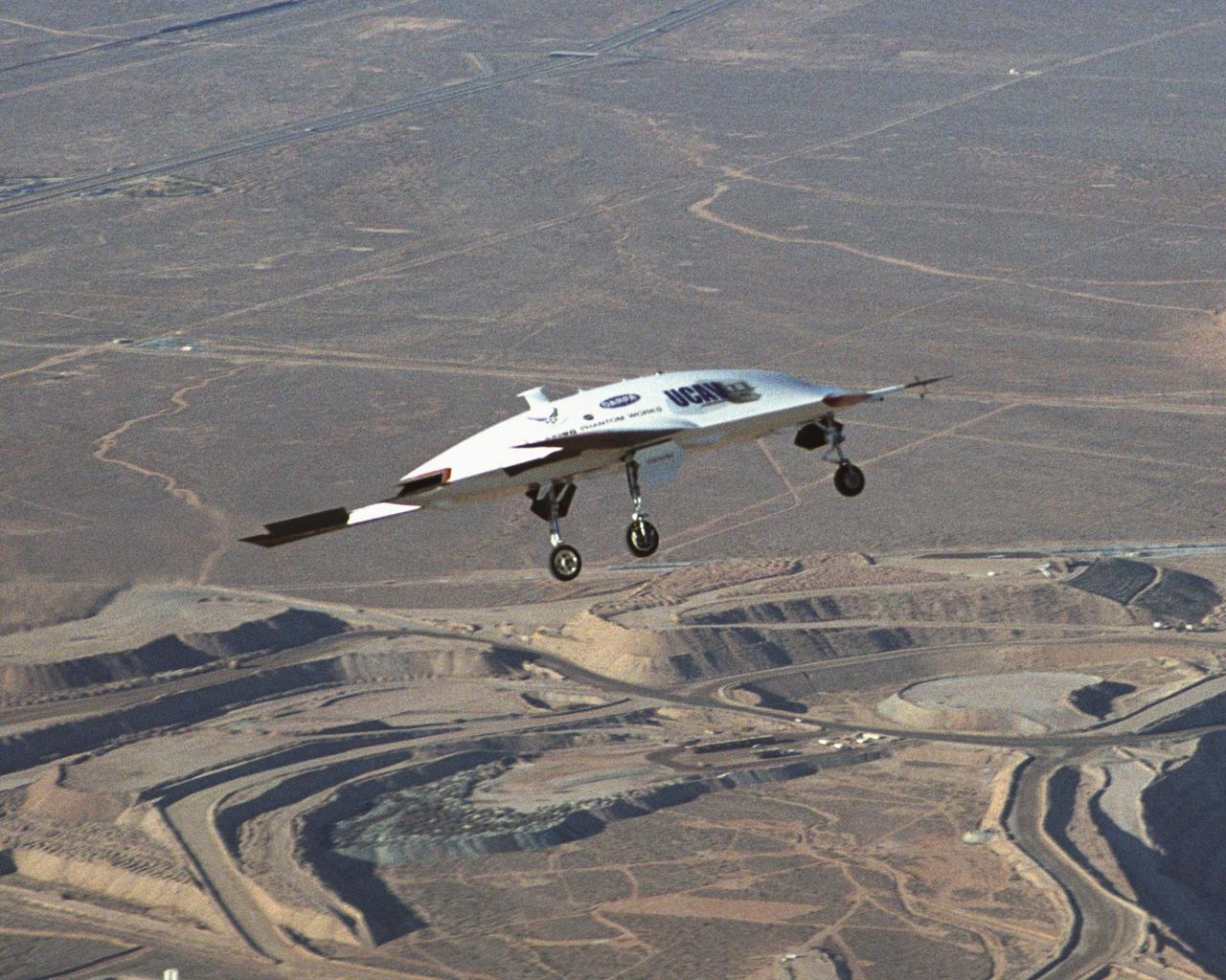
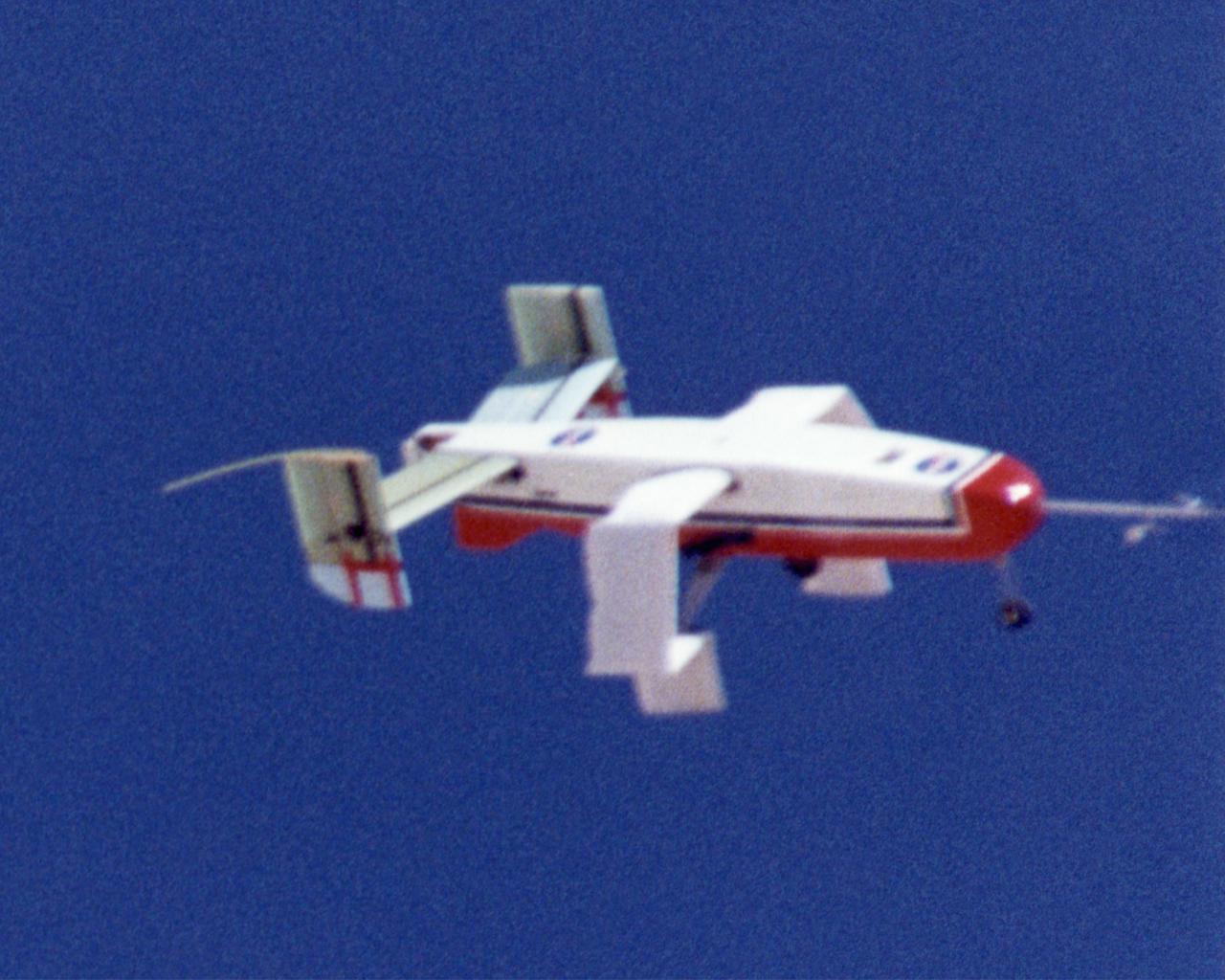
The second X-45A Unmanned Combat Air Vehicle (UCAV) technology demonstrator completed its first flight on November 21, 2002, after taking off from a dry lakebed at NASA's Dryden Flight Research Center, Edwards Air Force Base, California. X-45A vehicle two flew for approximately 30 minutes and reached an airspeed of 195 knots and an altitude of 7500 feet. This flight validated the functionality of the UCAV flight software on the second air vehicle. Dryden is supporting the DARPA/Boeing team in the design, development, integration, and demonstration of the critical technologies, processes, and system attributes leading to an operational UCAV system. Dryden support of the X-45A demonstrator system includes analysis, component development, simulations, ground and flight tests.
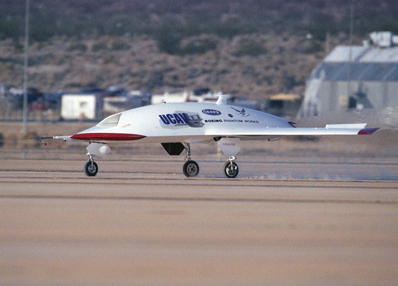
The second X-45A Unmanned Combat Air Vehicle (UCAV) technology demonstrator completed its first flight on November 21, 2002, after taking off from a dry lakebed at NASA's Dryden Flight Research Center, Edwards Air Force Base, California. X-45A vehicle two flew for approximately 30 minutes and reached an airspeed of 195 knots and an altitude of 7500 feet. This flight validated the functionality of the UCAV flight software on the second air vehicle. Dryden is supporting the DARPA/Boeing team in the design, development, integration, and demonstration of the critical technologies, processes, and system attributes leading to an operational UCAV system. Dryden support of the X-45A demonstrator system includes analysis, component development, simulations, ground and flight tests.
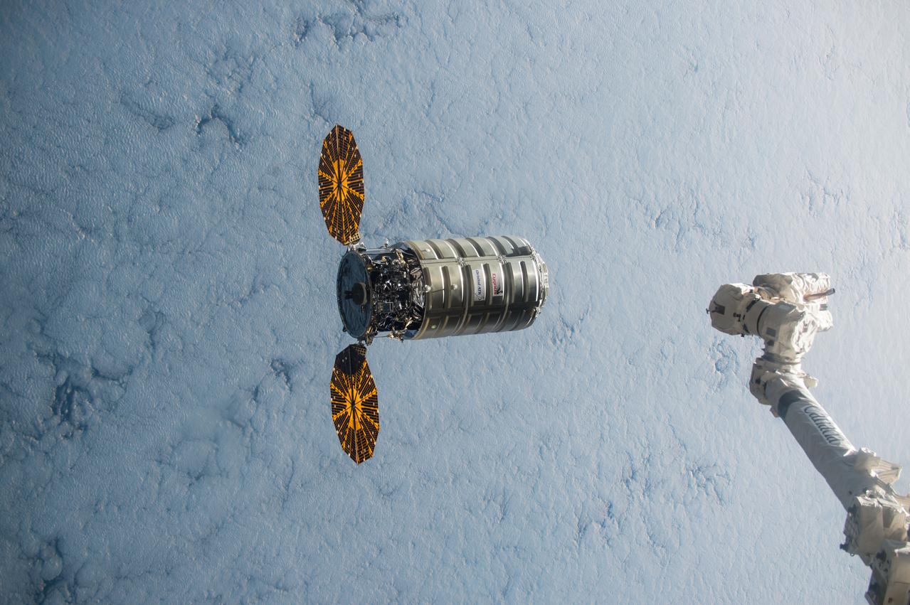
ISS045e176110 (12/09/2015) --- Using the International Space Station’s robotic arm, Canadarm2 (right) NASA Flight Engineer Kjell Lindgren prepares to capture Orbital ATK’s Cygnus cargo vehicle Dec. 09, 2015. The space station crew and the robotics officer in mission control in Houston will position Cygnus for installation to the orbiting laboratory’s Earth-facing port of the Unity module. Among the more than 7,000 pounds of supplies aboard Cygnus are numerous science and research investigations and technology demonstrations, including a new life science facility that will support studies on cell cultures, bacteria and other microorganisms; a microsatellite deployer and the first microsatellite that will be deployed from the space station; several other educational and technology demonstration CubeSats; and experiments that will study the behavior of gases and liquids, clarify the thermo-physical properties of molten steel, and evaluate flame-resistant textiles.
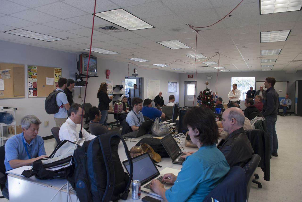
Engineers and controllers in a mobile control room prepare for flight number 15 of NASA's Project Morpheus prototype lander at the north end of the Shuttle Landing Facility, or SLF, at NASA’s Kennedy Space Center in Florida. The lander will take off from the ground over a flame trench and use its autonomous landing and hazard avoidance technology, or ALHAT sensors, to survey the hazard field to determine safe landing sites. Project Morpheus tests NASA’s ALHAT and an engine that runs on liquid oxygen and methane, which are green propellants. These new capabilities could be used in future efforts to deliver cargo to planetary surfaces. Project Morpheus is being managed under the Advanced Exploration Systems, or AES, Division in NASA’s Human Exploration and Operations Mission Directorate.
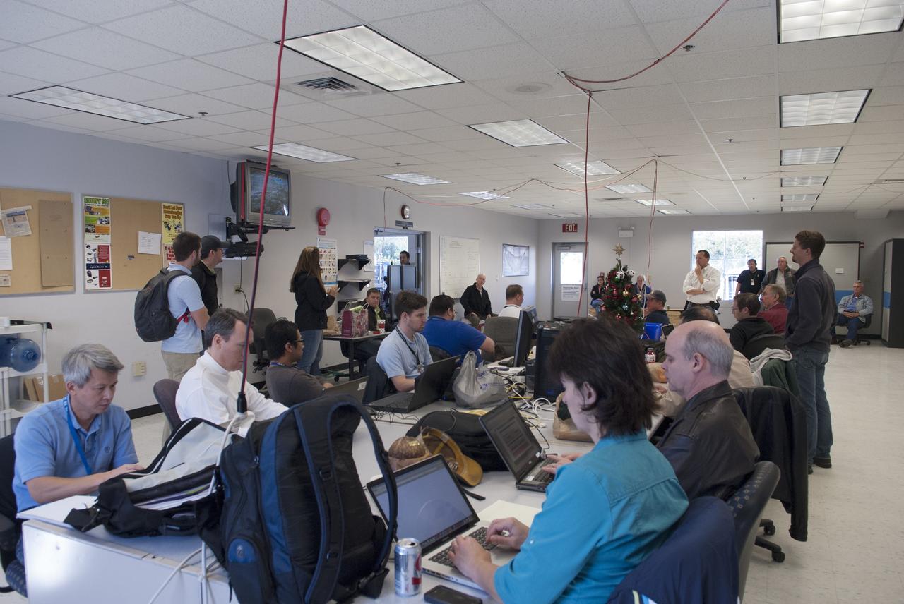
CAPE CANAVERAL, Fla. – Engineers and controllers in a mobile control room prepare for flight number 15 of NASA's Project Morpheus prototype lander at the north end of the Shuttle Landing Facility, or SLF, at NASA’s Kennedy Space Center in Florida. The lander will take off from the ground over a flame trench and use its autonomous landing and hazard avoidance technology, or ALHAT sensors, to survey the hazard field to determine safe landing sites. Project Morpheus tests NASA’s ALHAT and an engine that runs on liquid oxygen and methane, which are green propellants. These new capabilities could be used in future efforts to deliver cargo to planetary surfaces. Project Morpheus is being managed under the Advanced Exploration Systems, or AES, Division in NASA’s Human Exploration and Operations Mission Directorate. For more information on Project Morpheus, visit http://morpheuslander.jsc.nasa.gov/. Photo credit: NASA/Jim Grossmann
Proteus DSA control room in Mojave, CA (L to R) Jean-Pierre Soucy; Amphitech International Software engineer Craig Bomben; NASA Dryden Test Pilot Pete Siebold; (with headset, at computer controls) Scaled Composites pilot Bob Roehm; New Mexico State University (NMSU) UAV Technical Analysis Application Center (TAAC) Chuck Coleman; Scaled Composites Pilot Kari Sortland; NMSU TAAC Russell Wolfe; Modern Technology Solutions, Inc. Scaled Composites' unique tandem-wing Proteus was the testbed for a series of UAV collision-avoidance flight demonstrations. An Amphitech 35GHz radar unit installed below Proteus' nose was the primary sensor for the Detect, See and Avoid tests.
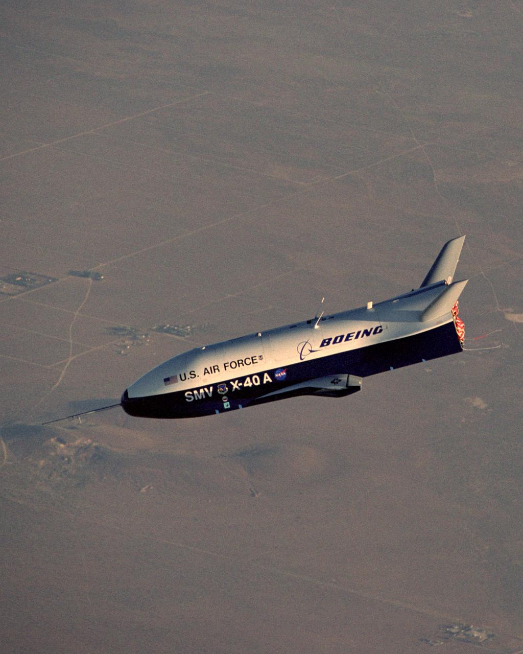
X-40A Free Flight #5. The unpowered X-40A, an 85 percent scale risk reduction version of the proposed X-37, proved the capability of an autonomous flight control and landing system in a series of glide flights at NASA's Dryden Flight Research Center in California. NASA's Marshall Space Flight Center in Huntsville, Alabama, manages the X-37 project. At Dryden, the X-40A underwent a series of ground and air tests to reduce possible risks to the larger X-37, including drop tests from a helicopter to check guidance and navigation systems planned for use in the X-37. The X-37 is designed to demonstrate technologies in the orbital and reentry environments for next-generation reusable launch vehicles that will increase both safety and reliability, while reducing launch costs from $10,000 per pound to $1,000 per pound.
X-40A Free Flight #5. The unpowered X-40A, an 85 percent scale risk reduction version of the proposed X-37, proved the capability of an autonomous flight control and landing system in a series of glide flights at NASA's Dryden Flight Research Center in California. NASA's Marshall Space Flight Center in Huntsville, Alabama, manages the X-37 project. At Dryden, the X-40A underwent a series of ground and air tests to reduce possible risks to the larger X-37, including drop tests from a helicopter to check guidance and navigation systems planned for use in the X-37. The X-37 is designed to demonstrate technologies in the orbital and reentry environments for next-generation reusable launch vehicles that will increase both safety and reliability, while reducing launch costs from $10,000 per pound to $1,000 per pound.
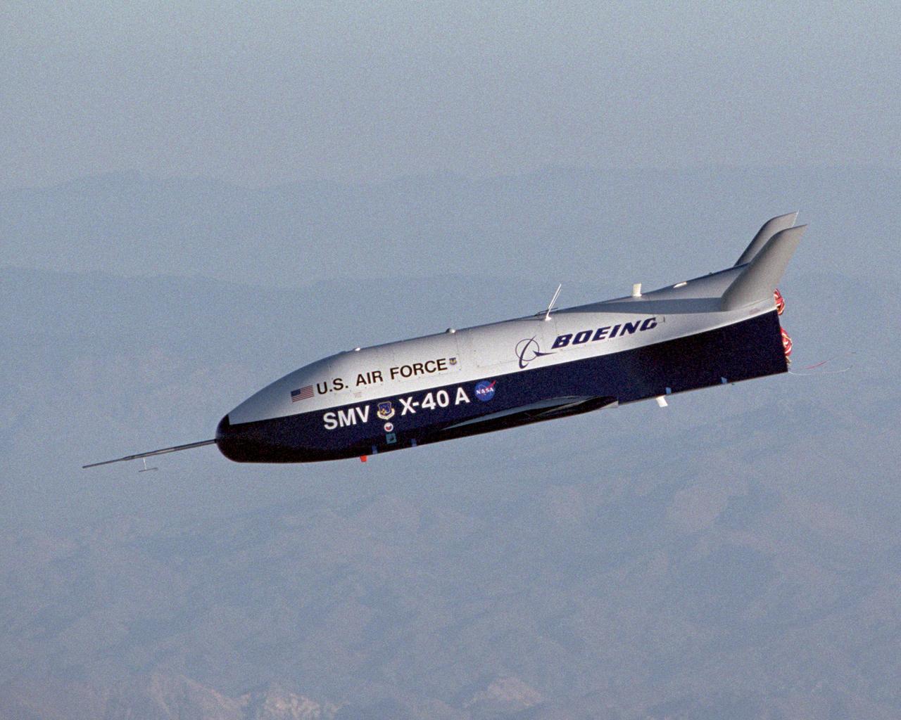
X-40A Free Flight #5. The unpowered X-40A, an 85 percent scale risk reduction version of the proposed X-37, proved the capability of an autonomous flight control and landing system in a series of glide flights at NASA's Dryden Flight Research Center in California. NASA's Marshall Space Flight Center in Huntsville, Alabama, manages the X-37 project. At Dryden, the X-40A underwent a series of ground and air tests to reduce possible risks to the larger X-37, including drop tests from a helicopter to check guidance and navigation systems planned for use in the X-37. The X-37 is designed to demonstrate technologies in the orbital and reentry environments for next-generation reusable launch vehicles that will increase both safety and reliability, while reducing launch costs from $10,000 per pound to $1,000 per pound.
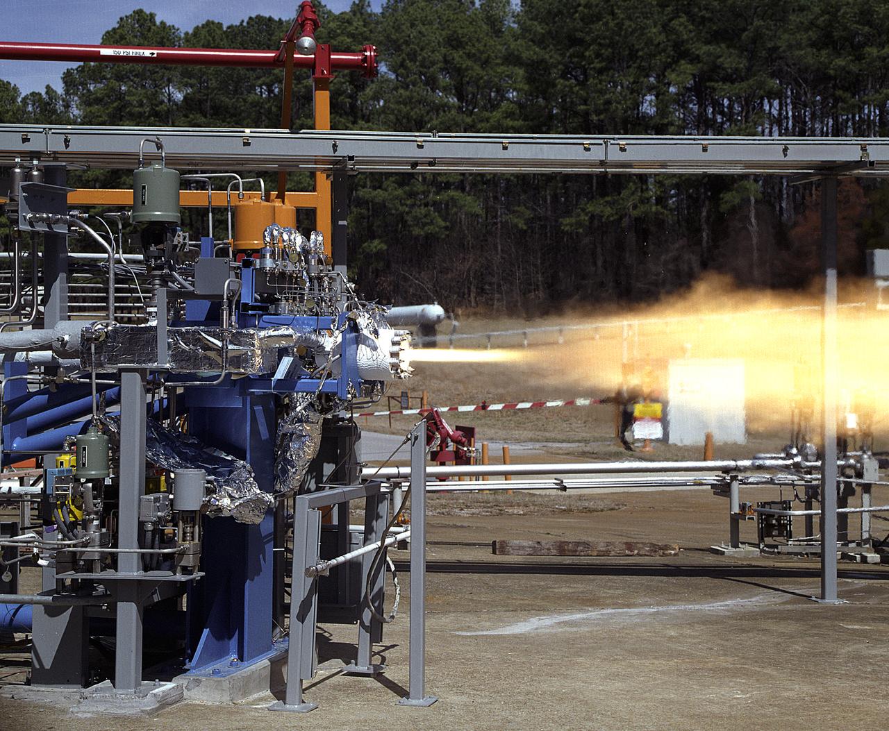
NASA's Marshall Space Flight Center (MSFC) in Huntsville, Alabama, has begun a series of engine tests on the Reaction Control Engine developed by TRW Space and Electronics for NASA's Space Launch Initiative (SLI). SLI is a technology development effort aimed at improving the safety, reliability, and cost effectiveness of space travel for reusable launch vehicles. The engine in this photo, the first engine tested at MSFC that includes SLI technology, was tested for two seconds at a chamber pressure of 185 pounds per square inch absolute (psia). Propellants used were liquid oxygen as an oxidizer and liquid hydrogen as fuel. Designed to maneuver vehicles in orbit, the engine is used as an auxiliary propulsion system for docking, reentry, fine-pointing, and orbit transfer while the vehicle is in orbit. The Reaction Control Engine has two unique features. It uses nontoxic chemicals as propellants, which creates a safer environment with less maintenance and quicker turnaround time between missions, and it operates in dual thrust modes, combining two engine functions into one engine. The engine operates at both 25 and 1,000 pounds of force, reducing overall propulsion weight and allowing vehicles to easily maneuver in space. The force of low level thrust allows the vehicle to fine-point maneuver and dock, while the force of the high level thrust is used for reentry, orbital transfer, and course positioning.
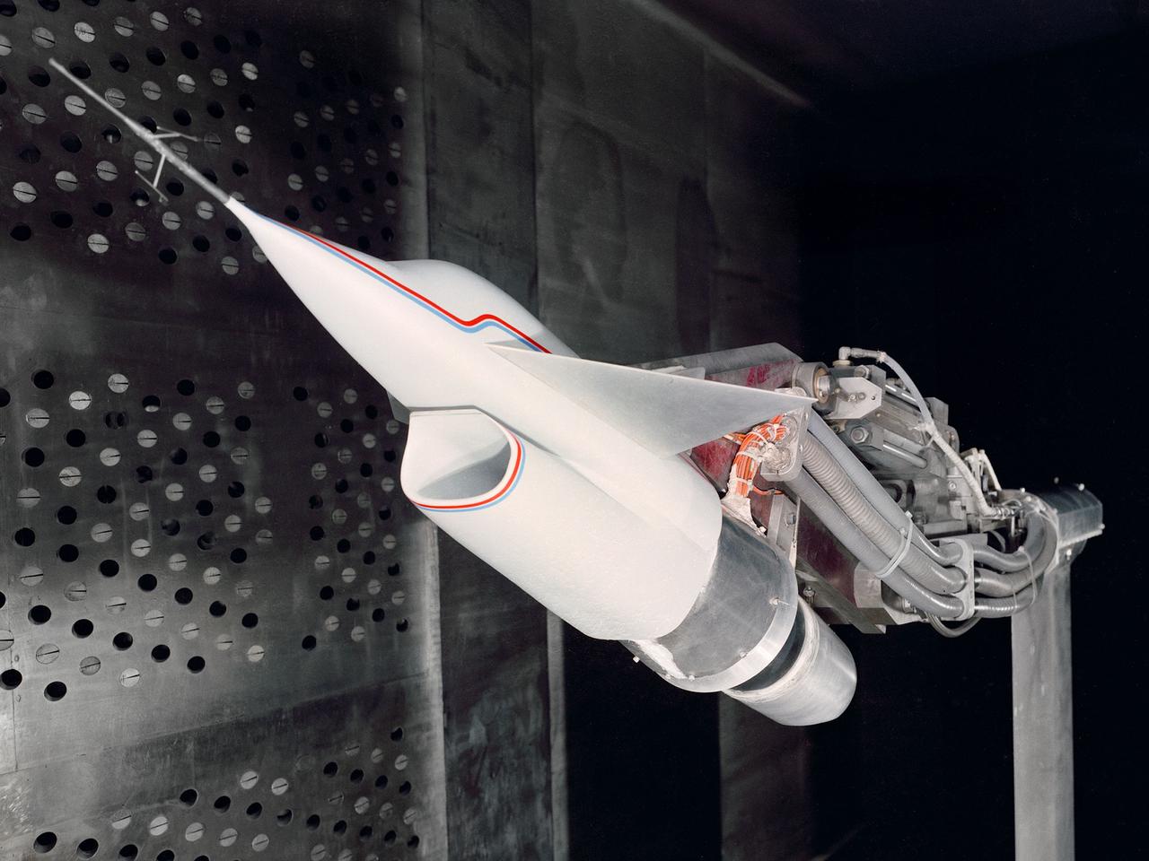
A Highly Maneuverable Aircraft Technology (HiMAT) inlet model installed in the test section of the 8- by 6-Foot Supersonic Wind Tunnel at the National Aeronautics and Space Administration (NASA) Lewis Research Center. Engineers at the Ames Research Center, Dryden Flight Research Center, and Rockwell International designed two pilotless subscale HiMAT vehicles in the mid-1970s to study new design concepts for fighter aircraft in the transonic realm without risking the lives of test pilots. The aircraft used sophisticated technologies such as advanced aerodynamics, composite materials, digital integrated propulsion control, and digital fly-by-wire control systems. In late 1977 NASA Lewis studied the HiMAT’s General Electric J85-21 jet engine in the Propulsion Systems Laboratory. The researchers charted the inlet quality with various combinations anti-distortion screens. HiMAT employed a relatively short and curved inlet compared to actual fighter jets. In the spring of 1979, Larry Smith led an in-depth analysis of the HiMAT inlet in the 8- by 6 tunnel. The researchers installed vortex generators to battle flow separation in the diffuser. The two HiMAT aircraft performed 11 hours of flying over the course of 26 missions from mid-1979 to January 1983 at Dryden and Ames. Although the HiMAT vehicles were considered to be overly complex and expensive, the program yielded a wealth of data that would validate computer-based design tools.
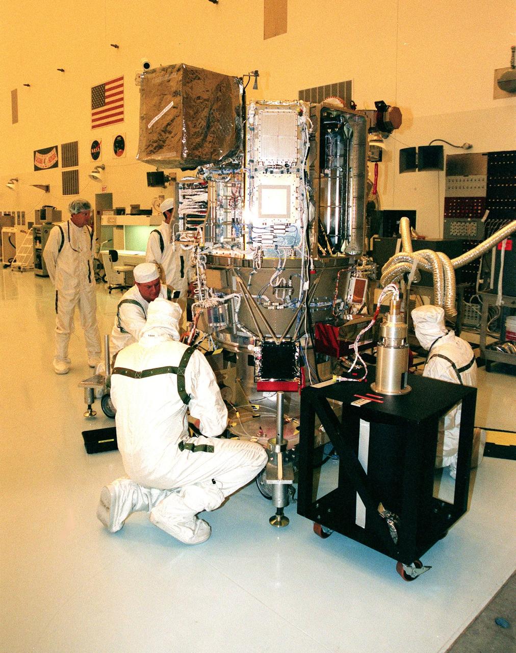
KENNEDY SPACE CENTER, FLA. -- Workers in the Payload Hazardous Servicing Facility check out Deep Space 1 to prepare it for launch aboard a Boeing Delta 7326 rocket in October. The first flight in NASA's New Millennium Program, Deep Space 1 is designed to validate 12 new technologies for scientific space missions of the next century. Onboard experiments include an ion propulsion engine and software that tracks celestial bodies so the spacecraft can make its own navigation decisions without the intervention of ground controllers. Most of its mission objectives will be completed within the first two months. A near-Earth asteroid, 1992 KD, has also been selected for a possible flyby
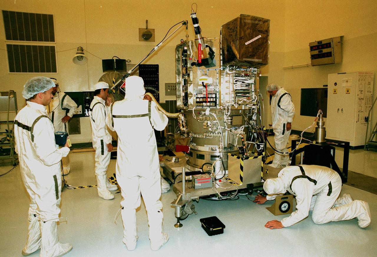
KENNEDY SPACE CENTER, FLA. -- Workers in the Payload Hazardous Servicing Facility prepare Deep Space 1 for launch aboard a Boeing Delta 7326 rocket in October. The first flight in NASA's New Millennium Program, Deep Space 1 is designed to validate 12 new technologies for scientific space missions of the next century. Onboard experiments include an ion propulsion engine and software that tracks celestial bodies so the spacecraft can make its own navigation decisions without the intervention of ground controllers. Most of its mission objectives will be completed within the first two months. A near-Earth asteroid, 1992 KD, has also been selected for a possible flyby
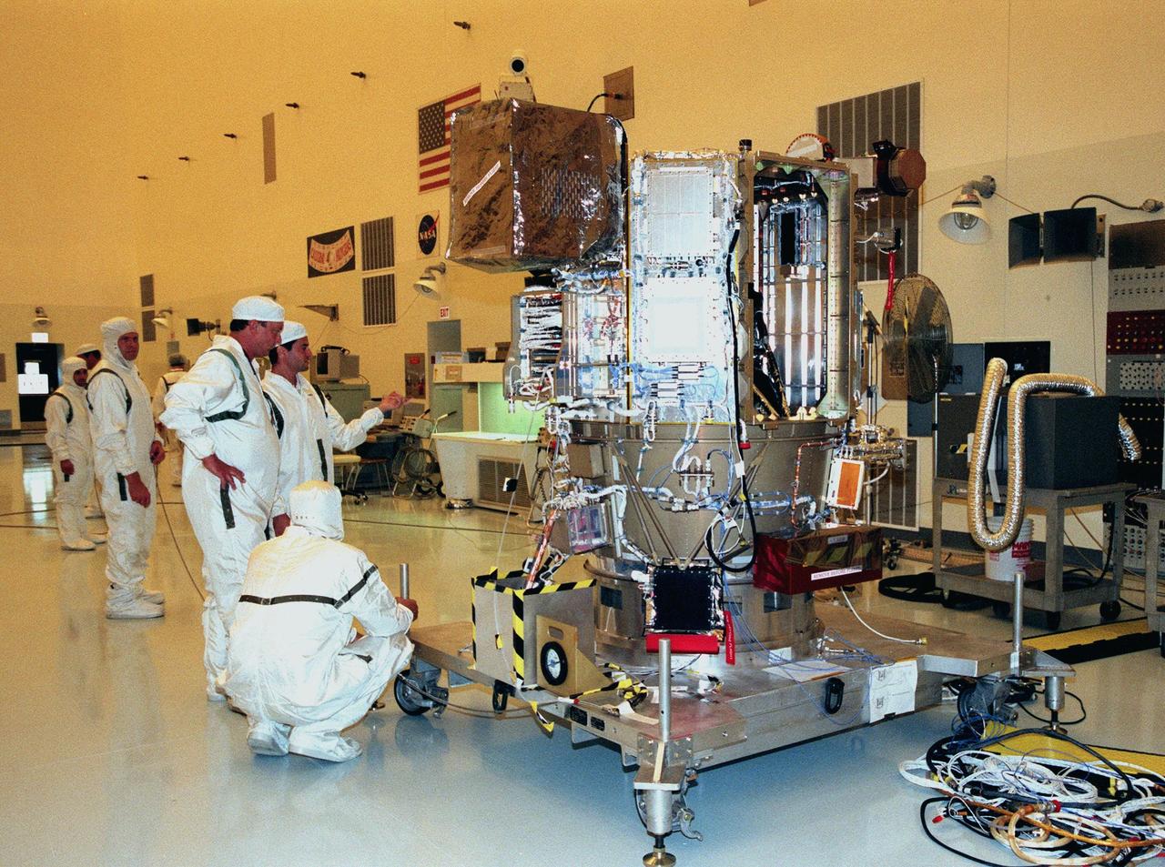
KENNEDY SPACE CENTER, FLA. -- Workers in the Payload Hazardous Servicing Facility test equipment on Deep Space 1 to prepare it for launch aboard a Boeing Delta 7326 rocket in October. The first flight in NASA's New Millennium Program, Deep Space 1 is designed to validate 12 new technologies for scientific space missions of the next century. Onboard experiments include an ion propulsion engine and software that tracks celestial bodies so the spacecraft can make its own navigation decisions without the intervention of ground controllers. Most of its mission objectives will be completed within the first two months. A near-Earth asteroid, 1992 KD, has also been selected for a possible flyby
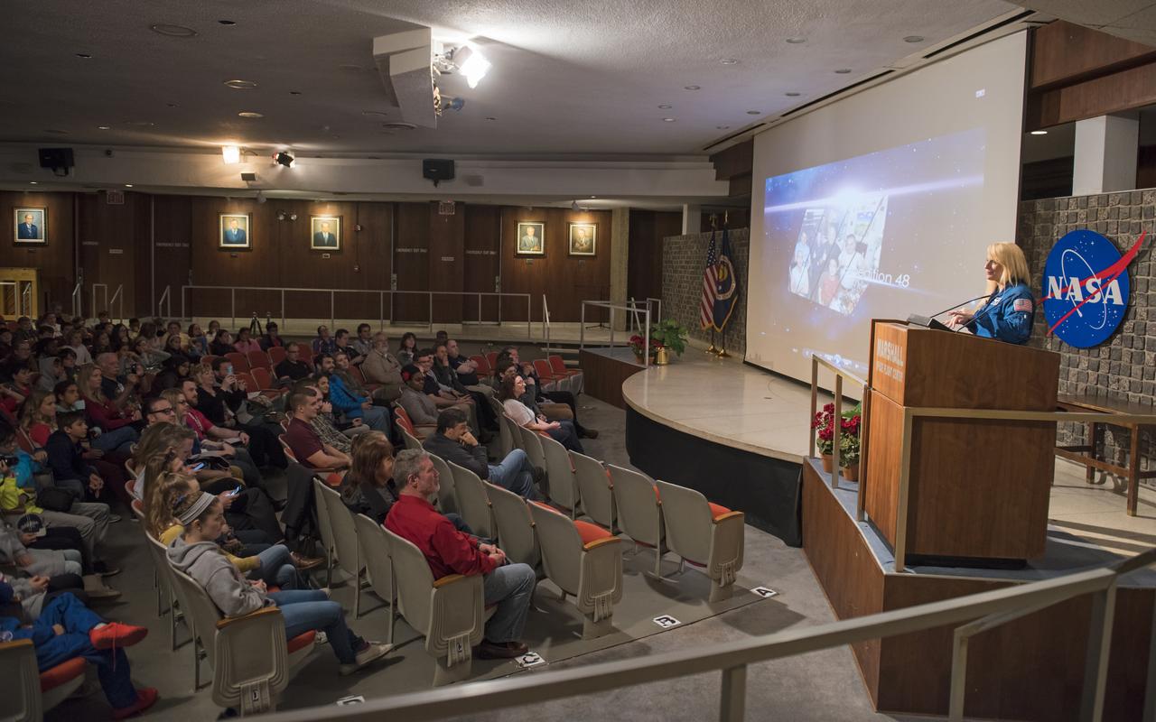
NASA astronaut Kate Rubins presents highlights from Expedition 48/49, her mission to the International Space Station, to team members and Space Camp students from the U.S. Space & Rocket Center in Huntsville, April 6 at NASA's Marshall Space Flight Center. During her mission, Rubins became the first person to sequence DNA in space, researching technology development for deep-space exploration by humans, Earth and space science. She also conducted two spacewalks, in which she and NASA astronaut Jeff Williams installed an International Docking Adapter and performed maintenance of the station's external thermal control system and installed high-definition cameras.
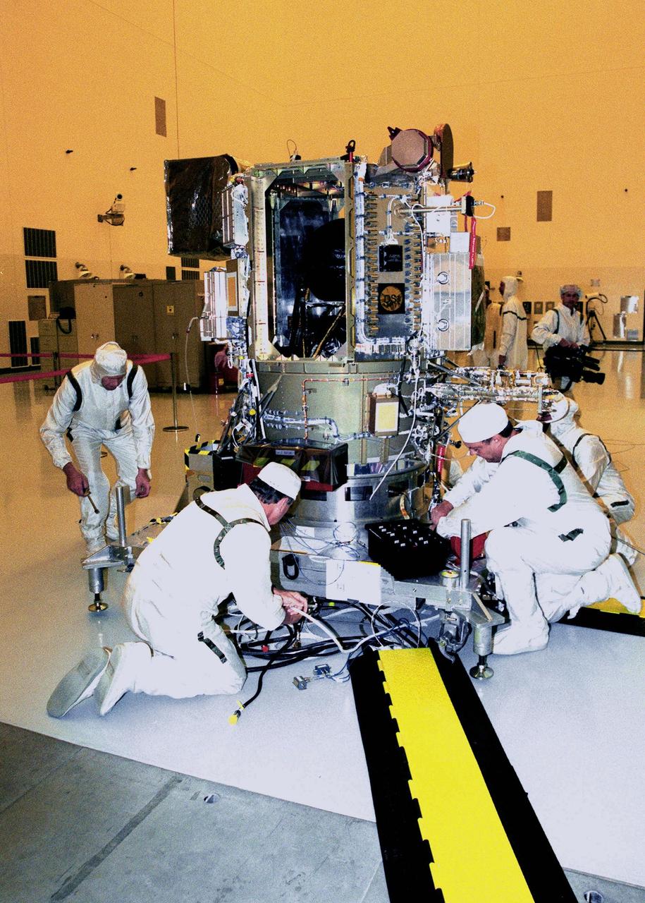
KENNEDY SPACE CENTER, FLA. -- Workers in the Payload Hazardous Servicing Facility check equipment on Deep Space 1 to prepare it for launch aboard a Boeing Delta 7326 rocket in October. The first flight in NASA's New Millennium Program, Deep Space 1 is designed to validate 12 new technologies for scientific space missions of the next century. Onboard experiments include an ion propulsion engine and software that tracks celestial bodies so the spacecraft can make its own navigation decisions without the intervention of ground controllers. Most of its mission objectives will be completed within the first two months. A near-Earth asteroid, 1992 KD, has also been selected for a possible flyby
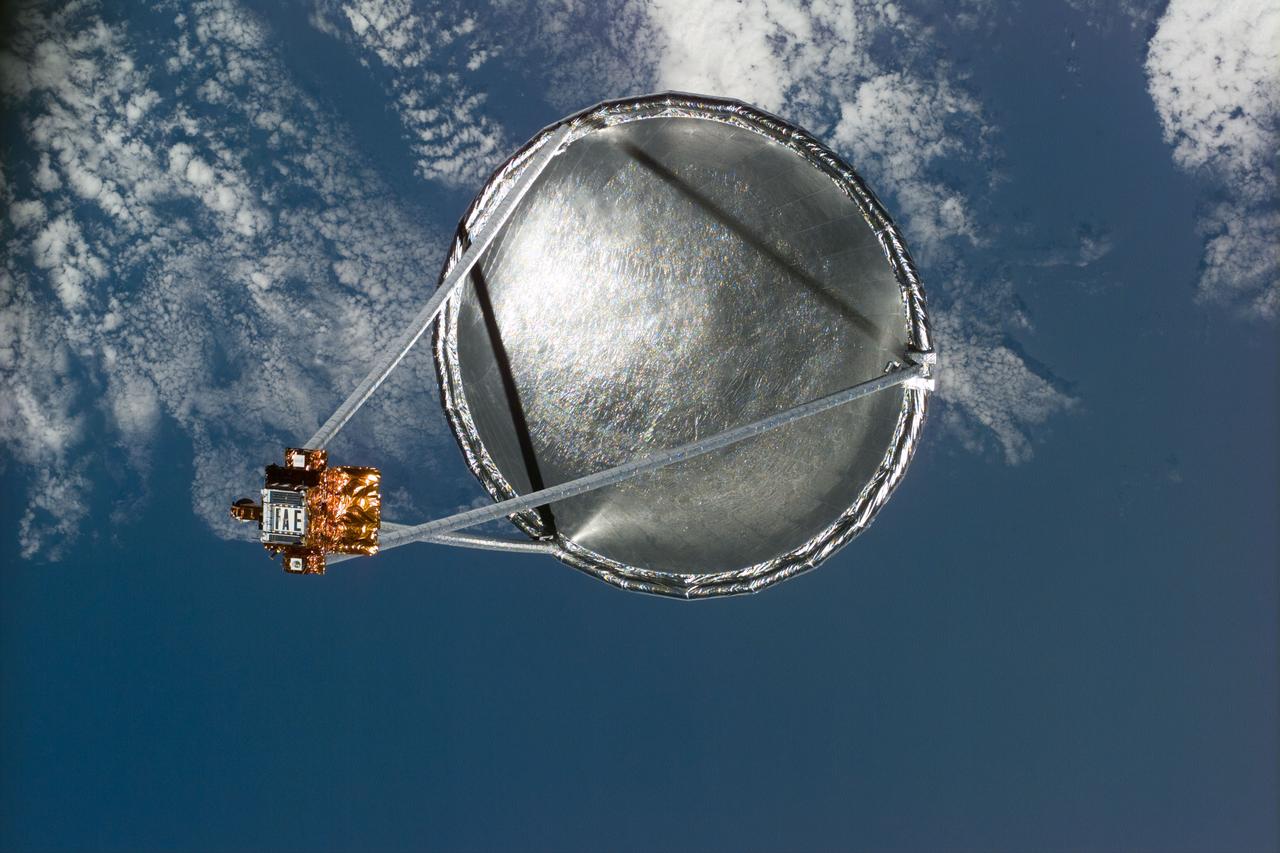
S77-E-5022 (20 May 1996)--- Following its deployment from the Space Shuttle Endeavour, the Spartan 207/Inflatable Antenna Experiment (IAE) payload is backdropped over clouds and water. The view was photographed with an Electronic Still Camera (ESC) and downlinked to flight controllers on the first full day of orbital operations by the six-member crew. Managed by Goddard Space Flight Center (GSFC), Spartan is designed to provide short-duration, free-flight opportunities for a variety of scientific studies. The Spartan configuration on this flight is unique in that the IAE is part of an additional separate unit which is ejected once the experiment is completed. The IAE experiment will lay the groundwork for future technology development in inflatable space structures, which will be launched and then inflated like a balloon on-orbit.
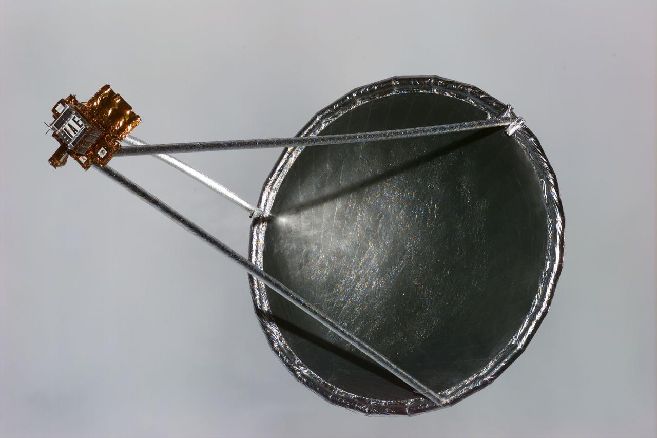
S77-E-5033 (20 May 1996) --- Following its deployment from the Space Shuttle Endeavour, the Spartan 207/Inflatable Antenna Experiment (IAE) payload is backdropped against a wall of grayish clouds. The view was photographed with an Electronic Still Camera (ESC) and downlinked to flight controllers on the first full day of orbital operations by the six-member crew. Managed by Goddard Space Flight Center (GSFC), Spartan is designed to provide short-duration, free-flight opportunities for a variety of scientific studies. The Spartan configuration on this flight is unique in that the IAE is part of an additional separate unit which is ejected once the experiment is completed. The IAE experiment will lay the groundwork for future technology development in inflatable space structures, which will be launched and then inflated like a balloon on-orbit.
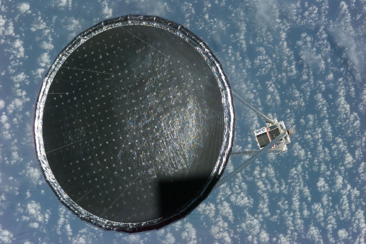
S77-E-5027 (20 May 1996)--- Following its deployment from the Space Shuttle Endeavour, the Spartan 207/Inflatable Antenna Experiment (IAE) payload is backdropped over clouds and water. The view was photographed with an Electronic Still Camera (ESC) and downlinked to flight controllers on the first full day of orbital operations by the six-member crew. Managed by Goddard Space Flight Center (GSFC), Spartan is designed to provide short-duration, free-flight opportunities for a variety of scientific studies. The Spartan configuration on this flight is unique in that the IAE is part of an additional separate unit which is ejected once the experiment is completed. The IAE experiment will lay the groundwork for future technology development in inflatable space structures, which will be launched and then inflated like a balloon on-orbit.
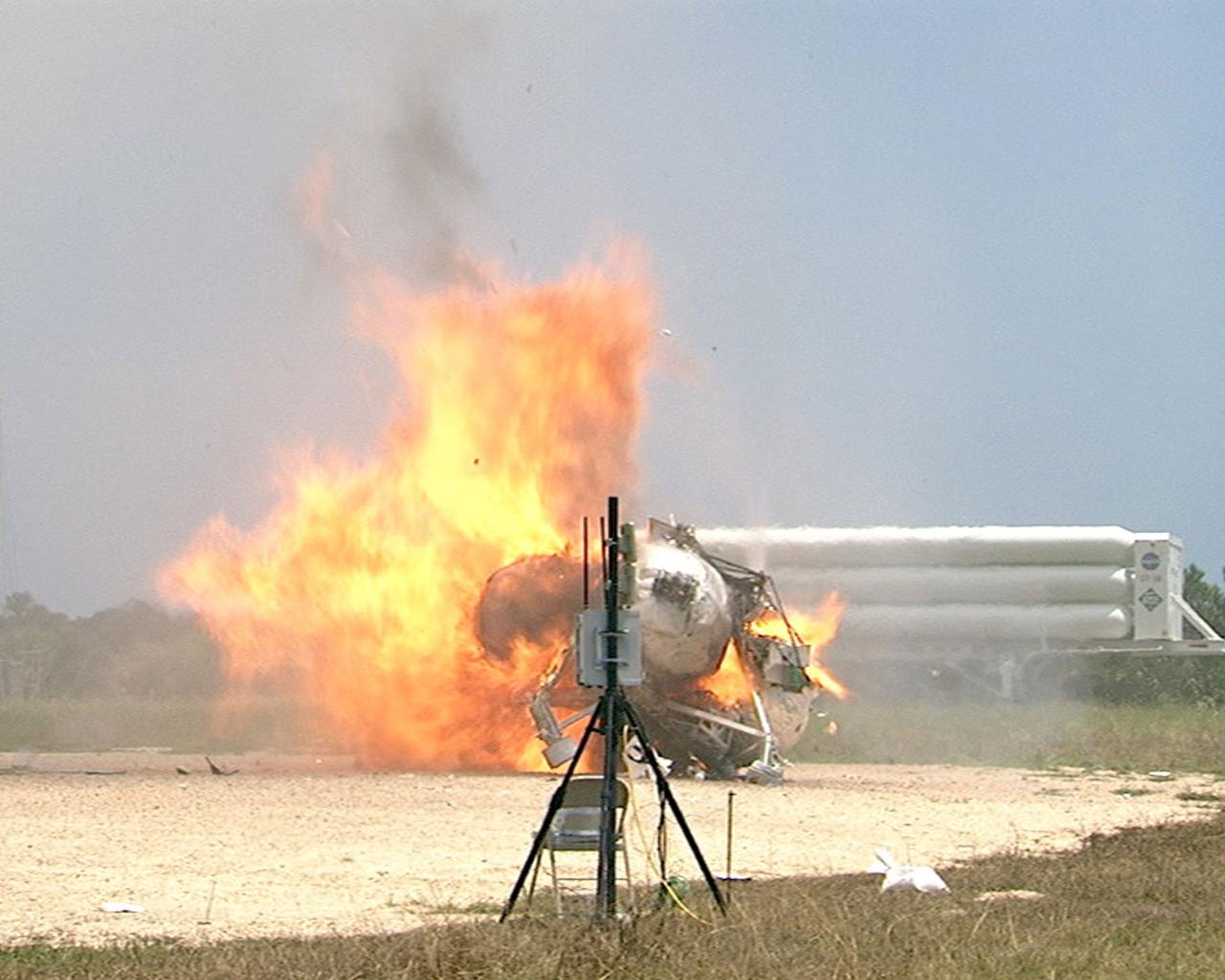
CAPE CANAVERAL, Fla. – During a free-flight test of the Project Morpheus vehicle at the Shuttle Landing Facility at NASA’s Kennedy Space Center in Florida, the vehicle lifted off the ground and then experienced a hardware component failure, which prevented it from maintaining stable flight. Engineers are looking into the test data and the agency will release information as it becomes available. Failures such as these were anticipated prior to the test, and are part of the development process for any complex spaceflight hardware. Testing of the prototype lander had been ongoing at NASA’s Johnson Space Center in Houston in preparation for its first free-flight test at Kennedy Space Center. Morpheus was manufactured and assembled at JSC and Armadillo Aerospace. Morpheus is large enough to carry 1,100 pounds of cargo to the moon – for example, a humanoid robot, a small rover, or a small laboratory to convert moon dust into oxygen. The primary focus of the test is to demonstrate an integrated propulsion and guidance, navigation and control system that can fly a lunar descent profile to exercise the Autonomous Landing and Hazard Avoidance Technology, or ALHAT, safe landing sensors and closed-loop flight control. For more information on Project Morpheus, visit http://morpheuslander.jsc.nasa.gov/. Photo credit: NASA
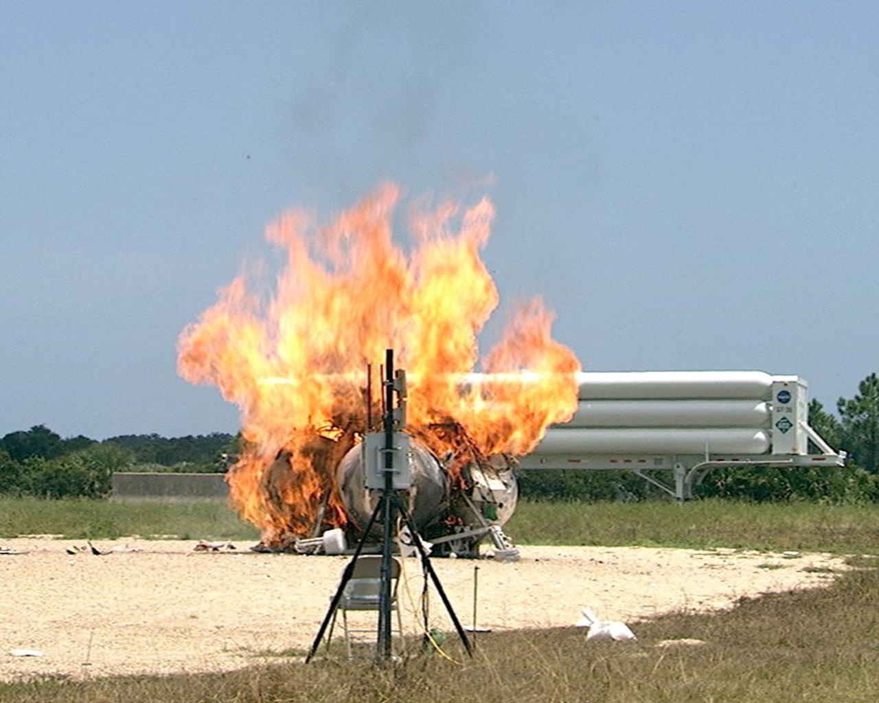
CAPE CANAVERAL, Fla. – During a free-flight test of the Project Morpheus vehicle at the Shuttle Landing Facility at NASA’s Kennedy Space Center in Florida, the vehicle lifted off the ground and then experienced a hardware component failure, which prevented it from maintaining stable flight. No one was injured and the resulting fire was extinguished by Kennedy fire personnel. Engineers are looking into the test data and the agency will release information as it becomes available. Failures such as these were anticipated prior to the test, and are part of the development process for any complex spaceflight hardware. Testing of the prototype lander had been ongoing at NASA’s Johnson Space Center in Houston in preparation for its first free-flight test at Kennedy Space Center. Morpheus was manufactured and assembled at JSC and Armadillo Aerospace. Morpheus is large enough to carry 1,100 pounds of cargo to the moon – for example, a humanoid robot, a small rover, or a small laboratory to convert moon dust into oxygen. The primary focus of the test is to demonstrate an integrated propulsion and guidance, navigation and control system that can fly a lunar descent profile to exercise the Autonomous Landing and Hazard Avoidance Technology, or ALHAT, safe landing sensors and closed-loop flight control. For more information on Project Morpheus, visit http://morpheuslander.jsc.nasa.gov/. Photo credit: NASA
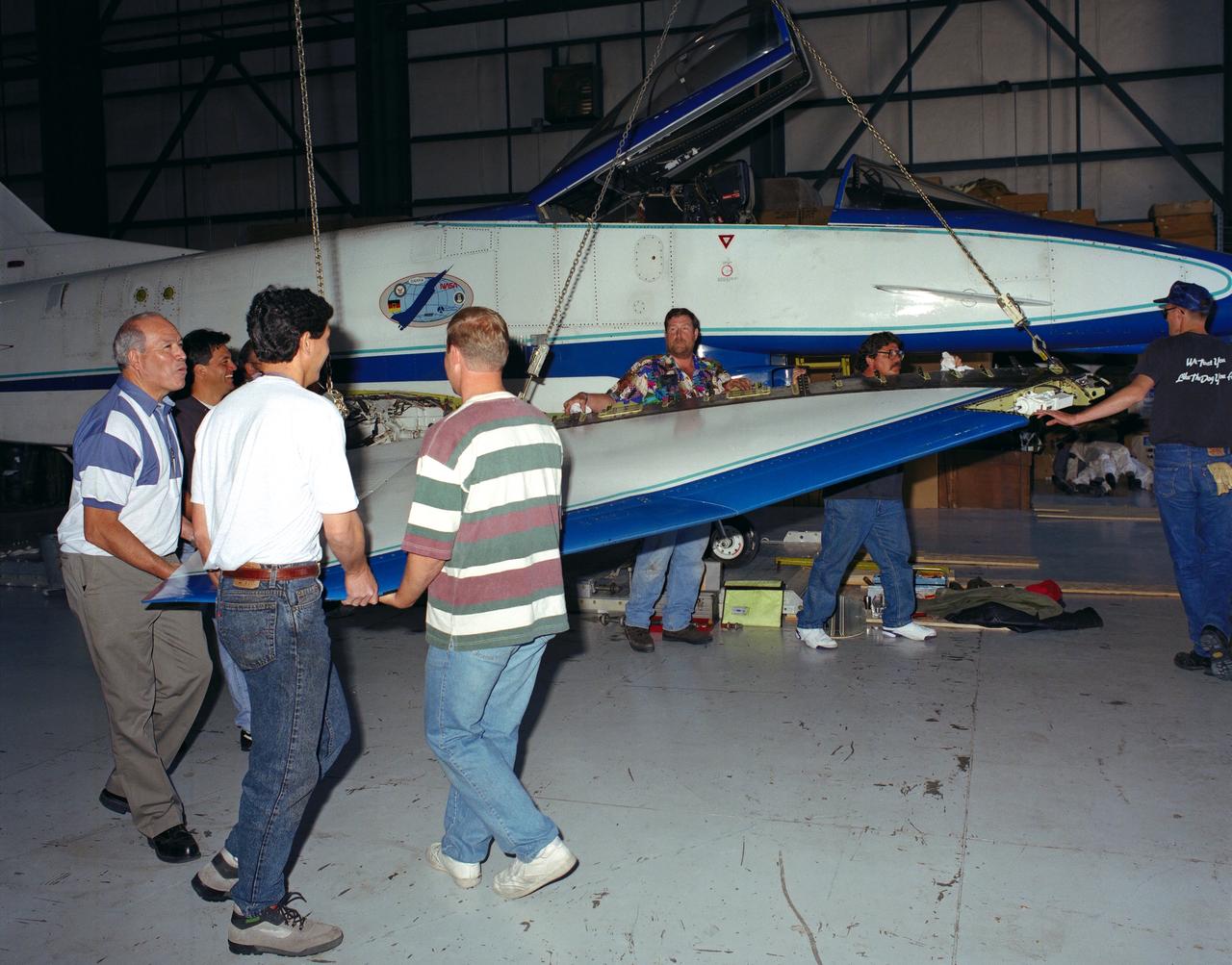
U.S. and German personnel of the X-31 Enhanced Fighter Maneuverability Technology Demonstrator aircraft program removing the right wing of the aircraft, which was ferried from Edwards Air Force Base, California, to Europe on May 22, 1995 aboard an Air Force Reserve C-5 transport. The X-31, based at the NASA Dryden Flight Research Center was ferried to Europe and flown in the Paris Air Show in June. The wing of the X-31 was removed on May 18, 1995, to allow the aircraft to fit inside the C-5 fuselage. Officials of the X-31 project used Manching, Germany, as a staging base to prepare the aircraft for the flight demonstration. At the air show, the X-31 demonstrated the value of using thrust vectoring (directing engine exhaust flow) coupled with advanced flight control systems to provide controlled flight at very high angles of attack. The aircraft arrived back at Edwards in a Air Force Reserve C-5 on June 25, 1995 and off loaded at Dryden June 27. The X-31 aircraft was developed jointly by Rockwell International's North American Aircraft Division (now part of Boeing) and Daimler-Benz Aerospace (formerly Messerschmitt-Bolkow-Blohm), under sponsorship by the U.S. Department of Defense and the German Federal Ministry of Defense.
CAPE CANAVERAL, Fla. – During a free-flight test of the Project Morpheus vehicle at the Shuttle Landing Facility at NASA’s Kennedy Space Center in Florida, the vehicle lifted off the ground and then experienced a hardware component failure, which prevented it from maintaining stable flight. No one was injured and the resulting fire was extinguished by Kennedy fire personnel. Engineers are looking into the test data and the agency will release information as it becomes available. Failures such as these were anticipated prior to the test, and are part of the development process for any complex spaceflight hardware. Testing of the prototype lander had been ongoing at NASA’s Johnson Space Center in Houston in preparation for its first free-flight test at Kennedy Space Center. Morpheus was manufactured and assembled at JSC and Armadillo Aerospace. Morpheus is large enough to carry 1,100 pounds of cargo to the moon – for example, a humanoid robot, a small rover, or a small laboratory to convert moon dust into oxygen. The primary focus of the test is to demonstrate an integrated propulsion and guidance, navigation and control system that can fly a lunar descent profile to exercise the Autonomous Landing and Hazard Avoidance Technology, or ALHAT, safe landing sensors and closed-loop flight control. For more information on Project Morpheus, visit http://morpheuslander.jsc.nasa.gov/. Photo credit: NASA
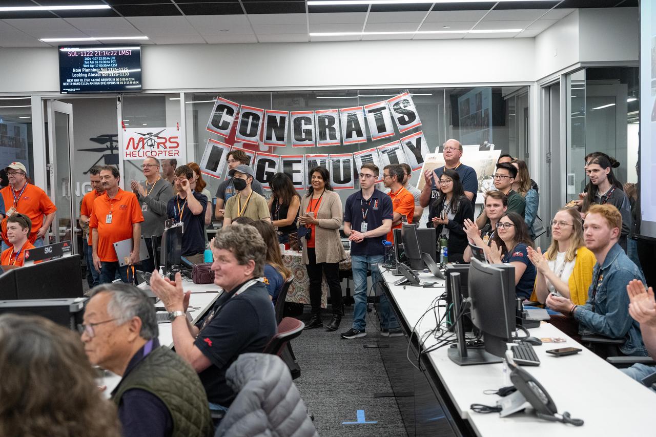
Engineers working on NASA's Ingenuity Mars Helicopter gathered together in a control room for one last time to monitor a transmission from the history-making helicopter at the agency's Jet Propulsion Laboratory on April 16, 2024. The transmission confirmed the operation of a software patch that will allow Ingenuity to act as a stationary testbed and collect data that could benefit future explorers of the Red Planet. Originally designed as short-lived technology demonstration mission that would perform up to five experimental test flights over 30 days, the first aircraft on another world operated from the Martian surface for almost three years, flew more than 14 times farther than planned, and logged more than two hours of total flight time. Its 72nd and final flight was Jan. 18, 2024. https://photojournal.jpl.nasa.gov/catalog/PIA26318

NASA's Ingenuity Mars Helicopter took this shot, capturing its own shadow, while hovering over the Martian surface on April 19, 2021, during the first instance of powered, controlled flight on another planet. It used its navigation camera, which autonomously tracks the ground during flight. The Ingenuity Mars Helicopter was built by JPL, which also manages this technology demonstration project for NASA Headquarters. It is supported by NASA's Science Mission Directorate, Aeronautics Research Mission Directorate, and Space Technology Mission Directorate. NASA's Ames Research Center and Langley Research Center provided significant flight performance analysis and technical assistance during Ingenuity's development. A key objective for Perseverance's mission on Mars is astrobiology, including the search for signs of ancient microbial life. The rover will characterize the planet's geology and past climate, pave the way for human exploration of the Red Planet, and be the first mission to collect and cache Martian rock and regolith (broken rock and dust). Subsequent NASA missions, in cooperation with ESA (European Space Agency), would send spacecraft to Mars to collect these sealed samples from the surface and return them to Earth for in-depth analysis. The Mars 2020 Perseverance mission is part of NASA's Moon to Mars exploration approach, which includes Artemis missions to the Moon that will help prepare for human exploration of the Red Planet. https://photojournal.jpl.nasa.gov/catalog/PIA24584
The test of twin Linear Aerospike XRS-2200 engines, originally built for the X-33 program, was performed on August 6, 2001 at NASA's Sternis Space Center, Mississippi. The engines were fired for the planned 90 seconds and reached a planned maximum power of 85 percent. NASA's Second Generation Reusable Launch Vehicle Program , also known as the Space Launch Initiative (SLI), is making advances in propulsion technology with this third and final successful engine hot fire, designed to test electro-mechanical actuators. Information learned from this hot fire test series about new electro-mechanical actuator technology, which controls the flow of propellants in rocket engines, could provide key advancements for the propulsion systems for future spacecraft. The Second Generation Reusable Launch Vehicle Program, led by NASA's Marshall Space Flight Center in Huntsville, Alabama, is a technology development program designed to increase safety and reliability while reducing costs for space travel. The X-33 program was cancelled in March 2001.
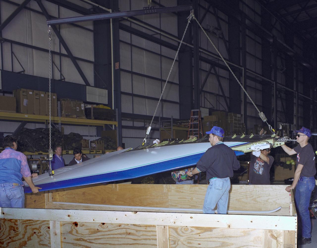
The right wing of the X-31 Enhanced Fighter Maneuverability Technology Demonstrator Aircraft is seen here being put into a shipping container May 18, 1995, at NASA's Dryden Flight Research Center, Edwards, California, by U.S. and German members of the program. To fit inside an Air Force Reserve C-5 transport, which was used to ferry the X-31 to Europe on May 22, 1995, the right wing had to be removed. Manching, Germany, was used as a staging base to prepare the aircraft for participation in the Paris Air Show. At the air show on June 11 through the 18th, the X-31 demonstrated the value of using thrust vectoring (directing engine exhaust flow) coupled with advanced flight control systems to provide controlled flight at very high angles of attack. The aircraft arrived back at Edwards in an Air Force Reserve C-5 on June 25, 1995, and off loaded at Dryden the 27th. The X-31 aircraft was developed jointly by Rockwell International's North American Aircraft Division (now part of Boeing) and Daimler-Benz Aerospace (formerly Messerschmitt-Bolkow-Blohm), under sponsorship by the U.S. Department of Defense and the German Federal Ministry of Defense.