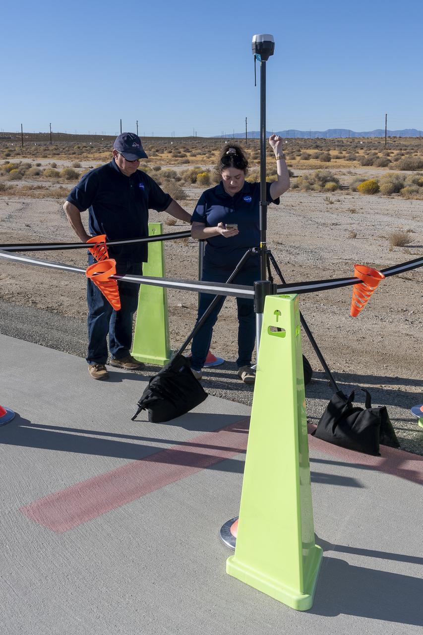
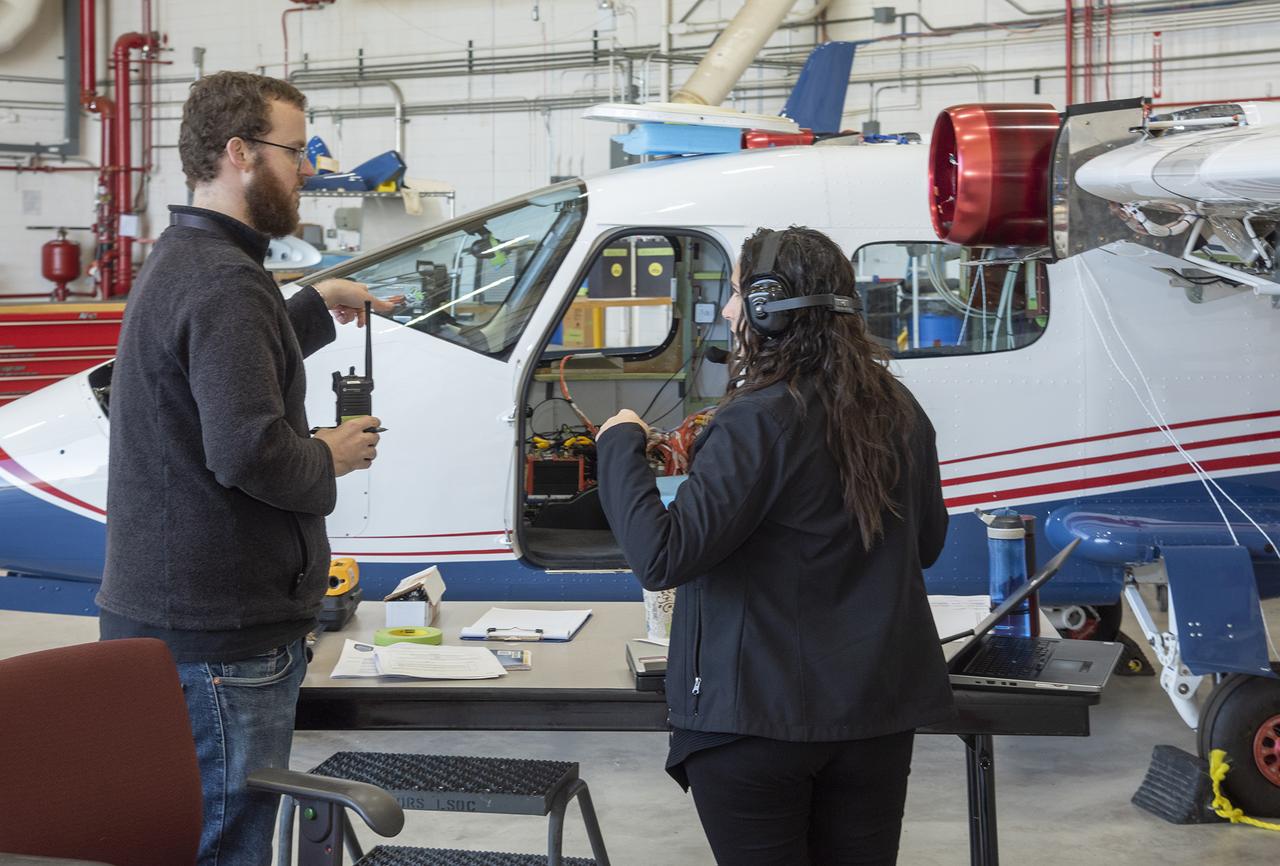
NASA Pathways intern Saré Culbertson, right, works with NASA operations engineer Jack Hayes at NASA’s Armstrong Flight Research Center in Edwards, California, on Nov. 7, 2024. They are verifying GPS and global navigation satellite system coordinates using Emlid Reach RS2+ receiver equipment, which supports surveying, mapping, and navigation in preparation for future air taxi test flight research.
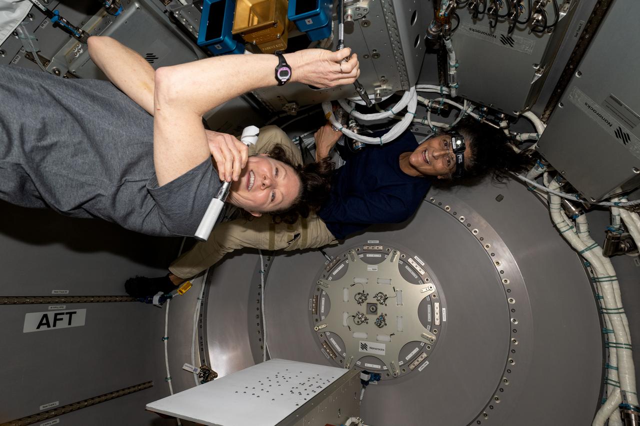
iss071e403704 (July 24, 2024) --- NASA astronauts (from left) Tracy C. Dyson, Expedition 71 Flight Engineer, and Suni Williams, Pilot for Boeing's Crew Flight Test, work inside the NanoRacks Bishop airlock located in the port side of the International Space Station's Tranquility module. The duo installed the the ArgUS Mission-1 technology demonstration hardware inside Bishop for placement outside in the vacuum of space to test the external operations of communications, computer processing, and high-definition video gear.
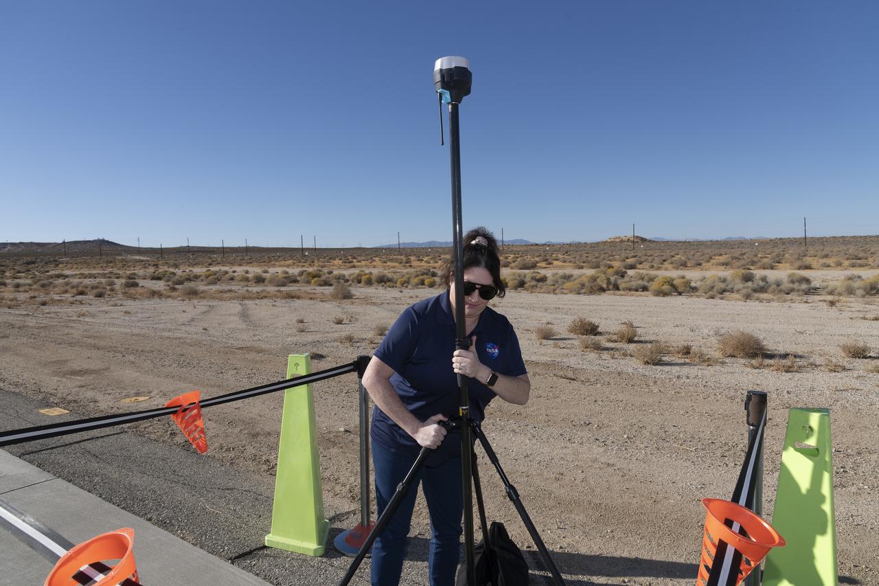
Saré Culbertson, NASA Pathways intern at NASA’s Armstrong Flight Research Center in Edwards, California, adjusts the Emlid Reach RS2+ receiver equipment that connects with GPS and global navigation satellite systems on Nov. 7, 2024, in preparation for future air taxi test flight research.
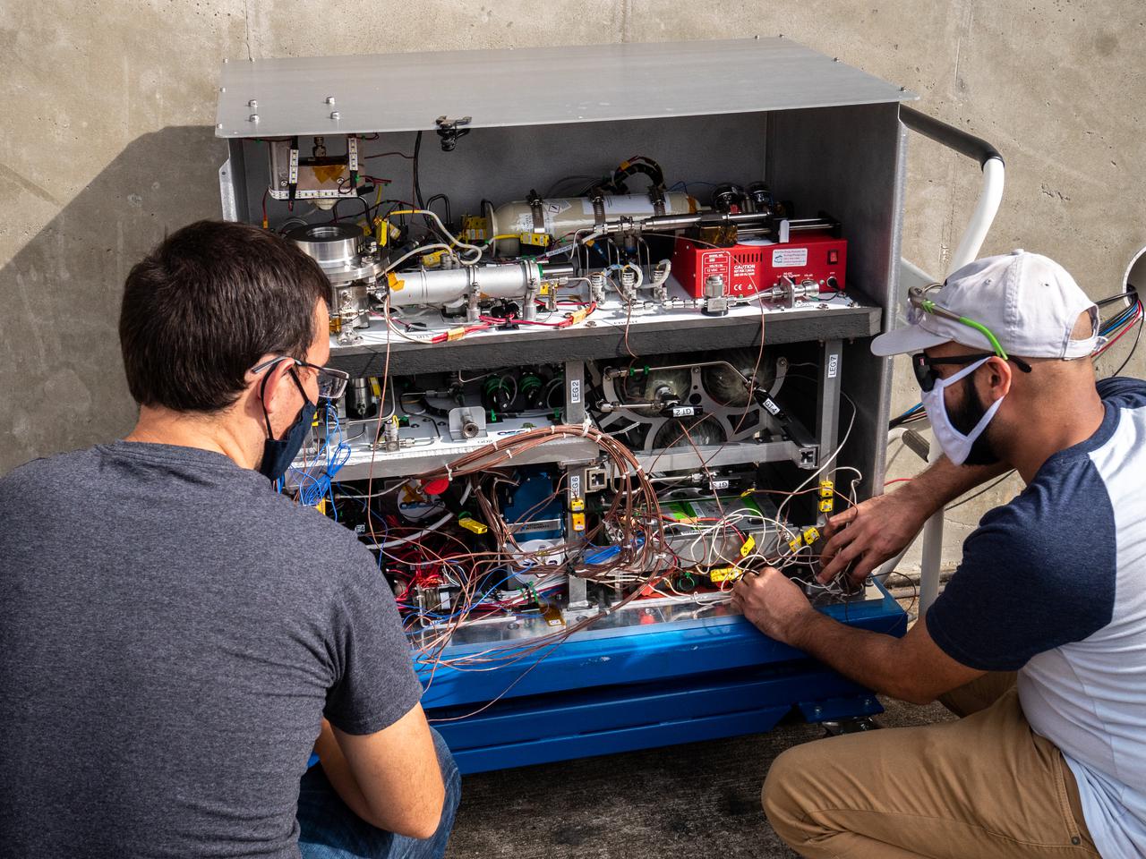
Chemical Engineer David Rinderknecht, left, and Thermal/Fluid Analysis Engineer Malay Shah prepare the Orbital Syngas Commodity Augmentation Reactor (OSCAR) for thermal testing Jan. 26, 2021, at NASA’s Kennedy Space Center in Florida. The tests are in preparation for a scheduled suborbital flight test later this year facilitated by NASA’s Flight Opportunities program. The testing ensures the thermal environment of the payload won’t create additional hazards during flight and that OSCAR can successfully operate within the temperature range it may encounter as it performs tests in microgravity.
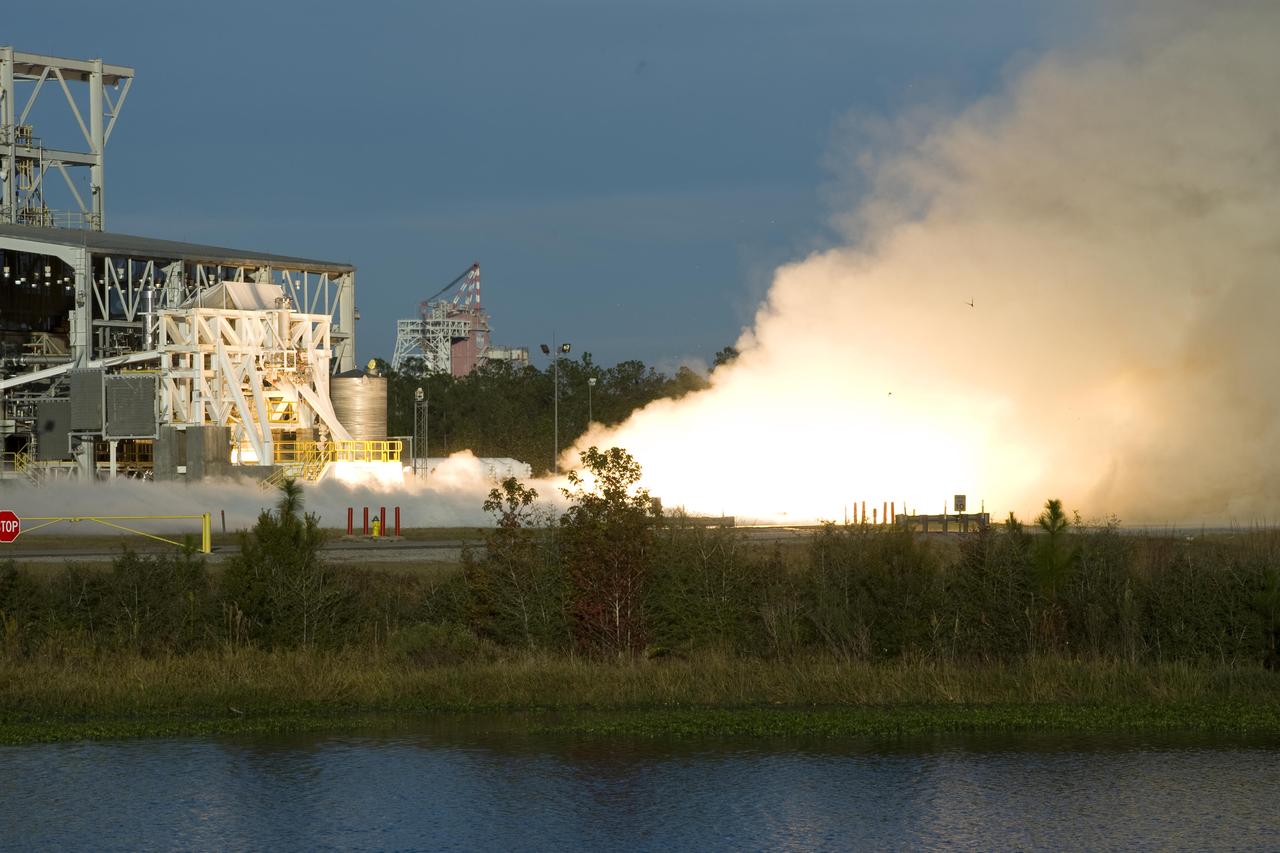
Fire and steam signal a successful test firing of Orbital Sciences Corporation's Aerojet AJ26 rocket engine at John C. Stennis Space Center. AJ26 engines will be used to power Orbital's Taurus II space vehicle on commercial cargo flights to the International Space Station. On Nov. 10, operators at Stennis' E-1 Test Stand conducted a 10-second test fire of the engine, the first of a series of three verification tests. Orbital has partnered with NASA to provide eight missions to the ISS by 2015.

Test of Unmanned Aircraft Systems Traffic Management (UTM) technical capability Level 2 (TCL2) at Reno-Stead Airport, Nevada. During the test, five drones simultaneously crossed paths, separated by altitude. Two drones flew beyond visual line-of-sight and three flew within line-of-sight of their operators. Engineers Priya Venkatesan and Joey Mercer review flight paths using the UAS traffic management research platform at flight operations mission control at NASA’s UTM TCL2 test.
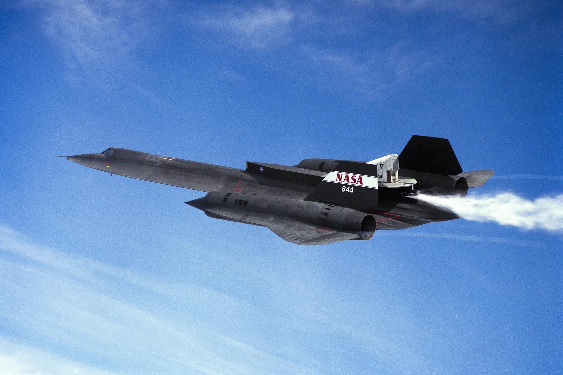
The NASA SR-71 triple-supersonic aircraft carries the Linear Aerospike Experiment on Wednesday, March 4, 1998, during a flight from NASA’s Armstrong (then Dryden) Flight Research Center in Edwards, California. Gaseous helium and liquid nitrogen cycled through the linear aerospike engine during the flight to check the engine’s plumbing system for leaks and to check the engine operating characteristics. Cold-flow tests must be accomplished successfully before firing the rocket engine experiment in flight.

A Wright Aeronautical XRJ47-W-5 ramjet installed in a test chamber of the National Advisory Committee for Aeronautics’ (NACA) new Propulsion Systems Laboratory at the Lewis Flight Propulsion Laboratory. Construction of the facility had only recently been completed, and NACA engineers were still testing the various operating systems. The Propulsion Systems Laboratory was the NACA’s most powerful facility for testing full-scale engines in simulated flight altitudes. It contained two 14-foot diameter and 100-foot-long altitude chambers that ran parallel to one another with a control room in between. The engine being tested was installed inside the test section of one of the chambers, seen in this photograph. Extensive instrumentation was fitted onto the engine prior to the test. Once the chamber was sealed, the altitude conditions were introduced, and the engine was ignited. Operators in the control room could run the engine at the various speeds and adjust the altitude conditions to the desired levels. The engine’s exhaust was ejected into the cooling equipment. Two 48-inch diameter XRJ47-W-5 ramjets were used to power the North American Aviation Navaho Missile. The Navaho was a winged missile that was intended to travel up to 3000 miles carrying a nuclear warhead. It was launched using rocket booster engines that were ejected after the missile’s ramjet engines were ignited.
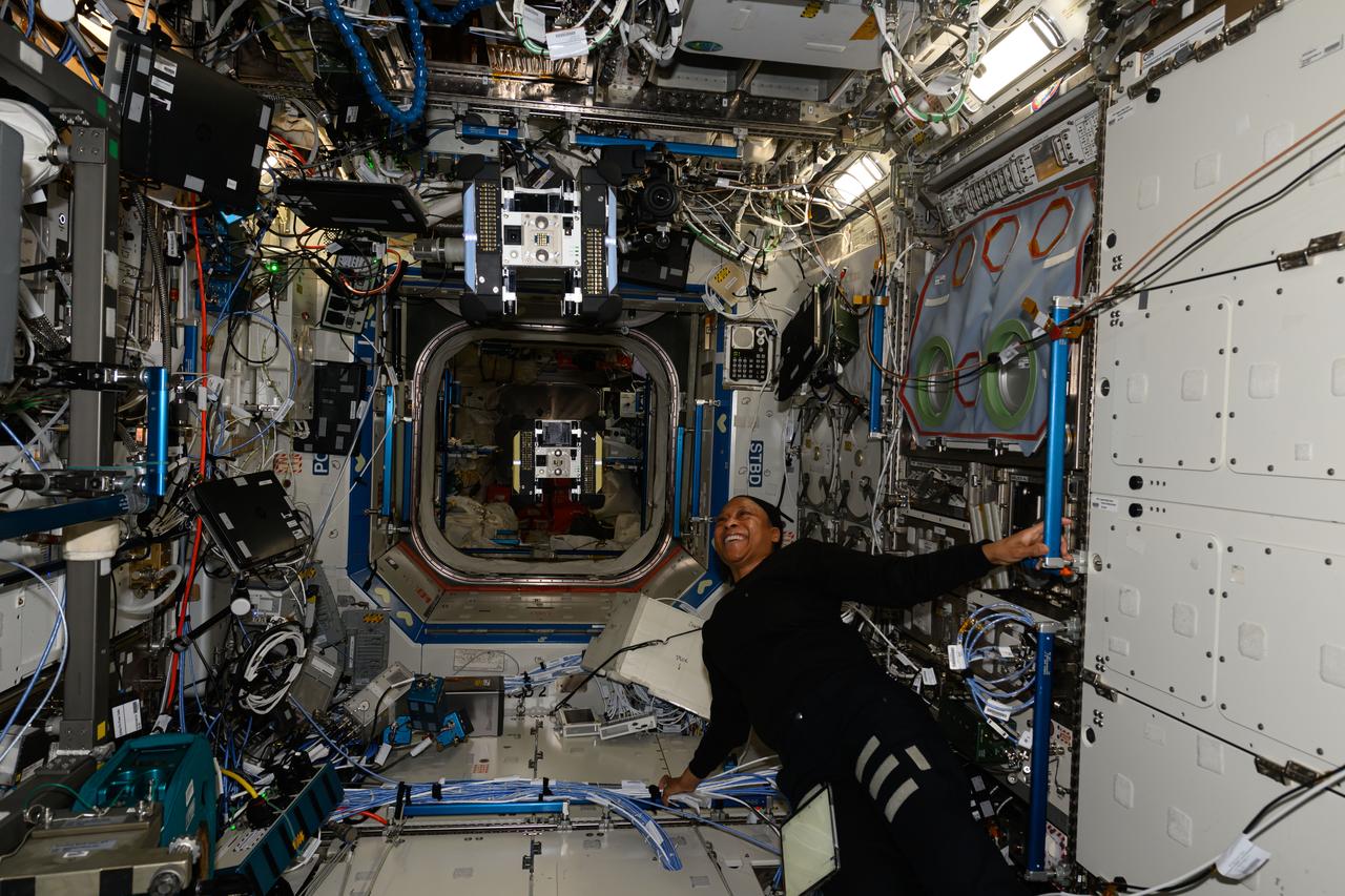
iss071e154431 (May 31, 2024) --- Expedition 71 Flight Engineer and NASA astronaut Jeanette Epps observes an Astrobee robotic free flyer during an operations test inside the International Space Station's Kibo laboratory module.
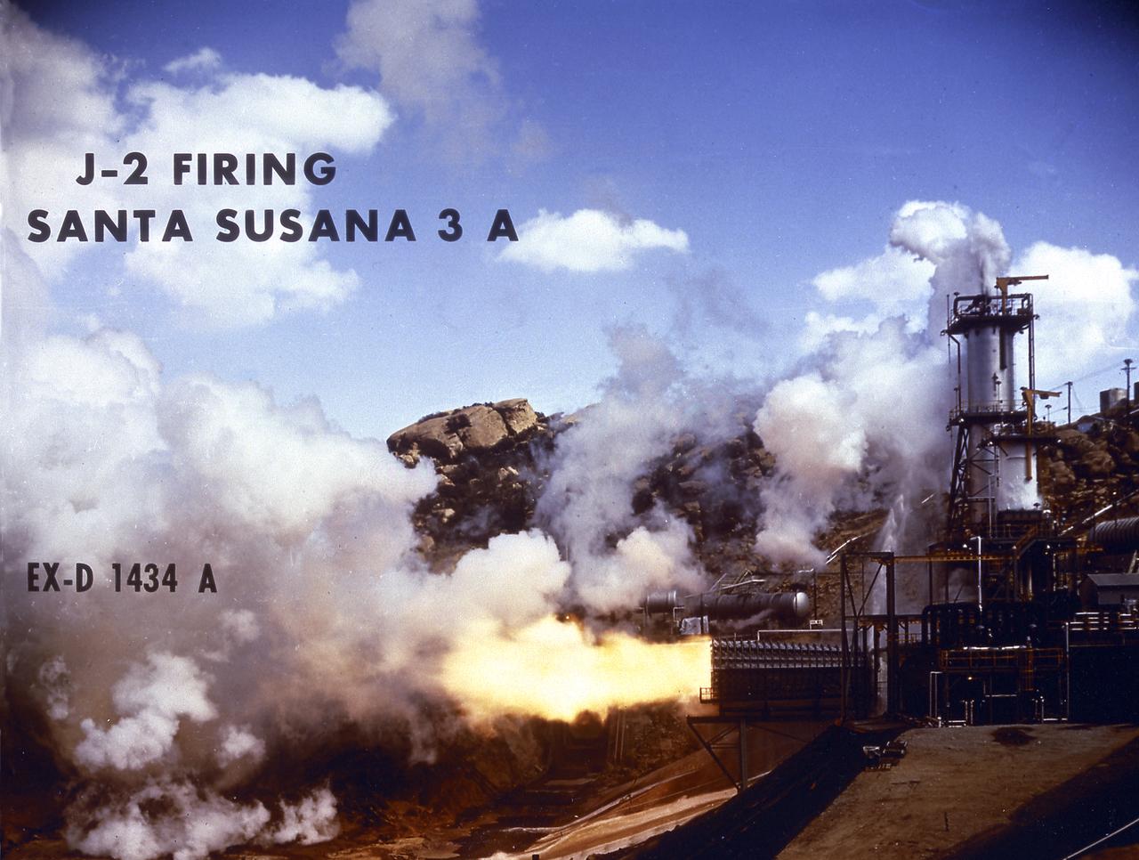
Smokeless flame juts from the diffuser of a unique vacuum chamber in which the upper stage rocket engine, the hydrogen fueled J-2, was tested at a simulated space altitude in excess of 60,000 feet. The smoke you see is actually steam. In operation, vacuum is established by injecting steam into the chamber and is maintained by the thrust of the engine firing through the diffuser. The engine was tested in this environment for start, stop, coast, restart, and full-duration operations. The chamber was located at Rocketdyne's Propulsion Field Laboratory, in the Santa Susana Mountains, near Canoga Park, California. The J-2 engine was developed by Rocketdyne for the Marshall Space Flight Center.
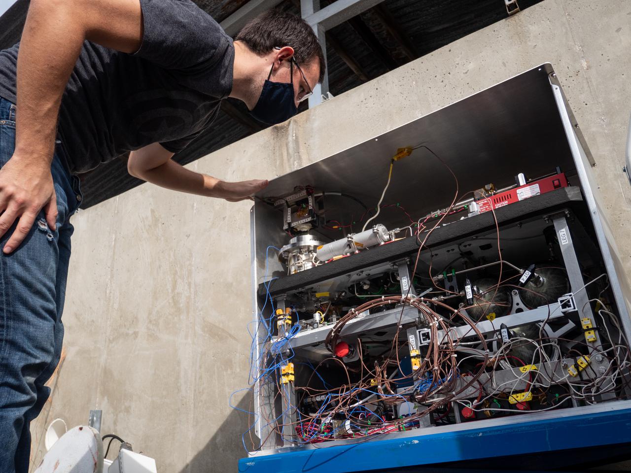
Chemical Engineer David Rinderknecht prepares the Orbital Syngas Commodity Augmentation Reactor (OSCAR) for thermal testing Jan. 26, 2021, at NASA’s Kennedy Space Center in Florida. The tests are in preparation for a scheduled suborbital flight test later this year facilitated by NASA’s Flight Opportunities program. The testing ensures the thermal environment of the payload won’t create additional hazards during flight and that OSCAR can successfully operate within the temperature range it may encounter as it performs tests in microgravity.
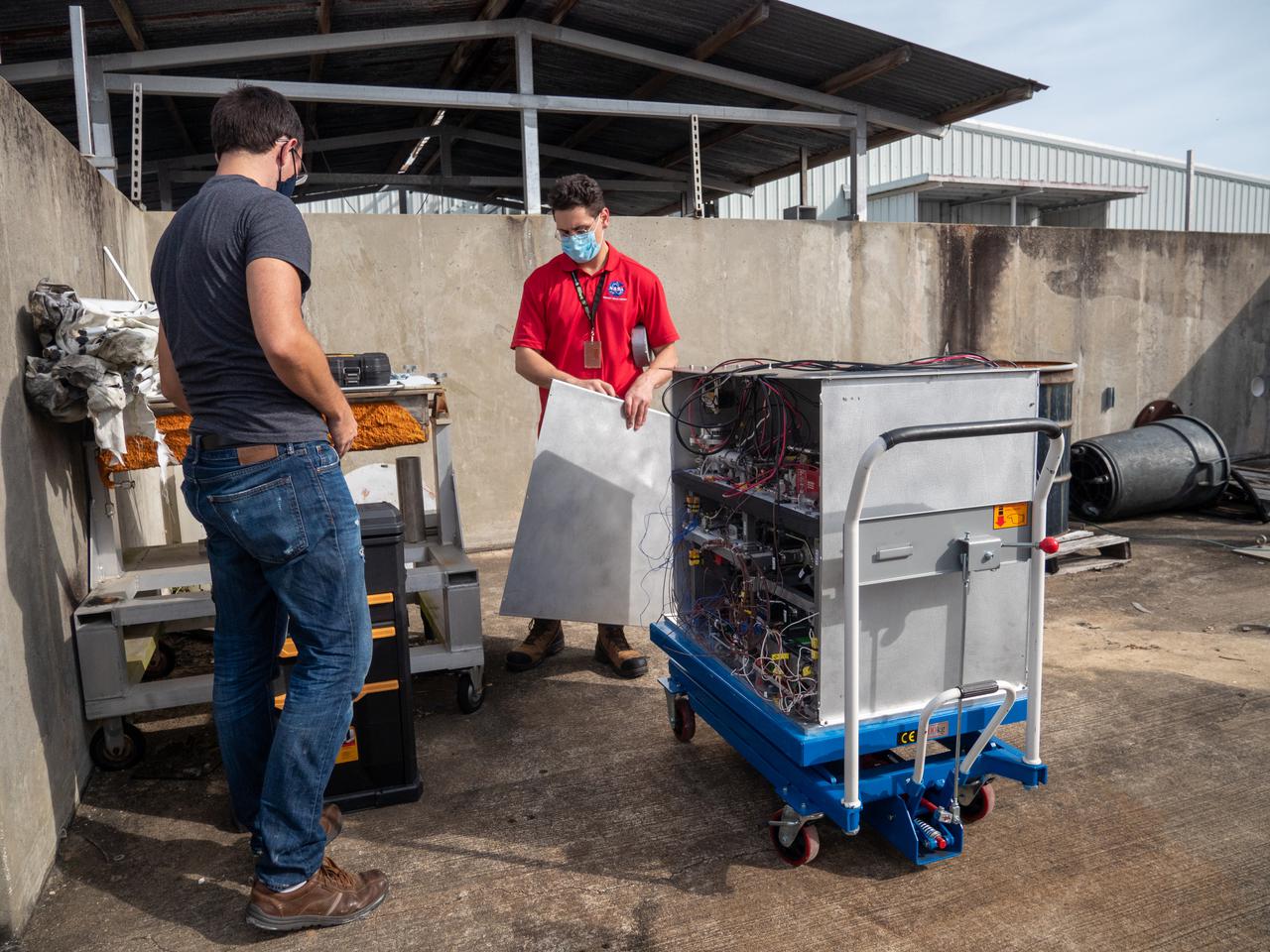
Chemical Engineer David Rinderknecht, left, and Ray Pitts, co-principal investigator for the Orbital Syngas Commodity Augmentation Reactor (OSCAR), prepare OSCAR for thermal testing Jan. 26, 2021, at NASA’s Kennedy Space Center in Florida. The tests are in preparation for a scheduled suborbital flight test later this year facilitated by NASA’s Flight Opportunities program. The testing ensures the thermal environment of the payload won’t create additional hazards during flight and that OSCAR can successfully operate within the temperature range it may encounter as it performs tests in microgravity.
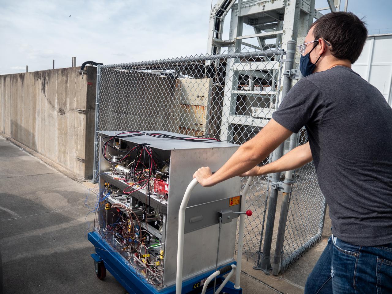
Chemical Engineer David Rinderknecht prepares the Orbital Syngas Commodity Augmentation Reactor (OSCAR) for thermal testing Jan. 26, 2021, at NASA’s Kennedy Space Center in Florida. The tests are in preparation for a scheduled suborbital flight test later this year facilitated by NASA’s Flight Opportunities program. The testing ensures the thermal environment of the payload won’t create additional hazards during flight and that OSCAR can successfully operate within the temperature range it may encounter as it performs tests in microgravity.
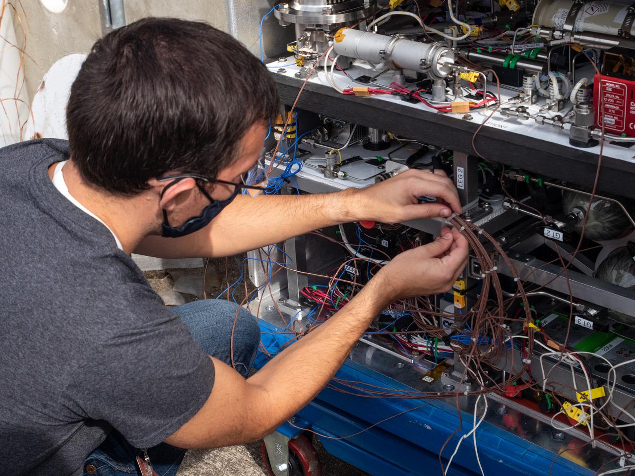
Chemical Engineer David Rinderknecht prepares the Orbital Syngas Commodity Augmentation Reactor (OSCAR) for thermal testing Jan. 26, 2021, at NASA’s Kennedy Space Center in Florida. The tests are in preparation for a scheduled suborbital flight test later this year facilitated by NASA’s Flight Opportunities program. The testing ensures the thermal environment of the payload won’t create additional hazards during flight and that OSCAR can successfully operate within the temperature range it may encounter as it performs tests in microgravity.
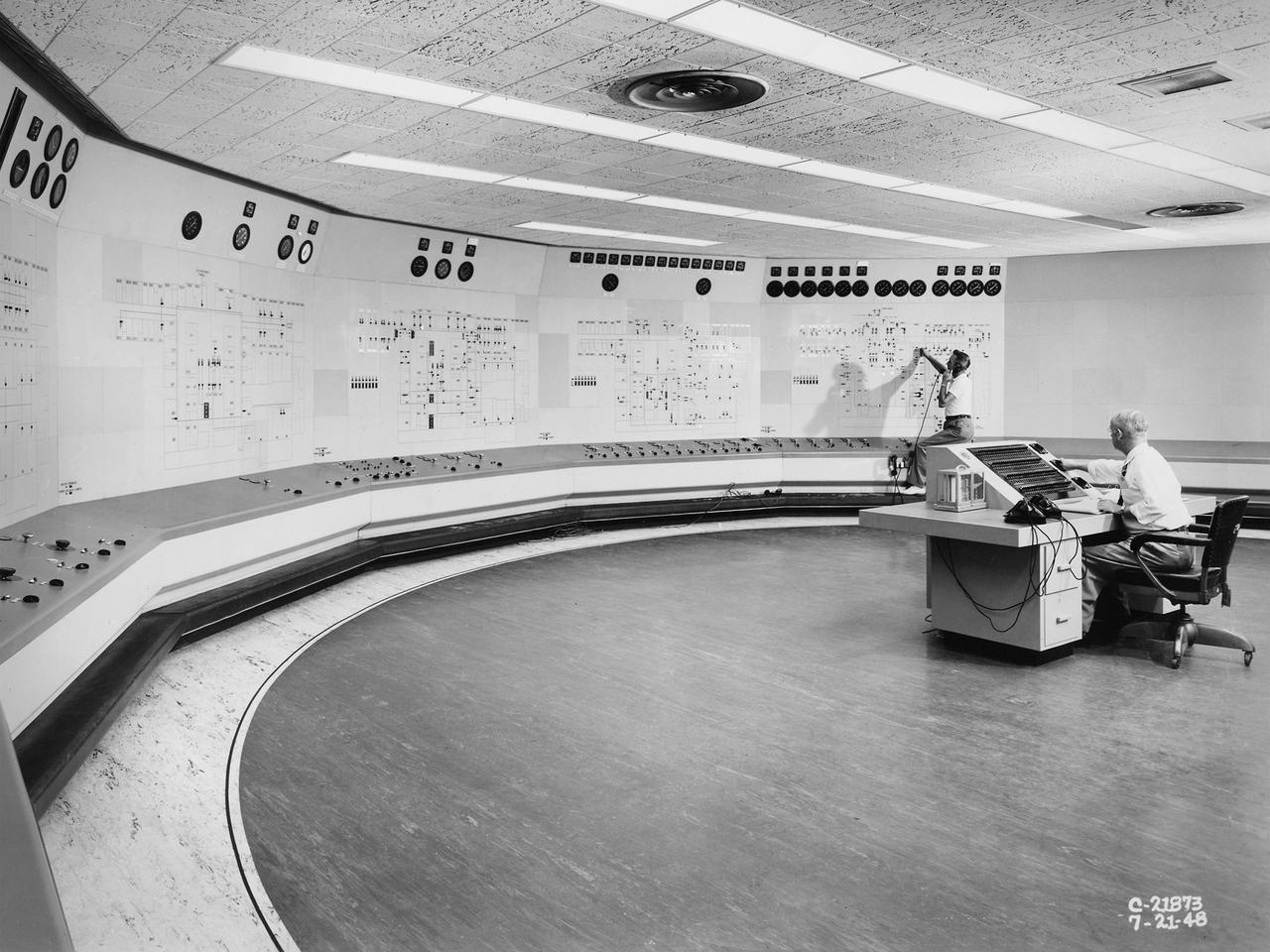
Operators in the Engine Research Building’s Central Control Room at the National Advisory Committee for Aeronautics (NACA) Lewis Flight Propulsion Laboratory. The massive 4.25-acre Engine Research Building contains dozens of test cells, test stands, and altitude chambers. A powerful collection of compressors and exhausters located in the central portion of the basement provided process air and exhaust for these test areas. This system is connected to similar process air systems in the laboratory’s other large test facilities. The Central Control Room coordinates this activity and communicates with the local utilities. This photograph was taken just after a major upgrade to the control room in 1948. The panels on the wall contain rudimentary floor plans of the different Engine Research Building sections with indicator lights and instrumentation for each test cell. The process air equipment included 12 exhausters, four compressors, a refrigeration system, cooling water, and an exhaust system. The operators in the control room kept in contact with engineers running the process air system and those conducting the tests in the test cells. The operators also coordinated with the local power companies to make sure enough electricity was available to operate the powerful compressors and exhausters.
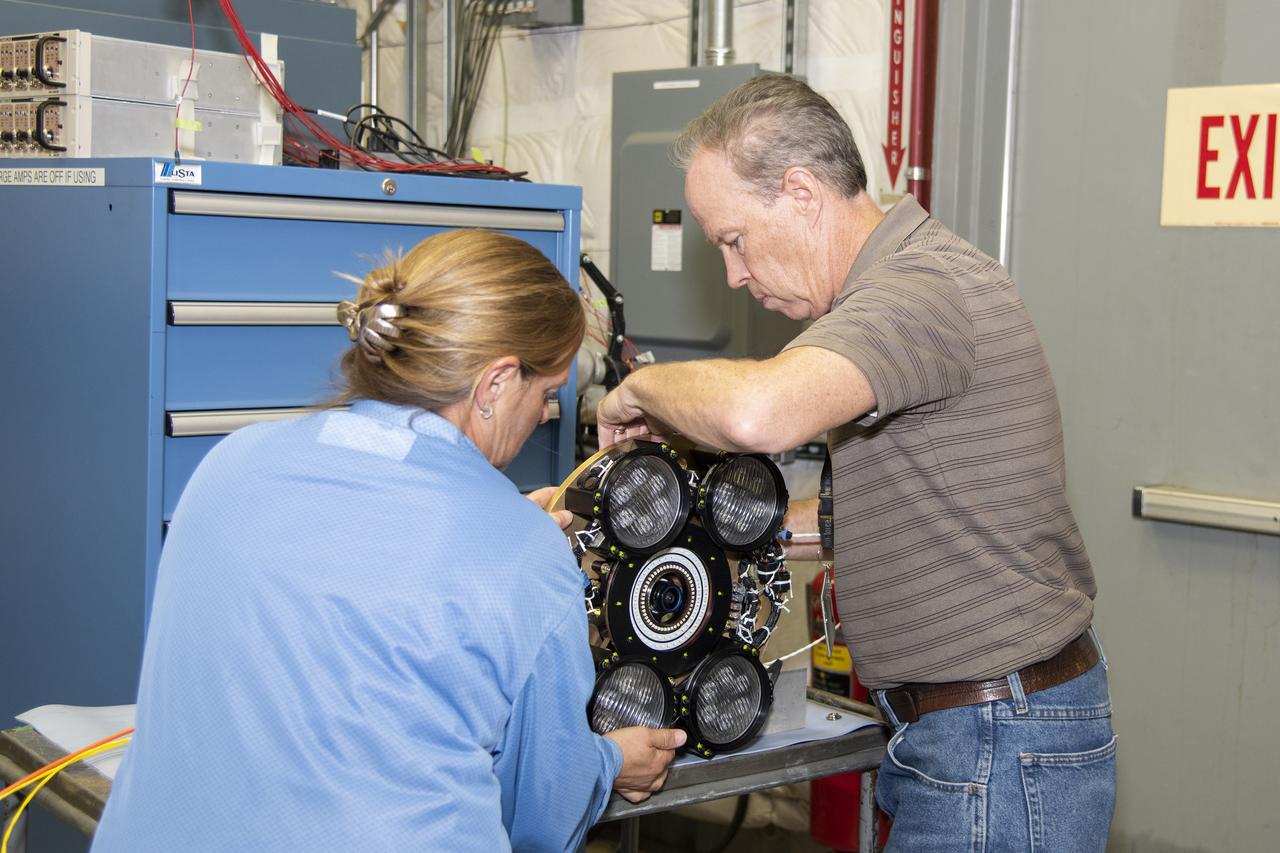
Dan Nolan, who with engineer Lucas Moxey developed the camera system shown in the photo, is seen working with April Torres to prepare it for vibration testing at NASA’s Armstrong Flight Research Center. The camera system is designed to operate as part of the Orion AA-2 test article’s abort test booster/separation ring developmental flight instrumentation subsystem. The testing proved the camera system could function and endure the predicted flight environment.
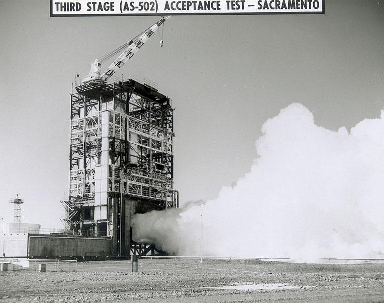
The J-2 engine for Saturn V S-IVB (third) stage blasted from the test stand at Douglas Aircraft Co., Sacramento Test Operation (SACTO) facility in California. This third stage was used on the unmarned Saturn V flight of Apollo 6 in April 1968.
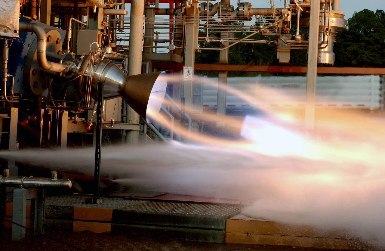
In this photo, an RS-88 development rocket engine is being test fired at NASA's Marshall Space Flight Center in Huntsville, Alabama, in support of the Pad Abort Demonstration (PAD) test flights for NASA's Orbital Space Plane (OSP). The tests could be instrumental in developing the first crew launch escape system in almost 30 years. Paving the way for a series of integrated PAD test flights, the engine tests support development of a system that could pull a crew safely away from danger during liftoff. A series of 16 hot fire tests of a 50,000-pound thrust RS-88 rocket engine were conducted, resulting in a total of 55 seconds of successful engine operation. The engine is being developed by the Rocketdyne Propulsion and Power unit of the Boeing Company. Integrated launch abort demonstration tests in 2005 will use four RS-88 engines to separate a test vehicle from a test platform, simulating pulling a crewed vehicle away from an aborted launch. Four 156-foot parachutes will deploy and carry the vehicle to landing. Lockheed Martin is building the vehicles for the PAD tests. Seven integrated tests are plarned for 2005 and 2006.
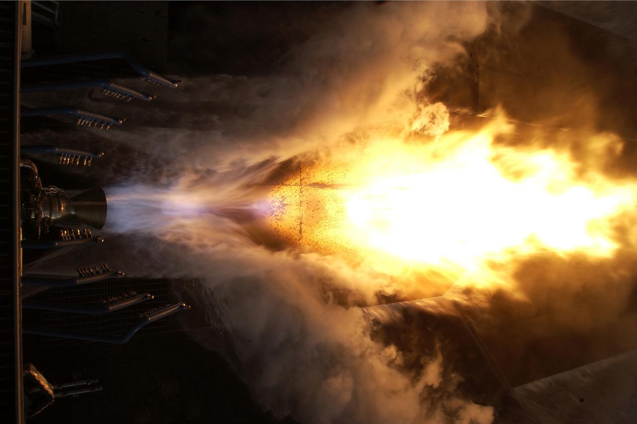
This photo gives an overhead look at an RS-88 development rocket engine being test fired at NASA's Marshall Space Flight Center in Huntsville, Alabama, in support of the Pad Abort Demonstration (PAD) test flights for NASA's Orbital Space Plane (OSP). The tests could be instrumental in developing the first crew launch escape system in almost 30 years. Paving the way for a series of integrated PAD test flights, the engine tests support development of a system that could pull a crew safely away from danger during liftoff. A series of 16 hot fire tests of a 50,000-pound thrust RS-88 rocket engine were conducted, resulting in a total of 55 seconds of successful engine operation. The engine is being developed by the Rocketdyne Propulsion and Power unit of the Boeing Company. Integrated launch abort demonstration tests in 2005 will use four RS-88 engines to separate a test vehicle from a test platform, simulating pulling a crewed vehicle away from an aborted launch. Four 156-foot parachutes will deploy and carry the vehicle to landing. Lockheed Martin is building the vehicles for the PAD tests. Seven integrated tests are plarned for 2005 and 2006.
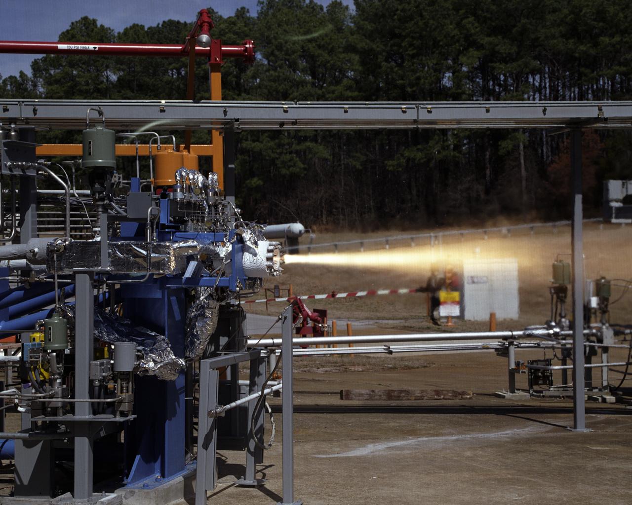
Engineers at the Marshall Space Flight Center (MSFC) have begun a series of engine tests on a new breed of space propulsion: a Reaction Control Engine developed for the Space Launch Initiative (SLI). The engine, developed by TRW Space and Electronics of Redondo Beach, California, is an auxiliary propulsion engine designed to maneuver vehicles in orbit. It is used for docking, reentry, attitude control, and fine-pointing while the vehicle is in orbit. The engine uses nontoxic chemicals as propellants, a feature that creates a safer environment for ground operators, lowers cost, and increases efficiency with less maintenance and quicker turnaround time between missions. Testing includes 30 hot-firings. This photograph shows the first engine test performed at MSFC that includes SLI technology. Another unique feature of the Reaction Control Engine is that it operates at dual thrust modes, combining two engine functions into one engine. The engine operates at both 25 and 1,000 pounds of force, reducing overall propulsion weight and allowing vehicles to easily maneuver in space. The low-level thrust of 25 pounds of force allows the vehicle to fine-point maneuver and dock while the high-level thrust of 1,000 pounds of force is used for reentry, orbit transfer, and coarse positioning. SLI is a NASA-wide research and development program, managed by the MSFC, designed to improve safety, reliability, and cost effectiveness of space travel for second generation reusable launch vehicles.
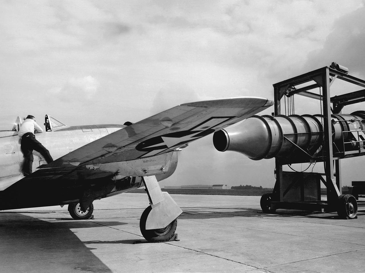
A Republic P-47G Thunderbolt is tested with a large blower on the hangar apron at the National Advisory Committee for Aeronautics (NACA) Aircraft Engine Research Laboratory in Cleveland, Ohio. The blower could produce air velocities up to 250 miles per hour. This was strong enough to simulate take-off power and eliminated the need to risk flights with untried engines. The Republic P-47G was loaned to the laboratory to test NACA modifications to the Wright R-2800 engine’s cooling system at higher altitudes. The ground-based tests, seen here, were used to map the engine’s normal operating parameters. The P-47G then underwent an extensive flight test program to study temperature distribution among the engine’s 18 cylinders and develop methods to improve that distribution.
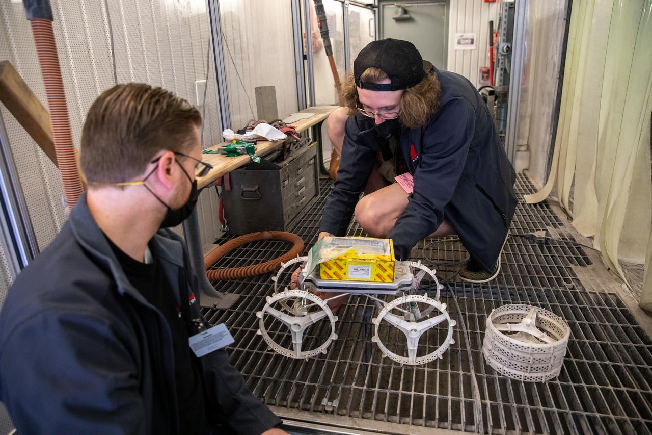
Astrobotic employees Troy Arbuckle, at left, Planetary Mobility lead mechanical engineer, and Taylor Whitaker, flight software engineer, prepare the Astrobotic CubeRover for its test run in the Granular Mechanics and Regolith Operations Laboratory regolith bin at NASA’s Kennedy Space Center in Florida on Dec. 10, 2020. The regolith bin simulates the mechanical properties of the Moon’s surface. NASA and Astrobotic employees put the CubeRover through a series of more than 150 mobility tests over several days to evaluate and improve wheel design.

The Flight Operations crew stands before a Republic P-47G Thunderbolt at the National Advisory Committee for Aeronautics (NACA) Aircraft Engine Research Laboratory in Cleveland, Ohio. The laboratory’s Flight Research Section was responsible for conducting a variety of research flights. During World War II most of the test flights complemented the efforts in ground-based facilities to improve engine cooling systems or study advanced fuel mixtures. The Republic P–47G was loaned to the laboratory to test NACA modifications to the Wright R–2800 engine’s cooling system at higher altitudes. The laboratory has always maintained a fleet of aircraft so different research projects were often conducted concurrently. The flight research program requires an entire section of personnel to accomplish its work. This staff generally consists of a flight operations group, which includes the section chief, pilots and administrative staff; a flight maintenance group with technicians and mechanics responsible for inspecting aircraft, performing checkouts and installing and removing flight instruments; and a flight research group that integrates the researchers’ experiments into the aircraft. The staff at the time of this March 1944 photograph included 3 pilots, 16 planning and analysis engineers, 36 mechanics and technicians, 10 instrumentation specialists, 6 secretaries and 5 computers.
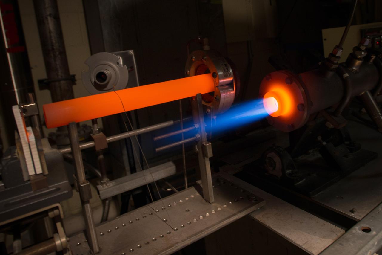
The Fuel Burner Rig is a test laboratory at NASA Glenn, which subjects new jet engine materials, treated with protective coatings, to the hostile, high temperature, high velocity environment found inside aircraft turbine engines. These samples face 200-mile per hour flames to simulate the temperatures of aircraft engines in flight. The rig can also simulate aircraft carrier and dusty desert operations where salt and sand can greatly reduce engine life and performance.

NASA engineers put the X-57 Maxwell, NASA's first all-electric X-plane, through its initial telemetry tests at NASA's Armstrong Flight Research Center in California, testing the aircraft's ability to transmit data to teams on the ground. The data is packaged and transmitted down to ground assets, where it's decoded into a format that can be presented to a flight control team to look at screens in real time for flight operations. X-57's goal is to help set certification standards for emerging electric aircraft markets.
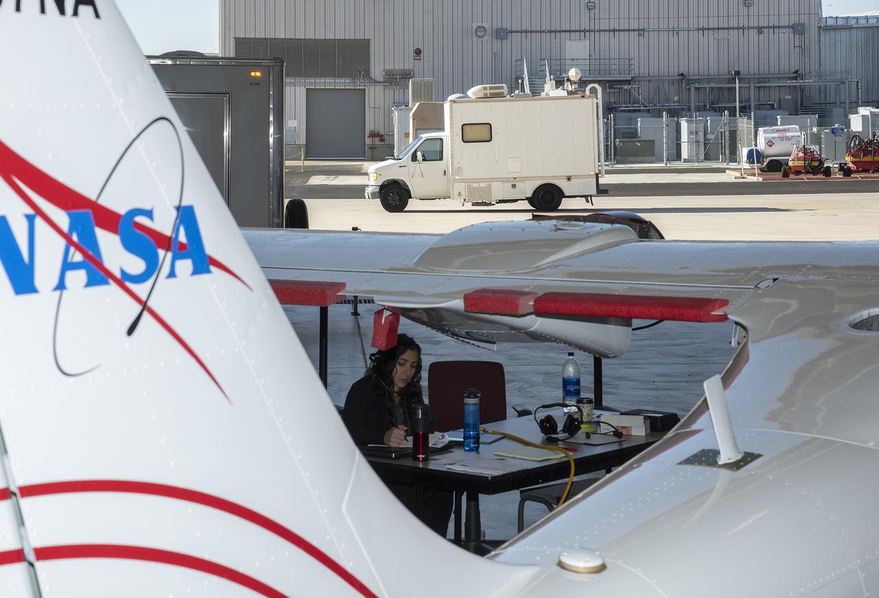
NASA engineers put the X-57 Maxwell, NASA's first all-electric X-plane, through its initial telemetry tests at NASA's Armstrong Flight Research Center in California, testing the aircraft's ability to transmit data to teams on the ground. The data is packaged and transmitted down to ground assets, where it's decoded into a format that can be presented to a flight control team to look at screens in real time for flight operations. X-57's goal is to help set certification standards for emerging electric aircraft markets.
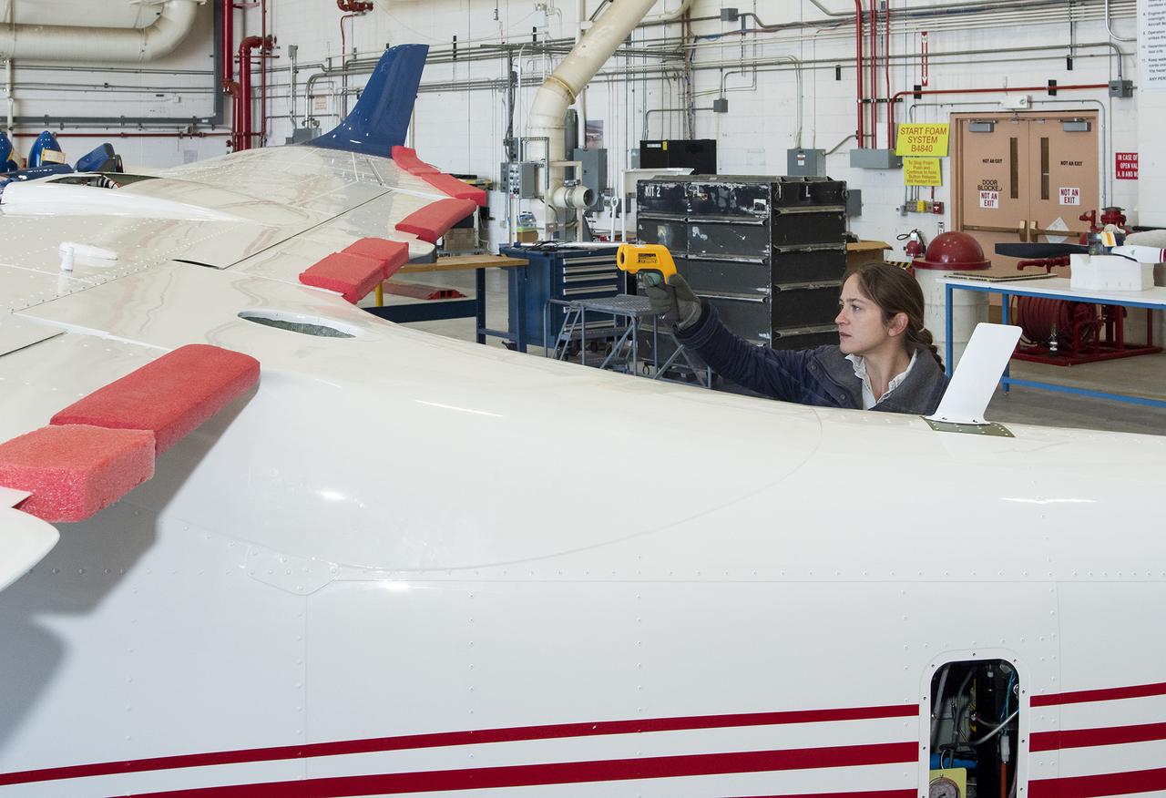
NASA engineers put the X-57 Maxwell, NASA’s first all-electric X-plane, through its initial telemetry tests at NASA’s Armstrong Flight Research Center in California, testing the aircraft’s ability to transmit data to teams on the ground. The data is packaged and transmitted down to ground assets, where it’s decoded into a format that can be presented to a flight control team to look at screens in real time for flight operations. X-57’s goal is to help set certification standards for emerging electric aircraft markets.
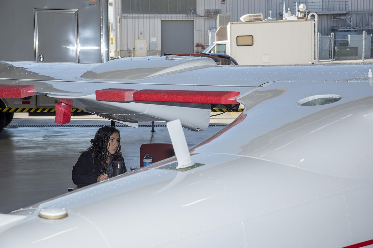
NASA engineers put the X-57 Maxwell, NASA’s first all-electric X-plane, through its initial telemetry tests at NASA’s Armstrong Flight Research Center in California, testing the aircraft’s ability to transmit data to teams on the ground. The data is packaged and transmitted down to ground assets, where it’s decoded into a format that can be presented to a flight control team to look at screens in real time for flight operations. X-57’s goal is to help set certification standards for emerging electric aircraft markets.
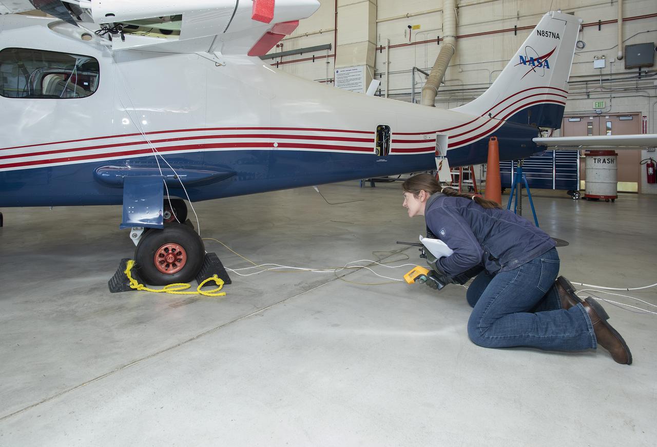
NASA engineers put the X-57 Maxwell, NASA’s first all-electric X-plane, through its initial telemetry tests at NASA’s Armstrong Flight Research Center in California, testing the aircraft’s ability to transmit data to teams on the ground. The data is packaged and transmitted down to ground assets, where it’s decoded into a format that can be presented to a flight control team to look at screens in real time for flight operations. X-57’s goal is to help set certification standards for emerging electric aircraft markets.
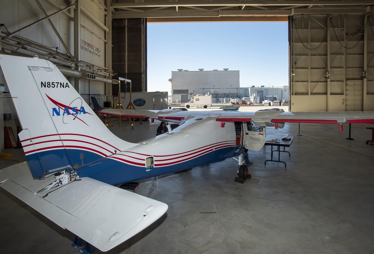
NASA engineers put the X-57 Maxwell, NASA's first all-electric X-plane, through its initial telemetry tests at NASA's Armstrong Flight Research Center in California, testing the aircraft's ability to transmit data to teams on the ground. The data is packaged and transmitted down to ground assets, where it's decoded into a format that can be presented to a flight control team to look at screens in real time for flight operations. X-57's goal is to help set certification standards for emerging electric aircraft markets.
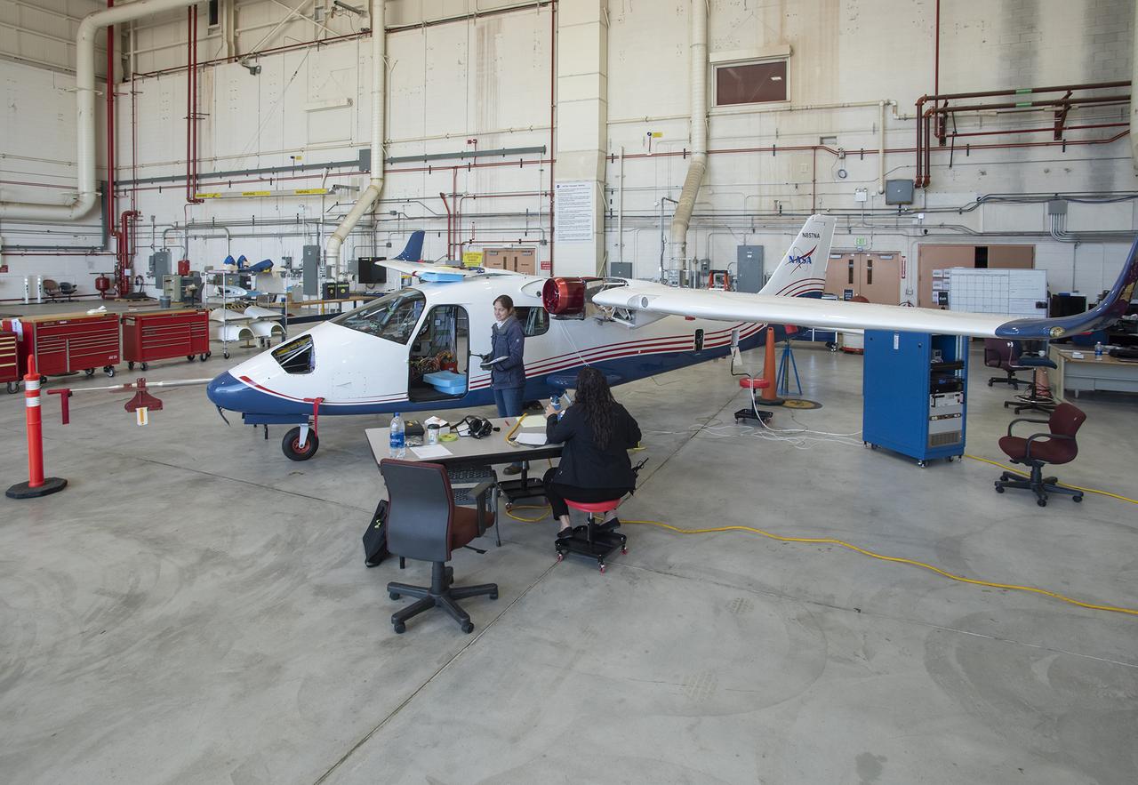
NASA engineers put the X-57 Maxwell, NASA’s first all-electric X-plane, through its initial telemetry tests at NASA’s Armstrong Flight Research Center in California, testing the aircraft’s ability to transmit data to teams on the ground. The data is packaged and transmitted down to ground assets, where it’s decoded into a format that can be presented to a flight control team to look at screens in real time for flight operations. X-57’s goal is to help set certification standards for emerging electric aircraft markets.

Engineers at NASA‘s Armstrong Flight Research Center sit in a control room to monitor the remotely-piloted Ikhana aircraft during a test flight. The test flight was used to validate key technologies and operations necessary to receive approval from the FAA’s to fly the aircraft in the National Airspace System June 12, 2018, without a safety chase aircraft.
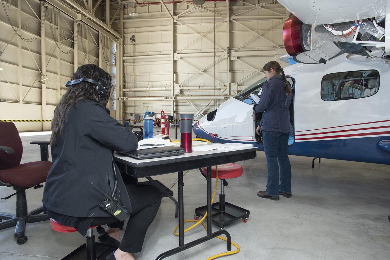
NASA engineers put the X-57 Maxwell, NASA's first all-electric X-plane, through its initial telemetry tests at NASA's Armstrong Flight Research Center in California, testing the aircraft's ability to transmit data to teams on the ground. The data is packaged and transmitted down to ground assets, where it's decoded into a format that can be presented to a flight control team to look at screens in real time for flight operations. X-57's goal is to help set certification standards for emerging electric aircraft markets.
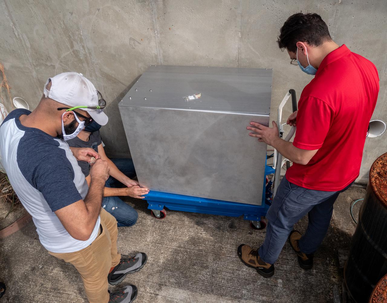
Thermal/Fluid Analysis Engineer Malay Shah, left, and Ray Pitts, co-principal investigator for the Orbital Syngas Commodity Augmentation Reactor (OSCAR), prepare OSCAR for thermal testing Jan. 26, 2021, at NASA’s Kennedy Space Center in Florida. The tests are in preparation for a scheduled suborbital flight test later this year facilitated by NASA’s Flight Opportunities program. The testing ensures the thermal environment of the payload won’t create additional hazards during flight and that OSCAR can successfully operate within the temperature range it may encounter as it performs tests in microgravity.
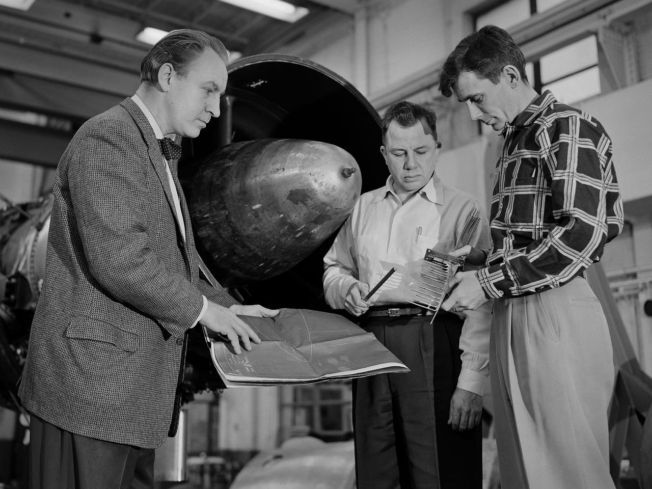
Researcher Bill Reiwaldt discusses the preparations for a test in the Altitude Wind Tunnel with technicians Jack Wagner and Dick Golladay at the National Advisory Committee for Aeronautics (NACA) Lewis Flight Propulsion Laboratory. Research engineers developed ideas for tests that were often in response to requests from the military or aircraft industry. Arrangements were made to obtain an engine for the study and to transport it to the Cleveland laboratory. The engine was brought into the facility’s shop area, where it was readied for investigation. It was common for several different engines to be worked on simultaneously in the shop. The researcher would discuss the engine and the test objectives with the Test Installation Division and the facility’s technicians. The operations team would handle the installation of the instrumentation and fitting the test into the facility’s schedule. Upon completion of the previous test, the engine was removed. The next engine was lifted by an overhead crane and transported from the shop to the test section. The engine was connected to the measurement devices and fuel and oil supply lines. Engines were tested over numerous runs under varying conditions and with variations on the configuration. The findings and test procedure were then described in research or technical memorandums and distributed to industry.
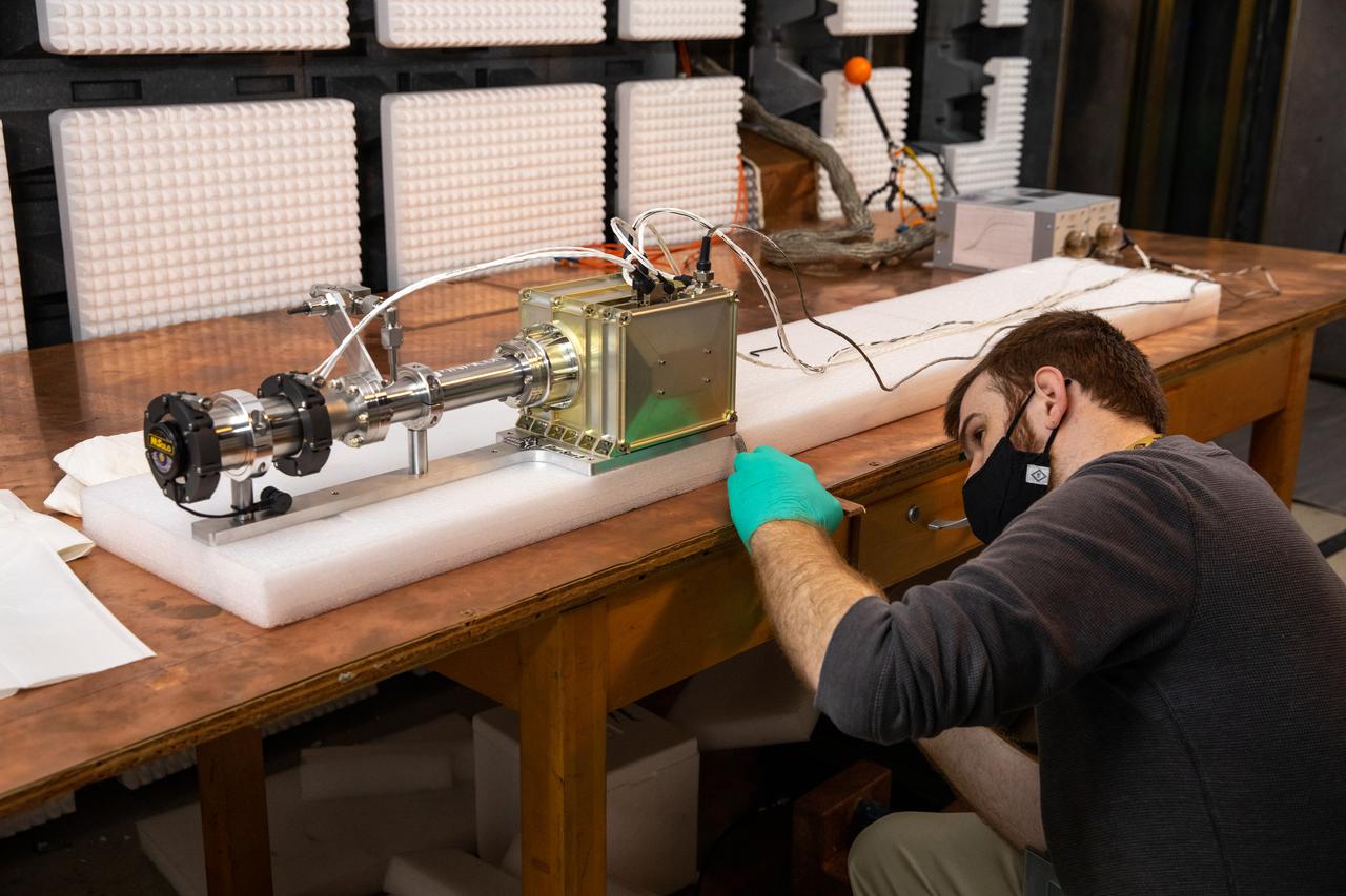
Electronics Engineer and Mass Spectrometer Observing Lunar Operations (MSolo) team member Nate Cain conducts electromagnetic interference (EMI) testing inside the EMI Laboratory at NASA’s Kennedy Space Center in Florida on Feb. 14, 2022. The tests will verify that MSolo can control the emissions it will produce during its missions and meets EMI susceptibility requirements as part of its preparation to operate in the lunar environment. The third MSolo to go through EMI testing, this is an engineering development unit representative of the flight unit manifested to fly to the Moon’s South Pole as a payload on the agency’s Volatiles Investigating Polar Exploration Rover (VIPER) in 2023. Researchers and engineers are preparing MSolo instruments to launch on four robotic missions as part of NASA’s Commercial Lunar Payload Services (CLPS) – the first of which is slated for later this year. MSolo will help analyze the chemical makeup of landing sites on the Moon, with the later missions also studying water on the lunar surface.

Electronics Engineer and Mass Spectrometer Observing Lunar Operations (MSolo) team member Nate Cain conducts electromagnetic interference (EMI) testing inside the EMI Laboratory at NASA’s Kennedy Space Center in Florida on Feb. 14, 2022. The tests will verify that MSolo can control the emissions it will produce during its missions and meets EMI susceptibility requirements as part of its preparation to operate in the lunar environment. The third MSolo to go through EMI testing, this is an engineering development unit representative of the flight unit manifested to fly to the Moon’s South Pole as a payload on the agency’s Volatiles Investigating Polar Exploration Rover (VIPER) in 2023. Researchers and engineers are preparing MSolo instruments to launch on four robotic missions as part of NASA’s Commercial Lunar Payload Services (CLPS) – the first of which is slated for later this year. MSolo will help analyze the chemical makeup of landing sites on the Moon, with the later missions also studying water on the lunar surface.
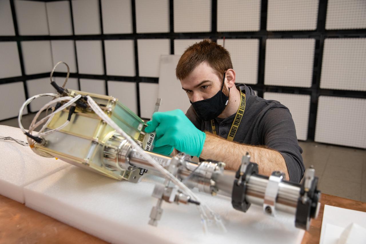
Electronics Engineer and Mass Spectrometer Observing Lunar Operations (MSolo) team member Nate Cain conducts electromagnetic interference (EMI) testing inside the EMI Laboratory at NASA’s Kennedy Space Center in Florida on Feb. 14, 2022. These tests will verify that MSolo can control the emissions it will produce during its missions and meets EMI susceptibility requirements as part of its preparation to operate in the lunar environment. The third MSolo to go through EMI testing, this is an engineering development unit representative of the flight unit manifested to fly to the Moon’s South Pole as a payload on the agency’s Volatiles Investigating Polar Exploration Rover (VIPER) in 2023. Researchers and engineers are preparing MSolo instruments to launch on four robotic missions as part of NASA’s Commercial Lunar Payload Services (CLPS) – the first of which is slated for later this year. MSolo will help analyze the chemical makeup of landing sites on the Moon, with the later missions also studying water on the lunar surface.
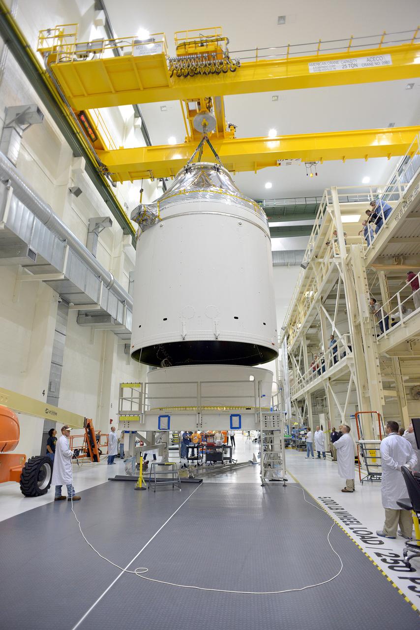
Technicians and engineers put finishing touches on the Orion Exploration Flight Test-1 (EFT-1) crew module and service module stack in the Operations and Checkout (O&C) Building at Kennedy Space Center on Sept. 7, 2014. Part of Batch image transfer from Flickr.
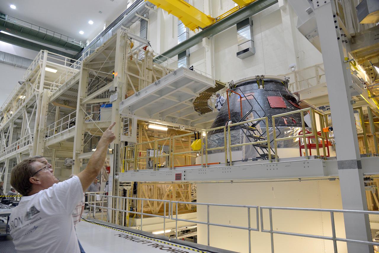
Technicians and engineers put finishing touches on the Orion Exploration Flight Test-1 (EFT-1) crew module and service module stack in the Operations and Checkout (O&C) Building at Kennedy Space Center on Sept. 7, 2014. Part of Batch image transfer from Flickr.
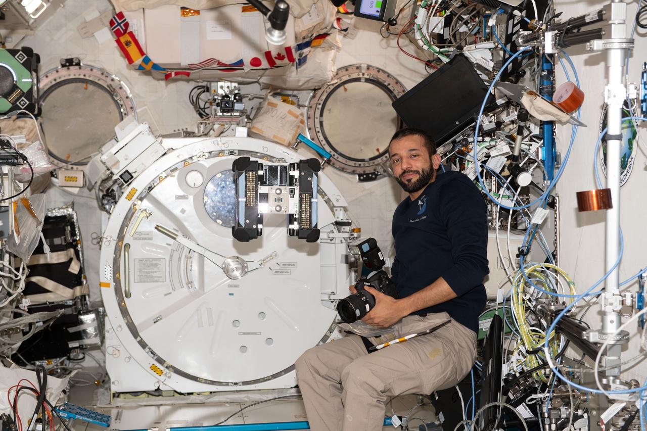
iss069e011345 (May 16, 2023) --- UAE (United Arab Emirates) astronaut and Expedition 69 Flight Engineer Sultan Alneyadi observes a free-flying Astrobee robotic assistant during the testing of its operations for an upcoming student competition to control the robotic devices.
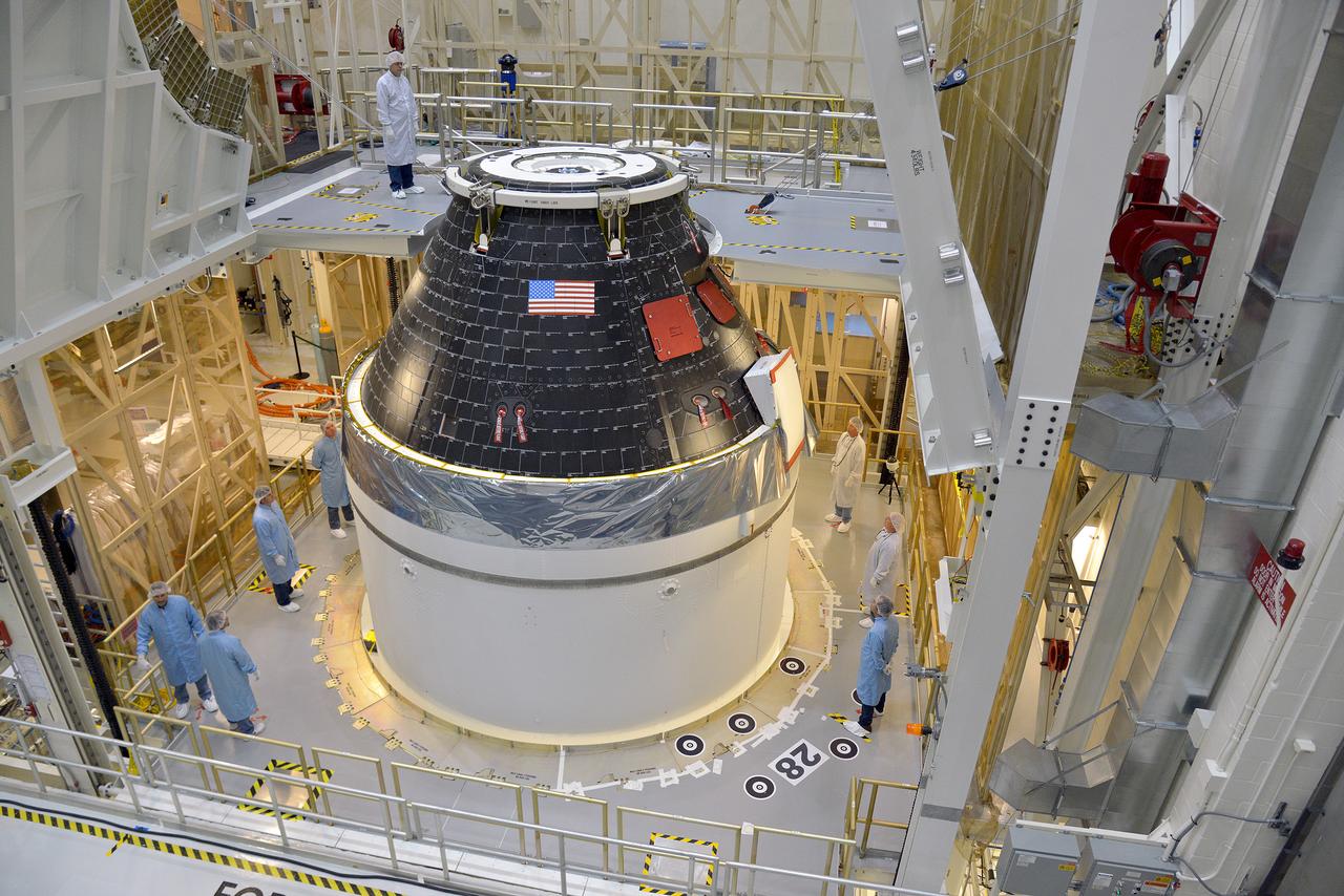
Technicians and engineers put finishing touches on the Orion Exploration Flight Test-1 (EFT-1) crew module and service module stack in the Operations and Checkout (O&C) Building at Kennedy Space Center on Sept. 7, 2014. Part of Batch image transfer from Flickr.
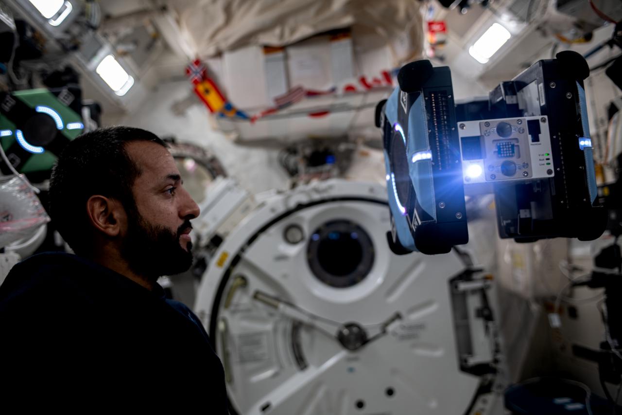
iss069e010815 (May 16, 2023) --- UAE (United Arab Emirates) astronaut and Expedition 69 Flight Engineer Sultan Alneyadi observes a free-flying Astrobee robotic assistant during the testing of its operations for an upcoming student competition to control the robotic devices.

Technicians and engineers put finishing touches on the Orion Exploration Flight Test-1 (EFT-1) crew module and service module stack in the Operations and Checkout (O&C) Building at Kennedy Space Center on Sept. 7, 2014. Part of Batch image transfer from Flickr.
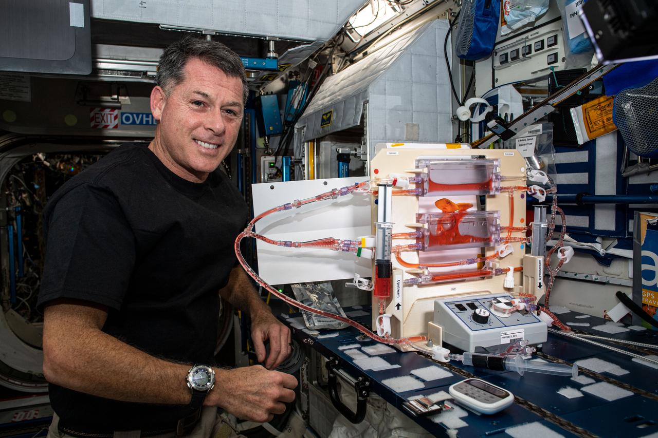
iss065e074538 (May 27, 2021) --- NASA astronaut and Expedition 65 Flight Engineer Shane Kimbrough conducts cylinder test operations for the Plant Water Management experiment. The space botany study explores hydroponics in microgravity and may also improve watering systems on Earth.
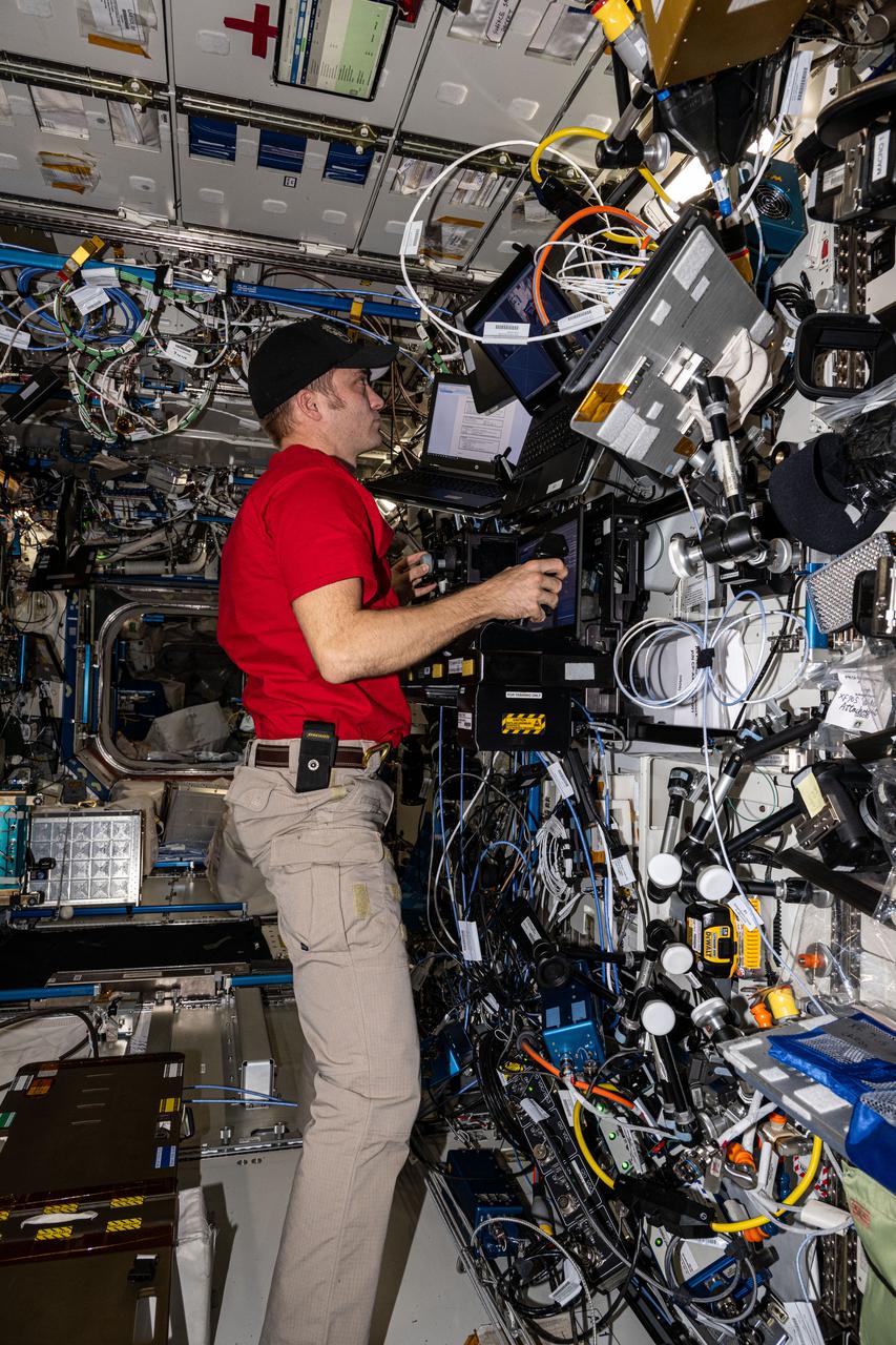
iss071e010043 (April 18, 2024) --- Expedition 71 Flight Engineer and NASA astronaut Matthew Dominick practices operating the Canadarm2 robotic arm during a proficiency test using the robotics workstation aboard the Interntional Space Station's Destiny laboratory module.
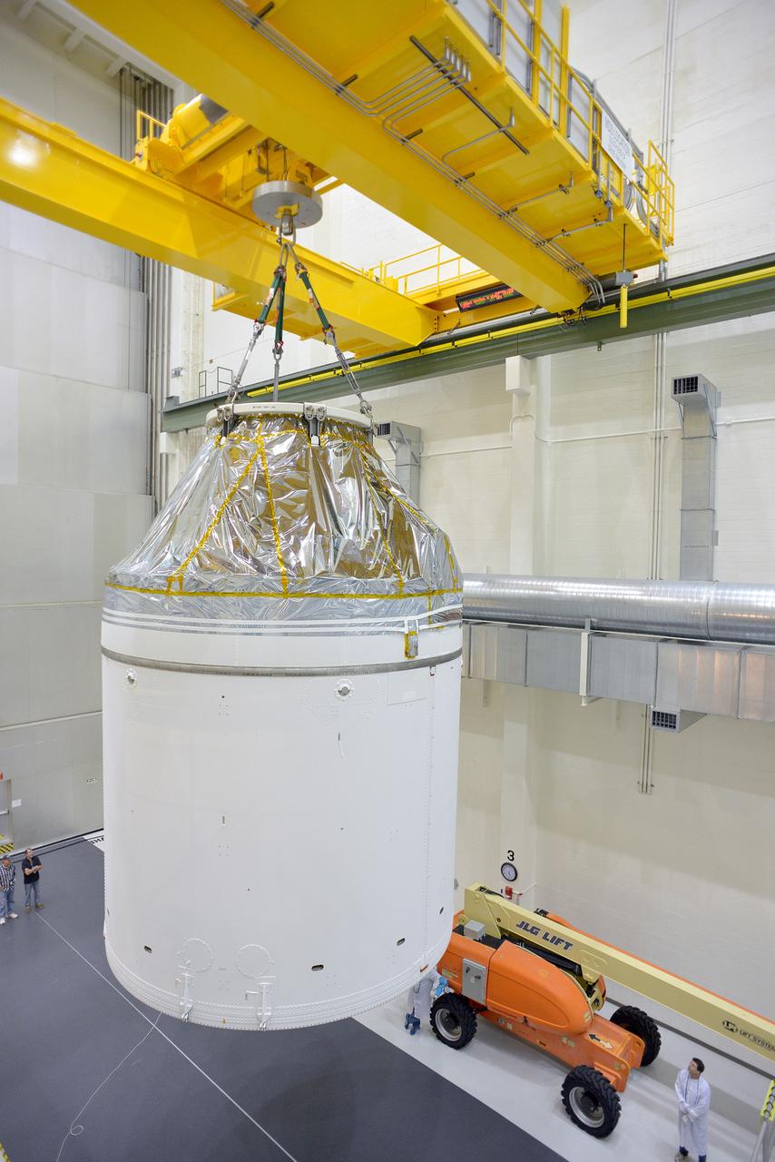
Technicians and engineers put finishing touches on the Orion Exploration Flight Test-1 (EFT-1) crew module and service module stack in the Operations and Checkout (O&C) Building at Kennedy Space Center on Sept. 7, 2014. Part of Batch image transfer from Flickr.
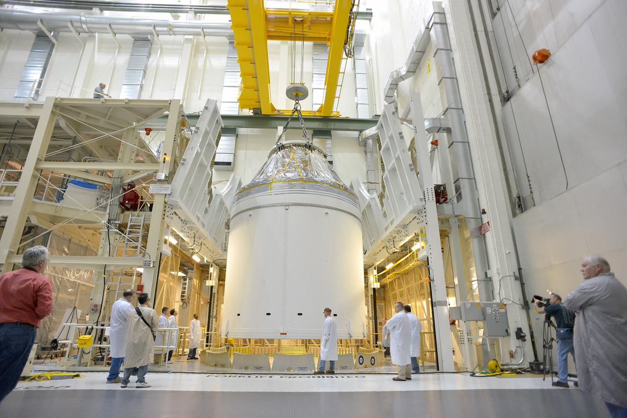
Technicians and engineers put finishing touches on the Orion Exploration Flight Test-1 (EFT-1) crew module and service module stack in the Operations and Checkout (O&C) Building at Kennedy Space Center on Sept. 7, 2014. Part of Batch image transfer from Flickr.

Technicians and engineers put finishing touches on the Orion Exploration Flight Test-1 (EFT-1) crew module and service module stack in the Operations and Checkout (O&C) Building at Kennedy Space Center on Sept. 7, 2014. Part of Batch image transfer from Flickr.
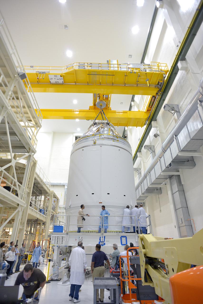
Technicians and engineers put finishing touches on the Orion Exploration Flight Test-1 (EFT-1) crew module and service module stack in the Operations and Checkout (O&C) Building at Kennedy Space Center on Sept. 7, 2014. Part of Batch image transfer from Flickr.
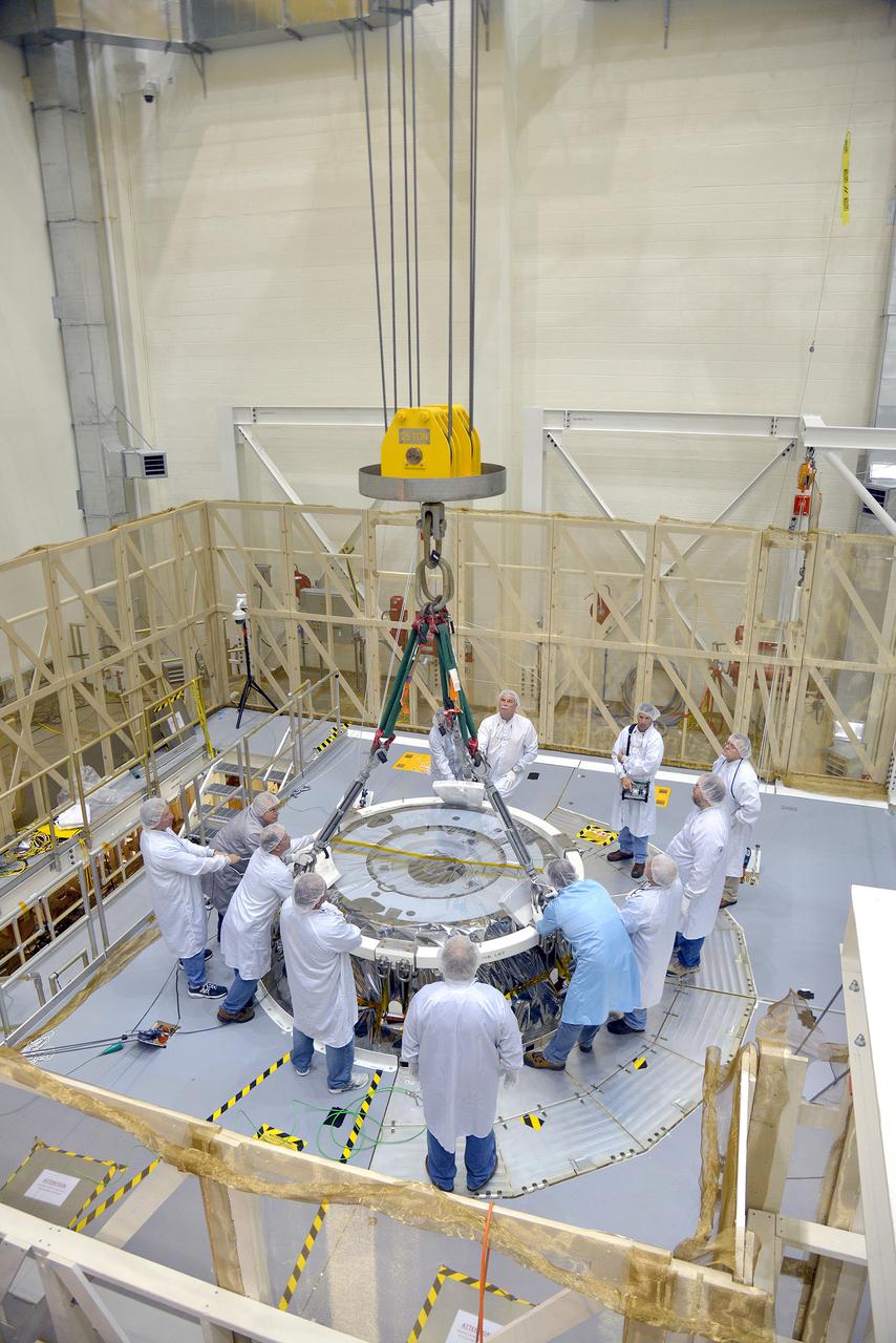
Technicians and engineers put finishing touches on the Orion Exploration Flight Test-1 (EFT-1) crew module and service module stack in the Operations and Checkout (O&C) Building at Kennedy Space Center on Sept. 7, 2014. Part of Batch image transfer from Flickr.
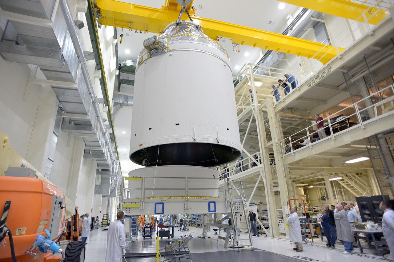
Technicians and engineers put finishing touches on the Orion Exploration Flight Test-1 (EFT-1) crew module and service module stack in the Operations and Checkout (O&C) Building at Kennedy Space Center on Sept. 7, 2014. Part of Batch image transfer from Flickr.

Technicians and engineers put finishing touches on the Orion Exploration Flight Test-1 (EFT-1) crew module and service module stack in the Operations and Checkout (O&C) Building at Kennedy Space Center on Sept. 7, 2014. Part of Batch image transfer from Flickr.
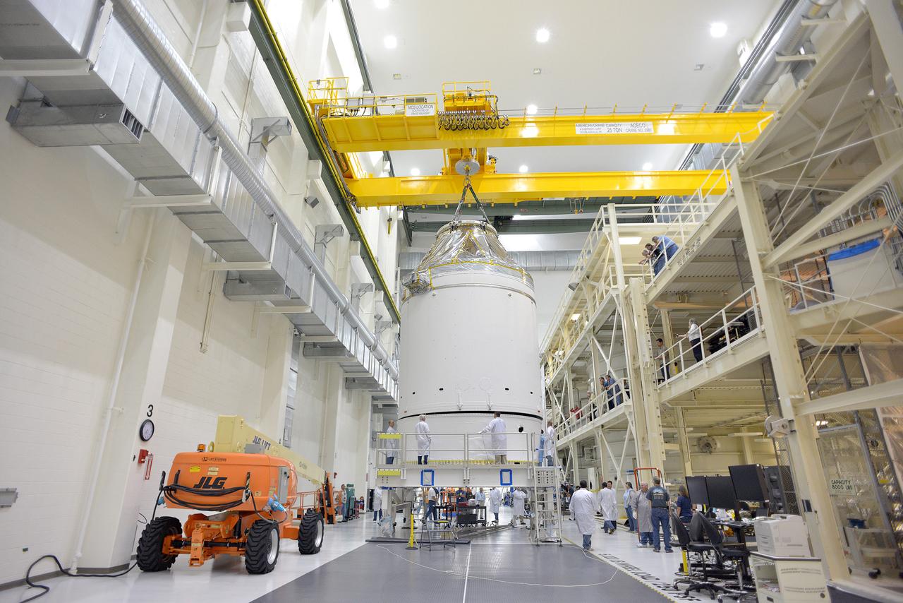
Technicians and engineers put finishing touches on the Orion Exploration Flight Test-1 (EFT-1) crew module and service module stack in the Operations and Checkout (O&C) Building at Kennedy Space Center on Sept. 7, 2014. Part of Batch image transfer from Flickr.
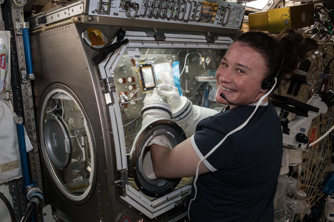
iss056e078402 (July 3, 2018) --- Flight Engineer Serena Auñón-Chancellor conducts research operations for the AngieX Cancer Therapy study inside the Microgravity Science Glovebox. The new cancer research seeks to test a safer, more effective treatment that targets tumor cells and blood vessels.
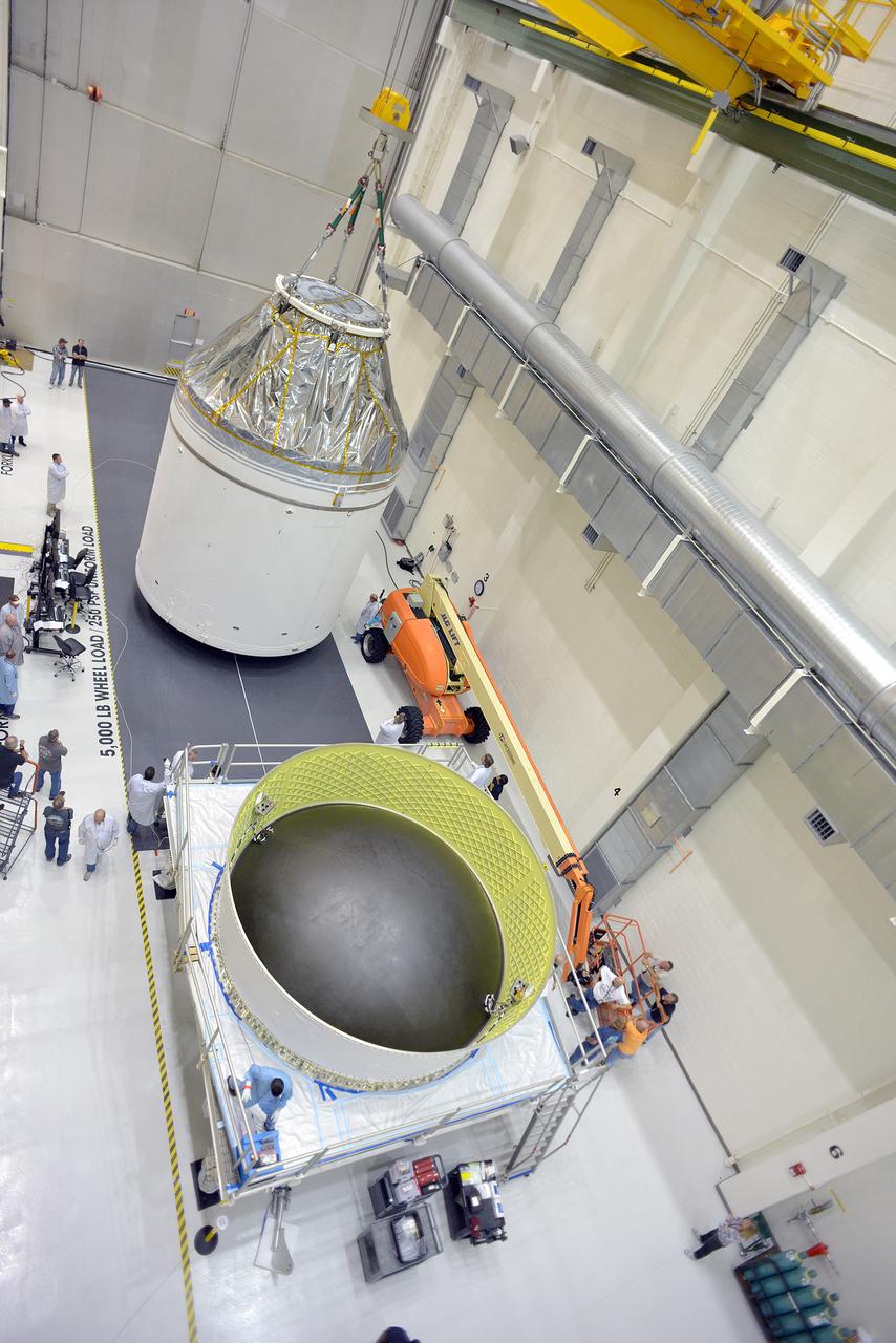
Technicians and engineers put finishing touches on the Orion Exploration Flight Test-1 (EFT-1) crew module and service module stack in the Operations and Checkout (O&C) Building at Kennedy Space Center on Sept. 7, 2014. Part of Batch image transfer from Flickr.
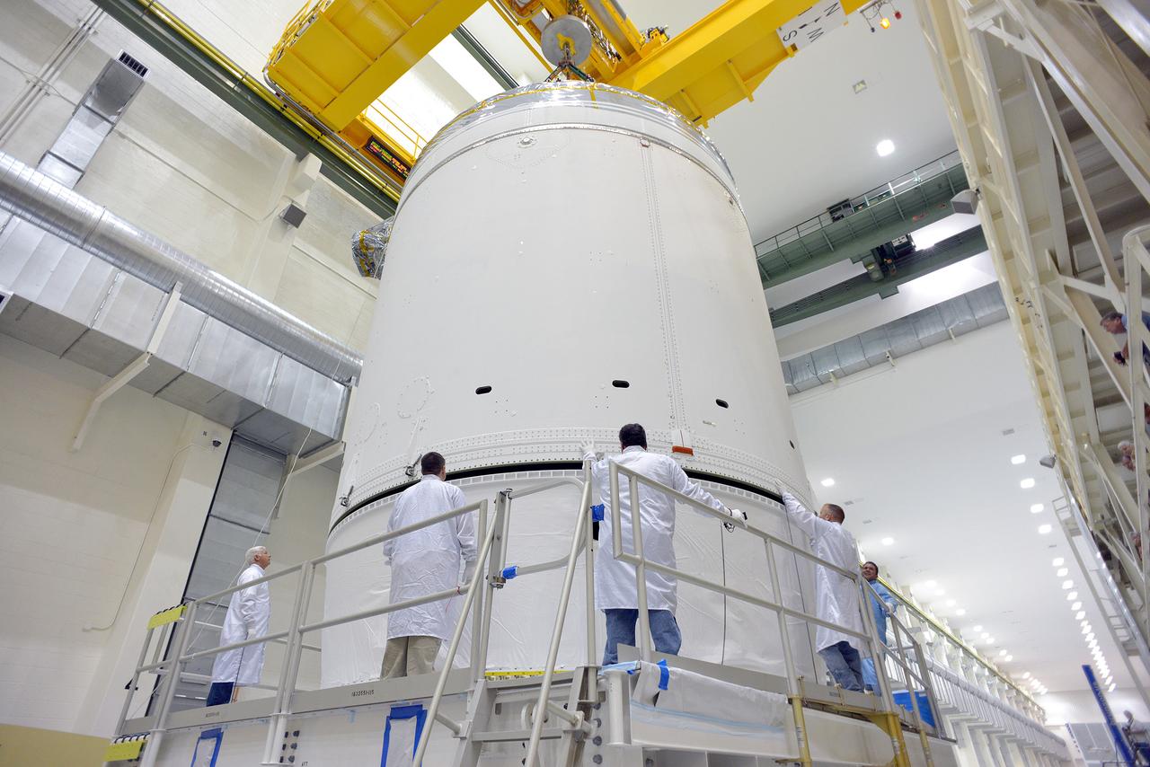
Technicians and engineers put finishing touches on the Orion Exploration Flight Test-1 (EFT-1) crew module and service module stack in the Operations and Checkout (O&C) Building at Kennedy Space Center on Sept. 7, 2014. Part of Batch image transfer from Flickr.
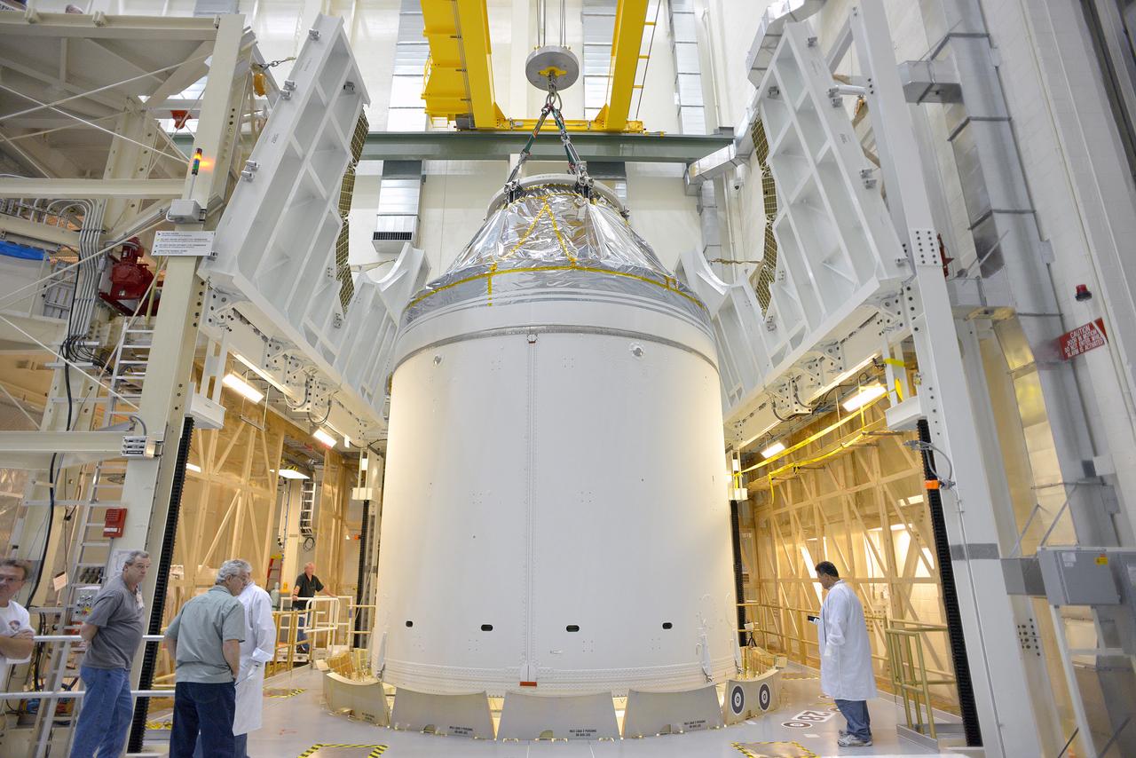
Technicians and engineers put finishing touches on the Orion Exploration Flight Test-1 (EFT-1) crew module and service module stack in the Operations and Checkout (O&C) Building at Kennedy Space Center on Sept. 7, 2014. Part of Batch image transfer from Flickr.
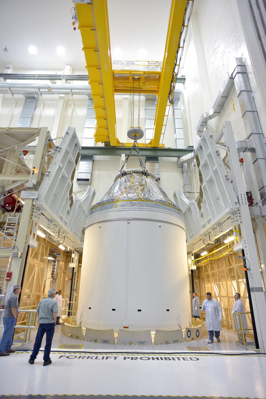
Technicians and engineers put finishing touches on the Orion Exploration Flight Test-1 (EFT-1) crew module and service module stack in the Operations and Checkout (O&C) Building at Kennedy Space Center on Sept. 7, 2014. Part of Batch image transfer from Flickr.
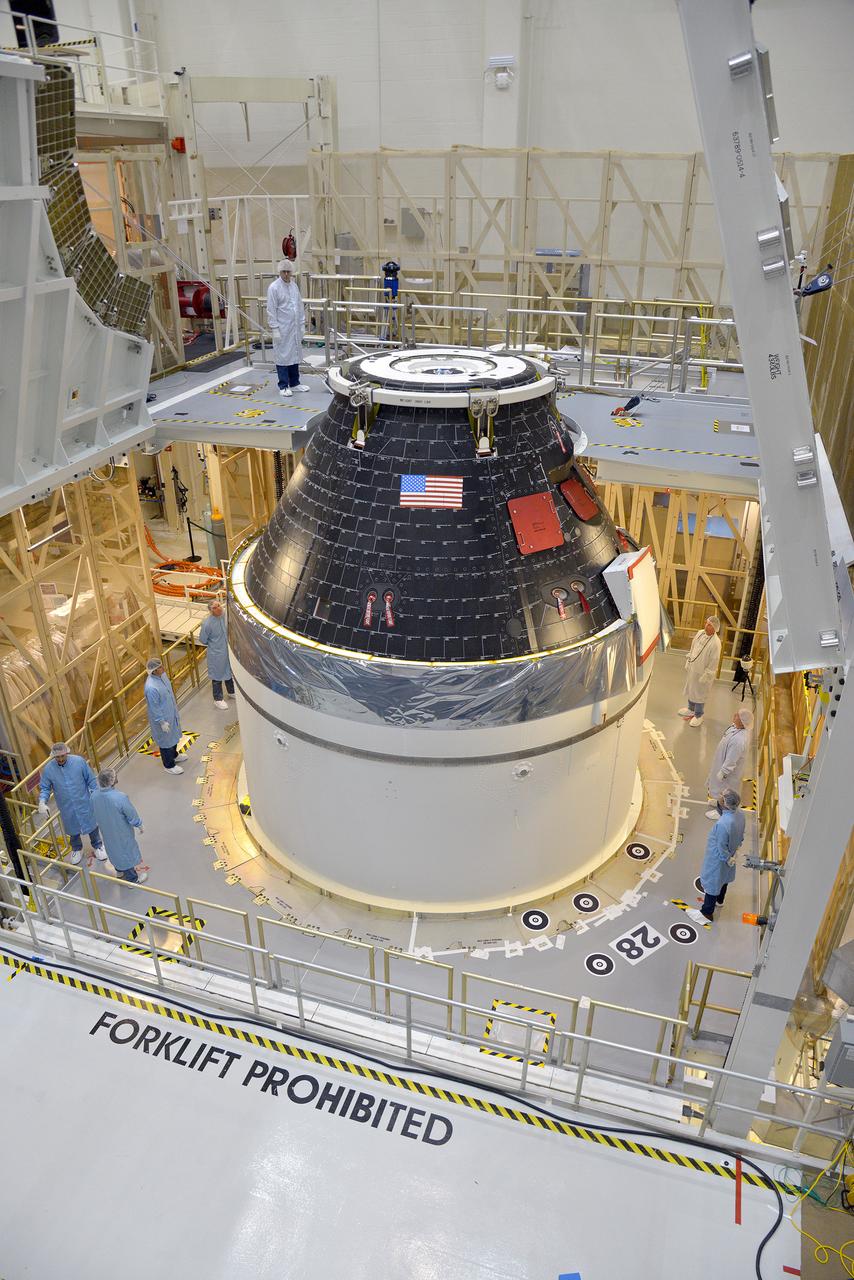
Technicians and engineers put finishing touches on the Orion Exploration Flight Test-1 (EFT-1) crew module and service module stack in the Operations and Checkout (O&C) Building at Kennedy Space Center on Sept. 7, 2014. Part of Batch image transfer from Flickr.

Technicians and engineers put finishing touches on the Orion Exploration Flight Test-1 (EFT-1) crew module and service module stack in the Operations and Checkout (O&C) Building at Kennedy Space Center on Sept. 7, 2014. Part of Batch image transfer from Flickr.
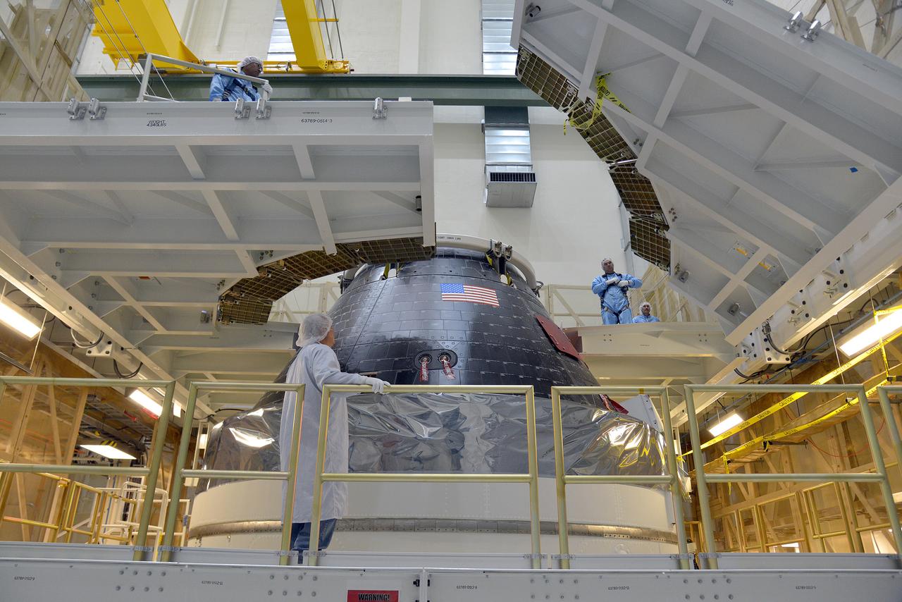
Technicians and engineers put finishing touches on the Orion Exploration Flight Test-1 (EFT-1) crew module and service module stack in the Operations and Checkout (O&C) Building at Kennedy Space Center on Sept. 7, 2014. Part of Batch image transfer from Flickr.
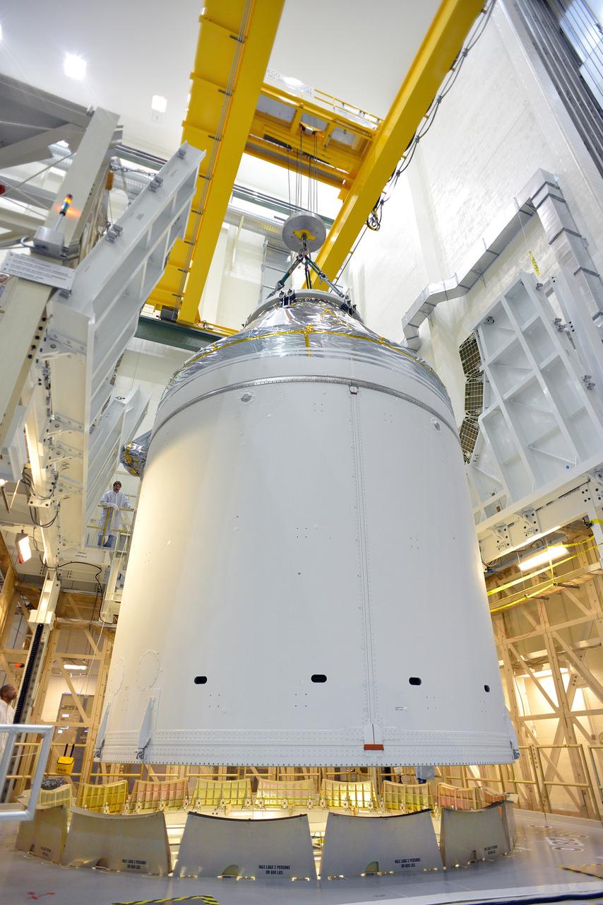
Technicians and engineers put finishing touches on the Orion Exploration Flight Test-1 (EFT-1) crew module and service module stack in the Operations and Checkout (O&C) Building at Kennedy Space Center on Sept. 7, 2014. Part of Batch image transfer from Flickr.
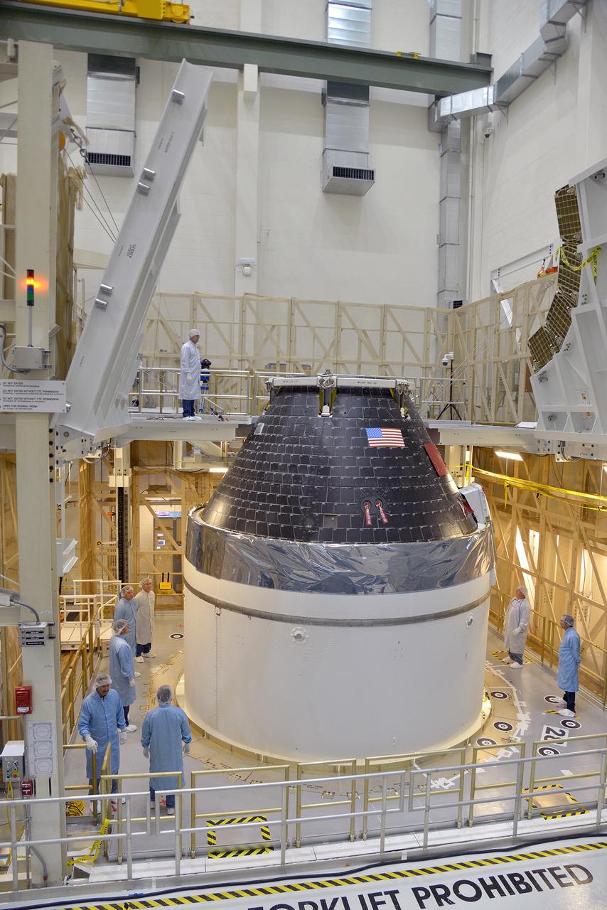
Technicians and engineers put finishing touches on the Orion Exploration Flight Test-1 (EFT-1) crew module and service module stack in the Operations and Checkout (O&C) Building at Kennedy Space Center on Sept. 7, 2014. Part of Batch image transfer from Flickr.
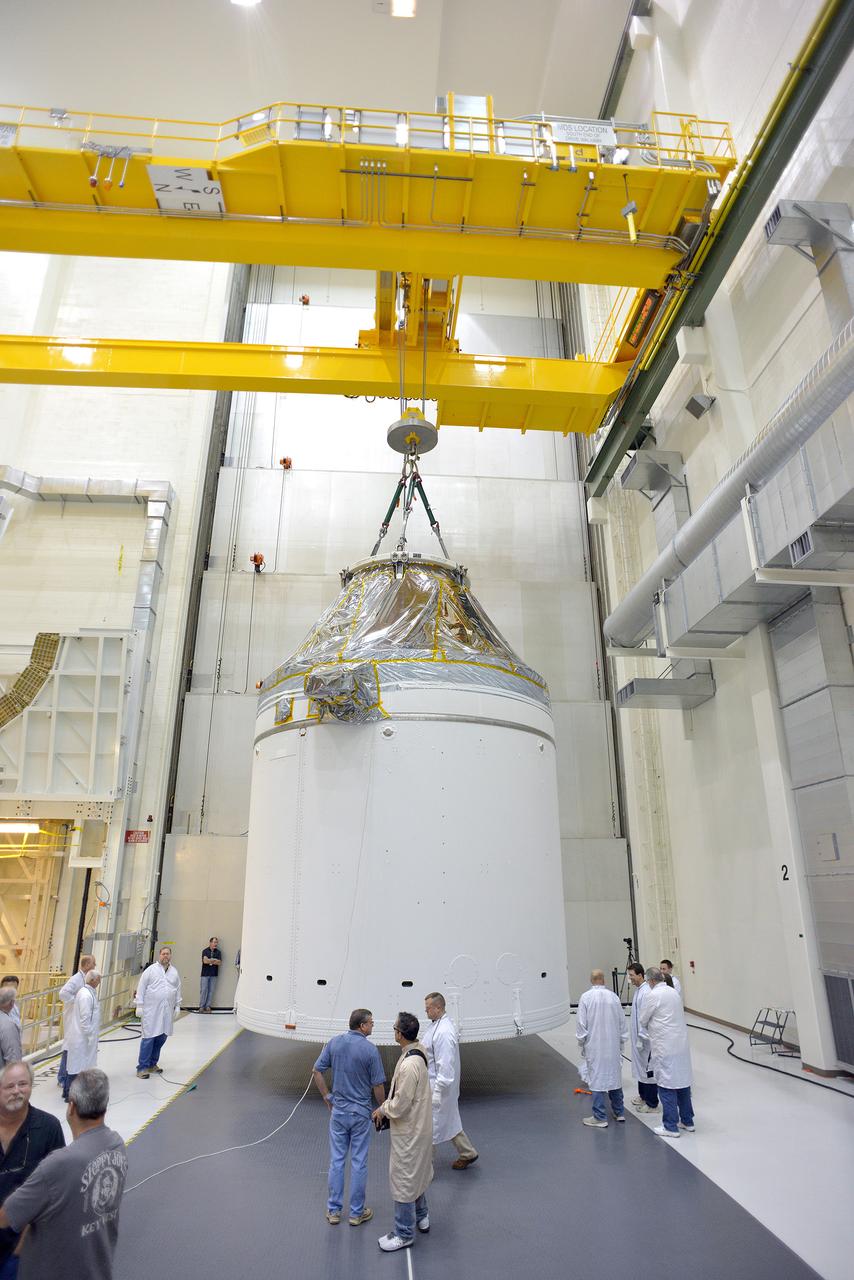
Technicians and engineers put finishing touches on the Orion Exploration Flight Test-1 (EFT-1) crew module and service module stack in the Operations and Checkout (O&C) Building at Kennedy Space Center on Sept. 7, 2014. Part of Batch image transfer from Flickr.
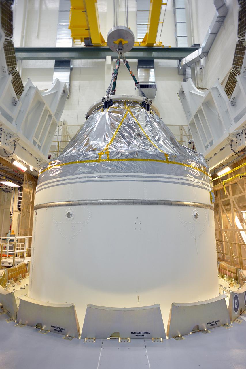
Technicians and engineers put finishing touches on the Orion Exploration Flight Test-1 (EFT-1) crew module and service module stack in the Operations and Checkout (O&C) Building at Kennedy Space Center on Sept. 7, 2014. Part of Batch image transfer from Flickr.
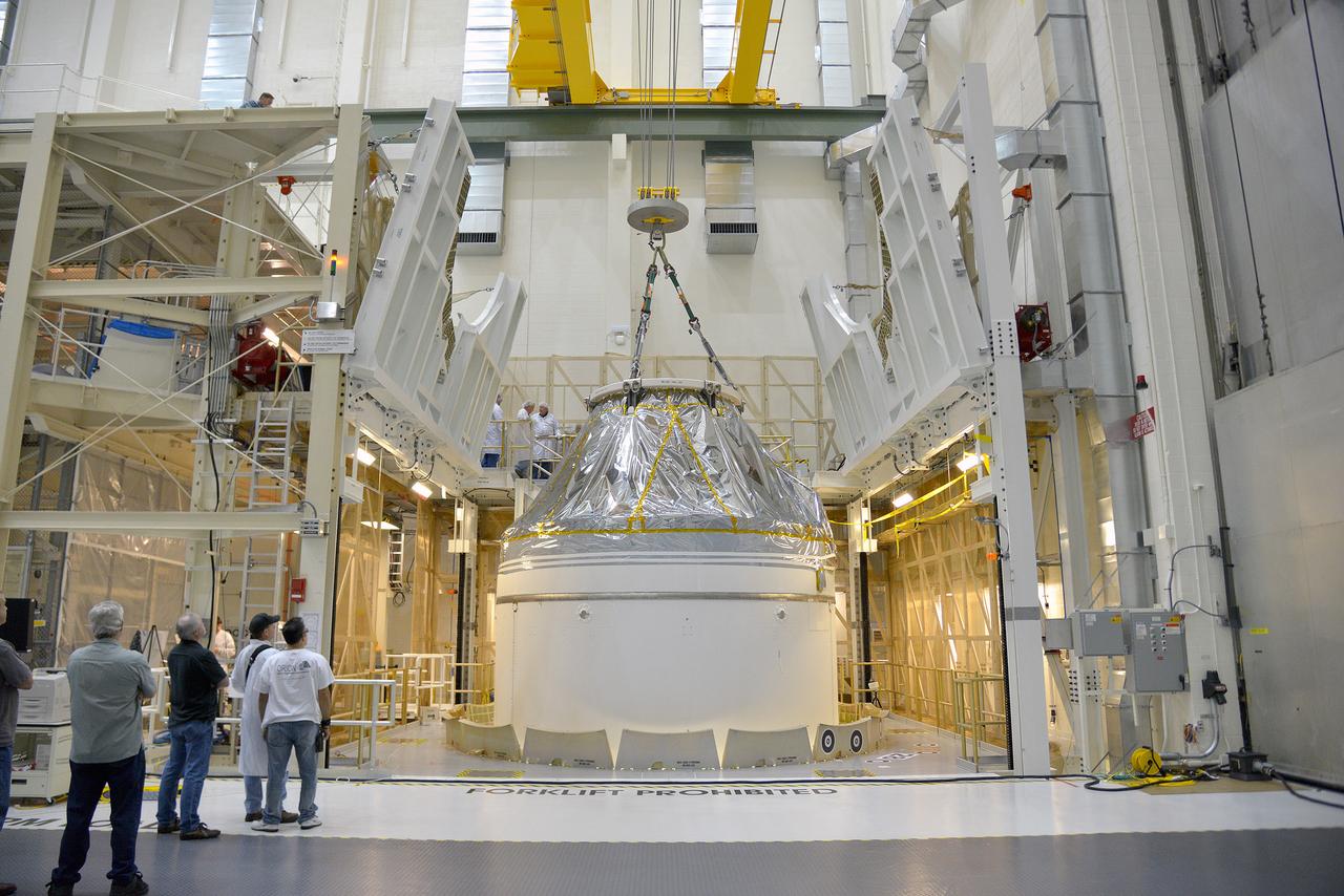
Technicians and engineers put finishing touches on the Orion Exploration Flight Test-1 (EFT-1) crew module and service module stack in the Operations and Checkout (O&C) Building at Kennedy Space Center on Sept. 7, 2014. Part of Batch image transfer from Flickr.
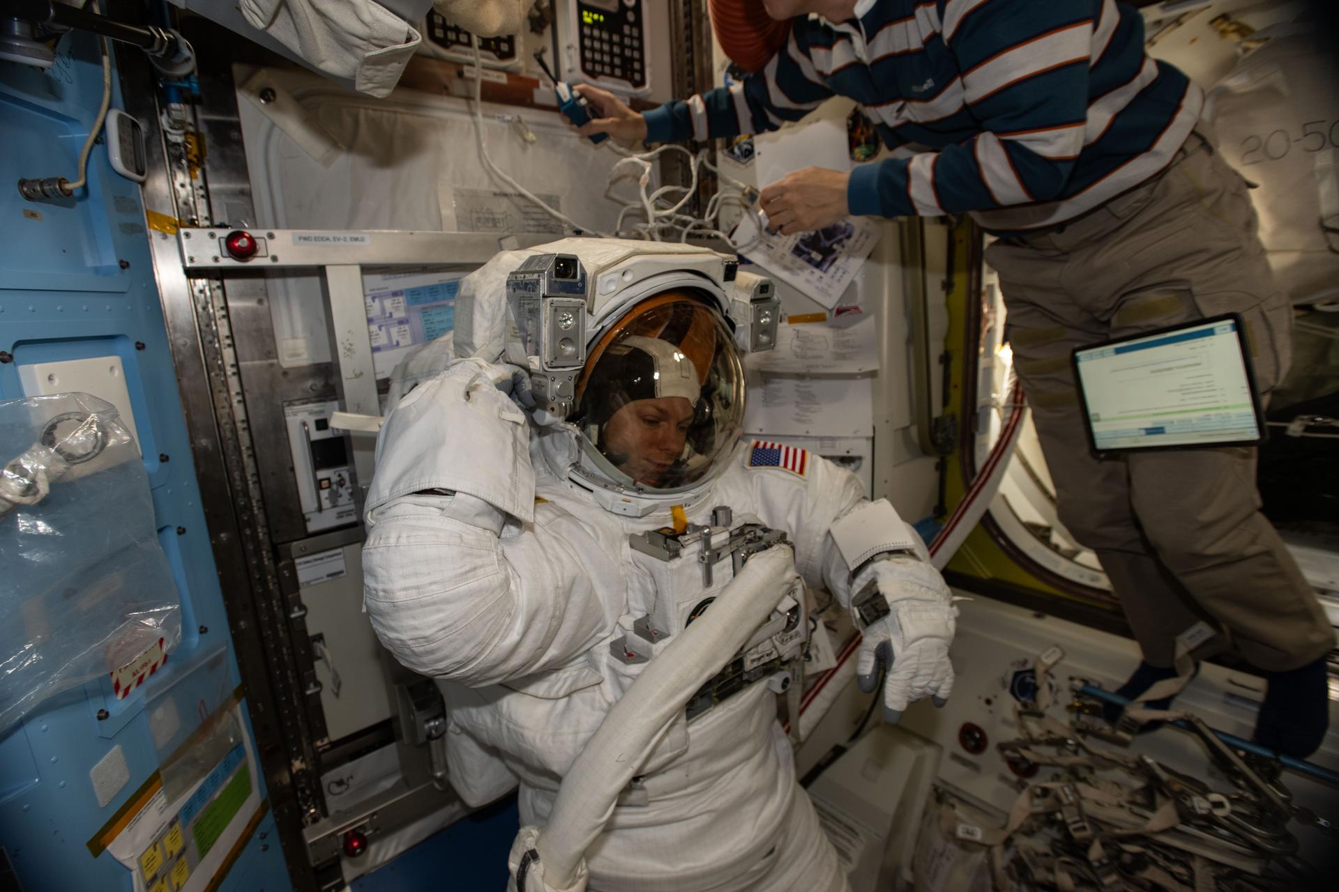
iss074e0007219 (Dec. 30,2025) --- NASA astronaut and Expedition 74 Flight Engineer Zena Cardman is pictured in her pressurized spacesuit, checking its communication and power systems ahead of a spacewalk planned for Thursday, Jan. 8, 2025. At upper right, JAXA (Japan Aerospace Exploration Agency) astronaut and Flight Engineer Kimiya Yui assists Cardman as she tests the operations of her spacesuit inside the International Space Station’s Quest airlock.

L59-3896 Engineers W. N. Gardner and C.A. Brown, Jr., check operations as Trailblazer 1b is readied for Flight, June 4, 1959. Photograph published in A New Dimension Wallops Island Flight Test Range: The First Fifteen Years by Joseph Shortal. A NASA publication, page 675. D58-3001 Model. Engineers W. N. Gardner and C.A. Brown
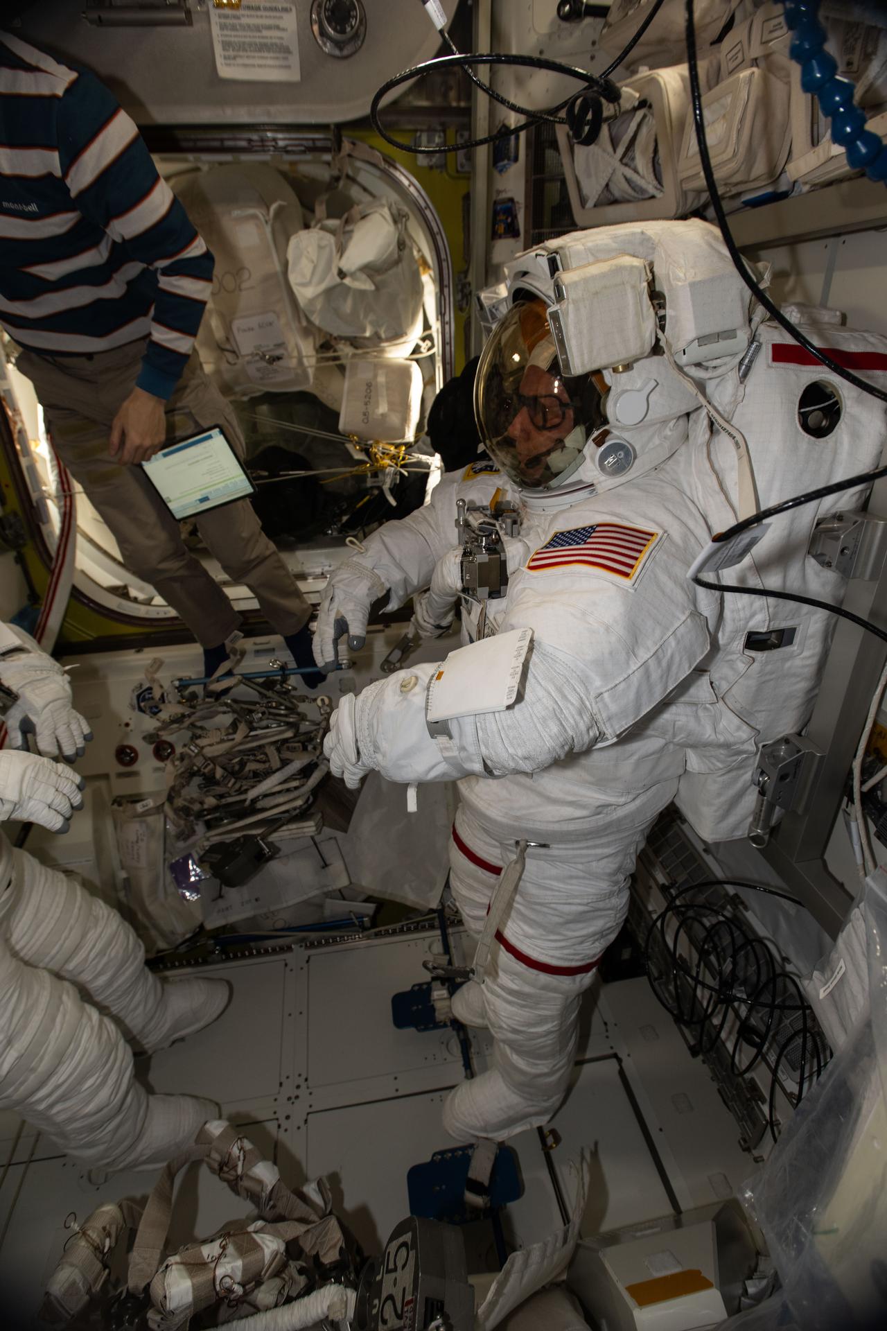
iss074e0007218 (Dec. 30,2025) --- NASA astronaut and Expedition 74 Commander Mike Fincke is pictured in his pressurized spacesuit, checking its communication and power systems ahead of a spacewalk planned for Thursday, Jan. 8, 2025. Partially obscured at left, JAXA (Japan Aerospace Exploration Agency) astronaut and Flight Engineer Kimiya Yui assists NASA Flight Engineer Zena Cardman as she tests the operations of her spacesuit inside the International Space Station’s Quest airlock.
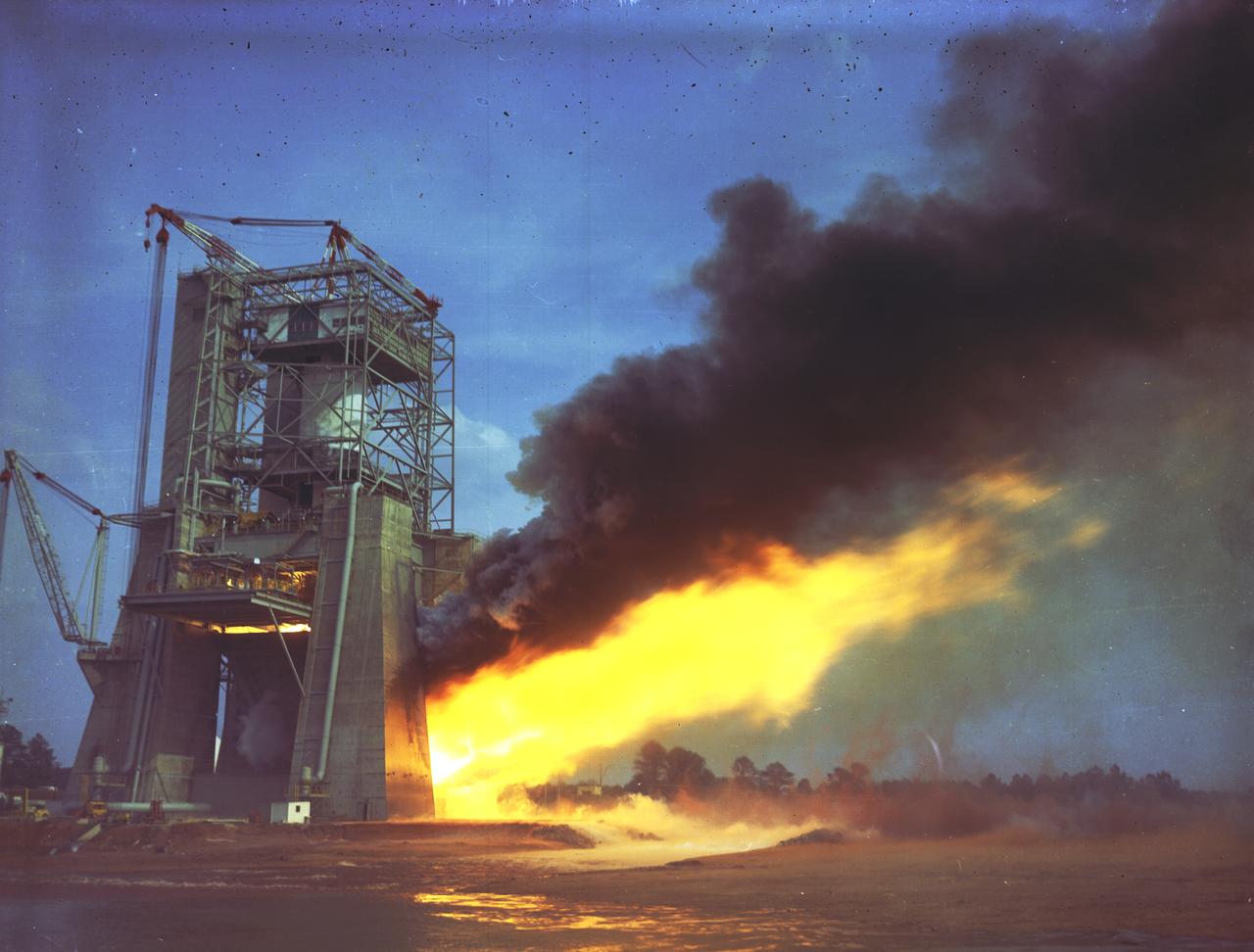
The Saturn V first stages were test fired at the Mississippi Test Facility and at the Marshall Space Flight Center (MSFC). Five F-1 engines powered the first stage, each developing 1.5 million pounds of thrust. The first stage, known as the S-IC stage, burned over 15 tons of propellant per second during its 2.5 minutes of operation to take the vehicle to a height of about 36 miles and to a speed of about 6,000 miles per hour. The stage was 138 feet long and 33 feet in diameter. This photograph shows the test firing of an F-1 engine at the MSFC's S-IC Static Test Firing Facility.
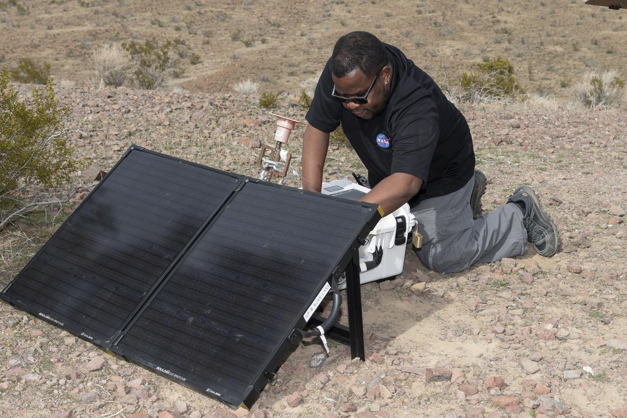
Aerospace engineer Larry Cliatt, Quesst Phase 2 Sub-Project Manager abd technical lead for the acoustic validation phase of the Quesst mission, sets up a ground recording system in the California desert. The Quesst mission recently completed testing of operations and equipment to be used in recording the sonic thumps of the X-59. The testing was the third phase of Carpet Determination in Entirety Measurements flights, called CarpetDIEM for short. An F-15 and an F-18 from NASA’s Armstrong Flight Research Center created sonic booms, both loud and soft, to verify the operations of ground recording systems spread out across 30 miles of open desert.
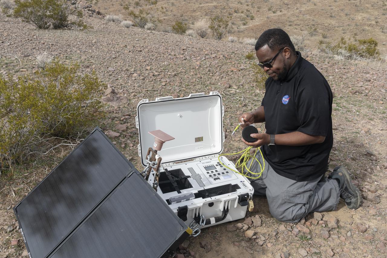
Aerospace engineer Larry Cliatt, Quesst Phase 2 Sub-Project Manager and technical lead for the acoustic validation phase of the Quesst mission, sets up a ground recording system in the California desert. The Quesst mission recently completed testing of operations and equipment to be used in recording the sonic thumps of the X-59. The testing was the third phase of Carpet Determination in Entirety Measurements flights, called CarpetDIEM for short. An F-15 and an F-18 from NASA’s Armstrong Flight Research Center created sonic booms, both loud and soft, to verify the operations of ground recording systems spread out across 30 miles of open desert.

On Feb. 13, 2015, Lockheed Martin engineers remove the heat shield from the Orion vehicle that flew on Exploration Flight Test-1 (EFT-1) in December 2014 in Operations and Checkout Building (O&C) at Kennedy Space Center. The heat shield will be transported to the Marshall Space Flight Center for testing. Part of Batch image transfer from Flickr.
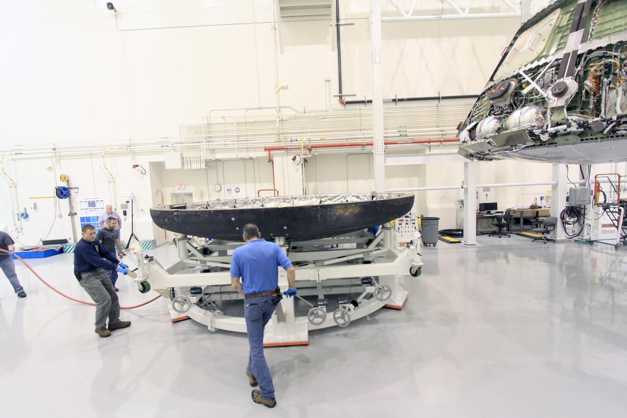
On Feb. 13, 2015, Lockheed Martin engineers remove the heat shield from the Orion vehicle that flew on Exploration Flight Test-1 (EFT-1) in December 2014 in Operations and Checkout Building (O&C) at Kennedy Space Center. The heat shield will be transported to the Marshall Space Flight Center for testing. Part of Batch image transfer from Flickr.
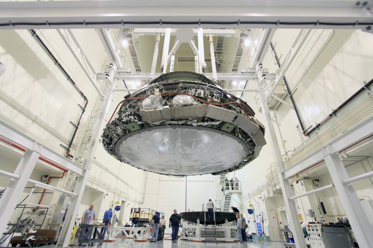
On Feb. 13, 2015, Lockheed Martin engineers remove the heat shield from the Orion vehicle that flew on Exploration Flight Test-1 (EFT-1) in December 2014 in Operations and Checkout Building (O&C) at Kennedy Space Center. The heat shield will be transported to the Marshall Space Flight Center for testing. Part of Batch image transfer from Flickr.
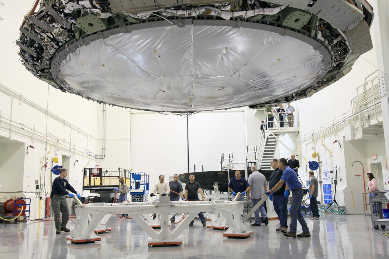
On Feb. 13, 2015, Lockheed Martin engineers remove the heat shield from the Orion vehicle that flew on Exploration Flight Test-1 (EFT-1) in December 2014 in Operations and Checkout Building (O&C) at Kennedy Space Center. The heat shield will be transported to the Marshall Space Flight Center for testing. Part of Batch image transfer from Flickr.
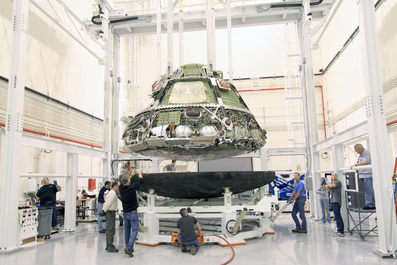
On Feb. 13, 2015, Lockheed Martin engineers remove the heat shield from the Orion vehicle that flew on Exploration Flight Test-1 (EFT-1) in December 2014 in Operations and Checkout Building (O&C) at Kennedy Space Center. The heat shield will be transported to the Marshall Space Flight Center for testing. Part of Batch image transfer from Flickr.

Test of Unmanned Aircraft Systems Traffic Management (UTM) technical capability Level 2 (TCL2) at Reno-Stead Airport, Nevada. During the test, five drones simultaneously crossed paths, separated by altitude. Two drones flew beyond visual line-of-sight and three flew within line-of-sight of their operators. Engineer Joey Mercer reviews flight paths using the UAS traffic management research platform UTM coordinator app to verify and validate flight paths.
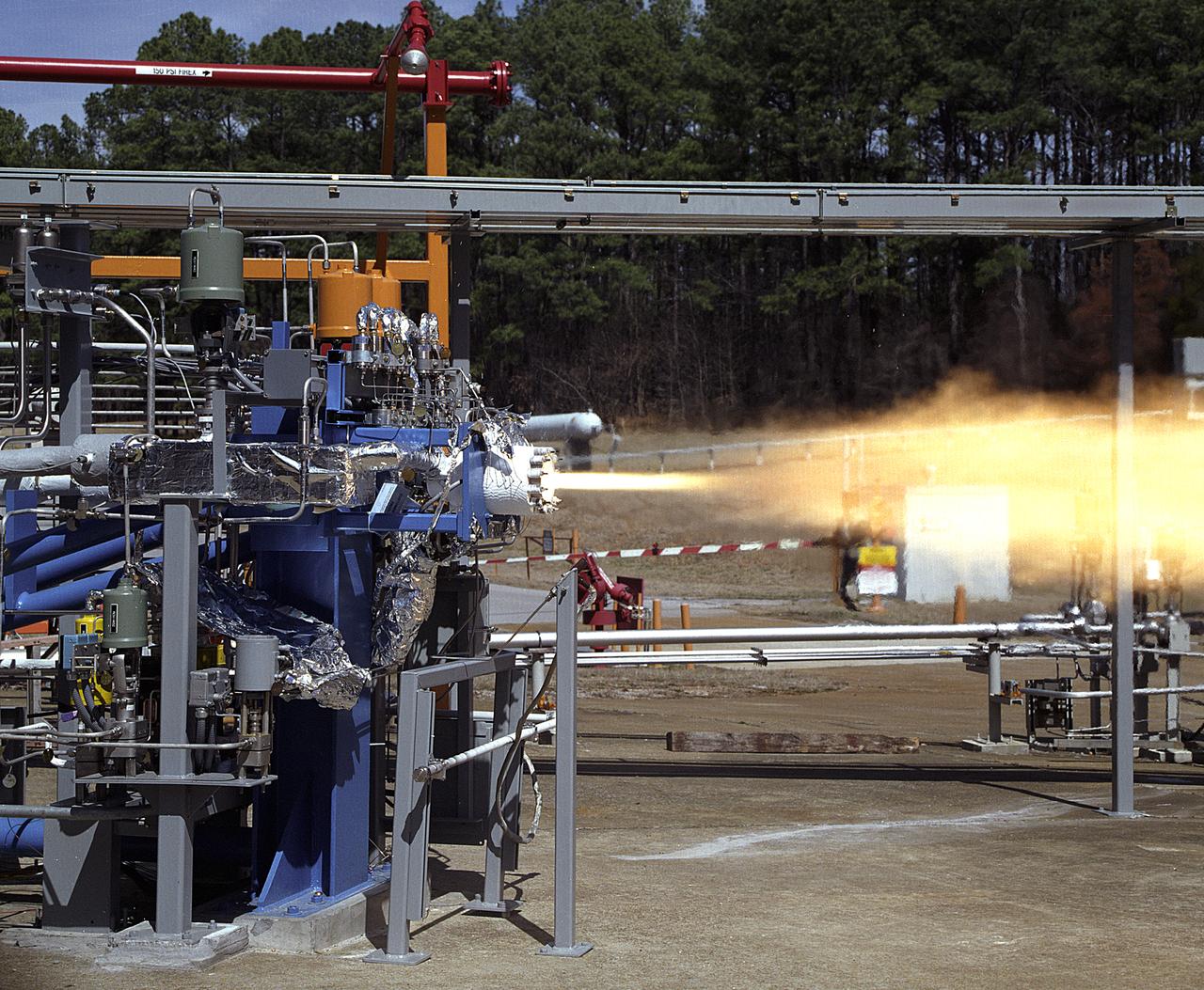
NASA's Marshall Space Flight Center (MSFC) in Huntsville, Alabama, has begun a series of engine tests on the Reaction Control Engine developed by TRW Space and Electronics for NASA's Space Launch Initiative (SLI). SLI is a technology development effort aimed at improving the safety, reliability, and cost effectiveness of space travel for reusable launch vehicles. The engine in this photo, the first engine tested at MSFC that includes SLI technology, was tested for two seconds at a chamber pressure of 185 pounds per square inch absolute (psia). Propellants used were liquid oxygen as an oxidizer and liquid hydrogen as fuel. Designed to maneuver vehicles in orbit, the engine is used as an auxiliary propulsion system for docking, reentry, fine-pointing, and orbit transfer while the vehicle is in orbit. The Reaction Control Engine has two unique features. It uses nontoxic chemicals as propellants, which creates a safer environment with less maintenance and quicker turnaround time between missions, and it operates in dual thrust modes, combining two engine functions into one engine. The engine operates at both 25 and 1,000 pounds of force, reducing overall propulsion weight and allowing vehicles to easily maneuver in space. The force of low level thrust allows the vehicle to fine-point maneuver and dock, while the force of the high level thrust is used for reentry, orbital transfer, and course positioning.
The X-57 operations crew at NASA's Armstrong Flight Research Center prepare for telemetry testing on NASA's first all-electric X-plane, the X-57 Maxwell. Shown here in its first all-electric configuration, known as Mod II, X-57's series of functional tests helps engineers confirm that the vehicle will be ready for taxi and flight tests, and the telemetry testing confirms the ability of the aircraft to transmit location and test data to the ground. X-57 will help set certification standards for emerging electric aircraft markets.
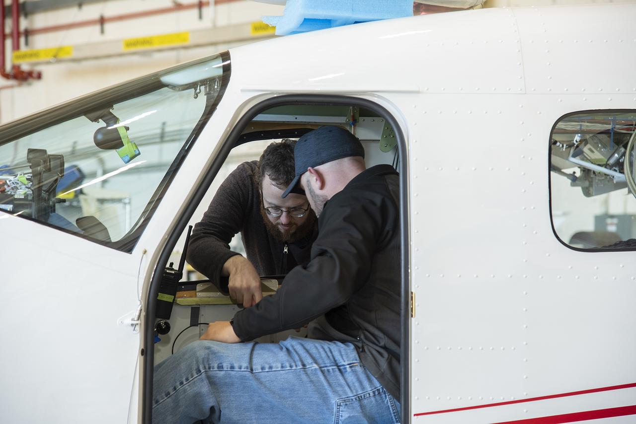
The X-57 operations crew at NASA's Armstrong Flight Research Center prepare for telemetry testing on NASA's first all-electric X-plane, the X-57 Maxwell. Shown here in its first all-electric configuration, known as Mod II, X-57's series of functional tests helps engineers confirm that the vehicle will be ready for taxi and flight tests, and the telemetry testing confirms the ability of the aircraft to transmit location and test data to the ground. X-57 will help set certification standards for emerging electric aircraft markets.
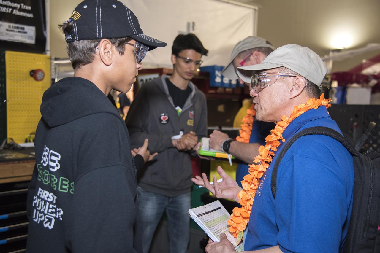
NASA systems engineer, Daniel Eng, right, talks with student participants at the 2019 Aerospace Valley Robotics Competition at the Palmdale Aerospace Academy in Palmdale, California.
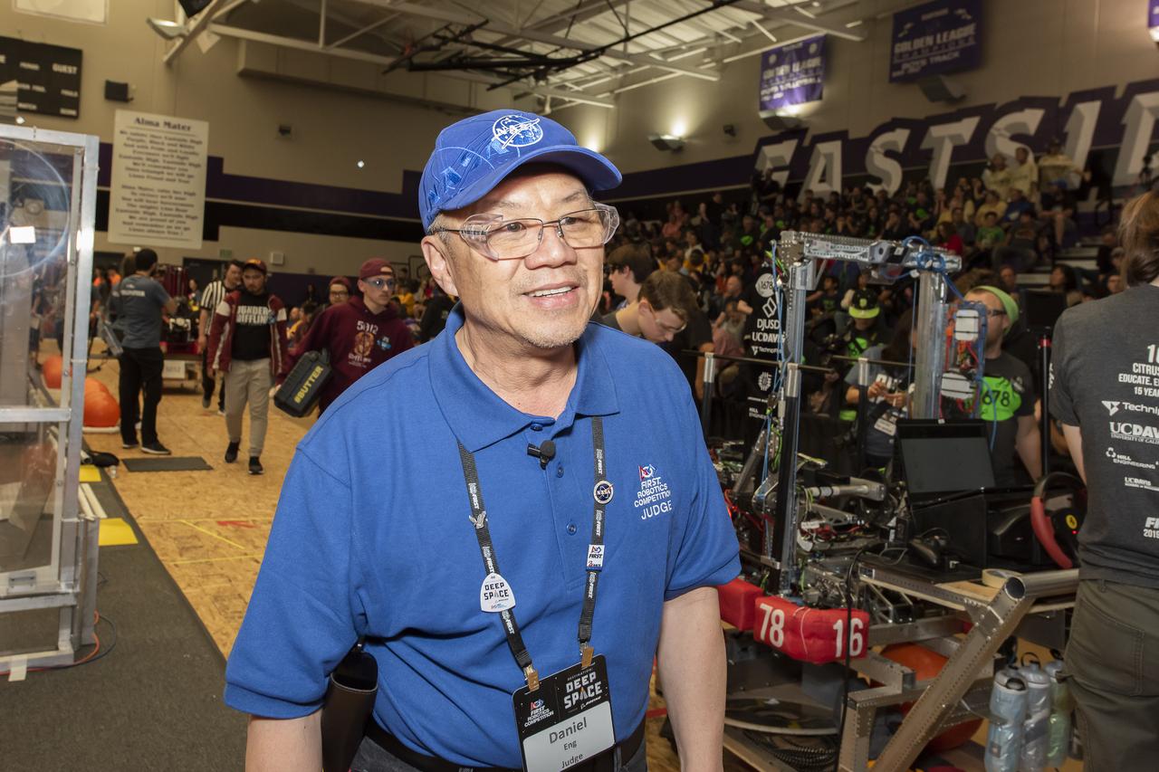
NASA Systems Engineer Daniel Eng serves his second year as a judge for the Aerospace Valley Robotics Competition at the Palmdale Aerospace Academy in Palmdale, California, in 2019.
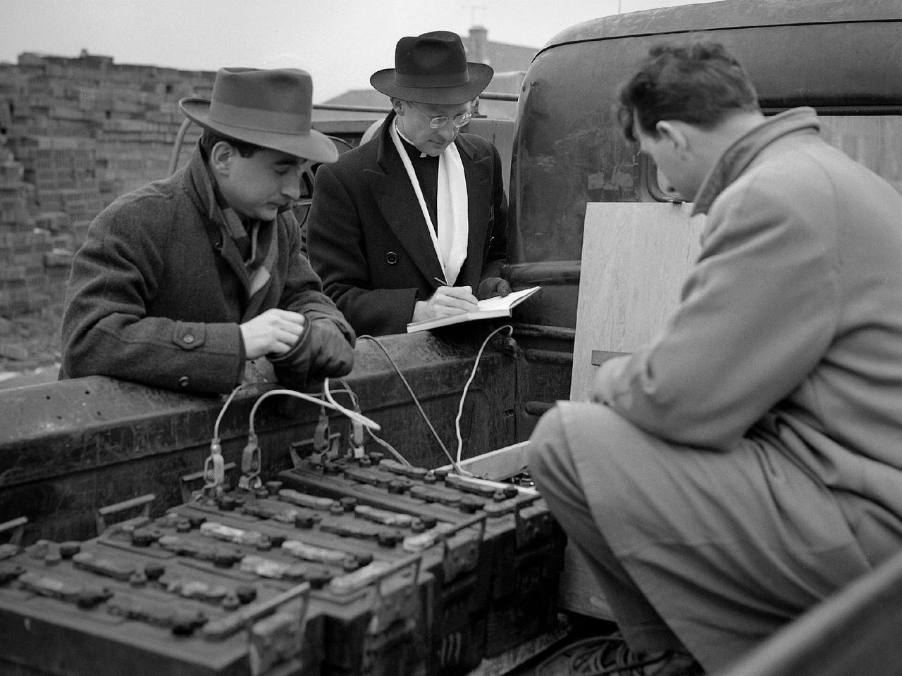
Reverend Henry Birkenhauer and E.F. Carome measure ground vibrations on West 220th Street caused by the operation of the 8- by 6-Foot Supersonic Wind Tunnel at the National Advisory Committee for Aeronautics (NACA) Lewis Flight Propulsion Laboratory. The 8- by 6 was the laboratory’s first large supersonic wind tunnel. It was also the NACA’s most powerful supersonic tunnel, and the NACA’s first facility capable of running an engine at supersonic speeds. The 8- by 6 was originally an open-throat and non-return tunnel. This meant that the supersonic air flow was blown through the test section and out the other end into the atmosphere. Complaints from the local community led to the installation of a muffler at the tunnel exit and the eventual addition of a return leg. Reverend Brikenhauer, a seismologist, and Carome, an electrical technician were brought in from John Carroll University to take vibration measurements during the 8- by 6 tunnel’s first run with a supersonic engine. They found that the majority of the vibrations came from the air and not the ground. The tunnel’s original muffler offered some relief during the facility checkout runs, but it proved inadequate during the operation of an engine in the test section. Tunnel operation was suspended until a new muffler was designed and installed. The NACA researchers, however, were pleased with the tunnel’s operation. They claimed it was the first time a jet engine was operated in an airflow faster than Mach 2.
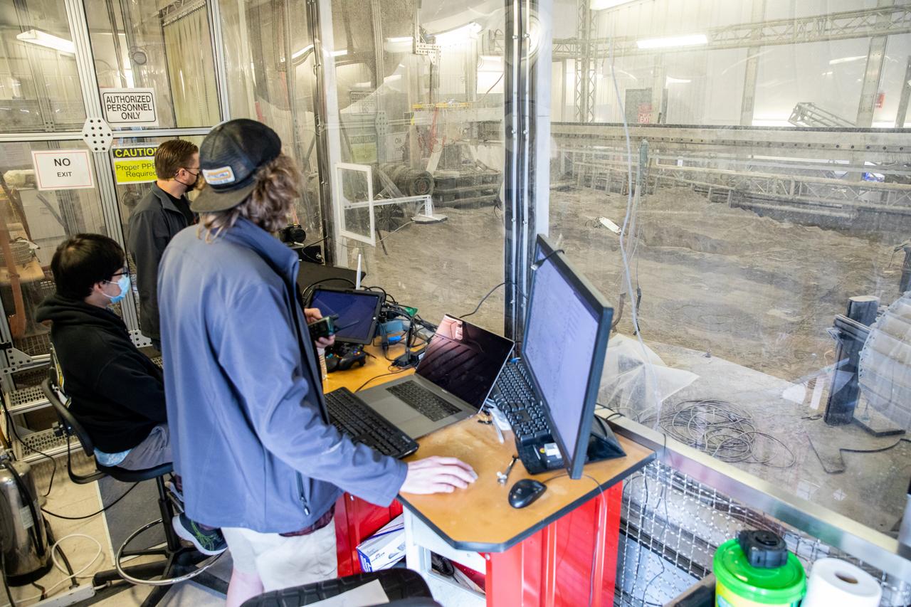
Astrobotic employees Troy Arbuckle, at far left, Planetary Mobility lead mechanical engineer; Takuto Oikawa, mechanical engineer; and Taylor Whitaker, flight software engineer, monitor the progress of the Astrobotic CubeRover during its test run in the Granular Mechanics and Regolith Operations Lab regolith at NASA’s Kennedy Space Center in Florida on Dec. 10, 2020. The regolith bin simulates the mechanical properties of the Moon’s surface. NASA and Astrobotic employees put the CubeRover through a series of more than 150 mobility tests over several days to evaluate and improve wheel design.
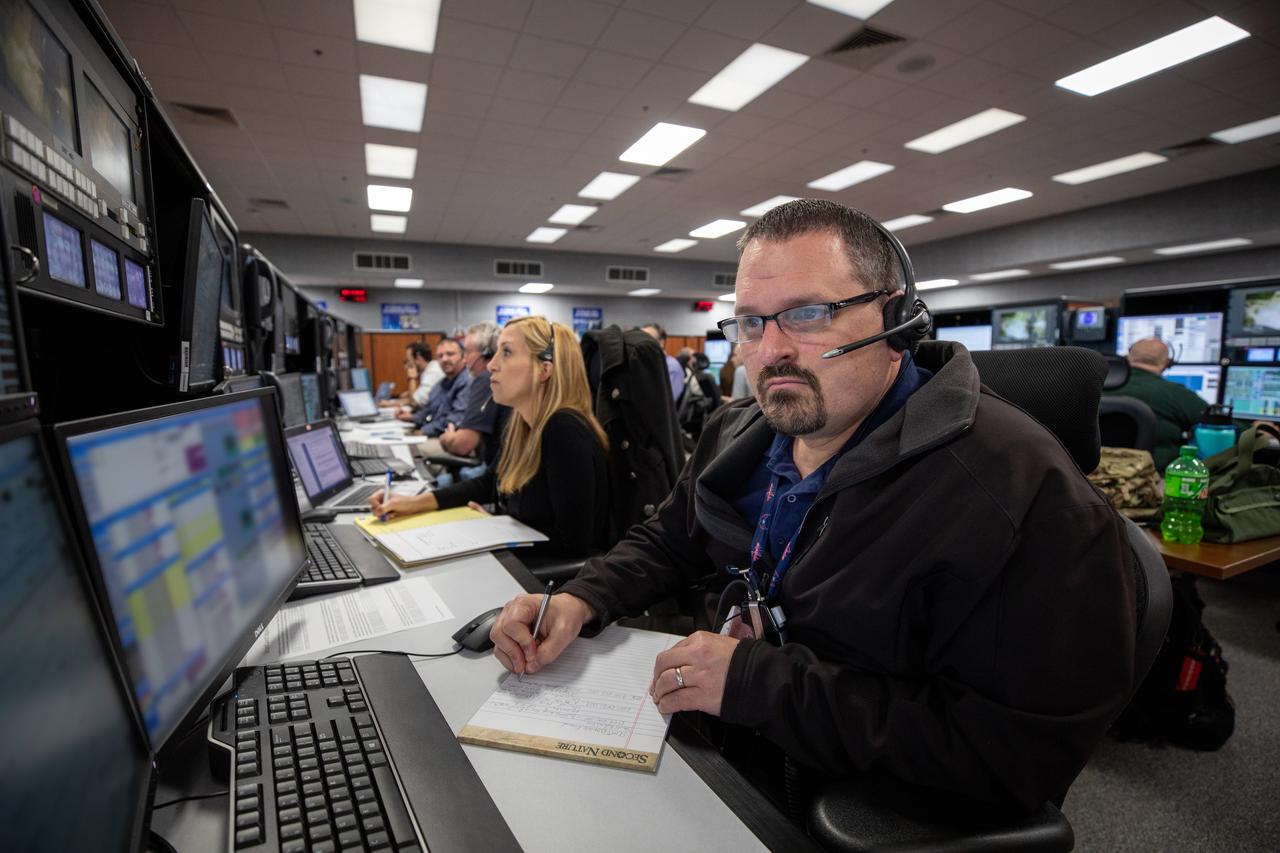
Melissa Batis (left), an operations project engineer, and John Mills, a test project engineer at NASA’s Kennedy Space Center in Florida, participate in a launch countdown simulation inside Firing Room 1 in the Launch Control Center on Feb. 3, 2020. Under the leadership of Artemis I Launch Director Charlie Blackwell-Thompson, a team of nearly 100 engineers from Orion, Space Launch System (SLS) and NASA’s Exploration Ground Systems came together to work through a series of simulated challenges, as well as a final countdown procedure. During these exercises, different issues were introduced to familiarize the team with launch day operations, while providing them with an opportunity to practice how they would handle those issues in real-time. Artemis I will be the first integrated test flight of the Orion spacecraft and SLS rocket – the system that will ultimately land the first woman and the next man on the Moon.
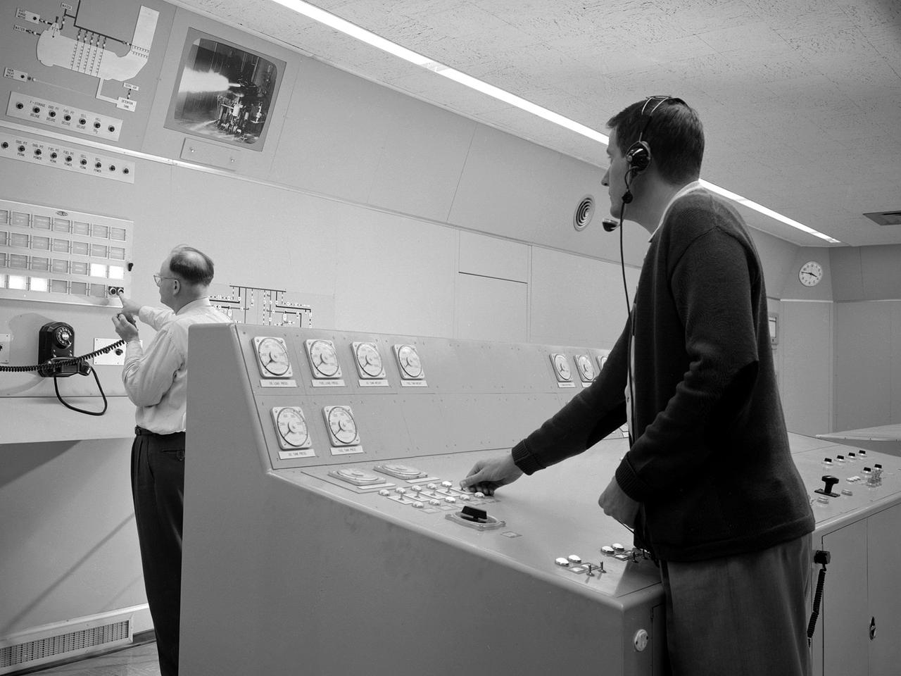
Test engineers monitor an engine firing from the control room of the Rocket Engine Test Facility at the National Advisory Committee for Aeronautics (NACA) Lewis Flight Propulsion Laboratory. The Rocket Engine Test Facility, built in the early 1950s, had a rocket stand designed to evaluate high-energy propellants and rocket engine designs. The facility was used to study numerous different types of rocket engines including the Pratt and Whitney RL-10 engine for the Centaur rocket and Rocketdyne’s F-1 and J-2 engines for the Saturn rockets. The Rocket Engine Test Facility was built in a ravine at the far end of the laboratory because of its use of the dangerous propellants such as liquid hydrogen and liquid fluorine. The control room was located in a building 1,600 feet north of the test stand to protect the engineers running the tests. The main control and instrument consoles were centrally located in the control room and surrounded by boards controlling and monitoring the major valves, pumps, motors, and actuators. A camera system at the test stand allowed the operators to view the tests, but the researchers were reliant on data recording equipment, sensors, and other devices to provide test data. The facility’s control room was upgraded several times over the years. Programmable logic controllers replaced the electro-mechanical control devices. The new controllers were programed to operate the valves and actuators controlling the fuel, oxidant, and ignition sequence according to a predetermined time schedule.
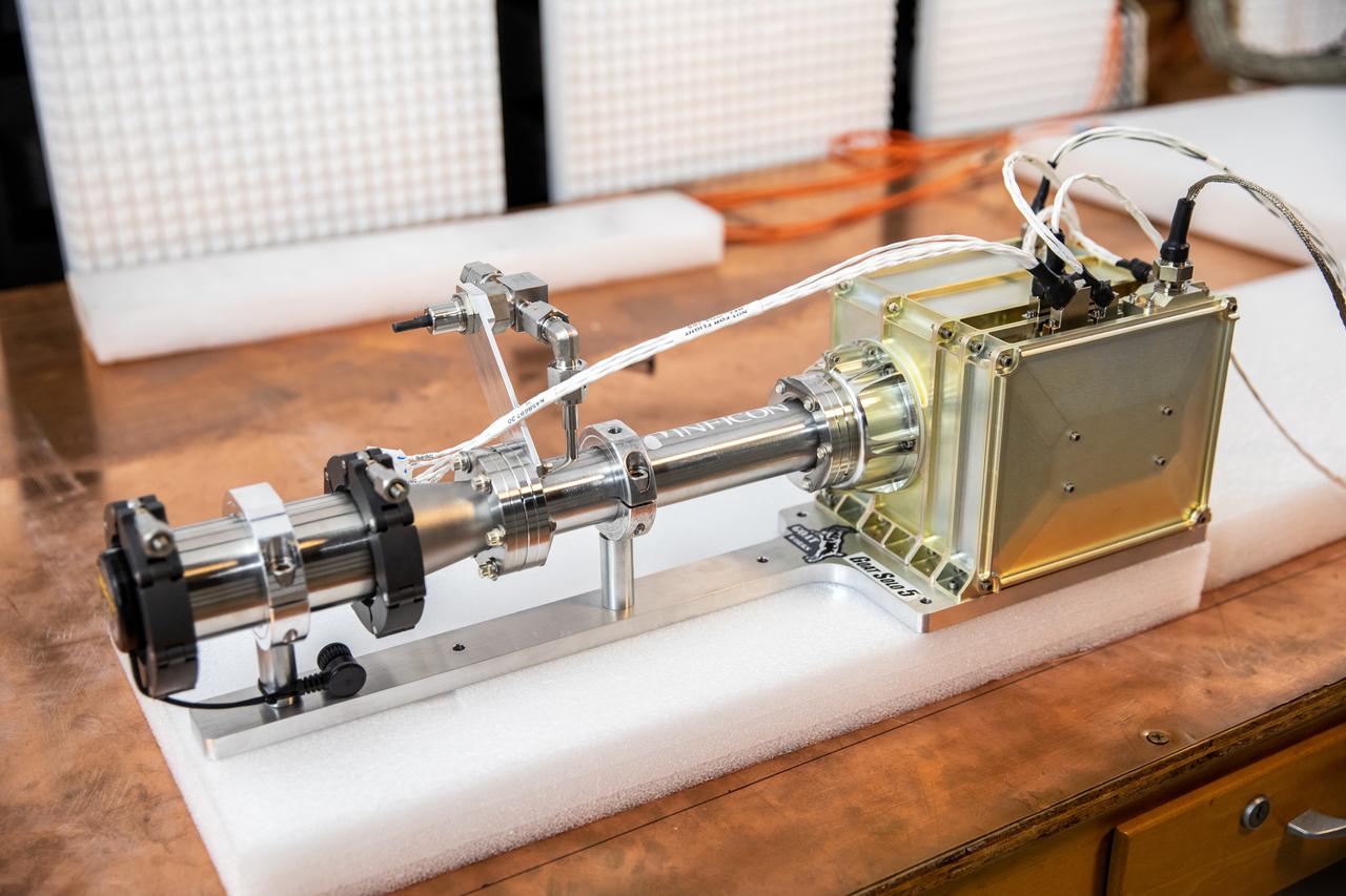
NASA’s Mass Spectrometer Observing Lunar Operations (MSolo) undergoes electromagnetic interference (EMI) testing inside the EMI Laboratory at the agency’s Kennedy Space Center in Florida on Feb. 14, 2022. These tests will verify that MSolo can control the emissions it will produce during its missions and meets EMI susceptibility requirements as part of its preparation to operate in the lunar environment. The third MSolo to go through EMI testing, this is an engineering development unit representative of the flight unit manifested to fly to the Moon’s South Pole as a payload on the agency’s Volatiles Investigating Polar Exploration Rover (VIPER) in 2023. Researchers and engineers are preparing MSolo to launch on four robotic missions as part of NASA’s Commercial Lunar Payload Services (CLPS) – the first of which is slated for later this year. MSolo will help analyze the chemical makeup of landing sites on the Moon, with the later missions also studying water on the lunar surface.
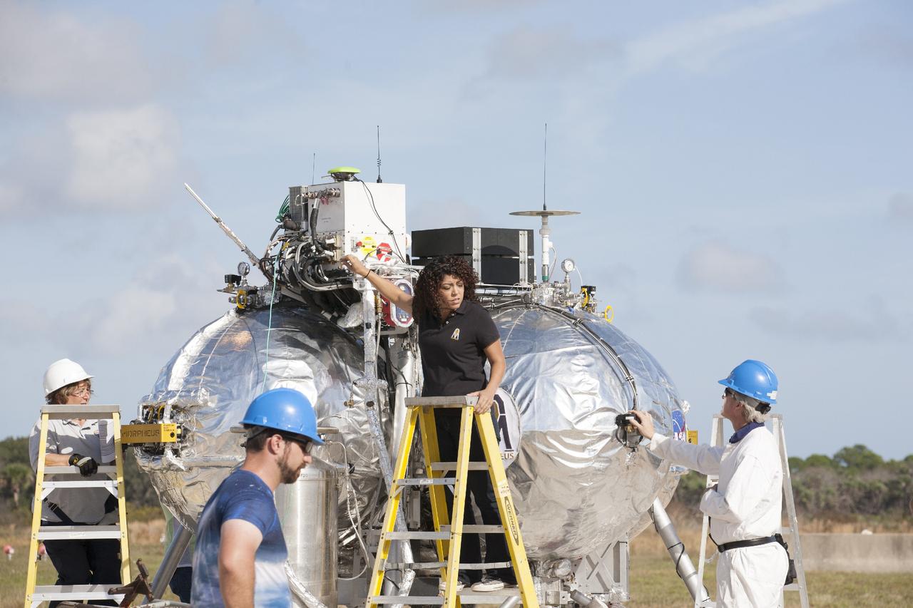
CAPE CANAVERAL, Fla. – Technicians and engineers prepare the Project Morpheus prototype lander for its first free flight test at the north end of the Shuttle Landing Facility at NASA’s Kennedy Space Center in Florida. Testing of the prototype lander was performed at NASA’s Johnson Space Center in Houston in preparation for tethered and free flight testing at Kennedy. Project Morpheus integrates NASA’s automated landing and hazard avoidance technology, or ALHAT, with an engine that runs on liquid oxygen and methane, or green propellants, into a fully-operational lander that could deliver cargo to asteroids and other planetary surfaces. The landing facility will provide the lander with the kind of field necessary for realistic testing, complete with rocks, craters and hazards to avoid. Morpheus’ ALHAT payload allows it to navigate to clear landing sites amidst rocks, craters and other hazards during its descent. Project Morpheus is being managed under the Advanced Exploration Systems, or AES, Division in NASA’s Human Exploration and Operations Mission Directorate. The efforts in AES pioneer new approaches for rapidly developing prototype systems, demonstrating key capabilities and validating operational concepts for future human missions beyond Earth orbit. For more information on Project Morpheus, visit http://morpheuslander.jsc.nasa.gov. Photo credit: NASA/Kim Shiflett
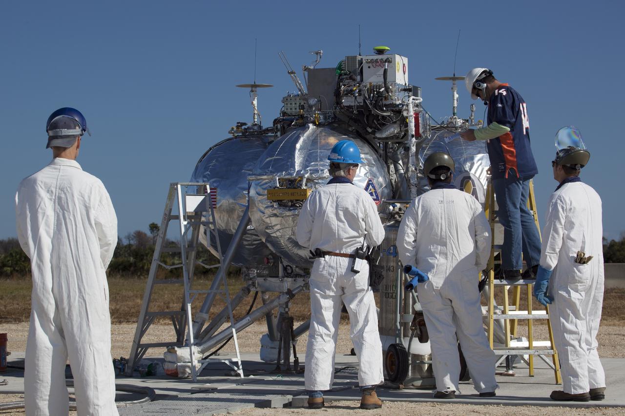
CAPE CANAVERAL, Fla. -- Engineers and technicians prepare the Project Morpheus prototype lander for a second free flight test at the north end of the Shuttle Landing Facility at NASA’s Kennedy Space Center in Florida. Testing of the prototype lander was performed at NASA’s Johnson Space Center in Houston in preparation for tethered and free flight testing at Kennedy. Project Morpheus integrates NASA’s automated landing and hazard avoidance technology, or ALHAT, with an engine that runs on liquid oxygen and methane, or green propellants, into a fully-operational lander that could deliver cargo to other planetary surfaces. The landing facility will provide the lander with the kind of field necessary for realistic testing, complete with rocks, craters and hazards to avoid. Morpheus’ ALHAT payload allows it to navigate to clear landing sites amidst rocks, craters and other hazards during its descent. Project Morpheus is being managed under the Advanced Exploration Systems, or AES, Division in NASA’s Human Exploration and Operations Mission Directorate. The efforts in AES pioneer new approaches for rapidly developing prototype systems, demonstrating key capabilities and validating operational concepts for future human missions beyond Earth orbit. For more information on Project Morpheus, visit http://morpheuslander.jsc.nasa.gov. Photo credit: NASA/Dimitri Gerondidakis
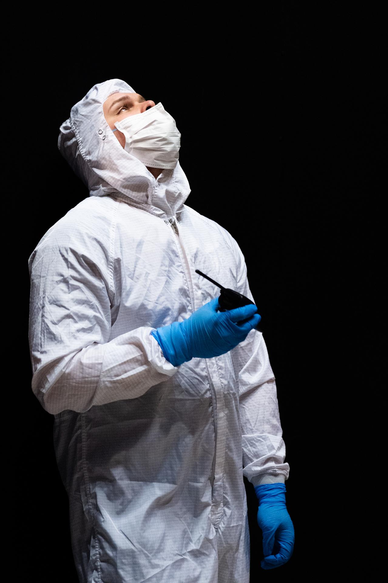
Mechanical engineering and integration technician, Lucas Keim, directs the crane operator from inside the thermal vacuum chamber in support of OSAM-1 environmental testing operations at Goddard Space Flight Center, Greenbelt Md., Nov 30, 2023. This photo has been reviewed by OSAM1 project management and the Export Control Office and is released for public view. NASA/Mike Guinto
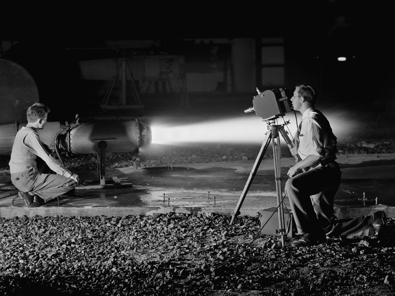
A National Advisory Committee for Aeronautics (NACA) photographer films the test of a ramjet engine at the Lewis Flight Propulsion Laboratory. The laboratory had an arsenal of facilities to test the engines and their components, and immersed itself in the study of turbojet and ramjet engines during the mid-1940s. Combustion, fuel injection, flameouts, and performance at high altitudes were of particular interest to researchers. They devised elaborate schemes to instrument the engines in order to record temperature, pressure, and other data. Many of the tests were also filmed so Lewis researchers could visually review the combustion performance along with the data. The photographer in this image was using high-speed film to document a thrust augmentation study at Lewis’ Jet Static Propulsion Laboratory. The ramjet in this photograph was equipped with a special afterburner as part of a general effort to improve engine performance. Lewis’ Photo Lab was established in 1942. The staff was expanded over the next few years as more test facilities became operational. The Photo Lab’s staff and specialized equipment have been key research tools for decades. They accompany pilots on test flights, use high-speed cameras to capture fleeting processes like combustion, and work with technology, such as the Schlieren camera, to capture supersonic aerodynamics. In addition, the group has documented construction projects, performed publicity work, created images for reports, and photographed data recording equipment.
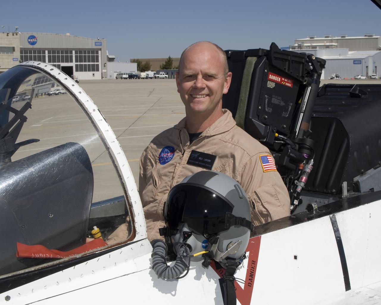
Nils Larson is a research pilot in the Flight Crew Branch of NASA's Dryden Flight Research Center, Edwards, Calif. Larson joined NASA in February 2007 and will fly the F-15, F-18, T-38 and ER-2. Prior to joining NASA, Larson was on active duty with the U.S. Air Force. He has accumulated more that 4,900 hours of military and civilian flight experience in more than 70 fixed and rotary winged aircraft. Larson completed undergraduate pilot training at Williams Air Force Base, Chandler, Ariz., in 1987. He remained at Williams as a T-37 instructor pilot. In 1991, Larson was assigned to Beale Air Force Base, Calif., as a U-2 pilot. He flew 88 operational missions from Korea, Saudi Arabia, the United Kingdom, Panama and other locations. Larson graduated from the U.S. Air Force Test Pilot School at Edwards Air Force Base, Calif., in Class 95A. He became a flight commander and assistant operations officer for the 445th squadron at Edwards. He flew the radar, avionics integration and engine tests in F-15 A-D, the early flights of the glass cockpit T-38C and airworthiness flights of the Coast Guard RU-38. He was selected to serve as an Air Force exchange instructor at the U.S. Naval Test Pilot School, Patuxent River, Md. He taught systems and fixed-wing flight test and flew as an instructor pilot in the F-18, T-2, U-6A Beaver and X-26 Schweizer sailplane. Larson commanded U-2 operations for Warner Robins Air Logistics Center's Detachment 2 located in Palmdale, Calif. In addition to flying the U-2, Larson supervised the aircraft's depot maintenance and flight test. He was the deputy group commander for the 412th Operations Group at Edwards before retiring from active duty in 2007 with the rank of lieutenant colonel. His first experience with NASA was at the Glenn Research Center, Cleveland, where he served a college summer internship working on arcjet engines. Larson is a native of Bethany, W.Va,, and received his commission from the U.S. Air Force Academy in 1986 with a
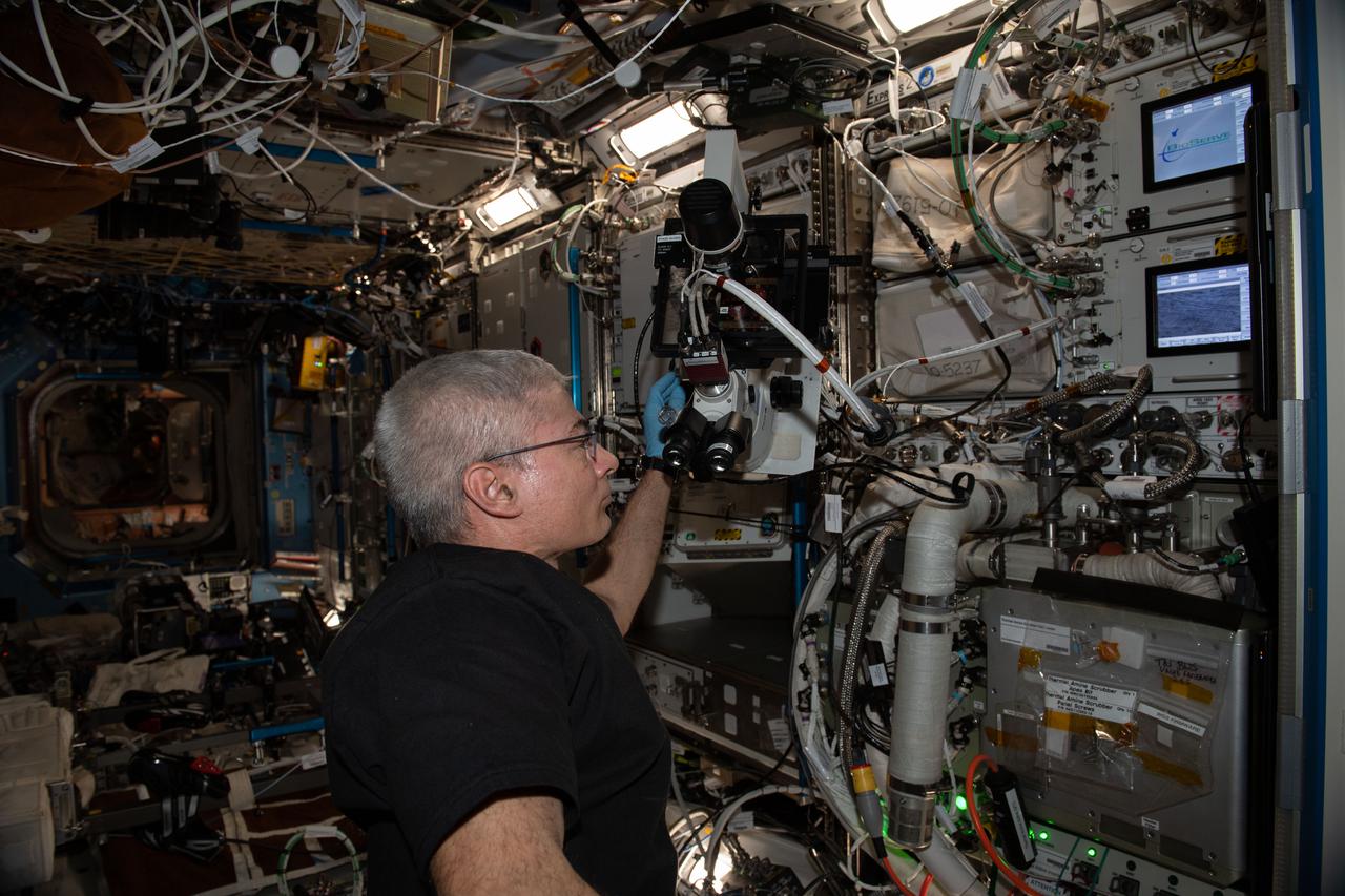
iss065e281836 (Aug. 20, 2021) --- NASA astronaut and Expedition 65 Flight Engineer Mark Vande Hei performs microscopy operations to capture images of the Cardinal Muscle investigation BioCells wells aboard the International Space Station. This study tests whether such engineered tissues cultured in space could provide a model for studying muscle loss and assessing possible therapeutics prior to clinical trials.
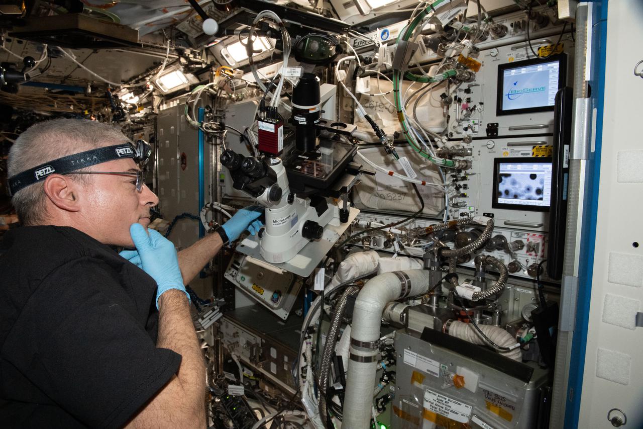
iss065e242415 (Aug. 15, 2021) --- NASA astronaut and Expedition 65 Flight Engineer Mark Vande Hei performs microscopy operations to capture images of the Cardinal Muscle investigation BioCells wells aboard the International Space Station. This study tests whether such engineered tissues cultured in space could provide a model for studying muscle loss and assessing possible therapeutics prior to clinical trials.
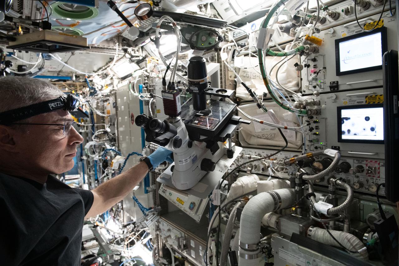
iss065e242412 (Aug. 15, 2021) --- NASA astronaut and Expedition 65 Flight Engineer Mark Vande Hei performs microscopy operations to capture images of the Cardinal Muscle investigation BioCells wells aboard the International Space Station. This study tests whether such engineered tissues cultured in space could provide a model for studying muscle loss and assessing possible therapeutics prior to clinical trials.
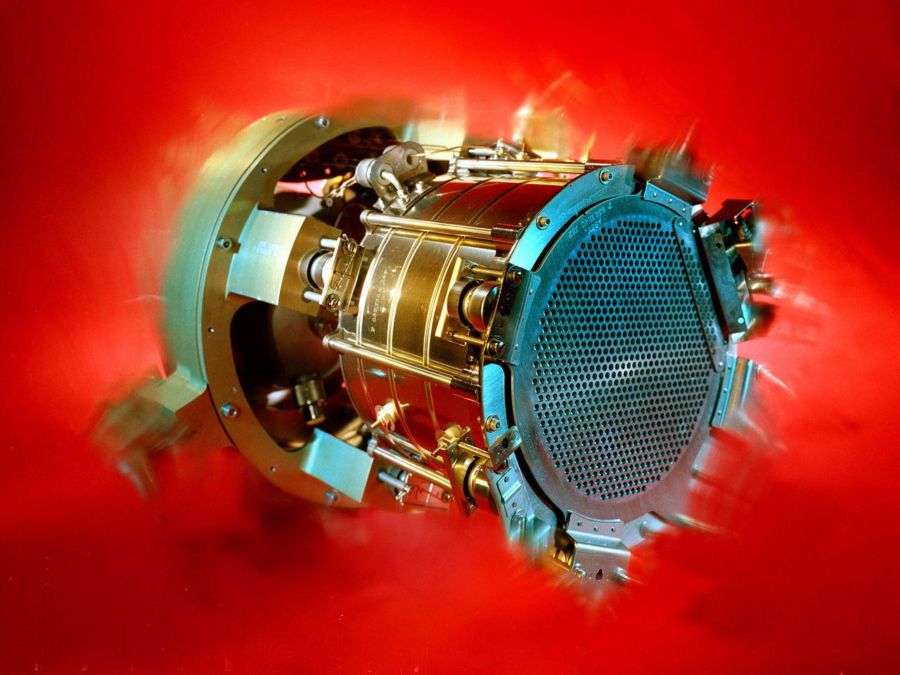
Researchers at the Lewis Research Center had been studying different methods of electric rocket propulsion since the mid-1950s. Harold Kaufman created the first successful engine, the electron bombardment ion engine, in the early 1960s. Over the ensuing decades Lewis researchers continued to advance the original ion thruster concept. A Space Electric Rocket Test (SERT) spacecraft was launched in June 1964 to test Kaufman’s engine in space. SERT I had one cesium engine and one mercury engine. The suborbital flight was only 50 minutes in duration but proved that the ion engine could operate in space. This was followed in 1966 by the even more successful SERT II, which operated on and off for over ten years. Lewis continued studying increasingly more powerful ion thrusters. These electric engines created and accelerated small particles of propellant material to high exhaust velocities. Electric engines have a very small amount of thrust and are therefore not capable of lifting a spaceship from the surface of the Earth. Once lofted into orbit, however, electric engines are can produce small, continuous streams of thrust for several years.
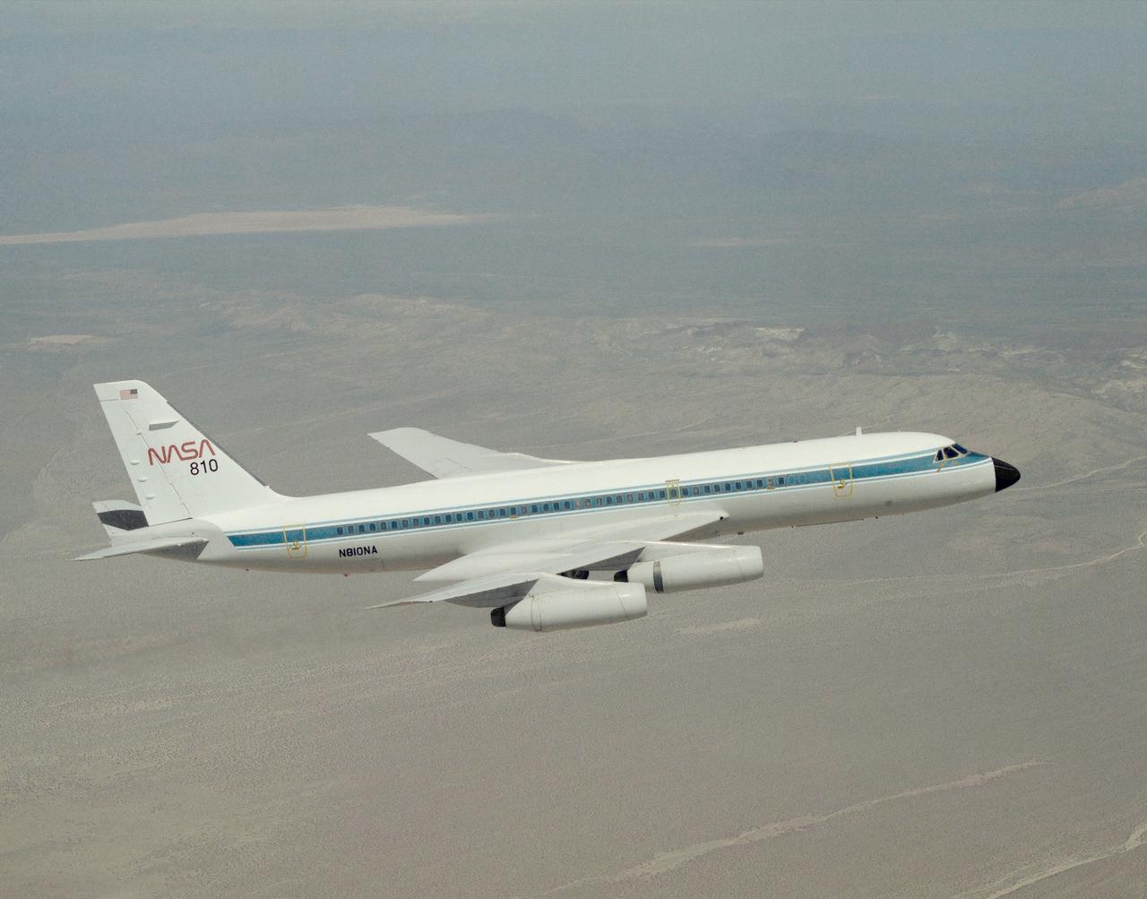
A NASA CV-990, modified as a Landing Systems Research Aircraft (LSRA), in flight over NASA's Dryden Flight Research Center, Edwards, California, for a test of the space shuttle landing gear system. The space shuttle landing gear test unit, operated by a high-pressure hydraulic system, allowed engineers to assess and document the performance of space shuttle main and nose landing gear systems, tires and wheel assemblies, plus braking and nose wheel steering performance. The series of 155 test missions for the space shuttle program provided extensive data about the life and endurance of the shuttle tire systems and helped raise the shuttle crosswind landing limits at Kennedy.
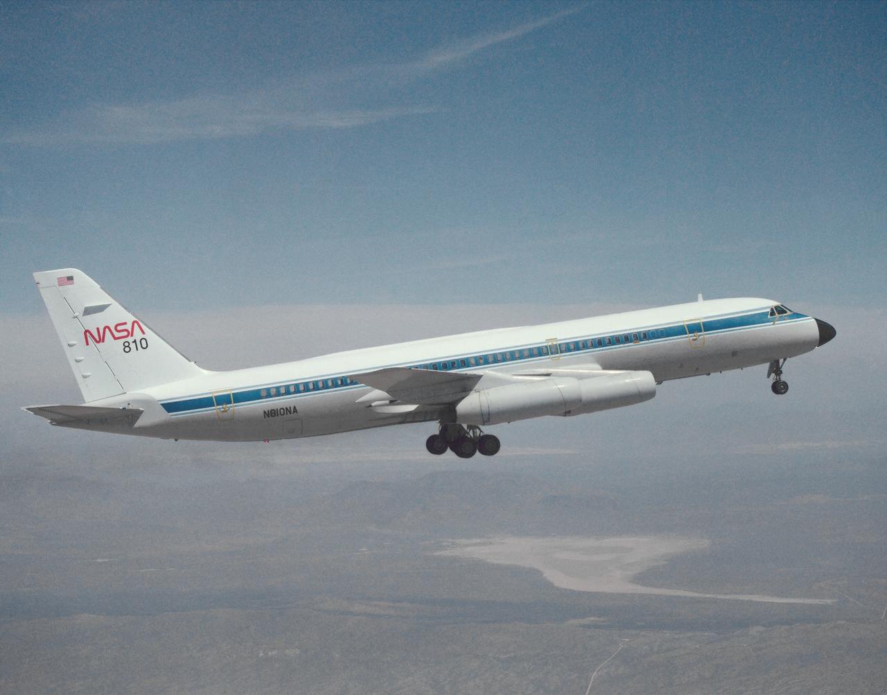
A NASA CV-990, modified as a Landing Systems Research Aircraft (LSRA), in flight over NASA's Dryden Flight Research Center, Edwards, California, for a test of the space shuttle landing gear system. The space shuttle landing gear test unit, operated by a high-pressure hydraulic system, allowed engineers to assess and document the performance of space shuttle main and nose landing gear systems, tires and wheel assemblies, plus braking and nose wheel steering performance. The series of 155 test missions for the space shuttle program provided extensive data about the life and endurance of the shuttle tire systems and helped raise the shuttle crosswind landing limits at Kennedy.