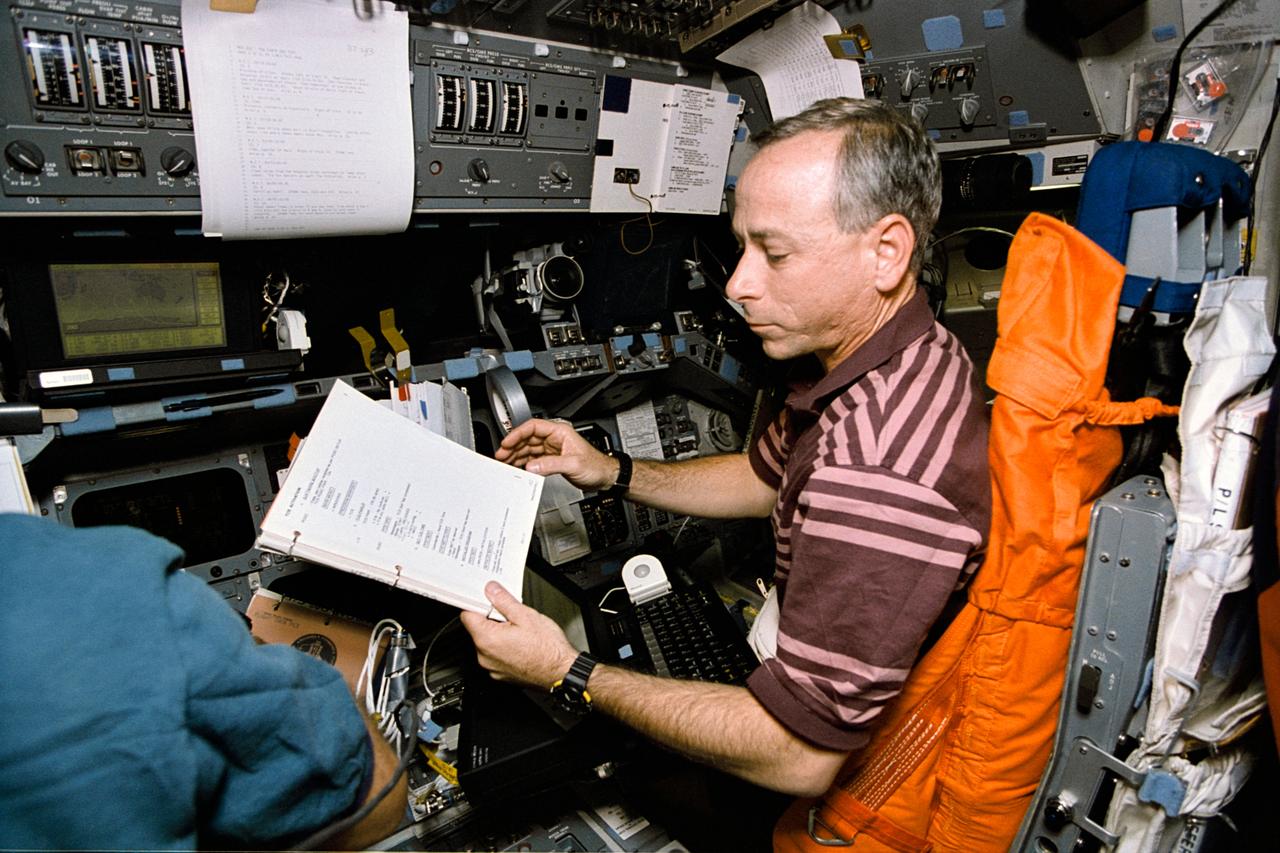
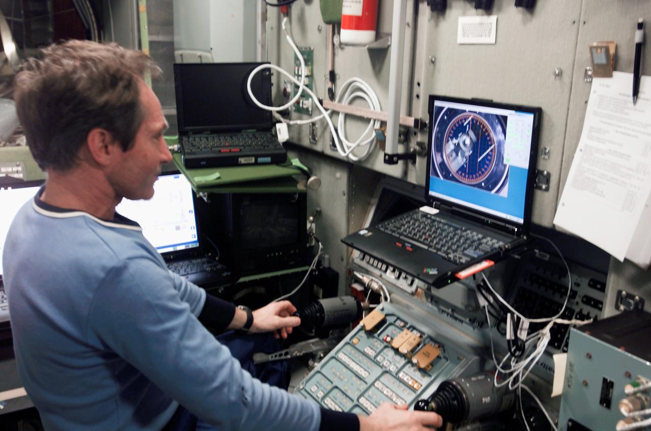
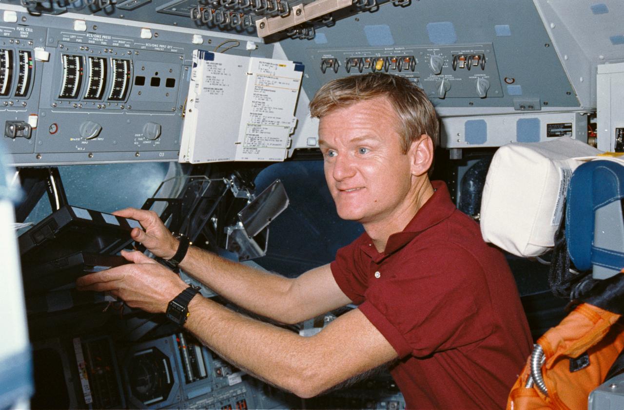
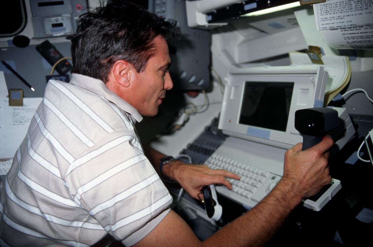
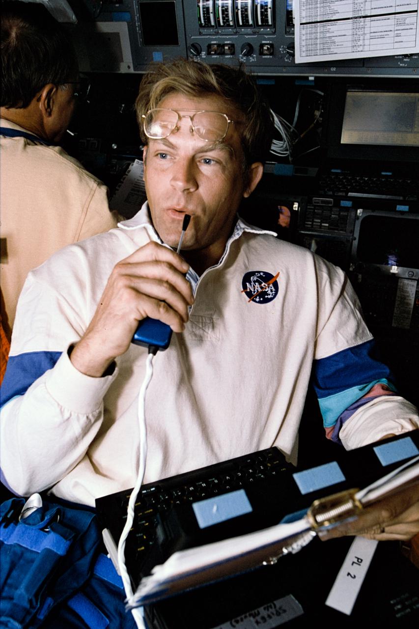
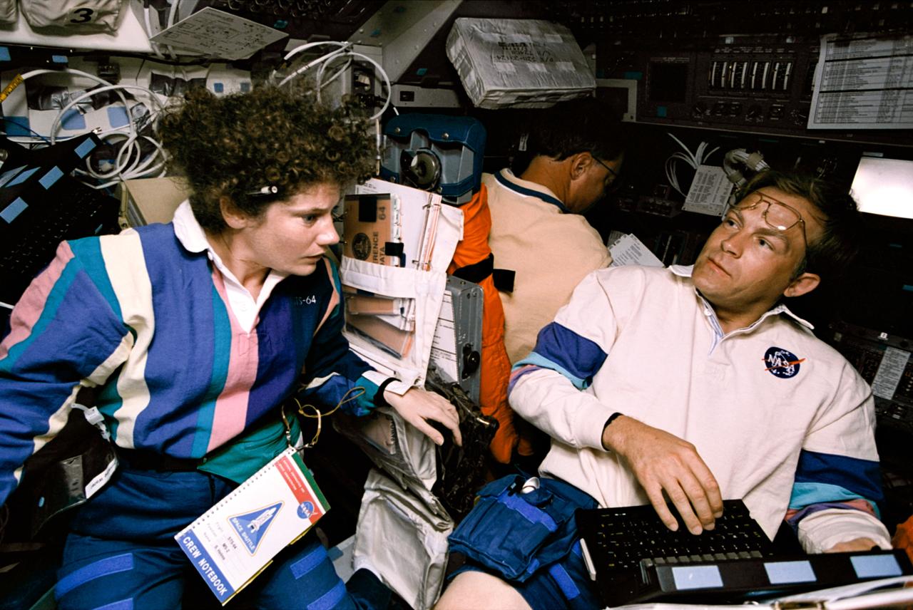
STS064-22-024 (9-20 Sept. 1994) --- With a manual and lap top computer in front of him, astronaut Carl J. Meade, STS-64 mission specialist, supports operations with the Trajectory Control Sensor (TCS) aboard the Earth-orbiting space shuttle Discovery. For this exercise, Meade temporarily mans the pilot's station on the forward flight deck. The TCS is the work of a team of workers at NASA's Johnson Space Center. Data gathered during this flight was expected to prove valuable in designing and developing a sensor for use during the rendezvous and mating phases of orbiter missions to the space station. For this demonstration, the Shuttle Pointed Autonomous Research Tool for Astronomy 201 (SPARTAN 201) was used as the target vehicle during release and retrieval operations. Photo credit: NASA or National Aeronautics and Space Administration

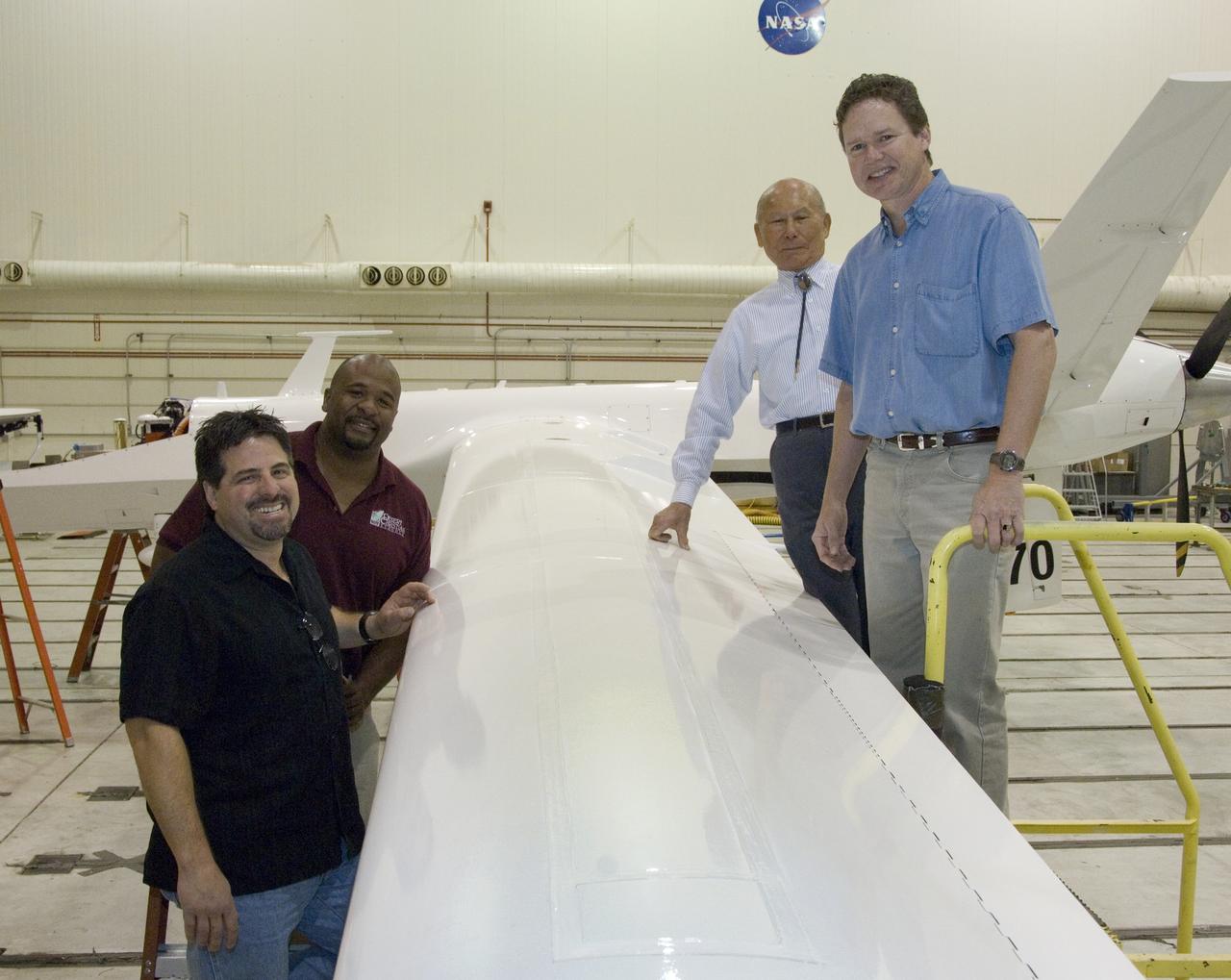
Event: Horizontal Stabilator Install The Low Boom Flight Demonstrator manufacturing team installed the horizontal stabilizers to the aircraft. These are used along with the flight control computers to keep the airplane flying safely and providing the pitch control so that the pilot can fly the missions envisioned for the X-59

Event: Horizontal Stabilator Install The Low Boom Flight Demonstrator manufacturing team installed the horizontal stabilizers to the aircraft. These are used along with the flight control computers to keep the airplane flying safely and providing the pitch control so that the pilot can fly the missions envisioned for the X-59.

Event: Horizontal Stabilator Install The Low Boom Flight Demonstrator manufacturing team installed the horizontal stabilizers to the aircraft. These are used along with the flight control computers to keep the airplane flying safely and providing the pitch control so that the pilot can fly the missions envisioned for the X-59.

Event: Horizontal Stabilator Install The Low Boom Flight Demonstrator manufacturing team installed the horizontal stabilizers to the aircraft. These are used along with the flight control computers to keep the airplane flying safely and providing the pitch control so that the pilot can fly the missions envisioned for the X-59.
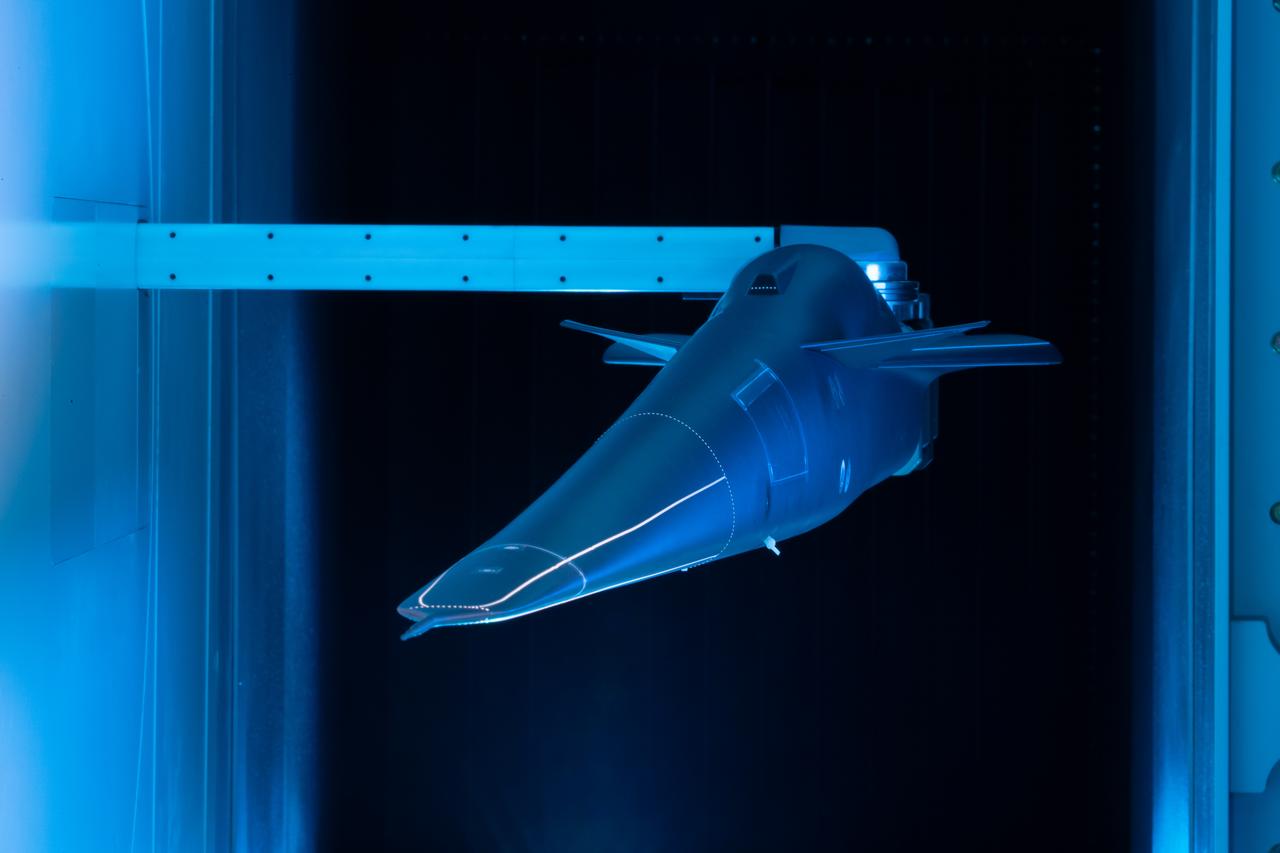
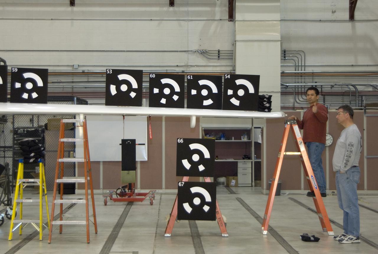
Event: Forebody and Nose - Windtunnel Testing A model of the X-59 forebody is shown in the Lockheed Martin Skunk Works’ wind tunnel in Palmdale, California. These tests gave the team measurements of wind flow angle around the aircraft’s nose and confirmed computer predictions made using computational fluid dynamics (CFD) software tools. The data will be fed into the aircraft flight control system to tell the pilot the aircraft’s altitude, speed and angle. This is part of NASA’s Quesst mission which plans to help enable supersonic air travel over land.
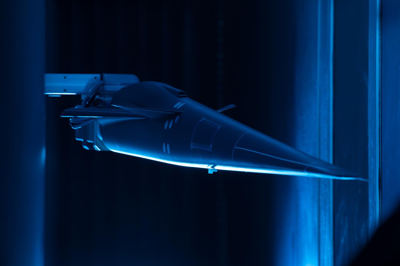
Event: Forebody and Nose - Windtunnel Testing A model of the X-59 forebody is shown in the Lockheed Martin Skunk Works’ wind tunnel in Palmdale, California. These tests gave the team measurements of wind flow angle around the aircraft’s nose and confirmed computer predictions made using computational fluid dynamics (CFD) software tools. The data will be fed into the aircraft flight control system to tell the pilot the aircraft’s altitude, speed and angle. This is part of NASA’s Quesst mission which plans to help enable supersonic air travel over land.
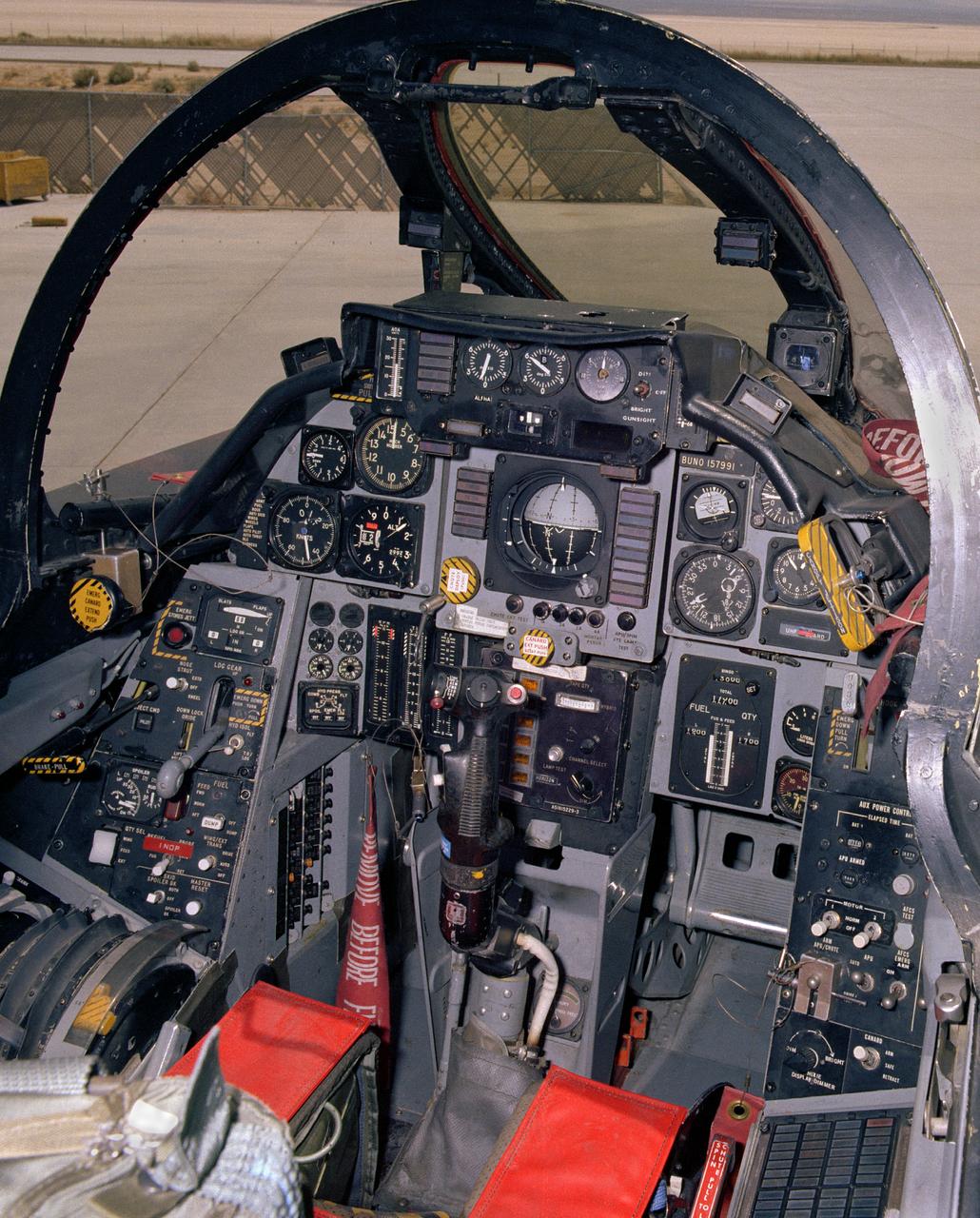
View of the cockpit of NASA's F-14, tail number 991. This aircraft was the first of a series of post-Vietnam fighters, followed by the F-15, F-16, and F-18. They were designed for maneuverability in air-to-air combat. The F-14s had a spin problem that posed problems for its ability to engage successfully in a dogfight, since it tended to depart from controlled flight at the high angles of attack that frequently occur in close-in engagements.
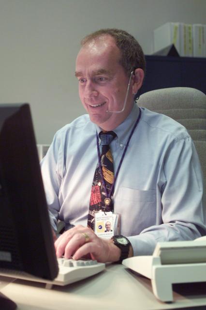
JSC2001-E-21583 (16 July 2001) --- Flight controller James M. Duncan inputs data into his computer at his console in Houston's Mission Control Center (MCC) during the STS-104 mission.
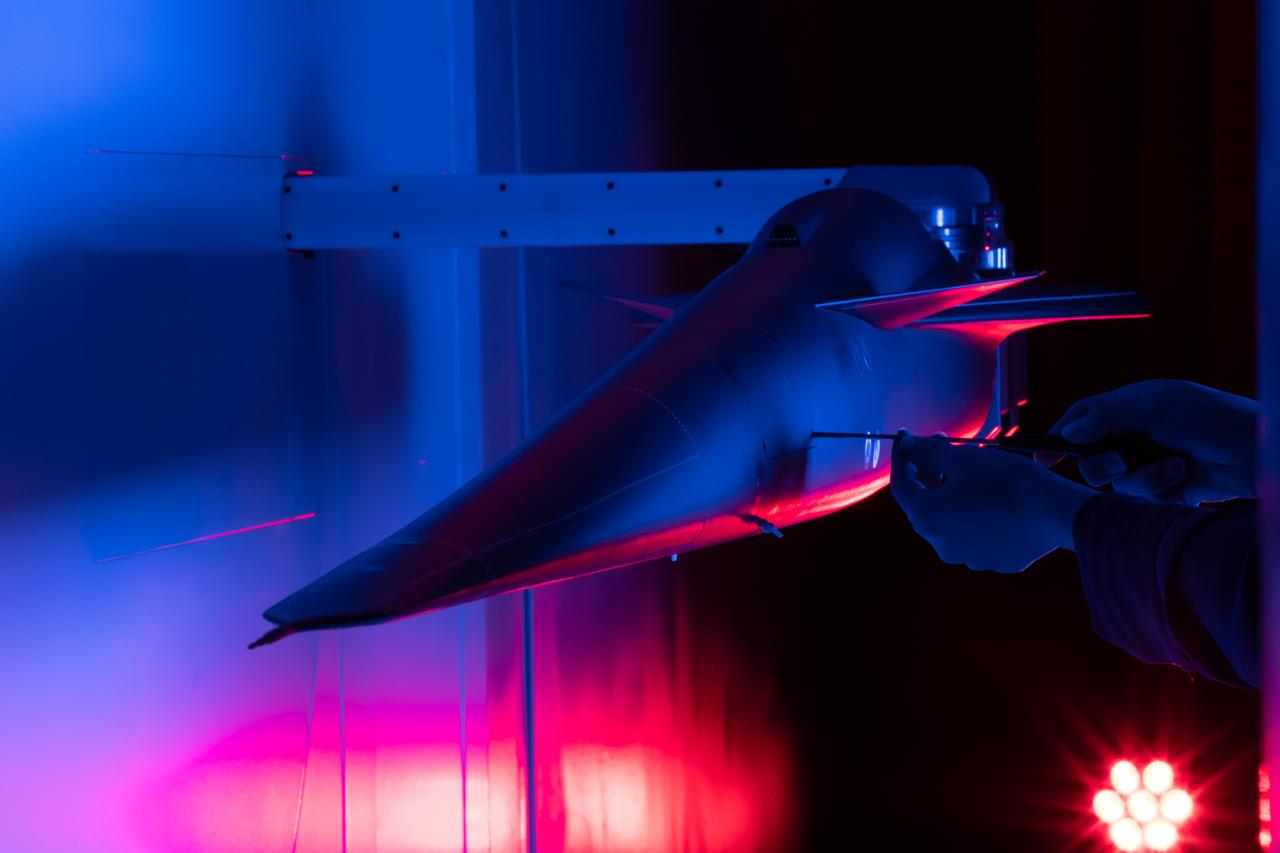
Event: Forebody and Nose - Windtunnel Testing A technician works on the X-59 model during testing in the low-speed wind tunnel at Lockheed Martin Skunk Works in Palmdale, California. These tests gave the team measurements of wind flow angle around the aircraft’s nose and confirmed computer predictions made using computational fluid dynamics (CFD) software tools. The data will be fed into the aircraft flight control system to tell the pilot the aircraft’s altitude, speed, and angle. This is part of NASA’s Quesst mission which plans to help enable supersonic air travel over land.
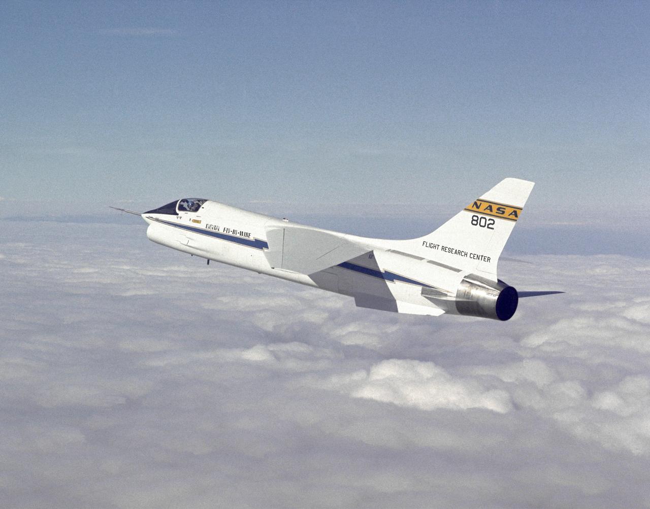
F-8 Digital Fly-By-Wire aircraft in flight. The computer-controlled flight systems pioneered by the F-8 DFBW created a revolution in aircraft design. The F-117A, X-29, X-31, and many other aircraft have relied on computers to make them flyable. Built with inherent instabilities to make them more maneuverable, they would be impossible for human pilots to fly if the computers failed or received incorrect data.
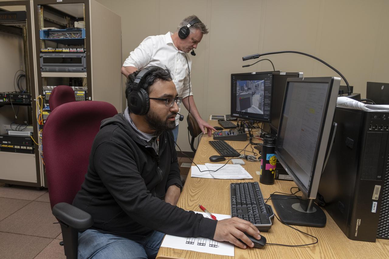
NASA researchers Curt Hanson (background) and Saravanakumaar Ramia (foreground) control the air taxi virtual reality flight simulator from computers during a test at NASA’s Armstrong Flight Research Center in Edwards, California in March 2024.
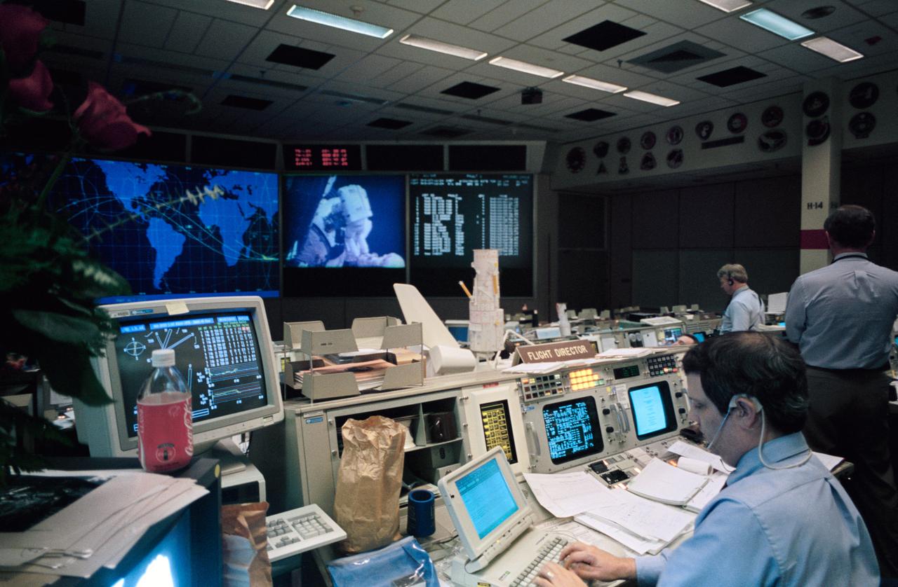
STS061-S-103 (2-13 DEC 1993) --- Flight director Robert E. Castle uses a lap top computer to aid his busy tasks during one of the five space walks performed to service the Hubble Space Telescope (HST) temporarily berthed in the Space Shuttle Endeavour's cargo bay. STS-61 lead flight director Milt Heflin is at right edge of frame.
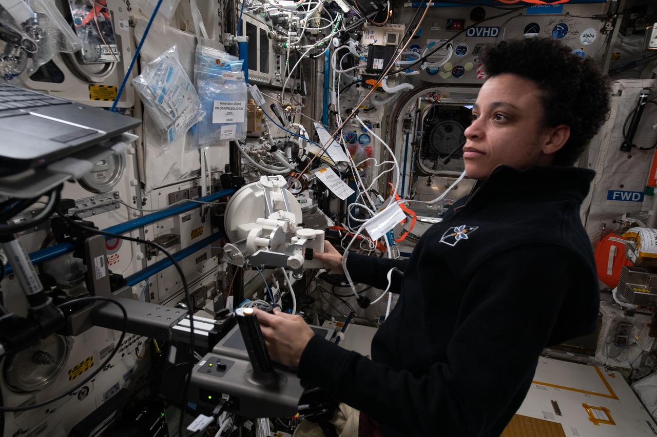
iss067e369288 (Sept. 19, 2022) --- NASA astronaut and Expedition 67 Flight Engineer Jessica Watkins works on the Surface Avatar laptop computer in the Columbus laboratory module to study ways, such as haptic controls, user interfaces, and virtual reality, to command and control surface-bound robots from space.
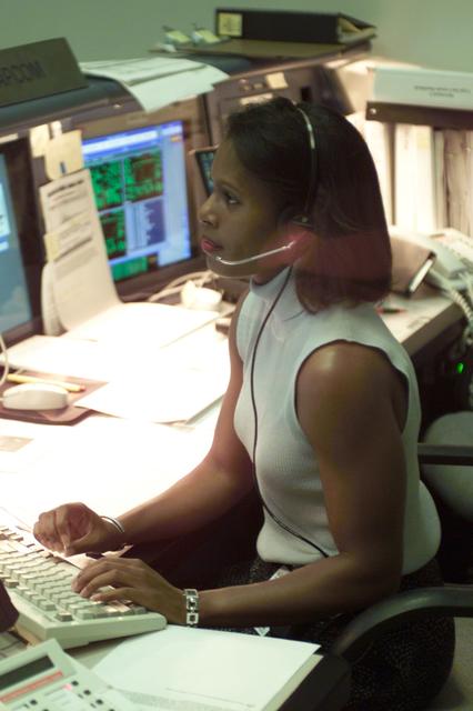
JSC2001-E-25411 (17 August 2001) --- Astronaut Joan E. Higginbotham, ISS spacecraft communicator (CAPCOM), inputs data into her computer at her console in the station flight control room (BFCR) in Houston's Mission Control Center (MCC) during the STS-105 mission.
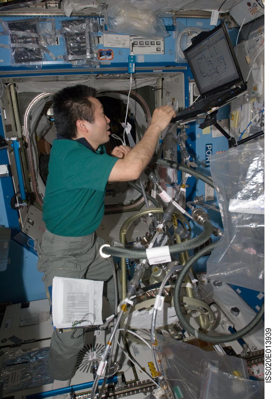
ISS020-E-013939 (23 June 2009) --- Japan Aerospace Exploration Agency (JAXA) astronaut Koichi Wakata, Expedition 20 flight engineer, uses a computer while working with the Fluid Control Pump Assembly (FCPA), which is a part of the Internal Thermal Control System (ITCS) in the Destiny laboratory on the International Space Station.
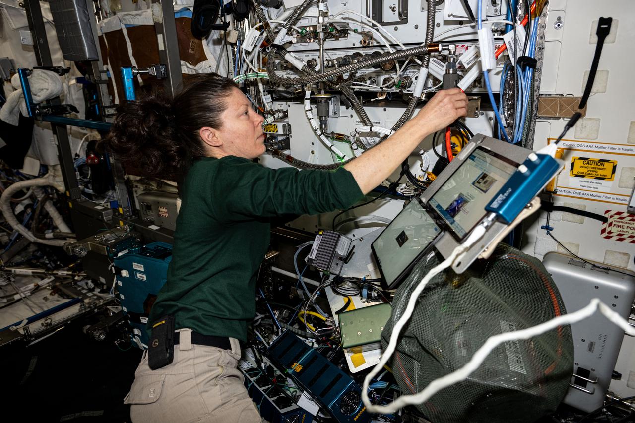
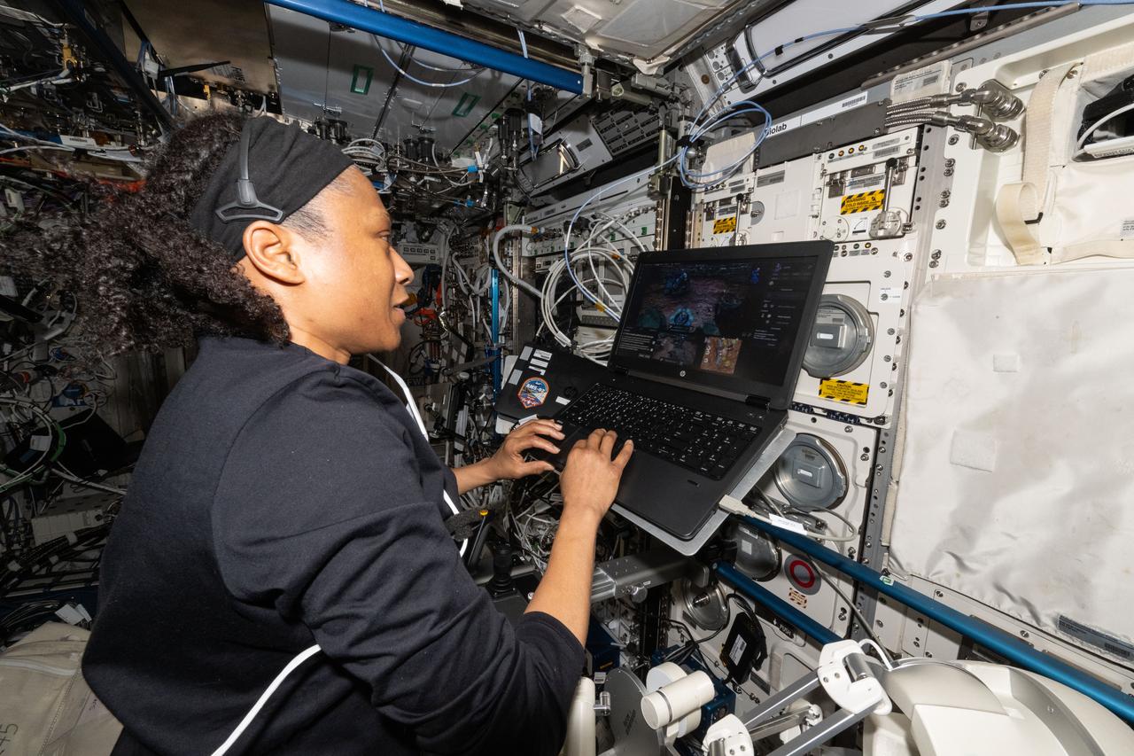
iss071e609375 (Sept. 5, 2024) --- NASA astronaut and Expedition 71 Flight Engineer Tracy C. Dyson tests the configuration of computers that control life support systems aboard the International Space Station's Destiny laboratory module.
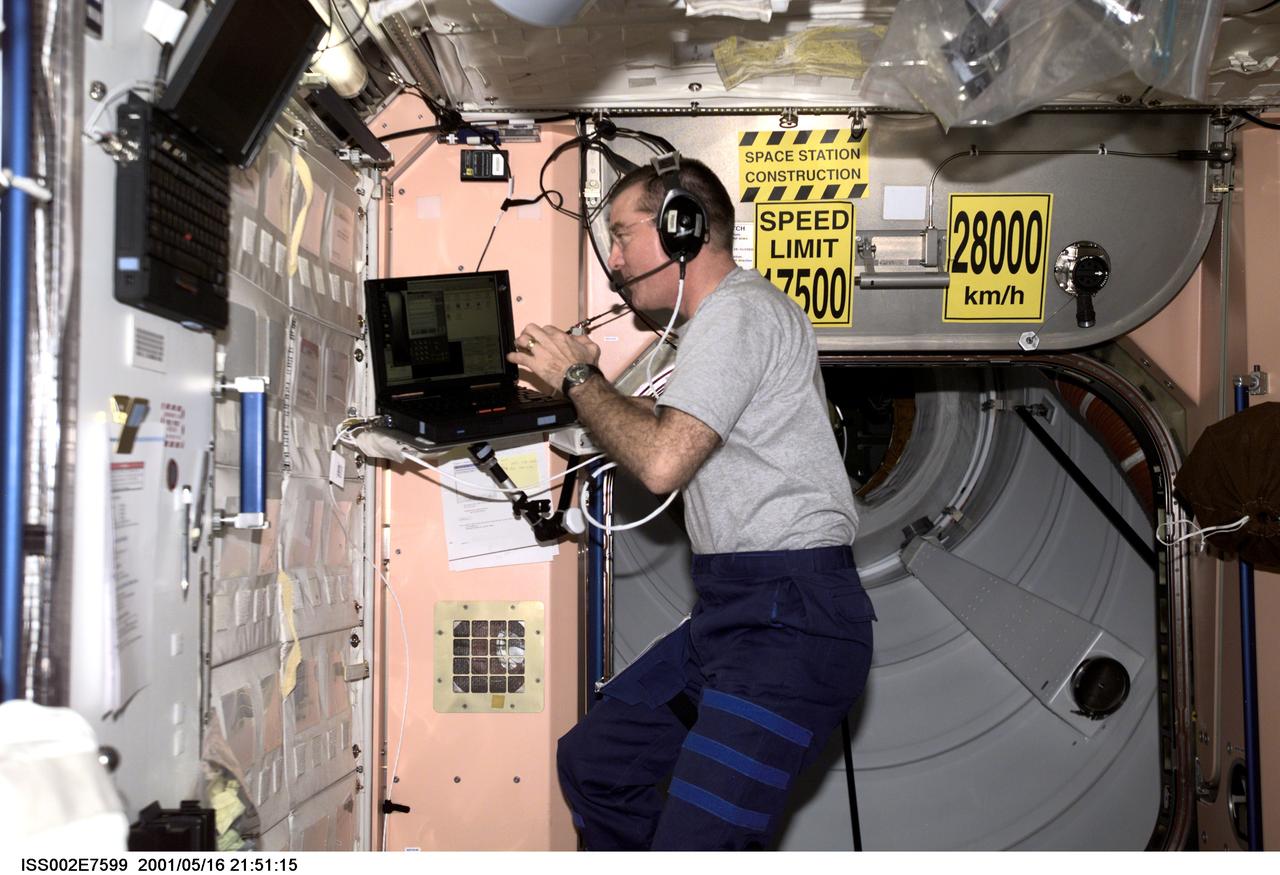
ISS002-E-7599 (16 May 2001) --- James S. Voss, Expedition Two flight engineer, communicates with Mission Control as he works on a laptop computer in Unity Node 1. The image was taken with a digital still camera.
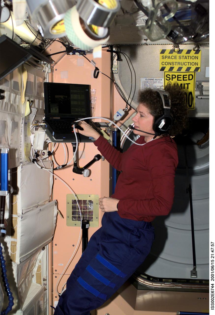
ISS002-E-6744 (15 June 2001) --- Susan J. Helms, Expedition Two flight engineer, talks with mission control while working on a laptop computer in Unity Node 1.
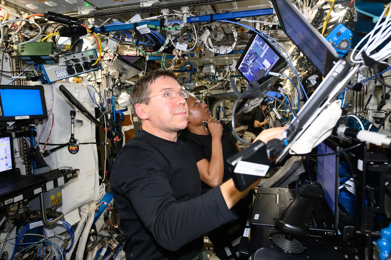
iss071e180163 (June 10, 2024) --- Expedition 71 Flight Engineers Mike Barratt and Jeanette Epps, both NASA astronauts, look at computer monitors on the Destiny laboratory module's robotics workstation that controls the Canadarm2 robotic arm.
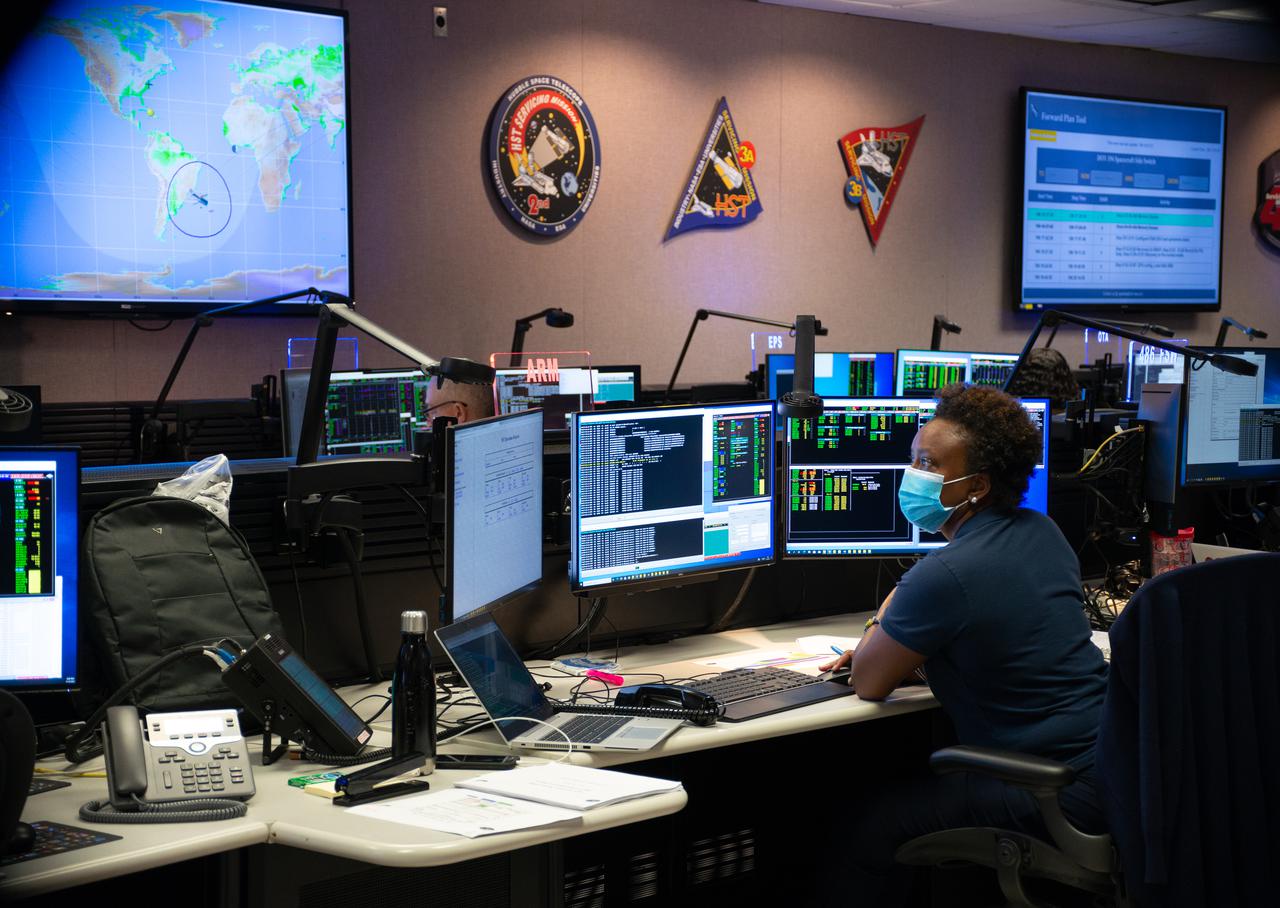
Nzinga Tull, Hubble systems anomaly response manager at NASA’s Goddard Space Flight Center in Greenbelt, Maryland, works in the control room on July 15, 2021, to restore Hubble to full science operations. --- More info: Hubble’s payload computer, which controls and coordinates the observatory’s onboard science instruments, halted suddenly on June 13. When the main computer failed to receive a signal from the payload computer, it automatically placed Hubble’s science instruments into safe mode. That meant the telescope would no longer be doing science while mission specialists analyzed the situation. In response to the anomaly, NASA began a switch to backup spacecraft hardware on Hubble in response to an ongoing problem with its payload computer. This was a multi-day event. Science observations restarted the afternoon of Saturday, July 17.
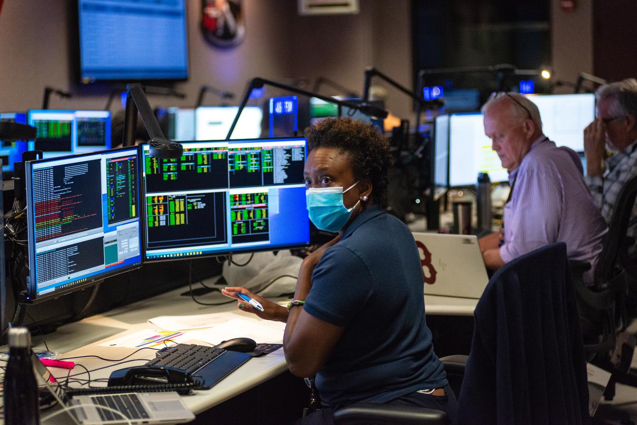
Nzinga Tull, Hubble systems anomaly response manager at NASA’s Goddard Space Flight Center in Greenbelt, Maryland, works in the control room on July 15, 2021, to restore Hubble to full science operations. --- More info: Hubble’s payload computer, which controls and coordinates the observatory’s onboard science instruments, halted suddenly on June 13. When the main computer failed to receive a signal from the payload computer, it automatically placed Hubble’s science instruments into safe mode. That meant the telescope would no longer be doing science while mission specialists analyzed the situation. In response to the anomaly, NASA began a switch to backup spacecraft hardware on Hubble in response to an ongoing problem with its payload computer. This was a multi-day event. Science observations restarted the afternoon of Saturday, July 17.
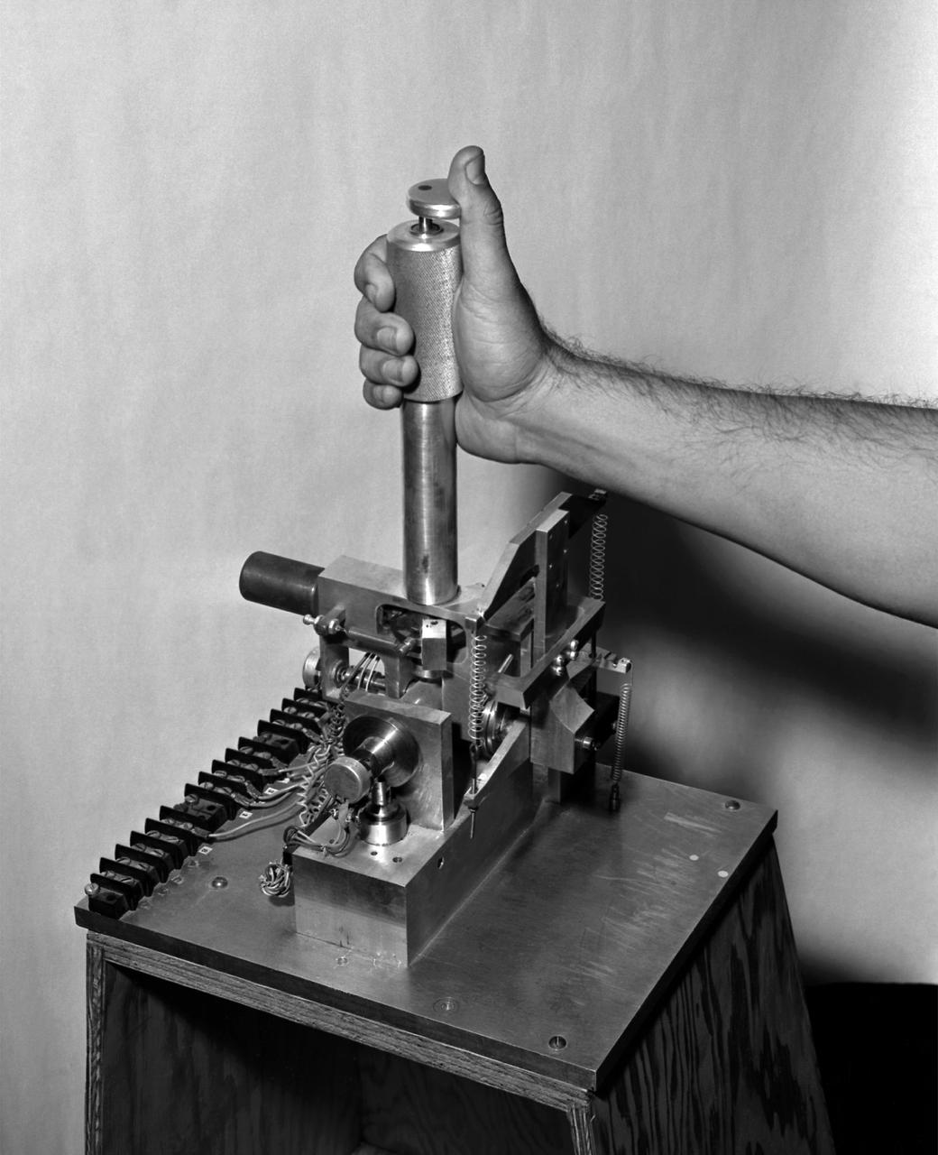
A photo of the control stick used on the Iron Cross Attitude Simulator. Although it resembled today's desktop computer flight sticks, its operation was different. As with a standard control stick, moving it back and forth raised and lowered the nose resulting in changes in pitch. Moving the stick to the right or left raised or lowered the wing, resulted in changes in roll. This control stick had a third axis, not found in standard control sticks. Twisting the stick to the right or left caused the airplane's nose to move horizontally in the same direction, resulting in changes in yaw.
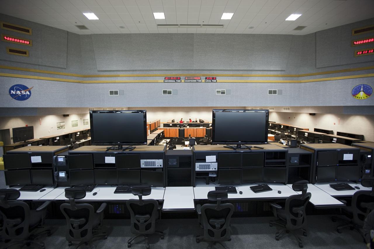
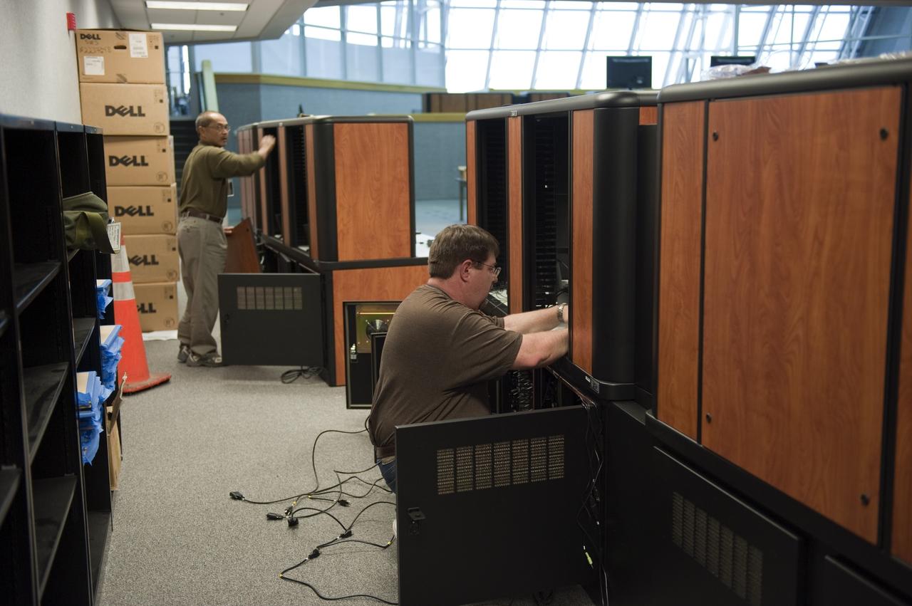
CAPE CANAVERAL, Fla. – Firing Room 1, also known as the Young-Crippen Firing Room, has been outfitted with computer, communications and networking systems to host rockets and spacecraft that are currently under development. The firing room is where the launch of rockets and spacecraft are controlled at NASA's Kennedy Space Center in Florida. Flight controllers also monitor processing and preparations of launch vehicles from the firing room. There are four firing rooms inside the Launch Control Center at Kennedy. Photo credit: NASA/Dmitri Gerondidakis
CAPE CANAVERAL, Fla. – Firing Room 1, also known as the Young-Crippen Firing Room, has been outfitted with computer, communications and networking systems to host rockets and spacecraft that are currently under development. The firing room is where the launch of rockets and spacecraft are controlled at NASA's Kennedy Space Center in Florida. Flight controllers also monitor processing and preparations of launch vehicles from the firing room. There are four firing rooms inside the Launch Control Center at Kennedy. Photo credit: NASA/Dmitri Gerondidakis
NASA engineer Larry Hudson and Ikhana ground crew member James Smith work on a ground validation test with new fiber optic sensors that led to validation flights on the Ikhana aircraft. NASA Dryden Flight Research Center is evaluating an advanced fiber optic-based sensing technology installed on the wings of NASA's Ikhana aircraft. The fiber optic system measures and displays the shape of the aircraft's wings in flight. There are other potential safety applications for the technology, such as vehicle structural health monitoring. If an aircraft structure can be monitored with sensors and a computer can manipulate flight control surfaces to compensate for stresses on the wings, structural control can be established to prevent situations that might otherwise result in a loss of control.
ISS012-E-08724 (16 Nov. 2005) --- Cosmonaut Valery I. Tokarev, Expedition 12 flight engineer representing Russia's Federal Space Agency, uses a laptop computer and hand controller at the Simvol-Ts / TORU workstation in the Zvezda Service Module of the international space station. A docking simulation can be seen on the computer screen as Tokarev conducts onboard training for relocation of the Soyuz TMA-7 spacecraft.

Composite crew module adapter (CMA) panels for the Exploration Flight Test-1 Orion are manufactured using computer numerical control (CNC) machining at NASA's Michoud Assembly Facility in New Orleans on Nov. 11, 2011. Part of Batch image transfer from Flickr.
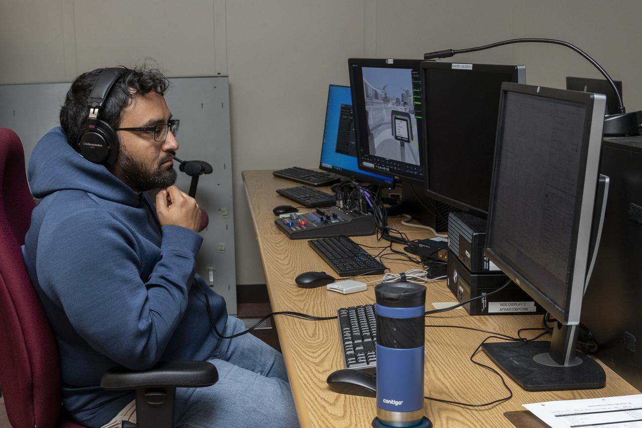
NASA researcher Saravanakumaar Ramia controls the air taxi passenger ride quality simulator by monitoring several computers in the Ride Quality Laboratory at NASA’s Armstrong Flight Research Center in Edwards, California, during an experiment on Oct. 23, 2024. Studies continue in this lab to better understand passenger comfort for future air taxi rides.

ISS023-E-020655 (7 April 2010) --- NASA astronaut Stephanie Wilson (left) and Japan Aerospace Exploration Agency astronaut Naoko Yamazaki, both STS-131 flight engineers, share perhaps their first session at this bank of computers and controls in the Destiny laboratory of the International Space Station.

JSC2006-E-43476 (November 1998) --- Computer-generated artist's rendering of the International Space Station after flight 1A/R. The functional cargo block (FGB) or Zarya Control Module was launched atop a Russian Proton rocket. Zarya provides battery power and fuel storage.
iss064e053505 (April 7, 2021) --- Roscosmos cosmonaut and Expedition 64 Flight Engineer Sergey Kud-Sverchkov conducts training on a computer inside the Zvezda service module. Kud-Sverchkov was practicing the maneuvers necessary for a controlled descent to Earth aboard a Soyuz crew ship.
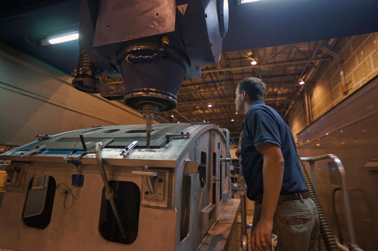
Composite crew module adapter (CMA) panels for the Exploration Flight Test-1 Orion are manufactured using computer numerical control (CNC) machining at NASA's Michoud Assembly Facility in New Orleans on Nov. 11, 2011. Part of Batch image transfer from Flickr.
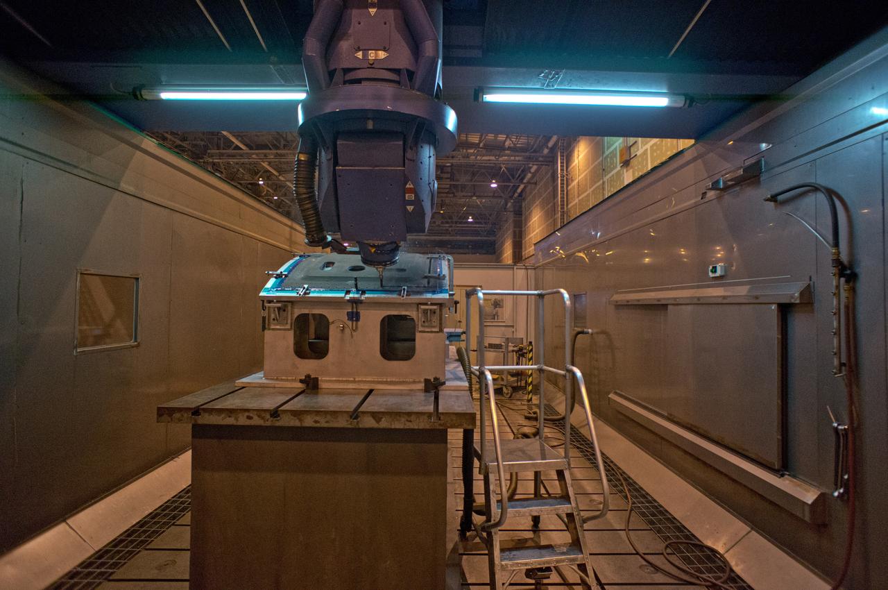
Composite crew module adapter (CMA) panels for the Exploration Flight Test-1 Orion are manufactured using computer numerical control (CNC) machining at NASA's Michoud Assembly Facility in New Orleans on Nov. 11, 2011. Part of Batch image transfer from Flickr.
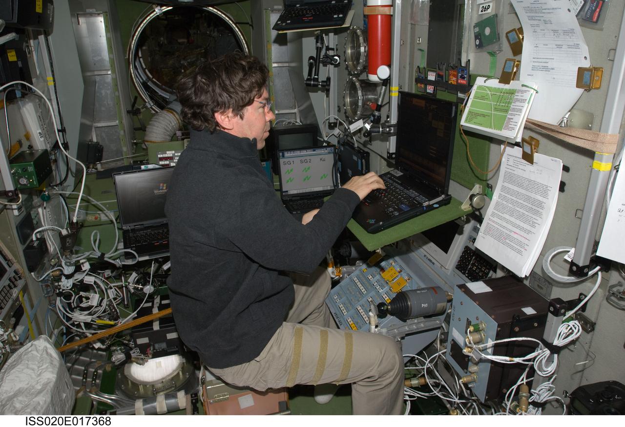
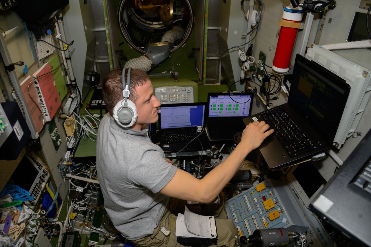
ISS020-E-017368 (6 July 2009) --- NASA astronaut Michael Barratt, Expedition 20 flight engineer, uses a computer at the TORU teleoperated control system in the Zvezda Service Module of the International Space Station while conducting Soyuz descent training to maintain proficiency on systems used for entry and landing in the Soyuz vehicle.

KENNEDY SPACE CENTER, Fla. -- As Space Shuttle Atlantis inches its way to Launch Pad 39A for the second time, it passes the Launch Control Center (right). An attempt to roll out on Jan. 2 incurred a failed computer processor on the crawler transporter and the Shuttle was returned to the Vehicle Assembly Building using a secondary computer processor on the vehicle. Atlantis will fly on mission STS-98, the seventh construction flight to the International Space Station, carrying the U.S. Laboratory, named Destiny. The lab will have five system racks already installed inside the module. After delivery of electronics in the lab, electrically powered attitude control for Control Moment Gyroscopes will be activated. Atlantis is scheduled for launch no earlier than Jan. 19, 2001, with a crew of five
KENNEDY SPACE CENTER, Fla. -- As Space Shuttle Atlantis inches its way to Launch Pad 39A for the second time, it passes the Launch Control Center (right). An attempt to roll out on Jan. 2 incurred a failed computer processor on the crawler transporter and the Shuttle was returned to the Vehicle Assembly Building using a secondary computer processor on the vehicle. Atlantis will fly on mission STS-98, the seventh construction flight to the International Space Station, carrying the U.S. Laboratory, named Destiny. The lab will have five system racks already installed inside the module. After delivery of electronics in the lab, electrically powered attitude control for Control Moment Gyroscopes will be activated. Atlantis is scheduled for launch no earlier than Jan. 19, 2001, with a crew of five
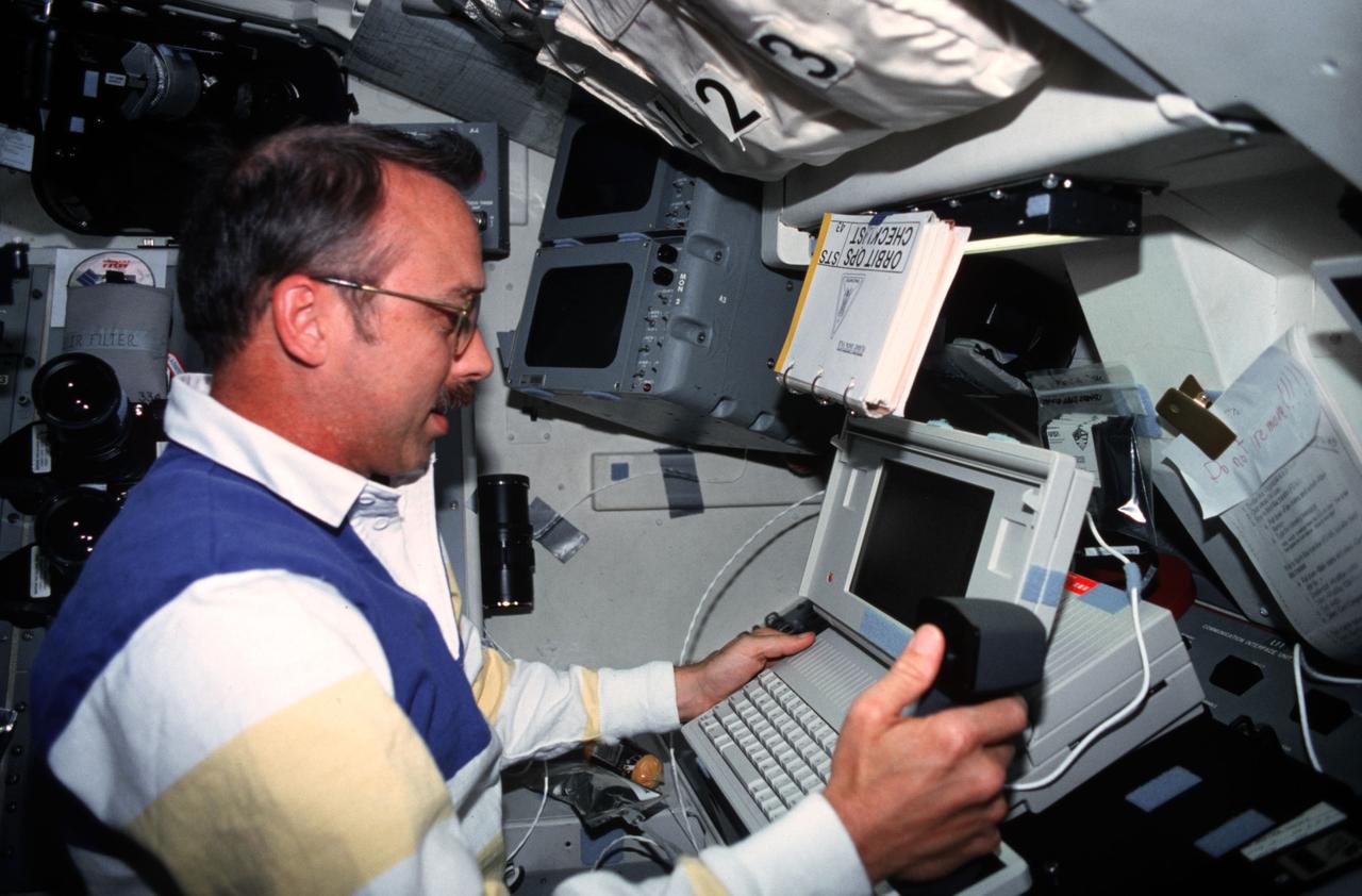
STS036-03-027 (3 March 1990) --- STS-36 Pilot John H. Casper reaches for the shuttle portable onboard computer (SPOC), a laptop computer, while at the pilots station on the forward flight deck of Atlantis, Orbiter Vehicle (OV) 104. Casper, seated in the pilot’s seat, lifts the SPOC from the forward window ledge. Appearing around him are forward crew compartment windows, the head up display (HUD), the flight mirror assembly, and a checklist attached to control panel O3. Casper and four other astronauts spent four days, 10 hours and 19 minutes aboard the spacecraft for a Department of Defense (DOD) devoted mission.
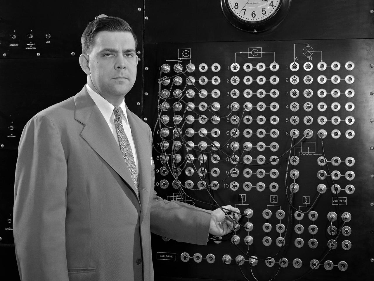
Harry Mergler stands at the control board of a differential analyzer in the new Instrument Research Laboratory at the National Advisory Committee for Aeronautics (NACA) Lewis Flight Propulsion Laboratory. The differential analyzer was a multi-variable analog computation machine devised in 1931 by Massachusetts Institute of Technology researcher and future NACA Committee member Vannevar Bush. The mechanical device could solve computations up to the sixth order, but had to be rewired before each new computation. Mergler modified Bush’s differential analyzer in the late 1940s to calculate droplet trajectories for Lewis’ icing research program. In four days Mergler’s machine could calculate what previously required weeks. NACA Lewis built the Instrument Research Laboratory in 1950 and 1951 to house the large analog computer equipment. The two-story structure also provided offices for the Mechanical Computational Analysis, and Flow Physics sections of the Physics Division. The division had previously operated from the lab’s hangar because of its icing research and flight operations activities. Mergler joined the Instrument Research Section of the Physics Division in 1948 after earning an undergraduate degree in Physics from the Case Institute of Technology. Mergler’s focus was on the synthesis of analog computers with the machine tools used to create compressor and turbine blades for jet engines.
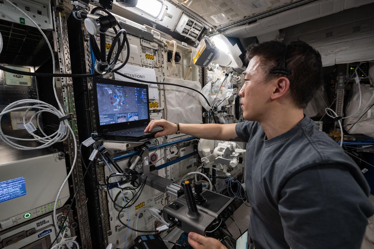
iss073e0416906 (July 21, 2025) --- NASA astronaut and Expedition 73 Flight Engineer Jonny Kim tests space-to-ground robotic controlling methods on a laptop computer inside the International Space Station's Columbus laboratory module. The Surface Avatar experiment explores ways to control robotic vehicles on a planetary surface from an orbiting spacecraft using a variety of technologies including consoles, touchscreens, haptics, and virtual reality goggles that may benefit future space exploration.
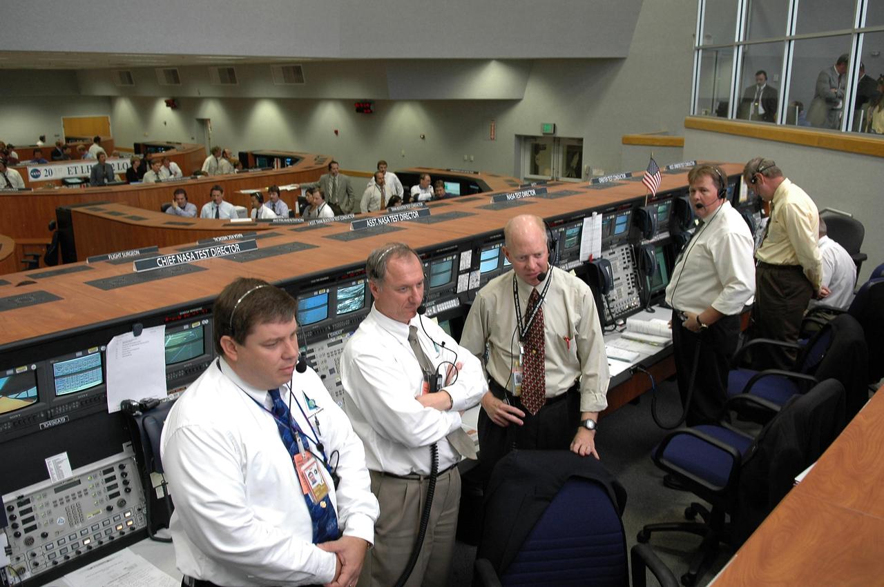
KENNEDY SPACE CENTER, FLA. - Inside the Launch Control Center, KSC officials turn from their computers to watch through the broad windows the launch of Space Shuttle Atlantis on mission STS-115. Second from left is NASA Test Director Pete Nickolenko. Mission STS-115 is the 116th space shuttle flight, the 27th flight for orbiter Atlantis, and the 19th U.S. flight to the International Space Station. sts-115 is scheduled to last 11 days with a planned landing at KSC. Photo credit: NASA/Kim Shiflett
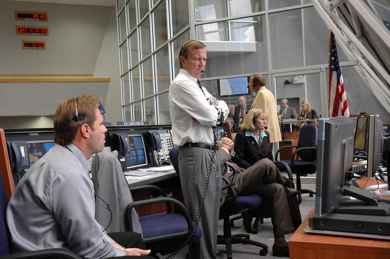
KENNEDY SPACE CENTER, FLA. - Inside the Launch Control Center, Shuttle Launch Director Mike Leinbach (center, standing) watches the computer screen as cameras document Space Shuttle Atlantis' climb toward space on mission STS-115. Mission STS-115 is the 116th space shuttle flight, the 27th flight for orbiter Atlantis, and the 19th U.S. flight to the International Space Station. sts-115 is scheduled to last 11 days with a planned landing at KSC. Photo credit: NASA/Kim Shiflett

KENNEDY SPACE CENTER, Fla. -- Space Shuttle Atlantis, on its Mobile Launcher Platform, rolls out to Launch Pad 39A for the second time. An attempt to roll out on Jan. 2 incurred a failed computer processor on the first crawler transporter. The Shuttle was returned to the VAB using a secondary computer processor on the vehicle. Atlantis will fly on mission STS-98, the seventh construction flight to the International Space Station, carrying the U.S. Laboratory, named Destiny. The lab module will have five system racks already installed inside. After delivery of electronics in the lab, electrically powered attitude control for Control Moment Gyroscopes will be activated. Atlantis is scheduled for launch no earlier than Jan. 19, 2001, with a crew of five
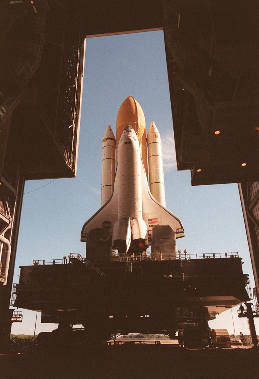
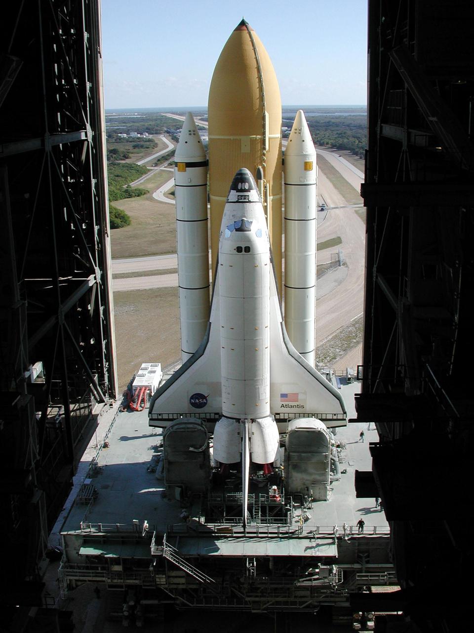
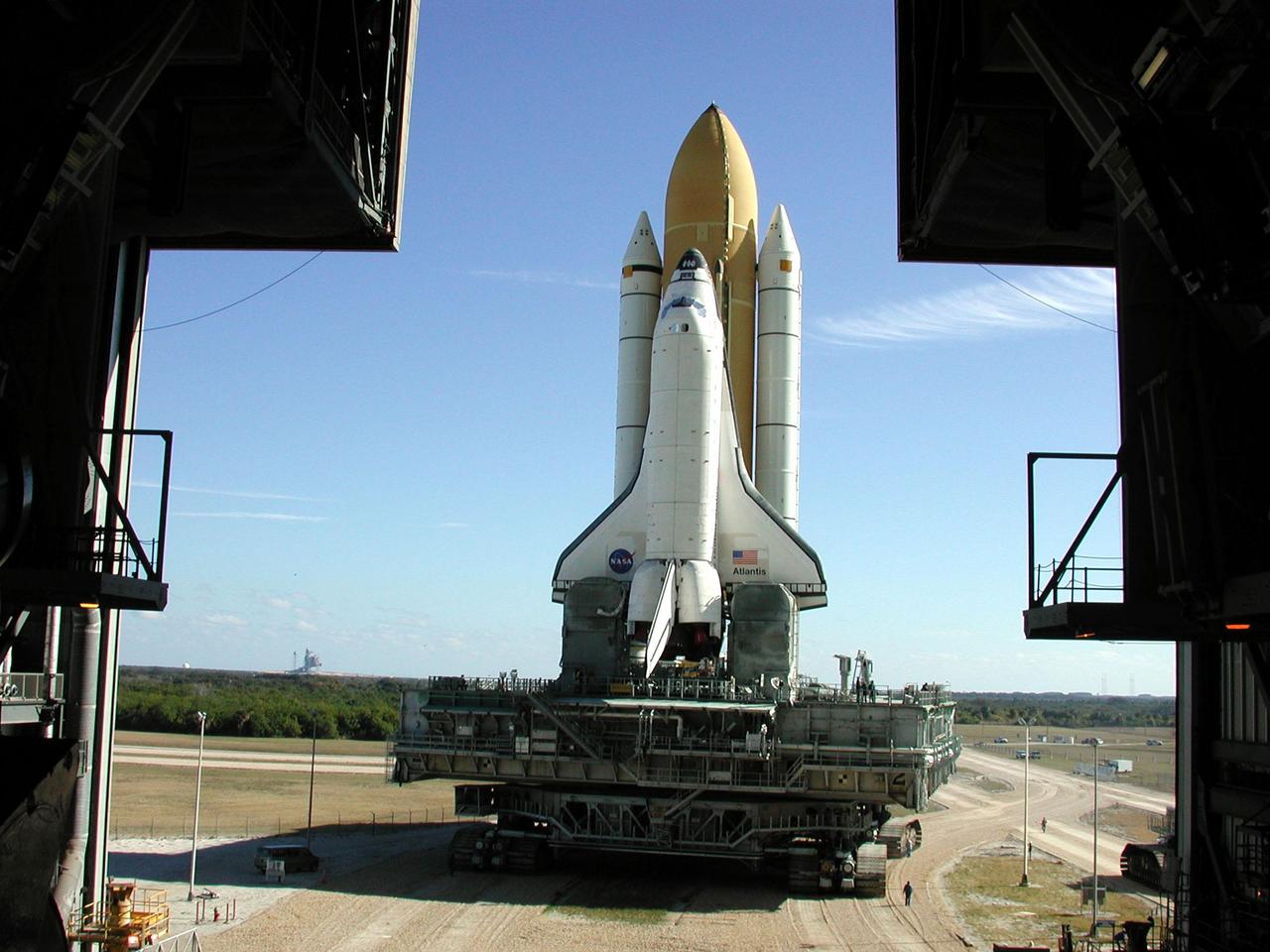
KENNEDY SPACE CENTER, Fla. -- Space Shuttle Atlantis inches its way out the doors of the Vehicle Assembly Building as it begins rolling out to Launch Pad 39A for the second time. An attempt to roll out on Jan. 2 incurred a failed computer processor on the crawler transporter and the Shuttle was returned to the Vehicle Assembly Building using a secondary computer processor on the vehicle. Atlantis will fly on mission STS-98, the seventh construction flight to the International Space Station, carrying the U.S. Laboratory, named Destiny. The lab will have five system racks already installed inside the module. After delivery of electronics in the lab, electrically powered attitude control for Control Moment Gyroscopes will be activated. Atlantis is scheduled for launch no earlier than Jan. 19, 2001, with a crew of five
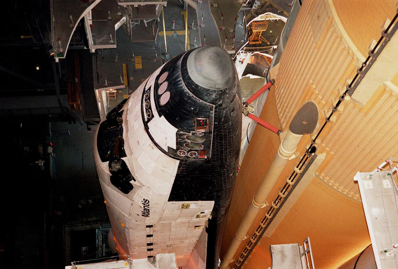
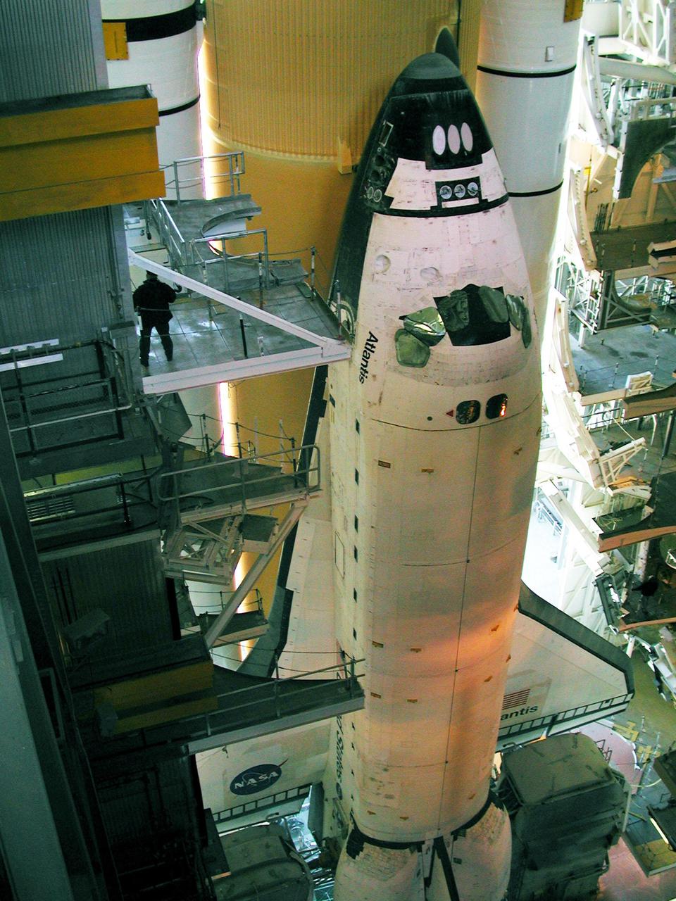
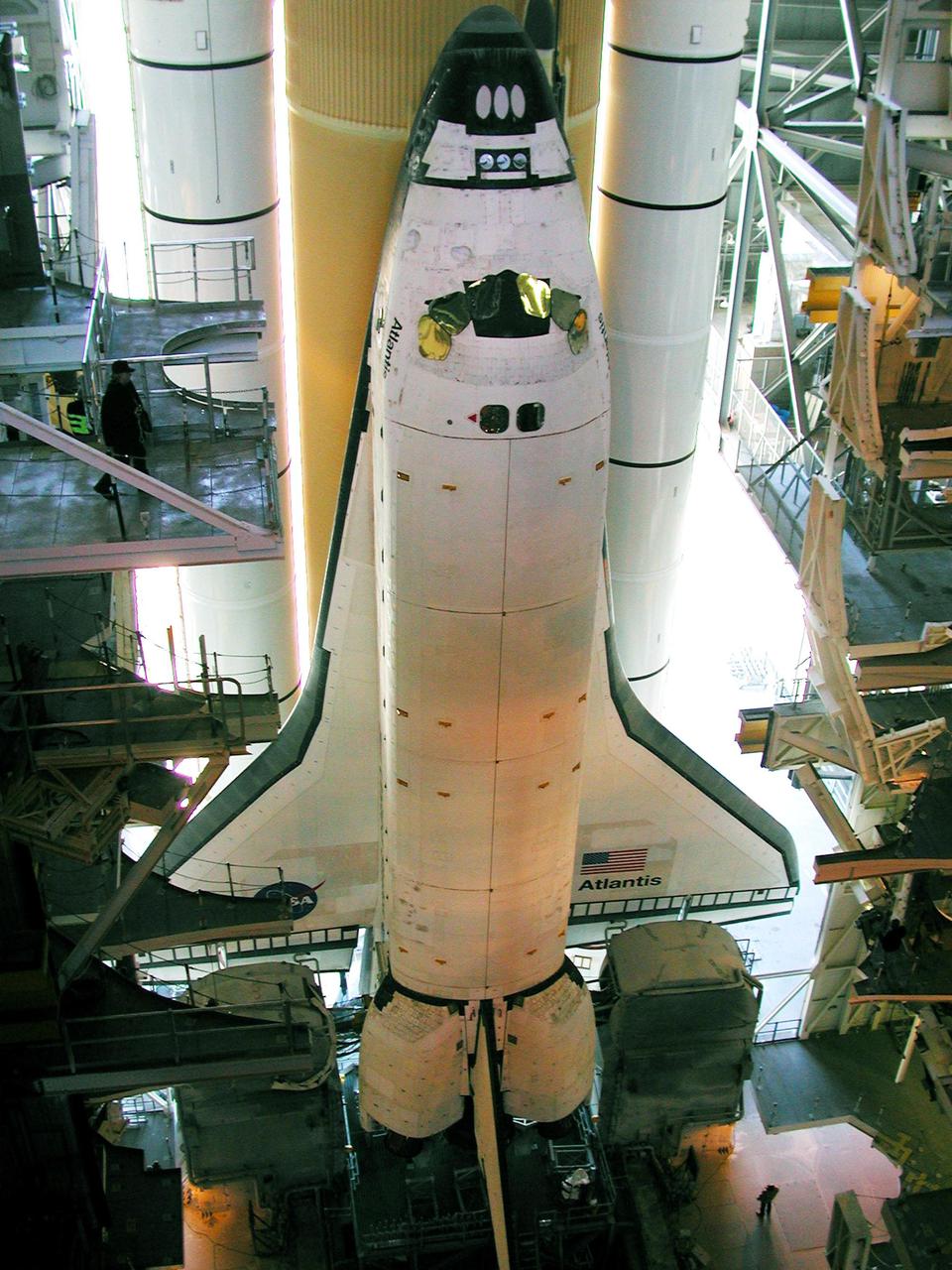
KENNEDY SPACE CENTER, Fla. -- The nose of Atlantis is seen in this closeup, along with the braces that attach it to the external tank at right. Space Shuttle Atlantis is making its second rollout attempt to Launch Pad 39A. An attempt to roll out on Jan. 2 incurred a failed computer processor on the crawler transporter and the Shuttle was returned to the Vehicle Assembly Building using a secondary computer processor on the vehicle. Atlantis will fly on mission STS-98, the seventh construction flight to the International Space Station, carrying the U.S. Laboratory, named Destiny. The lab will have five system racks already installed inside the module. After delivery of electronics in the lab, electrically powered attitude control for Control Moment Gyroscopes will be activated. Atlantis is scheduled for launch no earlier than Jan. 19, 2001, with a crew of five
KENNEDY SPACE CENTER, Fla. -- Space Shuttle Atlantis, on its Mobile Launcher Platform, is once again ready to roll out to Launch Pad 39A, this time on another crawler transporter. An attempt to roll out on Jan. 2 incurred a failed computer processor on the first crawler transporter. Using a secondary computer processor on the vehicle, the Shuttle was returned to the Vehicle Assembly Building. Atlantis will fly on mission STS-98, the seventh construction flight to the International Space Station, carrying the U.S. Laboratory, named Destiny. The lab module will have five system racks already installed inside. After delivery of electronics in the lab, electrically powered attitude control for Control Moment Gyroscopes will be activated. Atlantis is scheduled for launch no earlier than Jan. 19, 2001, with a crew of five

KENNEDY SPACE CENTER, Fla. -- Daylight glows from behind Space Shuttle Atlantis as it begins rollout to Launch Pad 39A for the second time. An attempt to roll out on Jan. 2 incurred a failed computer processor on the crawler transporter and the Shuttle was returned to the Vehicle Assembly Building using a secondary computer processor on the vehicle. Atlantis will fly on mission STS-98, the seventh construction flight to the International Space Station, carrying the U.S. Laboratory, named Destiny. The lab will have five system racks already installed inside the module. After delivery of electronics in the lab, electrically powered attitude control for Control Moment Gyroscopes will be activated. Atlantis is scheduled for launch no earlier than Jan. 19, 2001, with a crew of five

KENNEDY SPACE CENTER, Fla. -- Under wispy white morning clouds, Space Shuttle Atlantis approaches Launch Pad 39A, which shows the Rotating Service Structure open (left) and the Fixed Service Structure (right). At the RSS, the payload canister is being lifted up to the Payload Changeout Room. This is the Shuttle’s second attempt at rollout. Jan. 2 a failed computer processor on the crawler transporter aborted the rollout and the Shuttle was returned to the Vehicle Assembly Building using a secondary computer processor on the vehicle. Atlantis will fly on mission STS-98, the seventh construction flight to the International Space Station, carrying the U.S. Laboratory, named Destiny. The lab will have five system racks already installed inside the module. After delivery of electronics in the lab, electrically powered attitude control for Control Moment Gyroscopes will be activated. Atlantis is scheduled for launch no earlier than Jan. 19, 2001, with a crew of five
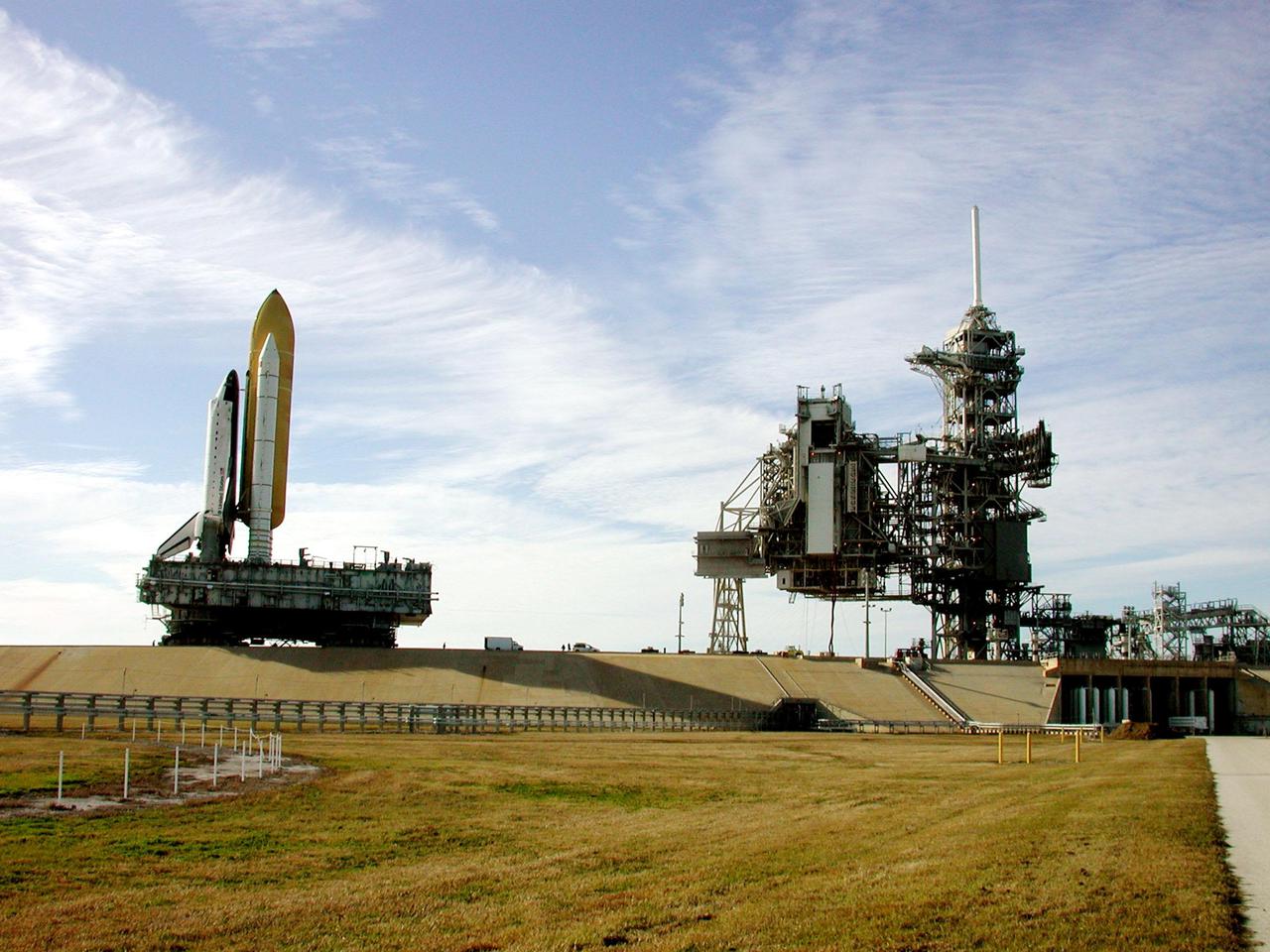
KENNEDY SPACE CENTER, Fla. -- Under wispy white morning clouds, Space Shuttle Atlantis approaches Launch Pad 39A, which shows the Rotating Service Structure open (left) and the Fixed Service Structure (right). At the RSS, the payload canister is being lifted up to the Payload Changeout Room. This is the Shuttle’s second attempt at rollout. Jan. 2 a failed computer processor on the crawler transporter aborted the rollout and the Shuttle was returned to the Vehicle Assembly Building using a secondary computer processor on the vehicle. Atlantis will fly on mission STS-98, the seventh construction flight to the International Space Station, carrying the U.S. Laboratory, named Destiny. The lab will have five system racks already installed inside the module. After delivery of electronics in the lab, electrically powered attitude control for Control Moment Gyroscopes will be activated. Atlantis is scheduled for launch no earlier than Jan. 19, 2001, with a crew of five
KENNEDY SPACE CENTER, Fla. -- Space Shuttle Atlantis, on its Mobile Launcher Platform, begins rolling through the open doors of the Vehicle Assembly Building to Launch Pad 39A, this time on another crawler transporter. An attempt to roll out on Jan. 2 incurred a failed computer processor on the first crawler transporter. The Shuttle was returned to the VAB using a secondary computer processor on the vehicle. Atlantis will fly on mission STS-98, the seventh construction flight to the International Space Station, carrying the U.S. Laboratory, named Destiny. The lab module will have five system racks already installed inside. After delivery of electronics in the lab, electrically powered attitude control for Control Moment Gyroscopes will be activated. Atlantis is scheduled for launch no earlier than Jan. 19, 2001, with a crew of five

KENNEDY SPACE CENTER, Fla. -- Space Shuttle Atlantis inches its way out the doors of the Vehicle Assembly Building as it begins rolling out to Launch Pad 39A for the second time. An attempt to roll out on Jan. 2 incurred a failed computer processor on the crawler transporter and the Shuttle was returned to the Vehicle Assembly Building using a secondary computer processor on the vehicle. Atlantis will fly on mission STS-98, the seventh construction flight to the International Space Station, carrying the U.S. Laboratory, named Destiny. The lab will have five system racks already installed inside the module. After delivery of electronics in the lab, electrically powered attitude control for Control Moment Gyroscopes will be activated. Atlantis is scheduled for launch no earlier than Jan. 19, 2001, with a crew of five

KENNEDY SPACE CENTER, Fla. -- Daylight glows from behind Space Shuttle Atlantis as it begins rollout to Launch Pad 39A for the second time. An attempt to roll out on Jan. 2 incurred a failed computer processor on the crawler transporter and the Shuttle was returned to the Vehicle Assembly Building using a secondary computer processor on the vehicle. Atlantis will fly on mission STS-98, the seventh construction flight to the International Space Station, carrying the U.S. Laboratory, named Destiny. The lab will have five system racks already installed inside the module. After delivery of electronics in the lab, electrically powered attitude control for Control Moment Gyroscopes will be activated. Atlantis is scheduled for launch no earlier than Jan. 19, 2001, with a crew of five
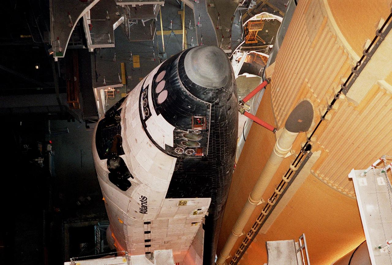
KENNEDY SPACE CENTER, Fla. -- The nose of Atlantis is seen in this closeup, along with the braces that attach it to the external tank at right. Space Shuttle Atlantis is making its second rollout attempt to Launch Pad 39A. An attempt to roll out on Jan. 2 incurred a failed computer processor on the crawler transporter and the Shuttle was returned to the Vehicle Assembly Building using a secondary computer processor on the vehicle. Atlantis will fly on mission STS-98, the seventh construction flight to the International Space Station, carrying the U.S. Laboratory, named Destiny. The lab will have five system racks already installed inside the module. After delivery of electronics in the lab, electrically powered attitude control for Control Moment Gyroscopes will be activated. Atlantis is scheduled for launch no earlier than Jan. 19, 2001, with a crew of five
KENNEDY SPACE CENTER, Fla. -- Space Shuttle Atlantis, on its Mobile Launcher Platform, begins to roll out to Launch Pad 39A, this time on another crawler transporter. An attempt to roll out on Jan. 2 incurred a failed computer processor on the first crawler transporter. The Shuttle was returned to the Vehicle Assembly Building Using a secondary computer processor on the vehicle. Atlantis will fly on mission STS-98, the seventh construction flight to the International Space Station, carrying the U.S. Laboratory, named Destiny. The lab module will have five system racks already installed inside. After delivery of electronics in the lab, electrically powered attitude control for Control Moment Gyroscopes will be activated. Atlantis is scheduled for launch no earlier than Jan. 19, 2001, with a crew of five

KENNEDY SPACE CENTER, Fla. -- Space Shuttle Atlantis, on its Mobile Launcher Platform, begins rolling through the open doors of the Vehicle Assembly Building to Launch Pad 39A, this time on another crawler transporter. An attempt to roll out on Jan. 2 incurred a failed computer processor on the first crawler transporter. The Shuttle was returned to the VAB using a secondary computer processor on the vehicle. Atlantis will fly on mission STS-98, the seventh construction flight to the International Space Station, carrying the U.S. Laboratory, named Destiny. The lab module will have five system racks already installed inside. After delivery of electronics in the lab, electrically powered attitude control for Control Moment Gyroscopes will be activated. Atlantis is scheduled for launch no earlier than Jan. 19, 2001, with a crew of five

KENNEDY SPACE CENTER, Fla. -- Space Shuttle Atlantis, on its Mobile Launcher Platform, begins to roll out to Launch Pad 39A, this time on another crawler transporter. An attempt to roll out on Jan. 2 incurred a failed computer processor on the first crawler transporter. The Shuttle was returned to the Vehicle Assembly Building Using a secondary computer processor on the vehicle. Atlantis will fly on mission STS-98, the seventh construction flight to the International Space Station, carrying the U.S. Laboratory, named Destiny. The lab module will have five system racks already installed inside. After delivery of electronics in the lab, electrically powered attitude control for Control Moment Gyroscopes will be activated. Atlantis is scheduled for launch no earlier than Jan. 19, 2001, with a crew of five
KENNEDY SPACE CENTER, Fla. -- Space Shuttle Atlantis, on its Mobile Launcher Platform, rolls out to Launch Pad 39A for the second time. An attempt to roll out on Jan. 2 incurred a failed computer processor on the first crawler transporter. The Shuttle was returned to the VAB using a secondary computer processor on the vehicle. Atlantis will fly on mission STS-98, the seventh construction flight to the International Space Station, carrying the U.S. Laboratory, named Destiny. The lab module will have five system racks already installed inside. After delivery of electronics in the lab, electrically powered attitude control for Control Moment Gyroscopes will be activated. Atlantis is scheduled for launch no earlier than Jan. 19, 2001, with a crew of five
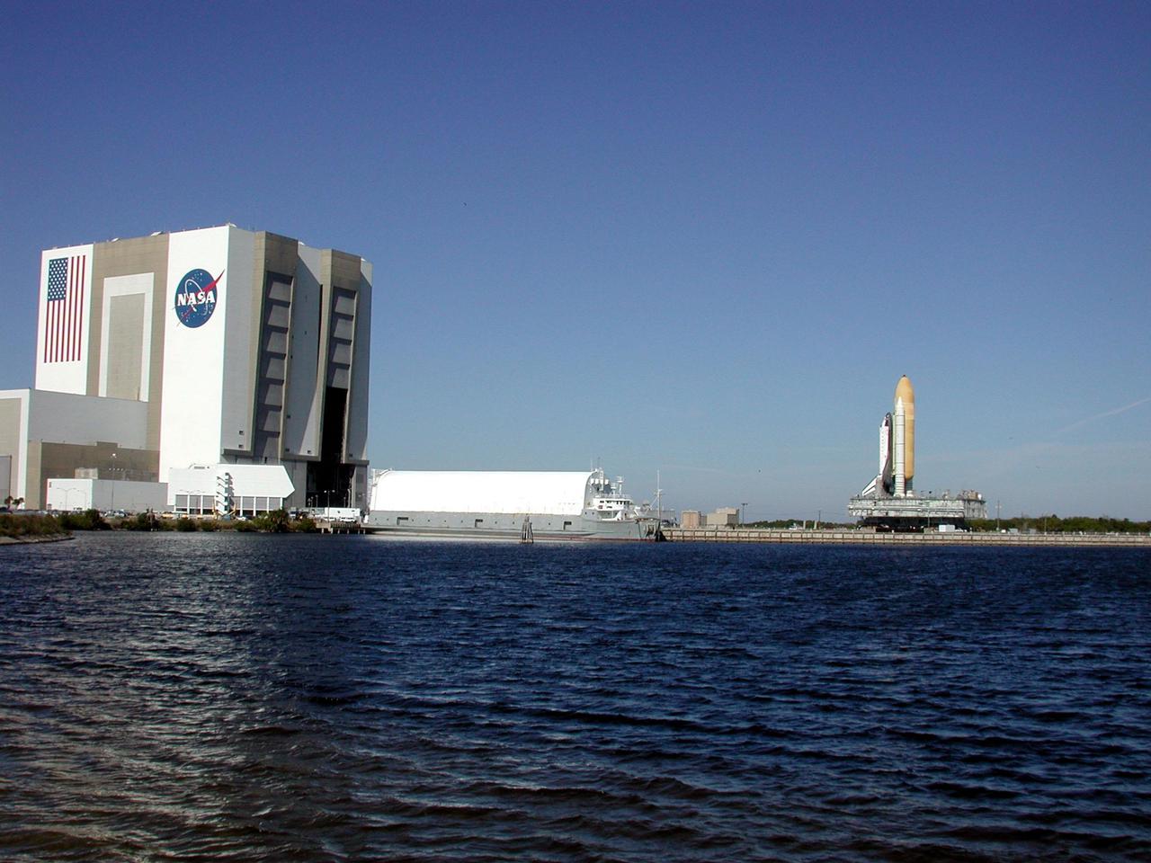
KENNEDY SPACE CENTER, Fla. -- Space Shuttle Atlantis, on its Mobile Launcher Platform, is seen from across the turn basin as it rolls out to Launch Pad 39A for the second time. An attempt to roll out on Jan. 2 incurred a failed computer processor on the first crawler transporter. The Shuttle was returned to the VAB using a secondary computer processor on the vehicle. Atlantis will fly on mission STS-98, the seventh construction flight to the International Space Station, carrying the U.S. Laboratory, named Destiny. The lab module will have five system racks already installed inside. After delivery of electronics in the lab, electrically powered attitude control for Control Moment Gyroscopes will be activated. Atlantis is scheduled for launch no earlier than Jan. 19, 2001, with a crew of five
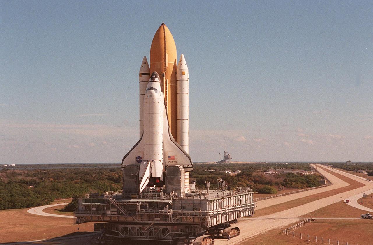
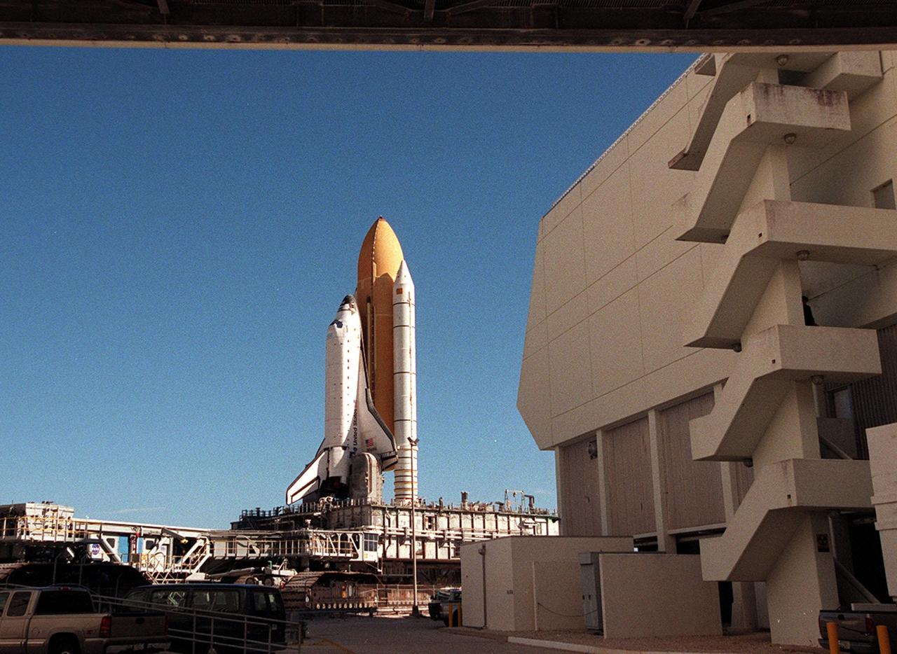
KENNEDY SPACE CENTER, Fla. -- Space Shuttle Atlantis inches its way to Launch Pad 39A for the second time. In the background is the launch pad; the crawlerway leading to it (on the right) extends toward the horizon. An attempt to roll out on Jan. 2 incurred a failed computer processor on the crawler transporter and the Shuttle was returned to the Vehicle Assembly Building using a secondary computer processor on the vehicle. Atlantis will fly on mission STS-98, the seventh construction flight to the International Space Station, carrying the U.S. Laboratory, named Destiny. The lab will have five system racks already installed inside the module. After delivery of electronics in the lab, electrically powered attitude control for Control Moment Gyroscopes will be activated. Atlantis is scheduled for launch no earlier than Jan. 19, 2001, with a crew of five

KENNEDY SPACE CENTER, Fla. -- Space Shuttle Atlantis inches its way to Launch Pad 39A for the second time. In the background is the launch pad; the crawlerway leading to it (on the right) extends toward the horizon. An attempt to roll out on Jan. 2 incurred a failed computer processor on the crawler transporter and the Shuttle was returned to the Vehicle Assembly Building using a secondary computer processor on the vehicle. Atlantis will fly on mission STS-98, the seventh construction flight to the International Space Station, carrying the U.S. Laboratory, named Destiny. The lab will have five system racks already installed inside the module. After delivery of electronics in the lab, electrically powered attitude control for Control Moment Gyroscopes will be activated. Atlantis is scheduled for launch no earlier than Jan. 19, 2001, with a crew of five
STS043-03-009 (5 Aug 1991) ---- Astronaut John E. Blaha is pictured executing development test objective (DTO) 1208, Space Station Cursor Control Device Evaluation II and advanced applications. The purpose of the Cursor Control Device Experiment is to evaluate human performance under space flight conditions of cursor control devices which are similar to the devices under consideration for use onboard Space Station computers. Here, the mission commander uses a thumbball/handgrip control device. Each crewmember evaluated the different types of cursor control devices during the nine-day STS-43 mission. Other methods of cursor control evaluated were the built-in trackball, a side mounted trackball with restraints and an optical pad with mouse.
STS043-14-034 (2-11 Aug 1991) --- Astronaut James C. Adamson is pictured executing Development Test Objective (DTO) 1208, Space Station Cursor Control Device Evaluation II and Advanced Applications. The purpose of the Cursor Control Device Experiment is to evaluate human performance under space flight conditions of cursor control devices which are similar to the devices under consideration for use onboard space station computers. Here, the mission specialists uses a thumbball/handgrip control device. Each crewmember evaluated the different types of cursor control devices during the nine-day STS-43 mission. Other methods of cursor control evaluated were the built-in trackball, a side mounted trackball with restraints and an optical pad with mouse.
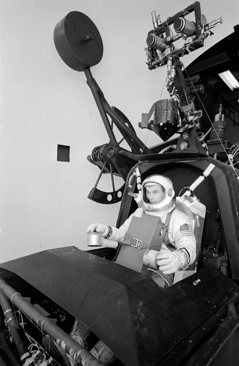
S66-27990 (March 1966) --- Astronaut Eugene A. Cernan, pilot for the Gemini-9 spaceflight, works out procedures for his historic space excursion in a unique manned Aerospace Flight Simulator at LTV Corp. at Dallas, Texas. The LTV simulator is used frequently by NASA astronauts for a variety of space programs maneuvers to provide many of the sensations and visual scenes of actual spaceflight. Controlled through a complex of computers, the device makes it possible for the astronauts to work out procedures, solve problems and simulate missions in real time with great accuracy. The astronaut rides in a spacecraft-like gondola which moves in roll, pitch and yaw in response to his controls and accurate computer inputs. The simulator's usual spacecraft displays and canopy have been removed and AMU backpack complete with control electronics installed. The astronaut makes his simulated flight in an inflated pressure suit and with the NASA-developed Extravehicular Life Support system chest pack which will be used in the Gemini flight. Photo credit: NASA
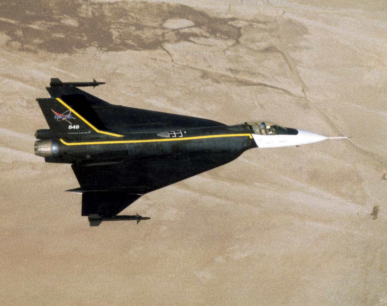
An image of the F-16XL #1 during its functional flight check of the Digital Flight Control System (DFCS) on December 16, 1997. The mission was flown by NASA research pilot Dana Purifoy, and lasted 1 hour and 25 minutes. The tests included pilot familiarly, functional check, and handling qualities evaluation maneuvers to a speed of Mach 0.6 and 300 knots. Purifoy completed all the briefed data points with no problems, and reported that the DFCS handled as well, if not better than the analog computer system that it replaced.
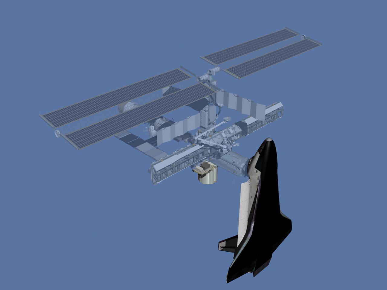
JSC2006-E-43496 (July 2005) --- Computer-generated artist's rendering of the International Space Station after flight STS-114/LF1. The Space Shuttle Discovery Return to Flight mission carried supplies and equipment inside the Italian-built Raffaello Multi-Purpose Logistics Module (MPLM) to the station. A faulty Control Moment Gyro was removed and replaced and External Stowage Platform-2 (ESP2) was installed.
STS064-311-031 (10 Sept. 1994) --- Astronaut Mark C. Lee, STS-64 mission specialist, at a Payload General Support Computer (PGSC) on the space shuttle Discovery's flight deck, talks to ground controllers about the Shuttle Plume Impingement Flight Experiment (SPIFEX). Astronaut L. Blaine Hammond, pilot, is partially visible in the background. Photo credit: NASA or National Aeronautics and Space Administration
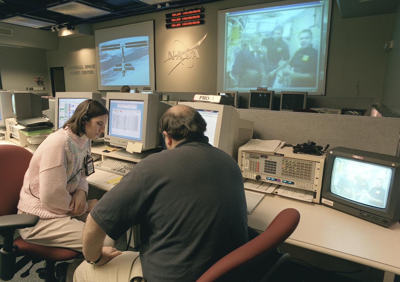
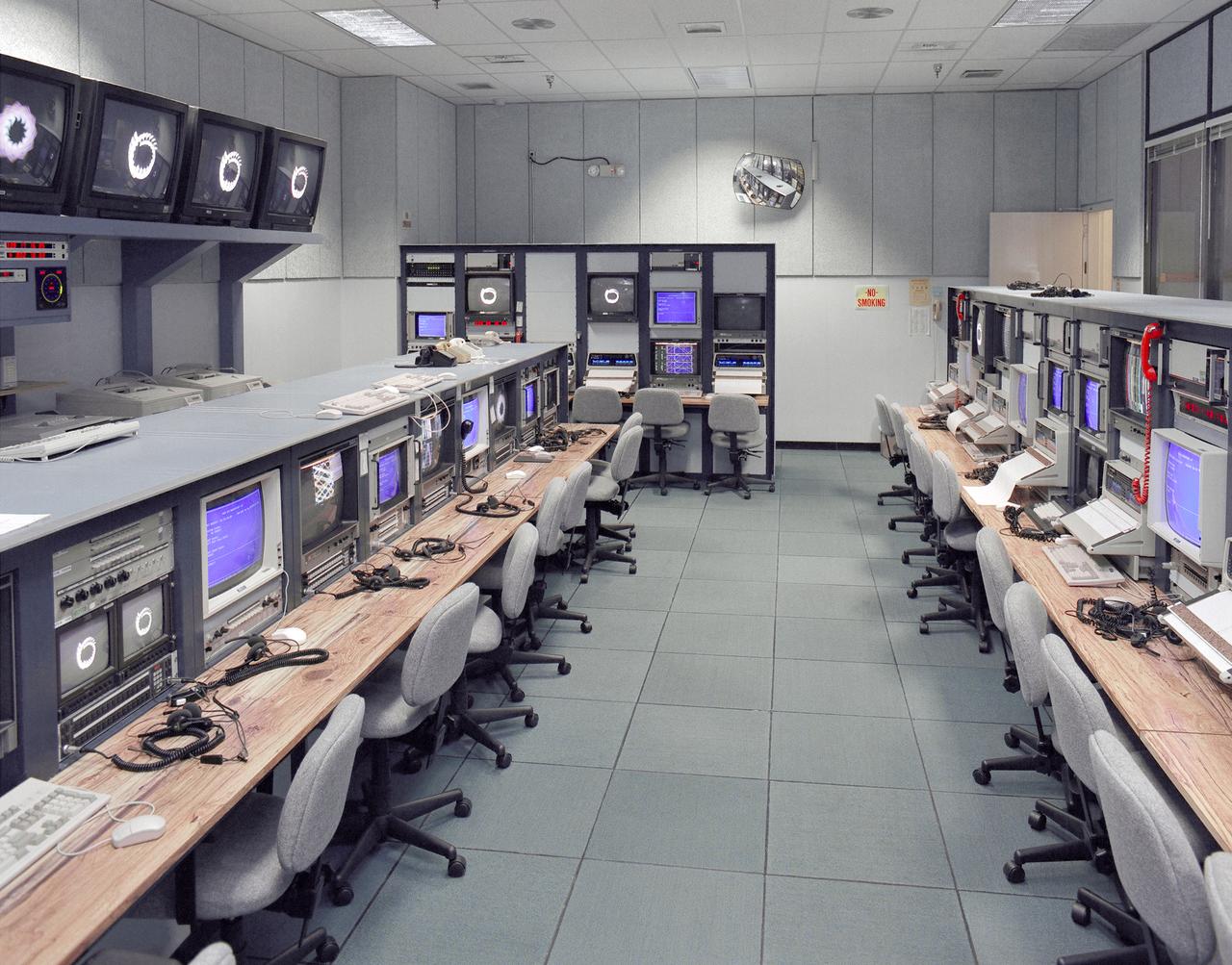
The Payload Operations Center (POC) is the science command post for the International Space Station (ISS). Located at NASA's Marshall Space Flight Center in Huntsville, Alabama, it is the focal point for American and international science activities aboard the ISS. The POC's unique capabilities allow science experts and researchers around the world to perform cutting-edge science in the unique microgravity environment of space. The POC is staffed around the clock by shifts of payload flight controllers. At any given time, 8 to 10 flight controllers are on consoles operating, plarning for, and controlling various systems and payloads. This photograph shows a Payload Rack Officer (PRO) at a work station. The PRO is linked by a computer to all payload racks aboard the ISS. The PRO monitors and configures the resources and environment for science experiments including EXPRESS Racks, multiple-payload racks designed for commercial payloads.
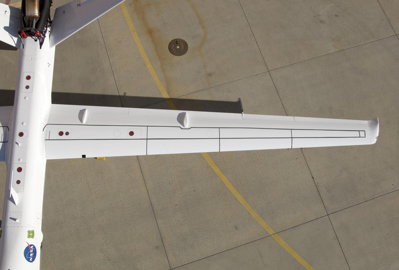
Although the new fiber optic sensors on the Ikhana, which are located on fibers that are the diameter of a human hair, are not visible, the sealant used to cover them can be seen in this view from above the left wing. NASA Dryden Flight Research Center is evaluating an advanced fiber optic-based sensing technology installed on the wings of NASA's Ikhana aircraft. The fiber optic system measures and displays the shape of the aircraft's wings in flight. There are other potential safety applications for the technology, such as vehicle structural health monitoring. If an aircraft structure can be monitored with sensors and a computer can manipulate flight control surfaces to compensate for stresses on the wings, structural control can be established to prevent situations that might otherwise result in a loss of control.
Ikhana fiber optic wing shape sensor team: clockwise from left, Anthony "Nino" Piazza, Allen Parker, William Ko and Lance Richards. The sensors, located along a fiber the thickness of a human hair, aren't visible in the center of the Ikhana aircraft's left wing. NASA Dryden Flight Research Center is evaluating an advanced fiber optic-based sensing technology installed on the wings of NASA's Ikhana aircraft. The fiber optic system measures and displays the shape of the aircraft's wings in flight. There are other potential safety applications for the technology, such as vehicle structural health monitoring. If an aircraft structure can be monitored with sensors and a computer can manipulate flight control surfaces to compensate for stresses on the wings, structural control can be established to prevent situations that might otherwise result in a loss of control.
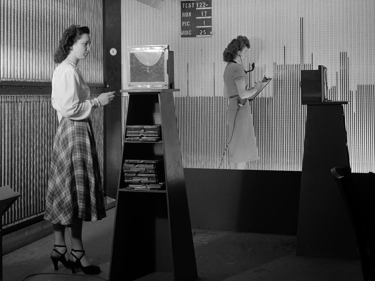
Female computers at the National Advisory Committee for Aeronautics (NACA) Lewis Flight Propulsion Laboratory copy pressure readings from rows of manometers below the 18- by 18-inch Supersonic Wind Tunnel. The computers obtained test data from the manometers and other instruments, made the initial computations, and plotted the information graphically. Based on these computations, the researchers planned their next test or summarized their findings in a report. Manometers were mercury-filled glass tubes that were used to indicate different pressure levels from inside the test facility or from the test article. Manometers look and function very similarly to thermometers. Dozens of pressure sensing instruments were installed for each test. Each was connected to a manometer tube located inside the control room. The mercury inside the manometer rose and fell with the pressure levels. The dark mercury can be seen in this photograph at different levels within the tubes. Since this activity was dynamic, it was necessary to note the levels at given points during the test. This was done using both computer notations and photography.
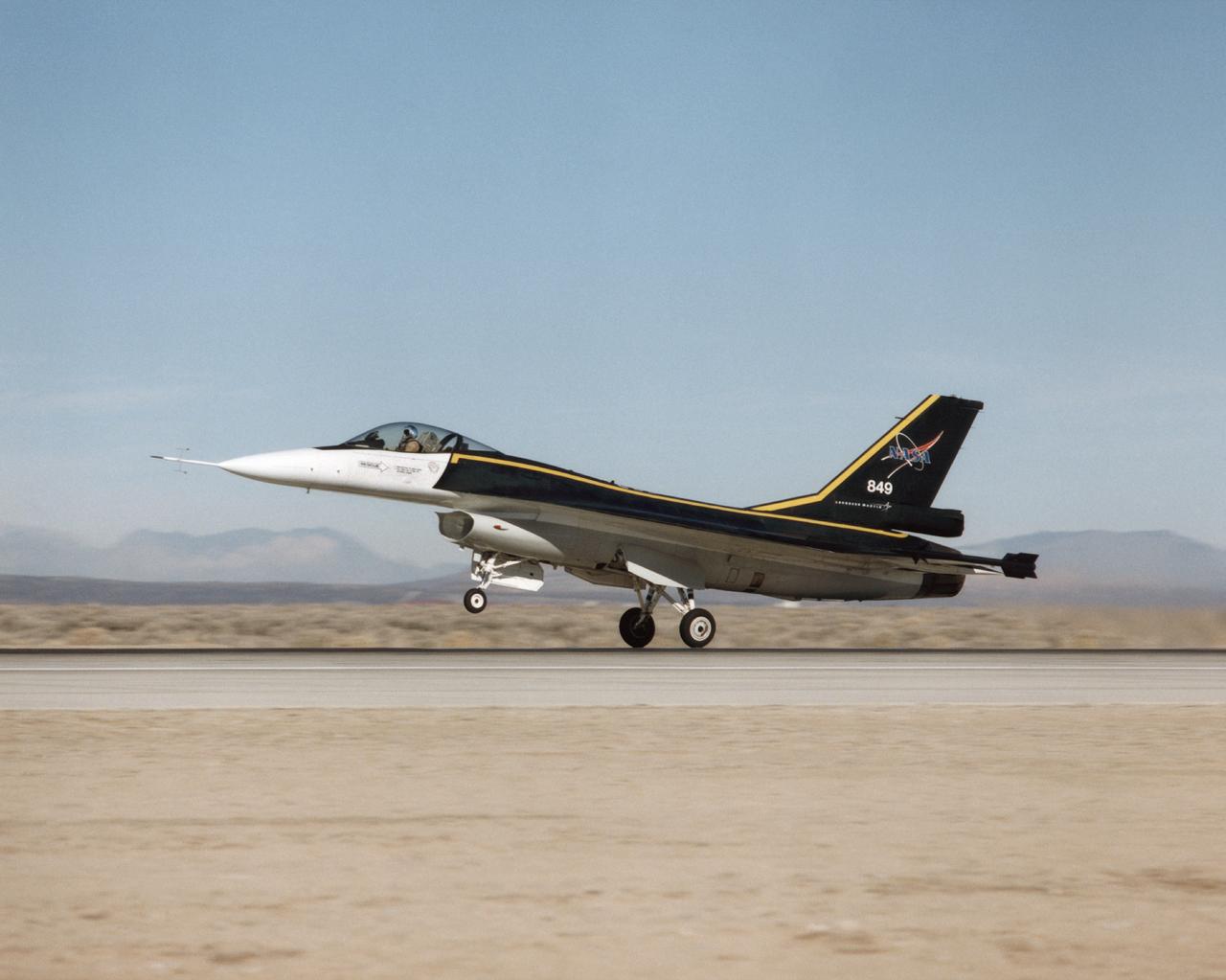
The F-16XL #1 (NASA 849) takes off for the first flight of the Digital Flight Control System (DFCS) on December 16, 1997. Like most first flight, the DFCS required months of preparations. During July 1997, crews worked on the engine, cockpit, canopy, seat, and instrumentation. By late August, the aircraft began combined systems tests and a flight readiness review. Although the Air Force Safety Review Board (AFSRB)- a group that provided double checks on all flight operations - approved the program in late November 1997, a problem with the aircraft flight computer delayed the functional check flight until mid-December.
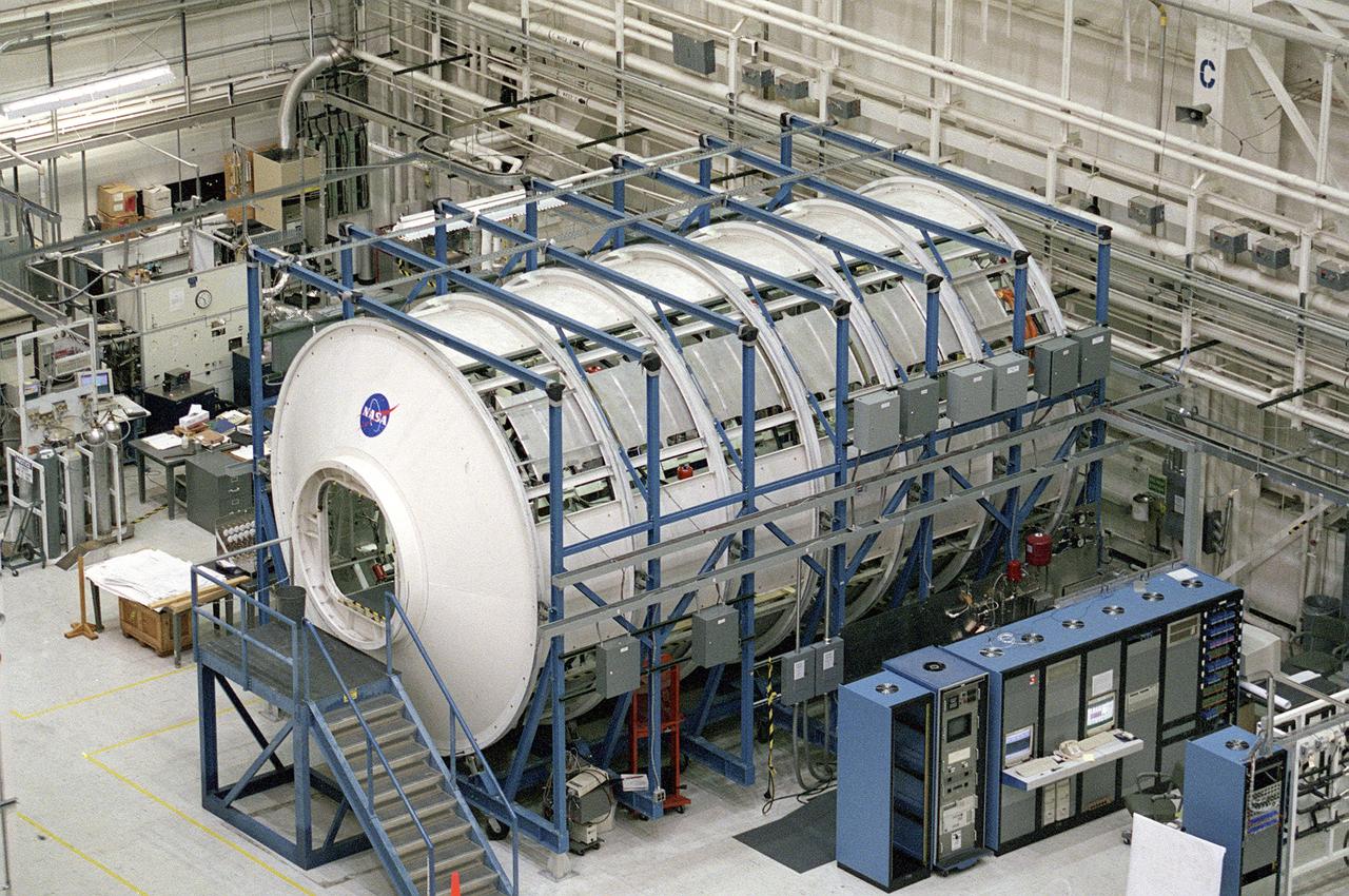
The Marshall Space Flight Center (MSFC) is responsible for designing and building the life support systems that will provide the crew of the International Space Station (ISS) a comfortable environment in which to live and work. Scientists and engineers at the MSFC are working together to provide the ISS with systems that are safe, efficient and cost-effective. These compact and powerful systems are collectively called the Environmental Control and Life Support Systems, or simply, ECLSS. This is an exterior view of the U.S. Laboratory Module Simulator containing the ECLSS Internal Thermal Control System (ITCS) testing facility at MSFC. At the bottom right is the data acquisition and control computers (in the blue equipment racks) that monitor the testing in the facility. The ITCS simulator facility duplicates the function, operation, and troubleshooting problems of the ITCS. The main function of the ITCS is to control the temperature of equipment and hardware installed in a typical ISS Payload Rack.

ISS036-E-025030 (26 July 2013) --- From the International Space Station?s Destiny laboratory, European Space Agency astronaut Luca Parmitano, Expedition 36 flight engineer, uses a computer as he partners with Ames Research Center to remotely control a surface rover in California. The experiment, called Surface Telerobotics, will help scientists plan future missions where a robotic rover could prepare a site on a moon or a planet for a crew.
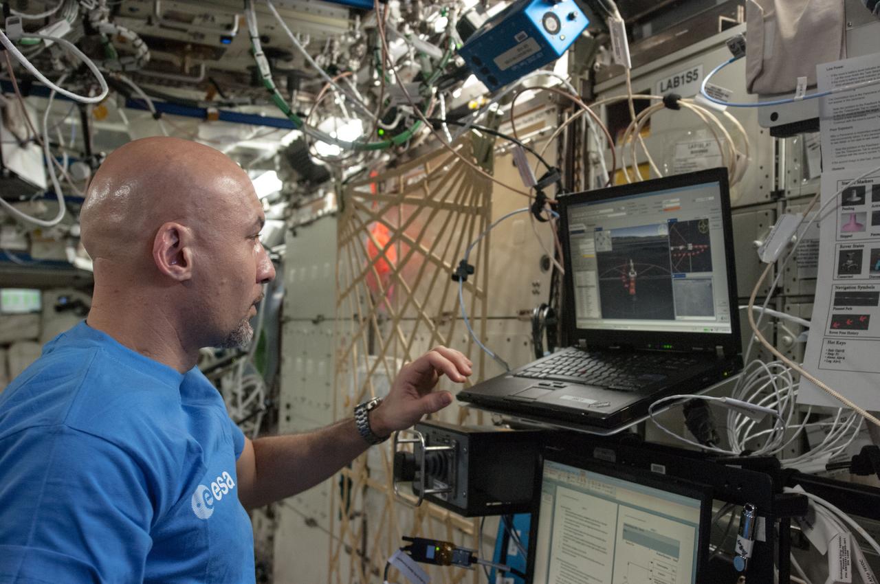
ISS036-E-025012 (26 July 2013) --- From the International Space Station?s Destiny laboratory, European Space Agency astronaut Luca Parmitano, Expedition 36 flight engineer, uses a computer as he partners with Ames Research Center to remotely control a surface rover in California. The experiment, called Surface Telerobotics, will help scientists plan future missions where a robotic rover could prepare a site on a moon or a planet for a crew.
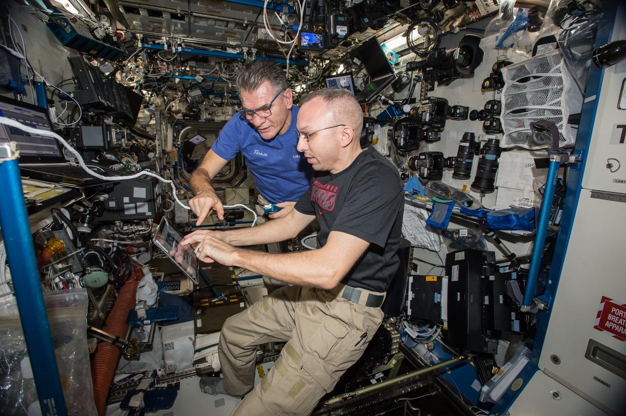
iss053e156180 (Nov. 9, 2017) --- Expedition 53 Commander Randy Bresnik (foreground) and Flight Engineer Paolo Nespoli are at the controls of the robotics workstation in the Destiny laboratory module training for the approach, rendezvous and grapple of the Orbital ATK Cygnus resupply ship. Both astronauts were in the cupola operating the Canadarm2 robotic arm to grapple Cygnus when it arrived Nov. 14, 2017, delivering nearly 7,400 pounds of crew supplies, science experiments, computer gear, vehicle equipment and spacewalk hardware.
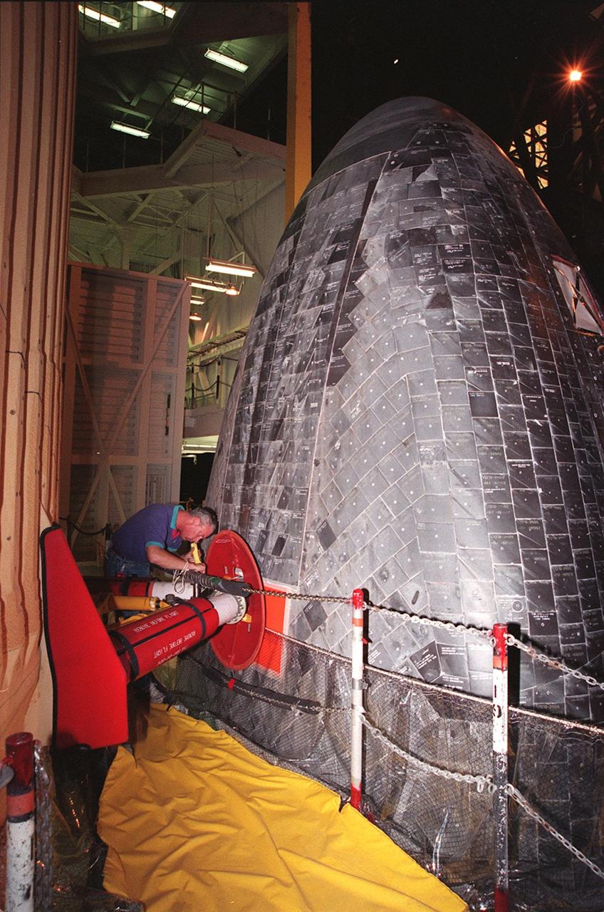
KENNEDY SPACE CENTER, FLA. -- In the Vehicle Assembly Building, Ken Strite, NASA Quality Control, inspects the connection between Space Shuttle Discovery and the external tank that will be used to launch mission STS-103 in early December. This 10-day mission is designed to replace aging parts on the nine-year-old Hubble Space Telescope and to upgrade some of its functioning systems. During the flight, the astronaut crew will replace all six of the observatory's gyroscopes, a fine guidance sensor, its main computer, and other equipment
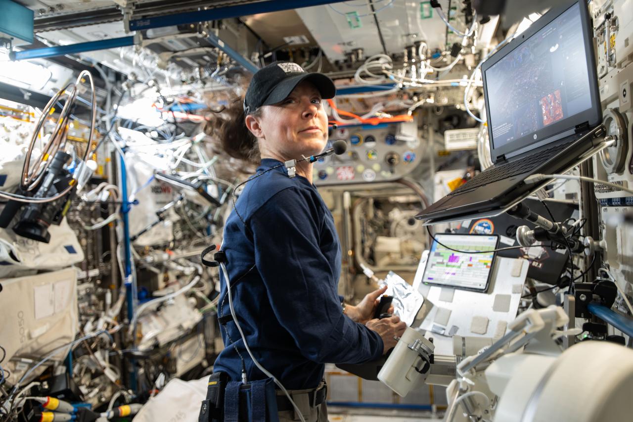
iss071e297582 (July 9, 2024) --- NASA astronaut and Expedition 71 Flight Engineer Tracy C. Dyson is pictured inside the International Space Station's Columbus laboratory module. She was exploring ways to control a robot on the ground from a spacecraft. Dyson coordinated with robotics engineers on Earth remotely manipulating a robot using a computer while testing its ergonomic features and haptic feedback for conditions such as wind and gravity. Results may inform future exploration missions to the Moon, Mars, and beyond.
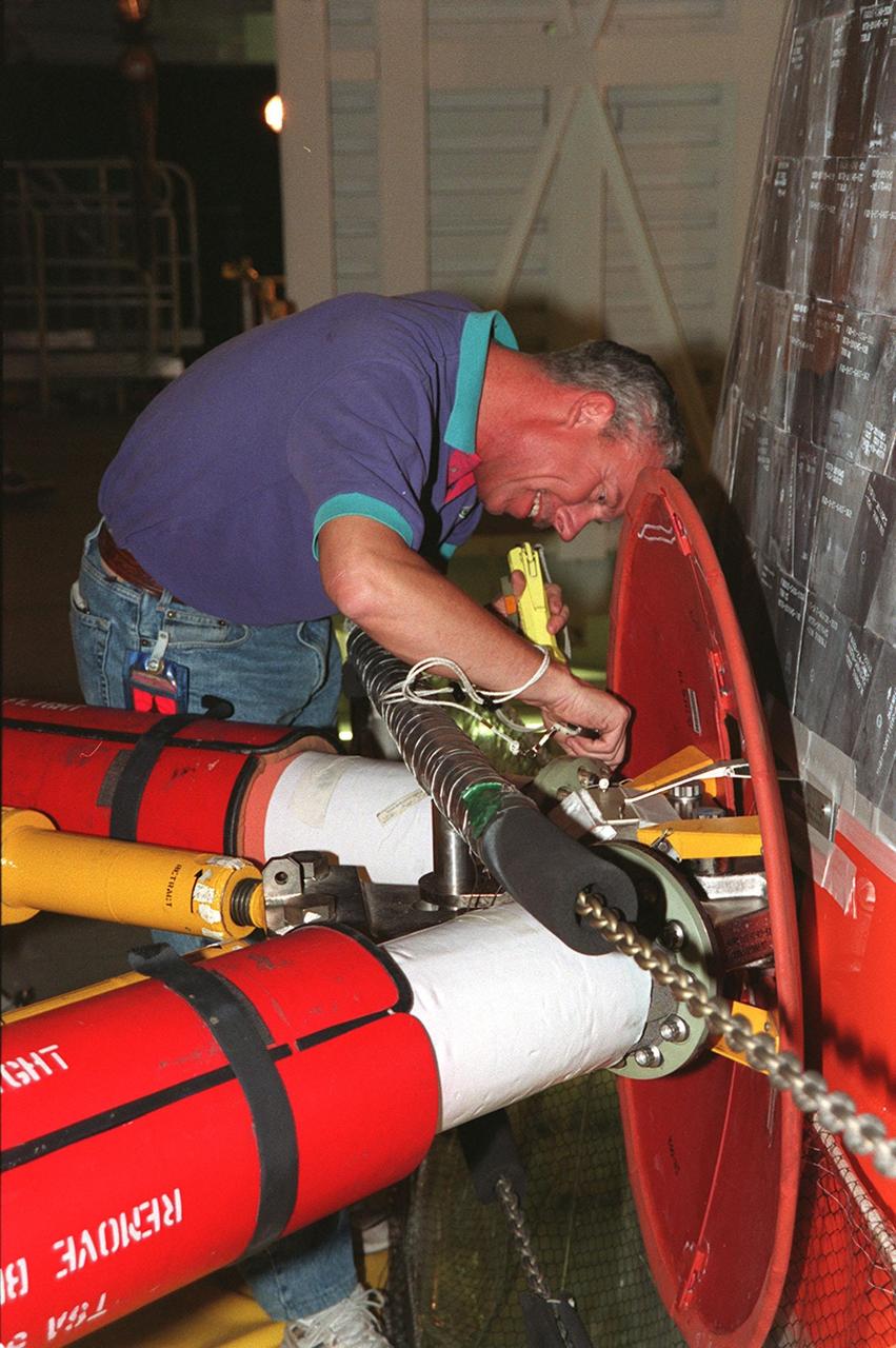
KENNEDY SPACE CENTER, FLA. -- In the Vehicle Assembly Building, Ken Strite, NASA Quality Control, inspects the connection between Space Shuttle Discovery and the external tank that will be used to launch mission STS-103 in early December. This 10-day mission is designed to replace aging parts on the nine-year-old Hubble Space Telescope and to upgrade some of its functioning systems. During the flight, the astronaut crew will replace all six of the observatory's gyroscopes, a fine guidance sensor, its main computer, and other equipment
iss071e318587 (July 10, 2024) --- NASA astronaut and Expedition 71 Flight Engineer Jeanette Epps is pictured inside the International Space Station's Columbus laboratory module. She was exploring ways to control a robot on the ground from a spacecraft. Epps coordinated with robotics engineers on Earth remotely manipulating a robot using a computer while testing its ergonomic features and haptic feedback for conditions such as wind and gravity. Results may inform future exploration missions to the Moon, Mars, and beyond.
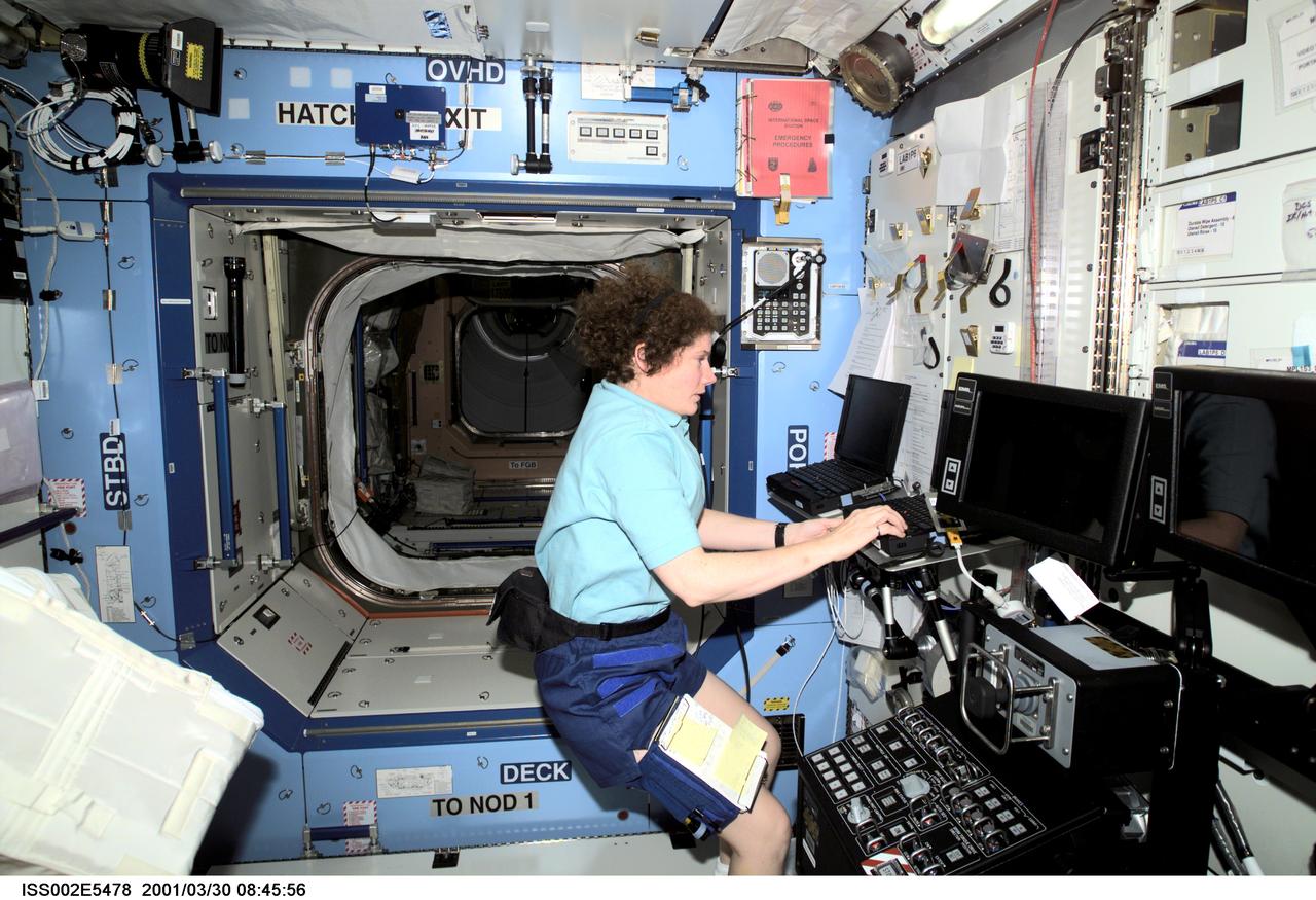
ISS002-E-5478 (30 March 2001) --- Astronaut Susan J. Helms, Expedition Two flight engineer, works at a laptop computer in the U.S. Laboratory / Destiny module of the International Space Station (ISS). The Space Station Remote Manipulator System (SSRMS) control panel is visible to Helms' right. This image was recorded with a digital still camera.
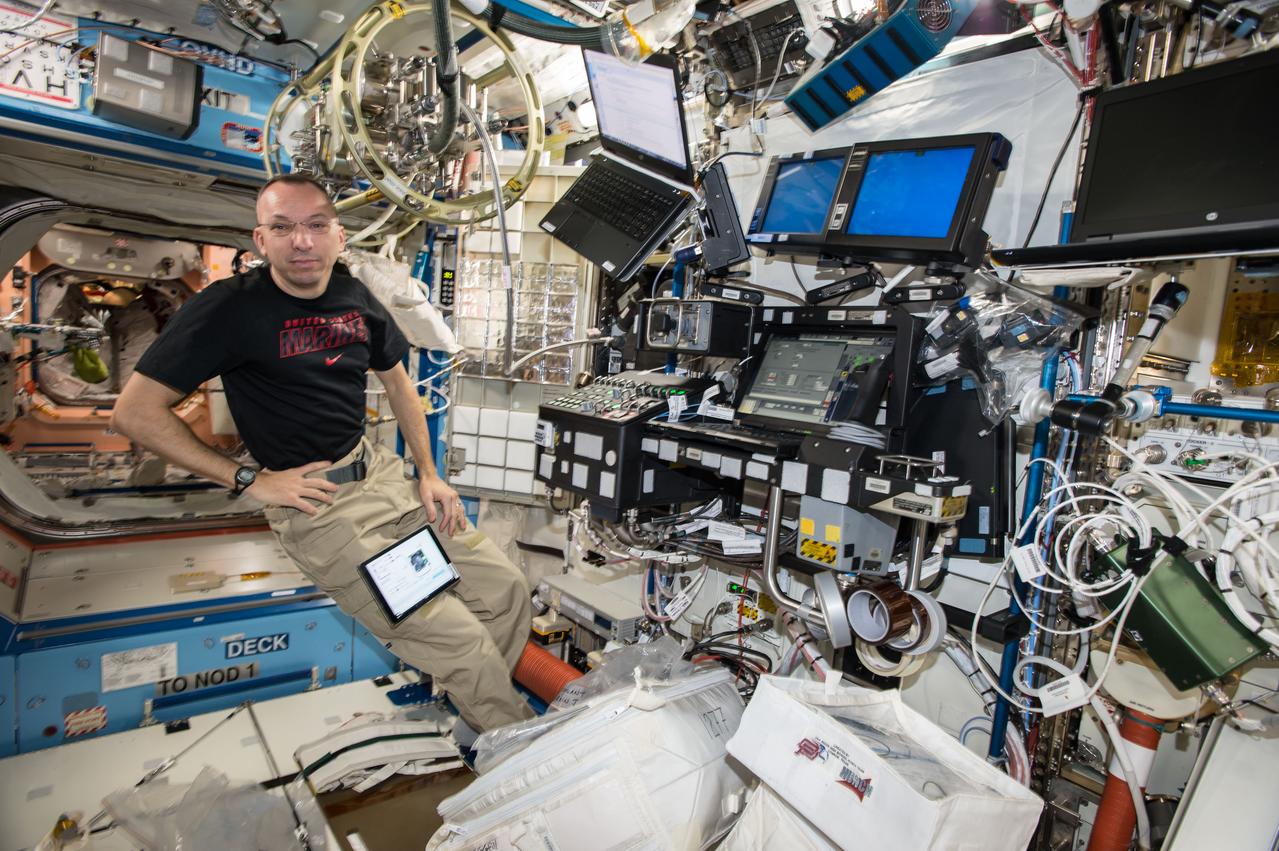
iss053e156160 (Nov. 9, 2017) --- Expedition 53 Commander Randy Bresnik is at the controls of the robotics workstation in the Destiny laboratory module training for the approach, rendezvous and grapple of the Orbital ATK Cygnus resupply ship. He and Flight Engineer Paolo Nespoli were in the cupola operating the Canadarm2 robotic arm to grapple Cygnus when it arrived Nov. 14, 2017, delivering nearly 7,400 pounds of crew supplies, science experiments, computer gear, vehicle equipment and spacewalk hardware.
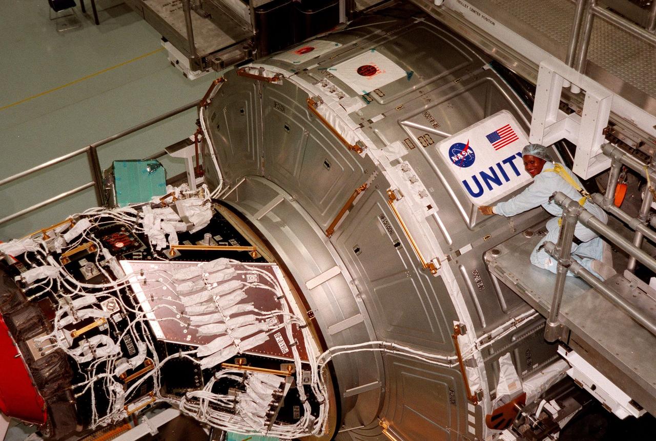
In the Space Station Processing Facility, Joan Higgenbotham, with KSC's Astronaut Office Computer Support, checks placement of the nameplate for the Unity connecting module, part of the International Space Station. Unity was expected to be transported to Launch Pad 39A on Oct. 26 for launch aboard Space Shuttle Endeavour on Mission STS-88 in December. The Unity is a connecting passageway to the living and working areas of ISS. While on orbit, the flight crew will deploy Unity from the payload bay and attach Unity to the Russian-built Zarya control module which will be in orbit at that time
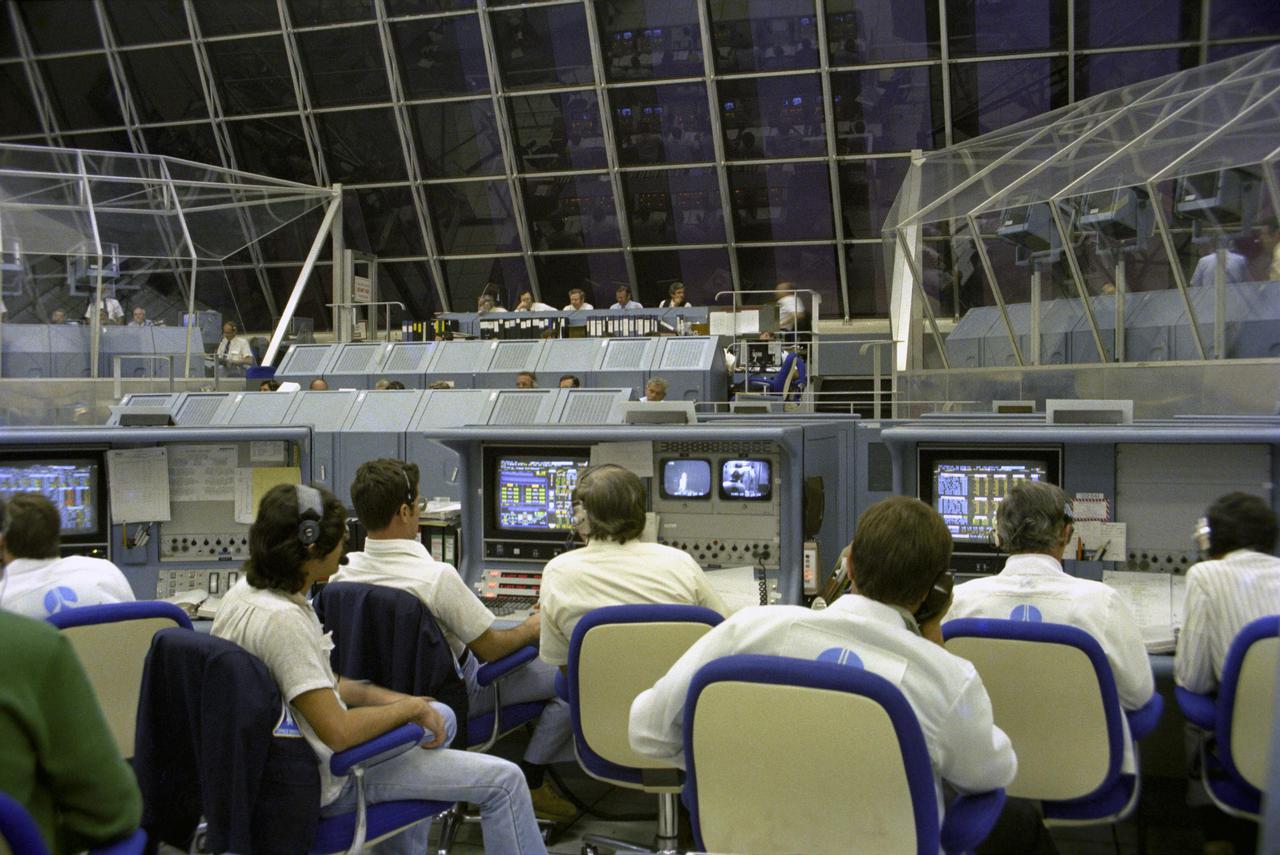
KENNEDY SPACE CENTER, FLA. - Heavy, blast-proof steel louvers seal the large windows of the Launch Control Center’s firing room against mishaps that fail to occur when the first flight of the Space Shuttle is launched from Pad 39A 3.5 mile away. Launch staff, intently watching their computer readouts and TV monitors during the critical moments of launch, will cheer and wave miniature American flags when Astronauts John Young and Robert Crippen complete their fiery rocket ascent safely.
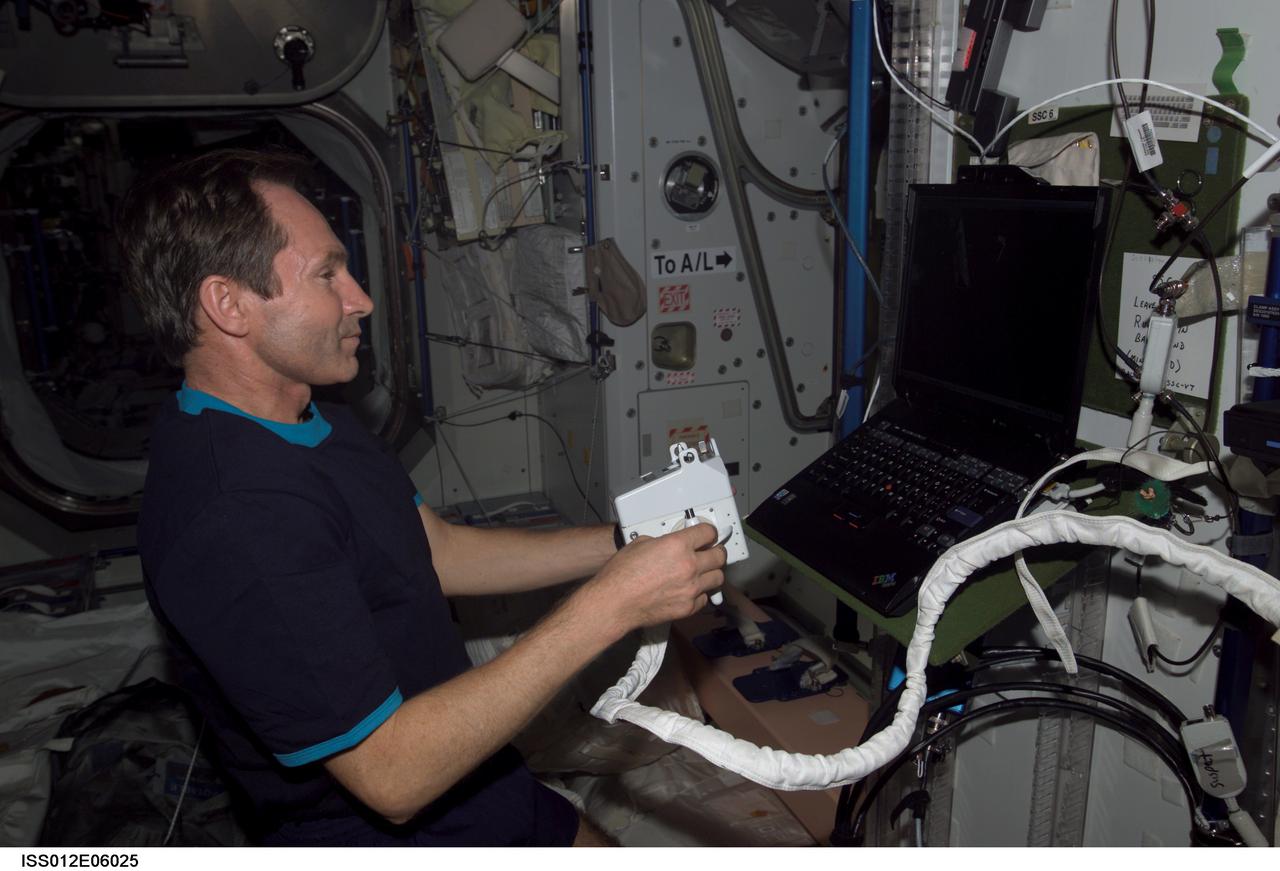
ISS012-E-06025 (21 October 2005) --- Cosmonaut Valery I. Tokarev, Expedition 12 flight engineer representing Russia's Federal Space Agency, holds a Hand Control Module (HCM) while looking at laptop computer graphics during a Simplified Aid for EVA Rescue (SAFER) training session in the Unity node of the international space station.
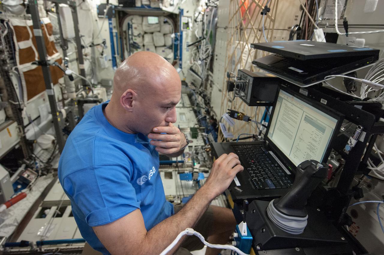
ISS036-E-025034 (26 July 2013) --- From the International Space Station?s Destiny laboratory, European Space Agency astronaut Luca Parmitano, Expedition 36 flight engineer, uses a computer as he partners with Ames Research Center to remotely control a surface rover in California. The experiment, called Surface Telerobotics, will help scientists plan future missions where a robotic rover could prepare a site on a moon or a planet for a crew.
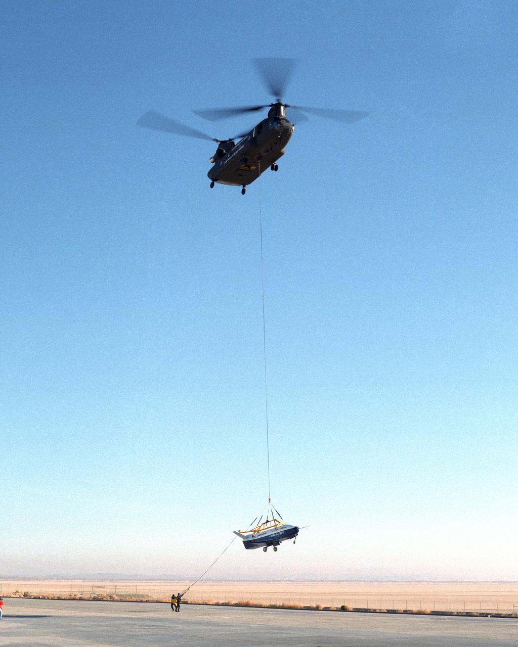
Ground crewmen help guide the alignment of the X-40 technology demonstrator as the experimental craft is gently lowered to the ground by a U.S. Army CH-47 Chinook cargo helicopter following a captive-carry test flight at NASA's Dryden Flight Research Center, Edwards, California. The X-40 is an unpowered 82 percent scale version of the X-37, a Boeing-developed spaceplane designed to demonstrate various advanced technologies for development of future lower-cost access to space vehicles. The X-37 will be carried into space aboard a space shuttle and then released to perform various maneuvers and a controlled re-entry through the Earth's atmosphere to an airplane-style landing on a runway, controlled entirely by pre-programmed computer software. Following a series of captive-carry flights, the X-40 made several free flights from a launch altitude of about 15,000 feet above ground, gliding to a fully autonomous landing. The captive carry flights helped verify the X-40's navigation and control systems, rigging angles for its sling, and stability and control of the helicopter while carrying the X-40 on a tether.
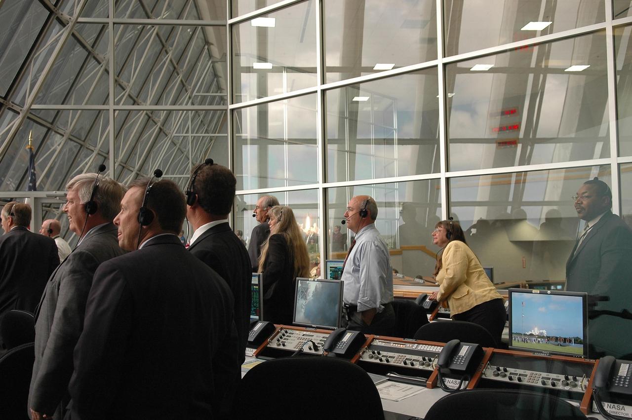
KENNEDY SPACE CENTER, FLA. - Inside the Launch Control Center, NASA and KSC officials turn from their computers to watch through the broad windows the launch of Space Shuttle Atlantis on mission STS-115. Second from left is Kennedy Space Center Director Jim Kennedy. Mission STS-115 is the 116th space shuttle flight, the 27th flight for orbiter Atlantis, and the 19th U.S. flight to the International Space Station. STS-115 is scheduled to last 11 days with a planned landing at KSC. Photo credit: NASA/Kim Shiflett
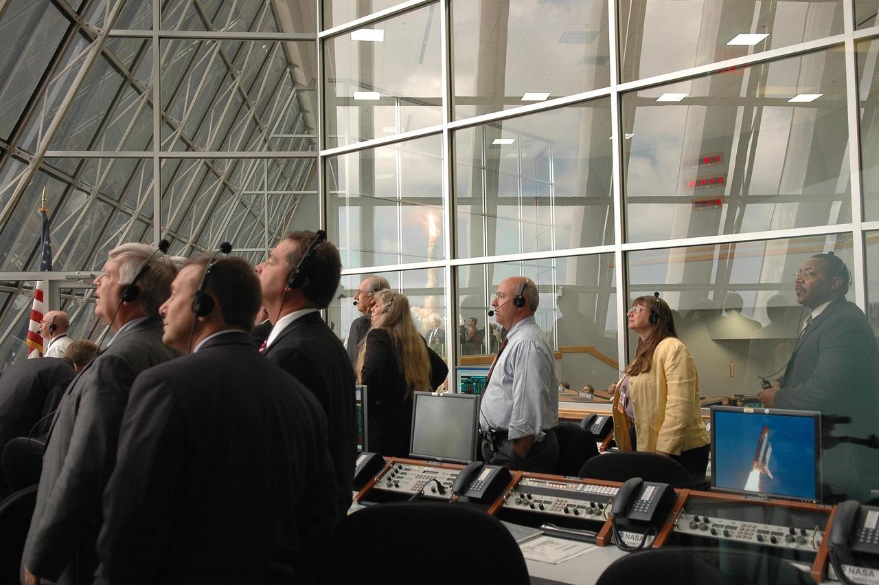
KENNEDY SPACE CENTER, FLA. - Inside the Launch Control Center, NASA and KSC officials turn from their computers to watch through the broad windows the launch of Space Shuttle Atlantis on mission STS-115. Second from left is Kennedy Space Center Director Jim Kennedy. Mission STS-115 is the 116th space shuttle flight, the 27th flight for orbiter Atlantis, and the 19th U.S. flight to the International Space Station. STS-115 is scheduled to last 11 days with a planned landing at KSC. Photo credit: NASA/Kim Shiflett
STS064-311-033 (10 Sept. 1994) --- Half of the crew members share support of the Shuttle Plume Impingement Flight Experiment (SPIFEX) in this 35mm frame. Astronauts Susan J. Helms and Mark C. Lee (foreground) share a pertinent bit of data while astronaut L. Blaine Hammond in the background controls Reaction Control System (RCS) thrusters on the space shuttle Discovery. Helms' role was to control the Remote Manipulator System (RMS) arm, to which 30-feet of SPIFEX hardware were appended in order to measure the RCS plume induced loads in the far field region. Lee records data on a lap top Payload General Support Computer (PGSC). SPIFEX was developed to help understand the thruster effects on approaching spacecraft. Photo credit: NASA or National Aeronautics and Space Administration
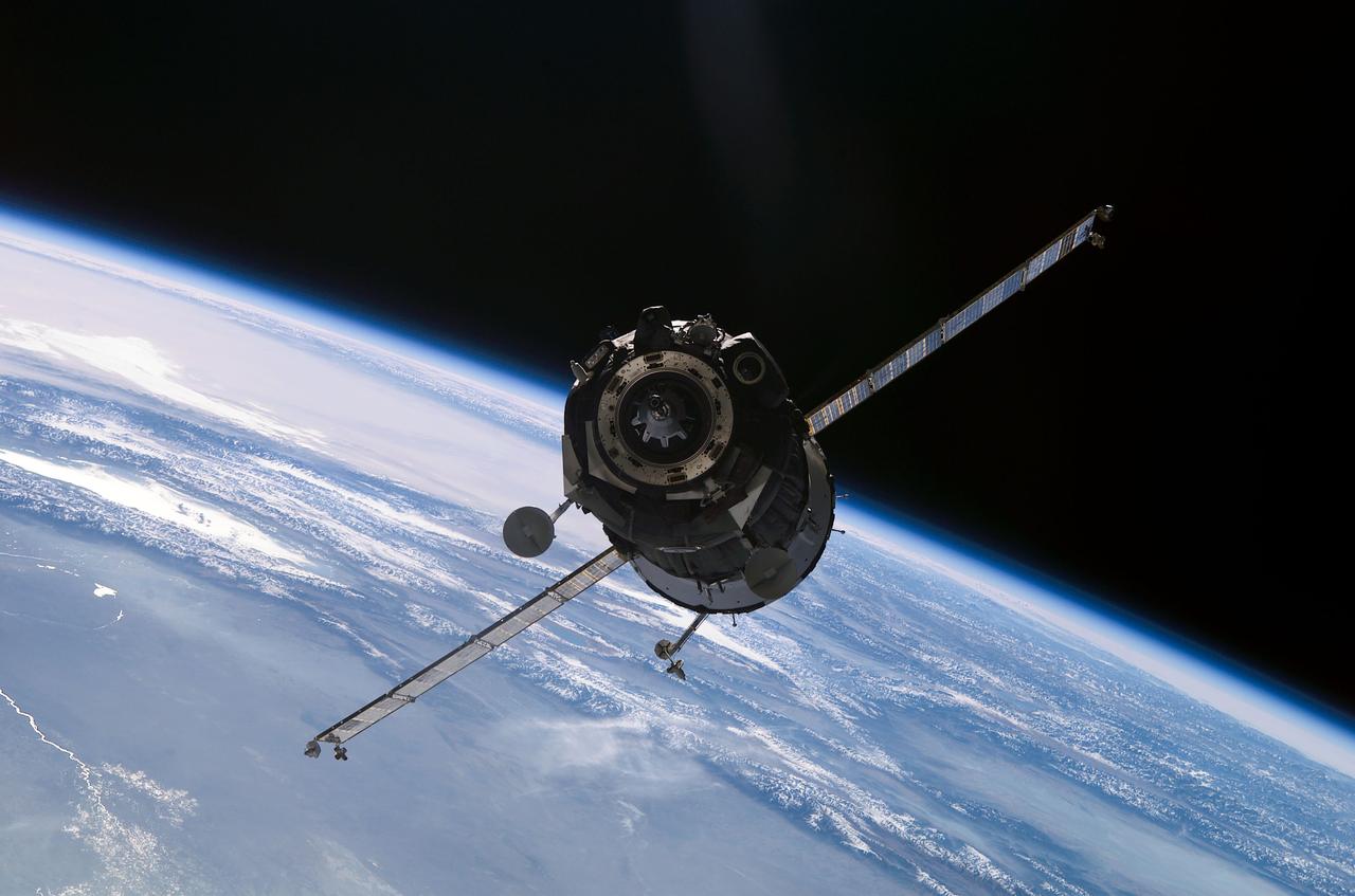
ISS005-E-19267 (1 November 2002) --- A Soyuz spacecraft approaches the Pirs docking compartment on the International Space Station (ISS) carrying the Soyuz 5 taxi crew, Commander Sergei Zalyotin, Belgian Flight Engineer Frank DeWinne, and Flight Engineer Yuri V. Lonchakov for an eight-day stay on the station. The new Soyuz TMA-1 vehicle was designed to accommodate larger or smaller crewmembers, and is equipped with upgraded computers, a new cockpit control panel and improved avionics. Zalyotin and Lonchakov represent Rosaviakosmos and DeWinne represents the European Space Agency (ESA). The blackness of space and Earth’s horizon provide the backdrop for the scene.
Mission control Blue Room, seen here, in building 4800 at NASA's Dryden Flight Research Center, is part of the Western Aeronautical Test Range (WATR). All aspects of a research mission are monitored from one of two of these control rooms at Dryden. The WATR consists of a highly automated complex of computer controlled tracking, telemetry, and communications systems and control room complexes that are capable of supporting any type of mission ranging from system and component testing, to sub-scale and full-scale flight tests of new aircraft and reentry systems. Designated areas are assigned for spin/dive tests, corridors are provided for low, medium, and high-altitude supersonic flight, and special STOL/VSTOL facilities are available at Ames Moffett and Crows Landing. Special use airspace, available at Edwards, covers approximately twelve thousand square miles of mostly desert area. The southern boundary lies to the south of Rogers Dry Lake, the western boundary lies midway between Mojave and Bakersfield, the northern boundary passes just south of Bishop, and the eastern boundary follows about 25 miles west of the Nevada border except in the northern areas where it crosses into Nevada.
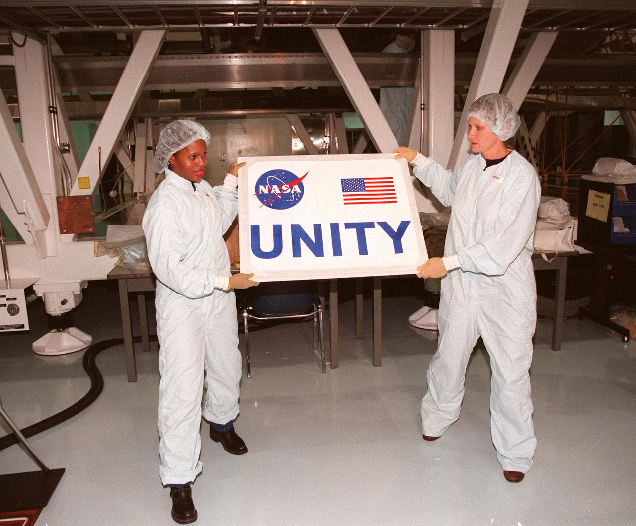
In the Space Station Processing Facility, holding the nameplate for the Unity connecting module are (left) Joan Higginbotham, with the Astronaut Office Computer Support Branch, and (right) Nancy Tolliver, with Boeing-Huntsville. Part of the International Space Station, Unity was expected to be transported to Launch Pad 39A on Oct. 26 for launch aboard Space Shuttle Endeavour on Mission STS-88 in December. The Unity is a connecting passageway to the living and working areas of ISS. While on orbit, the flight crew will deploy Unity from the payload bay and attach Unity to the Russian-built Zarya control module which will be in orbit at that time
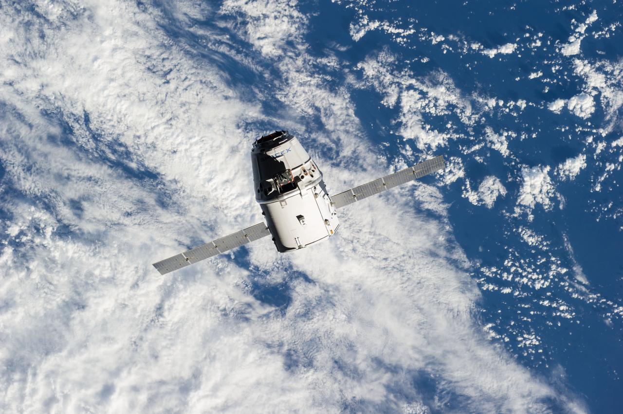
ISS041-E-020833 (23 Sept. 2014) --- The SpaceX Dragon commercial cargo craft approaches the International Space Station on Sept. 23, 2014 for grapple and berthing. European Space Agency astronaut Alexander Gerst and NASA astronaut Reid Wiseman, both Expedition 41 flight engineers, were at the controls of the robotics workstation in the Cupola when the Canadarm2 grappled Dragon at 6:52 a.m. (EDT). Dragon will spend the next four weeks attached to the Harmony node as the Expedition 41 crew unloads 4,885 pounds of (2,216 kg) crew supplies, hardware, experiments, and computer gear and spacewalk equipment.
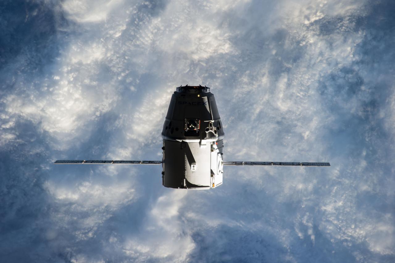
ISS041-E-020800 (23 Sept. 2014) --- The SpaceX Dragon commercial cargo craft approaches the International Space Station on Sept. 23, 2014 for grapple and berthing. European Space Agency astronaut Alexander Gerst and NASA astronaut Reid Wiseman, both Expedition 41 flight engineers, were at the controls of the robotics workstation in the Cupola when the Canadarm2 grappled Dragon at 6:52 a.m. (EDT). Dragon will spend the next four weeks attached to the Harmony node as the Expedition 41 crew unloads 4,885 pounds of (2,216 kg) crew supplies, hardware, experiments, and computer gear and spacewalk equipment.
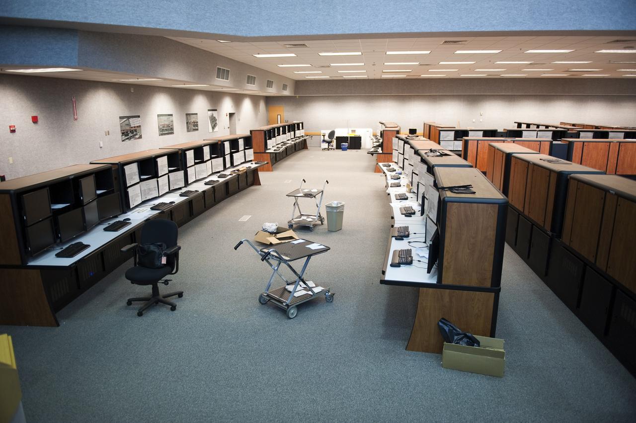
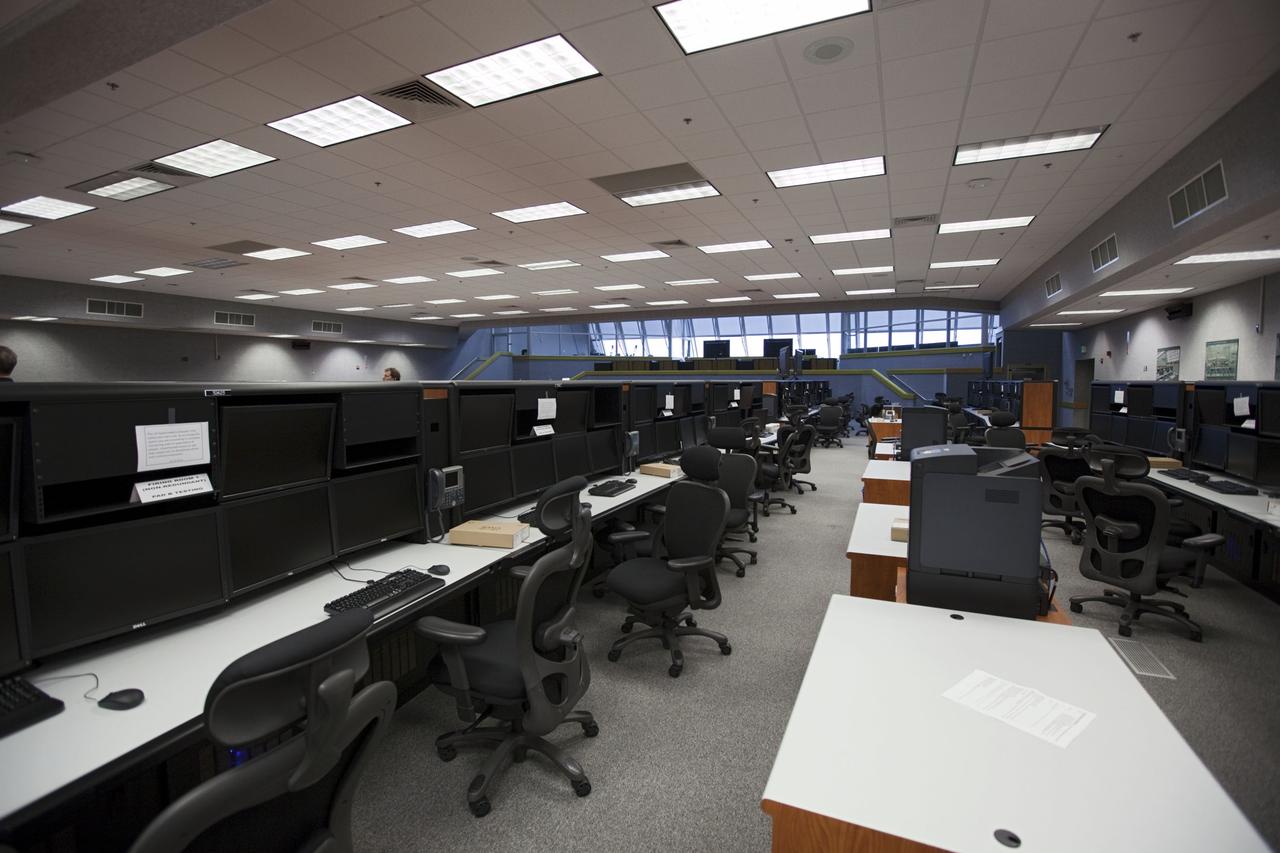
CAPE CANAVERAL, Fla. -- At NASA's Kennedy Space Center in Florida, remodeling for launches of future human spaceflight vehicles continues in the Launch Control Center's Young-Crippen Firing Room. Consoles already have been rewired for the comprehensive upgrade and are now being outfitted with new computers and monitors. Known as Firing Room 1 in the Apollo era, it was re-named as a tribute to the Space Shuttle Program's first crewed mission, STS-1, which was flown by Commander John Young and Pilot Robert Crippen in April 1981. The firing room most recently was set up to support the Ares I-X flight test in Oct. 2009. Photo credit: NASA/Kim Shiflett
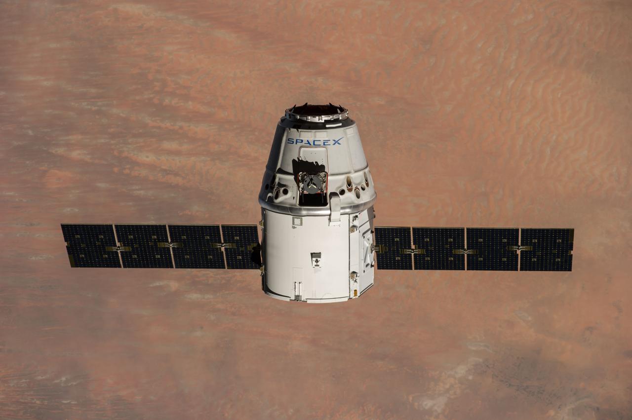
ISS041-E-020882 (23 Sept. 2014) --- The SpaceX Dragon commercial cargo craft approaches the International Space Station on Sept. 23, 2014 for grapple and berthing. European Space Agency astronaut Alexander Gerst and NASA astronaut Reid Wiseman, both Expedition 41 flight engineers, were at the controls of the robotics workstation in the Cupola when the Canadarm2 grappled Dragon at 6:52 a.m. (EDT). Dragon will spend the next four weeks attached to the Harmony node as the Expedition 41 crew unloads 4,885 pounds of (2,216 kg) crew supplies, hardware, experiments, and computer gear and spacewalk equipment.
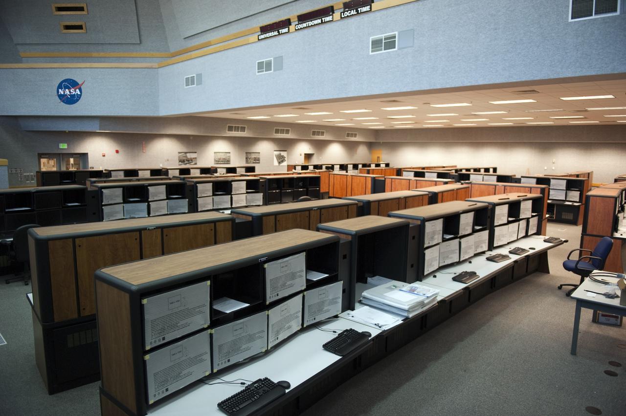
CAPE CANAVERAL, Fla. -- At NASA's Kennedy Space Center in Florida, remodeling for launches of future human spaceflight vehicles continues in the Launch Control Center's Young-Crippen Firing Room. Consoles already have been rewired for the comprehensive upgrade and are now being outfitted with new computers and monitors. Known as Firing Room 1 in the Apollo era, it was re-named as a tribute to the Space Shuttle Program's first crewed mission, STS-1, which was flown by Commander John Young and Pilot Robert Crippen in April 1981. The firing room most recently was set up to support the Ares I-X flight test in Oct. 2009. Photo credit: NASA/Kim Shiflett
CAPE CANAVERAL, Fla. -- At NASA's Kennedy Space Center in Florida, remodeling for launches of future human spaceflight vehicles continues in the Launch Control Center's Young-Crippen Firing Room. Consoles already have been rewired for the comprehensive upgrade and are now being outfitted with new computers and monitors. Known as Firing Room 1 in the Apollo era, it was re-named as a tribute to the Space Shuttle Program's first crewed mission, STS-1, which was flown by Commander John Young and Pilot Robert Crippen in April 1981. The firing room most recently was set up to support the Ares I-X flight test in Oct. 2009. Photo credit: NASA/Kim Shiflett
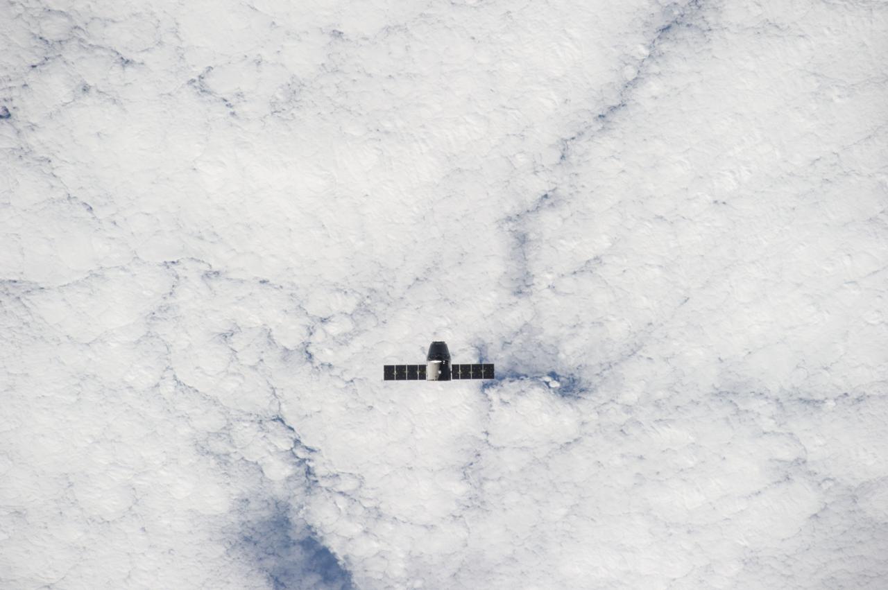
ISS041-E-020655 (23 Sept. 2014) --- The SpaceX Dragon commercial cargo craft approaches the International Space Station on Sept. 23, 2014 for grapple and berthing. European Space Agency astronaut Alexander Gerst and NASA astronaut Reid Wiseman, both Expedition 41 flight engineers, were at the controls of the robotics workstation in the Cupola when the Canadarm2 grappled Dragon at 6:52 a.m. (EDT). Dragon will spend the next four weeks attached to the Harmony node as the Expedition 41 crew unloads 4,885 pounds of (2,216 kg) crew supplies, hardware, experiments, and computer gear and spacewalk equipment.

ISS041-E-020857 (23 Sept. 2014) --- The SpaceX Dragon commercial cargo craft approaches the International Space Station on Sept. 23, 2014 for grapple and berthing. European Space Agency astronaut Alexander Gerst and NASA astronaut Reid Wiseman, both Expedition 41 flight engineers, were at the controls of the robotics workstation in the Cupola when the Canadarm2 grappled Dragon at 6:52 a.m. (EDT). Dragon will spend the next four weeks attached to the Harmony node as the Expedition 41 crew unloads 4,885 pounds of (2,216 kg) crew supplies, hardware, experiments, and computer gear and spacewalk equipment.