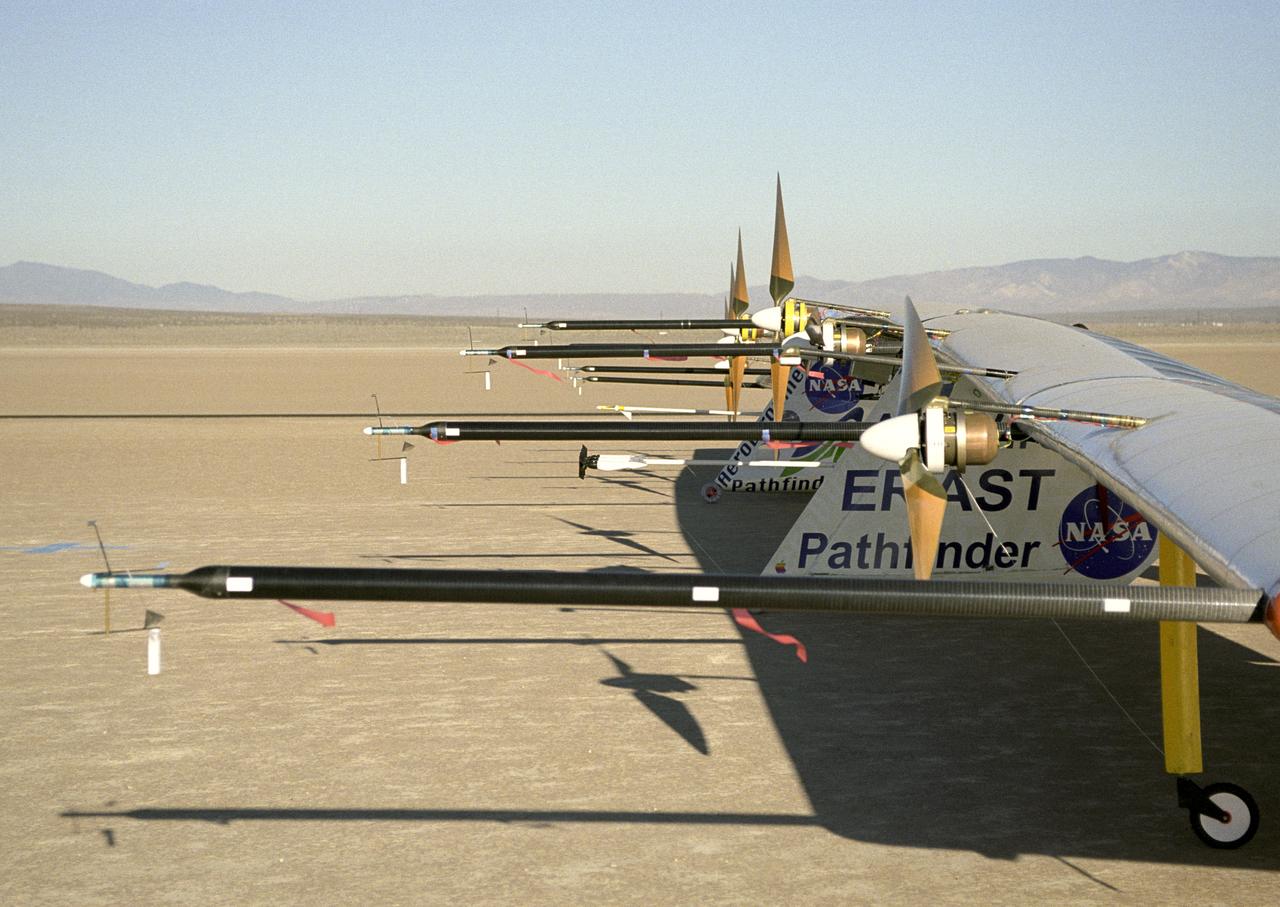
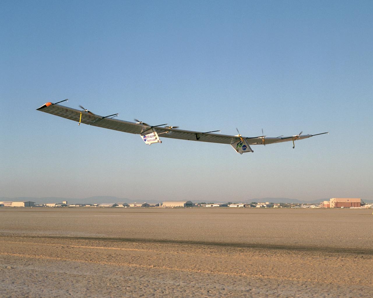
Sensitive instruments mounted on booms extending forward of the wing measure air turbulence and its effect on the stability of the Pathfinder-Plus solar-electric flying wing.
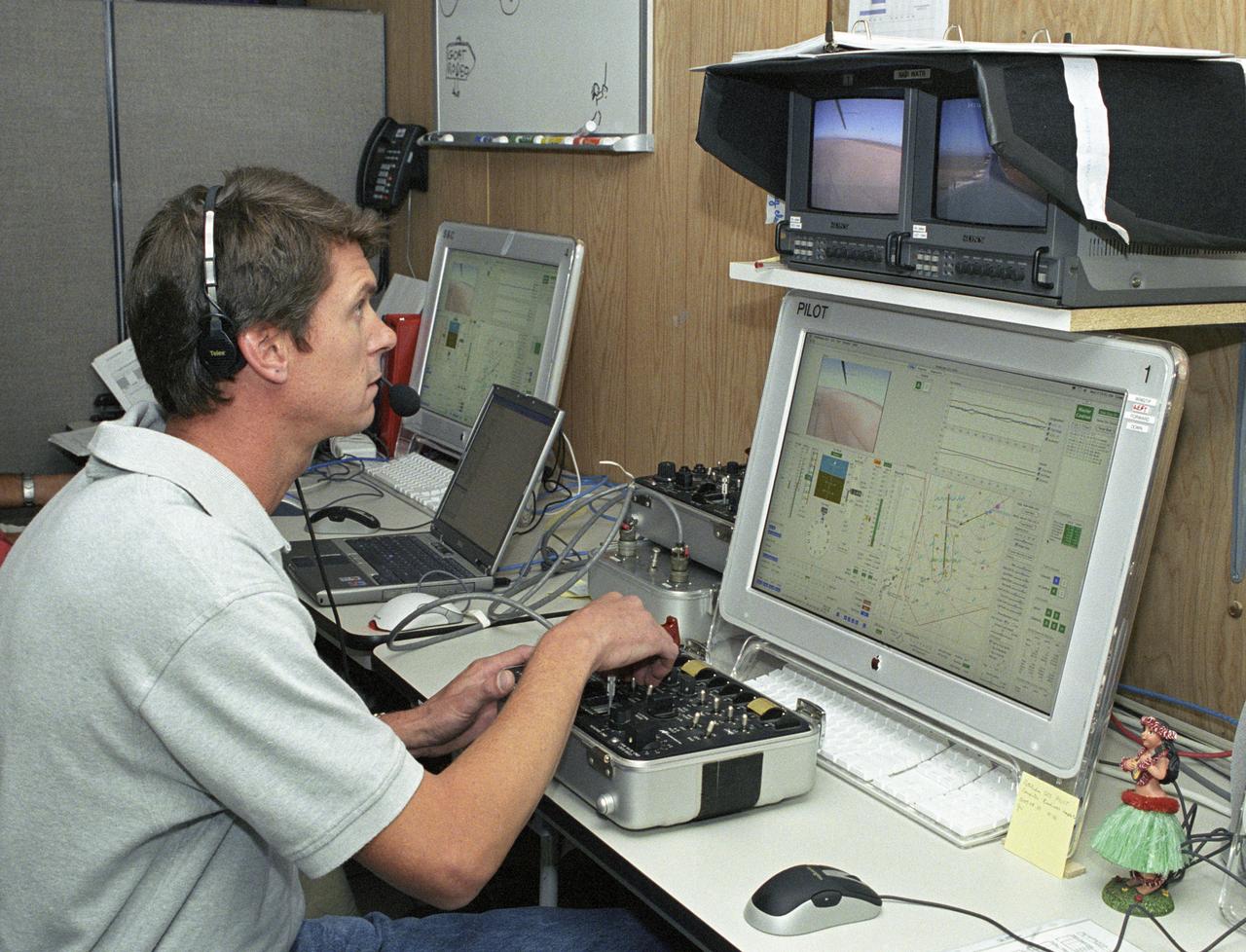
AeroVironment pilot Wyatt Sadler controls the Pathfinder-Plus flying wing from a small console, video and computer monitors in the ground station.
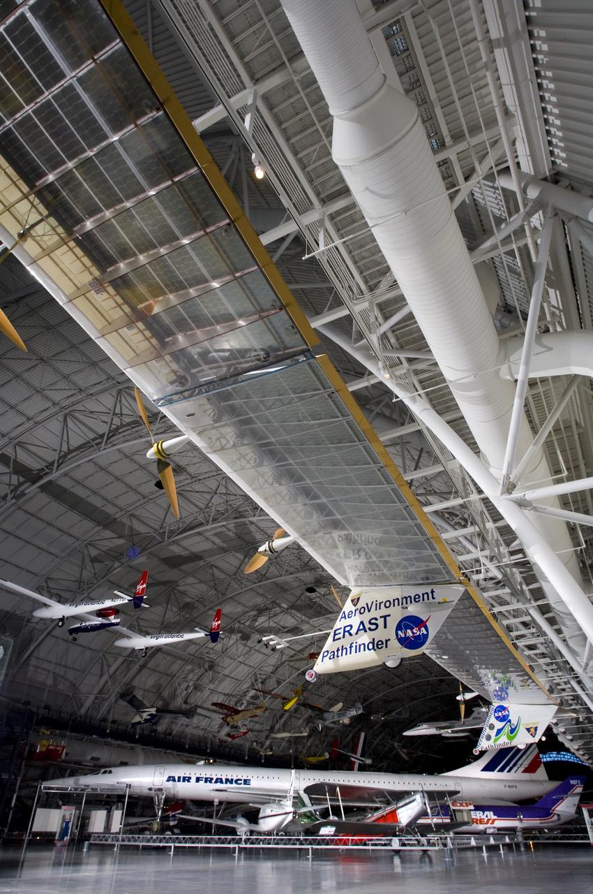
The record-setting AeroVironment/NASA Pathfinder-Plus solar-electric flying wing is enshrined in the National Air & Space Museum's Udvar-Hazy Center in Virginia.
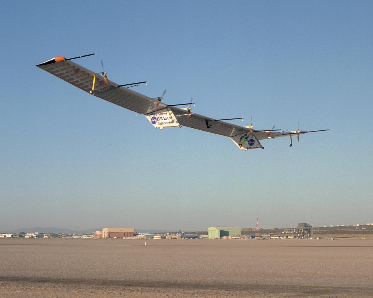
The Pathfinder-Plus solar-electric flying wing lifts off Rogers Dry Lake adjoining NASA Dryden Flight Research Center on a turbulence-measurement flight.
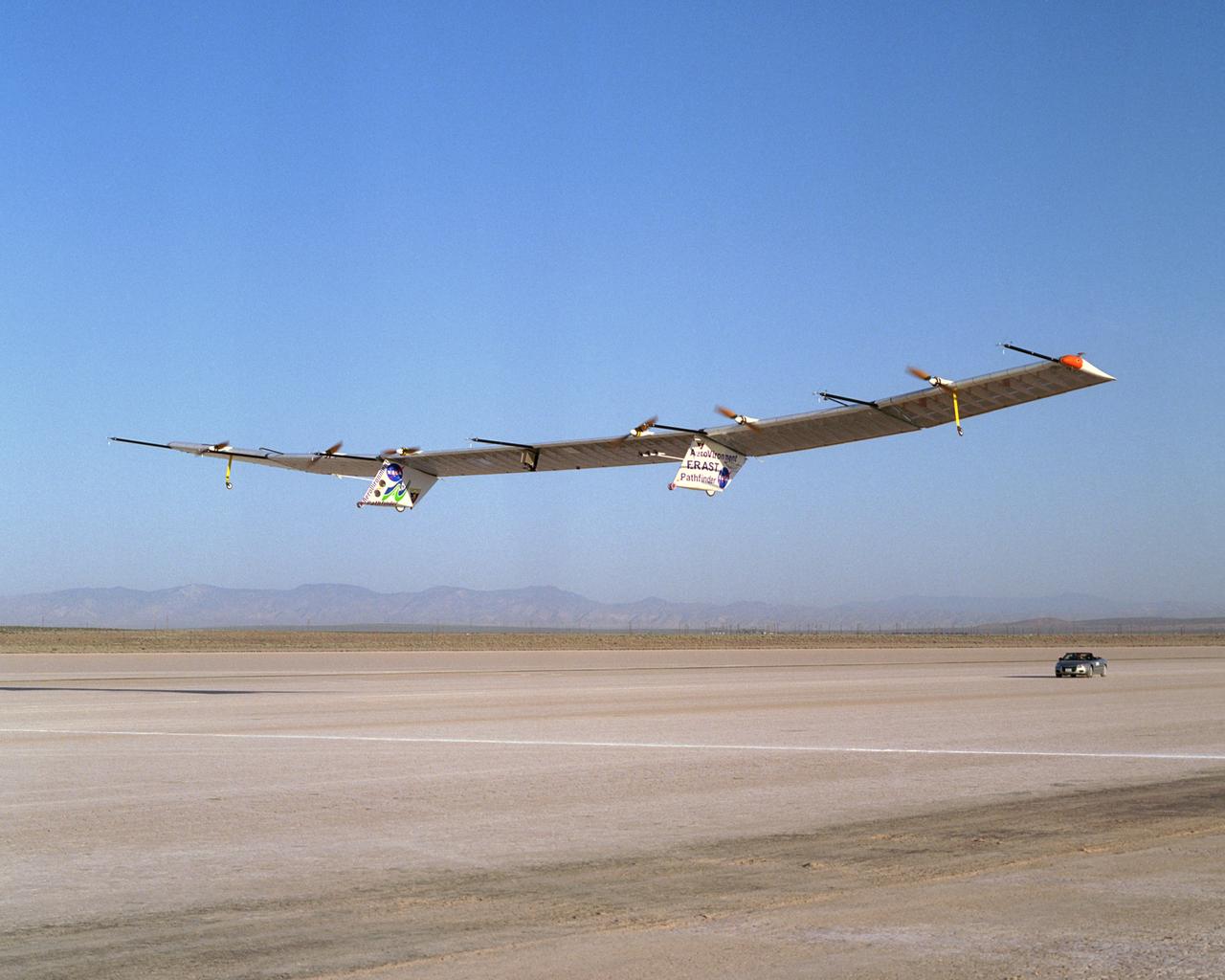
The Pathfinder-Plus solar-electric flying wing lifts off Rogers Dry Lake adjoining NASA Dryden Flight Research Center on a turbulence-measurement flight.
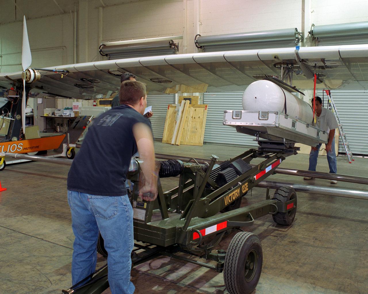
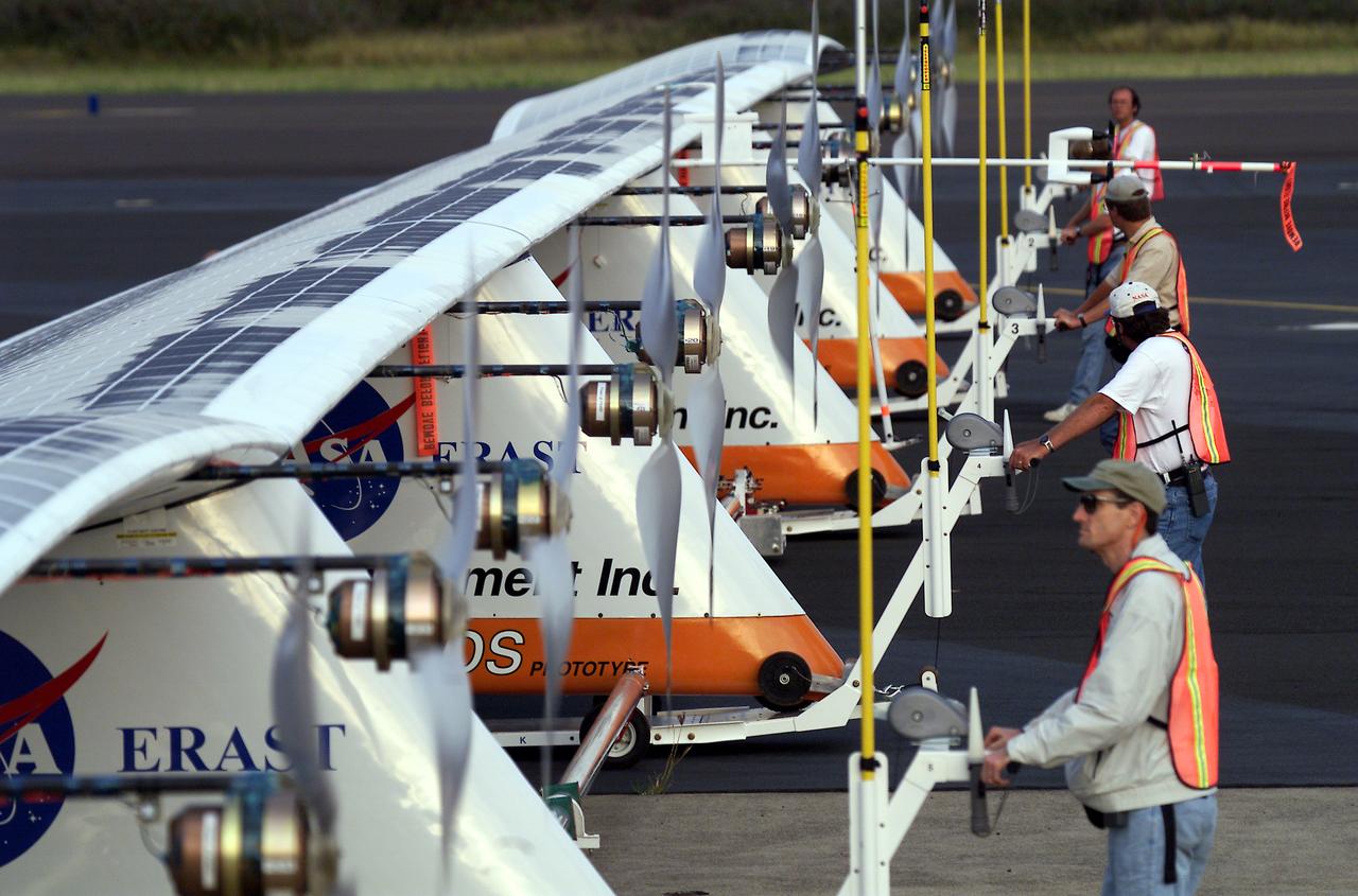
Technicians for AeroVironment, Inc., jack up a pressure tank to the wing of the Helios Prototype solar-electric flying wing. The tank carries pressurized hydrogen to fuel an experimental fuel cell system that powered the aircraft at night during an almost two-day long-endurance flight demonstration in the summer of 2003.
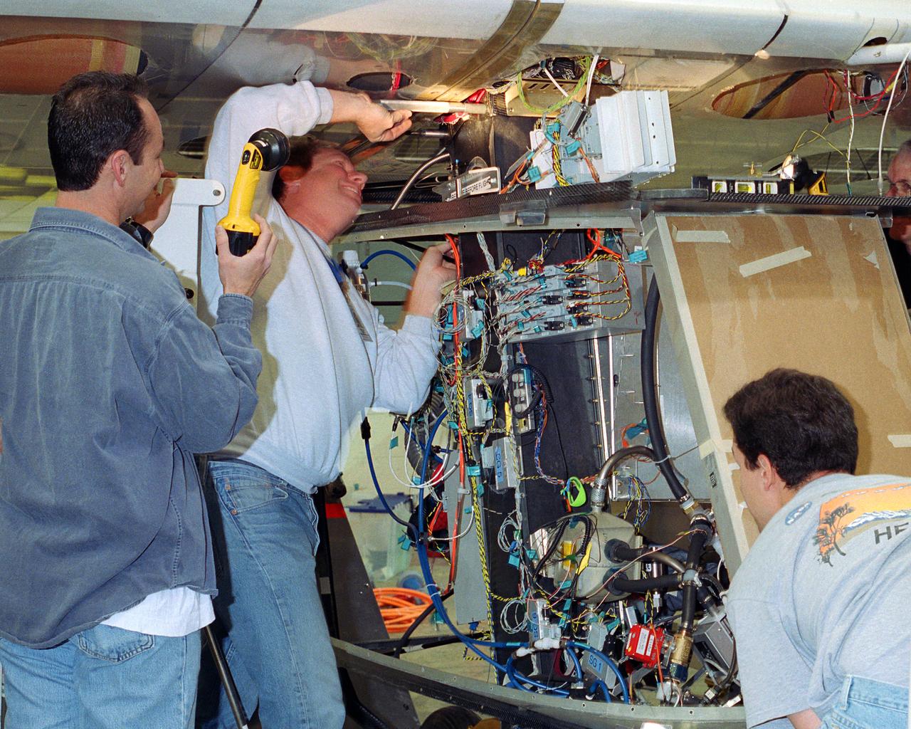
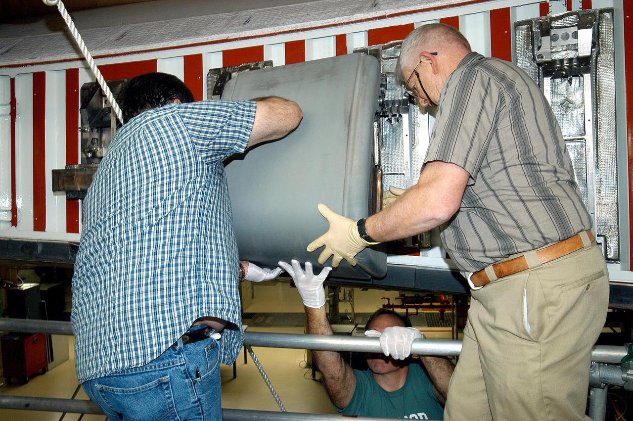
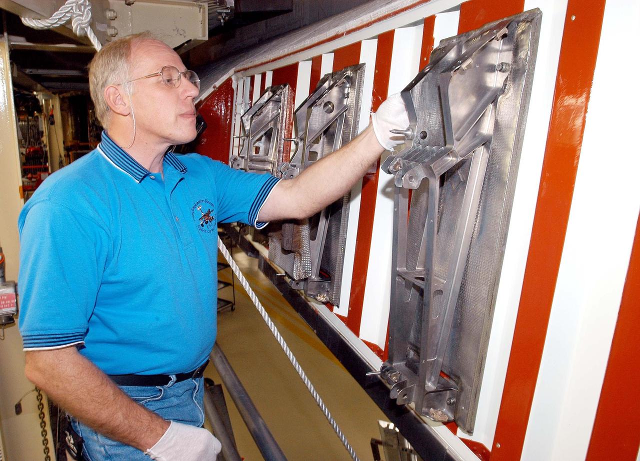
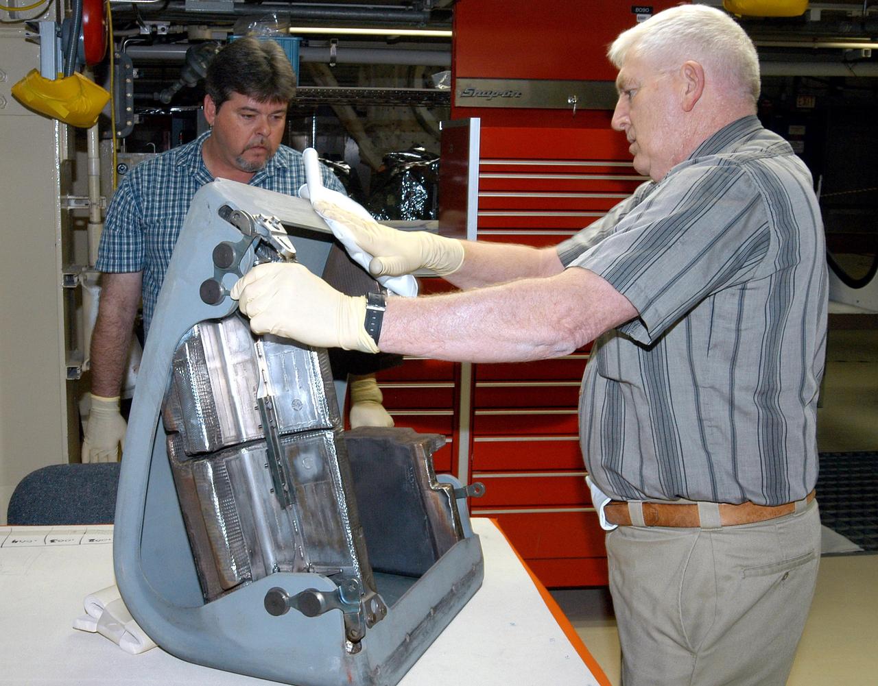
Aerovironment technicians carefully line up attachments as a fuel cell electrical system is installed on the Helios Prototype solar powered flying wing. The fuel cell system will power the aircraft at night during NASA-sponsored long-endurance demonstration flight in the summer of 2003.
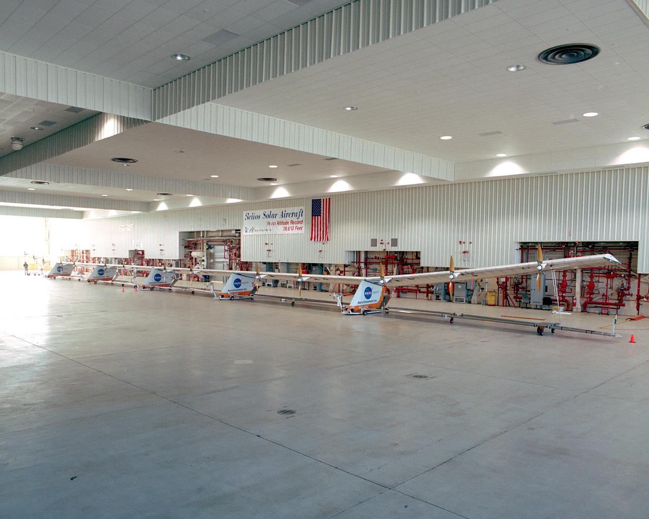
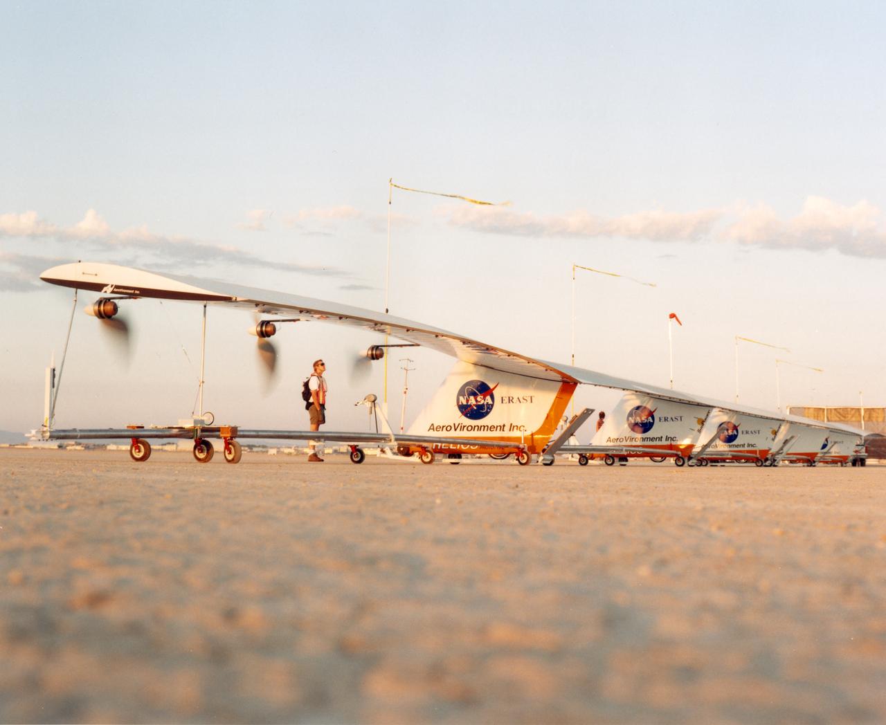
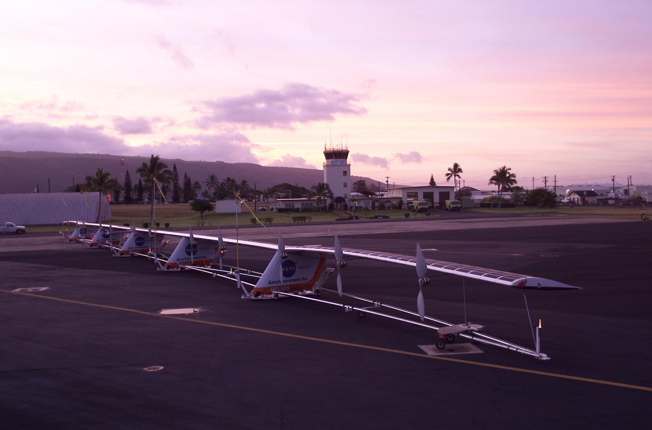
The Helios Prototype flying wing stretches almost the full length of the 300-foot-long hangar at NASA's Dryden Flight Research Center, Edwards, California. The 247-foot span solar-powered aircraft, resting on its ground maneuvering dolly, was on display for a visit of NASA Administrator Sean O'Keefe and other NASA officials on January 31, 2002. The unique solar-electric flying wing reached an altitude of 96,863 feet during an almost 17-hour flight near Hawaii on August 13, 2001, a world record for sustained horizontal flight by a non-rocket powered aircraft. Developed by AeroVironment, Inc., under NASA's Environmental Research Aircraft and Sensor Technology (ERAST) project, the Helios Prototype is the forerunner of a planned fleet of slow-flying, long duration, high-altitude uninhabited aerial vehicles (UAV) which can serve as "atmospheric satellites," performing Earth science missions or functioning as telecommunications relay platforms in the stratosphere.
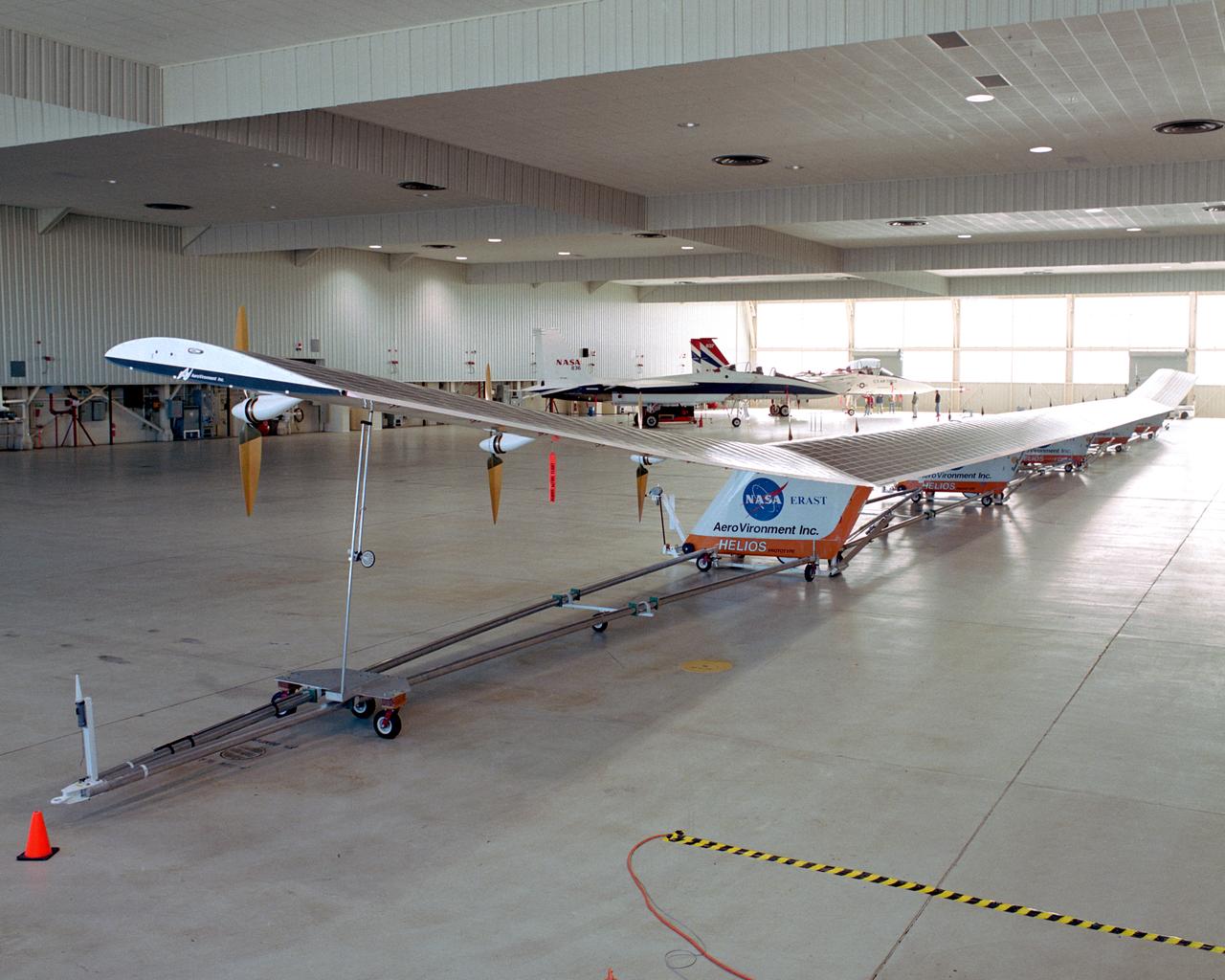
The solar-powered Helios Prototype flying wing frames two modified F-15 research aircraft in a hangar at NASA's Dryden Flight Research Center, Edwards, California. The elongated 247-foot span lightweight aircraft, resting on its ground maneuvering dolly, stretched almost the full length of the 300-foot long hangar while on display during a visit of NASA Administrator Sean O'Keefe and other NASA officials on Jan. 31, 2002. The unique solar-electric flying wing reached an altitude of 96,863 feet during an almost 17-hour flight near Hawaii on Aug. 13, 2001, a world record for sustained horizontal flight by a non-rocket powered aircraft. Developed by AeroVironment, Inc., under NASA's Environmental Research Aircraft and Sensor Technology (ERAST) project, the Helios Prototype is the forerunner of a planned fleet of slow-flying, long duration, high-altitude uninhabited aerial vehicles (UAV) which can serve as "atmospheric satellites," performing Earth science missions or functioning as telecommunications relay platforms in the stratosphere.
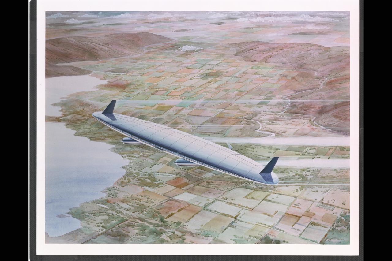
Artwork: N/A Flying Wing at Airport taxing to gate

Event: SEG 410 Main Wing A Lockheed Martin technician works on the installation of wiring on the trailing edge structure of the right side of the X-59’s wing. The aircraft, under construction at Lockheed Martin Skunk Works in Palmdale, California, will demonstrate the ability to fly supersonic while reducing the loud sonic boom to a quiet sonic thump.
Artist: Rick Guidice Flying Oblique Wing designed by R.T. Jones Artwork
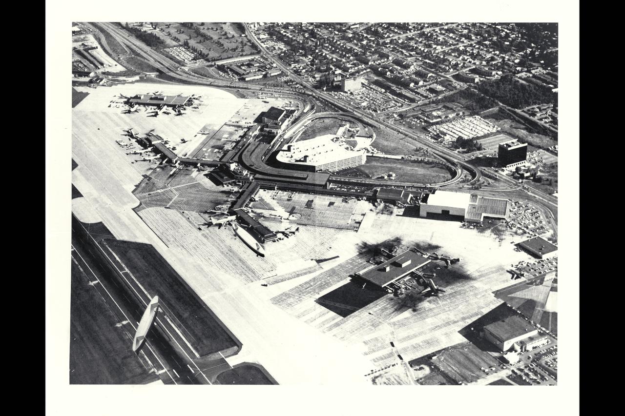
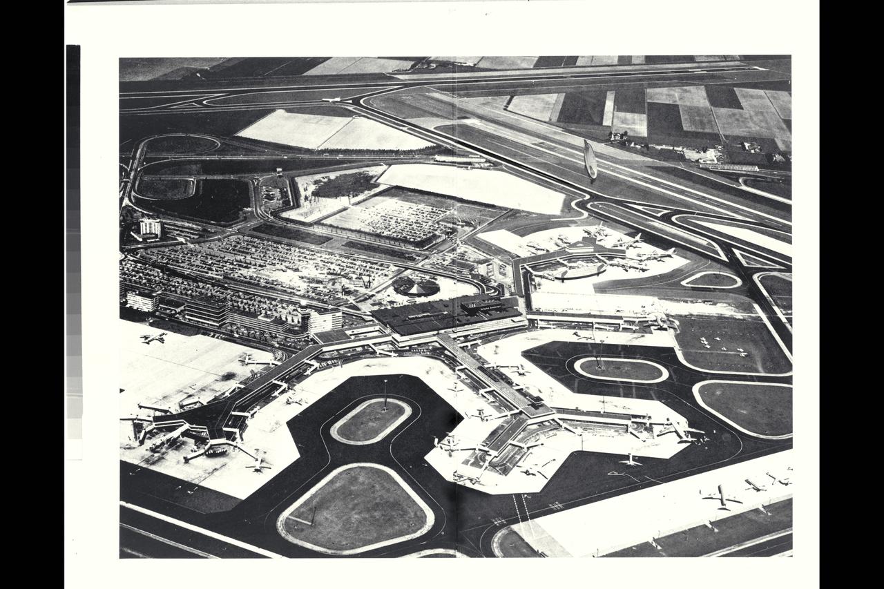
Artwork: N/A Flying Wing at Airport: approach on taxi way and at gate showing passenger loading concept
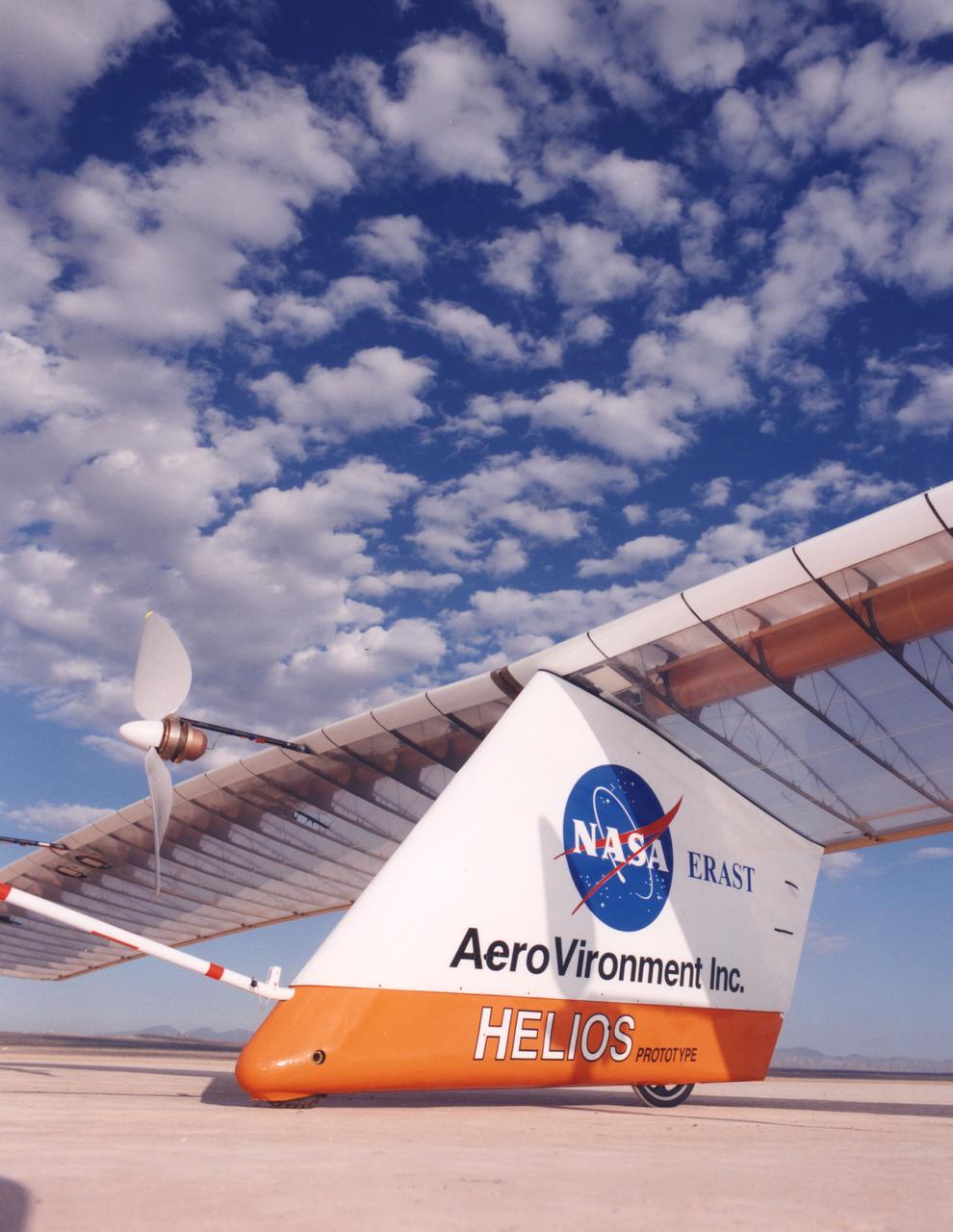
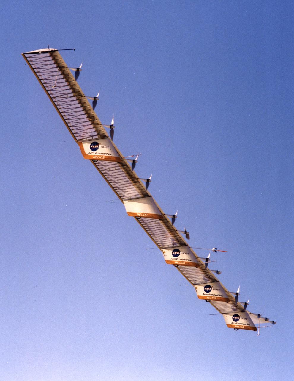
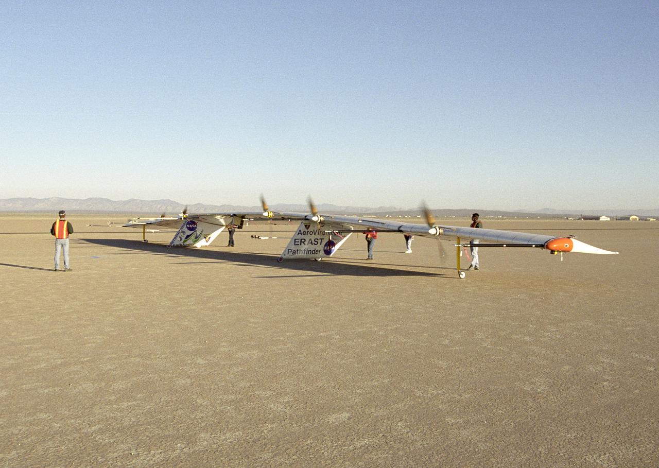
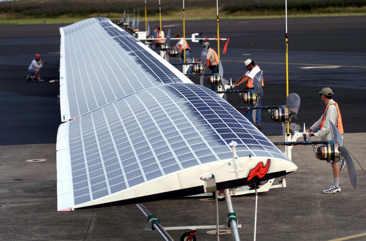
Closeup of the Helios Prototype, the latest and largest example of a slow-flying ultralight flying wing designed for high-altitude, long-duration Earth science or telecommunications relay missions.
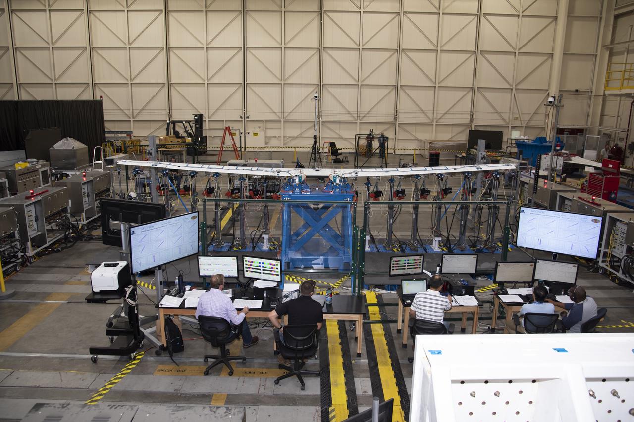
The X-57 distributed electric aircraft wing that will fly in the final configuration of the flight tests completed its testing at NASA's Armstrong Flight Research Center in California. The test above researched the wing's structure under stress of 120% of the design limit. Tests increased confidence in the wing's durability and calibrated installed strain gauges for inflight load monitoring of the wing. From left to right are Eric Miller, Tony Cash, Welsey Li, Shun-fat Lung and Ashante Jordan.
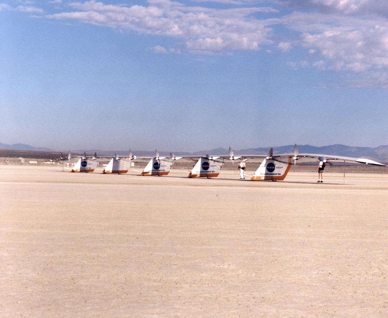
The Helios Prototype is an enlarged version of the Centurion flying wing, which flew a series of test flights at Dryden in late 1998. The craft has a wingspan of 247 feet, 41 feet greater than the Centurion, 2 1/2 times that of its solar-powered Pathfinder flying wing, and longer than either the Boeing 747 jetliner or Lockheed C-5 transport aircraft.
The Helios Prototype is an enlarged version of the Centurion flying wing, which flew a series of test flights at Dryden in late 1998. The craft has a wingspan of 247 feet, 41 feet greater than the Centurion, 2 1/2 times that of its solar-powered Pathfinder flying wing, and longer than either the Boeing 747 jetliner or Lockheed C-5 transport aircraft.
The Helios Prototype is an enlarged version of the Centurion flying wing, which flew a series of test flights at Dryden in late 1998. The craft has a wingspan of 247 feet, 41 feet greater than the Centurion, 2 1/2 times that of its solar-powered Pathfinder flying wing, and longer than either the Boeing 747 jetliner or Lockheed C-5 transport aircraft.
The Helios Prototype is an enlarged version of the Centurion flying wing, which flew a series of test flights at Dryden in late 1998. The craft has a wingspan of 247 feet, 41 feet greater than the Centurion, 2 1/2 times that of its solar-powered Pathfinder flying wing, and longer than either the Boeing 747 jetliner or Lockheed C-5 transport aircraft.
The Helios Prototype is an enlarged version of the Centurion flying wing, which flew a series of test flights at Dryden in late 1998. The craft has a wingspan of 247 feet, 41 feet greater than the Centurion, 2 1/2 times that of its solar-powered Pathfinder flying wing, and longer than either the Boeing 747 jetliner or Lockheed C-5 transport aircraft.
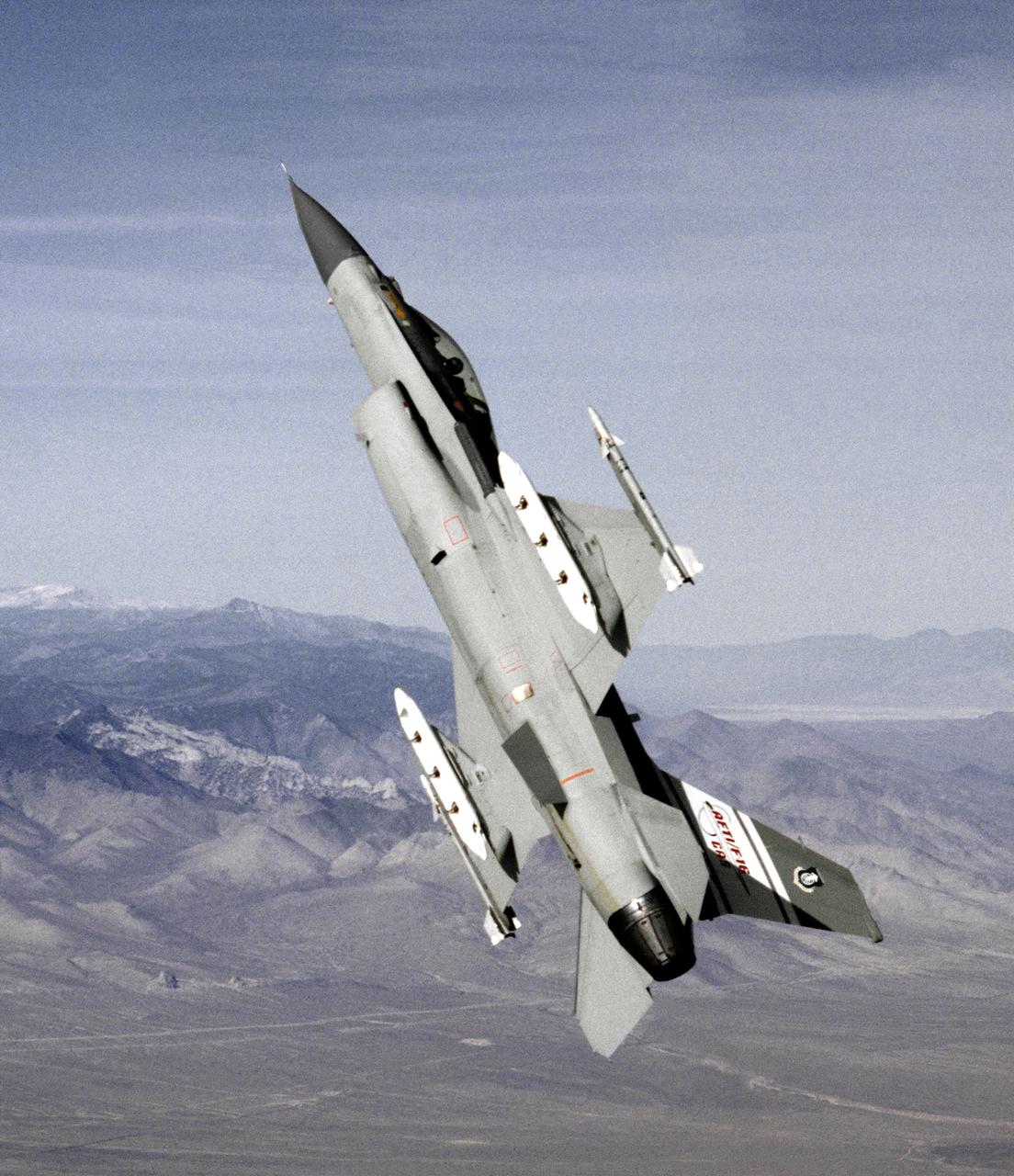
The AFTI F-16 flying at high angle of attack, shown in the final configuration and paint finish. Dummy Sidewinder air-to-air missles are attached to the wing tips. The white objects visible on the wing racks represent practice bomb dispensers, used in weapon tests.
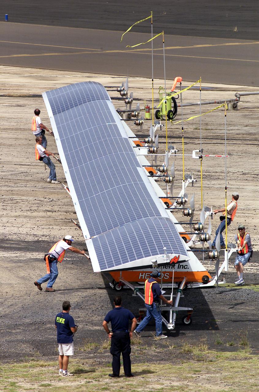
The 247-foot length of the Helios prototype wing is in evidence as the high-altitude, solar-powered flying wing rests on its ground dolly during pre-flight tests at the U.S. Navy's Pacific Missile Range Facility on Kaua'i, Hawaii.
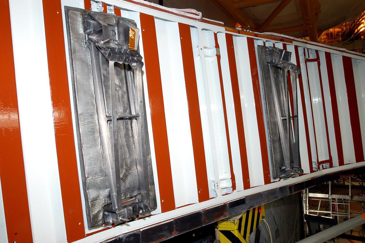
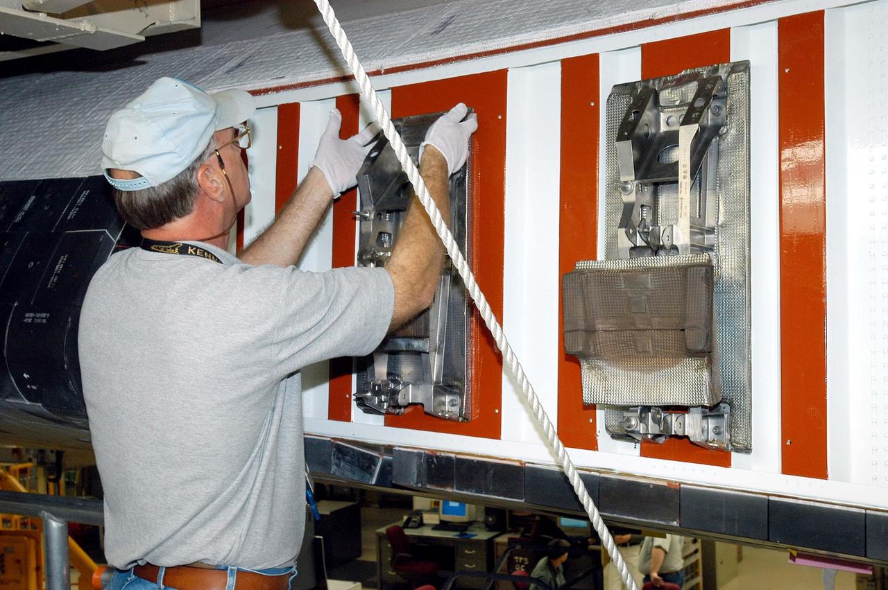
KENNEDY SPACE CENTER, FLA. - In the Orbiter Processing Facility, the left wing leading edge on Discovery is ready for installation of the first Reinforced Carbon-Carbon panel. The RCC panels are mechanically attached to the wing with spars, a series of floating joints to reduce loading on the panels caused by wing deflections. Discovery has been named as the orbiter to fly on the first Return to Flight mission, STS-114.
KENNEDY SPACE CENTER, FLA. - In the Orbiter Processing Facility, United Space Alliance technicians Dave Fuller (rear) and Jim Burgess (front) continue installing the first Reinforced Carbon-Carbon panel on the left wing leading edge of Discovery. The RCC panels are mechanically attached to the wing with spars, a series of floating joints to reduce loading on the panels caused by wing deflections. Discovery has been named as the orbiter to fly on the first Return to Flight mission, STS-114.
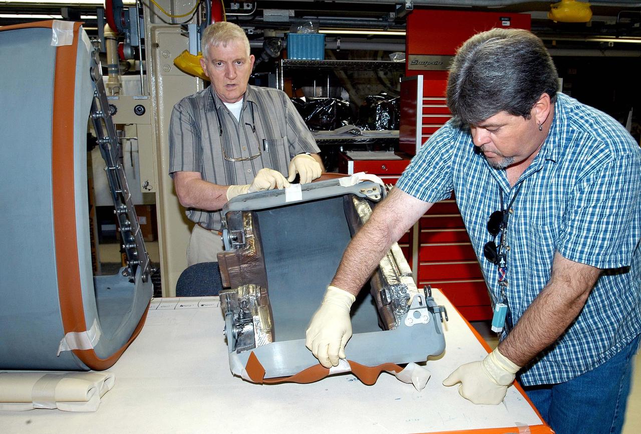
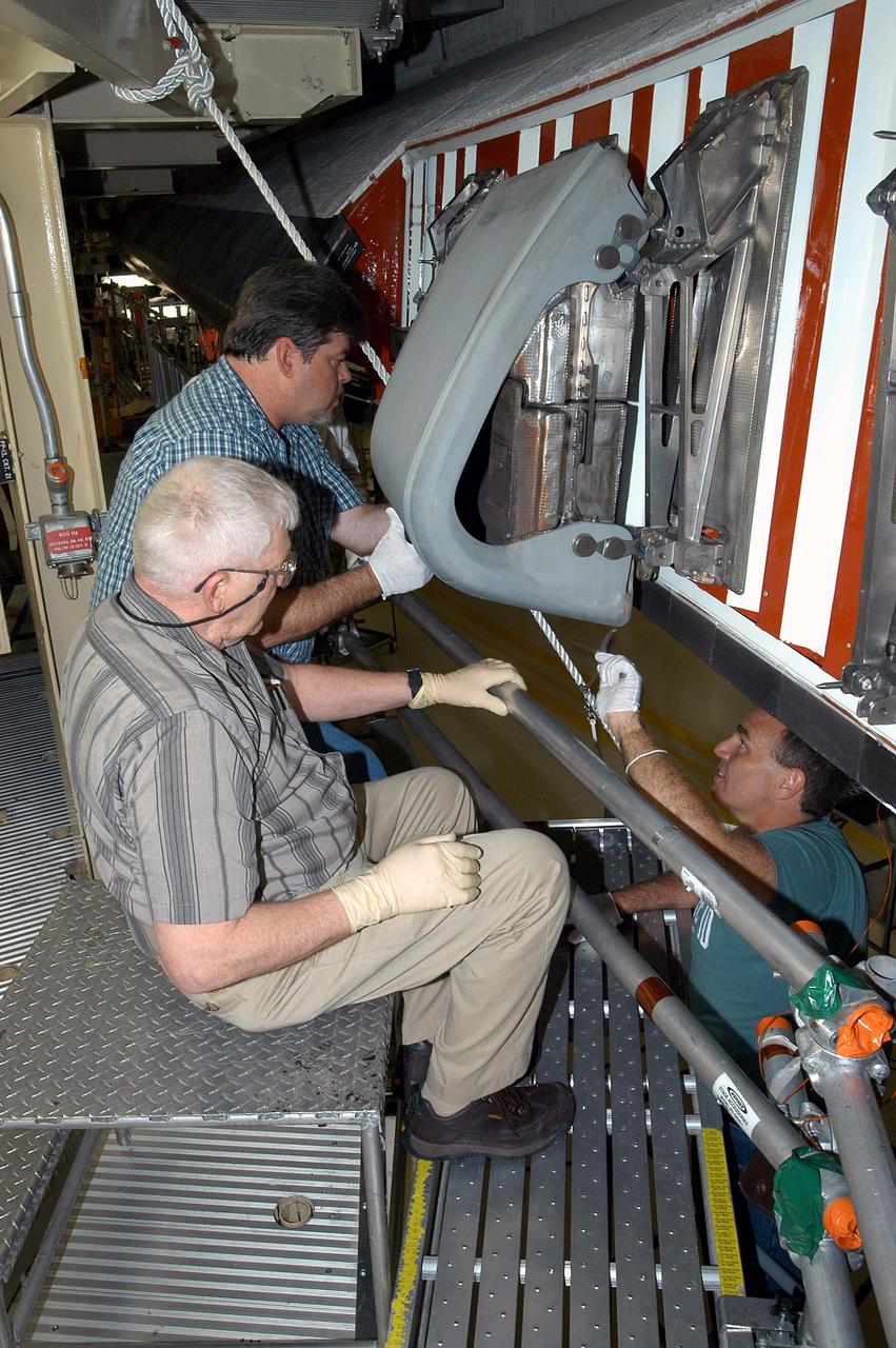
KENNEDY SPACE CENTER, FLA. - In the Orbiter Processing Facility, United Space Alliance technicians Jim Burgess (left) and Dave Fuller (right) prepare the first Reinforced Carbon-Carbon panel for installation on the left wing leading edge on Discovery. The RCC panels are mechanically attached to the wing with spars, a series of floating joints to reduce loading on the panels caused by wing deflections. Discovery has been named as the orbiter to fly on the first Return to Flight mission, STS-114.
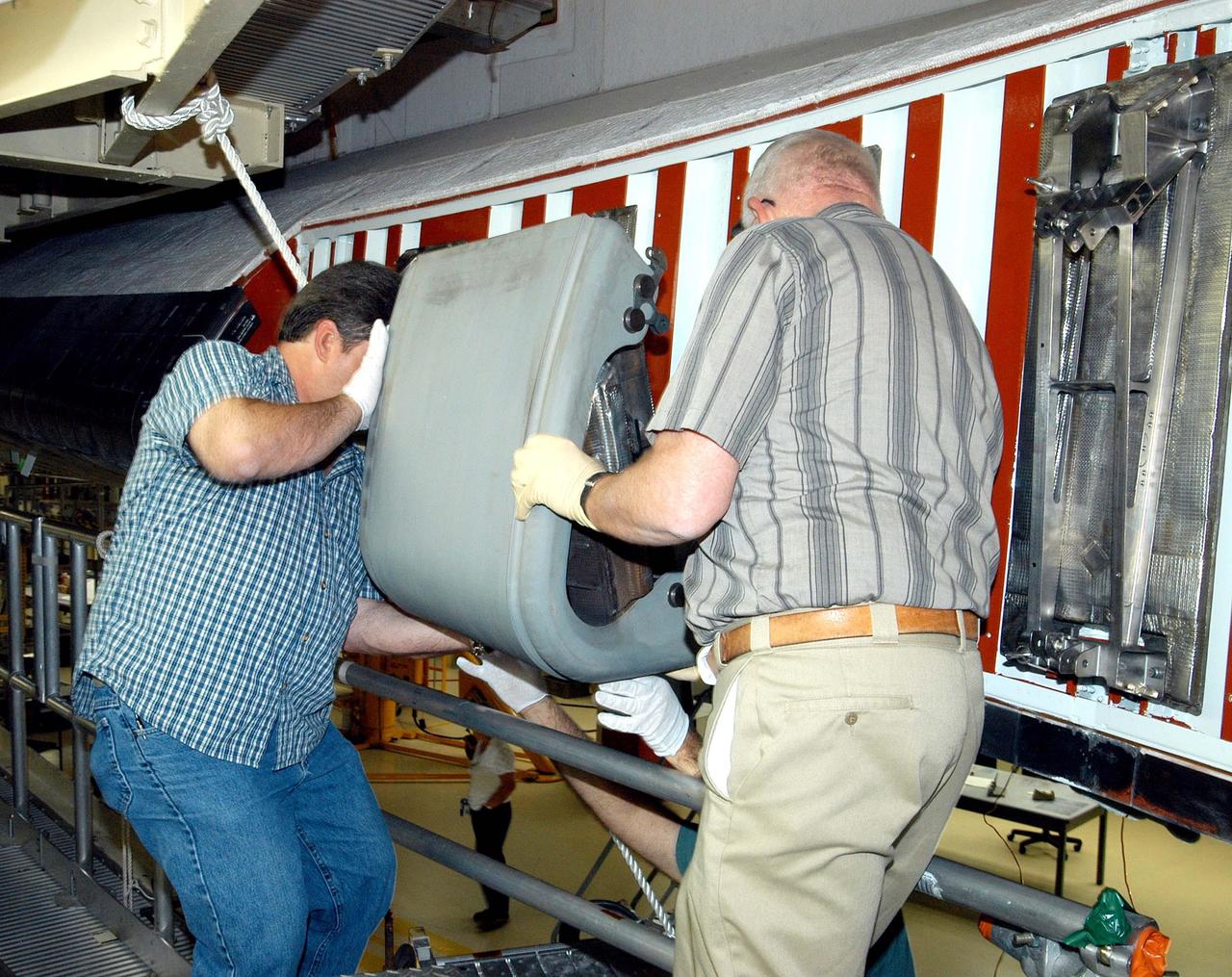
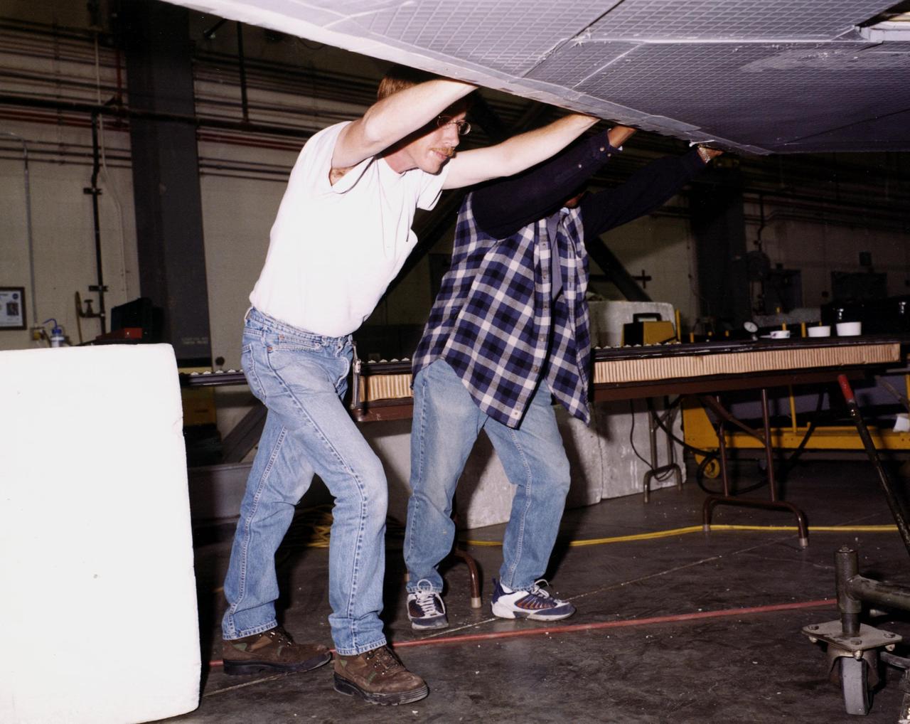
KENNEDY SPACE CENTER, FLA. - In the Orbiter Processing Facility, United Space Alliance technicians Dave Fuller (left) and Jim Burgess (right) lift the first Reinforced Carbon-Carbon panel toward the left wing leading edge of Discovery for installation. The RCC panels are mechanically attached to the wing with spars, a series of floating joints to reduce loading on the panels caused by wing deflections. Discovery has been named as the orbiter to fly on the first Return to Flight mission, STS-114.
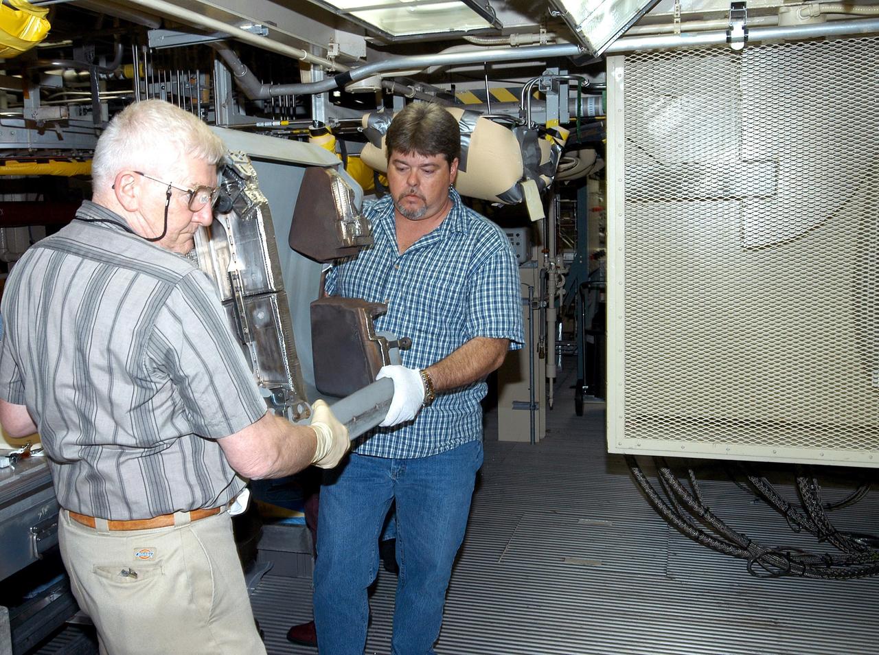
KENNEDY SPACE CENTER, FLA. - In the Orbiter Processing Facility, United Space Alliance technicians Jim Burgess (left) and Dave Fuller (right) carry the first Reinforced Carbon-Carbon panel toward the left wing leading edge of Discovery for installation. The RCC panels are mechanically attached to the wing with spars, a series of floating joints to reduce loading on the panels caused by wing deflections. Discovery has been named as the orbiter to fly on the first Return to Flight mission, STS-114.
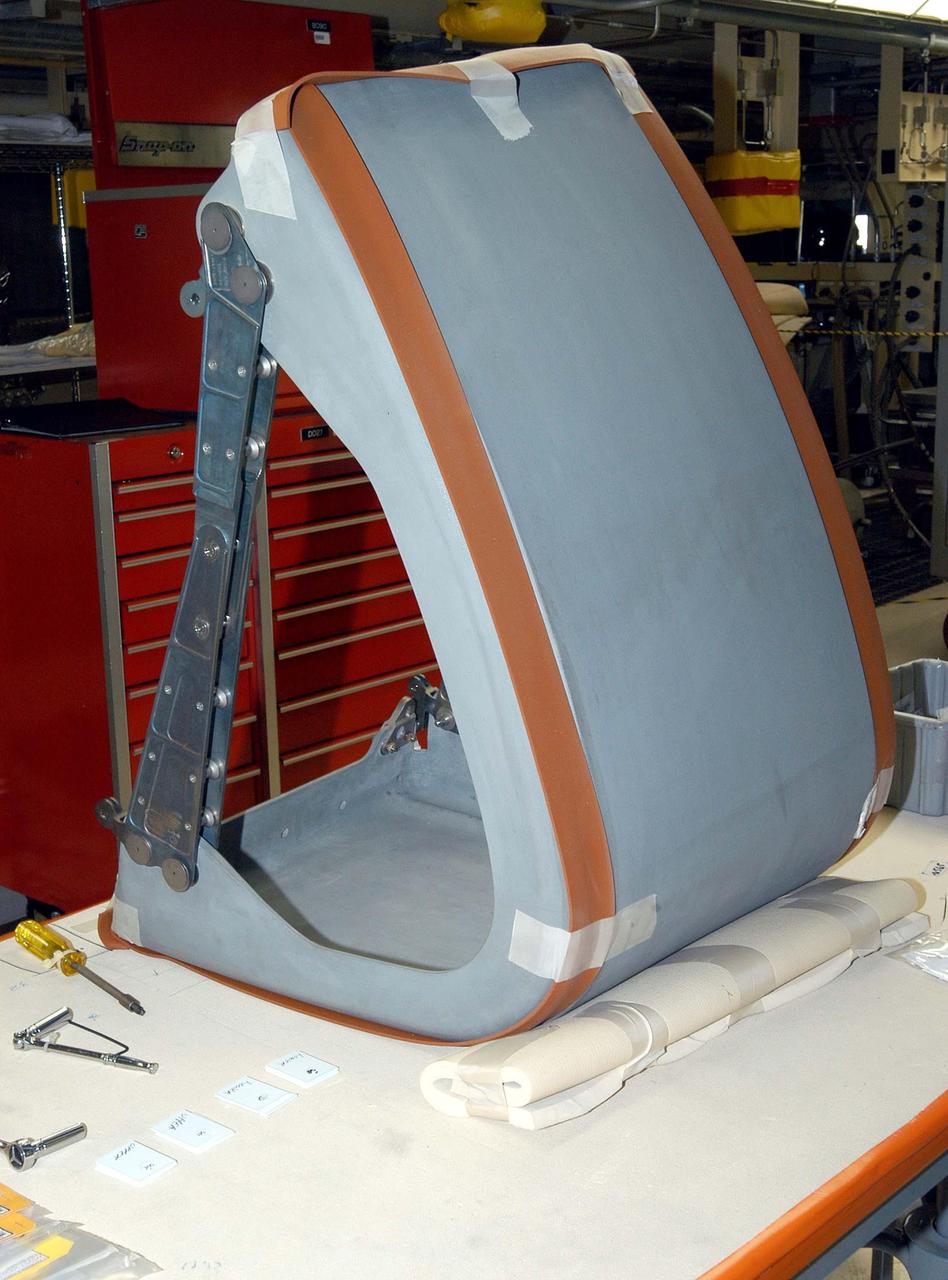
KENNEDY SPACE CENTER, FLA. - In the Orbiter Processing Facility, the first Reinforced Carbon-Carbon panel is ready for installation on the left wing leading edge on Discovery. The RCC panels are mechanically attached to the wing with spars, a series of floating joints to reduce loading on the panels caused by wing deflections. Discovery has been named as the orbiter to fly on the first Return to Flight mission, STS-114.

KENNEDY SPACE CENTER, FLA. - In the Orbiter Processing Facility, United Space Alliance technician Jim Burgess installs the first Reinforced Carbon-Carbon panel on the left wing leading edge of Discovery. The RCC panels are mechanically attached to the wing with spars, a series of floating joints to reduce loading on the panels caused by wing deflections. Discovery has been named as the orbiter to fly on the first Return to Flight mission, STS-114.
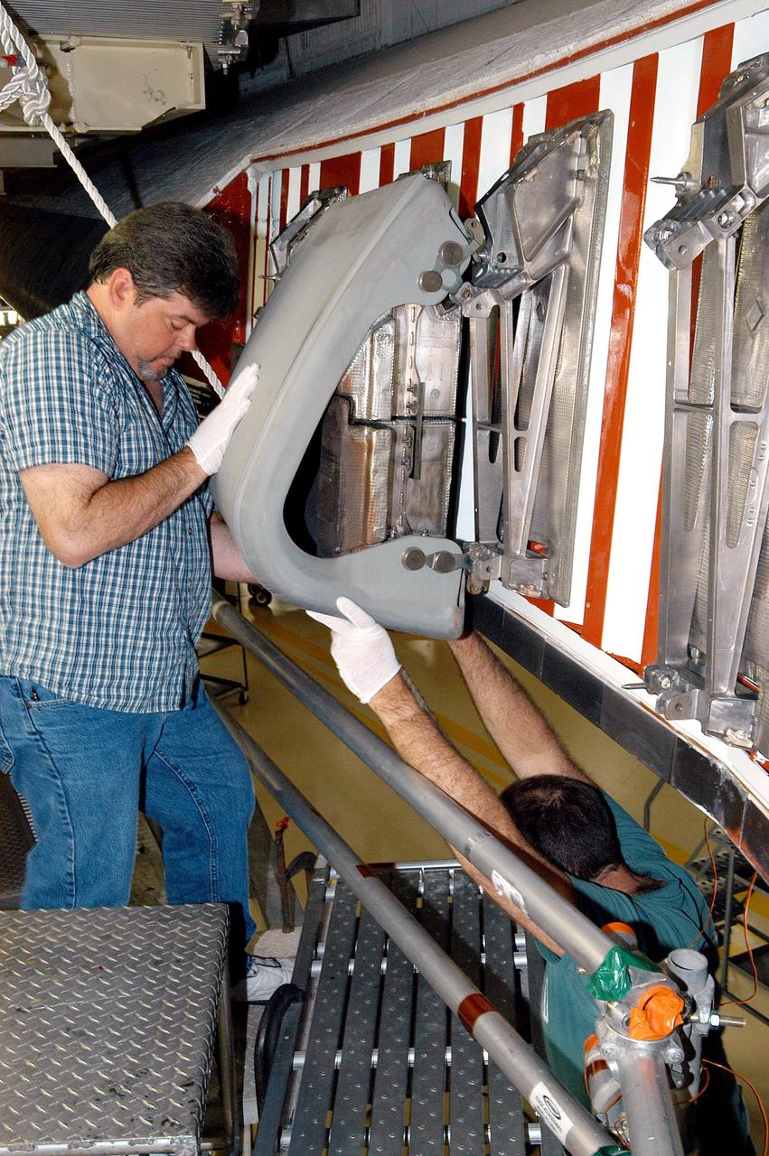
KENNEDY SPACE CENTER, FLA. - In the Orbiter Processing Facility, United Space Alliance technician Dave Fuller installs the first Reinforced Carbon-Carbon panel on the left wing leading edge of Discovery. The RCC panels are mechanically attached to the wing with spars, a series of floating joints to reduce loading on the panels caused by wing deflections. Discovery has been named as the orbiter to fly on the first Return to Flight mission, STS-114.
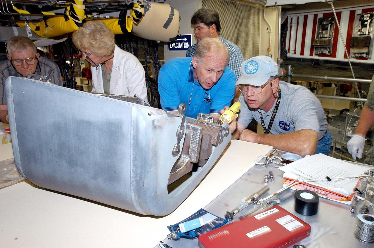
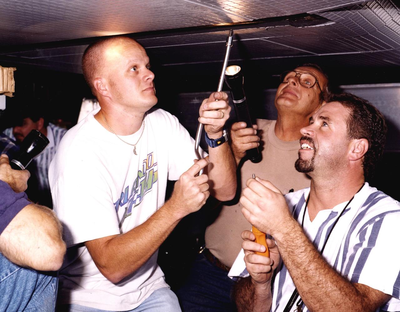
KENNEDY SPACE CENTER, FLA. - In the Orbiter Processing Facility, Danny Wyatt, NASA Quality Assurance specialist, and John Legere (right), NASA Quality Assurance specialist, examine the first Reinforced Carbon-Carbon panel to be installed on the left wing leading edge on Discovery. The RCC panels are mechanically attached to the wing with spars, a series of floating joints to reduce loading on the panels caused by wing deflections. Discovery has been named as the orbiter to fly on the first Return to Flight mission, STS-114.
KENNEDY SPACE CENTER, FLA. - In the Orbiter Processing Facility, John Legere, NASA Quality Assurance specialist, examines the attachment point for the first Reinforced Carbon-Carbon panel to be installed on the left wing leading edge of Discovery. The RCC panels are mechanically attached to the wing with spars, a series of floating joints to reduce loading on the panels caused by wing deflections. Discovery has been named as the orbiter to fly on the first Return to Flight mission, STS-114.
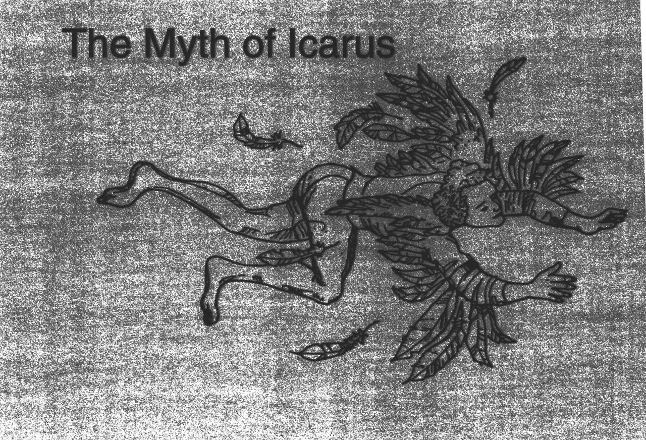
Ever since humans first saw birds soar through the sky, they have wanted to fly. The ancient Greeks and Romans pictured many of their gods with winged feet, and imagined mythological winged animals. According to the legend of Daedalus and Icarus, the father and son escaped prison by attaching wings made of wax and feathers to their bodies. Unfortunately, Icarus flew too near the sun, and the heat caused the wax and feathers to melt. The feathers fell off, and Icarus plummeted to the sea. Daedalus landed safely in Sicily.
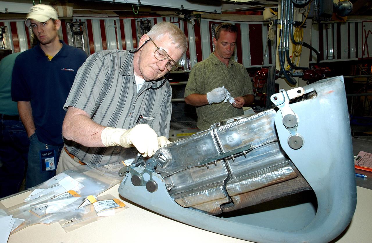
KENNEDY SPACE CENTER, FLA. - In the Orbiter Processing Facility, United Space Alliance technician Jim Burgess (right) works on the first Reinforced Carbon-Carbon panel to be installed on the left wing leading edge on Discovery. At left is USA technician Dave Fuller. The RCC panels are mechanically attached to the wing with spars, a series of floating joints to reduce loading on the panels caused by wing deflections. Discovery has been named as the orbiter to fly on the first Return to Flight mission, STS-114.
KENNEDY SPACE CENTER, FLA. - In the Orbiter Processing Facility, United Space Alliance technicians Dave Fuller (left) and Jim Burgess (right) lift into place the first Reinforced Carbon-Carbon panel toward the left wing leading edge of Discovery for installation. The RCC panels are mechanically attached to the wing with spars, a series of floating joints to reduce loading on the panels caused by wing deflections. Discovery has been named as the orbiter to fly on the first Return to Flight mission, STS-114.
KENNEDY SPACE CENTER, FLA. - In the Orbiter Processing Facility, Danny Wyatt, NASA Quality Assurance specialist, examines the attachment point for the first Reinforced Carbon-Carbon panel to be installed on the left wing leading edge of Discovery. The RCC panels are mechanically attached to the wing with spars, a series of floating joints to reduce loading on the panels caused by wing deflections. Discovery has been named as the orbiter to fly on the first Return to Flight mission, STS-114.
KENNEDY SPACE CENTER, FLA. - In the Orbiter Processing Facility, United Space Alliance technician Jim Burgess (right) works on the first Reinforced Carbon-Carbon panel to be installed on the left wing leading edge on Discovery. At left is USA technician Dave Fuller. The RCC panels are mechanically attached to the wing with spars, a series of floating joints to reduce loading on the panels caused by wing deflections. Discovery has been named as the orbiter to fly on the first Return to Flight mission, STS-114.
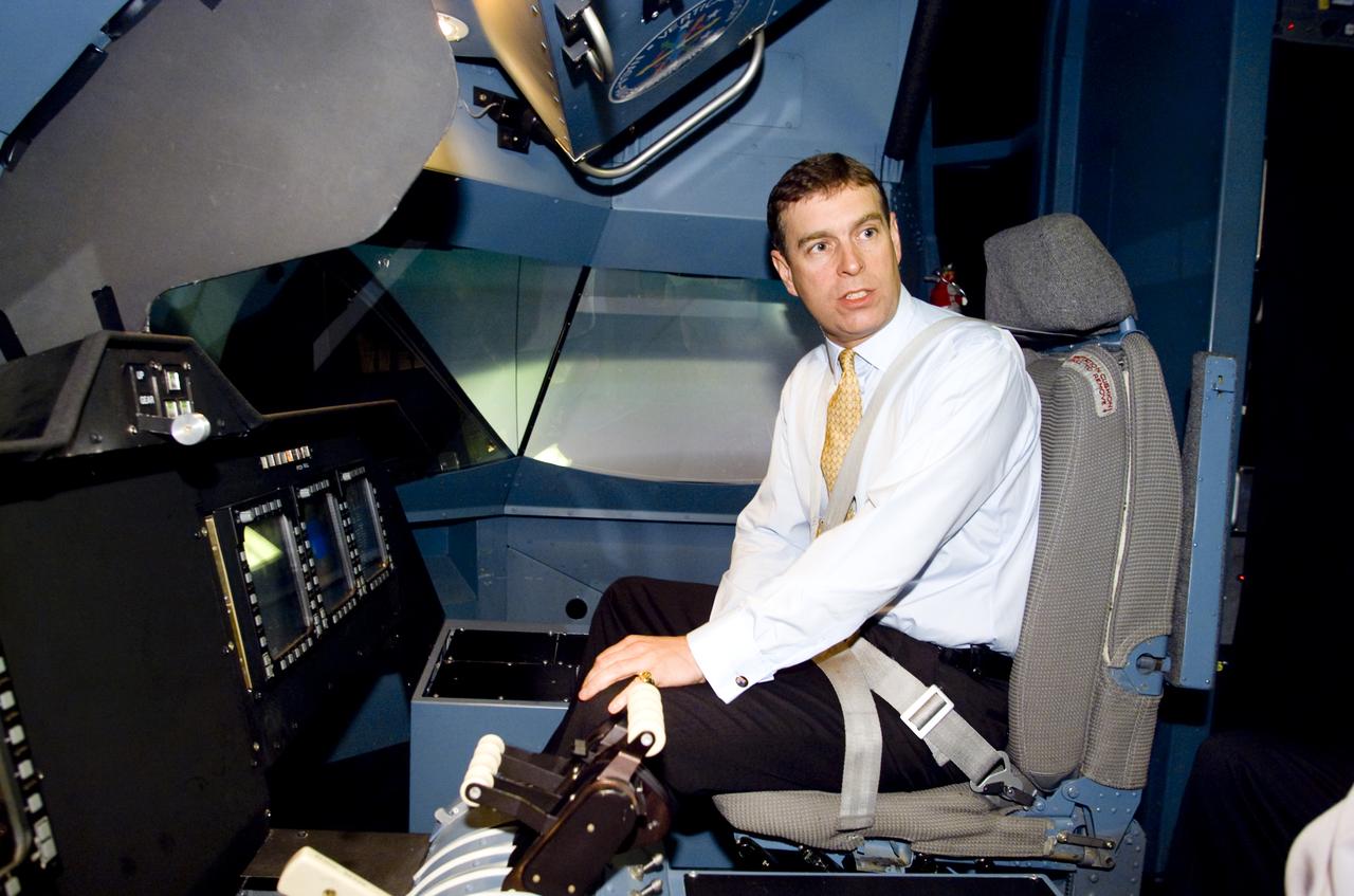
British Royalty visits Ames; Prince Andrew, Duke of York on tour. Seen here in the Vertical Motion Simulator in N-243 flying a tilt-wing simulation. (VMS)

Oblique Wing model mounted in 11ft W. T. with R. T. Jones, Designer/Engineer. The asymmetrical design allows the plane to fly much faster, yet consume the same fuel and generate less noise.
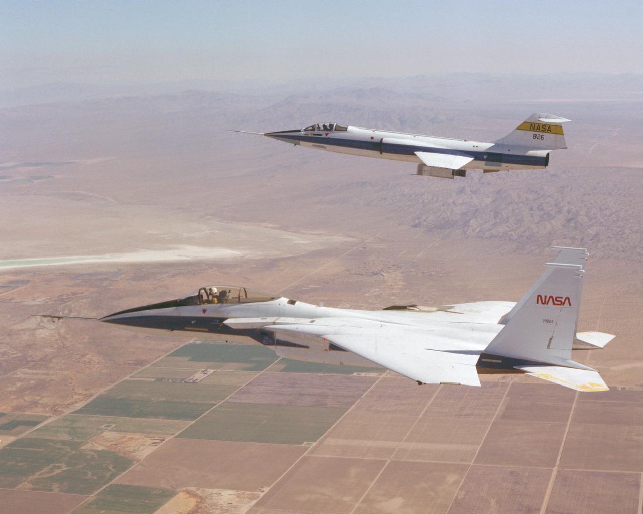
F-15 #281 and F-104 #826 fly in formation during Space Shuttle tile testing. Note the tiles mounted on the right wing of the F-15 and the centerline test fixture of the F-104.
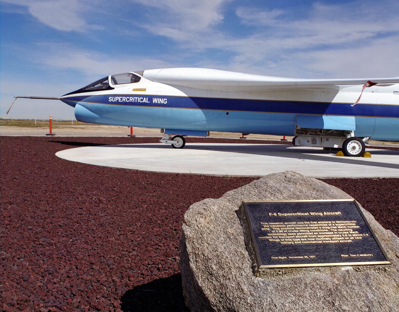
A Vought F-8A Crusader was selected by NASA as the testbed aircraft (designated TF-8A) to install an experimental Supercritical Wing (SCW) in place of the conventional wing. The unique design of the Supercritical Wing reduces the effect of shock waves on the upper surface near Mach 1, which in turn reduces drag. In the photograph the TF-8A Crusader with the Supercritical Wing is shown on static display in front of the NASA Dryden Flight Research Center, Edwards, California. The F-8 SCW aircraft, along with the F-8 Digital Fly-By-Wire aircraft were placed on display on May 27, 1992, at a conference marking the 20th anniversary of the start of the two programs.
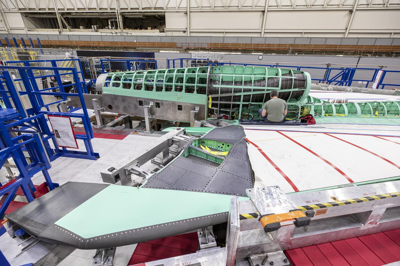
Here is a wide shot of the wing, engine and engine inlet area of NASA’s X-59 Quiet SuperSonic Technology or QueSST aircraft. The aircraft, under construction at Lockheed Martin Skunk Works in Palmdale, California, will fly to demonstrate the ability to fly supersonic while reducing the loud sonic boom to a quiet sonic thump. Lockheed Martin Photography By Garry Tice 1011 Lockheed Way, Palmdale, Ca. 93599 Event: SEG 400 Main Wing Assembly, SEG 430 Spine, SEG 500 Empennage Date: 4/28/2021
AeroVironment ground crew check out the operation of the Pathfinder-Plus solar aircraft's electric motors during combined systems tests on Rogers Dry Lake.

KENNEDY SPACE CENTER, FLA. - In the Orbiter Processing Facility, several workers check out the first Reinforced Carbon-Carbon panel to be installed on the left wing leading edge on Discovery. Second from right is Danny Wyatt, NASA Quality Assurance specialist; on the left is Dave Fuller, technician; behind Wyatt is John Legere, NASA Quality Assurance specialist. The RCC panels are mechanically attached to the wing with spars, a series of floating joints to reduce loading on the panels caused by wing deflections. The T-seals between each wing leading edge panel allow for lateral motion and thermal expansion differences between the RCC and the orbiter wing. Discovery has been named as the orbiter to fly on the first Return to Flight mission, STS-114.
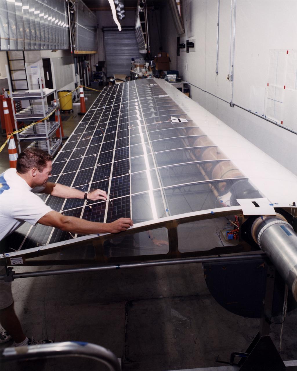
Technician Marshall MacCready carefully lays a panel of solar cells into place on a wing section of the Helios Prototype flying wing at AeroVironment's Design Development Center in Simi Valley, California. The bi-facial cells, manufactured by SunPower, Inc., of Sunnyvale, California, are among 64,000 solar cells which have been installed on the solar-powered aircraft to provide electricity to its 14 motors and operating systems.
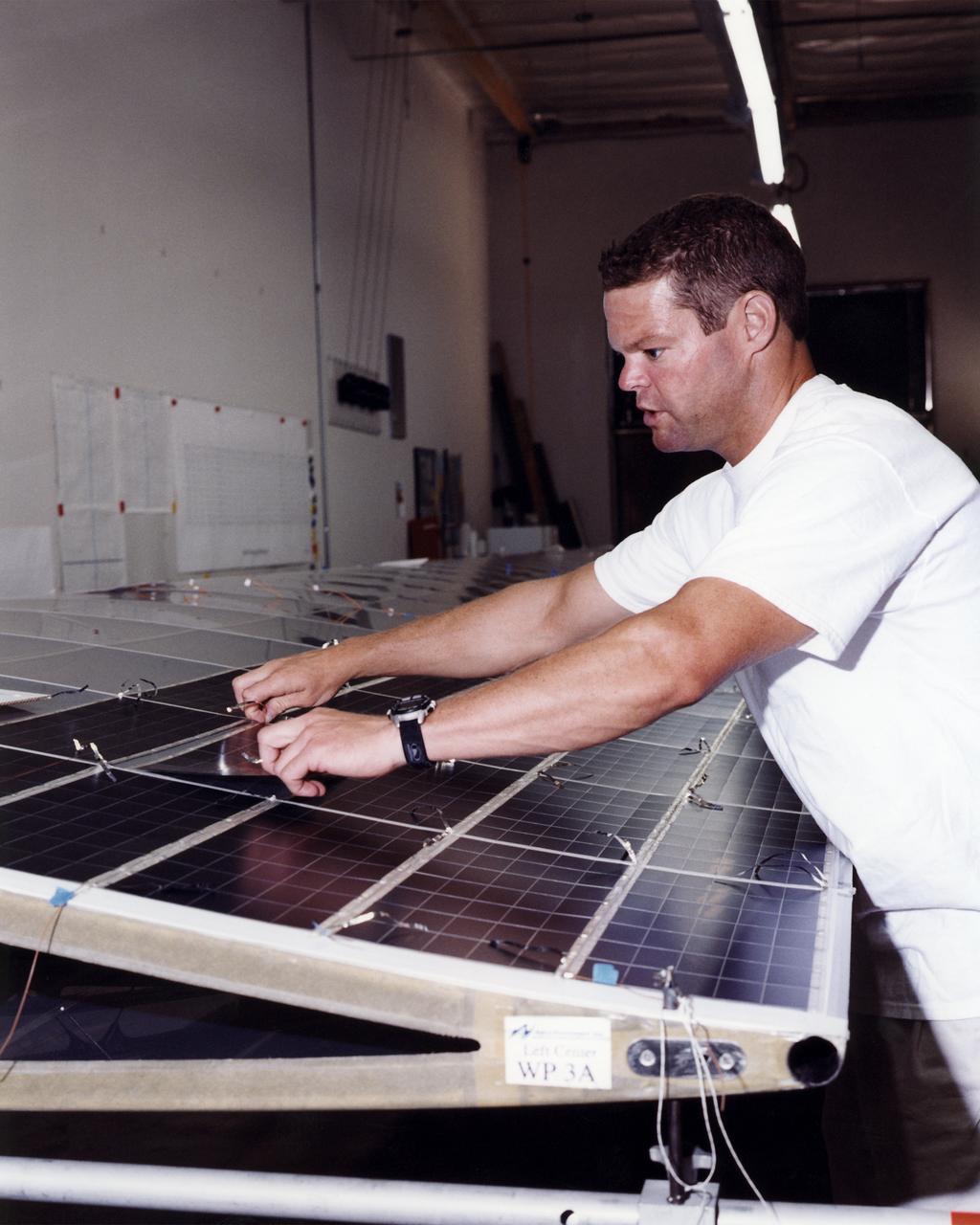
Technician Marshall MacCready carefully lays a panel of solar cells into place on a wing section of the Helios Prototype flying wing at AeroVironment's Design Development Center in Simi Valley, California. More than 1,800 panels containing some 64,000 bi-facial cells, fabricated by SunPower, Inc., of Sunnyvale, California, have been installed on the solar-powered aircraft to provide electricity to its 14 motors and operating systems.
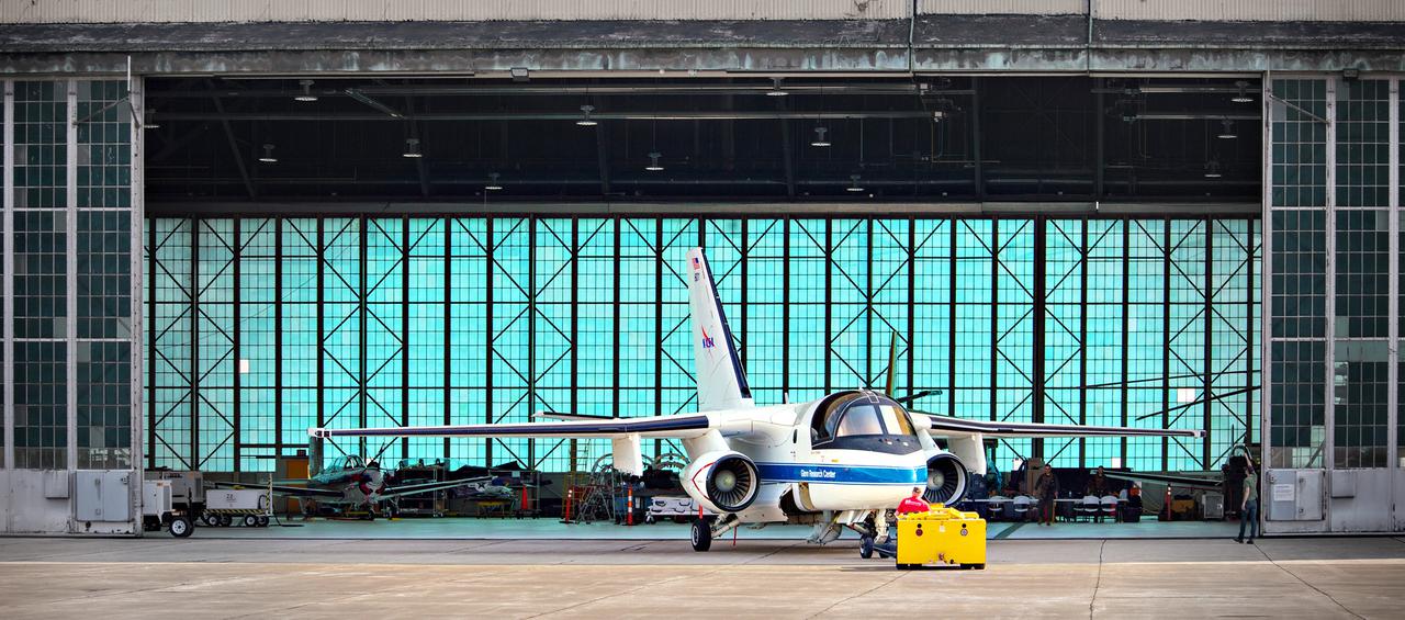
The Lockheed Viking S-3B aircraft is being pulled out of the hangar at Glenn Research Center in preparation for its departure and retirement from service. This former NAVY aircraft was the last such aircraft still flying. It has gone to a museum on the west coast. After leaving service with the NAVY, it came to GRC to be used in aircraft icing experiments. The swept wings made it suitable for such research as opposed to the straight wings on GRG’s other icing research aircraft, the De Havilland Twin Otter.
Ground crewmen maneuver AeroVironment's solar-powered Helios Prototype flying wing on its ground support dolly during functional checkouts prior to its first flights under solar power from the U.S. Navy's Pacific Missile Range Facility on Kaua'i, Hawaii.
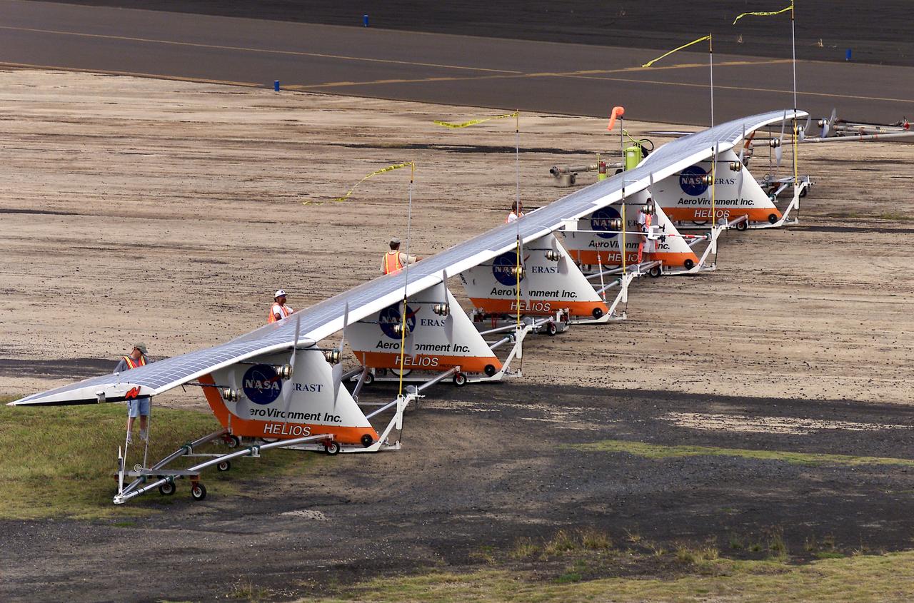
Ground crewmen maneuver AeroVironment's solar-powered Helios Prototype flying wing on its ground support dolly during functional checkouts prior to its first flights under solar power from the U.S. Navy's Pacific Missile Range Facility on Kaua'i, Hawaii.
Ground crewmen maneuver AeroVironment's solar-powered Helios Prototype flying wing on its ground support dolly during functional checkouts prior to its first flights under solar power from the U.S. Navy's Pacific Missile Range Facility on Kaua'i, Hawaii.
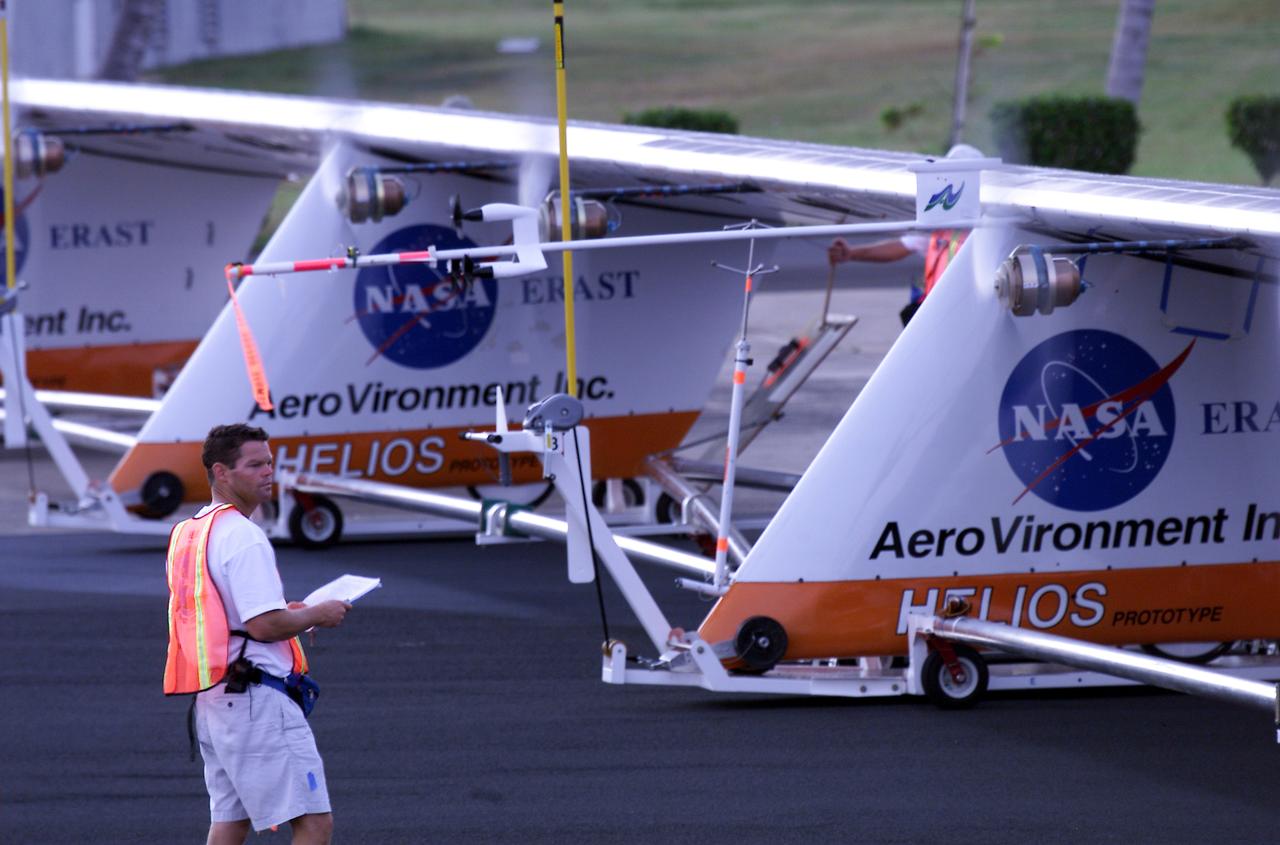
Helios Prototype crew chief Marshall MacCready of AeroVironment, Inc., carefully monitors motor runs during ground checkout of the solar-powered flying wing prior to its first flight from the U.S. Navy's Pacific Missile Range Facility on Kaua'i, Hawaii.
Ground crewmen maneuver AeroVironment's solar-powered Helios Prototype flying wing on its ground support dolly during functional checkouts prior to its first flights under solar power from the U.S. Navy's Pacific Missile Range Facility on Kaua'i, Hawaii.
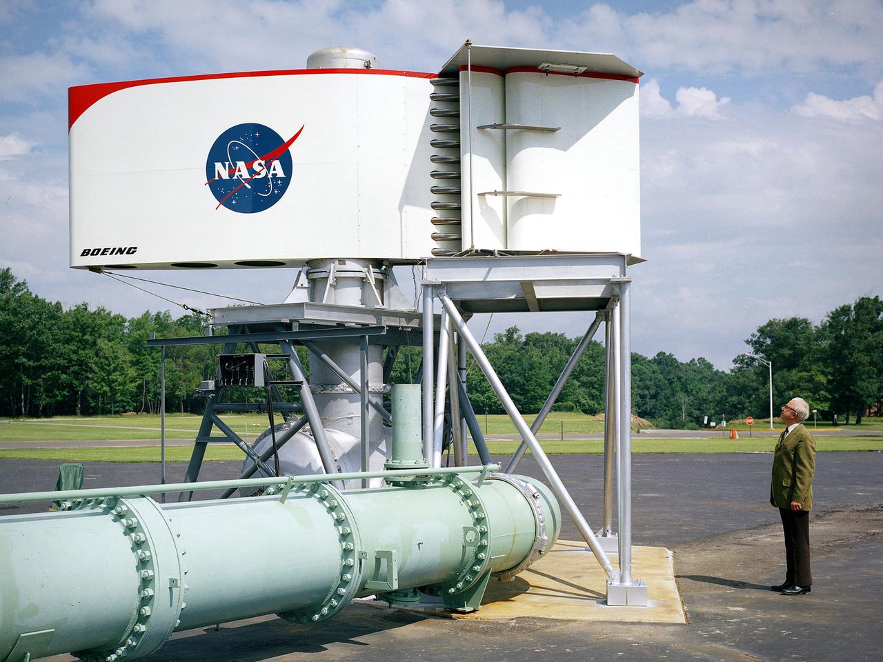
The augmentor wing concept was introduced during the early 1960s to enhance the performance of vertical and short takeoff (VSTOL) aircraft. The leading edge of the wing has full-span vertical flaps, and the trailing edge has double-slotted flaps. This provides aircraft with more control in takeoff and landing conditions. The augmentor wing also produced lower noise levels than other VSTOL designs. In the early 1970s Boeing Corporation built a Buffalo C-8A augmentor wing research aircraft for Ames Research Center. Researches at Lewis Research Center concentrated their efforts on reducing the noise levels of the wing. They initially used small-scale models to develop optimal nozzle screening methods. They then examined the nozzle designs on a large-scale model, seen here on an external test stand. This test stand included an airflow system, nozzle, the augmentor wing, and a muffler system below to reduce the atmospheric noise levels. The augmentor was lined with noise-reducing acoustic panels. The Lewis researchers were able to adjust the airflow to simulate conditions at takeoff and landing. Once the conditions were stabilized they took noise measurements from microphones placed in all directions from the wing, including an aircraft flying over. They found that the results coincided with the earlier small-scale studies for landing situations but not takeoffs. The acoustic panels were found to be successful.
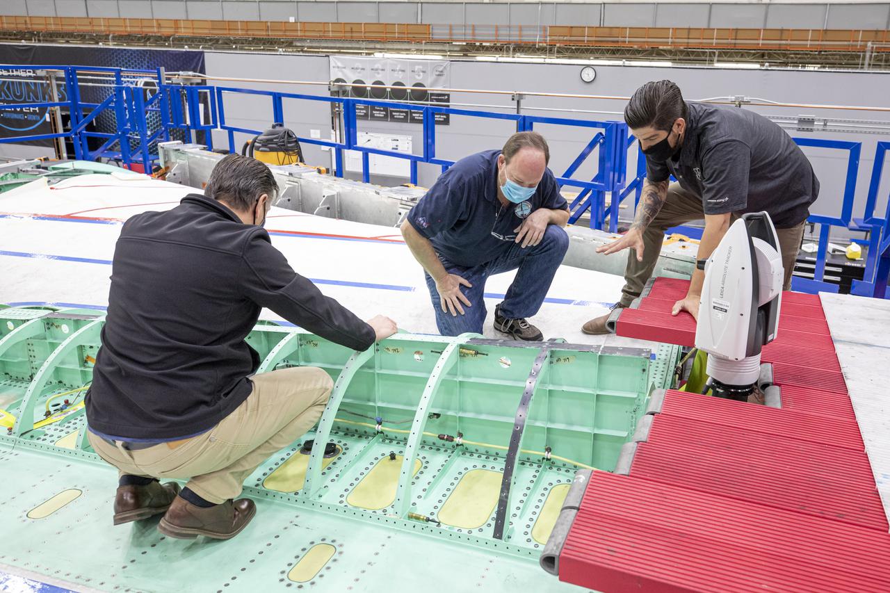
Technicians work with a laser measuring system on the X-59 spine. The X-59 Quiet SuperSonic Technology, or QueSST, aircraft is under construction at Lockheed Martin Skunk Works in Palmdale, California, and will fly to demonstrate the ability to fly supersonic while reducing the loud sonic boom to a quiet sonic thump. Lockheed Martin Photography By Garry Tice 1011 Lockheed Way, Palmdale, Ca. 93599 Event: SEG 400 Main Wing Assembly, SEG 430 Spine, SEG 500 Empennage Date: 4/28/2021
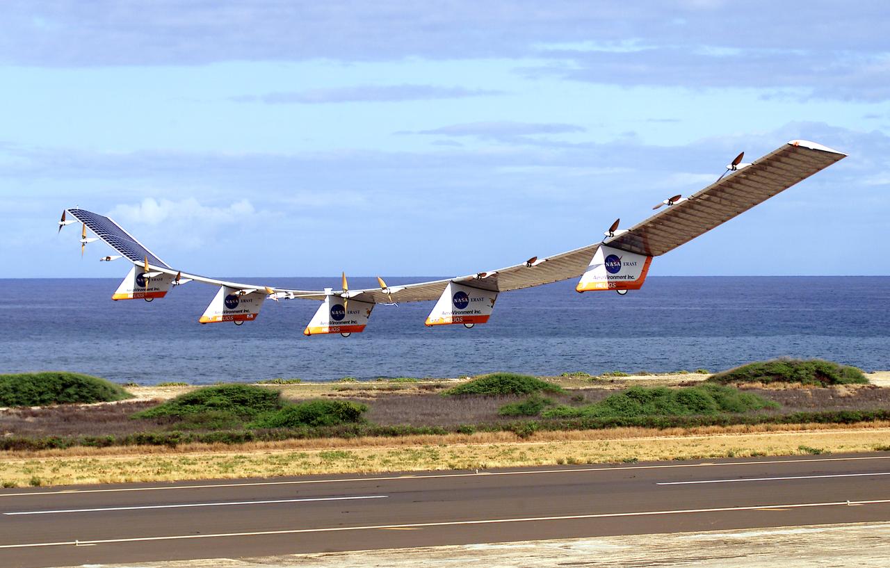
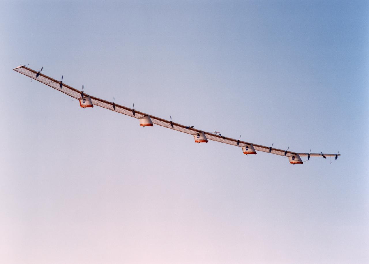
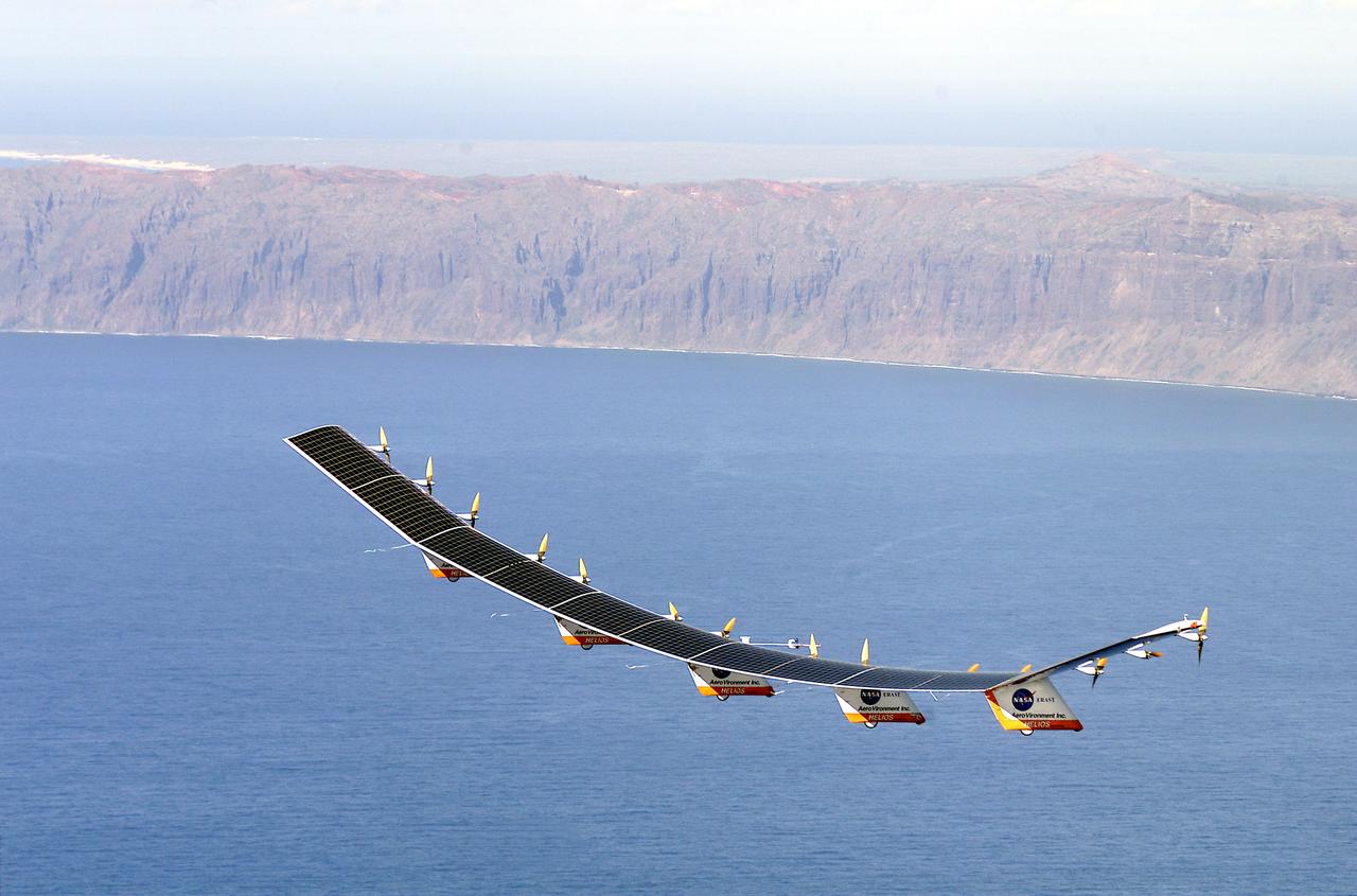
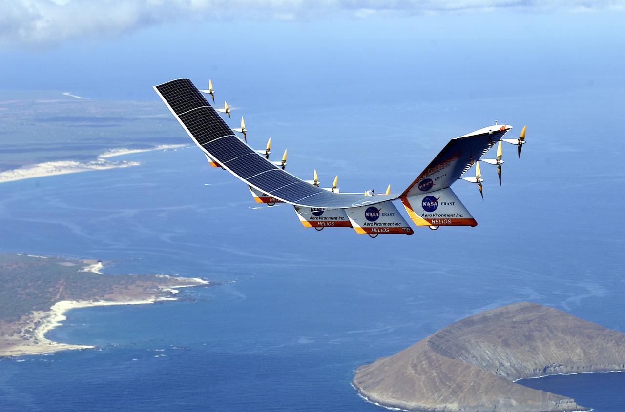
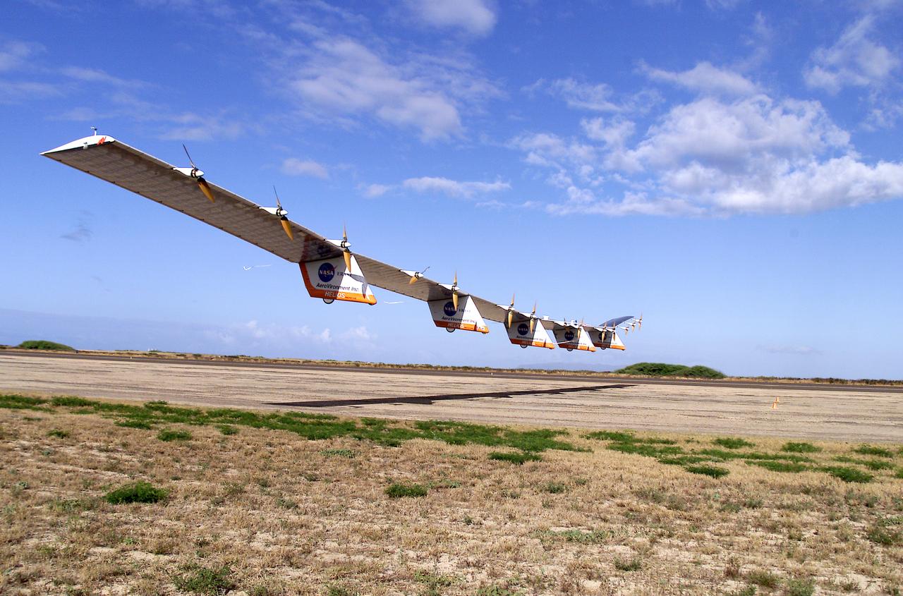
NASA's Helios Prototype aircraft taking off from the Pacific Missile Range Facility, Kauai, Hawaii, for the record flight. As a follow-on to the Centurion (and earlier Pathfinder and Pathfinder-Plus) aircraft, the solar-powered Helios Prototype is the latest and largest example of a slow-flying ultralight flying wing designed for long-duration, high-altitude Earth science or telecommunications relay missions in the stratosphere. Developed by AeroVironment, Inc., of Monrovia, California, under NASA's Environmental Research Aircraft and Sensor Technology (ERAST) project, the unique craft is intended to demonstrate two key missions: the ability to reach and sustain horizontal flight at 100,000 feet altitude on a single-day flight in 2001, and to maintain flight above 50,000 feet altitude for at least four days in 2003, with the aid of a regenerative fuel cell-based energy storage system now in development. Both of these missions will be powered by electricity derived from non-polluting solar energy. The Helios Prototype is an enlarged version of the Centurion flying wing, which flew a series of test flights at NASA's Dryden Flight Research Center in late 1998. The craft has a wingspan of 247 feet, 41 feet greater than the Centurion, 2 1/2 times that of its solar-powered Pathfinder flying wing, and longer than the wingspans of either the Boeing 747 jetliner or Lockheed C-5 transport aircraft. The remotely piloted, electrically powered Helios Prototype went aloft on its maiden low-altitude checkout flight Sept. 8, 1999, over Rogers Dry Lake adjacent to NASA's Dryden Flight Research Center in the Southern California desert. The initial flight series was flown on battery power as a risk-reduction measure. In all, six flights were flown in the Helios Protoype's initial development series. In upgrading the Centurion to the Helios Prototype configuration, AeroVironment added a sixth wing section and a fifth landing gear pod, among other improvements. The additional wingsp
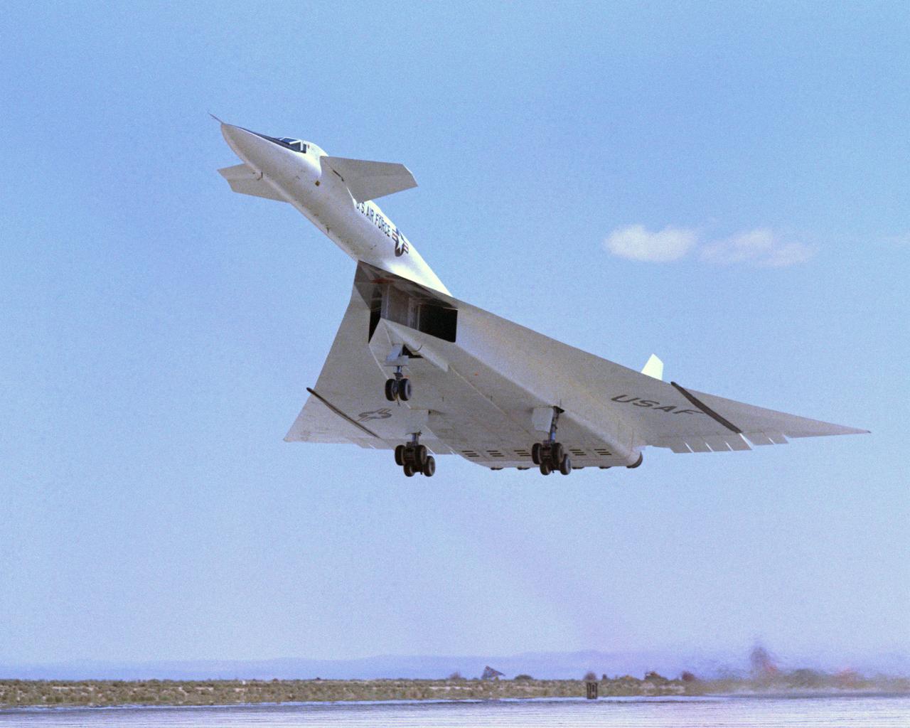
Viewed from the front the #1 XB-70A (62-0001) is shown climbing out during take-off. Most flights were scheduled during the morning hours to take advantage of the cooler ambient air temperatures for improved propulsion efficiencies. The wing tips are extended straight out to provide a maximum lifting wing surface. The XB-70A, capable of flying three times the speed of sound, was the world's largest experimental aircraft in the 1960s. Two XB-70A aircraft were built. Ship #1 was flown by NASA in a high speed flight research program.
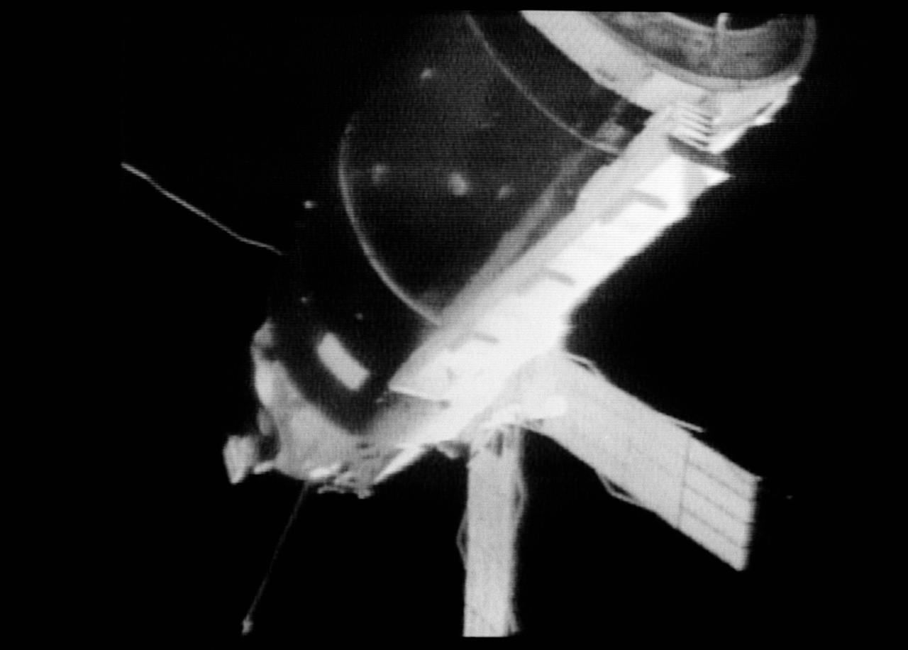
S73-27182 (25 May 1973) --- A close-up view of the Skylab 1 space station cluster can be seen in this reproduction taken from a color television transmission made by a TV camera aboard the Skylab 2 Command Module during its "fly around" inspection of the cluster. This view has been enhanced. At left center the damaged solar array system wing on the Orbital Workshop (OWS) appears to be partly folded. In their preliminary inspection the crewmen noted that portions of the micrometeoroid shield had slid back underneath the OWS solar wing. Solar panels on the Apollo Telescope Mount extend out at the top center. Photo credit: NASA
The Atmospheric Turbulence Measurement System booms are clearly evident in this view of the Pathfinder-Plus solar aircraft as it flies over Rogers Dry Lake.
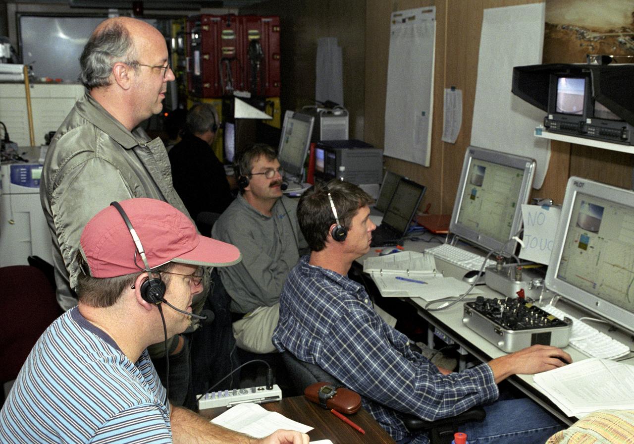
AeroVironment's test director Jim Daley, backup pilot Rik Meininger, stability and controls engineer Derek Lisoski and pilot Wyatt Sadler (clockwise from bottom left) closely monitor systems testing of the Pathfinder-Plus solar aircraft from the control station.
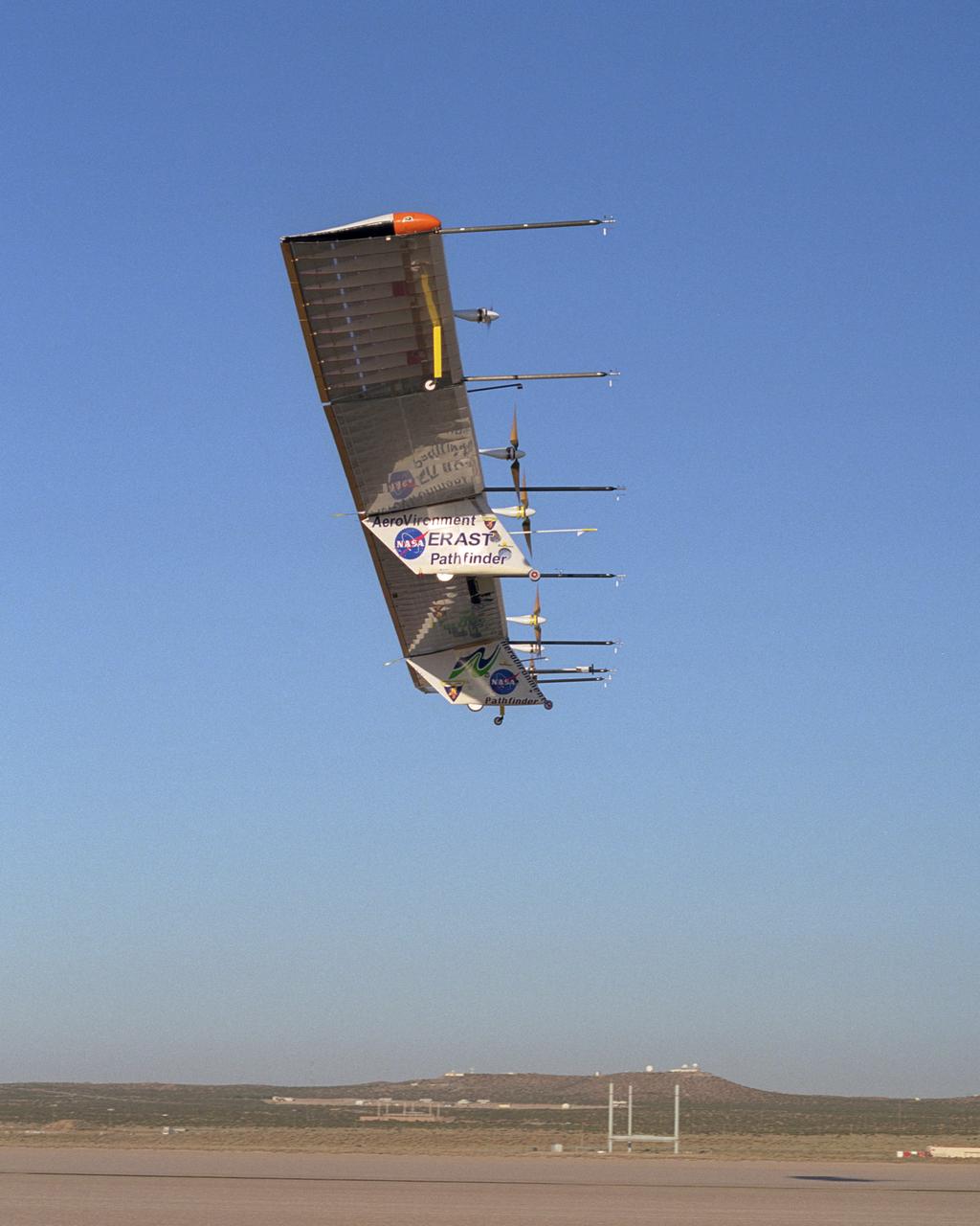
With turbulence-measurement booms projecting ahead of the wing, Pathfinder-Plus soars aloft over Rogers Dry Lake on its final research flight from NASA Dryden.
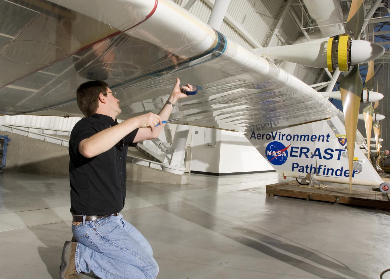
AeroVironment crew chief Mark Shipley applies sealing tape to a wing joint on Pathfinder-Plus before it is hoisted into place at the NASM's Udvar-Hazy Center.
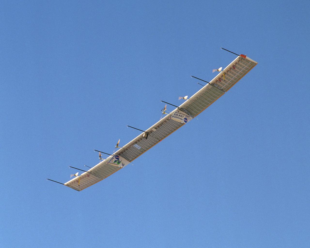
With its sensor booms projecting ahead of the wing, the Pathfinder-Plus solar-electric aircraft soars under a blue sky on a turbulence measurement research flight.
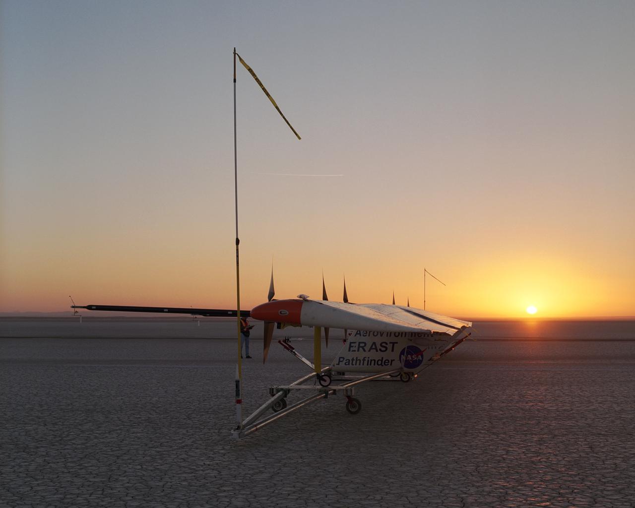
As the rising sun dawns over the parched bed of Rogers Dry Lake, AeroVironment's solar-electric Pathfinder-Plus awaits takeoff on its final research flight.
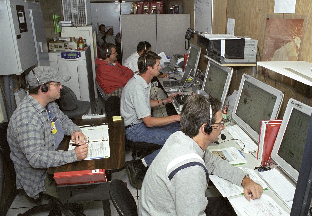
AeroVironment engineers and technicians closely monitor flight data in the ground control station during the Pathfinder-Plus' turbulence measurement flights.
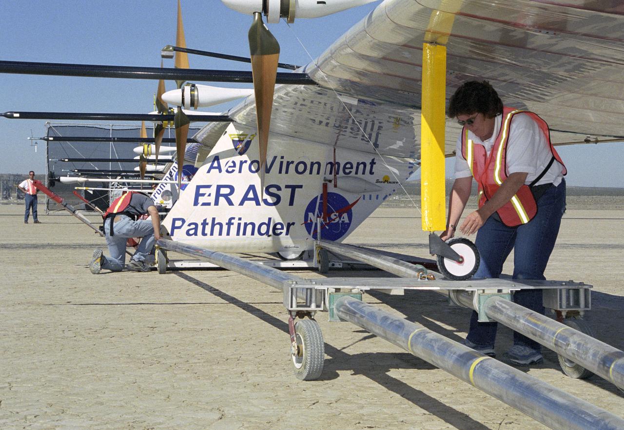
AeroVironment technicians prepare to remove the Pathfinder-Plus solar aircraft from its ground dolly before a turbulence measurement flight from Rogers Dry Lake.
KENNEDY SPACE CENTER, FLA. -- One of two fledgling ospreys still in the nest stretches its wings to fly away. The stick-built nest is located in the NASA KSC News Center parking lot. Ospreys select nesting sites of opportunity, from trees and telephone poles to rocks or even flat ground. In the United States they are found from Alaska to Florida and the Gulf Coast. Osprey nests are found throughout the Kennedy Space Center and nearby Merritt Island National Wildlife Refuge. Known as a fish hawk, ospreys often can be seen flying overhead with a fish in their talons. Fish are their sole source of food.
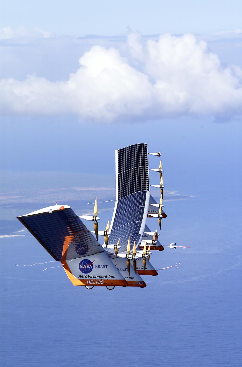
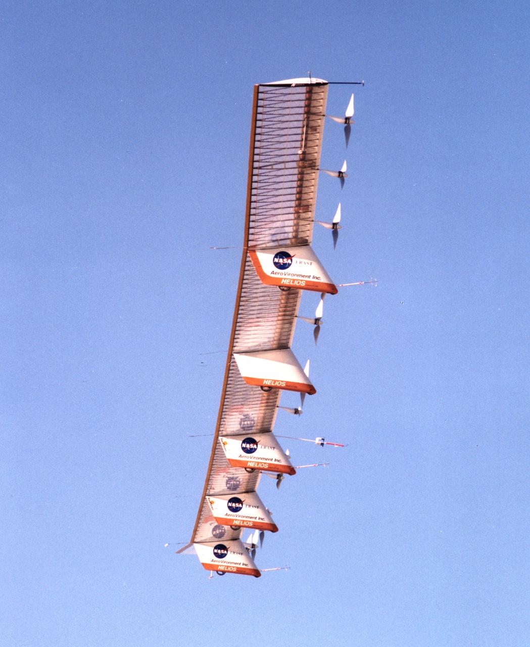
The solar-electric Helios Prototype flying wing is shown near the Hawaiian island of Niihau during its first test flight on solar power from the U.S. Navy's Pacific Missile Range Facility on Kauai, Hawaii, July 14, 2001. The 18-hour flight was a functional checkout of the aircraft's systems and performance in preparation for an attempt to reach sustained flight at 100,000 feet altitude later this summer.
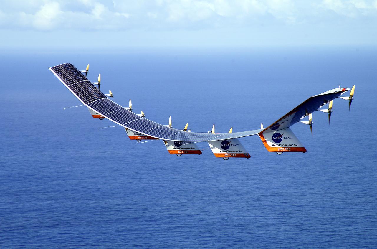
The solar-electric Helios Prototype flying wing is shown over the Pacific Ocean during its first test flight on solar power from the U.S. Navy's Pacific Missile Range Facility on Kauai, Hawaii, July 14, 2001. The 18-hour flight was a functional checkout of the aircraft's systems and performance in preparation for an attempt to reach sustained flight at 100,000 feet altitude later this summer.
The solar-electric Helios Prototype flying wing is shown near the Hawaiian island of Niihau during its first test flight on solar power from the U.S. Navy's Pacific Missile Range Facility on Kauai, Hawaii, July 14, 2001. The 18-hour flight was a functional checkout of the aircraft's systems and performance in preparation for an attempt to reach sustained flight at 100,000 feet altitude later this summer.
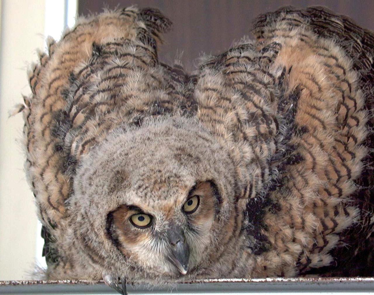
KENNEDY SPACE CENTER, FLA. -- A baby owl displays its wings at the photographer snapping its picture. The owl was found on the stairs inside Hangar G, Cape Canaveral Air Force Station. It had apparently tried to fly from a nest near the ceiling but couldn't get back to it. Workers called an Audubon rescue center near Orlando, which captured it and will ensure the bird is returned to the wild when it's ready.
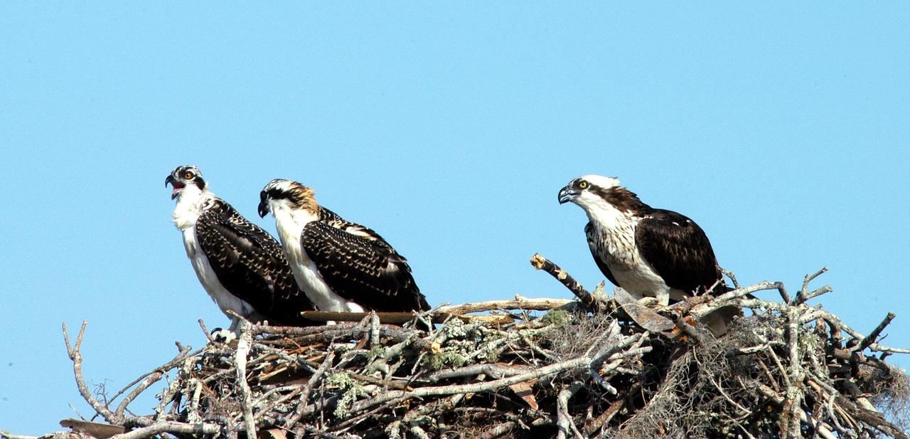
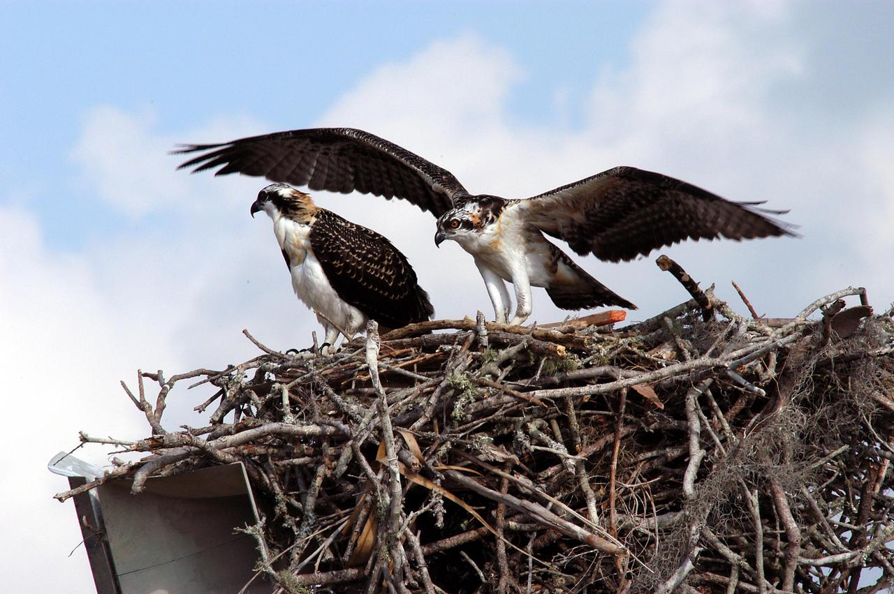
KENNEDY SPACE CENTER, FLA. -- - Three osprey fledglings are ready to test their wings from the nest at the NASA News Center parking lot. Ospreys select nesting sites of opportunity, from trees and telephone poles to rocks or even flat ground. In the United States they are found from Alaska to Florida and the Gulf Coast. Osprey nests are found throughout the Kennedy Space Center and nearby Merritt Island National Wildlife Refuge. Known as a fish hawk, ospreys often can be seen flying overhead with a fish in their talons.
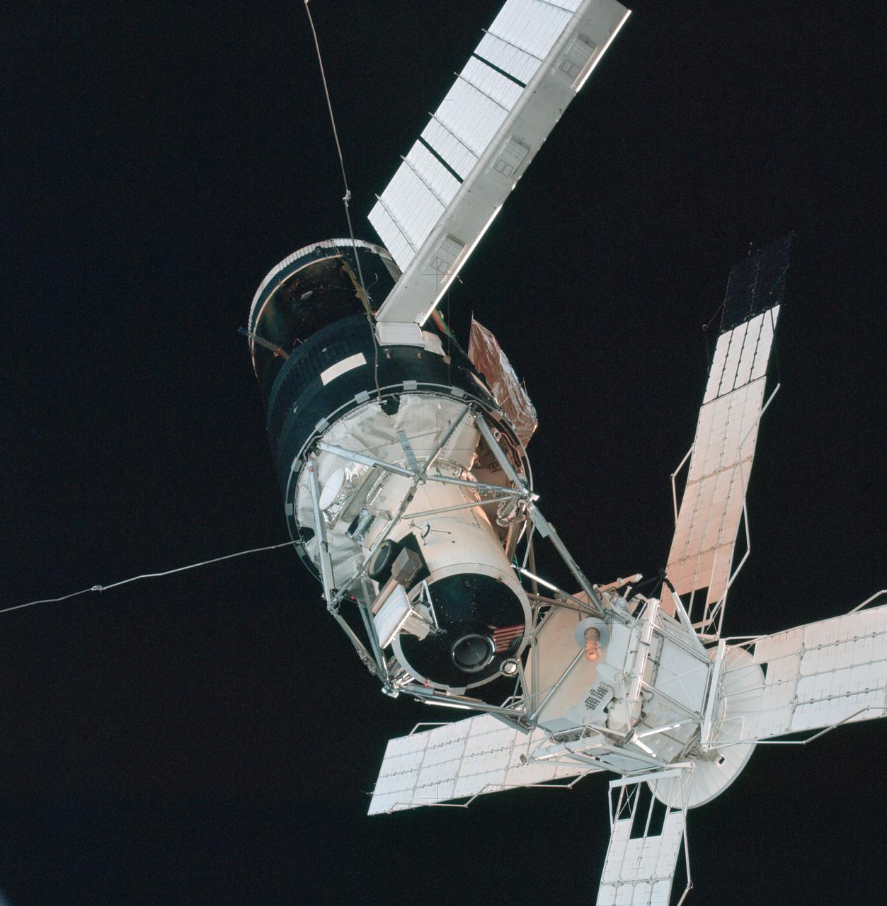
A close-up view of the Skylab space station cluster photographed against a black sky background from the Skylab 3 command module during the "fly around" inspection prior to docking. Note the one solar array system wing on the Orbital Workshop (OWS) which was successfully deployed during EVA on the first manned Skylab mission. The primary docking part at the forward end of the Multiple Docking Adapter (MDA) is visible below the Apollo Telescope Mount (ATM).
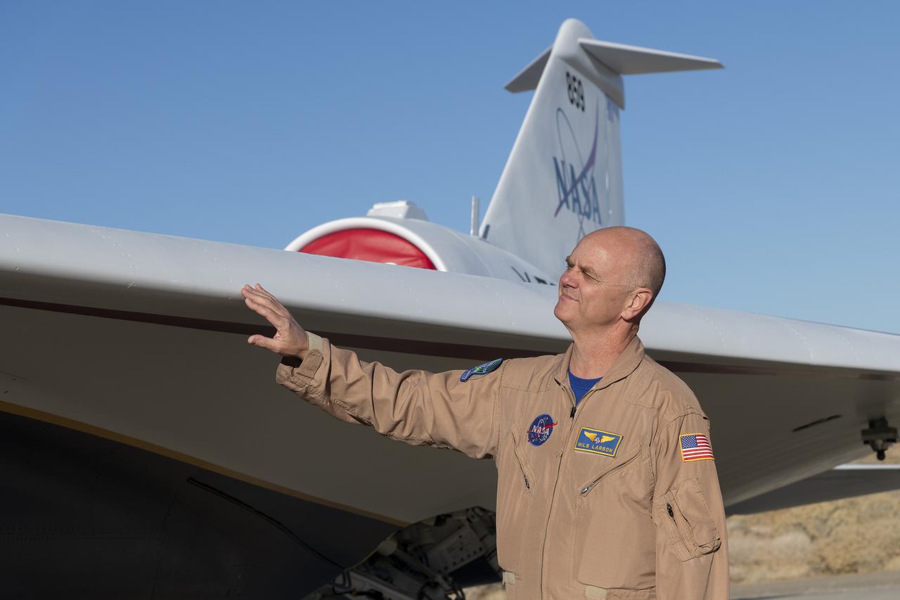
NASA test pilot Nils Larson gets an initial look at the painted X-59 as it sits on the ramp at Lockheed Martin Skunk Works in Palmdale, California. Larson, one of three test pilots training to fly the X-59 inspects aircraft’s delta wing; a requirement for quiet supersonic flight. The X-59 is the centerpiece of NASA’s Quesst mission, which seeks to solve one of the major barriers to supersonic flight over land, currently banned in the United States, by making sonic booms quieter.
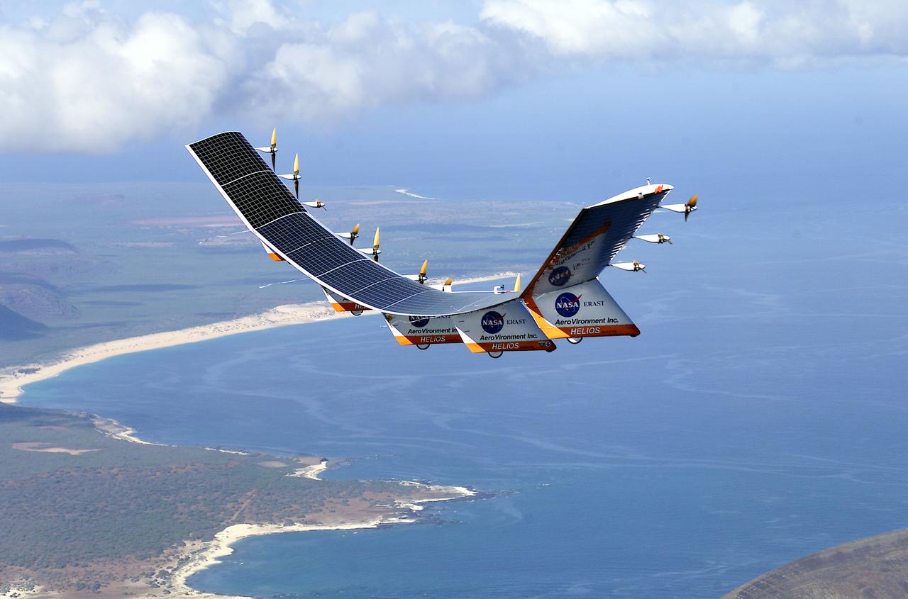
The solar-electric Helios Prototype flying wing is shown near the Hawaiian islands of Niihau and Lehua during its first test flight on solar power from the U.S. Navy's Pacific Missile Range Facility on Kauai, Hawaii, July 14, 2001. The 18-hour flight was a functional checkout of the aircraft's systems and performance in preparation for an attempt to reach sustained flight at 100,000 feet altitude later this summer.
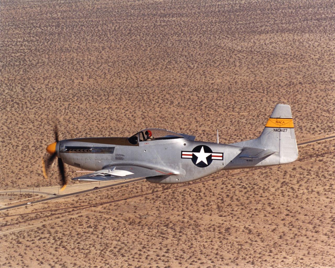
A white plate on the top of the wing of a restored National Advisory Committee for Aeronautics (NACA) P-51D Mustang mounts scale airfoil shapes as used by the NACA in the late 1940s for high-speed research. This former NACA testbed Mustang was rebuilt by John Muszala for Bill Allmon of Las Vegas, Nevada, who has been flying it since 1998. Allmon flew the vintage fighter to NASA's Dryden Flight Research Center at Edwards, California, Sept. 15, 2000 for a reunion of former NACA employees.
The solar-electric Helios Prototype flying wing is shown near the Hawaiian islands of Niihau and Lehua during its first test flight on solar power from the U.S. Navy's Pacific Missile Range Facility on Kauai, Hawaii, July 14, 2001. The 18-hour flight was a functional checkout of the aircraft's systems and performance in preparation for an attempt to reach sustained flight at 100,000 feet altitude later this summer.
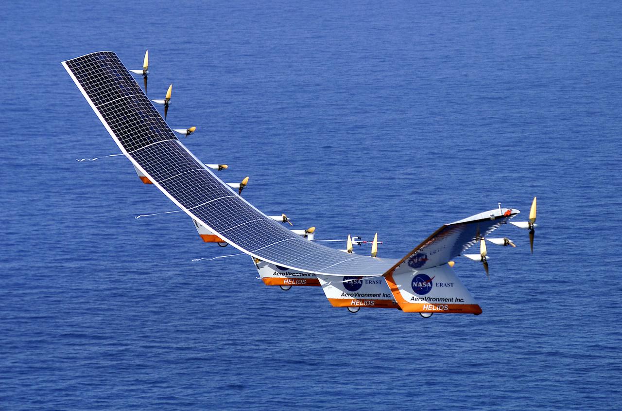
The solar-electric Helios Prototype flying wing is shown over the Pacific Ocean during its first test flight on solar power from the U.S. Navy's Pacific Missile Range Facility on Kauai, Hawaii, July 14, 2001. The 18-hour flight was a functional checkout of the aircraft's systems and performance in preparation for an attempt to reach sustained flight at 100,000 feet altitude later this summer.

KENNEDY SPACE CENTER, FLA. -- A baby owl displays its wings at the photographer snapping its picture. The owl was found on the stairs inside Hangar G, Cape Canaveral Air Force Station. It had apparently tried to fly from a nest near the ceiling but couldn't get back to it. Workers called an Audubon rescue center near Orlando, which captured it and will ensure the bird is returned to the wild when it's ready.
The solar-electric Helios Prototype flying wing is shown moments after takeoff, beginning its first test flight on solar power from the U.S. Navy's Pacific Missile Range Facility on Kauai, Hawaii, July 14, 2001. The 18-hour flight was a functional checkout of the aircraft's systems and performance in preparation for an attempt to reach sustained flight at 100,000 feet altitude later this summer.
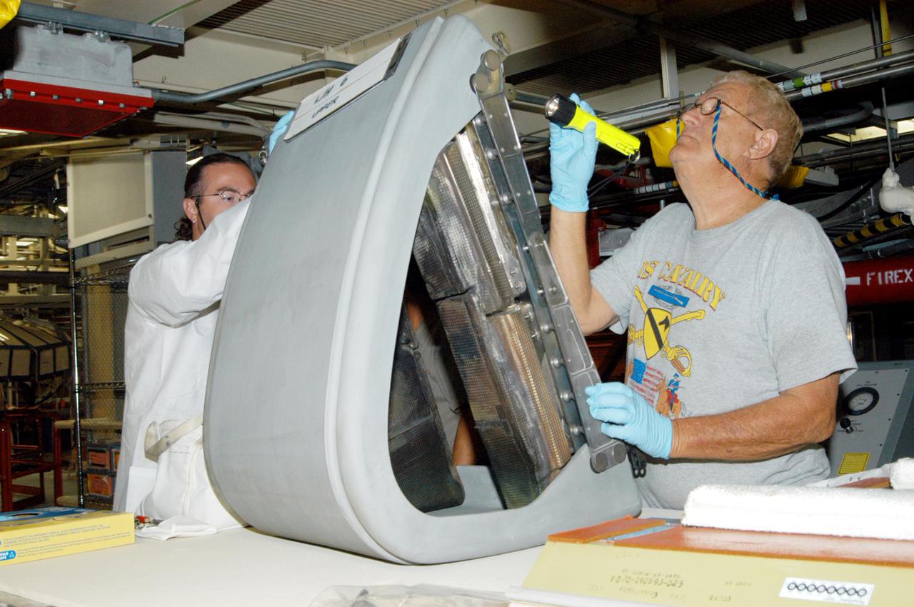
KENNEDY SPACE CENTER, FLA. - In the Orbiter Processing Facility, Matt Scott and Mel Romans (left and right), with United Space Alliance, closely inspect the final Reinforced Carbon-Carbon (RCC) panel to be installed on orbiter Discovery’s left wing. The leading edges of each of an orbiter’s wings have 22 RCC panels. They are light gray and made entirely of carbon composite material, which protect the orbiter during re-entry. The molded components are approximately 0.25- to 0.5-inch thick and capable of withstanding temperatures up to 3,220 degrees F. Following the Columbia accident in February 2002, which was caused by a breach in an RCC panel that allowed hot gases into the vehicle, each panel on Discovery was removed and thoroughly inspected before final reinstallation. Discovery is the designated orbiter to fly on the Return to Flight mission STS-114, the first Space Shuttle to launch since the accident. The launch window for the mission is May 12 to June 3, 2005.
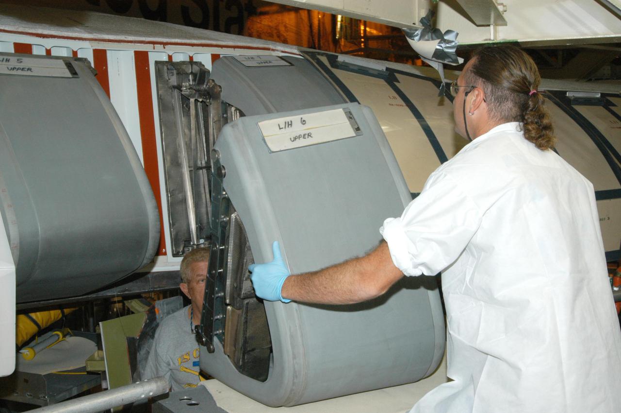
KENNEDY SPACE CENTER, FLA. - Matt Scott, with United Space Alliance, lifts the final Reinforced Carbon-Carbon (RCC) panel into position for installation on orbiter Discovery’s left wing. The leading edges of each of an orbiter’s wings have 22 RCC panels. They are light gray and made entirely of carbon composite material, which protect the orbiter during re-entry. The molded components are approximately 0.25- to 0.5-inch thick and capable of withstanding temperatures up to 3,220 degrees F. Following the Columbia accident in February 2002, which was caused by a breach in an RCC panel that allowed hot gases into the vehicle, each panel on Discovery was removed and thoroughly inspected before final reinstallation. Discovery is the designated orbiter to fly on the Return to Flight mission STS-114, the first Space Shuttle to launch since the accident. The launch window for the mission is May 12 to June 3, 2005.
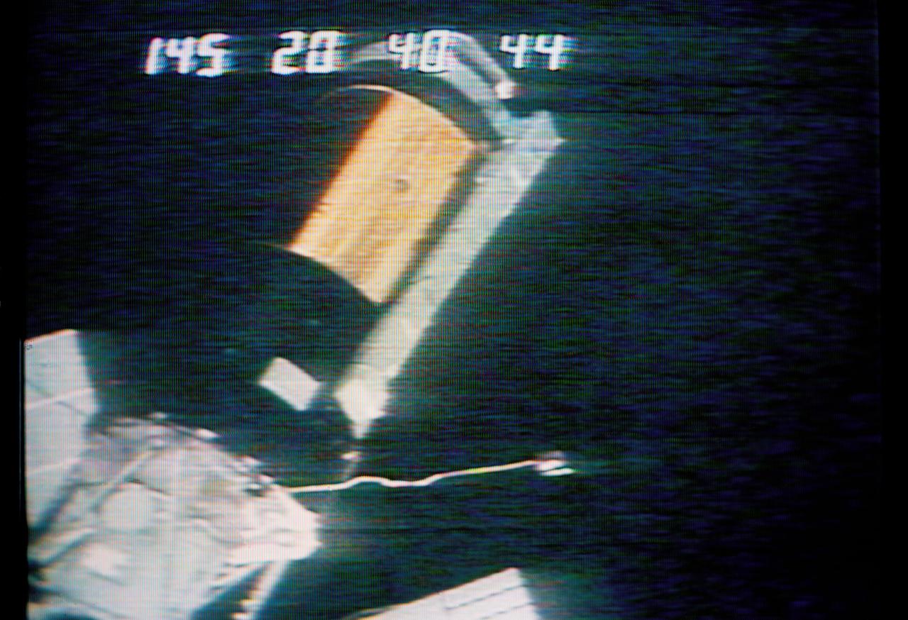
S73-26738 (25 May 1973) --- A close-up view of the Skylab 1 space station cluster can be seen in this reproduction taken from a color television transmission made by a TV camera aboard the Skylab 2 Command Module during its ?fly-around? inspection of the cluster. The numbers across the top of the picture indicate the Skylab 1 ground lapse time. Note the missing portion of the micrometeoroid shield on the Orbital Workshop. The shield area was reported to be solid gold by the Skylab 2 crewmen. A cable appears to be wrapped around the damaged OWS solar array system wing. The crewmen reported that the other OWS solar panel was completely gone, with only tubes and wiring sticking out. One of the discone antennas extends out form the Airlock Module. The Multiple Docking Adapter is in the lower left corner of the picture. A portion of a solar panel on the Apollo Telescope Mount is visible at the bottom and at the left edge. In their ?fly around? inspection the crewmen noted that portions of the micrometeoroid shield had slid back underneath the OWS solar wing. Photo credit: NASA
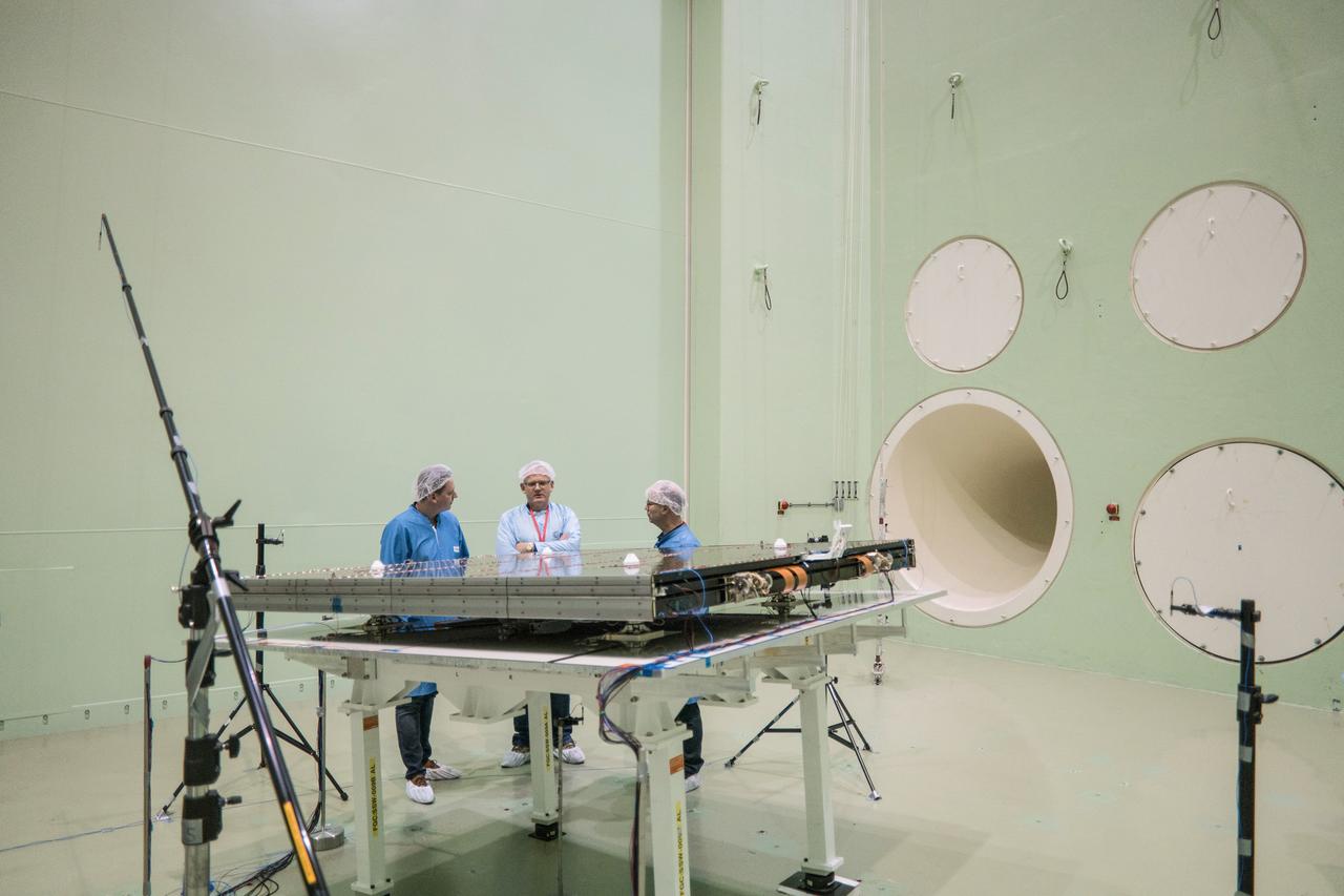
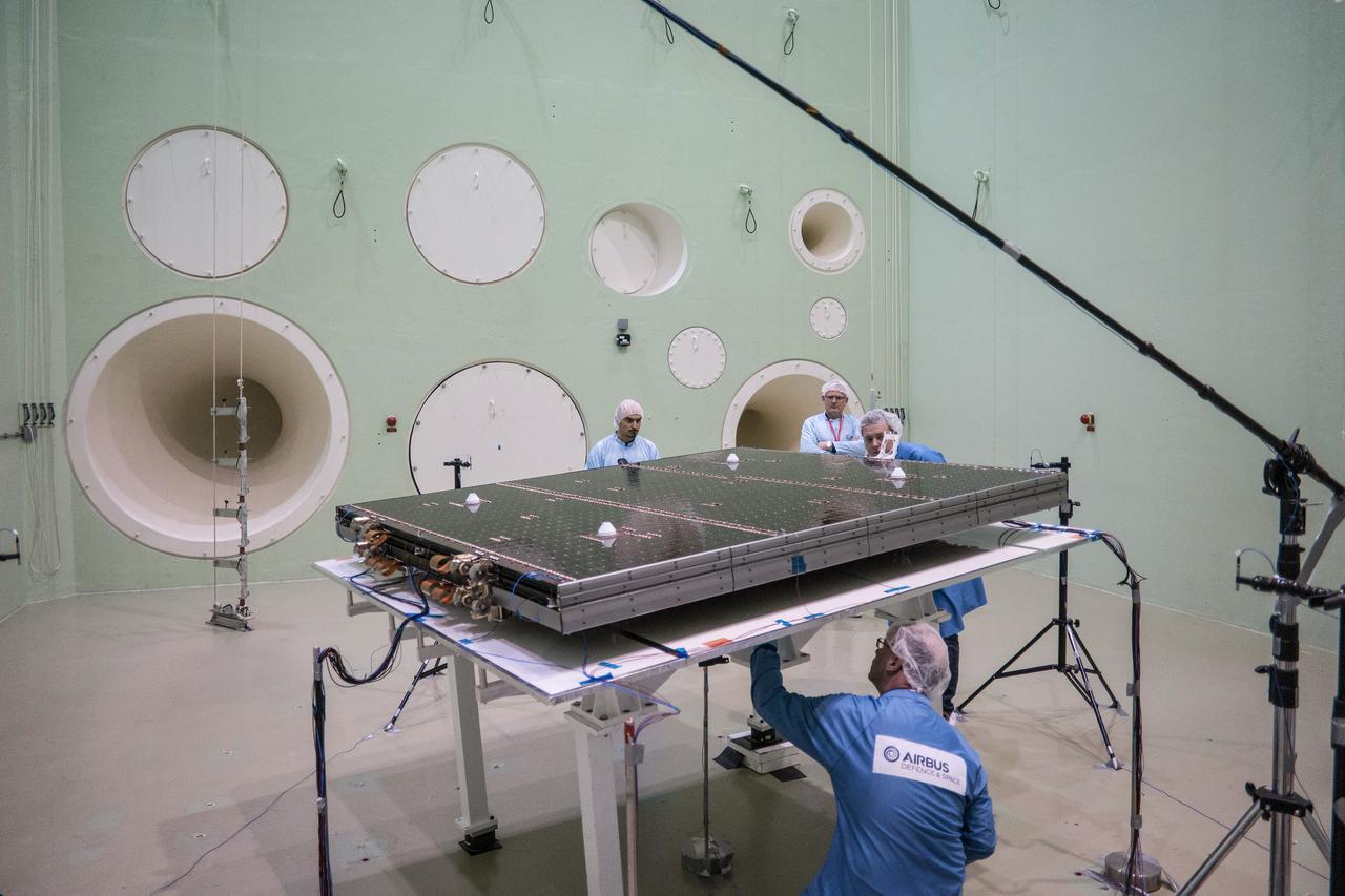
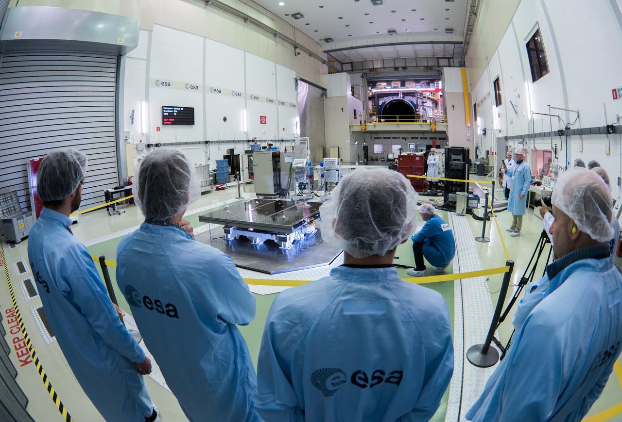
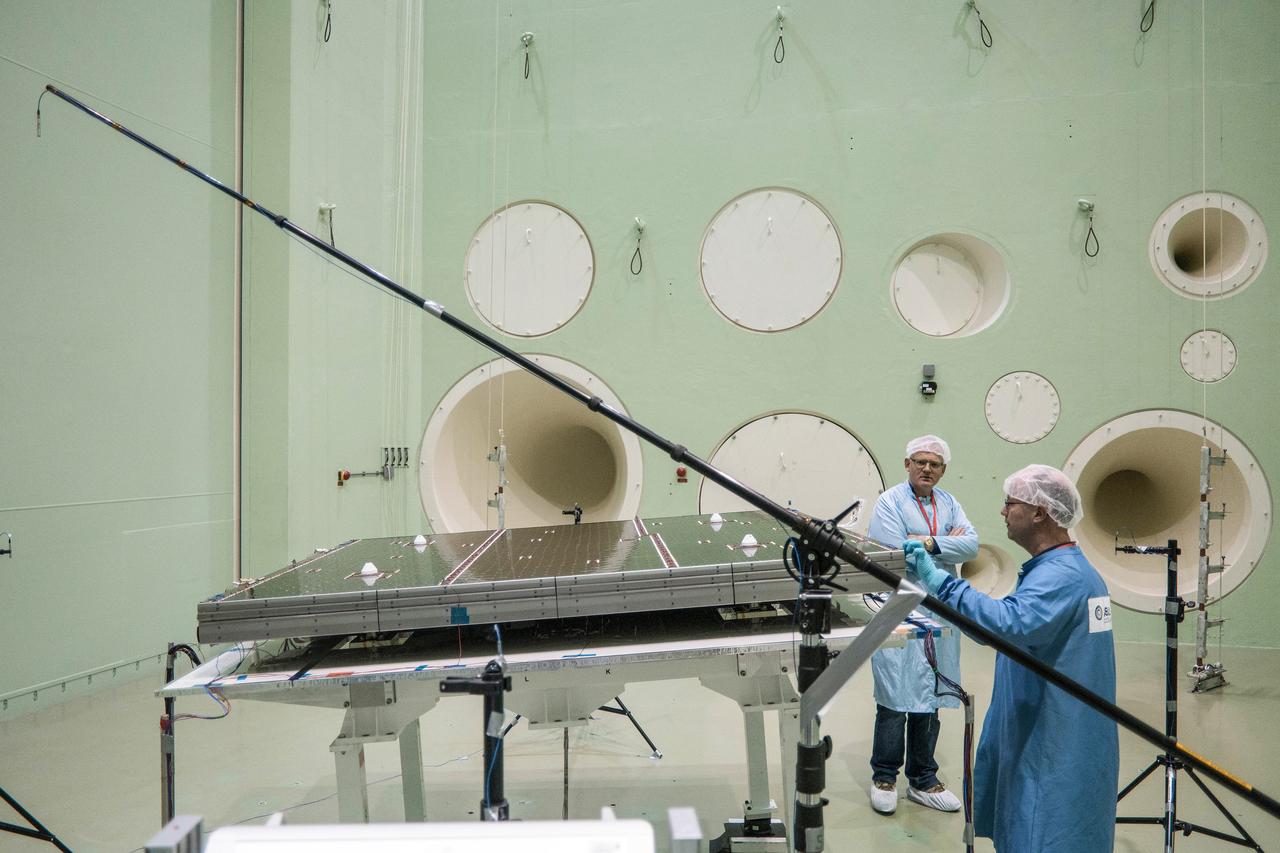
The solar arrays that will provide electricity to the Orion spacecraft were put through launch-day paces at ESA’s Test Centre in the Netherlands to verify that they can handle the rigours of the trip around the Moon... .The wings are seen here on April 11, 2018, on the shaking table that vibrates with the full force of a rumbling rocket. They were also placed in front of enormous speakers that recreate the harsh conditions they can expect on launch day. The solar arrays passed with flying colours... .The wings will be tested on how they deploy before shipping to Bremen, Germany, for integration with the European service module. ESA’s contribution to the Orion mission will provide power, propulsion, water, and air... .The first mission will take Orion around the Moon without astronauts. The solar panels will be folded inside the rocket fairing, once released from NASA’s Space Launch System rocket they will unfold and rotate towards the Sun to start delivering power... .With solar wings tested and fuel tanks installed, Orion is one step closer to its maiden voyage.
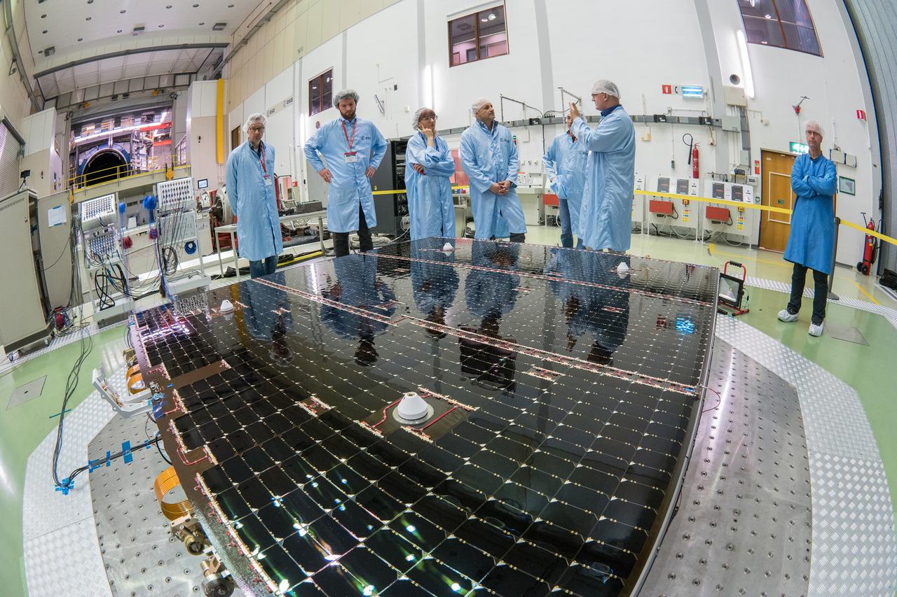
The solar arrays that will provide electricity to the Orion spacecraft were put through launch-day paces at ESA’s Test Centre in the Netherlands to verify that they can handle the rigours of the trip around the Moon... .The wings are seen here on April 11, 2018, on the shaking table that vibrates with the full force of a rumbling rocket. They were also placed in front of enormous speakers that recreate the harsh conditions they can expect on launch day. The solar arrays passed with flying colours... .The wings will be tested on how they deploy before shipping to Bremen, Germany, for integration with the European service module. ESA’s contribution to the Orion mission will provide power, propulsion, water, and air... .The first mission will take Orion around the Moon without astronauts. The solar panels will be folded inside the rocket fairing, once released from NASA’s Space Launch System rocket they will unfold and rotate towards the Sun to start delivering power... .With solar wings tested and fuel tanks installed, Orion is one step closer to its maiden voyage.
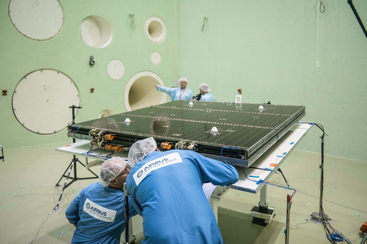
The solar arrays that will provide electricity to the Orion spacecraft were put through launch-day paces at ESA’s Test Centre in the Netherlands to verify that they can handle the rigours of the trip around the Moon... .The wings are seen here on April 11, 2018, on the shaking table that vibrates with the full force of a rumbling rocket. They were also placed in front of enormous speakers that recreate the harsh conditions they can expect on launch day. The solar arrays passed with flying colours... .The wings will be tested on how they deploy before shipping to Bremen, Germany, for integration with the European service module. ESA’s contribution to the Orion mission will provide power, propulsion, water, and air... .The first mission will take Orion around the Moon without astronauts. The solar panels will be folded inside the rocket fairing, once released from NASA’s Space Launch System rocket they will unfold and rotate towards the Sun to start delivering power... .With solar wings tested and fuel tanks installed, Orion is one step closer to its maiden voyage.
The solar arrays that will provide electricity to the Orion spacecraft were put through launch-day paces at ESA’s Test Centre in the Netherlands to verify that they can handle the rigours of the trip around the Moon... .The wings are seen here on April 11, 2018, on the shaking table that vibrates with the full force of a rumbling rocket. They were also placed in front of enormous speakers that recreate the harsh conditions they can expect on launch day. The solar arrays passed with flying colours... .The wings will be tested on how they deploy before shipping to Bremen, Germany, for integration with the European service module. ESA’s contribution to the Orion mission will provide power, propulsion, water, and air... .The first mission will take Orion around the Moon without astronauts. The solar panels will be folded inside the rocket fairing, once released from NASA’s Space Launch System rocket they will unfold and rotate towards the Sun to start delivering power... .With solar wings tested and fuel tanks installed, Orion is one step closer to its maiden voyage.
At Dryden Flight Research Center, Calif., KSC technician James Niehoff Jr. (left) helps attach the wing of the modified X-34, known as A-1A. Niehoff is one of eight NASA engineering technicians from KSC's Engineering Prototype Lab who have assisted Orbital Sciences Corporation and Dryden in the complex process of converting the X-34 A-1 vehicle from captive carry status to unpowered flight status, the A-1A. The other KSC technicians are Kevin Boughner, Roger Cartier, Mike Dininny, Mike Lane, Jerry Moscoso, David Rowell and Bryan Taylor. The X-34 is 58.3 feet long, 27.7 feet wide from wing tip to wing tip, and 11.5 feet tall from the bottom of the fuselage to the top of the tail. The autonomously operated technology demonstrator will be air-launched from an L-1011 airplane and should be capable of flying eight times the speed of sound, reaching an altitude of 250,000 feet. The X-34 Project is managed by NASA's Marshall Space Flight Center in Huntsville, Ala
The solar arrays that will provide electricity to the Orion spacecraft were put through launch-day paces at ESA’s Test Centre in the Netherlands to verify that they can handle the rigours of the trip around the Moon... .The wings are seen here on April 11, 2018, on the shaking table that vibrates with the full force of a rumbling rocket. They were also placed in front of enormous speakers that recreate the harsh conditions they can expect on launch day. The solar arrays passed with flying colours... .The wings will be tested on how they deploy before shipping to Bremen, Germany, for integration with the European service module. ESA’s contribution to the Orion mission will provide power, propulsion, water, and air... .The first mission will take Orion around the Moon without astronauts. The solar panels will be folded inside the rocket fairing, once released from NASA’s Space Launch System rocket they will unfold and rotate towards the Sun to start delivering power... .With solar wings tested and fuel tanks installed, Orion is one step closer to its maiden voyage.
KSC technician David Rowell works on the wing of the modified X-34, known as A-1A, at the Dryden Flight Research Center, Calif. Looking on are Art Cape, with Dryden, and Mike Brainard, with Orbital Sciences Corporation. Rowell is one of eight NASA engineering technicians from KSC's Engineering Prototype Lab who have assisted Orbital and Dryden in the complex process of converting the X-34 A-1 vehicle from captive carry status to unpowered flight status, the A-1A. The other KSC technicians are Kevin Boughner, Roger Cartier, Mike Dininny, Mike Lane, Jerry Moscoso, James Niehoff Jr. and Bryan Taylor. The X-34 is 58.3 feet long, 27.7 feet wide from wing tip to wing tip, and 11.5 feet tall from the bottom of the fuselage to the top of the tail. The autonomously operated technology demonstrator will be air-launched from an L-1011 airplane and should be capable of flying eight times the speed of sound, reaching an altitude of 250,000 feet. The X-34 Project is managed by NASA's Marshall Space Flight Center in Huntsville, Ala
The solar arrays that will provide electricity to the Orion spacecraft were put through launch-day paces at ESA’s Test Centre in the Netherlands to verify that they can handle the rigours of the trip around the Moon... .The wings are seen here on April 11, 2018, on the shaking table that vibrates with the full force of a rumbling rocket. They were also placed in front of enormous speakers that recreate the harsh conditions they can expect on launch day. The solar arrays passed with flying colours... .The wings will be tested on how they deploy before shipping to Bremen, Germany, for integration with the European service module. ESA’s contribution to the Orion mission will provide power, propulsion, water, and air... .The first mission will take Orion around the Moon without astronauts. The solar panels will be folded inside the rocket fairing, once released from NASA’s Space Launch System rocket they will unfold and rotate towards the Sun to start delivering power... .With solar wings tested and fuel tanks installed, Orion is one step closer to its maiden voyage.

The takeoff set the stage for a two-day Helios endurance flight in the stratosphere planned for mid-July. The Helios wing, spanning 247 feet and weighing about 2,400 pounds, is giving NASA and industry engineers confidence that remotely piloted aircraft will be able to stay aloft for weeks at a time, providing environmental monitoring capabilities and telecommunications relay services Helios is an all-electric airplane. In addition to being non-polluting, Helios can fly above storms, and use the power of the sun to stay aloft during daylight. Key to the success of this type of aircraft is the ability to fly in darkness, using fuel cells when sunlight cannot furnish energy. Helios flew over the Navy's Pacific Missile Range Facility where favorable sun exposure and test ranges closed to other air traffic benefited the NASA research effort. In 2003 the aircraft was lost to a crash.
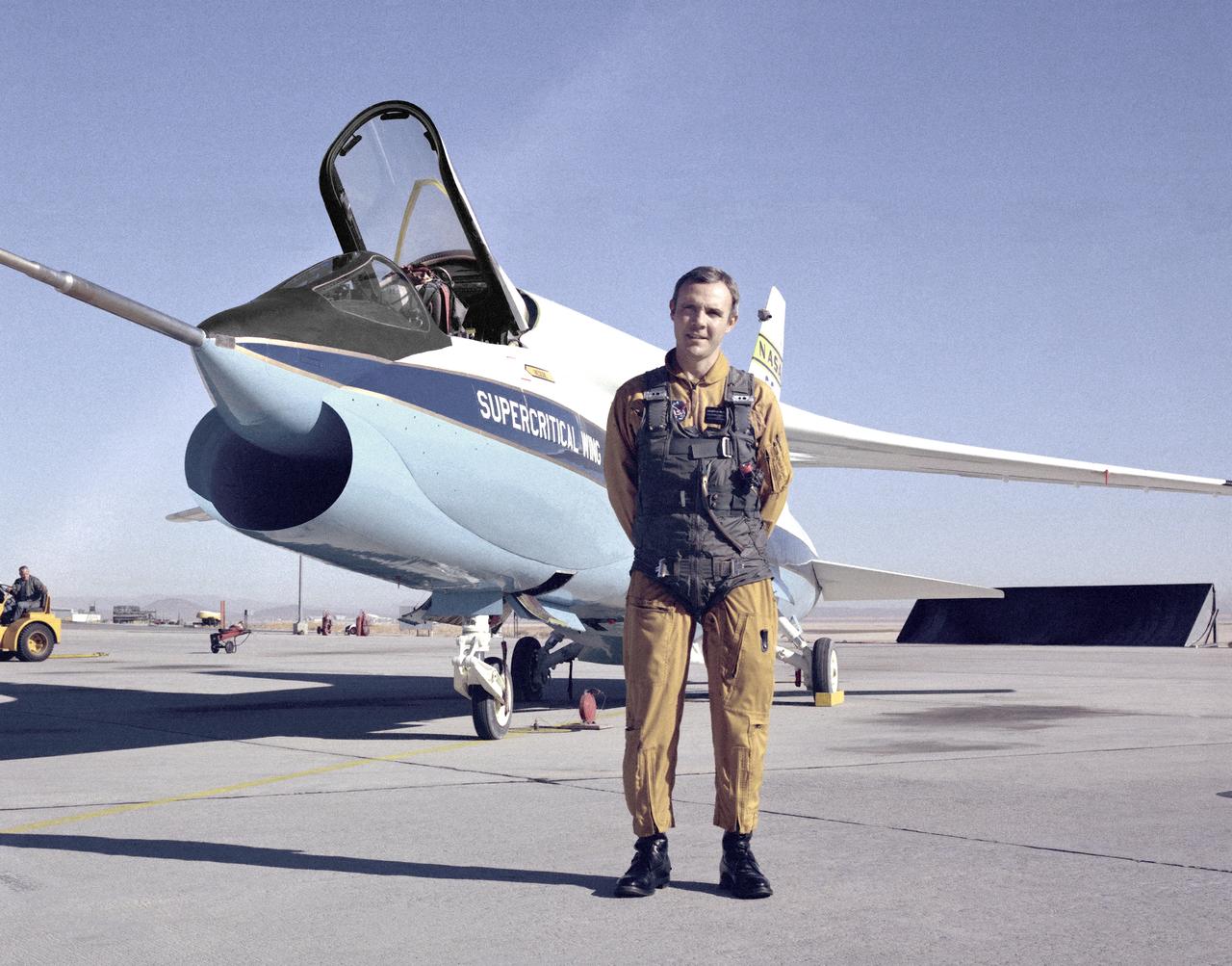
A Vought F-8A Crusader was selected by NASA as the testbed aircraft (designated TF-8A) to install an experimental Supercritical Wing (SCW) in place of the conventional wing. The unique design of the Supercritical Wing reduces the effect of shock waves on the upper surface near Mach 1, which in turn reduces drag. In this photograph the TF-8A Crusader with Supercritical Wing is shown on the ramp with project pilot Tom McMurtry standing beside it. McMurtry received NASA's Exceptional Service Medal for his work on the F-8 SCW aircraft. He also flew the AD-1, F-15 Digital Electronic Engine Control, the KC-130 winglets, the F-8 Digital Fly-By-Wire and other flight research aircraft including the remotely piloted 720 Controlled Impact Demonstration and sub-scale F-15 research projects. In addition, McMurtry was the 747 co-pilot for the Shuttle Approach and Landing Tests and made the last glide flight in the X-24B. McMurtry was Dryden’s Director for Flight Operations from 1986 to 1998, when he became Associate Director for Operations at NASA Dryden. In 1982, McMurtry received the Iven C. Kincheloe Award from the Society of Experimental Test Pilots for his contributions as project pilot on the AD-1 Oblique Wing program. In 1998 he was named as one of the honorees at the Lancaster, Calif., ninth Aerospace Walk of Honor ceremonies. In 1999 he was awarded the NASA Distinguished Service Medal. He retired in 1999 after a distinguished career as pilot and manager at Dryden that began in 1967.
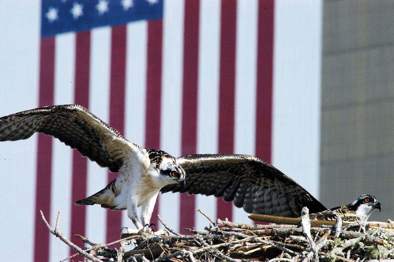
KENNEDY SPACE CENTER, FLA. -- One of three osprey fledglings spreads its wings, anticipating flight. The nest is in the NASA News Center parking lot, across from the Vehicle Assembly Building, with its 209-foot-high American flag painted on the south side. Ospreys select nesting sites of opportunity, from trees and telephone poles to rocks or even flat ground. In the United States they are found from Alaska to Florida and the Gulf Coast. Osprey nests are found throughout the Kennedy Space Center and nearby Merritt Island National Wildlife Refuge. Known as a fish hawk, ospreys often can be seen flying overhead with a fish in their talons.
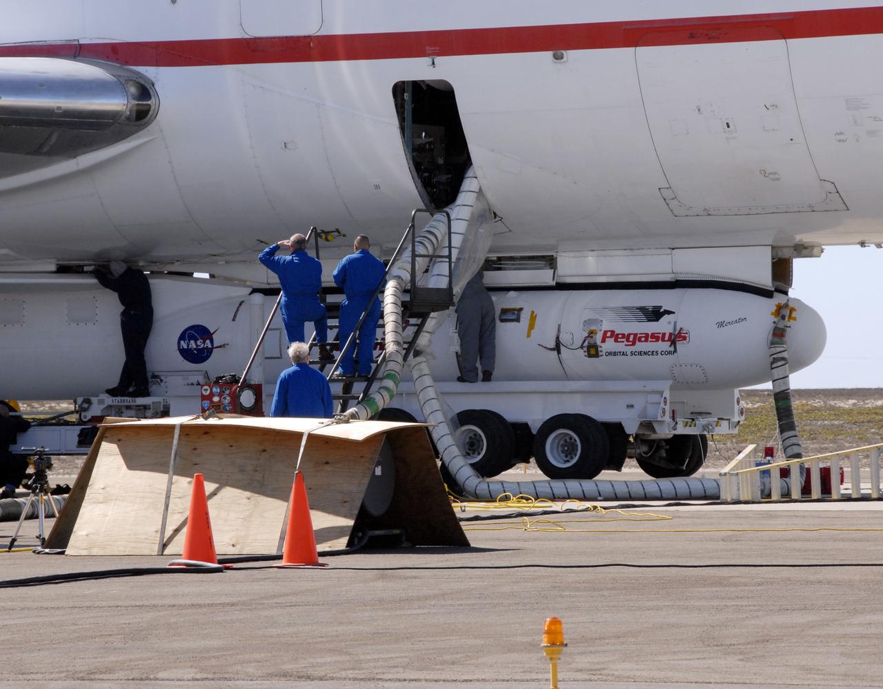
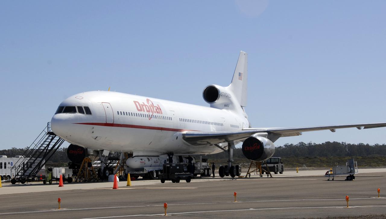
VANDENBERG AIR FORCE BASE, Fla. -- NASA’s Interstellar Boundary Explorer, or IBEX, spacecraft and mated Pegasus XL rocket are being attached to Orbital Sciences’ L-1011 aircraft for launch. IBEX is targeted for launch from the Kwajalein Atoll, a part of the Marshall Islands in the Pacific Ocean, on Oct. 19. IBEX will be launched aboard the Pegasus rocket dropped from under the wing of the L-1011 aircraft flying over the Pacific Ocean. The Pegasus will carry the spacecraft approximately 130 miles above Earth and place it in orbit. The IBEX satellite will make the first map of the boundary between the Solar System and interstellar space. Photo credit: NASA/Mark Mackley, VAFB
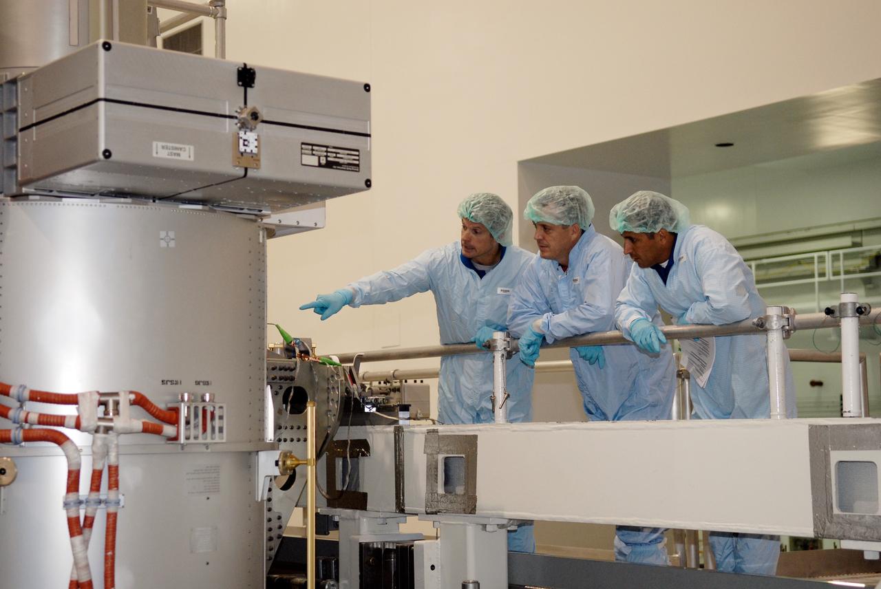
CAPE CANAVERAL, Fla. – In the Space Station Processing Facility at NASA's Kennedy Space Center, from left, STS-119 Mission Specialists Steve Swanson, Richard Arnold and Joseph Acaba inspect hardware slated to fly on their upcoming space shuttle mission. On the STS-119 mission, space shuttle Discovery will carry the S6 truss segment to complete the 361-foot-long backbone of the International Space Station. The truss includes the fourth pair of solar array wings and electronics that convert sunlight to power for the orbiting laboratory. Launch is targeted for Feb. 12, 2009. Photo credit: NASA/Kim Shiflett
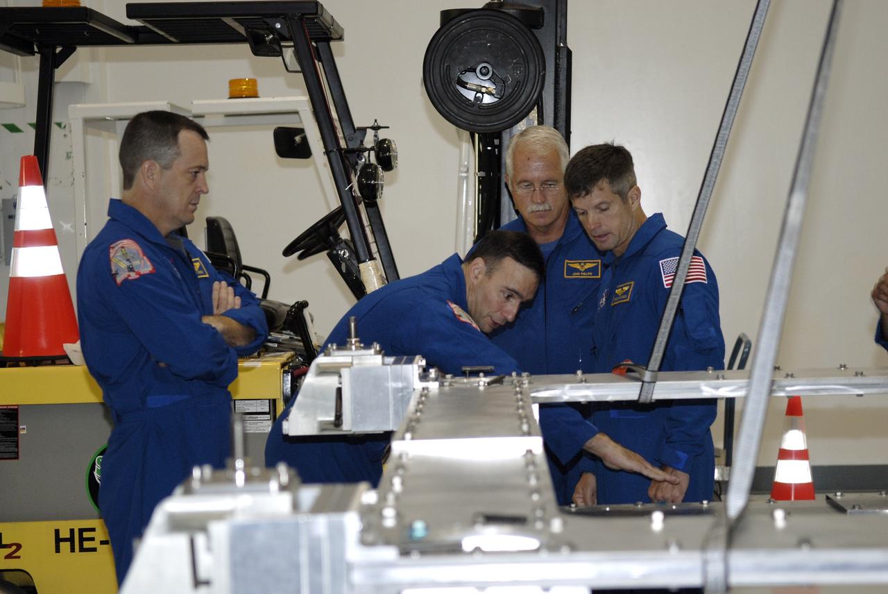
CAPE CANAVERAL, Fla. – In the Space Station Processing Facility at NASA's Kennedy Space Center, from left, STS-119 Mission Specialist Richard Arnold, Commander Lee Archambault, and Mission Specialists John Phillips and Steve Swanson familiarize themselves with hardware slated to fly on their upcoming space shuttle mission. On the STS-119 mission, space shuttle Discovery will carry the S6 truss segment to complete the 361-foot-long backbone of the International Space Station. The truss includes the fourth pair of solar array wings and electronics that convert sunlight to power for the orbiting laboratory. Launch is targeted for Feb. 12, 2009. Photo credit: NASA/Kim Shiflett
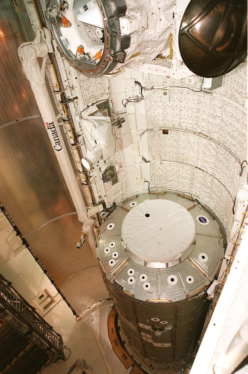
KENNEDY SPACE CENTER, FLA. -- In this view from Level 5, wing platform, of Atlantis’ payload bay, the U.S. Lab Destiny can be seen near the bottom. A key element in the construction of the International Space Station, Destiny is 28 feet long and weighs 16 tons. Destiny will be attached to the Unity node of the ISS using the Shuttle’s robot arm, seen here on the left with the help of an elbow camera, facing left. Measurements of the elbow camera revealed only a one-inch clearance from the U.S. Lab payload, which is under review. Destiny will fly on STS-98, the seventh construction flight to the ISS. Launch of STS-98 is scheduled for Jan. 19 at 2:11 a.m. EST
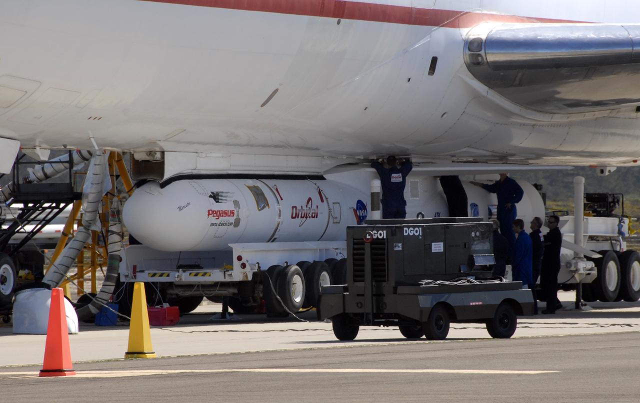
VANDENBERG AIR FORCE BASE, Fla. -- NASA’s Interstellar Boundary Explorer, or IBEX, spacecraft and mated Pegasus XL rocket are being attached to Orbital Sciences’ L-1011 aircraft for launch. IBEX is targeted for launch from the Kwajalein Atoll, a part of the Marshall Islands in the Pacific Ocean, on Oct. 19. IBEX will be launched aboard the Pegasus rocket dropped from under the wing of the L-1011 aircraft flying over the Pacific Ocean. The Pegasus will carry the spacecraft approximately 130 miles above Earth and place it in orbit. The IBEX satellite will make the first map of the boundary between the Solar System and interstellar space. Photo credit: NASA/Mark Mackley, VAFB
VANDENBERG AIR FORCE BASE, Fla. -- NASA’s Interstellar Boundary Explorer, or IBEX, spacecraft and mated Pegasus XL rocket are being attached to Orbital Sciences’ L-1011 aircraft for launch. IBEX is targeted for launch from the Kwajalein Atoll, a part of the Marshall Islands in the Pacific Ocean, on Oct. 19. IBEX will be launched aboard the Pegasus rocket dropped from under the wing of the L-1011 aircraft flying over the Pacific Ocean. The Pegasus will carry the spacecraft approximately 130 miles above Earth and place it in orbit. The IBEX satellite will make the first map of the boundary between the Solar System and interstellar space. Photo credit: NASA/Mark Mackley, VAFB
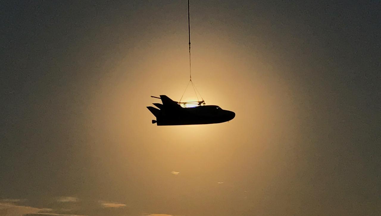
Sierra Nevada Corporation’s Dream Chaser completed an important step toward orbital flight with a successful captive carry test at NASA’s Armstrong Flight Research Center in California, located on Edwards Air Force Base. A helicopter successfully carried a Dream Chaser test article, which has the same specifications as a flight-ready spacecraft, to the same altitude and flight conditions of an upcoming free flight test. The Dream Chaser is a lifting-body, winged spacecraft that will fly back to Earth in a manner similar to NASA’s space shuttles. The successful captive carry test clears the way for a free flight test of the spacecraft later this year in which the uncrewed Dream Chaser will be released to glide on its own and land.