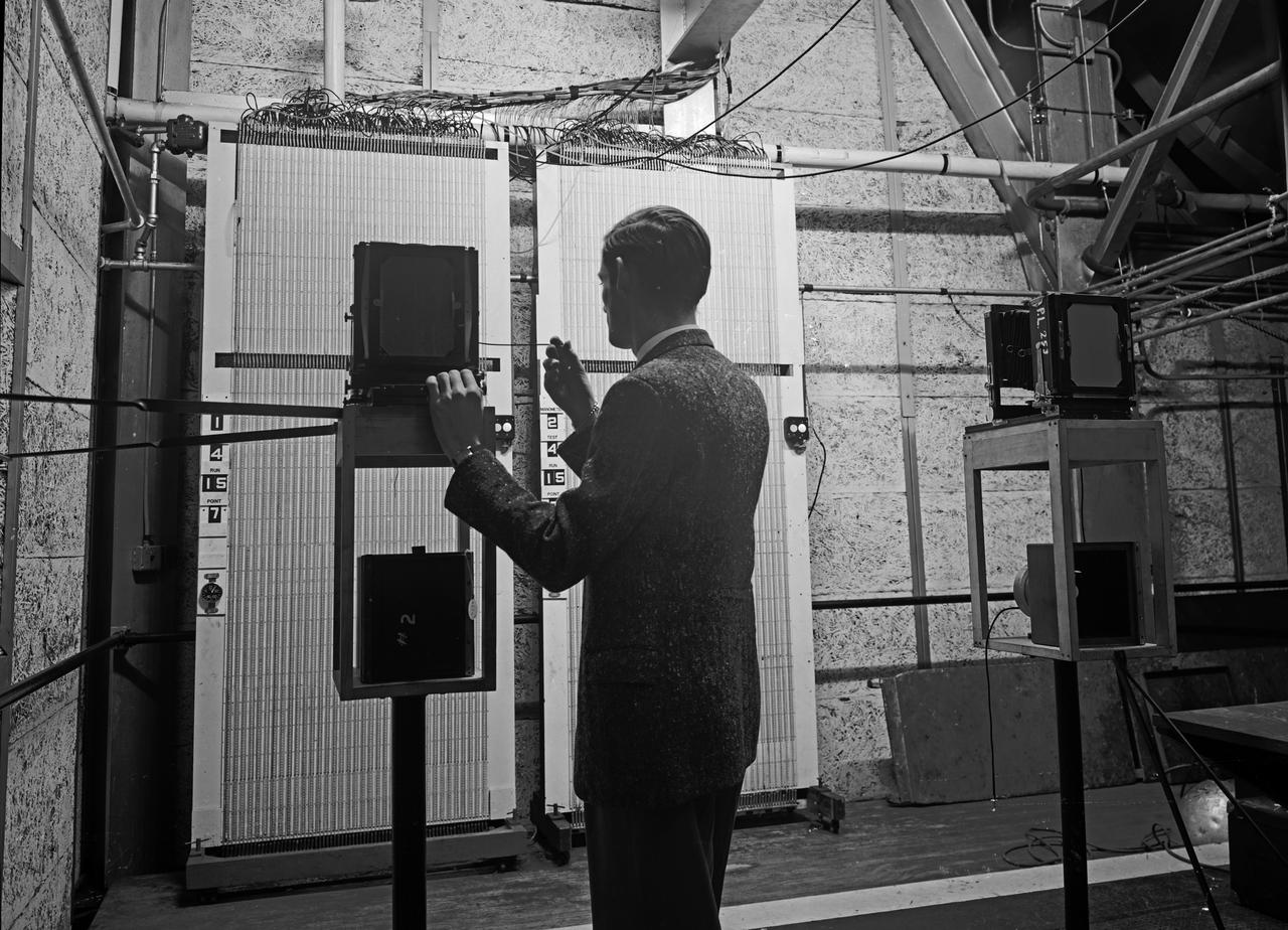
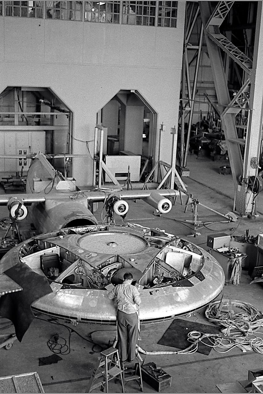
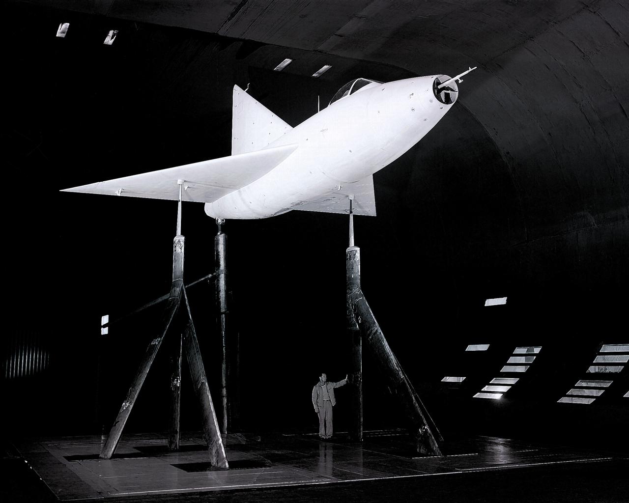
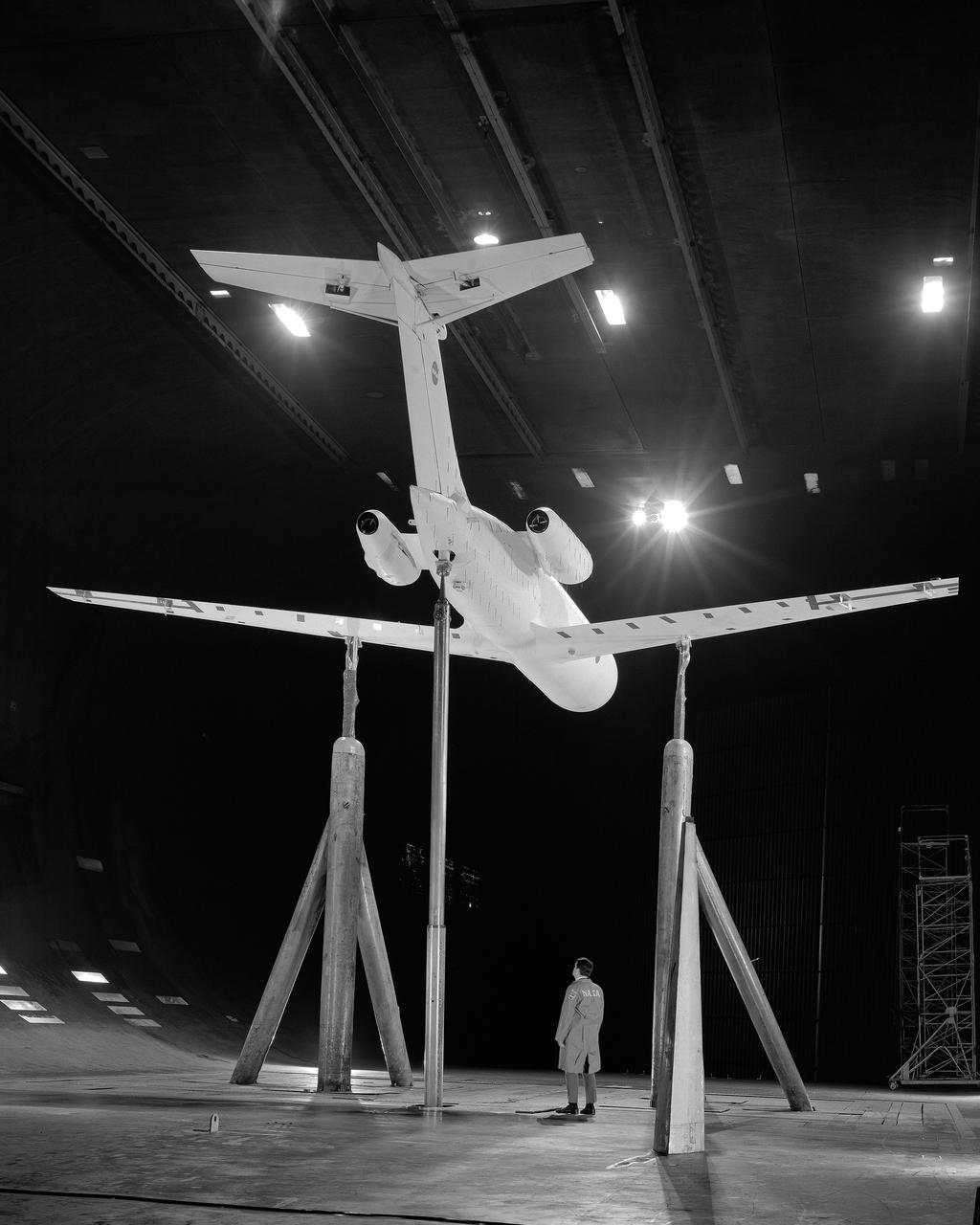
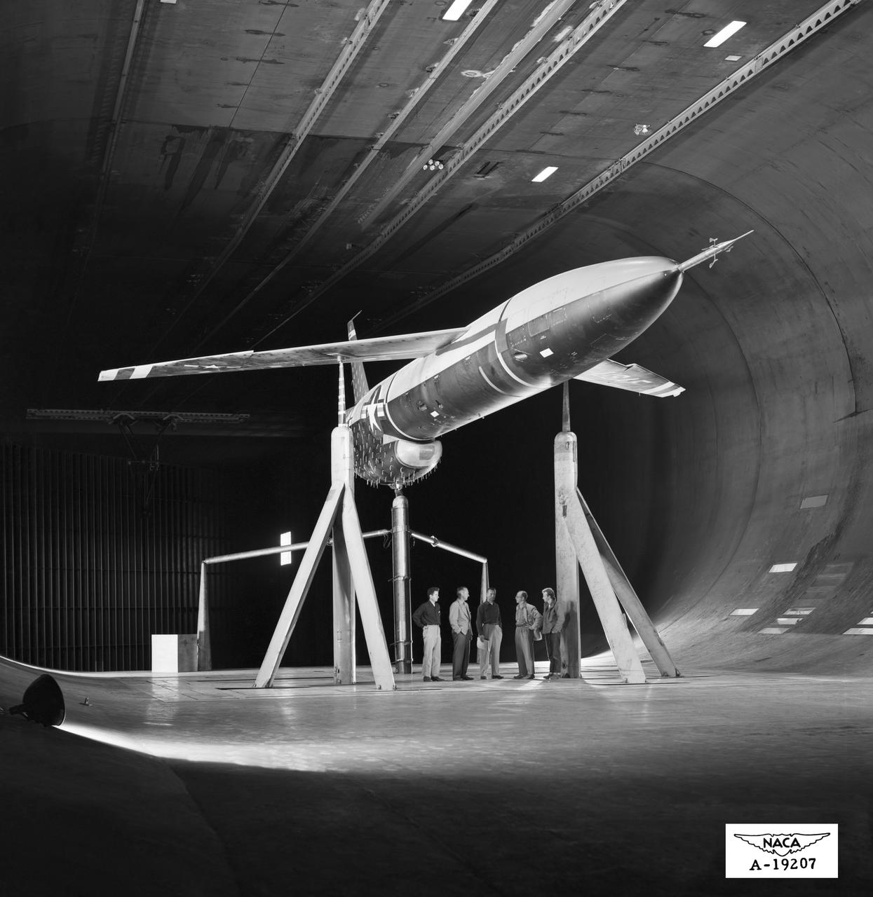
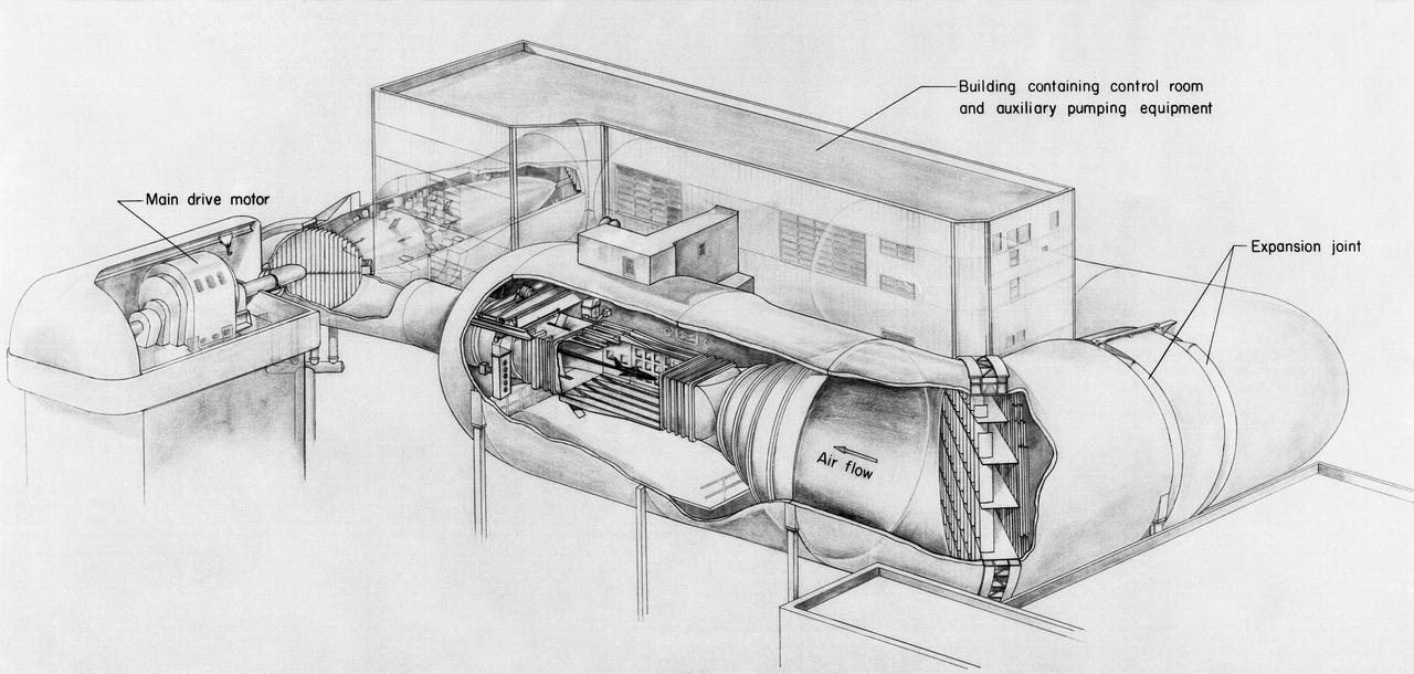
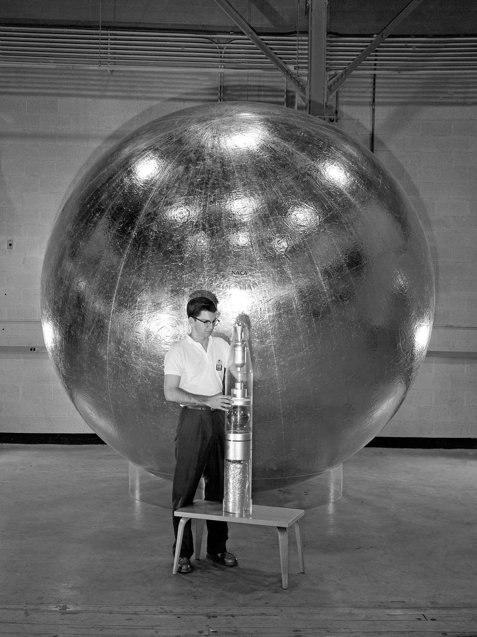
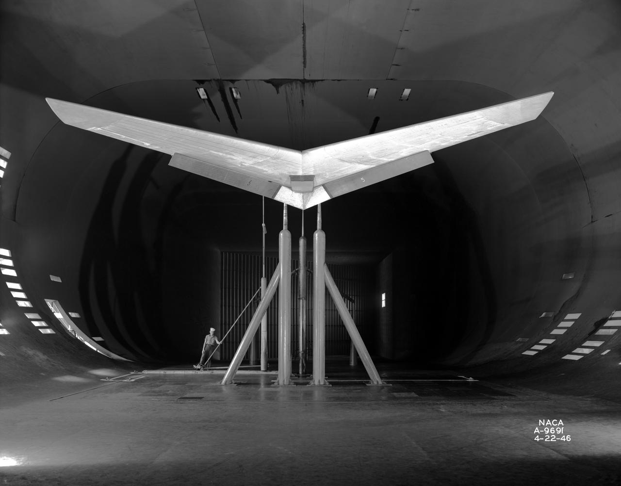
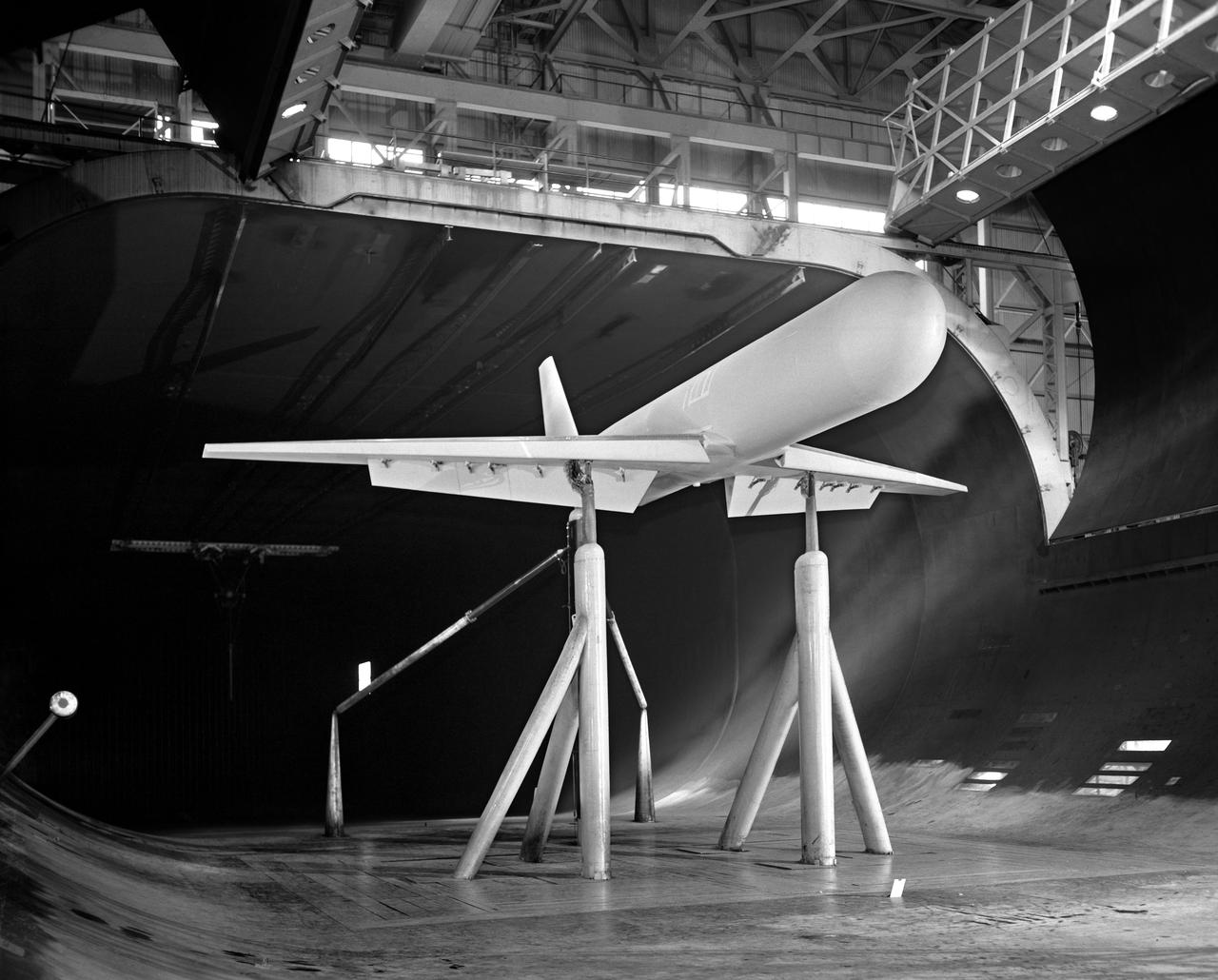
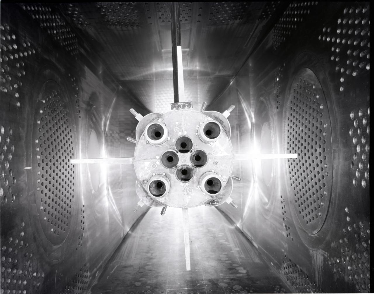
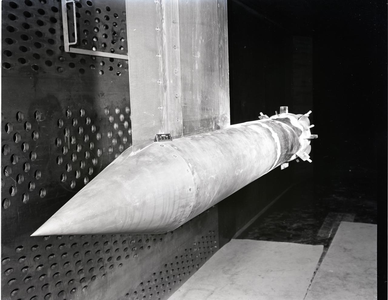
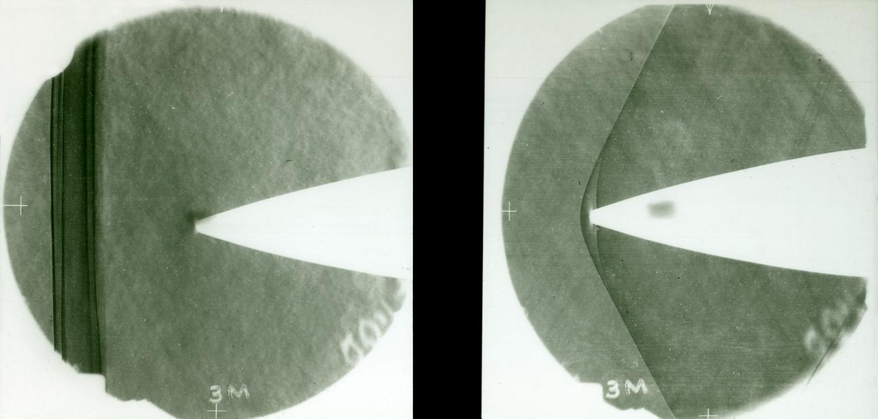
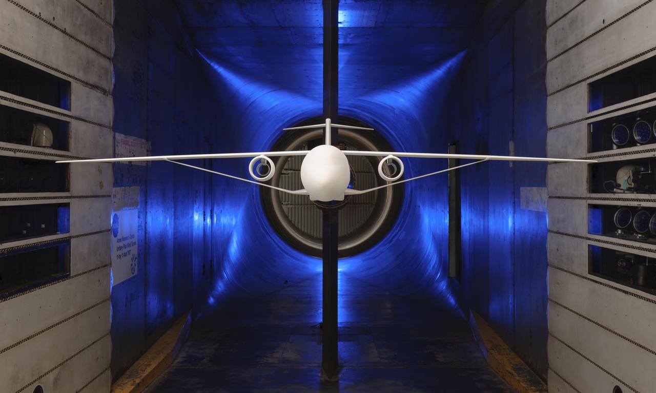
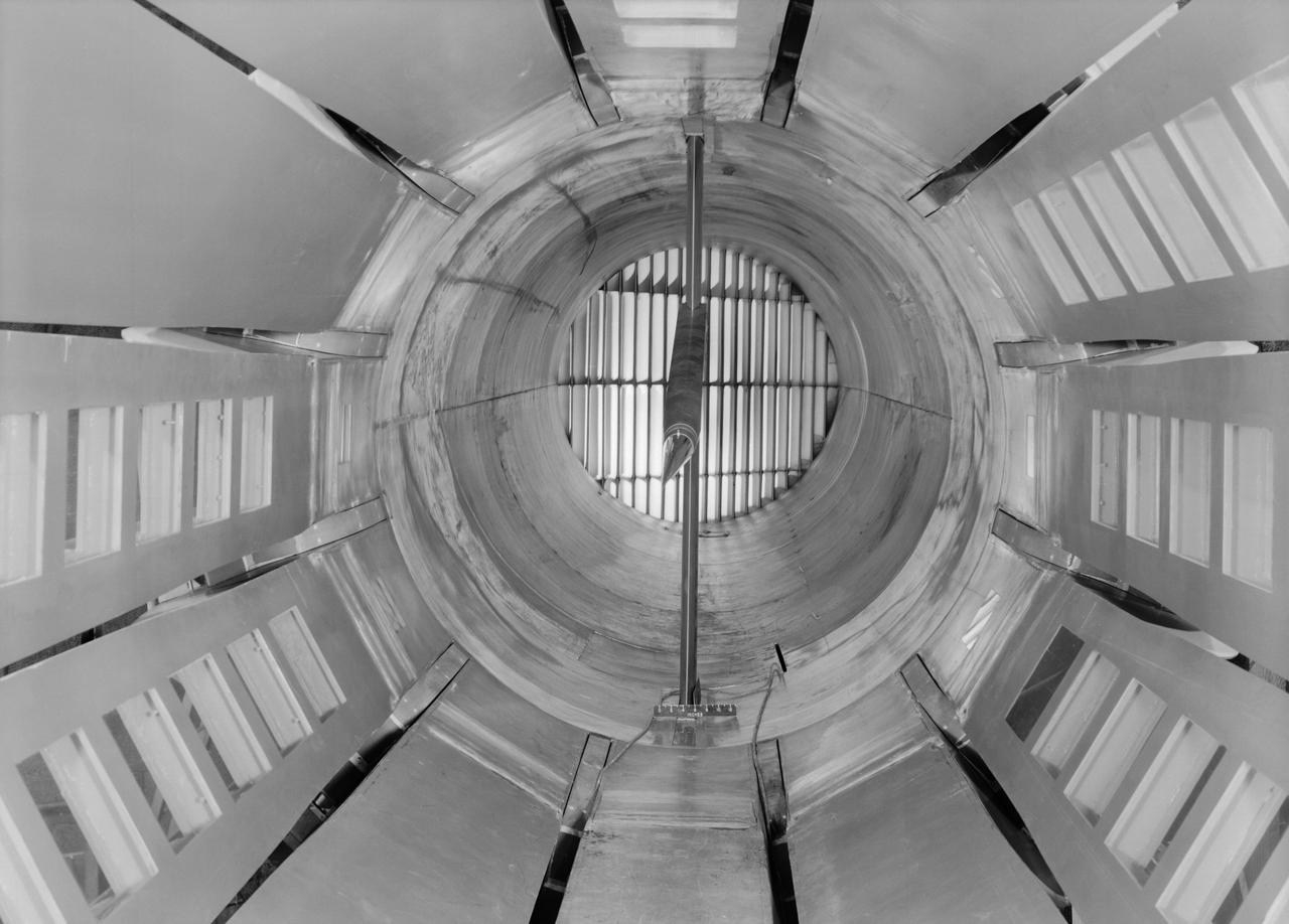
Dragging Its Foot
Dragging Its Foot
SR-3 Advanced Turboprop (Propfan) in 8x6 foot Supersonic Wind Tunnel
SR-3 Advanced Turboprop (Propfan) in 8x6 foot Supersonic Wind Tu
SR-3 Advanced Turboprop (Propfan) in 8x6 foot Supersonic Wind Tunnel (SWT)
SR-3 Advanced Turboprop (Propfan) in 8x6 foot Supersonic Wind Tu
Instrumentation in 16 Foot Wind Tunnel manometer boards
Instrumentation in 16 Foot Wind Tunnel
APOLLO STABILITY TEST IN THE 8X6 FOOT WIND TUNNEL - MODEL IS SHOWN WITH MODULE TOWER AND CANARDS
APOLLO STABILITY TEST IN THE 8X6 FOOT WIND TUNNEL - MODEL IS SHO
Counter Rotating Propeller Model in the NASA Glenn 8x6-Foot Supersonic Wind Tunnel
Counter Rotating Propeller Model in the NASA Glenn 8x6-Foot Supe
S84-27024 (7 Feb 1984) --- This 70mm frame centers on a foot restraint that strayed from the Earth-orbiting Space Shuttle Challenger during the February 9, 1984 extravehicular activity (EVA) session of astronauts Bruce McCandless II and Robert Stewart.  As seen in JSC photograph frame number S84-27025, McCandless goes after the piece.  Not pictured is Vance D. Brand, crew commander, who moved the spacecraft nearer the object.
View of foot restraint strayed from Challenger
NASA Ames Research Center 14-foot Transonic Wind Tunnel
ARC-1977-AC77-0846-11
Looking South from inside the diffuser of the 40x80 foot wind tunnel at NACA's Ames Research Center.  Construction began in late 1941, the mammoth construction task sorely taxing the resources of the new center. Two and a half years later, in dune 1944, the 40 x 80-foot full-scale tunnel went into operation.
Construction of the 40x80 Foot Wind Tunnel at Ames.
STS051-98-021 (16 Sept. 1993) --- In the Space Shuttle Discovery's aft cargo bay, astronaut Carl E. Walz gets his turn on the Portable Foot Restraint (PFR). Astronauts Walz, waving to his crew mates inside Discovery's cabin, and James H. Newman each put in some time evaluating the PFR, one of the pieces of gear to be used on the Hubble Space Telescope (HST) STS-61 servicing mission (scheduled later this year) and other Shuttle missions.
Astronaut Carl Walz test portable foot restraint in aft cargo bay
Motor and propeller blades in 40x80ft wind tunnel. Six 40-foot-diameter fans, each powered by a 6000-horsepower electric motor maintained airflow at 230 mph or less (these are still tornado velocities).
ARC-1969-AAL-5993. Six, 40-Foot-Diameter Fans in the Ames 40x80 Foot Wind Tunnel.
Avrocar in the shop of the 40x80 foot wind tunnel with the 4 prop tilt wing model in the back ground.
Avrocar in the shop of the 40x80 foot wind tunnel.
Publicity Shot of close up of Nacell, Drive Nacel and cooling vent in nose for wind tunnel in NACA Ames 40x80 foot Wind Tunnel.
Nacelles and props in 40x80 foot wind tunnel at Ames.
Clark Y Airfoil. 3/4 front view of 8x48 foot Clark Y Airfoil mounted (inverted) in the 40x80 foot wind tunnel at NACA's Ames Research Center.
A Clark Y Airfoil, mounted in the 40x80 foot wind tunnel.
(03/12/1976) 1/50 scale model of the 80x120 foot wind tunnel model (NFAC) in the test section of the 40x80 foot wind tunnel. Model mounted on a rotating ground board designed for this test, viewed from the west, oriented for North wind.
A76-0634. 1/50 Scale Model Of The 80X120 Foot Wind Tunnel Model (Nfac) In The Test Section Of The 40X80 Foot Wind Tunnel.
51I-102-048 (4-5 Sept 1985) --- A 35mm frame showing astronaut William F. Fisher standing on the edge of Discovery's cargo bay (in foot restraint) during the second day of a two-day effort to capture, repair and re-release the Syncom IV-3 communications satellite.  Astronaut James D. van Hoften, standing on the Discovery's RMS arm, exposed the frame.
Astronaut William Fisher anchored to foot restraint on Discovery
(Test 460) deHavilland Augmentor Wing 40x80 Foot Wind Tunnel.
deHavilland Augmentor Wing 40x80 Foot Wind Tunnel Test 460
Gliding parachute test in 40x80 foot Wind Tunnel, mounted on main strut flying horizontally.
Steerable Parachute for Apollo Vehicle in Ames 40x80 foot Wind Tunnel.
3/4 front view of Lockheed Rigid Rotor model in Ames 40x80 foot wind Tunnel.
Lockheed Rigid Rotor Model in Ames 40x80 Foot Wind Tunnel.
3/4 front view from below of Delta wing Model with Nose Inlet in Ames 40x80 foot wind tunnel.
Delta Wing Test Model in Ames 40x80 Foot Wind Tunnel.
3/4 front view from below of the Ryan FR-1 airplane mounted in the NACA Ames 40x80 foot wind tunnel. Production configuration.
Ryan FR-1 in NACA Ames 40x80 foot Wind Tunnel.
Investigation of High Lift and Stall Control on 45 deg. 3/4 front view Sweptback Cambered and Twisted Wing, in Ames 40x80 foot Wind Tunnel.
A-15209. High Lift and Stall Control in Ames 40x80 Foot Wind Tunnel.
A chambered and twisted wing-body. Arrow wing hypersonic model tested in the 6x6 foot wind tunnel at the NASA Ames Research Center.
Arrow Wing Model in the 6x6 Foot Wind Tunnel at NASA Ames.
3/4 front view of Fixed Wing SST - Lockheed SST on Ground Plane with leading edge flaps deflected in Ames 40x80 foot Wind Tunnel.
Fixed Wing Supersonic Transport in Ames 40x80 Foot Wind Tunnel.
Front lower view of Gates Learjet in Ames 40x80 foot wind tunnel at high angel of attack.  Test was part of a deep stall study.
Lear Jet test in Ames 40x80 Foot Wind Tunnel.
3/4 rear view of the Ryan FR-1 airplane mounted in the NACA Ames 40x80 foot wind tunnel from below. Production configuration.
Ryan FR-1 in 40x80 foot Wind Tunnel from below.
 17-foot test section in contraction cone of 300-MPH 7 x 10-Foot Tunnel (7 x 10-Foot test section in background).
300-MPH 7 x 10-Foot Tunnel
ISS011-E-13101 (16 Sept. 2005) --- Astronaut John L. Phillips, Expedition 11 NASA space station science officer and flight engineer, balances on the footplate of a special track attached to the Human Research Facility (HRF) rack in the Destiny laboratory on the International Space Station to perform Foot/Ground Reaction Forces During Spaceflight (FOOT) / Electromyography (EMG) calibration operations. Phillips is wearing the Lower Extremity Monitoring Suit (LEMS), the cycling tights outfitted with 20 sensors, which measures forces on joints and muscle activity.
Phillips during FOOT experiment
16 Foot Wind Tunnel personnel at work
16 Foot Wind Tunnel Personnel
 Drawing of the 8-Foot Transonic Pressure Tunnel.
8-Foot Transonic Pressure Tunnel
Concrete frame enclosing the fan drive bents of the 40x80 foot wind tunnel at ames.  Once installed, six 40-foot-diameter fans, each powered by a 6000-horsepower electric motor maintained airflow at 230 mph or less (these are still tornado velocities).
Construction of the Fan Drive Enclosure of the 40x80 Foot Wind Tunnel at Ames.
3/4 front view in Ames 40x80 foot Wind Tunnel investigation of the Lockheed T-33 modified for area-suction leading-edge and trailing edge flaps.
Northrop N-69 Missile in the Ames 40x80 foot Wind Tunnel.
Deep Stall Model in Ames 40x80 foot Wind Tunnel. 3/4 front view from below of swept wing jet transport with T-Tail and Aft Engins, with Art Morris.
Deep Stall Model in Ames 40x80 foot Wind Tunnel.
3/4 rear view from below of swept wing jet transport with T-Tail and Aft Engins, with Art Morris. Deep Stall Model in Ames 40x80 foot Wind Tunnel.
Deep Stall Model in Ames 40x80 foot Wind Tunnel.
Vertol-76 Descent Test. Tilt Wing airplane prop rig at 80 deg. Angle of attack, in the 40x80 foot wind tunnel at NASA's Ames Research Center.
Vertical Prop and Wing in the Ames 40x80 foot wind tunnel.
This engineer's concept drawing of the A-3 Test Stand shows the 300-foot-tall structure's open steel frame and large exhaust diffuser.
A-3 Test Stand
ISS011-E-09825 (29 June 2005) --- Astronaut John L. Phillips, Expedition 11 NASA Space Station science officer and flight engineer, enters data into a computer while participating in the Foot/Ground Reaction Forces During Spaceflight (FOOT) experiment in the Destiny laboratory of the International Space Station. Phillips wore the specially instrumented Lower Extremity Monitoring Suit (LEMS), cycling tights outfitted with sensors, during the experiment.
FOOT experiment (Foot/Ground Reaction Forces during Space Flight)
ISS011-E-09831 (29 June 2005) --- Astronaut John L. Phillips, Expedition 11 NASA Space Station science officer and flight engineer, works at the Canadarm2 controls while participating in the Foot/Ground Reaction Forces During Spaceflight (FOOT) experiment in the Destiny laboratory of the International Space Station. Phillips wore the specially instrumented Lower Extremity Monitoring Suit (LEMS), cycling tights outfitted with sensors, during the experiment.
FOOT experiment (Foot/Ground Reaction Forces during Space Flight)
ISS011-E-09822 (29 June 2005) --- Astronaut John L. Phillips, Expedition 11 NASA Space Station science officer and flight engineer, uses the Cycle Ergometer with Vibration Isolation System (CEVIS) while participating in the Foot/Ground Reaction Forces During Spaceflight (FOOT) experiment in the Destiny laboratory of the International Space Station. Phillips wore the specially instrumented Lower Extremity Monitoring Suit (LEMS), cycling tights outfitted with sensors, during the experiment.
FOOT experiment (Foot/Ground Reaction Forces during Space Flight)
Engineer and 12 foot Beacon showing NACA emblem on inflated  satelloon . For related information see, Spaceflight Revolution, NASA from Sputnik to Apollo, by James R. Hansen. NASA SP-4308, 1995. p. 173.
Twelve Foot Subsatellite
Engineer and 12 foot Beacon showing NACA emblem on inflated  satelloon . For related information see, Spaceflight Revolution, NASA from Sputnik to Apollo, by James R. Hansen. NASA SP-4308, 1995. p. 173.
Twelve Foot Subsatellite
Bell V/STOL X-14 airplane mounted at 90 degrees yaw in 40x80 foot wind tunnel.
Bell VSTOL X-14 Airplane in Ames 40x80 foot Wind Tunnel.
(Oct. 27 1976) Controllable Twist Rotor, 40x80 Foot Wind Tunnel at Ames Research Center, model With John Bolt.
Controllable Twist Rotor, 40x80 Foot Wind Tunnel at Ames Research Center.
3/4 front view of Lockheed AH-56A (Cheyenne) Helicopter in Ames 40x80 Foot Wind Tunnel
Lockheed AH-56A (Cheyenne) Helicopter in Ames 40x80 Foot Wind Tunnel
Publicity Photos of Bell Computing Machines at 19 Foot Pressure Tunnel Mrs. Doris Rudd Porter Baron photographed in the photos.
Publicity Photos of Bell Computing Machines at 19 Foot Pressure Tunnel
Publicity Photos of Bell Computing Machines at 19 Foot Pressure Tunnel Mrs. Doris Rudd Porter Baron photographed in the photos.
Publicity Photos of Bell Computing Machines at 19 Foot Pressure Tunnel
Publicity Photos of Bell Computing Machines at 19 Foot Pressure Tunnel Mrs. Doris Rudd Porter Baron photographed in the photos.
Publicity Photos of Bell Computing Machines at 19 Foot Pressure
Publicity Photos of Bell Computing Machines at 19 Foot Pressure Tunnel Mrs. Doris Rudd Porter Baron photographed in the photos.
Publicity Photos of Bell Computing Machines at 19 Foot Pressure Tunnel
Publicity Photos of Bell Computing Machines at 19 Foot Pressure Tunnel Mrs. Doris Rudd Porter Baron photographed in the photos.
Publicity Photos of Bell Computing Machines at 19 Foot Pressure Tunnel
Publicity Photos of Bell Computing Machines at 19 Foot Pressure Tunnel Mrs. Doris Rudd Porter Baron photographed in the photos.
Publicity Photos of Bell Computing Machines at 19 Foot Pressure Tunnel
Installation Photos, 3/4 front view from below. F-111B in Ames 40x80 Foot Wind Tunnel.  The General Dynamics/Grumman F-111B was a long-range carrier-based interceptor aircraft that was planned to be a follow-on to the F-4 Phantom II. The F-111B was developed in the 1960s by General Dynamics in conjunction with Grumman for the United States Navy (USN) as part of the joint Tactical Fighter Experimental (TFX) with the United States Air Force (USAF) to produce a common fighter for the services that could perform a variety of missions. It incorporated innovations such as variable-geometry wings, afterburning turbofan engines, and a long-range radar and missile weapons system.
F-111B in Ames 40x80 Foot Wind Tunnel.
Space Shuttle SSV Orbiter Model A100 0.36 Scale In 40x80 Foot Wind Tunnel. 3/4 lower rear view.
Space Shuttle SSV Orbiter Model In 40x80 Foot Wind Tunnel.
Looking West at three test section bents in place for the Ames 40 x 80 foot wind tunnel.  Concrete model scale support visible in the middle.
Construction of the Ring leading to the Test Section of the Ames 40x80 Foot Wind Tunnel.
Front View of -45 deg. Forward swept wing with inboard split flaps deflected 60 deg. In NACA Ames 40x80 foot Wind Tunnel.
Swept wing with inboard split flaps in Ames 40x80 foot Wind Tunnel.
F-14A fighter model lifted from the shop floor of the 40 x 80 foot wind tunnel.  3/4 scale
Grumman F-14A Airplane In Ames 40X80 Foot Wind Tunnel.
This image shows how NASA three-legged Phoenix Mars Lander is able to get a better look at its footing and the physical characteristics of the underlying soil on the surface of the Red Planet.
How Phoenix Gets a Look at its Footing
Saturn Model in 19 Foot Tunnel
Saturn Model in 19 Foot Tunnel at NASA Langley
3/4 front view of model without nacelles on regular struts. Generalized Subsonic Jet Transport model with leading edge and trailing edge blowing BLC in the 40x80 foot wind tunnel at NASA Ames.
Generalized Subsonic Jet Transport in 40x80 Foot Wind Tunnel at NASA Ames.
(11/12/1971) 3/4 rear view of swept 75% scale augmentor wing quest model being installed into the test section of the Ames 40x80 foot wind tunnel, overhead doors open.
Swept Augmentor Wing Model Installed in the Ames 40X80 Foot Wind Tunnel.
3/4 lower rear view of Controllable Twist Rotor (CTR) test of 4 blade helicopter model. Pictures with Ben Mandwyler Andy Lemnios, in 40x80 foot wind tunnel. Small flaps on rotor blades.
Controllable Twist Rotor in 40x80 Foot Wind Tunnel at Ames.
3/4 front view, a=0. de Havilland Augmenter Wing Model, High Lift System in Ames 40x80 Foot Wind Tunnel. Cecil McDonald and Al Wheelband in picture.
Augmenter Wing High Lift System in Ames 40x80 Foot Wind Tunnel.
Supersonic transport model test in 40x80 foot wind tunnel, 3/4 overhead view of model in shop floor.  04/06/1961 R 975 T
Supersonic Transport Model in the shop of the Ames 40x80 Foot Wind Tunnel.
Looking south at the construction of the test section of the 40 x 80 foot wind tunnel.  4 parts of a test section bent seen in the  foreground. Airship rising in the background.
Construction of the Ring Section of the 40x80 Foot Wind Tunnel at NACA Ames.
First airplane tested in the ames 40 x 80 foot wind tunnel. Douglas XSB2D-1 (Destroyer)  hanging from overhead crane above the test section.
Mounting Douglas XSB2D-1 Airplane In 40x80 Foot Wind Tunnel.
Prop Damage in the 8 foot TT (Transfer Tunnel)
APOLLO CONFIGURATION OF SATURN MODEL IN THE 8X6-FOOT SUPERSONIC WIND TUNNEL
APOLLO CONFIGURATION OF SATURN MODEL IN THE 8X6-FOOT SUPERSONIC
APOLLO CONFIGURATION OF SATURN MODEL IN THE 8X6-FOOT SUPERSONIC WIND TUNNEL
APOLLO CONFIGURATION OF SATURN MODEL IN THE 8X6-FOOT SUPERSONIC
APOLLO CONFIGURATION OF SATURN MODEL IN THE 8X6-FOOT SUPERSONIC WIND TUNNEL
APOLLO CONFIGURATION OF SATURN MODEL IN THE 8X6-FOOT SUPERSONIC
APOLLO CONFIGURATION OF SATURN MODEL IN THE 8X6-FOOT SUPERSONIC WIND TUNNEL
APOLLO CONFIGURATION OF SATURN MODEL IN THE 8X6-FOOT SUPERSONIC
Avrocar Annular Jet VTOL Airplane in Ames 40x80 foot Wind Tunnel.
Overhead View of Avrocar Annular Jet VTOL Airplane in Ames 40x80 foot Wind Tunnel.
3/4 lower front view of Controllable Twist Rotor (CTR) test of 4 blade helicopter model.  Pictures with Ben Mandwyler Andy Lemnios, John McCloud (wheel chair), in 40x80 foot wind tunnel.  Small flaps on rotor blades.
Controllable Twist Rotor in 40x80 Foot Wind Tunnel at Ames.
Test No. 175  Kaman K-16 in 40x80 Foot Wind Tunnel at Ames Research Center. Pictured with two Kaman employees.  3/4 Front view of Airplane.  Kaman K-16B was an experimental tilt wing aircraft, it used the fuselage of a JRF-5 and was powered by two General Electric YT58-GE-2A engines.
Kaman K-16 in 40x80 Foot Wind Tunnel at Ames Research Center.
Test No. 175  Kaman K-16 in 40x80 Foot Wind Tunnel at Ames Research Center.  Kaman K-16B was an experimental tilt wing aircraft, it used the fuselage of a JRF-5 and was powered by two General Electric YT58-GE-2A engines.
Kaman K-16 in 40x80 Foot Wind Tunnel at Ames Research Center.
Test No. 175  Kaman K-16 being lowered into the 40x80 foot wind tunnel at NASA's Ames Research Center, viewed from the front. Kaman K-16B was an experimental tilt wing aircraft, it used the fuselage of a JRF-5 and was powered by two General Electric YT58-GE-2A engines.
Kaman K-16 in 40x80 Foot Wind Tunnel at Ames Research Center.
Aerial view looking North West of the nearly completed 40 x 80 foot wind tunnel.  Drive and test section exposed. The facility covered 8 acres, and the air circuit was just over 1/2 mile long (2700 feet).
Aerial View of the Nearly Completed 40x80 Foot Wind Tunnel at Ames
The 8- by 6-Foot Supersonic Wind Tunnel at the National Advisory Committee for Aeronautics (NACA) Lewis Flight Propulsion Laboratory was the nation’s largest supersonic facility when it began operation in April 1949. The emergence of new propulsion technologies such as turbojets, ramjets, and rockets during World War II forced the NACA and the aircraft industry to develop new research tools. In late 1945 the NACA began design work for new large supersonic wind tunnels at its three laboratories. The result was the 4- by 4-Foot Supersonic Wind Tunnel at Langley Memorial Aeronautical Laboratory, 6- by 6-foot supersonic wind tunnel at Ames Aeronautical Laboratory, and the largest facility, the 8- by 6-Foot Supersonic Wind Tunnel in Cleveland. The two former tunnels were to study aerodynamics, while the 8- by 6 facility was designed for supersonic propulsion.    The 8- by 6-Foot Supersonic Wind Tunnel was used to study propulsion systems, including inlets and exit nozzles, combustion fuel injectors, flame holders, exit nozzles, and controls on ramjet and turbojet engines. Flexible sidewalls alter the tunnel’s nozzle shape to vary the Mach number during operation. A seven-stage axial compressor, driven by three electric motors that yield a total of 87,000 horsepower, generates air speeds from Mach 0.36 to 2.0. A section of the tunnel is seen being erected in this photograph.
Construction of the 8- by 6-Foot Supersonic Wind Tunnel
 8-Foot Transonic Pressure Tunnel (TPT): Sample of Schlieren results Left - Mach     1.03 Right - Mach     1.20.
8-Foot Transonic Pressure Tunnel (TPT)
William J. O Sullivan at desk with folded subsatellite, 30 inch subsatellite, 12 foot subsatellite, and corner reflector.
Twelve foot Subsatellite and Corner Reflector, Wm. O'Sullivan
Truss-braced wind model installed in the Ames 11x11 Foot Wind Tunnel for testing as part of the Subsonic Ultra Green Aircraft Research Project (SUGAR)
ACD16-0013-013
Parametric Inlet Model in 10x10 Wind Tunnel
GRC-2004-C-00378
ISS012-E-14518 (10 Jan. 2006) --- Astronaut William S. (Bill) McArthur, Expedition 12 commander and NASA space station science officer, talks to Mission Control Center while holding the Total Force Foot Ground Interface (TF-FGI) during Foot/Ground Reaction Forces During Spaceflight (FOOT) experiment set-up operations in the Destiny laboratory of the International Space Station. The Foot Ground Interface Flight Calibration Unit (FGI-GCU) is visible at right.
McArthur performs FOOT setup operations during Expedition 12
4 propeller Tilt Wing. Pictured with Tommy Wills wind tunnel mechanic in the 40x80 foot wind tunnel.
Tilt-Wing/Propeller Model With Blowing Flaps Tested in the 40x80 foot Wind Tunnel at NASA Ames.
Long Range Laser Velocimeter in 40x80x120 Foot Wind Tunnel at NASA Ames. For use in NFAC.
ISS012-E-20043 (9 March 2006) --- Astronaut William S. (Bill) McArthur, Expedition 12 commander and NASA space station science officer, sets up the electromyography (EMG) calibration cord assembly for a data collection session of the Foot/Ground Reaction Forces During Spaceflight (FOOT) experiment in the Destiny laboratory of the International Space Station. McArthur was attired in the specially instrumented Lower Extremity Monitoring Suit (LEMS), cycling tights outfitted with sensors for the experiment.
McArthur conducts the last FOOT session for Expedition 12
JSC2004-E-35439 (11 August 2004) --- Astronaut Leroy Chiao, Expedition 10 commander and NASA ISS science officer, participates in Foot/Ground Reaction Forces During Spaceflight (FOOT) Integrated nominal operations during Human Research Facility (HRF) training in the International Space Station (ISS) Destiny laboratory mockup/trainer at Johnson Space Center’s Space Vehicle Mockup Facility.
Expedition 10 Preflight Training, Foot Nominal Operations
Truss-Braced Wind Model installed in the Ames 11x11 Foot Wind Tunnel for testing. The Truss-Braced model is part of the Subsonic Ultra Green Aircraft Research Project (SUGAR)
ACD16-0013-026
Truss-braced wind model installed in the Ames 11x11 Foot Wind Tunnel for testing as part of the Subsonic Ultra Green Aircraft Research Project (SUGAR) Shown here with test engineer Greg Gatlin, Langley Research Center.
ACD16-0013-015
Test of Lockheed YC-130 Turbo-Propeller Installation in Ames 40x80 Foot Wind Tunnel. 3/4 front view from below.
Tests of Lockheed YC-130 Turbo-Propeller Installation in Ames 40x80 Foot Wind Tunnel.
Lockheed XH-51 Experimental Rigid Rotors, no hinges, in Ames 40x80 foot wind tunnel. John McCloud (left sitting) Jack Rabbot (Right).
Lockheed XH-51 Helicopter with Experimental Rigid Rotors in the 40x80 Foot Wind Tunnel at NASA Ames.
3/4 front view of Douglas F5D Skylancer modified to "ogee" platform inlet plug installed in Ames 40x80 foot wind tunnel.
F-5D Airplane modified to "ogee" platform inlet plug installed in Ames 40x80 foot wind tunnel.
Installation of 1/3 scale model of space shuttle orbiter into the test section of the Ames 40x80 foot wind tunnel with overhead doors open.
Installation of 1/3 scale model of Space Shuttle Orbiter into 40x80 Foot Wind Tunnel.
iss072e397228 (Dec. 19, 2024) --- The Brahmaputra River, in eastern India at the foot of the Himalayas near China, is pictured from the International Space Station as it orbited 261 miles above.
The Brahmaputra River in eastern India at the foot of the Himalayas
 Interior view of the slotted throat test section installed in the 8-Foot High Speed Tunnel (HST) in 1950.  The slotted region is about 160 inches in length. In this photograph, the sting-type model support is seen straight on. In a NASA report, the test section is described as follows:  The test section of the Langley 8-foot transonic tunnel is dodecagonal in cross section and has a cross-sectional area of about 43 square feet. Longitudinal slots are located between each of the 12 wall panels to allow continuous operation through the transonic speed range. The slots contain about 11 percent of the total periphery of the test section. Six of the twelve panels have windows in them to allow for schlieren observations. The entire test section is enclosed in a hemispherical shaped chamber.  John Becker noted that the tunnel s  final achievement was the development and use in routine operations of the first transonic slotted throat. The investigations of wing-body shapes in this tunnel led to Whitcomb s discovery of the transonic area rule.  James Hansen described the origins of the the slotted throat as follows:  In 1946 Langley physicist Ray H. Wright conceived a way to do transonic research effectively in a wind tunnel by placing slots in the throat of the test section. The concept for what became known as the slotted-throat or slotted-wall tunnel came to Wright not as a solution to the chronic transonic problem, but as a way to get rid of wall interference (i.e., the mutual effect of two or more meeting waves or vibrations of any kind caused by solid boundaries) at subsonic speeds.  For most of the year before Wright came up with this idea, he had been trying to develop a theoretical understanding of wall interference in the 8-Foot HST, which was then being repowered for Mach 1 capability.  When Wright presented these ideas to John Stack, the response was enthusiastic but neither Wright nor Stack thought of slotted-throats as a solution to the transonic problem, only the wall interference problem.  It was an accidental discovery which showed that slotted throats might solve the transonic problem. Most engineers were skeptical but Stack persisted. Initially, plans were to modify the 16-Foot tunnel but in the spring of 1948, Stack announced that the 8-Foot HST would also be modified. As Hansen notes:  The 8-Foot HST began regular transonic operations for research purposes on 6 October 1950.  The concept was a success and led to plans for a new wind tunnel which would be known as the 8-Foot Transonic Pressure Tunnel. -- Published in U.S., National Advisory Committee for Aeronautics,  Characteristics of Nine Research Wind Tunnels of the Langley Aeronautical Laboratory,  1957, pp. 17, 22  James R. Hansen, Engineer in Charge, NASA SP-4305, p. 454 and Chapter 11,  The Slotted Tunnel and the Area Rule.
8-Foot High Speed Tunnel (HST)
ISS012-E-14529 (10 Jan. 2006) --- Astronaut William S. (Bill) McArthur, Expedition 12 commander and NASA space station science officer, performs Foot/Ground Reaction Forces During Spaceflight (FOOT) experiment set-up operations in the Destiny laboratory of the International Space Station. Foot Ground Interface Flight Calibration Unit (FGI-FCU) is visible upper right and the Lower Extremity Monitoring Suit (LEMS) is visible in the foreground.
McArthur performs FOOT setup operations during Expedition 12
3/4 front view from below, showing Pods and Fan Rotating. March A. Zeiger standing in front. Tandem Dual Ducted Fan V/STOL Model in Ames 40x80 foot Wind Tunnel
Tandem Dual Ducted Fan V/STOL Model in Ames 40x80 foot Wind Tunnel.
3/4 front view of M-1-L inflatable recovery able lifting body model in Ames 40x80 foot wind tunnel. Mechanic, Ray Schmorance included in picture.
M-1-L Inflatable Recovery able Lifting Body Model in Ames 40x80 foot Wind Tunnel.
Schlieren photographs of the model in 4 x 4 Foot supersonic pressure tunnel
Foreword, front view of McDonnell Model XV-1 Convertiplane in the Ames 40x80 Foot Wind Tunnel.  The McDonnell XV-1 was an experimental compound gyroplane developed for a joint research program between the United States Air Force and the United States Army to explore technologies to develop an aircraft that could take off and land like a helicopter but fly at faster airspeeds, similar to a conventional airplane. The XV-1 would reach a speed of 200 mph (322 km/h), faster than any previous rotorcraft, but the program was terminated due to the tip-jet noise and complexity of the technology which gave only a modest gain in performance.
McDonnell Model XV-1 Convertiplane in the Ames 40x80 Foot Wind Tunnel.