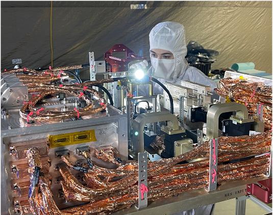
An engineer inspects the radio frequency (RF) panel of NASA's Europa Clipper in a cleanroom at the Johns Hopkins Applied Physics Laboratory in Laurel, Maryland. The RF panel hosts all the RF subsystem electronics and an intricate routing network of switches, filters, and waveguides, which carry the RF signal to and from eight antennas distributed around the spacecraft. With an internal global ocean under a thick layer of ice, Jupiter's moon Europa may have the potential to harbor existing life. Europa Clipper will swoop around Jupiter in an elliptical orbit, dipping close to the moon on each flyby to collect data. Understanding Europa's habitability will help scientists better understand how life developed on Earth and the potential for finding life beyond our planet. Europa Clipper is set to launch in 2024. https://photojournal.jpl.nasa.gov/catalog/PIA24898
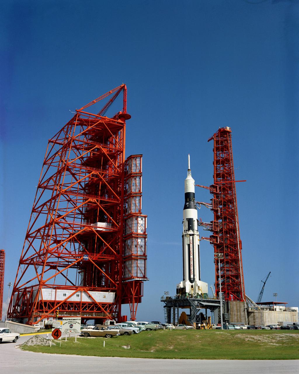
View of a Saturn I on the launch pad for a Radio Frequency Interference Test, to be conducted at LC-37A. Cape Kennedy Missile Test Center
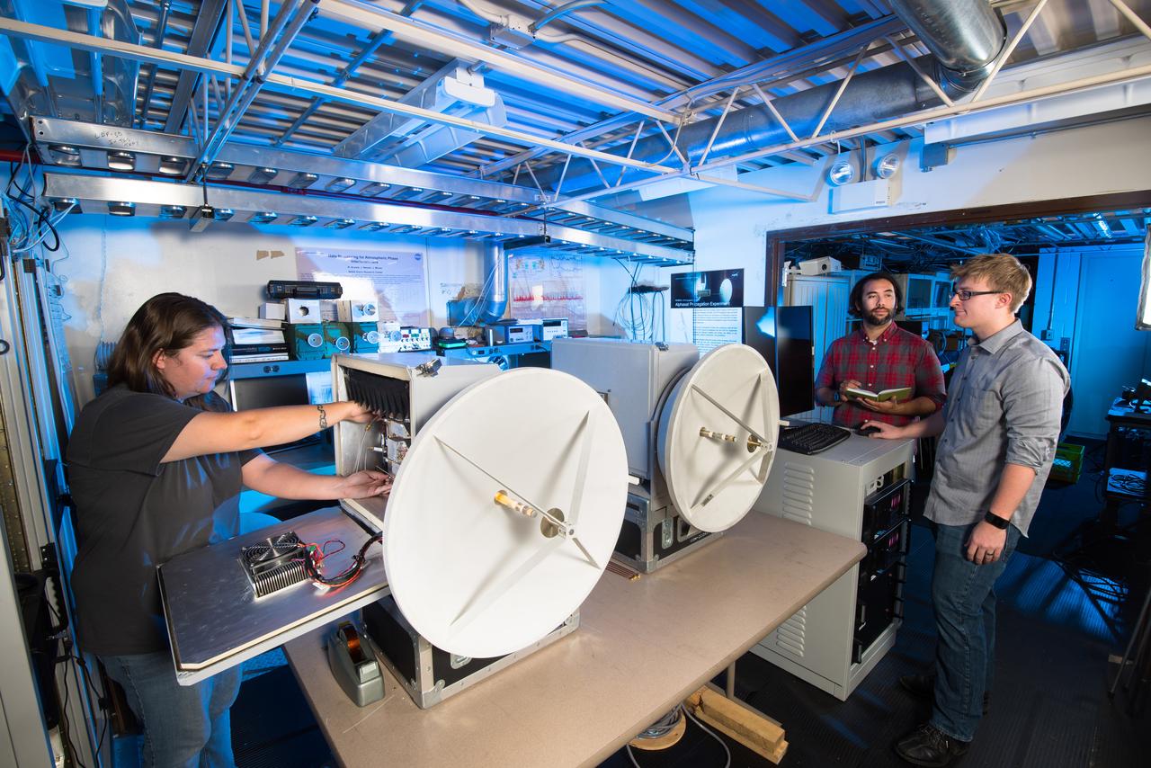
NASA Glenn researchers Jacki Houts, James Nessel and Michael Zemba perform a final inspection of the W/V-Band Terrestrial Link Experiment (WTLE) before it was transported to Albuquerque, New Mexico for testing. The experiment hardware includes a transmitter, which has been placed on the crest of the Sandia Mountains and a receiver (shown) placed at a research facility of the University of New Mexico. The wireless link spans 23km and will be used to study the effects of the atmosphere on high data-rate wireless communication links at 72 and 84 GHz. The goal of the experiment is to study these frequency bands for satellite communications.
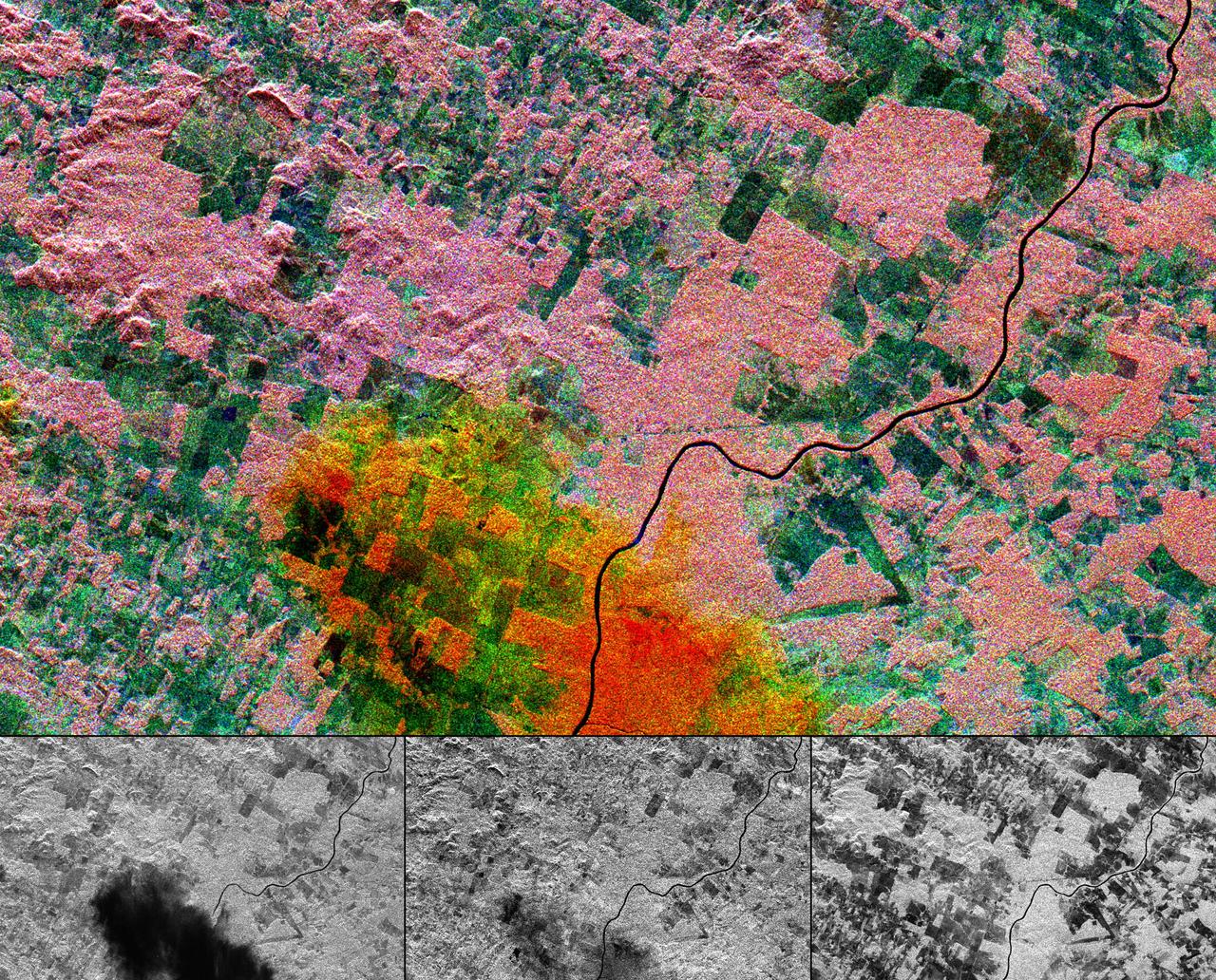
This multi-frequency space radar image of a tropical rainforest in western Brazil shows rapidly changing land use patterns and it also demonstrates the capability of the different radar frequencies to detect and penetrate heavy rainstorms.
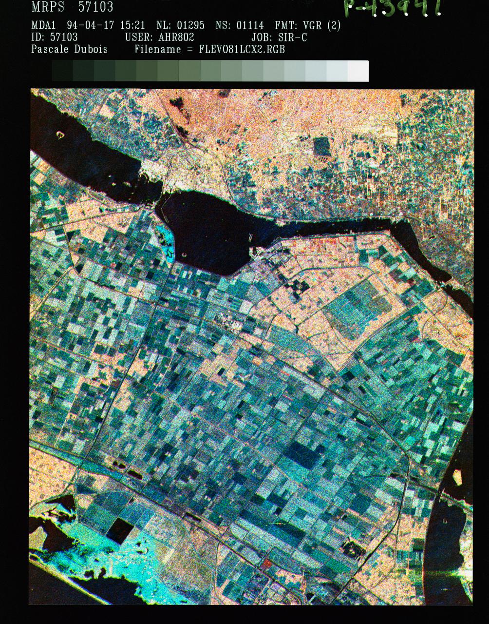
STS059-S-086 (18 April 1994) --- This is a three-frequency false-color image of Flevoland, the Netherlands, centered at 52.4 degrees north latitude, and 5.4 degrees east longitude. This image was acquired by the Spaceborne Imaging Radar-C and X-Band Synthetic Aperture Radar (SIR-C/X-SAR) aboard the Space Shuttle Endeavour on April 14, 1994. It was produced by combining data from the X-Band, C-Band and L-Band radar's. The area shown is approximately 25 by 28 kilometers (15 1/2 by 17 1/2 miles). Flevoland, which fills the lower two-thirds of the image, is a very flat area that is made up of reclaimed land that is used for agriculture and forestry. At the top of the image, across the canal from Flevoland, is an older forest shown in red; the city of Harderwijk is shown in white on the shore of the canal. At this time of the year, the agricultural fields are bare soil, and they show up in this images in blue. The changes in the brightness of the blue areas are equal to the changes in roughness. The dark blue areas are water and the small dots in the canal are boats. This SIR-C/X-SAR supersite is being used for both calibration and agricultural studies. Several soil and crop ground-truth studies will be conducted during the Shuttle flight. In addition, about 10 calibration devices and 10 corner reflectors have been deployed to calibrate and monitor the radar signal. One of these transponders can be seen as a bright star in the lower right quadrant of the image. This false-color image was made using L-Band total power in the red channel, C-Band total power in the green channel, and X-Band VV polarization in the blue channel. SIR-C/X-SAR is part of NASA's Mission to Planet Earth (MTPE). SIR-C/X-SAR radars illuminate Earth with microwaves allowing detailed observations at any time, regardless of weather or sunlight conditions. SIR-C/X-SAR uses three microwave wavelengths: L-Band (24 cm), C-Band (6 cm), and X-Band (3 cm). The multi-frequency data will be used by the international scientific community to better understand the global environment and how it is changing. The SIR-C/X-SAR data, complemented by aircraft and ground studies, will give scientists clearer insights into those environmental changes which are caused by nature and those changes which are induced by human activity. SIR-C was developed by NASA's Jet Propulsion Laboratory (JPL). X-SAR was developed by the Dornire and Alenia Spazio Companies for the German Space Agency, Deutsche Agentur fuer Raumfahrtangelegenheiten (DARA), and the Italian Space Agency, Agenzia Spaziale Italiana (ASI). JPL Photo ID: P-43941
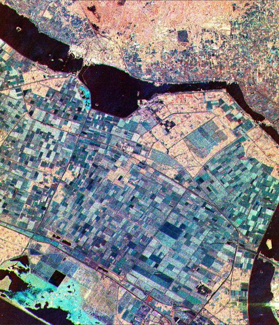
This is a three-frequency false color image of Flevoland, The Netherlands, centered at 52.4 degrees north latitude, 5.4 degrees east longitude.
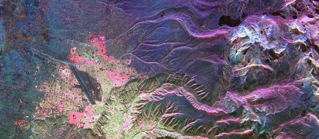
This is an image of the Bolivian capital city of La Paz that was created using three radar frequencies.
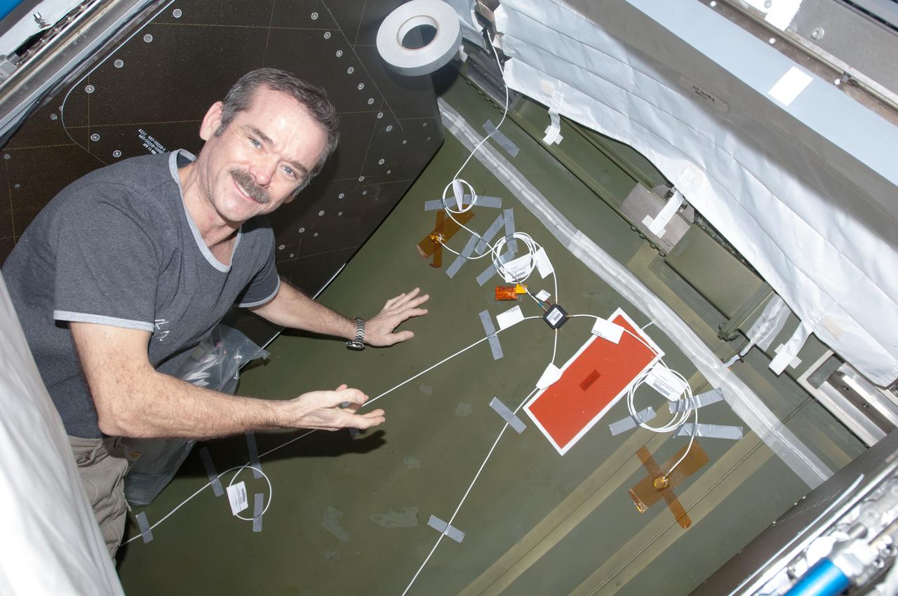
View of Canadian Space Agency (CSA) Chris Hadfield,Expedition 34 Flight Engineer (FE),installing Ultra-Sonic Background Noise Tests (UBNT) sensors behind rack in the U.S. Laboratory using the International Space Station (ISS) as Testbed for Analog Research (ISTAR) procedures. These sensors detect high frequency noise levels generated by ISS hardware and equipment operating within the U.S. Laboratory. Photo was taken during Expedition 34.
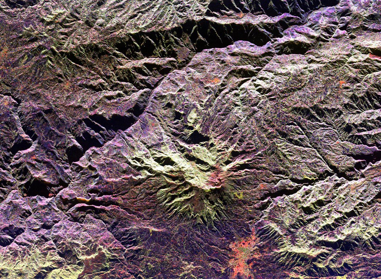
This radar image of the area surrounding the Galeras volcano in southern Colombia shows the ability of a multi-frequency radar to map volcanic structures that can be dangerous to study on the ground.
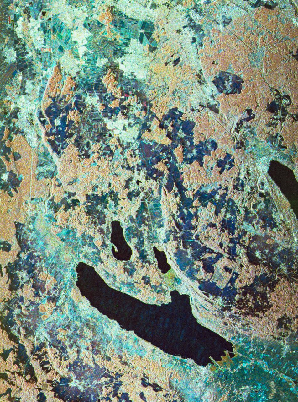
STS059-S-080 (18 April 1994) --- This is a false-color three frequency image of the Oberpfaffenhofen supersite, an area just south-west of Munich in southern Germany. The colors show the different conditions that the three radars (X-Band, C-Band and L-Band) can see on the ground. The image covers a 27 by 36 kilometer area. The center of the site is 48.09 degrees north and 11.29 degrees east. The image was acquired by the Spaceborne Imaging Radar-C and X-Band Synthetic Aperture Radar (SIR-C/X-SAR) onboard the Space Shuttle Endeavour on April 11, 1994. The dark area on the left is Lake Ammersee. The two smaller lakes are the Woerthsee and the Pilsensee. On the bottom is the tip of the Starnbergersee. The city of Munich is located just beyond the right of the image. The Oberpfaffenhofen supersite is the major test site for SIR-C/X-SAR calibration and scientific investigations concerning agriculture, forestry, hydrology and geology. This color composite image is a three frequency overlay. L-Band total power was assigned red, the C-Band total power is shown in green and the X-Band VV polarization appears blue. The colors on the image stress the differences between the L-Band, C-Band, X-Band images. If the three radar antennas were getting an equal response from objects on the ground, this image would appear in black and white. However, in this image, the blue areas corresponds to area for which the X-Band backscatter is relatively higher than the backscatter at L and C-Bands. This behavior is characteristic of grasslands, clear cuts and shorter vegetation. Similarly, the forested areas have a reddish tint (L-Band). The green areas seen near both the Ammersee and the Pilsensee lakes indicate marshy areas. The agricultural fields in the upper right hand corner appear mostly in blue and green (X-Band and C-Band). The white areas are mostly urban areas, while the smooth surfaces of the lakes appear very dark. SIR-C/X-SAR is part of NASA's Mission to Planet Earth (MTPE). SIR-C/X-SAR radars illuminate Earth with microwaves allowing detailed observations at any time, regardless of weather or sunlight conditions. SIR-C/X-SAR uses three microwave wavelengths: L-Band (24 cm), C-Band (6 cm), and X-Band (3 cm). The multi-frequency data will be used by the international scientific community to better understand the global environment and how it is changing. The SIR-C/X-SAR data, complemented by aircraft and ground studies, will give scientists clearer insights into those environmental changes which are caused by nature and those changes which are induced by human activity. SIR-C was developed by NASA's Jet Propulsion Laboratory (JPL). X-SAR was developed by the Dornire and Alenia Spazio Companies for the German Space Agency, Deutsche Agentur fuer Raumfahrtangelegenheiten (DARA), and the Italian Space Agency, Agenzia Spaziale Italiana (ASI). JPL Photo ID: P-43930
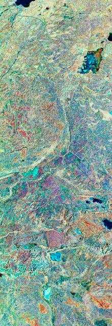
STS059-S-079 (18 April 1994) --- This is a false-color, three frequency image of Prince Albert, Canada, centered at 53.91 north latitude and 104.69 west longitude. It was produced using data from the X-Band, C-Band and L-Band radars that comprise the Spaceborne Imaging Radar-C and X-Band Synthetic Aperture Radar (SIR-C/X-SAR). SIR-C/X-SAR acquired this image on the 20th orbit of the Space Shuttle Endeavour. The area is located 40 kilometers north and 30 kilometers east of the town of Prince Albert in the Saskatchewan province of Canada. The image covers the area east of the Candle Lake, between gravel surface Highways 120 and 106 and west of 106. The area in the middle of the image covers the entire Nipawin (Narrow Hills) provincial park. The look angle of the radar is 30 degrees and the size of the image is approximately 20 by 50 kilometers. The red, green, and blue colors represent L-Band total power, C-Band total power, and XVV respectively. The changes in the intensity of each color are related to various surface conditions such as frozen or thawed forest, fire, deforestation and areas of regrowth. Most of the dark blue areas in the image are the ice covered lakes. The dark area on the top right corner of the image is the White Gull Lake north of the intersection of Highway 120 and 913. The right middle part of the image shows Lake Ispuchaw and Lower Fishing Lake. The deforested areas are shown by light blue in the image. Since most of the logging practice at the Prince Albert area is around the major highways, the deforested areas can be easily detected as small geometrically shaped dark regions along the roads. At the time these data were taken, a major part of the forest was either frozen or undergoing the spring thaw. In such conditions, due to low volume of water in the vegetation, a deeper layer of the canopy is imaged by the radar, revealing valuable information about the type of trees, the amount of vegetation biomass and the condition of the surface. As the frequency increases, the penetration depth in the canopy decreases. Over forest canopies, the X-Band radar contains information about the top of the canopy. Whereas, C-Band and L-Band radar returns show contributions from the crown and trunk areas respectively. The bright areas in the image are dense mixed aspen and old jackpine forests where the return from all three bands is high. The reddish area corresponds to more sparse old jack pine (12 to 17 meters in height and 60 to 75 years old) where the L-Band signal penetrates deeper in the canopy and dominates C-Band and X-Band returns. Comparison of the image with the forest cover map of the area indicates that the three band radar can be used to classify various stands. SIR-C/X-SAR is part of NASA's Mission to Planet Earth (MTPE). SIR-C/X-SAR radars illuminate Earth with microwaves allowing detailed observations at any time, regardless of weather or sunlight conditions. SIR-C/X-SAR uses three microwave wavelengths: L-Band (24 cm), C-Band (6 cm), and X-Band (3 cm). The multi-frequency data will be used by the international scientific community to better understand the global environment and how it is changing. The SIR-C/X-SAR data, complemented by aircraft and ground studies, will give scientists clearer insights into those environmental changes which are caused by nature and those changes which are induced by human activity. SIR-C was developed by NASA's Jet Propulsion Laboratory (JPL). X-SAR was developed by the Dornire and Alenia Spazio Companies for the German Space Agency, Deutsche Agentur fuer Raumfahrtangelegenheiten (DARA), and the Italian Space Agency, Agenzia Spaziale Italiana (ASI). JPL Photo ID: P-43929
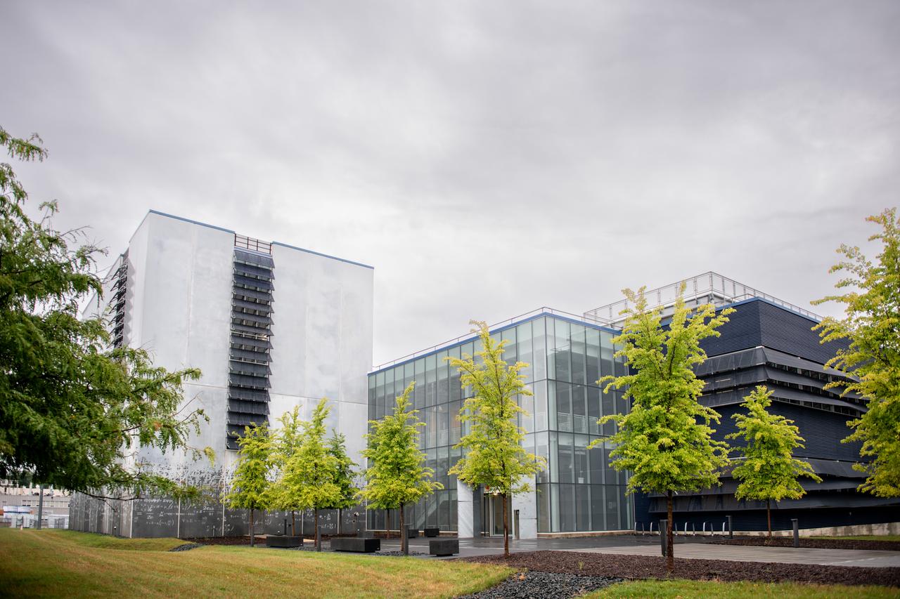
NASA’s Glenn Research Center opened the doors to a brand-new mission-focused facility that will support the agency’s Artemis and Advanced Air Mobility missions. On Aug. 30, NASA management and local officials cut the ribbon to the Aerospace Communications Facility (ACF), a new building designed for advanced radio frequency (RF) and optical communication technology research and development. Photo Credit: (NASA/Sara Lowthian-Hanna)
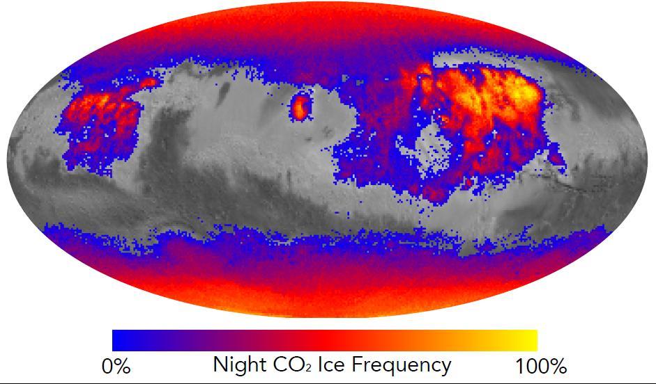
This map shows the frequency of carbon dioxide frost's presence at sunrise on Mars, as a percentage of days year-round. Carbon dioxide ice more often covers the ground at night in some mid-latitude regions than in polar regions, where it is generally absent for much of summer and fall. Color coding is based on data from the Mars Climate Sounder instrument on NASA's Mars Reconnaissance Orbiter. A color-key bar below the map shows how colors correspond to frequencies. Yellow indicates high frequencies, identifying areas where carbon dioxide ice is present on the ground at night during most of the year. Blue identifies areas where it is rarely present; red is intermediate. Areas without color coding are regions where carbon dioxide frost is not detected at any time of year. The areas with highest frequency of overnight carbon dioxide frost correspond to regions with surfaces of loose dust, which do not retain heat well, compared to rockier areas. Those areas also have some of the highest mid-afternoon temperatures on the planet. The dust surface heats up and cools off rapidly. http://photojournal.jpl.nasa.gov/catalog/PIA20758
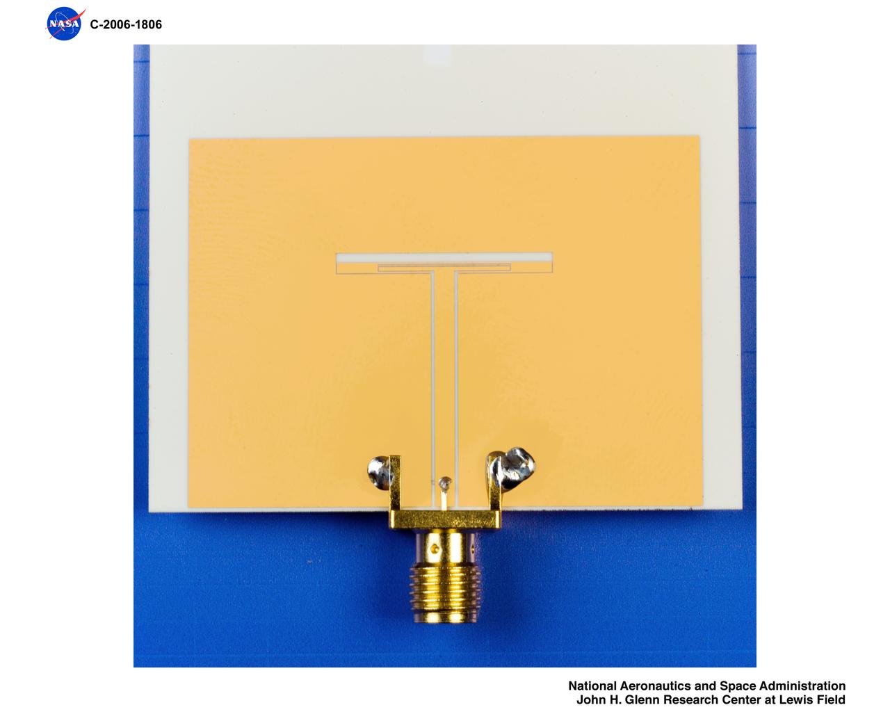
Dual Frequency Slot Antenna
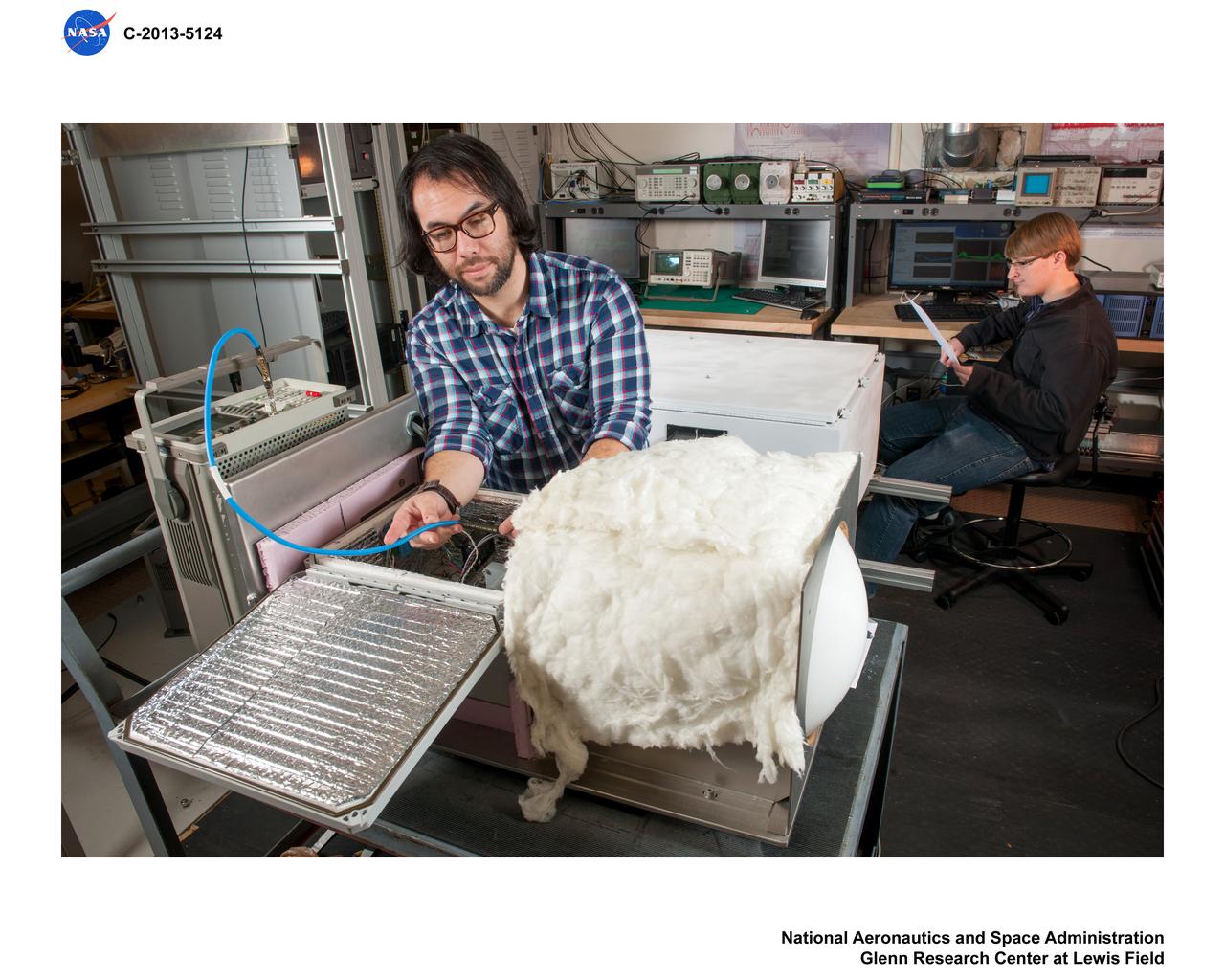
RF, Radio Frequency, Propagation Studies
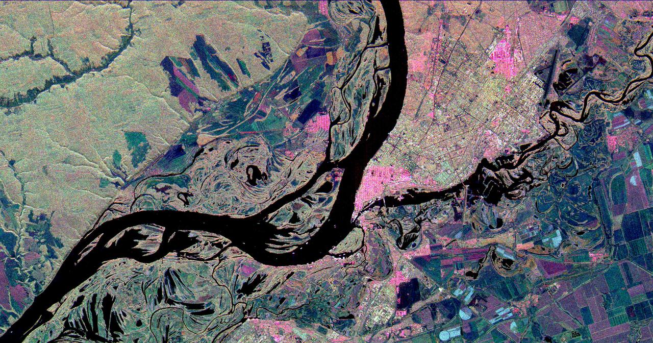
This three-frequency space radar image shows the city of Samara, Russia in pink and light green right of center. Samara is at the junction of the Volga and Samara Rivers approximately 800 kilometers 500 miles southeast of Moscow.

Tones represents sound waves that traveled through the early universe, and were later heard by ESA Planck space telescope. The primordial sound waves have been translated into frequencies we can hear.
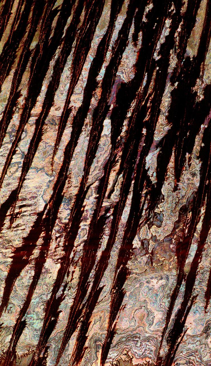
This three-frequency space radar image of west central Egypt shows detailed patterns of eroded sedimentary rock formations emerging through a vast sea of sand dunes.
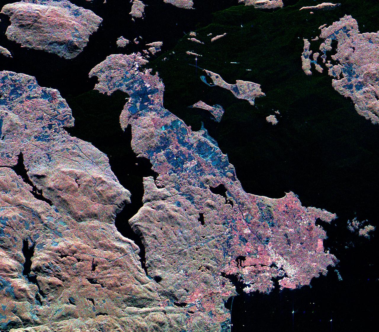
This three-frequency spaceborne radar image shows the southern end of Vancouver Island on the west coast of Canada. The white area in the lower right is the city of Victoria, the capital of the province of British Columbia.
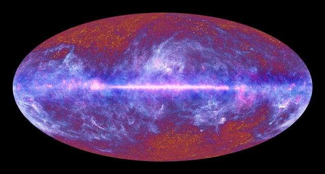
This image of the microwave sky was synthesized using data spanning the range of light frequencies detected by ESA Planck. A vast portion of the sky is dominated by the diffuse emission from gas and dust in our Milky Way galaxy.
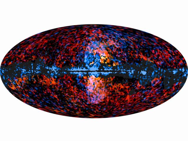
This all-sky image shows the distribution of the galactic haze seen by ESA Planck mission at microwave frequencies superimposed over the high-energy sky, as seen by NASA Fermi Gamma-ray Space Telescope.
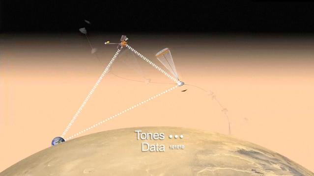
This frame from an artist animation depicts how NASA Curiosity rover will communicate with Earth during landing. As the rover descends to Mars, it will send out basic radio-frequency tones that go directly to Earth.
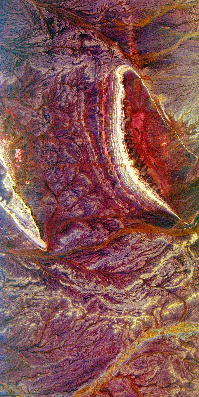
Bright, arc-shaped limestone hills and complex, branching drainage patterns dominate this three-frequency space radar image of a desert area in the north central plain of Oman.
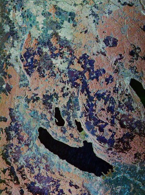
This is a false-color, three-frequency image of the Oberpfaffenhofen supersite, southwest of Munich in southern Germany, which shows the differences in what the three radar bands can see on the ground.

This three-frequency space radar image of south-central Egypt demonstrates the unique capability of imaging radar to penetrate thin sand cover in arid regions to reveal hidden details below the surface.
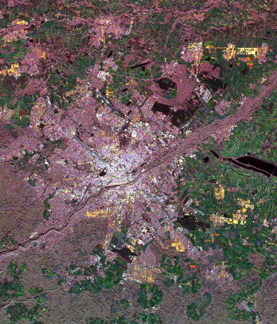
This spaceborne radar image of Munich, Germany illustrates the capability of a multi-frequency radar system to highlight different land use patterns in the area surrounding Bavaria largest city.
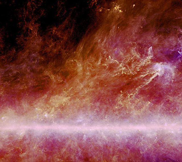
This three-color combination constructed from ESA Planck two highest frequency channels and an image obtained with the NASA Infrared Astronomical Satellite shows local dust structures within 500 light-years of the sun.
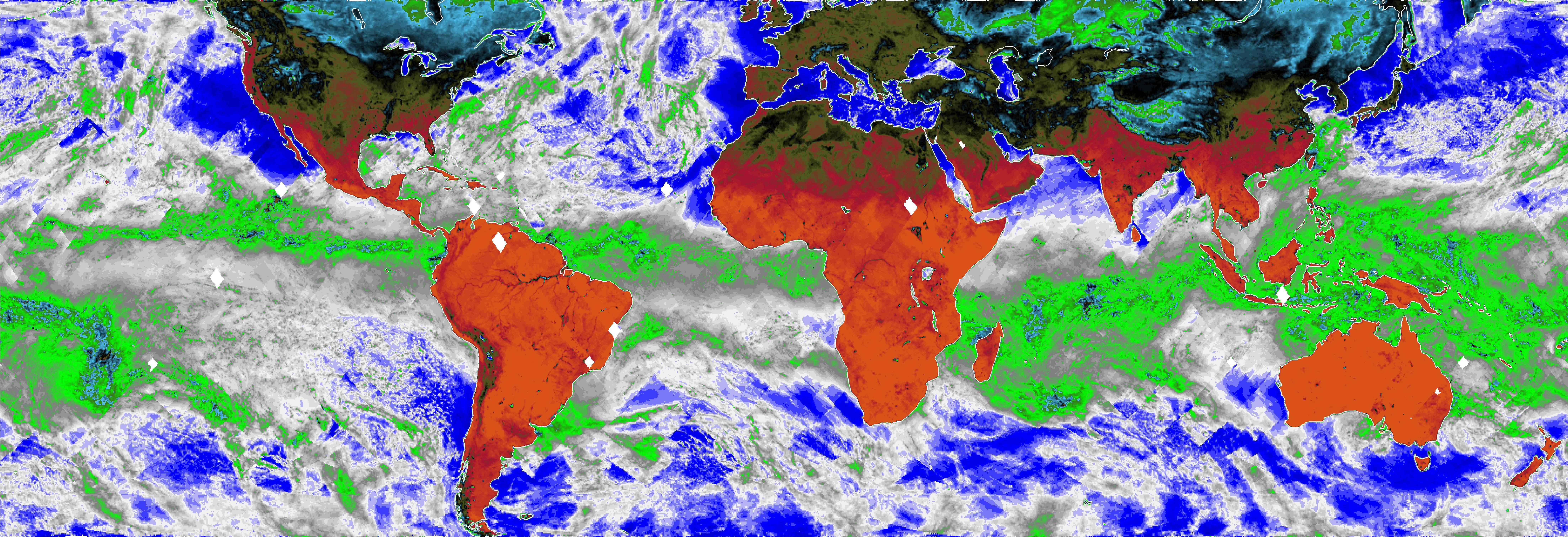
This map, made using the Compact Ocean Wind Vector Radiometer (COWVR) instrument's observations from Jan. 16 to 23, 2022, shows Earth's microwave emissions at a frequency of 34 gigahertz. This frequency provides information on the strength of winds at the ocean surface, the amount of water in clouds, and the amount of water vapor in the atmosphere. Green and white indicate higher water vapor and clouds, while dark blue over the ocean indicates drier air and clear sky. Typical weather patterns for January, such as tropical moisture and rain (the green band stretching across the center of the map), are visible. https://photojournal.jpl.nasa.gov/catalog/PIA24985
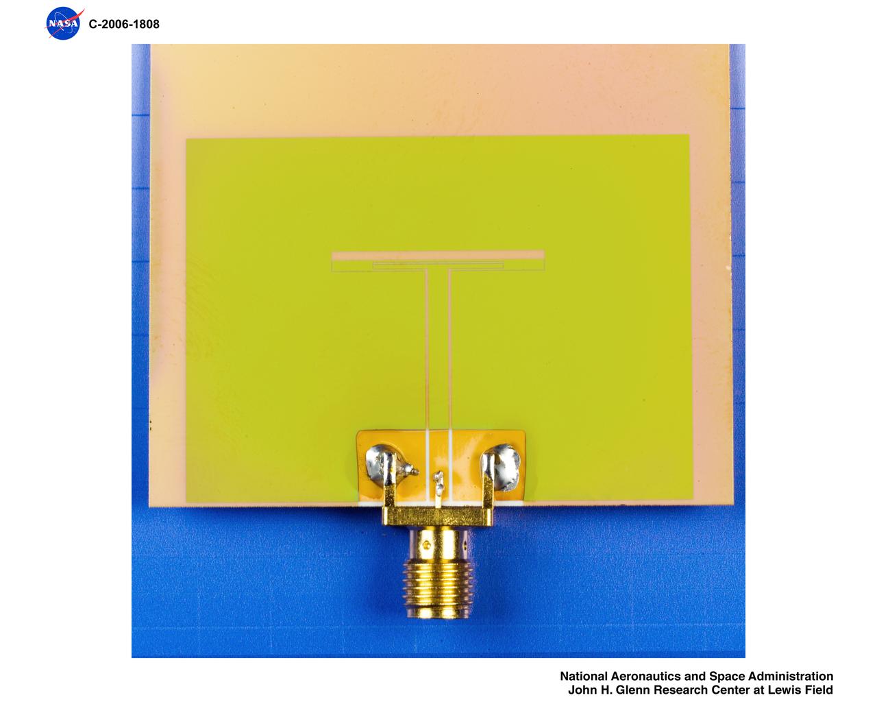
Dual Frequency Slot Antenna with SiC Thin Film Packaging Technology
CAPE CANAVERAL, Fla. – A telemetry antenna and tracker camera is attached to the roof of the Launch Control Center, or LCC, in Launch Complex 39 at NASA's Kennedy Space Center in Florida. This antenna and camera system is the first of three to be installed on the LCC roof for the Radio Frequency and Telemetry Station RFTS, which will be used to monitor radio frequency communications from a launch vehicle at Launch Pad 39A or B as well as provide radio frequency relay for a launch vehicle in the Vehicle Assembly Building. The RFTS replaces the shuttle-era communications and tracking labs at Kennedy. The modern RFTS checkout station is designed to primarily support NASA's Space Launch System, or SLS, and Orion spacecraft, but can support multi-user radio frequency tests as the space center transitions to support a variety of rockets and spacecraft. For more information on the modernization efforts at Kennedy, visit the Ground Systems Development and Operations, or GSDO, website at http://go.nasa.gov/groundsystems. Photo credit: NASA/Jim Grossmann
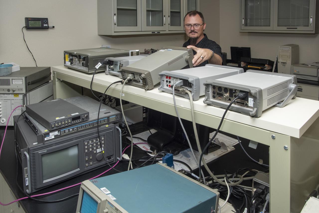
Paul Craig calibrates specialized high-level radio frequency equipment at NASA’s Armstrong Flight Research Center in California.
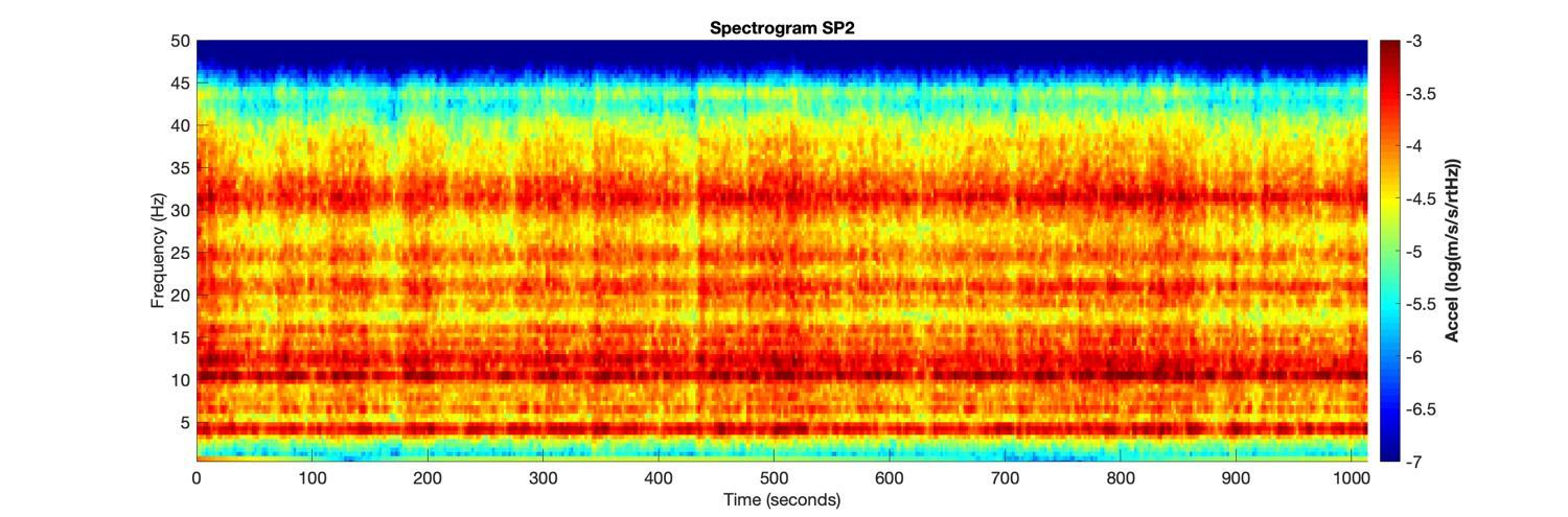
The spectrogram of vibrations (frequency spectrum over time) recorded by two of the three sensors of the short period seismometer on NASA's InSight lander on Mars. This spectrogram shows the first 1,000 seconds, roughly 20 minutes, of InSight's first seismic data from the Red Planet. The vibrations of the lander are due to the wind passing over the spacecraft, particularly the large solar arrays. https://photojournal.jpl.nasa.gov/catalog/PIA22925
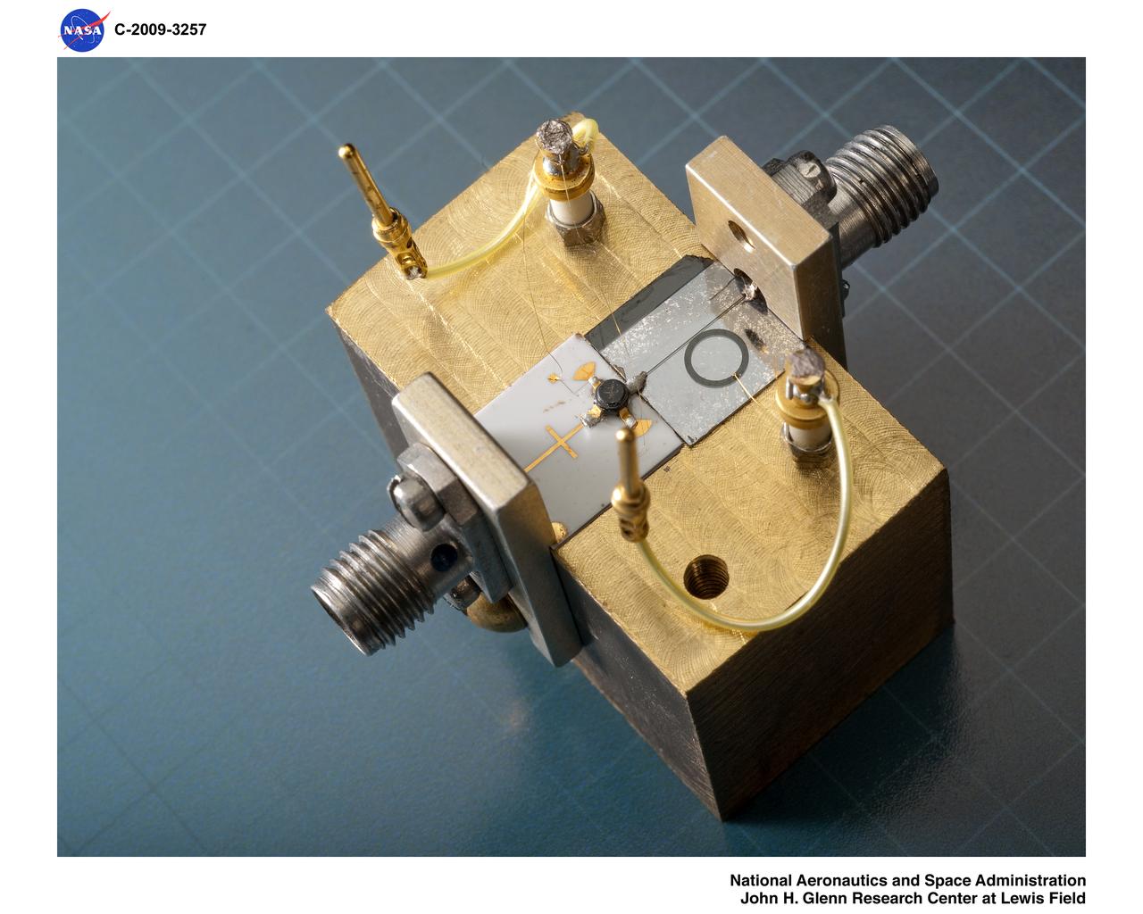
Photo will be included in the book "Ferroelectric Films at Microwave Frequencies" edited by Dr. P. Bao, Dr. TJ Jackson and Dr. PM Suherman
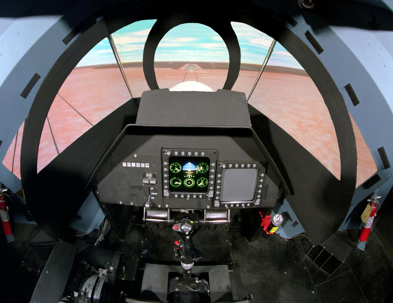
NASA Ames Vertical Motion Simulator (VMS): F-cab SIMFR (Simulation Frequency Response) Project; Pilots cockpit and out-the-window (OTW) view
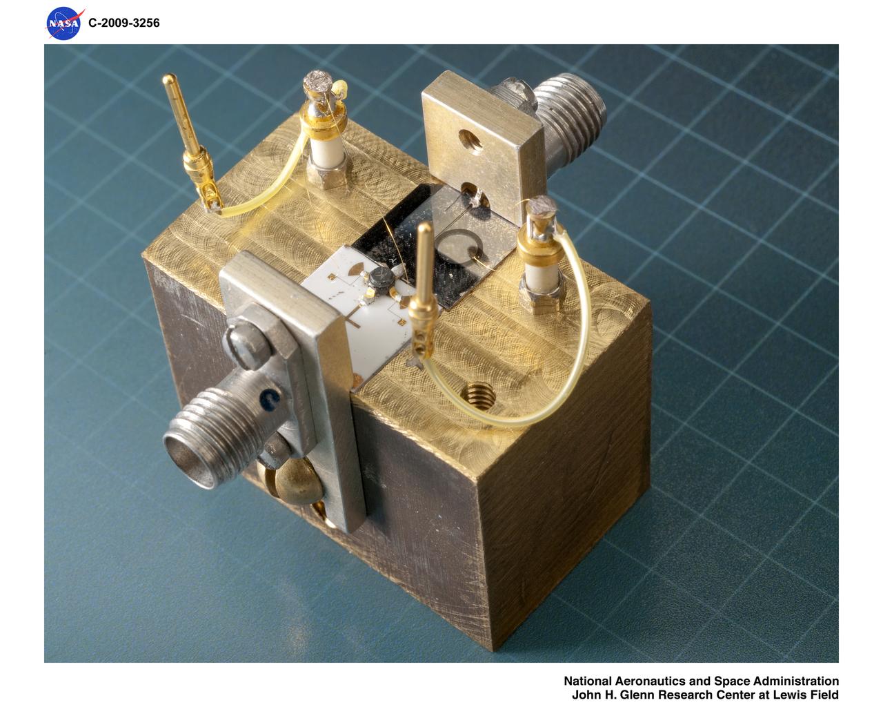
Photo will be included in the book "Ferroelectric Films at Microwave Frequencies" edited by Dr. P. Bao, Dr. TJ Jackson and Dr. PM Suherman
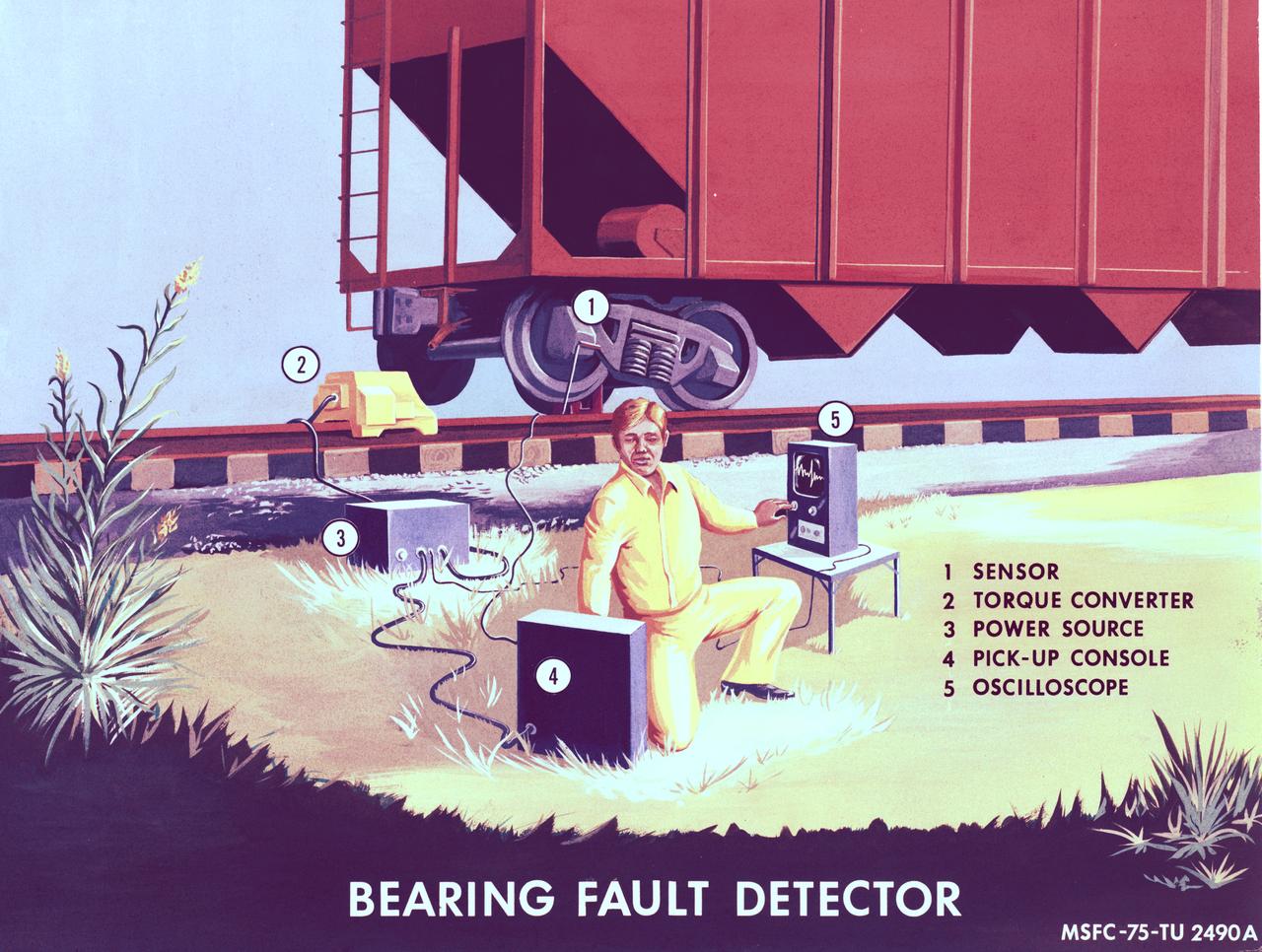
Technology derived by NASA for monitoring control gyros in the Skylab program is directly applicable to the problems of fault detection of railroad wheel bearings. Marhsall Space Flight Center's scientists have developed a detection concept based on the fact that bearing defects excite resonant frequency of rolling elements of the bearing as they impact the defect. By detecting resonant frequency and subsequently analyzing the character of this signal, bearing defects may be detected and identified as to source.
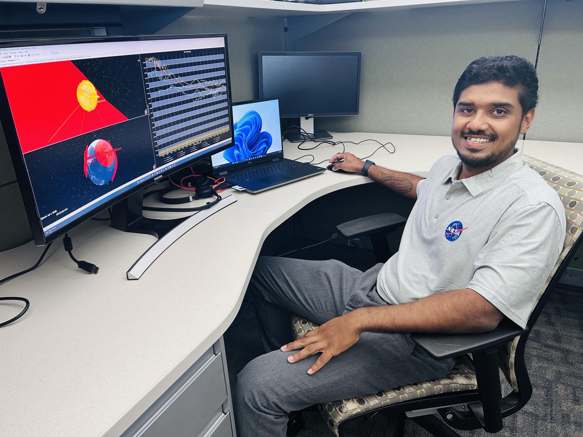
Rohit Goeptar, an electromagnetic/radio frequency analyst with NASA’s Launch Services Program at the agency’s Kennedy Space Center in Florida, reviews a radio frequency link budget analysis for NASA’s Nancy Grace Roman Space Telescope from his office. Goeptar is among the engineers and technicians sworn in as new NASA civil servants as part of NASA Administrator Jared Isaacman’s workforce directive to restore technical core competencies within the civil servants ranks.

Rohit Goeptar, an electromagnetic/radio frequency analyst with NASA’s Launch Services Program at the agency’s Kennedy Space Center in Florida, reviews a radio frequency link budget analysis for NASA’s Nancy Grace Roman Space Telescope with a colleague. Goeptar is among the engineers and technicians sworn in as new NASA civil servants as part of NASA Administrator Jared Isaacman’s workforce directive to restore technical core competencies within the civil servants ranks.
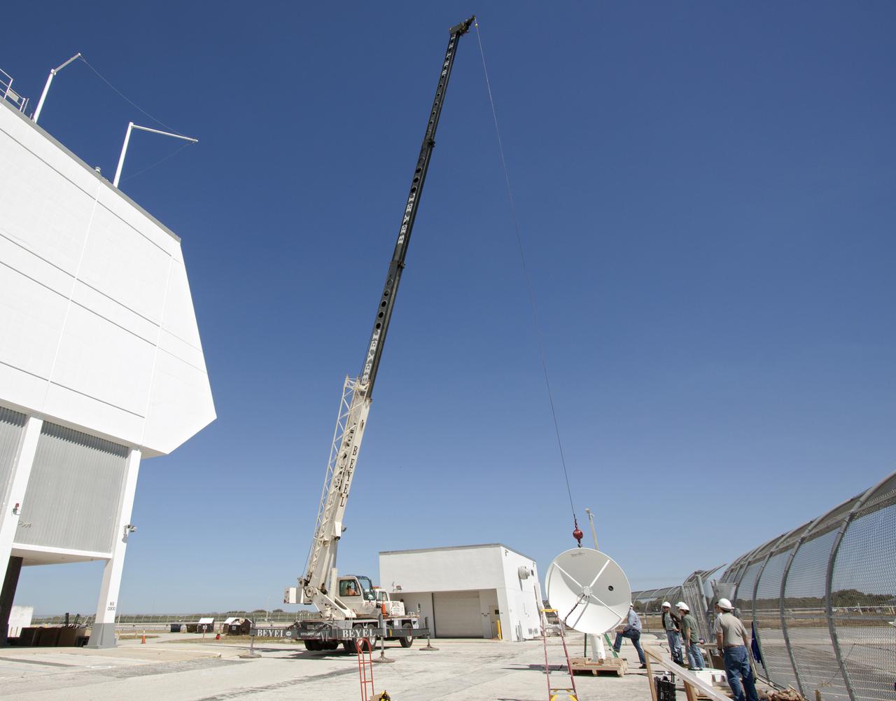
CAPE CANAVERAL, Fla. – Workers use a crane to install a new parabolic telemetry antenna and tracker camera to the roof of the Launch Control Center, or LCC, in Launch Complex 39 at NASA's Kennedy Space Center in Florida. This antenna and camera system is the first of three that will be installed on the LCC roof for the Radio Frequency and Telemetry Station RFTS, which will be used to monitor radio frequency communications from a launch vehicle at Launch Pad 39A or B as well as provide radio frequency relay for a launch vehicle in the Vehicle Assembly Building. The RFTS replaces the shuttle-era communications and tracking labs at Kennedy. The modern RFTS checkout station is designed to primarily support NASA's Space Launch System, or SLS, and Orion spacecraft, but can support multi-user radio frequency tests as the space center transitions to support a variety of rockets and spacecraft. For more information on the modernization efforts at Kennedy, visit the Ground Systems Development and Operations, or GSDO, website at http:__go.nasa.gov_groundsystems. Photo credit: NASA_Jim Grossmann
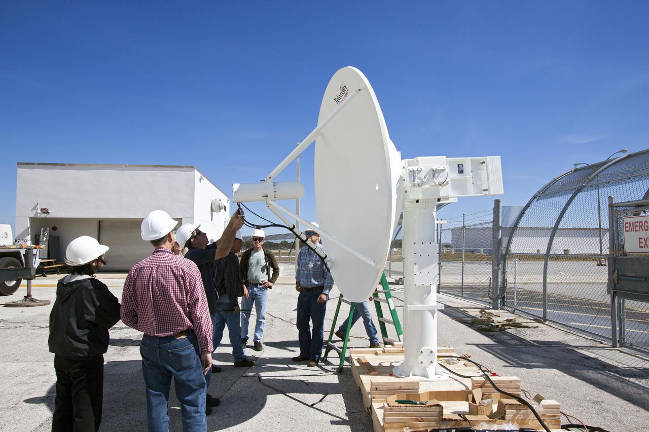
CAPE CANAVERAL, Fla. – Workers prepare to install a new parabolic telemetry antenna and tracker camera to the roof of the Launch Control Center, or LCC, in Launch Complex 39 at NASA's Kennedy Space Center in Florida. This antenna and camera system is the first of three that will be installed on the LCC roof for the Radio Frequency and Telemetry Station RFTS, which will be used to monitor radio frequency communications from a launch vehicle at Launch Pad 39A or B as well as provide radio frequency relay for a launch vehicle in the Vehicle Assembly Building. The RFTS replaces the shuttle-era communications and tracking labs at Kennedy. The modern RFTS checkout station is designed to primarily support NASA's Space Launch System, or SLS, and Orion spacecraft, but can support multi-user radio frequency tests as the space center transitions to support a variety of rockets and spacecraft. For more information on the modernization efforts at Kennedy, visit the Ground Systems Development and Operations, or GSDO, website at http:__go.nasa.gov_groundsystems. Photo credit: NASA_Jim Grossmann
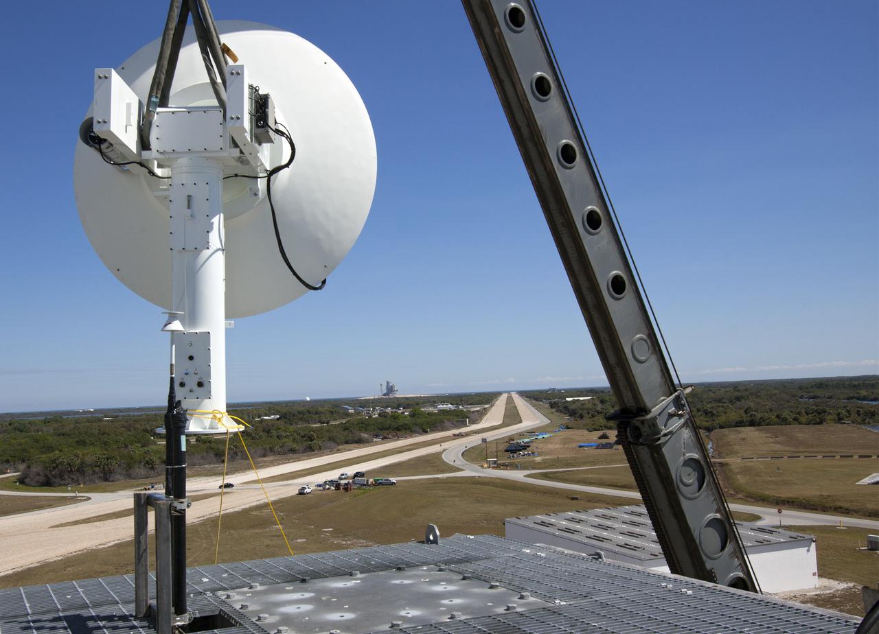
CAPE CANAVERAL, Fla. – With the help of a crane, a worker helps guide a parabolic telemetry antenna and tracker camera to the roof of the Launch Control Center, or LCC, in Launch Complex 39 at NASA's Kennedy Space Center in Florida. This antenna and camera system is the first of three that will be installed on the LCC roof for the Radio Frequency and Telemetry Station RFTS, which will be used to monitor radio frequency communications from a launch vehicle at Launch Pad 39A or B as well as provide radio frequency relay for a launch vehicle in the Vehicle Assembly Building. The RFTS replaces the shuttle-era communications and tracking labs at Kennedy. The modern RFTS checkout station is designed to primarily support NASA's Space Launch System, or SLS, and Orion spacecraft, but can support multi-user radio frequency tests as the space center transitions to support a variety of rockets and spacecraft. For more information on the modernization efforts at Kennedy, visit the Ground Systems Development and Operations, or GSDO, website at http://go.nasa.gov/groundsystems. Photo credit: NASA/Jim Grossmann
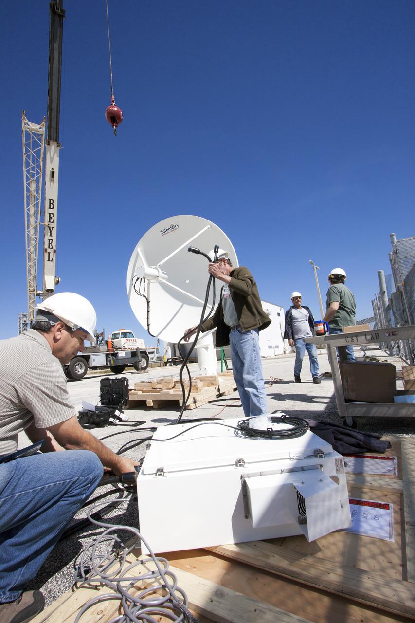
CAPE CANAVERAL, Fla. – Workers prepare to install a new parabolic telemetry antenna and tracker camera via crane to the roof of the Launch Control Center, or LCC, in Launch Complex 39 at NASA's Kennedy Space Center in Florida. This antenna and camera system is the first of three that will be installed on the LCC roof for the Radio Frequency and Telemetry Station RFTS, which will be used to monitor radio frequency communications from a launch vehicle at Launch Pad 39A or B as well as provide radio frequency relay for a launch vehicle in the Vehicle Assembly Building. The RFTS replaces the shuttle-era communications and tracking labs at Kennedy. The modern RFTS checkout station is designed to primarily support NASA's Space Launch System, or SLS, and Orion spacecraft, but can support multi-user radio frequency tests as the space center transitions to support a variety of rockets and spacecraft. For more information on the modernization efforts at Kennedy, visit the Ground Systems Development and Operations, or GSDO, website at http:__go.nasa.gov_groundsystems. Photo credit: NASA_Jim Grossmann
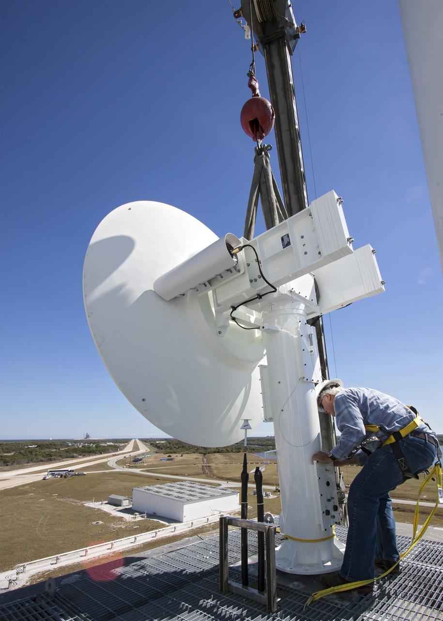
CAPE CANAVERAL, Fla. – A crane lifts a new parabolic telemetry antenna and tracker camera to the roof of the Launch Control Center, or LCC, in Launch Complex 39 at NASA's Kennedy Space Center in Florida. This antenna and camera system is the first of three that will be installed on the LCC roof for the Radio Frequency and Telemetry Station RFTS, which will be used to monitor radio frequency communications from a launch vehicle at Launch Pad 39A or B as well as provide radio frequency relay for a launch vehicle in the Vehicle Assembly Building. The RFTS replaces the shuttle-era communications and tracking labs at Kennedy. The modern RFTS checkout station is designed to primarily support NASA's Space Launch System, or SLS, and Orion spacecraft, but can support multi-user radio frequency tests as the space center transitions to support a variety of rockets and spacecraft. For more information on the modernization efforts at Kennedy, visit the Ground Systems Development and Operations, or GSDO, website at http:__go.nasa.gov_groundsystems. Photo credit: NASA_Jim Grossmann

CAPE CANAVERAL, Fla. – A crane lifts a new parabolic telemetry antenna and tracker camera to the roof of the Launch Control Center, or LCC, in Launch Complex 39 at NASA's Kennedy Space Center in Florida. This antenna and camera system is the first of three that will be installed on the LCC roof for the Radio Frequency and Telemetry Station RFTS, which will be used to monitor radio frequency communications from a launch vehicle at Launch Pad 39A or B as well as provide radio frequency relay for a launch vehicle in the Vehicle Assembly Building. The RFTS replaces the shuttle-era communications and tracking labs at Kennedy. The modern RFTS checkout station is designed to primarily support NASA's Space Launch System, or SLS, and Orion spacecraft, but can support multi-user radio frequency tests as the space center transitions to support a variety of rockets and spacecraft. For more information on the modernization efforts at Kennedy, visit the Ground Systems Development and Operations, or GSDO, website at http:__go.nasa.gov_groundsystems. Photo credit: NASA_Jim Grossmann
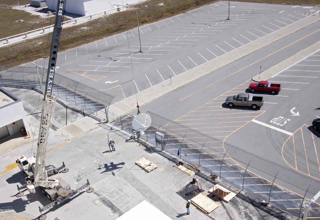
CAPE CANAVERAL, Fla. – Workers use a crane to install a new parabolic telemetry antenna and tracker camera to the roof of the Launch Control Center, or LCC, in Launch Complex 39 at NASA's Kennedy Space Center in Florida. This antenna and camera system is the first of three that will be installed on the LCC roof for the Radio Frequency and Telemetry Station RFTS, which will be used to monitor radio frequency communications from a launch vehicle at Launch Pad 39A or B as well as provide radio frequency relay for a launch vehicle in the Vehicle Assembly Building. The RFTS replaces the shuttle-era communications and tracking labs at Kennedy. The modern RFTS checkout station is designed to primarily support NASA's Space Launch System, or SLS, and Orion spacecraft, but can support multi-user radio frequency tests as the space center transitions to support a variety of rockets and spacecraft. For more information on the modernization efforts at Kennedy, visit the Ground Systems Development and Operations, or GSDO, website at http:__go.nasa.gov_groundsystems. Photo credit: NASA_Jim Grossmann
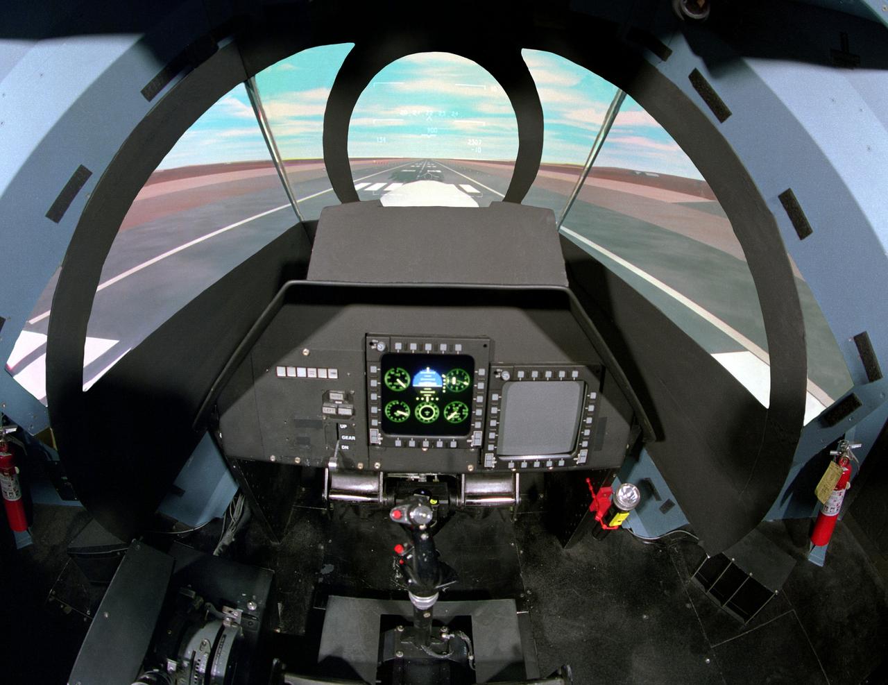
NASA Ames Vertical Motion Simulator (VMS)VMS: F-cab SIMFR (Simulation Frequency Response) Project; Pilots cockpit and out-th-window (OTW) view
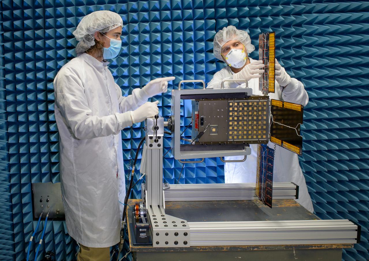
Austin Bowie, left, and Jesse Fusco fold the BioSentinel flight unit solar array in the Engineering Evaluation Laboratory, or EEL, Radio Frequency test facility, N244, after completion of an electromagnetic compatibility test procedure.
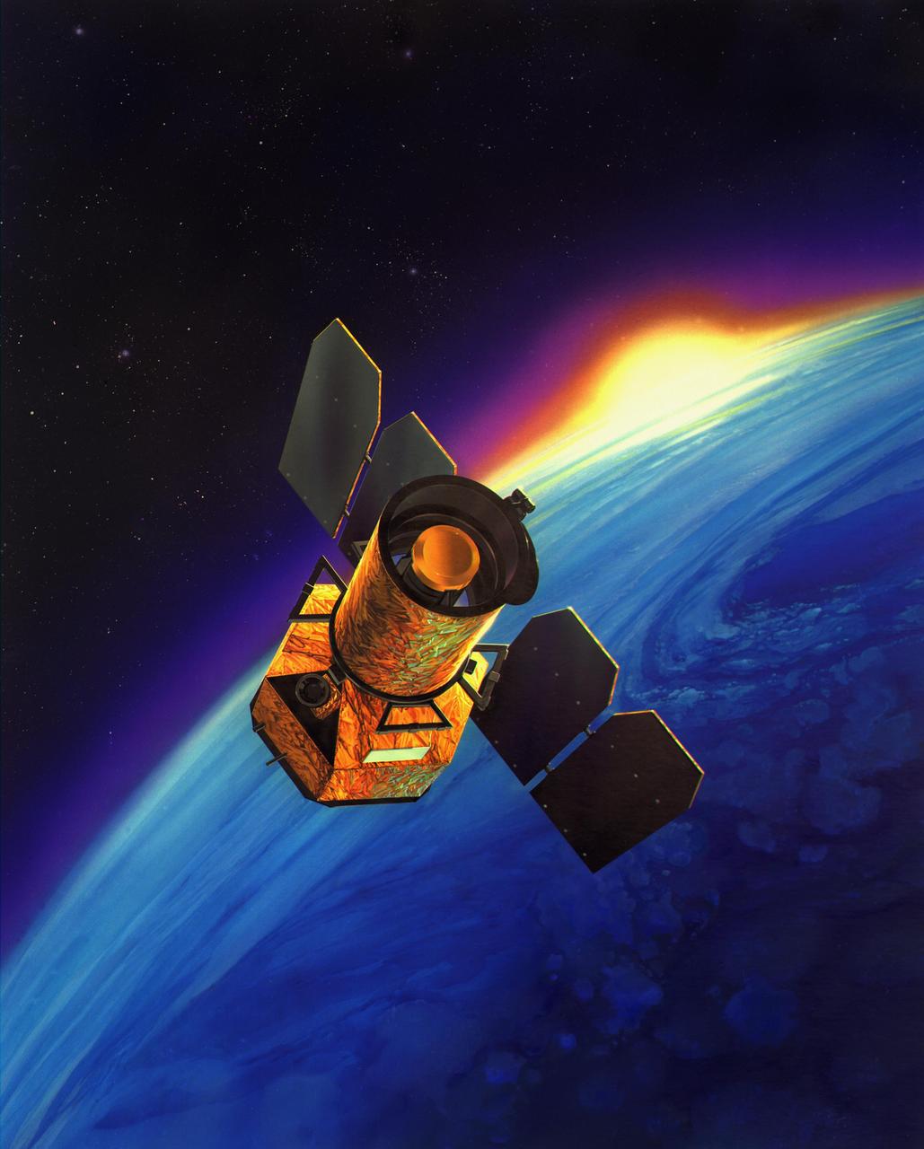
The Galaxy Evolution Explorer was launched on April 28, 2003. Its mission is to study the shape, brightness, size and distance of galaxies across 10 billion years of cosmic history. The 50-centimeter-diameter (19.7-inch) telescope onboard the Galaxy Evolution Explorer sweeps the skies in search of ultraviolet-light sources. Ultraviolet is light from the higher end of the electromagnetic spectrum, just above visible light in frequency, but below X-rays and gamma rays. While a small amount of ultraviolet penetrates Earth's atmosphere, causing sunburn, the Galaxy Evolution Explorer observes those ultraviolet frequencies that can only be seen from space. http://photojournal.jpl.nasa.gov/catalog/PIA04234
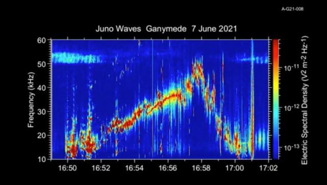
This 50-second animation provides an auditory as well as visual glimpse at data collected by Juno's Waves instrument as the spacecraft flew past the Jovian moon Ganymede on June 7, 2021. The abrupt change to higher frequencies around the midpoint of the recording represents the spacecraft's move from one region of Ganymede's magnetosphere to another. The audio track is made by shifting the frequency of those emissions – which range from 10 to 50 kHz – into the lower audio range. The animation is shorter than the duration of Juno's flyby because the Waves data is edited onboard to reduce telemetry requirements. Movie available at https://photojournal.jpl.nasa.gov/catalog/PIA25030
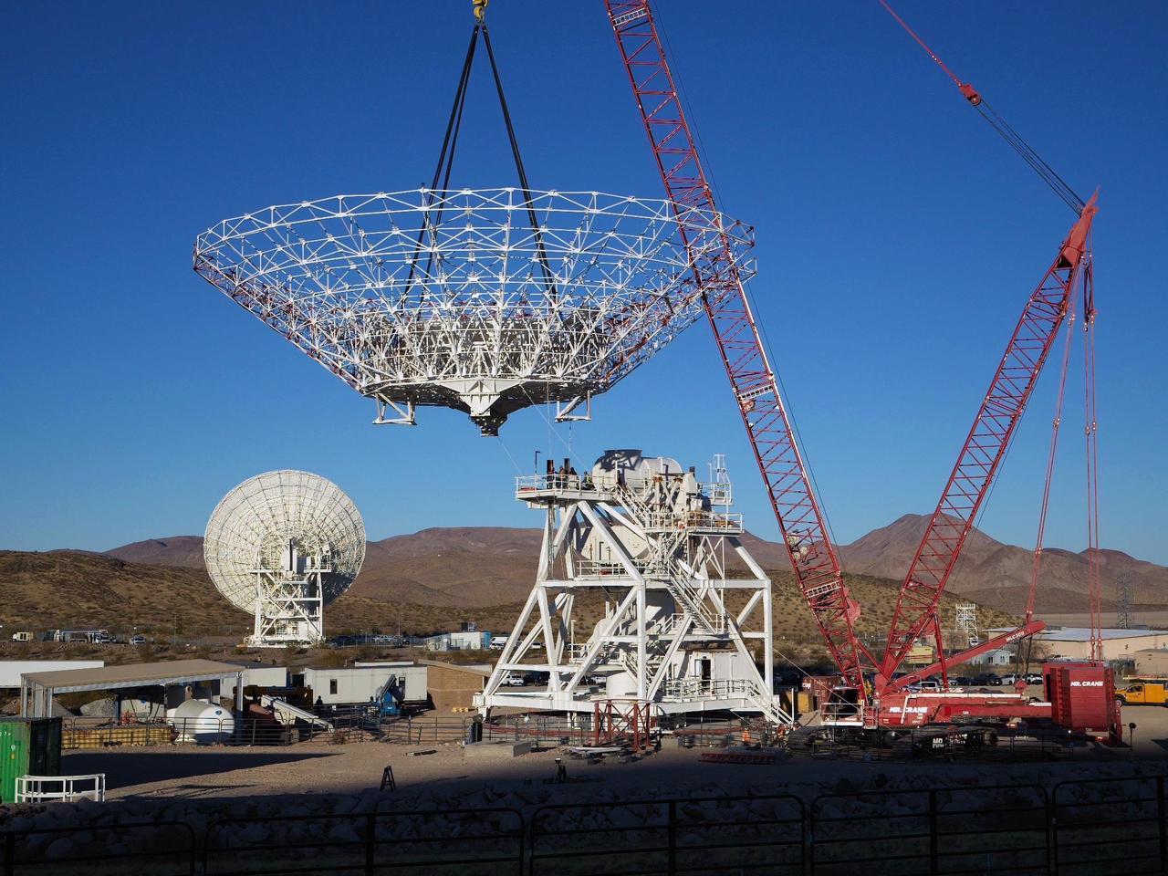
A crane lowers the 112-foot-wide (34-meter-wide) steel framework for the Deep Space Station 23 (DSS-23) reflector dish into position on Dec. 18, 2024, at the Deep Space Network's Goldstone Space Communications Complex near Barstow, California. A multi-frequency beam waveguide antenna, DSS-23 will boost the DSN's capacity and enhance NASA's deep space communications capabilities for decades to come. Once online in 2026, DSS-23 will be the fifth of six new beam waveguide antennas to be added to the network, following DSS-53, which was added at the DSN's Madrid complex in 2022. After the reflector skeleton was bolted into place, engineers placed what's called a quadripod into the center of the structure. A four-legged support structure weighing 16 ½ tons, the quadripod is fitted with a curved subreflector that will direct radio frequency signals from deep space that bounce off the main reflector into the antenna's pedestal where the antenna's receivers are housed. Next steps: to fit panels onto the steel skeleton of the parabolic reflector to create a curved surface to collect radio frequency signals. The DSN allows missions to track, send commands to, and receive scientific data from faraway spacecraft. It is managed by NASA's Jet Propulsion Laboratory in Southern California for the agency's Space Communications and Navigation (SCaN) program, which is located at NASA Headquarters within the Space Operations Mission Directorate. https://photojournal.jpl.nasa.gov/catalog/PIA26454
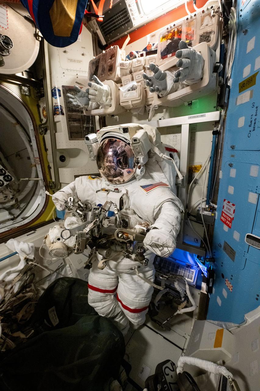
iss072e518456 (Jan. 23, 2025) --- A spacesuit is pictured staged inside the International Space Station's Quest airlock ahead of a spacewalk planned for NASA astronauts Suni Williams and Butch Wilmore. The two spacewalkers are scheduled to exit the Quest airlock on Jan. 30 to remove a radio frequency group antenna assembly and search for microbes outside the orbital outpost.
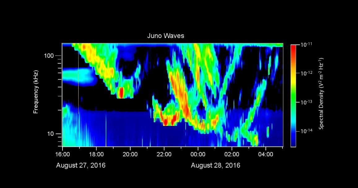
During its close flyby of Jupiter on August 27, 2016, the Waves instrument on NASA's Juno spacecraft received radio signals associated with the giant planet's very intense auroras. This video displays these radio emissions in a format similar to a voiceprint, showing the intensity of radio waves as a function of frequency and time. The largest intensities are indicated in warmer colors. The frequency range of these signals is from 7 to 140 kilohertz. Radio astronomers call these "kilometric emissions" because their wavelengths are about a kilometer long. The time span of this data is 13 hours, beginning shortly after Juno's closest approach to Jupiter. Accompanying this data display is an audio rendition of the radio emissions, shifted into a lower register since the radio waves are well above the audio frequency range. In the video, a cursor moves from left to right to mark the time as the sounds are heard. These radio emissions were among the first observed by early radio astronomers in the 1950s. However, until now, they had not been observed from closely above the auroras themselves. From its polar orbit vantage point, Juno has -- for the first time -- enabled observations of these emissions from very close range. The Juno team believes that Juno flew directly through the source regions for some of these emissions during this flyby, which was Juno's first with its sensors actively collecting data. A movie is available at http://photojournal.jpl.nasa.gov/catalog/PIA21037

iss070e027402 (Nov. 17, 2023) --- NASA astronaut and Expedition 70 Flight Engineer Jasmin Moghbeli works in the Harmony module and calibrates an ultrasonic inspection device that uses high-frequency sound waves to analyze materials aboard the International Space Station.
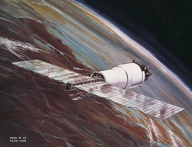
This image is an artist's conception of the Pegasus, meteoroid detection satellite, in orbit with meteoroid detector extended. The satellite, a payload for Saturn I SA-8, SA-9, and SA-10 missions, was used to obtain data on frequency and penetration of the potentially hazardous micrometeoroids in low Earth orbits and to relay the information back to Earth.
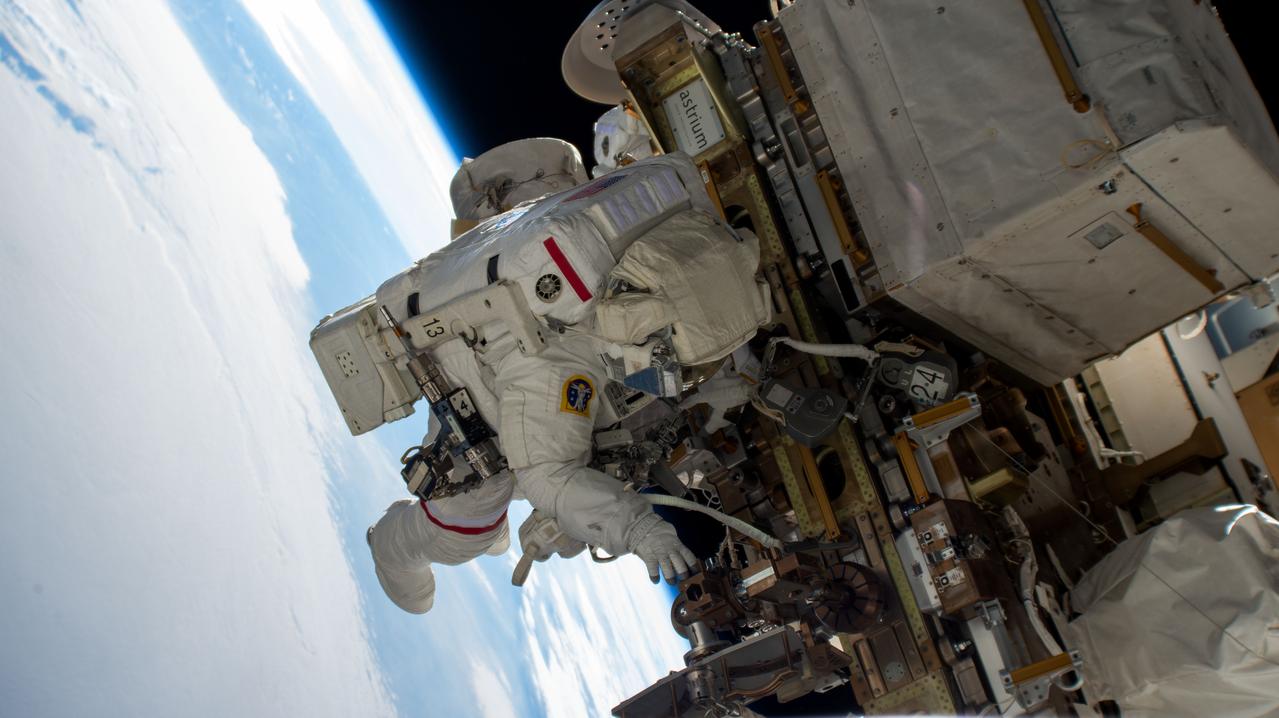
iss072e574856 (Jan. 30, 2025) --- NASA astronaut and Expedition 72 Commander Suni Williams works outside the International Space Station during a five-hour and 26-minute spacewalk to remove and stow a radio frequency group antenna assembly. The orbital outpost was soaring 260 miles above Kazakhstan at the time of this photograph.
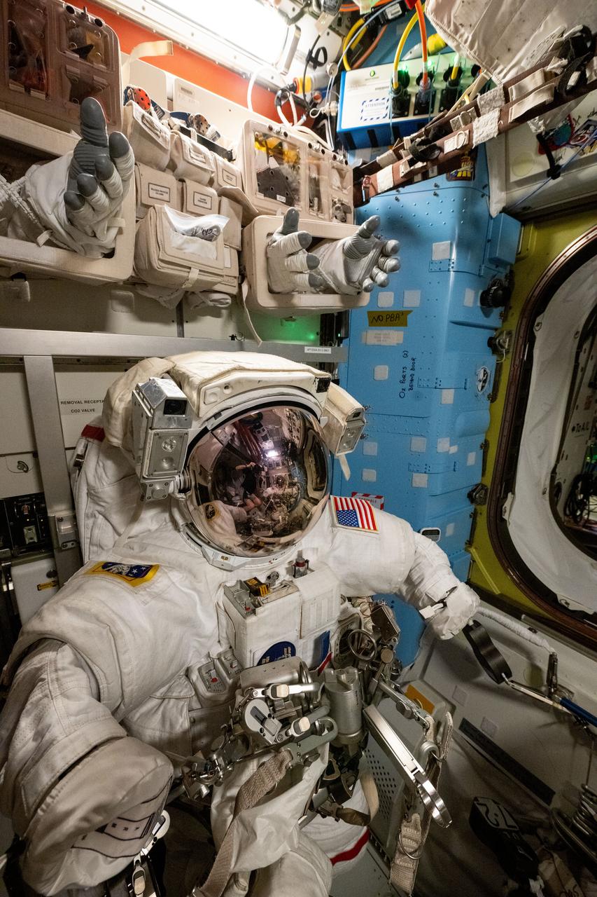
iss072e518461 (Jan. 23, 2025) --- A spacesuit is pictured staged inside the International Space Station's Quest airlock ahead of a spacewalk planned for NASA astronauts Suni Williams and Butch Wilmore. The two spacewalkers are scheduled to exit the Quest airlock on Jan. 30 to remove a radio frequency group antenna assembly and search for microbes outside the orbital outpost. At top, spacesuit gloves are stowed above the spacesuits for easy access when astronauts are preparing to begin a spacewalk.
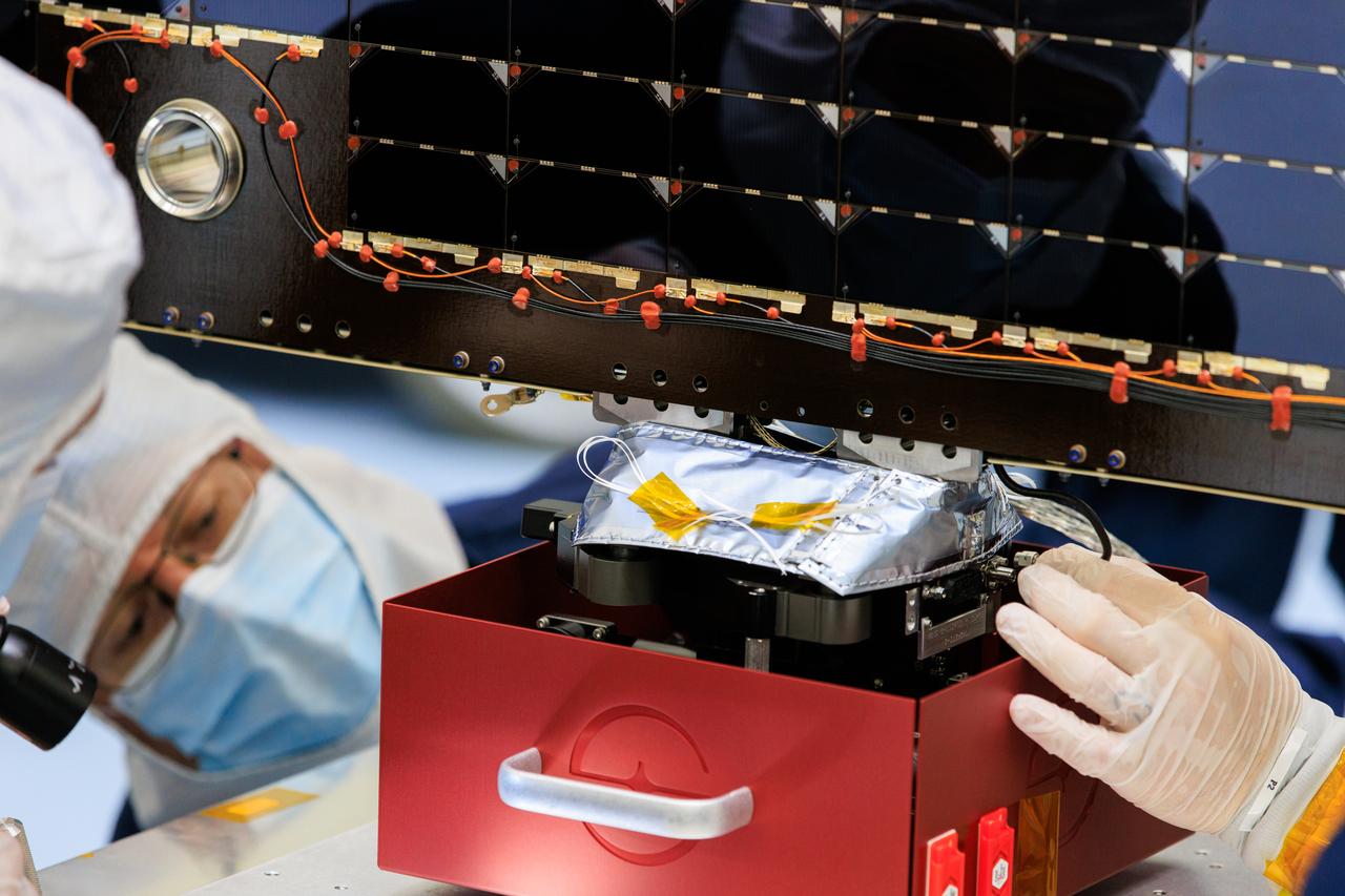
Technicians inside the Payload Hazardous Servicing Facility at NASA’s Kennedy Space Center in Florida install and test one of several antennas on a solar array Wednesday, March 20, 2024, for the agency’s Europa Clipper spacecraft which will study Jupiter’s icy moon, Europa, to determine if the planet can support life. REASON, (Radar for Europa Assessment and Sounding: Ocean to Near-surface) instrument will use the antennas to send both very high frequency radio waves and high frequency to penetrate up to 18 miles (30 kilometers) deep to search the ocean, measure ice thickness, and study the topography, composition, and roughness of Europa’s surface. The Europa Clipper spacecraft will ship to Florida later this year from NASA’s Jet Propulsion Lab in Southern California in preparation for launch aboard a SpaceX Falcon Heavy rocket from Kennedy’s Launch Complex 39A targeting October 2024.
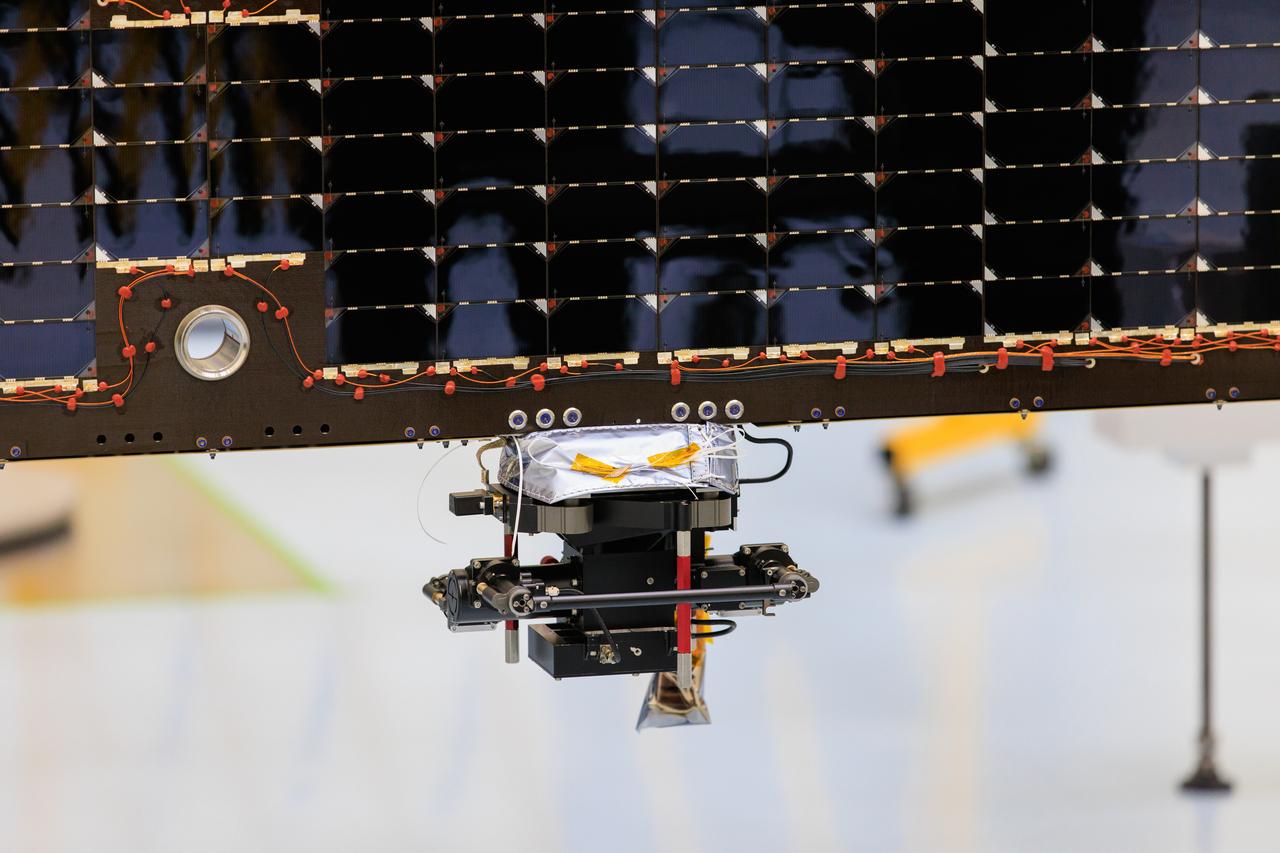
An antenna for the REASON, (Radar for Europa Assessment and Sounding: Ocean to Near-surface) instrument attaches to a solar array for NASA’s Europa Clipper spacecraft inside the Payload Hazardous Servicing Facility at the agency’s Kennedy Space Center in Florida on Wednesday, March 20, 2024. The Europa Clipper spacecraft will study Jupiter’s icy moon Europa, and the REASON instrument will use the antennas to send both both High Frequency (HF) and Very High Frequency (VHF) radio waves to penetrate up to 18 miles (30 kilometers) deep and search the ocean, measure ice thickness, and study the topography, composition, and roughness of Europa’s surface. The Europa Clipper spacecraft will ship to Florida later this year from NASA’s Jet Propulsion Lab in Southern California in preparation for launch aboard a SpaceX Falcon Heavy rocket from Kennedy’s Launch Complex 39A, targeting October.
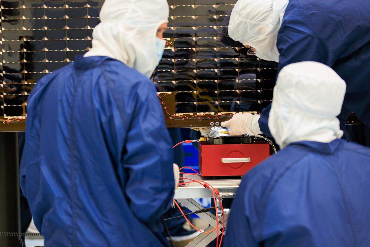
Technicians inside the Payload Hazardous Servicing Facility at NASA’s Kennedy Space Center in Florida install and test one of several antennas on a solar array Wednesday, March 20, 2024, for the agency’s Europa Clipper spacecraft which will study Jupiter’s icy moon Europa to determine if the planet has conditions that could support life. REASON, (Radar for Europa Assessment and Sounding: Ocean to Near-surface) instrument will use the antennas to send both High Frequency (HF) and Very High Frequency (VHF) radio waves to penetrate up to 18 miles (30 kilometers) deep and search the ocean, measure ice thickness, and study the topography, composition, and roughness of Europa’s surface. The Europa Clipper spacecraft will ship to Florida later this year from NASA’s Jet Propulsion Lab in Southern California in preparation for launch aboard a SpaceX Falcon Heavy rocket from Kennedy’s Launch Complex 39A targeting October 2024.
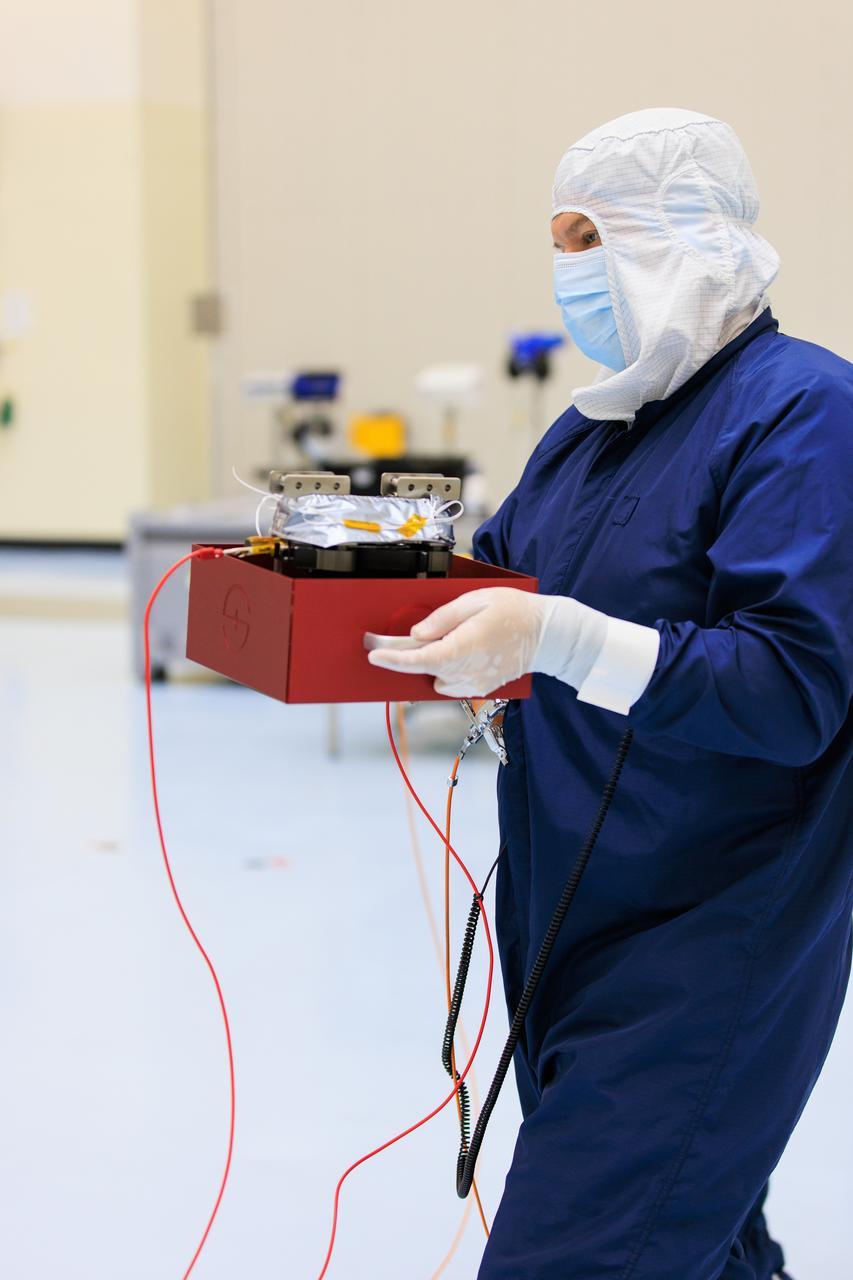
On Wednesday, March 20, 2024, a technician inside the Payload Hazardous Servicing Facility at NASA’s Kennedy Space Center in Florida carries an antenna that will attach to a solar array for the agency’s Europa Clipper spacecraft, which will study Jupiter’s icy moon Europa to determine if the planet has conditions that could support life. The REASON, (Radar for Europa Assessment and Sounding: Ocean to Near-surface) instrument will use the antennas to send both High Frequency (HF) and Very High Frequency (VHF) radio waves to penetrate up to 18 miles (30 kilometers) deep and search the ocean, measure ice thickness, and study the topography, composition, and roughness of Europa’s surface. The Europa Clipper spacecraft will ship to Florida later this year from NASA’s Jet Propulsion Lab in Southern California in preparation for launch aboard a SpaceX Falcon Heavy rocket from Kennedy’s Launch Complex 39A targeting October 2024.
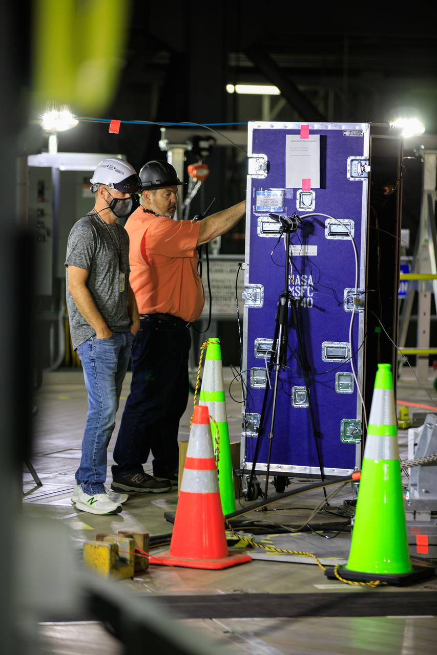
Artemis teams members perform the integrated modal test of the Space Launch System and mobile launcher in High Bay 3 of the Vehicle Assembly Building at NASA’s Kennedy Space Center in Florida on Sept. 24, 2021. The tests will help determine the natural frequencies of the recently stacked rocket before launch of the Artemis I mission. The data also will be used to help steer the rocket during flight. To identify the rocket’s natural frequencies, the team placed about 300 sensors on it and the mobile launcher to detect, record, and transmit the information, along with hydraulic shakers attached to seven locations on the rocket. Artemis I will be the first integrated test of the SLS and Orion spacecraft. In later missions, NASA will land the first woman and the first person of color on the surface of the Moon, paving the way for a long-term lunar presence and serving as a steppingstone on the way to Mars.
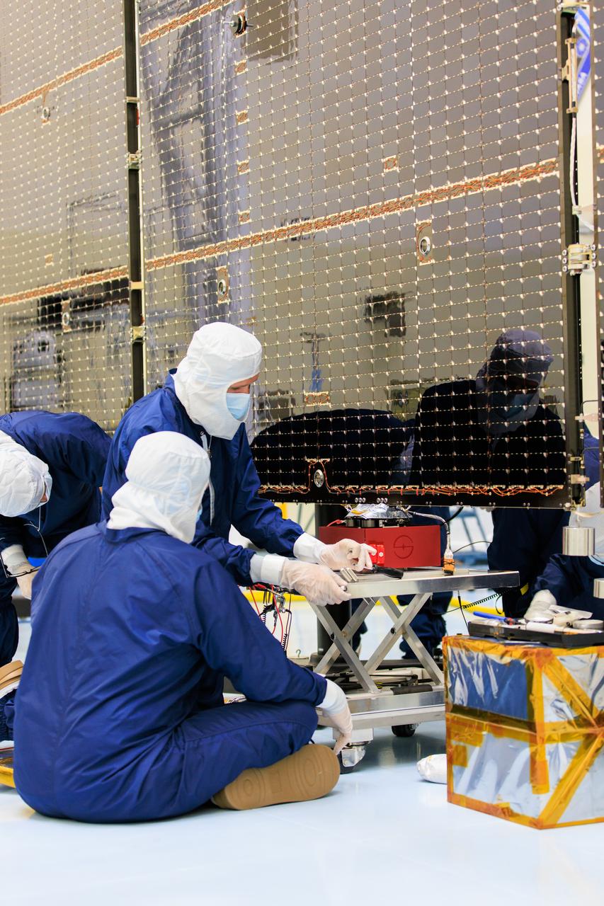
Technicians inside the Payload Hazardous Servicing Facility at NASA’s Kennedy Space Center in Florida install and test one of several antennas on a solar array Wednesday, March 20, 2024, for the agency’s Europa Clipper spacecraft which will study Jupiter’s icy moon Europa to determine if the planet has conditions that could support life. REASON, (Radar for Europa Assessment and Sounding: Ocean to Near-surface) instrument will use the antennas to send both High Frequency (HF) and Very High Frequency (VHF) radio waves to penetrate up to 18 miles (30 kilometers) deep and search the ocean, measure ice thickness, and study the topography, composition, and roughness of Europa’s surface. The Europa Clipper spacecraft will ship to Florida later this year from NASA’s Jet Propulsion Lab in Southern California in preparation for launch aboard a SpaceX Falcon Heavy rocket from Kennedy’s Launch Complex 39A targeting October 2024.
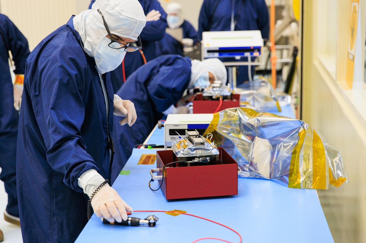
Technicians inside the Payload Hazardous Servicing Facility at NASA’s Kennedy Space Center in Florida test antennas on Wednesday, March 20, 2024, shortly before installing them on a solar array for the agency’s Europa Clipper spacecraft, which will study Jupiter’s icy moon Europa to determine if the planet has conditions that could support life. The REASON, (Radar for Europa Assessment and Sounding: Ocean to Near-surface) instrument will use the antennas to send both High Frequency (HF) and Very High Frequency (VHF) to penetrate up to 18 miles (30 kilometers) deep and search the ocean, measure ice thickness, and study the topography, composition, and roughness of Europa’s surface. The Europa Clipper spacecraft will ship to Florida later this year from NASA’s Jet Propulsion Lab in Southern California in preparation for launch aboard a SpaceX Falcon Heavy rocket from Kennedy’s Launch Complex 39A targeting October 2024.

jsc2021e022515 (June 11, 2021) --- NASA’s Exploration Extravehicular Mobility Unit (xEMU) spacesuit undergoes antenna testing in NASA Johnson Space Center’s anechoic chamber to inspect multi-layer insulation keep-out zones for the Wi-Fi and ultra-high-frequency antennas that are part of the spacesuit’s communication system. The xEMU test article is named xGUS, the successor to the Extravehicular Mobility Unit test article (also named GUS), which was named after NASA astronaut Gus Grissom and his iconic silver spacesuit. This image was taken from where the "horn," or source antenna, is located that sends out radio frequency signals to the spacesuit. The anechoic chamber walls are covered with a material that absorbs electromagnetic energy allowing the anechoic chamber to simulate a space environment. The antenna test facility is utilized to test antenna radiation distribution pattern performance for spaceflight applications in electromagnetic environments. Pictured in the photo is antenna test engineer Will Bond.
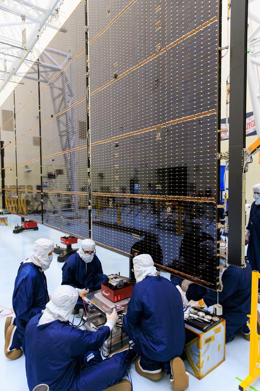
Technicians inside the Payload Hazardous Servicing Facility at NASA’s Kennedy Space Center in Florida install and test one of several antennas on a solar array Wednesday, March 20, 2024, for the agency’s Europa Clipper spacecraft which will study Jupiter’s icy moon Europa to determine if the planet has conditions that could support life. REASON, (Radar for Europa Assessment and Sounding: Ocean to Near-surface) instrument will use the antennas to send both High Frequency (HF) and Very High Frequency (VHF) radio waves to penetrate up to 18 miles (30 kilometers) deep and search the ocean, measure ice thickness, and study the topography, composition, and roughness of Europa’s surface. The Europa Clipper spacecraft will ship to Florida later this year from NASA’s Jet Propulsion Lab in Southern California in preparation for launch aboard a SpaceX Falcon Heavy rocket from Kennedy’s Launch Complex 39A targeting October 2024.
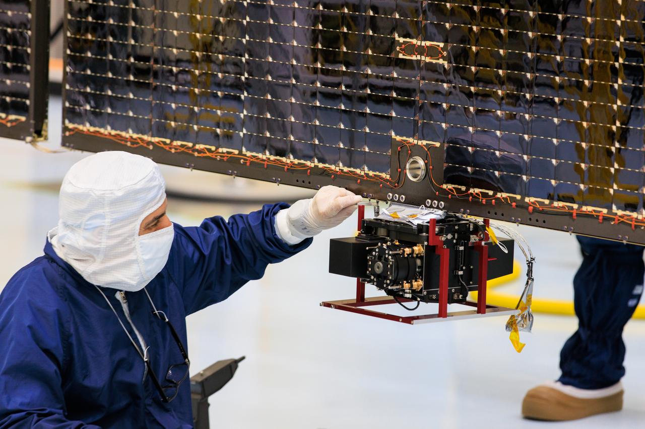
Technicians inside the Payload Hazardous Servicing Facility at NASA’s Kennedy Space Center in Florida install and test antennas on a solar array on Wednesday, March 20, 2024, for the agency’s Europa Clipper spacecraft which will study Jupiter’s icy moon Europa to determine if the planet has conditions that could support life. The REASON, (Radar for Europa Assessment and Sounding: Ocean to Near-surface) instrument will use the antennas to send both High Frequency (HF) and Very High Frequency (VHF) radio waves to penetrate up to 18 miles (30 kilometers) deep and search the ocean, measure ice thickness, and study the topography, composition, and roughness of Europa’s surface. The Europa Clipper spacecraft will ship to Florida later this year from NASA’s Jet Propulsion Lab in Southern California in preparation for launch aboard a SpaceX Falcon Heavy rocket from Kennedy’s Launch Complex 39A targeting October.
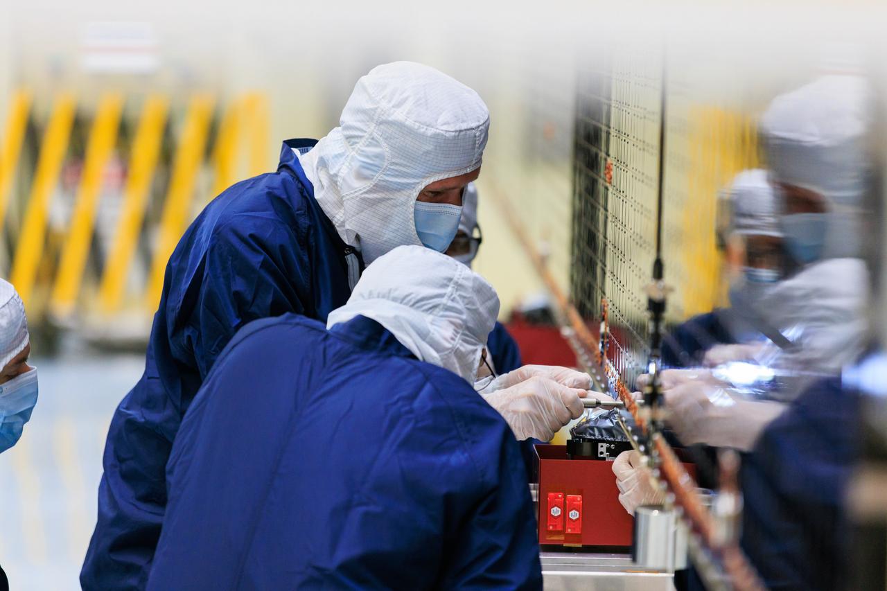
Technicians inside the Payload Hazardous Servicing Facility at NASA’s Kennedy Space Center in Florida install and test one of several antennas on a solar array Wednesday, March 20, 2024, for the agency’s Europa Clipper spacecraft which will study Jupiter’s icy moon Europa to determine if the planet has conditions that could support life. REASON, (Radar for Europa Assessment and Sounding: Ocean to Near-surface) instrument will use the antennas to send both High Frequency (HF) and Very High Frequency (VHF) radio waves to penetrate up to 18 miles (30 kilometers) deep and search the ocean, measure ice thickness, and study the topography, composition, and roughness of Europa’s surface. The Europa Clipper spacecraft will ship to Florida later this year from NASA’s Jet Propulsion Lab in Southern California in preparation for launch aboard a SpaceX Falcon Heavy rocket from Kennedy’s Launch Complex 39A targeting October 2024.
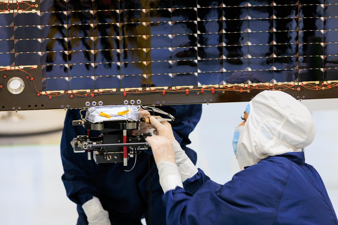
Technicians inside the Payload Hazardous Servicing Facility at NASA’s Kennedy Space Center in Florida install and test antennas on a solar array on Wednesday, March 20, 2024, for the agency’s Europa Clipper spacecraft which will study Jupiter’s icy moon Europa to determine if the planet has conditions that could support life. The REASON, (Radar for Europa Assessment and Sounding: Ocean to Near-surface) instrument will use the antennas to send both both High Frequency (HF) and Very High Frequency (VHF) radio waves to penetrate up to 18 miles (30 kilometers) deep and search the ocean, measure ice thickness, and study the topography, composition, and roughness of Europa’s surface. The Europa Clipper spacecraft will ship to Florida later this year from NASA’s Jet Propulsion Lab in Southern California in preparation for launch aboard a SpaceX Falcon Heavy rocket from Kennedy’s Launch Complex 39A targeting October.
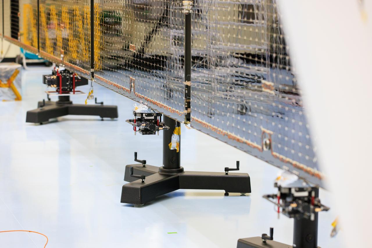
Technicians inside the Payload Hazardous Servicing Facility at NASA’s Kennedy Space Center in Florida install and test antennas on a solar array on Wednesday, March 20, 2024, for the agency’s Europa Clipper spacecraft which will study Jupiter’s icy moon Europa to determine if the planet has conditions that could support life. The REASON, (Radar for Europa Assessment and Sounding: Ocean to Near-surface) instrument will use the antennas to send both High Frequency (HF) and Very High Frequency (VHF) radio waves to penetrate up to 18 miles (30 kilometers) deep and search the ocean, measure ice thickness, and study the topography, composition, and roughness of Europa’s surface. The Europa Clipper spacecraft will ship to Florida later this year from NASA’s Jet Propulsion Lab in Southern California in preparation for launch aboard a SpaceX Falcon Heavy rocket from Kennedy’s Launch Complex 39A targeting October.
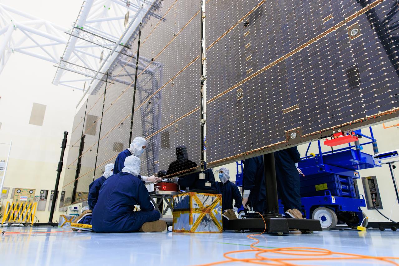
Technicians inside the Payload Hazardous Servicing Facility at NASA’s Kennedy Space Center in Florida install and test one of several antennas on a solar array Wednesday, March 20, 2024, for the agency’s Europa Clipper spacecraft which will study Jupiter’s icy moon Europa to determine if the planet has conditions that could support life. REASON, (Radar for Europa Assessment and Sounding: Ocean to Near-surface) instrument will use the antennas to send both High Frequency (HF) and Very High Frequency (VHF) radio waves to penetrate up to 18 miles (30 kilometers) deep and search the ocean, measure ice thickness, and study the topography, composition, and roughness of Europa’s surface. The Europa Clipper spacecraft will ship to Florida later this year from NASA’s Jet Propulsion Lab in Southern California in preparation for launch aboard a SpaceX Falcon Heavy rocket from Kennedy’s Launch Complex 39A targeting October 2024.
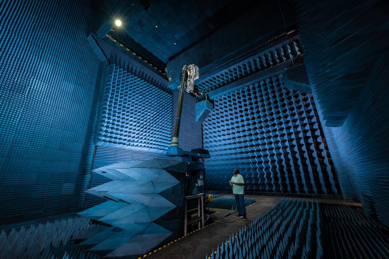
jsc2021e022488 (June 11, 2021) --- NASA’s Exploration Extravehicular Mobility Unit (xEMU) spacesuit undergoes antenna testing in NASA Johnson Space Center’s anechoic chamber to inspect multi-layer insulation keep-out zones for the Wi-Fi and ultra-high-frequency antennas that are part of the spacesuit’s communication system. The xEMU test article is named xGUS, the successor to the Extravehicular Mobility Unit test article (also named GUS), which was named after NASA astronaut Gus Grissom and his iconic silver spacesuit. This image was taken from where the "horn," or source antenna, is located that sends out radio frequency signals to the spacesuit. The anechoic chamber walls are covered with a material that absorbs electromagnetic energy allowing the anechoic chamber to simulate a space environment. The antenna test facility is utilized to test antenna radiation distribution pattern performance for spaceflight applications in electromagnetic environments. Pictured in the photo is antenna test engineer Will Bond.
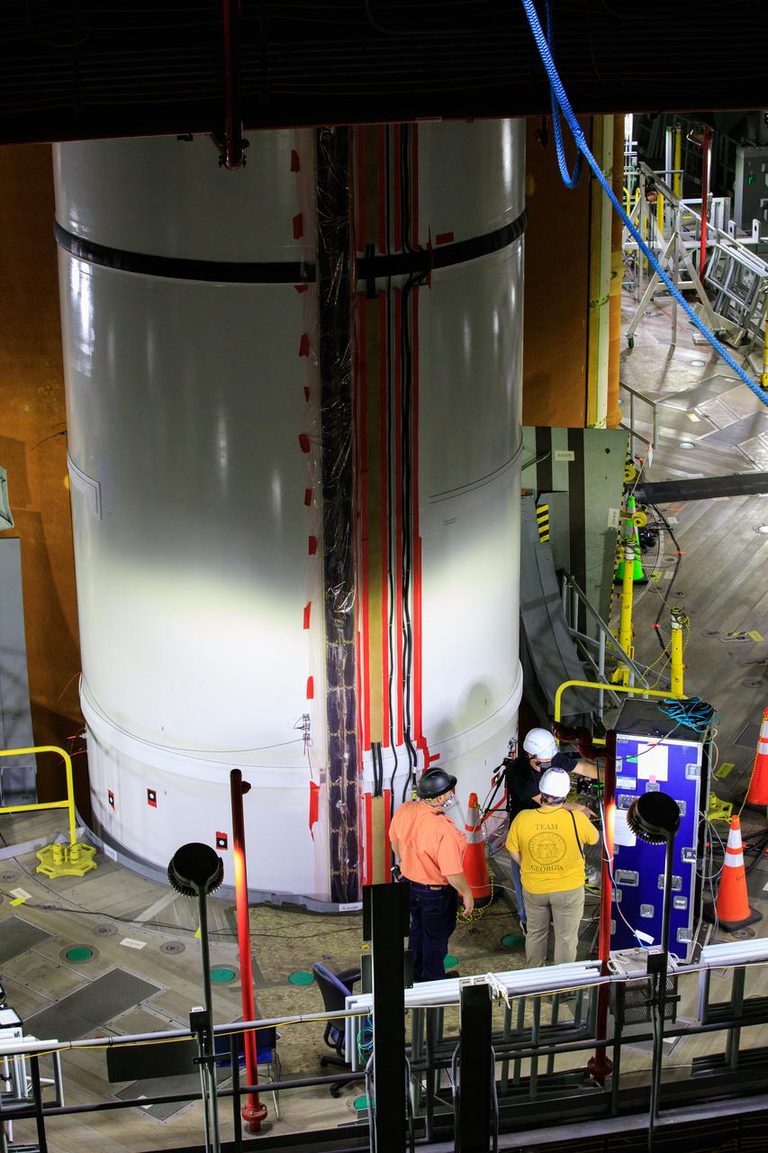
Artemis teams members perform the integrated modal test of the Space Launch System and mobile launcher in High Bay 3 of the Vehicle Assembly Building at NASA’s Kennedy Space Center in Florida on Sept. 24, 2021. The tests will help determine the natural frequencies of the recently stacked rocket before launch of the Artemis I mission. The data also will be used to help steer the rocket during flight. To identify the rocket’s natural frequencies, the team placed about 300 sensors on it and the mobile launcher to detect, record, and transmit the information, along with hydraulic shakers attached to seven locations on the rocket. Artemis I will be the first integrated test of the SLS and Orion spacecraft. In later missions, NASA will land the first woman and the first person of color on the surface of the Moon, paving the way for a long-term lunar presence and serving as a steppingstone on the way to Mars.
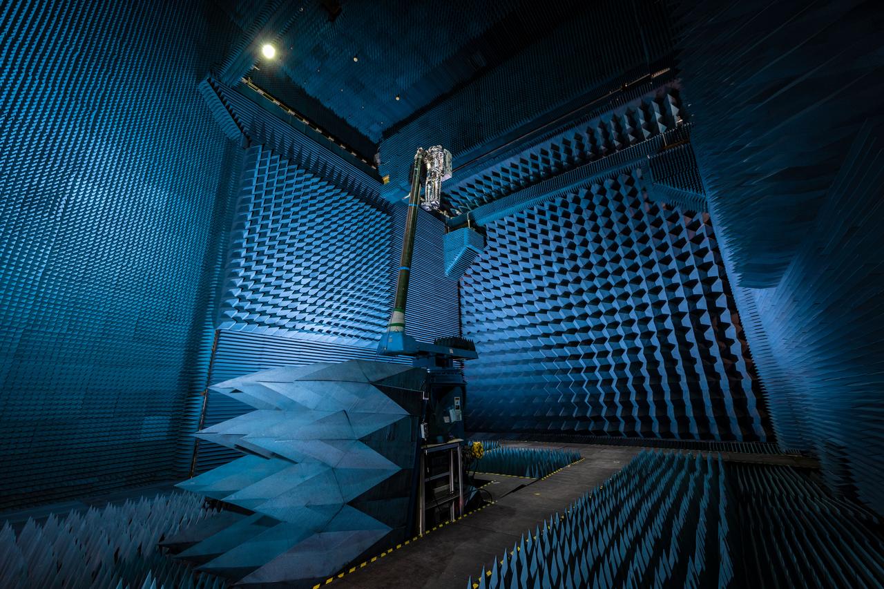
jsc2021e022487 (June 11, 2021) --- NASA’s Exploration Extravehicular Mobility Unit (xEMU) spacesuit undergoes antenna testing in NASA Johnson Space Center’s anechoic chamber to inspect multi-layer insulation keep-out zones for the Wi-Fi and ultra-high-frequency antennas that are part of the spacesuit’s communication system. The xEMU test article is named xGUS, the successor to the Extravehicular Mobility Unit test article (also named GUS), which was named after NASA astronaut Gus Grissom and his iconic silver spacesuit. This image was taken from where the "horn," or source antenna, is located that sends out radio frequency signals to the spacesuit. The anechoic chamber walls are covered with a material that absorbs electromagnetic energy allowing the anechoic chamber to simulate a space environment. The antenna test facility is utilized to test antenna radiation distribution pattern performance for spaceflight applications in electromagnetic environments.
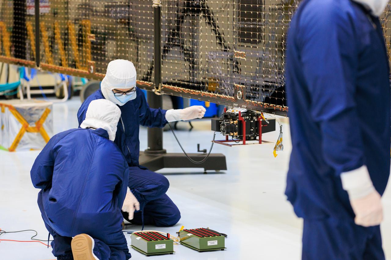
Technicians inside the Payload Hazardous Servicing Facility at NASA’s Kennedy Space Center in Florida install and test antennas on a solar array on Wednesday, March 20, 2024, for the agency’s Europa Clipper spacecraft which will study Jupiter’s icy moon Europa to determine if the planet has conditions that could support life. The REASON, (Radar for Europa Assessment and Sounding: Ocean to Near-surface) instrument will use the antennas to send both High Frequency (HF) and Very High Frequency (VHF) radio waves to penetrate up to 18 miles (30 kilometers) deep and search the ocean, measure ice thickness, and study the topography, composition, and roughness of Europa’s surface. The Europa Clipper spacecraft will ship to Florida later this year from NASA’s Jet Propulsion Lab in Southern California in preparation for launch aboard a SpaceX Falcon Heavy rocket from Kennedy’s Launch Complex 39A targeting October.
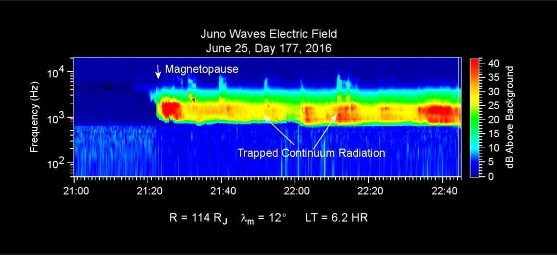
This chart presents data that the Waves investigation on NASA's Juno spacecraft recorded as the spacecraft crossed the bow shock just outside of Jupiter's magnetosphere on June 24, 2016, while approaching Jupiter. Audio accompanies the animation, with volume and pitch correlated to the amplitude and frequency of the recorded waves. The graph is a frequency-time spectrogram with color coding to indicate wave amplitudes as a function of wave frequency (vertical axis, in hertz) and time (horizontal axis, with a total elapsed time of two hours). During the hour before Juno reached the bow shock, the Waves instrument was detecting mainly plasma oscillations just below 10,000 hertz (10 kilohertz). The frequency of these oscillations is related to the local density of electrons; the data yield an estimate of approximately one electron per cubic centimeter (about 16 per cubic inch) in this region just outside Jupiter's bow shock. The broadband burst of noise marked "Bow Shock" is the region of turbulence where the supersonic solar wind is heated and slowed by encountering the Jovian magnetosphere. The shock is analogous to a sonic boom generated in Earth's atmosphere by a supersonic aircraft. The region after the shock is called the magnetosheath. The vertical bar to the right of the chart indicates the color coding of wave amplitude, in decibels (dB) above the background level detected by the Waves instrument. Each step of 10 decibels marks a tenfold increase in wave power. When Juno collected these data, the distance from the spacecraft to Jupiter was about 5.56 million miles (8.95 million kilometers), indicated on the chart as 128 times the radius of Jupiter. Jupiter's magnetic field is tilted about 10 degrees from the planet's axis of rotation. The note of 22 degrees on the chart indicates that at the time these data were recorded, the spacecraft was 22 degrees north of the magnetic-field equator. The "LT" notation is local time on Jupiter at the longitude of the planet directly below the spacecraft, with a value of 6.2 indicating approximately dawn. http://photojournal.jpl.nasa.gov/catalog/PIA20753
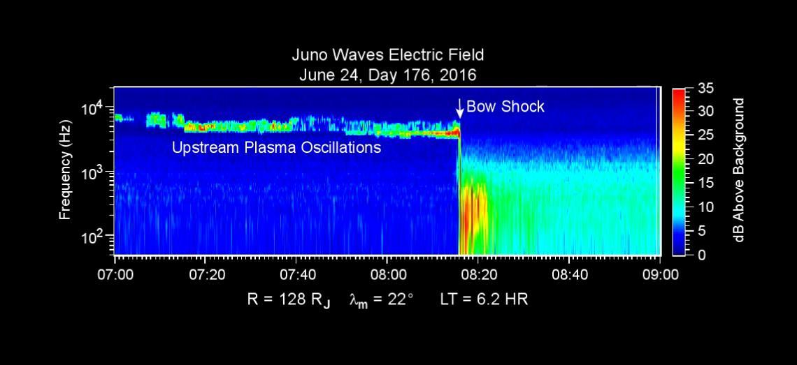
This chart presents data that the Waves investigation on NASA's Juno spacecraft recorded as the spacecraft crossed the bow shock just outside of Jupiter's magnetosphere on June 24, 2016, while approaching Jupiter. Audio accompanies the animation, with volume and pitch correlated to the amplitude and frequency of the recorded waves. The graph is a frequency-time spectrogram with color coding to indicate wave amplitudes as a function of wave frequency (vertical axis, in hertz) and time (horizontal axis, with a total elapsed time of two hours). During the hour before Juno reached the bow shock, the Waves instrument was detecting mainly plasma oscillations just below 10,000 hertz (10 kilohertz). The frequency of these oscillations is related to the local density of electrons; the data yield an estimate of approximately one electron per cubic centimeter (about 16 per cubic inch) in this region just outside Jupiter's bow shock. The broadband burst of noise marked "Bow Shock" is the region of turbulence where the supersonic solar wind is heated and slowed by encountering the Jovian magnetosphere. The shock is analogous to a sonic boom generated in Earth's atmosphere by a supersonic aircraft. The region after the shock is called the magnetosheath. The vertical bar to the right of the chart indicates the color coding of wave amplitude, in decibels (dB) above the background level detected by the Waves instrument. Each step of 10 decibels marks a tenfold increase in wave power. When Juno collected these data, the distance from the spacecraft to Jupiter was about 5.56 million miles (8.95 million kilometers), indicated on the chart as 128 times the radius of Jupiter. Jupiter's magnetic field is tilted about 10 degrees from the planet's axis of rotation. The note of 22 degrees on the chart indicates that at the time these data were recorded, the spacecraft was 22 degrees north of the magnetic-field equator. The "LT" notation is local time on Jupiter at the longitude of the planet directly below the spacecraft, with a value of 6.2 indicating approximately dawn. http://photojournal.jpl.nasa.gov/catalog/PIA20753
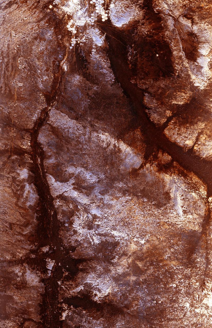
The ability of a sophisticated radar instrument to image large regions of the world from space, using different frequencies that can penetrate dry sand cover, produced the discovery in this image: a previously unknown branch of an ancient river, buried under thousands of years of windblown sand in a region of the Sahara Desert in North Africa. This area is near the Kufra Oasis in southeast Libya, centered at 23.3 degrees north latitude, 22.9 degrees east longitude. The image was acquired by the Spaceborne Imaging Radar-C/X-band Synthetic Aperture (SIR-C/X-SAR) imaging radar when it flew aboard the space shuttle Endeavour on its 60th orbit on October 4, 1994. This SIR-C image reveals a system of old, now inactive stream valleys, called "paleodrainage systems, http://photojournal.jpl.nasa.gov/catalog/PIA01310
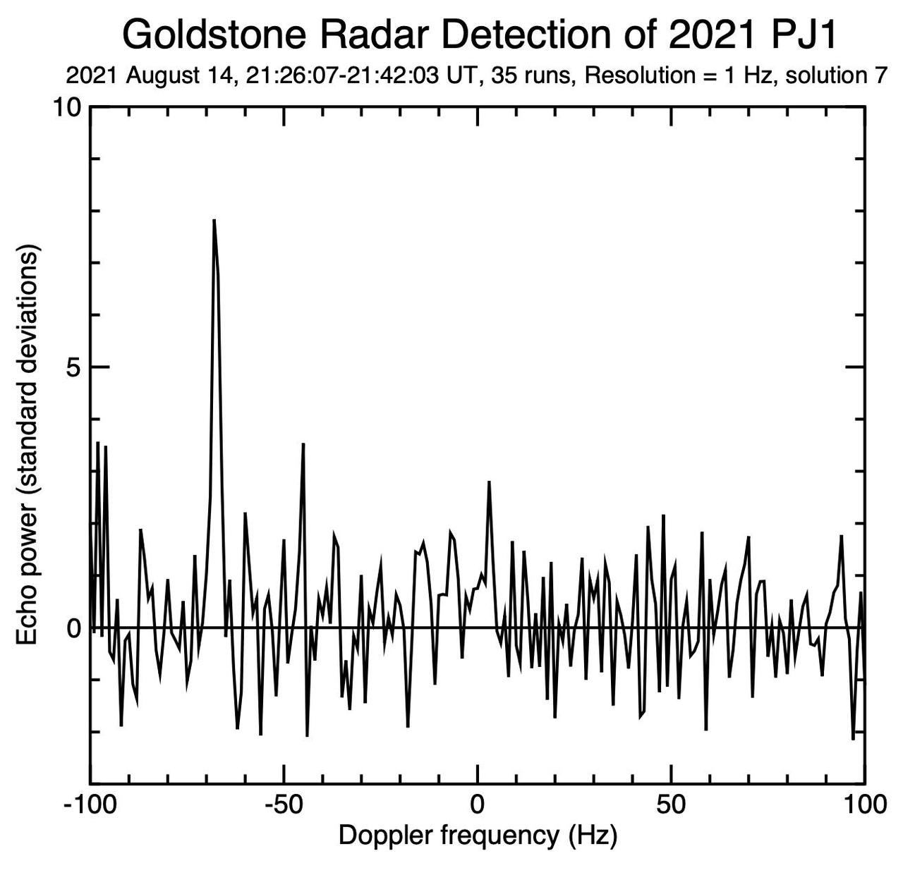
This figure represents the 1,000th near-Earth asteroid (NEA) to be detected by planetary radar since 1968. Being only 65 to 100 feet (20 to 30 meters) wide, asteroid 2021 PJ1 was too small to be imaged in any detail, but the powerful 70-meter (230-foot) Deep Space Station 14 (DSS-14) antenna at the Deep Space Network's Goldstone Deep Space Complex near Barstow, California, was able to measure the Doppler frequency of the radio waves that reflected off the object's surface. The data was recorded for 16 minutes between 2:26 p.m. and 2:42 p.m. PDT on Aug. 14, 2021. The figure shows radar echo signal strength on the vertical axis versus Doppler frequency (in units of hertz, or Hz) on the horizontal axis. The strong spike at a value of minus 70 Hz is the reflected signal (or "echo") from 2021 PJ1; the other, smaller spikes are receiver noise, which is like the static on an AM radio if there aren't any nearby stations. Using this information, scientists at NASA's Jet Propulsion Laboratory in Southern California could more accurately calculate the asteroid's velocity, its distance from Earth and its future motion around the Sun. These observations used a prediction – known as an "ephemeris" – that had relatively large uncertainties because the asteroid had been discovered only a few days earlier. If the original prediction had been perfect, the radar echo would appear at zero Hz. The fact that the radar echo is at minus 70 Hz indicates a correction could be made to the predicted velocity of minus 2.7 miles per hour (minus 1.2 meters per second). This measurement also reduced the uncertainty in the asteroid's distance from Earth from 1,300 miles (2,100 kilometers) to 5.2 miles (8.3 kilometers) – a reduction of a factor of about 250. https://photojournal.jpl.nasa.gov/catalog/PIA24563
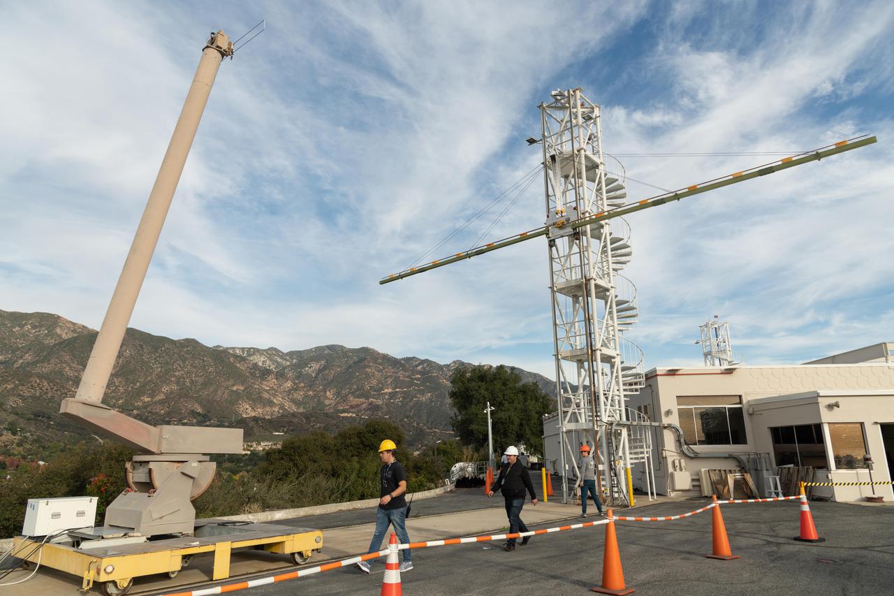
Engineers at NASA's Jet Propulsion Laboratory in Southern California test an engineering model of a high-frequency (HF) radar antenna that makes up part of NASA's Europa Clipper radar instrument on Dec. 17, 2019. The antenna is a 59-foot-long (18-meter-long) narrow copper tube held straight by several cables and a cross bar on the tower at right. In space, the copper tube will stick out straight on its own, but in Earth's gravity, the antenna requires supports to keep it straight for testing. The mobile tower at left holds a model of the VHF (very high-frequency) antenna so that engineers could measure the amount of energy coupled from one antenna to the other. Europa Clipper's radar instrument is called Radar for Europa Assessment and Sounding: Ocean to Near-surface, or REASON. As the spacecraft orbits Jupiter and surveys its icy moon Europa, REASON will use HF and VHF radio signals to penetrate up to 18 miles (30 kilometers) into the icy shell that covers Europa. The radio waves will bounce off subsurface features and return to the spacecraft to create images of the ice layers' internal structure. REASON will help scientists look for the moon's suspected ocean, measure ice thickness, and better understand the icy shell's interior. The instrument will also study the elevation, properties, and roughness of Europa's surface, and will prowl Europa's upper atmosphere for signs of plume activity. The antennae were built for NASA by Heliospace Corporation in Berkeley, California, and the University of Texas at Austin is the lead institution for REASON. The testing was conducted at JPL's Mesa Antenna Measurement Facility, which sits on a high plateau. With an internal global ocean twice the size of Earth's oceans combined, Europa may have the potential to harbor life. The Europa Clipper orbiter will swoop around Jupiter on an elliptical path, dipping close to the moon on each flyby to collect data. Understanding Europa's habitability will help scientists better understand how life developed on Earth and the potential for finding life beyond our planet. Europa Clipper is aiming for a launch readiness date of 2024. https://photojournal.jpl.nasa.gov/catalog/PIA24323

iss072e574914 (Jan. 30, 2025) --- NASA astronaut and Expedition 72 Commander Suni Williams works outside the International Space Station during a five-hour and 26-minute spacewalk to remove and stow a radio frequency group antenna assembly. In the left foreground, is the latching end effector of the Canadarm2 robotic arm. The orbital outpost was soaring 258 miles above the Pacific Ocean near the coast of Mexico at the time of this photograph.
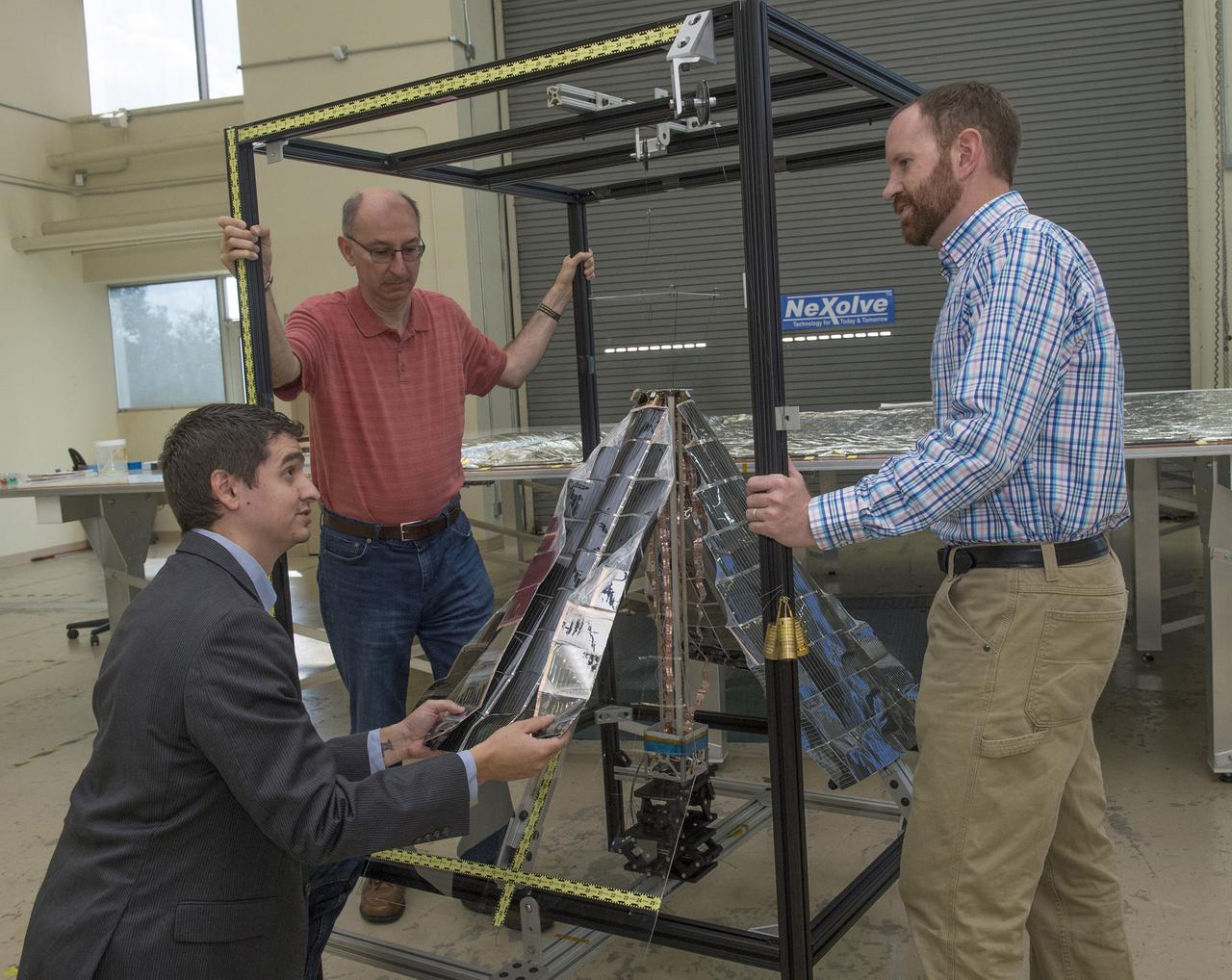
JOHN CARR, CO-PRINCIPAL INVESTIGATOR FOR NASA'S LIGHTWEIGHT INTEGRATED SOLAR ARRAY AND TRANSCEIVER PROJECT, KNEELS TO SHOW HOW ONE OF THE THIN-FILM SIDES OR "PETALS" IN WHICH PHOTO-VOLTAIC CELLS ARE EMBEDDED, IS FOLDED AND STOWED BEFORE LAUNCH. LOOKING ON DURING A DEMONSTRATION AFTER TESTING AT NEXOLVE, ARE LES JOHNSON, LEFT, ALSO CO-PRINCIPAL INVESTIGATOR, AND DARREN BOYD, RIGHT, THE RADIO FREQUENCY LEAD FOR THE PROJECT.

iss072e595424 (Jan. 30, 2025) --- NASA astronaut and Expedition 72 Commander Suni Williams is attached to the Canadarm2 robotic arm's latching end effector while being maneuvered to her worksite 264 miles above the South Pacific Ocean. Williams removed and stowed a radio frequency group antenna assembly during the five-hour and 26-minute spacewalk outside the International Space Station.
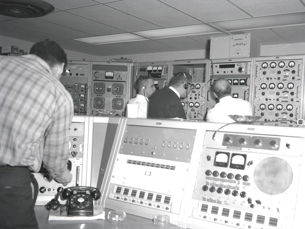
Activities at Green Mountain Tracking Station, Alabama, during lift-off of the Saturn I, SA-9 mission, showing the overall view of instrument panels used in tracking the Pegasus, meteoroid-detection satellite. The satellite was used to obtain data on frequency and penetration of the potentially hazardous micrometeoroids in low Earth orbits and to relay the information back to Earth.
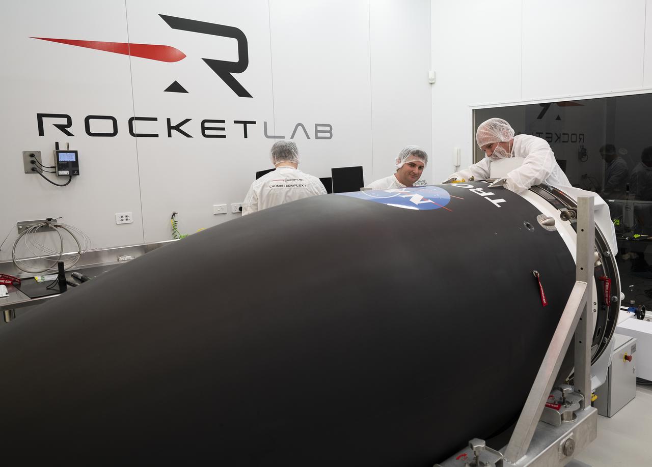
NASA’s Time-Resolved Observations of Precipitation structure and storm Intensity with a Constellation of Smallsats (TROPICS) CubeSats are encapsulated inside Rocket Lab’s Electron payload fairing in a processing facility near Launch Complex 1 in Mahia, New Zealand. TROPICS is scheduled to launch on Monday, May 1, at 1 a.m. New Zealand time from Launch Complex 1, Pad B. TROPICS will provide data on temperature, precipitation, water vapor, and clouds by measuring microwave frequencies, providing insight into storm formation and intensification.
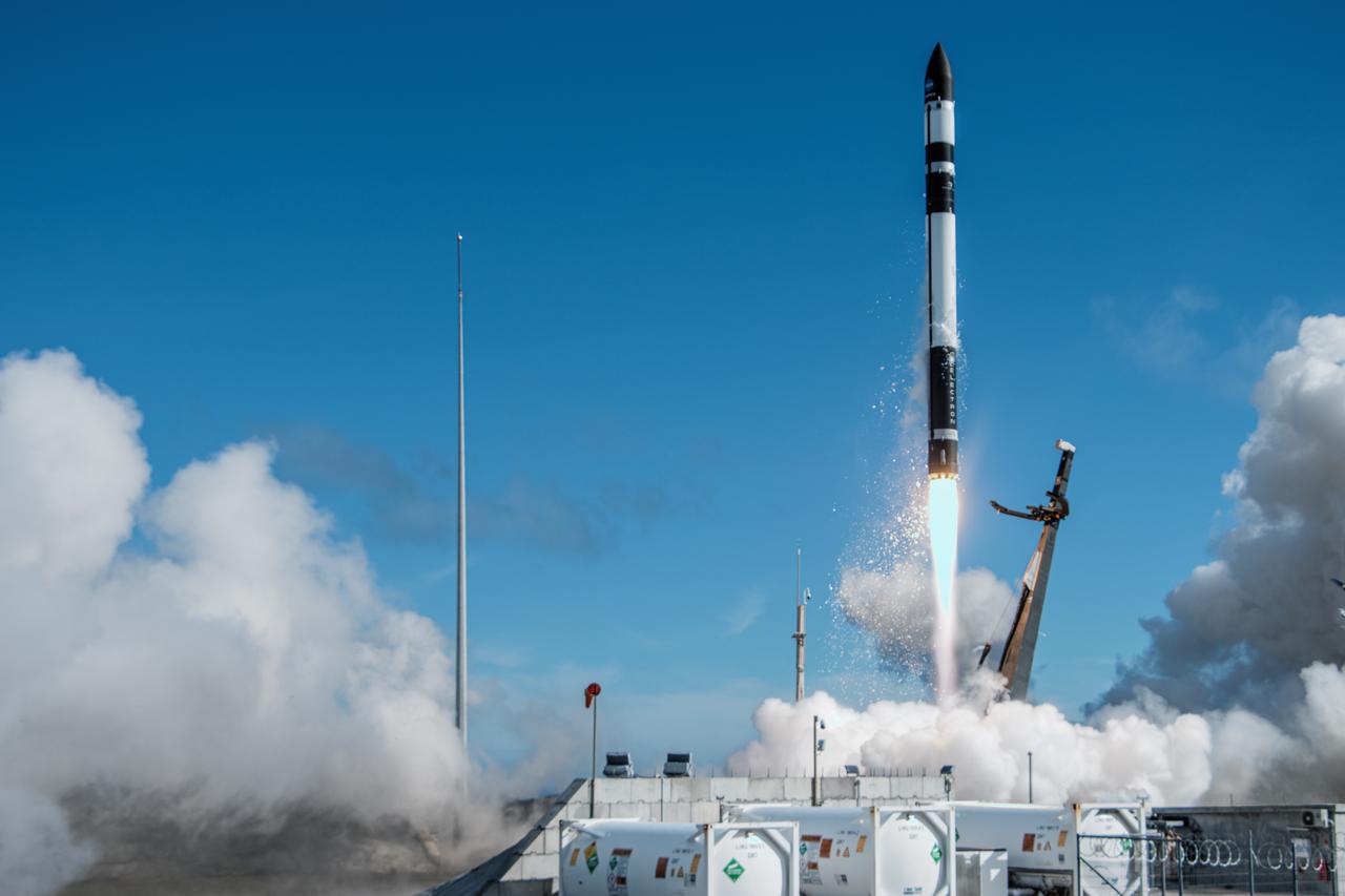
A Rocket Lab Electron rocket lifts off Launch Complex 1, Pad B, in Māhia, New Zealand on May 8 at 1 p.m. New Zealand time (May 7 at 9 p.m. EDT), carrying two NASA CubeSats designed to study tropical cyclones, including hurricanes and typhoons. NASA’s Time-Resolved Observations of Precipitation structure and storm Intensity with a Constellation of Smallsats (TROPICS) CubeSats will provide data on temperature, precipitation, water vapor, and clouds by measuring microwave frequencies, providing insight into storm formation and intensification.

iss072e595426 (Jan. 30, 2025) --- NASA astronaut and Expedition 72 Commander Suni Williams is attached to the Canadarm2 robotic arm's latching end effector while being maneuvered to her worksite 264 miles above the South Pacific Ocean. Williams removed and stowed a radio frequency group antenna assembly during the five-hour and 26-minute spacewalk outside the International Space Station.
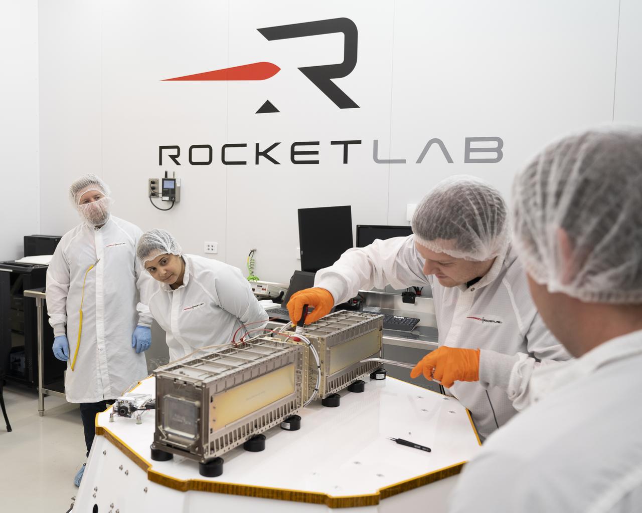
Technicians prepare NASA’s Time-Resolved Observations of Precipitation structure and storm Intensity with a Constellation of Smallsats (TROPICS) CubeSats for encapsulation in Rocket Lab’s Electron payload fairing in a processing facility near Launch Complex 1 in Mahia, New Zealand. TROPICS is scheduled to launch on Monday, May 1, at 1 a.m. New Zealand time from Launch Complex 1, Pad B. TROPICS will provide data on temperature, precipitation, water vapor, and clouds by measuring microwave frequencies, providing insight into storm formation and intensification.
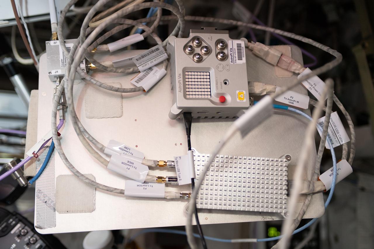
iss056e136189 (8/13/2020) --- A view of the Marconissta setup connected to the Amateur Radio on International Space Station (ARISS) antennas in the Columbus Module aboard the International Space Station (ISS). MarconISSta is a radio spectrum analyzer payload launched to ISS. MarconISSta monitors parts of the radio frequency spectrum in VHF, UHF, L, and S band in order to analyze current use and availability of bands for satellite communication.
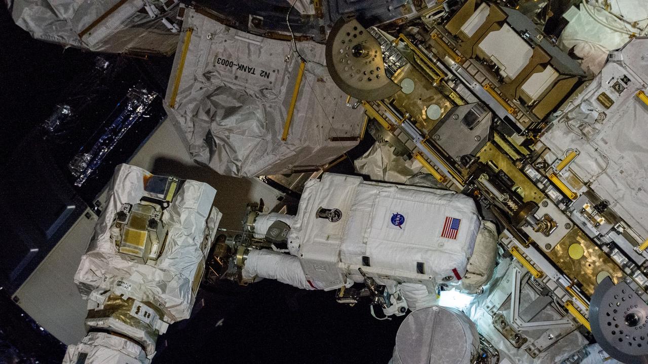
iss072e574847 (Jan. 30, 2025) --- NASA astronaut and Expedition 72 Commander Suni Williams works outside the International Space Station during a five-hour and 26-minute spacewalk to remove and stow a radio frequency group antenna assembly. In the left foreground, is the latching end effector of the Canadarm2 robotic arm. The orbital outpost was soaring 267 miles above New Zealand at the time of this photograph.
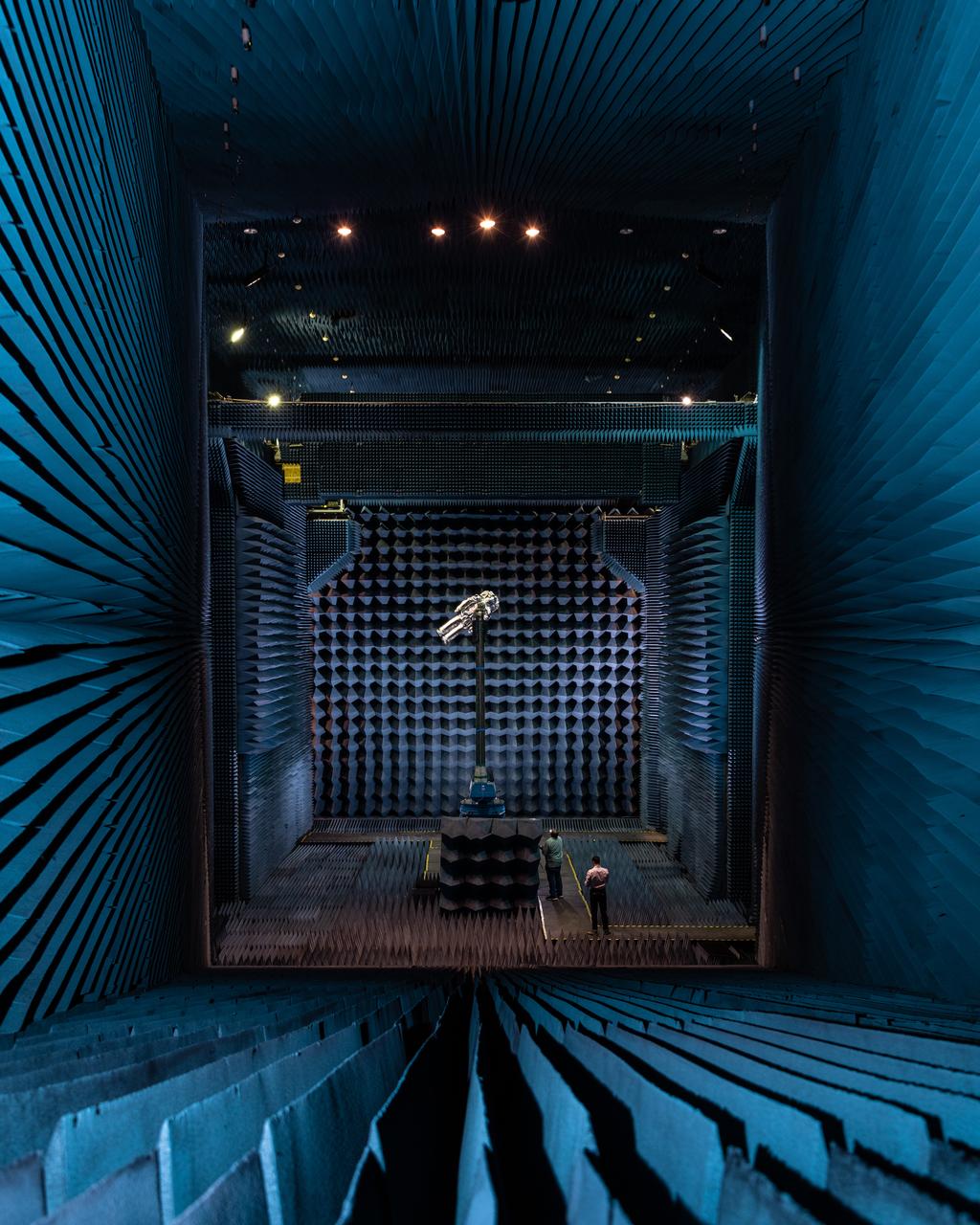
xEMU Antenna testing being performed in the B14 Anechoic Chamber to inspect MLI keep out zones for the antennas. The xEMU Test article is named xGUS, the successor to the EMU Test Article also named GUS (named after Gus Grissom and his iconic silver spacesuit). Image taken from where "horn" is located that sends out radio frequency signals for test. Photographer: Norah Moran – Johnson Space Center
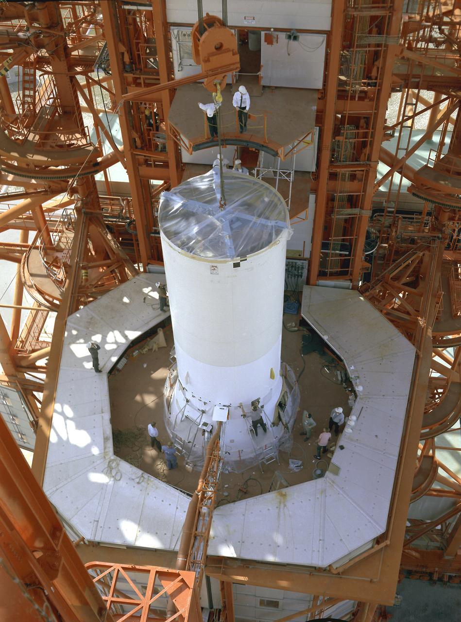
Pegasus-1, meteoroid detection satellite, installed on Saturn I (SA-9 mission) S-IV stage, January 13, 1965. The satellite was used to obtain data on frequency and penetration of the potentially hazardous micrometeoroids in low Earth orbits and to relay the information back to Earth. SA-9 was launched on February 16, 1965 and the Pegasus-1 satellite was the first operational payload for Saturn I.
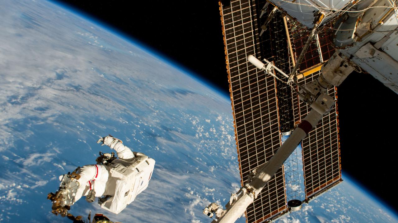
iss072e574907 (Jan. 30, 2025) --- NASA astronaut and Expedition 72 Commander Suni Williams is attached to the Canadarm2 robotic arm's latching end effector while being maneuvered to her worksite 264 miles above the South Pacific Ocean. Williams removed and stowed a radio frequency group antenna assembly during the five-hour and 26-minute spacewalk outside the International Space Station.
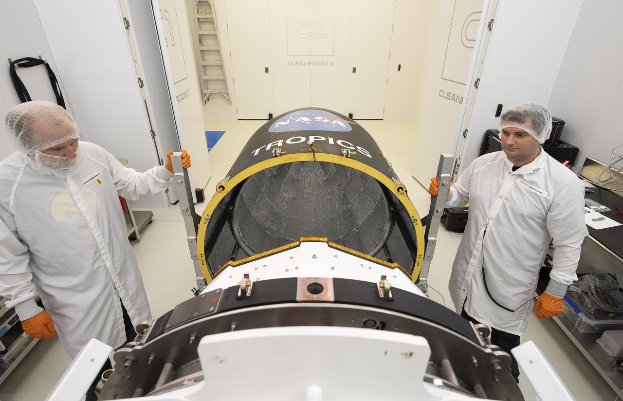
Technicians place NASA’s Time-Resolved Observations of Precipitation structure and storm Intensity with a Constellation of Smallsats (TROPICS) CubeSats in Rocket Lab’s Electron payload fairing in a processing facility near Launch Complex 1 in Mahia, New Zealand. TROPICS is scheduled to launch on Monday, May 1, at 1 a.m. New Zealand time from Launch Complex 1, Pad B. TROPICS will provide data on temperature, precipitation, water vapor, and clouds by measuring microwave frequencies, providing insight into storm formation and intensification.
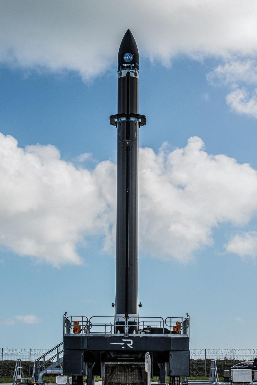
Rocket Lab’s Electron rocket is vertical on the pad at Launch Complex 1 in Mahia, New Zealand. NASA’s Time-Resolved Observations of Precipitation structure and storm Intensity with a Constellation of Smallsats (TROPICS) CubeSats are secured in the payload fairing atop the rocket. TROPICS is scheduled to launch on Monday, May 1, at 1 a.m. New Zealand time from Launch Complex 1, Pad B. TROPICS will provide data on temperature, precipitation, water vapor, and clouds by measuring microwave frequencies, providing insight into storm formation and intensification.

iss072e595491 (Jan. 30, 2025) --- NASA astronaut and Expedition 72 Commander Suni Williams is attached to the Canadarm2 robotic arm's latching end effector while being maneuvered to her worksite 264 miles above the South Pacific Ocean. Williams removed and stowed a radio frequency group antenna assembly during the five-hour and 26-minute spacewalk outside the International Space Station.
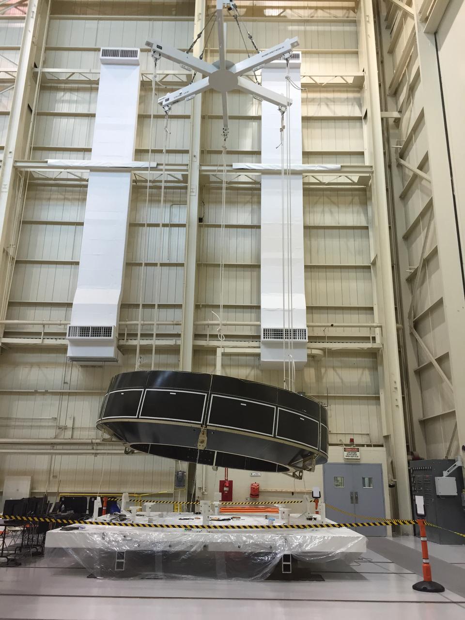
Engineers at the NASA’s Plum Brook Station in Sandusky, Ohio, begin the first of a series of modal tests on an Orion service module structural test article provided by the European Space Agency on July 20, 2015. This test vibrates spacecraft structural elements at various frequencies to simulate how launch vibrations and acoustics will affect the vehicle. Part of Batch image transfer from Flickr.
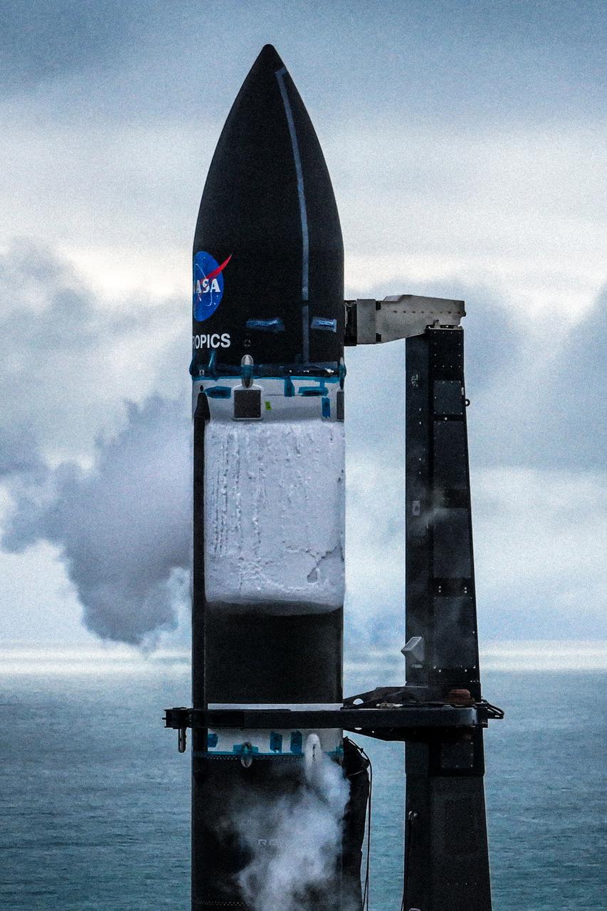
A wet dress rehearsal is underway for Rocket Lab’s Electron rocket at Launch Complex 1 in Mahia, New Zealand on April 28, 2023. NASA’s Time-Resolved Observations of Precipitation structure and storm Intensity with a Constellation of Smallsats (TROPICS) CubeSats are secured in the payload fairing atop the rocket. TROPICS is scheduled to launch from Launch Complex 1, Pad B. TROPICS will provide data on temperature, precipitation, water vapor, and clouds by measuring microwave frequencies, providing insight into storm formation and intensification.
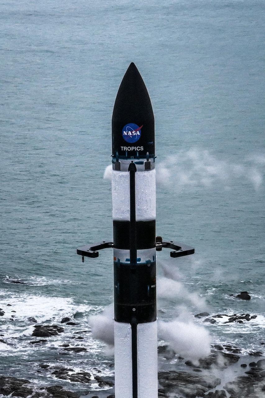
A wet dress rehearsal is underway for Rocket Lab’s Electron rocket at Launch Complex 1 in Mahia, New Zealand on April 28, 2023. NASA’s Time-Resolved Observations of Precipitation structure and storm Intensity with a Constellation of Smallsats (TROPICS) CubeSats are secured in the payload fairing atop the rocket. TROPICS is scheduled to launch from Launch Complex 1, Pad B. TROPICS will provide data on temperature, precipitation, water vapor, and clouds by measuring microwave frequencies, providing insight into storm formation and intensification.
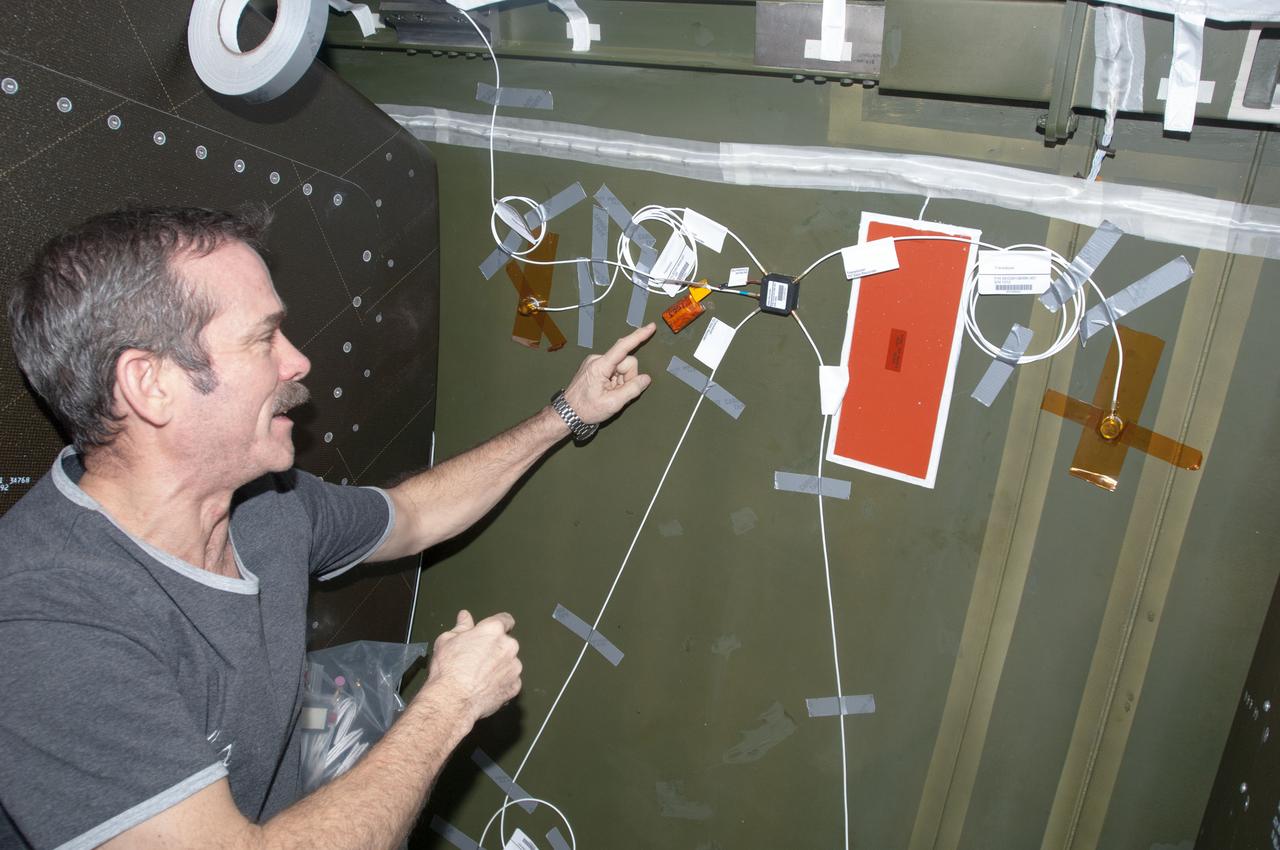
ISS034-E-038211 (1 Feb. 2013) --- Canadian Space Agency astronaut Chris Hadfield, Expedition 34 flight engineer, installs Ultra-Sonic Background Noise Tests (UBNT) sensors behind a rack in the Destiny laboratory, using the International Space Station (ISS) as Testbed for Analog Research (ISTAR) procedures. These sensors detect high frequency noise levels generated by ISS hardware and equipment operating within Destiny.
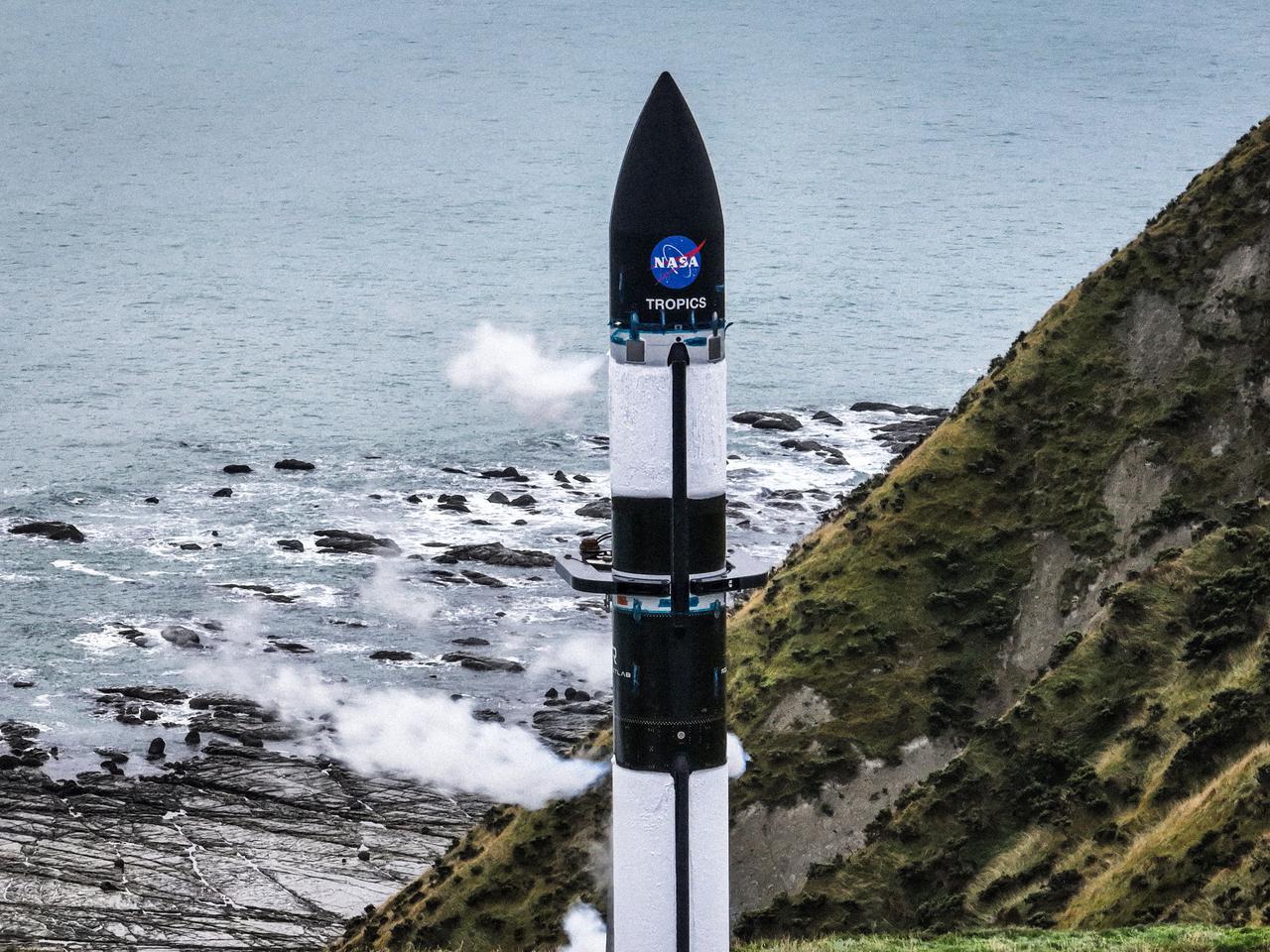
A wet dress rehearsal is underway for Rocket Lab’s Electron rocket at Launch Complex 1 in Mahia, New Zealand on April 28, 2023. NASA’s Time-Resolved Observations of Precipitation structure and storm Intensity with a Constellation of Smallsats (TROPICS) CubeSats are secured in the payload fairing atop the rocket. TROPICS is scheduled to launch from Launch Complex 1, Pad B. TROPICS will provide data on temperature, precipitation, water vapor, and clouds by measuring microwave frequencies, providing insight into storm formation and intensification.