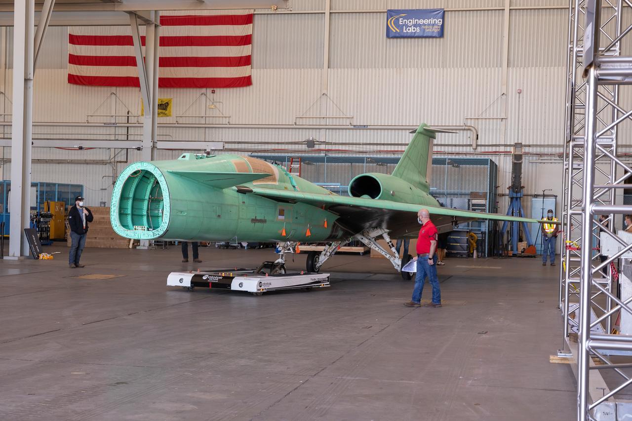
The X-59 is transported to the fuel barn at Lockheed Martin in Fort Worth, Texas to undergo fuel tank calibration tests. During this phase, the X-59’s gas tanks were filled and fuel-remaining sensors inside the aircraft were checked.
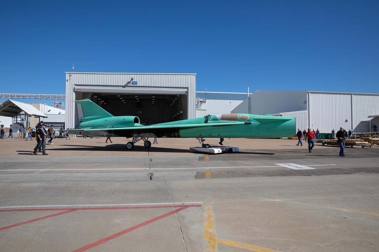
The X-59 is transported to the fuel barn at Lockheed Martin in Fort Worth, Texas to undergo fuel tank calibration tests. During this phase, the X-59’s gas tanks were filled and fuel-remaining sensors inside the aircraft were checked.
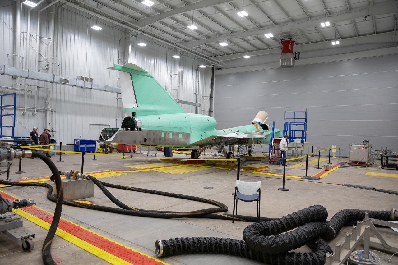
The X-59 sits in the fuel barn at Lockheed Martin in Fort Worth, Texas. While in the fuel barn, the X-59 underwent fuel tank calibration tests. During this phase, the X-59’s gas tanks were filled and fuel-remaining sensors inside the aircraft were checked.
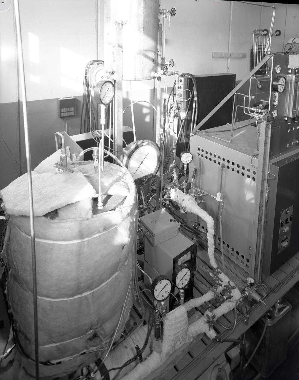
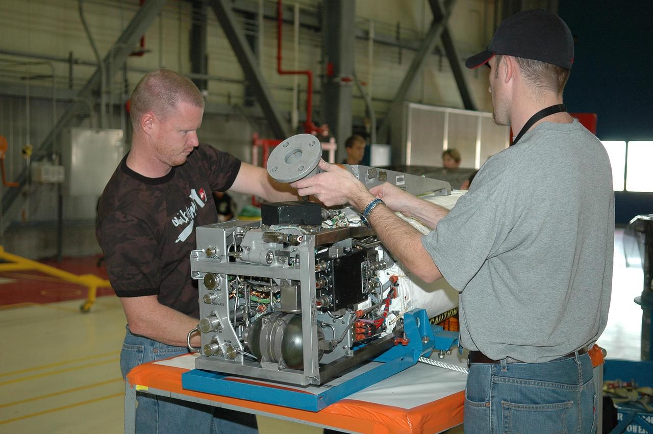
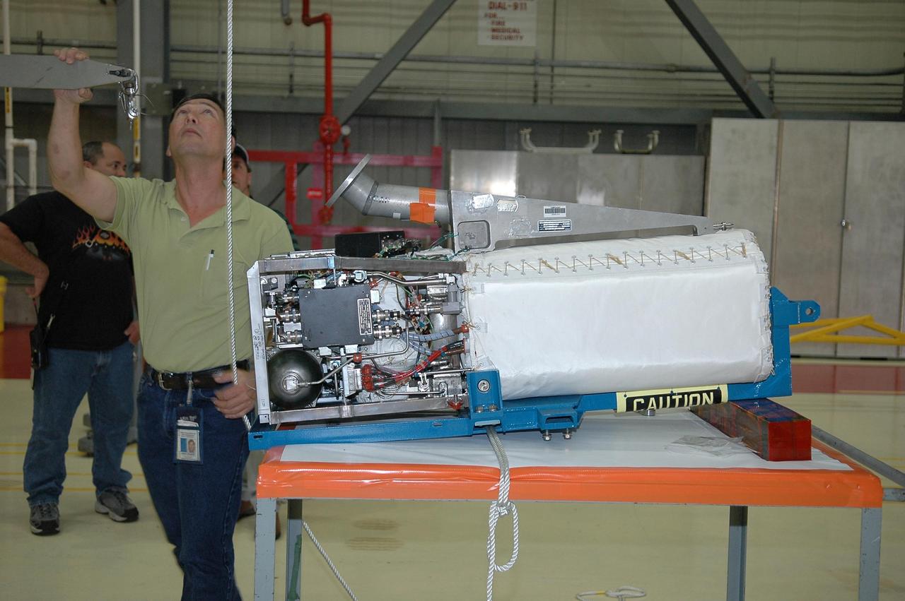
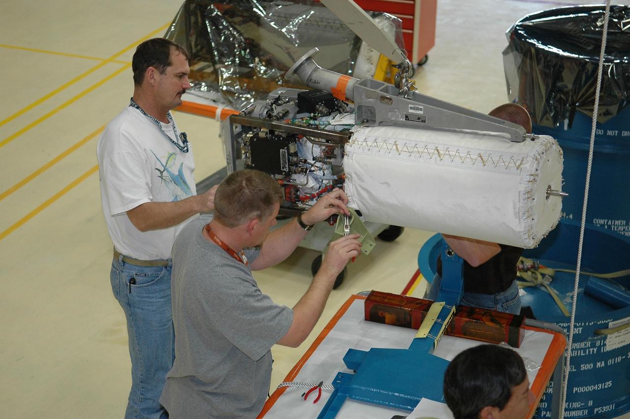
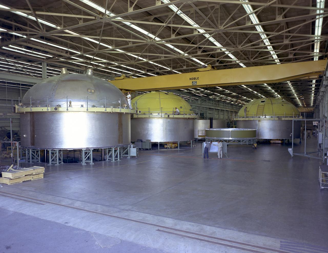
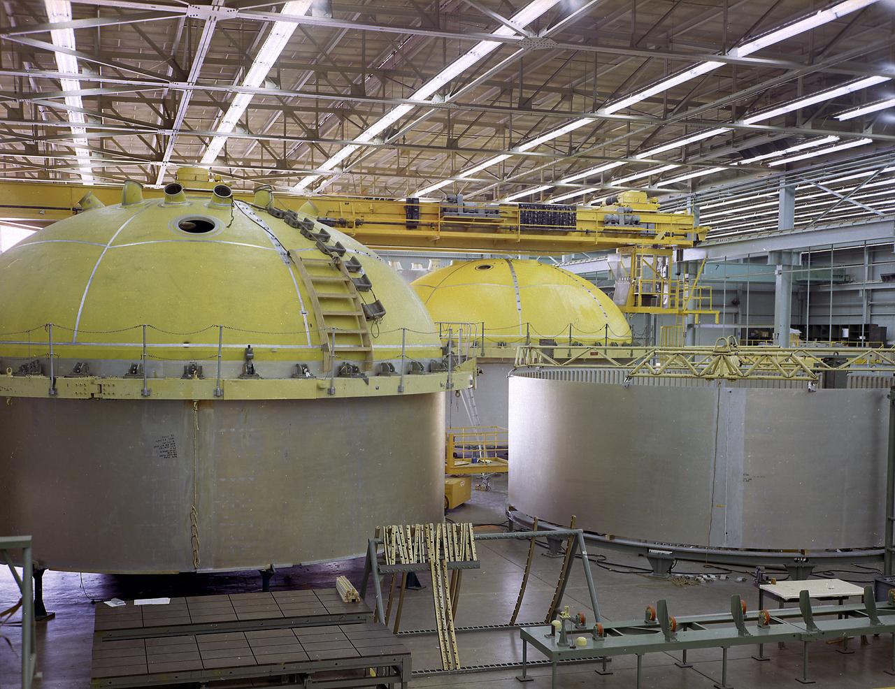
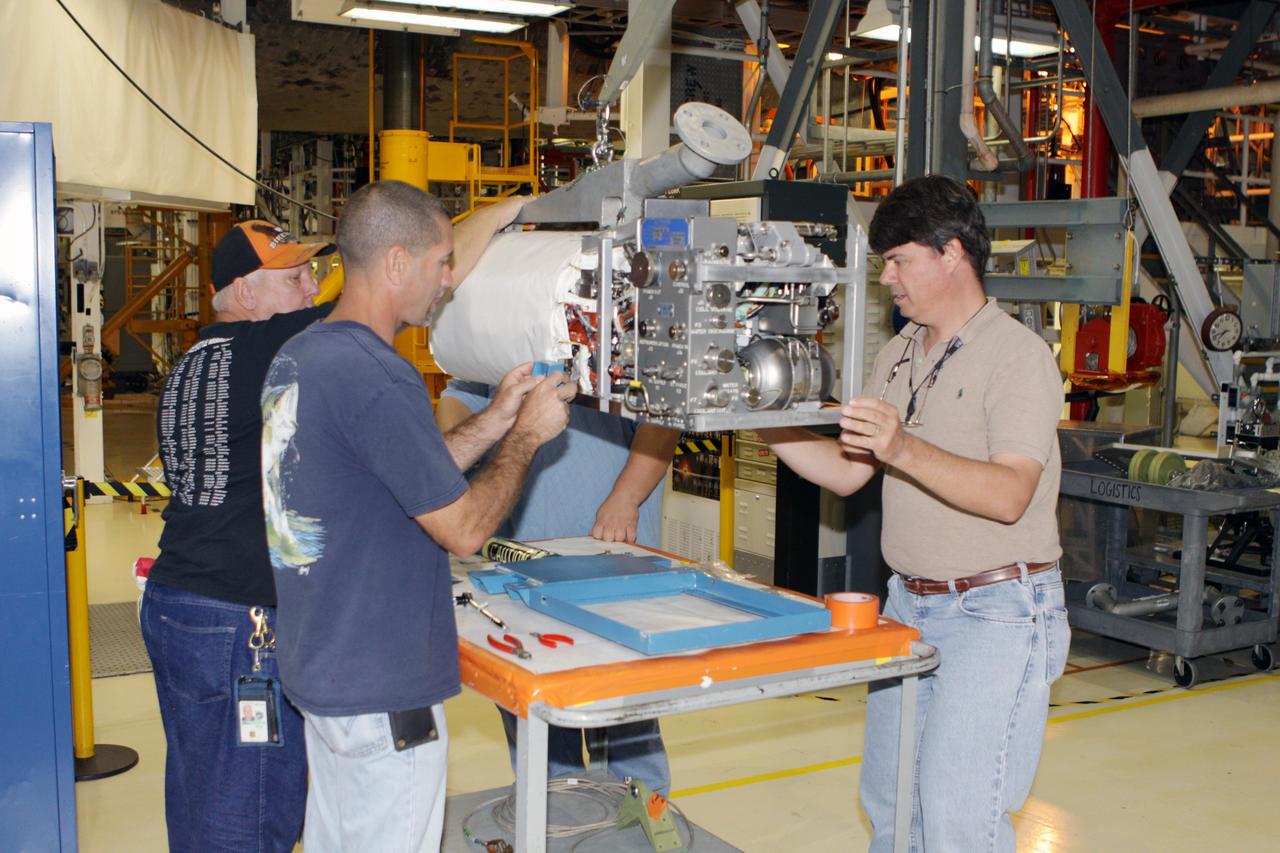
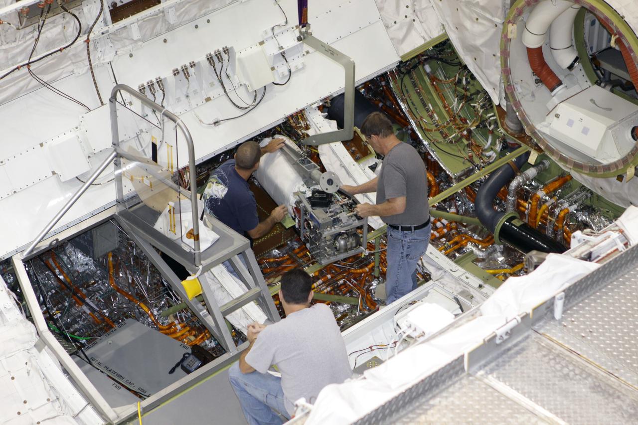
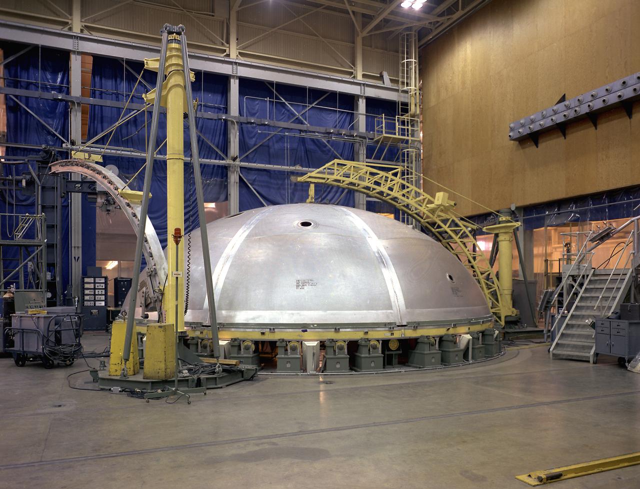
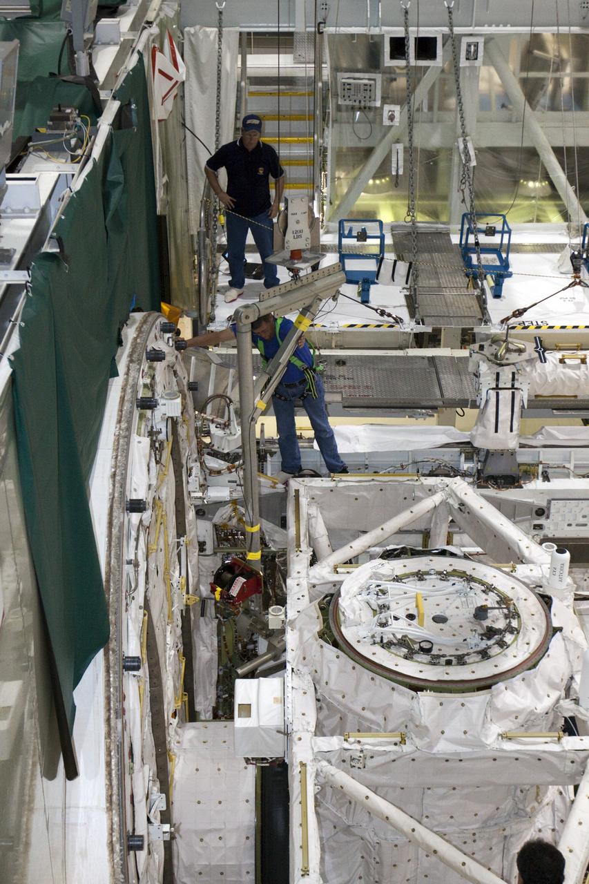
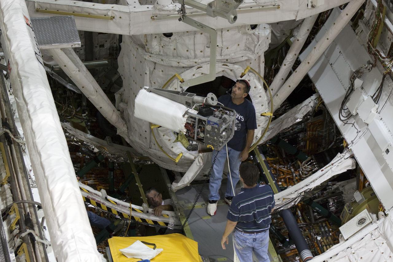
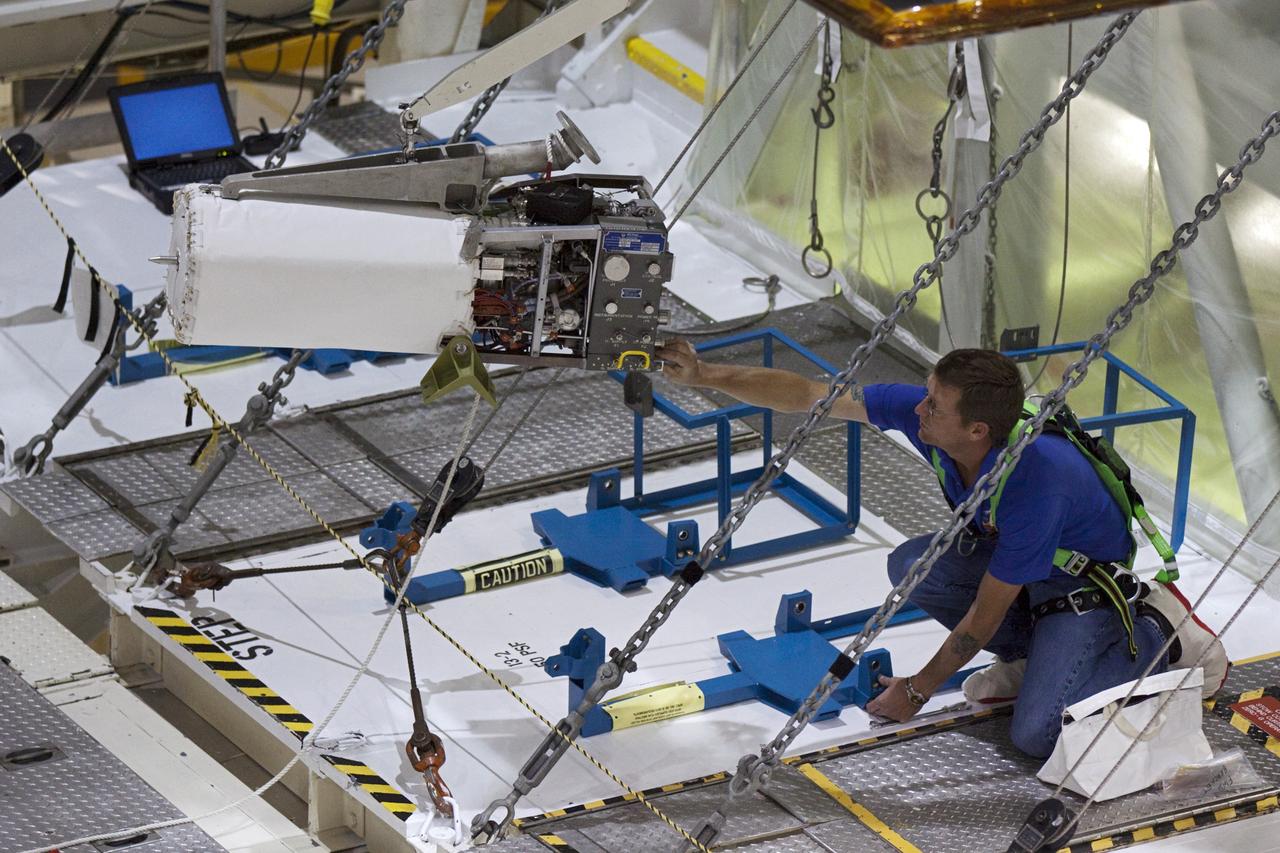
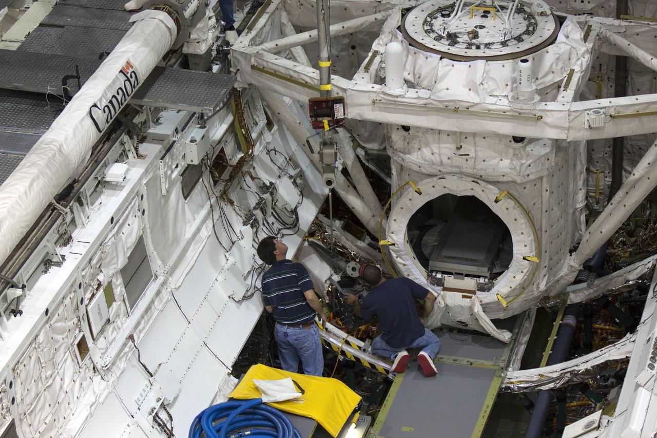
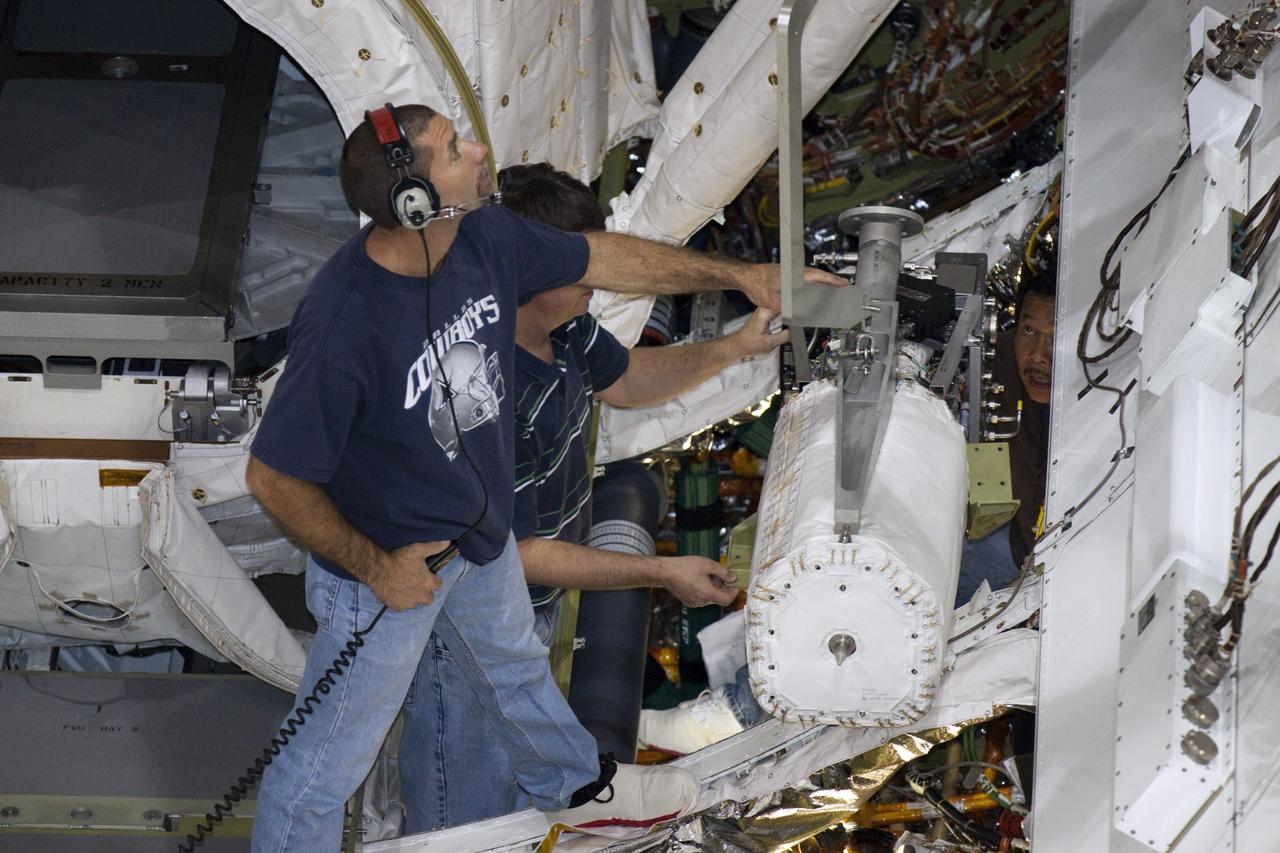
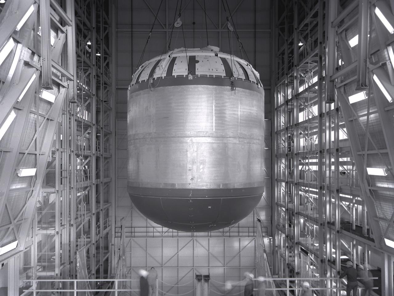
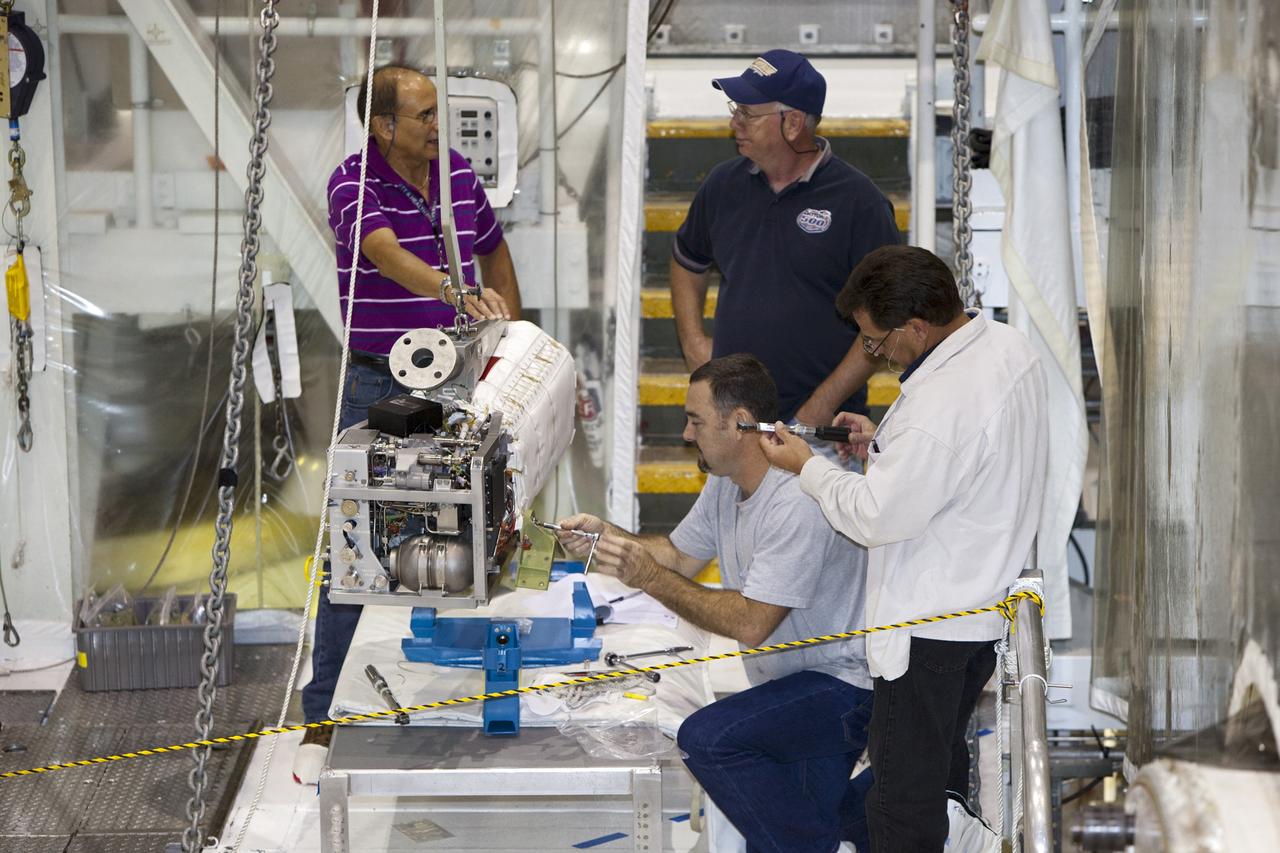
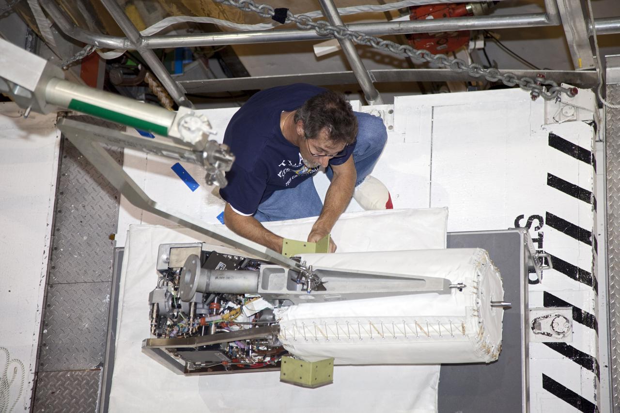
FUEL CELL CONDENSER FOR THE APOLLO SYSTEM TEST RIG
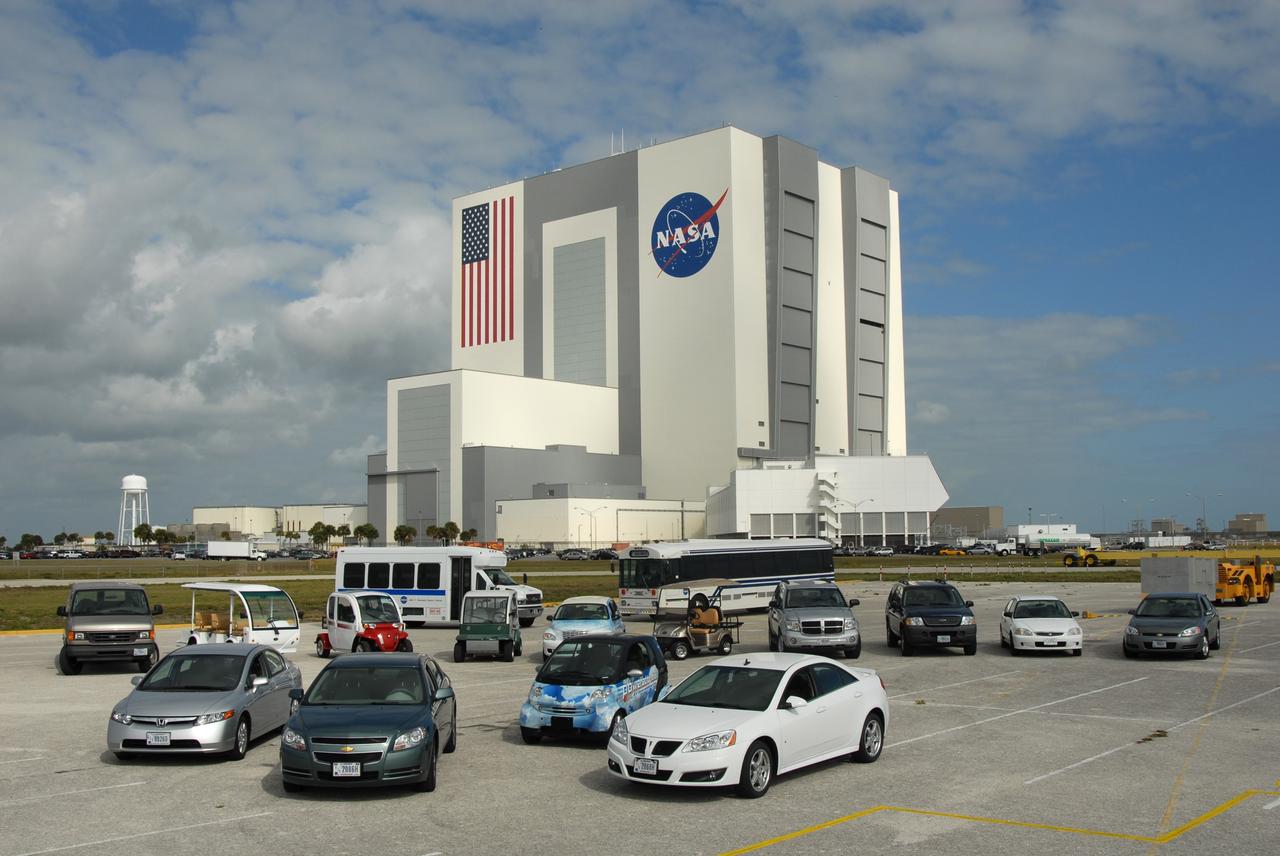
CAPE CANAVERAL, Fla. –– A variety of alternative fuel vehicles are driven around NASA's Kennedy Space Center in Florida in an effort to reduce gasoline consumption and conserve energy. These include compressed natural gas, bi-fuel, diesel fuel and flex fuel vehicles. Here they are on display at the NASA News Center. In the background is the Vehicle Assembly Building. Photo credit: NASA/Jim Grossmann
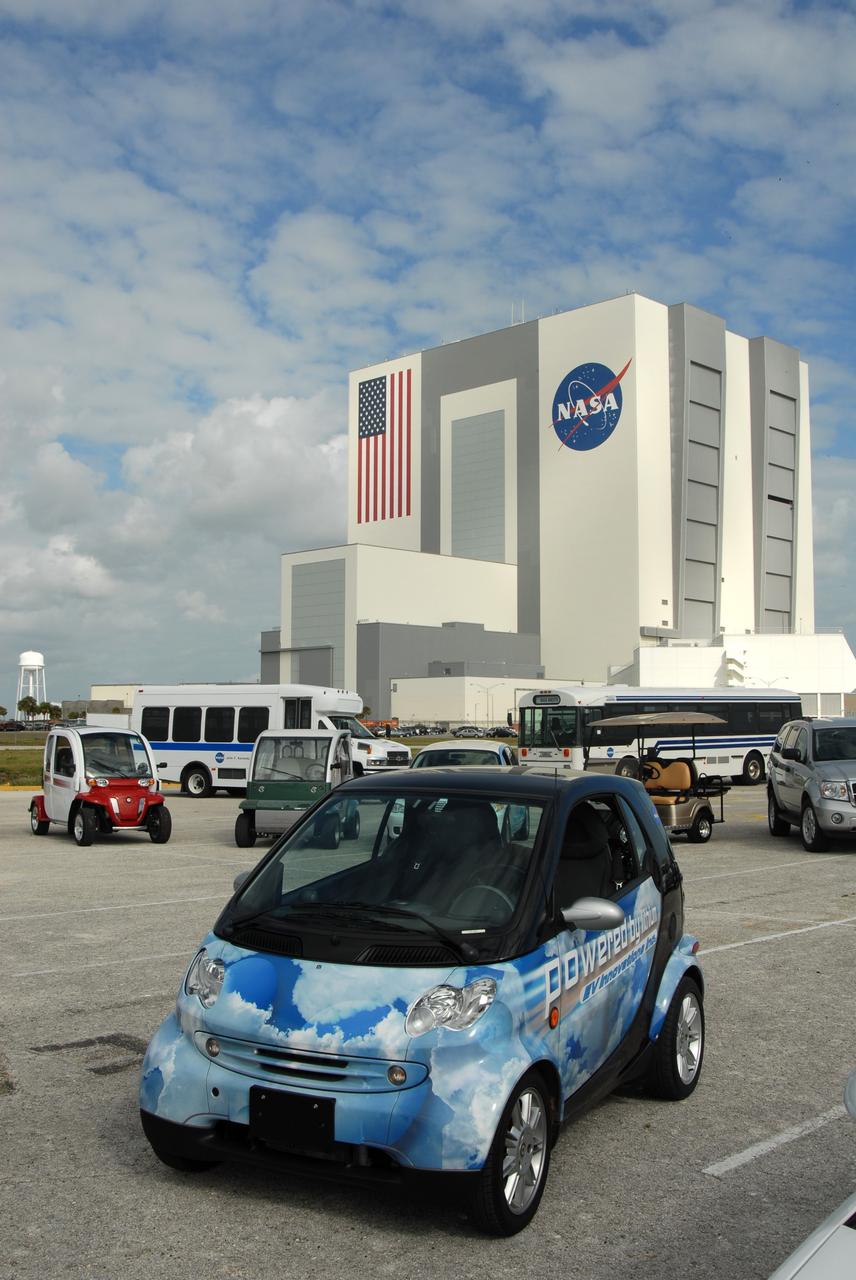
CAPE CANAVERAL, Fla. –– On display at NASA's Kennedy Space Center in Florida is one of the variety of alternative fuel vehicles driven around the center in an effort to reduce gasoline consumption and conserve energy. This car is a LiV Dash, a lithium vehicle Smart Car that uses lithium batteries. The other vehicles include compressed natural gas, bi-fuel, diesel fuel and flex fuel vehicles. Photo credit: NASA/Jim Grossmann
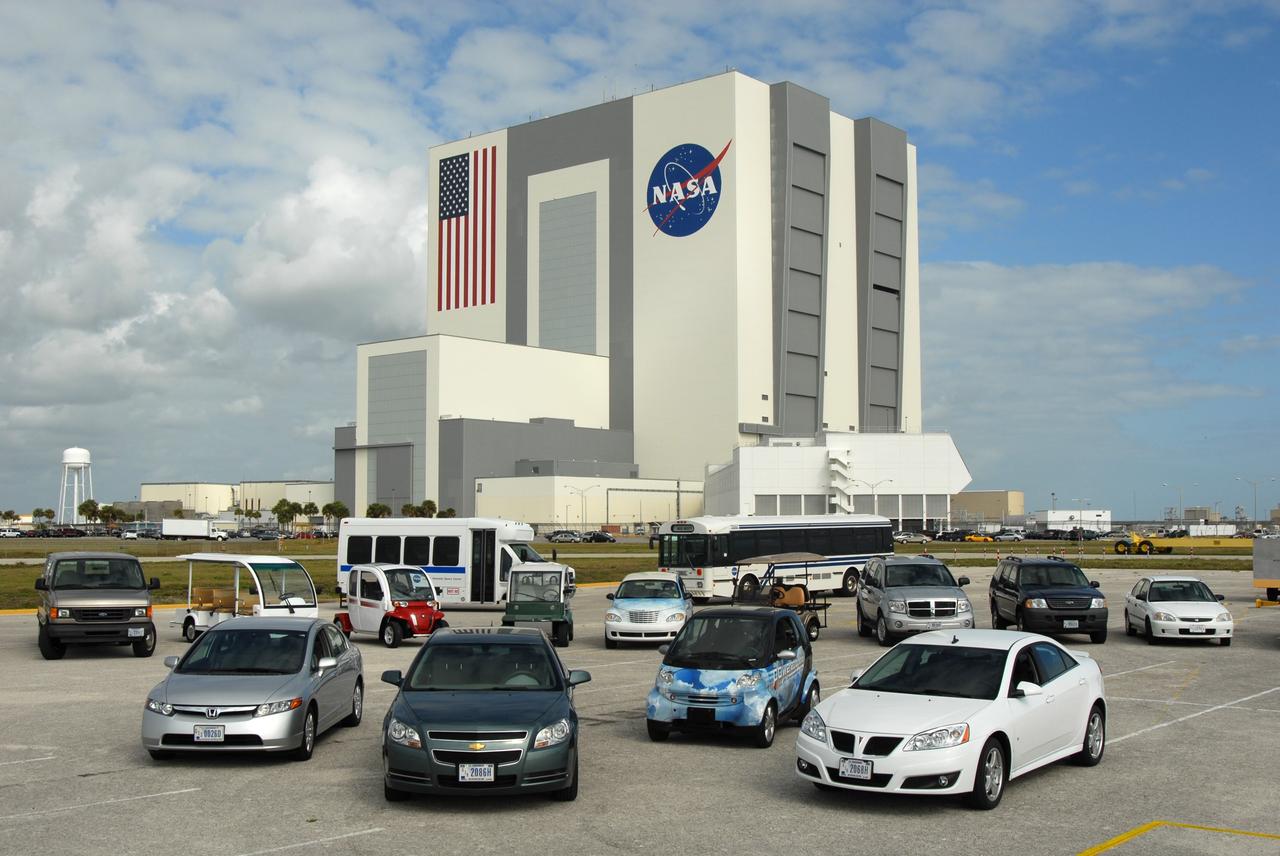
CAPE CANAVERAL, Fla. –– A variety of alternative fuel vehicles are driven around NASA's Kennedy Space Center in Florida in an effort to reduce gasoline consumption and conserve energy. These include compressed natural gas, bi-fuel, diesel fuel and flex fuel vehicles. Here they are on display at the NASA News Center. In the background is the Vehicle Assembly Building. Photo credit: NASA/Jim Grossmann
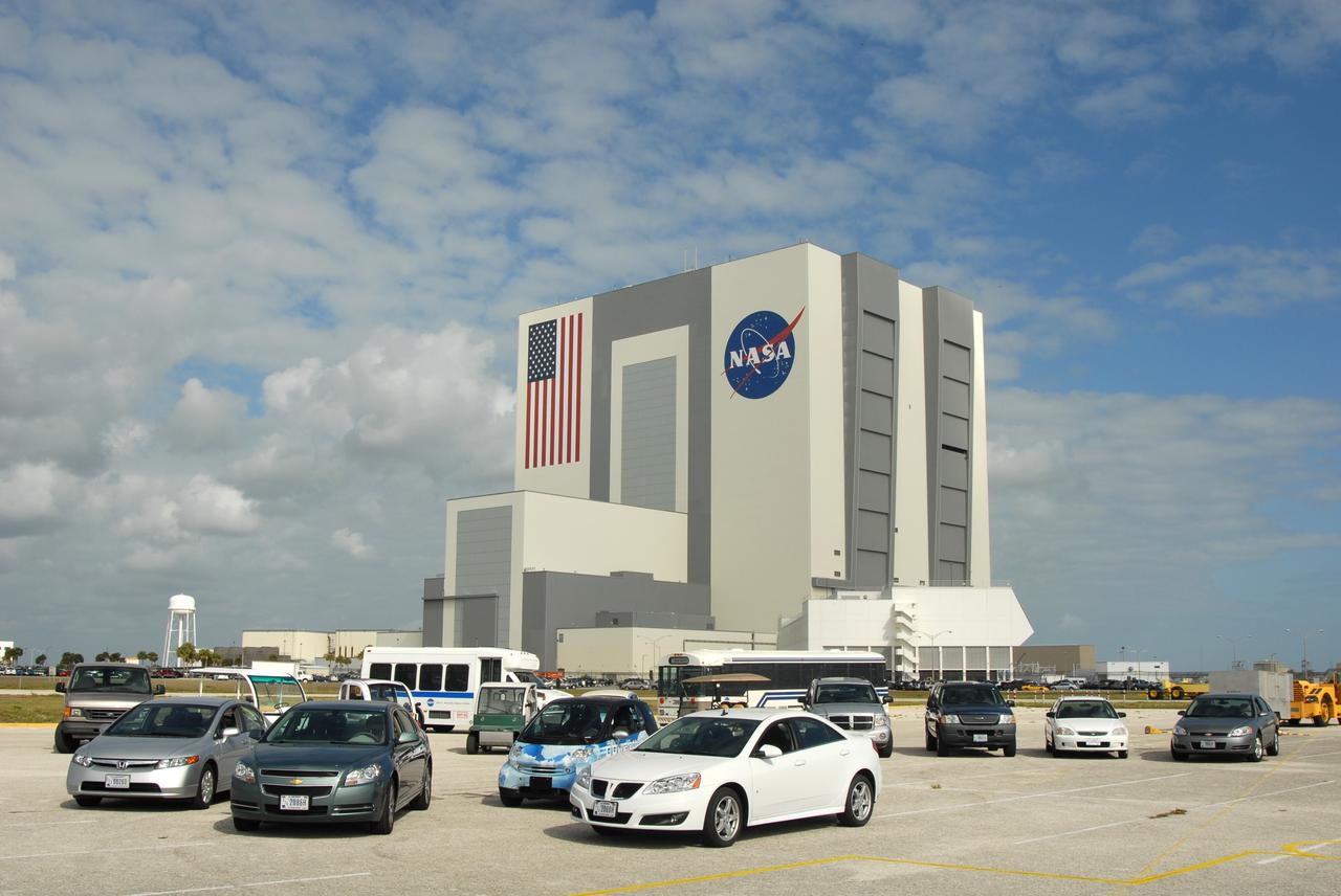
CAPE CANAVERAL, Fla. –– A variety of alternative fuel vehicles are driven around NASA's Kennedy Space Center in Florida in an effort to reduce gasoline consumption and conserve energy. These include compressed natural gas, bi-fuel, diesel fuel and flex fuel vehicles. Here they are on display at the NASA News Center. In the background is the Vehicle Assembly Building. Photo credit: NASA/Jim Grossmann

John C. Stennis Space Center, America's largest rocket engine test complex, and one of the country's leading consumers of liquid hydrogen, was the location Feb. 27 for a fuel stop of three Mercedes B-Class F-CELL vehicles. The B-Class F-CELL is an electric vehicle, which is powered by electricity produced on board the vehicle from hydrogen gas. The only emission by this unique vehicle is pure water vapor. Due to the limited number of existing hydrogen locations, Stennis Space Center provided a logical choice for a refueling location as the vehicle made its way across the United States as part of a worldwide tour.
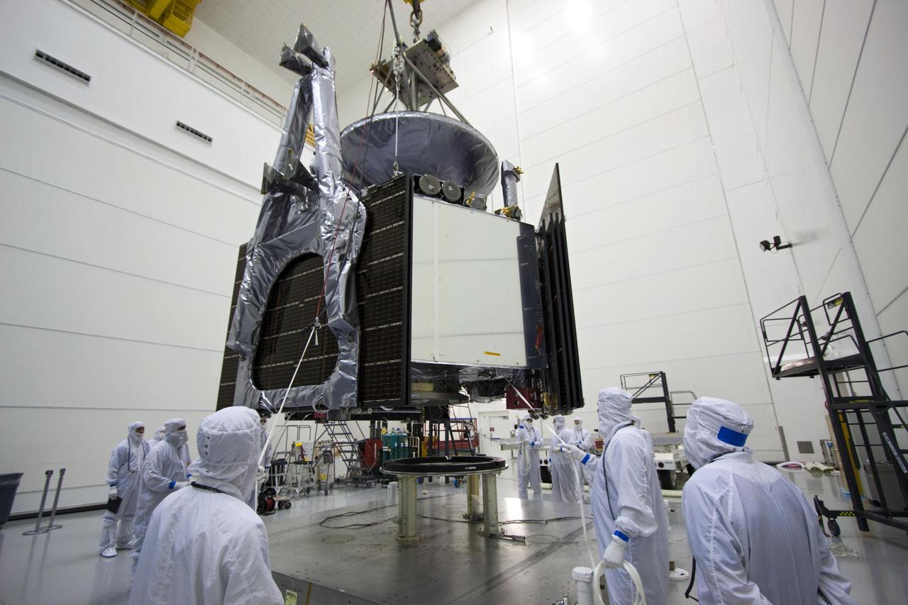
Technicians use an overhead crane to lower NASA Juno spacecraft onto a fueling stand where the spacecraft will be loaded with the propellant necessary for its mission to Jupiter.
jsc2024e021222 (3/21/2024) --- Solid Fuel Ignition and Extinction (SoFIE) insert supports the Growth and Extinction Limit (GEL) investigation test image taken in the Combustion Integrated Rack (CIR). This image was taken just prior to flame extinction while the green LED was flashing on. The LED allows the fuel surface to be seen during the burn, so that several important parameters can be evaluated, such as how far the flame is from the fuel and how much the fuel is heating up. The igniter wire appears in the camera view, but it is in the foreground and not near the flame. In the background on the left, an unburned acrylic sphere waits for its turn to be tested on another day.
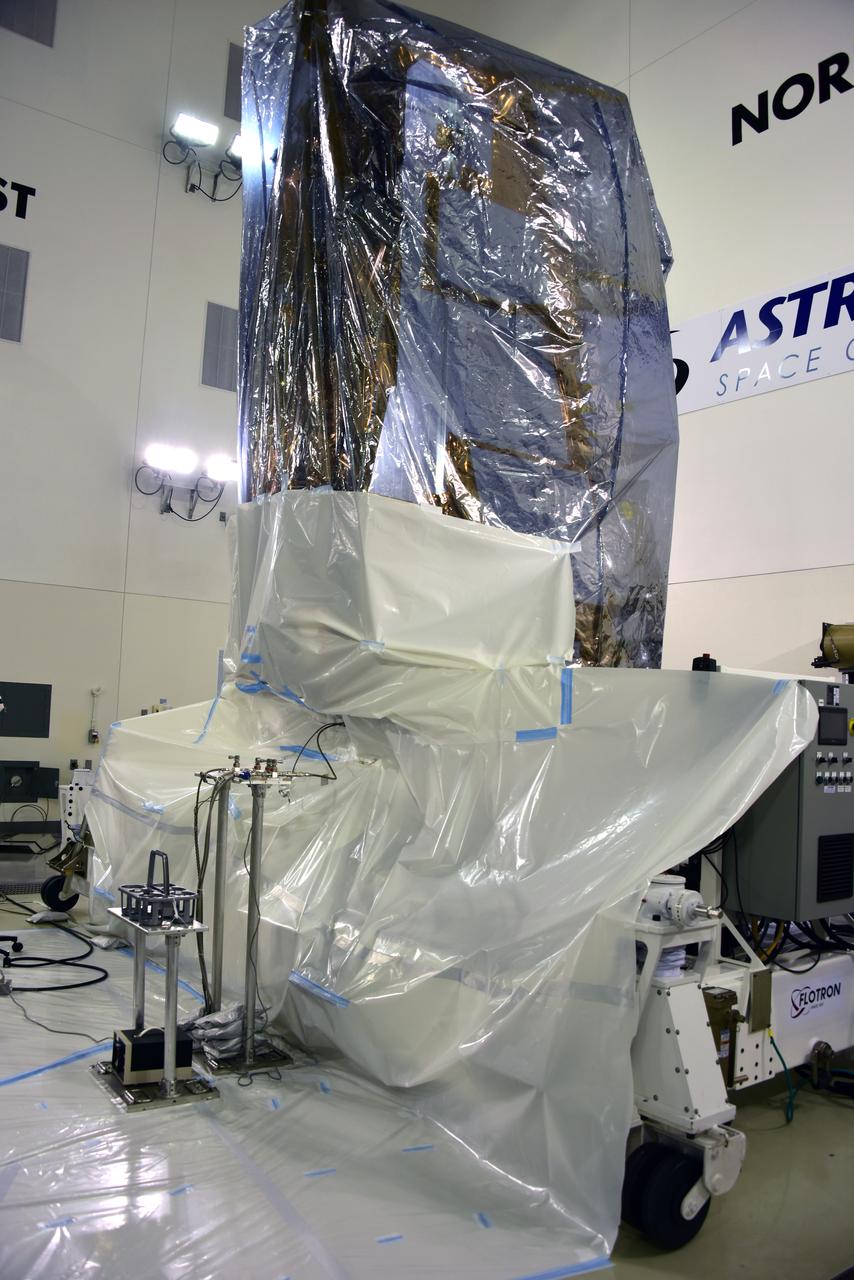
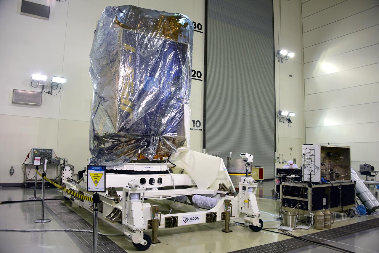
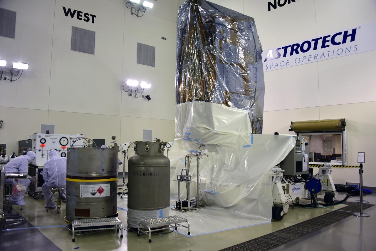
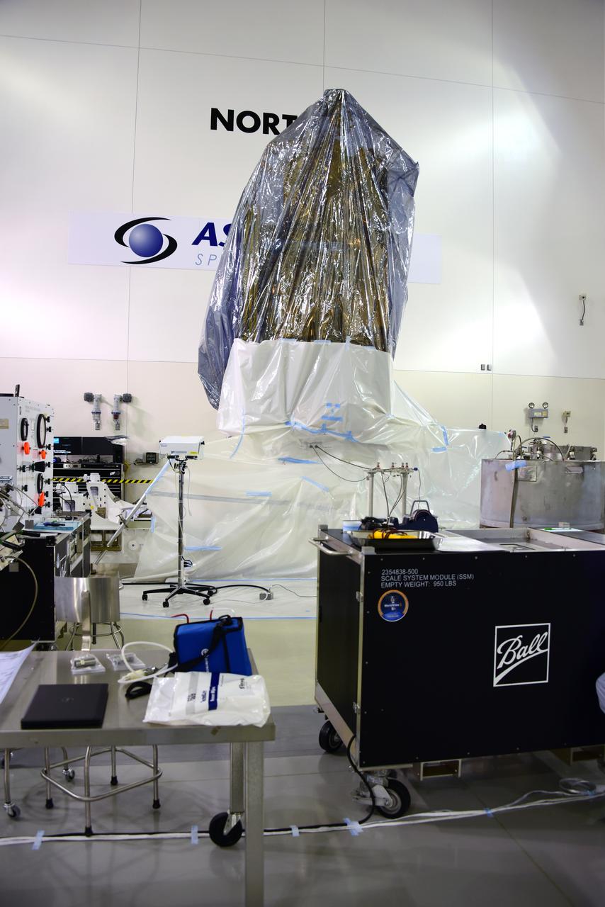
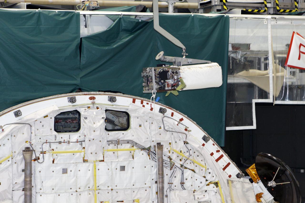
NOAA's Joint Polar Satellite System-1, or JPSS-1, remains wrapped in a protective covering after removal from its shipping container at the Astrotech Processing Facility at Vandenberg Air Force Base in California. The spacecraft is being prepared for its upcoming liftoff aboard a United Launch Alliance Delta II rocket from Vandenberg's Space Launch Complex-2W. JPSS-1 is the first in a series four next-generation environmental satellites in a collaborative program between NOAA and NASA.
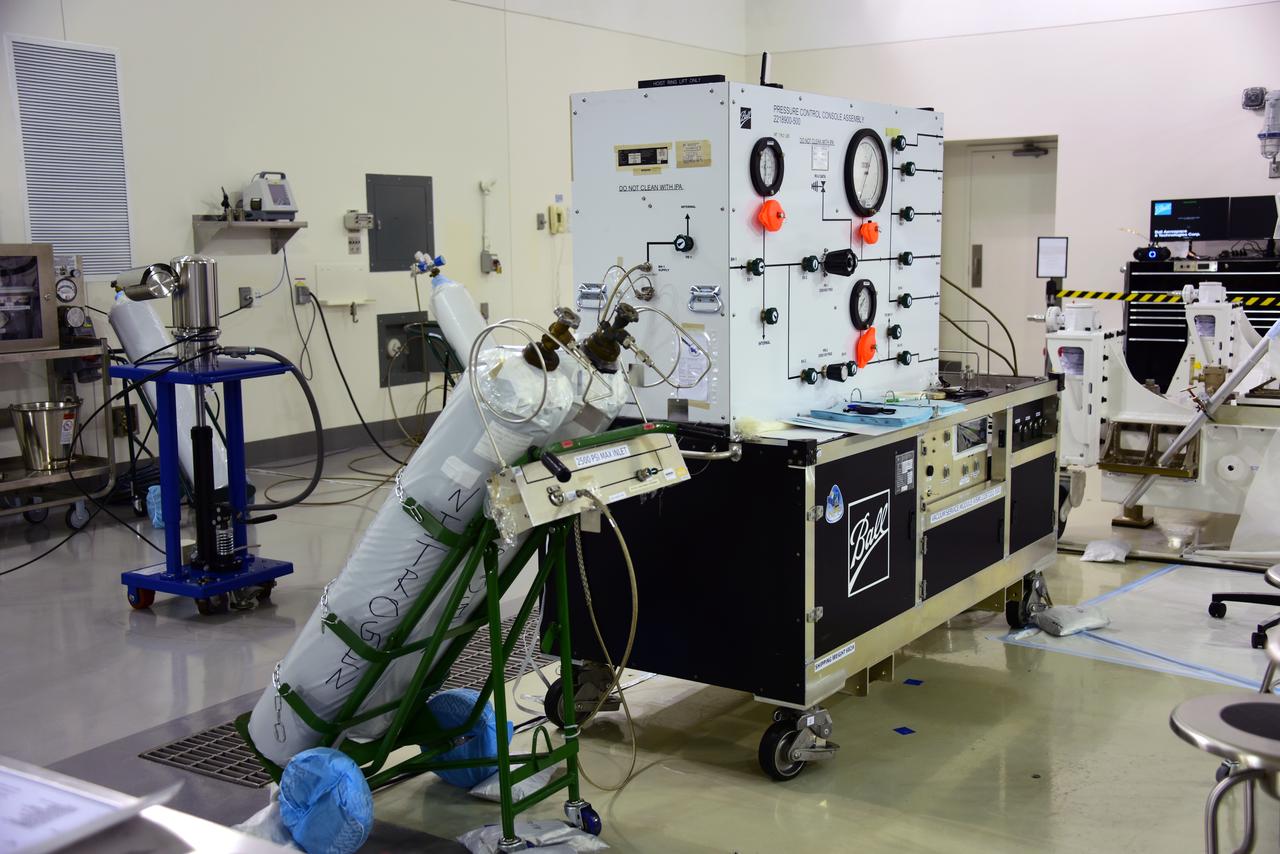
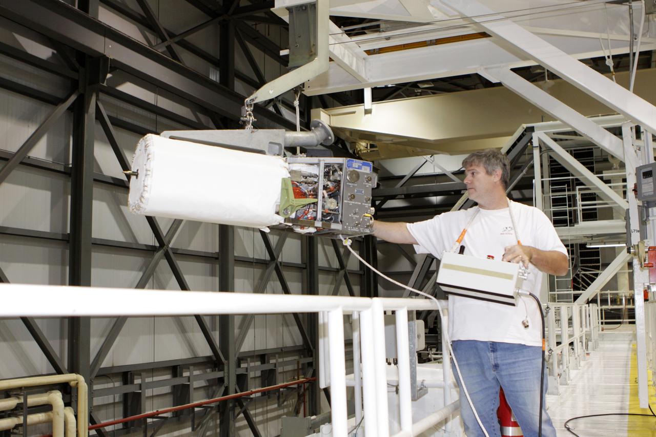
Equipment is set up for the processing of NOAA's Joint Polar Satellite System-1, or JPSS-1, inside the Astrotech Processing Facility at Vandenberg Air Force Base in California. The spacecraft is being prepared for its upcoming liftoff aboard a United Launch Alliance Delta II rocket from Vandenberg's Space Launch Complex-2W. JPSS-1 is the first in a series four next-generation environmental satellites in a collaborative program between NOAA and NASA.
NOAA's Joint Polar Satellite System-1, or JPSS-1, remains wrapped in a protective covering after removal from its shipping container at the Astrotech Processing Facility at Vandenberg Air Force Base in California. The spacecraft is being prepared for its upcoming liftoff aboard a United Launch Alliance Delta II rocket from Vandenberg's Space Launch Complex-2W. JPSS-1 is the first in a series four next-generation environmental satellites in a collaborative program between NOAA and NASA.
NOAA's Joint Polar Satellite System-1, or JPSS-1, remains wrapped in a protective covering after removal from its shipping container at the Astrotech Processing Facility at Vandenberg Air Force Base in California. The spacecraft is being prepared for its upcoming liftoff aboard a United Launch Alliance Delta II rocket from Vandenberg's Space Launch Complex-2W. JPSS-1 is the first in a series four next-generation environmental satellites in a collaborative program between NOAA and NASA.
Equipment is set up for the processing of NOAA's Joint Polar Satellite System-1, or JPSS-1, inside the Astrotech Processing Facility at Vandenberg Air Force Base in California. The spacecraft is being prepared for its upcoming liftoff aboard a United Launch Alliance Delta II rocket from Vandenberg's Space Launch Complex-2W. JPSS-1 is the first in a series four next-generation environmental satellites in a collaborative program between NOAA and NASA.
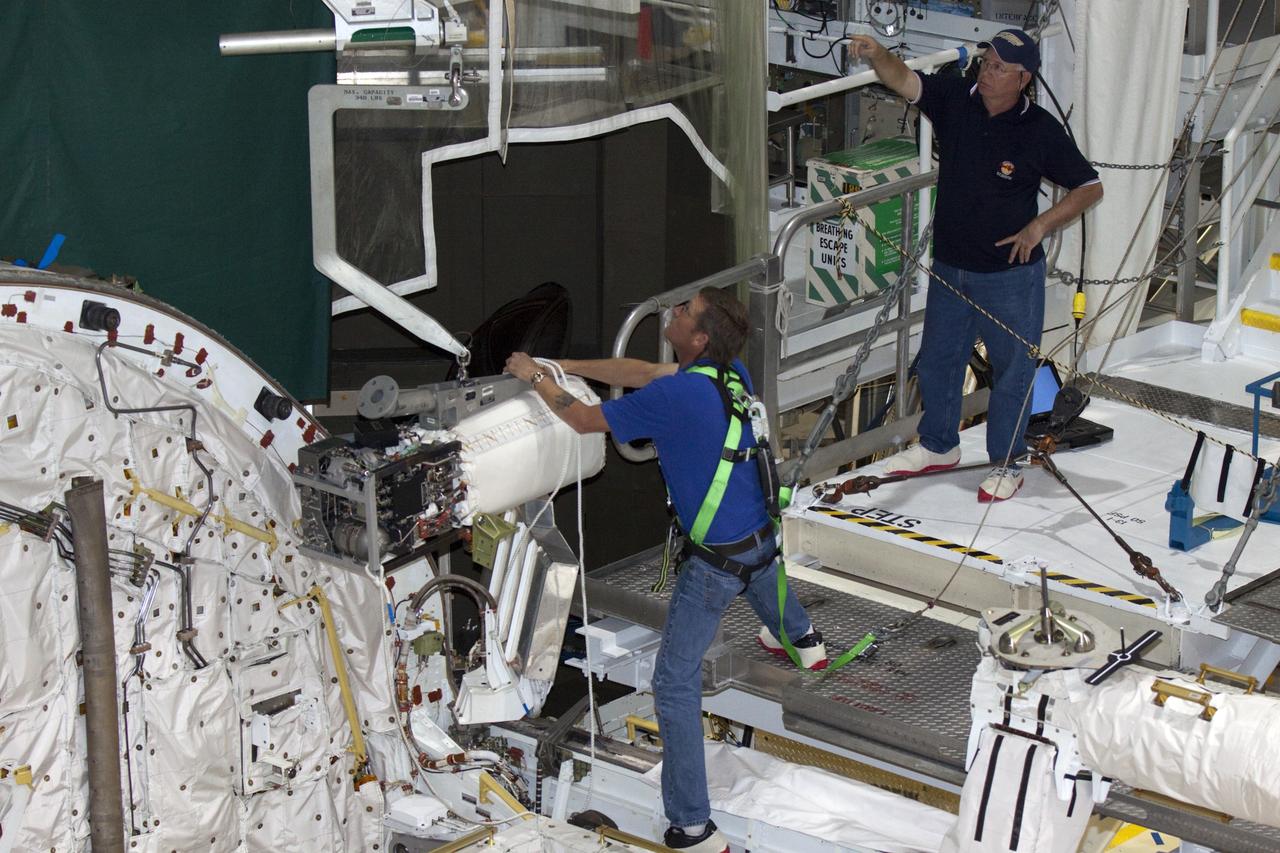
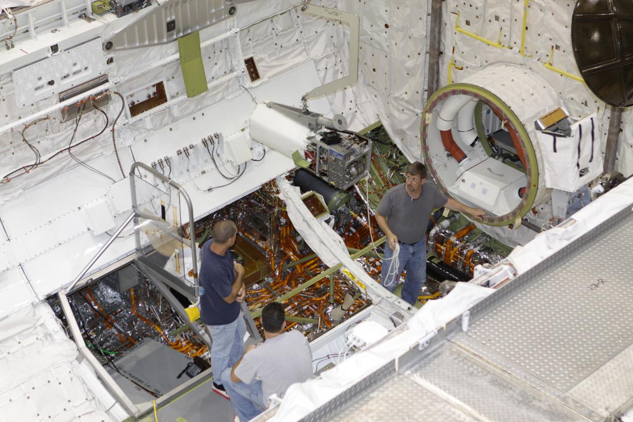
KENNEDY SPACE CENTER, FLA. - In NASA Kennedy Space Center’s Orbiter Processing Facility bay 3, a fuel cell removed from the orbiter Discovery is lowered toward a work stand. Fuel cells are located under the forward portion of the payload bay. They make power for the orbiter by mixing hydrogen and oxygen to produce electricity. Fuel cells also create potable water that is pumped into storage tanks for the crew to use in orbit. Discovery is the designated orbiter for the second return-to-flight mission, STS-121, scheduled for launch in May. Photo credit: NASA/Kim Shiflett

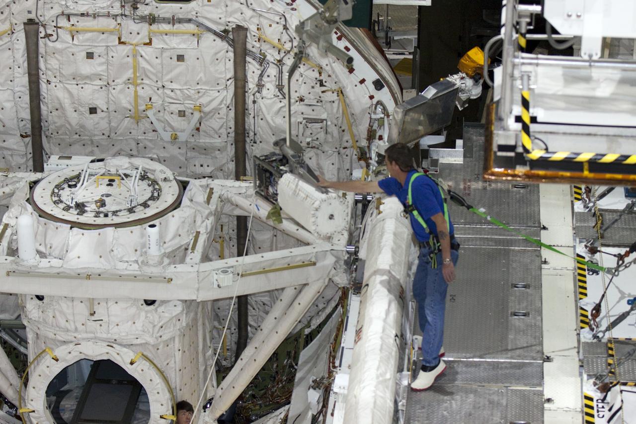
KENNEDY SPACE CENTER, FLA. - In NASA Kennedy Space Center’s Orbiter Processing Facility bay 3, a fuel cell removed from the orbiter Discovery is lowered toward the floor. Fuel cells are located under the forward portion of the payload bay. They make power for the orbiter by mixing hydrogen and oxygen to produce electricity. Fuel cells also create potable water that is pumped into storage tanks for the crew to use in orbit. Discovery is the designated orbiter for the second return-to-flight mission, STS-121, scheduled for launch in May. Photo credit: NASA/Kim Shiflett
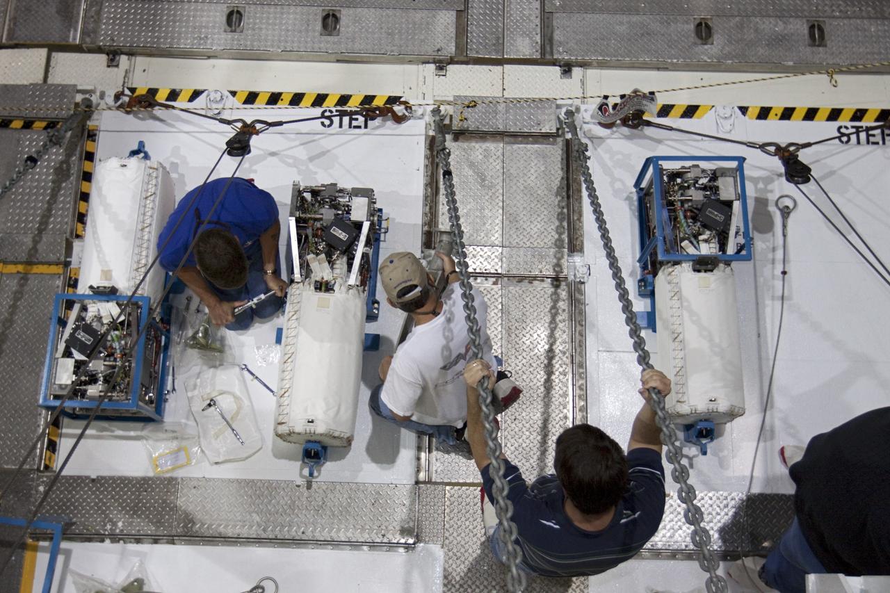
KENNEDY SPACE CENTER, FLA. - In NASA Kennedy Space Center’s Orbiter Processing Facility bay 3, technicians begin dismantling the fuel cell removed from the orbiter Discovery. Fuel cells are located under the forward portion of the payload bay. They make power for the orbiter by mixing hydrogen and oxygen to produce electricity. Fuel cells also create potable water that is pumped into storage tanks for the crew to use in orbit. Discovery is the designated orbiter for the second return-to-flight mission, STS-121, scheduled for launch in May. Photo credit: NASA/Kim Shiflett
KENNEDY SPACE CENTER, FLA. - In NASA Kennedy Space Center’s Orbiter Processing Facility bay 3, the fuel cell removed from the orbiter Discovery is lowered onto a bracket on the work stand. Fuel cells are located under the forward portion of the payload bay. They make power for the orbiter by mixing hydrogen and oxygen to produce electricity. Fuel cells also create potable water that is pumped into storage tanks for the crew to use in orbit. Discovery is the designated orbiter for the second return-to-flight mission, STS-121, scheduled for launch in May. Photo credit: NASA/Kim Shiflett
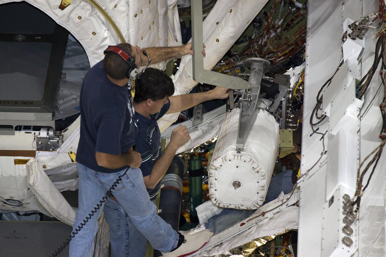
KENNEDY SPACE CENTER, FLA. - In NASA Kennedy Space Center’s Orbiter Processing Facility bay 3, technicians begin removing a piece of hardware from the side of a fuel cell removed from the orbiter Discovery. Fuel cells are located under the forward portion of the payload bay. They make power for the orbiter by mixing hydrogen and oxygen to produce electricity. Fuel cells also create potable water that is pumped into storage tanks for the crew to use in orbit. Discovery is the designated orbiter for the second return-to-flight mission, STS-121, scheduled for launch in May. Photo credit: NASA/Kim Shiflett

KENNEDY SPACE CENTER, FLA. - In NASA Kennedy Space Center’s Orbiter Processing Facility bay 3, technicians remove a piece of hardware from the side of a fuel cell removed from the orbiter Discovery. Fuel cells are located under the forward portion of the payload bay. They make power for the orbiter by mixing hydrogen and oxygen to produce electricity. Fuel cells also create potable water that is pumped into storage tanks for the crew to use in orbit. Discovery is the designated orbiter for the second return-to-flight mission, STS-121, scheduled for launch in May. Photo credit: NASA/Kim Shiflett
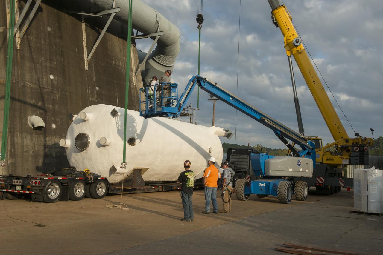
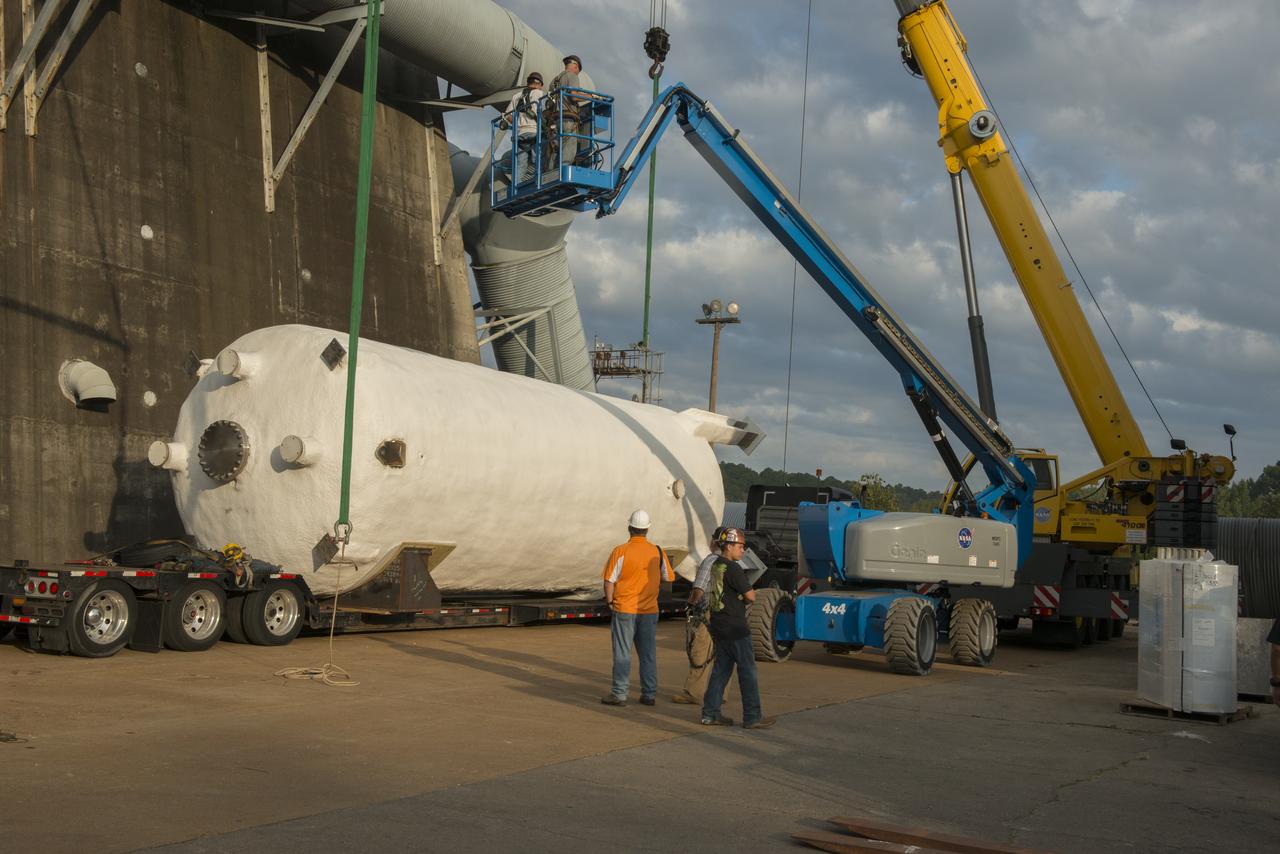
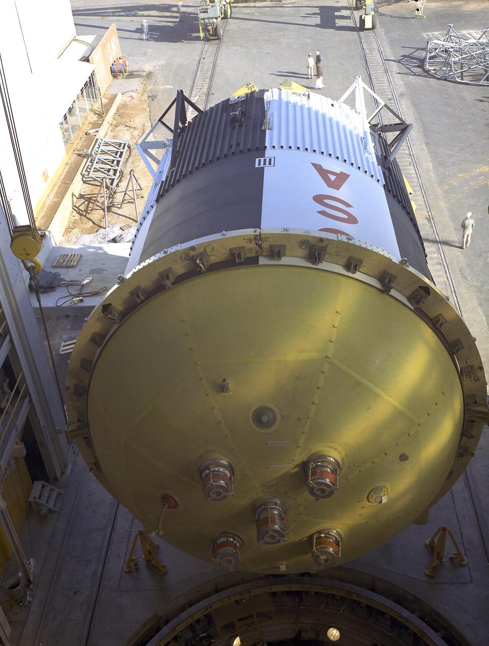
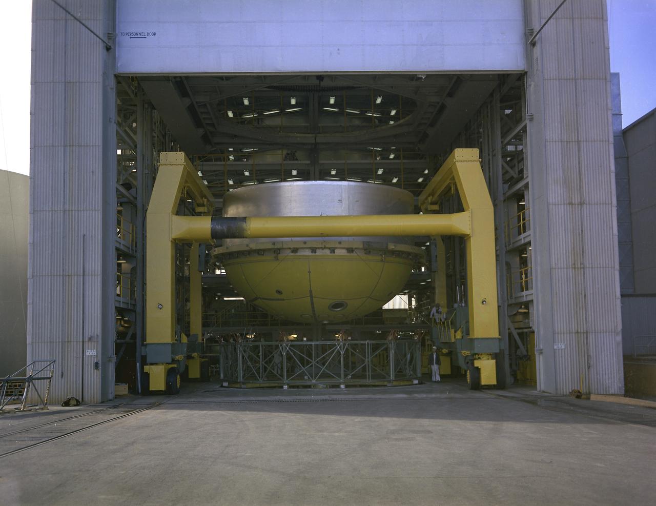
BOEING HIGH CAPACITY FUEL TANK BEING READIED FOR PLACEMENT ON WEST TEST AREA TEST STAND IN ANTICIPATION OF FURTHER TESTING.
BOEING HIGH CAPACITY FUEL TANK BEING READIED FOR PLACEMENT ON WEST TEST AREA TEST STAND IN ANTICIPATION OF FURTHER TESTING.
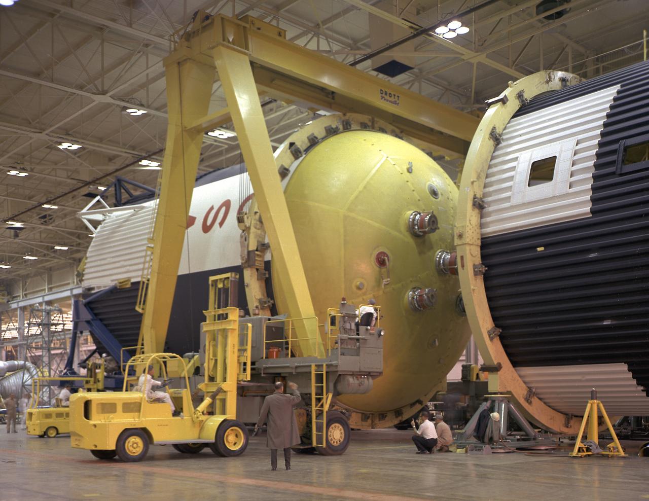
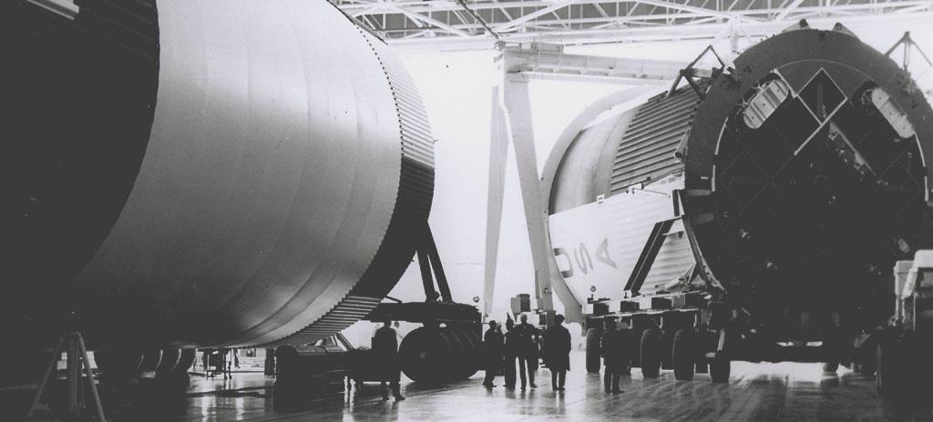
This photograph shows how the fuel tank assembly and the liquid oxygen tank for the Saturn V S-IC (first) stage are placed side by side prior to commencement of the mating of the two stages in the Marshall Space Flight Center, building 4705. The fuel tank carried kerosene as its fuel. The S-IC stage used five F-1 engines, that used kerosene and liquid oxygen as propellant and each engine provided 1,500,000 pounds of thrust. This stage lifted the entire vehicle and Apollo spacecraft from the launch pad.
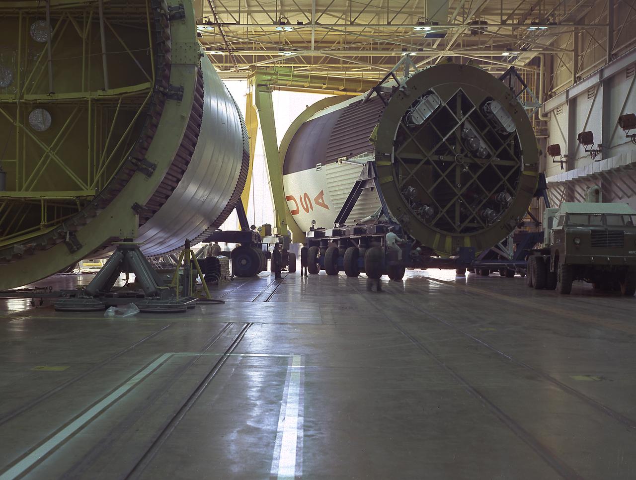
The fuel tank assembly for the Saturn V S-IC (first) stage arrived at the Marshall Space Flight Center, building 4707, for mating to the liquid oxygen tank. The fuel tank carried kerosene as its fuel. The S-IC stage used five F-1 engines, that used kerosene and liquid oxygen as propellant and each engine provided 1,500,000 pounds of thrust. This stage lifted the entire vehicle and Apollo spacecraft from the launch pad.
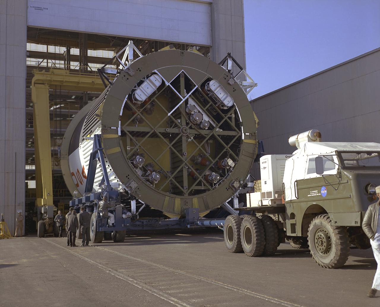
This photograph shows the fuel tank assembly for the Saturn V S-IC (first) stage being transported to the Marshall Space Flight Center, building 4705 for mating to the liquid oxygen (LOX) tank. The fuel tank carried kerosene (RP-1) as its fuel. The S-IC stage used five F-1 engines, that used kerosene and liquid oxygen as propellant and each engine provided 1,500,000 pounds of thrust. This stage lifted the entire vehicle and Apollo spacecraft from the launch pad.
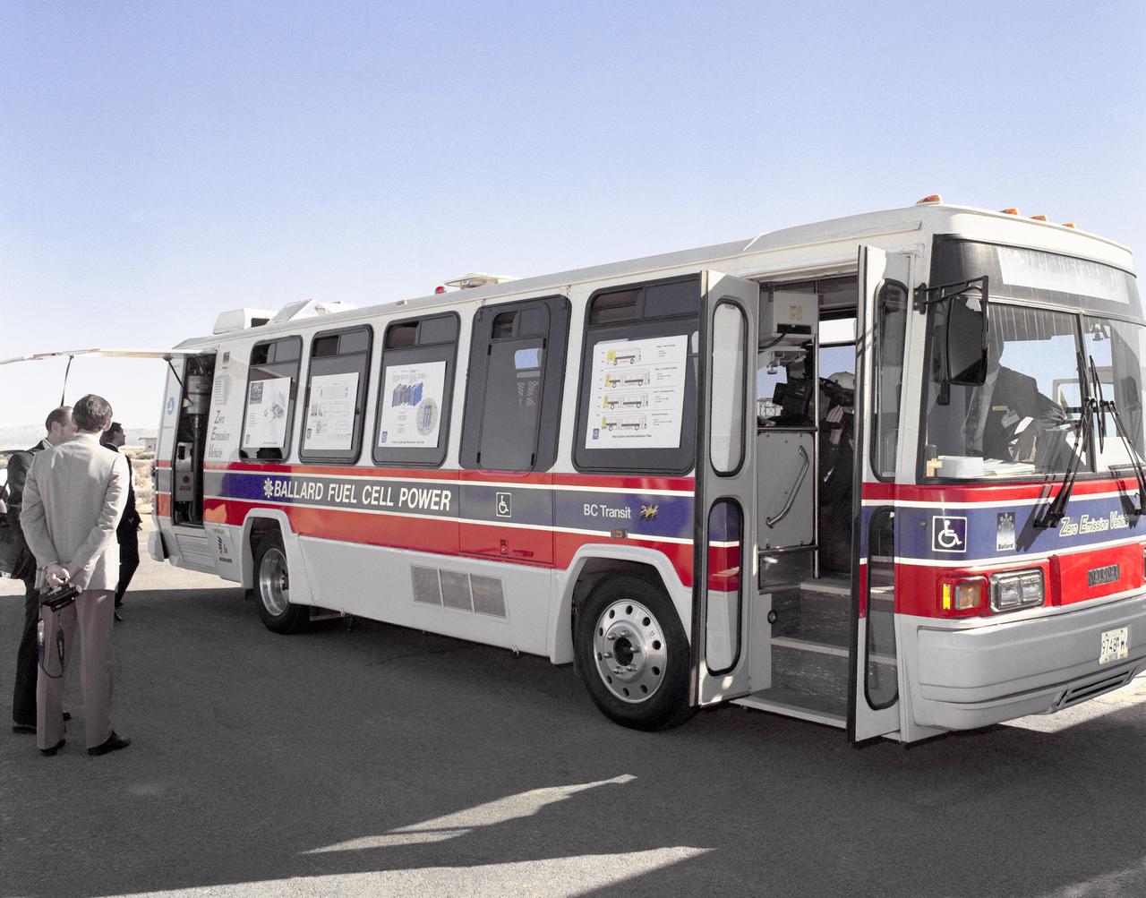
Fuel Cell Powered Bus
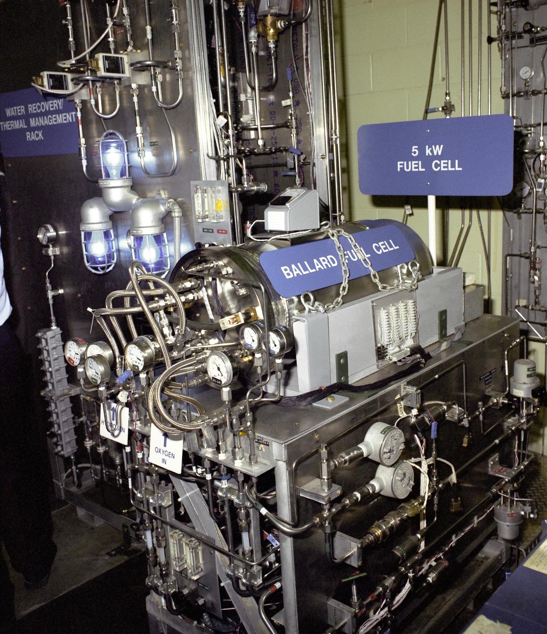
Fuel Cell for Bus

Fuel Cell Powered Bus
The fuel tank assembly of the Saturn V S-IC (first) stage is readied to be mated to the liquid oxygen tank at the Marshall Space Flight Center. The fuel tank carried kerosene as its fuel. The S-IC stage utilized five F-1 engines that used kerosene and liquid oxygen as propellant. Each engine provided 1,500,000 pounds of thrust. This stage lifted the entire vehicle and Apollo spacecraft from the launch pad.
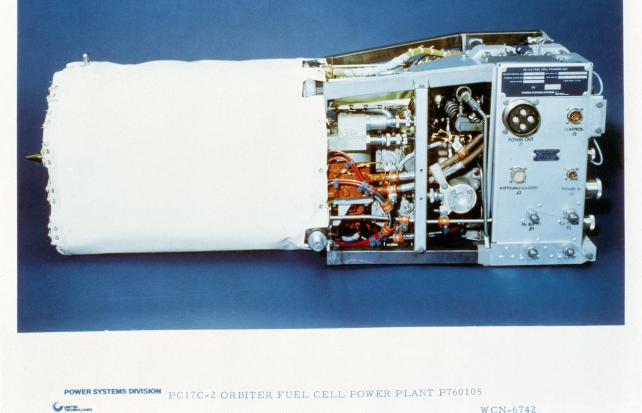
View of the PC17C-2 Orbiter Fuel Cell Power Plant P760105 From United Technologies Hamilton-Standard.
The components of the Saturn V booster (S-IC stage) fuel tank are shown in this photograph. The liquid oxygen tank bulkhead on the left and both halves of the fuel tank were in the Marshall Space Flight Center (MSFC) Manufacturing Engineering Laboratory, building 4707. These components were used at MSFC in structural testing to prove that they could withstand the forces to which they were subjected in flight. Each S-IC stage has two tanks, one for kerosene and one for liquid oxygen, made from such components as these. Thirty-three feet in diameter, they hold a total of 4,400,000 pounds of fuel. Although this tankage was assembled at MSFC, the elements were made by the Boeing Company at Wichita and the Michoud Operations at New Orleans.

An Astro Camp counselor and her campers perform a science experiment to learn what types of `fuel' will best propel their 'rockets.' Stennis Space Center's popular series of day camps have campers design, build and test model rockets based on the principles that would be used to build different types of rockets suitable for a mission to the moon or Mars. They learn details like how far they would travel, how long it would take, what supplies they would need and how to survive in that environment.
![A researcher at the National Advisory Committee for Aeronautics (NACA) Aircraft Engine Research Laboratory studies the fuel ignition process. Improved fuels and lubrication was an area of particular emphasis at the laboratory during World War II. The military sought to use existing types of piston engines in order to get large numbers of aircraft into the air as quickly as possible. To accomplish its goals, however, the military needed to increase the performance of these engines without having to wait for new models or extensive redesigns. The Aircraft Engine Research Laboratory was called on to lead this effort. The use of superchargers successfully enhanced engine performance, but the resulting heat increased engine knock [fuel detonation] and structural wear. These effects could be offset with improved cooling, lubrication, and fuel mixtures. The NACA researchers in the Fuels and Lubrication Division concentrated on new synthetic fuels, higher octane fuels, and fuel-injection systems. The laboratory studied 16 different types of fuel blends during the war, including extensive investigations of triptane and xylidine.](https://images-assets.nasa.gov/image/GRC-1943-C-02124/GRC-1943-C-02124~medium.jpg)
A researcher at the National Advisory Committee for Aeronautics (NACA) Aircraft Engine Research Laboratory studies the fuel ignition process. Improved fuels and lubrication was an area of particular emphasis at the laboratory during World War II. The military sought to use existing types of piston engines in order to get large numbers of aircraft into the air as quickly as possible. To accomplish its goals, however, the military needed to increase the performance of these engines without having to wait for new models or extensive redesigns. The Aircraft Engine Research Laboratory was called on to lead this effort. The use of superchargers successfully enhanced engine performance, but the resulting heat increased engine knock [fuel detonation] and structural wear. These effects could be offset with improved cooling, lubrication, and fuel mixtures. The NACA researchers in the Fuels and Lubrication Division concentrated on new synthetic fuels, higher octane fuels, and fuel-injection systems. The laboratory studied 16 different types of fuel blends during the war, including extensive investigations of triptane and xylidine.
This photograph shows the components for the Saturn V S-IC stage fuel tank assembly in the Manufacturing Engineering Laboratory, building 4707, at the Marshall Space Flight Center (MSFC). Left to right are upper head, lower head, and forward skirt assembly. Thirty-three feet in diameter, they will hold a total of 4,400,000 pounds of fuel. Although this tankage was assembled at MSFC, the elements were made by the Boeing Company at Wichita and the Michould Operations at New Orleans.
CAPE CANAVERAL, Fla. – Inside Orbiter Processing Facility-2 at NASA's Kennedy Space Center in Florida, a crane hoists one of space shuttle Endeavour's three fuel cells out of the vehicle's payload bay. All three of Endeavour's fuel cells were removed and will be drained of fluids. The hydrogen and oxygen dewars which feed reactants to the fuel cells remain in Endeavour's midbody and will be purged with inert gases and vented down. The work is part of the Space Shuttle Program's transition and retirement processing of shuttle Endeavour, which is being prepared for public display at the California Science Center in Los Angeles. Its ferry flight to California is targeted for mid-September. Endeavour was the last space shuttle added to NASA's orbiter fleet. Over the course of its 19-year career, Endeavour spent 299 days in space during 25 missions. For more information, visit http://www.nasa.gov/shuttle. Photo credit: NASA/Glenn Benson
CAPE CANAVERAL, Fla. – Inside Orbiter Processing Facility-2 at NASA's Kennedy Space Center in Florida, a technician guides a newly removed fuel cell up and out of space shuttle Endeavour's payload bay. All three of Endeavour's fuel cells were removed and will be drained of fluids. The hydrogen and oxygen dewars which feed reactants to the fuel cells remain in Endeavour's midbody and will be purged with inert gases and vented down. The work is part of the Space Shuttle Program's transition and retirement processing of shuttle Endeavour, which is being prepared for public display at the California Science Center in Los Angeles. Its ferry flight to California is targeted for mid-September. Endeavour was the last space shuttle added to NASA's orbiter fleet. Over the course of its 19-year career, Endeavour spent 299 days in space during 25 missions. For more information, visit http://www.nasa.gov/shuttle. Photo credit: NASA/Glenn Benson

CAPE CANAVERAL, Fla. – Technicians inside Kennedy Space Center's Orbiter Processing Facility-2 lower one of space shuttle Endeavour's recently removed fuel cells onto a waiting platform. All three of Endeavour's fuel cells were removed and will be drained of fluids. The hydrogen and oxygen dewars which feed reactants to the fuel cells remain in Endeavour's midbody and will be purged with inert gases and vented down. The work is part of the Space Shuttle Program's transition and retirement processing of shuttle Endeavour, which is being prepared for public display at the California Science Center in Los Angeles. Its ferry flight to California is targeted for mid-September. Endeavour was the last space shuttle added to NASA's orbiter fleet. Over the course of its 19-year career, Endeavour spent 299 days in space during 25 missions. For more information, visit http://www.nasa.gov/shuttle. Photo credit: NASA/Glenn Benson
CAPE CANAVERAL, Fla. – Technicians inside Kennedy Space Center's Orbiter Processing Facility-2 lower one of space shuttle Endeavour's recently removed fuel cells onto a waiting platform. All three of Endeavour's fuel cells were removed and will be drained of fluids. The hydrogen and oxygen dewars which feed reactants to the fuel cells remain in Endeavour's midbody and will be purged with inert gases and vented down. The work is part of the Space Shuttle Program's transition and retirement processing of shuttle Endeavour, which is being prepared for public display at the California Science Center in Los Angeles. Its ferry flight to California is targeted for mid-September. Endeavour was the last space shuttle added to NASA's orbiter fleet. Over the course of its 19-year career, Endeavour spent 299 days in space during 25 missions. For more information, visit http://www.nasa.gov/shuttle. Photo credit: NASA/Glenn Benson
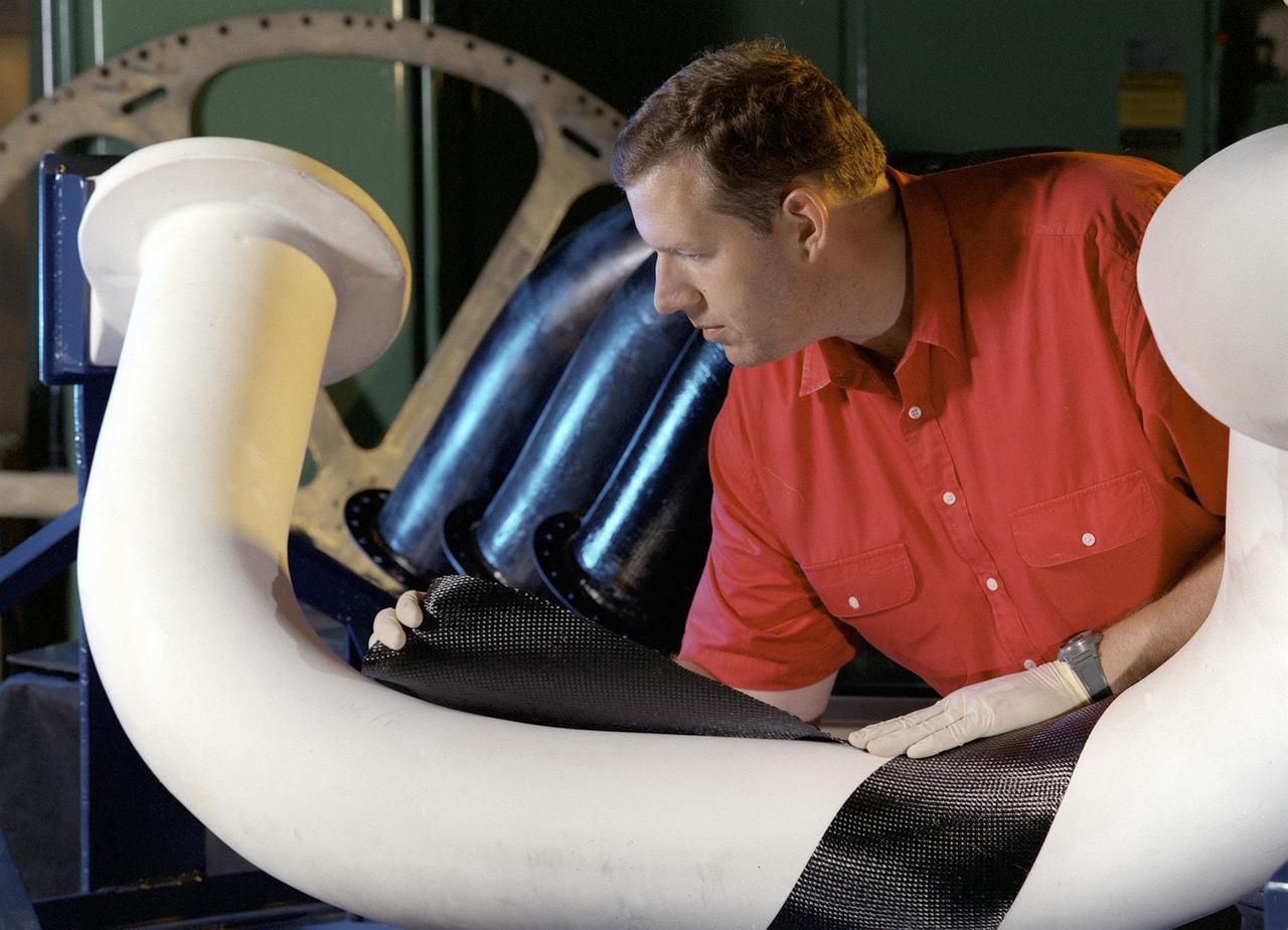
Engineers at Marshall Space Flight Center (MSFC) in Huntsville, Alabama, are working with industry partners to develop a new generation of more cost-efficient space vehicles. Lightweight fuel tanks and components under development will be the critical elements in tomorrow's reusable launch vehicles and will tremendously curb the costs of getting to space. In this photo, Tom DeLay, a materials processes engineer for MSFC, uses a new graphite epoxy technology to create lightweight cryogenic fuel lines for futuristic reusable launch vehicles. He is wrapping a water-soluble mandrel, or mold, with a graphite fabric coated with an epoxy resin. Once wrapped, the pipe will be vacuum-bagged and autoclave-cured. The disposable mold will be removed to reveal a thin-walled fuel line. In addition to being much lighter and stronger than metal, this material won't expand or contract as much in the extreme temperatures encountered by launch vehicles.
CAPE CANAVERAL, Fla. – Inside Orbiter Processing Facility-2 at NASA's Kennedy Space Center in Florida, technicians use a special crane to lift a fuel cell out of space shuttle Endeavour's payload bay. All three of Endeavour's fuel cells were removed and will be drained of fluids. The hydrogen and oxygen dewars which feed reactants to the fuel cells remain in Endeavour's midbody and will be purged with inert gases and vented down. The work is part of the Space Shuttle Program's transition and retirement processing of shuttle Endeavour, which is being prepared for public display at the California Science Center in Los Angeles. Its ferry flight to California is targeted for mid-September. Endeavour was the last space shuttle added to NASA's orbiter fleet. Over the course of its 19-year career, Endeavour spent 299 days in space during 25 missions. For more information, visit http://www.nasa.gov/shuttle. Photo credit: NASA/Glenn Benson
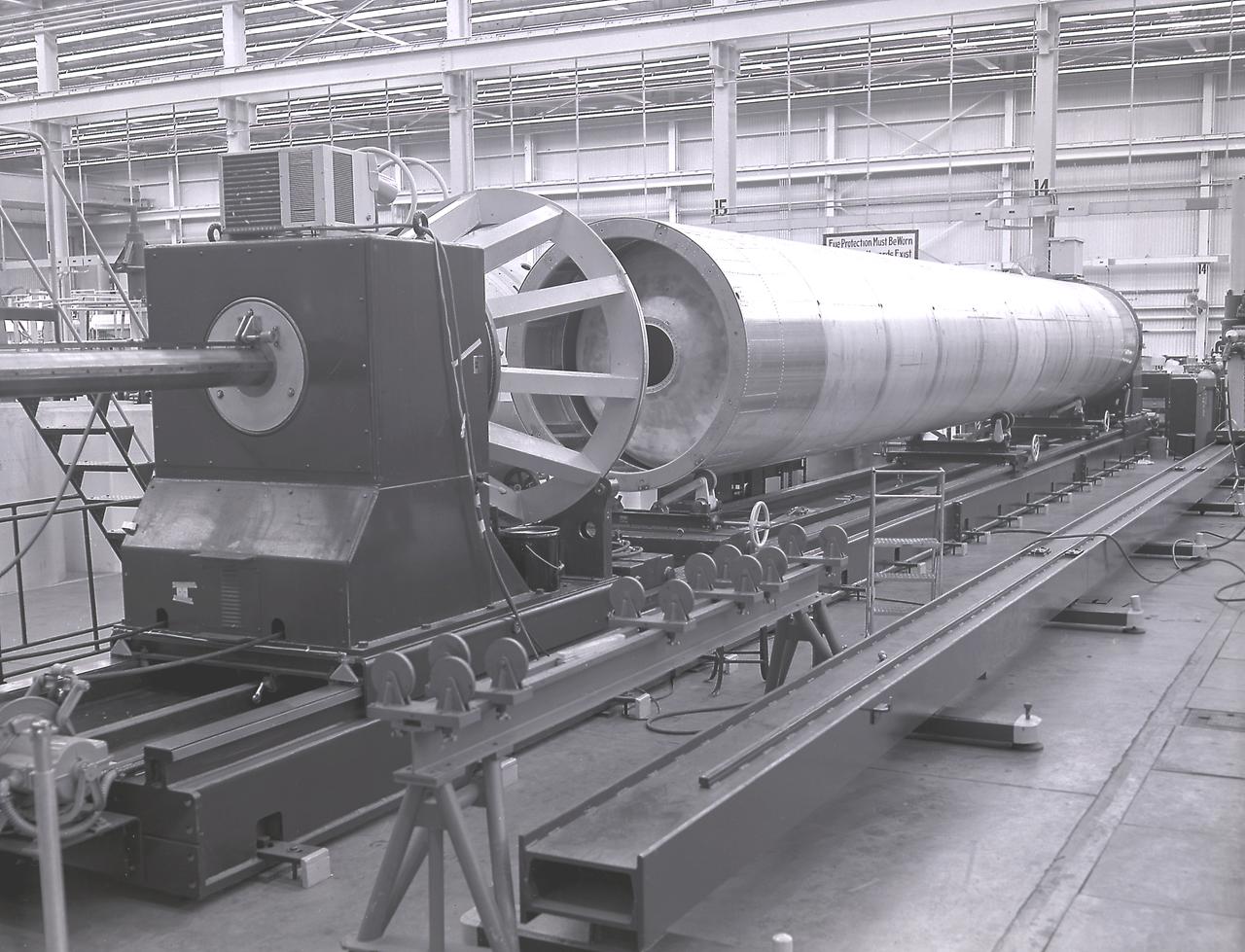
This photograph shows a fuel tank lower half for the Saturn V S-IC-T stage (the S-IC stage for static testing) on a C-frame transporter inside the vertical assembly building at the Marshall Space Flight Center.
This photograph shows a bulkhead for the Saturn V S-IC stage fuel tank being fabricated at the Manufacturing Engineering Laboratory, building 4704, at the Marshall Space Flight Center.
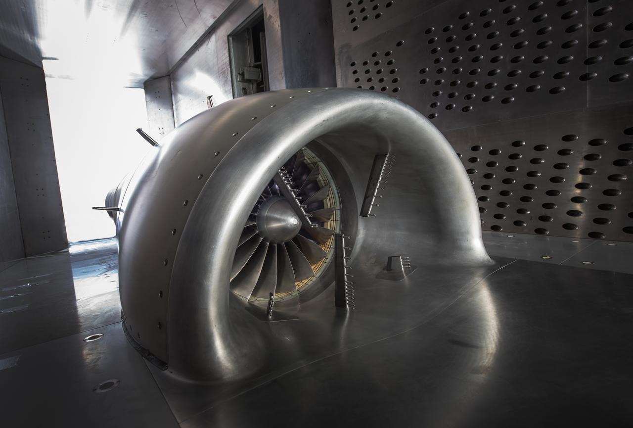
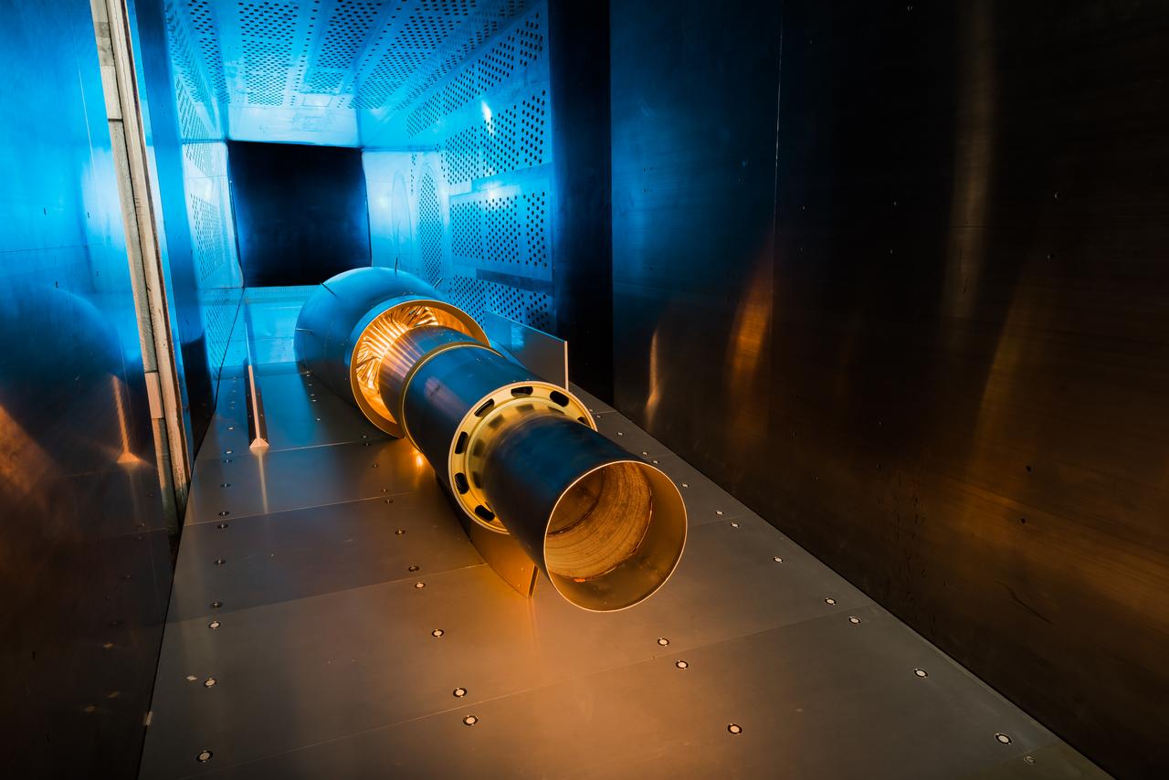
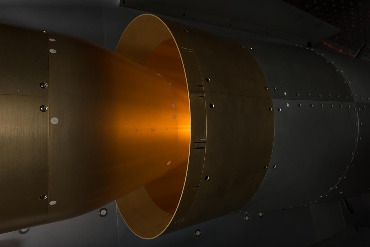
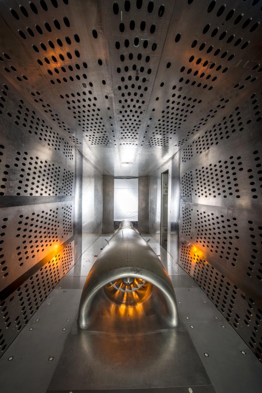
In an effort to improve fuel efficiency, NASA and the aircraft industry are rethinking aircraft design. Inside the 8' x 6' wind tunnel at NASA Glenn, engineers recently tested a fan and inlet design, commonly called a propulsor, which could use four to eight percent less fuel than today's advanced aircraft.
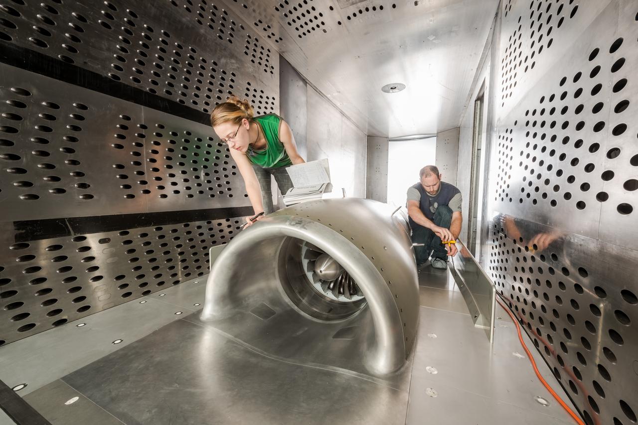
In an effort to improve fuel efficiency, NASA and the aircraft industry are rethinking aircraft design. Inside the 8' x 6' wind tunnel at NASA Glenn, engineers recently tested a fan and inlet design, commonly called a propulsor, which could use four to eight percent less fuel than today's advanced aircraft.
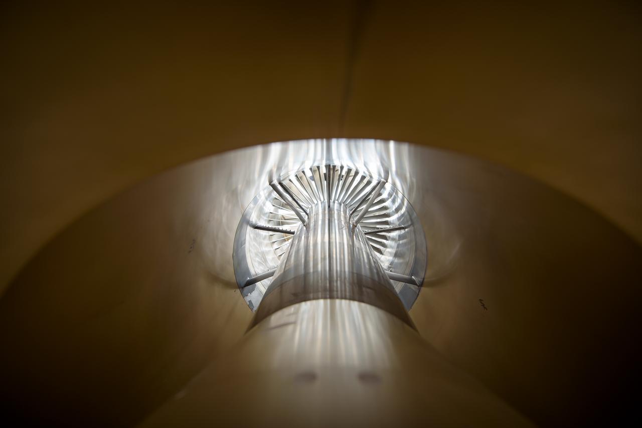
In an effort to improve fuel efficiency, NASA and the aircraft industry are rethinking aircraft design. Inside the 8' x 6' wind tunnel at NASA Glenn, engineers recently tested a fan and inlet design, commonly called a propulsor, which could use four to eight percent less fuel than today's advanced aircraft.
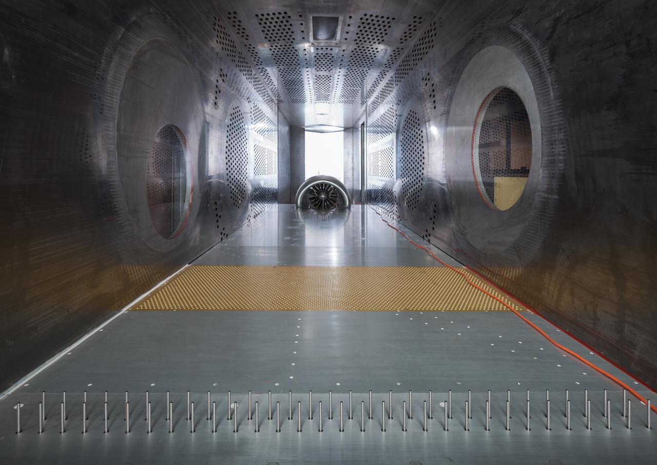
In an effort to improve fuel efficiency, NASA and the aircraft industry are rethinking aircraft design. Inside the 8' x 6' wind tunnel at NASA Glenn, engineers recently tested a fan and inlet design, commonly called a propulsor, which could use four to eight percent less fuel than today's advanced aircraft.
In an effort to improve fuel efficiency, NASA and the aircraft industry are rethinking aircraft design. Inside the 8' x 6' wind tunnel at NASA Glenn, engineers recently tested a fan and inlet design, commonly called a propulsor, which could use four to eight percent less fuel than today's advanced aircraft.
In an effort to improve fuel efficiency, NASA and the aircraft industry are rethinking aircraft design. Inside the 8' x 6' wind tunnel at NASA Glenn, engineers recently tested a fan and inlet design, commonly called a propulsor, which could use four to eight percent less fuel than today's advanced aircraft.
In an effort to improve fuel efficiency, NASA and the aircraft industry are rethinking aircraft design. Inside the 8' x 6' wind tunnel at NASA Glenn, engineers recently tested a fan and inlet design, commonly called a propulsor, which could use four to eight percent less fuel than today's advanced aircraft.

In an effort to improve fuel efficiency, NASA and the aircraft industry are rethinking aircraft design. Inside the 8' x 6' wind tunnel at NASA Glenn, engineers recently tested a fan and inlet design, commonly called a propulsor, which could use four to eight percent less fuel than today's advanced aircraft.

In an effort to improve fuel efficiency, NASA and the aircraft industry are rethinking aircraft design. Inside the 8' x 6' wind tunnel at NASA Glenn, engineers recently tested a fan and inlet design, commonly called a propulsor, which could use four to eight percent less fuel than today's advanced aircraft.
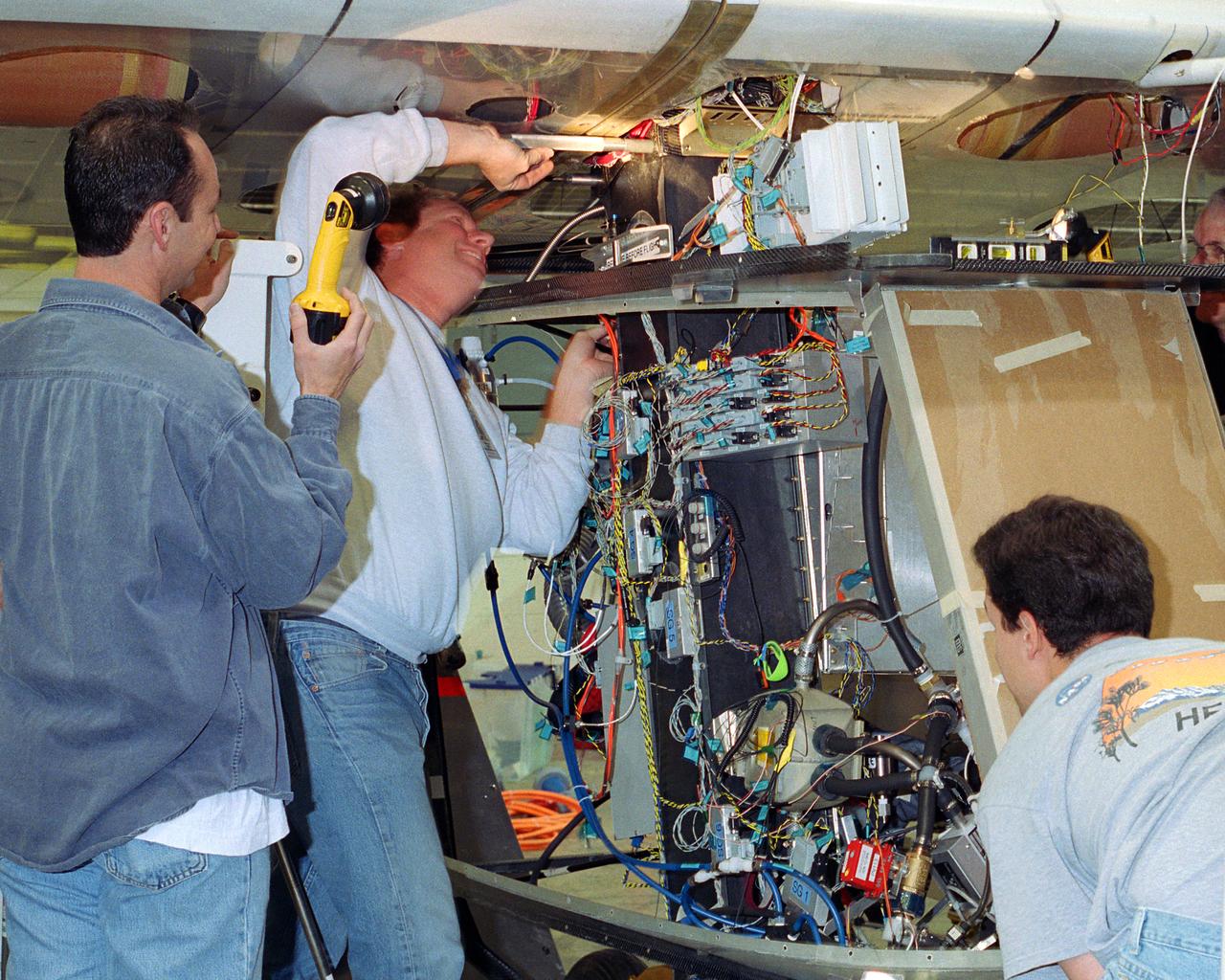
Aerovironment technicians carefully line up attachments as a fuel cell electrical system is installed on the Helios Prototype solar powered flying wing. The fuel cell system will power the aircraft at night during NASA-sponsored long-endurance demonstration flight in the summer of 2003.
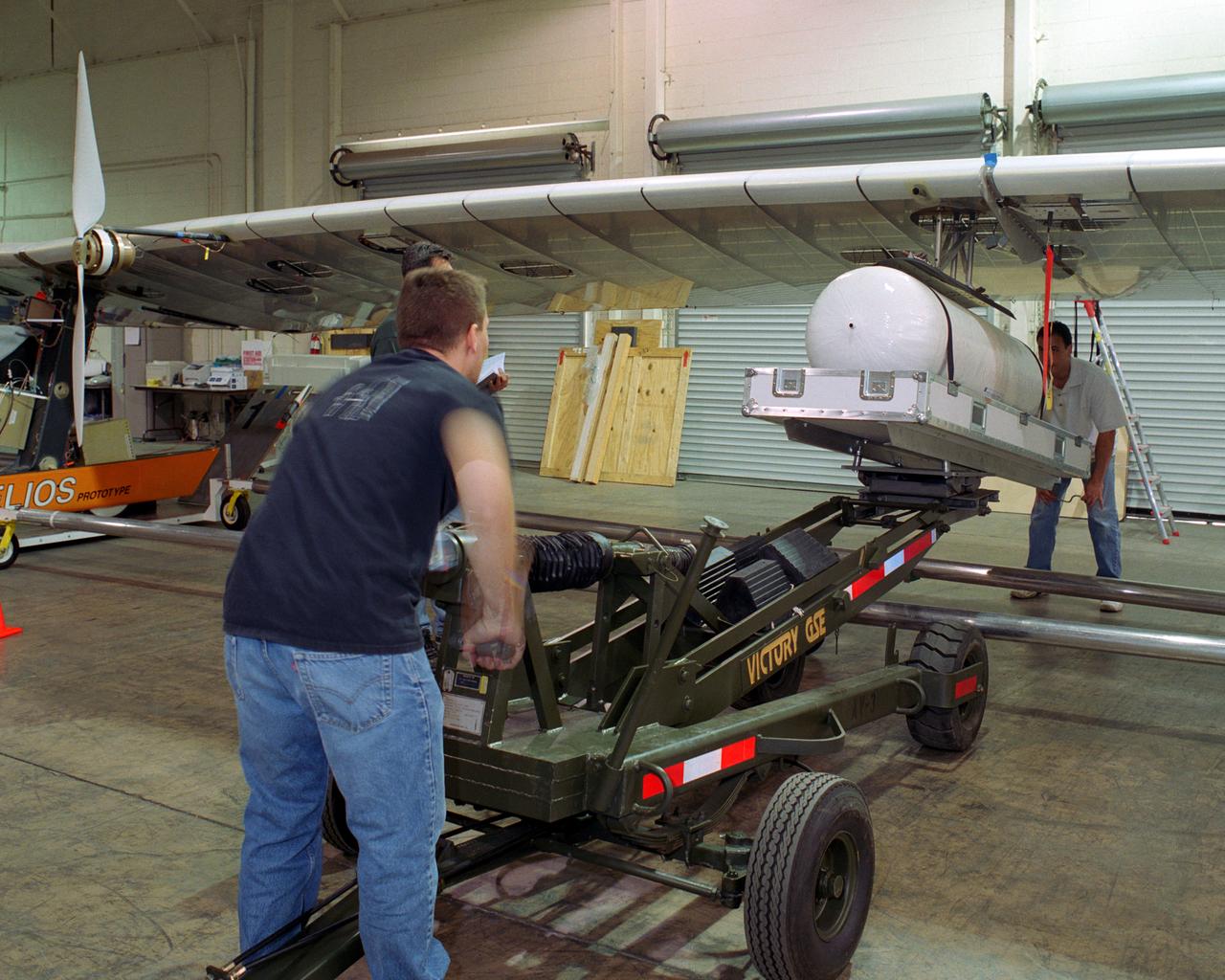
Technicians for AeroVironment, Inc., jack up a pressure tank to the wing of the Helios Prototype solar-electric flying wing. The tank carries pressurized hydrogen to fuel an experimental fuel cell system that powered the aircraft at night during an almost two-day long-endurance flight demonstration in the summer of 2003.
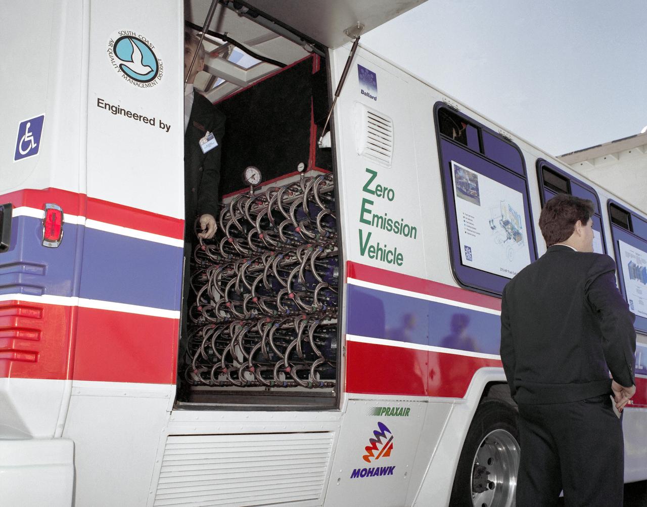
Fuel Cell Powered Bus - closup of installed cells
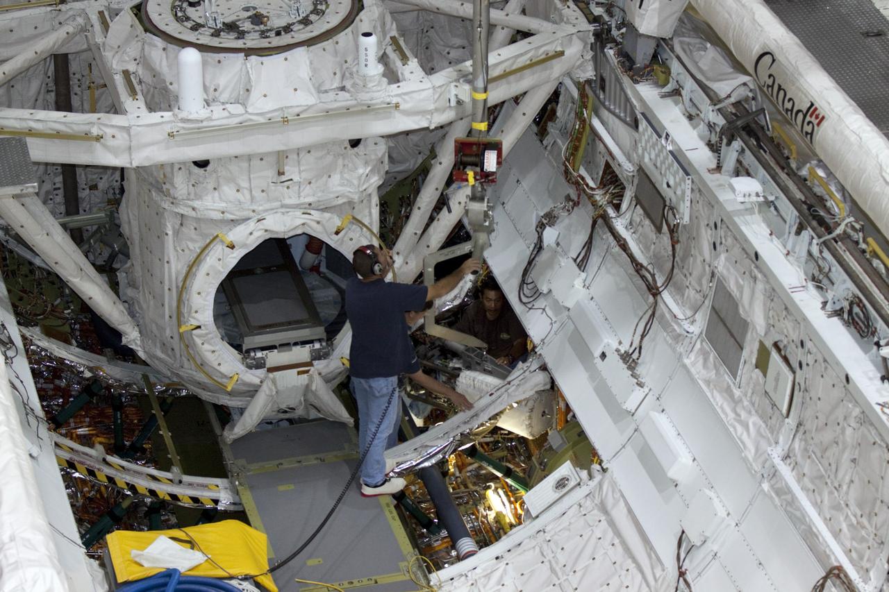
CAPE CANAVERAL, Fla. – Inside Orbiter Processing Facility-2 at NASA’s Kennedy Space Center in Florida, space shuttle Atlantis’ three fuel cells are being removed from the payload bay. The fuel cells will be drained of all fluids. The hydrogen and oxygen dewars which feed reactants to the fuel cells remain in Atlantis’ mid-body and will be purged with inert gases and vented down. The work is part of the Space Shuttle Program’s transition and retirement processing of shuttle Atlantis. The orbiter is being prepared for display at the Kennedy Space Center Visitor Complex. Photo credit: NASA/Kim Shiflett
CAPE CANAVERAL, Fla. – Inside Orbiter Processing Facility-2 at NASA’s Kennedy Space Center in Florida, technicians help position a special crane in place to lift one of the three fuel cells away from space shuttle Atlantis’ payload bay. The fuel cells will be drained of all fluids. The hydrogen and oxygen dewars which feed reactants to the fuel cells remain in Atlantis’ mid-body and will be purged with inert gases and vented down. The work is part of the Space Shuttle Program’s transition and retirement processing of shuttle Atlantis. The orbiter is being prepared for display at the Kennedy Space Center Visitor Complex. Photo credit: NASA/Kim Shiflett
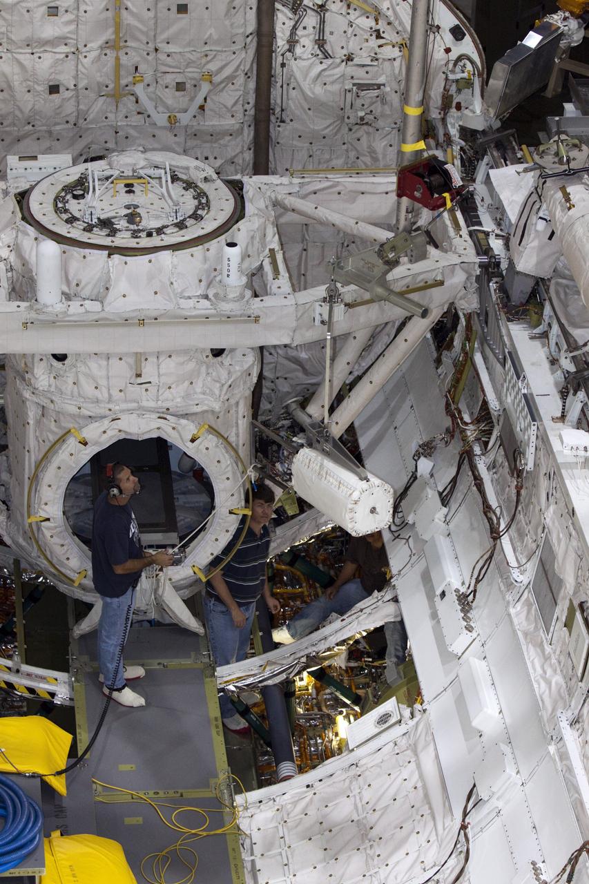
CAPE CANAVERAL, Fla. – Inside Orbiter Processing Facility-2 at NASA’s Kennedy Space Center in Florida, technicians monitor the progress as a special crane lifts one of the three fuel cells away from space shuttle Atlantis’ payload bay. The fuel cells will be drained of all fluids. The hydrogen and oxygen dewars which feed reactants to the fuel cells remain in Atlantis’ mid-body and will be purged with inert gases and vented down. The work is part of the Space Shuttle Program’s transition and retirement processing of shuttle Atlantis. The orbiter is being prepared for display at the Kennedy Space Center Visitor Complex. Photo credit: NASA/Kim Shiflett
CAPE CANAVERAL, Fla. – Inside Orbiter Processing Facility-2 at NASA’s Kennedy Space Center in Florida, a technician assists as a special crane lifts one of the three fuel cells away from space shuttle Atlantis’ payload bay. The fuel cells will be drained of all fluids. The hydrogen and oxygen dewars which feed reactants to the fuel cells remain in Atlantis’ mid-body and will be purged with inert gases and vented down. The work is part of the Space Shuttle Program’s transition and retirement processing of shuttle Atlantis. The orbiter is being prepared for display at the Kennedy Space Center Visitor Complex. Photo credit: NASA/Kim Shiflett
CAPE CANAVERAL, Fla. – Inside Orbiter Processing Facility-2 at NASA’s Kennedy Space Center in Florida, technicians prepare to remove one of three fuel cells from space shuttle Atlantis’ payload bay. The fuel cells will be drained of all fluids. The hydrogen and oxygen dewars which feed reactants to the fuel cells remain in Atlantis’ mid-body and will be purged with inert gases and vented down. The work is part of the Space Shuttle Program’s transition and retirement processing of shuttle Atlantis. The orbiter is being prepared for display at the Kennedy Space Center Visitor Complex. Photo credit: NASA/Kim Shiflett
CAPE CANAVERAL, Fla. – Inside Orbiter Processing Facility-2 at NASA’s Kennedy Space Center in Florida, technicians monitor the progress as a special crane lifts one of the three fuel cells away from space shuttle Atlantis’ payload bay. The fuel cells will be drained of all fluids. The hydrogen and oxygen dewars which feed reactants to the fuel cells remain in Atlantis’ mid-body and will be purged with inert gases and vented down. The work is part of the Space Shuttle Program’s transition and retirement processing of shuttle Atlantis. The orbiter is being prepared for display at the Kennedy Space Center Visitor Complex. Photo credit: NASA/Kim Shiflett
CAPE CANAVERAL, Fla. – Inside Orbiter Processing Facility-2 at NASA’s Kennedy Space Center in Florida, technicians assist as a special crane is used to lift one of the three fuel cells away from space shuttle Atlantis’ payload bay. The fuel cells will be drained of all fluids. The hydrogen and oxygen dewars which feed reactants to the fuel cells remain in Atlantis’ mid-body and will be purged with inert gases and vented down. The work is part of the Space Shuttle Program’s transition and retirement processing of shuttle Atlantis. The orbiter is being prepared for display at the Kennedy Space Center Visitor Complex. Photo credit: NASA/Kim Shiflett
CAPE CANAVERAL, Fla. – Inside Orbiter Processing Facility-2 at NASA’s Kennedy Space Center in Florida, a technician assists as a special crane is used to lift one of the three fuel cells away from space shuttle Atlantis’ payload bay. The fuel cells will be drained of all fluids. The hydrogen and oxygen dewars which feed reactants to the fuel cells remain in Atlantis’ mid-body and will be purged with inert gases and vented down. The work is part of the Space Shuttle Program’s transition and retirement processing of shuttle Atlantis. The orbiter is being prepared for display at the Kennedy Space Center Visitor Complex. Photo credit: NASA/Kim Shiflett
CAPE CANAVERAL, Fla. – Inside Orbiter Processing Facility-2 at NASA’s Kennedy Space Center in Florida, technicians secure space shuttle Atlantis’ three fuel cells to special platforms. The fuel cells will be drained of all fluids. The hydrogen and oxygen dewars which feed reactants to the fuel cells remain in Atlantis’ mid-body and will be purged with inert gases and vented down. The work is part of the Space Shuttle Program’s transition and retirement processing of shuttle Atlantis. The orbiter is being prepared for display at the Kennedy Space Center Visitor Complex. Photo credit: NASA/Kim Shiflett
CAPE CANAVERAL, Fla. – Inside Orbiter Processing Facility-2 at NASA’s Kennedy Space Center in Florida, technicians assist as a special crane is used to lift one of the three fuel cells away from space shuttle Atlantis’ payload bay. The fuel cells will be drained of all fluids. The hydrogen and oxygen dewars which feed reactants to the fuel cells remain in Atlantis’ mid-body and will be purged with inert gases and vented down. The work is part of the Space Shuttle Program’s transition and retirement processing of shuttle Atlantis. The orbiter is being prepared for display at the Kennedy Space Center Visitor Complex. Photo credit: NASA/Kim Shiflett
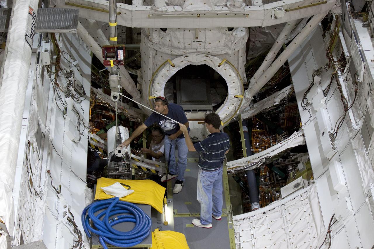
CAPE CANAVERAL, Fla. – Inside Orbiter Processing Facility-2 at NASA’s Kennedy Space Center in Florida, technicians prepare to remove one of three fuel cells from space shuttle Atlantis’ payload bay. The fuel cells will be drained of all fluids. The hydrogen and oxygen dewars which feed reactants to the fuel cells remain in Atlantis’ mid-body and will be purged with inert gases and vented down. The work is part of the Space Shuttle Program’s transition and retirement processing of shuttle Atlantis. The orbiter is being prepared for display at the Kennedy Space Center Visitor Complex. Photo credit: NASA/Kim Shiflett
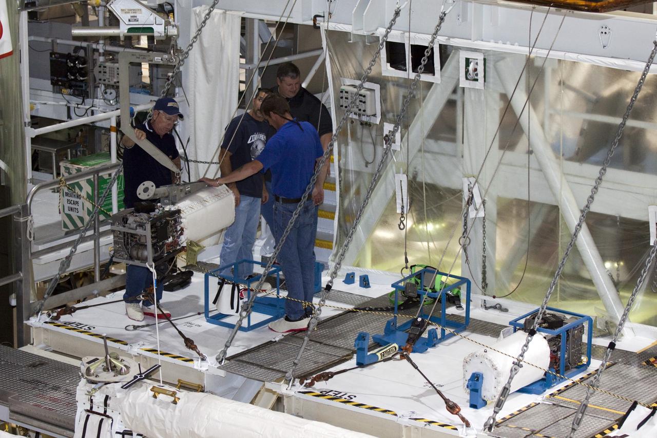
CAPE CANAVERAL, Fla. – Inside Orbiter Processing Facility-2 at NASA’s Kennedy Space Center in Florida, technicians monitor the progress as a special crane lifts one of the three fuel cells away from space shuttle Atlantis’ for securing on a special platform. The fuel cells will be drained of all fluids. The hydrogen and oxygen dewars which feed reactants to the fuel cells remain in Atlantis’ mid-body and will be purged with inert gases and vented down. The work is part of the Space Shuttle Program’s transition and retirement processing of shuttle Atlantis. The orbiter is being prepared for display at the Kennedy Space Center Visitor Complex. Photo credit: NASA/Kim Shiflett
CAPE CANAVERAL, Fla. – Inside Orbiter Processing Facility-2 at NASA’s Kennedy Space Center in Florida, technicians monitor the progress as a special crane lifts one of the three fuel cells away from space shuttle Atlantis’ payload bay. The fuel cells will be drained of all fluids. The hydrogen and oxygen dewars which feed reactants to the fuel cells remain in Atlantis’ mid-body and will be purged with inert gases and vented down. The work is part of the Space Shuttle Program’s transition and retirement processing of shuttle Atlantis. The orbiter is being prepared for display at the Kennedy Space Center Visitor Complex. Photo credit: NASA/Kim Shiflett
CAPE CANAVERAL, Fla. – Inside Orbiter Processing Facility-2 at NASA’s Kennedy Space Center in Florida, technicians assist as a special crane is used to lift one of the three fuel cells away from space shuttle Atlantis’ payload bay. The fuel cells will be drained of all fluids. The hydrogen and oxygen dewars which feed reactants to the fuel cells remain in Atlantis’ mid-body and will be purged with inert gases and vented down. The work is part of the Space Shuttle Program’s transition and retirement processing of shuttle Atlantis. The orbiter is being prepared for display at the Kennedy Space Center Visitor Complex. Photo credit: NASA/Kim Shiflett
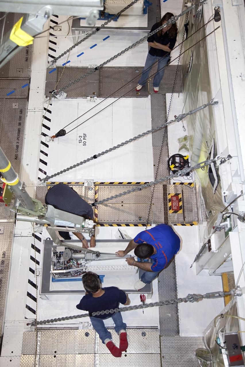
Workers prepare the Robotic Refueling Mission-3 (RRM3) payload for transport from the Fuel Transfer Building to the SpaceX facility on Oct. 30, 2018, at NASA's Kennedy Space Center in Florida. The payload will be carried to the International Space Station on SpaceX's 16th Commercial Resupply Services mission. RRM3 demonstrates the transfer of xenon gas and liquid methane in microgravity, and advances technologies for storing and manipulating these cryogenic fuels robotically. RRM3 also supports development of technology for the Restore-L mission, a robotic spacecraft equipped to service satellites in-orbit.
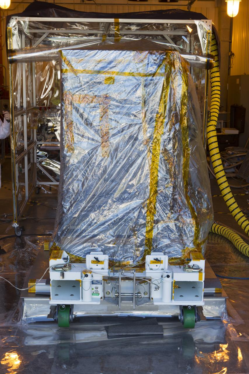
The Robotic Refueling Mission-3 (RRM3) payload is being prepared to be moved from the Fuel Transfer Building to the SpaceX facility on Oct. 30, 2018, at NASA's Kennedy Space Center in Florida. The payload will be carried to the International Space Station on SpaceX's 16th Commercial Resupply Services mission. RRM3 demonstrates the transfer of xenon gas and liquid methane in microgravity, and advances technologies for storing and manipulating these cryogenic fuels robotically. RRM3 also supports development of technology for the Restore-L mission, a robotic spacecraft equipped to service satellites in-orbit.
CAPE CANAVERAL, Fla. – Technicians monitor the progress as one of space shuttle Endeavour's three fuel cells is removed from the vehicle's payload bay. The operation took place inside Orbiter Processing Facility-2 at NASA's Kennedy Space Center in Florida. All three of Endeavour's fuel cells were removed and will be drained of fluids. The hydrogen and oxygen dewars which feed reactants to the fuel cells remain in Endeavour's midbody and will be purged with inert gases and vented down. The work is part of the Space Shuttle Program's transition and retirement processing of shuttle Endeavour, which is being prepared for public display at the California Science Center in Los Angeles. Its ferry flight to California is targeted for mid-September. Endeavour was the last space shuttle added to NASA's orbiter fleet. Over the course of its 19-year career, Endeavour spent 299 days in space during 25 missions. For more information, visit http://www.nasa.gov/shuttle. Photo credit: NASA/Glenn Benson
Marshall Space Flight Center successfully conducted hydrostatic testing on the Saturn V S-IC (first) stage fuel tank. The first stage was powered by five F-1 engines, that used liquid oxygen and kerosene as its propellant.
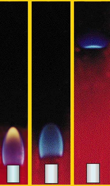
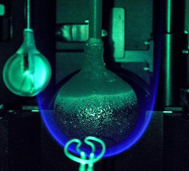
Image taken during a ground based investigation of a methane-fueled laminar flame surrounded by co-flowing air. The flame was enclosed in a chamber, and the pressure reduced. As the pressure decreased, the velocity of the flow increased, causing the flame to change from a stabilized condition to near blow-out or extinction.
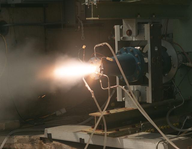
Solid fuel test performed on the Fastrac II engine cell at Marshall's Test Stand 116.
The first circumferential welding being applied on a Saturn fuel container in the Army Ballistic Missile Agency (ABMA) fabrication laboratory, Building 4707, in May 1959.
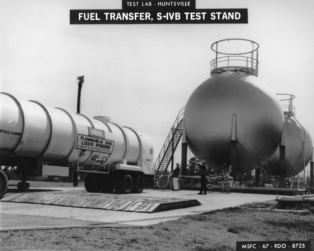
Marshall Space Flight Center (MSFC) workers fill fuel tanks with liquid hydrogen used for test firing at the S-IVB (Dynamic) Test Stand.
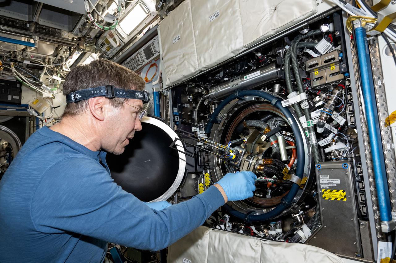
iss071e439784 (Aug. 5, 2024) --- NASA astronaut and Expedition 71 Flight Engineer Mike Barratt replaces fuel bottles and other components inside the Combustion Integrated Rack located inside the Intenational Space Station's Destiny laboratory.
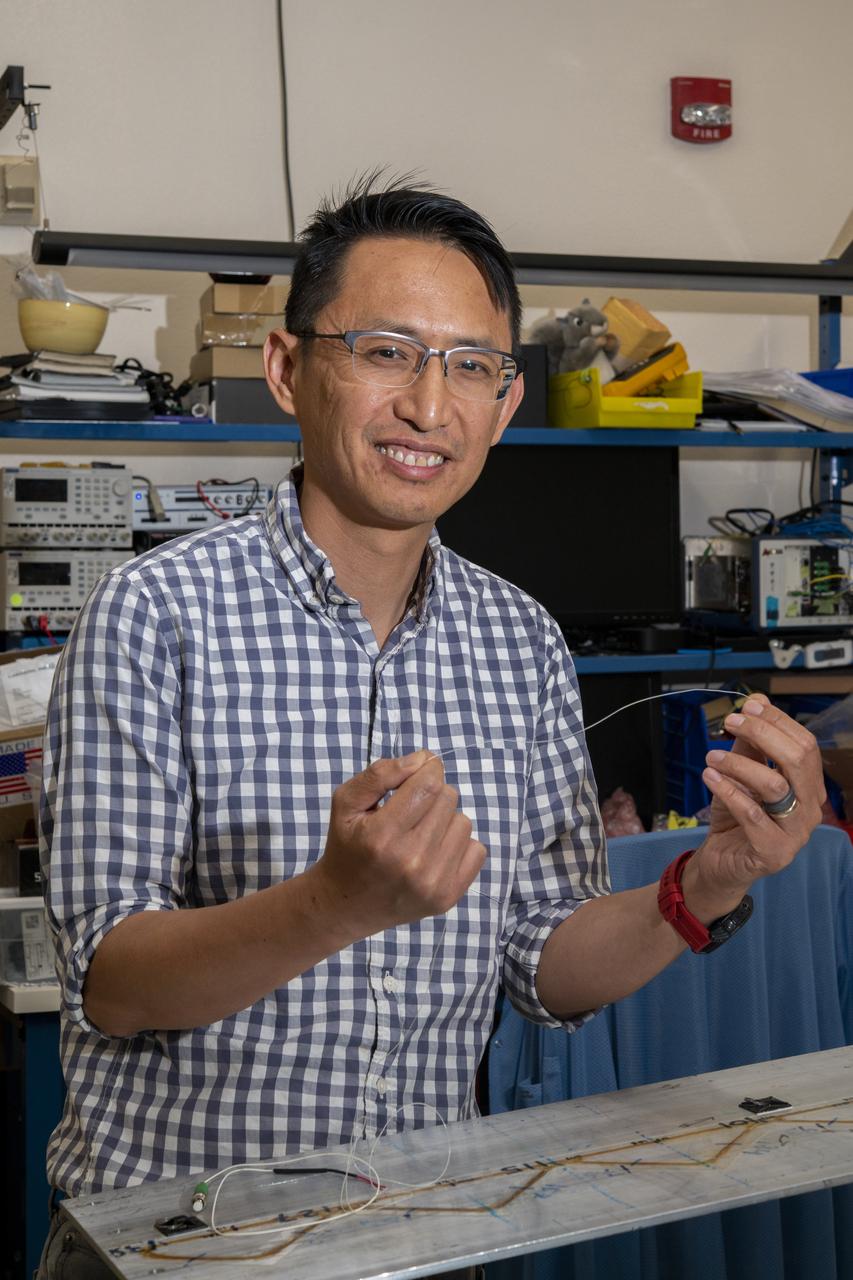
NASA’s Armstrong Flight Research Center’s FOSS, Fiber Optic Sensing System, recently supported tests of a system designed to turn oxygen into liquid oxygen, a component of rocket fuel. Patrick Chan, electronics engineer, and NASA Armstrong’s FOSS portfolio project manager, shows fiber like that used in the testing.
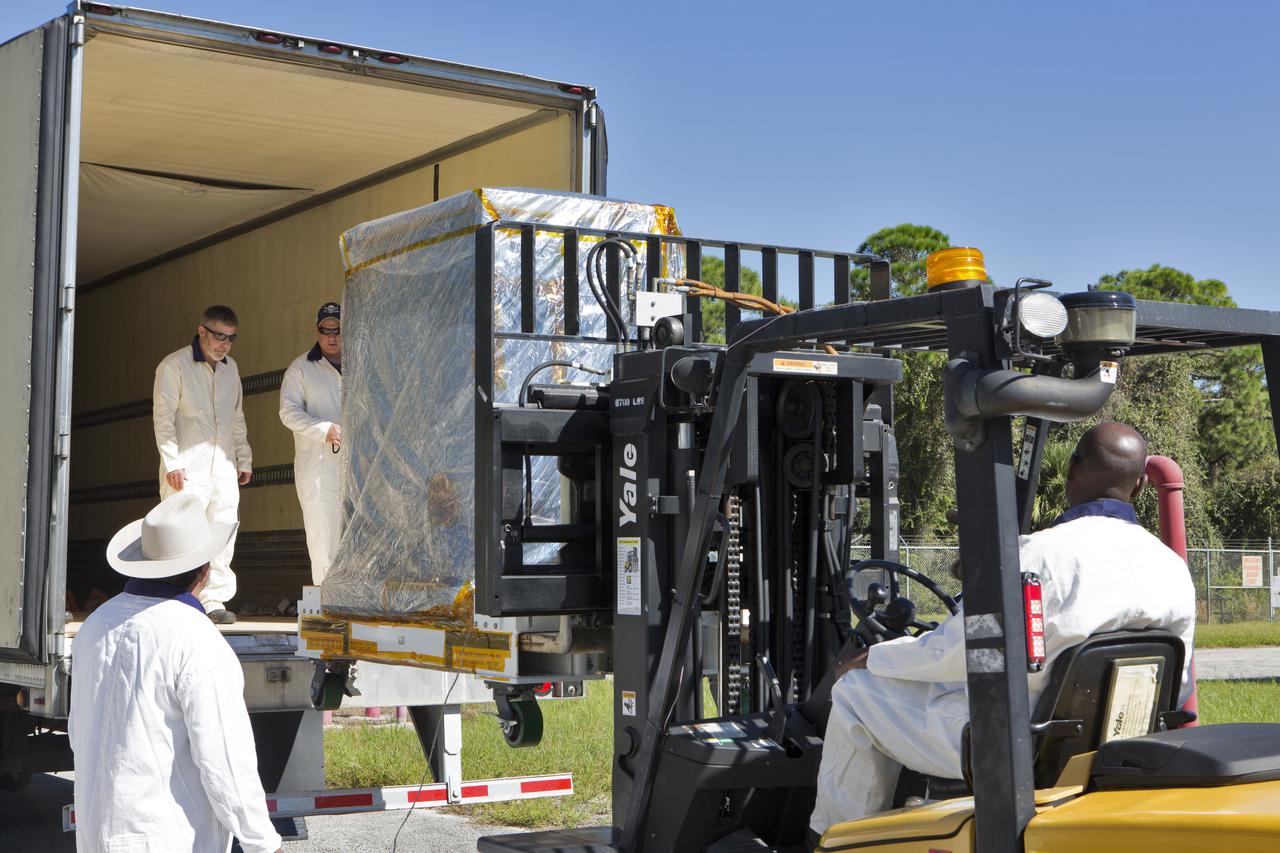
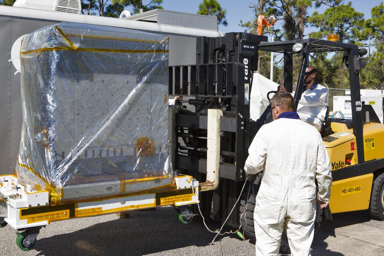
A forklift is used to load the Robotic Refueling Mission-3 (RRM3) payload onto a truck at the Fuel Transfer Building for transport to the SpaceX facility on Oct. 30, 2018, at NASA's Kennedy Space Center in Florida. The payload will be carried to the International Space Station on SpaceX's 16th Commercial Resupply Services mission. RRM3 demonstrates the transfer of xenon gas and liquid methane in microgravity, and advances technologies for storing and manipulating these cryogenic fuels robotically. RRM3 also supports development of technology for the Restore-L mission, a robotic spacecraft equipped to service satellites in-orbit.
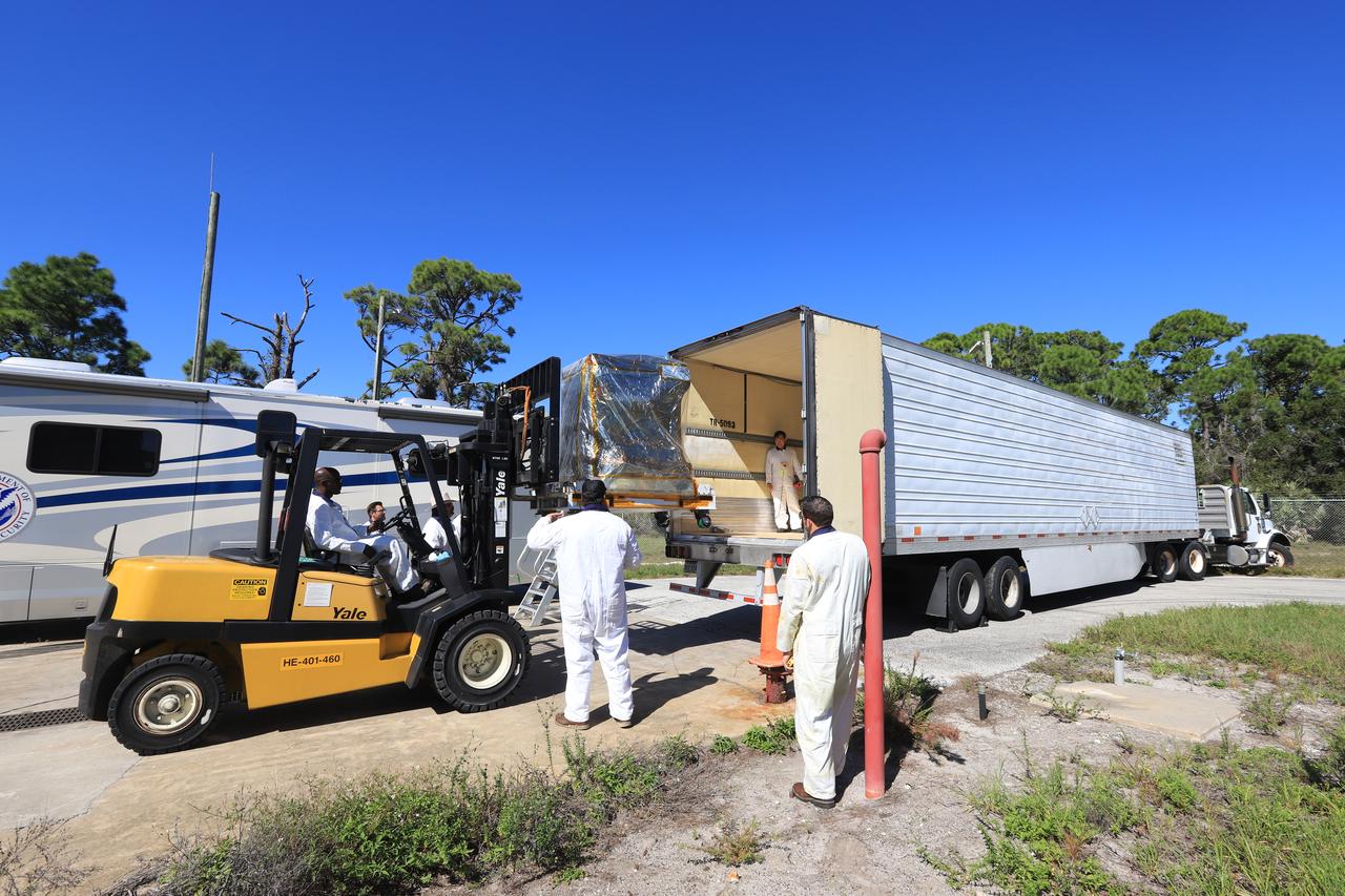
A forklift is used to load the Robotic Refueling Mission-3 (RRM3) payload onto a truck at the Fuel Transfer Building for transport to the SpaceX facility on Oct. 30, 2018, at NASA's Kennedy Space Center in Florida. The payload will be carried to the International Space Station on SpaceX's 16th Commercial Resupply Services mission. RRM3 demonstrates the transfer of xenon gas and liquid methane in microgravity, and advances technologies for storing and manipulating these cryogenic fuels robotically. RRM3 also supports development of technology for the Restore-L mission, a robotic spacecraft equipped to service satellites in-orbit.
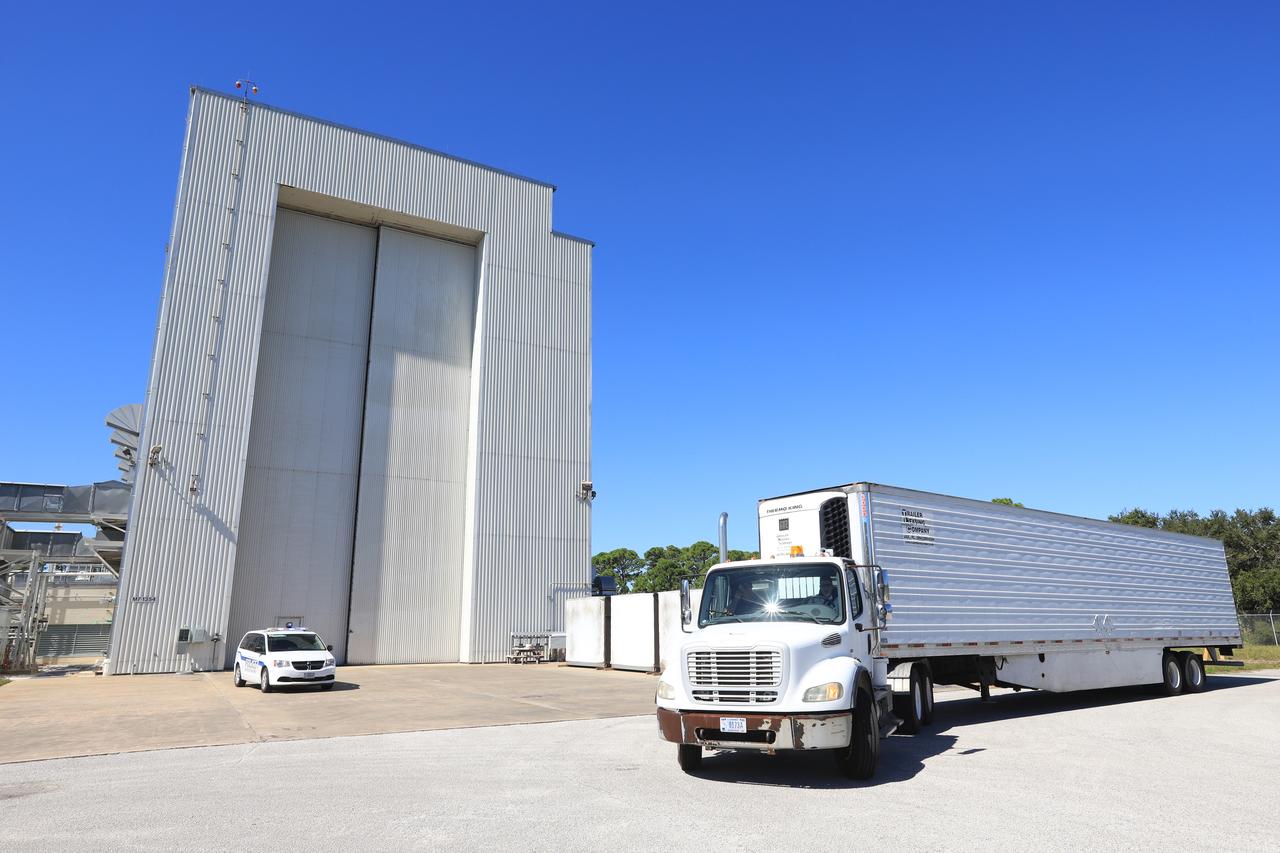
A truck containing the Robotic Refueling Mission-3 (RRM3) payload departs the Fuel Transfer Building near the Payload Hazardous Servicing Facility for transport to the SpaceX facility on Oct. 30, 2018, at NASA's Kennedy Space Center in Florida. The payload will be carried to the International Space Station on SpaceX's 16th Commercial Resupply Services mission. RRM3 demonstrates the transfer of xenon gas and liquid methane in microgravity, and advances technologies for storing and manipulating these cryogenic fuels robotically. RRM3 also supports development of technology for the Restore-L mission, a robotic spacecraft equipped to service satellites in-orbit.
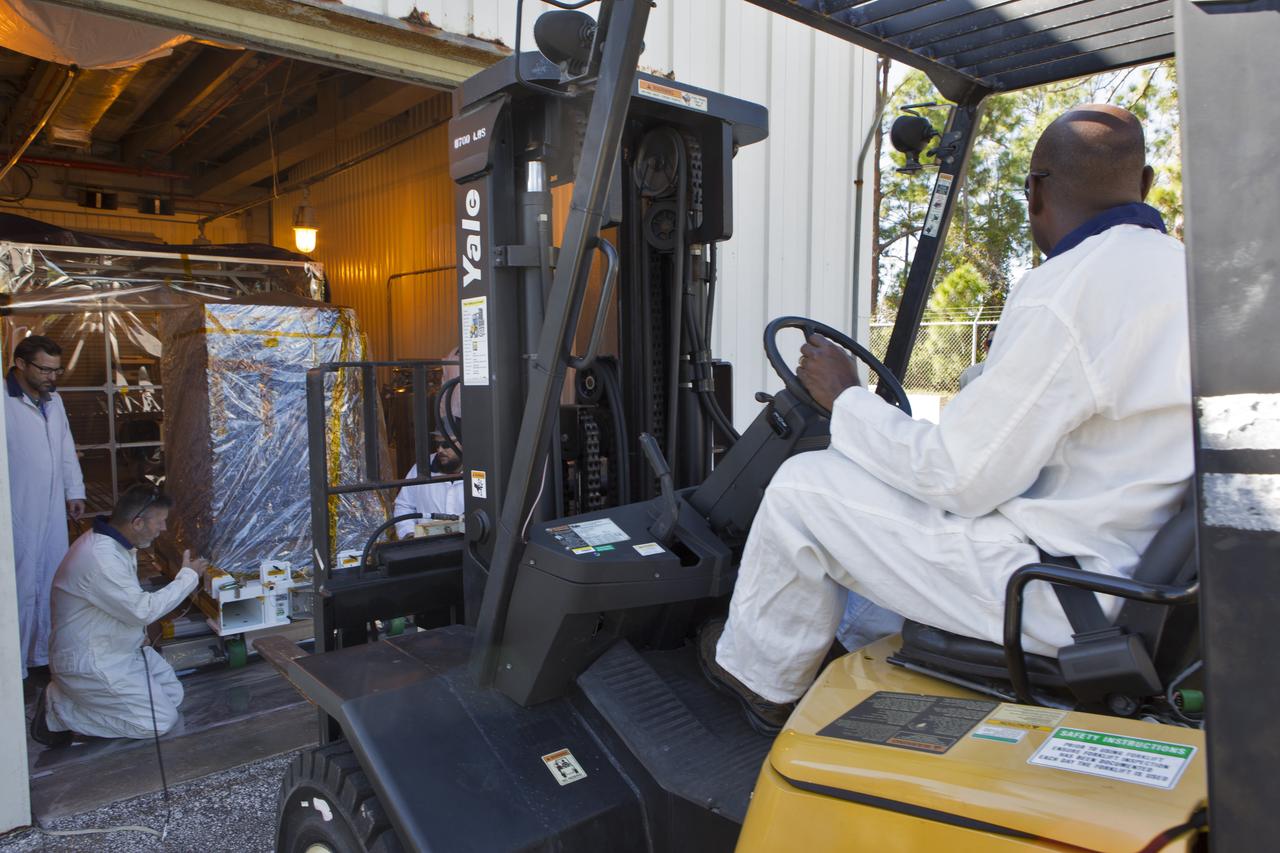
A forklift is being used to lift the Robotic Refueling Mission-3 (RRM3) payload out of the Fuel Transfer Building on Oct. 30, 2018, to be transported to the SpaceX facility at NASA's Kennedy Space Center in Florida. The payload will be carried to the International Space Station on SpaceX's 16th Commercial Resupply Services mission. RRM3 demonstrates the transfer of xenon gas and liquid methane in microgravity, and advances technologies for storing and manipulating these cryogenic fuels robotically. RRM3 also supports development of technology for the Restore-L mission, a robotic spacecraft equipped to service satellites in-orbit.
CAPE CANAVERAL, Fla. -- Inside Orbiter Processing Facility-1 at NASA’s Kennedy Space Center in Florida, technicians monitor the progress as space shuttle Discovery’s fuel cells are drained of all fluids. After all of the coolant is removed, the fuel cells will be returned to their previous location within Discovery’s mid-body. The hydrogen and oxygen dewars which feed reactants to the fuel cells remain in Discovery’s mid-body and have been purged with inert gases and vented down. The work is part of the Space Shuttle Program’s transition and retirement processing of shuttle Discovery. Discovery is being prepared for display at the Smithsonian’s National Air and Space Museum, Steven F. Udvar-Hazy Center in Chantilly, Va. For more information, visit http://www.nasa.gov/shuttle. Photo credit: NASA/Frankie Martin
CAPE CANAVERAL, Fla. – Inside Orbiter Processing Facility-1 at NASA’s Kennedy Space Center in Florida, technicians prepare to re-install the three fuel cells in space shuttle Discovery’s mid-body. The fuel cells were removed and drained of all fluids. The hydrogen and oxygen dewars which feed reactants to the fuel cells remain in Discovery’s mid-body and have been purged with inert gases and vented down. The work is part of the Space Shuttle Program’s transition and retirement processing of shuttle Discovery. Discovery is being prepared for display at the Smithsonian’s National Air and Space Museum, Steven F. Udvar-Hazy Center in Chantilly, Va. For more information, visit http://www.nasa.gov/shuttle. Photo credit: NASA/Dimitri Gerondidakis
CAPE CANAVERAL, Fla. -- Inside Orbiter Processing Facility-1 at NASA’s Kennedy Space Center in Florida, technicians prepare space shuttle Discovery’s three fuel cells to be drained of all fluids. After all of the coolant is removed, the fuel cells will be returned to their previous location within Discovery’s mid-body. The hydrogen and oxygen dewars which feed reactants to the fuel cells remain in Discovery’s mid-body and have been purged with inert gases and vented down. The work is part of the Space Shuttle Program’s transition and retirement processing of shuttle Discovery. Discovery is being prepared for display at the Smithsonian’s National Air and Space Museum, Steven F. Udvar-Hazy Center in Chantilly, Va. For more information, visit http://www.nasa.gov/shuttle. Photo credit: NASA/Frankie Martin
CAPE CANAVERAL, Fla. -- Inside Orbiter Processing Facility-1 at NASA’s Kennedy Space Center in Florida, a technician prepares one of space shuttle Discovery’s three fuel cells to be drained of all fluids. After all of the coolant is removed, the fuel cells will be returned to their previous location within Discovery’s mid-body. The hydrogen and oxygen dewars which feed reactants to the fuel cells remain in Discovery’s mid-body and have been purged with inert gases and vented down. The work is part of the Space Shuttle Program’s transition and retirement processing of shuttle Discovery. Discovery is being prepared for display at the Smithsonian’s National Air and Space Museum, Steven F. Udvar-Hazy Center in Chantilly, Va. For more information, visit http://www.nasa.gov/shuttle. Photo credit: NASA/Frankie Martin

CAPE CANAVERAL, Fla. – Inside Orbiter Processing Facility-1 at NASA’s Kennedy Space Center in Florida, technicians prepare to re-install the three fuel cells in space shuttle Discovery’s mid-body. The fuel cells were removed and drained of all fluids. The hydrogen and oxygen dewars which feed reactants to the fuel cells remain in Discovery’s mid-body and have been purged with inert gases and vented down. The work is part of the Space Shuttle Program’s transition and retirement processing of shuttle Discovery. Discovery is being prepared for display at the Smithsonian’s National Air and Space Museum, Steven F. Udvar-Hazy Center in Chantilly, Va. For more information, visit http://www.nasa.gov/shuttle. Photo credit: NASA/Dimitri Gerondidakis
CAPE CANAVERAL, Fla. – Inside Orbiter Processing Facility-1 at NASA’s Kennedy Space Center in Florida, technicians re-install the three fuel cells in space shuttle Discovery’s mid-body. The fuel cells were removed and drained of all fluids. The hydrogen and oxygen dewars which feed reactants to the fuel cells remain in Discovery’s mid-body and have been purged with inert gases and vented down. The work is part of the Space Shuttle Program’s transition and retirement processing of shuttle Discovery. Discovery is being prepared for display at the Smithsonian’s National Air and Space Museum, Steven F. Udvar-Hazy Center in Chantilly, Va. For more information, visit http://www.nasa.gov/shuttle. Photo credit: NASA/Dimitri Gerondidakis
CAPE CANAVERAL, Fla. – Inside Orbiter Processing Facility-1 at NASA’s Kennedy Space Center in Florida, technicians re-install the three fuel cells in space shuttle Discovery’s mid-body. The fuel cells were removed and drained of all fluids. The hydrogen and oxygen dewars which feed reactants to the fuel cells remain in Discovery’s mid-body and have been purged with inert gases and vented down. The work is part of the Space Shuttle Program’s transition and retirement processing of shuttle Discovery. Discovery is being prepared for display at the Smithsonian’s National Air and Space Museum, Steven F. Udvar-Hazy Center in Chantilly, Va. For more information, visit http://www.nasa.gov/shuttle. Photo credit: NASA/Dimitri Gerondidakis
CAPE CANAVERAL, Fla. -- Inside Orbiter Processing Facility-1 at NASA’s Kennedy Space Center in Florida, technicians monitor the progress as space shuttle Discovery’s fuel cells are drained of all fluids. After all of the coolant is removed, the fuel cells will be returned to their previous location within Discovery’s mid-body. The hydrogen and oxygen dewars which feed reactants to the fuel cells remain in Discovery’s mid-body and have been purged with inert gases and vented down. The work is part of the Space Shuttle Program’s transition and retirement processing of shuttle Discovery. Discovery is being prepared for display at the Smithsonian’s National Air and Space Museum, Steven F. Udvar-Hazy Center in Chantilly, Va. For more information, visit http://www.nasa.gov/shuttle. Photo credit: NASA/Frankie Martin
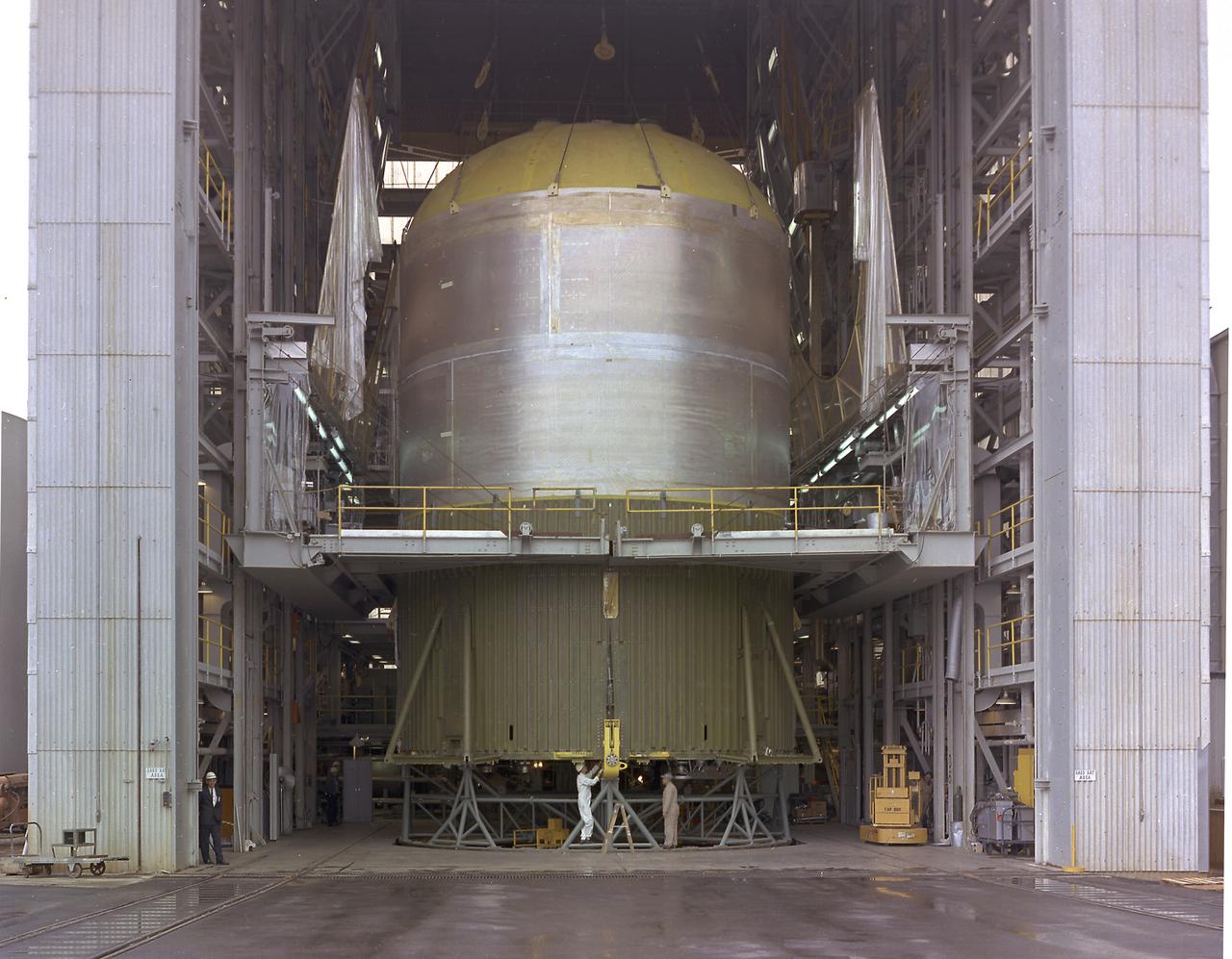
This photograph shows the Saturn V assembled LOX (Liquid Oxygen) and fuel tanks ready for transport from the Manufacturing Engineering Laboratory at Marshall Space Flight Center in Huntsville, Alabama. The tanks were then shipped to the launch site at Kennedy Space Center for a flight. The towering 363-foot Saturn V was a multi-stage, multi-engine launch vehicle standing taller than the Statue of Liberty. Altogether, the Saturn V engines produced as much power as 85 Hoover Dams.
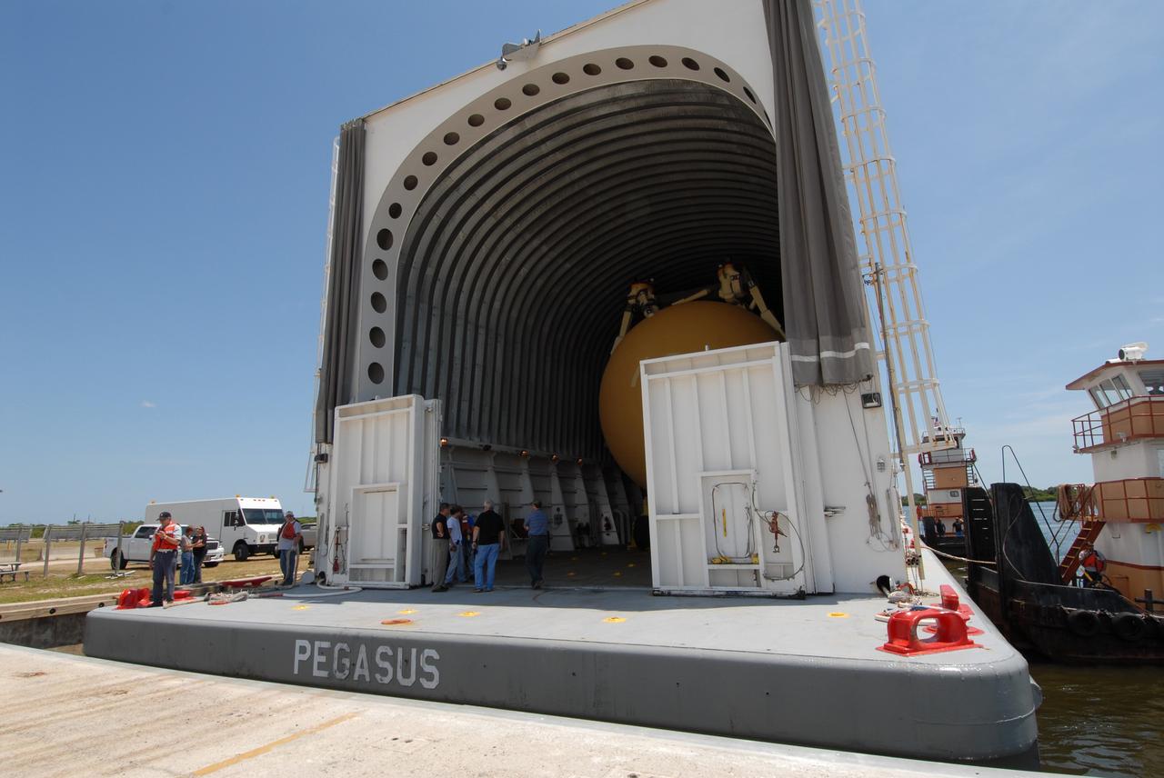
CAPE CANAVERAL, Fla. – The Pegasus barge is docked in the turn basin in the Launch Complex 39 Area at NASA's Kennedy Space Center in Florida. Inside is the external fuel tank, ET- 132, designated for space shuttle Discovery on the STS-128 mission. The tank will be offloaded and transported to a high bay in the Vehicle Assembly Building for checkout. On the STS-128 mission, Discovery will carry science and storage racks to the International Space Station. Launch of Discovery is targeted for Aug. 6. Photo credit: NASA/Troy Cryder
This image shows the Saturn V S-IC-T stage (S-IC static test article) fuel tank being attached to the thrust structure in the vehicle assembly building at the Marshall Space Flight Center (MSFC). The S-IC stage utilized five F-1 engines that used liquid oxygen and kerosene as propellant and provided a combined thrust of 7,500,000 pounds.
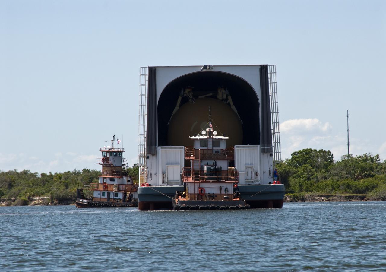
CAPE CANAVERAL, Fla. – Tugboats maneuver the Pegasus barge toward the dock in the turn basin in the Launch Complex 39 Area at NASA's Kennedy Space Center in Florida. The barge holds the external fuel tank, ET- 132, designated for space shuttle Discovery on the STS-128 mission. The tank will be offloaded and transported to a high bay in the Vehicle Assembly Building for checkout. On the STS-128 mission, Discovery will carry science and storage racks to the International Space Station. Launch of Discovery is targeted for Aug. 6. Photo credit: NASA/Troy Cryder
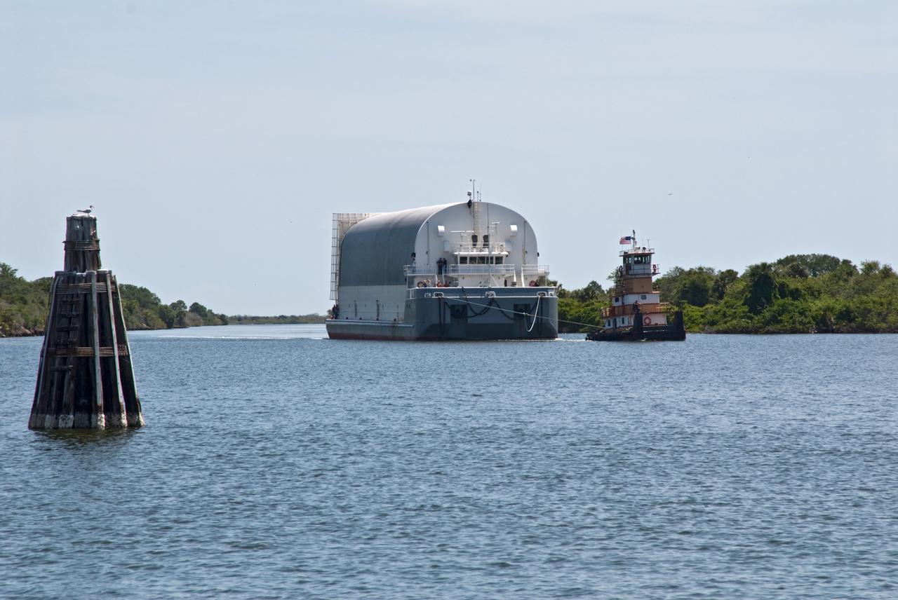
CAPE CANAVERAL, Fla. – The Pegasus barge, towed by a tugboat, enters the turn basin in the Launch Complex 39 Area at NASA's Kennedy Space Center in Florida. The barge holds the external fuel tank, ET- 132, designated for space shuttle Discovery on the STS-128 mission. The tank will be offloaded and transported to a high bay in the Vehicle Assembly Building for checkout. On the STS-128 mission, Discovery will carry science and storage racks to the International Space Station. Launch of Discovery is targeted for Aug. 6. Photo credit: NASA/Troy Cryder
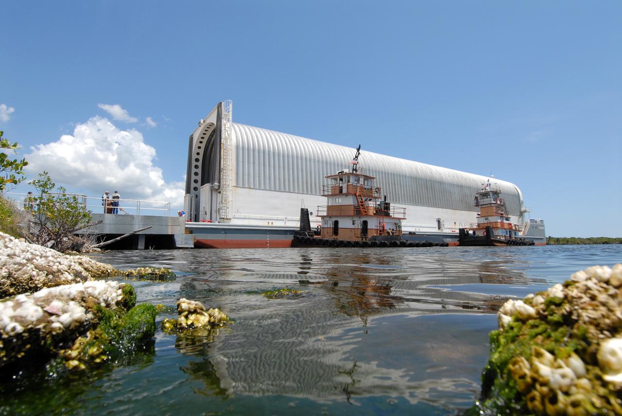
CAPE CANAVERAL, Fla. – The Pegasus barge is docked in the turn basin in the Launch Complex 39 Area at NASA's Kennedy Space Center in Florida. Inside is the external fuel tank, ET- 132, designated for space shuttle Discovery on the STS-128 mission. The tank will be offloaded and transported to a high bay in the Vehicle Assembly Building for checkout. On the STS-128 mission, Discovery will carry science and storage racks to the International Space Station. Launch of Discovery is targeted for Aug. 6. Photo credit: NASA/Troy Cryder