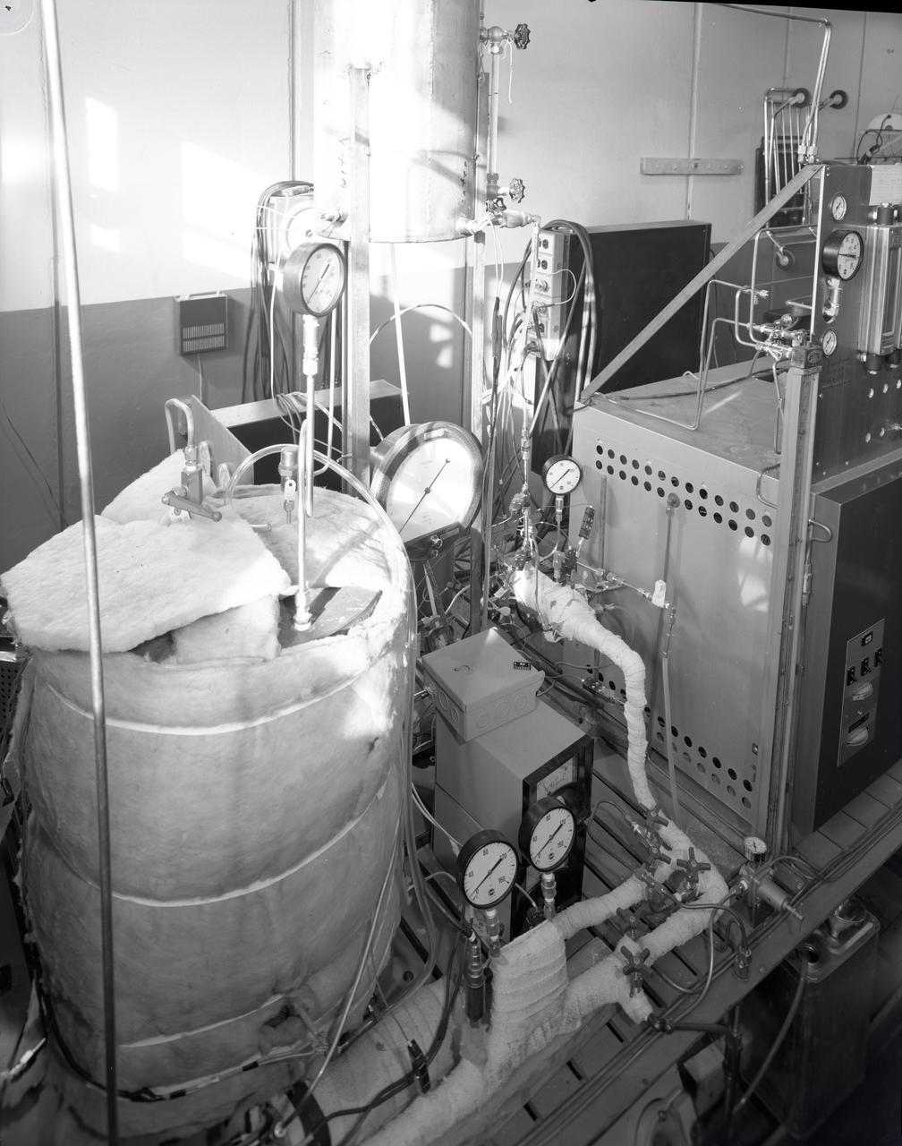
FUEL CELL CONDENSER FOR THE APOLLO SYSTEM TEST RIG
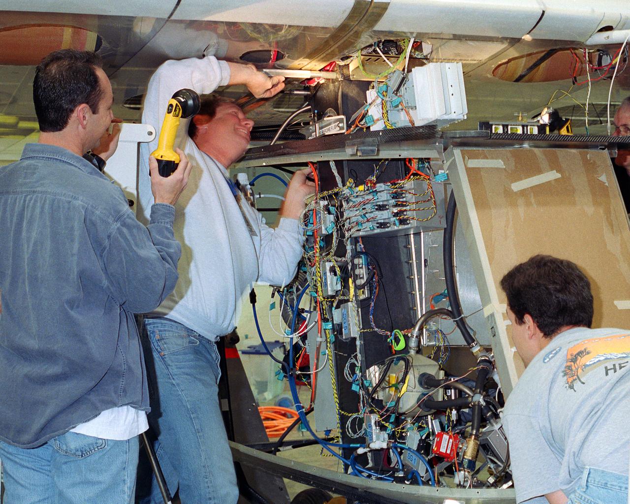
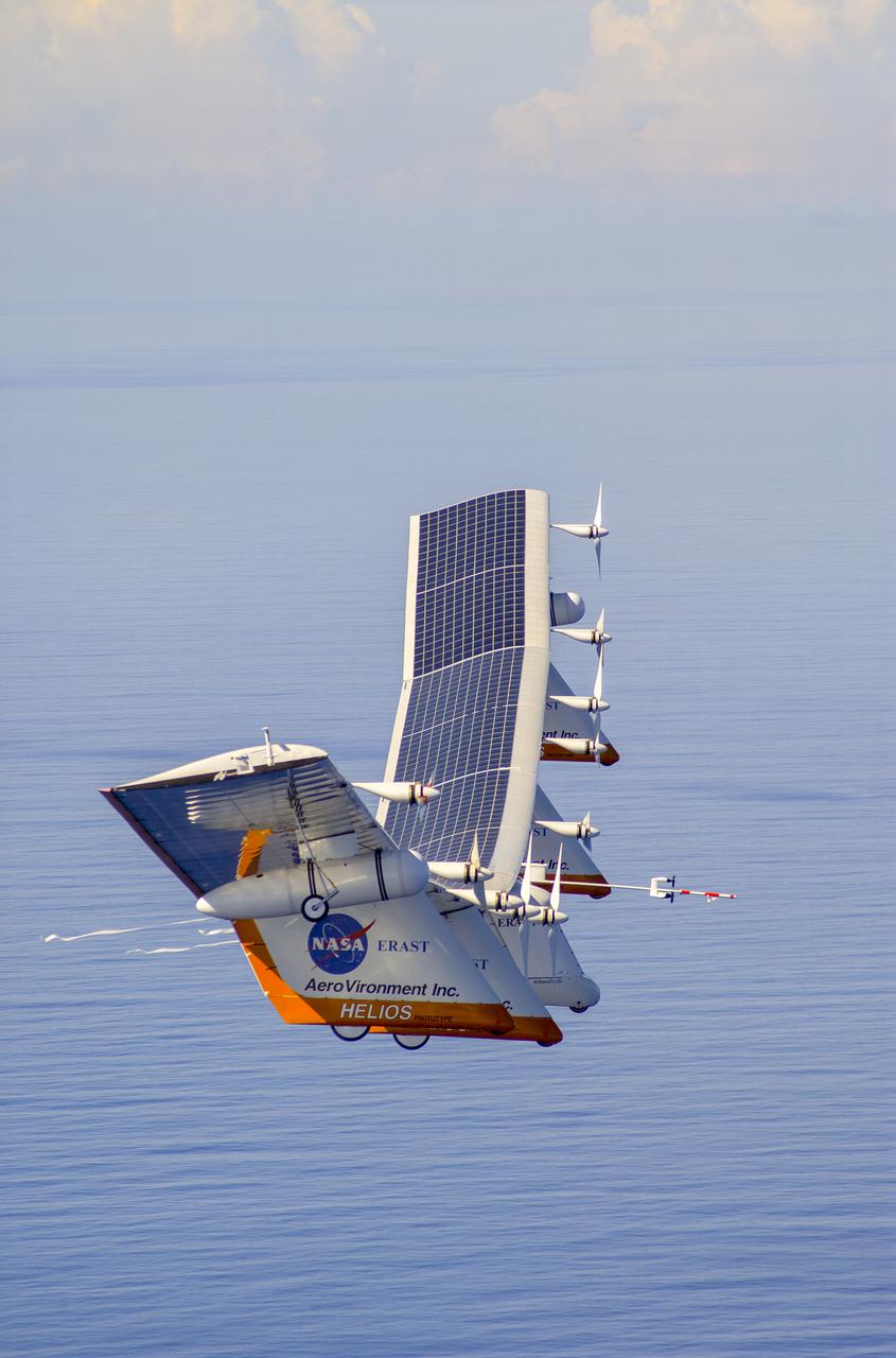
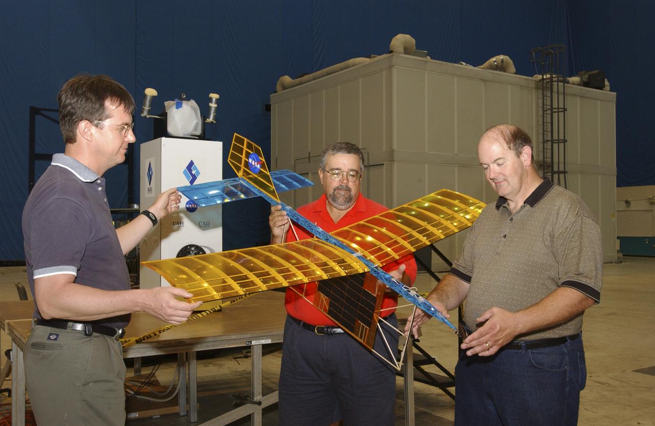
Aerovironment technicians carefully line up attachments as a fuel cell electrical system is installed on the Helios Prototype solar powered flying wing. The fuel cell system will power the aircraft at night during NASA-sponsored long-endurance demonstration flight in the summer of 2003.
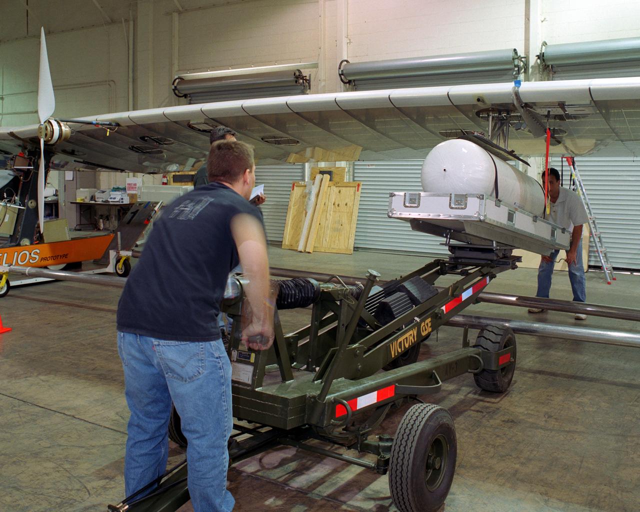
Technicians for AeroVironment, Inc., jack up a pressure tank to the wing of the Helios Prototype solar-electric flying wing. The tank carries pressurized hydrogen to fuel an experimental fuel cell system that powered the aircraft at night during an almost two-day long-endurance flight demonstration in the summer of 2003.
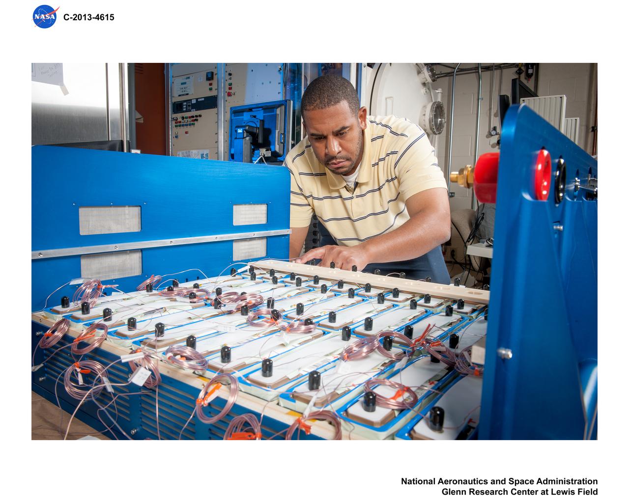
Advanced Exploration Systems (AES) Modular Power Systems for Space Exploration (AMPS); electrochemistry, AMPS, will infuse and demonstrate batteries, fuel cells, and other power modules for exploration ground system demonstrations
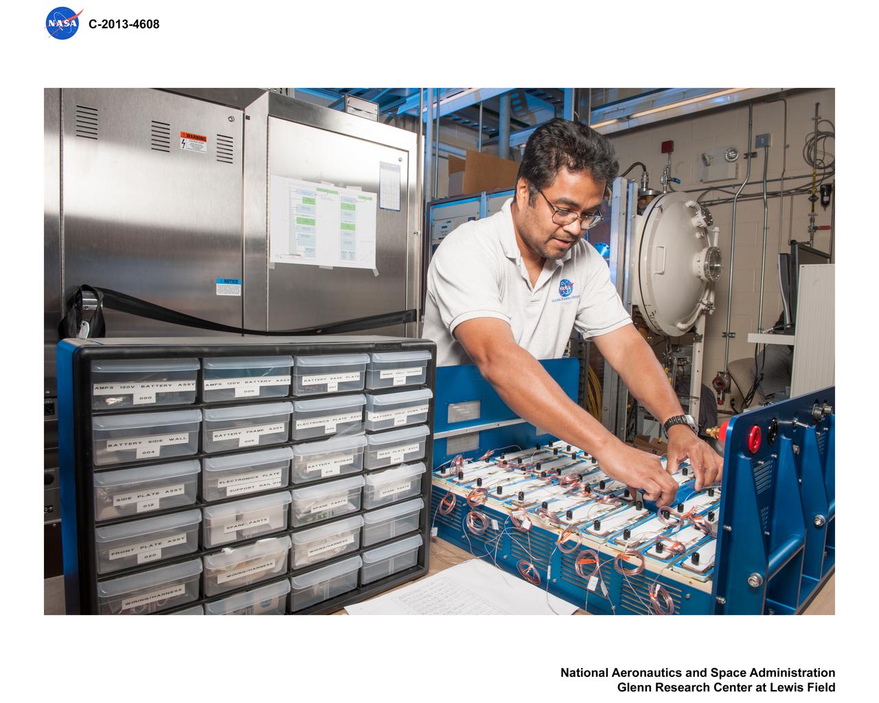
Advanced Exploration Systems (AES) Modular Power Systems for Space Exploration (AMPS); electrochemistry, AMPS, will infuse and demonstrate batteries, fuel cells, and other power modules for exploration ground system demonstrations
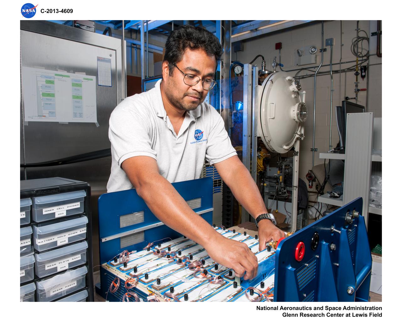
Advanced Exploration Systems (AES) Modular Power Systems for Space Exploration (AMPS); electrochemistry, AMPS, will infuse and demonstrate batteries, fuel cells, and other power modules for exploration ground system demonstrations
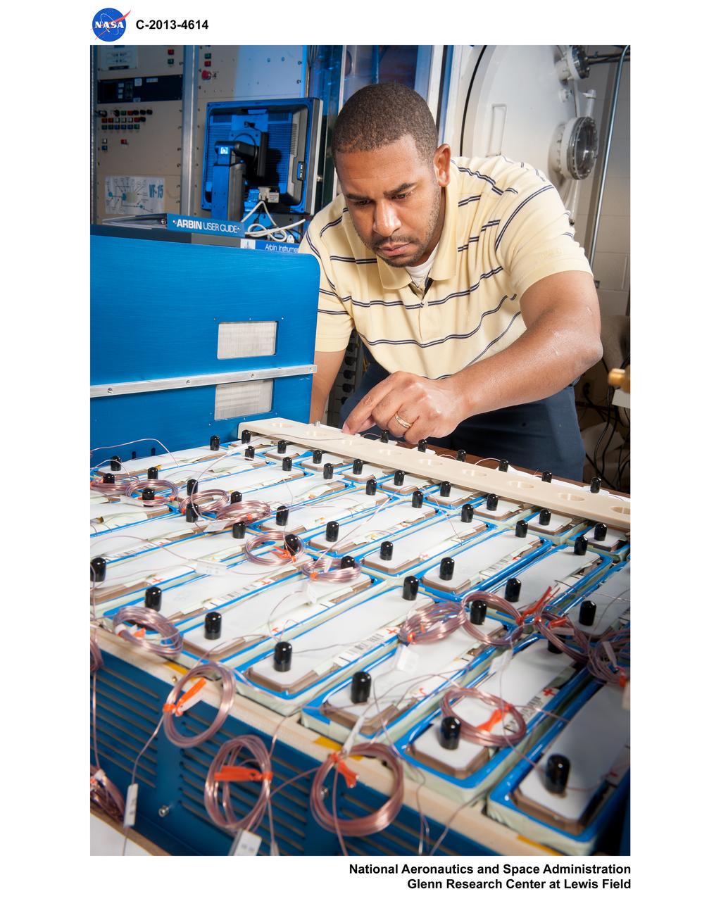
Advanced Exploration Systems (AES) Modular Power Systems for Space Exploration (AMPS); electrochemistry, AMPS, will infuse and demonstrate batteries, fuel cells, and other power modules for exploration ground system demonstrations
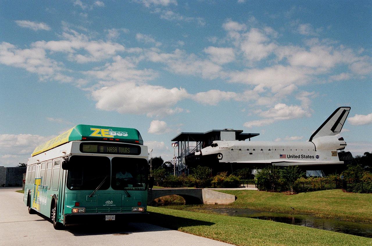
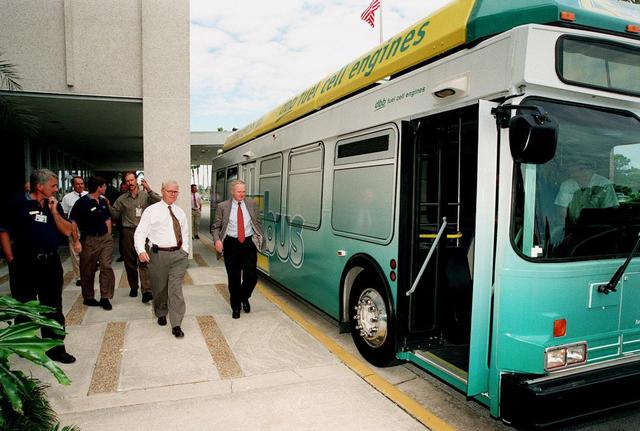
The Zero Emissions (ZE) transit bus passes a mock-up orbiter named Explorer on a trek through the KSC Visitor Complex. Provided by dbb fuel cell engines inc. of Vancouver, Canada, the ZE bus was brought to KSC as part of the Center's Alternative Fuel Initiatives Program. The bus uses a Proton Exchange Membrane fuel cell in which hydrogen and oxygen, from atmospheric air, react to produce electricity that powers an electric motor drive system. The by-product "exhaust" from the fuel cell is water vapor, thus zero harmful emissions. A typical diesel-powered bus emits more than a ton of harmful pollutants from its exhaust every year. The ZE bus is being used on tour routes at the KSC Visitor Complex for two days to introduce the public to the concept
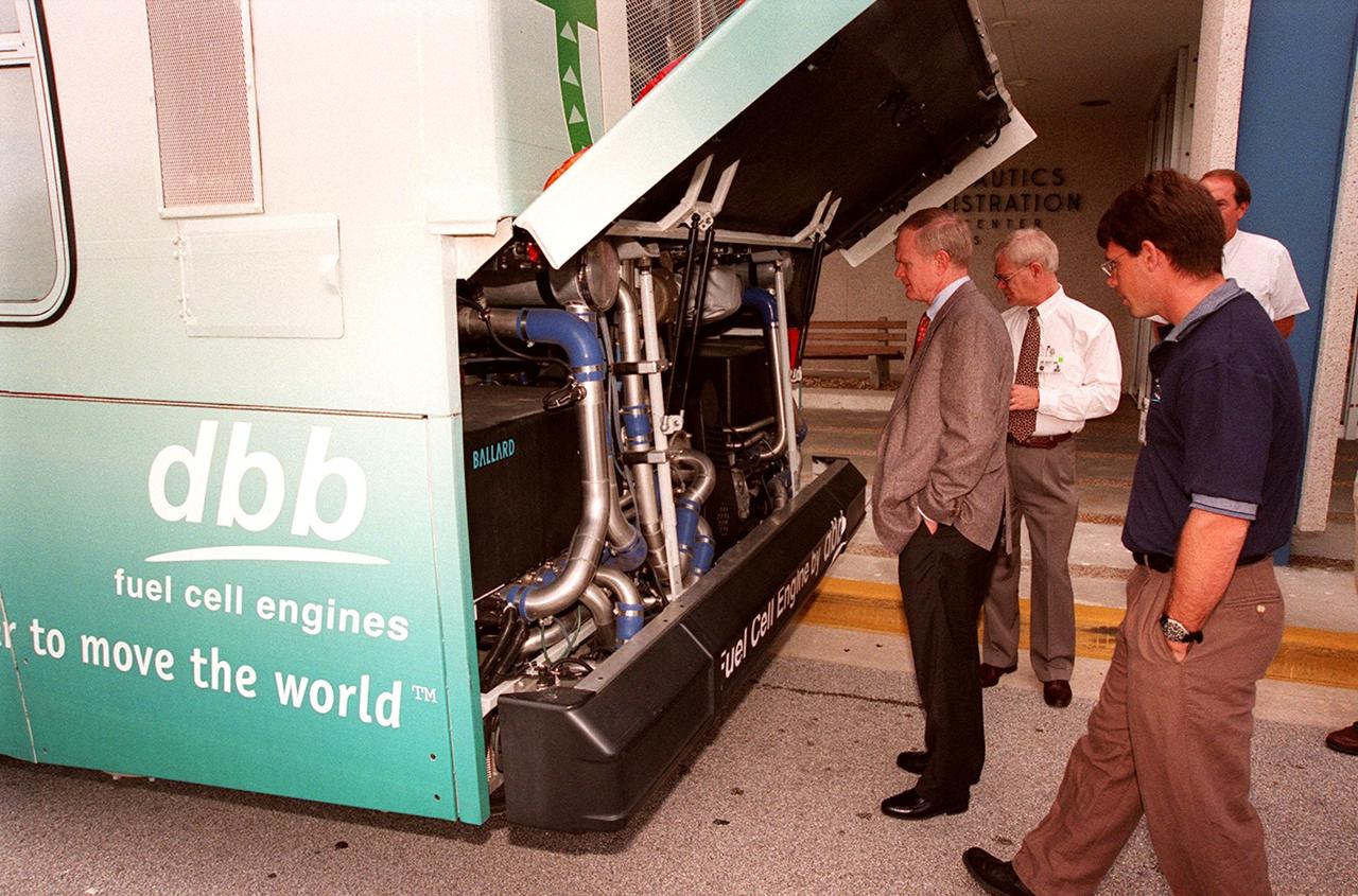
In front of the Headquarters Building at KSC, Center Director Roy Bridges (left) looks at the hydrogen-oxygen driven engine powering a Zero Emissions (ZE) transit bus. Provided by dbb fuel cell engines inc. of Vancouver, Canada, the ZE bus was brought to KSC as part of the Center's Alternative Fuel Initiatives Program. The bus uses a Proton Exchange Membrane fuel cell in which hydrogen and oxygen, from atmospheric air, react to produce electricity that powers an electric motor drive system. The by-product "exhaust" from the fuel cell is water vapor, thus zero harmful emissions. A typical diesel-powered bus emits more than a ton of harmful pollutants from its exhaust every year. Available for viewing by employees, the ZE bus is also being used on tour routes at the KSC Visitor Complex Oct. 26-27
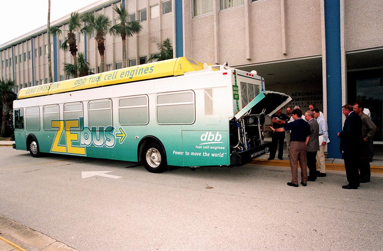
On view in front of the Headquarters Building, the Zero Emissions (ZE) transit bus attracts an interested group of employees, including Center Director Roy Bridges (second from left in foreground). Provided by dbb fuel cell engines inc. of Vancouver, Canada, the ZE bus was brought to KSC as part of the Center's Alternative Fuel Initiatives Program. The bus uses a Proton Exchange Membrane fuel cell in which hydrogen and oxygen, from atmospheric air, react to produce electricity that powers an electric motor drive system. The by-product "exhaust" from the fuel cell is water vapor, thus zero harmful emissions. A typical diesel-powered bus emits more than a ton of harmful pollutants from its exhaust every year. Available for viewing by employees, the ZE bus is also being used on tour routes at the KSC Visitor Complex Oct. 26-27
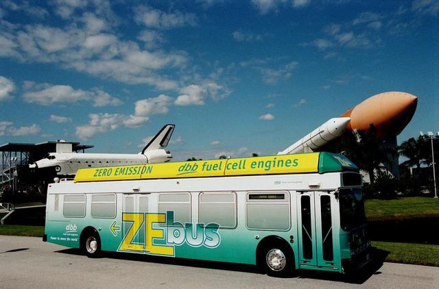
The Zero Emissions (ZE) transit bus tours the KSC Visitor Complex for a test ride. In the background are a mock-up orbiter named Explorer (left) and a stack of solid rocket boosters and external tank (right), typically used on Shuttle launches. Provided by dbb fuel cell engines inc. of Vancouver, Canada, the ZE bus was brought to KSC as part of the Center's Alternative Fuel Initiatives Program. The bus uses a Proton Exchange Membrane fuel cell in which hydrogen and oxygen, from atmospheric air, react to produce electricity that powers an electric motor drive system. The by-product "exhaust" from the fuel cell is water vapor, thus zero harmful emissions. A typical diesel-powered bus emits more than a ton of harmful pollutants from its exhaust every year. The ZE bus is being used on tour routes at the KSC Visitor Complex for two days to introduce the public to the concept
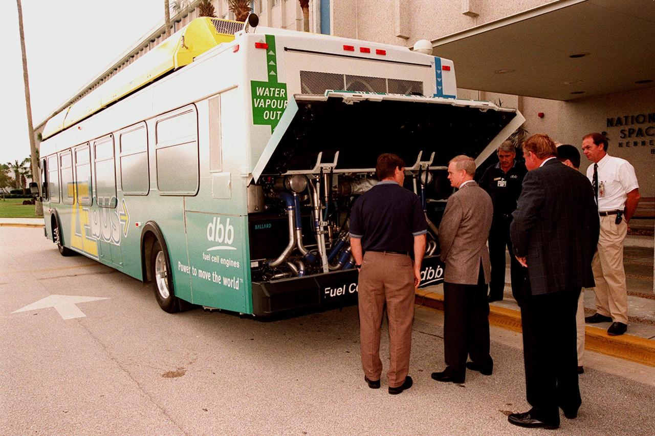
KSC employees, along with Center Director Roy Bridges (second from left), view the hydrogen-oxygen driven engine powering a Zero Emissions (ZE) transit bus. Provided by dbb fuel cell engines inc. of Vancouver, Canada, the ZE bus was brought to KSC as part of the Center's Alternative Fuel Initiatives Program. The bus uses a Proton Exchange Membrane fuel cell in which hydrogen and oxygen, from atmospheric air, react to produce electricity that powers an electric motor drive system. The by-product "exhaust" from the fuel cell is water vapor, thus zero harmful emissions. A typical diesel-powered bus emits more than a ton of harmful pollutants from its exhaust every year. Available for viewing by employees, the ZE bus is also being used on tour routes at the KSC Visitor Complex Oct. 26-27
KSC workers, with Center Director Roy Bridges (at right next to bus), head for the open door of the Zero Emissions (ZE) transit bus and a ride around the center. Provided by dbb fuel cell engines inc. of Vancouver, Canada, the ZE bus was brought to KSC as part of the Center's Alternative Fuel Initiatives Program. The bus uses a Proton Exchange Membrane fuel cell in which hydrogen and oxygen, from atmospheric air, react to produce electricity that powers an electric motor drive system. The by-product "exhaust" from the fuel cell is water vapor, thus zero harmful emissions. A typical diesel-powered bus emits more than a ton of harmful pollutants from its exhaust every year. Available to employees for viewing and a ride, the ZE bus is also being used on tour routes at the KSC Visitor Complex Oct. 26-27
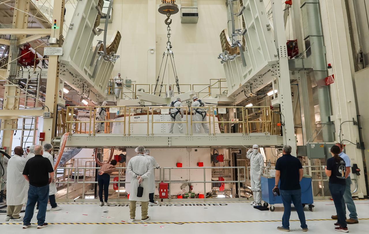
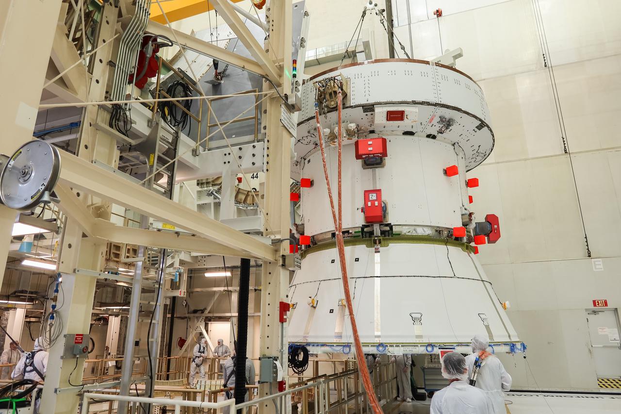
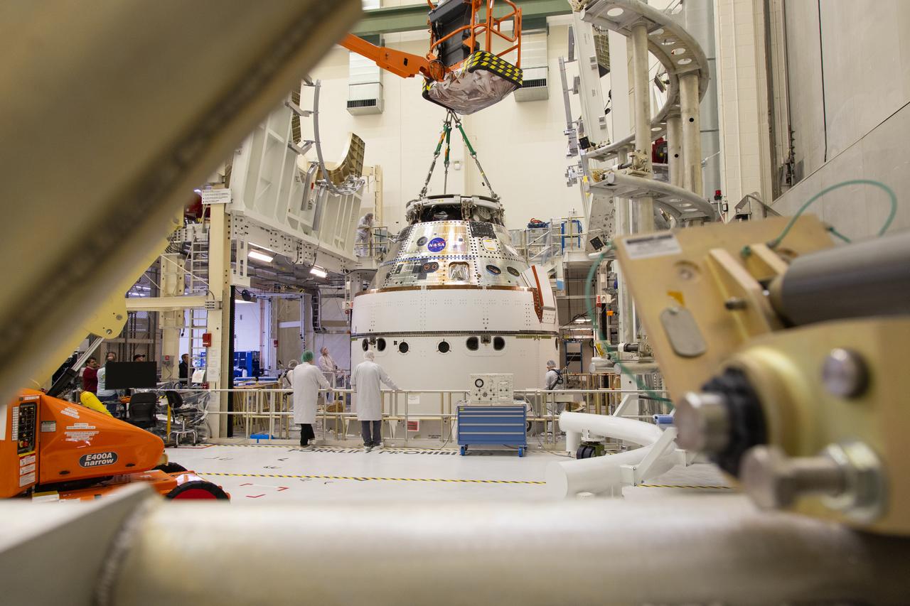
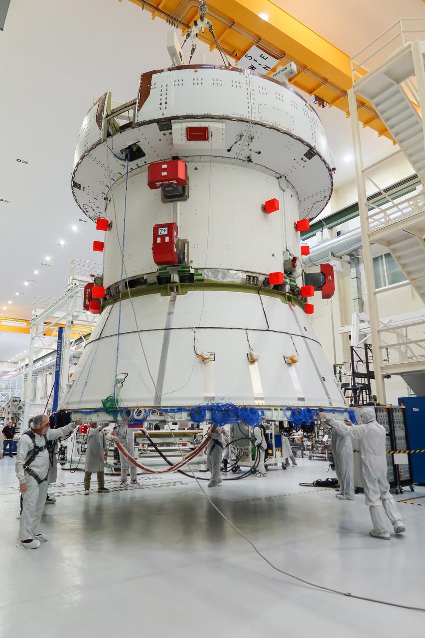
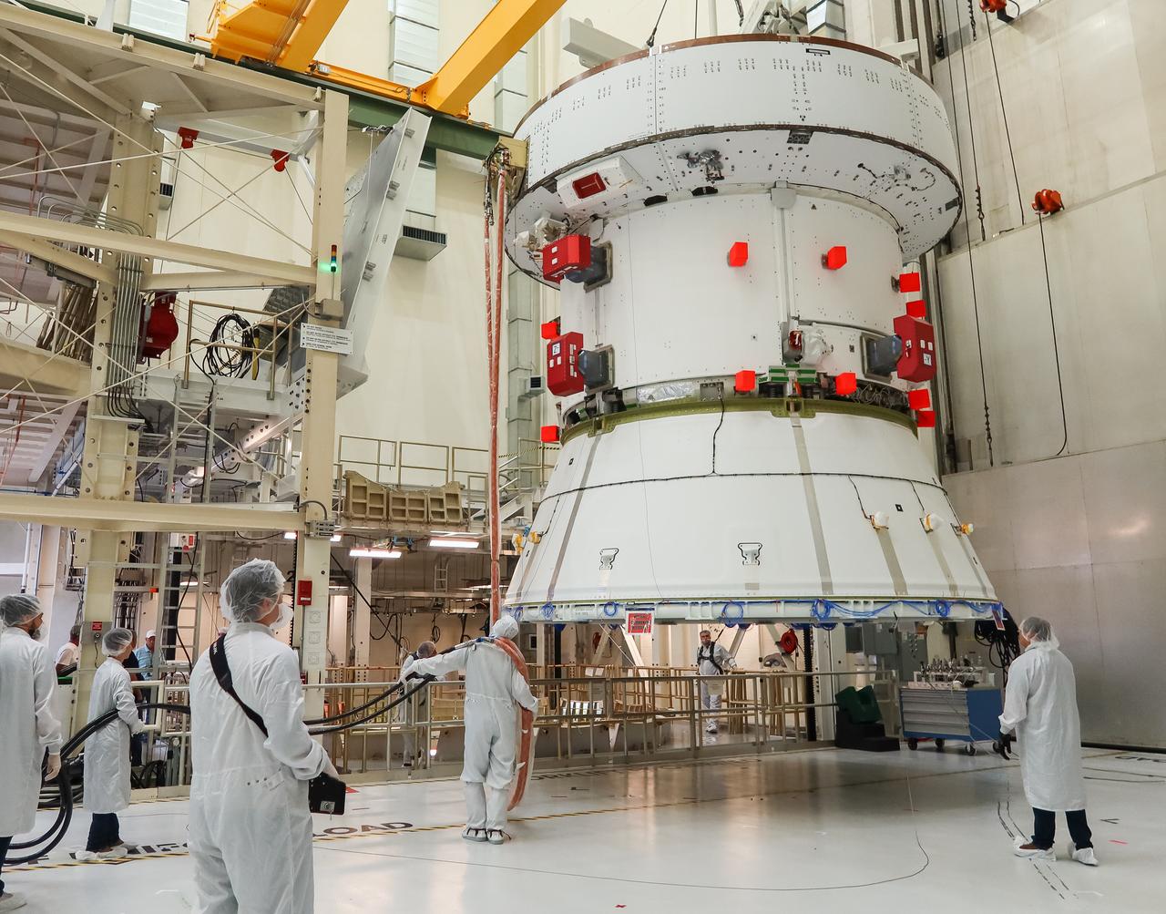
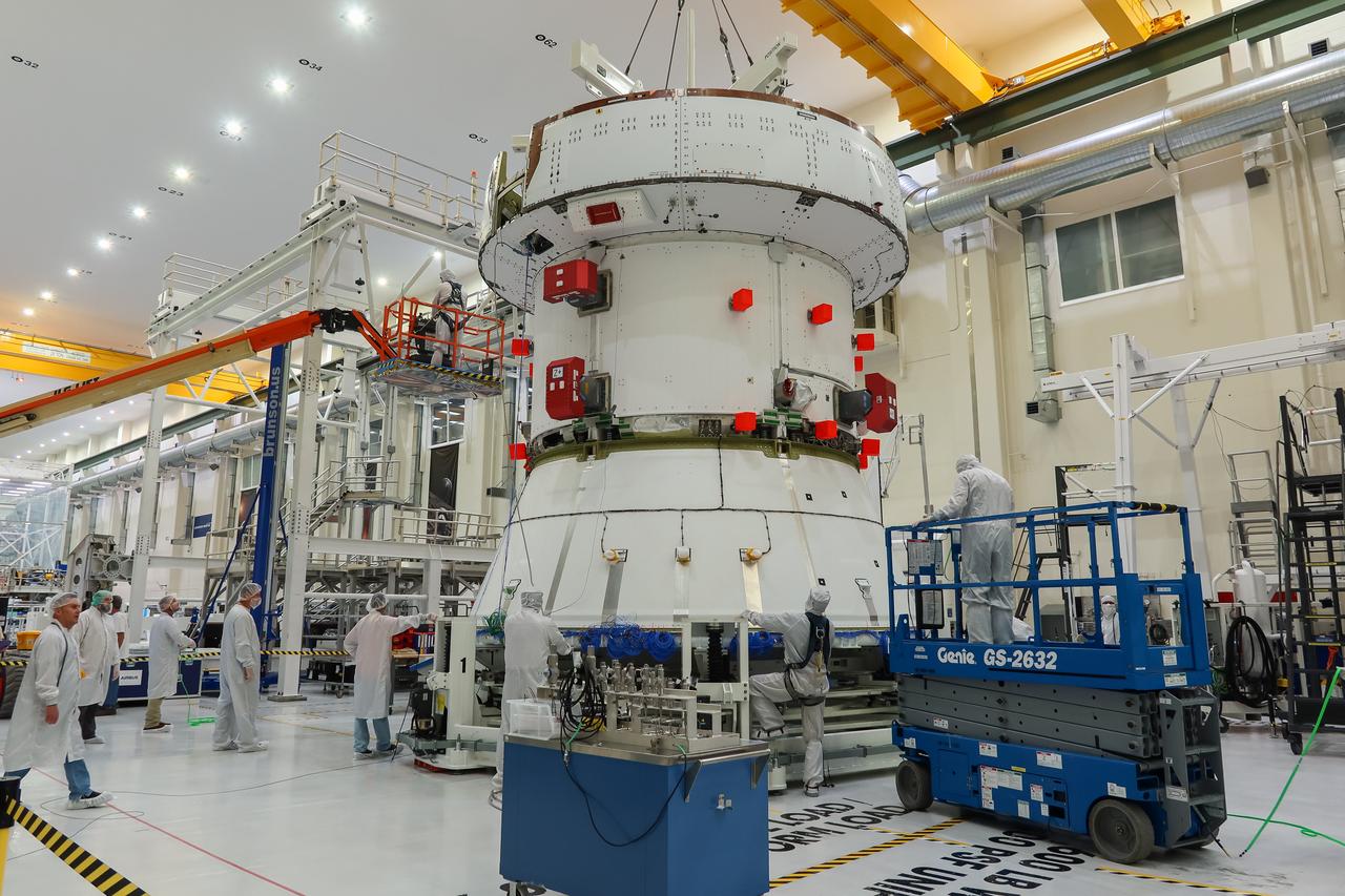
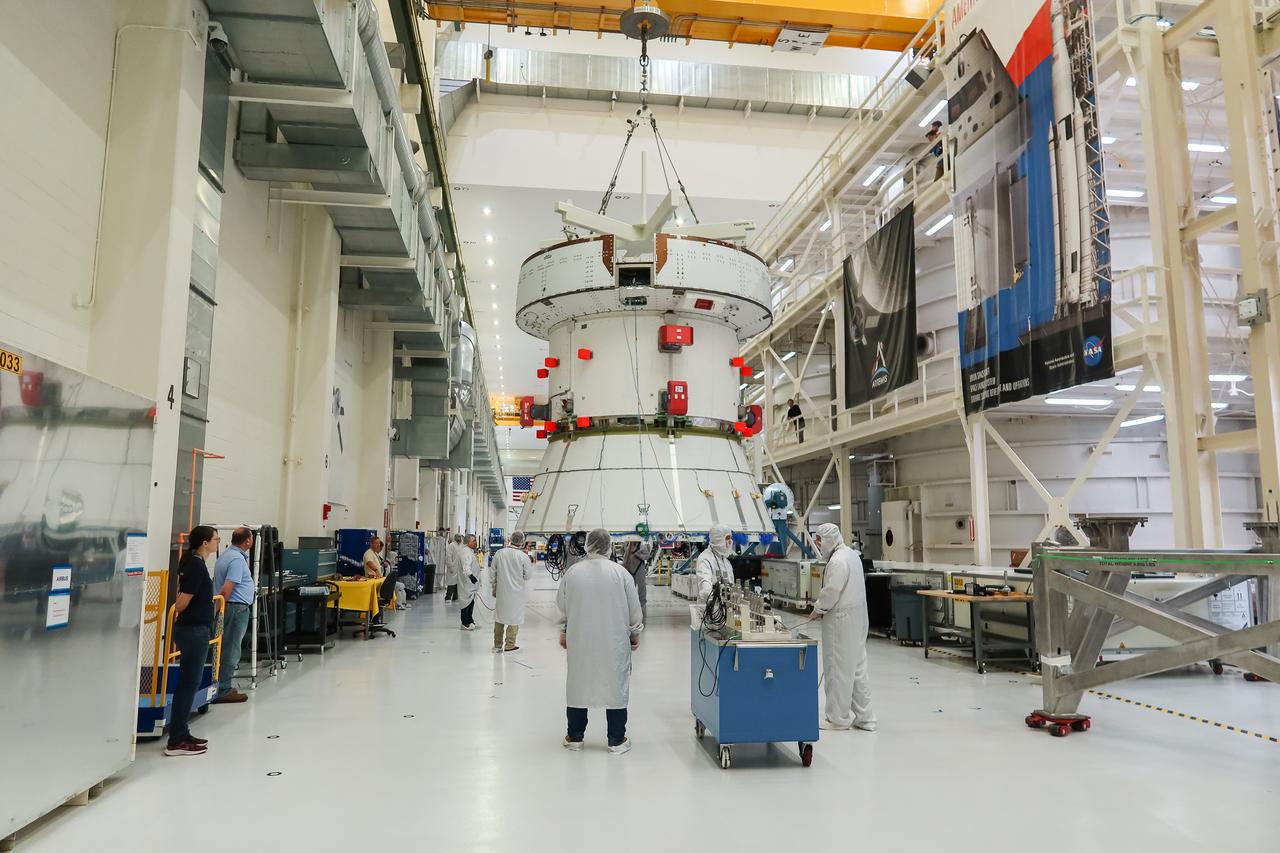
The European Service Module (ESM) for NASA’s Artemis II mission is secured inside the FAST (final assembly and system testing) cell in the high bay of the Neil A. Armstrong Operations and Checkout Building at NASA’s Kennedy Space Center in Florida on May 22, 2023. The ESM is in the FAST cell for final checkouts before it is stacked with the Orion crew module. Technicians are removing the crane that was used to move the ESM. The powerhouse that will fuel and propel Orion in space, the ESM will be used for Artemis II, the first Artemis mission flying crew aboard Orion.
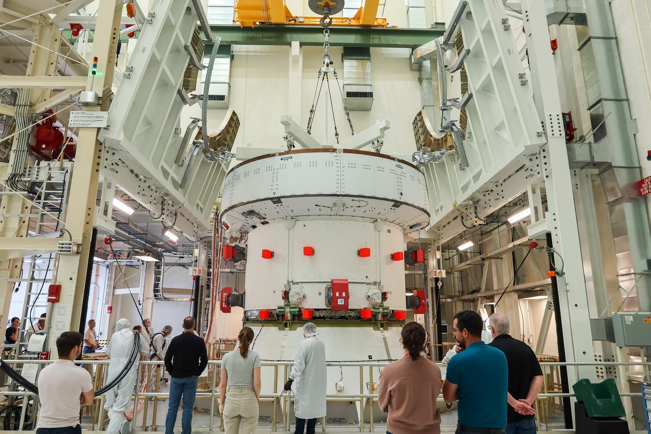
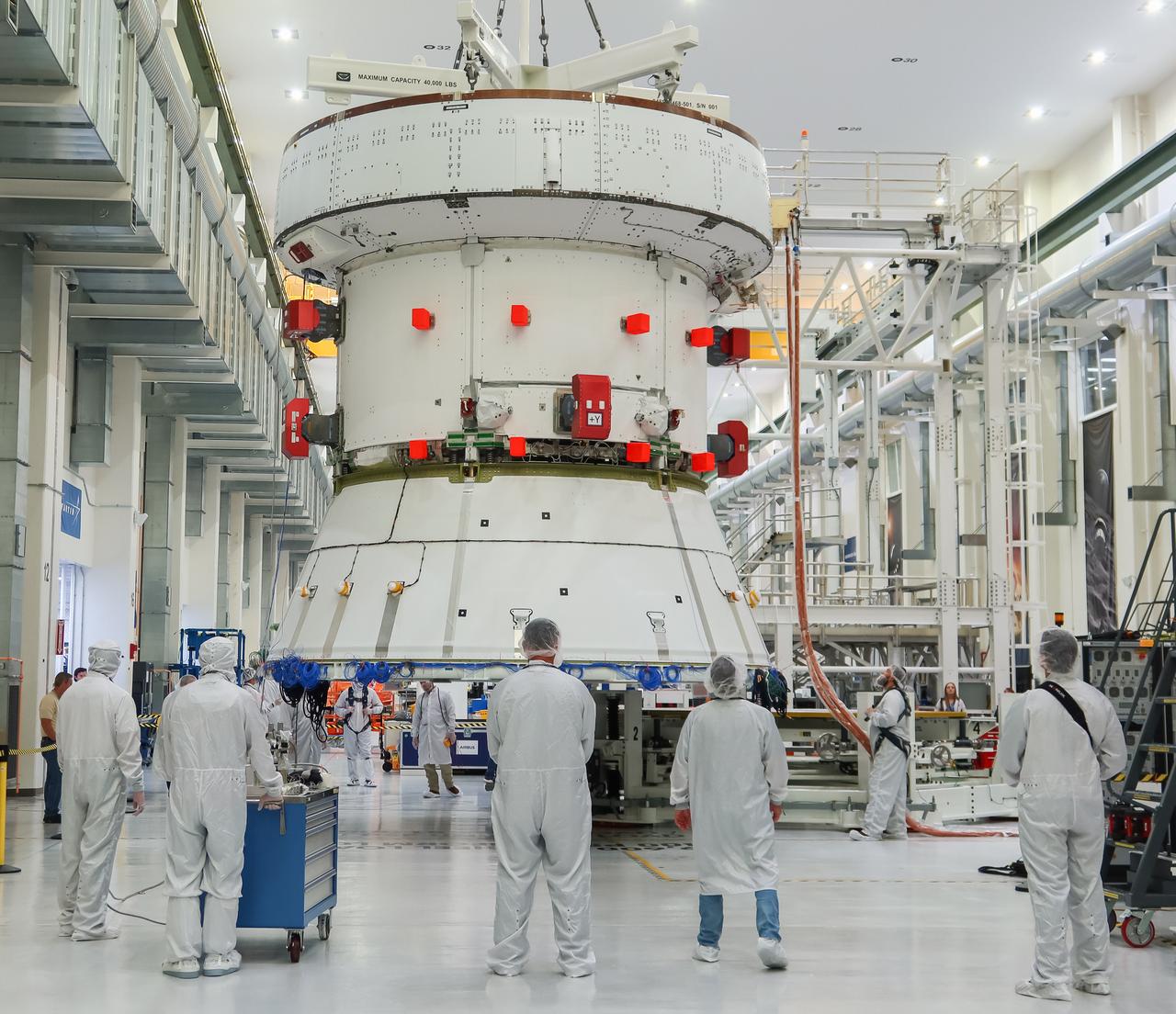
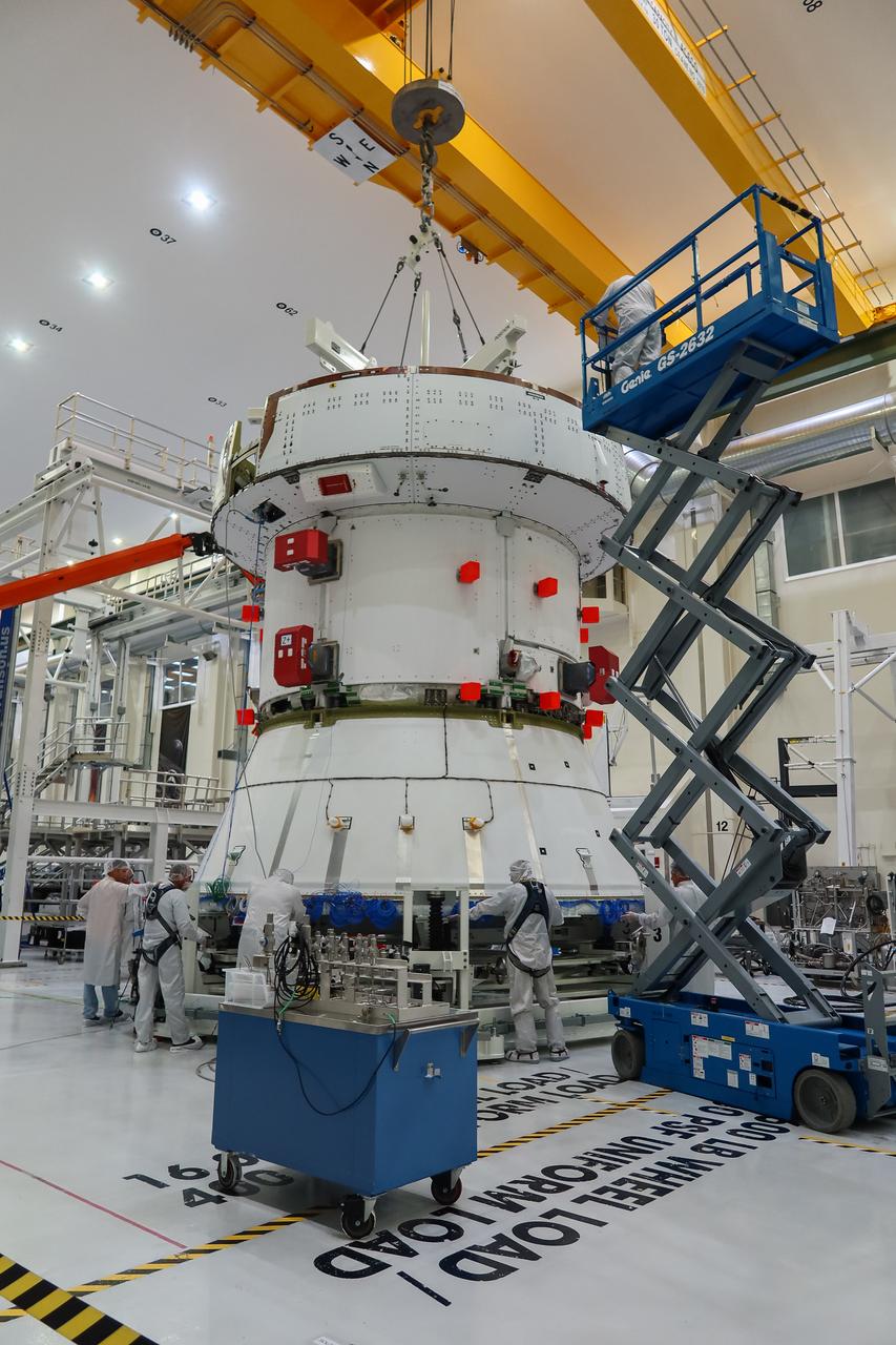
The European Service Module (ESM) for NASA’s Artemis II mission arrives at the Final Assembly and System Testing (FAST) cell inside the high bay of the Neil A. Armstrong Operations and Checkout Building at NASA’s Kennedy Space Center in Florida on May 22, 2023. Teams from NASA and Lockheed Martin are transferring the service module to the FAST (final assembly and system testing) cell for final checkouts before it is stacked with the Orion crew module.. The powerhouse that will fuel and propel Orion in space, the ESM will be used for Artemis II, the first Artemis mission flying crew aboard Orion.
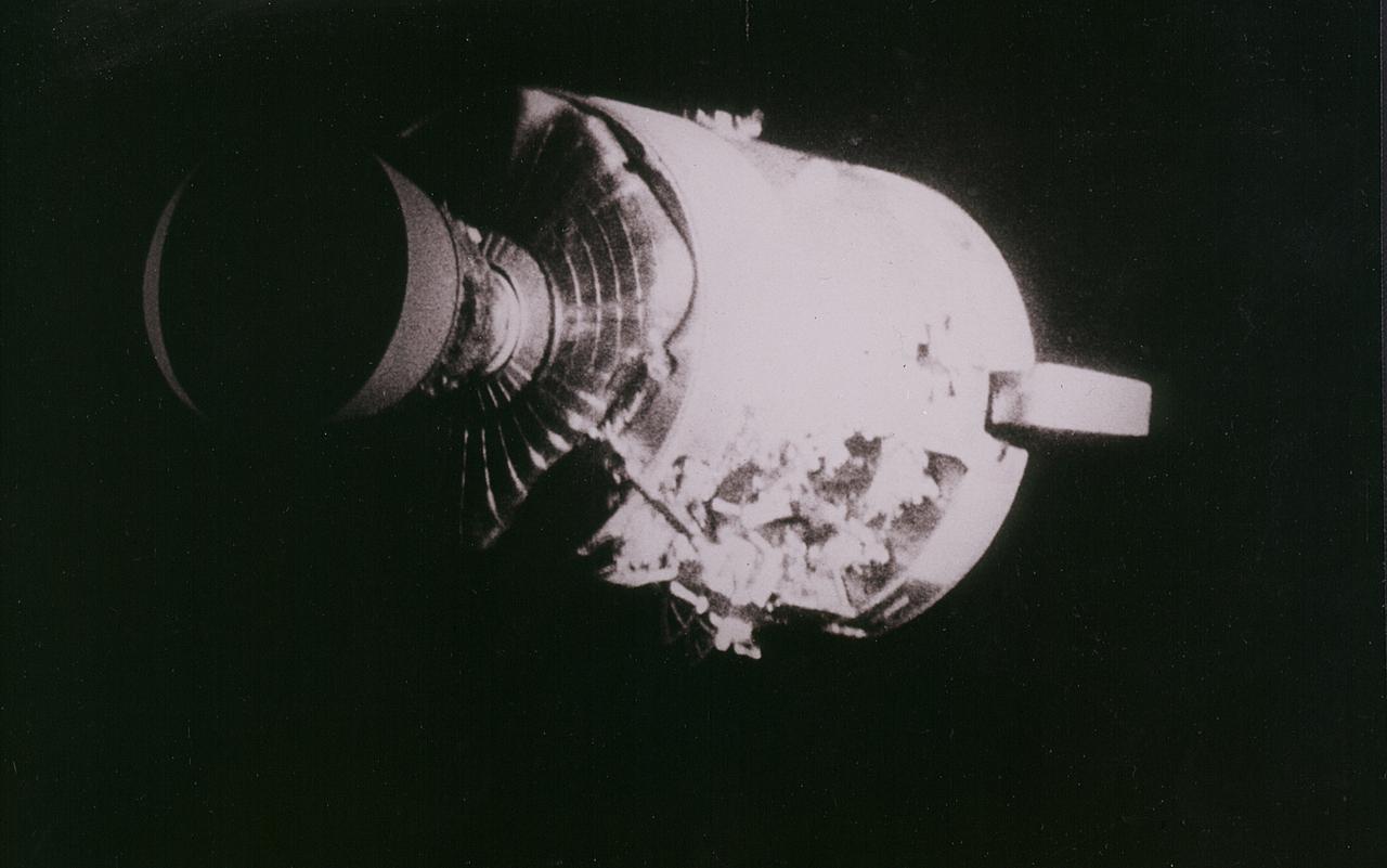
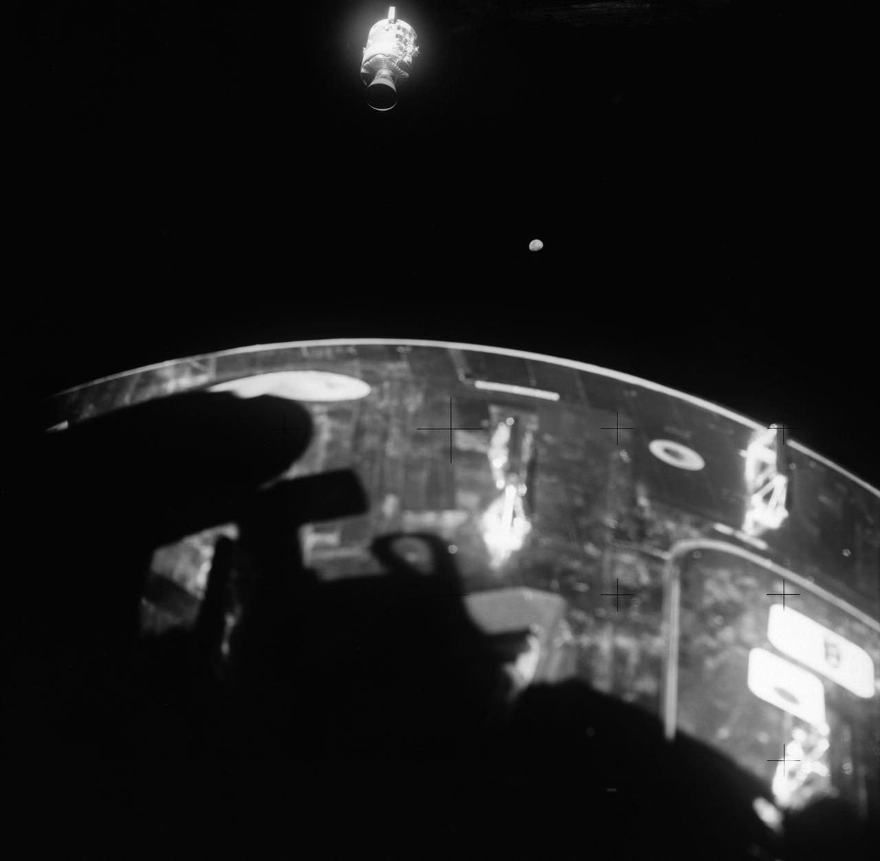
Apollo 13 onboard photo: This view of the severely damaged Apollo 13 Service Module was photographed from the Lunar Module/Command Module following the jettison of the Service Module. As seen here, an entire panel of the Service Module was blown away by the apparent explosion of oxygen tank number two located in Sector 4 of the Service Module. Two of the three fuel cells are visible just forward (above) the heavily damaged area. Three fuel cells, two oxygen tanks, and two hydrogen tanks, are located in Sector 4. The damaged area is located above the S-band high gain anterna. Nearest the camera is the Service Propulsion System (SPS) engine and nozzle. The damage to the Service Module caused the Apollo 13 crewmen to use the Lunar Module as a lifeboat. The Lunar Module was jettisoned by the Command Module just prior to Earth re-entry.
This view of the damaged Apollo 13 Service Module (SM) was photographed from the Lunar Module/Command Module following SM jettisoning. As seen here, an entire panel on the SM was blown away by the apparent explosion of oxygen tank number two located in Sector 4 of the SM. Two of the three fuel cells are visible just forward (above) the heavily damaged area. Three fuel cells, two oxygen tanks, and two hydrogen tanks are locate in Sector 4. The damaged area is located above the S-band high gain antenna. Nearest the camera is the Service Propulsion System (SPS) engine and nozzle. The damage to the SM caused the Apollo 13 crewmen to use the Lunar Module (LM) as a "lifeboat". The LM was jettisoned just prior to Earth reentry by the Command Module.
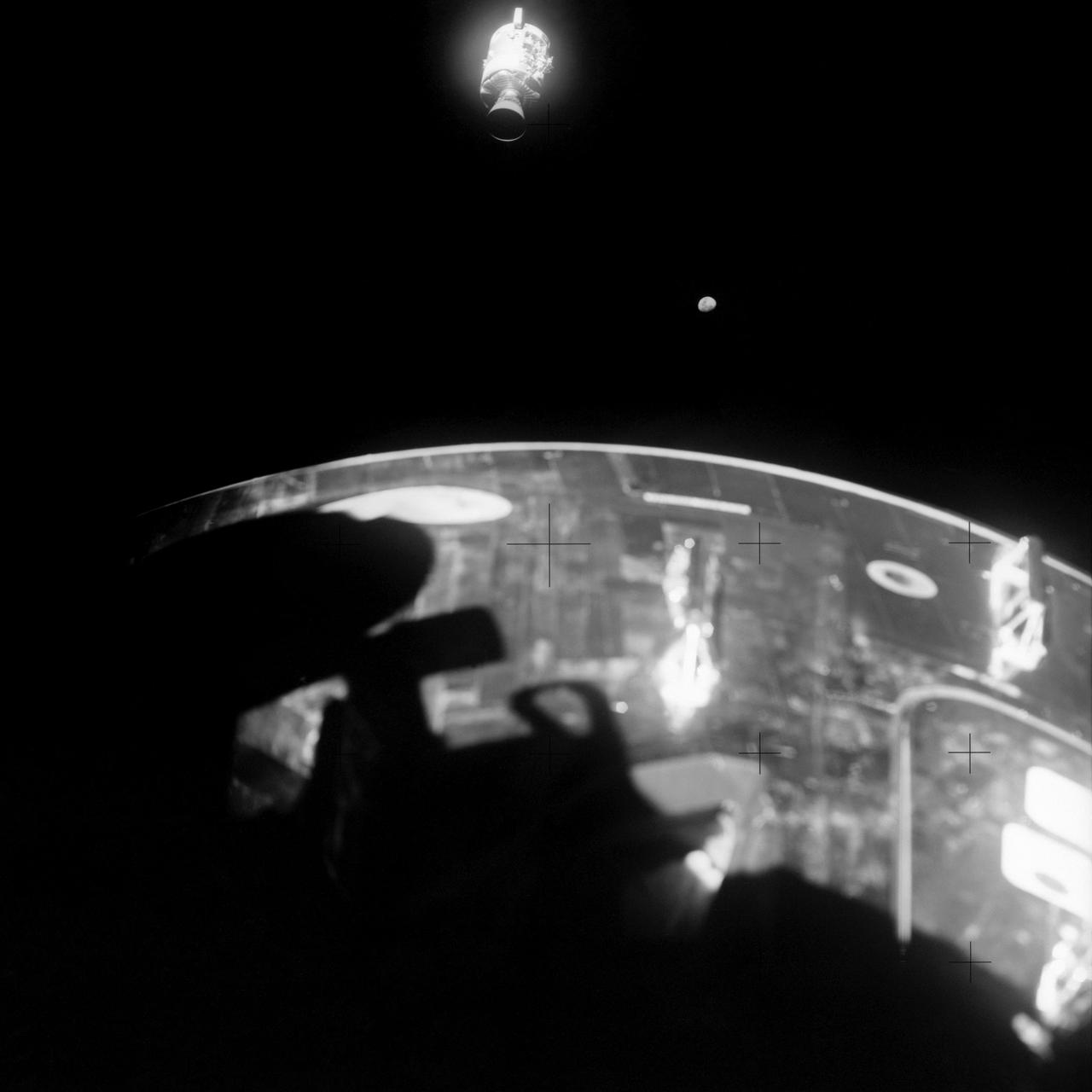
AS13-59-8501 (17 April 1970) --- This view of the severely damaged Apollo 13 Service Module (SM) was photographed from the Lunar Module/Command Module (LM/CM) following SM jettisoning. As seen here, an entire panel on the SM was blown away by the apparent explosion of oxygen tank number two located in Sector 4 of the SM. Two of the three fuel cells are visible just forward (above) the heavily damaged area. Three fuel cells, two oxygen tanks, and two hydrogen tanks are located in Sector 4. The damaged area is located above the S-Band high gain antenna. Nearest the camera is the Service Propulsion System (SPS) engine and nozzle. The damage to the SM caused the Apollo 13 crew men to use the LM as a "lifeboat." The LM was jettisoned just prior to Earth re-entry by the CM.
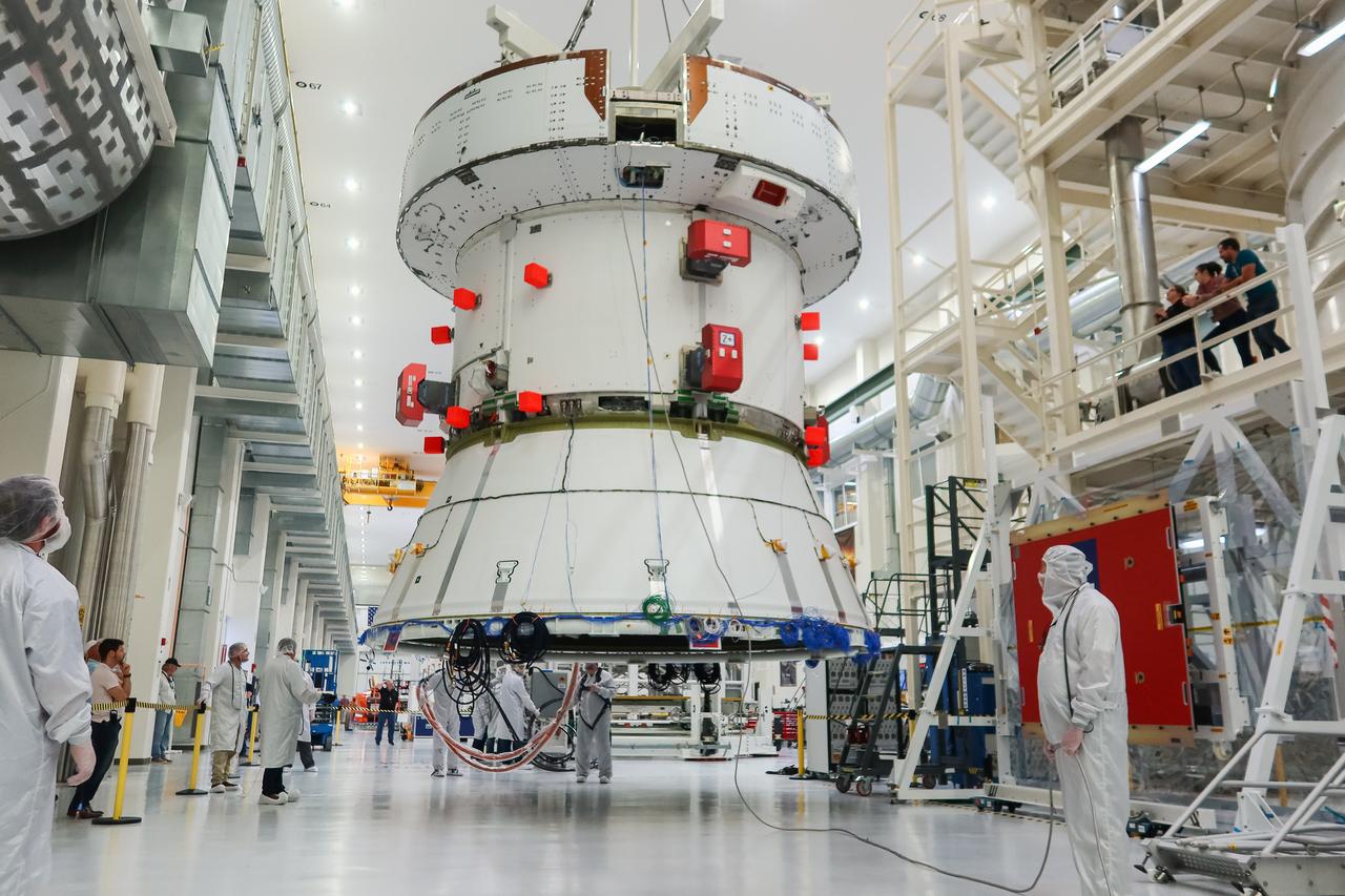
A crane slowly moves the European Service Module (ESM) for NASA’s Artemis II mission into the FAST (final assembly and system testing) cell inside the high bay of the Neil A. Armstrong Operations and Checkout Building at NASA’s Kennedy Space Center in Florida on May 22, 2023. Teams from NASA and Lockheed Martin are transferring the service module to the FAST cell for final checkouts before it is stacked with the Orion crew module.. The powerhouse that will fuel and propel Orion in space, the ESM will be used for Artemis II, the first Artemis mission flying crew aboard Orion.
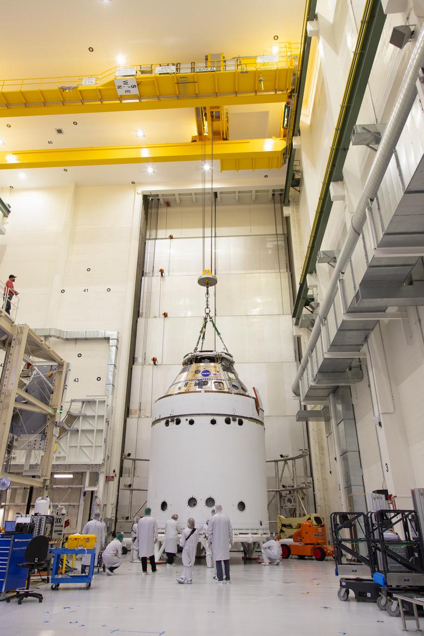
A crane lowers the European Service Module (ESM) for NASA’s Artemis II mission into the FAST (final assembly and system testing) cell inside the high bay of the Neil A. Armstrong Operations and Checkout Building at NASA’s Kennedy Space Center in Florida on May 22, 2023. Teams from NASA and Lockheed Martin are transferring the service module to the FAST cell for final checkouts before it is stacked with the Orion crew module. The powerhouse that will fuel and propel Orion in space, the ESM will be used for Artemis II, the first Artemis mission flying crew aboard Orion.
A crane returns NASA’s Artemis II Orion spacecraft to the Final Assembly and System Testing (FAST) cell inside the Neil A. Armstrong Operations and Checkout Building at NASA’s Kennedy Space Center in Florida on Friday, March 21, 2025, following installation of four solar array winds and adapter jettison fairings. Once complete, the Orion spacecraft will be transported to other facilities for fueling and integration with its launch abort system before arriving at the Vehicle Assembly Building where it will be stacked atop the SLS (Space Launch System) by NASA’s Exploration Ground System team at the Vehicle Assembly Building in preparations for Artemis II launch operations.
A crane returns NASA’s Artemis II Orion spacecraft to the Final Assembly and System Testing (FAST) cell inside the Neil A. Armstrong Operations and Checkout Building at NASA’s Kennedy Space Center in Florida on Friday, March 21, 2025, following installation of four solar array winds and adapter jettison fairings. Once complete, the Orion spacecraft will be transported to other facilities for fueling and integration with its launch abort system before arriving at the Vehicle Assembly Building where it will be stacked atop the SLS (Space Launch System) by NASA’s Exploration Ground System team at the Vehicle Assembly Building in preparations for Artemis II launch operations.
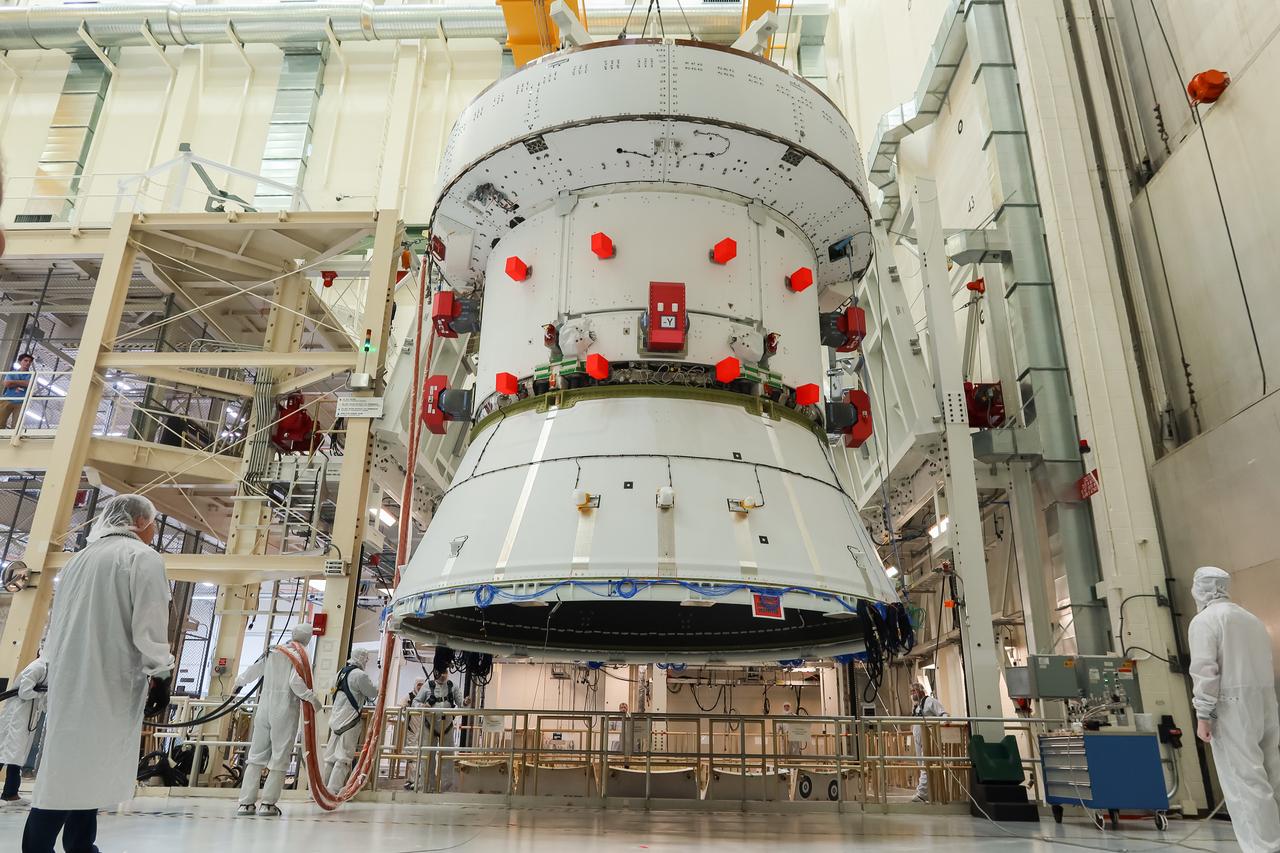
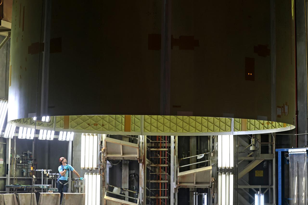
The European Service Module (ESM) for NASA’s Artemis II mission is lifted by crane inside the high bay of the Neil A. Armstrong Operations and Checkout Building at NASA’s Kennedy Space Center in Florida on May 22, 2023. Teams from NASA and Lockheed Martin are preparing the service module for transfer to the FAST (final assembly and system testing) cell for final checkouts before it is stacked with the Orion crew module. The powerhouse that will fuel and propel Orion in space, the ESM will be used for Artemis II, the first Artemis mission flying crew aboard Orion.
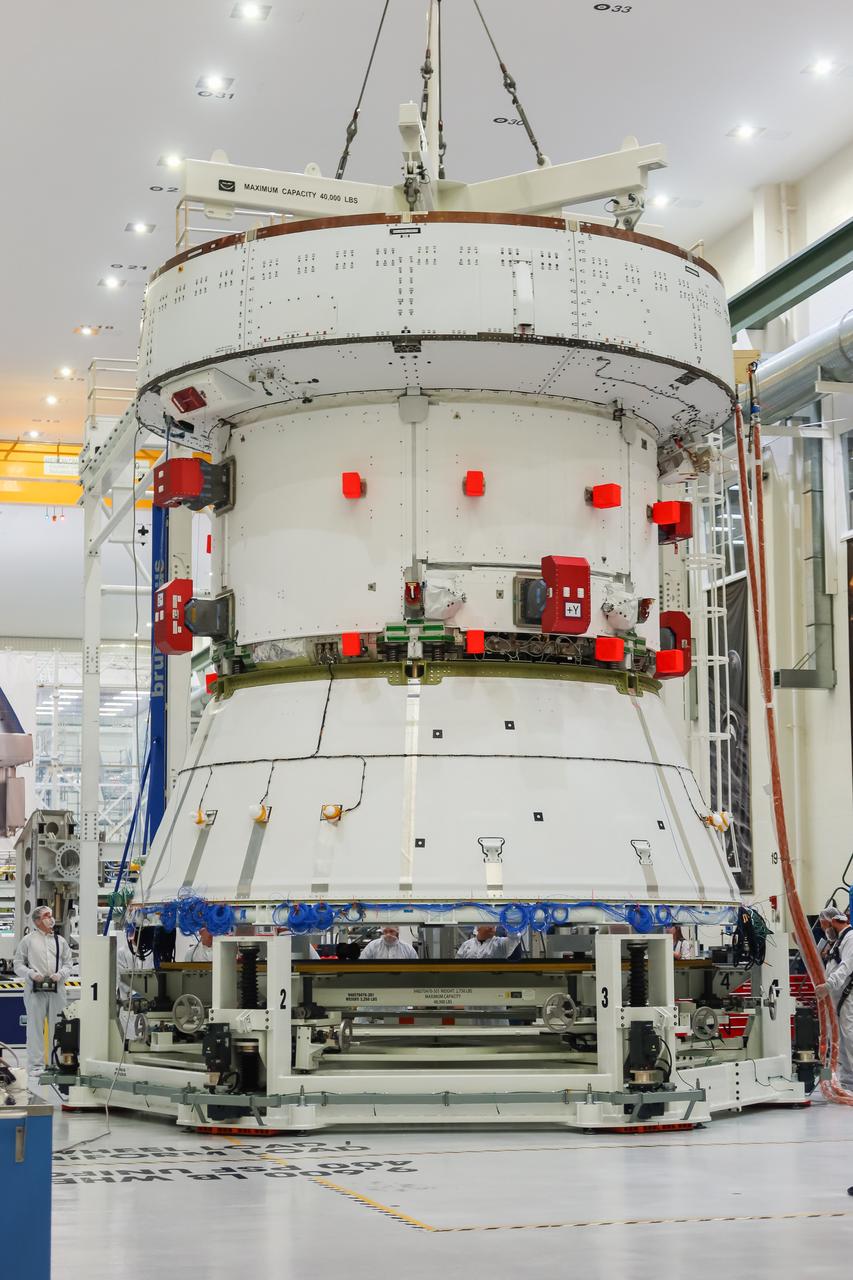
The European Service Module (ESM) for NASA’s Artemis II mission is lifted by crane inside the high bay of the Neil A. Armstrong Operations and Checkout Building at NASA’s Kennedy Space Center in Florida on May 22, 2023. Teams from NASA and Lockheed Martin are preparing the service module for transfer to the FAST (final assembly and system testing) cell for final checkouts before it is stacked with the Orion crew module. The powerhouse that will fuel and propel Orion in space, the ESM will be used for Artemis II, the first Artemis mission flying crew aboard Orion.
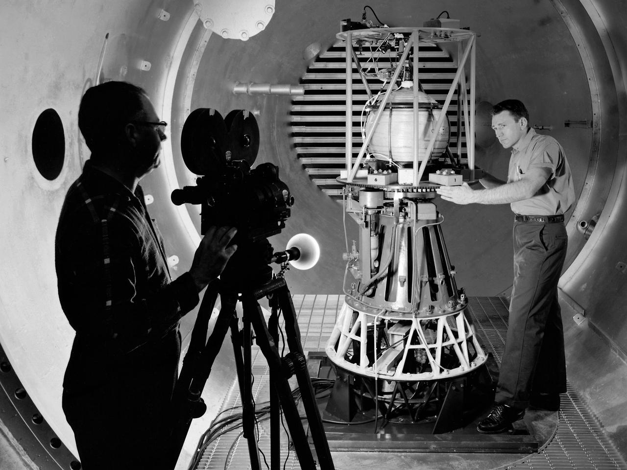
Mechanic Howard Wine inspects the setup of a spin isolator in Cell 2 of the Propulsion Systems Laboratory at the National Aeronautics and Space Administration (NASA) Lewis Research Center. Photographer Al Jecko filmed the proceedings. This test was unique in that the chamber’s altitude system was used, but not its inlet air flow. The test was in preparation for an upcoming launch of modified liquid hydrogen propellant tank on a sounding rocket. This Weightlessness Analysis Sounding Probe (WASP) was part of Lewis investigation into methods for controlling partially filled liquid hydrogen fuel tanks during flight. Second-stage rockets, the Centaur in particular, were designed to stop their engines and coast, then restart them when needed. During this coast period, the propellant often shifted inside the tank. This movement could throw the rocket off course or result in the sloshing of fuel away from the fuel pump. Wine was one of only three journeymen mechanics at Lewis when he was hired in January 1954. He spent his first decade in the Propulsion Systems Laboratory and was soon named a section head. Wine went on to serve as Assistant Division Chief and later served as an assistant to the director. Jecko joined the center in 1947 as a photographer and artist. He studied at the Cleveland School or Art and was known for his cartoon drawing. He worked at the center for 26 years.
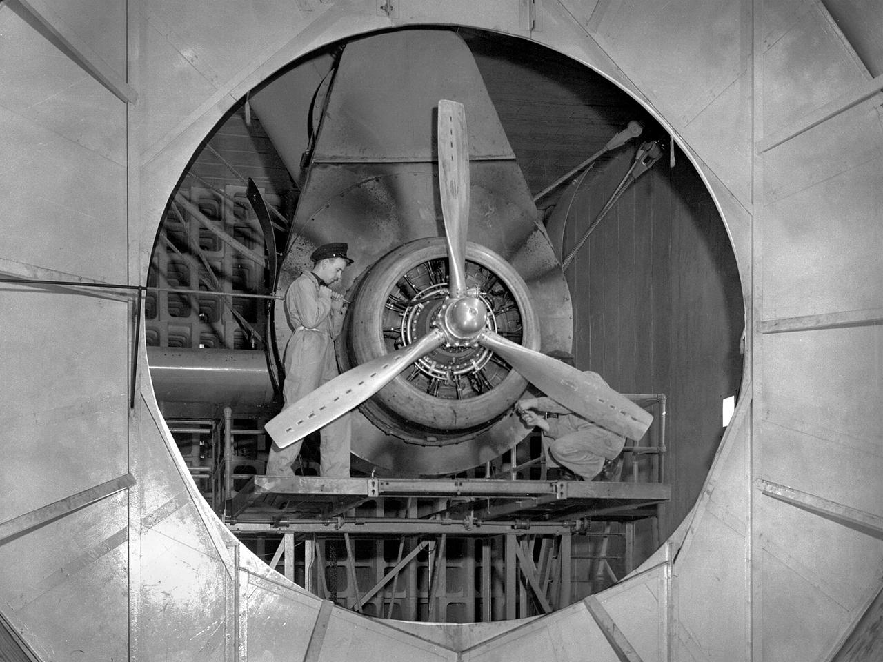
A Wright Aeronautical R–2600 Cyclone piston engine installed in the Engine Propeller Research Building, or Prop House, at the National Advisory Committee for Aeronautics (NACA) Aircraft Engine Research Laboratory. The R–2600 was among the most powerful engines that emerged during World War II. The engine, which was developed for commercial applications in 1939, was used to power the North American B–25 bomber and several other midsize military aircraft. The higher altitudes required by the military caused problems with the engine's cooling and fuel systems. The military requested that the Aircraft Engine Research Laboratory analyze the performance of the R–2600, improve its cooling system, and reduce engine knock. The NACA researchers subjected the engine to numerous tests in its Prop House. The R–2600 was the subject of the laboratory's first technical report, which was written by members of the Fuels and Lubricants Division. The Prop House contained soundproof test cells in which piston engines and propellers were mounted and operated at high powers. Electrically driven fans drew air through ducts to create a stream of cooling air over the engines. Researchers tested the performance of fuels, turbochargers, water-injection and cooling systems here during World War II. The facility was also investigated a captured German V–I buzz bomb during the war.
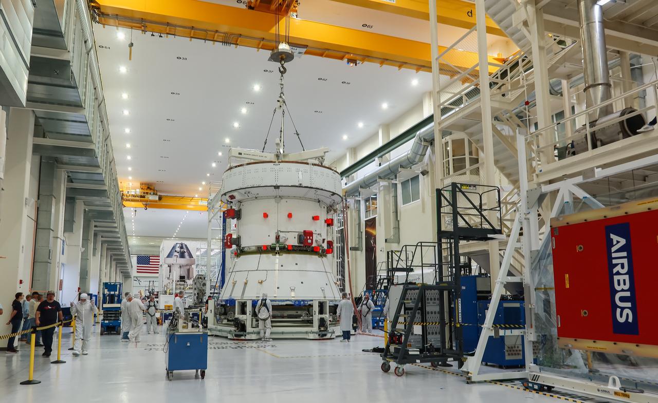
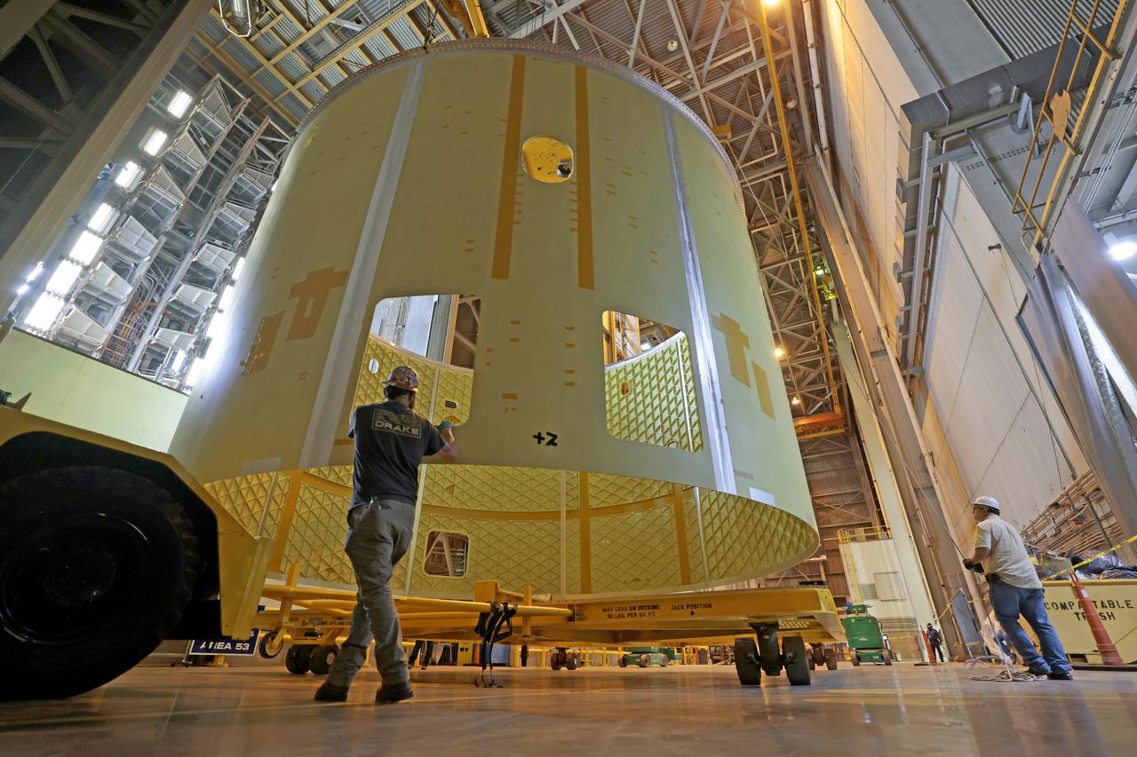
The European Service Module (ESM) for NASA’s Artemis II mission is lifted by crane and moved along the center aisle of the high bay inside the Neil A. Armstrong Operations and Checkout Building at NASA’s Kennedy Space Center in Florida on May 22, 2023. Teams from NASA and Lockheed Martin are preparing the service module for transfer to the FAST (final assembly and system testing) cell for final checkouts before it is stacked with the Orion crew module.. The powerhouse that will fuel and propel Orion in space, the ESM will be used for Artemis II, the first Artemis mission flying crew aboard Orion.
A crane moves the European Service Module (ESM) for NASA’s Artemis II mission along the center aisle of the high bay inside the Neil A. Armstrong Operations and Checkout Building at NASA’s Kennedy Space Center in Florida on May 22, 2023. Teams from NASA and Lockheed Martin are transferring the service module to the FAST (final assembly and system testing) cell for final checkouts before it is stacked with the Orion crew module.. The powerhouse that will fuel and propel Orion in space, the ESM will be used for Artemis II, the first Artemis mission flying crew aboard Orion.

Engineers and technicians monitor the progress as the European Service Module (ESM) for NASA’s Artemis II mission is lifted by crane inside the high bay of the Neil A. Armstrong Operations and Checkout Building at NASA’s Kennedy Space Center in Florida on May 22, 2023. Teams from NASA and Lockheed Martin are preparing the service module for transfer to the FAST (final assembly and system testing) cell for final checkouts before it is stacked with the Orion crew module.. The powerhouse that will fuel and propel Orion in space, the ESM will be used for Artemis II, the first Artemis mission flying crew aboard Orion.
Preparations are underway to lift the European Service Module (ESM) for NASA’s Artemis II mission by crane inside the high bay of the Neil A. Armstrong Operations and Checkout Building at NASA’s Kennedy Space Center in Florida on May 22, 2023. Teams from NASA and Lockheed Martin are preparing the service module for transfer to the FAST (final assembly and system testing) cell for final checkouts before it is stacked with Orion crew module. The powerhouse that will fuel and propel Orion in space, the ESM will be used for Artemis II, the first Artemis mission flying crew aboard Orion.
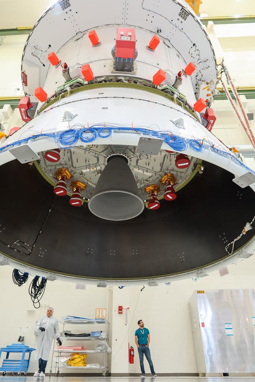
A view looking up from beneath the European Service Module (ESM) for NASA’s Artemis II mission as it is moved by crane along the center aisle of the high bay inside the Neil A. Armstrong Operations and Checkout Building at NASA’s Kennedy Space Center in Florida on May 22, 2023. Teams from NASA and Lockheed Martin are transferring the service module to the FAST (final assembly and system testing) cell for final checkouts before it is stacked with the Orion crew module.. The powerhouse that will fuel and propel Orion in space, the ESM will be used for Artemis II, the first Artemis mission flying crew aboard Orion.
Engineers and technicians monitor the progress as the European Service Module (ESM) for NASA’s Artemis II mission is lifted by crane inside the high bay of the Neil A. Armstrong Operations and Checkout Building at NASA’s Kennedy Space Center in Florida on May 22, 2023. Teams from NASA and Lockheed Martin are preparing the service module for transfer to the FAST (final assembly and system testing) cell for final checkouts before it is stacked with the Orion crew module.. The powerhouse that will fuel and propel Orion in space, the ESM will be used for Artemis II, the first Artemis mission flying crew aboard Orion.
The European Service Module (ESM) for NASA’s Artemis II mission is lifted by crane and moved along the center aisle of the high bay inside the Neil A. Armstrong Operations and Checkout Building at NASA’s Kennedy Space Center in Florida on May 22, 2023. Teams from NASA and Lockheed Martin are preparing the service module for transfer to the FAST (final assembly and system testing) cell for final checkouts before it is stacked with the Orion crew module.. The powerhouse that will fuel and propel Orion in space, the ESM will be used for Artemis II, the first Artemis mission flying crew aboard Orion.
A crane moves the European Service Module (ESM) for NASA’s Artemis II mission along the center aisle of the high bay inside the Neil A. Armstrong Operations and Checkout Building at NASA’s Kennedy Space Center in Florida on May 22, 2023. Teams from NASA and Lockheed Martin are preparing the service module for transfer to the FAST (final assembly and system testing) cell for final checkouts before it is stacked with the Orion crew module.. The powerhouse that will fuel and propel Orion in space, the ESM will be used for Artemis II, the first Artemis mission flying crew aboard Orion.
Preparations are underway to lift the European Service Module (ESM) for NASA’s Artemis II mission by crane inside the high bay of the Neil A. Armstrong Operations and Checkout Building at NASA’s Kennedy Space Center in Florida on May 22, 2023. Teams from NASA and Lockheed Martin are preparing the service module for transfer to the FAST (final assembly and system testing) cell for final checkouts before it is stacked with the Orion crew module. The powerhouse that will fuel and propel Orion in space, the ESM will be used for Artemis II, the first Artemis mission flying crew aboard Orion.
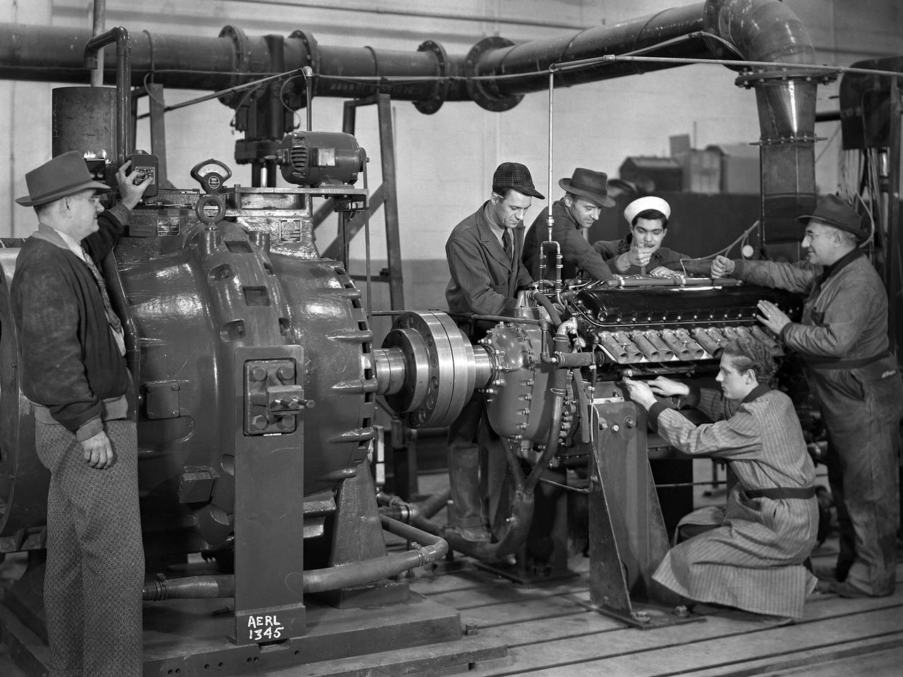
The first research assignment specifically created for the National Advisory Committee for Aeronautics’ (NACA) new Aircraft Engine Research Laboratory was the integration of a supercharger into the Allison V–1710 engine. The military was relying on the liquid-cooled V–1710 to power several types of World War II fighter aircraft and wanted to improve the engine's speed and altitude performance. Superchargers forced additional airflow into the combustion chamber, which increased the engine’s performance resulting in greater altitudes and speeds. They also generated excess heat that affected the engine cylinders, oil, and fuel. In 1943 the military tasked the new Aircraft Engine Research Laboratory to integrate the supercharger, improve the cooling system, and remedy associated engine knock. Three Allison engines were provided to the laboratory’s research divisions. One group was tasked with improving the supercharger performance, another analyzed the effect of the increased heat on knock in the fuel, one was responsible for improving the cooling system, and another would install the new components on the engine with minimal drag penalties. The modified engines were installed on this 2000-horsepower dynamotor stand in a test cell within the Engine Research Building. The researchers could run the engine at different temperatures, fuel-air ratios, and speeds. When the modifications were complete, the improved V–1710 was flight tested on a P–63A Kingcobra loaned to the NACA for this project.
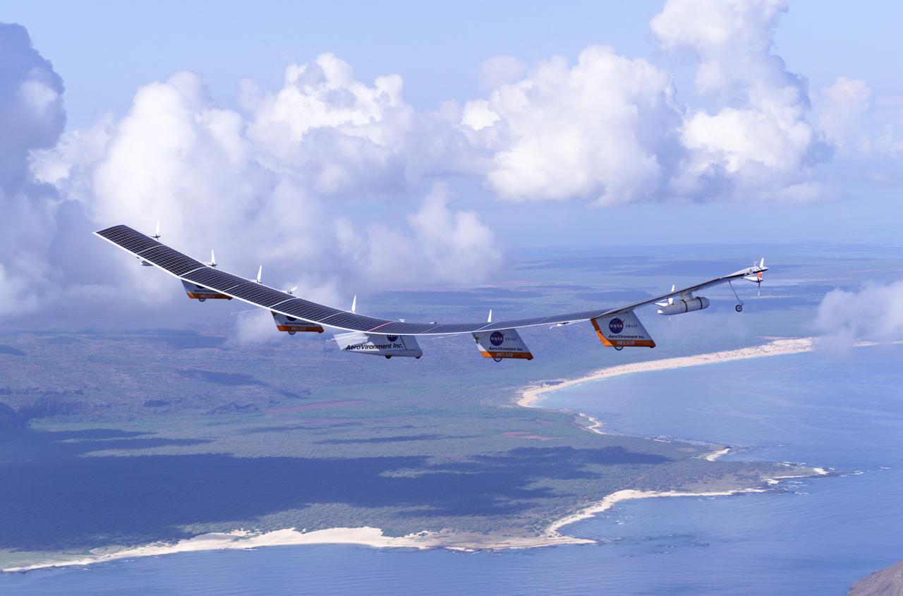
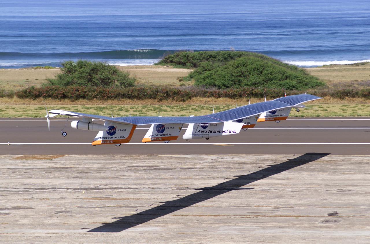
The first flight of a large aircraft to be powered by electric fuel cells began with a takeoff at 8:43 a.m. HST today from the Hawaiian island of Kauai. The Helios Prototype flying wing, built by AeroVironment, Inc., of Monrovia, Calif., as part of NASA's Environmental Research Aircraft and Sensor Technology (ERAST) program, used solar panels to power its 10 electric motors for takeoff and during daylight portions of its planned 20-hour shakedown flight. As sunlight diminishes, Helios will switch to a fuel cell system to continue flight into the night. The takeoff set the stage for a two-day Helios endurance flight in the stratosphere planned for mid-July. The Helios wing, spanning 247 feet and weighing about 2,400 pounds, is giving NASA and industry engineers confidence that remotely piloted aircraft will be able to stay aloft for weeks at a time, providing environmental monitoring capabilities and telecommunications relay services. Helios is an all-electric airplane. In addition to being non-polluting, Helios can fly above storms, and use the power of the sun to stay aloft during daylight. Key to the success of this type of aircraft is the ability to fly in darkness, using fuel cells when sunlight cannot furnish energy. Helios flew over the Navy's Pacific Missile Range Facility where favorable sun exposure and test ranges closed to other air traffic benefited the NASA research effort. In 2003 the aircraft was lost to a crash.

The first flight of a large aircraft to be powered by electric fuel cells began with a takeoff at 8:43 a.m. HST today from the Hawaiian island of Kauai. The Helios Prototype flying wing, built by AeroVironment, Inc., of Monrovia, Calif., as part of NASA's Environmental Research Aircraft and Sensor Technology (ERAST) program, used solar panels to power its 10 electric motors for takeoff and during daylight portions of its planned 20-hour shakedown flight. As sunlight diminishes, Helios will switch to a fuel cell system to continue flight into the night. The takeoff set the stage for a two-day Helios endurance flight in the stratosphere planned for mid-July. The Helios wing, spanning 247 feet and weighing about 2,400 pounds, is giving NASA and industry engineers confidence that remotely piloted aircraft will be able to stay aloft for weeks at a time, providing environmental monitoring capabilities and telecommunications relay services. Helios is an all-electric airplane. In addition to being non-polluting, Helios can fly above storms, and use the power of the sun to stay aloft during daylight. Key to the success of this type of aircraft is the ability to fly in darkness, using fuel cells when sunlight cannot furnish energy. Helios flew over the Navy's Pacific Missile Range Facility where favorable sun exposure and test ranges closed to other air traffic benefited the NASA research effort. In 2003 the aircraft was lost to a crash.
The first flight of a large aircraft to be powered by electric fuel cells began with a takeoff at 8:43 a.m. HST today from the Hawaiian island of Kauai. The Helios Prototype flying wing, built by AeroVironment, Inc., of Monrovia, Calif., as part of NASA's Environmental Research Aircraft and Sensor Technology (ERAST) program, used solar panels to power its 10 electric motors for takeoff and during daylight portions of its planned 20-hour shakedown flight. As sunlight diminishes, Helios will switch to a fuel cell system to continue flight into the night. The takeoff set the stage for a two-day Helios endurance flight in the stratosphere planned for mid-July. The Helios wing, spanning 247 feet and weighing about 2,400 pounds, gave NASA and industry engineers confidence that remotely piloted aircraft would be able to stay aloft for weeks at a time, providing environmental monitoring capabilities and telecommunications relay services. Helios was an all-electric airplane. In addition to being non-polluting, Helios flew above storms, and used the power of the sun to stay aloft during daylight. Key to the success of this type of aircraft was the ability to fly in darkness, using fuel cells when sunlight cannot furnish energy. Helios flew over the Navy's Pacific Missile Range Facility where favorable sun exposure and test ranges closed to other air traffic benefited the NASA research effort. In 2003 the aircraft was lost to a crash.
The first flight of a large aircraft to be powered by electric fuel cells began with a takeoff at 8:43 a.m. HST today from the Hawaiian island of Kauai. The Helios Prototype flying wing, built by AeroVironment, Inc., of Monrovia, Calif., as part of NASA's Environmental Research Aircraft and Sensor Technology (ERAST) program, used solar panels to power its 10 electric motors for takeoff and during daylight portions of its planned 20-hour shakedown flight. As sunlight diminishes, Helios will switch to a fuel cell system to continue flight into the night. The takeoff set the stage for a two-day Helios endurance flight in the stratosphere planned for mid-July. The Helios wing, spanning 247 feet and weighing about 2,400 pounds, is giving NASA and industry engineers confidence that remotely piloted aircraft will be able to stay aloft for weeks at a time, providing environmental monitoring capabilities and telecommunications relay services. Helios is an all-electric airplane. In addition to being non-polluting, Helios can fly above storms, and use the power of the sun to stay aloft during daylight. Key to the success of this type of aircraft is the ability to fly in darkness, using fuel cells when sunlight cannot furnish energy. Helios flew over the Navy's Pacific Missile Range Facility where favorable sun exposure and test ranges closed to other air traffic benefited the NASA research effort. In 2003 the aircraft was lost to a crash.

The first flight of a large aircraft to be powered by electric fuel cells began with a takeoff at 8:43 a.m. HST today from the Hawaiian island of Kauai. The Helios Prototype flying wing, built by AeroVironment, Inc., of Monrovia, Calif., as part of NASA's Environmental Research Aircraft and Sensor Technology (ERAST) program, used solar panels to power its 10 electric motors for takeoff and during daylight portions of its planned 20-hour shakedown flight. As sunlight diminishes, Helios will switch to a fuel cell system to continue flight into the night. The takeoff set the stage for a two-day Helios endurance flight in the stratosphere planned for mid-July. The Helios wing, spanning 247 feet and weighing about 2,400 pounds, is giving NASA and industry engineers confidence that remotely piloted aircraft will be able to stay aloft for weeks at a time, providing environmental monitoring capabilities and telecommunications relay services. Helios is an all-electric airplane. In addition to being non-polluting, Helios can fly above storms, and use the power of the sun to stay aloft during daylight. Key to the success of this type of aircraft is the ability to fly in darkness, using fuel cells when sunlight cannot furnish energy. Helios flew over the Navy's Pacific Missile Range Facility where favorable sun exposure and test ranges closed to other air traffic benefited the NASA research effort. In 2003 the aircraft was lost to a crash.
Technicians at NASA’s Michoud Assembly Facility move the engine section of NASA’s Space Launch System rocket for Artemis IV from the Vertical Assembly Building to Cell G for weld priming. This hardware is the first large piece manufactured for the Artemis IV mission and makes up the lowest portion of the 212-foot-tall core stage. When complete, the engine section will house the four RS-25 engines and include vital systems for mounting, controlling and delivering fuel from the propellant tanks to the rocket’s engines. Together with its four RS-25 engines and its twin solid rocket boosters, it will produce 8.8 million pounds of thrust to send NASA’s Orion spacecraft, astronauts, and supplies beyond Earth’s orbit to the Moon and, ultimately, Mars. Offering more payload mass, volume capability, and energy to speed missions through space, the SLS rocket, along with NASA’s Gateway in lunar orbit, the Human Landing System, and Orion spacecraft, is part of NASA’s backbone for deep space exploration and the Artemis lunar program. No other rocket is capable of carrying astronauts in Orion around the Moon in a single mission. Image credit: NASA/Michael DeMocker
Technicians at NASA’s Michoud Assembly Facility move the engine section of NASA’s Space Launch System rocket for Artemis IV from the Vertical Assembly Building to Cell G for weld priming. This hardware is the first large piece manufactured for the Artemis IV mission and makes up the lowest portion of the 212-foot-tall core stage. When complete, the engine section will house the four RS-25 engines and include vital systems for mounting, controlling and delivering fuel from the propellant tanks to the rocket’s engines. Together with its four RS-25 engines and its twin solid rocket boosters, it will produce 8.8 million pounds of thrust to send NASA’s Orion spacecraft, astronauts, and supplies beyond Earth’s orbit to the Moon and, ultimately, Mars. Offering more payload mass, volume capability, and energy to speed missions through space, the SLS rocket, along with NASA’s Gateway in lunar orbit, the Human Landing System, and Orion spacecraft, is part of NASA’s backbone for deep space exploration and the Artemis lunar program. No other rocket is capable of carrying astronauts in Orion around the Moon in a single mission. Image credit: NASA/Michael DeMocker

Technicians at NASA’s Michoud Assembly Facility move the engine section of NASA’s Space Launch System rocket for Artemis IV from the Vertical Assembly Building to Cell G for weld priming. This hardware is the first large piece manufactured for the Artemis IV mission and makes up the lowest portion of the 212-foot-tall core stage. When complete, the engine section will house the four RS-25 engines and include vital systems for mounting, controlling and delivering fuel from the propellant tanks to the rocket’s engines. Together with its four RS-25 engines and its twin solid rocket boosters, it will produce 8.8 million pounds of thrust to send NASA’s Orion spacecraft, astronauts, and supplies beyond Earth’s orbit to the Moon and, ultimately, Mars. Offering more payload mass, volume capability, and energy to speed missions through space, the SLS rocket, along with NASA’s Gateway in lunar orbit, the Human Landing System, and Orion spacecraft, is part of NASA’s backbone for deep space exploration and the Artemis lunar program. No other rocket is capable of carrying astronauts in Orion around the Moon in a single mission. Image credit: NASA/Michael DeMocker
Technicians at NASA’s Michoud Assembly Facility move the engine section of NASA’s Space Launch System rocket for Artemis IV from the Vertical Assembly Building to Cell G for weld priming. This hardware is the first large piece manufactured for the Artemis IV mission and makes up the lowest portion of the 212-foot-tall core stage. When complete, the engine section will house the four RS-25 engines and include vital systems for mounting, controlling and delivering fuel from the propellant tanks to the rocket’s engines. Together with its four RS-25 engines and its twin solid rocket boosters, it will produce 8.8 million pounds of thrust to send NASA’s Orion spacecraft, astronauts, and supplies beyond Earth’s orbit to the Moon and, ultimately, Mars. Offering more payload mass, volume capability, and energy to speed missions through space, the SLS rocket, along with NASA’s Gateway in lunar orbit, the Human Landing System, and Orion spacecraft, is part of NASA’s backbone for deep space exploration and the Artemis lunar program. No other rocket is capable of carrying astronauts in Orion around the Moon in a single mission. Image credit: NASA/Michael DeMocker
Technicians at NASA’s Michoud Assembly Facility move the engine section of NASA’s Space Launch System rocket for Artemis IV from the Vertical Assembly Building to Cell G for weld priming. This hardware is the first large piece manufactured for the Artemis IV mission and makes up the lowest portion of the 212-foot-tall core stage. When complete, the engine section will house the four RS-25 engines and include vital systems for mounting, controlling and delivering fuel from the propellant tanks to the rocket’s engines. Together with its four RS-25 engines and its twin solid rocket boosters, it will produce 8.8 million pounds of thrust to send NASA’s Orion spacecraft, astronauts, and supplies beyond Earth’s orbit to the Moon and, ultimately, Mars. Offering more payload mass, volume capability, and energy to speed missions through space, the SLS rocket, along with NASA’s Gateway in lunar orbit, the Human Landing System, and Orion spacecraft, is part of NASA’s backbone for deep space exploration and the Artemis lunar program. No other rocket is capable of carrying astronauts in Orion around the Moon in a single mission.
Technicians at NASA’s Michoud Assembly Facility move the engine section of NASA’s Space Launch System rocket for Artemis IV out of Cell G after weld priming. This hardware is the first large piece manufactured for the Artemis IV mission and makes up the lowest portion of the 212-foot-tall core stage. When complete, the engine section will house the four RS-25 engines and include vital systems for mounting, controlling and delivering fuel from the propellant tanks to the rocket’s engines. Together with its four RS-25 engines and its twin solid rocket boosters, it will produce 8.8 million pounds of thrust to send NASA’s Orion spacecraft, astronauts, and supplies beyond Earth’s orbit to the Moon and, ultimately, Mars. Offering more payload mass, volume capability, and energy to speed missions through space, the SLS rocket, along with NASA’s Gateway in lunar orbit, the Human Landing System, and Orion spacecraft, is part of NASA’s backbone for deep space exploration and the Artemis lunar program. No other rocket is capable of carrying astronauts in Orion around the Moon in a single mission.

Technicians at NASA’s Michoud Assembly Facility move the engine section of NASA’s Space Launch System rocket for Artemis IV from the Vertical Assembly Building to Cell G for weld priming. This hardware is the first large piece manufactured for the Artemis IV mission and makes up the lowest portion of the 212-foot-tall core stage. When complete, the engine section will house the four RS-25 engines and include vital systems for mounting, controlling and delivering fuel from the propellant tanks to the rocket’s engines. Together with its four RS-25 engines and its twin solid rocket boosters, it will produce 8.8 million pounds of thrust to send NASA’s Orion spacecraft, astronauts, and supplies beyond Earth’s orbit to the Moon and, ultimately, Mars. Offering more payload mass, volume capability, and energy to speed missions through space, the SLS rocket, along with NASA’s Gateway in lunar orbit, the Human Landing System, and Orion spacecraft, is part of NASA’s backbone for deep space exploration and the Artemis lunar program. No other rocket is capable of carrying astronauts in Orion around the Moon in a single mission. Image credit: NASA/Michael DeMocker
Technicians at NASA’s Michoud Assembly Facility move the engine section of NASA’s Space Launch System rocket for Artemis IV from the Vertical Assembly Building to Cell G for weld priming. This hardware is the first large piece manufactured for the Artemis IV mission and makes up the lowest portion of the 212-foot-tall core stage. When complete, the engine section will house the four RS-25 engines and include vital systems for mounting, controlling and delivering fuel from the propellant tanks to the rocket’s engines. Together with its four RS-25 engines and its twin solid rocket boosters, it will produce 8.8 million pounds of thrust to send NASA’s Orion spacecraft, astronauts, and supplies beyond Earth’s orbit to the Moon and, ultimately, Mars. Offering more payload mass, volume capability, and energy to speed missions through space, the SLS rocket, along with NASA’s Gateway in lunar orbit, the Human Landing System, and Orion spacecraft, is part of NASA’s backbone for deep space exploration and the Artemis lunar program. No other rocket is capable of carrying astronauts in Orion around the Moon in a single mission. Image credit: NASA/Michael DeMocker
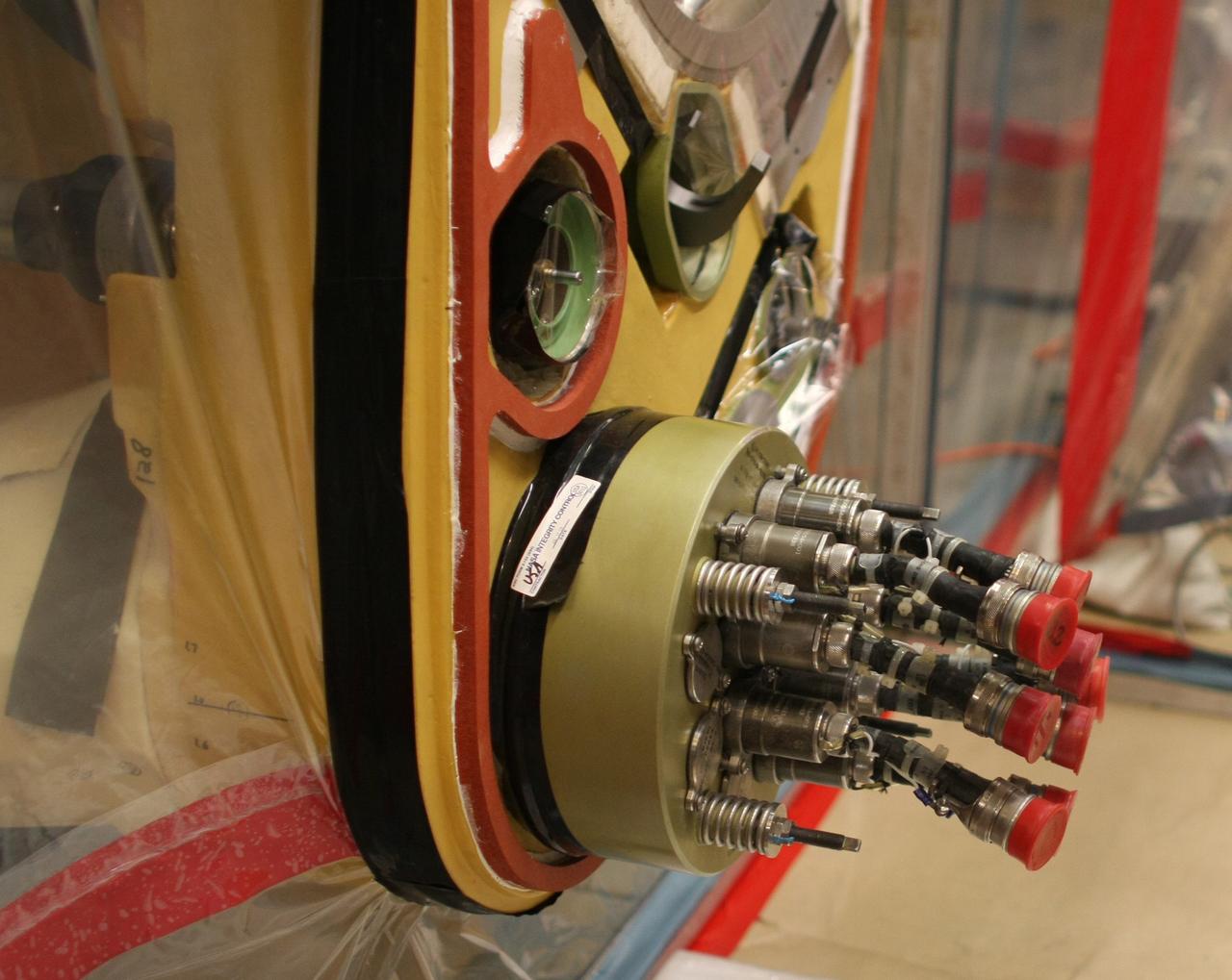
CAPE CANAVERAL, Fla. – A close up view of the quick disconnect system on Atlantis’ external tank inside a test cell in the Vehicle Assembly Building at NASA's Kennedy Space Center. Technicians prepared to replace a valve after small dings were found on the sealing surface of the quick disconnect system that handles liquid-hydrogen fuel for the shuttle’s three main engines. The tank will be attached to the twin solid rocket boosters on Aug. 3 for the STS-125 mission, the fifth and final shuttle servicing mission to NASA’s Hubble Space Telescope. During the mission, the crew will install new instruments on the telescope, including the Cosmic Origins Spectrograph and the Wide Field Camera 3. A refurbished Fine Guidance Sensor will replace one unit of three now onboard. Mission specialists will also install new gyroscopes, batteries and thermal blankets on the telescope. Launch is targeted for Oct. 8. Photo credit: NASA/Jim Grossmann
CAPE CANAVERAL, Fla. – A close up view of the quick disconnect system on Atlantis’ external tank inside a test cell in the Vehicle Assembly Building at NASA's Kennedy Space Center. Technicians prepared to replace a valve after small dings were found on the sealing surface of the quick disconnect system that handles liquid-hydrogen fuel for the shuttle’s three main engines. The tank will be attached to the twin solid rocket boosters on Aug. 3 for the STS-125 mission, the fifth and final shuttle servicing mission to NASA’s Hubble Space Telescope. During the mission, the crew will install new instruments on the telescope, including the Cosmic Origins Spectrograph and the Wide Field Camera 3. A refurbished Fine Guidance Sensor will replace one unit of three now onboard. Mission specialists will also install new gyroscopes, batteries and thermal blankets on the telescope. Launch is targeted for Oct. 8. Photo credit: NASA/Dimitri Gerondidakis
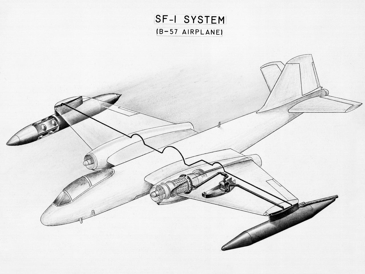
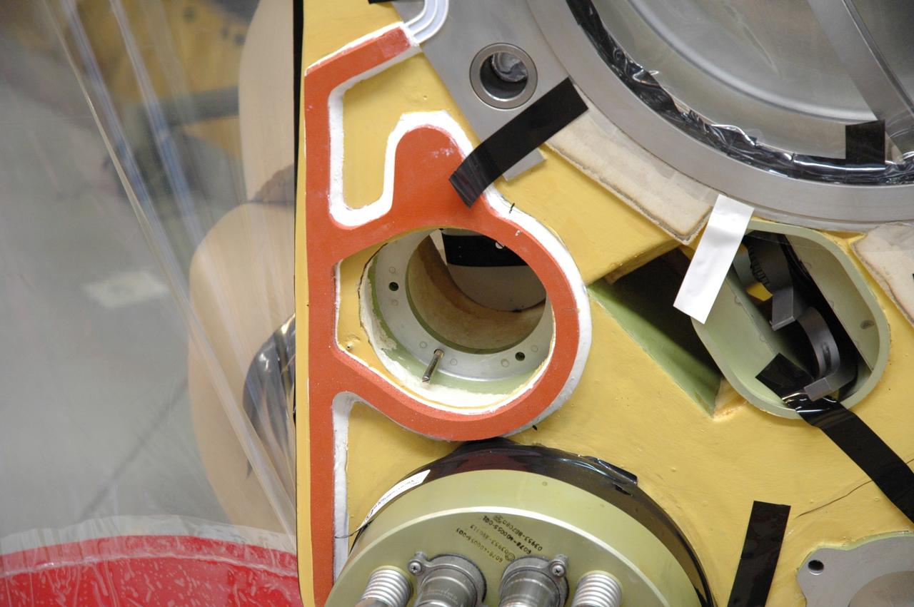
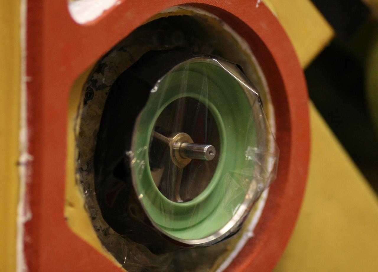
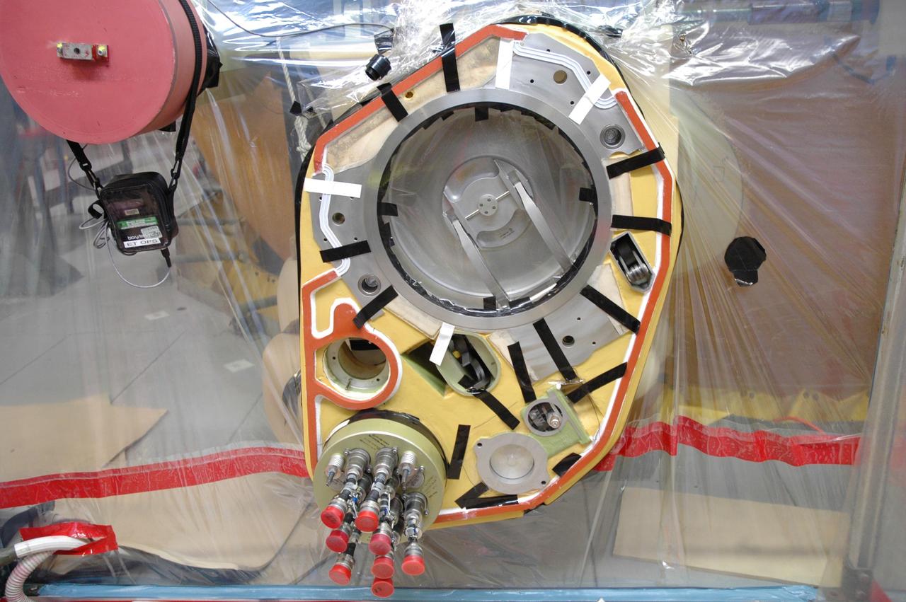
This diagram shows a hydrogen fuel system designed by researchers at the National Advisory Committee for Aeronautics (NACA) Lewis Flight Propulsion Laboratory and installed on a Martin B-57B Canberra aircraft. Lewis researchers accelerated their studies of high energy propellants in the early 1950s. In late 1954, Lewis researchers studied the combustion characteristics of gaseous hydrogen in a turbojet combustor. It was found that the hydrogen provided a very high efficiency. Almost immediately thereafter, Associate Director Abe Silverstein became focused on the possibilities of hydrogen for aircraft propulsion. That fall, Silverstein secured a contract to work with the air force to examine the practicality of liquid hydrogen aircraft. A B-57B Canberra was obtained by the air force especially for this project, referred to as Project Bee. The aircraft was powered by two Wright J65 engines, one of which was modified so that it could be operated using either traditional or liquid hydrogen propellants. The engine and its liquid hydrogen fuel system were tested extensively in the Altitude Wind Tunnel and the Four Burner Area test cells in 1955 and 1956. A B-57B flight program was planned to test the system on an actual aircraft. The aircraft would take off using jet fuel, switch to liquid hydrogen while over Lake Erie, then after burning the hydrogen supply switch back to jet fuel for the landing. The third test flight, in February 1957, was a success, and the ensuing B-57B flights remain the only demonstration of hydrogen-powered aircraft.
CAPE CANAVERAL, Fla. – Inside a test cell in the Vehicle Assembly Building at NASA's Kennedy Space Center, a portion of Atlantis’ external tank is sealed to prevent contamination so that technicians can replace a valve after small dings were found on the sealing surface of the quick disconnect system that handles liquid-hydrogen fuel for the shuttle’s three main engines. The tank will be attached to the twin solid rocket boosters on Aug. 3 for the STS-125 mission, the fifth and final shuttle servicing mission to NASA’s Hubble Space Telescope. During the mission, the crew will install new instruments on the telescope, including the Cosmic Origins Spectrograph and the Wide Field Camera 3. A refurbished Fine Guidance Sensor will replace one unit of three now onboard. Mission specialists will also install new gyroscopes, batteries and thermal blankets on the telescope. Launch is targeted for Oct. 8. Photo credit: NASA/Jim Grossmann
CAPE CANAVERAL, Fla. – Inside a test cell in the Vehicle Assembly Building at NASA's Kennedy Space Center, a portion of Atlantis’ external tank is sealed to prevent contamination so that technicians can remove a valve after small dings were found on the sealing surface of the quick disconnect system that handles liquid-hydrogen fuel for the shuttle’s three main engines. The tank will be attached to the twin solid rocket boosters on Aug. 3 for the STS-125 mission, the fifth and final shuttle servicing mission to NASA’s Hubble Space Telescope. During the mission, the crew will install new instruments on the telescope, including the Cosmic Origins Spectrograph and the Wide Field Camera 3. A refurbished Fine Guidance Sensor will replace one unit of three now onboard. Mission specialists will also install new gyroscopes, batteries and thermal blankets on the telescope. Launch is targeted for Oct. 8. Photo credit: NASA/Dimitri Gerondidakis

Daniel Bernatowicz, Chief of the Advanced Power Systems Branch at the National Aeronautics and Space Administration (NASA) Lewis Research Center, examines a 20-foot section of a solar mirror being fabricated in the Jig Bore Room of the Technical Services Building. NASA Lewis was conducting a wide-ranging effort to explore methods of generating electrical power for spacecraft. One method employed a large parabolic mirror to concentrate the sun’s energy. The mirror had to remain rigid and withstand micrometeoroids, but remain light and compact enough to be easily launched. In 1963 Bernatowicz and his researchers undertook a program to design a solar mirror to work with the Brayton cycle system on a space station. The mirror in this photograph was prepared for a conference on Advanced Technology in Space Power Systems held at Lewis in late August 1966. Lewis experts discussed advances with batteries, fuel cells, isotope and thermoelectric generators, and the SNAP-8 space power system. Lewis was developing several types of solar mirrors to work with a Brayton cycle electric generating system. The mirror’s 12 sections were shaped using a unique forming process developed at Lewis, coated with an epoxy, and plated with aluminum. The mirror concentrated the Sun's rays on a heat storage receiver containing lithium fluoride. This material was heated to produce power in a turbogenerator system, while additional heat was stored for use when the unit was in the Earth's shadow.
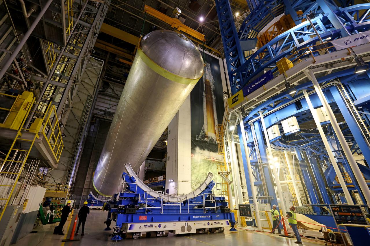
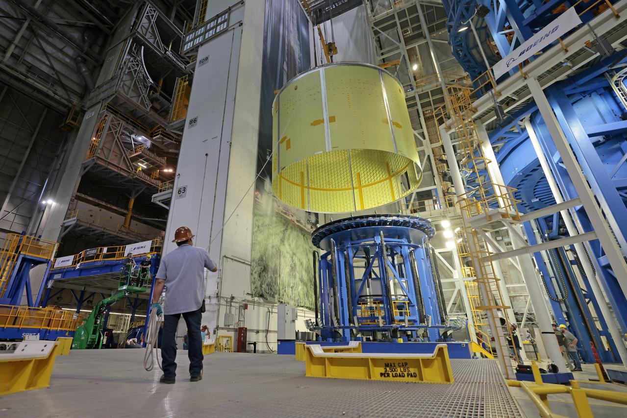
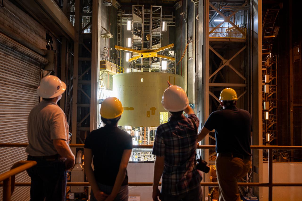
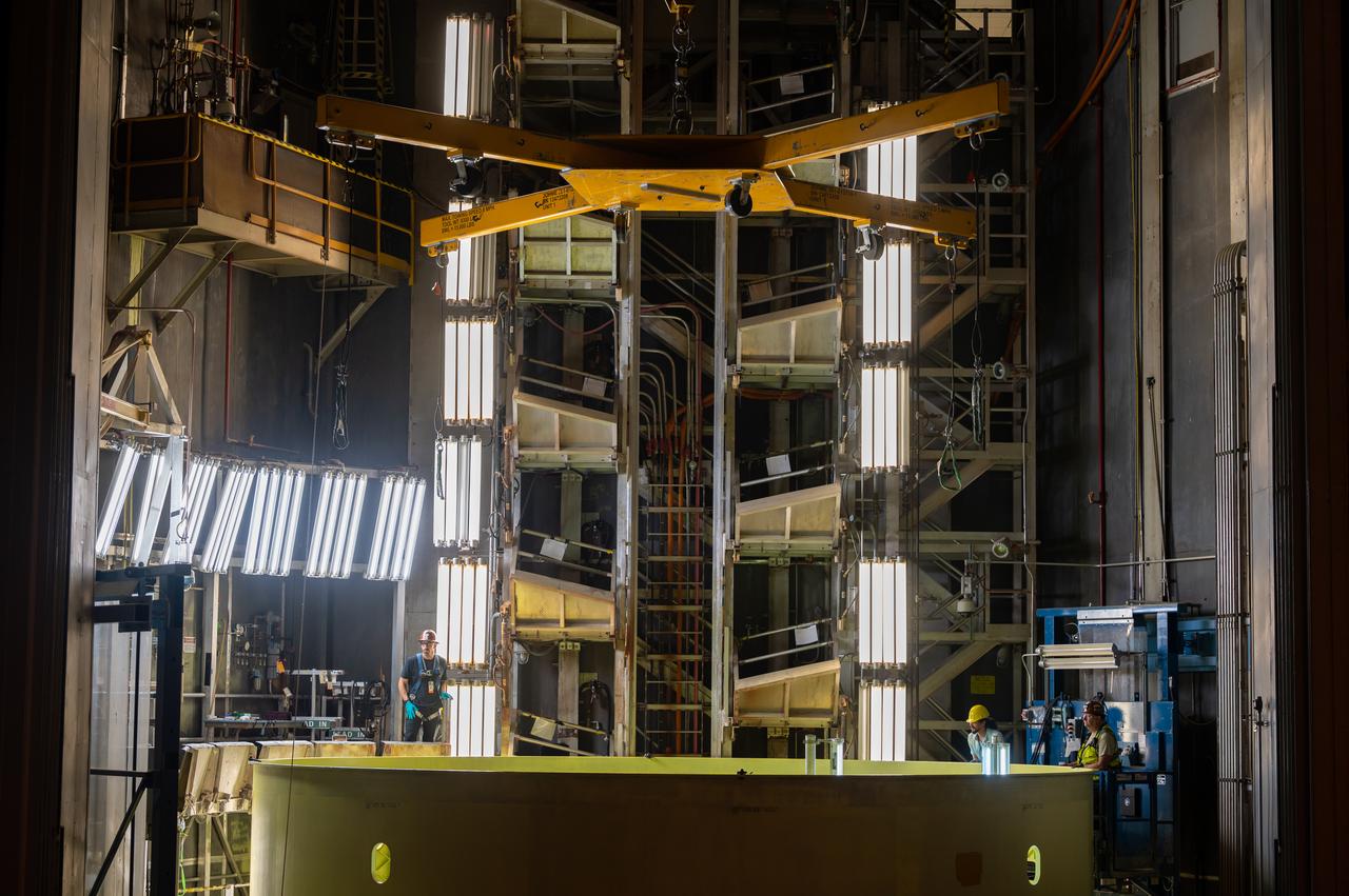
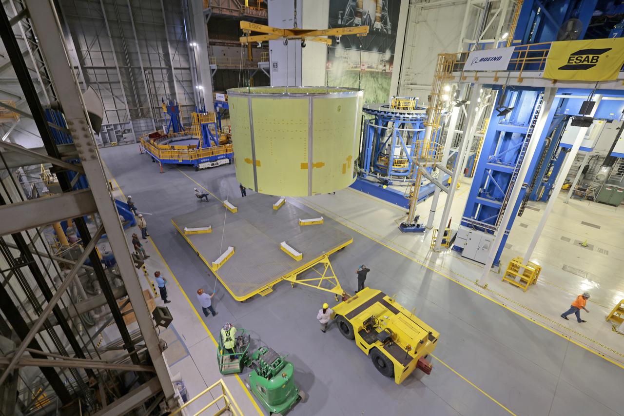
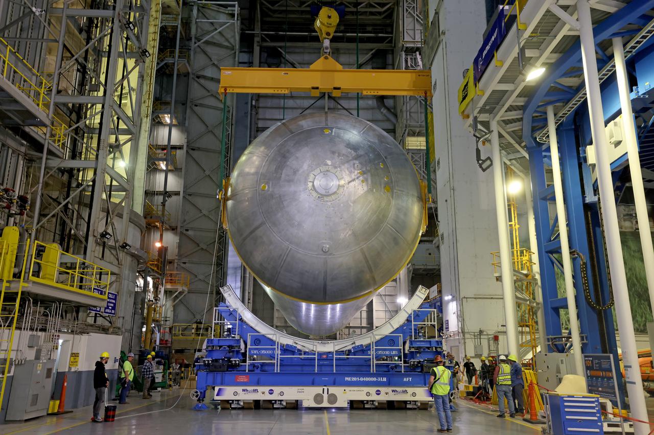
These photos show how teams moved and prepared a liquid hydrogen tank for the SLS (Space Launch System) rocket for priming in the Vertical Assembly Building at NASA’s Michoud Assembly Facility in New Orleans Nov. 14, 2023. The hardware will form part of the core stage for the SLS rocket that will power Artemis III. To prepare the flight hardware for primer, the tank underwent internal cleaning in nearby Cell E in October. Internal cleaning is part of the manufacturing process for the core stage. After testing, both of the stage’s propellant tanks and its dry structures – the elements that do not hold fuel – are cleaned, primed, and readied for the next phase of production Technichians will next sand down and prepare the surface of the tank before coating it in a primer. Primer is applied to the barrel section of the tank by an automated robotic tool, whereas the forward and aft domes are primed manually. The propellant tank is the largest of the five major elements that make up the 212-foot-tall Moon rocket stage. The core stage, along with its four RS-25 engines, produce two million pounds of thrust to help launch NASA’s Orion spacecraft, astronauts, and supplies beyond Earth’s orbit and to the lunar surface for Artemis. Image credit: NASA/Michael DeMocker
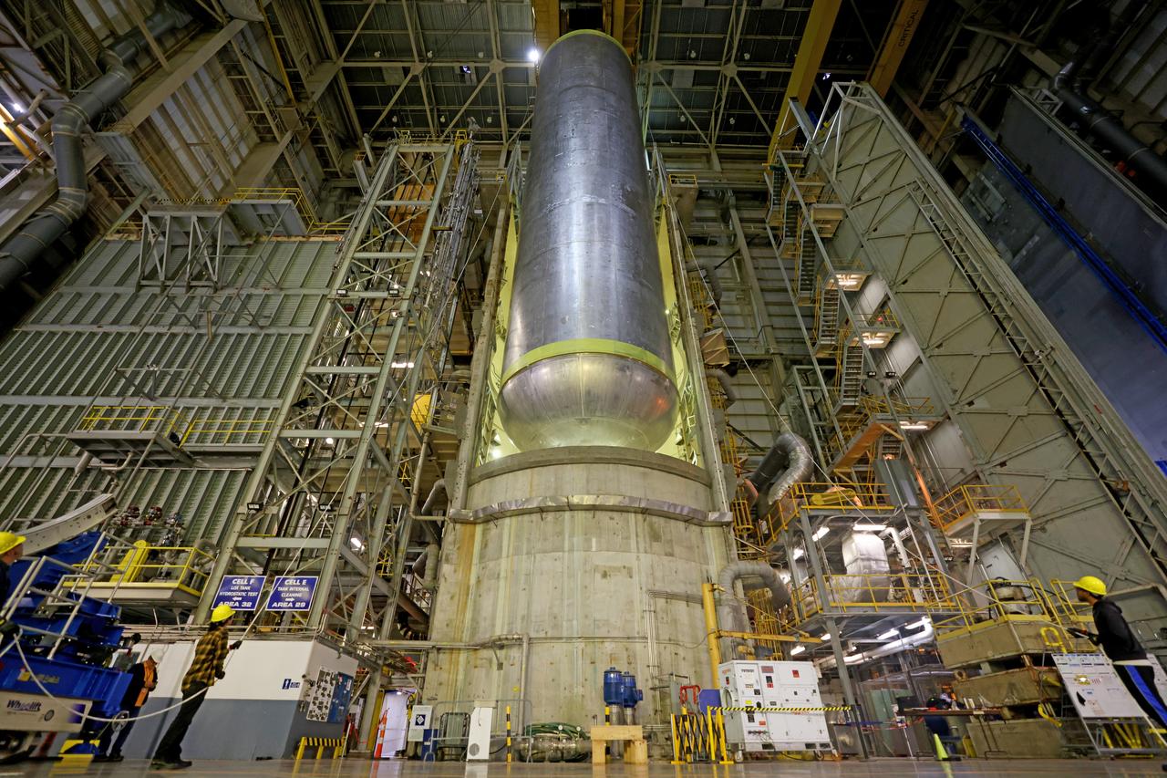
These photos show how teams moved and prepared a liquid hydrogen tank for the SLS (Space Launch System) rocket for priming in the Vertical Assembly Building at NASA’s Michoud Assembly Facility in New Orleans Nov. 14, 2023. The hardware will form part of the core stage for the SLS rocket that will power Artemis III. To prepare the flight hardware for primer, the tank underwent internal cleaning in nearby Cell E in October. Internal cleaning is part of the manufacturing process for the core stage. After testing, both of the stage’s propellant tanks and its dry structures – the elements that do not hold fuel – are cleaned, primed, and readied for the next phase of production Technichians will next sand down and prepare the surface of the tank before coating it in a primer. Primer is applied to the barrel section of the tank by an automated robotic tool, whereas the forward and aft domes are primed manually. The propellant tank is the largest of the five major elements that make up the 212-foot-tall Moon rocket stage. The core stage, along with its four RS-25 engines, produce two million pounds of thrust to help launch NASA’s Orion spacecraft, astronauts, and supplies beyond Earth’s orbit and to the lunar surface for Artemis. Image credit: NASA/Michael DeMocker

These photos show how teams moved and prepared a liquid hydrogen tank for the SLS (Space Launch System) rocket for priming in the Vertical Assembly Building at NASA’s Michoud Assembly Facility in New Orleans Nov. 14, 2023. The hardware will form part of the core stage for the SLS rocket that will power Artemis III. To prepare the flight hardware for primer, the tank underwent internal cleaning in nearby Cell E in October. Internal cleaning is part of the manufacturing process for the core stage. After testing, both of the stage’s propellant tanks and its dry structures – the elements that do not hold fuel – are cleaned, primed, and readied for the next phase of production Technichians will next sand down and prepare the surface of the tank before coating it in a primer. Primer is applied to the barrel section of the tank by an automated robotic tool, whereas the forward and aft domes are primed manually. The propellant tank is the largest of the five major elements that make up the 212-foot-tall Moon rocket stage. The core stage, along with its four RS-25 engines, produce two million pounds of thrust to help launch NASA’s Orion spacecraft, astronauts, and supplies beyond Earth’s orbit and to the lunar surface for Artemis. Image credit: NASA/Michael DeMocker
These photos show how teams moved and prepared a liquid hydrogen tank for the SLS (Space Launch System) rocket for priming in the Vertical Assembly Building at NASA’s Michoud Assembly Facility in New Orleans Nov. 14, 2023. The hardware will form part of the core stage for the SLS rocket that will power Artemis III. To prepare the flight hardware for primer, the tank underwent internal cleaning in nearby Cell E in October. Internal cleaning is part of the manufacturing process for the core stage. After testing, both of the stage’s propellant tanks and its dry structures – the elements that do not hold fuel – are cleaned, primed, and readied for the next phase of production Technichians will next sand down and prepare the surface of the tank before coating it in a primer. Primer is applied to the barrel section of the tank by an automated robotic tool, whereas the forward and aft domes are primed manually. The propellant tank is the largest of the five major elements that make up the 212-foot-tall Moon rocket stage. The core stage, along with its four RS-25 engines, produce two million pounds of thrust to help launch NASA’s Orion spacecraft, astronauts, and supplies beyond Earth’s orbit and to the lunar surface for Artemis. Image credit: NASA/Michael DeMocker
A team of NASA researchers from Marshall Space Flight Center (MSFC) and Dryden Flight Research center have proven that beamed light can be used to power an aircraft, a first-in-the-world accomplishment to the best of their knowledge. Using an experimental custom built radio-controlled model aircraft, the team has demonstrated a system that beams enough light energy from the ground to power the propeller of an aircraft and sustain it in flight. Special photovoltaic arrays on the plane, similar to solar cells, receive the light energy and convert it to electric current to drive the propeller motor. In a series of indoor flights this week at MSFC, a lightweight custom built laser beam was aimed at the airplane `s solar panels. The laser tracks the plane, maintaining power on its cells until the end of the flight when the laser is turned off and the airplane glides to a landing. The laser source demonstration represents the capability to beam more power to a plane so that it can reach higher altitudes and have a greater flight range without having to carry fuel or batteries, enabling an indefinite flight time. The demonstration was a collaborative effort between the Dryden Center at Edward's, California, where the aircraft was designed and built, and MSFC, where integration and testing of the laser and photovoltaic cells was done. Laser power beaming is a promising technology for consideration in new aircraft design and operation, and supports NASA's goals in the development of revolutionary aerospace technologies. Photographed with their invention are (from left to right): David Bushman and Tony Frackowiak, both of Dryden; and MSFC's Robert Burdine.
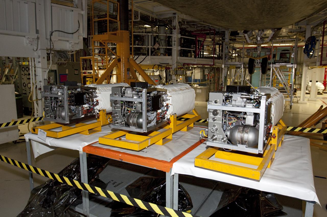
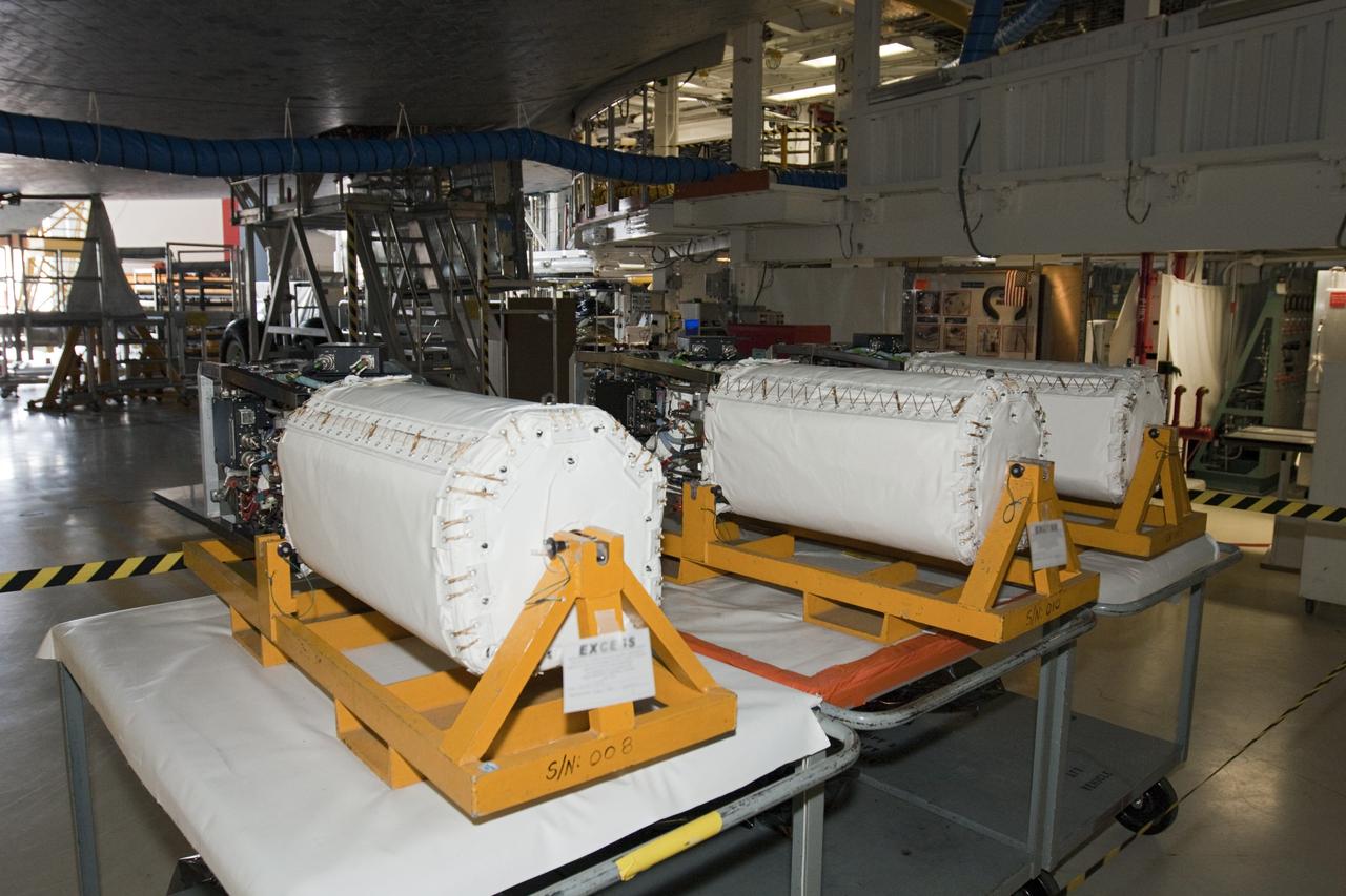
CAPE CANAVERAL, Fla. – Inside Orbiter Processing Facility-1 at NASA’s Kennedy Space Center in Florida, three excessed fuel cells are on a work bench beneath space shuttle Atlantis. The left orbital maneuvering system, or OMS, pod has been installed onto Atlantis. The OMS provided the shuttle with thrust for orbit insertion, rendezvous and deorbit, and could provide up to 1,000 pounds of propellant to the aft reaction control system. The OMS is housed in two independent pods located on each side of the shuttle’s aft fuselage. Each pod contains one OMS engine and the hardware needed to pressurize, store and distribute the propellants to perform the velocity maneuvers. Atlantis’ OMS pods were removed and sent to White Sands Test Facility in New Mexico to be cleaned of residual toxic propellant. The work is part of the Space Shuttle Program’s transition and retirement processing of the space shuttle fleet. A groundbreaking was held Jan. 18 for Atlantis’ future home, a 65,000-square-foot exhibit hall in Shuttle Plaza at the Kennedy Space Center Visitor Complex. Atlantis is scheduled to roll over to the visitor complex in November in preparation for the exhibit’s grand opening in July 2013. For more information, visit http://www.nasa.gov/transition. Photo credit: NASA/Ben Smegelsky
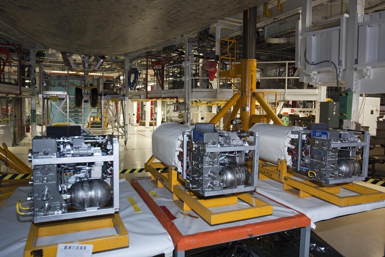
CAPE CANAVERAL, Fla. – Inside Orbiter Processing Facility-1 at NASA’s Kennedy Space Center in Florida, three excessed fuel cells are on a work bench beneath space shuttle Atlantis. The left orbital maneuvering system, or OMS, pod has been installed onto Atlantis. The OMS provided the shuttle with thrust for orbit insertion, rendezvous and deorbit, and could provide up to 1,000 pounds of propellant to the aft reaction control system. The OMS is housed in two independent pods located on each side of the shuttle’s aft fuselage. Each pod contains one OMS engine and the hardware needed to pressurize, store and distribute the propellants to perform the velocity maneuvers. Atlantis’ OMS pods were removed and sent to White Sands Test Facility in New Mexico to be cleaned of residual toxic propellant. The work is part of the Space Shuttle Program’s transition and retirement processing of the space shuttle fleet. A groundbreaking was held Jan. 18 for Atlantis’ future home, a 65,000-square-foot exhibit hall in Shuttle Plaza at the Kennedy Space Center Visitor Complex. Atlantis is scheduled to roll over to the visitor complex in November in preparation for the exhibit’s grand opening in July 2013. For more information, visit http://www.nasa.gov/transition. Photo credit: NASA/Ben Smegelsky
CAPE CANAVERAL, Fla. – Inside Orbiter Processing Facility-1 at NASA’s Kennedy Space Center in Florida, three excessed fuel cells are on a work bench beneath space shuttle Atlantis. The left orbital maneuvering system, or OMS, pod has been installed onto Atlantis. The OMS provided the shuttle with thrust for orbit insertion, rendezvous and deorbit, and could provide up to 1,000 pounds of propellant to the aft reaction control system. The OMS is housed in two independent pods located on each side of the shuttle’s aft fuselage. Each pod contains one OMS engine and the hardware needed to pressurize, store and distribute the propellants to perform the velocity maneuvers. Atlantis’ OMS pods were removed and sent to White Sands Test Facility in New Mexico to be cleaned of residual toxic propellant. The work is part of the Space Shuttle Program’s transition and retirement processing of the space shuttle fleet. A groundbreaking was held Jan. 18 for Atlantis’ future home, a 65,000-square-foot exhibit hall in Shuttle Plaza at the Kennedy Space Center Visitor Complex. Atlantis is scheduled to roll over to the visitor complex in November in preparation for the exhibit’s grand opening in July 2013. For more information, visit http://www.nasa.gov/transition. Photo credit: NASA/Ben Smegelsky
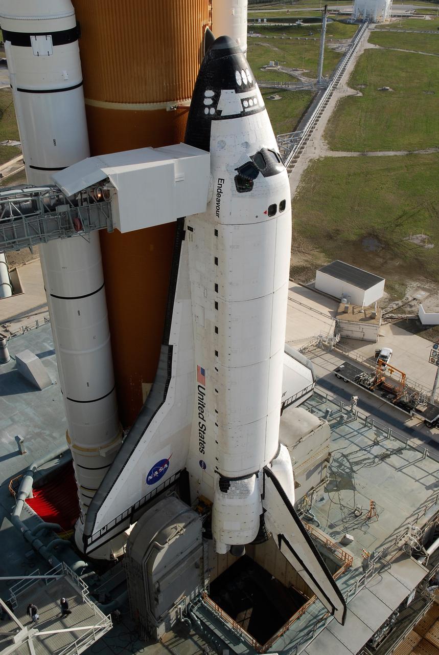
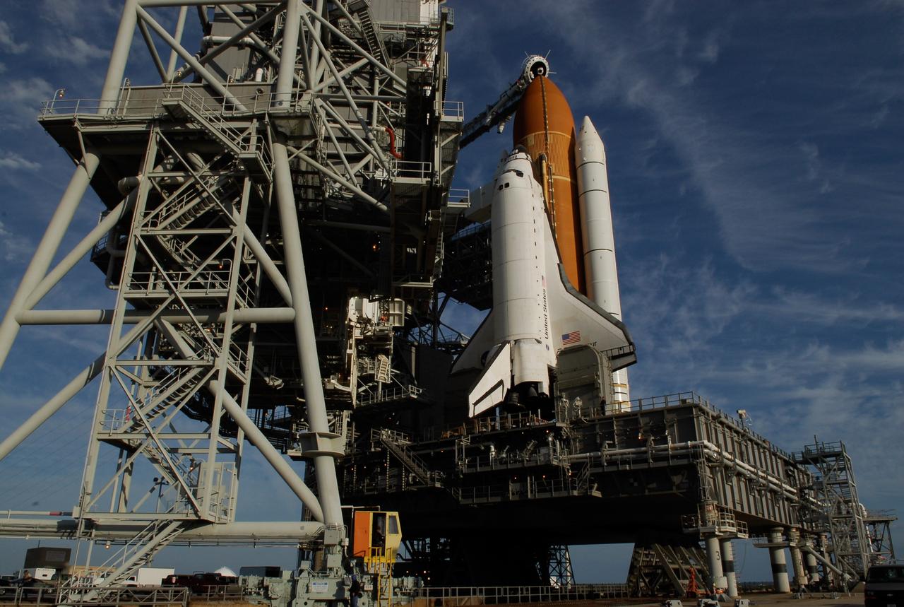
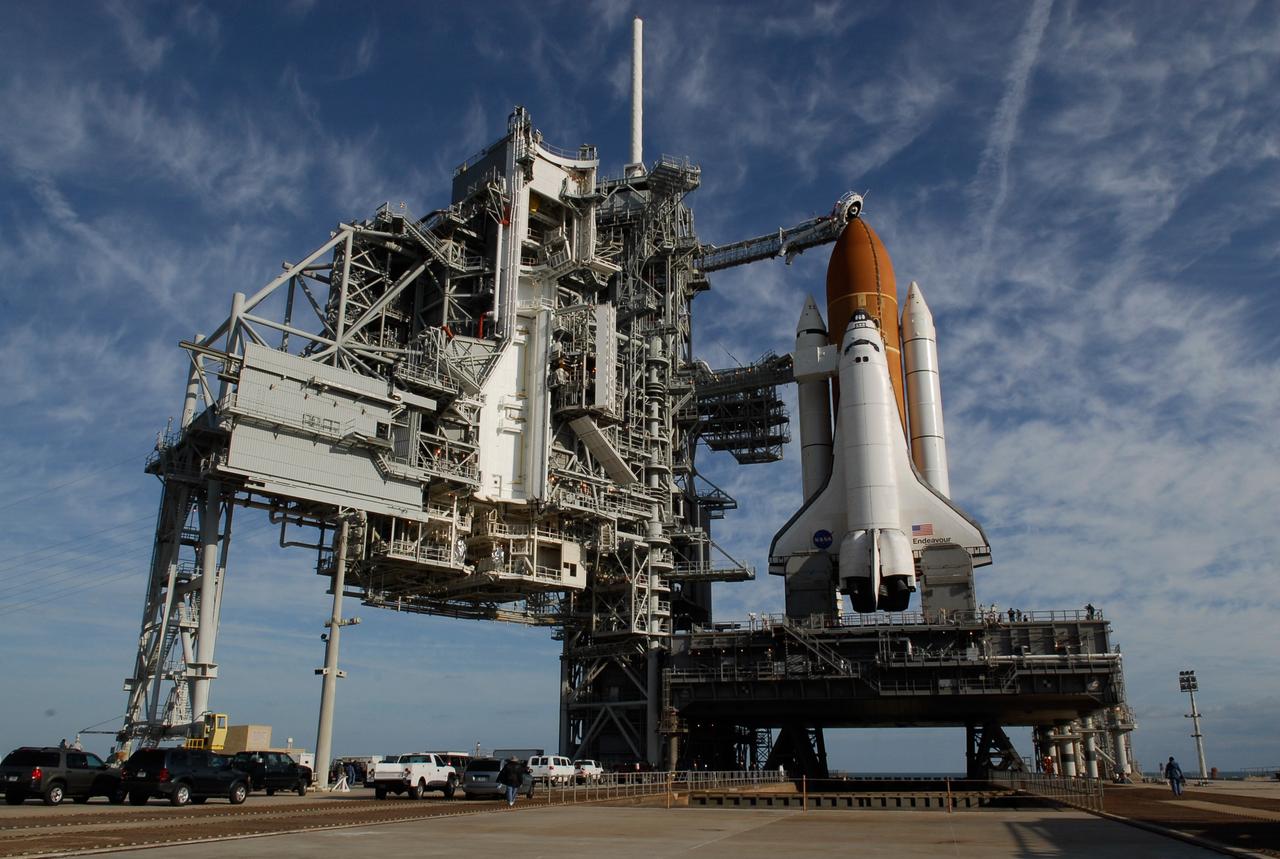
KENNEDY SPACE CENTER, FLA. -- With the rotating service structure rolled away on Launch Pad 39A at NASA's Kennedy Space Center, space shuttle Endeavour is in full view. First motion was at 8:23 a.m. and rollback was complete at 8:55 a.m. Extending toward Endeavour from the left is the orbiter access arm with the White Room at the end, flush against the shuttle. The crew gains access into the orbiter through the White Room. The rotating structure provides protected access to the orbiter for changeout and servicing of payloads at the pad. The structure is supported by a rotating bridge that pivots about a vertical axis on the west side of the pad's flame trench. After the RSS is rolled back, the orbiter is ready for fuel cell activation and external tank cryogenic propellant loading operations. The pad is cleared to the perimeter gate for operations to fill the external tank with about 500,000 gallons of cryogenic propellants used by the shuttle’s main engines. This is done at the pad approximately eight hours before the scheduled launch. Endeavour and its crew will deliver the first section of the Japan Aerospace Exploration Agency's Kibo laboratory and the Canadian Space Agency's two-armed robotic system, Dextre. Launch is scheduled for 2:28 a.m. EDT March 11. Photo credit: NASA/Kim Shiflett
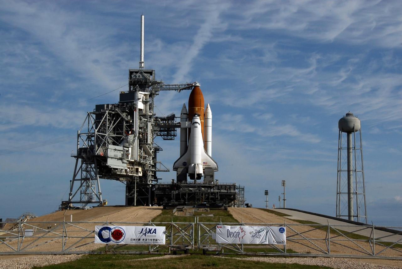
KENNEDY SPACE CENTER, FLA. -- On top of Launch Pad 39A at NASA's Kennedy Space Center, space shuttle Endeavour waits for liftoff on the STS-123 mission. The rotating service structure was rolled back starting at 8:23 a.m. and complete at 8:55 a.m. At far right is the 300,000-gallon water tank that provides the water for sound suppression during liftoff. Signs on the gate across the pad illustrate the primary payloads on the mission: the Japan Aerospace Exploration Agency's Kibo laboratory and the Canadian Space Agency's two-armed robotic system, Dextre. The rotating structure provides protected access to the orbiter for changeout and servicing of payloads at the pad. The structure is supported by a rotating bridge that pivots about a vertical axis on the west side of the pad's flame trench. After the RSS is rolled back, the orbiter is ready for fuel cell activation and external tank cryogenic propellant loading operations. The pad is cleared to the perimeter gate for operations to fill the external tank with about 500,000 gallons of cryogenic propellants used by the shuttle’s main engines. This is done at the pad approximately eight hours before the scheduled launch. Liftoff is scheduled for 2:28 a.m. EDT March 11. Photo credit: NASA/Kim Shiflett

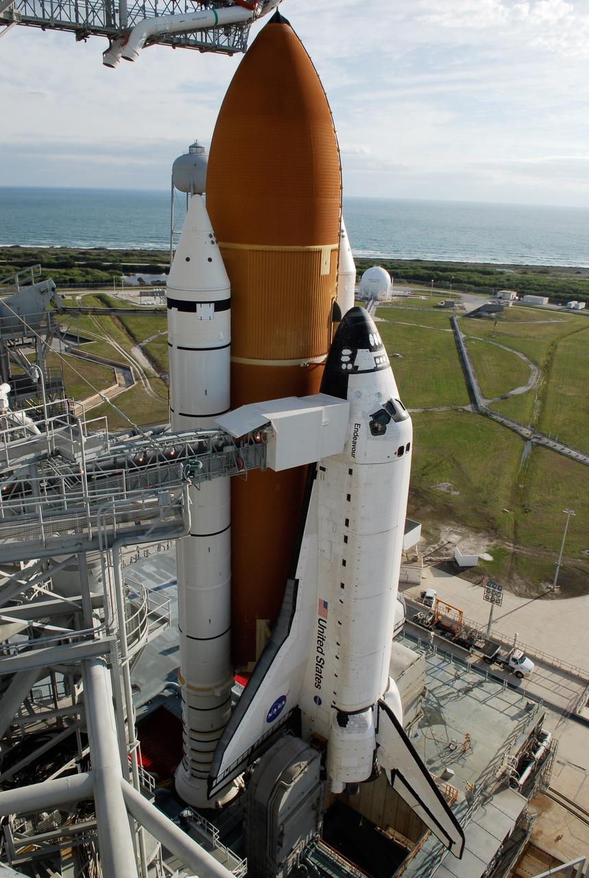
KENNEDY SPACE CENTER, FLA. -- On Launch Pad 39A at NASA's Kennedy Space Center, the rotating service structure has rolled away to uncover space shuttle Endeavour. First motion was at 8:23 a.m. and rollback was complete at 8:55 a.m. Above the orange external tank is seen the "beanie cap" at the end of the gaseous oxygen vent arm, extending from the fixed service structure. Vapors are created as the liquid oxygen in the external tank boil off. The hood vents the gaseous oxygen vapors away from the space shuttle vehicle. The rotating structure provides protected access to the orbiter for changeout and servicing of payloads at the pad. The structure is supported by a rotating bridge that pivots about a vertical axis on the west side of the pad's flame trench. After the RSS is rolled back, the orbiter is ready for fuel cell activation and external tank cryogenic propellant loading operations. The pad is cleared to the perimeter gate for operations to fill the external tank with about 500,000 gallons of cryogenic propellants used by the shuttle’s main engines. This is done at the pad approximately eight hours before the scheduled launch. Endeavour and its crew will deliver the first section of the Japan Aerospace Exploration Agency's Kibo laboratory and the Canadian Space Agency's two-armed robotic system, Dextre. Launch is scheduled for 2:28 a.m. EDT March 11. Photo credit: NASA/Kim Shiflett
KENNEDY SPACE CENTER, FLA. -- With the rotating service structure rolled away on Launch Pad 39A at NASA's Kennedy Space Center, space shuttle Endeavour is in full view. First motion was at 8:23 a.m. and rollback was complete at 8:55 a.m. Behind the shuttle with its large, orange external tank is the blue Atlantic Ocean. Extending toward Endeavour from the left is the orbiter access arm with the White Room at the end, flush against the shuttle. The crew gains access into the orbiter through the White Room. The rotating structure provides protected access to the orbiter for changeout and servicing of payloads at the pad. The structure is supported by a rotating bridge that pivots about a vertical axis on the west side of the pad's flame trench. After the RSS is rolled back, the orbiter is ready for fuel cell activation and external tank cryogenic propellant loading operations. The pad is cleared to the perimeter gate for operations to fill the external tank with about 500,000 gallons of cryogenic propellants used by the shuttle’s main engines. This is done at the pad approximately eight hours before the scheduled launch. Endeavour and its crew will deliver the first section of the Japan Aerospace Exploration Agency's Kibo laboratory and the Canadian Space Agency's two-armed robotic system, Dextre. Launch is scheduled for 2:28 a.m. EDT March 11. Photo credit: NASA/Kim Shiflett
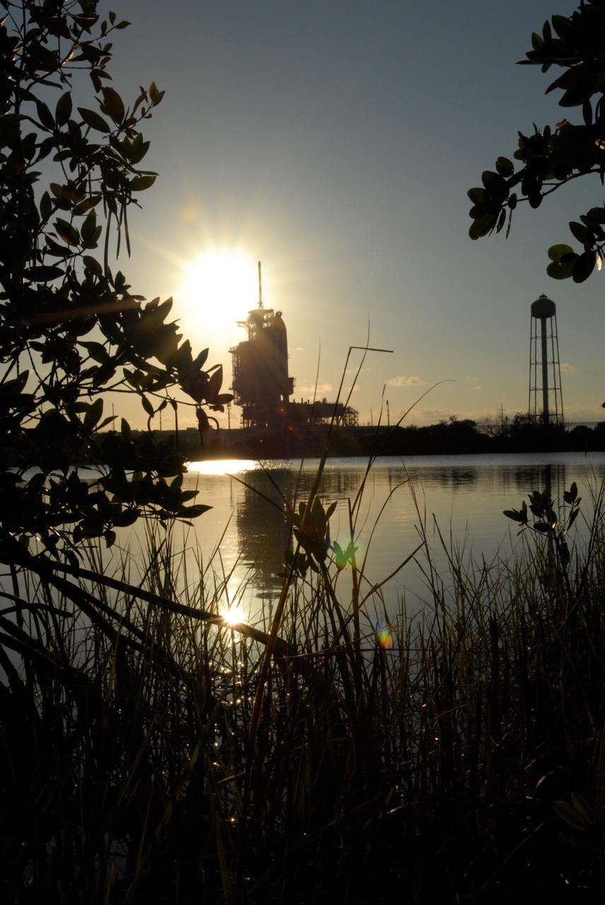
CAPE CANAVERAL, Fla. -- The setting sun backlights space shuttle Discovery on Launch Pad 39A at NASA's Kennedy Space Center just before rollback of the rotating service structure in preparation for launch on the STS-124 mission. The structure provides protected access to the shuttle for changeout and servicing of payloads at the pad. It is supported by a rotating bridge that pivots on a vertical axis on the west side of the pad's flame trench. After the RSS is rolled back, the orbiter is ready for fuel cell activation and external tank cryogenic propellant loading operations. The pad is cleared to the perimeter gate for operations to fill the external tank with about 500,000 gallons of cryogenic propellants used by the shuttle’s main engines. This is done at the pad approximately eight hours before the scheduled launch. The STS-124 mission is the second of three flights launching components to complete the Japan Aerospace Exploration Agency's Kibo laboratory. The shuttle crew will install Kibo's large Japanese Pressurized Module and its remote manipulator system, or RMS. The 14-day flight includes three spacewalks. Launch is scheduled for 5:02 p.m. May 31. Photo credit: NASA/Troy Cryder

KENNEDY SPACE CENTER, FLA. -- From across the marsh next to Launch Pad 39A at NASA's Kennedy Space Center, space shuttle Endeavour is in full view after rollback of the rotating service structure. First motion was at 8:23 a.m. and rollback was complete at 8:55 a.m. At far right is the 300,000-gallon water tank that provides the water for sound suppression during liftoff. The rotating structure provides protected access to the orbiter for changeout and servicing of payloads at the pad. The structure is supported by a rotating bridge that pivots about a vertical axis on the west side of the pad's flame trench. After the RSS is rolled back, the orbiter is ready for fuel cell activation and external tank cryogenic propellant loading operations. The pad is cleared to the perimeter gate for operations to fill the external tank with about 500,000 gallons of cryogenic propellants used by the shuttle’s main engines. This is done at the pad approximately eight hours before the scheduled launch. Endeavour and its crew will deliver the first section of the Japan Aerospace Exploration Agency's Kibo laboratory and the Canadian Space Agency's two-armed robotic system, Dextre. Launch is scheduled for 2:28 a.m. EDT March 11. Photo credit: NASA/Kim Shiflett
KENNEDY SPACE CENTER, FLA. -- On Launch Pad 39A at NASA's Kennedy Space Center, the rotating service structure is rolling on its axis to uncover space shuttle Endeavour. First motion was at 8:23 a.m. and rollback was complete at 8:55 a.m. Above the orange external tank is seen the "beanie cap" at the end of the gaseous oxygen vent arm, extending from the fixed service structure. Vapors are created as the liquid oxygen in the external tank boil off. The hood vents the gaseous oxygen vapors away from the space shuttle vehicle. The rotating structure provides protected access to the orbiter for changeout and servicing of payloads at the pad. The structure is supported by a rotating bridge that pivots about a vertical axis on the west side of the pad's flame trench. After the RSS is rolled back, the orbiter is ready for fuel cell activation and external tank cryogenic propellant loading operations. The pad is cleared to the perimeter gate for operations to fill the external tank with about 500,000 gallons of cryogenic propellants used by the shuttle’s main engines. This is done at the pad approximately eight hours before the scheduled launch. Endeavour and its crew will deliver the first section of the Japan Aerospace Exploration Agency's Kibo laboratory and the Canadian Space Agency's two-armed robotic system, Dextre. Launch is scheduled for 2:28 a.m. EDT March 11. Photo credit: NASA/Kim Shiflett
KENNEDY SPACE CENTER, FLA. -- On Launch Pad 39A at NASA's Kennedy Space Center, the rotating service structure is rolling on its axis to uncover space shuttle Endeavour. First motion was at 8:23 a.m. and rollback was complete at 8:55 a.m. The structure provides protected access to the orbiter for changeout and servicing of payloads at the pad. The structure is supported by a rotating bridge that pivots about a vertical axis on the west side of the pad's flame trench. After the RSS is rolled back, the orbiter is ready for fuel cell activation and external tank cryogenic propellant loading operations. The pad is cleared to the perimeter gate for operations to fill the external tank with about 500,000 gallons of cryogenic propellants used by the shuttle’s main engines. This is done at the pad approximately eight hours before the scheduled launch. Endeavour and its crew will deliver the first section of the Japan Aerospace Exploration Agency's Kibo laboratory and the Canadian Space Agency's two-armed robotic system, Dextre. Launch is scheduled for 2:28 a.m. EDT March 11. Photo credit: NASA/Kim Shiflett
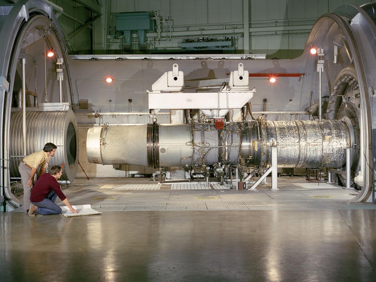
A refanned Pratt and Whitney JT-8D-109 turbofan engine installed in Cell 4 of the Propulsion Systems Laboratory at the National Aeronautics and Space Administration (NASA) Lewis Research Center. NASA Lewis’ Refan Program sought to demonstrate that noise reduction modifications could be applied to existing aircraft engines with minimal costs and without diminishing the engine’s performance or integrity. At the time, Pratt and Whitney’s JT-8D turbofans were one of the most widely used engines in the commercial airline industry. The engines powered Boeing’s 727 and 737 and McDonnell Douglas’ DC-9 aircraft. Pratt and Whitney worked with the airline manufacturers on a preliminary study that verified feasibility of replacing the JT-8D’s two-stage fan with a larger single-stage fan. The new fan slowed the engine’s exhaust, which significantly reduced the amount of noise it generated. Booster stages were added to maintain the proper level of airflow through the engine. Pratt and Whitney produced six of the modified engines, designated JT-8D-109, and performed the initial testing. One of the JT-8D-109 engines, seen here, was tested in simulated altitude conditions in NASA Lewis’ Propulsion Systems Laboratory. The Refan engine was ground-tested on an actual aircraft before making a series of flight tests on 727 and DC-9 aircraft in early 1976. The Refan Program reduced the JT-8D’s noise by 50 percent while increasing the fuel efficiency. The retro-fit kits were estimated to cost between $1 million and $1.7 million per aircraft.
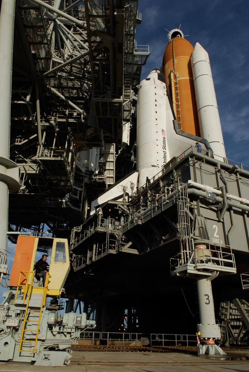
CAPE CANAVERAL, Fla. -- On Launch Pad 39A at NASA's Kennedy Space Center, the rotating service structure, or RSS, is rolling on its axis to uncover space shuttle Discovery in preparation for launch on the STS-124 mission. Support for the outer end of the bridge is provided by two eight-wheel, motor-driven trucks (one is seen at bottom left) that move along circular twin rails installed flush with the pad surface. First motion was at 8:33 p.m. and rollback was complete at 9:07 p.m. The structure provides protected access to the shuttle for changeout and servicing of payloads at the pad. It is supported by a rotating bridge that pivots on a vertical axis on the west side of the pad's flame trench. After the RSS is rolled back, the orbiter is ready for fuel cell activation and external tank cryogenic propellant loading operations. The pad is cleared to the perimeter gate for operations to fill the external tank with about 500,000 gallons of cryogenic propellants used by the shuttle’s main engines. This is done at the pad approximately eight hours before the scheduled launch. The STS-124 mission is the second of three flights launching components to complete the Japan Aerospace Exploration Agency's Kibo laboratory. The shuttle crew will install Kibo's large Japanese Pressurized Module and its remote manipulator system, or RMS. The 14-day flight includes three spacewalks. Launch is scheduled for 5:02 p.m. May 31. Photo credit: NASA/Troy Cryder
KENNEDY SPACE CENTER, FLA. -- On Launch Pad 39A at NASA's Kennedy Space Center, rollback of the rotating service structure (at left) reveals space shuttle Endeavour atop the mobile launcher platform. First motion was at 8:23 a.m. and rollback was complete at 8:55 a.m. Above the orange external tank is seen the "beanie cap" at the end of the gaseous oxygen vent arm, extending from the fixed service structure. Vapors are created as the liquid oxygen in the external tank boil off. The hood vents the gaseous oxygen vapors away from the space shuttle vehicle. Below is the orbiter access arm with the White Room at the end, flush against the shuttle. The crew gains access into the orbiter through the White Room. On either side of the main engines and below the wings are the tail service masts, which provide several umbilical connections to the orbiter, including a liquid-oxygen line through one and a liquid-hydrogen line through another. The rotating structure provides protected access to the orbiter for changeout and servicing of payloads at the pad. The structure is supported by a rotating bridge that pivots about a vertical axis on the west side of the pad's flame trench. After the RSS is rolled back, the orbiter is ready for fuel cell activation and external tank cryogenic propellant loading operations. The pad is cleared to the perimeter gate for operations to fill the external tank with about 500,000 gallons of cryogenic propellants used by the shuttle’s main engines. This is done at the pad approximately eight hours before the scheduled launch. Endeavour and its crew will deliver the first section of the Japan Aerospace Exploration Agency's Kibo laboratory and the Canadian Space Agency's two-armed robotic system, Dextre. Launch is scheduled for 2:28 a.m. EDT March 11. Photo credit: NASA/Kim Shiflett
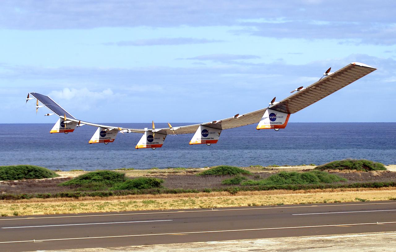
NASA's Helios Prototype aircraft taking off from the Pacific Missile Range Facility, Kauai, Hawaii, for the record flight. As a follow-on to the Centurion (and earlier Pathfinder and Pathfinder-Plus) aircraft, the solar-powered Helios Prototype is the latest and largest example of a slow-flying ultralight flying wing designed for long-duration, high-altitude Earth science or telecommunications relay missions in the stratosphere. Developed by AeroVironment, Inc., of Monrovia, California, under NASA's Environmental Research Aircraft and Sensor Technology (ERAST) project, the unique craft is intended to demonstrate two key missions: the ability to reach and sustain horizontal flight at 100,000 feet altitude on a single-day flight in 2001, and to maintain flight above 50,000 feet altitude for at least four days in 2003, with the aid of a regenerative fuel cell-based energy storage system now in development. Both of these missions will be powered by electricity derived from non-polluting solar energy. The Helios Prototype is an enlarged version of the Centurion flying wing, which flew a series of test flights at NASA's Dryden Flight Research Center in late 1998. The craft has a wingspan of 247 feet, 41 feet greater than the Centurion, 2 1/2 times that of its solar-powered Pathfinder flying wing, and longer than the wingspans of either the Boeing 747 jetliner or Lockheed C-5 transport aircraft. The remotely piloted, electrically powered Helios Prototype went aloft on its maiden low-altitude checkout flight Sept. 8, 1999, over Rogers Dry Lake adjacent to NASA's Dryden Flight Research Center in the Southern California desert. The initial flight series was flown on battery power as a risk-reduction measure. In all, six flights were flown in the Helios Protoype's initial development series. In upgrading the Centurion to the Helios Prototype configuration, AeroVironment added a sixth wing section and a fifth landing gear pod, among other improvements. The additional wingsp
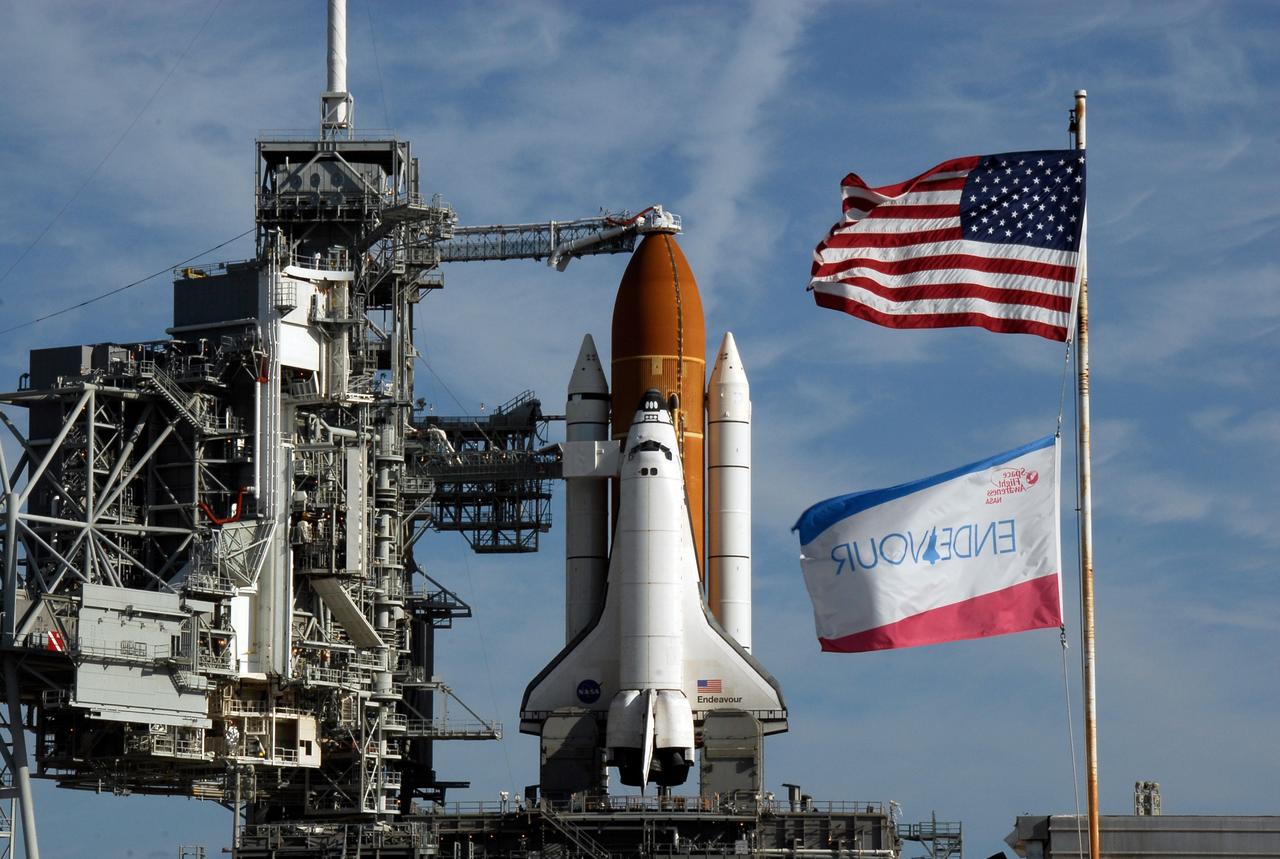
KENNEDY SPACE CENTER, FLA. -- Flags wave near Launch Pad 39A where space shuttle Endeavour waits for liftoff. The rotating service structure was rolled back starting at 8:23 a.m. and complete at 8:55 a.m. Above the orange external tank is seen the "beanie cap" at the end of the gaseous oxygen vent arm, extending from the fixed service structure. Vapors are created as the liquid oxygen in the external tank boil off. The hood vents the gaseous oxygen vapors away from the space shuttle vehicle. Below is the orbiter access arm with the White Room at the end, flush against the shuttle. The crew gains access into the orbiter through the White Room. The rotating structure provides protected access to the orbiter for changeout and servicing of payloads at the pad. The structure is supported by a rotating bridge that pivots about a vertical axis on the west side of the pad's flame trench. After the RSS is rolled back, the orbiter is ready for fuel cell activation and external tank cryogenic propellant loading operations. The pad is cleared to the perimeter gate for operations to fill the external tank with about 500,000 gallons of cryogenic propellants used by the shuttle’s main engines. This is done at the pad approximately eight hours before the scheduled launch. Endeavour and its crew will deliver the first section of the Japan Aerospace Exploration Agency's Kibo laboratory and the Canadian Space Agency's two-armed robotic system, Dextre. Launch is scheduled for 2:28 a.m. EDT March 11. Photo credit: NASA/Kim Shiflett
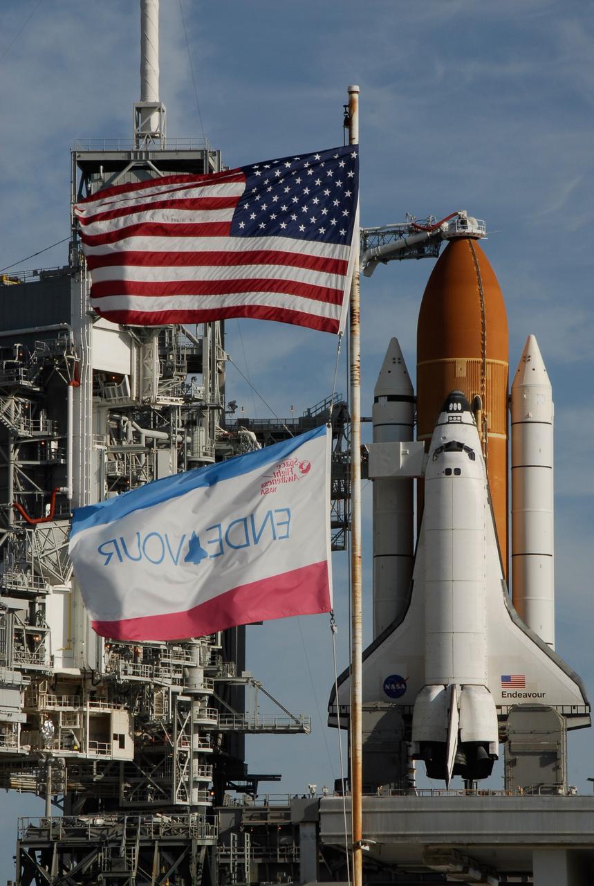
KENNEDY SPACE CENTER, FLA. -- Flags wave near Launch Pad 39A where space shuttle Endeavour waits for liftoff. The rotating service structure was rolled back starting at 8:23 a.m. and complete at 8:55 a.m. Above the orange external tank is seen the "beanie cap" at the end of the gaseous oxygen vent arm, extending from the fixed service structure. Vapors are created as the liquid oxygen in the external tank boil off. The hood vents the gaseous oxygen vapors away from the space shuttle vehicle. Below is the orbiter access arm with the White Room at the end, flush against the shuttle. The crew gains access into the orbiter through the White Room. The rotating structure provides protected access to the orbiter for changeout and servicing of payloads at the pad. The structure is supported by a rotating bridge that pivots about a vertical axis on the west side of the pad's flame trench. After the RSS is rolled back, the orbiter is ready for fuel cell activation and external tank cryogenic propellant loading operations. The pad is cleared to the perimeter gate for operations to fill the external tank with about 500,000 gallons of cryogenic propellants used by the shuttle’s main engines. This is done at the pad approximately eight hours before the scheduled launch. Endeavour and its crew will deliver the first section of the Japan Aerospace Exploration Agency's Kibo laboratory and the Canadian Space Agency's two-armed robotic system, Dextre. Launch is scheduled for 2:28 a.m. EDT March 11. Photo credit: NASA/Kim Shiflett
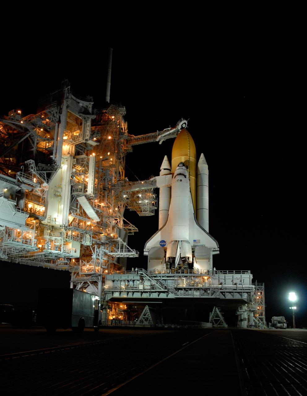
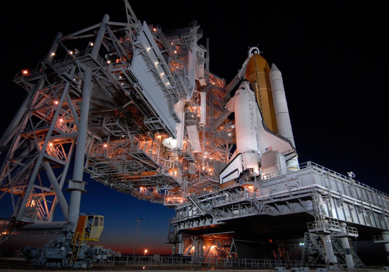
CAPE CANAVERAL, Fla. -- Against the dark sky, lights bathe space shuttle Discovery, revealed after rollback of the rotating service structure in preparation for launch on the STS-124 mission. First motion was at 8:33 p.m. and rollback was complete at 9:07 p.m. The rotating structure provides protected access to the shuttle for changeout and servicing of payloads at the pad. It is supported by a rotating bridge that pivots on a vertical axis on the west side of the pad's flame trench. After the RSS is rolled back, the orbiter is ready for fuel cell activation and external tank cryogenic propellant loading operations. The pad is cleared to the perimeter gate for operations to fill the external tank with about 500,000 gallons of cryogenic propellants used by the shuttle’s main engines. This is done at the pad approximately eight hours before the scheduled launch. Above the orange external tank is the oxygen vent hood, called the "beanie cap," at the end of the gaseous oxygen vent arm extending from the fixed service structure. Vapors are created as the liquid oxygen in the external tank boil off. The hood vents the gaseous oxygen vapors away from the space shuttle vehicle. Below is the orbiter access arm with the White Room at the end, flush against the shuttle. The White Room provides access into the shuttle. The STS-124 mission is the second of three flights launching components to complete the Japan Aerospace Exploration Agency's Kibo laboratory. The shuttle crew will install Kibo's large Japanese Pressurized Module and its remote manipulator system, or RMS. The 14-day flight includes three spacewalks. Launch is scheduled for 5:02 p.m. May 31. Photo credit: NASA/Troy Cryder
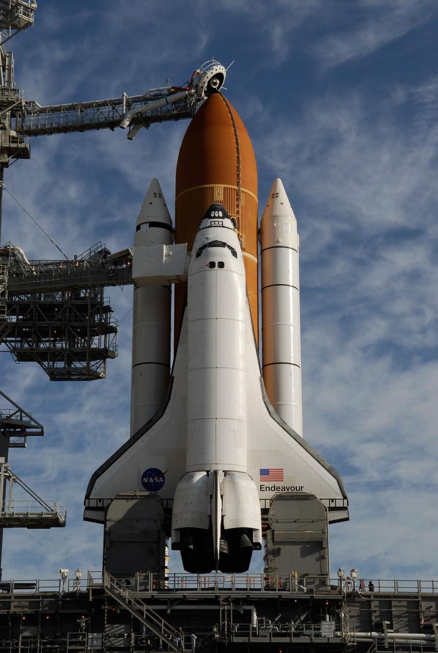
KENNEDY SPACE CENTER, FLA. -- On Launch Pad 39A at NASA's Kennedy Space Center, rollback of the rotating service structure reveals space shuttle Endeavour atop the mobile launcher platform. First motion was at 8:23 a.m. and rollback was complete at 8:55 a.m. Above the orange external tank is seen the "beanie cap" at the end of the gaseous oxygen vent arm, extending from the fixed service structure. Vapors are created as the liquid oxygen in the external tank boil off. The hood vents the gaseous oxygen vapors away from the space shuttle vehicle. Below is the orbiter access arm with the White Room at the end, flush against the shuttle. The crew gains access into the orbiter through the White Room. On either side of the main engines and below the wings are the tail service masts, which provide several umbilical connections to the orbiter, including a liquid-oxygen line through one and a liquid-hydrogen line through another. The rotating structure provides protected access to the orbiter for changeout and servicing of payloads at the pad. The structure is supported by a rotating bridge that pivots about a vertical axis on the west side of the pad's flame trench. After the RSS is rolled back, the orbiter is ready for fuel cell activation and external tank cryogenic propellant loading operations. The pad is cleared to the perimeter gate for operations to fill the external tank with about 500,000 gallons of cryogenic propellants used by the shuttle’s main engines. This is done at the pad approximately eight hours before the scheduled launch. Endeavour and its crew will deliver the first section of the Japan Aerospace Exploration Agency's Kibo laboratory and the Canadian Space Agency's two-armed robotic system, Dextre. Launch is scheduled for 2:28 a.m. EDT March 11. Photo credit: NASA/Kim Shiflett
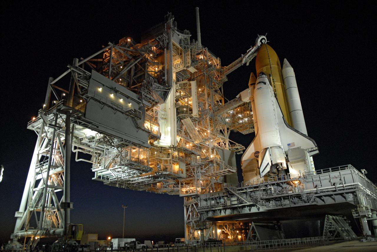
CAPE CANAVERAL, Fla. -- On Launch Pad 39A at NASA's Kennedy Space Center, the rotating service structure, or RSS, has rolled back on its axis to uncover space shuttle Discovery, lighted against the night sky, in preparation for launch on the STS-124 mission. Support for the outer end of the bridge is provided by two eight-wheel, motor-driven trucks (one is seen at bottom left) that move along circular twin rails installed flush with the pad surface. First motion was at 8:33 p.m. and rollback was complete at 9:07 p.m. The structure provides protected access to the shuttle for changeout and servicing of payloads at the pad. It is supported by a rotating bridge that pivots on a vertical axis on the west side of the pad's flame trench. After the RSS is rolled back, the orbiter is ready for fuel cell activation and external tank cryogenic propellant loading operations. The pad is cleared to the perimeter gate for operations to fill the external tank with about 500,000 gallons of cryogenic propellants used by the shuttle’s main engines. This is done at the pad approximately eight hours before the scheduled launch. Above the orange external tank is the oxygen vent hood, called the "beanie cap," at the end of the gaseous oxygen vent arm extending from the fixed service structure. Vapors are created as the liquid oxygen in the external tank boil off. The hood vents the gaseous oxygen vapors away from the space shuttle vehicle. Below is the orbiter access arm with the White Room at the end, flush against the shuttle. The White Room provides access into the shuttle. The STS-124 mission is the second of three flights launching components to complete the Japan Aerospace Exploration Agency's Kibo laboratory. The shuttle crew will install Kibo's large Japanese Pressurized Module and its remote manipulator system, or RMS. The 14-day flight includes three spacewalks. Launch is scheduled for 5:02 p.m. May 31. Photo credit: NASA/Troy Cryder
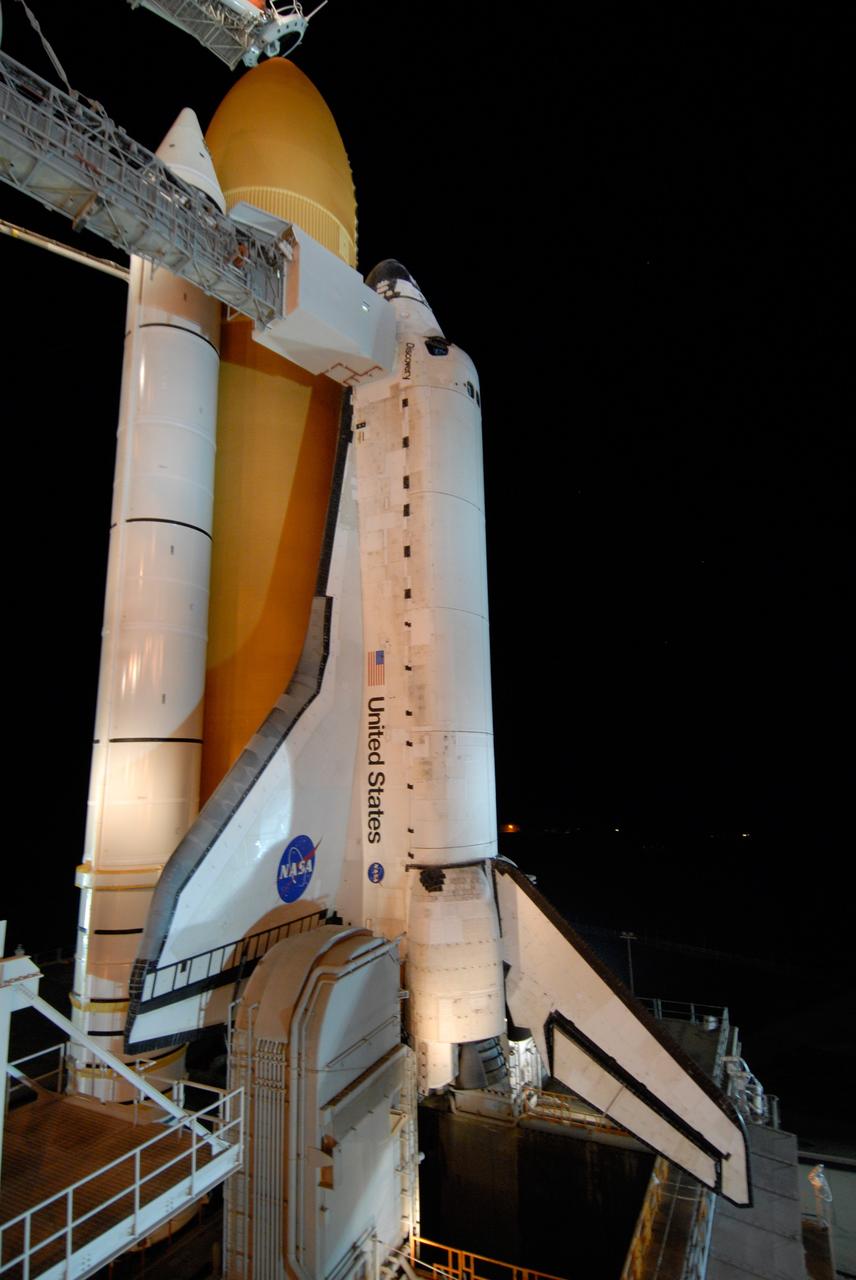
CAPE CANAVERAL, Fla. -- Bathed in lights surrounding Launch Pad 39A and its structures at NASA's Kennedy Space Center, space shuttle Discovery is poised for launch on the STS-124 mission after rollback of the rotating service structure. First motion was at 8:33 p.m. and rollback was complete at 9:07 p.m. The structure provides protected access to the shuttle for changeout and servicing of payloads at the pad. It is supported by a rotating bridge that pivots on a vertical axis on the west side of the pad's flame trench. After the RSS is rolled back, the orbiter is ready for fuel cell activation and external tank cryogenic propellant loading operations. The pad is cleared to the perimeter gate for operations to fill the external tank with about 500,000 gallons of cryogenic propellants used by the shuttle’s main engines. This is done at the pad approximately eight hours before the scheduled launch. Behind the shuttle is the orange external tank and the two solid rocket boosters (only one seen here). Beneath the shuttle's starboard wing is one of two tail service masts, which provide several umbilical connections to the orbiter, including a liquid-oxygen line through one and a liquid-hydrogen line through another. The STS-124 mission is the second of three flights launching components to complete the Japan Aerospace Exploration Agency's Kibo laboratory. The shuttle crew will install Kibo's large Japanese Pressurized Module and its remote manipulator system, or RMS. The 14-day flight includes three spacewalks. Launch is scheduled for 5:02 p.m. May 31. Photo credit: NASA/Troy Cryder
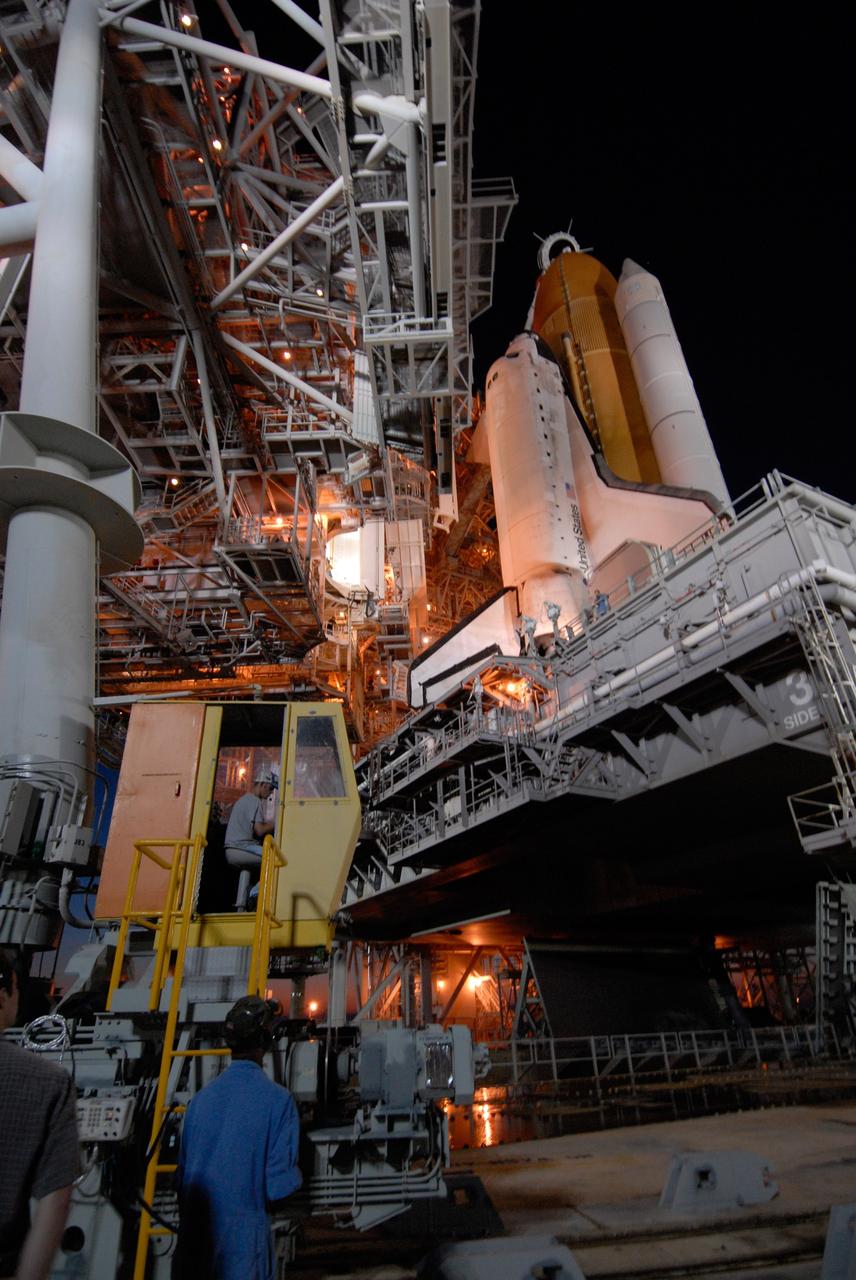
CAPE CANAVERAL, Fla. -- On Launch Pad 39A at NASA's Kennedy Space Center, the rotating service structure begins rolling on its axis to uncover space shuttle Discovery in preparation for launch on the STS-124 mission. Support for the outer end of the bridge is provided by two eight-wheel, motor-driven trucks (one is seen at bottom left) that move along circular twin rails installed flush with the pad surface. First motion was at 8:33 p.m. and rollback was complete at 9:07 p.m. The structure provides protected access to the shuttle for changeout and servicing of payloads at the pad. It is supported by a rotating bridge that pivots on a vertical axis on the west side of the pad's flame trench. After the RSS is rolled back, the orbiter is ready for fuel cell activation and external tank cryogenic propellant loading operations. The pad is cleared to the perimeter gate for operations to fill the external tank with about 500,000 gallons of cryogenic propellants used by the shuttle’s main engines. This is done at the pad approximately eight hours before the scheduled launch. The STS-124 mission is the second of three flights launching components to complete the Japan Aerospace Exploration Agency's Kibo laboratory. The shuttle crew will install Kibo's large Japanese Pressurized Module and its remote manipulator system, or RMS. The 14-day flight includes three spacewalks. Launch is scheduled for 5:02 p.m. May 31. Photo credit: NASA/Troy Cryder
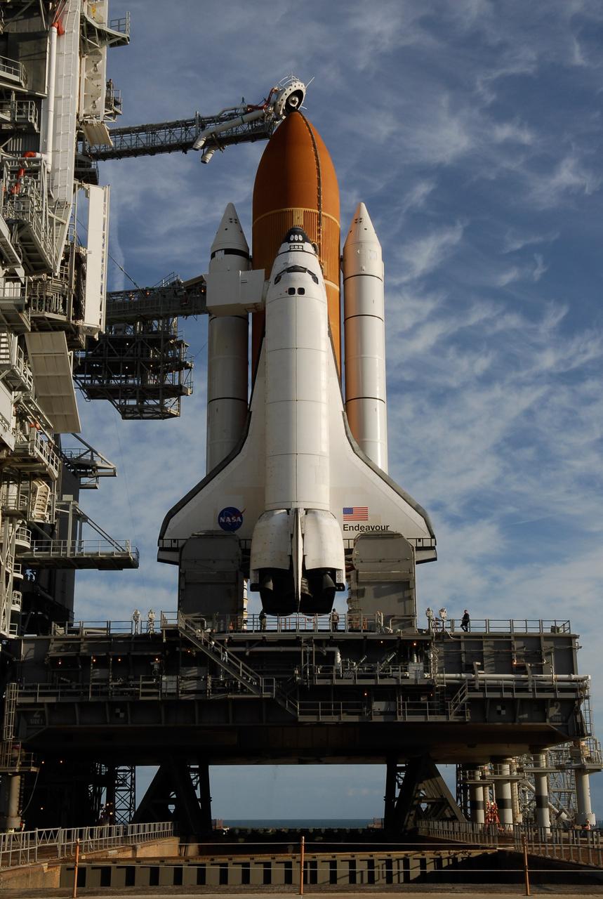
KENNEDY SPACE CENTER, FLA. -- On Launch Pad 39A at NASA's Kennedy Space Center, the rotating service structure has rolled away to uncover space shuttle Endeavour, resting on the mobile launcher platform. First motion was at 8:23 a.m. and rollback was complete at 8:55 a.m. Above the orange external tank is seen the "beanie cap" at the end of the gaseous oxygen vent arm, extending from the fixed service structure. Vapors are created as the liquid oxygen in the external tank boil off. The hood vents the gaseous oxygen vapors away from the space shuttle vehicle. Below is the orbiter access arm with the White Room at the end, flush against the shuttle. The crew gains access into the orbiter through the White Room. On either side of the main engines and below the wings are the tail service masts, which provide several umbilical connections to the orbiter, including a liquid-oxygen line through one and a liquid-hydrogen line through another. The rotating structure provides protected access to the orbiter for changeout and servicing of payloads at the pad. The structure is supported by a rotating bridge that pivots about a vertical axis on the west side of the pad's flame trench. After the RSS is rolled back, the orbiter is ready for fuel cell activation and external tank cryogenic propellant loading operations. The pad is cleared to the perimeter gate for operations to fill the external tank with about 500,000 gallons of cryogenic propellants used by the shuttle’s main engines. This is done at the pad approximately eight hours before the scheduled launch. Endeavour and its crew will deliver the first section of the Japan Aerospace Exploration Agency's Kibo laboratory and the Canadian Space Agency's two-armed robotic system, Dextre. Launch is scheduled for 2:28 a.m. EDT March 11. Photo credit: NASA/Kim Shiflett
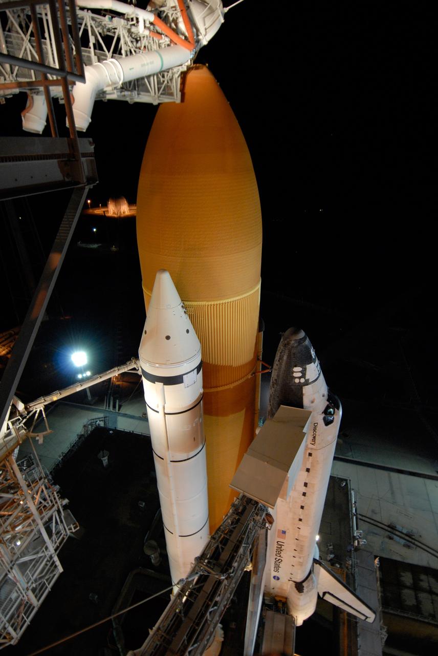
CAPE CANAVERAL, Fla. -- Bathed in lights surrounding Launch Pad 39A and its structures at NASA's Kennedy Space Center, space shuttle Discovery looks polished and ready for launch on the STS-124 mission after rollback of the rotating service structure. First motion was at 8:33 p.m. and rollback was complete at 9:07 p.m. The rotating structure provides protected access to the shuttle for changeout and servicing of payloads at the pad. It is supported by a rotating bridge that pivots on a vertical axis on the west side of the pad's flame trench. After the RSS is rolled back, the orbiter is ready for fuel cell activation and external tank cryogenic propellant loading operations. The pad is cleared to the perimeter gate for operations to fill the external tank with about 500,000 gallons of cryogenic propellants used by the shuttle’s main engines. This is done at the pad approximately eight hours before the scheduled launch. Along with the orange external tank and one of the two solid rocket boosters, the orbiter access arm is seen extended to the side of the shuttle. At the end is the White Room, which provides access into the shuttle. The STS-124 mission is the second of three flights launching components to complete the Japan Aerospace Exploration Agency's Kibo laboratory. The shuttle crew will install Kibo's large Japanese Pressurized Module and its remote manipulator system, or RMS. The 14-day flight includes three spacewalks. Launch is scheduled for 5:02 p.m. May 31. Photo credit: NASA/Troy Cryder