ISS017-E-013970 (22 Aug. 2008) --- Astronaut Greg Chamitoff, Expedition 17 flight engineer, conducts a function checkout for the Japanese Experiment Module's Remote Manipulator System in the Kibo laboratory on the International Space Station.
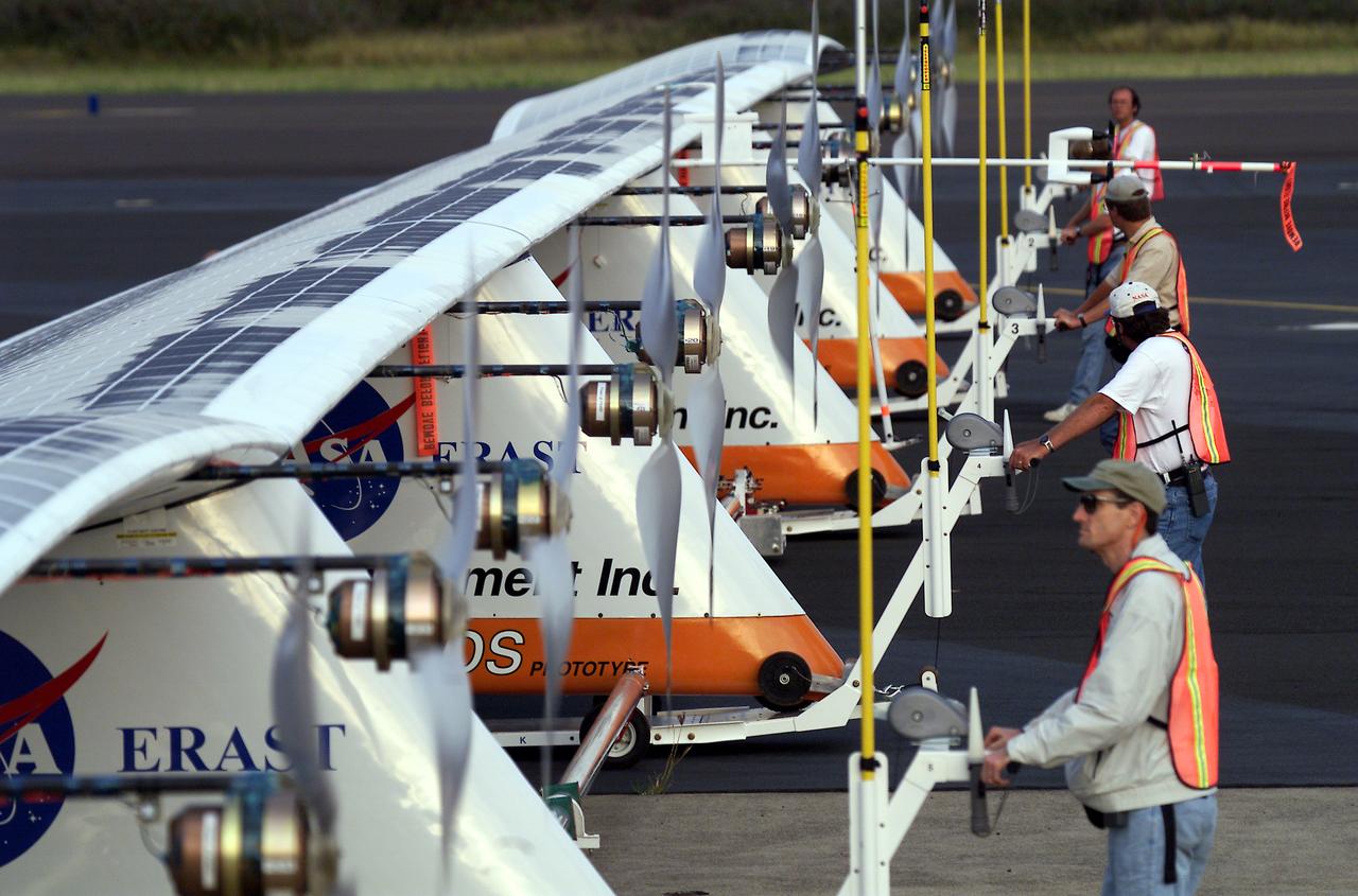
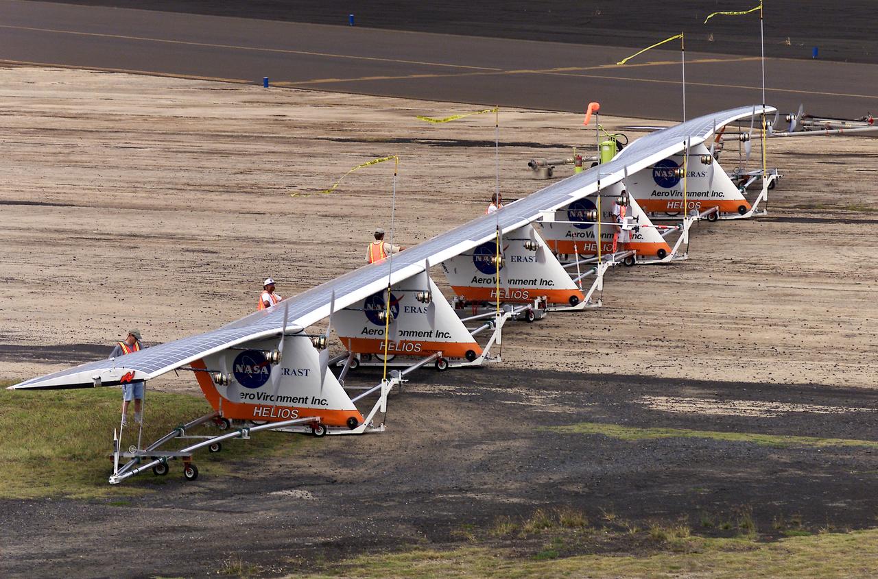
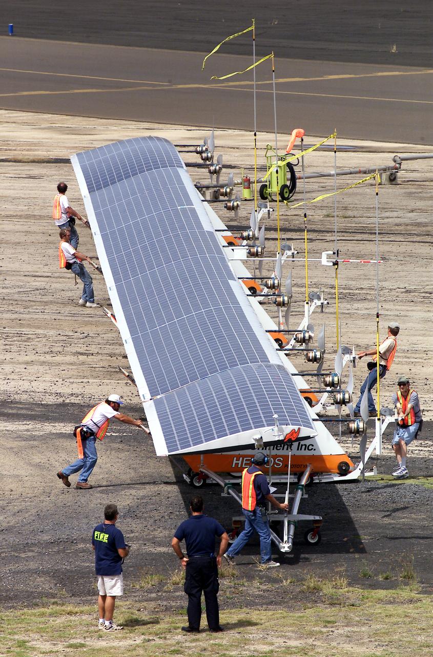
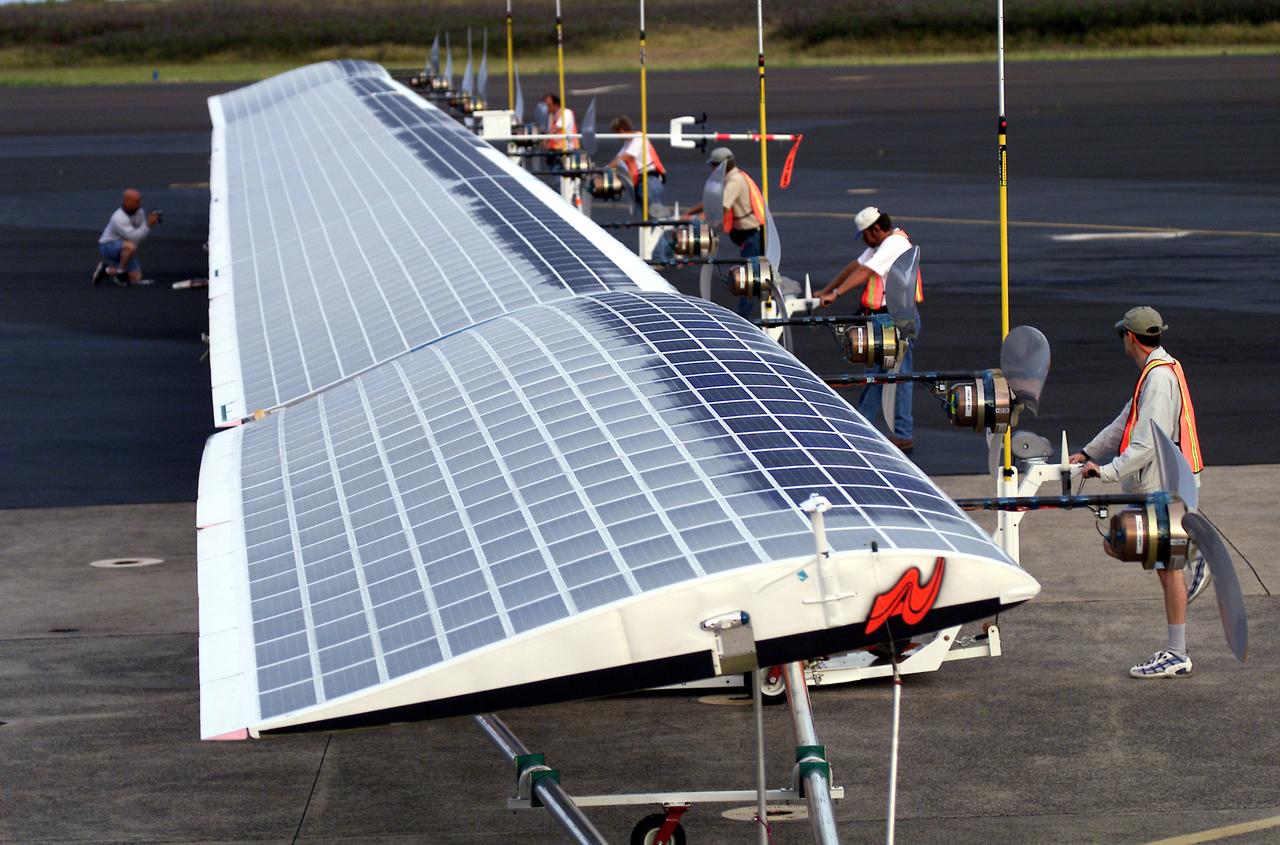
Ground crewmen maneuver AeroVironment's solar-powered Helios Prototype flying wing on its ground support dolly during functional checkouts prior to its first flights under solar power from the U.S. Navy's Pacific Missile Range Facility on Kaua'i, Hawaii.
Ground crewmen maneuver AeroVironment's solar-powered Helios Prototype flying wing on its ground support dolly during functional checkouts prior to its first flights under solar power from the U.S. Navy's Pacific Missile Range Facility on Kaua'i, Hawaii.
Ground crewmen maneuver AeroVironment's solar-powered Helios Prototype flying wing on its ground support dolly during functional checkouts prior to its first flights under solar power from the U.S. Navy's Pacific Missile Range Facility on Kaua'i, Hawaii.
Ground crewmen maneuver AeroVironment's solar-powered Helios Prototype flying wing on its ground support dolly during functional checkouts prior to its first flights under solar power from the U.S. Navy's Pacific Missile Range Facility on Kaua'i, Hawaii.
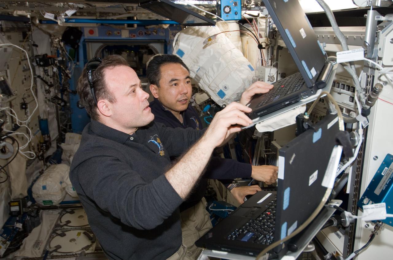
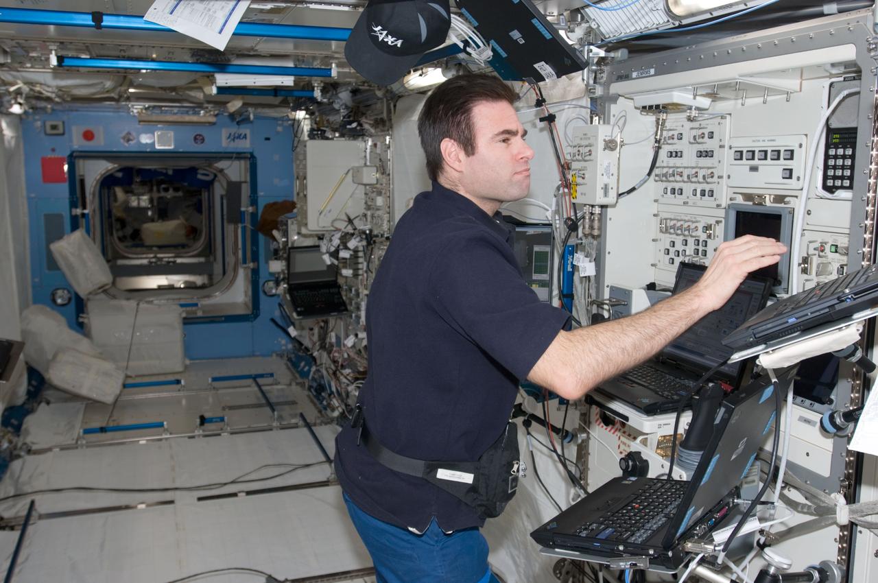
ISS028-E-020303 (2 Aug. 2011) --- NASA astronaut Ron Garan (foreground) and Japan Aerospace Exploration Agency astronaut Satoshi Furukawa, both Expedition 28 flight engineers, use computers in the International Space Station?s Kibo laboratory to monitor the Japanese Experiment Module Remote Manipulator System (JEMRMS) located on the exterior of the station.
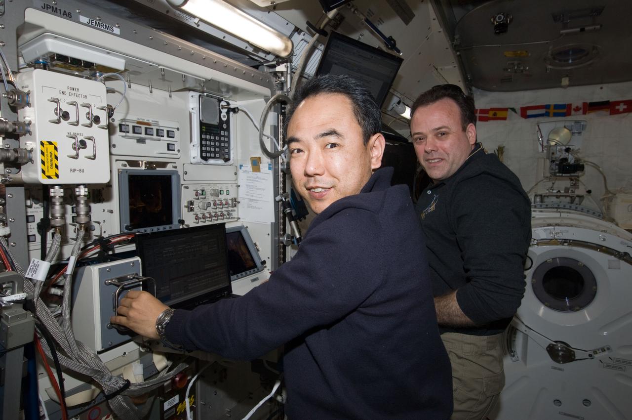
ISS028-E-020311 (2 Aug. 2011) --- From inside the International Space Station?s Kibo laboratory, Japan Aerospace Exploration Agency astronaut Satoshi Furukawa (foreground) and NASA astronaut Ron Garan, both Expedition 28 flight engineers, monitor the Japanese Experiment Module Remote Manipulator System (JEMRMS) located on the exterior of the station.
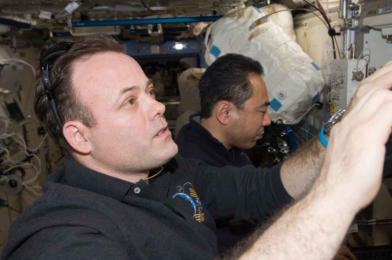
ISS028-E-020307 (2 Aug. 2011) --- NASA astronaut Ron Garan (foreground) and Japan Aerospace Exploration Agency astronaut Satoshi Furukawa, both Expedition 28 flight engineers, use computers in the International Space Station?s Kibo laboratory to monitor the Japanese Experiment Module Remote Manipulator System (JEMRMS) located on the exterior of the station.
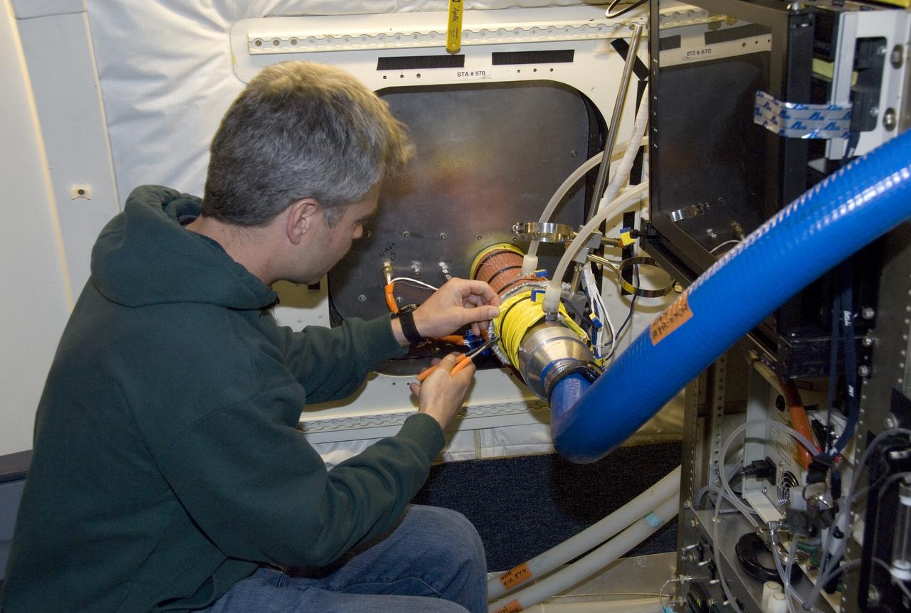
Climate researchers from the National Center for Atmospheric Research (NCAR) and several universities install and perform functional checkouts of a variety of sensitive atmospheric instruments on NASA's DC-8 airborne laboratory prior to beginning the ARCTAS mission.
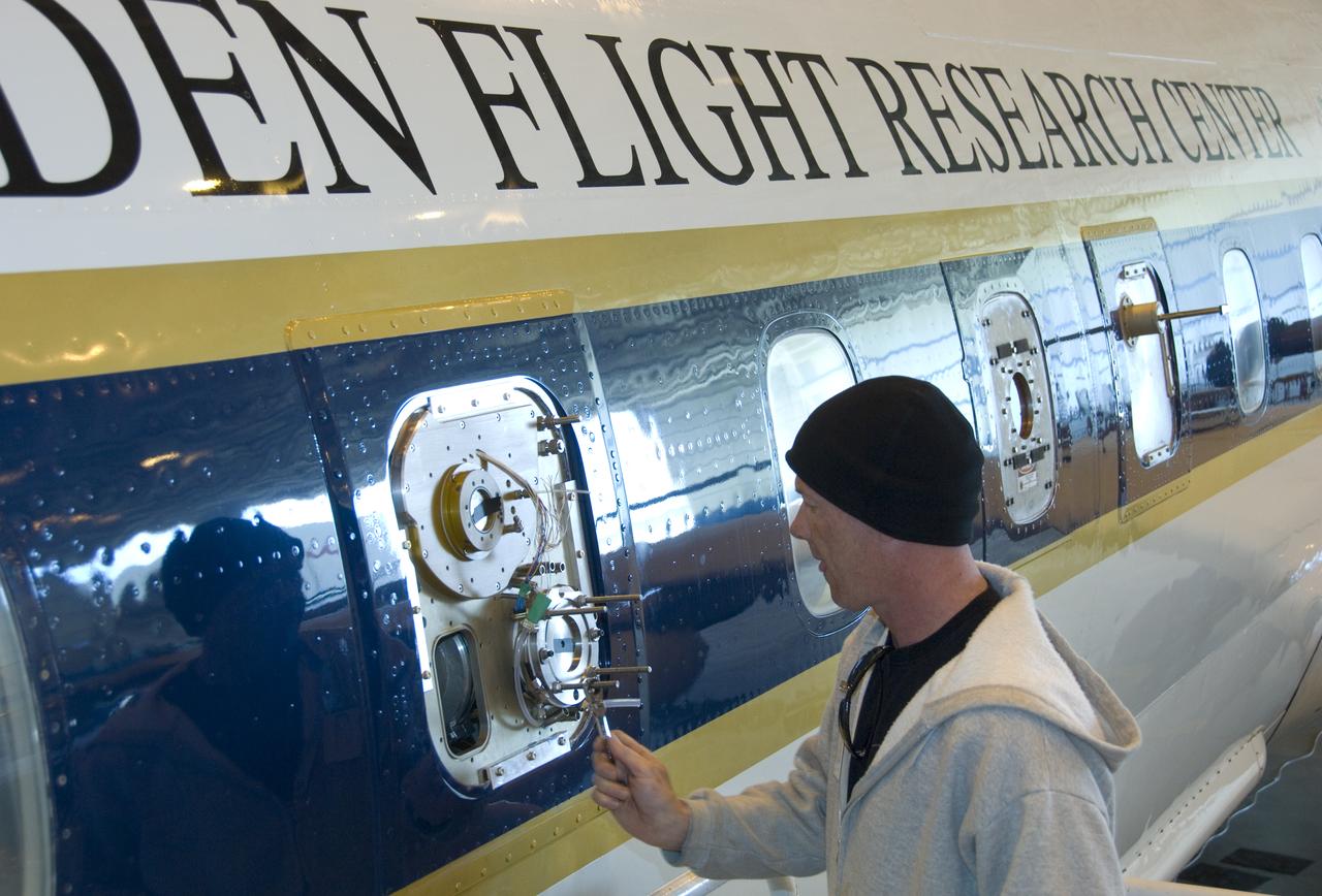
Climate researchers from the National Center for Atmospheric Research (NCAR) and several universities install and perform functional checkouts of a variety of sensitive atmospheric instruments on NASA's DC-8 airborne laboratory prior to beginning the ARCTAS mission.
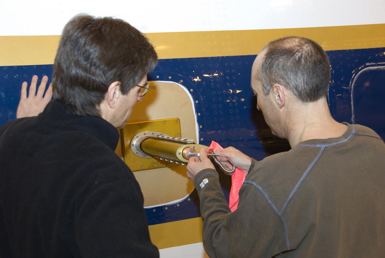
Climate researchers from the National Center for Atmospheric Research (NCAR) and several universities install and perform functional checkouts of a variety of sensitive atmospheric instruments on NASA's DC-8 airborne laboratory prior to beginning the ARCTAS mission.

Climate researchers from the National Center for Atmospheric Research (NCAR) and several universities install and perform functional checkouts of a variety of sensitive atmospheric instruments on NASA's DC-8 airborne laboratory prior to beginning the ARCTAS mission.

Climate researchers from the National Center for Atmospheric Research (NCAR) and several universities install and perform functional checkouts of a variety of sensitive atmospheric instruments on NASA's DC-8 airborne laboratory prior to beginning the ARCTAS mission.

Climate researchers from the National Center for Atmospheric Research (NCAR) and several universities install and perform functional checkouts of a variety of sensitive atmospheric instruments on NASA's DC-8 airborne laboratory prior to beginning the ARCTAS mission.
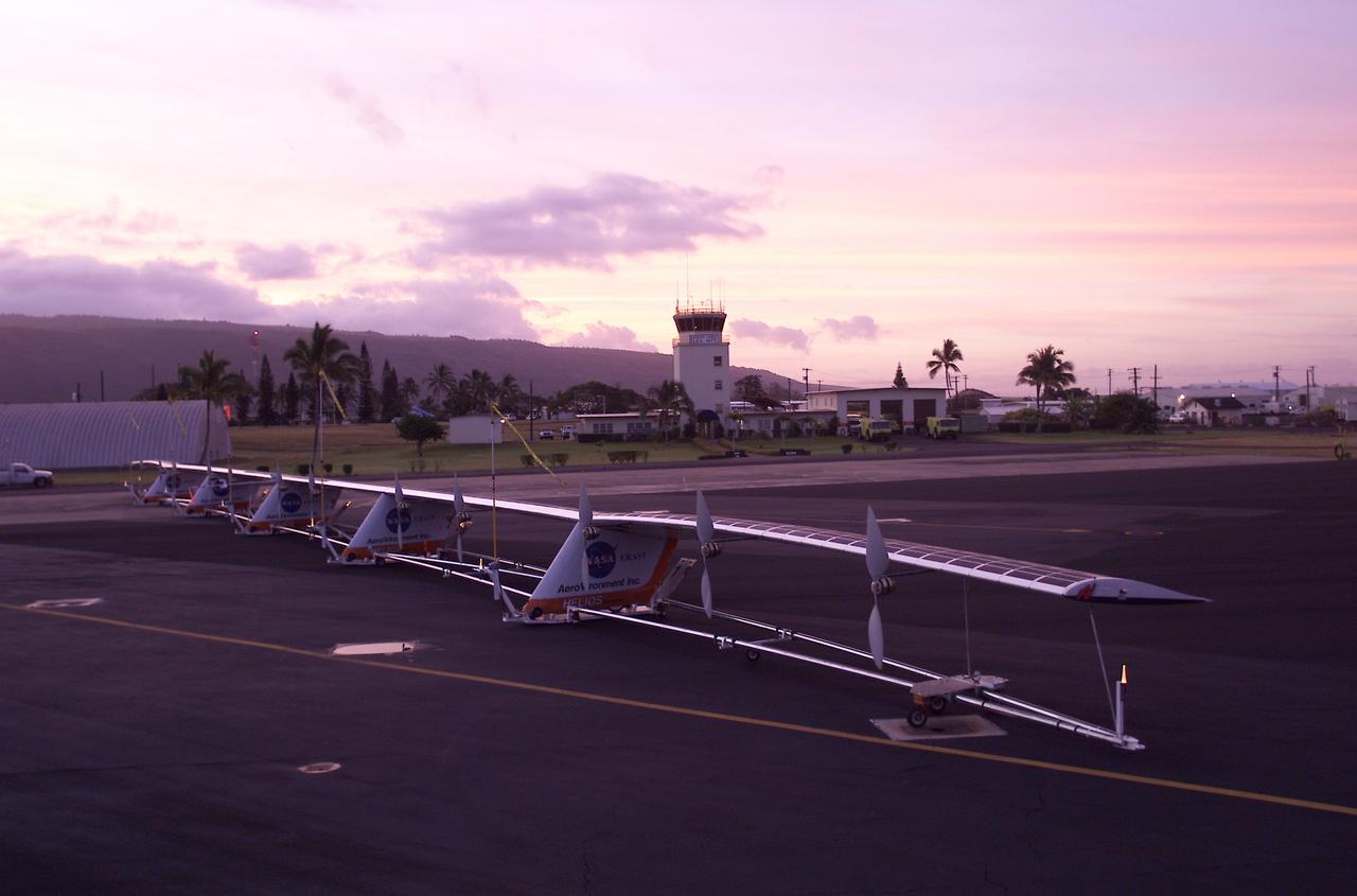
The 247-foot length of the Helios prototype wing is in evidence as the high-altitude, solar-powered flying wing rests on its ground dolly during pre-flight tests at the U.S. Navy's Pacific Missile Range Facility on Kaua'i, Hawaii.

ISS006-E-13995 (2 January 2003) --- Astronaut Donald R. Pettit, Expedition Six NASA ISS science officer, performs the Human Research Facility (HRF) Ultrasound functional checkout in the Destiny laboratory on the International Space Station (ISS).
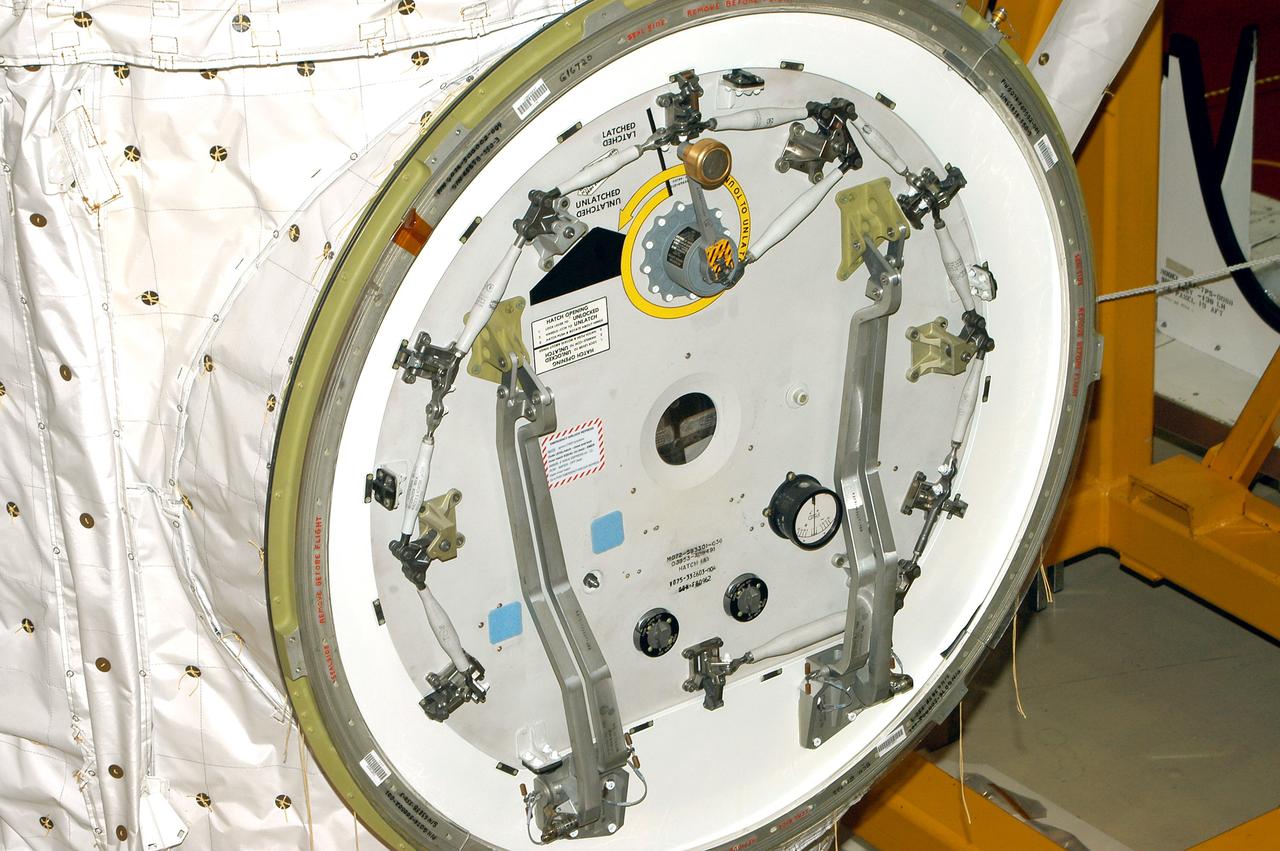
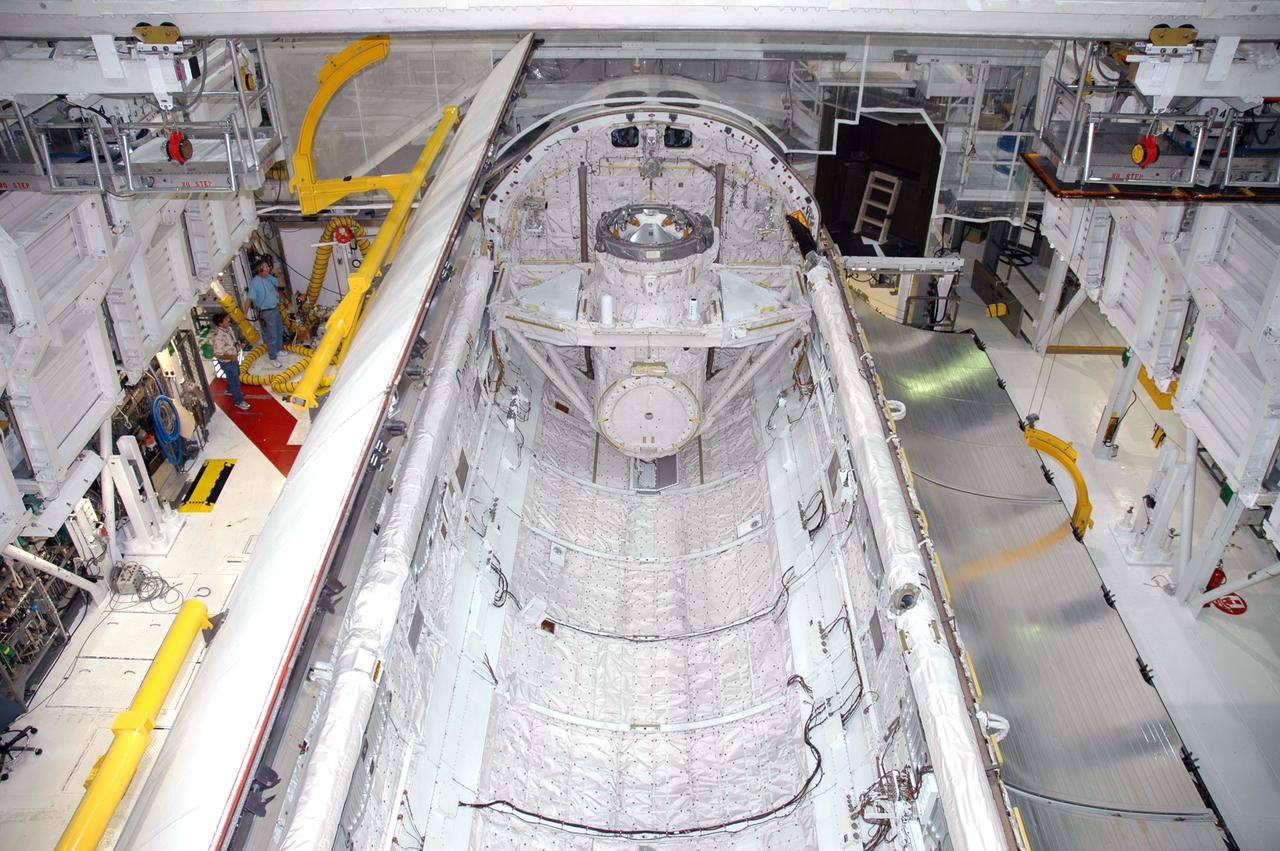
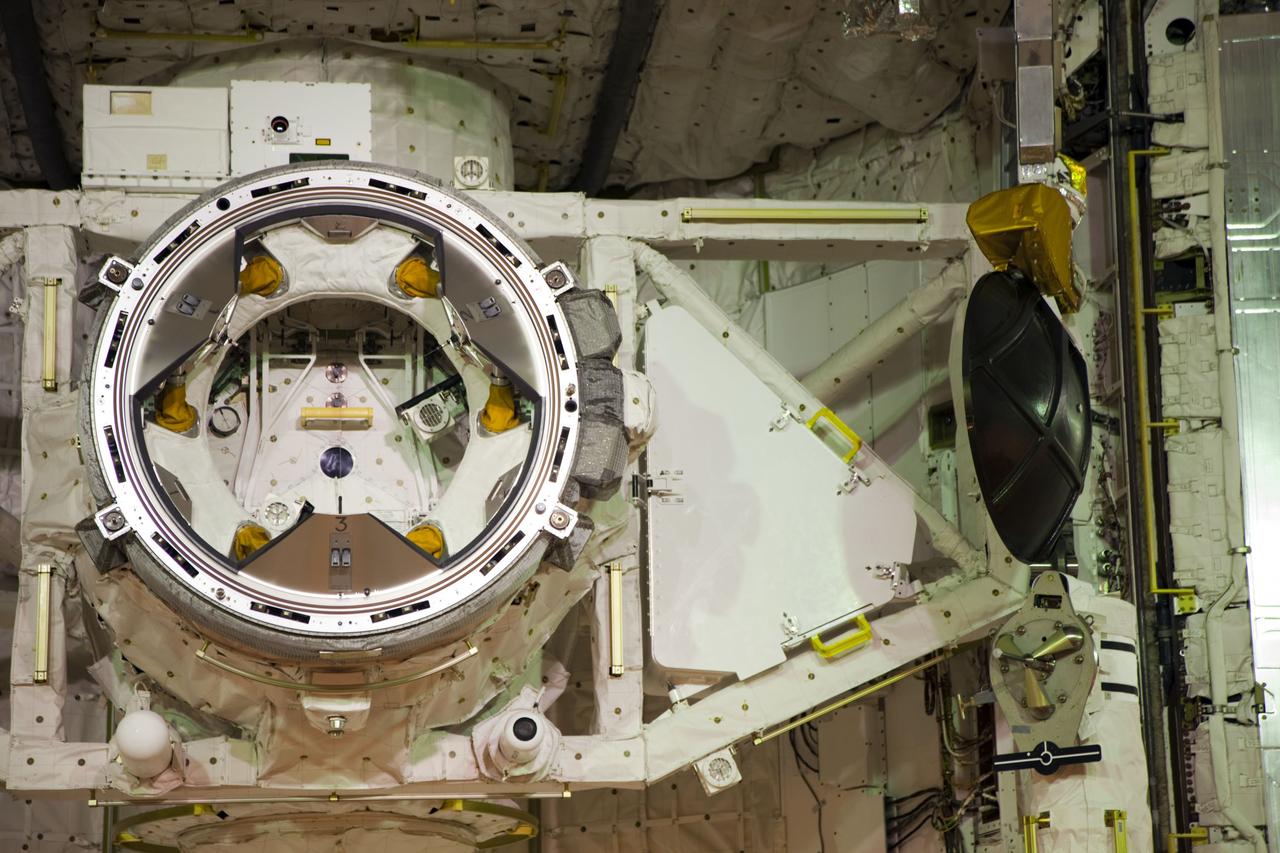
KENNEDY SPACE CENTER, FLA. - Seen in the photo is one end of the airlock that is installed in the payload bay of orbiter Discovery. The airlock is normally located inside the middeck of the spacecraft’s pressurized crew cabin. The airlock is sized to accommodate two fully suited flight crew members simultaneously. Support functions include airlock depressurization and repressurization, extravehicular activity equipment recharge, liquid-cooled garment water cooling, EVA equipment checkout, donning and communications. The outer hatch isolates the airlock from the unpressurized payload bay when closed and permits the EVA crew members to exit from the airlock to the payload bay when open.

KENNEDY SPACE CENTER, FLA. - In the Orbiter Processing Facility, a worker checks out part of the equipment in the airlock, at one end of Discovery’s payload bay. The airlock is sized to accommodate two fully suited flight crew members simultaneously. Support functions include airlock depressurization and repressurization, extravehicular activity equipment recharge, liquid-cooled garment water cooling, EVA equipment checkout, donning and communications. The outer hatch isolates the airlock from the unpressurized payload bay when closed and permits the EVA crew members to exit from the airlock to the payload bay when open.
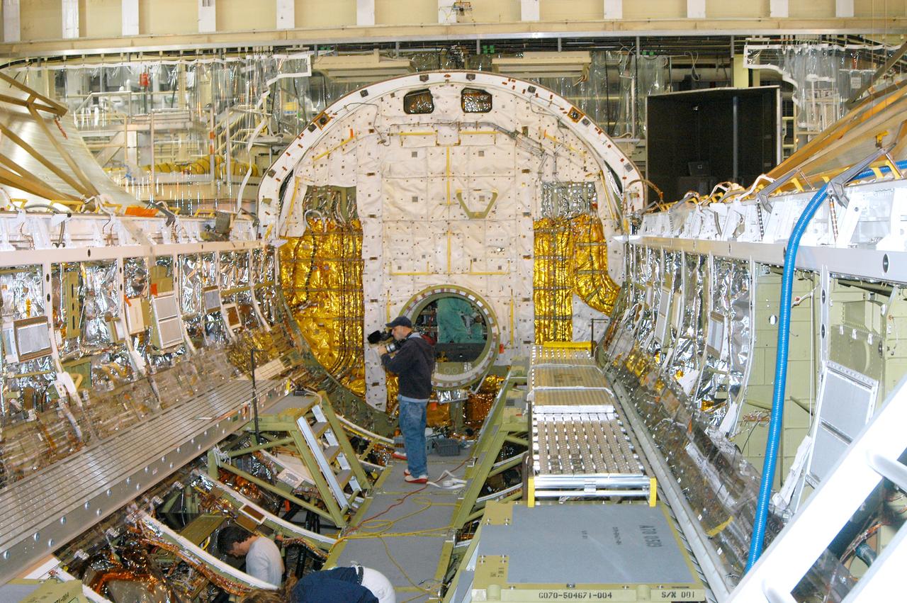
KENNEDY SPACE CENTER, FLA. - In the Orbiter Processing Facility, a cameraman films part of Discovery’s payload bay for a special feature on the KSC Web. In the background is the open hatch of the airlock, located inside the middeck of the spacecraft’s pressurized crew cabin. The airlock is sized to accommodate two fully suited flight crew members simultaneously. Support functions include airlock depressurization and repressurization, extravehicular activity equipment recharge, liquid-cooled garment water cooling, EVA equipment checkout, donning and communications. The outer hatch isolates the airlock from the unpressurized payload bay when closed and permits the EVA crew members to exit from the airlock to the payload bay when open.
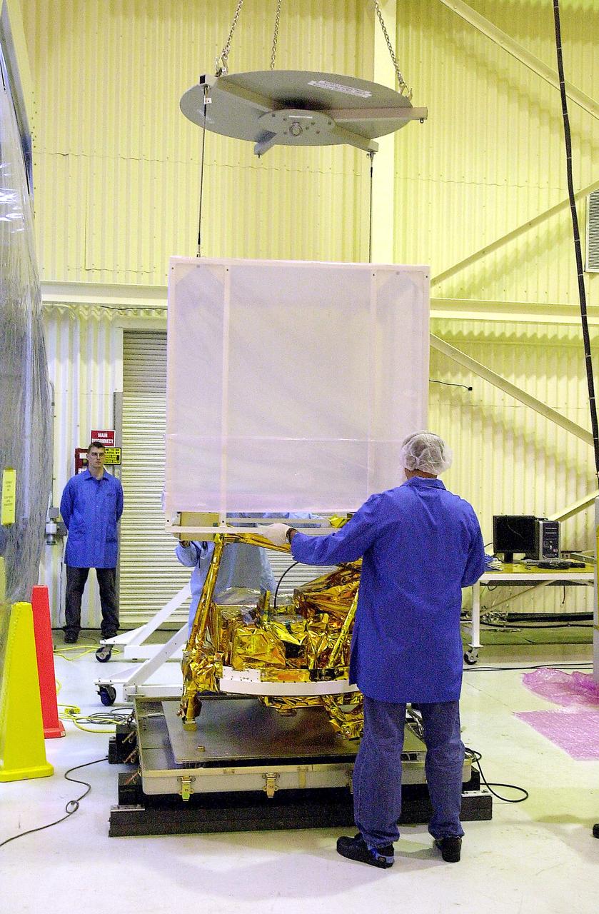
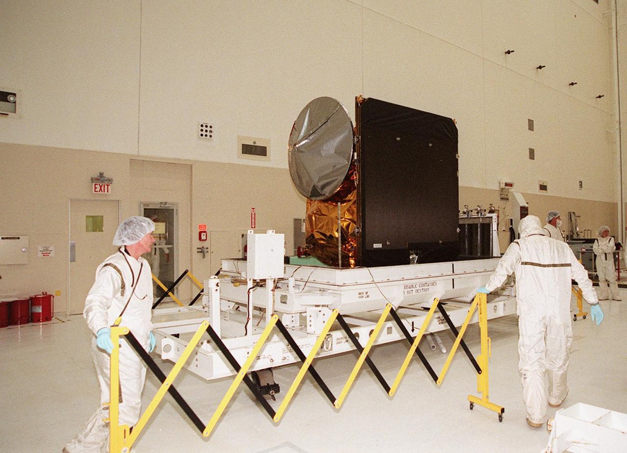
VANDENBERG AIR FORCE BASE, CALIF.- The cover is being lifted off SciSat-1 spacecraft at Vandenberg Air Force Base, Calif. Sci-Sat, which will undergo instrument checkout and spacecraft functional testing, weighs approximately 330 pounds and after launch will be placed in a 400-mile-high polar orbit to investigate processes that control the distribution of ozone in the upper atmosphere. The data from the satellite will provide Canadian and international scientists with improved measurements relating to global ozone processes and help policymakers assess existing environmental policy and develop protective measures for improving the health of our atmosphere, preventing further ozone depletion. The mission is designed to last two years.
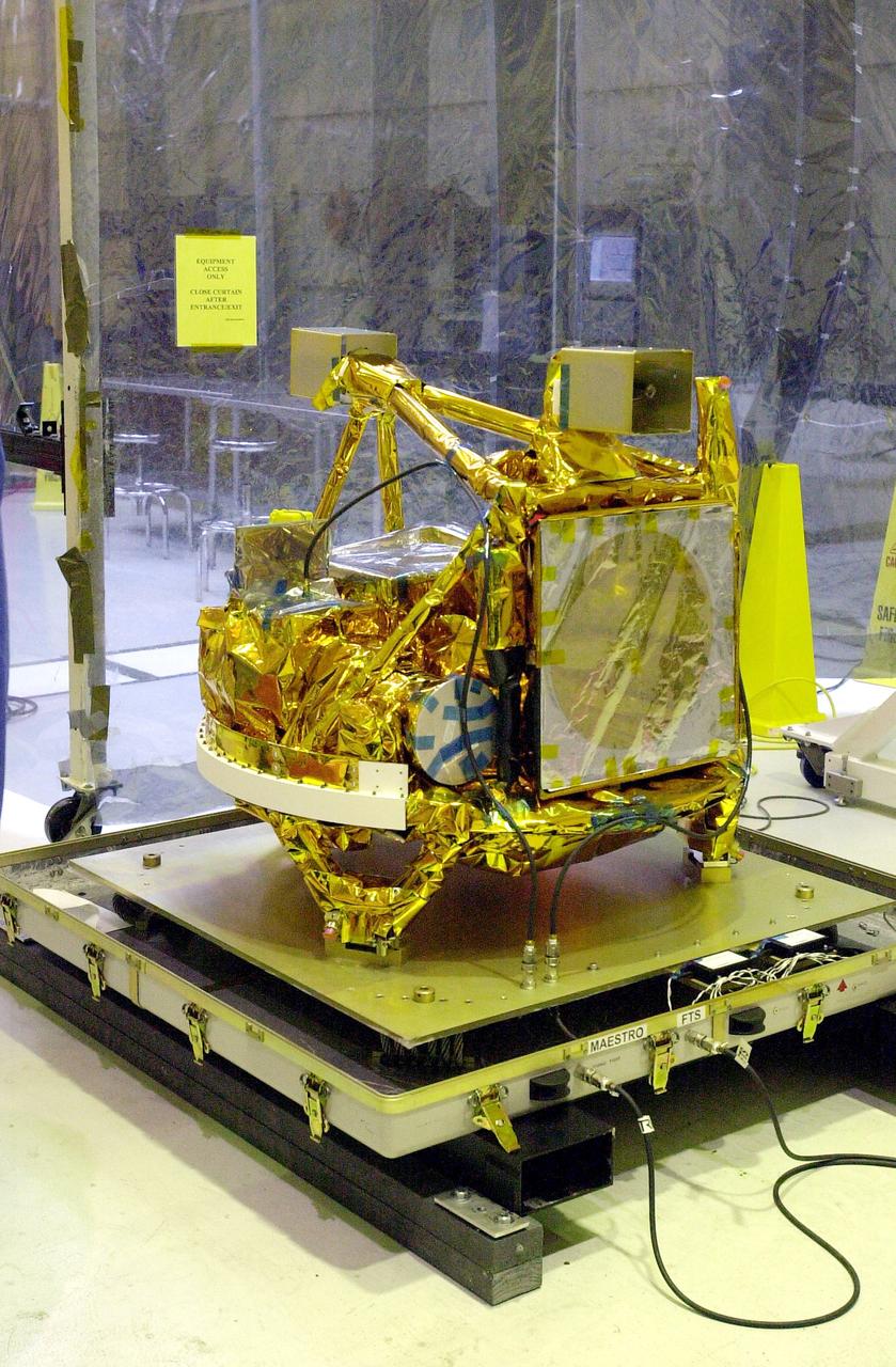
VANDENBERG AIR FORCE BASE, CALIF. - The SciSat-1 spacecraft is revealed at Vandenberg Air Force Base, Calif. Sci-Sat, which will undergo instrument checkout and spacecraft functional testing, weighs approximately 330 pounds and after launch will be placed in a 400-mile-high polar orbit to investigate processes that control the distribution of ozone in the upper atmosphere. The data from the satellite will provide Canadian and international scientists with improved measurements relating to global ozone processes and help policymakers assess existing environmental policy and develop protective measures for improving the health of our atmosphere, preventing further ozone depletion. The mission is designed to last two years.
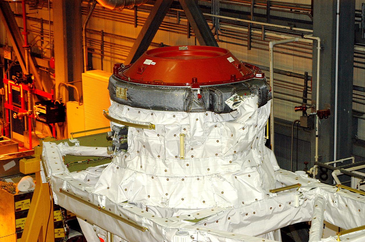
KENNEDY SPACE CENTER, FLA. - Seen in the photo is one end of the airlock that is installed in the payload bay of orbiter Discovery. The airlock is normally located inside the middeck of the spacecraft’s pressurized crew cabin. The airlock is sized to accommodate two fully suited flight crew members simultaneously. Support functions include airlock depressurization and repressurization, extravehicular activity equipment recharge, liquid-cooled garment water cooling, EVA equipment checkout, donning and communications. The outer hatch isolates the airlock from the unpressurized payload bay when closed and permits the EVA crew members to exit from the airlock to the payload bay when open.
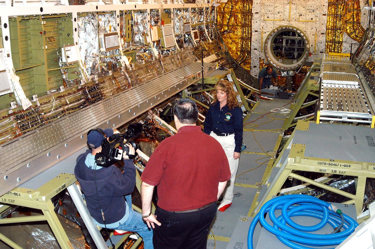
KENNEDY SPACE CENTER, FLA. - Standing inside Discovery’s payload bay, Carol Scott (right), lead orbiter engineer, talks about her job as part of a special feature for the KSC Web. With his back to the camera is Bill Kallus, Media manager in the KSC Web Studio. Behind Scott can be seen the open hatch of the airlock, which provides support functions such as airlock depressurization and repressurization, extravehicular activity equipment recharge, liquid-cooled garment water cooling, EVA equipment checkout, donning and communications. The outer hatch isolates the airlock from the unpressurized payload bay when closed and permits the EVA crew members to exit from the airlock to the payload bay when open.
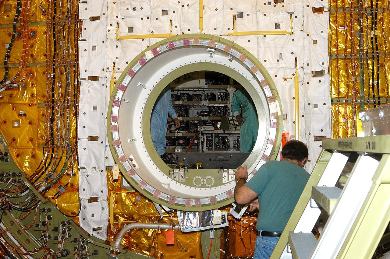
KENNEDY SPACE CENTER, FLA. - A worker in the Orbiter Processing Facility checks the open hatch of the airlock in Discovery’s payload bay. The airlock is normally located inside the middeck of the spacecraft’s pressurized crew cabin. The airlock is sized to accommodate two fully suited flight crew members simultaneously. Support functions include airlock depressurization and repressurization, extravehicular activity equipment recharge, liquid-cooled garment water cooling, EVA equipment checkout, donning and communications. The outer hatch isolates the airlock from the unpressurized payload bay when closed and permits the EVA crew members to exit from the airlock to the payload bay when open.
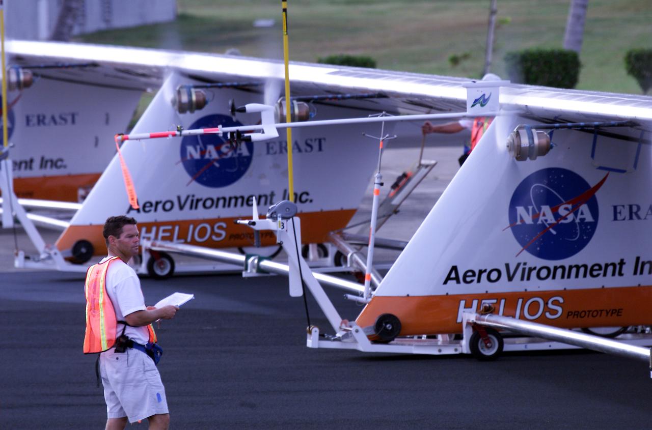
Helios Prototype crew chief Marshall MacCready of AeroVironment, Inc., carefully monitors motor runs during ground checkout of the solar-powered flying wing prior to its first flight from the U.S. Navy's Pacific Missile Range Facility on Kaua'i, Hawaii.
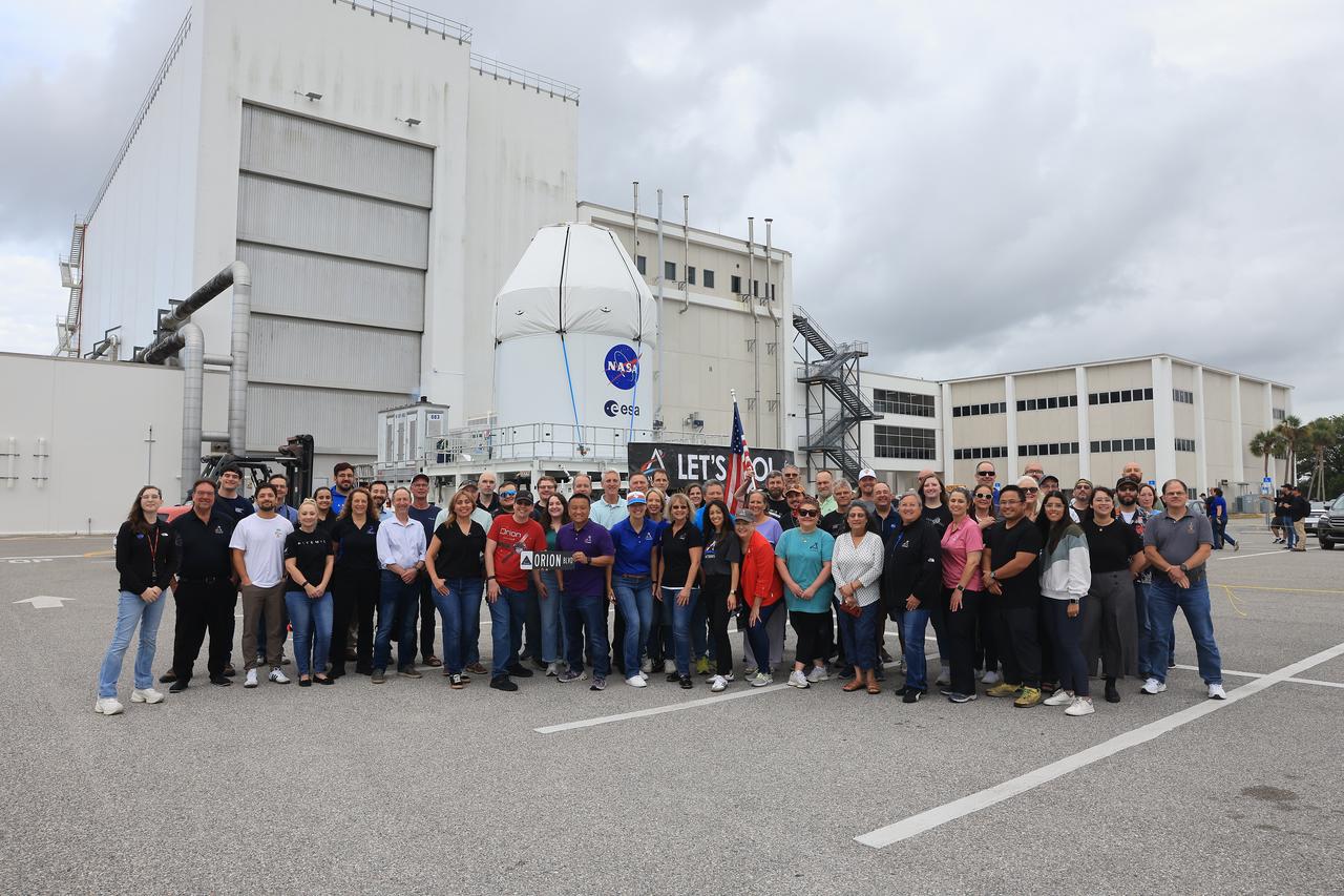
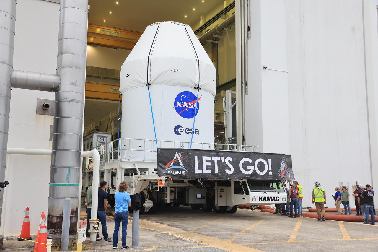
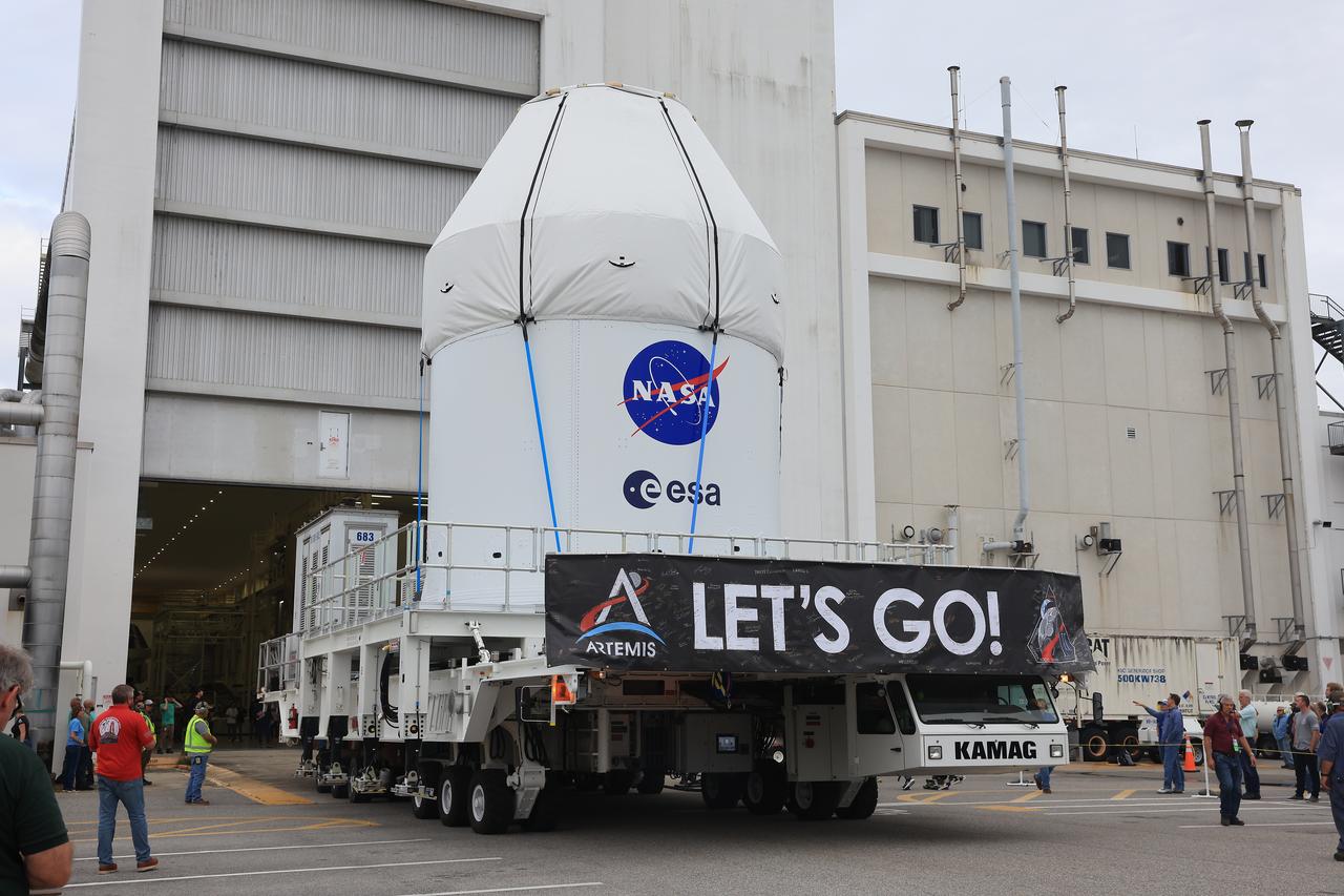
NASA’s KAMAG transporter carries the agency’s Artemis II Orion spacecraft from the Neil A. Armstrong Operations and Checkout Building to the Multi-Payload Processing Facility at Kennedy Space Center in Florida on Saturday, May 3, 2025. The Orion spacecraft will undergo fueling and processing operations at the Multi-Function Facility. The Artemis II test flight is the first crewed flight under NASA’s Artemis campaign and is another step toward missions on the lunar surface and helping the agency prepare for future human missions to Mars.
The solar-electric Helios Prototype flying wing is shown near the Hawaiian island of Niihau during its first test flight on solar power from the U.S. Navy's Pacific Missile Range Facility on Kauai, Hawaii, July 14, 2001. The 18-hour flight was a functional checkout of the aircraft's systems and performance in preparation for an attempt to reach sustained flight at 100,000 feet altitude later this summer.
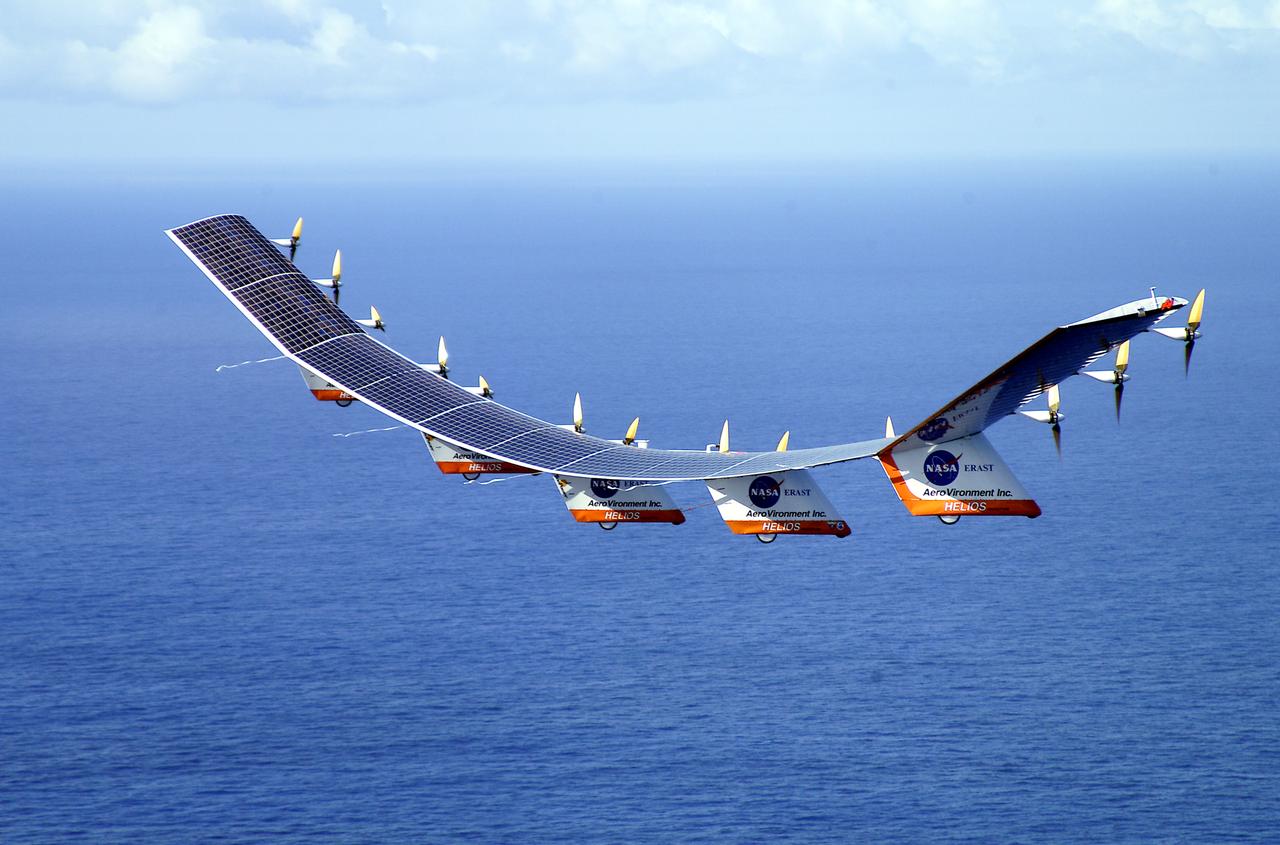
The solar-electric Helios Prototype flying wing is shown over the Pacific Ocean during its first test flight on solar power from the U.S. Navy's Pacific Missile Range Facility on Kauai, Hawaii, July 14, 2001. The 18-hour flight was a functional checkout of the aircraft's systems and performance in preparation for an attempt to reach sustained flight at 100,000 feet altitude later this summer.
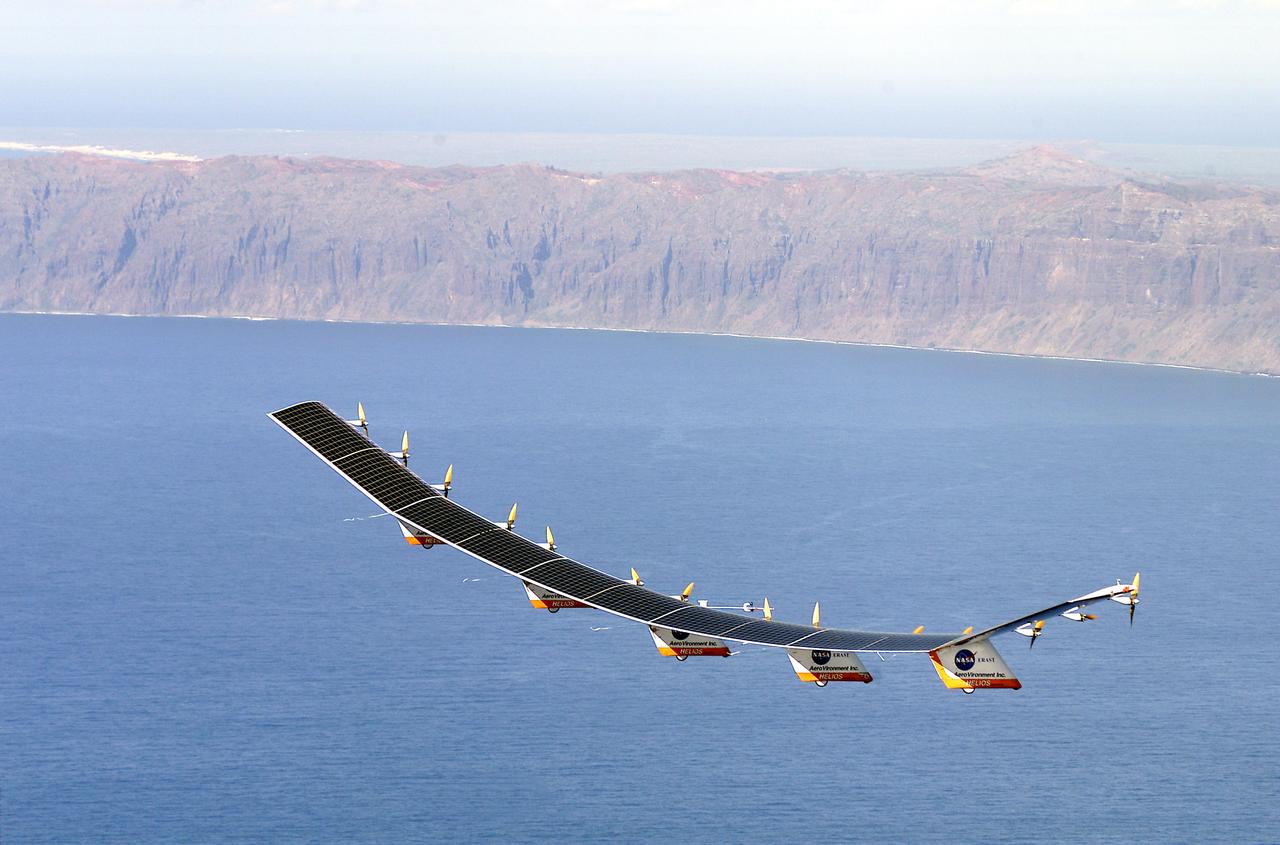
The solar-electric Helios Prototype flying wing is shown near the Hawaiian island of Niihau during its first test flight on solar power from the U.S. Navy's Pacific Missile Range Facility on Kauai, Hawaii, July 14, 2001. The 18-hour flight was a functional checkout of the aircraft's systems and performance in preparation for an attempt to reach sustained flight at 100,000 feet altitude later this summer.
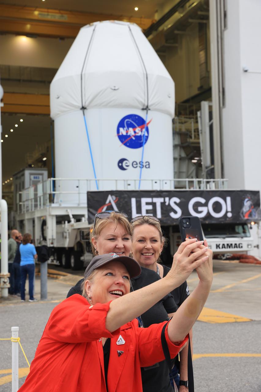
NASA’s KAMAG transporter carries the agency’s Artemis II Orion spacecraft from the Neil A. Armstrong Operations and Checkout Building to the Multi-Payload Processing Facility at Kennedy Space Center in Florida on Saturday, May 3, 2025. The Orion spacecraft will undergo fueling and processing operations at the Multi-Function Facility. The Artemis II test flight is the first crewed flight under NASA’s Artemis campaign and is another step toward missions on the lunar surface and helping the agency prepare for future human missions to Mars.
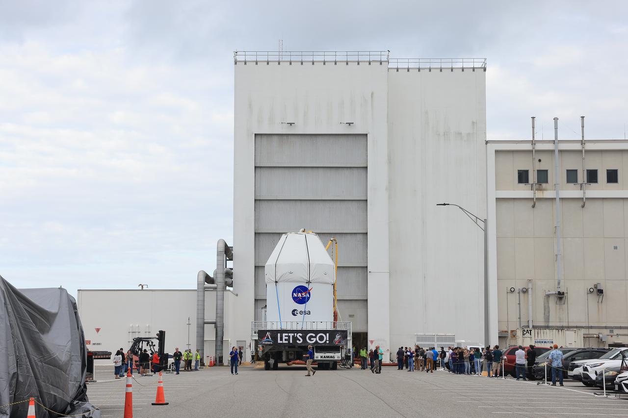
NASA’s KAMAG transporter carries the agency’s Artemis II Orion spacecraft from the Neil A. Armstrong Operations and Checkout Building to the Multi-Payload Processing Facility at Kennedy Space Center in Florida on Saturday, May 3, 2025. The Orion spacecraft will undergo fueling and processing operations at the Multi-Function Facility. The Artemis II test flight is the first crewed flight under NASA’s Artemis campaign and is another step toward missions on the lunar surface and helping the agency prepare for future human missions to Mars.
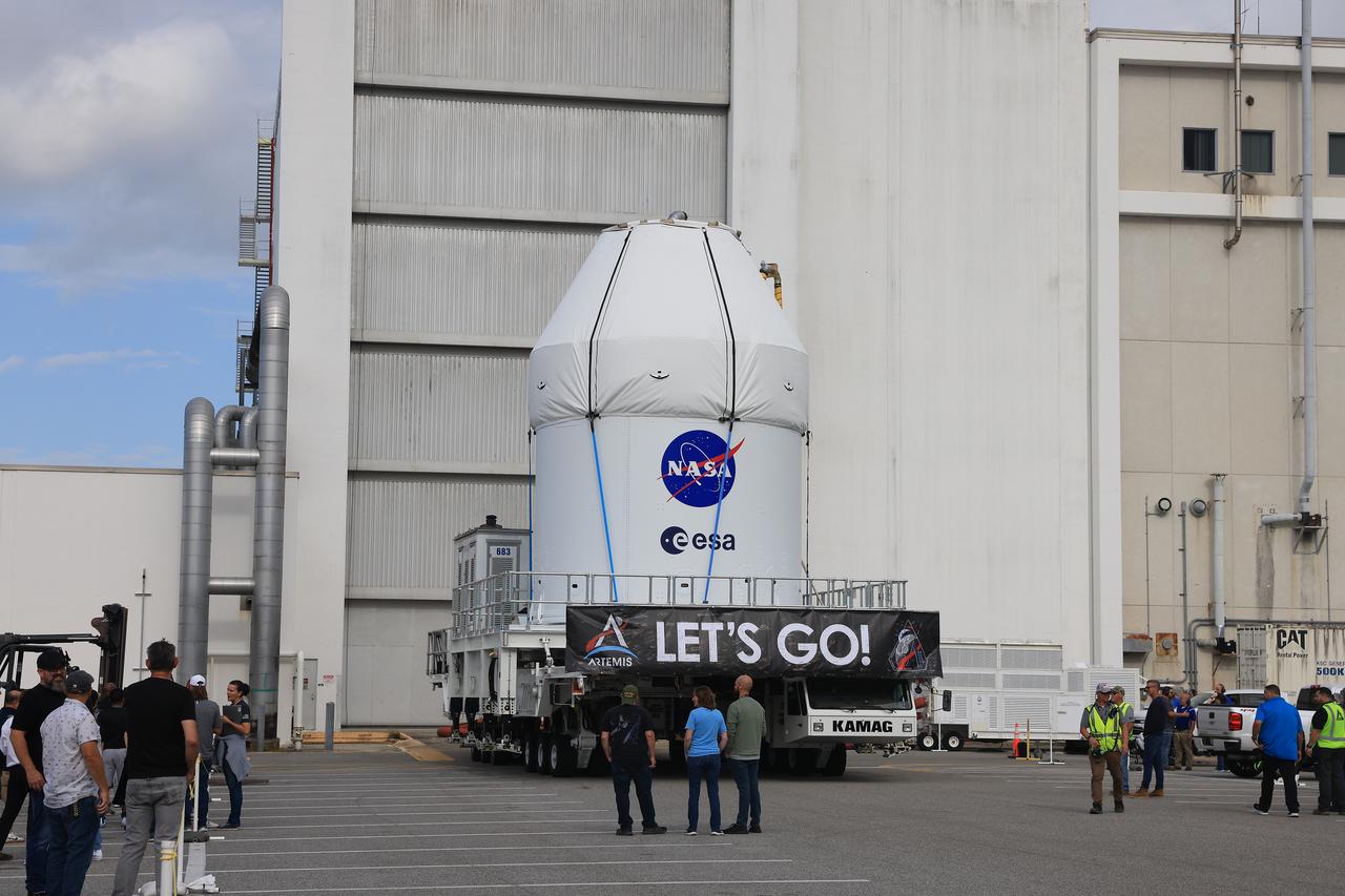
NASA’s KAMAG transporter carries the agency’s Artemis II Orion spacecraft from the Neil A. Armstrong Operations and Checkout Building to the Multi-Payload Processing Facility at Kennedy Space Center in Florida on Saturday, May 3, 2025. The Orion spacecraft will undergo fueling and processing operations at the Multi-Function Facility. The Artemis II test flight is the first crewed flight under NASA’s Artemis campaign and is another step toward missions on the lunar surface and helping the agency prepare for future human missions to Mars.
NASA’s KAMAG transporter carries the agency’s Artemis II Orion spacecraft from the Neil A. Armstrong Operations and Checkout Building to the Multi-Payload Processing Facility at Kennedy Space Center in Florida on Saturday, May 3, 2025. The Orion spacecraft will undergo fueling and processing operations at the Multi-Function Facility. The Artemis II test flight is the first crewed flight under NASA’s Artemis campaign and is another step toward missions on the lunar surface and helping the agency prepare for future human missions to Mars.
NASA’s KAMAG transporter carries the agency’s Artemis II Orion spacecraft from the Neil A. Armstrong Operations and Checkout Building to the Multi-Payload Processing Facility at Kennedy Space Center in Florida on Saturday, May 3, 2025. The Orion spacecraft will undergo fueling and processing operations at the Multi-Function Facility. The Artemis II test flight is the first crewed flight under NASA’s Artemis campaign and is another step toward missions on the lunar surface and helping the agency prepare for future human missions to Mars.
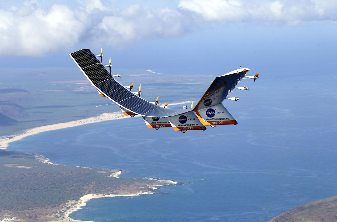
The solar-electric Helios Prototype flying wing is shown near the Hawaiian islands of Niihau and Lehua during its first test flight on solar power from the U.S. Navy's Pacific Missile Range Facility on Kauai, Hawaii, July 14, 2001. The 18-hour flight was a functional checkout of the aircraft's systems and performance in preparation for an attempt to reach sustained flight at 100,000 feet altitude later this summer.
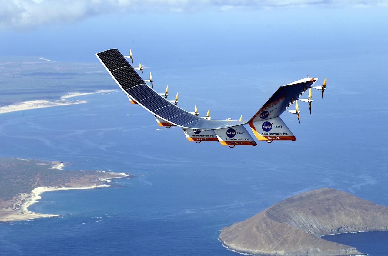
The solar-electric Helios Prototype flying wing is shown near the Hawaiian islands of Niihau and Lehua during its first test flight on solar power from the U.S. Navy's Pacific Missile Range Facility on Kauai, Hawaii, July 14, 2001. The 18-hour flight was a functional checkout of the aircraft's systems and performance in preparation for an attempt to reach sustained flight at 100,000 feet altitude later this summer.
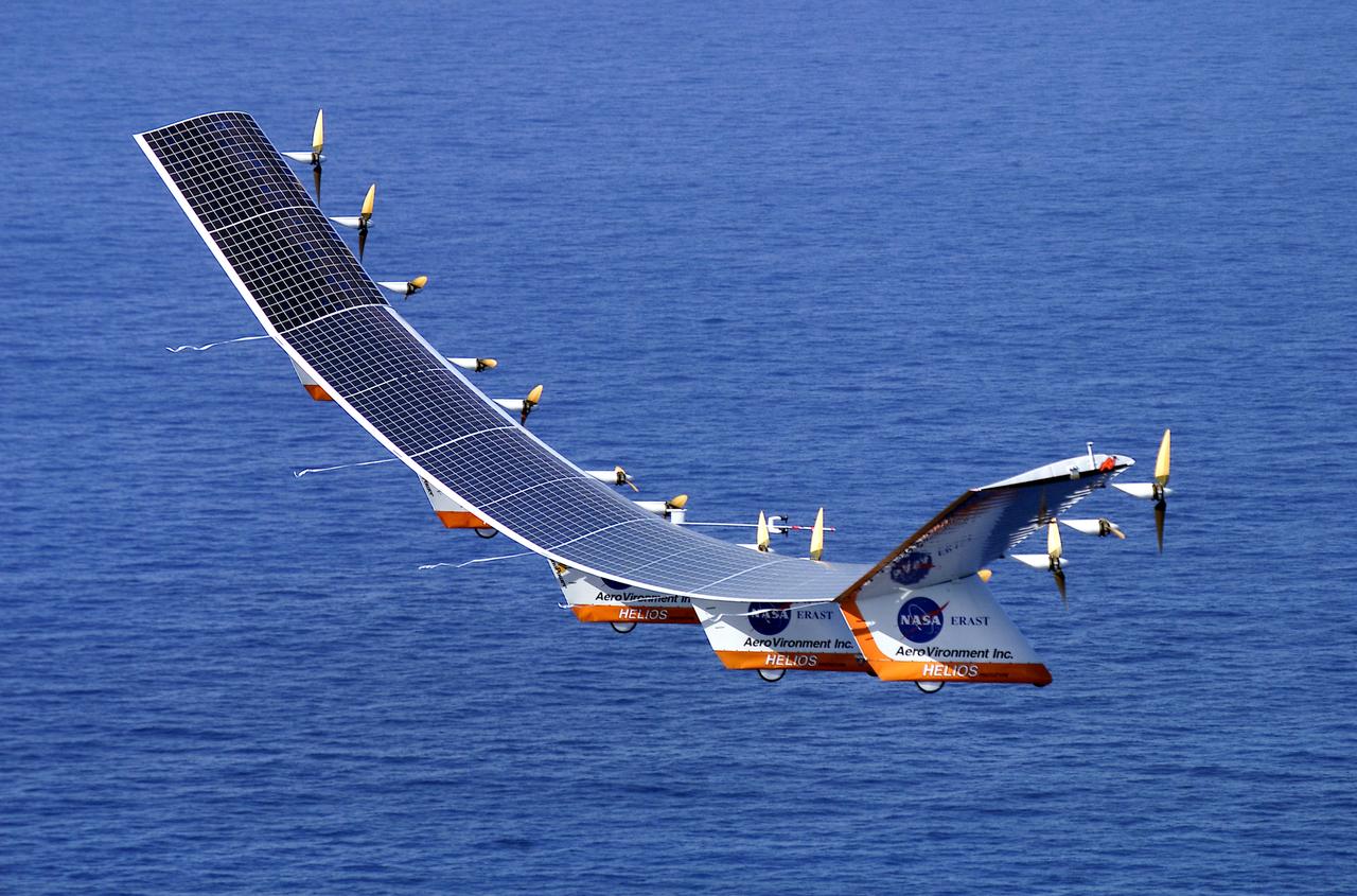
The solar-electric Helios Prototype flying wing is shown over the Pacific Ocean during its first test flight on solar power from the U.S. Navy's Pacific Missile Range Facility on Kauai, Hawaii, July 14, 2001. The 18-hour flight was a functional checkout of the aircraft's systems and performance in preparation for an attempt to reach sustained flight at 100,000 feet altitude later this summer.
NASA’s KAMAG transporter carries the agency’s Artemis II Orion spacecraft from the Neil A. Armstrong Operations and Checkout Building to the Multi-Payload Processing Facility at Kennedy Space Center in Florida on Saturday, May 3, 2025. The Orion spacecraft will undergo fueling and processing operations at the Multi-Function Facility. The Artemis II test flight is the first crewed flight under NASA’s Artemis campaign and is another step toward missions on the lunar surface and helping the agency prepare for future human missions to Mars.

NASA’s KAMAG transporter carries the agency’s Artemis II Orion spacecraft from the Neil A. Armstrong Operations and Checkout Building to the Multi-Payload Processing Facility at Kennedy Space Center in Florida on Saturday, May 3, 2025. The Orion spacecraft will undergo fueling and processing operations at the Multi-Function Facility. The Artemis II test flight is the first crewed flight under NASA’s Artemis campaign and is another step toward missions on the lunar surface and helping the agency prepare for future human missions to Mars.
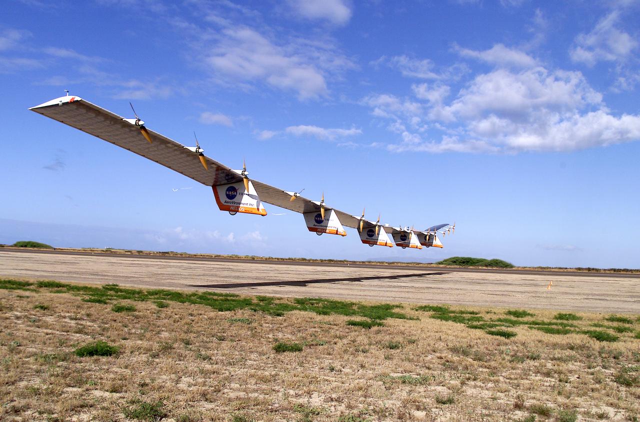
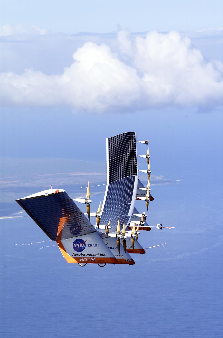
The solar-electric Helios Prototype flying wing is shown moments after takeoff, beginning its first test flight on solar power from the U.S. Navy's Pacific Missile Range Facility on Kauai, Hawaii, July 14, 2001. The 18-hour flight was a functional checkout of the aircraft's systems and performance in preparation for an attempt to reach sustained flight at 100,000 feet altitude later this summer.
VANDENBERG AIR FORCE BASE, CALIF. - Outside the clean room at Vandenberg Air Force Base, Calif., the SciSat-1 spacecraft (background) has been removed from the shipping container mounting base (lower left) and placed on the handling fixture. Sci-Sat, which will undergo instrument checkout and spacecraft functional testing, weighs approximately 330 pounds and after launch will be placed in a 400-mile-high polar orbit to investigate processes that control the distribution of ozone in the upper atmosphere. The data from the satellite will provide Canadian and international scientists with improved measurements relating to global ozone processes and help policymakers assess existing environmental policy and develop protective measures for improving the health of our atmosphere, preventing further ozone depletion. The mission is designed to last two years.

Consoles in the Radiological Control Center at NASA's Kennedy Space Center are seen during ceremonies to name the facility in honor of Randy Scott. A professional health physicist of more than 40 years, Scott served as the Florida spaceport's Radiation Protection Officer for 14 years until his death June 17, 2016. Located in the Neil Armstrong Operations and Checkout building, the Randall E. Scott Radiological Control Center is staffed by technical and radiological experts from NASA, the U.S. Department of Energy, the U.S. Air Force 45th Space Wing and the state of Florida. The group performs data collection and assessment functions supporting launch site and field data collection activities.
KENNEDY SPACE CENTER, FLA. -- Discovery’s airlock is lowered into the orbiter’s payload bay for installation. The airlock is sized to accommodate two fully suited flight crew members simultaneously. Support functions include airlock depressurization and repressurization, extravehicular activity equipment recharge, liquid-cooled garment water cooling, EVA equipment checkout, and communications. Discovery is designated as the Return to Flight vehicle for mission STS-114, no earlier than March 2005. STS-114 mission is Logistics Flight 1, which is scheduled to deliver supplies and equipment plus the external stowage platform to the International Space Station.

KENNEDY SPACE CENTER, FLA. -- Technicians in the Orbiter Processing Facility help guide Discovery’s airlock into the orbiter’s payload bay for installation. The airlock is sized to accommodate two fully suited flight crew members simultaneously. Support functions include airlock depressurization and repressurization, extravehicular activity equipment recharge, liquid-cooled garment water cooling, EVA equipment checkout, and communications. Discovery is designated as the Return to Flight vehicle for mission STS-114, no earlier than March 2005. STS-114 mission is Logistics Flight 1, which is scheduled to deliver supplies and equipment plus the external stowage platform to the International Space Station.
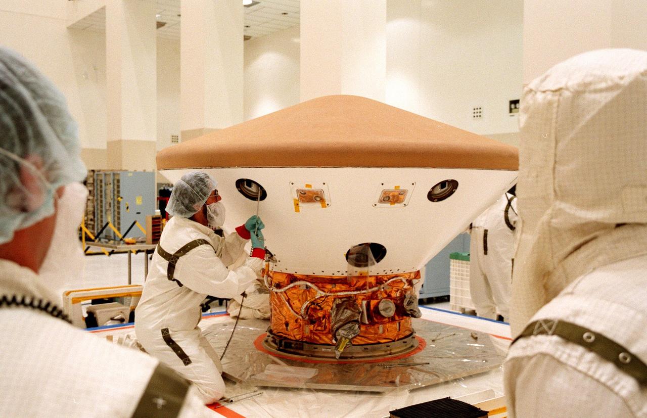
KENNEDY SPACE CENTER, FLA. -- In the Spacecraft Assembly and Encapsulation Facility-2 (SAEF-2), a technician begins testing on the Mars Polar Lander. The checkout includes a functional test of the science instruments and the basic spacecraft subsystems. The Mars Polar Lander is targeted for launch from Cape Canaveral Air Station aboard a Delta II rocket on Jan. 3, 1999. The solar-powered spacecraft is designed to touch down on the Martian surface near the northern-most boundary of the south pole in order to study the water cycle there. The lander also will help scientists learn more about climate change and current resources on Mars, studying such things as frost, dust, water vapor and condensates in the Martian atmosphere

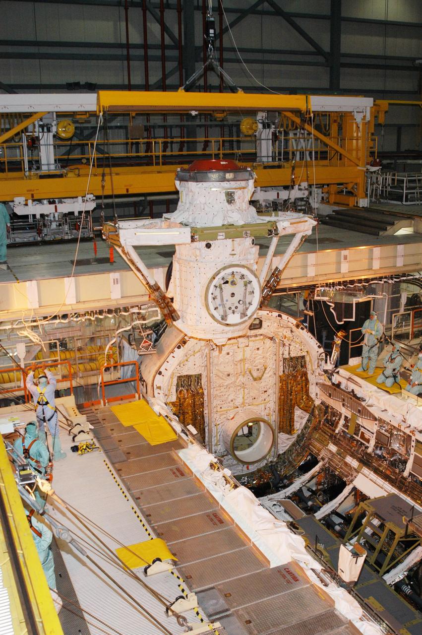
KENNEDY SPACE CENTER, FLA. -- Discovery’s airlock is ready for installation. Located inside the orbiter’s payload bay, the airlock is sized to accommodate two fully suited flight crew members simultaneously. Support functions include airlock depressurization and repressurization, extravehicular activity equipment recharge, liquid-cooled garment water cooling, EVA equipment checkout, and communications. Discovery is designated as the Return to Flight vehicle for mission STS-114, no earlier than March 2005. STS-114 mission is Logistics Flight 1, which is scheduled to deliver supplies and equipment plus the external stowage platform to the International Space Station.
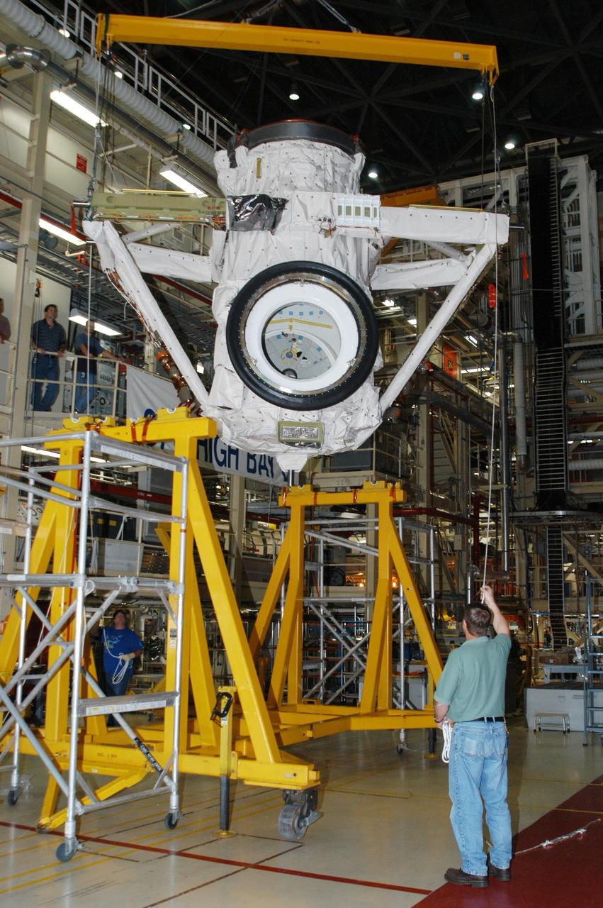
KENNEDY SPACE CENTER, FLA. -- Discovery’s airlock is lifted toward the orbiter for installation inside the orbiter’s payload bay. The airlock is sized to accommodate two fully suited flight crew members simultaneously. Support functions include airlock depressurization and repressurization, extravehicular activity equipment recharge, liquid-cooled garment water cooling, EVA equipment checkout, and communications. Discovery is designated as the Return to Flight vehicle for mission STS-114, no earlier than March 2005. STS-114 mission is Logistics Flight 1, which is scheduled to deliver supplies and equipment plus the external stowage platform to the International Space Station.
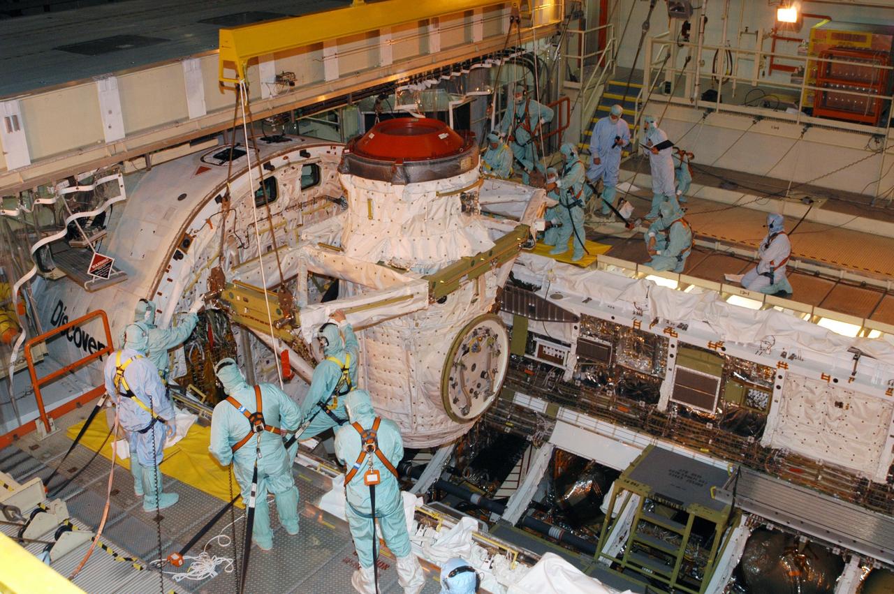
KENNEDY SPACE CENTER, FLA. -- Technicians in the Orbiter Processing Facility help guide Discovery’s airlock as a crane lowers it into the orbiter’s payload bay for installation. The airlock is sized to accommodate two fully suited flight crew members simultaneously. Support functions include airlock depressurization and repressurization, extravehicular activity equipment recharge, liquid-cooled garment water cooling, EVA equipment checkout, and communications. Discovery is designated as the Return to Flight vehicle for mission STS-114, no earlier than March 2005. STS-114 mission is Logistics Flight 1, which is scheduled to deliver supplies and equipment plus the external stowage platform to the International Space Station.
KENNEDY SPACE CENTER, FLA. -- Discovery’s airlock is lowered toward the orbiter’s payload bay for installation. The airlock is sized to accommodate two fully suited flight crew members simultaneously. Support functions include airlock depressurization and repressurization, extravehicular activity equipment recharge, liquid-cooled garment water cooling, EVA equipment checkout, and communications. Discovery is designated as the Return to Flight vehicle for mission STS-114, no earlier than March 2005. STS-114 mission is Logistics Flight 1, which is scheduled to deliver supplies and equipment plus the external stowage platform to the International Space Station.

KENNEDY SPACE CENTER, FLA. -- Technicians in the Orbiter Processing Facility attach a crane to Discovery’s airlock before lifting it for installation. The airlock is located inside the orbiter’s payload bay and is sized to accommodate two fully suited flight crew members simultaneously. Support functions include airlock depressurization and repressurization, extravehicular activity equipment recharge, liquid-cooled garment water cooling, EVA equipment checkout, and communications. Discovery is designated as the Return to Flight vehicle for mission STS-114, no earlier than March 2005. STS-114 mission is Logistics Flight 1, which is scheduled to deliver supplies and equipment plus the external stowage platform to the International Space Station.

A portion of the Radiological Control Center at NASA's Kennedy Space Center is seen during ceremonies to name the facility in honor of Randy Scott. A professional health physicist of more than 40 years, Scott served as the Florida spaceport's Radiation Protection Officer for 14 years until his death June 17, 2016. Located in the Neil Armstrong Operations and Checkout building, the Randall E. Scott Radiological Control Center is staffed by technical and radiological experts from NASA, the U.S. Department of Energy, the U.S. Air Force 45th Space Wing and the state of Florida. The group performs data collection and assessment functions supporting launch site and field data collection activities.
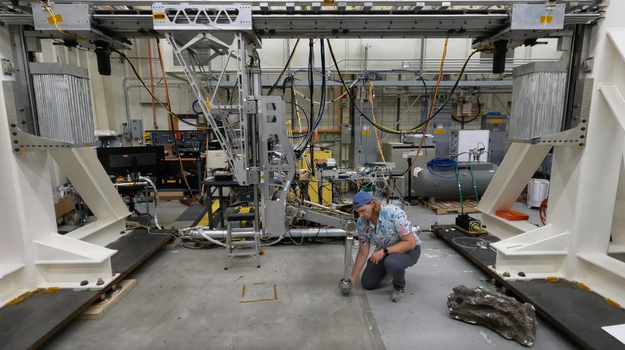
Engineer Matthew Cameron-Hooper performs a checkout on some systems of the Europa Lander landing gear testbed at NASA's Jet Propulsion Laboratory in Southern California on May 27, 2022. Europa Lander is a concept for a potential future mission that would look for signs of life in the icy surface material of Jupiter's moon Europa. The moon is thought to contain a global ocean of salty water beneath its frozen crust. If life exists in that ocean, signs of its existence called biosignatures could potentially find their way to the surface. In this mission concept, a spacecraft would land on Europa and collect and study samples from about 4 inches (10 centimeters) beneath the surface, looking for signs of life. The Europa Lander landing gear testbed was developed to test and inform the design of the landing gear for the spacecraft: It mimics the landing loads and ground interaction forces that a single flight landing gear would experience when touching down on the Europan surface. It does this by using gravity offloading to simulate the reduced gravity on Europa, and by replicating the mass and inertial properties of a flight lander as well as all the degrees of freedom that the landing gear would experience. This system checkout confirmed two critical functionalities of the testbed: low friction of the horizontal degree of freedom that carries the test landing gear, and proper functioning of the gravity offloading system. Together these functionalities ensure that only ground interaction forces cause the test landing gear to come to a stop during a test, just as a flight landing gear would experience when landing on the Europan surface. Video available at https://photojournal.jpl.nasa.gov/catalog/PIA26200
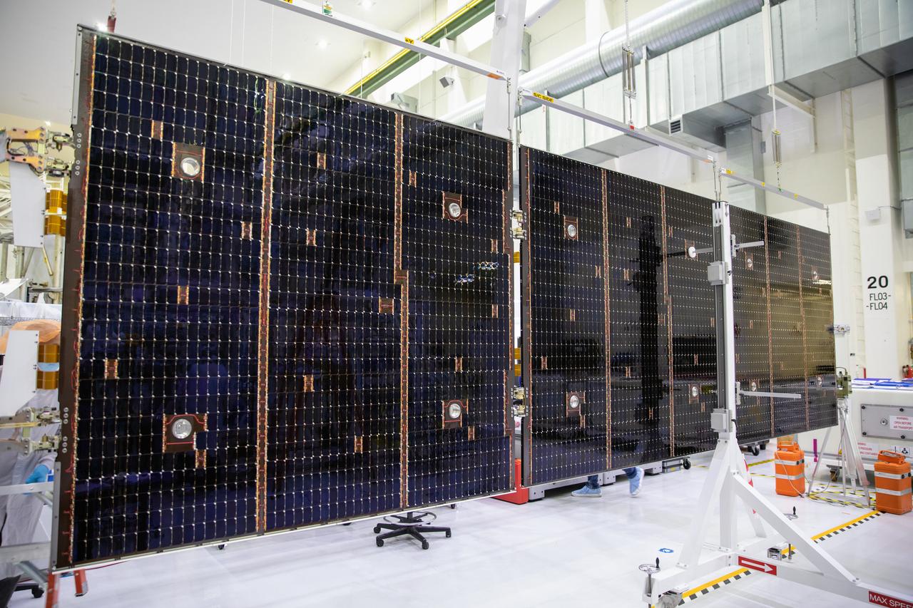
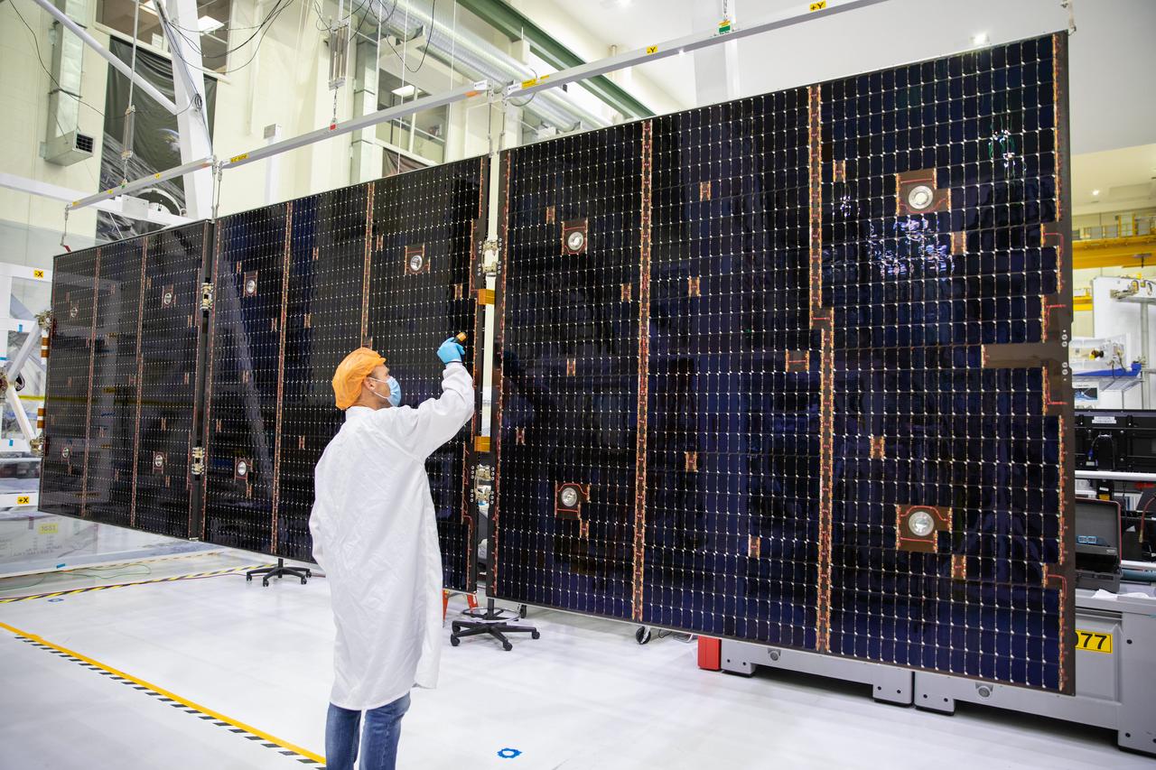
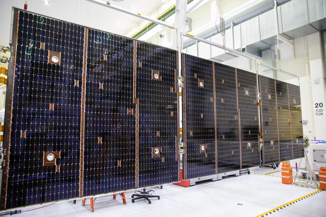
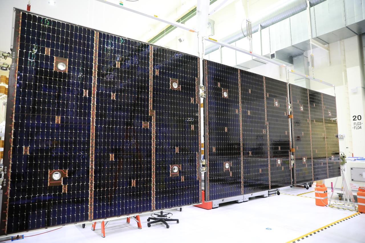
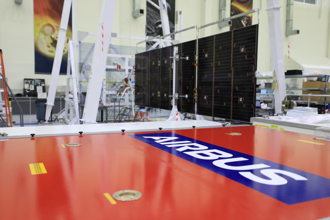
Inside the Neil Armstrong Operations and Checkout Building high bay at NASA’s Kennedy Space Center in Florida, in preparation for installation on the Artemis I spacecraft, technicians have extended one of the Artemis I solar array wings for inspection on Sept. 10, 2020, to confirm that it unfurled properly and all of the mechanisms functioned as expected. The solar array is one of four panels that will generate 11 kilowatts of power and span about 63 feet. The array is a component of Orion’s service module, which is provided by the European Space Agency and built by Airbus Defence and Space to supply Orion’s power, propulsion, air and water. The first in a series of increasingly complex missions, Artemis I will test the Orion spacecraft and Space Launch System as an integrated system ahead of crewed flights to the Moon. Under the Artemis program, NASA will land the first woman and the next man on the Moon in 2024.
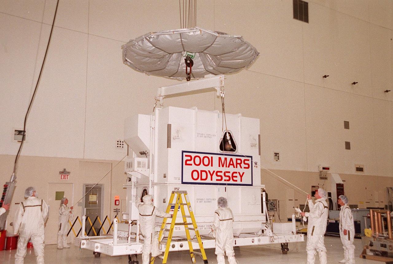
Workers in the Spacecraft Assembly and Encapsulation Facility 2 (SAEF-2)secure an overhead crane to the crate containing the Mars Odyssey spacecraft. The spacecraft will undergo final assembly and checkout, which includes installation of two of the three science instruments, integration of the three-panel solar array, and a spacecraft functional test. Launch aboard a Boeing Delta II launch vehicle from Pad A, Complex 17, CCAFS, is planned for April 7, 2001 the first day of a 21-day planetary window. The spacecraft will arrive at Mars on Oct. 20, 2001, for insertion into an initial elliptical capture orbit. Its final operational altitude will be a 250-mile-high, Sun-synchronous polar orbit. Mars Odyssey will spend two years mapping the planet’s surface and measuring its environment
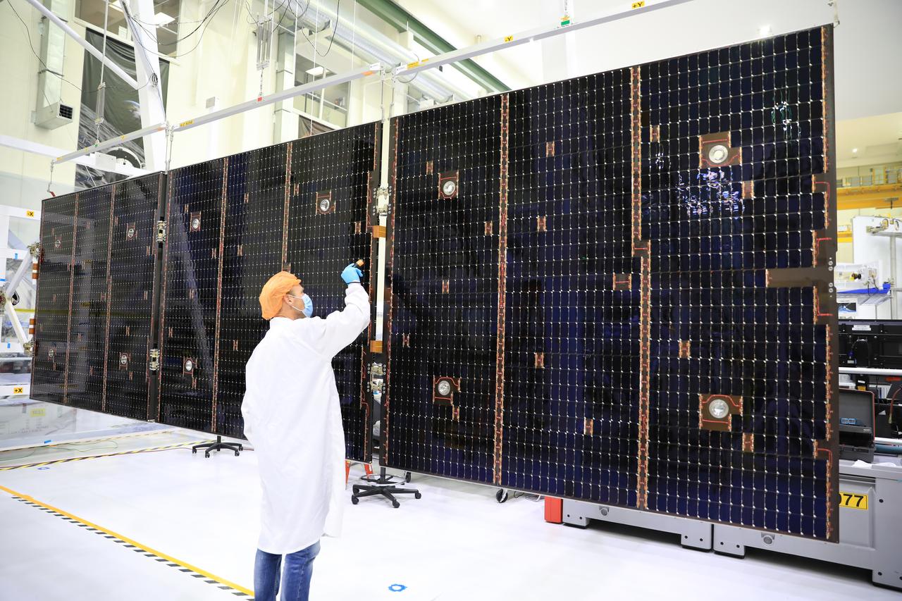
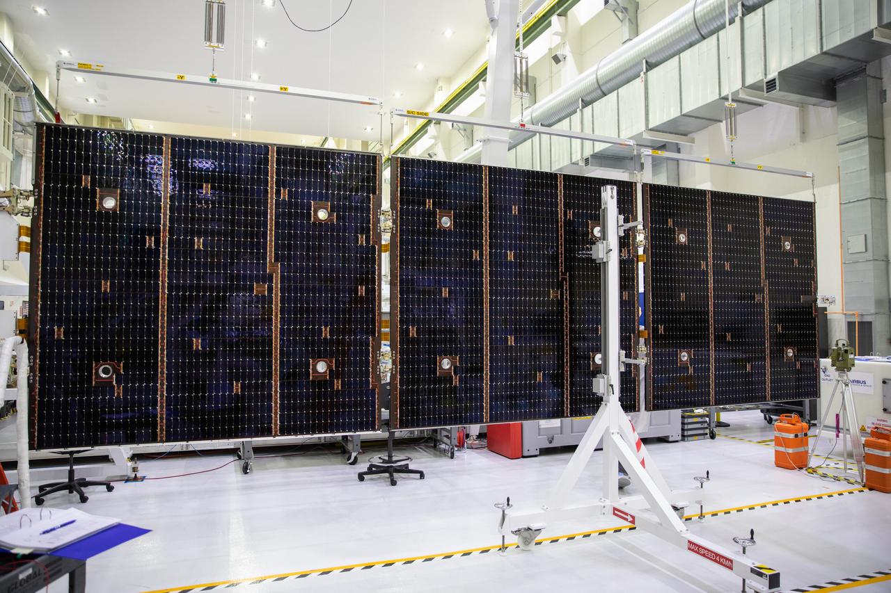
Inside the Neil Armstrong Operations and Checkout Building high bay at NASA’s Kennedy Space Center in Florida, in preparation for installation on the Artemis I spacecraft, technicians have extended one of the Artemis I solar array wings for inspection on Sept. 10, 2020, to confirm that it unfurled properly and all of the mechanisms functioned as expected. The solar array is one of four panels that will generate 11 kilowatts of power and span about 63 feet. The array is a component of Orion’s service module, which is provided by the European Space Agency and built by Airbus Defence and Space to supply Orion’s power, propulsion, air and water. The first in a series of increasingly complex missions, Artemis I will test the Orion spacecraft and Space Launch System as an integrated system ahead of crewed flights to the Moon.
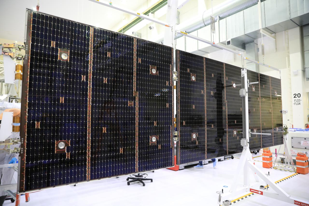
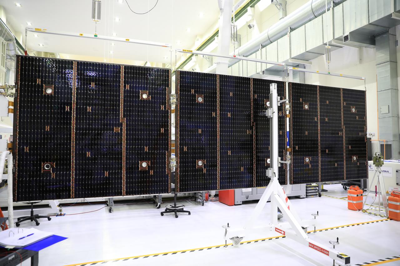
Inside the Neil Armstrong Operations and Checkout Building high bay at NASA’s Kennedy Space Center in Florida, in preparation for installation on the Artemis I spacecraft, technicians have extended one of the Artemis I solar array wings for inspection on Sept. 10, 2020, to confirm that it unfurled properly and all of the mechanisms functioned as expected. The solar array is one of four panels that will generate 11 kilowatts of power and span about 63 feet. The array is a component of Orion’s service module, which is provided by the European Space Agency and built by Airbus Defence and Space to supply Orion’s power, propulsion, air and water. The first in a series of increasingly complex missions, Artemis I will test the Orion spacecraft and Space Launch System as an integrated system ahead of crewed flights to the Moon.
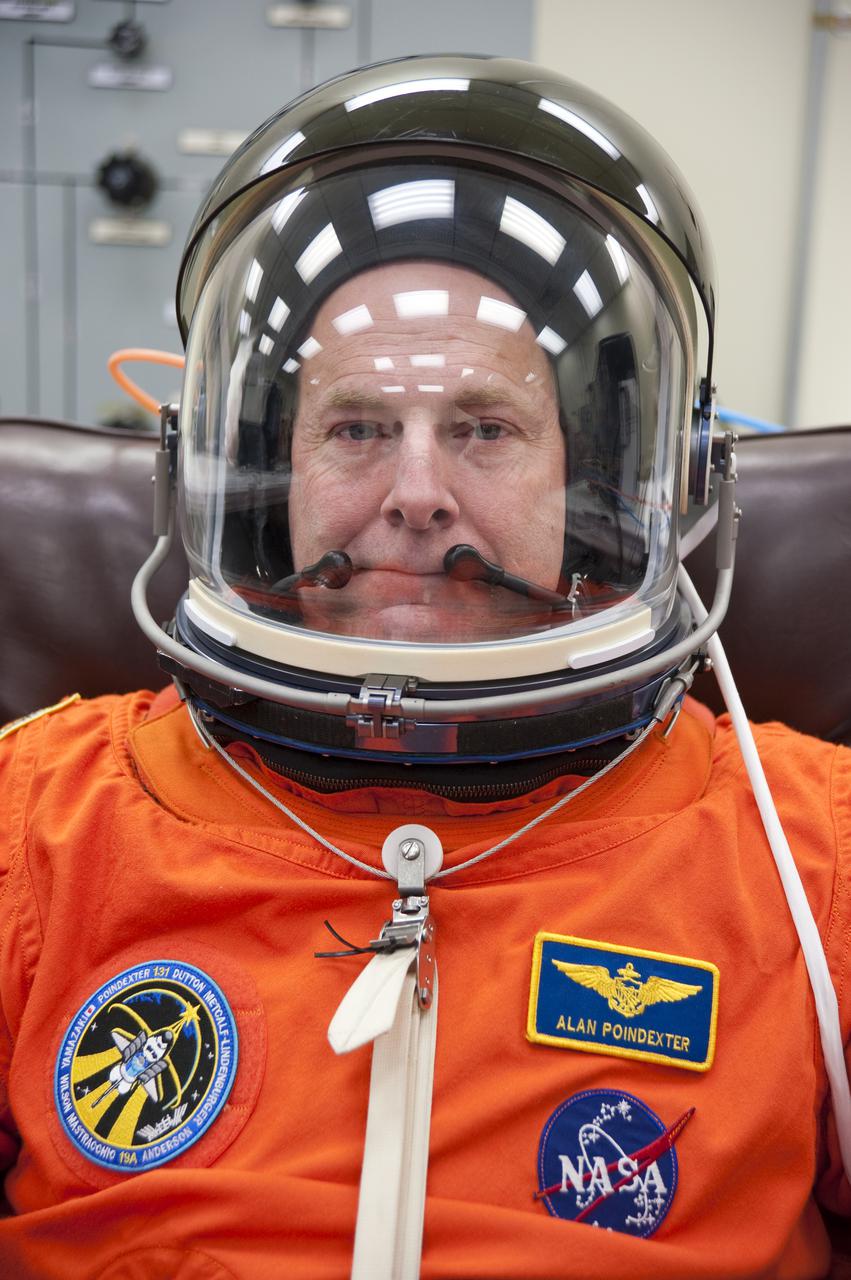
CAPE CANAVERAL, Fla. - In the Operations and Checkout Building at NASA's Kennedy Space Center in Florida, STS-131 Commander Alan Poindexter verifies that his helmet is functioning properly. The members of space shuttle Discovery's STS-131 crew put on their launch-and-entry suits before heading to the Astrovan for the ride to Launch Pad 39A. The crew is participating in the Terminal Countdown Demonstration Test, or TCDT, a dress rehearsal for launch. TCDT includes training on the emergency egress systems at the launch pad, driving practice of the M-113 armored personnel carrier and a simulated launch countdown. The crew will deliver the multi-purpose logistics module Leonard, filled with resupply stowage platforms and science racks, to the International Space Station. STS-131, targeted for launch on April 5, will be the 33rd shuttle mission to the station and the 131st shuttle mission overall. For information on the STS-131 mission and crew, visit http:__www.nasa.gov_mission_pages_shuttle_shuttlemissions_sts131_index.htm. Photo credit: NASA_Kim Shiflett
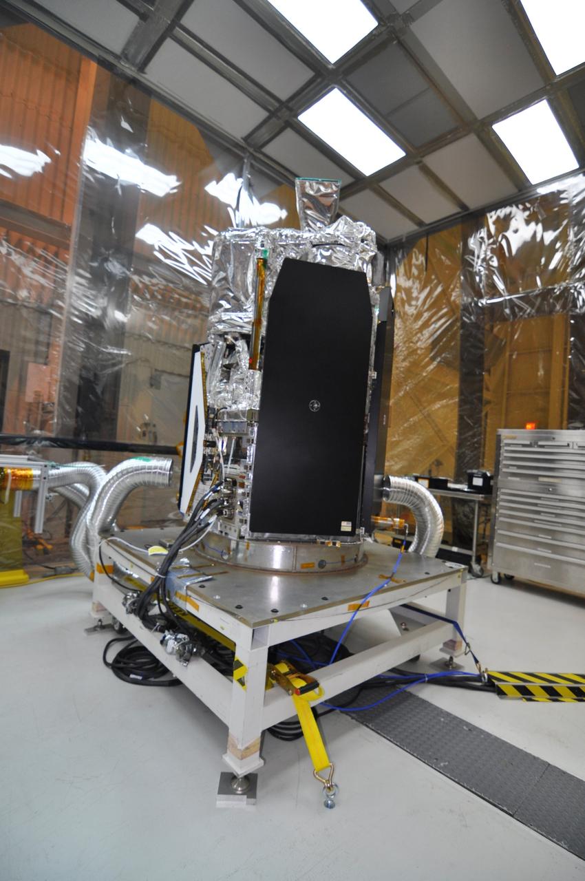
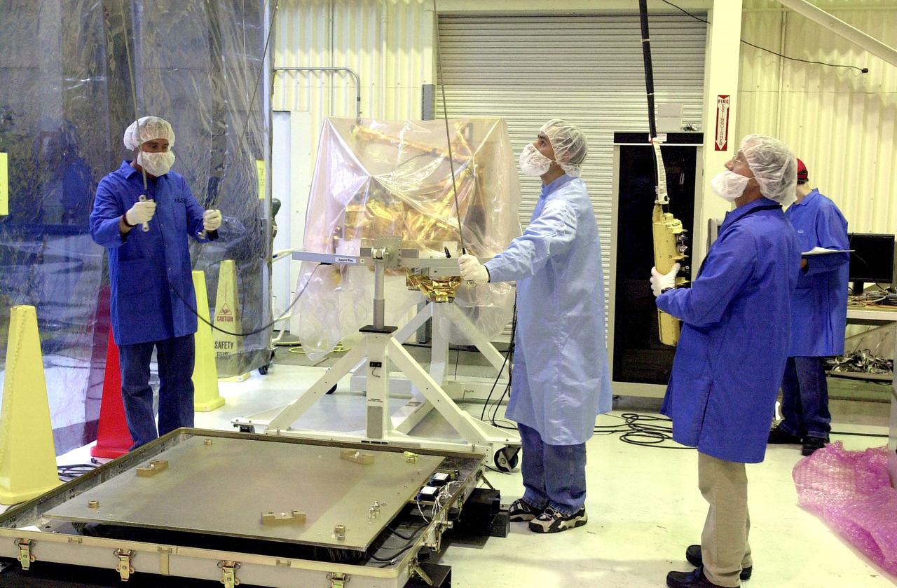
VANDENBERG AIR FORCE BASE, Calif. -- In a clean room at Vandenberg Air Force Base's processing facility in California, NASA's NuSTAR spacecraft undergoes a limited performance test, a two-day functional checkout of the spacecraft. A Pegasus XL rocket is set to launch NuSTAR into space. Once the rocket and spacecraft are processed at Vandenberg, they will be flown on the Orbital Sciences’ L-1011 carrier aircraft to the Ronald Reagan Ballistic Missile Defense Test Site at the Pacific Ocean’s Kwajalein Atoll for launch. The high-energy x-ray telescope will conduct a census for black holes, map radioactive material in young supernovae remnants, and study the origins of cosmic rays and the extreme physics around collapsed stars. For more information, visit science.nasa.gov/missions/nustar/. Photo credit: NASA/Randy Beaudoin, VAFB
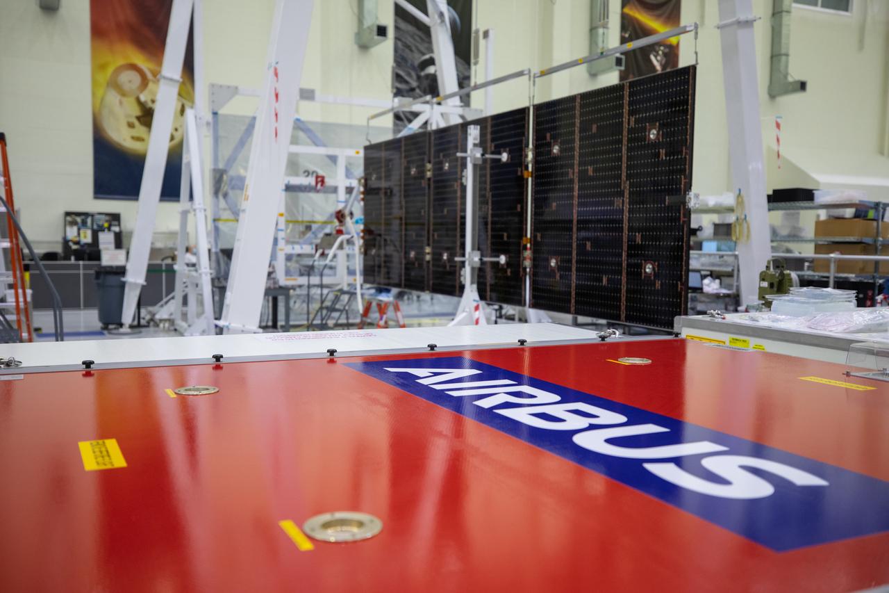
Inside the Neil Armstrong Operations and Checkout Building high bay at NASA’s Kennedy Space Center in Florida, in preparation for installation on the Artemis I spacecraft, technicians have extended one of the Artemis I solar array wings for inspection on Sept. 10, 2020, to confirm that it unfurled properly and all of the mechanisms functioned as expected. The solar array is one of four panels that will generate 11 kilowatts of power and span about 63 feet. The array is a component of Orion’s service module, which is provided by the European Space Agency and built by Airbus Defence and Space to supply Orion’s power, propulsion, air and water. The first in a series of increasingly complex missions, Artemis I will test the Orion spacecraft and Space Launch System as an integrated system ahead of crewed flights to the Moon. Under the Artemis program, NASA will land the first woman and the next man on the Moon in 2024.
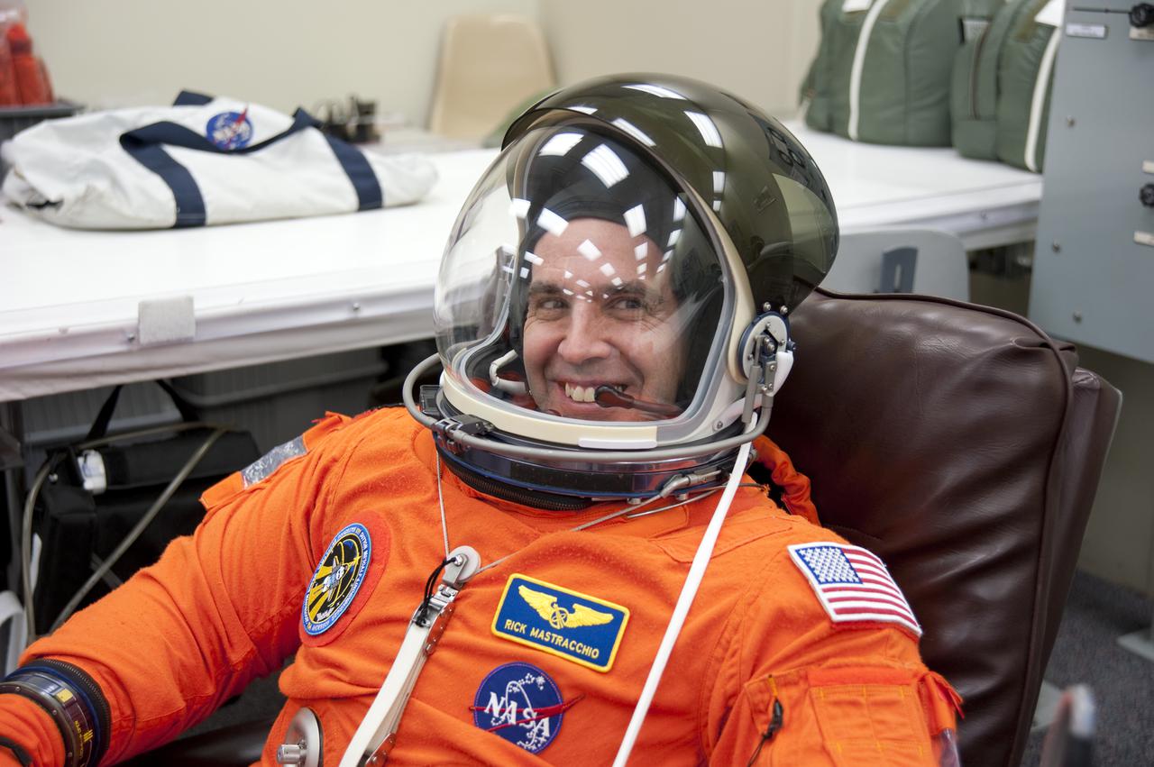
CAPE CANAVERAL, Fla. - In the Operations and Checkout Building at NASA's Kennedy Space Center in Florida, STS-131 Mission Specialist Rick Mastracchio verifies that his helmet is functioning properly. The members of space shuttle Discovery's STS-131 crew put on their launch-and-entry suits before heading to the Astrovan for the ride to Launch Pad 39A. The crew is participating in the Terminal Countdown Demonstration Test, or TCDT, a dress rehearsal for launch. TCDT includes training on the emergency egress systems at the launch pad, driving practice of the M-113 armored personnel carrier and a simulated launch countdown. The crew will deliver the multi-purpose logistics module Leonard, filled with resupply stowage platforms and science racks, to the International Space Station. STS-131, targeted for launch on April 5, will be the 33rd shuttle mission to the station and the 131st shuttle mission overall. For information on the STS-131 mission and crew, visit http:__www.nasa.gov_mission_pages_shuttle_shuttlemissions_sts131_index.htm. Photo credit: NASA_Kim Shiflett
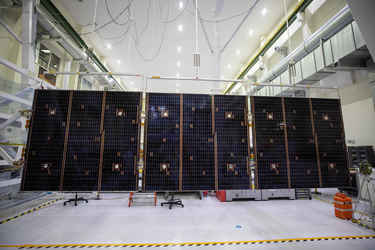
Inside the Neil Armstrong Operations and Checkout Building high bay at NASA’s Kennedy Space Center in Florida, in preparation for installation on the Artemis I spacecraft, technicians have extended one of the Artemis I solar array wings for inspection on Sept. 10, 2020, to confirm that it unfurled properly and all of the mechanisms functioned as expected. The solar array is one of four panels that will generate 11 kilowatts of power and span about 63 feet. The array is a component of Orion’s service module, which is provided by the European Space Agency and built by Airbus Defence and Space to supply Orion’s power, propulsion, air and water. The first in a series of increasingly complex missions, Artemis I will test the Orion spacecraft and Space Launch System as an integrated system ahead of crewed flights to the Moon. Under the Artemis program, NASA will land the first woman and the next man on the Moon in 2024.
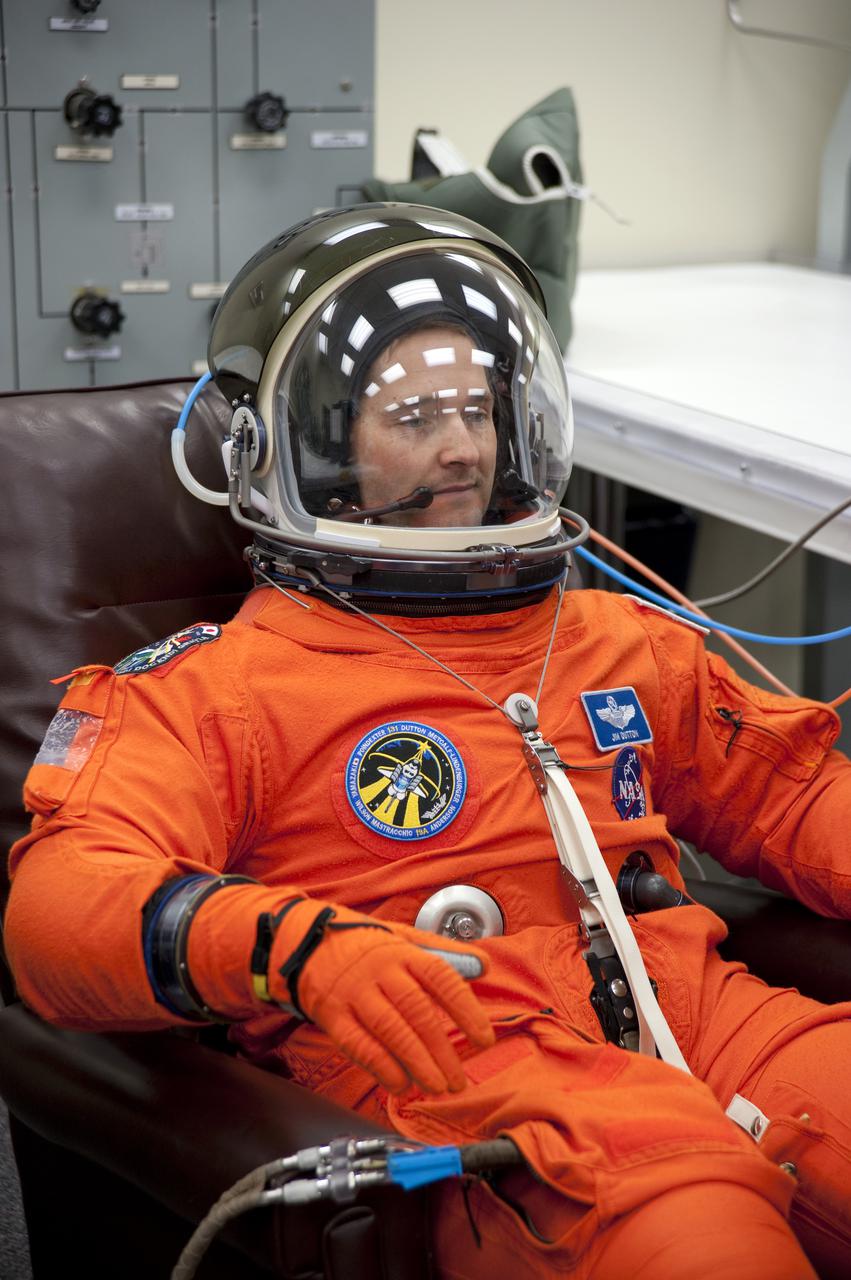
CAPE CANAVERAL, Fla. - In the Operations and Checkout Building at NASA's Kennedy Space Center in Florida, STS-131 Pilot James P. Dutton Jr. verifies that his helmet is functioning properly. The members of space shuttle Discovery's STS-131 crew put on their launch-and-entry suits before heading to the Astrovan for the ride to Launch Pad 39A. The crew is participating in the Terminal Countdown Demonstration Test, or TCDT, a dress rehearsal for launch. TCDT includes training on the emergency egress systems at the launch pad, driving practice of the M-113 armored personnel carrier and a simulated launch countdown. The crew will deliver the multi-purpose logistics module Leonard, filled with resupply stowage platforms and science racks, to the International Space Station. STS-131, targeted for launch on April 5, will be the 33rd shuttle mission to the station and the 131st shuttle mission overall. For information on the STS-131 mission and crew, visit http:__www.nasa.gov_mission_pages_shuttle_shuttlemissions_sts131_index.htm. Photo credit: NASA_Kim Shiflett
Inside the Neil Armstrong Operations and Checkout Building high bay at NASA’s Kennedy Space Center in Florida, in preparation for installation on the Artemis I spacecraft, technicians have extended one of the Artemis I solar array wings for inspection on Sept. 10, 2020, to confirm that it unfurled properly and all of the mechanisms functioned as expected. The solar array is one of four panels that will generate 11 kilowatts of power and span about 63 feet. The array is a component of Orion’s service module, which is provided by the European Space Agency and built by Airbus Defence and Space to supply Orion’s power, propulsion, air and water. The first in a series of increasingly complex missions, Artemis I will test the Orion spacecraft and Space Launch System as an integrated system ahead of crewed flights to the Moon. Under the Artemis program, NASA will land the first woman and the next man on the Moon in 2024.
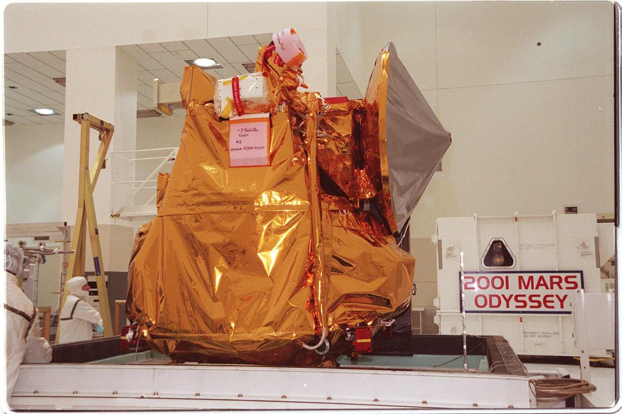
In the Spacecraft Assembly and Encapsulation Facility 2, the 2001 Mars Odyssey spacecraft sits on a workstand, ready for final assembly and checkout. That includes installation of two of the three science instruments, integration of the three-panel solar array, and a spacecraft functional test. Odyssey, which arrived from Denver, Colo., Jan. 4, will be launched aboard a Boeing Delta II vehicle from Pad A, Complex 17, CCAFS. Launch is planned for April 7, 2001 the first day of a 21-day planetary window. The spacecraft will arrive at Mars on Oct. 20, 2001, for insertion into an initial elliptical capture orbit. Its final operational altitude will be a 250-mile-high, Sun-synchronous polar orbit. Mars Odyssey will spend two years mapping the planet’s surface and measuring its environment
Inside the Neil Armstrong Operations and Checkout Building high bay at NASA’s Kennedy Space Center in Florida, in preparation for installation on the Artemis I spacecraft, technicians have extended one of the Artemis I solar array wings for inspection on Sept. 10, 2020, to confirm that it unfurled properly and all of the mechanisms functioned as expected. The solar array is one of four panels that will generate 11 kilowatts of power and span about 63 feet. The array is a component of Orion’s service module, which is provided by the European Space Agency and built by Airbus Defence and Space to supply Orion’s power, propulsion, air and water. The first in a series of increasingly complex missions, Artemis I will test the Orion spacecraft and Space Launch System as an integrated system ahead of crewed flights to the Moon. Under the Artemis program, NASA will land the first woman and the next man on the Moon in 2024.
Inside the Neil Armstrong Operations and Checkout Building high bay at NASA’s Kennedy Space Center in Florida, in preparation for installation on the Artemis I spacecraft, technicians have extended one of the Artemis I solar array wings for inspection on Sept. 10, 2020, to confirm that it unfurled properly and all of the mechanisms functioned as expected. The solar array is one of four panels that will generate 11 kilowatts of power and span about 63 feet. The array is a component of Orion’s service module, which is provided by the European Space Agency and built by Airbus Defence and Space to supply Orion’s power, propulsion, air and water. The first in a series of increasingly complex missions, Artemis I will test the Orion spacecraft and Space Launch System as an integrated system ahead of crewed flights to the Moon.
Inside the Neil Armstrong Operations and Checkout Building high bay at NASA’s Kennedy Space Center in Florida, in preparation for installation on the Artemis I spacecraft, technicians have extended one of the Artemis I solar array wings for inspection on Sept. 10, 2020, to confirm that it unfurled properly and all of the mechanisms functioned as expected. The solar array is one of four panels that will generate 11 kilowatts of power and span about 63 feet. The array is a component of Orion’s service module, which is provided by the European Space Agency and built by Airbus Defence and Space to supply Orion’s power, propulsion, air and water. The first in a series of increasingly complex missions, Artemis I will test the Orion spacecraft and Space Launch System as an integrated system ahead of crewed flights to the Moon. Under the Artemis program, NASA will land the first woman and the next man on the Moon in 2024.
In the Spacecraft Assembly and Encapsulation Facility 2, workers place a protective barrier around the 2001 Mars Odyssey spacecraft. Odyssey will undergo final assembly and checkout in the SAEf-2, which includes installation of two of the three science instruments, integration of the three-panel solar array, and a spacecraft functional test. Odyssey, which arrived from Denver, Colo., Jan. 4, will be launched aboard a Boeing Delta II vehicle from Pad A, Complex 17, CCAFS. Launch is planned for April 7, 2001 the first day of a 21-day planetary window. The spacecraft will arrive at Mars on Oct. 20, 2001, for insertion into an initial elliptical capture orbit. Its final operational altitude will be a 250-mile-high, Sun-synchronous polar orbit. Mars Odyssey will spend two years mapping the planet’s surface and measuring its environment
Inside the Neil Armstrong Operations and Checkout Building high bay at NASA’s Kennedy Space Center in Florida, in preparation for installation on the Artemis I spacecraft, technicians have extended one of the Artemis I solar array wings for inspection on Sept. 10, 2020, to confirm that it unfurled properly and all of the mechanisms functioned as expected. The solar array is one of four panels that will generate 11 kilowatts of power and span about 63 feet. The array is a component of Orion’s service module, which is provided by the European Space Agency and built by Airbus Defence and Space to supply Orion’s power, propulsion, air and water. The first in a series of increasingly complex missions, Artemis I will test the Orion spacecraft and Space Launch System as an integrated system ahead of crewed flights to the Moon.
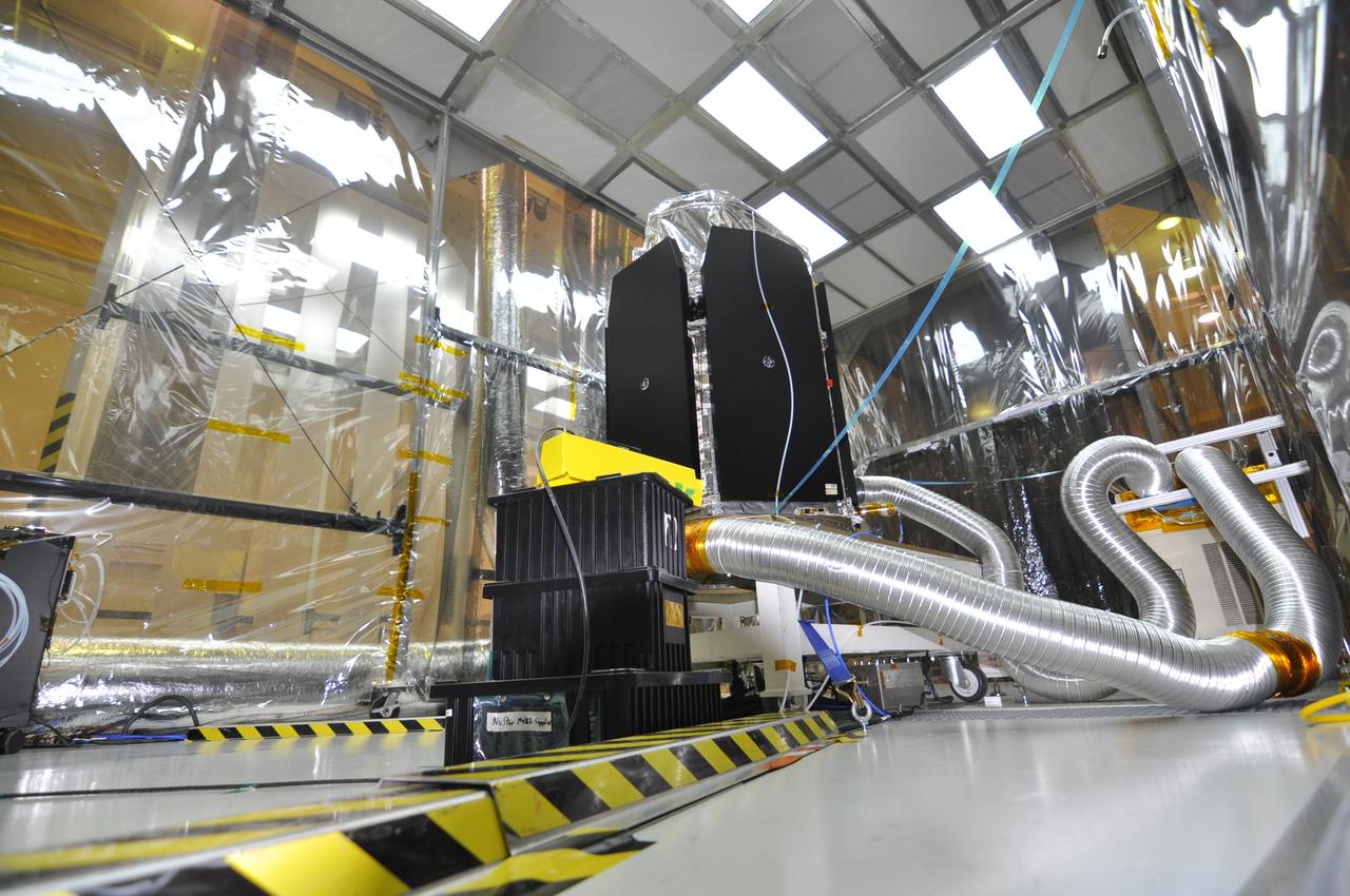
VANDENBERG AIR FORCE BASE, Calif. -- In a clean room at Vandenberg Air Force Base's processing facility in California, NASA's NuSTAR spacecraft undergoes a limited performance test, a two-day functional checkout of the spacecraft. A Pegasus XL rocket is set to launch NuSTAR into space. Once the rocket and spacecraft are processed at Vandenberg, they will be flown on the Orbital Sciences’ L-1011 carrier aircraft to the Ronald Reagan Ballistic Missile Defense Test Site at the Pacific Ocean’s Kwajalein Atoll for launch. The high-energy x-ray telescope will conduct a census for black holes, map radioactive material in young supernovae remnants, and study the origins of cosmic rays and the extreme physics around collapsed stars. For more information, visit science.nasa.gov/missions/nustar/. Photo credit: NASA/Randy Beaudoin, VAFB

A Mars Science Laboratory cap is displayed in the Randall E. Scott Radiological Control Center at NASA's Kennedy Space Center. The facility was recently named in honor of Randy Scott, a professional health physicist of more than 40 years. He served as the Florida spaceport's Radiation Protection Officer for 14 years until his death June 17, 2016. Launched Nov. 26, 2011, the Mars Science Laboratory with the Curiosity lander was powered by a radioisotope thermalelectric generator. Located in the Neil Armstrong Operations and Checkout building, the Randall E. Scott Radiological Control Center is staffed by technical and radiological experts from NASA, the U.S. Department of Energy, the U.S. Air Force 45th Space Wing and the state of Florida. The group performs data collection and assessment functions supporting launch site and field data collection activities during launces involving plutonium-powered spacecraft such as the Mars Science Laboratory.
Inside the Neil Armstrong Operations and Checkout Building high bay at NASA’s Kennedy Space Center in Florida, in preparation for installation on the Artemis I spacecraft, technicians have extended one of the Artemis I solar array wings for inspection on Sept. 10, 2020, to confirm that it unfurled properly and all of the mechanisms functioned as expected. The solar array is one of four panels that will generate 11 kilowatts of power and span about 63 feet. The array is a component of Orion’s service module, which is provided by the European Space Agency and built by Airbus Defence and Space to supply Orion’s power, propulsion, air and water. The first in a series of increasingly complex missions, Artemis I will test the Orion spacecraft and Space Launch System as an integrated system ahead of crewed flights to the Moon.
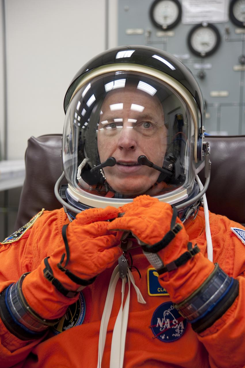
CAPE CANAVERAL, Fla. - In the Operations and Checkout Building at NASA's Kennedy Space Center in Florida, STS-131 Mission Specialist Clayton Anderson verifies that his helmet is functioning properly. The members of space shuttle Discovery's STS-131 crew put on their launch-and-entry suits before heading to the Astrovan for the ride to Launch Pad 39A. The crew is participating in the Terminal Countdown Demonstration Test, or TCDT, a dress rehearsal for launch. TCDT includes training on the emergency egress systems at the launch pad, driving practice of the M-113 armored personnel carrier and a simulated launch countdown. The crew will deliver the multi-purpose logistics module Leonard, filled with resupply stowage platforms and science racks, to the International Space Station. STS-131, targeted for launch on April 5, will be the 33rd shuttle mission to the station and the 131st shuttle mission overall. For information on the STS-131 mission and crew, visit http:__www.nasa.gov_mission_pages_shuttle_shuttlemissions_sts131_index.htm. Photo credit: NASA_Kim Shiflett
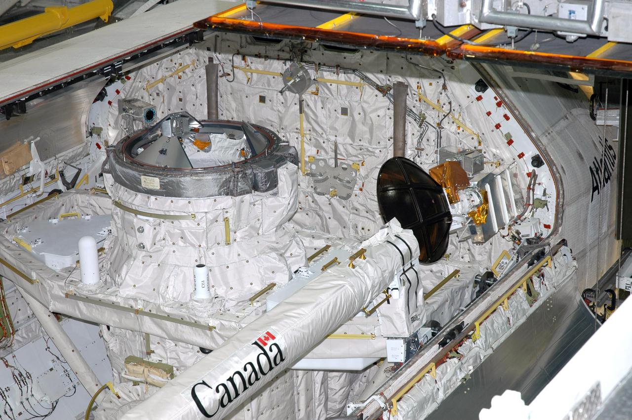
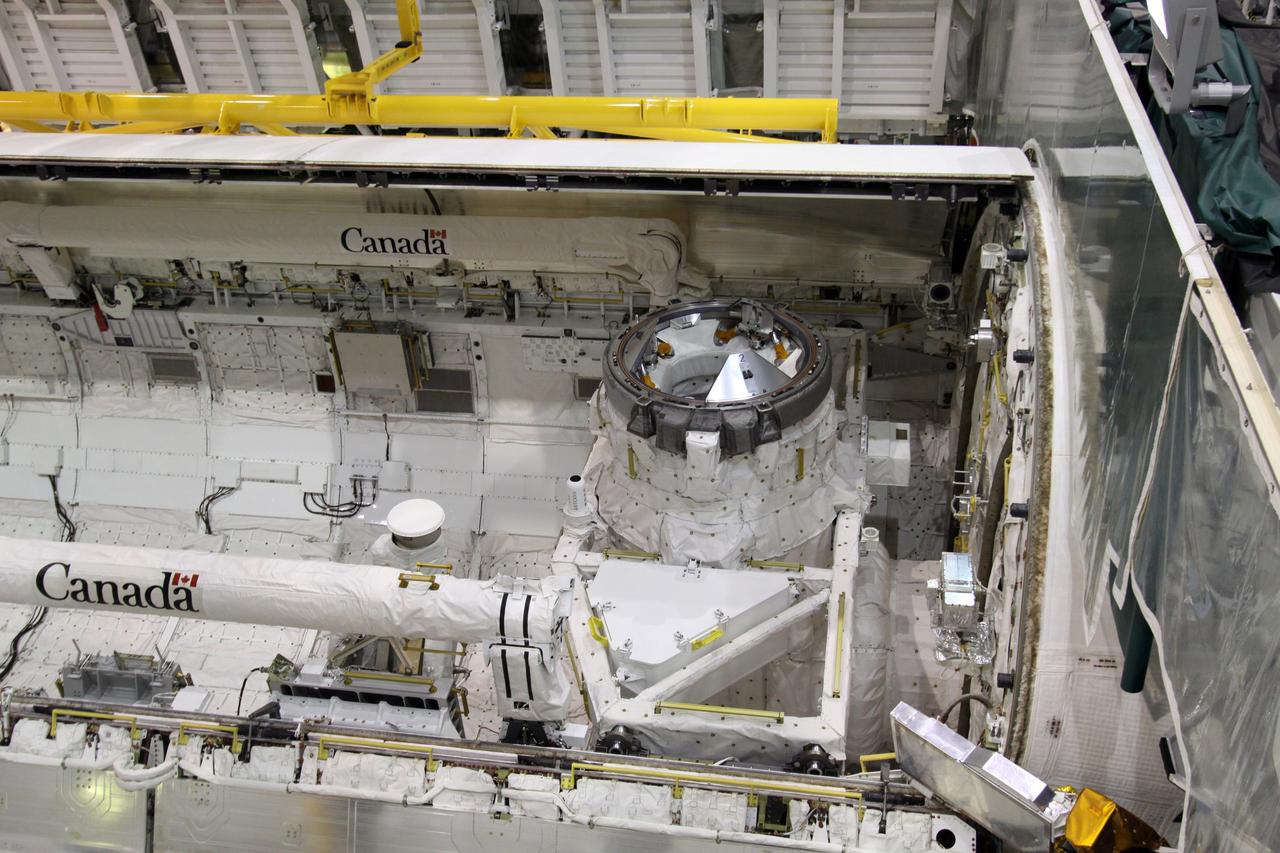
KENNEDY SPACE CENTER, FLA. - In the Orbiter Processing Facility at Kennedy Space Center in Florida, the payload bay doors of the orbiter Atlantis are being closed. The Orbiter Boom Sensor System (OBSS) is seen on the starboard side (right) of the payload bay. The 50-foot-long OBSS attaches to the Remote Manipulator System, or Shuttle arm, and is one of the new safety measures for Return to Flight. It equips the orbiter with cameras and laser systems to inspect the Shuttle’s Thermal Protection System while in space. At left of the OBSS is Atlantis’ airlock, which is sized to accommodate two fully suited flight crew members simultaneously. Support functions include airlock depressurization and repressurization, extravehicular activity equipment recharge, liquid-cooled garment water cooling, EVA equipment checkout, and communications. Atlantis is scheduled to fly on the second Return to Flight mission, STS-121, targeted for launch in a window extending from Sept. 9 to Sept. 24.

Inside the Neil Armstrong Operations and Checkout Building high bay at NASA’s Kennedy Space Center in Florida, in preparation for installation on the Artemis I spacecraft, technicians have extended one of the Artemis I solar array wings for inspection on Sept. 10, 2020, to confirm that it unfurled properly and all of the mechanisms functioned as expected. The solar array is one of four panels that will generate 11 kilowatts of power and span about 63 feet. The array is a component of Orion’s service module, which is provided by the European Space Agency and built by Airbus Defence and Space to supply Orion’s power, propulsion, air and water. The first in a series of increasingly complex missions, Artemis I will test the Orion spacecraft and Space Launch System as an integrated system ahead of crewed flights to the Moon. Under the Artemis program, NASA will land the first woman and the next man on the Moon in 2024.

Workers in the Spacecraft Assembly and Encapsulation Facility 2 move the shipping crate away from the 2001 Mars Odyssey spacecraft, at left on the stand. Odyssey is still covered by a protective sheet. The spacecraft, which arrived from Denver, Colo., Jan. 4, will undergo final assembly and checkout in the SAEF-2. That includes installation of two of the three science instruments, integration of the three-panel solar array, and a spacecraft functional test. Launch aboard a Boeing Delta II launch vehicle from Pad A, Complex 17, CCAFS, is planned for April 7, 2001 the first day of a 21-day planetary window. The spacecraft will arrive at Mars on Oct. 20, 2001, for insertion into an initial elliptical capture orbit. Its final operational altitude will be a 250-mile-high, Sun-synchronous polar orbit. Mars Odyssey will spend two years mapping the planet’s surface and measuring its environment

In the Spacecraft Assembly and Encapsulation Facility 2 , an overhead crane lifts the crate covering the Mars Odyssey spacecraft. The spacecraft, which arrived from Denver, Colo., Jan. 4, will undergo final assembly and checkout. That includes installation of two of the three science instruments, integration of the three-panel solar array, and a spacecraft functional test. Launch aboard a Boeing Delta II launch vehicle from Pad A, Complex 17, CCAFS, is planned for April 7, 2001 the first day of a 21-day planetary window. The spacecraft will arrive at Mars on Oct. 20, 2001, for insertion into an initial elliptical capture orbit. Its final operational altitude will be a 250-mile-high, Sun-synchronous polar orbit. Mars Odyssey will spend two years mapping the planet’s surface and measuring its environment
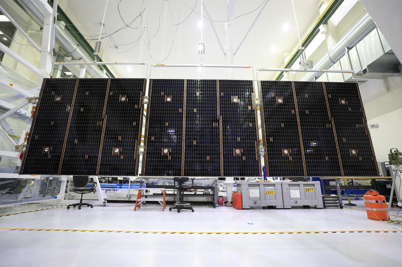
Inside the Neil Armstrong Operations and Checkout Building high bay at NASA’s Kennedy Space Center in Florida, in preparation for installation on the Artemis I spacecraft, technicians have extended one of the Artemis I solar array wings for inspection on Sept. 10, 2020, to confirm that it unfurled properly and all of the mechanisms functioned as expected. The solar array is one of four panels that will generate 11 kilowatts of power and span about 63 feet. The array is a component of Orion’s service module, which is provided by the European Space Agency and built by Airbus Defence and Space to supply Orion’s power, propulsion, air and water. The first in a series of increasingly complex missions, Artemis I will test the Orion spacecraft and Space Launch System as an integrated system ahead of crewed flights to the Moon.
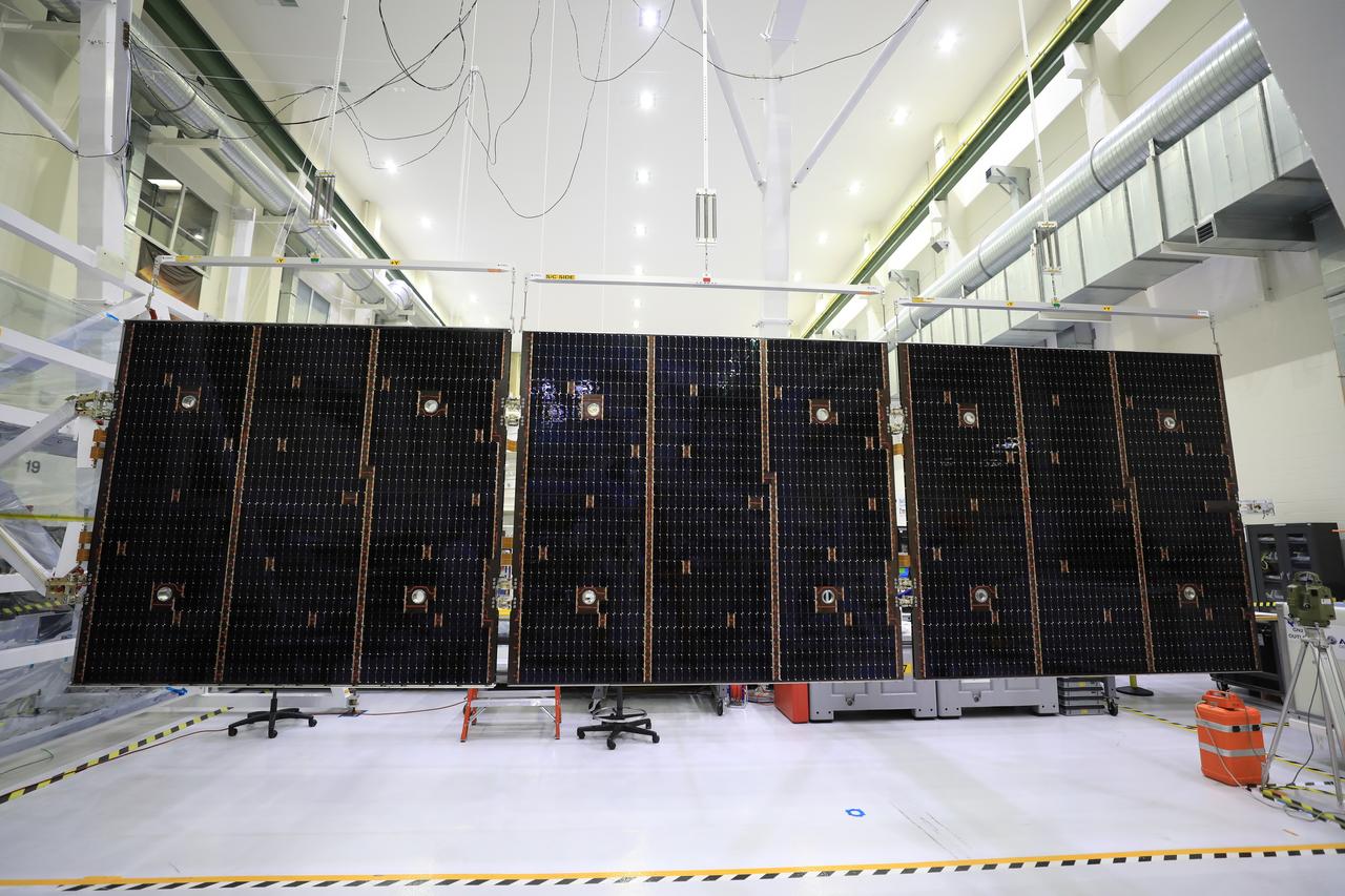
Inside the Neil Armstrong Operations and Checkout Building high bay at NASA’s Kennedy Space Center in Florida, in preparation for installation on the Artemis I spacecraft, technicians have extended one of the Artemis I solar array wings for inspection on Sept. 10, 2020, to confirm that it unfurled properly and all of the mechanisms functioned as expected. The solar array is one of four panels that will generate 11 kilowatts of power and span about 63 feet. The array is a component of Orion’s service module, which is provided by the European Space Agency and built by Airbus Defence and Space to supply Orion’s power, propulsion, air and water. The first in a series of increasingly complex missions, Artemis I will test the Orion spacecraft and Space Launch System as an integrated system ahead of crewed flights to the Moon.

In the Spacecraft Assembly and Encapsulation Facility 2, workers remove the protective sheet from around the 2001 Mars Odyssey spacecraft. Odyssey, which arrived from Denver, Colo., Jan. 4, will undergo final assembly and checkout in the SAEF-2. That includes installation of two of the three science instruments, integration of the three-panel solar array, and a spacecraft functional test. Launch aboard a Boeing Delta II launch vehicle from Pad A, Complex 17, CCAFS, is planned for April 7, 2001 the first day of a 21-day planetary window. The spacecraft will arrive at Mars on Oct. 20, 2001, for insertion into an initial elliptical capture orbit. Its final operational altitude will be a 250-mile-high, Sun-synchronous polar orbit. Mars Odyssey will spend two years mapping the planet’s surface and measuring its environment
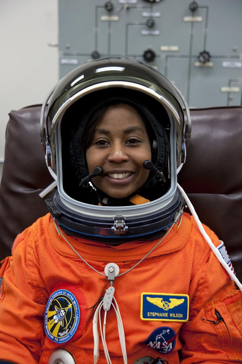
CAPE CANAVERAL, Fla. - In the Operations and Checkout Building at NASA's Kennedy Space Center in Florida, STS-131 Mission Specialist Stephanie Wilson verifies that her helmet is functioning properly. The members of space shuttle Discovery's STS-131 crew put on their launch-and-entry suits before heading to the Astrovan for the ride to Launch Pad 39A. The crew is participating in the Terminal Countdown Demonstration Test, or TCDT, a dress rehearsal for launch. TCDT includes training on the emergency egress systems at the launch pad, driving practice of the M-113 armored personnel carrier and a simulated launch countdown. The crew will deliver the multi-purpose logistics module Leonard, filled with resupply stowage platforms and science racks, to the International Space Station. STS-131, targeted for launch on April 5, will be the 33rd shuttle mission to the station and the 131st shuttle mission overall. For information on the STS-131 mission and crew, visit http:__www.nasa.gov_mission_pages_shuttle_shuttlemissions_sts131_index.htm. Photo credit: NASA_Kim Shiflett
KENNEDY SPACE CENTER, FLA. - In the Orbiter Processing Facility at Kennedy Space Center in Florida, the payload bay doors of the orbiter Atlantis are being closed. The Remote Manipulator System, or Shuttle arm, is seen on the port side (left) and the Orbiter Boom Sensor System (OBSS) is seen on the starboard side (right) of the payload bay. The 50-foot-long OBSS attaches to the Shuttle arm and is one of the new safety measures for Return to Flight. It equips the orbiter with cameras and laser systems to inspect the Shuttle’s Thermal Protection System while in space. Between them is Atlantis’ airlock, sized to accommodate two fully suited flight crew members simultaneously. Support functions include airlock depressurization and repressurization, extravehicular activity equipment recharge, liquid-cooled garment water cooling, EVA equipment checkout, and communications. Atlantis is scheduled to fly on the second Return to Flight mission, STS-121, targeted for launch in a window extending from Sept. 9 to Sept. 24.
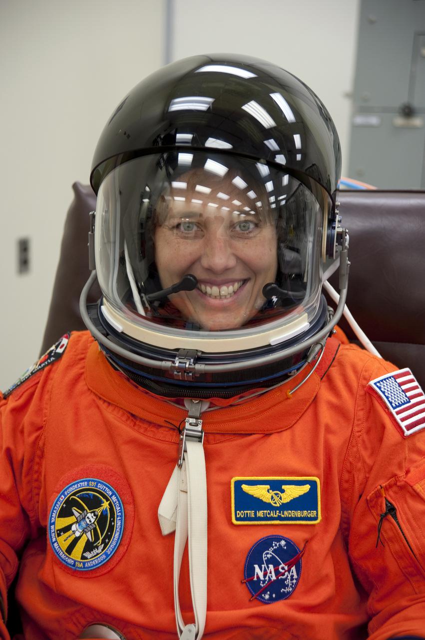
CAPE CANAVERAL, Fla. - In the Operations and Checkout Building at NASA's Kennedy Space Center in Florida, STS-131 Mission Specialist Dorothy Metcalf-Lindenburger verifies that her helmet is functioning properly. The members of space shuttle Discovery's STS-131 crew put on their launch-and-entry suits before heading to the Astrovan for the ride to Launch Pad 39A. The crew is participating in the Terminal Countdown Demonstration Test, or TCDT, a dress rehearsal for launch. TCDT includes training on the emergency egress systems at the launch pad, driving practice of the M-113 armored personnel carrier and a simulated launch countdown. The crew will deliver the multi-purpose logistics module Leonard, filled with resupply stowage platforms and science racks, to the International Space Station. STS-131, targeted for launch on April 5, will be the 33rd shuttle mission to the station and the 131st shuttle mission overall. For information on the STS-131 mission and crew, visit http:__www.nasa.gov_mission_pages_shuttle_shuttlemissions_sts131_index.htm. Photo credit: NASA_Kim Shiflett
CAPE CANAVERAL, Fla. – In Orbiter Processing Facility 1 at NASA's Kennedy Space Center in Florida, space shuttle Atlantis' payload bay doors are being closed. Inside the payload bay, at right, is seen the airlock, which is sized to accommodate two fully suited flight crew members simultaneously. Support functions include airlock depressurization and repressurization, extravehicular activity equipment recharge, liquid-cooled garment water cooling, EVA equipment checkout, and communications. The designated shuttle for the STS-129 mission, Atlantis will deliver to the International Space Station two spare gyroscopes, two nitrogen tank assemblies, two pump modules, an ammonia tank assembly and a spare latching end effector for the station's robotic arm. Atlantis is targeted to launch Nov. 12. Photo credit: NASA/Jack Pfaller

The 2001 Mars Odyssey spacecraft leaves the KSC Shuttle Landing Facility on the bed of a transport trailer. The spacecraft is being moved to the Spacecraft Assembly and Encapsulation Facility 2 (SAEF-2) located in the KSC Industrial Area. The spacecraft arrived at the SLF aboard an Air Force C-17 cargo airplane that brought it from Denver, Colo.., location of the Lockheed Martin plant where the spacecraft was built. In the SAEF, Odyssey will undergo final assembly and checkout. This includes installation of two of the three science instruments, integration of the three-panel solar array, and a spacecraft functional test. It will be fueled and then mated to an upper stage booster, the final activities before going to the launch pad. Launch is planned for April 7, 2001 the first day of a 21-day planetary window. Mars Odyssey will be inserted into an interplanetary trajectory by a Boeing Delta II launch vehicle from Pad A at Complex 17 at the Cape Canaveral Air Force Station, Fla. The spacecraft will arrive at Mars on Oct. 20, 2001, for insertion into an initial elliptical capture orbit. Its final operational altitude will be a 250-mile-high, Sun-synchronous polar orbit. Mars Odyssey will spend two years mapping the planet's surface and measuring its environment

The 2001 Mars Odyssey spacecraft arrives at the Spacecraft Assembly and Encapsulation Facility 2 (SAEF-2) located in the KSC Industrial Area. The spacecraft arrived at KSC's Shuttle Landing Facility aboard an Air Force C-17 cargo airplane that brought it from Denver, Colo.., location of the Lockheed Martin plant where the spacecraft was built. In the SAEF, Odyssey will undergo final assembly and checkout. This includes installation of two of the three science instruments, integration of the three-panel solar array, and a spacecraft functional test. It will be fueled and then mated to an upper stage booster, the final activities before going to the launch pad. Launch is planned for April 7, 2001 the first day of a 21-day planetary window. Mars Odyssey will be inserted into an interplanetary trajectory by a Boeing Delta II launch vehicle from Pad A at Complex 17 at the Cape Canaveral Air Force Station, Fla. The spacecraft will arrive at Mars on Oct. 20, 2001, for insertion into an initial elliptical capture orbit. Its final operational altitude will be a 250-mile-high, Sun-synchronous polar orbit. Mars Odyssey will spend two years mapping the planet's surface and measuring its environment
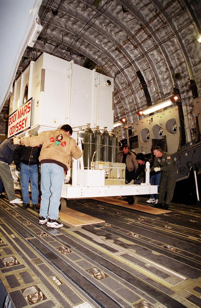
The Mars Odyssey spacecraft is maneuvered for removal from the Air Force C-17 cargo airplane that brought it from Denver, Colo.., location of the Lockheed Martin plant where the spacecraft was built. Mars Odyssey will be moved on a transport trailer from KSC's Shuttle Landing Facility to the Spacecraft Assembly and Encapsulation Facility 2 (SAEF-2) located in the KSC Industrial Area. In the SAEF it will undergo final assembly and checkout. This includes installation of two of the three science instruments, integration of the three-panel solar array, and a spacecraft functional test. It will be fueled and then mated to an upper stage booster, the final activities before going to the launch pad. Launch is planned for April 7, 2001 the first day of a 21-day planetary window. Mars Odyssey will be inserted into an interplanetary trajectory by a Boeing Delta II launch vehicle from Pad A at Complex 17 at the Cape Canaveral Air Force Station, Fla. The spacecraft will arrive at Mars on Oct. 20, 2001, for insertion into an initial elliptical capture orbit. Its final operational altitude will be a 250-mile-high, Sun-synchronous polar orbit. Mars Odyssey will spend two years mapping the planet's surface and measuring its environment
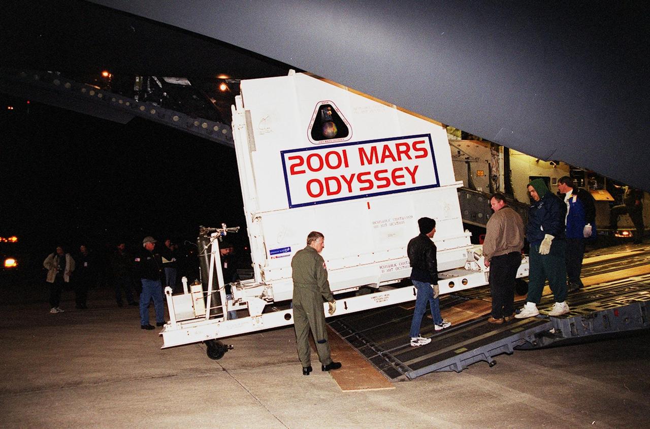
The Mars Odyssey spacecraft is removed from the Air Force C-17 cargo airplane that brought it from Denver, Colo.., location of the Lockheed Martin plant where the spacecraft was built. Mars Odyssey will be moved on a transport trailer from KSC’s Shuttle Landing Facility to the Spacecraft Assembly and Encapsulation Facility 2 (SAEF-2) located in the KSC Industrial Area. In the SAEF it will undergo final assembly and checkout. This includes installation of two of the three science instruments, integration of the three-panel solar array, and a spacecraft functional test. It will be fueled and then mated to an upper stage booster, the final activities before going to the launch pad. Launch is planned for April 7, 2001 the first day of a 21-day planetary window. Mars Odyssey will be inserted into an interplanetary trajectory by a Boeing Delta II launch vehicle from Pad A at Complex 17 at the Cape Canaveral Air Force Station, Fla. The spacecraft will arrive at Mars on Oct. 20, 2001, for insertion into an initial elliptical capture orbit. Its final operational altitude will be a 250-mile-high, Sun-synchronous polar orbit. Mars Odyssey will spend two years mapping the planet's surface and measuring its environment
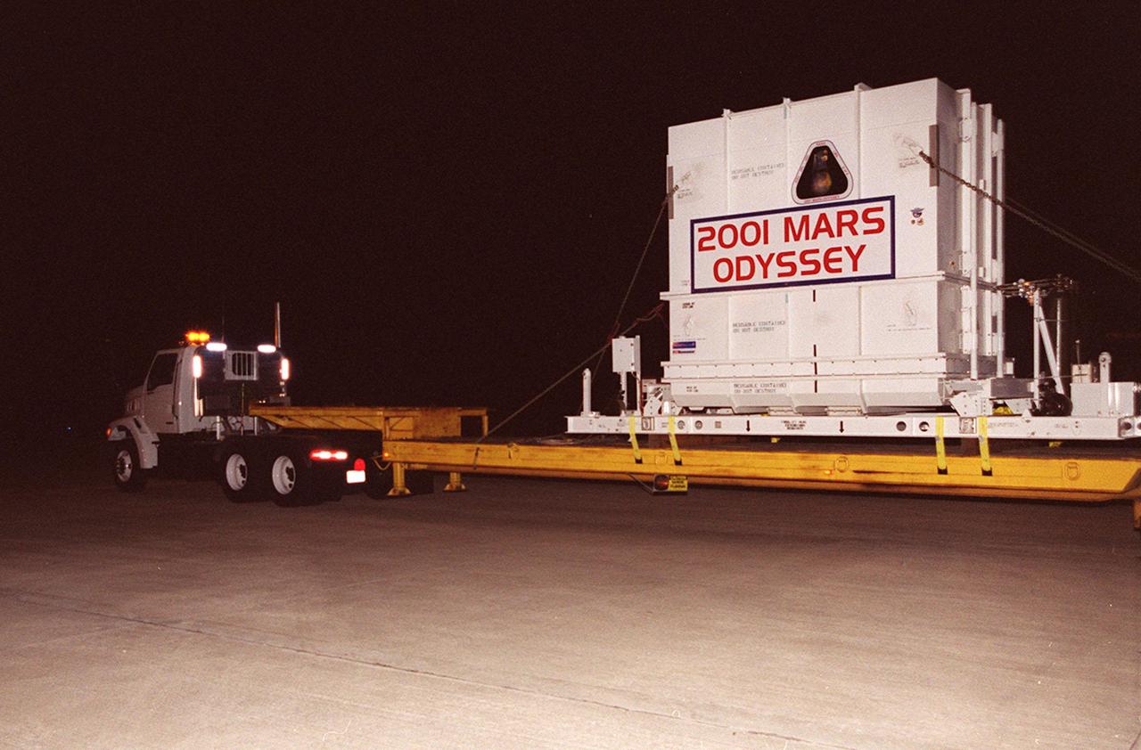
The 2001 Mars Odyssey spacecraft leaves the KSC Shuttle Landing Facility on the bed of a transport trailer. The spacecraft is being moved to the Spacecraft Assembly and Encapsulation Facility 2 (SAEF-2) located in the KSC Industrial Area. The spacecraft arrived at the SLF aboard an Air Force C-17 cargo airplane that brought it from Denver, Colo.., location of the Lockheed Martin plant where the spacecraft was built. In the SAEF, Odyssey will undergo final assembly and checkout. This includes installation of two of the three science instruments, integration of the three-panel solar array, and a spacecraft functional test. It will be fueled and then mated to an upper stage booster, the final activities before going to the launch pad. Launch is planned for April 7, 2001 the first day of a 21-day planetary window. Mars Odyssey will be inserted into an interplanetary trajectory by a Boeing Delta II launch vehicle from Pad A at Complex 17 at the Cape Canaveral Air Force Station, Fla. The spacecraft will arrive at Mars on Oct. 20, 2001, for insertion into an initial elliptical capture orbit. Its final operational altitude will be a 250-mile-high, Sun-synchronous polar orbit. Mars Odyssey will spend two years mapping the planet's surface and measuring its environment
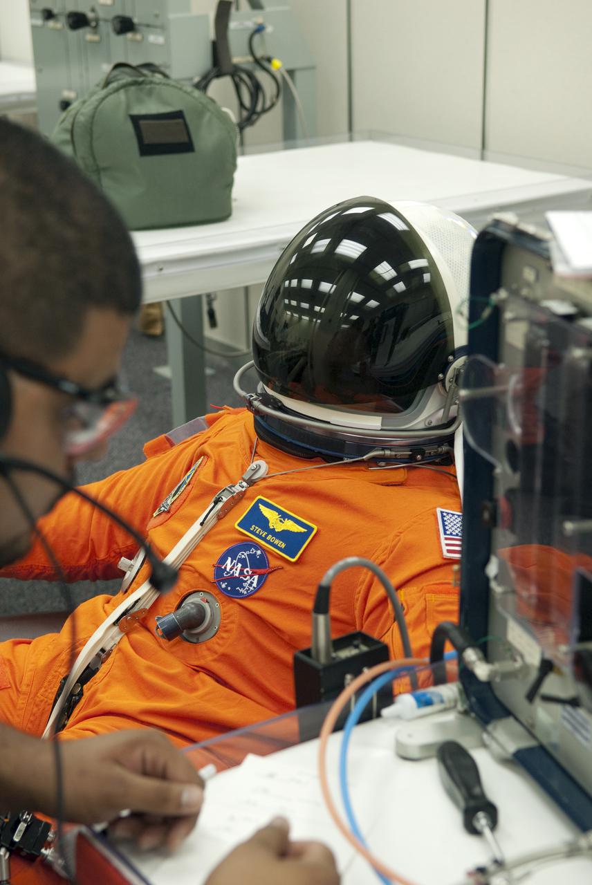
CAPE CANAVERAL, Fla. - In the Operations and Checkout Building at NASA's Kennedy Space Center in Florida, STS-132 Mission Specialist Steve Bowen verifies that his space suit's helmet is functioning properly. STS-132 is Bowen's second spaceflight. The six-member STS-132 crew is at Kennedy for their Terminal Countdown Demonstration Test, or TCDT, a dress rehearsal for launch. Following this practice 'suit-up,' the astronauts will ride in the Astrovan to Launch Pad 39A where they will participate in a simulated launch countdown from their seats inside space shuttle Atlantis. Launch is targeted for 2:19 p.m. EDT on May 14. On the STS-132 mission, the crew will deliver an Integrated Cargo Carrier, or ICC, and the Russian-built Mini-Research Module-1, or MRM-1, to the International Space Station. The ICC is an unpressurized flat bed pallet and keel yoke assembly used to support the transfer of exterior cargo from the shuttle to the space station. The MRM-1, known as Rassvet, is the second in a series of new pressurized components for Russia and will be permanently attached to the Earth-facing port of the Zarya control module. Rassvet, which translates to 'dawn,' will be used for cargo storage and provide an additional docking port to the station. STS-132 is the 34th mission to the station and the 132nd shuttle mission overall. For information on the STS-132 mission, visit http:__www.nasa.gov_mission_pages_shuttle_shuttlemissions_sts132_index.html. Photo credit: NASA_Cory Huston
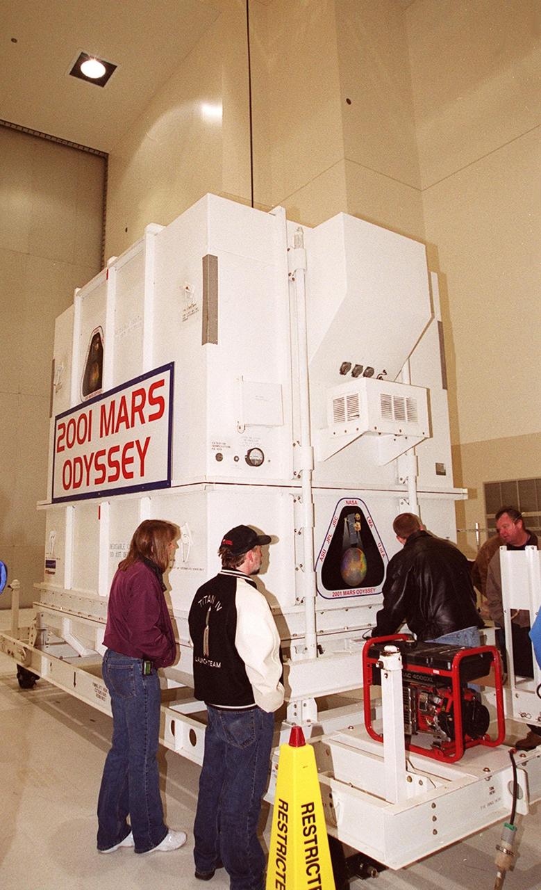
The crated 2001 Mars Odyssey spacecraft rests safely inside the Spacecraft Assembly and Encapsulation Facility 2 (SAEF-2) located in the KSC Industrial Area. The spacecraft arrived at KSC’s Shuttle Landing Facility aboard an Air Force C-17 cargo airplane that brought it from Denver, Colo.., location of the Lockheed Martin plant where the spacecraft was built. In the SAEF, Odyssey will undergo final assembly and checkout. This includes installation of two of the three science instruments, integration of the three-panel solar array, and a spacecraft functional test. It will be fueled and then mated to an upper stage booster, the final activities before going to the launch pad. Launch is planned for April 7, 2001 the first day of a 21-day planetary window. Mars Odyssey will be inserted into an interplanetary trajectory by a Boeing Delta II launch vehicle from Pad A at Complex 17 at the Cape Canaveral Air Force Station, Fla. The spacecraft will arrive at Mars on Oct. 20, 2001, for insertion into an initial elliptical capture orbit. Its final operational altitude will be a 250-mile-high, Sun-synchronous polar orbit. Mars Odyssey will spend two years mapping the planet's surface and measuring its environment

A forklift carries the crated Mars Odyssey spacecraft from the Air Force C-17 cargo airplane that brought it from Denver, Colo.., location of the Lockheed Martin plant where the spacecraft was built. The crate will placed on a transport trailer to take it from KSC’s Shuttle Landing Facility to the Spacecraft Assembly and Encapsulation Facility 2 (SAEF-2) located in the KSC Industrial Area. In the SAEF it will undergo final assembly and checkout. This includes installation of two of the three science instruments, integration of the three-panel solar array, and a spacecraft functional test. It will be fueled and then mated to an upper stage booster, the final activities before going to the launch pad. Launch is planned for April 7, 2001 the first day of a 21-day planetary window. Mars Odyssey will be inserted into an interplanetary trajectory by a Boeing Delta II launch vehicle from Pad A at Complex 17 at the Cape Canaveral Air Force Station, Fla. The spacecraft will arrive at Mars on Oct. 20, 2001, for insertion into an initial elliptical capture orbit. Its final operational altitude will be a 250-mile-high, Sun-synchronous polar orbit. Mars Odyssey will spend two years mapping the planet's surface and measuring its environment
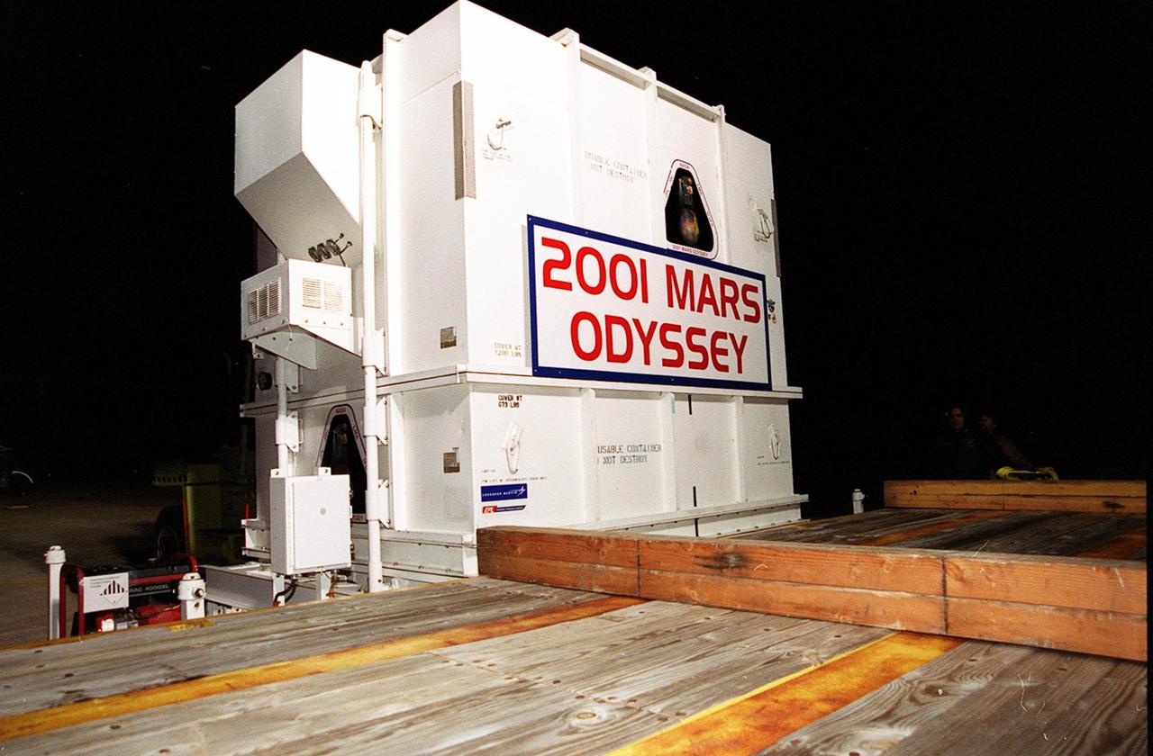
The 2001 Mars Odyssey spacecraft sits on the bed of the trailer that will take it from KSC’s Shuttle Landing Facility to the Spacecraft Assembly and Encapsulation Facility 2 (SAEF-2) located in the KSC Industrial Area. The spacecraft arrived at the SLF aboard an Air Force C-17 cargo airplane that brought it from Denver, Colo.., location of the Lockheed Martin plant where the spacecraft was built. In the SAEF Odyssey will undergo final assembly and checkout. This includes installation of two of the three science instruments, integration of the three-panel solar array, and a spacecraft functional test. It will be fueled and then mated to an upper stage booster, the final activities before going to the launch pad. Launch is planned for April 7, 2001 the first day of a 21-day planetary window. Mars Odyssey will be inserted into an interplanetary trajectory by a Boeing Delta II launch vehicle from Pad A at Complex 17 at the Cape Canaveral Air Force Station, Fla. The spacecraft will arrive at Mars on Oct. 20, 2001, for insertion into an initial elliptical capture orbit. Its final operational altitude will be a 250-mile-high, Sun-synchronous polar orbit. Mars Odyssey will spend two years mapping the planet's surface and measuring its environment
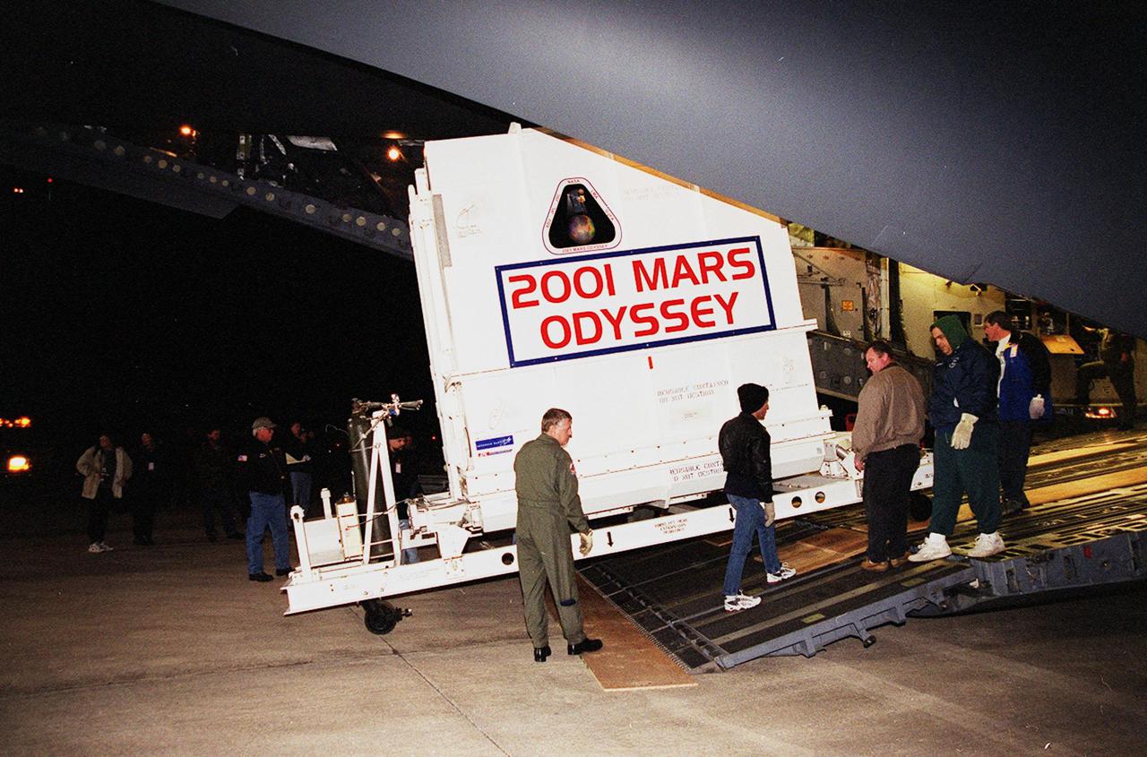
The Mars Odyssey spacecraft is removed from the Air Force C-17 cargo airplane that brought it from Denver, Colo.., location of the Lockheed Martin plant where the spacecraft was built. Mars Odyssey will be moved on a transport trailer from KSC’s Shuttle Landing Facility to the Spacecraft Assembly and Encapsulation Facility 2 (SAEF-2) located in the KSC Industrial Area. In the SAEF it will undergo final assembly and checkout. This includes installation of two of the three science instruments, integration of the three-panel solar array, and a spacecraft functional test. It will be fueled and then mated to an upper stage booster, the final activities before going to the launch pad. Launch is planned for April 7, 2001 the first day of a 21-day planetary window. Mars Odyssey will be inserted into an interplanetary trajectory by a Boeing Delta II launch vehicle from Pad A at Complex 17 at the Cape Canaveral Air Force Station, Fla. The spacecraft will arrive at Mars on Oct. 20, 2001, for insertion into an initial elliptical capture orbit. Its final operational altitude will be a 250-mile-high, Sun-synchronous polar orbit. Mars Odyssey will spend two years mapping the planet's surface and measuring its environment

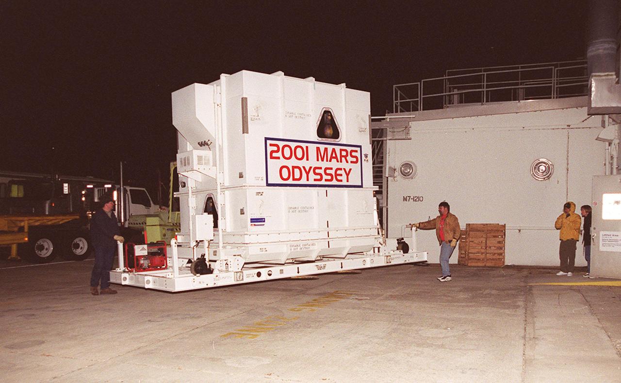
Workers push the crated 2001 Mars Odyssey spacecraft toward the Spacecraft Assembly and Encapsulation Facility 2 (SAEF-2) located in the KSC Industrial Area. The spacecraft arrived at KSC’s Shuttle Landing Facility aboard an Air Force C-17 cargo airplane that brought it from Denver, Colo.., location of the Lockheed Martin plant where the spacecraft was built. In the SAEF, Odyssey will undergo final assembly and checkout. This includes installation of two of the three science instruments, integration of the three-panel solar array, and a spacecraft functional test. It will be fueled and then mated to an upper stage booster, the final activities before going to the launch pad. Launch is planned for April 7, 2001 the first day of a 21-day planetary window. Mars Odyssey will be inserted into an interplanetary trajectory by a Boeing Delta II launch vehicle from Pad A at Complex 17 at the Cape Canaveral Air Force Station, Fla. The spacecraft will arrive at Mars on Oct. 20, 2001, for insertion into an initial elliptical capture orbit. Its final operational altitude will be a 250-mile-high, Sun-synchronous polar orbit. Mars Odyssey will spend two years mapping the planet's surface and measuring its environment
The 2001 Mars Odyssey spacecraft arrives at the Spacecraft Assembly and Encapsulation Facility 2 (SAEF-2) located in the KSC Industrial Area. The spacecraft arrived at KSC's Shuttle Landing Facility aboard an Air Force C-17 cargo airplane that brought it from Denver, Colo.., location of the Lockheed Martin plant where the spacecraft was built. In the SAEF, Odyssey will undergo final assembly and checkout. This includes installation of two of the three science instruments, integration of the three-panel solar array, and a spacecraft functional test. It will be fueled and then mated to an upper stage booster, the final activities before going to the launch pad. Launch is planned for April 7, 2001 the first day of a 21-day planetary window. Mars Odyssey will be inserted into an interplanetary trajectory by a Boeing Delta II launch vehicle from Pad A at Complex 17 at the Cape Canaveral Air Force Station, Fla. The spacecraft will arrive at Mars on Oct. 20, 2001, for insertion into an initial elliptical capture orbit. Its final operational altitude will be a 250-mile-high, Sun-synchronous polar orbit. Mars Odyssey will spend two years mapping the planet's surface and measuring its environment
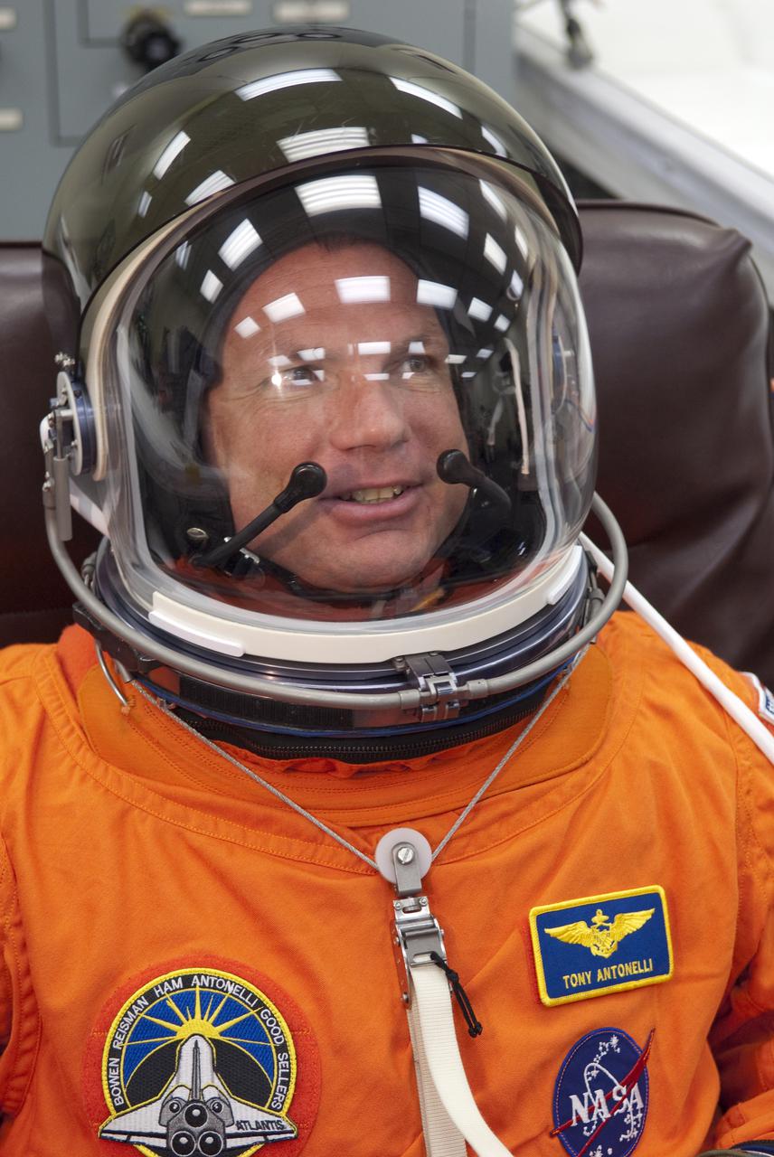
CAPE CANAVERAL, Fla. - In the Operations and Checkout Building at NASA's Kennedy Space Center in Florida, STS-132 Pilot Tony Antonelli verifies that his space suit's helmet is functioning properly. STS-132 is Antonelli's second spaceflight. The six-member STS-132 crew is at Kennedy for their Terminal Countdown Demonstration Test, or TCDT, a dress rehearsal for launch. Following this practice 'suit-up,' the astronauts will ride in the Astrovan to Launch Pad 39A where they will participate in a simulated launch countdown from their seats inside space shuttle Atlantis. Launch is targeted for 2:19 p.m. EDT on May 14. On the STS-132 mission, the crew will deliver an Integrated Cargo Carrier, or ICC, and the Russian-built Mini-Research Module-1, or MRM-1, to the International Space Station. The ICC is an unpressurized flat bed pallet and keel yoke assembly used to support the transfer of exterior cargo from the shuttle to the space station. The MRM-1, known as Rassvet, is the second in a series of new pressurized components for Russia and will be permanently attached to the Earth-facing port of the Zarya control module. Rassvet, which translates to 'dawn,' will be used for cargo storage and provide an additional docking port to the station. STS-132 is the 34th mission to the station and the 132nd shuttle mission overall. For information on the STS-132 mission, visit http:__www.nasa.gov_mission_pages_shuttle_shuttlemissions_sts132_index.html. Photo credit: NASA_Cory Huston
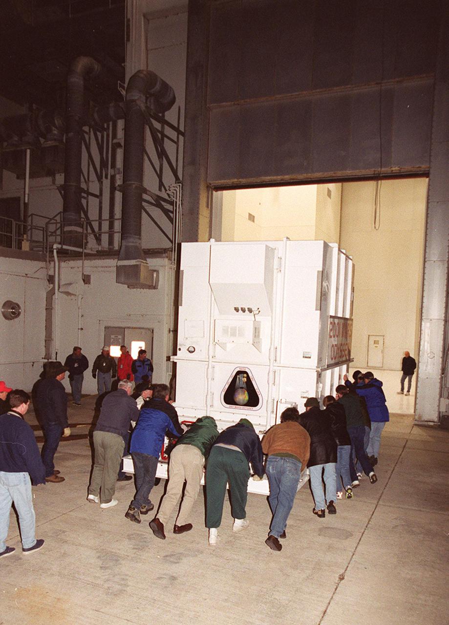
Workers push the crated 2001 Mars Odyssey spacecraft toward the Spacecraft Assembly and Encapsulation Facility 2 (SAEF-2) located in the KSC Industrial Area. The spacecraft arrived at KSC’s Shuttle Landing Facility aboard an Air Force C-17 cargo airplane that brought it from Denver, Colo.., location of the Lockheed Martin plant where the spacecraft was built. In the SAEF, Odyssey will undergo final assembly and checkout. This includes installation of two of the three science instruments, integration of the three-panel solar array, and a spacecraft functional test. It will be fueled and then mated to an upper stage booster, the final activities before going to the launch pad. Launch is planned for April 7, 2001 the first day of a 21-day planetary window. Mars Odyssey will be inserted into an interplanetary trajectory by a Boeing Delta II launch vehicle from Pad A at Complex 17 at the Cape Canaveral Air Force Station, Fla. The spacecraft will arrive at Mars on Oct. 20, 2001, for insertion into an initial elliptical capture orbit. Its final operational altitude will be a 250-mile-high, Sun-synchronous polar orbit. Mars Odyssey will spend two years mapping the planet's surface and measuring its environment
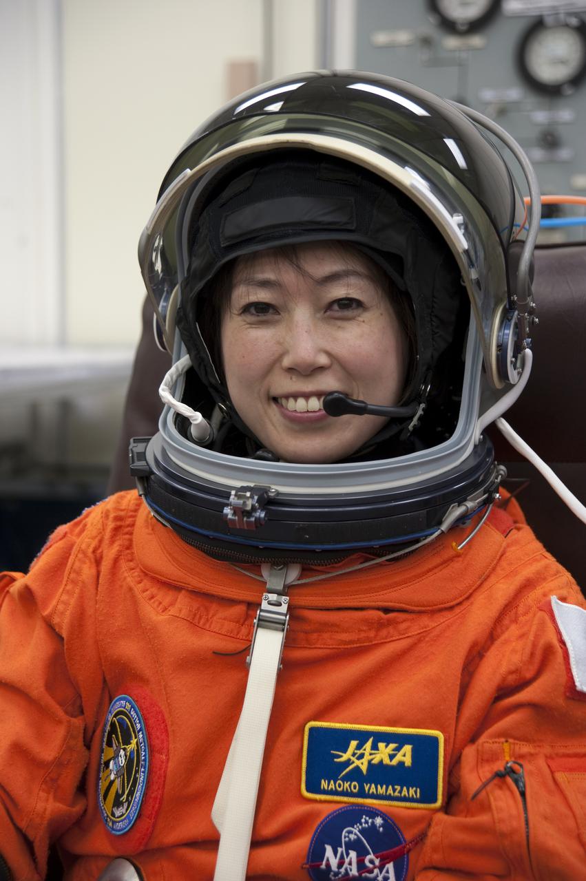
CAPE CANAVERAL, Fla. - In the Operations and Checkout Building at NASA's Kennedy Space Center in Florida, STS-131 Mission Specialist Naoko Yamazaki of the Japan Aerospace Exploration Agency verifies that her helmet is functioning properly. The members of space shuttle Discovery's STS-131 crew put on their launch-and-entry suits before heading to the Astrovan for the ride to Launch Pad 39A. The crew is participating in the Terminal Countdown Demonstration Test, or TCDT, a dress rehearsal for launch. TCDT includes training on the emergency egress systems at the launch pad, driving practice of the M-113 armored personnel carrier and a simulated launch countdown. The crew will deliver the multi-purpose logistics module Leonard, filled with resupply stowage platforms and science racks, to the International Space Station. STS-131, targeted for launch on April 5, will be the 33rd shuttle mission to the station and the 131st shuttle mission overall. For information on the STS-131 mission and crew, visit http:__www.nasa.gov_mission_pages_shuttle_shuttlemissions_sts131_index.htm. Photo credit: NASA_Kim Shiflett
CAPE CANAVERAL, Fla. -- At Launch Pad 39A at NASA's Kennedy Space Center in Florida, work is under way to close space shuttle Atlantis' payload bay doors around the Raffaello multi-purpose logistics module (MPLM) payload for Atlantis' STS-135 mission to the International Space Station. Seen here is the airlock which is sized to accommodate two fully suited flight crew members simultaneously. Support functions include airlock depressurization and repressurization, extravehicular activity equipment recharge, liquid-cooled garment water cooling, spacesuit equipment checkout, and communications. Commander Chris Ferguson, Pilot Doug Hurley and Mission Specialists Sandra Magnus and Rex Walheim are slated to lift off on July 8, taking with them the MPLM packed with supplies and spare parts to the station. The STS-135 mission also will fly a system to investigate the potential for robotically refueling existing satellites and return a failed ammonia pump module to help NASA better understand the failure mechanism and improve pump designs for future systems. STS-135 will be the 33rd flight of Atlantis, the 37th shuttle mission to the space station, and the 135th and final mission of NASA's Space Shuttle Program. For more information visit, www.nasa.gov/mission_pages/shuttle/shuttlemissions/sts135/index.html. Photo credit: NASA/Frank Michaux