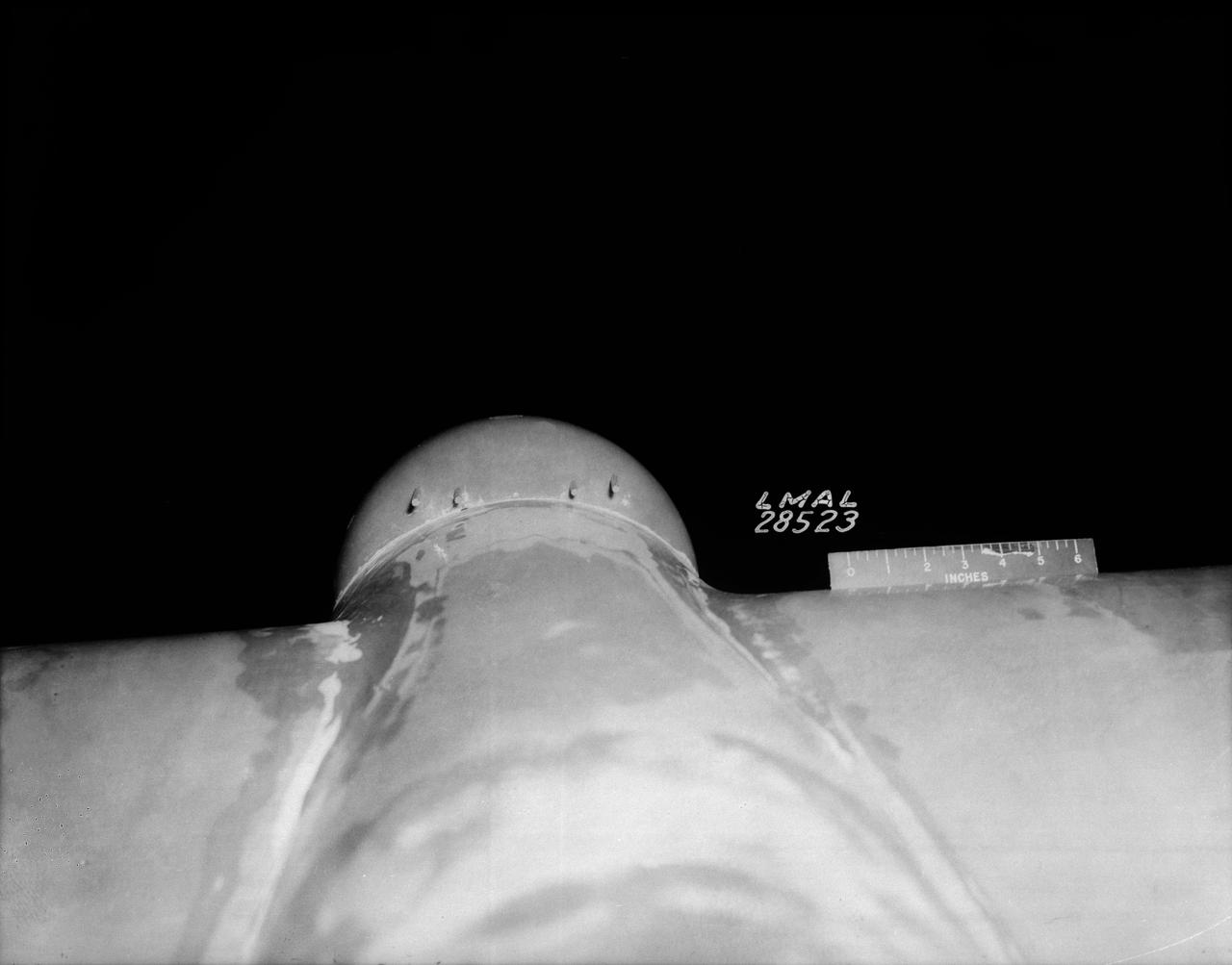
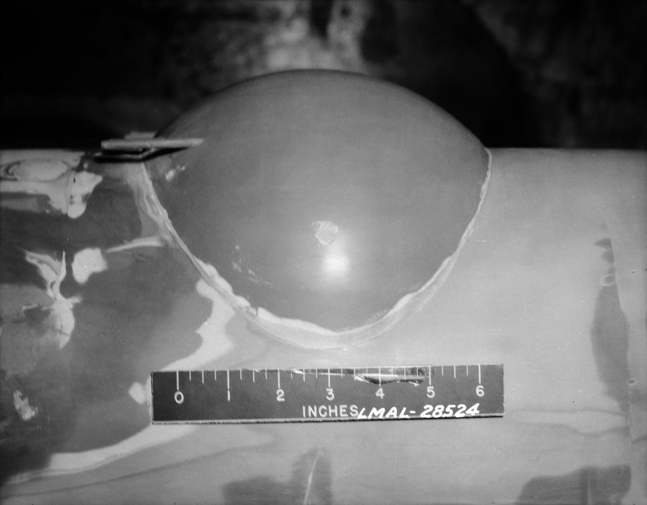
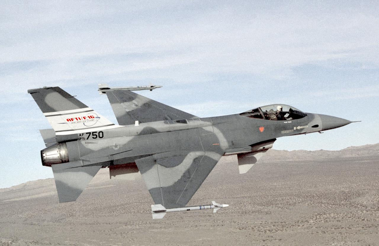
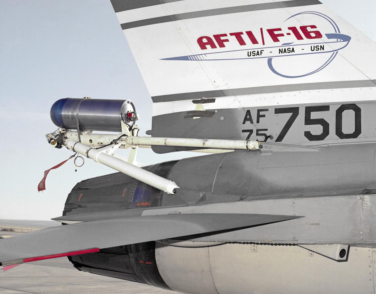
G.E fan-in-fuselage model (lifting) 3/4 front view of fan at low G.P. position
General Electric Fan-In-Fuselage Model in the 40x80 Foot Wind Tunnel at NASA Ames.
G.E. Fan-in-fuselage model (lifting). 3/4 front view of fan at low G.P. position.  Lift fan on variable height strut for ground effects studies. T-Tail
General Electric Fan-In-Fuselage model in the 40x80 Foot Wind Tunnel at NASA Ames.
G.E. Fan-in-fuselage model (lifting). 3/4 rear view of fan at low G.P. position.  Lift fan on variable height strut for ground effects studies with reaction control. T-Tail.
General Electric Fan-In-Fuselage Lifting Model in the 40x80 Foot Wind Tunnel at NASA Ames.
The Italian Tecnam aircraft fuselage, P2006T, arrived in California and will be integrated with the wing for electric propulsion becoming X-57, or Maxwell.
X-57 Aircraft Fuselage Arrives in California
Preparations are underway to inspect, weigh and balance the Tecnam fuselage before it heads to Mojave, California, for wing integration.
X-57 Aircraft Fuselage Arrives in California
Technicians are shown here working on the X-59 fuselage section of the aircraft. The fuselage contains the cockpit and helps define the distinct shape of the X-59.  Lockheed Martin Photography By Garry Tice 1011 Lockheed Way, Palmdale, Ca. 93599 Event: SEG 210 Forebody-Subsystems Date: 5/12/2021
SEG 210 Forebody-Subsystems
Technicians are shown here working on the X-59 fuselage section of the aircraft.  The fuselage contains the cockpit and helps define the distinct shape of the X-59.  Lockheed Martin Photography By Garry Tice 1011 Lockheed Way, Palmdale, Ca. 93599 Event: SEG 210 Forebody-Subsystems Date: 5/12/2021
SEG 210 Forebody-Subsystems
Here is a closer view of the X-59 fuselage section of the aircraft during assembly. The fuselage contains the cockpit and helps define the distinct shape of the X-59.  Lockheed Martin Photography By Garry Tice 1011 Lockheed Way, Palmdale, Ca. 93599 Event: SEG 210 Forebody-Subsystems Date: 5/12/2021
SEG 210 Forebody-Subsystems
3/4 Low front view of fuselage and fan. Showing jet engine hanging below. Lift fan powered by jet exhaust. General Aerodynamic Characteristics of a Research Model with High Disk Loading Direct Lifting Fan Mounted in Fuselage
General Aerodynamic Characteristics of a Research Model with High Disk Loading Direct Lifting Fan Mounted in Fuselage
3/4 Low front view of fuselage and fan. Showing jet engine hanging below. Lift fan powered by jet exhaust.
AC-27149-A. General Aerodynamic Characteristics of a Research Model with High Disk Loading Direct Lifting Fan Mounted in Fuselage.
A Lockheed Martin technician prepares holes for installation of the fuselage panel on the X-59. The fuselage is the section of the aircraft that contains the cockpit. The aircraft, under construction at Lockheed Martin Skunk Works in Palmdale, California, will demonstrate the ability to fly supersonic while reducing the loud sonic boom to a quiet sonic thump.
LRC-2022-H1_P_X-59-8
STS 51-E crew is briefed on the Shuttle full fuselage trainer. View of the crewmembers seated at stations inside the cabin was taken from the side hatch.
STS 51-E crew is briefed on the Shuttle full fuselage trainer
The one-third scale twin-fuselage towed glider glides in for landing on Rogers Dry Lake after its successful first test flight.
Towed Twin-Fuselage Glider Launch System First Test Flight
STS 51-E crew is briefed on the Shuttle full fuselage trainer. Astronauts Dave Griggs (foreground), Jean Loup Chretien (behind Griggs) and Jeff Hoffman are being shown the workings of the trainer by flight instructors.
STS 51-E crew is briefed on the Shuttle full fuselage trainer
Curved Confocal Lightweight Antenna Structures for Aeronautical Communications Technologies, CLAS-ACT, Phased Array Antenna on Mock Carbon Fiber Fuselage
Curved Confocal Lightweight Antenna Structures for Aeronautic...
Curved Confocal Lightweight Antenna Structures for Aeronautical Communications Technologies, CLAS-ACT, Phased Array Antenna on Mock Carbon Fiber Fuselage
Curved Confocal Lightweight Antenna Structures for Aeronautic...
Curved Confocal Lightweight Antenna Structures for Aeronautical Communications Technologies, CLAS-ACT, Phased Array Antenna on Mock Carbon Fiber Fuselage
Curved Confocal Lightweight Antenna Structures for Aeronautic...
B-33 Vega Turrets.  Photo are listed in the NACA Wartime report L-463, October 1942, Test of a Large Spherical Turret and a modified Turret on a Typical Bomber Fuselage by Axel T. Mattson.
B-33 Vega Turrets
B-33 Vega Turrets.  Photo are listed in the NACA Wartime report L-463, October 1942, Test of a Large Spherical Turret and a modified Turret on a Typical Bomber Fuselage by Axel T. Mattson.
B-33 Vega Turrets
A number of atmospheric probes are installed along the fuselage of NASA's DC-8 in preparation for the SEAC4RS study to learn more about how air pollution and natural emissions affect climate change.
ED13-0225-050
The German-built 100-inch telescope that is the heart of NASA's Stratospheric Observatory for Infrared Astronomy is nestled in the SOFIA 747's rear fuselage.
The German-built 100-inch telescope that is the heart of NASA's Stratospheric Observatory for Infrared Astronomy is nestled in the SOFIA 747's rear fuselage
The SOFIA airborne observatory's 2.5-meter infrared telescope peers out from its cavity in the SOFIA rear fuselage during nighttime line operations testing.
The SOFIA airborne observatory's 2.5-meter infrared telescope peers out from its cavity in the SOFIA rear fuselage during nighttime line operations testing
A rotating external door (white) was installed over the telescope cavity in the rear fuselage of NASA's SOFIA Boeing 747SP during modifications in Waco, Texas.
A rotating external door (white) was installed over the telescope cavity in the rear fuselage of NASA's SOFIA Boeing 747SP during modifications in Waco, Texas
Event: SEG 210 Forebody A Lockheed Martin technician prepares to install the left fuselage skins onto the X-59. Once in the air, the aircraft, currently under construction at Lockheed Martin Skunk Works in Palmdale, California, will demonstrate the ability to fly supersonic while reducing the loud sonic boom to a quiet sonic thump.
SEG 210 Forebody
Lockheed Martin technicians work to align and check the fastener holes on the X-59’s fuselage skin. The aircraft, under construction at Lockheed Martin Skunk Works in Palmdale, California, will demonstrate the ability to fly supersonic while reducing the loud sonic boom to a quiet sonic thump.
LRC-2022-H1_P_X-59-6
An inert AIM-54 Phoenix missile nestled under the fuselage of NASA Dryden's F-15B aircraft is being studied as a possible test vehicle to obtain hypersonic data.
An inert Phoenix missile nestled under the fuselage of NASA Dryden's F-15B aircraft is being studied as a possible test vehicle to obtain hypersonic data.
JSC2010-E-046401 (31 March 2010) --- Attired in a training version of her shuttle launch and entry suit, NASA astronaut Nicole Stott, STS-133 mission specialist, participates in a Full Fuselage Trainer (FFT) mock-up training session in the Space Vehicle Mockup Facility at NASA's Johnson Space Center.
STS-133 crew during Payload Egress training in Full Fuselage Trainer (FFT)
JSC2010-E-046399 (31 March 2010) --- Attired in a training version of his shuttle launch and entry suit, NASA astronaut Tim Kopra, STS-133 mission specialist, participates in a Full Fuselage Trainer (FFT) mock-up training session in the Space Vehicle Mock-up Facility at NASA's Johnson Space Center.
STS-133 crew during Payload Egress training in Full Fuselage Trainer (FFT)
JSC2010-E-046409 (31 March 2010) --- Attired in a training version of his shuttle launch and entry suit, NASA astronaut Steve Lindsey, STS-133 commander, participates in a Full Fuselage Trainer (FFT) mock-up training session in the Space Vehicle Mockup Facility at NASA's Johnson Space Center.
STS-133 crew during Payload Egress training in Full Fuselage Trainer (FFT)
he SOFIA airborne observatory's 2.5-meter infrared telescope peers out from its cavity in the SOFIA rear fuselage during nighttime line operations testing.
he SOFIA airborne observatory's 2.5-meter infrared telescope peers out from its cavity in the SOFIA rear fuselage during nighttime line operations testing
NASA's SOFIA 747SP shows evidence of modification to its aft fuselage contours to accommodate a 16-foot-tall cavity door for its 45,000-pound infrared telescope.
NASA's SOFIA 747SP shows evidence of modification to its aft fuselage contours to accommodate a 16-foot-tall cavity door for its 45,000-pound infrared telescope
Event: SEG 210 Forebody A right side view of where the team is preparing the X-59 structure for installation of the forward fuselage, which contains the cockpit. The aircraft, under construction at Lockheed Martin Skunk Works in Palmdale, California, will fly to demonstrate the ability to fly supersonic while reducing the loud sonic boom to a quiet sonic thump.
SEG 210 Forebody
JSC2010-E-046408 (31 March 2010) --- Attired in training versions of their shuttle launch and entry suits, the STS-133 crew members await the start of a Full Fuselage Trainer (FFT) mock-up training session in the Space Vehicle Mockup Facility at NASA's Johnson Space Center. Pictured from the right are NASA astronauts Steve Lindsey, commander; Michael Barratt, Tim Kopra, Nicole Stott, all mission specialists; Eric Boe (mostly obscured), pilot; and Alvin Drew, mission specialist.
STS-133 crew during Payload Egress training in Full Fuselage Trainer (FFT)
This photo depicts the AFTI F-16 in the configuration used midway through the program. The sensor pods were added to the fuselage, but the chin canards remained in place. Painted in non-standard gray tones, it carried Sidewinder air-to-air missles on its wingtips.
EC89-0016-20
KENNEDY SPACE CENTER, FLA. - In the Orbiter Processing Facility, one of two orbital maneuvering system (OMS) pods is being moved for installation on Atlantis.  The OMS pods are attached to the upper aft fuselage left and right sides. Fabricated primarily of graphite epoxy composite and aluminum, each pod is 21.8 feet long and 11.37 feet wide at its aft end and 8.41 feet wide at its forward end, with a surface area of approximately 435 square feet. Each pod houses the Reaction Control System propulsion components used for inflight maneuvering and is attached to the aft fuselage with 11 bolts.
KENNEDY SPACE CENTER, FLA. - In the Orbiter Processing Facility, one of two orbital maneuvering system (OMS) pods is being moved for installation on Atlantis. The OMS pods are attached to the upper aft fuselage left and right sides. Fabricated primarily of graphite epoxy composite and aluminum, each pod is 21.8 feet long and 11.37 feet wide at its aft end and 8.41 feet wide at its forward end, with a surface area of approximately 435 square feet. Each pod houses the Reaction Control System propulsion components used for inflight maneuvering and is attached to the aft fuselage with 11 bolts.
KENNEDY SPACE CENTER, FLA. - In the Orbiter Processing Facility, technicians move an orbital maneuvering system (OMS) pod into the correct position on Atlantis. The OMS pod is one of two that are attached to the upper aft fuselage left and right sides. Fabricated primarily of graphite epoxy composite and aluminum, each pod is 21.8 feet long and 11.37 feet wide at its aft end and 8.41 feet wide at its forward end, with a surface area of approximately 435 square feet. Each pod houses the Reaction Control System propulsion components used for inflight maneuvering and is attached to the aft fuselage with 11 bolts.
KENNEDY SPACE CENTER, FLA. - In the Orbiter Processing Facility, an orbital maneuvering system (OMS) pod is moved into place on Atlantis.  It is one of two OMS pods attached to the upper aft fuselage left and right sides. Fabricated primarily of graphite epoxy composite and aluminum, each pod is 21.8 feet long and 11.37 feet wide at its aft end and 8.41 feet wide at its forward end, with a surface area of approximately 435 square feet. Each pod houses the Reaction Control System propulsion components used for inflight maneuvering and is attached to the aft fuselage with 11 bolts.
KENNEDY SPACE CENTER, FLA. - In the Orbiter Processing Facility, an orbital maneuvering system (OMS) pod is moved into place on Atlantis. It is one of two OMS pods attached to the upper aft fuselage left and right sides. Fabricated primarily of graphite epoxy composite and aluminum, each pod is 21.8 feet long and 11.37 feet wide at its aft end and 8.41 feet wide at its forward end, with a surface area of approximately 435 square feet. Each pod houses the Reaction Control System propulsion components used for inflight maneuvering and is attached to the aft fuselage with 11 bolts.
KENNEDY SPACE CENTER, FLA. - In the Orbiter Processing Facility, workers discuss the next step in moving the orbital maneuvering system (OMS) pod behind them.  The OMS pod will be installed on Atlantis.  Two OMS pods are attached to the upper aft fuselage left and right sides. Fabricated primarily of graphite epoxy composite and aluminum, each pod is 21.8 feet long and 11.37 feet wide at its aft end and 8.41 feet wide at its forward end, with a surface area of approximately 435 square feet. Each pod houses the Reaction Control System propulsion components used for inflight maneuvering and is attached to the aft fuselage with 11 bolts.
KENNEDY SPACE CENTER, FLA. - In the Orbiter Processing Facility, workers discuss the next step in moving the orbital maneuvering system (OMS) pod behind them. The OMS pod will be installed on Atlantis. Two OMS pods are attached to the upper aft fuselage left and right sides. Fabricated primarily of graphite epoxy composite and aluminum, each pod is 21.8 feet long and 11.37 feet wide at its aft end and 8.41 feet wide at its forward end, with a surface area of approximately 435 square feet. Each pod houses the Reaction Control System propulsion components used for inflight maneuvering and is attached to the aft fuselage with 11 bolts.
KENNEDY SPACE CENTER, FLA. -  In the Orbiter Processing Facility, one of two orbital maneuvering system (OMS) pods is lifted off its stand to move it toward Atlantis for installation. The OMS pods are attached to the upper aft fuselage left and right sides. Fabricated primarily of graphite epoxy composite and aluminum, each pod is 21.8 feet long and 11.37 feet wide at its aft end and 8.41 feet wide at its forward end, with a surface area of approximately 435 square feet. Each pod houses the Reaction Control System propulsion components used for inflight maneuvering and is attached to the aft fuselage with 11 bolts.
KENNEDY SPACE CENTER, FLA. - In the Orbiter Processing Facility, one of two orbital maneuvering system (OMS) pods is lifted off its stand to move it toward Atlantis for installation. The OMS pods are attached to the upper aft fuselage left and right sides. Fabricated primarily of graphite epoxy composite and aluminum, each pod is 21.8 feet long and 11.37 feet wide at its aft end and 8.41 feet wide at its forward end, with a surface area of approximately 435 square feet. Each pod houses the Reaction Control System propulsion components used for inflight maneuvering and is attached to the aft fuselage with 11 bolts.
KENNEDY SPACE CENTER, FLA. - In the Orbiter Processing Facility, technicians make final adjustments to the orbital maneuvering system (OMS) pod being installed on Atlantis.   The OMS pod is one of two that are attached to the upper aft fuselage left and right sides. Fabricated primarily of graphite epoxy composite and aluminum, each pod is 21.8 feet long and 11.37 feet wide at its aft end and 8.41 feet wide at its forward end, with a surface area of approximately 435 square feet. Each pod houses the Reaction Control System propulsion components used for inflight maneuvering and is attached to the aft fuselage with 11 bolts.
KENNEDY SPACE CENTER, FLA. - In the Orbiter Processing Facility, technicians make final adjustments to the orbital maneuvering system (OMS) pod being installed on Atlantis. The OMS pod is one of two that are attached to the upper aft fuselage left and right sides. Fabricated primarily of graphite epoxy composite and aluminum, each pod is 21.8 feet long and 11.37 feet wide at its aft end and 8.41 feet wide at its forward end, with a surface area of approximately 435 square feet. Each pod houses the Reaction Control System propulsion components used for inflight maneuvering and is attached to the aft fuselage with 11 bolts.
KENNEDY SPACE CENTER, FLA. - In the Orbiter Processing Facility, one of two orbital maneuvering system (OMS) pods is being moved for installation on Atlantis.  The OMS pods are attached to the upper aft fuselage left and right sides. Fabricated primarily of graphite epoxy composite and aluminum, each pod is 21.8 feet long and 11.37 feet wide at its aft end and 8.41 feet wide at its forward end, with a surface area of approximately 435 square feet. Each pod houses the Reaction Control System propulsion components used for inflight maneuvering and is attached to the aft fuselage with 11 bolts.
KENNEDY SPACE CENTER, FLA. - In the Orbiter Processing Facility, one of two orbital maneuvering system (OMS) pods is being moved for installation on Atlantis. The OMS pods are attached to the upper aft fuselage left and right sides. Fabricated primarily of graphite epoxy composite and aluminum, each pod is 21.8 feet long and 11.37 feet wide at its aft end and 8.41 feet wide at its forward end, with a surface area of approximately 435 square feet. Each pod houses the Reaction Control System propulsion components used for inflight maneuvering and is attached to the aft fuselage with 11 bolts.
KENNEDY SPACE CENTER, FLA. - In the Orbiter Processing Facility, technicians make adjustments to the orbital maneuvering system (OMS) pod being installed on Atlantis.   The OMS pod is one of two that are attached to the upper aft fuselage left and right sides. Fabricated primarily of graphite epoxy composite and aluminum, each pod is 21.8 feet long and 11.37 feet wide at its aft end and 8.41 feet wide at its forward end, with a surface area of approximately 435 square feet. Each pod houses the Reaction Control System propulsion components used for inflight maneuvering and is attached to the aft fuselage with 11 bolts.
KENNEDY SPACE CENTER, FLA. - In the Orbiter Processing Facility, technicians make adjustments to the orbital maneuvering system (OMS) pod being installed on Atlantis. The OMS pod is one of two that are attached to the upper aft fuselage left and right sides. Fabricated primarily of graphite epoxy composite and aluminum, each pod is 21.8 feet long and 11.37 feet wide at its aft end and 8.41 feet wide at its forward end, with a surface area of approximately 435 square feet. Each pod houses the Reaction Control System propulsion components used for inflight maneuvering and is attached to the aft fuselage with 11 bolts.
KENNEDY SPACE CENTER, FLA. -  In the Orbiter Processing Facility, an orbital maneuvering system (OMS) pod is moved closer to Atlantis for installation.  Two OMS pods are attached to the upper aft fuselage left and right sides. Fabricated primarily of graphite epoxy composite and aluminum, each pod is 21.8 feet long and 11.37 feet wide at its aft end and 8.41 feet wide at its forward end, with a surface area of approximately 435 square feet. Each pod houses the Reaction Control System propulsion components used for inflight maneuvering and is attached to the aft fuselage with 11 bolts.
KENNEDY SPACE CENTER, FLA. - In the Orbiter Processing Facility, an orbital maneuvering system (OMS) pod is moved closer to Atlantis for installation. Two OMS pods are attached to the upper aft fuselage left and right sides. Fabricated primarily of graphite epoxy composite and aluminum, each pod is 21.8 feet long and 11.37 feet wide at its aft end and 8.41 feet wide at its forward end, with a surface area of approximately 435 square feet. Each pod houses the Reaction Control System propulsion components used for inflight maneuvering and is attached to the aft fuselage with 11 bolts.
KENNEDY SPACE CENTER, FLA. -  In the Orbiter Processing Facility, an orbital maneuvering system (OMS) pod is suspended in air as it is moved toward Atlantis for installation.  Two OMS pods are attached to the upper aft fuselage left and right sides. Fabricated primarily of graphite epoxy composite and aluminum, each pod is 21.8 feet long and 11.37 feet wide at its aft end and 8.41 feet wide at its forward end, with a surface area of approximately 435 square feet. Each pod houses the Reaction Control System propulsion components used for inflight maneuvering and is attached to the aft fuselage with 11 bolts.
KENNEDY SPACE CENTER, FLA. - In the Orbiter Processing Facility, an orbital maneuvering system (OMS) pod is suspended in air as it is moved toward Atlantis for installation. Two OMS pods are attached to the upper aft fuselage left and right sides. Fabricated primarily of graphite epoxy composite and aluminum, each pod is 21.8 feet long and 11.37 feet wide at its aft end and 8.41 feet wide at its forward end, with a surface area of approximately 435 square feet. Each pod houses the Reaction Control System propulsion components used for inflight maneuvering and is attached to the aft fuselage with 11 bolts.
KENNEDY SPACE CENTER, FLA. -  In the Orbiter Processing Facility, technicians move an orbital maneuvering system (OMS) pod into the correct position on Atlantis. The OMS pod is one of two that are attached to the upper aft fuselage left and right sides. Fabricated primarily of graphite epoxy composite and aluminum, each pod is 21.8 feet long and 11.37 feet wide at its aft end and 8.41 feet wide at its forward end, with a surface area of approximately 435 square feet. Each pod houses the Reaction Control System propulsion components used for inflight maneuvering and is attached to the aft fuselage with 11 bolts.
KENNEDY SPACE CENTER, FLA. - In the Orbiter Processing Facility, technicians move an orbital maneuvering system (OMS) pod into the correct position on Atlantis. The OMS pod is one of two that are attached to the upper aft fuselage left and right sides. Fabricated primarily of graphite epoxy composite and aluminum, each pod is 21.8 feet long and 11.37 feet wide at its aft end and 8.41 feet wide at its forward end, with a surface area of approximately 435 square feet. Each pod houses the Reaction Control System propulsion components used for inflight maneuvering and is attached to the aft fuselage with 11 bolts.
KENNEDY SPACE CENTER, FLA. - In the Orbiter Processing Facility, an orbital maneuvering system (OMS) pod is moved into place on Atlantis.  It is one of two OMS pods attached to the upper aft fuselage left and right sides. Fabricated primarily of graphite epoxy composite and aluminum, each pod is 21.8 feet long and 11.37 feet wide at its aft end and 8.41 feet wide at its forward end, with a surface area of approximately 435 square feet. Each pod houses the Reaction Control System propulsion components used for inflight maneuvering and is attached to the aft fuselage with 11 bolts.
KENNEDY SPACE CENTER, FLA. - In the Orbiter Processing Facility, an orbital maneuvering system (OMS) pod is moved into place on Atlantis. It is one of two OMS pods attached to the upper aft fuselage left and right sides. Fabricated primarily of graphite epoxy composite and aluminum, each pod is 21.8 feet long and 11.37 feet wide at its aft end and 8.41 feet wide at its forward end, with a surface area of approximately 435 square feet. Each pod houses the Reaction Control System propulsion components used for inflight maneuvering and is attached to the aft fuselage with 11 bolts.
NASA’s DC-8 aircraft at Carlos Ibanez International Airport in Punta Arenas, Chile. A portion of AirSAR hardware is visible on the left rear fuselage. AirSAR 2004 is a three-week expedition in Central and South America by an international team of scientists that is using an all-weather imaging tool, called the Airborne Synthetic Aperture Radar (AirSAR), located onboard NASA's DC-8 airborne laboratory. Scientists from many parts of the world are combining ground research with NASA's AirSAR technology to improve and expand on the quality of research they are able to conduct.
NASA’s DC-8 aircraft at Carlos Ibanez International Airport in Punta Arenas, Chile. A portion of AirSAR hardware is visible on the left rear fuselage
NASA's all-electric X-57 Maxwell had its Mod II wing carefully prepared for a lift to position it over the fuselage for reattachment at NASA's Armstrong Flight Research Center in California. The aircraft was shipped as two parts, the fuselage and the wing.
X-57 Mod II Reassembly Begins at NASA Armstrong
Lockheed P-38 model. Underslung elongated fuselage with tail.
ARC-1942-AAL-2125
R.T. Jones Oblique Wing model:  singal fuselage - 3 view artwork
ARC-1972-A72-1960
R.T. JONES OBLIQUE WING TRANSONIC TRANSPORT MODEL  2-BODY 'DOUBLE' FUSELAGE
ARC-1970-A70-5471
R.T. JONES OBLIQUE WING TRANSONIC TRANSPORT MODEL  2-BODY 'DOUBLE' FUSELAGE
ARC-1970-A70-5469
This photograph shows a ground cold flow test of the linear aerospike rocket engine mounted on the rear fuselage of an SR-71.
Linear Aerospike SR-71 Experiment (LASRE) ground cold flow test
The bulging fairing atop the forward fuselage of NASA's Ikhana unmanned aircraft covers a variety of navigation, communications and science instruments.
ED07-0038-029
In this photo of the C-140 JetStar on the Dryden Ramp, a subscale propeller has been fitted to the upper fuselage of the aircraft.
ECN-20293
OBLIQUE WING TRANSONIC TRANSPORT MODEL (2-BODY FUSELAGE) DR. R.T. JONES' CONCEPT
ARC-1971-A71-5604
Members of NASA's Mars Helicopter team attach a thermal film enclosure to the fuselage of the flight model (the actual vehicle going to the Red Planet). The image was taken on Feb. 1, 2019, inside the Space Simulator, a 25-foot-wide (7.62-meter-wide) vacuum chamber at NASA's Jet Propulsion Laboratory in Pasadena, California.  https://photojournal.jpl.nasa.gov/catalog/PIA23157
Composing Mars Helicopter
A close-up photo of the spin chute mounted on the rear fuselage of the AFTI F-16, a safety device designed to prevent the loss of aircraft in spin conditions. Under some circumstances, pilots cannot recover from spins using normal controls. It these instances, the spin chute is deployed, thus "breaking" the spin and enabling the pilot to recover. The spin chute is held in a metal cylinder attached to the AFTI F-16 by four tubes, a structure strong enough to withstand the shock of the spin chute opening. Unlike the air probe in the last photo, spin chutes are not standard equipment on research or prototype aircraft but are commonly attached expressly for actual spin tests.
ECN-22193
The above-the-fuselage engine and V-tail distinguish one of NASA's two Global Hawk unmanned aircraft parked on the ramp at the Dryden Flight Research Center.
ED07-0244-058
The tail section of the modified C-141 Kuiper Airborne Observatory, (KAO) (NASA-714), severed from the fuselage on the N211 apron of Moffett Field, California.
Kuiper Airborne Observatory (KAO) Demolition
The tail section of the modified C-141 Kuiper Airborne Observatory, (KAO) (NASA-714), severed from the fuselage on the N211 apron of Moffett Field, California.
Kuiper Airborne Observatory (KAO) Demolition
Engineers Raquel Rodriguez Monje and Fabien Nicaise discuss placement of the DopplerScatt radar instrument on the NASA B200 before its final installation onto the aircraft’s fuselage.
NASA Engineers Install DopplerScatt Instrument
The narrow fuselage of NASA'S Ikhana unmanned science aircraft, a civil version of General Atomics' Predator B, is evident in this view from underneath.
ED07-0038-092
The tail section of the modified C-141 Kuiper Airborne Observatory, (KAO) (NASA-714), severed from the fuselage on the N211 apron of Moffett Field, California.
Kuiper Airborne Observatory (KAO) Demolition
The tail section of the modified C-141 Kuiper Airborne Observatory, (KAO) (NASA-714), severed from the fuselage on the N211 apron of Moffett Field, California.
Kuiper Airborne Observatory (KAO) Demolition
ARTWORK BY RICK GUIDICE OBLIQUE WING TRANSONIC TRANSPORT MODEL:  DR ROBERT T JONES 2-BODY 'DOUBLE' FUSELAGE CONCEPT IN FLIGHT
ARC-1971-A71-5593
KENNEDY SPACE CENTER, FLA. -   Technicians in the Orbiter Processing Facility oversee removal of one of two orbital maneuvering system (OMS) pods from Endeavour.  The OMS pods are attached to the upper aft fuselage left and right sides.  Fabricated primarily of graphite epoxy composite and aluminum, each pod is 21.8 feet long and 11.37 feet wide at its aft end and 8.41 feet wide at its forward end, with a surface area of approximately 435 square feet.  Each pod houses the Reaction Control System propulsion components used for inflight maneuvering and is attached to the aft fuselage with 11 bolts.   OMS pods are removed during Orbiter Major Modifications. Once removed, the OMS pods undergo in-depth structural inspections, system checks and the thrusters are changed out.
KENNEDY SPACE CENTER, FLA. - Technicians in the Orbiter Processing Facility oversee removal of one of two orbital maneuvering system (OMS) pods from Endeavour. The OMS pods are attached to the upper aft fuselage left and right sides. Fabricated primarily of graphite epoxy composite and aluminum, each pod is 21.8 feet long and 11.37 feet wide at its aft end and 8.41 feet wide at its forward end, with a surface area of approximately 435 square feet. Each pod houses the Reaction Control System propulsion components used for inflight maneuvering and is attached to the aft fuselage with 11 bolts. OMS pods are removed during Orbiter Major Modifications. Once removed, the OMS pods undergo in-depth structural inspections, system checks and the thrusters are changed out.
KENNEDY SPACE CENTER, FLA. -  In the Orbiter Processing Facility, one of two orbital maneuvering system (OMS) pods removed from Endeavour is lowered toward a transporter.  The OMS pods are attached to the upper aft fuselage left and right sides.  Fabricated primarily of graphite epoxy composite and aluminum, each pod is 21.8 feet long and 11.37 feet wide at its aft end and 8.41 feet wide at its forward end, with a surface area of approximately 435 square feet.  Each pod houses the Reaction Control System propulsion components used for inflight maneuvering and is attached to the aft fuselage with 11 bolts.   OMS pods are removed during Orbiter Major Modifications. Once removed, the OMS pods undergo in-depth structural inspections, system checks and the thrusters are changed out.
KENNEDY SPACE CENTER, FLA. - In the Orbiter Processing Facility, one of two orbital maneuvering system (OMS) pods removed from Endeavour is lowered toward a transporter. The OMS pods are attached to the upper aft fuselage left and right sides. Fabricated primarily of graphite epoxy composite and aluminum, each pod is 21.8 feet long and 11.37 feet wide at its aft end and 8.41 feet wide at its forward end, with a surface area of approximately 435 square feet. Each pod houses the Reaction Control System propulsion components used for inflight maneuvering and is attached to the aft fuselage with 11 bolts. OMS pods are removed during Orbiter Major Modifications. Once removed, the OMS pods undergo in-depth structural inspections, system checks and the thrusters are changed out.
KENNEDY SPACE CENTER, FLA. -  In the Orbiter Processing Facility, one of two orbital maneuvering system (OMS) pods removed from Endeavour is lowered onto a transporter.  The OMS pods are attached to the upper aft fuselage left and right sides.  Fabricated primarily of graphite epoxy composite and aluminum, each pod is 21.8 feet long and 11.37 feet wide at its aft end and 8.41 feet wide at its forward end, with a surface area of approximately 435 square feet.  Each pod houses the Reaction Control System propulsion components used for inflight maneuvering and is attached to the aft fuselage with 11 bolts.   OMS pods are removed during Orbiter Major Modifications. Once removed, the OMS pods undergo in-depth structural inspections, system checks and the thrusters are changed out.
KENNEDY SPACE CENTER, FLA. - In the Orbiter Processing Facility, one of two orbital maneuvering system (OMS) pods removed from Endeavour is lowered onto a transporter. The OMS pods are attached to the upper aft fuselage left and right sides. Fabricated primarily of graphite epoxy composite and aluminum, each pod is 21.8 feet long and 11.37 feet wide at its aft end and 8.41 feet wide at its forward end, with a surface area of approximately 435 square feet. Each pod houses the Reaction Control System propulsion components used for inflight maneuvering and is attached to the aft fuselage with 11 bolts. OMS pods are removed during Orbiter Major Modifications. Once removed, the OMS pods undergo in-depth structural inspections, system checks and the thrusters are changed out.
KENNEDY SPACE CENTER, FLA. -  Workers in the Orbiter Processing Facility prepare to remove one of two orbital maneuvering system (OMS) pods from Endeavour.  The OMS pods are attached to the upper aft fuselage left and right sides.  Fabricated primarily of graphite epoxy composite and aluminum, each pod is 21.8 feet long and 11.37 feet wide at its aft end and 8.41 feet wide at its forward end, with a surface area of approximately 435 square feet. Each pod houses the Reaction Control System propulsion components used for inflight maneuvering and is attached to the aft fuselage with 11 bolts.   OMS pods are removed during Orbiter Major Modifications. Once removed, the OMS pods undergo in-depth structural inspections, system checks and the thrusters are changed out.
KENNEDY SPACE CENTER, FLA. - Workers in the Orbiter Processing Facility prepare to remove one of two orbital maneuvering system (OMS) pods from Endeavour. The OMS pods are attached to the upper aft fuselage left and right sides. Fabricated primarily of graphite epoxy composite and aluminum, each pod is 21.8 feet long and 11.37 feet wide at its aft end and 8.41 feet wide at its forward end, with a surface area of approximately 435 square feet. Each pod houses the Reaction Control System propulsion components used for inflight maneuvering and is attached to the aft fuselage with 11 bolts. OMS pods are removed during Orbiter Major Modifications. Once removed, the OMS pods undergo in-depth structural inspections, system checks and the thrusters are changed out.
KENNEDY SPACE CENTER, FLA. -   In the Orbiter Processing Facility, one of two orbital maneuvering system (OMS) pods removed from Endeavour is suspended overhead.  The OMS pods are attached to the upper aft fuselage left and right sides.  Fabricated primarily of graphite epoxy composite and aluminum, each pod is 21.8 feet long and 11.37 feet wide at its aft end and 8.41 feet wide at its forward end, with a surface area of approximately 435 square feet.  Each pod houses the Reaction Control System propulsion components used for inflight maneuvering and is attached to the aft fuselage with 11 bolts.   OMS pods are removed during Orbiter Major Modifications. Once removed, the OMS pods undergo in-depth structural inspections, system checks and the thrusters are changed out.
KENNEDY SPACE CENTER, FLA. - In the Orbiter Processing Facility, one of two orbital maneuvering system (OMS) pods removed from Endeavour is suspended overhead. The OMS pods are attached to the upper aft fuselage left and right sides. Fabricated primarily of graphite epoxy composite and aluminum, each pod is 21.8 feet long and 11.37 feet wide at its aft end and 8.41 feet wide at its forward end, with a surface area of approximately 435 square feet. Each pod houses the Reaction Control System propulsion components used for inflight maneuvering and is attached to the aft fuselage with 11 bolts. OMS pods are removed during Orbiter Major Modifications. Once removed, the OMS pods undergo in-depth structural inspections, system checks and the thrusters are changed out.
KENNEDY SPACE CENTER, FLA. -  Workers in the Orbiter Processing Facility prepare to remove one of two orbital maneuvering system (OMS) pods from Endeavour.  The OMS pods are attached to the upper aft fuselage left and right sides.  Fabricated primarily of graphite epoxy composite and aluminum, each pod is 21.8 feet long and 11.37 feet wide at its aft end and 8.41 feet wide at its forward end, with a surface area of approximately 435 square feet. Each pod houses the Reaction Control System propulsion components used for inflight maneuvering and is attached to the aft fuselage with 11 bolts.  OMS pods are removed during Orbiter Major Modifications. Once removed, the OMS pods undergo in-depth structural inspections, system checks and the thrusters are changed out.
KENNEDY SPACE CENTER, FLA. - Workers in the Orbiter Processing Facility prepare to remove one of two orbital maneuvering system (OMS) pods from Endeavour. The OMS pods are attached to the upper aft fuselage left and right sides. Fabricated primarily of graphite epoxy composite and aluminum, each pod is 21.8 feet long and 11.37 feet wide at its aft end and 8.41 feet wide at its forward end, with a surface area of approximately 435 square feet. Each pod houses the Reaction Control System propulsion components used for inflight maneuvering and is attached to the aft fuselage with 11 bolts. OMS pods are removed during Orbiter Major Modifications. Once removed, the OMS pods undergo in-depth structural inspections, system checks and the thrusters are changed out.
KENNEDY SPACE CENTER, FLA. -  Workers in the Orbiter Processing Facility prepare to  remove one of two orbital maneuvering system (OMS) pods from Endeavour.  The OMS pods are attached to the upper aft fuselage left and right sides.  Fabricated primarily of graphite epoxy composite and aluminum, each pod is 21.8 feet long and 11.37 feet wide at its aft end and 8.41 feet wide at its forward end, with a surface area of approximately 435 square feet. Each pod houses the Reaction Control System propulsion components used for inflight maneuvering and is attached to the aft fuselage with 11 bolts.   OMS pods are removed during Orbiter Major Modifications. Once removed, the OMS pods undergo in-depth structural inspections, system checks and the thrusters are changed out.
KENNEDY SPACE CENTER, FLA. - Workers in the Orbiter Processing Facility prepare to remove one of two orbital maneuvering system (OMS) pods from Endeavour. The OMS pods are attached to the upper aft fuselage left and right sides. Fabricated primarily of graphite epoxy composite and aluminum, each pod is 21.8 feet long and 11.37 feet wide at its aft end and 8.41 feet wide at its forward end, with a surface area of approximately 435 square feet. Each pod houses the Reaction Control System propulsion components used for inflight maneuvering and is attached to the aft fuselage with 11 bolts. OMS pods are removed during Orbiter Major Modifications. Once removed, the OMS pods undergo in-depth structural inspections, system checks and the thrusters are changed out.
KENNEDY SPACE CENTER, FLA. -   Technicians in the Orbiter Processing Facility oversee removal of one of two orbital maneuvering system (OMS) pods from Endeavour.  The OMS pods are attached to the upper aft fuselage left and right sides.  Fabricated primarily of graphite epoxy composite and aluminum, each pod is 21.8 feet long and 11.37 feet wide at its aft end and 8.41 feet wide at its forward end, with a surface area of approximately 435 square feet.  Each pod houses the Reaction Control System propulsion components used for inflight maneuvering and is attached to the aft fuselage with 11 bolts.   OMS pods are removed during Orbiter Major Modifications. Once removed, the OMS pods undergo in-depth structural inspections, system checks and the thrusters are changed out.
KENNEDY SPACE CENTER, FLA. - Technicians in the Orbiter Processing Facility oversee removal of one of two orbital maneuvering system (OMS) pods from Endeavour. The OMS pods are attached to the upper aft fuselage left and right sides. Fabricated primarily of graphite epoxy composite and aluminum, each pod is 21.8 feet long and 11.37 feet wide at its aft end and 8.41 feet wide at its forward end, with a surface area of approximately 435 square feet. Each pod houses the Reaction Control System propulsion components used for inflight maneuvering and is attached to the aft fuselage with 11 bolts. OMS pods are removed during Orbiter Major Modifications. Once removed, the OMS pods undergo in-depth structural inspections, system checks and the thrusters are changed out.
B-33 Vega Turrets.  Photo are listed in the NACA Wartime report L-463, October 1942, Test of a Large Spherical Turret and a modified Turret on a Typical Bomber Fuselage by Axel T. Mattson.
B-33 Vega Turrets
NASA's DC-8 Airborne Science research aircraft, in new colors and markings, takes off Feb. 24, 2004. Dark panels on lower fuselage are synthetic aperture radar antennas enabling sophisticated studies of Earth features.
NASA's DC-8 Airborne Science research aircraft, in new colors and markings, takes off Feb. 24, 2004
B-33 Vega Turrets.  Photo are listed in the NACA Wartime report L-463, October 1942, Test of a Large Spherical Turret and a modified Turret on a Typical Bomber Fuselage by Axel T. Mattson.
B-33 Vega Turrets
NASA N941NA Superguppy lands at the Moffett Field.  Cargo is loaded into the Super Guppy when the aircraft's "fold-away" nose rotates 110 degrees to the left, allowing unobstructed access to the 25 foot diameter fuselage.
NASAs B377SGT Super Guppy Turbine Cargo Airplane lands at Moffett Field at NASA Ames.
Technicians at General Atomics Aeronautical Systems, Inc., (GA-ASI) facility at Adelanto, Calif., carefully install a turboprop engine to the rear fuselage of NASA's Altair aircraft during final assembly operations.
EC02-0188-18
NASA N941NA parked in front of Hangar 1 at Moffett Field.  Cargo is loaded into the Super Guppy when the aircraft's "fold-away" nose rotates 110 degrees to the left, allowing unobstructed access to the 25 foot diameter fuselage.
NASAs B377SGT Super Guppy Turbine Cargo Airplane lands at Moffett Field at NASA Ames.
A Volvo Crawler Excavator severs the airframe, separating the tail section from the fuselage, of the modified C-141 Kuiper Airborne Observatory, (KAO) (NASA-714), on the N211 apron of Moffett Field, California.
Kuiper Airborne Observatory (KAO) Demolition
NASA’s B200 taking off for an eight-hour science flight on March 5. Located on the center of the aircraft’s fuselage is the DopplerScatt radar instrument, developed by NASA’s Jet Propulsion Laboratory in California.
DopplerScatt B200 Takeoff
A Volvo Crawler Excavator severs the airframe, separating the tail section from the fuselage, of the modified C-141 Kuiper Airborne Observatory, (KAO) (NASA-714), on the N211 apron of Moffett Field, California.
Kuiper Airborne Observatory (KAO) Demolition
Daylight shines through the airframe of the modified C-141 Kuiper Airborne Observatory, (KAO) (NASA-714), fuselage during its demolition on the N211 apron at Moffett Field, California
Kuiper Airborne Observatory (KAO) Demolition
Daylight shines through the airframe of the modified C-141 Kuiper Airborne Observatory, (KAO) (NASA-714), fuselage during its demolition on the N211 apron at Moffett Field, California
Kuiper Airborne Observatory (KAO) Demolition
This photograph shows the SR-71 with the Linear Aerospike SR-71 Experiment on the rear fuselage as seen from above. The photo was taken on the first flight of the aircraft with the experiment aboard, which took place on 31 October 1997.
Linear Aerospike SR-71 Experiment (LASRE) first flight view from above
Investigation of a tilt-wing/propeller model with blowing flaps. 3/4 front view, tilt wing model, wing position = 0deg. C-123 fuselage, conventional struts, 4 props
Testing Tilt Wing Propeller Model in Ames 40x80 Foot Wind Tunnel.
Close-up view of the tail section of the modified C-141 Kuiper Airborne Observatory, (KAO) (NASA-714), severed from the fuselage on the N211 apron at Moffett Field, California.
Kuiper Airborne Observatory (KAO) Demolition
Close-up view of the tail section of the modified C-141 Kuiper Airborne Observatory, (KAO) (NASA-714), severed from the fuselage on the N211 apron at Moffett Field, California.
Kuiper Airborne Observatory (KAO) Demolition
A Volvo Crawler Excavator severs the airframe, separating the tail section from the fuselage, of the modified C-141 Kuiper Airborne Observatory, (KAO) (NASA-714), on the N211 apron of Moffett Field, California.
Kuiper Airborne Observatory (KAO) Demolition
A Volvo Crawler Excavator severs the airframe, separating the tail section from the fuselage, of the modified C-141 Kuiper Airborne Observatory, (KAO) (NASA-714), on the N211 apron of Moffett Field, California.
Kuiper Airborne Observatory (KAO) Demolition
NASA's DC-8 Airborne Science research aircraft, in new colors and markings, in flight Feb. 24, 2004. Dark panels on lower fuselage are synthetic aperture radar antennas enabling sophisticated studies of Earth features.
NASA's DC-8 Airborne Science research aircraft, in new colors and markings, in flight Feb. 24, 2004
Technician Shawn Warren carefully smoothes out the composite skin of an instrument fairing<br>atop the upper fuselage of the Altair unmanned aerial vehicle (UAV) at General Atomics Aeronautical Systems, Inc., facility at Adelanto, Calif.
EC02-0188-3
A Volvo Crawler Excavator severs the airframe, separating the tail section from the fuselage, of the modified C-141 Kuiper Airborne Observatory, (KAO) (NASA-714), on the N211 apron of Moffett Field, California.
Kuiper Airborne Observatory (KAO) Demolition
A Volvo Crawler Excavator severs the airframe, separating the tail section from the fuselage, of the modified C-141 Kuiper Airborne Observatory, (KAO) (NASA-714), on the N211 apron of Moffett Field, California.
Kuiper Airborne Observatory (KAO) Demolition
A Volvo Crawler Excavator severs the airframe, separating the tail section from the fuselage, of the modified C-141 Kuiper Airborne Observatory, (KAO) (NASA-714), on the N211 apron of Moffett Field, California.
Kuiper Airborne Observatory (KAO) Demolition
A Volvo Crawler Excavator severs the airframe, separating the tail section from the fuselage, of the modified C-141 Kuiper Airborne Observatory, (KAO) (NASA-714), on the N211 apron of Moffett Field, California.
Kuiper Airborne Observatory (KAO) Demolition
This photograph shows the LASRE pod on the upper rear fuselage of an SR-71 aircraft during take-off of the first flight to experience an in-flight cold flow test. The flight occurred on 4 March 1998.
Linear Aerospike SR-71 Experiment (LASRE) during first in-flight cold flow test