MESSENGER Gathers Unprecedented Data about Mercury Surface
Artist concept of the Dawn spacecraft gathering spectral data from Vesta.
Dawn Spacecraft Gathering Spectral Data from Vesta Artist Concept
NASA Administrator Bridenstine learns about the many uses for mission control rooms for flight research projects such as monitoring the flights for safety, gathering data and talking to the pilot and project researcher.
Bridenstine stands by AFRC center director David McBride in one of Armstrong's mission control rooms that monitor flights, talk with pilots and gather data to project analysis.
KENNEDY SPACE CENTER, FLA. -  Like candles embedded in a sculptured “cake,” the Mobile Launcher Platform (MLP) number 3 with twin solid rocket boosters bolted to it inches along the crawlerway at various speeds up to 1 mph in an effort to achieve vibration data gathering goals. The boosters are braced at the top for stability.  The primary purpose of these rollout tests is to gather data to develop future maintenance requirements on the transport equipment and the flight hardware. Various parts of the MLP and crawler transporter have been instrumented with vibration data collection equipment.
KENNEDY SPACE CENTER, FLA. - Like candles embedded in a sculptured “cake,” the Mobile Launcher Platform (MLP) number 3 with twin solid rocket boosters bolted to it inches along the crawlerway at various speeds up to 1 mph in an effort to achieve vibration data gathering goals. The boosters are braced at the top for stability. The primary purpose of these rollout tests is to gather data to develop future maintenance requirements on the transport equipment and the flight hardware. Various parts of the MLP and crawler transporter have been instrumented with vibration data collection equipment.
Engineers gather aerodynamic data on the integrated experimental testbed without the electric motor propellers.
Piloted, Electric Propulsion-Powered Experimental Aircraft Underway
KENNEDY SPACE CENTER, FLA. -  As the crawler transporter slowly moves the Mobile Launcher Platform (MLP) out of the Vehicle Assembly Building, the two solid rocket boosters on top are framed in the doorway.  The move is in support of engineering analysis vibration tests on the crawler and MLP.  The crawler is moving at various speeds up to 1 mph in an effort to achieve vibration data gathering goals as it leaves the VAB and then returns.  The boosters are braced at the top for stability.  The primary purpose of these rollout tests is to gather data to develop future maintenance requirements on the transport equipment and the flight hardware. Various parts of the MLP and crawler transporter have been instrumented with vibration data collection equipment.
KENNEDY SPACE CENTER, FLA. - As the crawler transporter slowly moves the Mobile Launcher Platform (MLP) out of the Vehicle Assembly Building, the two solid rocket boosters on top are framed in the doorway. The move is in support of engineering analysis vibration tests on the crawler and MLP. The crawler is moving at various speeds up to 1 mph in an effort to achieve vibration data gathering goals as it leaves the VAB and then returns. The boosters are braced at the top for stability. The primary purpose of these rollout tests is to gather data to develop future maintenance requirements on the transport equipment and the flight hardware. Various parts of the MLP and crawler transporter have been instrumented with vibration data collection equipment.
KENNEDY SPACE CENTER, FLA. -  The crawler transporter has slowly moved the Mobile Launcher Platform (MLP), carrying a set of twin solid rocket boosters, out of the Vehicle Assembly Building (VAB) in support of engineering analysis vibration tests on the crawler and MLP. The crawler is moving at various speeds up to 1 mph in an effort to achieve vibration data gathering goals as it leaves the VAB and then returns.  The boosters are braced at the top for stability.  The primary purpose of these rollout tests is to gather data to develop future maintenance requirements on the transport equipment and the flight hardware. Various parts of the MLP and crawler transporter have been instrumented with vibration data collection equipment.
KENNEDY SPACE CENTER, FLA. - The crawler transporter has slowly moved the Mobile Launcher Platform (MLP), carrying a set of twin solid rocket boosters, out of the Vehicle Assembly Building (VAB) in support of engineering analysis vibration tests on the crawler and MLP. The crawler is moving at various speeds up to 1 mph in an effort to achieve vibration data gathering goals as it leaves the VAB and then returns. The boosters are braced at the top for stability. The primary purpose of these rollout tests is to gather data to develop future maintenance requirements on the transport equipment and the flight hardware. Various parts of the MLP and crawler transporter have been instrumented with vibration data collection equipment.
KENNEDY SPACE CENTER, FLA. -  The crawler transporter slowly moves the Mobile Launcher Platform (MLP), carrying a set of twin solid rocket boosters, out of the Vehicle Assembly Building (VAB) in support of engineering analysis vibration tests on the crawler and MLP.   The crawler is moving at various speeds up to 1 mph in an effort to achieve vibration data gathering goals as it leaves the VAB and then returns.  The boosters are braced at the top for stability.  The primary purpose of these rollout tests is to gather data to develop future maintenance requirements on the transport equipment and the flight hardware. Various parts of the MLP and crawler transporter have been instrumented with vibration data collection equipment.
KENNEDY SPACE CENTER, FLA. - The crawler transporter slowly moves the Mobile Launcher Platform (MLP), carrying a set of twin solid rocket boosters, out of the Vehicle Assembly Building (VAB) in support of engineering analysis vibration tests on the crawler and MLP. The crawler is moving at various speeds up to 1 mph in an effort to achieve vibration data gathering goals as it leaves the VAB and then returns. The boosters are braced at the top for stability. The primary purpose of these rollout tests is to gather data to develop future maintenance requirements on the transport equipment and the flight hardware. Various parts of the MLP and crawler transporter have been instrumented with vibration data collection equipment.
KENNEDY SPACE CENTER, FLA. -  As the crawler transporter slowly moves the Mobile Launcher Platform (MLP) out of the Vehicle Assembly Building, the two solid rocket boosters on top are framed in the doorway.  The move is in support of engineering analysis vibration tests on the crawler and MLP. The crawler is moving at various speeds up to 1 mph in an effort to achieve vibration data gathering goals as it leaves the VAB and then returns.  The boosters are braced at the top for stability.  The primary purpose of these rollout tests is to gather data to develop future maintenance requirements on the transport equipment and the flight hardware. Various parts of the MLP and crawler transporter have been instrumented with vibration data collection equipment.
KENNEDY SPACE CENTER, FLA. - As the crawler transporter slowly moves the Mobile Launcher Platform (MLP) out of the Vehicle Assembly Building, the two solid rocket boosters on top are framed in the doorway. The move is in support of engineering analysis vibration tests on the crawler and MLP. The crawler is moving at various speeds up to 1 mph in an effort to achieve vibration data gathering goals as it leaves the VAB and then returns. The boosters are braced at the top for stability. The primary purpose of these rollout tests is to gather data to develop future maintenance requirements on the transport equipment and the flight hardware. Various parts of the MLP and crawler transporter have been instrumented with vibration data collection equipment.
KENNEDY SPACE CENTER, FLA. -  Mobile Launcher Platform (MLP) number 3 and a set of twin solid rocket boosters, atop the crawler-transporter, inch along the crawlerway in support of the second engineering analysis vibration test on the crawler and MLP. The crawler is moving at various speeds up to 1 mph in an effort to achieve vibration data gathering goals as it leaves the VAB, travels toward Launch Pad 39A (framed between the boosters), and then returns.  The boosters are braced at the top for stability.  The primary purpose of these rollout tests is to gather data to develop future maintenance requirements on the transport equipment and the flight hardware. Various parts of the MLP and crawler transporter have been instrumented with vibration data collection equipment.
KENNEDY SPACE CENTER, FLA. - Mobile Launcher Platform (MLP) number 3 and a set of twin solid rocket boosters, atop the crawler-transporter, inch along the crawlerway in support of the second engineering analysis vibration test on the crawler and MLP. The crawler is moving at various speeds up to 1 mph in an effort to achieve vibration data gathering goals as it leaves the VAB, travels toward Launch Pad 39A (framed between the boosters), and then returns. The boosters are braced at the top for stability. The primary purpose of these rollout tests is to gather data to develop future maintenance requirements on the transport equipment and the flight hardware. Various parts of the MLP and crawler transporter have been instrumented with vibration data collection equipment.
KENNEDY SPACE CENTER, FLA. -  Mobile Launcher Platform (MLP) number 3 and a set of twin solid rocket boosters, atop the crawler-transporter, crawls away from the Vehicle Assembly Building in support of the second engineering analysis vibration test on the crawler and MLP. The crawler is moving at various speeds up to 1 mph in an effort to achieve vibration data gathering goals as it leaves the VAB, travels toward Launch Pad 39A and then returns.  The boosters are braced at the top for stability.  The primary purpose of these rollout tests is to gather data to develop future maintenance requirements on the transport equipment and the flight hardware. Various parts of the MLP and crawler transporter have been instrumented with vibration data collection equipment.
KENNEDY SPACE CENTER, FLA. - Mobile Launcher Platform (MLP) number 3 and a set of twin solid rocket boosters, atop the crawler-transporter, crawls away from the Vehicle Assembly Building in support of the second engineering analysis vibration test on the crawler and MLP. The crawler is moving at various speeds up to 1 mph in an effort to achieve vibration data gathering goals as it leaves the VAB, travels toward Launch Pad 39A and then returns. The boosters are braced at the top for stability. The primary purpose of these rollout tests is to gather data to develop future maintenance requirements on the transport equipment and the flight hardware. Various parts of the MLP and crawler transporter have been instrumented with vibration data collection equipment.
KENNEDY SPACE CENTER, FLA. -  Framed between palm trees, solid rocket boosters loom above the Mobile Launcher Platform (MLP) as the crawler transporter slowly moves it along the crawlerway.  The journey is in support of engineering analysis vibration tests on the crawler and MLP.  The crawler is moving at various speeds up to 1 mph in an effort to achieve vibration data gathering goals as it leaves the VAB and then returns.  The boosters are braced at the top for stability. The primary purpose of these rollout tests is to gather data to develop future maintenance requirements on the transport equipment and the flight hardware. Various parts of the MLP and crawler transporter have been instrumented with vibration data collection equipment.
KENNEDY SPACE CENTER, FLA. - Framed between palm trees, solid rocket boosters loom above the Mobile Launcher Platform (MLP) as the crawler transporter slowly moves it along the crawlerway. The journey is in support of engineering analysis vibration tests on the crawler and MLP. The crawler is moving at various speeds up to 1 mph in an effort to achieve vibration data gathering goals as it leaves the VAB and then returns. The boosters are braced at the top for stability. The primary purpose of these rollout tests is to gather data to develop future maintenance requirements on the transport equipment and the flight hardware. Various parts of the MLP and crawler transporter have been instrumented with vibration data collection equipment.
KENNEDY SPACE CENTER, FLA. - Carrying a set of twin solid rocket boosters, the crawler transporter slowly moves the Mobile Launcher Platform (MLP) past the NASA-KSC News Center where the U.S. flag flies daily.  The journey is in support of engineering analysis vibration tests on the crawler and MLP. The crawler is moving at various speeds up to 1 mph in an effort to achieve vibration data gathering goals as it leaves the VAB and then returns.  The boosters are braced at the top for stability.  The primary purpose of these rollout tests is to gather data to develop future maintenance requirements on the transport equipment and the flight hardware. Various parts of the MLP and crawler transporter have been instrumented with vibration data collection equipment.
KENNEDY SPACE CENTER, FLA. - Carrying a set of twin solid rocket boosters, the crawler transporter slowly moves the Mobile Launcher Platform (MLP) past the NASA-KSC News Center where the U.S. flag flies daily. The journey is in support of engineering analysis vibration tests on the crawler and MLP. The crawler is moving at various speeds up to 1 mph in an effort to achieve vibration data gathering goals as it leaves the VAB and then returns. The boosters are braced at the top for stability. The primary purpose of these rollout tests is to gather data to develop future maintenance requirements on the transport equipment and the flight hardware. Various parts of the MLP and crawler transporter have been instrumented with vibration data collection equipment.
KENNEDY SPACE CENTER, FLA. -  As the crawler transporter slowly moves the Mobile Launcher Platform (MLP) out of the Vehicle Assembly Building, the driver of the front control cab can be seen.  The MLP is carrying two solid rocket boosters for engineering analysis vibration tests on the crawler and MLP.    The crawler is moving at various speeds up to 1 mph in an effort to achieve vibration data gathering goals as it leaves the VAB and then returns.  The boosters are braced at the top for stability.  The primary purpose of these rollout tests is to gather data to develop future maintenance requirements on the transport equipment and the flight hardware. Various parts of the MLP and crawler transporter have been instrumented with vibration data collection equipment.
KENNEDY SPACE CENTER, FLA. - As the crawler transporter slowly moves the Mobile Launcher Platform (MLP) out of the Vehicle Assembly Building, the driver of the front control cab can be seen. The MLP is carrying two solid rocket boosters for engineering analysis vibration tests on the crawler and MLP. The crawler is moving at various speeds up to 1 mph in an effort to achieve vibration data gathering goals as it leaves the VAB and then returns. The boosters are braced at the top for stability. The primary purpose of these rollout tests is to gather data to develop future maintenance requirements on the transport equipment and the flight hardware. Various parts of the MLP and crawler transporter have been instrumented with vibration data collection equipment.
KENNEDY SPACE CENTER, FLA. -  The crawler transporter slowly moves the Mobile Launcher Platform (MLP), carrying a set of twin solid rocket boosters, along the crawlerway in support of engineering analysis vibration tests on the crawler and MLP.   In the distance, at left, is Launch Pad 39A. The crawler is moving at various speeds up to 1 mph in an effort to achieve vibration data gathering goals as it leaves the VAB and then returns.  The boosters are braced at the top for stability.  The primary purpose of these rollout tests is to gather data to develop future maintenance requirements on the transport equipment and the flight hardware. Various parts of the MLP and crawler transporter have been instrumented with vibration data collection equipment.
KENNEDY SPACE CENTER, FLA. - The crawler transporter slowly moves the Mobile Launcher Platform (MLP), carrying a set of twin solid rocket boosters, along the crawlerway in support of engineering analysis vibration tests on the crawler and MLP. In the distance, at left, is Launch Pad 39A. The crawler is moving at various speeds up to 1 mph in an effort to achieve vibration data gathering goals as it leaves the VAB and then returns. The boosters are braced at the top for stability. The primary purpose of these rollout tests is to gather data to develop future maintenance requirements on the transport equipment and the flight hardware. Various parts of the MLP and crawler transporter have been instrumented with vibration data collection equipment.
KENNEDY SPACE CENTER, FLA. -  A high-flying bird takes a closer look at the Mobile Launcher Platform (MLP) number 3 with twin solid rocket boosters bolted to it as it crawls toward Launch Pad 39A, in the background.  The crawler is moving along the crawlerway at various speeds up to 1 mph in an effort to achieve vibration data gathering goals as it travels toward Launch Pad 39A and then returns.  The boosters are braced at the top for stability.  The primary purpose of these rollout tests is to gather data to develop future maintenance requirements on the transport equipment and the flight hardware. Various parts of the MLP and crawler transporter have been instrumented with vibration data collection equipment.
KENNEDY SPACE CENTER, FLA. - A high-flying bird takes a closer look at the Mobile Launcher Platform (MLP) number 3 with twin solid rocket boosters bolted to it as it crawls toward Launch Pad 39A, in the background. The crawler is moving along the crawlerway at various speeds up to 1 mph in an effort to achieve vibration data gathering goals as it travels toward Launch Pad 39A and then returns. The boosters are braced at the top for stability. The primary purpose of these rollout tests is to gather data to develop future maintenance requirements on the transport equipment and the flight hardware. Various parts of the MLP and crawler transporter have been instrumented with vibration data collection equipment.
KENNEDY SPACE CENTER, FLA. -   The crawler transporter is slowly moving the Mobile Launcher Platform (MLP), carrying a set of twin solid rocket boosters, out of the Vehicle Assembly Building (VAB) in support of engineering analysis vibration tests on the crawler and MLP. The crawler is moving at various speeds up to 1 mph in an effort to achieve vibration data gathering goals as it leaves the VAB and then returns.  The boosters are braced at the top for stability.  The primary purpose of these rollout tests is to gather data to develop future maintenance requirements on the transport equipment and the flight hardware. Various parts of the MLP and crawler transporter have been instrumented with vibration data collection equipment.
KENNEDY SPACE CENTER, FLA. - The crawler transporter is slowly moving the Mobile Launcher Platform (MLP), carrying a set of twin solid rocket boosters, out of the Vehicle Assembly Building (VAB) in support of engineering analysis vibration tests on the crawler and MLP. The crawler is moving at various speeds up to 1 mph in an effort to achieve vibration data gathering goals as it leaves the VAB and then returns. The boosters are braced at the top for stability. The primary purpose of these rollout tests is to gather data to develop future maintenance requirements on the transport equipment and the flight hardware. Various parts of the MLP and crawler transporter have been instrumented with vibration data collection equipment.
KENNEDY SPACE CENTER, FLA. -  The crawler transporter slowly moves the Mobile Launcher Platform (MLP), carrying a set of twin solid rocket boosters, away from the Vehicle Assembly Building (VAB) in support of engineering analysis vibration tests on the crawler and MLP.   The crawler is moving at various speeds up to 1 mph in an effort to achieve vibration data gathering goals as it leaves the VAB and then returns.  The boosters are braced at the top for stability.  The primary purpose of these rollout tests is to gather data to develop future maintenance requirements on the transport equipment and the flight hardware. Various parts of the MLP and crawler transporter have been instrumented with vibration data collection equipment.
KENNEDY SPACE CENTER, FLA. - The crawler transporter slowly moves the Mobile Launcher Platform (MLP), carrying a set of twin solid rocket boosters, away from the Vehicle Assembly Building (VAB) in support of engineering analysis vibration tests on the crawler and MLP. The crawler is moving at various speeds up to 1 mph in an effort to achieve vibration data gathering goals as it leaves the VAB and then returns. The boosters are braced at the top for stability. The primary purpose of these rollout tests is to gather data to develop future maintenance requirements on the transport equipment and the flight hardware. Various parts of the MLP and crawler transporter have been instrumented with vibration data collection equipment.
KENNEDY SPACE CENTER, FLA. -  Mobile Launcher Platform (MLP) number 3 and a set of twin solid rocket boosters, atop the crawler-transporter, inch along the crawlerway in support of the second engineering analysis vibration test on the crawler and MLP. The crawler is moving at various speeds up to 1 mph in an effort to achieve vibration data gathering goals as it leaves the VAB, travels toward Launch Pad 39A (on the horizon) and then returns.  The boosters are braced at the top for stability.  The primary purpose of these rollout tests is to gather data to develop future maintenance requirements on the transport equipment and the flight hardware. Various parts of the MLP and crawler transporter have been instrumented with vibration data collection equipment.
KENNEDY SPACE CENTER, FLA. - Mobile Launcher Platform (MLP) number 3 and a set of twin solid rocket boosters, atop the crawler-transporter, inch along the crawlerway in support of the second engineering analysis vibration test on the crawler and MLP. The crawler is moving at various speeds up to 1 mph in an effort to achieve vibration data gathering goals as it leaves the VAB, travels toward Launch Pad 39A (on the horizon) and then returns. The boosters are braced at the top for stability. The primary purpose of these rollout tests is to gather data to develop future maintenance requirements on the transport equipment and the flight hardware. Various parts of the MLP and crawler transporter have been instrumented with vibration data collection equipment.
KENNEDY SPACE CENTER, FLA. -   The crawler transporter slowly moves the Mobile Launcher Platform (MLP), carrying a set of twin solid rocket boosters, along the crawlerway in support of engineering analysis vibration tests on the crawler and MLP.  The crawler is moving at various speeds up to 1 mph in an effort to achieve vibration data gathering goals as it leaves the VAB and then returns.  The boosters are braced at the top for stability.  The primary purpose of these rollout tests is to gather data to develop future maintenance requirements on the transport equipment and the flight hardware. Various parts of the MLP and crawler transporter have been instrumented with vibration data collection equipment.
KENNEDY SPACE CENTER, FLA. - The crawler transporter slowly moves the Mobile Launcher Platform (MLP), carrying a set of twin solid rocket boosters, along the crawlerway in support of engineering analysis vibration tests on the crawler and MLP. The crawler is moving at various speeds up to 1 mph in an effort to achieve vibration data gathering goals as it leaves the VAB and then returns. The boosters are braced at the top for stability. The primary purpose of these rollout tests is to gather data to develop future maintenance requirements on the transport equipment and the flight hardware. Various parts of the MLP and crawler transporter have been instrumented with vibration data collection equipment.
KENNEDY SPACE CENTER, FLA. -  The crawler transporter slowly moves the Mobile Launcher Platform (MLP), carrying a set of twin solid rocket boosters, away from the Vehicle Assembly Building (VAB) in support of engineering analysis vibration tests on the crawler and MLP.   The crawler is moving at various speeds up to 1 mph in an effort to achieve vibration data gathering goals as it leaves the VAB and then returns.  The boosters are braced at the top for stability.  The primary purpose of these rollout tests is to gather data to develop future maintenance requirements on the transport equipment and the flight hardware. Various parts of the MLP and crawler transporter have been instrumented with vibration data collection equipment.
KENNEDY SPACE CENTER, FLA. - The crawler transporter slowly moves the Mobile Launcher Platform (MLP), carrying a set of twin solid rocket boosters, away from the Vehicle Assembly Building (VAB) in support of engineering analysis vibration tests on the crawler and MLP. The crawler is moving at various speeds up to 1 mph in an effort to achieve vibration data gathering goals as it leaves the VAB and then returns. The boosters are braced at the top for stability. The primary purpose of these rollout tests is to gather data to develop future maintenance requirements on the transport equipment and the flight hardware. Various parts of the MLP and crawler transporter have been instrumented with vibration data collection equipment.
This image was taken May 21 and 22, 2003, by NASA Galaxy Evolution Explorer. The image was made from data gathered by the two channels of the spacecraft camera during the mission first light milestone.
GALEX 1st Light Near Ultraviolet -50
This image was taken on May 21 and 22, 2003, by NASA Galaxy Evolution Explorer. The image was made from data gathered during the missions first light milestone, and shows celestial objects in the constellation Hercules.
GALEX 1st Light Near Ultraviolet
Sometimes called The Gathering Place, Oahu is the third largest of the Hawaiian Islands. This image was captured by NASA Terra spacecraft. A flyover was created by draping ASTER image data acquired January 13, 2010.
NASA Flyover of Oahu, Hawaii
This artist concept shows NASA fleet of observatories busily gathering data before and after July 14, 2015 to help piece together what we know about Pluto, and what features New Horizons data might help explain.  What's icy, has "wobbly" potato-shaped moons, and is arguably the world's favorite dwarf planet? The answer is Pluto, and NASA's New Horizons is speeding towards the edge of our solar system for a July 14 flyby. It won't be making observations alone; NASA's fleet of observatories will be busy gathering data before and after to help piece together what we know about Pluto, and what features New Horizons data might help explain.   http://photojournal.jpl.nasa.gov/catalog/PIA19703
NASA Missions Have Their Eyes Peeled on Pluto Artist Concept
KENNEDY SPACE CENTER, FLA. -  The crawler transporter slowly moves the Mobile Launcher Platform (MLP), carrying a set of twin solid rocket boosters, away from the Vehicle Assembly Building (VAB) in support of engineering analysis vibration tests on the crawler and MLP.   In the distance, at left, is Launch Pad 39A.  The water on the right of the crawlerway is the Banana River.  The crawler is moving at various speeds up to 1 mph in an effort to achieve vibration data gathering goals as it leaves the VAB and then returns.  The boosters are braced at the top for stability.  The primary purpose of these rollout tests is to gather data to develop future maintenance requirements on the transport equipment and the flight hardware. Various parts of the MLP and crawler transporter have been instrumented with vibration data collection equipment.
KENNEDY SPACE CENTER, FLA. - The crawler transporter slowly moves the Mobile Launcher Platform (MLP), carrying a set of twin solid rocket boosters, away from the Vehicle Assembly Building (VAB) in support of engineering analysis vibration tests on the crawler and MLP. In the distance, at left, is Launch Pad 39A. The water on the right of the crawlerway is the Banana River. The crawler is moving at various speeds up to 1 mph in an effort to achieve vibration data gathering goals as it leaves the VAB and then returns. The boosters are braced at the top for stability. The primary purpose of these rollout tests is to gather data to develop future maintenance requirements on the transport equipment and the flight hardware. Various parts of the MLP and crawler transporter have been instrumented with vibration data collection equipment.
KENNEDY SPACE CENTER, FLA. -  Mobile Launcher Platform (MLP) number 3 and a set of twin solid rocket boosters bolted to it, atop the crawler-transporter, crawl to the intersection in the crawlerway in support of the second engineering analysis vibration test on the crawler and MLP.  In the background are Launch Pads 39A (right) and 39B (left).  The crawler is moving at various speeds up to 1 mph in an effort to achieve vibration data gathering goals as it leaves the VAB, travels toward Launch Pad 39A and then returns.  The boosters are braced at the top for stability.  The primary purpose of these rollout tests is to gather data to develop future maintenance requirements on the transport equipment and the flight hardware. Various parts of the MLP and crawler transporter have been instrumented with vibration data collection equipment.
KENNEDY SPACE CENTER, FLA. - Mobile Launcher Platform (MLP) number 3 and a set of twin solid rocket boosters bolted to it, atop the crawler-transporter, crawl to the intersection in the crawlerway in support of the second engineering analysis vibration test on the crawler and MLP. In the background are Launch Pads 39A (right) and 39B (left). The crawler is moving at various speeds up to 1 mph in an effort to achieve vibration data gathering goals as it leaves the VAB, travels toward Launch Pad 39A and then returns. The boosters are braced at the top for stability. The primary purpose of these rollout tests is to gather data to develop future maintenance requirements on the transport equipment and the flight hardware. Various parts of the MLP and crawler transporter have been instrumented with vibration data collection equipment.
KENNEDY SPACE CENTER, FLA. - A Kennedy Space Center technician inspects the shoes on one of eight tracks of a crawler-transporter (CT).  The CT is moving Mobile Launcher Platform (MLP) number 3 with a set of twin solid rocket boosters bolted on top to the intersection in the crawlerway in support of the second engineering analysis vibration test on the crawler and MLP.  The crawler is moving at various speeds up to 1 mph in an effort to achieve vibration data gathering goals as it leaves the VAB, travels toward Launch Pad 39A and then returns. The boosters are braced at the top for stability. The primary purpose of these rollout tests is to gather data to develop future maintenance requirements on the transport equipment and the flight hardware. Various parts of the MLP and crawler transporter have been instrumented with vibration data collection equipment.
KENNEDY SPACE CENTER, FLA. - A Kennedy Space Center technician inspects the shoes on one of eight tracks of a crawler-transporter (CT). The CT is moving Mobile Launcher Platform (MLP) number 3 with a set of twin solid rocket boosters bolted on top to the intersection in the crawlerway in support of the second engineering analysis vibration test on the crawler and MLP. The crawler is moving at various speeds up to 1 mph in an effort to achieve vibration data gathering goals as it leaves the VAB, travels toward Launch Pad 39A and then returns. The boosters are braced at the top for stability. The primary purpose of these rollout tests is to gather data to develop future maintenance requirements on the transport equipment and the flight hardware. Various parts of the MLP and crawler transporter have been instrumented with vibration data collection equipment.
KENNEDY SPACE CENTER, FLA. - A Kennedy Space Center technician monitors the performance of a crawler-transporter as it moves Mobile Launcher Platform (MLP) number 3, with a set of twin solid rocket boosters bolted atop, to the intersection in the crawlerway during the second engineering analysis vibration test on the crawler and MLP.  The crawler is moving at various speeds up to 1 mph in an effort to achieve vibration data gathering goals as it leaves the VAB, travels toward Launch Pad 39A, and then returns. The boosters are braced at the top for stability. The primary purpose of these rollout tests is to gather data to develop future maintenance requirements on the transport equipment and the flight hardware. Various parts of the MLP and crawler transporter have been instrumented with vibration data collection equipment.
KENNEDY SPACE CENTER, FLA. - A Kennedy Space Center technician monitors the performance of a crawler-transporter as it moves Mobile Launcher Platform (MLP) number 3, with a set of twin solid rocket boosters bolted atop, to the intersection in the crawlerway during the second engineering analysis vibration test on the crawler and MLP. The crawler is moving at various speeds up to 1 mph in an effort to achieve vibration data gathering goals as it leaves the VAB, travels toward Launch Pad 39A, and then returns. The boosters are braced at the top for stability. The primary purpose of these rollout tests is to gather data to develop future maintenance requirements on the transport equipment and the flight hardware. Various parts of the MLP and crawler transporter have been instrumented with vibration data collection equipment.
KENNEDY SPACE CENTER, FLA. - Seen across the water of the Launch Complex 39 turn basin, a crawler-transporter, carrying Mobile Launcher Platform (MLP) number 3 with a set of twin solid rocket boosters bolted atop, crawls out of the 525-foot-tall Vehicle Assembly Building during the second engineering analysis vibration test on the crawler and MLP.  The crawler is moving at various speeds up to 1 mph in an effort to achieve vibration data gathering goals as it leaves the VAB, travels toward Launch Pad 39A and then returns. The boosters are braced at the top for stability. The primary purpose of these rollout tests is to gather data to develop future maintenance requirements on the transport equipment and the flight hardware. Various parts of the MLP and crawler transporter have been instrumented with vibration data collection equipment.
KENNEDY SPACE CENTER, FLA. - Seen across the water of the Launch Complex 39 turn basin, a crawler-transporter, carrying Mobile Launcher Platform (MLP) number 3 with a set of twin solid rocket boosters bolted atop, crawls out of the 525-foot-tall Vehicle Assembly Building during the second engineering analysis vibration test on the crawler and MLP. The crawler is moving at various speeds up to 1 mph in an effort to achieve vibration data gathering goals as it leaves the VAB, travels toward Launch Pad 39A and then returns. The boosters are braced at the top for stability. The primary purpose of these rollout tests is to gather data to develop future maintenance requirements on the transport equipment and the flight hardware. Various parts of the MLP and crawler transporter have been instrumented with vibration data collection equipment.
KENNEDY SPACE CENTER, FLA. - A Kennedy Space Center technician walks towards the intersection of the crawlerway beside a crawler-transporter moving Mobile Launcher Platform (MLP) number 3, with a set of twin solid rocket boosters bolted atop, during the second engineering analysis vibration test on the crawler and MLP.  The crawler is moving at various speeds up to 1 mph in an effort to achieve vibration data gathering goals as it leaves the VAB, travels toward Launch Pad 39A, and then returns. The boosters are braced at the top for stability. The primary purpose of these rollout tests is to gather data to develop future maintenance requirements on the transport equipment and the flight hardware. Various parts of the MLP and crawler transporter have been instrumented with vibration data collection equipment.
KENNEDY SPACE CENTER, FLA. - A Kennedy Space Center technician walks towards the intersection of the crawlerway beside a crawler-transporter moving Mobile Launcher Platform (MLP) number 3, with a set of twin solid rocket boosters bolted atop, during the second engineering analysis vibration test on the crawler and MLP. The crawler is moving at various speeds up to 1 mph in an effort to achieve vibration data gathering goals as it leaves the VAB, travels toward Launch Pad 39A, and then returns. The boosters are braced at the top for stability. The primary purpose of these rollout tests is to gather data to develop future maintenance requirements on the transport equipment and the flight hardware. Various parts of the MLP and crawler transporter have been instrumented with vibration data collection equipment.
KENNEDY SPACE CENTER, FLA. -  The crawler transporter slowly moves the Mobile Launcher Platform (MLP), carrying a set of twin solid rocket boosters, away from the Vehicle Assembly Building (VAB) in support of engineering analysis vibration tests on the crawler and MLP.  On either side of the boosters on the horizon can be seen the two launch pads. The crawler is moving at various speeds up to 1 mph in an effort to achieve vibration data gathering goals as it leaves the VAB and then returns.  The boosters are braced at the top for stability.  The primary purpose of these rollout tests is to gather data to develop future maintenance requirements on the transport equipment and the flight hardware. Various parts of the MLP and crawler transporter have been instrumented with vibration data collection equipment.
KENNEDY SPACE CENTER, FLA. - The crawler transporter slowly moves the Mobile Launcher Platform (MLP), carrying a set of twin solid rocket boosters, away from the Vehicle Assembly Building (VAB) in support of engineering analysis vibration tests on the crawler and MLP. On either side of the boosters on the horizon can be seen the two launch pads. The crawler is moving at various speeds up to 1 mph in an effort to achieve vibration data gathering goals as it leaves the VAB and then returns. The boosters are braced at the top for stability. The primary purpose of these rollout tests is to gather data to develop future maintenance requirements on the transport equipment and the flight hardware. Various parts of the MLP and crawler transporter have been instrumented with vibration data collection equipment.
KENNEDY SPACE CENTER, FLA. - A crawler-transporter carrying Mobile Launcher Platform (MLP) number 3, with a set of twin solid rocket boosters bolted atop, crawls to the intersection in the crawlerway in support of the second engineering analysis vibration test on the crawler and MLP.  From this perspective, the Launch Control Center (left) and the 525-foot-tall Vehicle Assembly Building (right) in the background appear dwarfed by the 184-foot-tall boosters. The crawler is moving at various speeds up to 1 mph in an effort to achieve vibration data gathering goals as it leaves the VAB, travels toward Launch Pad 39A and then returns. The boosters are braced at the top for stability. The primary purpose of these rollout tests is to gather data to develop future maintenance requirements on the transport equipment and the flight hardware. Various parts of the MLP and crawler transporter have been instrumented with vibration data collection equipment.
KENNEDY SPACE CENTER, FLA. - A crawler-transporter carrying Mobile Launcher Platform (MLP) number 3, with a set of twin solid rocket boosters bolted atop, crawls to the intersection in the crawlerway in support of the second engineering analysis vibration test on the crawler and MLP. From this perspective, the Launch Control Center (left) and the 525-foot-tall Vehicle Assembly Building (right) in the background appear dwarfed by the 184-foot-tall boosters. The crawler is moving at various speeds up to 1 mph in an effort to achieve vibration data gathering goals as it leaves the VAB, travels toward Launch Pad 39A and then returns. The boosters are braced at the top for stability. The primary purpose of these rollout tests is to gather data to develop future maintenance requirements on the transport equipment and the flight hardware. Various parts of the MLP and crawler transporter have been instrumented with vibration data collection equipment.
KENNEDY SPACE CENTER, FLA. -  Mobile Launcher Platform (MLP) number 3 and a set of twin solid rocket boosters bolted to it, atop the crawler-transporter, inches along the crawlerway in support of the second engineering analysis vibration test on the crawler and MLP.  The MLP is viewed from the KSC News Center across the turn basin.  The crawler is moving at various speeds up to 1 mph in an effort to achieve vibration data gathering goals as it leaves the VAB, travels toward Launch Pad 39A and then returns.  The boosters are braced at the top for stability.  The primary purpose of these rollout tests is to gather data to develop future maintenance requirements on the transport equipment and the flight hardware. Various parts of the MLP and crawler transporter have been instrumented with vibration data collection equipment.
KENNEDY SPACE CENTER, FLA. - Mobile Launcher Platform (MLP) number 3 and a set of twin solid rocket boosters bolted to it, atop the crawler-transporter, inches along the crawlerway in support of the second engineering analysis vibration test on the crawler and MLP. The MLP is viewed from the KSC News Center across the turn basin. The crawler is moving at various speeds up to 1 mph in an effort to achieve vibration data gathering goals as it leaves the VAB, travels toward Launch Pad 39A and then returns. The boosters are braced at the top for stability. The primary purpose of these rollout tests is to gather data to develop future maintenance requirements on the transport equipment and the flight hardware. Various parts of the MLP and crawler transporter have been instrumented with vibration data collection equipment.
KENNEDY SPACE CENTER, FLA. - Viewed across the turn basin in the Launch Complex 39 Area, the crawler transporter slowly moves the Mobile Launcher Platform (MLP), carrying a set of twin solid rocket boosters, away from the Vehicle Assembly Building (VAB).  The journey is in support of engineering analysis vibration tests on the crawler and MLP.  The water on the right of the crawlerway is the Banana River.  The crawler is moving at various speeds up to 1 mph in an effort to achieve vibration data gathering goals as it leaves the VAB and then returns.  The boosters are braced at the top for stability.  The primary purpose of these rollout tests is to gather data to develop future maintenance requirements on the transport equipment and the flight hardware. Various parts of the MLP and crawler transporter have been instrumented with vibration data collection equipment.
KENNEDY SPACE CENTER, FLA. - Viewed across the turn basin in the Launch Complex 39 Area, the crawler transporter slowly moves the Mobile Launcher Platform (MLP), carrying a set of twin solid rocket boosters, away from the Vehicle Assembly Building (VAB). The journey is in support of engineering analysis vibration tests on the crawler and MLP. The water on the right of the crawlerway is the Banana River. The crawler is moving at various speeds up to 1 mph in an effort to achieve vibration data gathering goals as it leaves the VAB and then returns. The boosters are braced at the top for stability. The primary purpose of these rollout tests is to gather data to develop future maintenance requirements on the transport equipment and the flight hardware. Various parts of the MLP and crawler transporter have been instrumented with vibration data collection equipment.
KENNEDY SPACE CENTER, FLA. -  Mobile Launcher Platform (MLP) number 3 and a set of twin solid rocket boosters, atop the crawler-transporter, crawl out of the Vehicle Assembly Building (VAB) in support of the second engineering analysis vibration test on the crawler and MLP. In the background is another MLP.  The crawler is moving at various speeds up to 1 mph in an effort to achieve vibration data gathering goals as it leaves the VAB, travels toward Launch Pad 39A and then returns.  The boosters are braced at the top for stability.  The primary purpose of these rollout tests is to gather data to develop future maintenance requirements on the transport equipment and the flight hardware. Various parts of the MLP and crawler transporter have been instrumented with vibration data collection equipment.
KENNEDY SPACE CENTER, FLA. - Mobile Launcher Platform (MLP) number 3 and a set of twin solid rocket boosters, atop the crawler-transporter, crawl out of the Vehicle Assembly Building (VAB) in support of the second engineering analysis vibration test on the crawler and MLP. In the background is another MLP. The crawler is moving at various speeds up to 1 mph in an effort to achieve vibration data gathering goals as it leaves the VAB, travels toward Launch Pad 39A and then returns. The boosters are braced at the top for stability. The primary purpose of these rollout tests is to gather data to develop future maintenance requirements on the transport equipment and the flight hardware. Various parts of the MLP and crawler transporter have been instrumented with vibration data collection equipment.
KENNEDY SPACE CENTER, FLA. -  Mobile Launcher Platform (MLP) number 3 and a set of twin solid rocket boosters, atop the crawler-transporter, inch away from the Vehicle Assembly Building (VAB) in support of the second engineering analysis vibration test on the crawler and MLP. The crawler is moving at various speeds up to 1 mph in an effort to achieve vibration data gathering goals as it leaves the VAB, travels toward Launch Pad 39A and then returns.  The boosters are braced at the top for stability.  The primary purpose of these rollout tests is to gather data to develop future maintenance requirements on the transport equipment and the flight hardware. Various parts of the MLP and crawler transporter have been instrumented with vibration data collection equipment.
KENNEDY SPACE CENTER, FLA. - Mobile Launcher Platform (MLP) number 3 and a set of twin solid rocket boosters, atop the crawler-transporter, inch away from the Vehicle Assembly Building (VAB) in support of the second engineering analysis vibration test on the crawler and MLP. The crawler is moving at various speeds up to 1 mph in an effort to achieve vibration data gathering goals as it leaves the VAB, travels toward Launch Pad 39A and then returns. The boosters are braced at the top for stability. The primary purpose of these rollout tests is to gather data to develop future maintenance requirements on the transport equipment and the flight hardware. Various parts of the MLP and crawler transporter have been instrumented with vibration data collection equipment.
KENNEDY SPACE CENTER, FLA. -  Mobile Launcher Platform (MLP) number 3 and a set of twin solid rocket boosters, atop the crawler-transporter, inch along the crawlerway in support of the second engineering analysis vibration test on the crawler and MLP. The crawler is moving at various speeds up to 1 mph in an effort to achieve vibration data gathering goals as it leaves the VAB, travels toward Launch Pad 39A (on the horizon at right; Pad 39B is at far left), and then returns.  The boosters are braced at the top for stability.  The primary purpose of these rollout tests is to gather data to develop future maintenance requirements on the transport equipment and the flight hardware. Various parts of the MLP and crawler transporter have been instrumented with vibration data collection equipment.
KENNEDY SPACE CENTER, FLA. - Mobile Launcher Platform (MLP) number 3 and a set of twin solid rocket boosters, atop the crawler-transporter, inch along the crawlerway in support of the second engineering analysis vibration test on the crawler and MLP. The crawler is moving at various speeds up to 1 mph in an effort to achieve vibration data gathering goals as it leaves the VAB, travels toward Launch Pad 39A (on the horizon at right; Pad 39B is at far left), and then returns. The boosters are braced at the top for stability. The primary purpose of these rollout tests is to gather data to develop future maintenance requirements on the transport equipment and the flight hardware. Various parts of the MLP and crawler transporter have been instrumented with vibration data collection equipment.
KENNEDY SPACE CENTER, FLA. -  Mobile Launcher Platform (MLP) number 3 and a set of twin solid rocket boosters, atop the crawler-transporter, inch along the crawlerway in support of the second engineering analysis vibration test on the crawler and MLP. The view reveals the river gravel surface that is 4 inches thick on the straightaway sections and 8 inches thick on curves. The crawler is moving at various speeds up to 1 mph in an effort to achieve vibration data gathering goals as it leaves the VAB, travels toward Launch Pad 39A and then returns.  The boosters are braced at the top for stability.  The primary purpose of these rollout tests is to gather data to develop future maintenance requirements on the transport equipment and the flight hardware. Various parts of the MLP and crawler transporter have been instrumented with vibration data collection equipment.
KENNEDY SPACE CENTER, FLA. - Mobile Launcher Platform (MLP) number 3 and a set of twin solid rocket boosters, atop the crawler-transporter, inch along the crawlerway in support of the second engineering analysis vibration test on the crawler and MLP. The view reveals the river gravel surface that is 4 inches thick on the straightaway sections and 8 inches thick on curves. The crawler is moving at various speeds up to 1 mph in an effort to achieve vibration data gathering goals as it leaves the VAB, travels toward Launch Pad 39A and then returns. The boosters are braced at the top for stability. The primary purpose of these rollout tests is to gather data to develop future maintenance requirements on the transport equipment and the flight hardware. Various parts of the MLP and crawler transporter have been instrumented with vibration data collection equipment.
KENNEDY SPACE CENTER, FLA. - The crawler-transporter carrying Mobile Launcher Platform (MLP) number 3, with a set of twin solid rocket boosters bolted atop, crawls to the intersection in the crawlerway in support of the second engineering analysis vibration test on the crawler and MLP.  From this perspective, the Launch Control Center (left) and the 525-foot-tall Vehicle Assembly Building (right) in the background appear dwarfed by the 184-foot-tall boosters. The crawler is moving at various speeds up to 1 mph in an effort to achieve vibration data gathering goals as it leaves the VAB, travels toward Launch Pad 39A and then returns. The boosters are braced at the top for stability. The primary purpose of these rollout tests is to gather data to develop future maintenance requirements on the transport equipment and the flight hardware. Various parts of the MLP and crawler transporter have been instrumented with vibration data collection equipment.
KENNEDY SPACE CENTER, FLA. - The crawler-transporter carrying Mobile Launcher Platform (MLP) number 3, with a set of twin solid rocket boosters bolted atop, crawls to the intersection in the crawlerway in support of the second engineering analysis vibration test on the crawler and MLP. From this perspective, the Launch Control Center (left) and the 525-foot-tall Vehicle Assembly Building (right) in the background appear dwarfed by the 184-foot-tall boosters. The crawler is moving at various speeds up to 1 mph in an effort to achieve vibration data gathering goals as it leaves the VAB, travels toward Launch Pad 39A and then returns. The boosters are braced at the top for stability. The primary purpose of these rollout tests is to gather data to develop future maintenance requirements on the transport equipment and the flight hardware. Various parts of the MLP and crawler transporter have been instrumented with vibration data collection equipment.
Frozen sulfuric acid on Jupiter's moon Europa is depicted in this image produced from data gathered by NASA's Galileo spacecraft. The brightest areas, where the yellow is most intense, represent regions of high frozen sulfuric acid concentration. Sulfuric acid is found in battery acid and in Earth's acid rain.  This image is based on data gathered by Galileo's near infrared mapping spectrometer.  Europa's leading hemisphere is toward the bottom right, and there are enhanced concentrations of sulfuric acid in the trailing side of Europa (the upper left side of the image). This is the face of Europa that is struck by sulfur ions coming from Jupiter's innermost moon, Io. The long, narrow features that crisscross Europa also show sulfuric acid that may be from sulfurous material extruded in cracks.  http://photojournal.jpl.nasa.gov/catalog/PIA02500
Sulfuric Acid on Europa
NASA pilot Kurt Blankenship maps out flight plans during a pre-flight brief. Pilots, crew, and researchers from NASA’s Armstrong Flight Research Center in Edwards, California and NASA’s Glenn Research Center in Cleveland are briefed on the flight plan to gather Automatic Dependent Surveillance-Broadcast signal data between the aircraft and ping-Stations on the ground at NASA Armstrong. These flights are the first cross-center research activity with the Pilatus-PC-12 at NASA Armstrong.
NASA pilot Kurt Blankenship reviews flight plans during the pre-flight brief to gather Automatic Dependent Surveillance-Broadcast data using NASA’s Pilatus PC-12 at NASA’s Armstrong Flight Research Center in Edwards, California on Sept. 23, 2024.
This image was taken May 21 and 22, 2003 by NASA Galaxy Evolution Explorer. The image was made from data gathered by the far ultraviolet channel of the spacecraft camera during the mission first light milestone. It shows about 400 celestial objects
GALEX 1st Light Far Ultraviolet
An artist's concept of the Magellan spacecraft making a radar map of Venus.  Magellan mapped 98 percent of Venus' surface at a resolution of 100 to 150 meters (about the length of a football or soccer field), using synthetic aperture radar, a technique that simulates the use of a much larger radar antenna. It found that 85 percent of the surface is covered with volcanic flows and showed evidence of tectonic movement, turbulent surface winds, lava channels and pancake-shaped domes. Magellan also produced high-resolution gravity data for 95 percent of the planet and tested a new maneuvering technique called aerobraking, using atmospheric drag to adjust its orbit.  The spacecraft was commanded to plunge into Venus' atmosphere in 1994 as part of a final experiment to gather atmospheric data.   http://photojournal.jpl.nasa.gov/catalog/PIA18175
Magellan Orbit Artist Concept
This color version of NASA's New Horizons Long Range Reconnaissance Imager (LORRI) picture of Pluto taken July 3, 2015, was created by adding color data from the Ralph instrument gathered earlier in the mission. The LORRI image was taken from a range of 7.8 million miles (12.5 million km), with a central longitude of 19°.   http://photojournal.jpl.nasa.gov/catalog/PIA19699
A Pluto Color Combo
NASA Armstrong’s Mission Control Center, or MCC, is where culmination of all data-gathering occurs. Engineers, flight controllers and researchers monitor flights and missions as they are carried out. Data and video run through the MCC and are recorded, displayed and archived. Data is then processed and prepared for post-flight analysis.
AFRC2017-0076-1
jsc2019e054997 (09-16-19) --- 2017 NASA astronaut candidates gather for data collection during geology training in Arizona. Photo Credit: (NASA/Bill Stafford)
jsc2019e054997
Aircraft mechanics reposition the Twin Otter after a research flight. The aircraft was used to gather data from Lake Erie for the Algae Bloom Project.
Twin Otter Aircraft
KENNEDY SPACE CENTER, FLA. -  In the Payload Hazardous Servicing Facility at KSC, installation is under way of the Mars Orbiter Camera (MOC) on the Mars Global Surveyor spacecraft.  The MOC is one of a suite of six scientific instruments that will gather data about Martian topography, mineral distribution and weather during a two-year period.  The Mars Global Surveyor is slated for launch aboard a Delta II expendable launch vehicle on Nov. 6, the beginning of a 20-day launch period.
KENNEDY SPACE CENTER, FLA. - In the Payload Hazardous Servicing Facility at KSC, installation is under way of the Mars Orbiter Camera (MOC) on the Mars Global Surveyor spacecraft. The MOC is one of a suite of six scientific instruments that will gather data about Martian topography, mineral distribution and weather during a two-year period. The Mars Global Surveyor is slated for launch aboard a Delta II expendable launch vehicle on Nov. 6, the beginning of a 20-day launch period.
The C-17 simulator at NASA's Dryden Flight Research Center, Edwards, California. Simulators offer a safe and economical alternative to actual flights to gather data, as well as being excellent facilities for pilot practice and training.
The C-17 simulator at NASA's Dryden Flight Research Center, Edwards, California
Teams at NASA’s Stennis Space Center install a second production nozzle, left, on Feb. 6 to gather additional performance data on the RS-25 certification engine at the Fred Haise Test Stand.
NASA Achieves Milestone for Engines to Power Future Artemis Missions
JSC2001-E-06196 (8 March 2001) ---  At his console in Houston's Mission Control Center, STS-102 lead flight director John Shannon (center), gathers mission data on STS-102 launch day.
STS-102 Launch Activities inside the MCC.
This image shows locations in parts of North Africa, Europe, the Middle East, and Central Asia observed by NASA's Earth Surface Mineral Dust Source Investigation (EMIT). Each blue box is a "scene" the instrument, which is aboard the International Space Station, has captured. The red box indicates where the instrument recently gathered data on three minerals in a location in southwest Libya, in the Sahara Desert.  Installed on the space station in July 2022, EMIT orbits Earth about once every 90 minutes to map the world's mineral-dust sources, gathering information about surface composition as the instrument completes about 16 orbits per day.  Over the course of its 12-month mission, EMIT will collect measurements of 10 important surface minerals – kaolinite, hematite, goethite, illite, vermiculite, calcite, dolomite, montmorillonite, chlorite, and gypsum – in arid regions between 50-degree south and north latitudes in Africa, Asia, North and South America, and Australia. The data EMIT collects will help scientists better understand the role of airborne dust particles in heating and cooling Earth's atmosphere on global and regional scales.  https://photojournal.jpl.nasa.gov/catalog/PIA25429
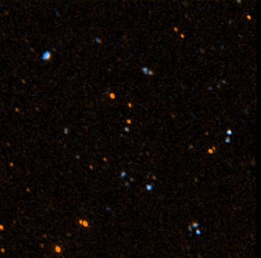
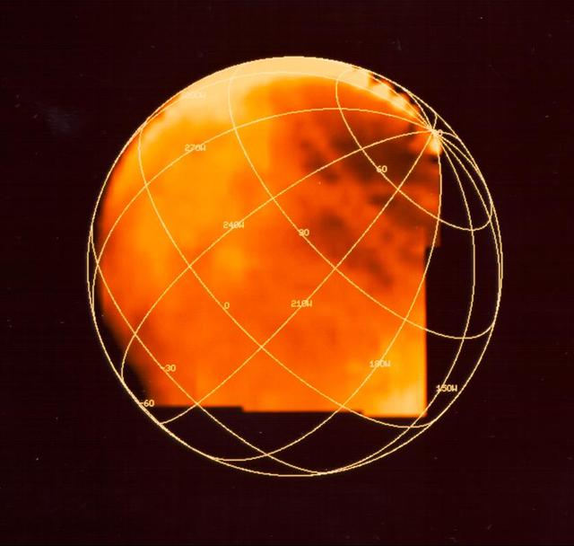
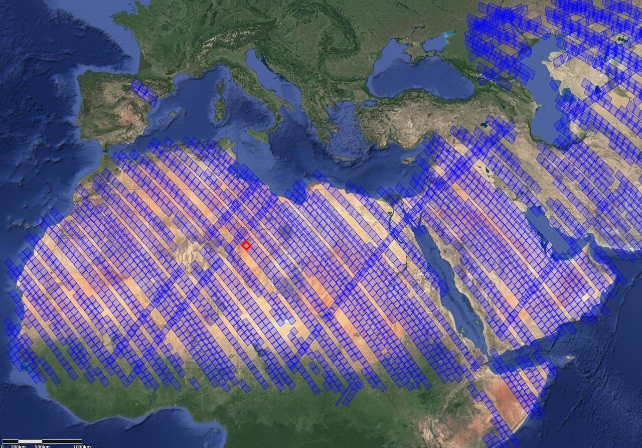
NASA's EMIT Measures Surface Dust in North Africa, Europe, the Middle East, Central Asia
The National Aeronautics and Space Administration (NASA) Lewis Research Center’s Convair F-106B Delta Dart equipped with air sampling equipment in the mid-1970s. NASA Lewis created and managed the Global Air Sampling Program (GASP) in 1972 in partnership with several airline companies. NASA researchers used the airliners’ Boeing 747 aircraft to gather air samples to determine the amount of pollution present in the stratosphere.      Private companies developed the air sampling equipment for the GASP program, and Lewis created a particle collector. The collector was flight tested on NASA Lewis’ F-106B in the summer of 1973. The sampling equipment was automatically operated once the proper altitude was achieved. The sampling instruments collected dust particles in the air so their chemical composition could be analyzed. The equipment analyzed one second’s worth of data at a time. The researchers also monitored carbon monoxide, monozide, ozone, and water vapor.    The 747 flights began in December 1974 and soon included four airlines flying routes all over the globe. The F-106B augmented the airline data with sampling of its own, seen here. It gathered samples throughout this period from locations such as New Mexico, Texas, Michigan, and Ohio. In July 1977 the F-106B flew eight GASP flights in nine days over Alaska to supplement the earlier data gathered by the airlines.
Convair F-106B Delta Dart with Air Sampling Equipment
In this 30-second exposure, NASA's Boeing Crew Flight Test Starliner spacecraft lands uncrewed, Friday, Sept. 6, 2024 Mountain Time, at White Sands, New Mexico. This approach allows NASA and Boeing to continue gathering testing data on the spacecraft. Photo Credit: (NASA/Aubrey Gemignani)
NASA’s Boeing Crew Flight Test Landing
Having reached the halfway point in a 12-test RS-25 certification series, teams at NASA’s Stennis Space Center will install a second production nozzle (shown) on the engine to gather additional performance data during the remaining scheduled hot fires.
NASA Marks Halfway Point for Artemis Moon Rocket Engine Certification Series
In this 30-second exposure, NASA's Boeing Crew Flight Test Starliner spacecraft lands uncrewed, Friday, Sept. 6, 2024, at White Sands, New Mexico. This approach allows NASA and Boeing to continue gathering testing data on the spacecraft. Photo Credit: (NASA/Aubrey Gemignani)
NASA’s Boeing Crew Flight Test Landing
STS104-E-5022 (14 July 2001) --- Astronaut Michael L. Gernhardt, STS-104 mission specialist, gathers flight data prior to rendezvous between the Space Shuttle Atlantis and the International Space Station (ISS).  A crew mate took this picture with a digital still camera.
MS Gernhardt on flight deck
NASA pilots, engineers, and communications specialists brief the day's operations prior to a supersonic research flight for QSF18, taking off from Ellington Field in Houston, Texas. The flights are meant to validate NASA's techniques and technology for gather community feedback data for X-59's Low-Boom Flight Demonstration mission.
NASA QSF18 Flight Crew Briefs Test Flight
ISS034-E-035764 (28 Jan. 2013) --- In the International Space Station?s Poisk Mini-Research Module 2 (MRM2), Russian cosmonaut Roman Romanenko, Expedition 34 flight engineer, works with the Coulomb Crystal experiment, which gathers data about charged particles in a weightless environment.
Romanenko works with the Coulomb Crystal Experiment in the MRM-2
jsc2020e012431 (2/27/2020) --- A preflight view of Neutron-1 internal components and harnessing. The NanoRacks-NEUTRON-1 investigation maps neutron abundance in low-Earth orbit. Data gathered on global neutron counts could contribute to better understanding of the complex relationship between Earth and the Sun.   Image courtesy of HSFL
Neutron-1 3U CubeSat
The Uninhabited Aerial Vehicle Synthetic Aperture Radar, UAVSAR, is prepared for installation onto NASA’s C-20A aircraft.  THE UAVSAR uses a technique called interferometry to detect and measure very subtle deformations in the Earth’s surface, and the pod is specially designed to be interoperable with unmanned aircraft in the future.  It will gather data from Gabon, Africa in September of 2023.
UAVSAR pod install
Kevin Knutson sits at a station in the main Blue Control Room at NASA’s Armstrong Flight Research Center in California used during complex flight missions to house the many technical discipline experts required to gather all of the required data and to enhance mission safety.
DATR Supports Space Communication, Research Flights
NASA pilots, engineers, and communications specialists brief the day’s operations prior to a supersonic research flight for QSF18, taking off from Ellington Field in Houston, Texas. The flights are meant to validate NASA’s techniques and technology for gather community feedback data for X-59’s Low-Boom Flight Demonstration mission.
NASA QSF18 Flight Crew Briefs Test Flight
The Uninhabited Aerial Vehicle Synthetic Aperture Radar, UAVSAR, is prepared for installation onto NASA’s C-20A aircraft.  THE UAVSAR uses a technique called interferometry to detect and measure very subtle deformations in the Earth’s surface, and the pod is specially designed to be interoperable with unmanned aircraft in the future.  It will gather data from Gabon, Africa in September of 2023.
UAVSAR pod install
NASA pilots, engineers, and communications specialists brief the day’s operations prior to a supersonic research flight for QSF18, taking off from Ellington Field in Houston, Texas. The flights are meant to validate NASA’s techniques and technology for gather community feedback data for X-59’s Low-Boom Flight Demonstration mission.
NASA QSF18 Flight Crew Briefs Test Flight
Boeing and NASA teams meet before NASA's Boeing Crew Flight Test Starliner spacecraft lands uncrewed, Friday, Sept. 6, 2024 Mountain Time at White Sands, New Mexico. This approach allows NASA and Boeing to continue gathering testing data on the spacecraft. Photo Credit: (NASA/Aubrey Gemignani)
NASA’s Boeing Crew Flight Test Landing
The Uninhabited Aerial Vehicle Synthetic Aperture Radar, UAVSAR, is prepared for installation onto NASA’s C-20A aircraft.  THE UAVSAR uses a technique called interferometry to detect and measure very subtle deformations in the Earth’s surface, and the pod is specially designed to be interoperable with unmanned aircraft in the future.  It will gather data from Gabon, Africa in September of 2023.
UAVSAR pod install
NASA’s Global Hawk aircraft was deployed to Florida from Armstrong Flight Research Center at Edwards, CA. on Oct. 6 to monitor and take scientific measurements of Hurricane Matthew.  The unmanned Global Hawk will gather scientific data in support of NOAA’s Sensing Hazards with Operational Unmanned Technology (SHOUT) mission.
AFRC2016-0292-08
A rooftop pedestal and telemetry dish gathered information from research aircraft at Building 4800 at NASA’s Armstrong Flight Research Center in Edwards, California. The pedestal was used since the 1950s to 2015 to house different dishes to collect data from research aircraft. On Oct. 4, 2024, a helicopter was used to remove the pedestal from the roof.
Helicopter Removes Historic Rooftop Pedestal
Boeing and NASA teams are seen before NASA's Boeing Crew Flight Test Starliner spacecraft lands uncrewed, Friday, Sept. 6, 2024 Mountain Time at White Sands, New Mexico. This approach allows NASA and Boeing to continue gathering testing data on the spacecraft. Photo Credit: (NASA/Aubrey Gemignani)
NASA’s Boeing Crew Flight Test Landing
NASA pilots, engineers, and communications specialists brief the day’s operations prior to a supersonic research flight for QSF18, taking off from Ellington Field in Houston, Texas. The flights are meant to validate NASA’s techniques and technology for gather community feedback data for X-59’s Low-Boom Flight Demonstration mission.
NASA QSF18 Flight Crew Briefs Test Flight
The Uninhabited Aerial Vehicle Synthetic Aperture Radar, UAVSAR, is prepared for installation onto NASA’s C-20A aircraft.  THE UAVSAR uses a technique called interferometry to detect and measure very subtle deformations in the Earth’s surface, and the pod is specially designed to be interoperable with unmanned aircraft in the future.  It will gather data from Gabon, Africa in September of 2023.
UAVSAR pod critical lift
The Uninhabited Aerial Vehicle Synthetic Aperture Radar, UAVSAR, is prepared for installation onto NASA’s C-20A aircraft.  THE UAVSAR uses a technique called interferometry to detect and measure very subtle deformations in the Earth’s surface, and the pod is specially designed to be interoperable with unmanned aircraft in the future.  It will gather data from Gabon, Africa in September of 2023.
UAVSAR pod install
NASA's Galaxy Evolution Explorer took this image on May 21 and 22, 2003. The image was made from data gathered by the two channels of the spacecraft camera during the mission's "first light" milestone. It shows about 100 celestial objects in the constellation Hercules. The reddish objects represent those detected by the camera's near ultraviolet channel over a 5-minute period, while bluish objects were detected over a 3-minute period by the camera's far ultraviolet channel.  The Galaxy Evolution Explorer's first light images are dedicated to the crew of the Space Shuttle Columbia. The Hercules region was directly above Columbia when it made its last contact with NASA Mission Control on February 1, over the skies of Texas.  The Galaxy Evolution Explorer launched on April 28 on a mission to map the celestial sky in the ultraviolet and determine the history of star formation in the universe over the last 10 billion years. http://photojournal.jpl.nasa.gov/catalog/PIA04281
GALEX 1st Light Near and Far Ultraviolet -100
NASA engineers continued to collect test performance data on the new J-2X rocket engine at Stennis Space Center with a 250-second test Sept. 14. The test on the A-2 Test Stand was the 19th in a series of firings to gather critical data for continued development of the engine. The J-2X is being developed by Pratt and Whitney Rocketdyne for NASA's Marshall Space Flight Center in Huntsville, Ala. It is the first liquid oxygen and liquid hydrogen rocket engine rated to carry humans into space to be developed in 40 years.
J-2X engine
KENNEDY SPACE CENTER, FLA. --   In the hypergolic maintenance facility at NASA's Kennedy Space Center, elements of the ARES I-X Roll Control System, or RoCS, will undergo testing.  The RoCS Servicing Simulation Test is to gather data that will be used to help certify the ground support equipment design and validate the servicing requirements and processes. The RoCS is part of the Interstage structure, the lowest axial segment of the Upper Stage Simulator.  In an effort to reduce costs and meet the  schedule, most of the ground support equipment that will be used for the RoCS servicing is of space shuttle heritage.  This high-fidelity servicing simulation will provide confidence that servicing requirements can be met with the heritage system.  At the same time, the test will gather process data that will be used to modify or refine the equipment and processes to be used for the actual flight element.  Photo credit: NASA/Kim Shiflett
KSC-08pd0081
KENNEDY SPACE CENTER, FLA. --  In the hypergolic maintenance facility at NASA's Kennedy Space Center, a technician (right) adjusts equipment during testing of the Ares I-X Roll Control System, or RoCS.  The RoCS Servicing Simulation Test is to gather data that will be used to help certify the ground support equipment design and validate the servicing requirements and processes. The RoCS is part of the Interstage structure, the lowest axial segment of the Upper Stage Simulator.  In an effort to reduce costs and meet the  schedule, most of the ground support equipment that will be used for the RoCS servicing is of space shuttle heritage.  This high-fidelity servicing simulation will provide confidence that servicing requirements can be met with the heritage system.  At the same time, the test will gather process data that will be used to modify or refine the equipment and processes to be used for the actual flight element.  Photo credit: NASA/Kim Shiflett
KSC-08pd0090
KENNEDY SPACE CENTER, FLA. --  In the hypergolic maintenance facility at NASA's Kennedy Space Center,  technicians monitor equipment during testing of the Ares I-X Roll Control System, or RoCS.  The RoCS Servicing Simulation Test is to gather data that will be used to help certify the ground support equipment design and validate the servicing requirements and processes. The RoCS is part of the Interstage structure, the lowest axial segment of the Upper Stage Simulator.  In an effort to reduce costs and meet the  schedule, most of the ground support equipment that will be used for the RoCS servicing is of space shuttle heritage.  This high-fidelity servicing simulation will provide confidence that servicing requirements can be met with the heritage system.  At the same time, the test will gather process data that will be used to modify or refine the equipment and processes to be used for the actual flight element.  Photo credit: NASA/Kim Shiflett
KSC-08pd0089
KENNEDY SPACE CENTER, FLA. --  In the hypergolic maintenance facility at NASA's Kennedy Space Center,  technicians monitor equipment during testing of the Ares I-X Roll Control System, or RoCS.  The RoCS Servicing Simulation Test is to gather data that will be used to help certify the ground support equipment design and validate the servicing requirements and processes. The RoCS is part of the Interstage structure, the lowest axial segment of the Upper Stage Simulator.  In an effort to reduce costs and meet the  schedule, most of the ground support equipment that will be used for the RoCS servicing is of space shuttle heritage.  This high-fidelity servicing simulation will provide confidence that servicing requirements can be met with the heritage system.  At the same time, the test will gather process data that will be used to modify or refine the equipment and processes to be used for the actual flight element.  Photo credit: NASA/Kim Shiflett
KSC-08pd0092
A jar of peanuts is seen sitting on a console in mission control of the Space Flight Operations Center as the Cassini mission team await the final downlink of the spacecraft's data recorder, Thursday, Sept. 14, 2017 at NASA's Jet Propulsion Laboratory in Pasadena, California. Since its arrival in 2004, the Cassini-Huygens mission has been a discovery machine, revolutionizing our knowledge of the Saturn system and captivating us with data and images never before obtained with such detail and clarity. On Sept. 15, 2017, operators will deliberately plunge the spacecraft into Saturn, as Cassini gathered science until the end. The “plunge” ensures Saturn’s moons will remain pristine for future exploration. During Cassini’s final days, mission team members from all around the world gathered at NASA’s Jet Propulsion Laboratory, Pasadena, California, to celebrate the achievements of this historic mission. Photo Credit: (NASA/Joel Kowsky)
Cassini End of Mission
Cassini program manager at JPL, Earl Maize, watches monitors in mission control of the Space Flight Operations Center as the Cassini spacecraft begins downlink data through NASA's Deep Space Network, Thursday, Sept. 14, 2017 at NASA's Jet Propulsion Laboratory in Pasadena, California. Since its arrival in 2004, the Cassini-Huygens mission has been a discovery machine, revolutionizing our knowledge of the Saturn system and captivating us with data and images never before obtained with such detail and clarity. On Sept. 15, 2017, operators will deliberately plunge the spacecraft into Saturn, as Cassini gathered science until the end. The “plunge” ensures Saturn’s moons will remain pristine for future exploration. During Cassini’s final days, mission team members from all around the world gathered at NASA’s Jet Propulsion Laboratory, Pasadena, California, to celebrate the achievements of this historic mission. Photo Credit: (NASA/Joel Kowsky)
Cassini End of Mission
KENNEDY SPACE CENTER, FLA. --  In the hypergolic maintenance facility at NASA's Kennedy Space Center, technicians get ready to begin testing elements of the Ares I-X Roll Control System, or RoCS.  The RoCS Servicing Simulation Test is to gather data that will be used to help certify the ground support equipment design and validate the servicing requirements and processes. The RoCS is part of the Interstage structure, the lowest axial segment of the Upper Stage Simulator.  In an effort to reduce costs and meet the  schedule, most of the ground support equipment that will be used for the RoCS servicing is of space shuttle heritage.  This high-fidelity servicing simulation will provide confidence that servicing requirements can be met with the heritage system.  At the same time, the test will gather process data that will be used to modify or refine the equipment and processes to be used for the actual flight element.  Photo credit: NASA/Kim Shiflett
KSC-08pd0084
Cassini team members monitor data from the spacecraft as it makes its final plunge into Saturn, Friday, Sept. 15, 2017 at NASA's Jet Propulsion Laboratory in Pasadena, California. Since its arrival in 2004, the Cassini-Huygens mission has been a discovery machine, revolutionizing our knowledge of the Saturn system and captivating us with data and images never before obtained with such detail and clarity. On Sept. 15, 2017, operators deliberately plunged the spacecraft into Saturn, as Cassini gathered science until the end. Loss of contact with the Cassini spacecraft occurred at 7:55 a.m. EDT (4:55 a.m. PDT). The “plunge” ensures Saturn’s moons will remain pristine for future exploration. During Cassini’s final days, mission team members from all around the world gathered at NASA’s Jet Propulsion Laboratory, Pasadena, California, to celebrate the achievements of this historic mission. Photo Credit: (NASA/Joel Kowsky)
Cassini End of Mission
KENNEDY SPACE CENTER, FLA. --   In the hypergolic maintenance facility at NASA's Kennedy Space Center, a technician monitors equipment during testing of the Ares I-X Roll Control System, or RoCS.  The RoCS Servicing Simulation Test is to gather data that will be used to help certify the ground support equipment design and validate the servicing requirements and processes. The RoCS is part of the Interstage structure, the lowest axial segment of the Upper Stage Simulator.  In an effort to reduce costs and meet the  schedule, most of the ground support equipment that will be used for the RoCS servicing is of space shuttle heritage.  This high-fidelity servicing simulation will provide confidence that servicing requirements can be met with the heritage system.  At the same time, the test will gather process data that will be used to modify or refine the equipment and processes to be used for the actual flight element.  Photo credit: NASA_Kim Shiflett
KSC-08pd-0086
KENNEDY SPACE CENTER, FLA. --   In the hypergolic maintenance facility at NASA's Kennedy Space Center, a technician adjusts equipment during testing of the Ares I-X Roll Control System, or RoCS.  The RoCS Servicing Simulation Test is to gather data that will be used to help certify the ground support equipment design and validate the servicing requirements and processes. The RoCS is part of the Interstage structure, the lowest axial segment of the Upper Stage Simulator.  In an effort to reduce costs and meet the  schedule, most of the ground support equipment that will be used for the RoCS servicing is of space shuttle heritage.  This high-fidelity servicing simulation will provide confidence that servicing requirements can be met with the heritage system.  At the same time, the test will gather process data that will be used to modify or refine the equipment and processes to be used for the actual flight element.  Photo credit: NASA/Kim Shiflett
KSC-08pd0087
Spacecraft operations team manager for the Cassini mission at Saturn, Julie Webster, watches monitors in mission control of the Space Flight Operations Center as the Cassini spacecraft begins downlink data through NASA's Deep Space Network, Thursday, Sept. 14, 2017 at NASA's Jet Propulsion Laboratory in Pasadena, California. Since its arrival in 2004, the Cassini-Huygens mission has been a discovery machine, revolutionizing our knowledge of the Saturn system and captivating us with data and images never before obtained with such detail and clarity. On Sept. 15, 2017, operators will deliberately plunge the spacecraft into Saturn, as Cassini gathered science until the end. The “plunge” ensures Saturn’s moons will remain pristine for future exploration. During Cassini’s final days, mission team members from all around the world gathered at NASA’s Jet Propulsion Laboratory, Pasadena, California, to celebrate the achievements of this historic mission. Photo Credit: (NASA/Joel Kowsky)
Cassini End of Mission
KENNEDY SPACE CENTER, FLA. --   In the hypergolic maintenance facility at NASA's Kennedy Space Center, some of the internal elements seen here of the ARES I-X Roll Control System, or RoCS, will undergo testing.  The RoCS Servicing Simulation Test is to gather data that will be used to help certify the ground support equipment design and validate the servicing requirements and processes. The RoCS is part of the Interstage structure, the lowest axial segment of the Upper Stage Simulator.  In an effort to reduce costs and meet the  schedule, most of the ground support equipment that will be used for the RoCS servicing is of space shuttle heritage.  This high-fidelity servicing simulation will provide confidence that servicing requirements can be met with the heritage system.  At the same time, the test will gather process data that will be used to modify or refine the equipment and processes to be used for the actual flight element.  Photo credit: NASA/Kim Shiflett
KSC-08pd0082
KENNEDY SPACE CENTER, FLA. --  In the hypergolic maintenance facility at NASA's Kennedy Space Center, a technician adjusts equipment during testing of the Ares I-X Roll Control System, or RoCS.  The RoCS Servicing Simulation Test is to gather data that will be used to help certify the ground support equipment design and validate the servicing requirements and processes. The RoCS is part of the Interstage structure, the lowest axial segment of the Upper Stage Simulator.  In an effort to reduce costs and meet the  schedule, most of the ground support equipment that will be used for the RoCS servicing is of space shuttle heritage.  This high-fidelity servicing simulation will provide confidence that servicing requirements can be met with the heritage system.  At the same time, the test will gather process data that will be used to modify or refine the equipment and processes to be used for the actual flight element.  Photo credit: NASA/Kim Shiflett
KSC-08pd0091
Cassini program manager at JPL, Earl Maize, is seen in mission control of the Space Flight Operations Center as the Cassini team wait for the spacecraft to establish a connection with NASA's Deep Space Network to begin the final playback of its data recorder, Thursday, Sept. 14, 2017 at NASA's Jet Propulsion Laboratory in Pasadena, California. Since its arrival in 2004, the Cassini-Huygens mission has been a discovery machine, revolutionizing our knowledge of the Saturn system and captivating us with data and images never before obtained with such detail and clarity. On Sept. 15, 2017, operators will deliberately plunge the spacecraft into Saturn, as Cassini gathered science until the end. The “plunge” ensures Saturn’s moons will remain pristine for future exploration. During Cassini’s final days, mission team members from all around the world gathered at NASA’s Jet Propulsion Laboratory, Pasadena, California, to celebrate the achievements of this historic mission. Photo Credit: (NASA/Joel Kowsky)
Cassini End of Mission
KENNEDY SPACE CENTER, FLA. --   In the hypergolic maintenance facility at NASA's Kennedy Space Center,  technicians monitor equipment during testing of the Ares I-X Roll Control System, or RoCS.  The RoCS Servicing Simulation Test is to gather data that will be used to help certify the ground support equipment design and validate the servicing requirements and processes. The RoCS is part of the Interstage structure, the lowest axial segment of the Upper Stage Simulator.  In an effort to reduce costs and meet the  schedule, most of the ground support equipment that will be used for the RoCS servicing is of space shuttle heritage.  This high-fidelity servicing simulation will provide confidence that servicing requirements can be met with the heritage system.  At the same time, the test will gather process data that will be used to modify or refine the equipment and processes to be used for the actual flight element.  Photo credit: NASA/Kim Shiflett
KSC-08pd0088
A monitor shows the status of NASA's Deep Space Network as it receives data from the Cassini spacecraft, Friday, Sept. 15, 2017 in the Charles Elachi Mission Control Center in the Space Flight Operation Center at NASA's Jet Propulsion Laboratory in Pasadena, California. Since its arrival in 2004, the Cassini-Huygens mission has been a discovery machine, revolutionizing our knowledge of the Saturn system and captivating us with data and images never before obtained with such detail and clarity. On Sept. 15, 2017, operators will deliberately plunge the spacecraft into Saturn, as Cassini gathered science until the end. The “plunge” ensures Saturn’s moons will remain pristine for future exploration. During Cassini’s final days, mission team members from all around the world gathered at NASA’s Jet Propulsion Laboratory, Pasadena, California, to celebrate the achievements of this historic mission. Photo Credit: (NASA/Joel Kowsky)
Cassini End of Mission
KENNEDY SPACE CENTER, FLA. --  In the hypergolic maintenance facility at NASA's Kennedy Space Center, technicians look at some of the elements to be tested in the Ares I-X Roll Control System, or RoCS.  The RoCS Servicing Simulation Test is to gather data that will be used to help certify the ground support equipment design and validate the servicing requirements and processes. The RoCS is part of the Interstage structure, the lowest axial segment of the Upper Stage Simulator.  In an effort to reduce costs and meet the  schedule, most of the ground support equipment that will be used for the RoCS servicing is of space shuttle heritage.  This high-fidelity servicing simulation will provide confidence that servicing requirements can be met with the heritage system.  At the same time, the test will gather process data that will be used to modify or refine the equipment and processes to be used for the actual flight element.  Photo credit: NASA/Kim Shiflett
KSC-08pd0083