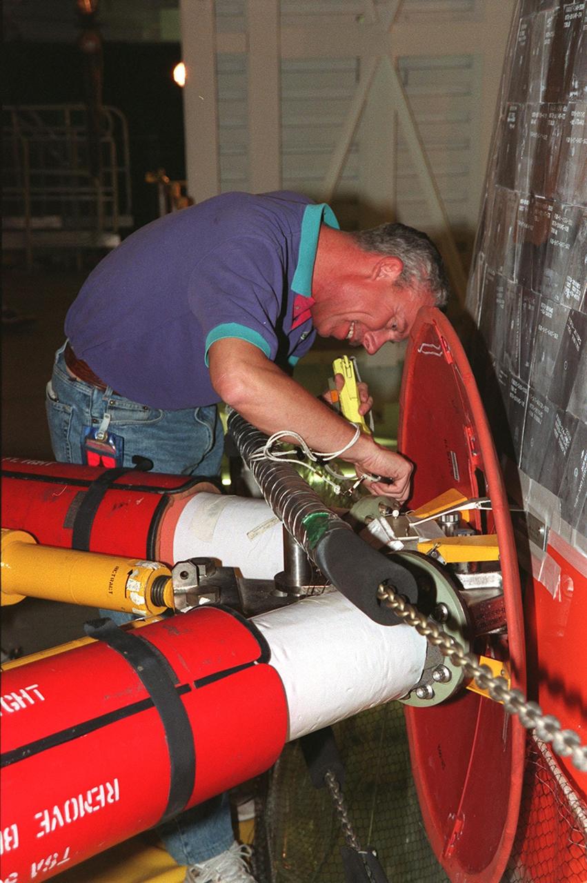
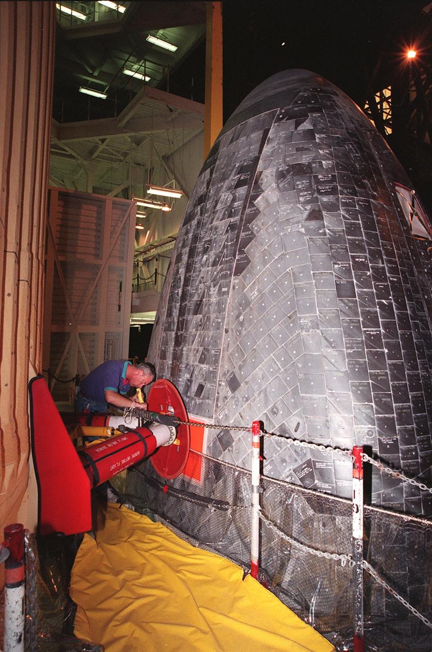
KENNEDY SPACE CENTER, FLA. -- In the Vehicle Assembly Building, Ken Strite, NASA Quality Control, inspects the connection between Space Shuttle Discovery and the external tank that will be used to launch mission STS-103 in early December. This 10-day mission is designed to replace aging parts on the nine-year-old Hubble Space Telescope and to upgrade some of its functioning systems. During the flight, the astronaut crew will replace all six of the observatory's gyroscopes, a fine guidance sensor, its main computer, and other equipment
KENNEDY SPACE CENTER, FLA. -- In the Vehicle Assembly Building, Ken Strite, NASA Quality Control, inspects the connection between Space Shuttle Discovery and the external tank that will be used to launch mission STS-103 in early December. This 10-day mission is designed to replace aging parts on the nine-year-old Hubble Space Telescope and to upgrade some of its functioning systems. During the flight, the astronaut crew will replace all six of the observatory's gyroscopes, a fine guidance sensor, its main computer, and other equipment
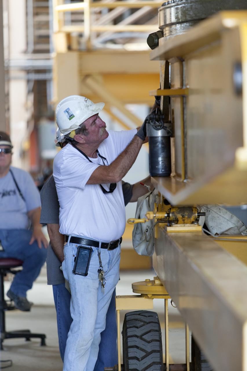
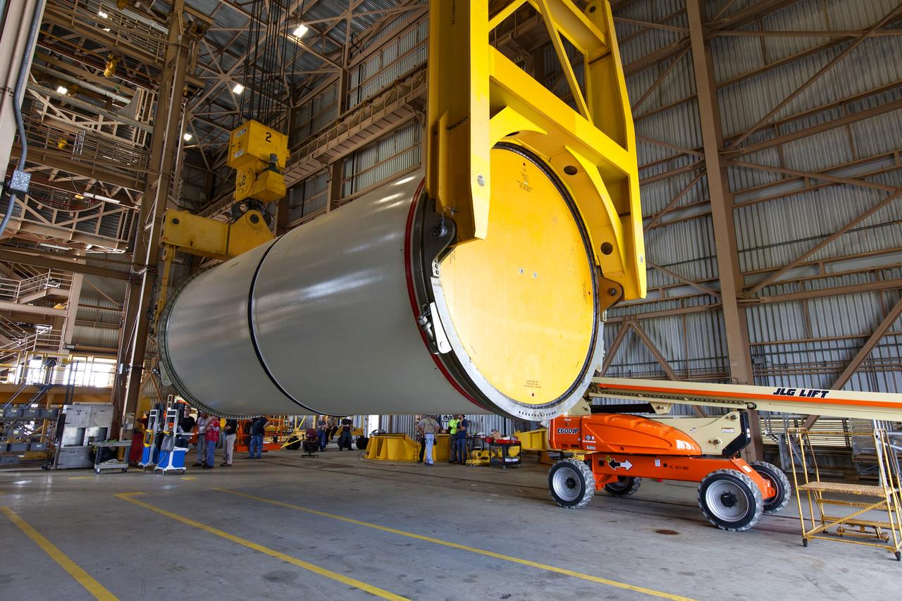
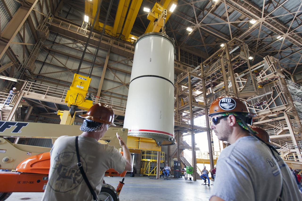
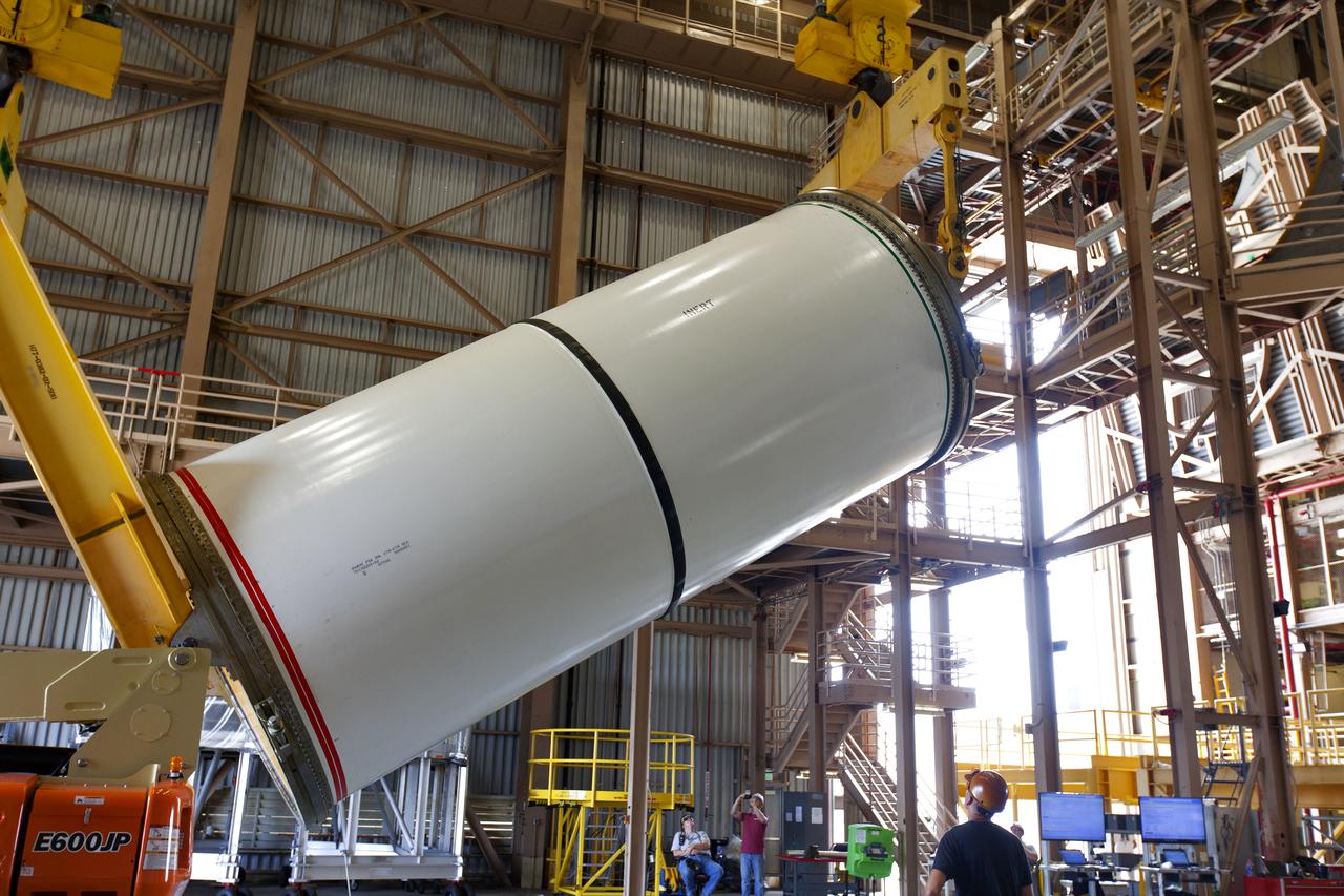
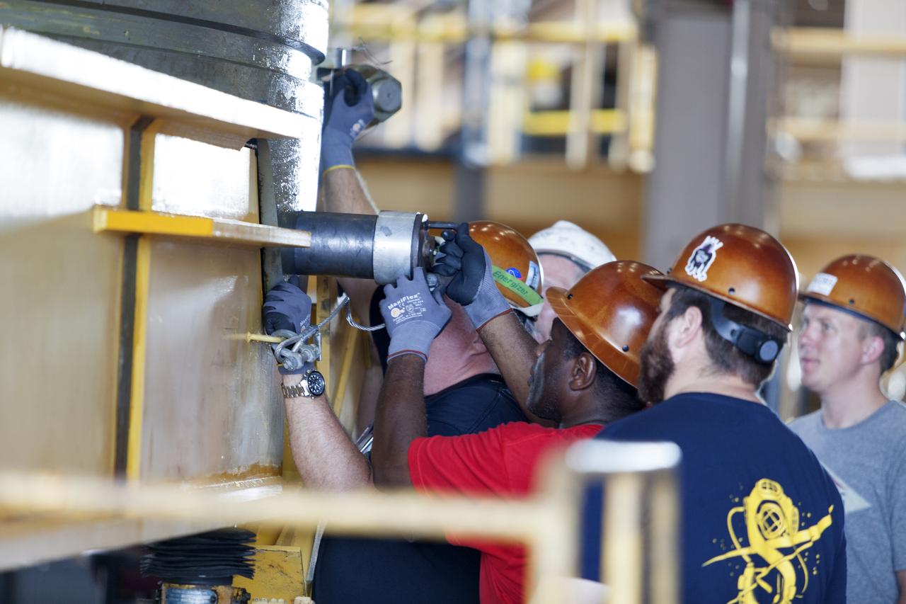
A Jacobs technician, on the Test and Operations Support Contract, checks bolt fittings during practice crane operations with an inert booster rocket segment in the Rotation, Processing and Surge Facility on June 22, 2018, at NASA's Kennedy Space Center in Florida. Dual cranes will be used to move the segment from vertical to horizontal, a maneuver known as a "breakover rotation." As part of routine processing operations for the agency's Space Launch System (SLS) rocket, the RPSF team will receive all of the solid rocket fuel segments for inspection and preparation prior to transporting them to the Vehicle Assembly Building for stacking on the mobile launcher. Many pathfinding operations are being done to prepare for launch of the SLS and Orion spacecraft on Exploration Mission-1 and deep space missions.
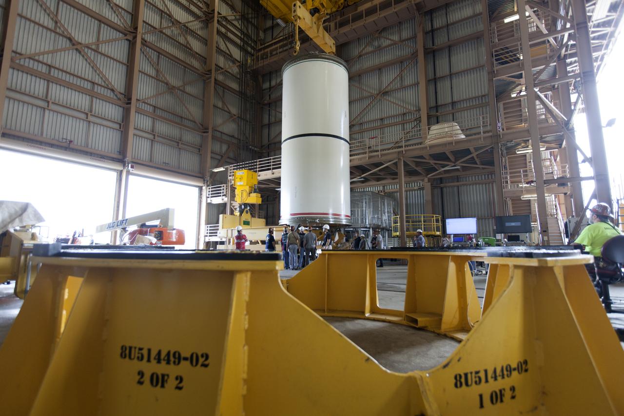
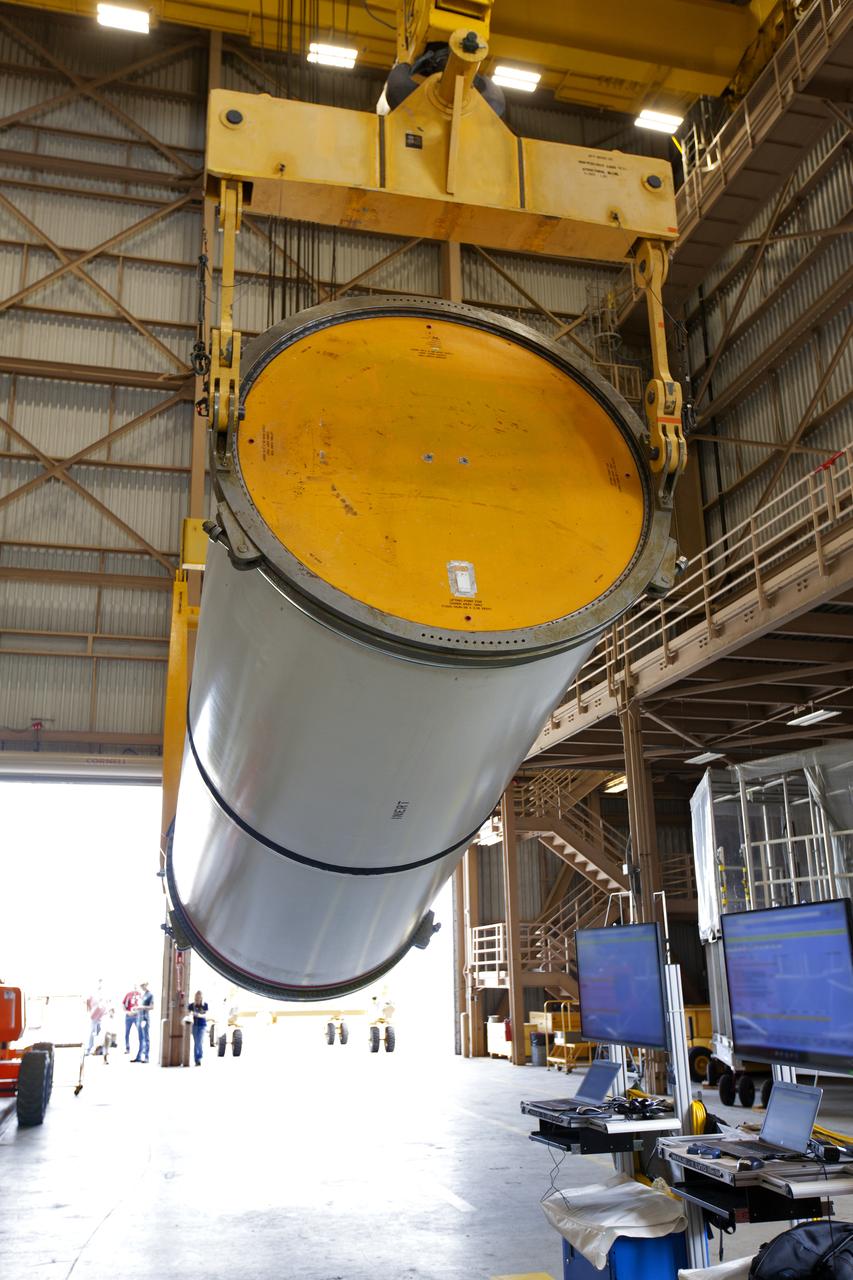
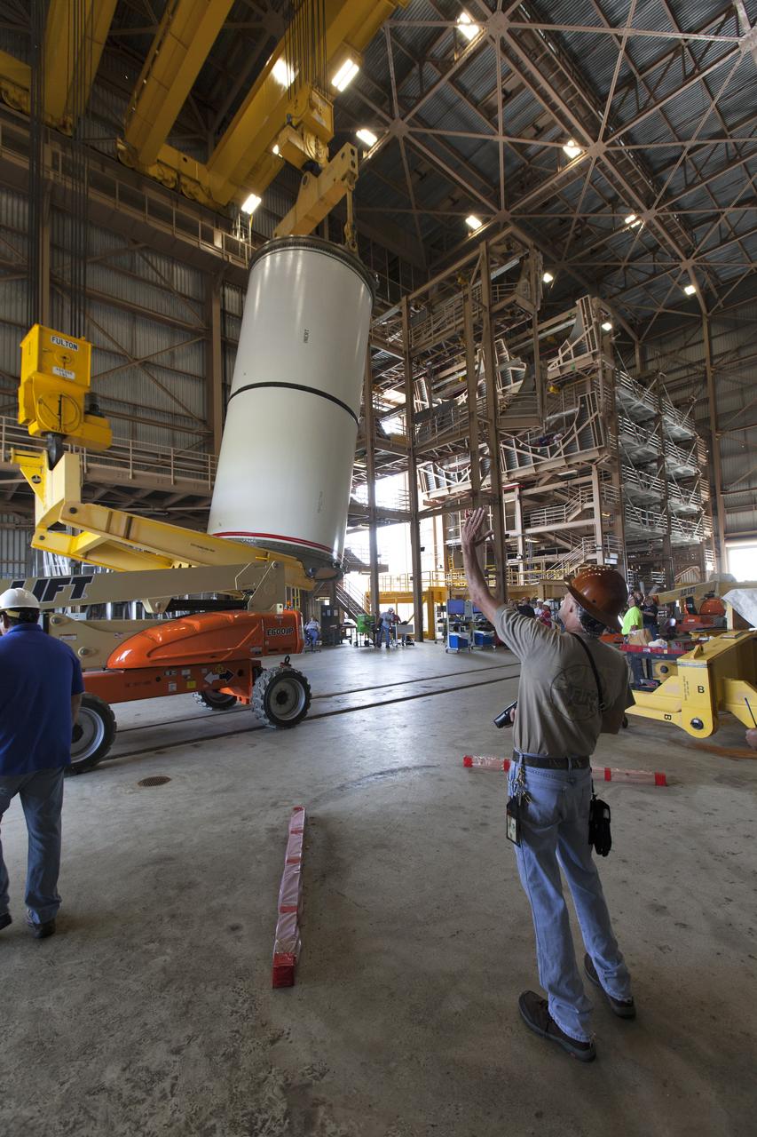
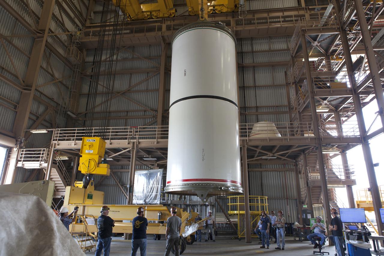
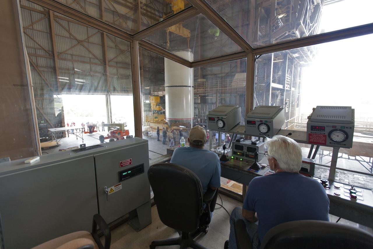
Jacobs technicians, on the Test and Operations Support Contract, practice crane operations with an inert booster rocket segment in the Rotation, Processing and Surge Facility on June 22, 2018, at NASA's Kennedy Space Center in Florida. Dual cranes are being used to move the segment from vertical to horizontal, a maneuver known as a "breakover rotation." As part of routine processing operations for the agency's Space Launch System (SLS) rocket, the RPSF team will receive all of the solid rocket fuel segments for inspection and preparation prior to transporting them to the Vehicle Assembly Building for stacking on the mobile launcher. Many pathfinding operations are being done to prepare for launch of the SLS and Orion spacecraft on Exploration Mission-1 and deep space missions.
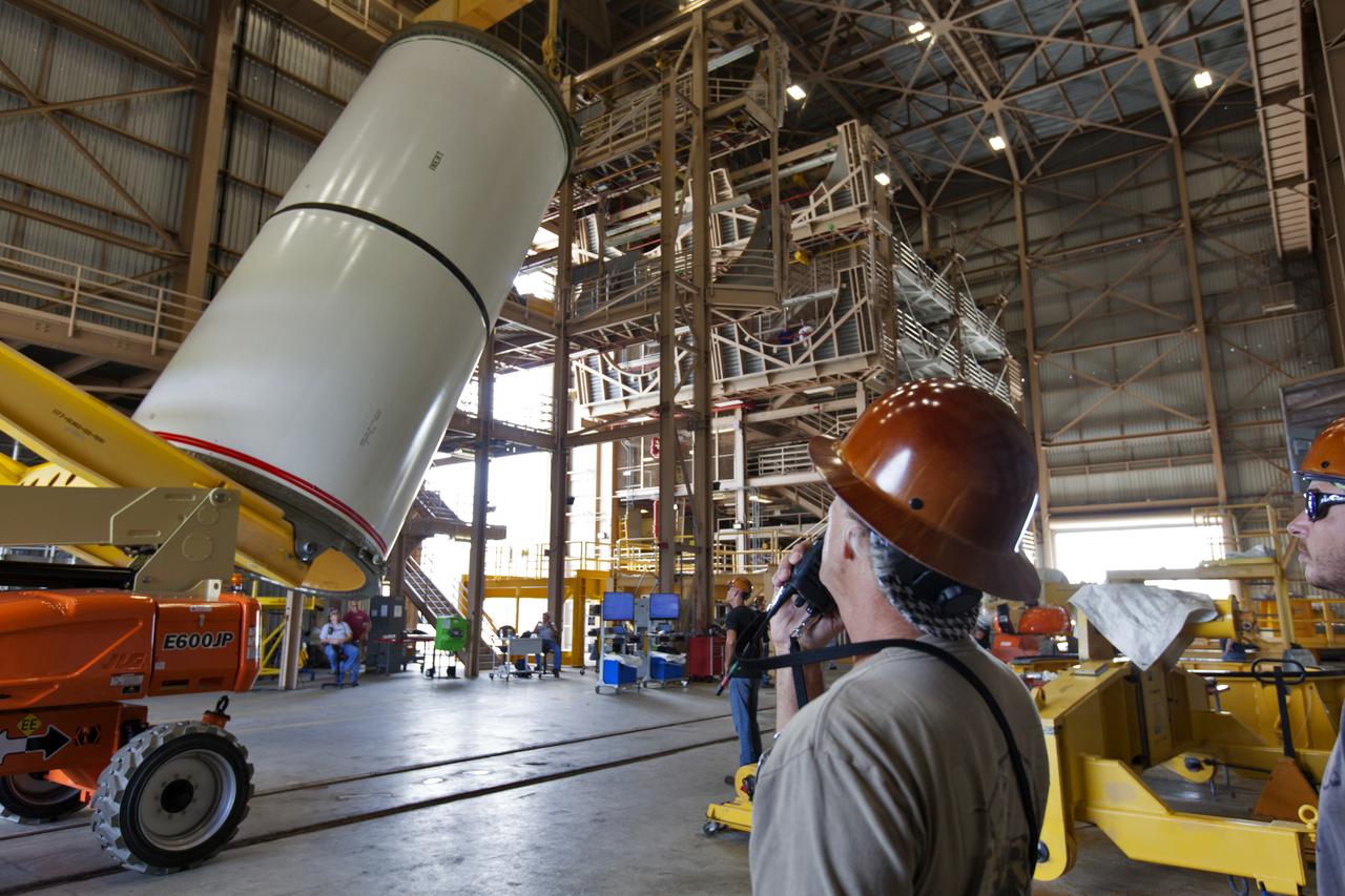
Jacobs technicians, on the Test and Operations Support Contract, practice crane operations with an inert booster rocket segment in the Rotation, Processing and Surge Facility on June 22, 2018, at NASA's Kennedy Space Center in Florida. Dual cranes were used to move the segment from vertical to horizontal, a maneuver known as a "breakover rotation." As part of routine processing operations for the agency's Space Launch System (SLS) rocket, the RPSF team will receive all of the solid rocket fuel segments for inspection and preparation prior to transporting them to the Vehicle Assembly Building for stacking on the mobile launcher. Many pathfinding operations are being done to prepare for launch of the SLS and Orion spacecraft on Exploration Mission-1 and deep space missions.
Jacobs technicians, on the Test and Operations Support Contract, practice crane operations with an inert booster rocket segment in the Rotation, Processing and Surge Facility on June 22, 2018, at NASA's Kennedy Space Center in Florida. Dual cranes are used to move the segment from vertical to horizontal, a maneuver known as a "breakover rotation." As part of routine processing operations for the agency's Space Launch System (SLS) rocket, the RPSF team will receive all of the solid rocket fuel segments for inspection and preparation prior to transporting them to the Vehicle Assembly Building for stacking on the mobile launcher. Many pathfinding operations are being done to prepare for launch of the SLS and Orion spacecraft on Exploration Mission-1 and deep space missions.
Jacobs technicians, on the Test and Operations Support Contract, practice crane operations with an inert booster rocket segment in the Rotation, Processing and Surge Facility on June 22, 2018, at NASA's Kennedy Space Center in Florida. Dual cranes are being used to move the segment from vertical to horizontal, a maneuver known as a "breakover rotation." As part of routine processing operations for the agency's Space Launch System (SLS) rocket, the RPSF team will receive all of the solid rocket fuel segments for inspection and preparation prior to transporting them to the Vehicle Assembly Building for stacking on the mobile launcher. Many pathfinding operations are being done to prepare for launch of the SLS and Orion spacecraft on Exploration Mission-1 and deep space missions.
Jacobs technicians, on the Test and Operations Support Contract, practice crane operations with an inert booster rocket segment in the Rotation, Processing and Surge Facility on June 22, 2018, at NASA's Kennedy Space Center in Florida. Dual cranes are being used to move the segment from vertical to horizontal, a maneuver known as a "breakover rotation." As part of routine processing operations for the agency's Space Launch System (SLS) rocket, the RPSF team will receive all of the solid rocket fuel segments for inspection and preparation prior to transporting them to the Vehicle Assembly Building for stacking on the mobile launcher. Many pathfinding operations are being done to prepare for launch of the SLS and Orion spacecraft on Exploration Mission-1 and deep space missions.
Jacobs technicians, on the Test and Operations Support Contract, practice crane operations with an inert booster rocket segment in the Rotation, Processing and Surge Facility on June 22, 2018, at NASA's Kennedy Space Center in Florida. Dual cranes are being used to move the segment from vertical to horizontal, a maneuver known as a "breakover rotation." As part of routine processing operations for the agency's Space Launch System (SLS) rocket, the RPSF team will receive all of the solid rocket fuel segments for inspection and preparation prior to transporting them to the Vehicle Assembly Building for stacking on the mobile launcher. Many pathfinding operations are being done to prepare for launch of the SLS and Orion spacecraft on Exploration Mission-1 and deep space missions.
Jacobs technicians, on the Test and Operations Support Contract, practice crane operations with an inert booster rocket segment in the Rotation, Processing and Surge Facility on June 22, 2018, at NASA's Kennedy Space Center in Florida. Dual cranes are being used to move the segment from vertical to horizontal, a maneuver known as a "breakover rotation." As part of routine processing operations for the agency's Space Launch System (SLS) rocket, the RPSF team will receive all of the solid rocket fuel segments for inspection and preparation prior to transporting them to the Vehicle Assembly Building for stacking on the mobile launcher. Many pathfinding operations are being done to prepare for launch of the SLS and Orion spacecraft on Exploration Mission-1 and deep space missions.
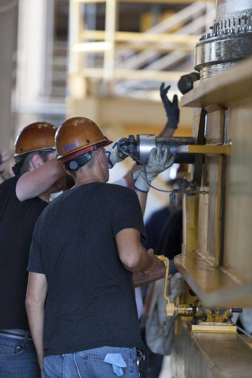
Jacobs technicians, on the Test and Operations Support Contract, check bolt fittings as they practice crane operations with an inert booster rocket segment in the Rotation, Processing and Surge Facility on June 22, 2018, at NASA's Kennedy Space Center in Florida. Dual cranes are being used to move the segment from vertical to horizontal, a maneuver known as a "breakover rotation." As part of routine processing operations for the agency's Space Launch System (SS) rocket, the RPSF team will receive all of the solid rocket fuel segments for inspection and preparation prior to transporting them to the Vehicle Assembly Building for stacking on the mobile launcher. Many pathfinding operations are being done to prepare for launch of the SLS and Orion spacecraft on Exploration Mission-1 and deep space missions.
Jacobs technicians, on the Test and Operations Support Contract, practice crane operations with an inert booster rocket segment in the Rotation, Processing and Surge Facility on June 22, 2018, at NASA's Kennedy Space Center in Florida. Dual cranes are being used to move the segment from vertical to horizontal, a maneuver known as a "breakover rotation." As part of routine processing operations for the agency's Space Launch System (SLS) rocket, the RPSF team will receive all of the solid rocket fuel segments for inspection and preparation prior to transporting them to the Vehicle Assembly Building for stacking on the mobile launcher. Many pathfinding operations are being done to prepare for launch of the SLS and Orion spacecraft on Exploration Mission-1 and deep space missions.
Jacobs technicians, on the Test and Operations Support Contract, practice crane operations with an inert booster rocket segment in the Rotation, Processing and Surge Facility on June 22, 2018, at NASA's Kennedy Space Center in Florida. Dual cranes are used to move the segment from vertical to horizontal, a maneuver known as a "breakover rotation." As part of routine processing operations for the agency's Space Launch System (SLS) rocket, the RPSF team will receive all of the solid rocket fuel segments for inspection and preparation prior to transporting them to the Vehicle Assembly Building for stacking on the mobile launcher. Many pathfinding operations are being done to prepare for launch of the SLS and Orion spacecraft on Exploration Mission-1 and deep space missions.
Jacobs technicians, on the Test and Operations Support Contract, check bolt fittings as they practice crane operations with an inert booster rocket segment in the Rotation, Processing and Surge Facility on June 22, 2018, at NASA's Kennedy Space Center in Florida. Dual cranes are being used to move the segment from vertical to horizontal, a maneuver known as a "breakover rotation." As part of routine processing operations for the agency's Space Launch System (SLS) rocket, the RPSF team will receive all of the solid rocket fuel segments for inspection and preparation prior to transporting them to the Vehicle Assembly Building for stacking on the mobile launcher. Many pathfinding operations are being done to prepare for launch of the SLS and Orion spacecraft on Exploration Mission-1 and deep space missions.
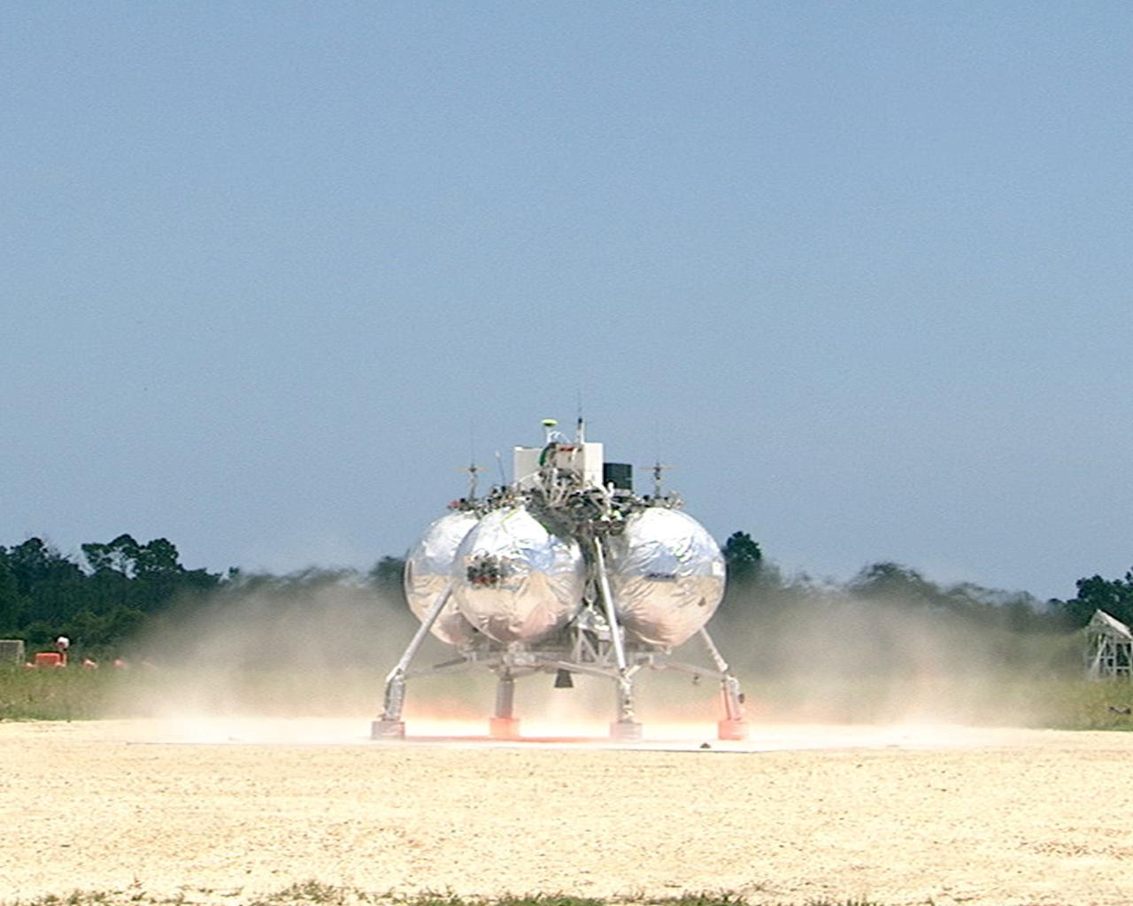
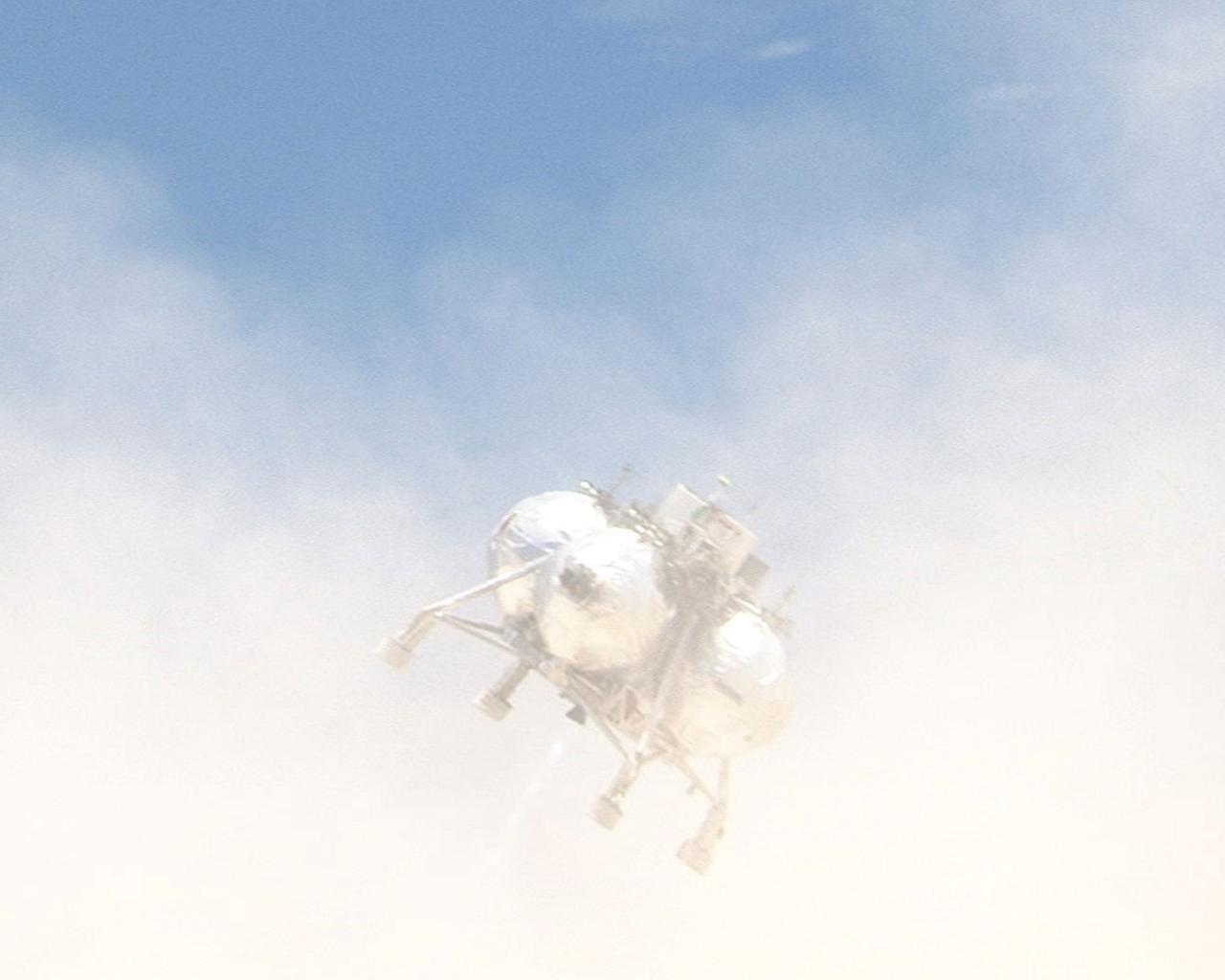
CAPE CANAVERAL, Fla. – At the Shuttle Landing Facility at NASA’s Kennedy Space Center in Florida, the Morpheus prototype lander begins to lift off of the ground during a free-flight test. Testing of the prototype lander had been ongoing at NASA’s Johnson Space Center in Houston in preparation for its first free-flight test at Kennedy Space Center. Morpheus was manufactured and assembled at JSC and Armadillo Aerospace. Morpheus is large enough to carry 1,100 pounds of cargo to the moon – for example, a humanoid robot, a small rover, or a small laboratory to convert moon dust into oxygen. The primary focus of the test is to demonstrate an integrated propulsion and guidance, navigation and control system that can fly a lunar descent profile to exercise the Autonomous Landing and Hazard Avoidance Technology, or ALHAT, safe landing sensors and closed-loop flight control. For more information on Project Morpheus, visit http://morpheuslander.jsc.nasa.gov/. Photo credit: NASA
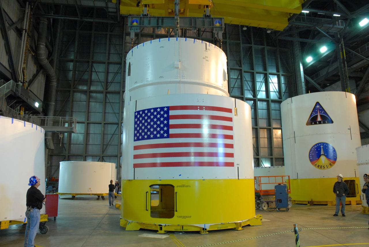
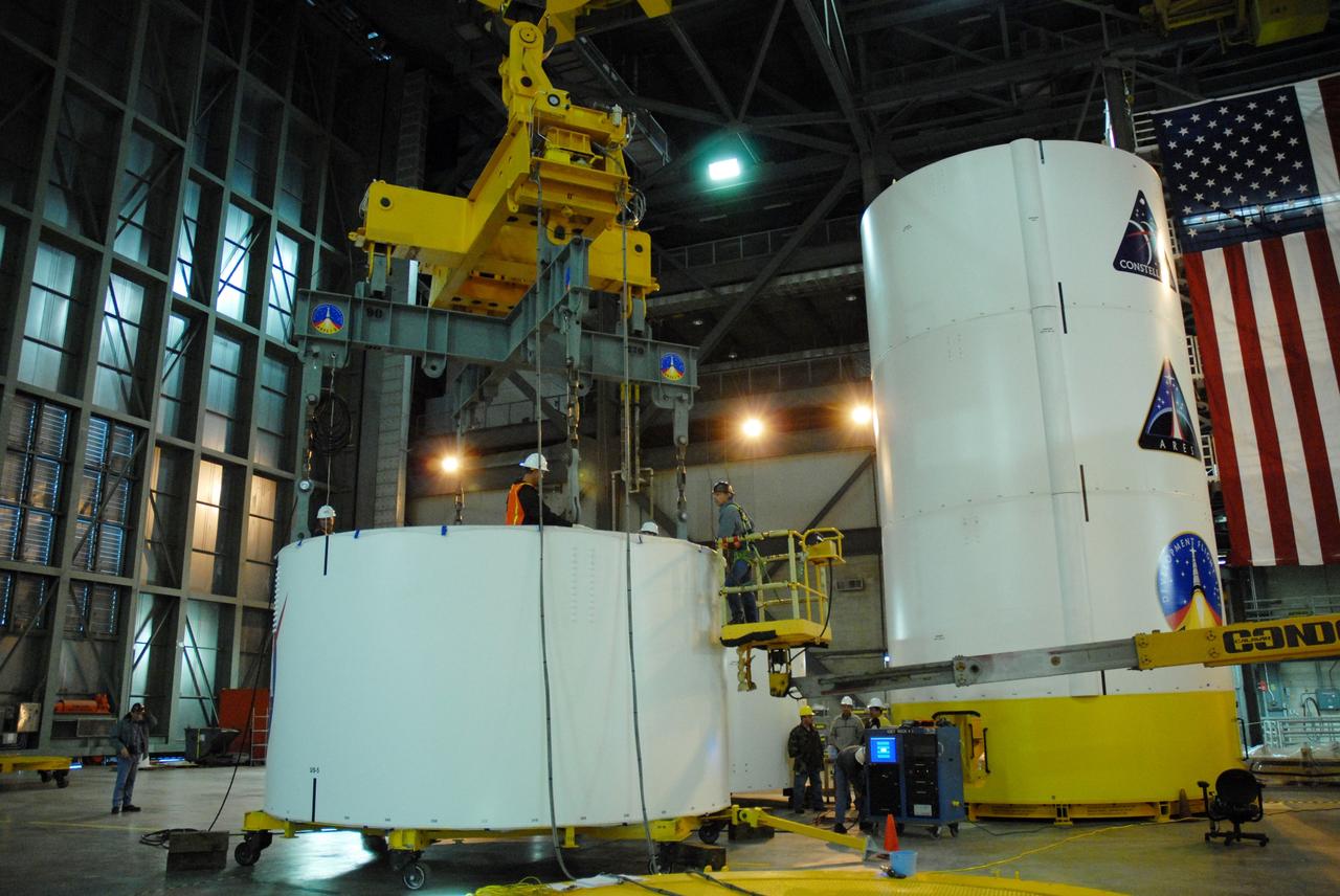
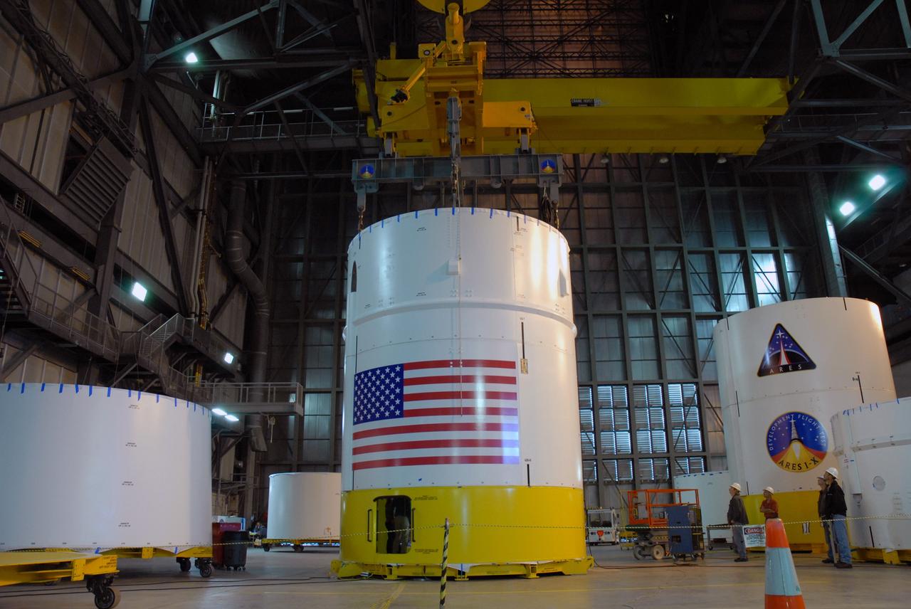
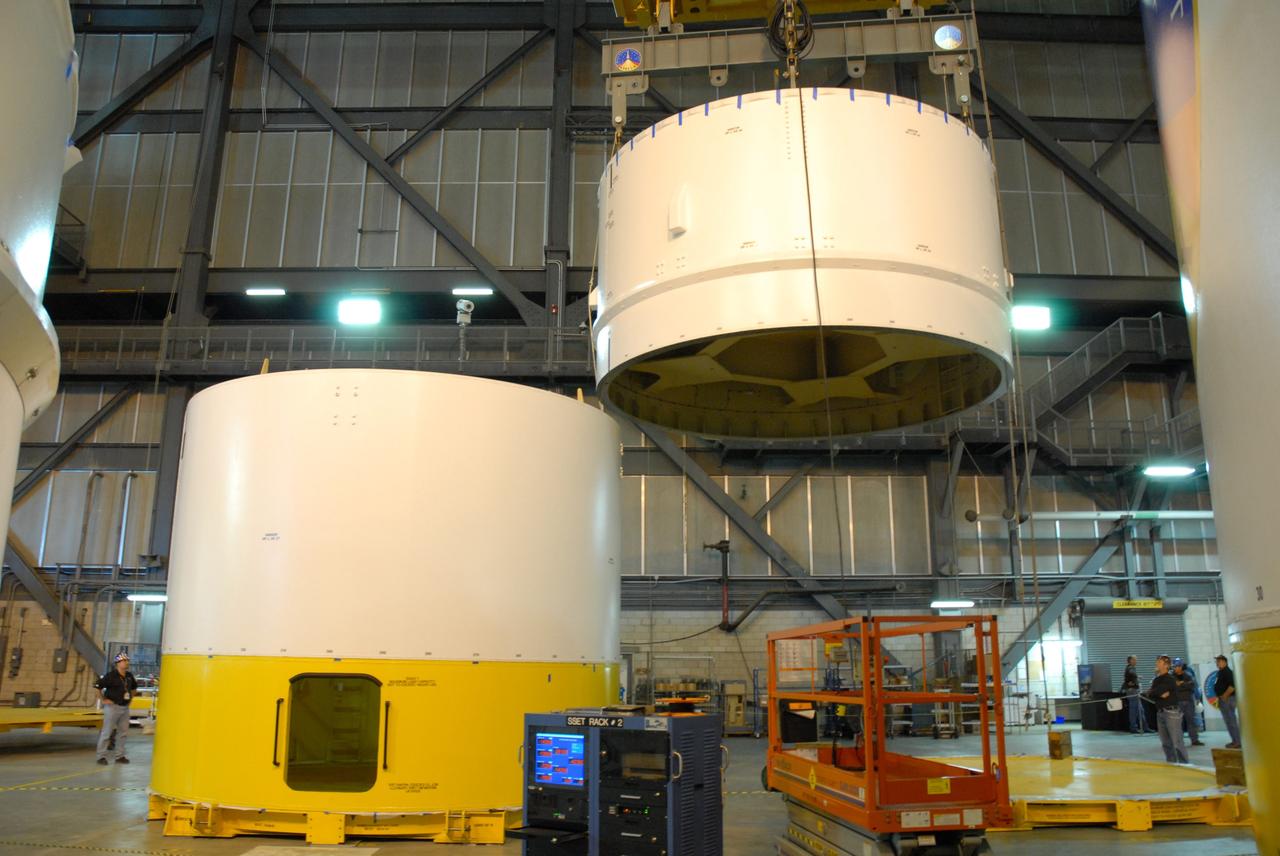
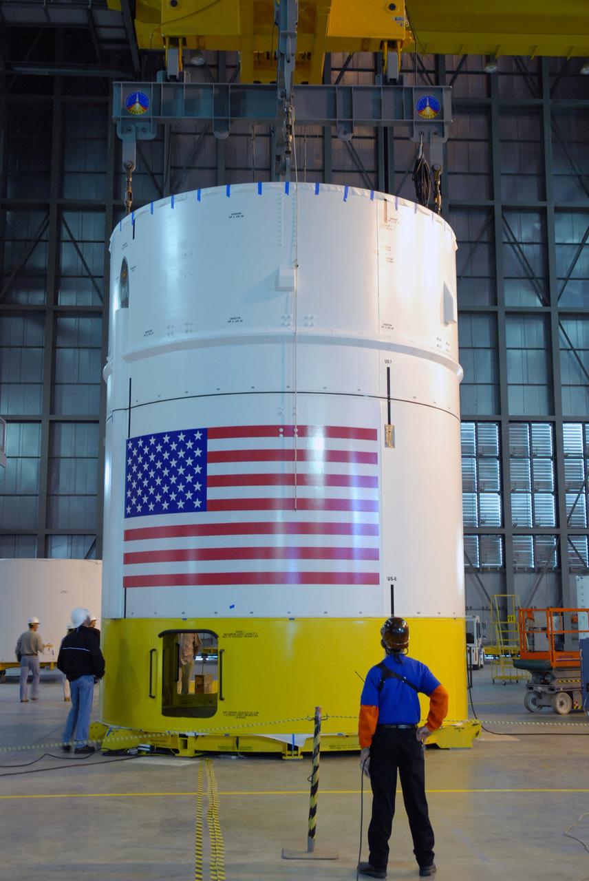
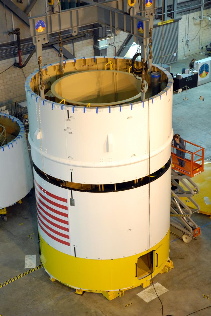
CAPE CANAVERAL, Fla. -- In high bay 4 of the Vehicle Assembly Building at NASA's Kennedy Space Center in Florida, a crane moves the Ares I-X upper stage simulator segment 7 toward segment 6 (in front, with U.S. flag decal). The upper stage simulator comprises 11 segments, each approximately 18 feet in diameter, that will be used in the test flight identified as Ares I-X in 2009. The simulator segments will simulate the mass and the outer mold line. The upper stage accounts for nearly one-quarter of the total height of the Ares I. It will take the Ares I on the second phase of its journey from Earth, providing the guidance, navigation and control needed for the second phase of the Ares I ascent flight. Photo credit: NASA/Kim Shiflett
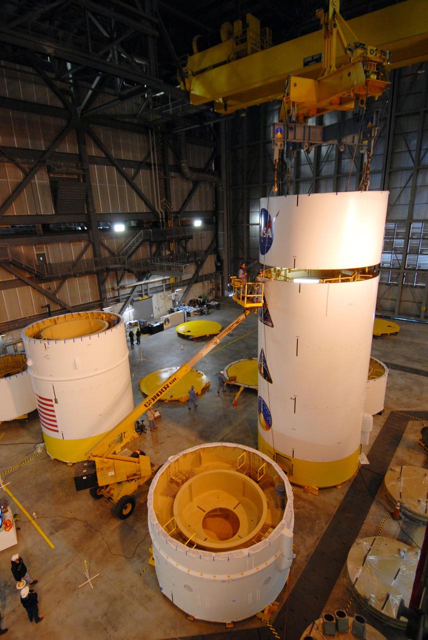
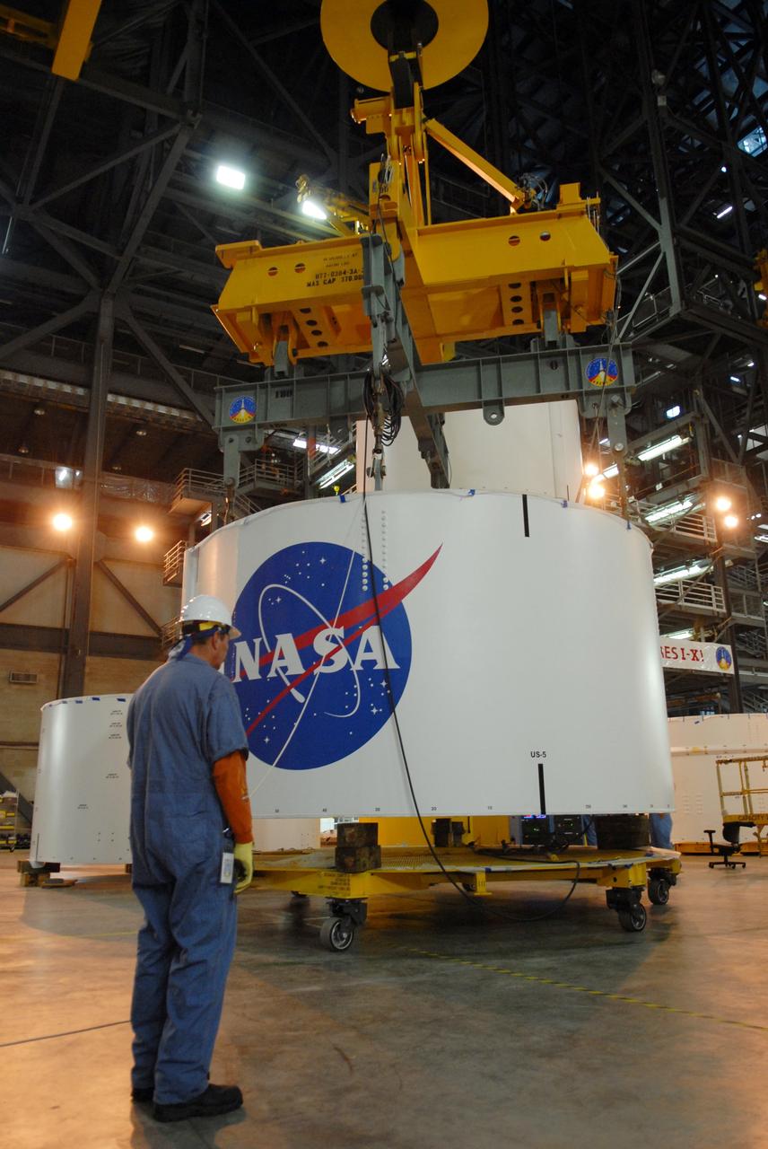
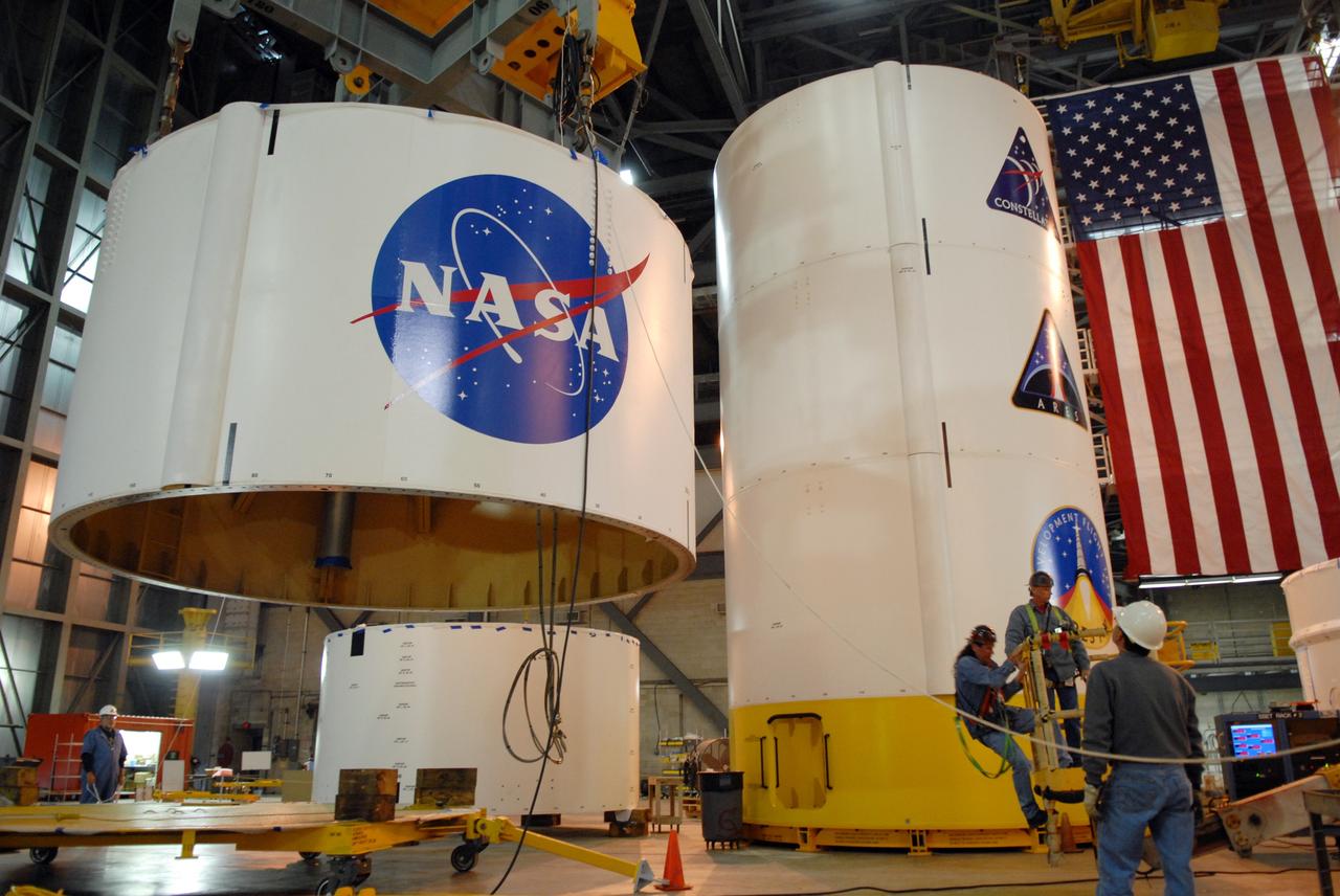
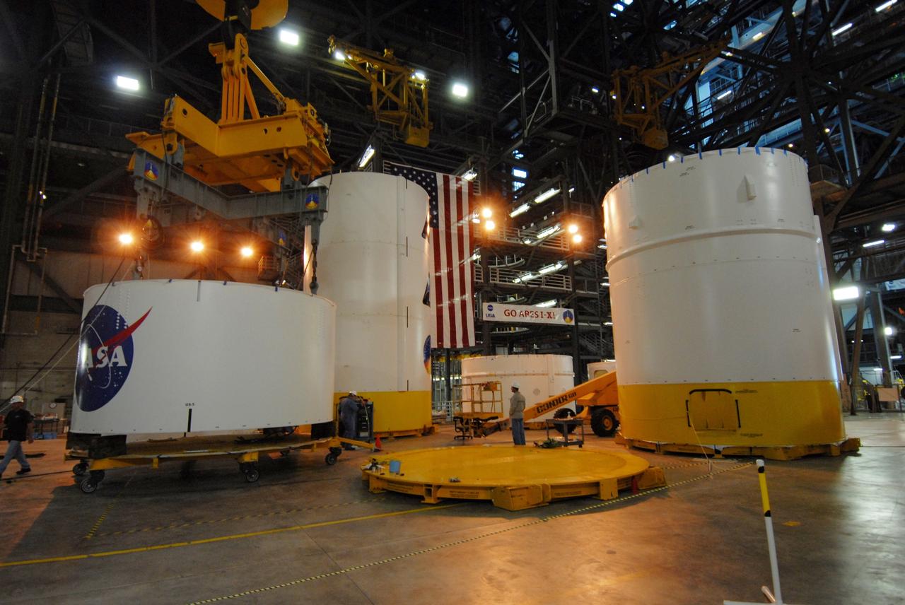
CAPE CANAVERAL, Fla. -- In high bay 4 of the Vehicle Assembly Building at NASA's Kennedy Space Center in Florida, a crane is attached to segment 5 of the Ares I-X upper stage simulator segments to lift it. Segment 5 will be stacked on to segment 4, at the top of the tall stack at right.The upper stage simulator comprises 11 segments, each approximately 18 feet in diameter, that will be used in the test flight known as Ares I-X in 2009. The simulator segments will simulate the mass and the outer mold line. The upper stage accounts for nearly one-quarter of the total height of the Ares I. It will take the Ares I on the second phase of its journey from Earth, providing the guidance, navigation and control needed for the second phase of the Ares I ascent flight. Photo credit: NASA/Jim Grossmann
CAPE CANAVERAL, Fla. -- In high bay 4 of the Vehicle Assembly Building at NASA's Kennedy Space Center in Florida, a crane lowers segment 5 of the Ares I-X upper stage simulator segments onto segment 4, at top of the tall stack below. The upper stage simulator comprises 11 segments, each approximately 18 feet in diameter, that will be used in the test flight known as Ares I-X in 2009. The simulator segments will simulate the mass and the outer mold line. The upper stage accounts for nearly one-quarter of the total height of the Ares I. It will take the Ares I on the second phase of its journey from Earth, providing the guidance, navigation and control needed for the second phase of the Ares I ascent flight. Photo credit: NASA/Troy Cryder
CAPE CANAVERAL, Fla. -- In high bay 4 of the Vehicle Assembly Building at NASA's Kennedy Space Center in Florida, the Ares I-X upper stage simulator segment 7 is stacked onto segment 6. The upper stage simulator comprises 11 segments, each approximately 18 feet in diameter, that will be used in the test flight identified as Ares I-X in 2009. The simulator segments will simulate the mass and the outer mold line. The upper stage accounts for nearly one-quarter of the total height of the Ares I. It will take the Ares I on the second phase of its journey from Earth, providing the guidance, navigation and control needed for the second phase of the Ares I ascent flight. Photo credit: NASA/Kim Shiflett
CAPE CANAVERAL, Fla. -- In high bay 4 of the Vehicle Assembly Building at NASA's Kennedy Space Center in Florida, work is under way to stack the Ares I-X upper stage simulator segment 5 to segment 4. The upper stage simulator comprises 11 segments, each approximately 18 feet in diameter, that will be used in the test flight known as Ares I-X in 2009. The simulator segments will simulate the mass and the outer mold line. The upper stage accounts for nearly one-quarter of the total height of the Ares I. It will take the Ares I on the second phase of its journey from Earth, providing the guidance, navigation and control needed for the second phase of the Ares I ascent flight. Photo credit: NASA/Jim Grossmann
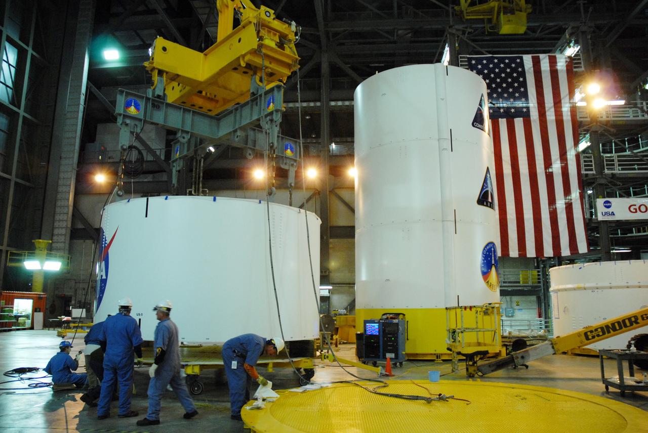
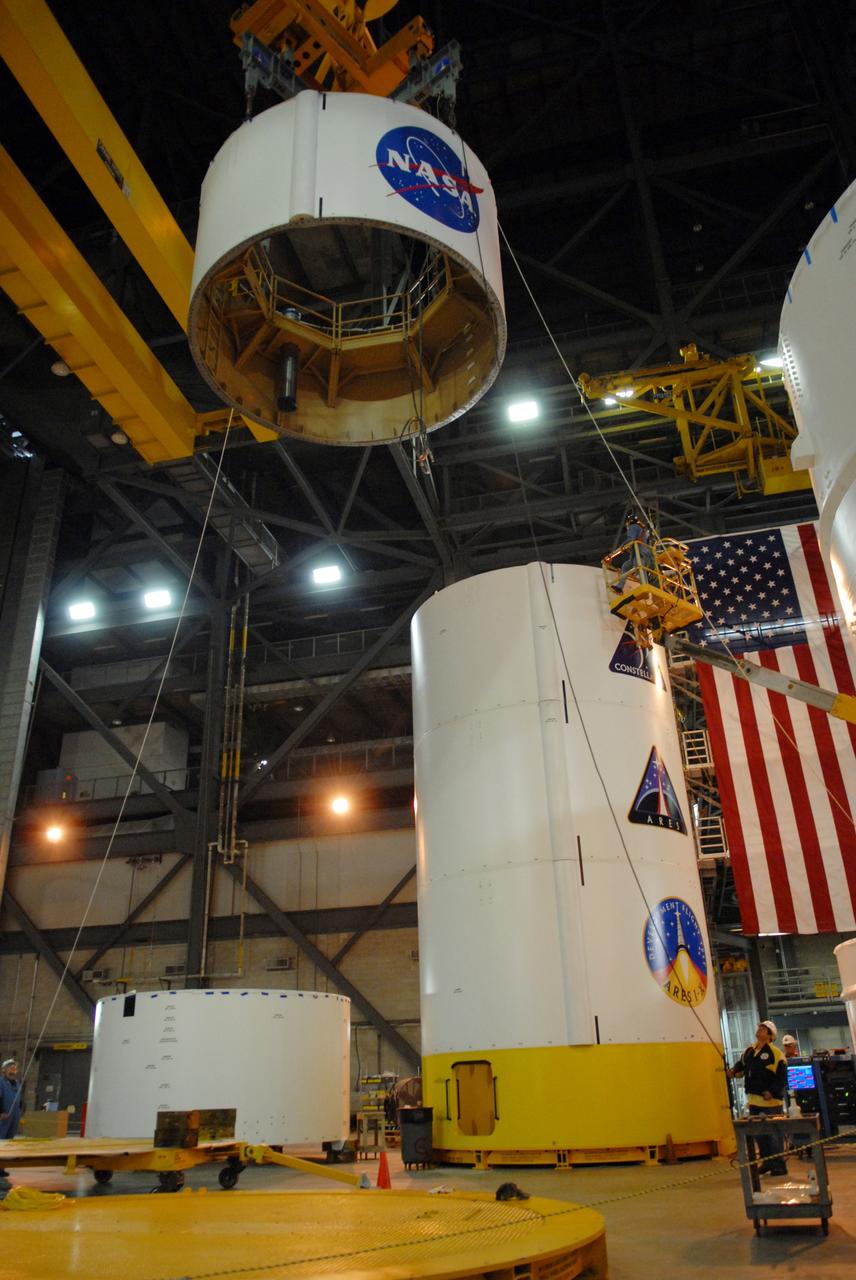
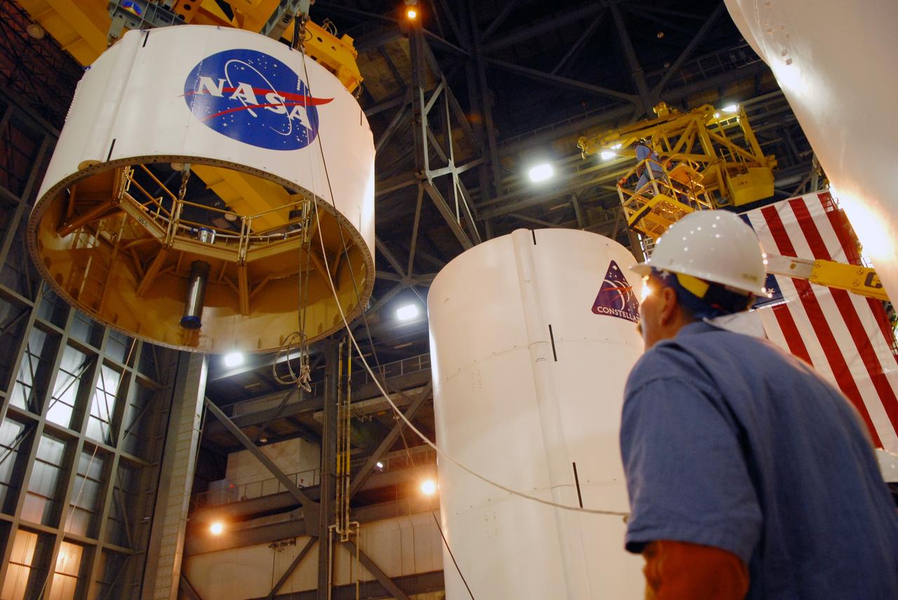
CAPE CANAVERAL, Fla. -- In high bay 4 of the Vehicle Assembly Building at NASA's Kennedy Space Center in Florida, a crane lifts segment 5 of the Ares I-X upper stage simulator segments. It will be placed on segment 4, at top of the tall stack behind it.The upper stage simulator comprises 11 segments, each approximately 18 feet in diameter, that will be used in the test flight known as Ares I-X in 2009. The simulator segments will simulate the mass and the outer mold line. The upper stage accounts for nearly one-quarter of the total height of the Ares I. It will take the Ares I on the second phase of its journey from Earth, providing the guidance, navigation and control needed for the second phase of the Ares I ascent flight. Photo credit: NASA/Troy Cryder
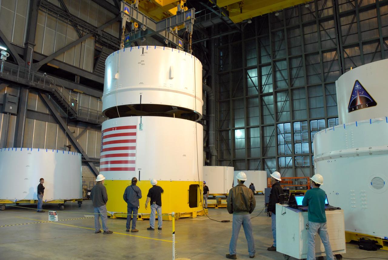
CAPE CANAVERAL, Fla. -- In high bay 4 of the Vehicle Assembly Building at NASA's Kennedy Space Center in Florida, a crane lowers the Ares I-X upper stage simulator segment 7 toward segment 6. The upper stage simulator comprises 11 segments, each approximately 18 feet in diameter, that will be used in the test flight identified as Ares I-X in 2009. The simulator segments will simulate the mass and the outer mold line. The upper stage accounts for nearly one-quarter of the total height of the Ares I. It will take the Ares I on the second phase of its journey from Earth, providing the guidance, navigation and control needed for the second phase of the Ares I ascent flight. Photo credit: NASA/Kim Shiflett
CAPE CANAVERAL, Fla. -- In high bay 4 of the Vehicle Assembly Building at NASA's Kennedy Space Center in Florida, a crane is attached to segment 5 of the Ares I-X upper stage simulator segments to lift it. Segment 5 will be stacked on to segment 4, at the top of the tall stack at right. The upper stage simulator comprises 11 segments, each approximately 18 feet in diameter, that will be used in the test flight known as Ares I-X in 2009. The simulator segments will simulate the mass and the outer mold line. The upper stage accounts for nearly one-quarter of the total height of the Ares I. It will take the Ares I on the second phase of its journey from Earth, providing the guidance, navigation and control needed for the second phase of the Ares I ascent flight. Photo credit: NASA/Jim Grossmann
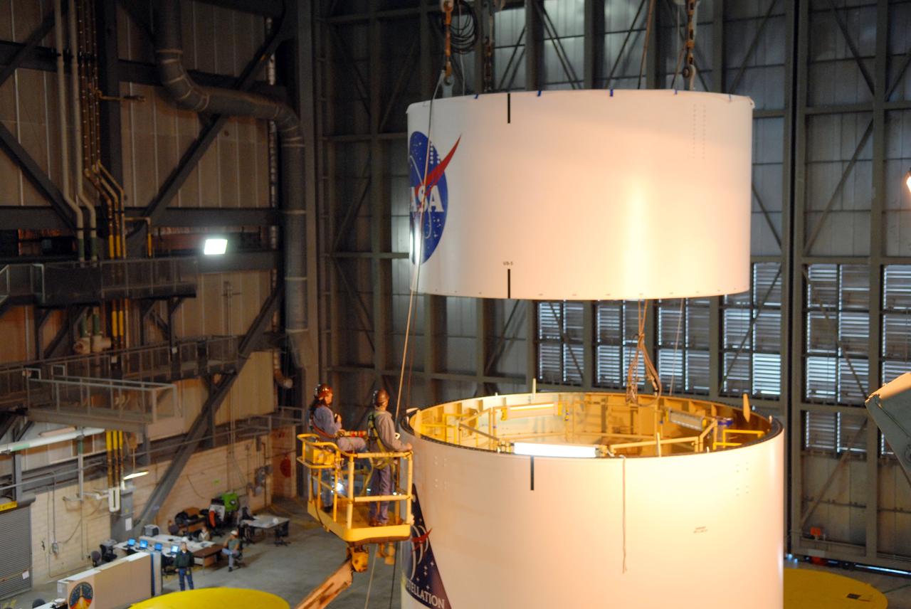
CAPE CANAVERAL, Fla. -- In high bay 4 of the Vehicle Assembly Building at NASA's Kennedy Space Center in Florida, a crane lowers segment 5 of the Ares I-X upper stage simulator segments toward segment 4, at top of the tall stack below. The upper stage simulator comprises 11 segments, each approximately 18 feet in diameter, that will be used in the test flight known as Ares I-X in 2009. The simulator segments will simulate the mass and the outer mold line. The upper stage accounts for nearly one-quarter of the total height of the Ares I. It will take the Ares I on the second phase of its journey from Earth, providing the guidance, navigation and control needed for the second phase of the Ares I ascent flight. Photo credit: NASA/Troy Cryder

CAPE CANAVERAL, Fla. -- In high bay 4 of the Vehicle Assembly Building at NASA's Kennedy Space Center in Florida, a crane is ready to lift the Ares I-X upper stage simulator segment 7. The segment will be stacked onto segment 6. The upper stage simulator comprises 11 segments, each approximately 18 feet in diameter, that will be used in the test flight identified as Ares I-X in 2009. The simulator segments will simulate the mass and the outer mold line. The upper stage accounts for nearly one-quarter of the total height of the Ares I. It will take the Ares I on the second phase of its journey from Earth, providing the guidance, navigation and control needed for the second phase of the Ares I ascent flight. Photo credit: NASA/Kim Shiflett
CAPE CANAVERAL, Fla. -- In high bay 4 of the Vehicle Assembly Building at NASA's Kennedy Space Center in Florida, a crane lifts the Ares I-X upper stage simulator segment 7. The segment will be stacked onto segment 6. The upper stage simulator comprises 11 segments, each approximately 18 feet in diameter, that will be used in the test flight identified as Ares I-X in 2009. The simulator segments will simulate the mass and the outer mold line. The upper stage accounts for nearly one-quarter of the total height of the Ares I. It will take the Ares I on the second phase of its journey from Earth, providing the guidance, navigation and control needed for the second phase of the Ares I ascent flight. Photo credit: NASA/Kim Shiflett
CAPE CANAVERAL, Fla. -- In high bay 4 of the Vehicle Assembly Building at NASA's Kennedy Space Center in Florida, a crane lifts segment 5 of the Ares I-X upper stage simulator segments. It will be placed on segment 4, at top of the tall stack behind it. The upper stage simulator comprises 11 segments, each approximately 18 feet in diameter, that will be used in the test flight known as Ares I-X in 2009. The simulator segments will simulate the mass and the outer mold line. The upper stage accounts for nearly one-quarter of the total height of the Ares I. It will take the Ares I on the second phase of its journey from Earth, providing the guidance, navigation and control needed for the second phase of the Ares I ascent flight. Photo credit: NASA/Troy Cryder
CAPE CANAVERAL, Fla. -- In high bay 4 of the Vehicle Assembly Building at NASA's Kennedy Space Center in Florida, a crane lowers the Ares I-X upper stage simulator segment 7 onto segment 6. The upper stage simulator comprises 11 segments, each approximately 18 feet in diameter, that will be used in the test flight identified as Ares I-X in 2009. The simulator segments will simulate the mass and the outer mold line. The upper stage accounts for nearly one-quarter of the total height of the Ares I. It will take the Ares I on the second phase of its journey from Earth, providing the guidance, navigation and control needed for the second phase of the Ares I ascent flight. Photo credit: NASA/Kim Shiflett
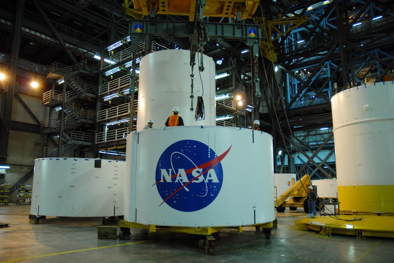
CAPE CANAVERAL, Fla. -- In high bay 4 of the Vehicle Assembly Building at NASA's Kennedy Space Center in Florida, a crane moves segment 5 of the Ares I-X upper stage simulator segments toward the tall stack behind it. Segment 5 will be placed on segment 4, at top of the tall stack. The upper stage simulator comprises 11 segments, each approximately 18 feet in diameter, that will be used in the test flight known as Ares I-X in 2009. The simulator segments will simulate the mass and the outer mold line. The upper stage accounts for nearly one-quarter of the total height of the Ares I. It will take the Ares I on the second phase of its journey from Earth, providing the guidance, navigation and control needed for the second phase of the Ares I ascent flight. Photo credit: NASA/Troy Cryder
CAPE CANAVERAL, Fla. -- In high bay 4 of the Vehicle Assembly Building at NASA's Kennedy Space Center in Florida, a crane lowers the Ares I-X upper stage simulator segment 7 onto segment 6. The upper stage simulator comprises 11 segments, each approximately 18 feet in diameter, that will be used in the test flight identified as Ares I-X in 2009. The simulator segments will simulate the mass and the outer mold line. The upper stage accounts for nearly one-quarter of the total height of the Ares I. It will take the Ares I on the second phase of its journey from Earth, providing the guidance, navigation and control needed for the second phase of the Ares I ascent flight. Photo credit: NASA/Kim Shiflett
CAPE CANAVERAL, Fla. -- In high bay 4 of the Vehicle Assembly Building at NASA's Kennedy Space Center in Florida, a crane lifts segment 5 of the Ares I-X upper stage simulator segments. It will be placed on segment 4, at top of the tall stack behind it. The upper stage simulator comprises 11 segments, each approximately 18 feet in diameter, that will be used in the test flight known as Ares I-X in 2009. The simulator segments will simulate the mass and the outer mold line. The upper stage accounts for nearly one-quarter of the total height of the Ares I. It will take the Ares I on the second phase of its journey from Earth, providing the guidance, navigation and control needed for the second phase of the Ares I ascent flight. Photo credit: NASA/Troy Cryder
CAPE CANAVERAL, Fla. -- In high bay 4 of the Vehicle Assembly Building at NASA's Kennedy Space Center in Florida, a crane lifts segment 5 of the Ares I-X upper stage simulator segments toward the tall stack behind it. Segment 5 will be placed on segment 4, at top of the tall stack. The upper stage simulator comprises 11 segments, each approximately 18 feet in diameter, that will be used in the test flight known as Ares I-X in 2009. The simulator segments will simulate the mass and the outer mold line. The upper stage accounts for nearly one-quarter of the total height of the Ares I. It will take the Ares I on the second phase of its journey from Earth, providing the guidance, navigation and control needed for the second phase of the Ares I ascent flight. Photo credit: NASA/Troy Cryder
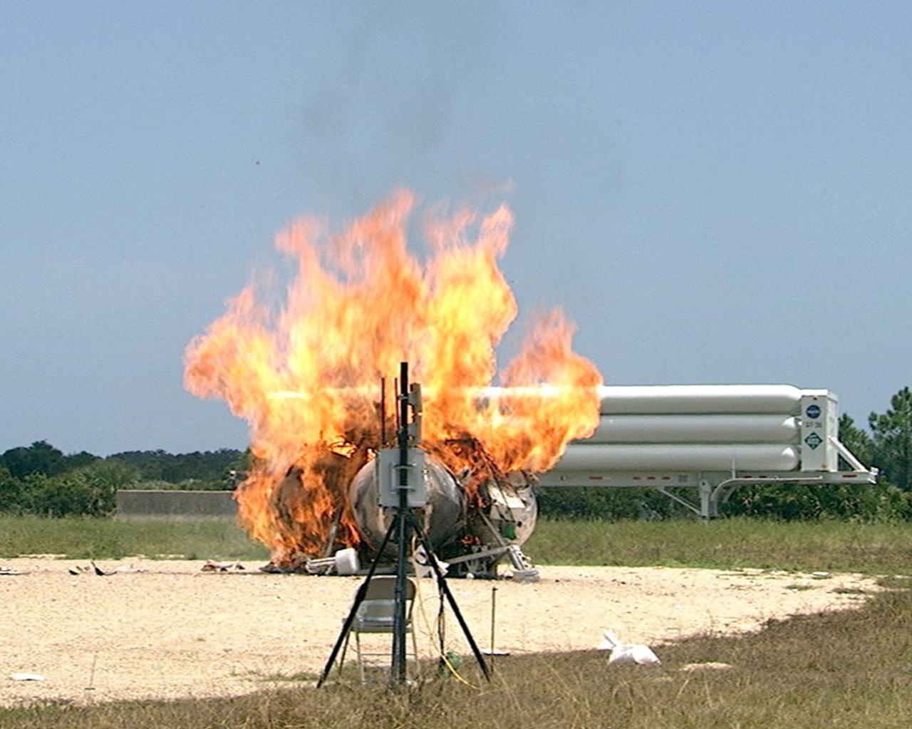
CAPE CANAVERAL, Fla. – During a free-flight test of the Project Morpheus vehicle at the Shuttle Landing Facility at NASA’s Kennedy Space Center in Florida, the vehicle lifted off the ground and then experienced a hardware component failure, which prevented it from maintaining stable flight. No one was injured and the resulting fire was extinguished by Kennedy fire personnel. Engineers are looking into the test data and the agency will release information as it becomes available. Failures such as these were anticipated prior to the test, and are part of the development process for any complex spaceflight hardware. Testing of the prototype lander had been ongoing at NASA’s Johnson Space Center in Houston in preparation for its first free-flight test at Kennedy Space Center. Morpheus was manufactured and assembled at JSC and Armadillo Aerospace. Morpheus is large enough to carry 1,100 pounds of cargo to the moon – for example, a humanoid robot, a small rover, or a small laboratory to convert moon dust into oxygen. The primary focus of the test is to demonstrate an integrated propulsion and guidance, navigation and control system that can fly a lunar descent profile to exercise the Autonomous Landing and Hazard Avoidance Technology, or ALHAT, safe landing sensors and closed-loop flight control. For more information on Project Morpheus, visit http://morpheuslander.jsc.nasa.gov/. Photo credit: NASA
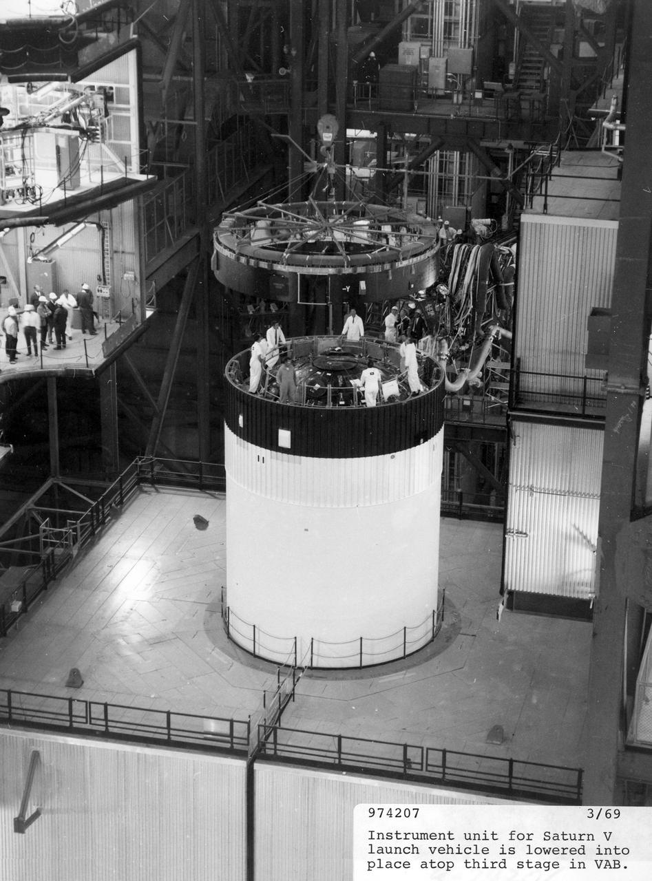
The instrument unit for the Saturn V launch vehicle, AS-506, used to propel the Apollo 11 lunar landing mission, is lowered into place atop the third (S-IVB) stage in the vehicle assembly building at the NASA Kennedy Space Center (KSC). Designed by the NASA Marshall Space Flight Center (MSFC), the instrument unit served as the Saturn’s “nerve center” providing guidance and control, command and sequence of vehicle functions, telemetry, and environmental control. The Apollo 11 mission launched from KSC in Florida via the MSFC developed Saturn V launch vehicle on July 16, 1969 and safely returned to Earth on July 24, 1969. Astronauts onboard included Neil A. Armstrong, commander; Michael Collins, Command Module (CM) pilot; and Edwin E. Aldrin, Jr., Lunar Module (LM) pilot. The CM, “Columbia”, piloted by Collins, remained in a parking orbit around the Moon while the LM, “Eagle’’, carrying astronauts Armstrong and Aldrin, landed on the Moon. On July 20, 1969, Armstrong was the first human to ever stand on the lunar surface, followed by Aldrin. During 2½ hours of surface exploration, the crew collected 47 pounds of lunar surface material for analysis back on Earth. With the success of Apollo 11, the national objective to land men on the Moon and return them safely to Earth had been accomplished
CAPE CANAVERAL, Fla. – During a free-flight test of the Project Morpheus vehicle at the Shuttle Landing Facility at NASA’s Kennedy Space Center in Florida, the vehicle lifted off the ground and then experienced a hardware component failure, which prevented it from maintaining stable flight. Engineers are looking into the test data and the agency will release information as it becomes available. Failures such as these were anticipated prior to the test, and are part of the development process for any complex spaceflight hardware. Testing of the prototype lander had been ongoing at NASA’s Johnson Space Center in Houston in preparation for its first free-flight test at Kennedy Space Center. Morpheus was manufactured and assembled at JSC and Armadillo Aerospace. Morpheus is large enough to carry 1,100 pounds of cargo to the moon – for example, a humanoid robot, a small rover, or a small laboratory to convert moon dust into oxygen. The primary focus of the test is to demonstrate an integrated propulsion and guidance, navigation and control system that can fly a lunar descent profile to exercise the Autonomous Landing and Hazard Avoidance Technology, or ALHAT, safe landing sensors and closed-loop flight control. For more information on Project Morpheus, visit http://morpheuslander.jsc.nasa.gov/. Photo credit: NASA
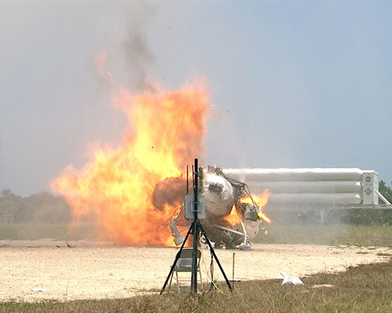
CAPE CANAVERAL, Fla. – During a free-flight test of the Project Morpheus vehicle at the Shuttle Landing Facility at NASA’s Kennedy Space Center in Florida, the vehicle lifted off the ground and then experienced a hardware component failure, which prevented it from maintaining stable flight. No one was injured and the resulting fire was extinguished by Kennedy fire personnel. Engineers are looking into the test data and the agency will release information as it becomes available. Failures such as these were anticipated prior to the test, and are part of the development process for any complex spaceflight hardware. Testing of the prototype lander had been ongoing at NASA’s Johnson Space Center in Houston in preparation for its first free-flight test at Kennedy Space Center. Morpheus was manufactured and assembled at JSC and Armadillo Aerospace. Morpheus is large enough to carry 1,100 pounds of cargo to the moon – for example, a humanoid robot, a small rover, or a small laboratory to convert moon dust into oxygen. The primary focus of the test is to demonstrate an integrated propulsion and guidance, navigation and control system that can fly a lunar descent profile to exercise the Autonomous Landing and Hazard Avoidance Technology, or ALHAT, safe landing sensors and closed-loop flight control. For more information on Project Morpheus, visit http://morpheuslander.jsc.nasa.gov/. Photo credit: NASA
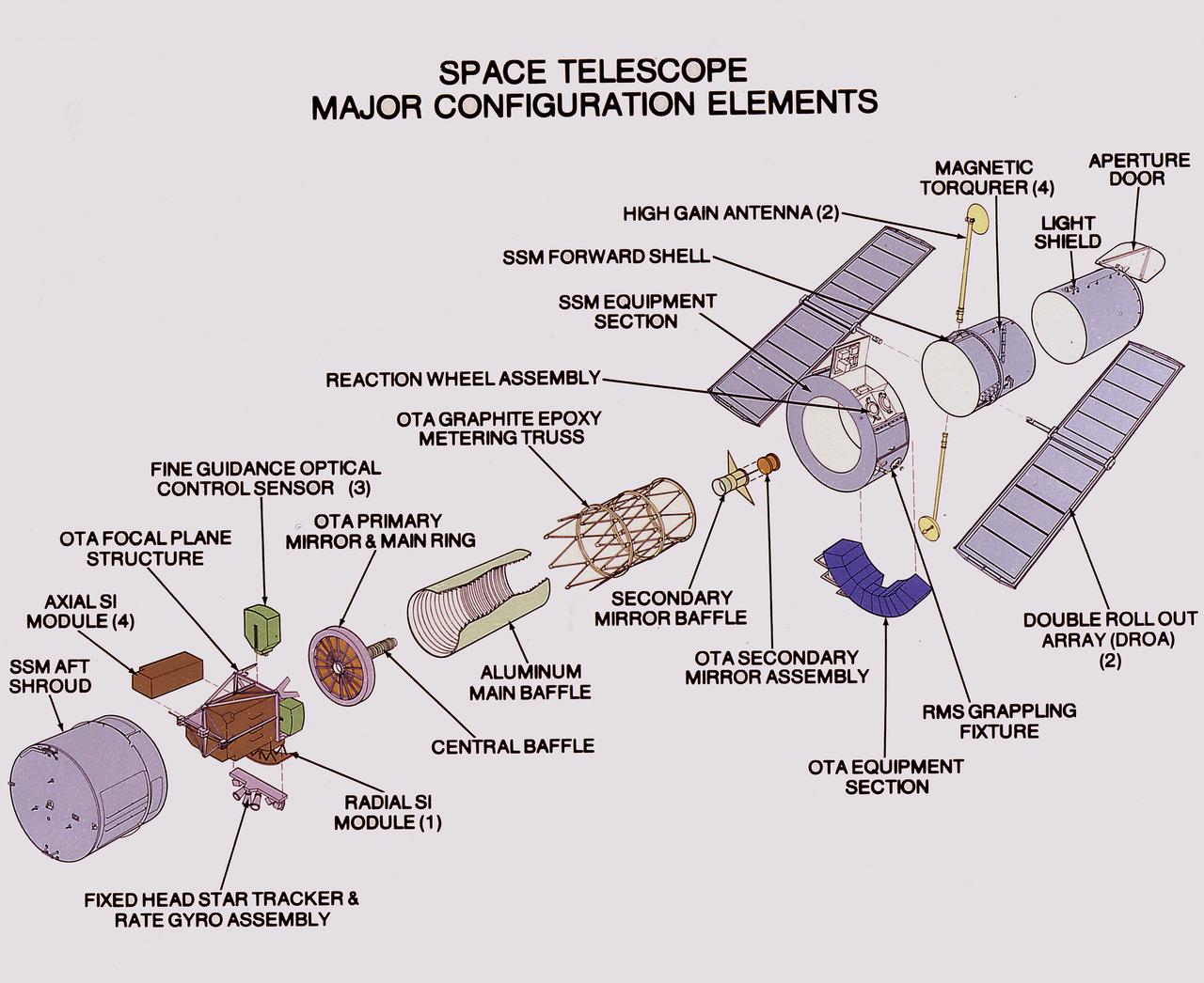
This illustration shows the Hubble Space Telescope's (HST's) major configuration elements. The spacecraft has three interacting systems: The Support System Module (SSM), an outer structure that houses the other systems and provides services such as power, communication, and control; The Optical Telescope Assembly (OTA), which collects and concentrates the incoming light in the focal plane for use by the Scientific Instruments (SI); and five SIs. The SI Control and Data Handling (CDH) unit controls the five SI's, four that are housed in an aft section focal plane structure and one that is placed along the circumference of the spacecraft. The purpose of the HST, the most complex and sensitive optical telescope ever made, is to study the cosmos from a low-Earth orbit. By placing the telescope in space, astronomers are able to collect data that is free of the Earth's atmosphere. The HST detects objects 25 times fainter than the dimmest objects seen from Earth and provides astronomers with an observable universe 250 times larger than visible from ground-based telescopes, perhaps as far away as 14 billion light-years. The HST views galaxies, stars, planets, comets, possibly other solar systems, and even unusual phenomena such as quasars, with 10 times the clarity of ground-based telescopes. The HST was deployed from the Space Shuttle Discovery (STS-31 mission) into Earth orbit in April 1990. The Marshall Space Flight Center had responsibility for design, development, and construction of the HST. The Perkin-Elmer Corporation, in Danbury, Cornecticut, developed the optical system and guidance sensors. The Lockheed Missile and Space Company of Sunnyvale, California produced the protective outer shroud and spacecraft systems, and assembled and tested the finished telescope.
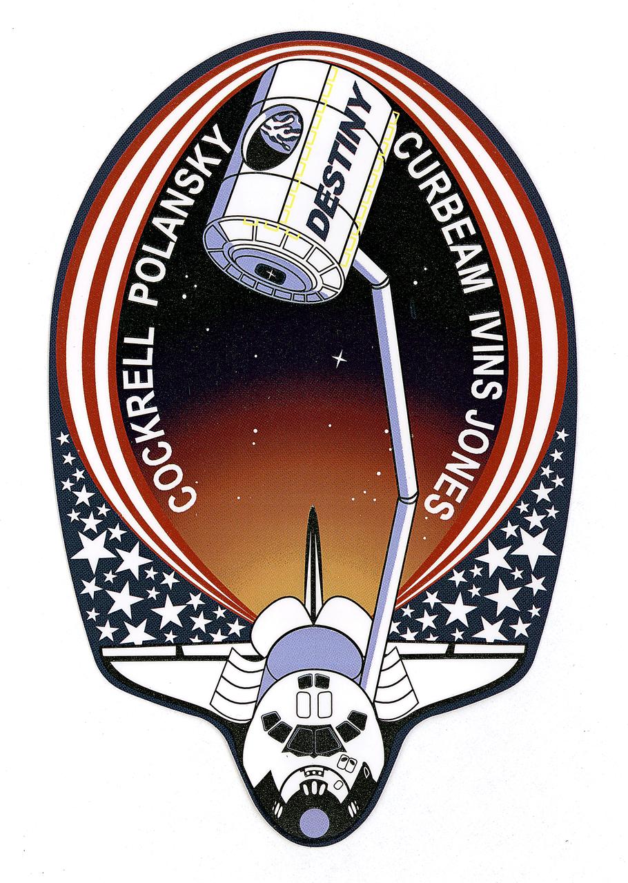
This is the insignia for STS-98, which marks a major milestone in assembly of the International Space Station (ISS). Atlantis' crew delivered the United States Laboratory, Destiny, to the ISS. Destiny will be the centerpiece of the ISS, a weightless laboratory where expedition crews will perform unprecedented research in the life sciences, materials sciences, Earth sciences, and microgravity sciences. The laboratory is also the nerve center of the Station, performing guidance, control, power distribution, and life support functions. With Destiny's arrival, the Station will begin to fulfill its promise of returning the benefits of space research to Earth's citizens. The crew patch depicts the Space Shuttle with Destiny held high above the payload bay just before its attachment to the ISS. Red and white stripes, with a deep blue field of white stars, border the Shuttle and Destiny to symbolize the continuing contribution of the United States to the ISS. The constellation Hercules, seen just below Destiny, captures the Shuttle and Station's team efforts in bringing the promise of orbital scientific research to life. The reflection of Earth in Destiny's window emphasizes the connection between space exploration and life on Earth.
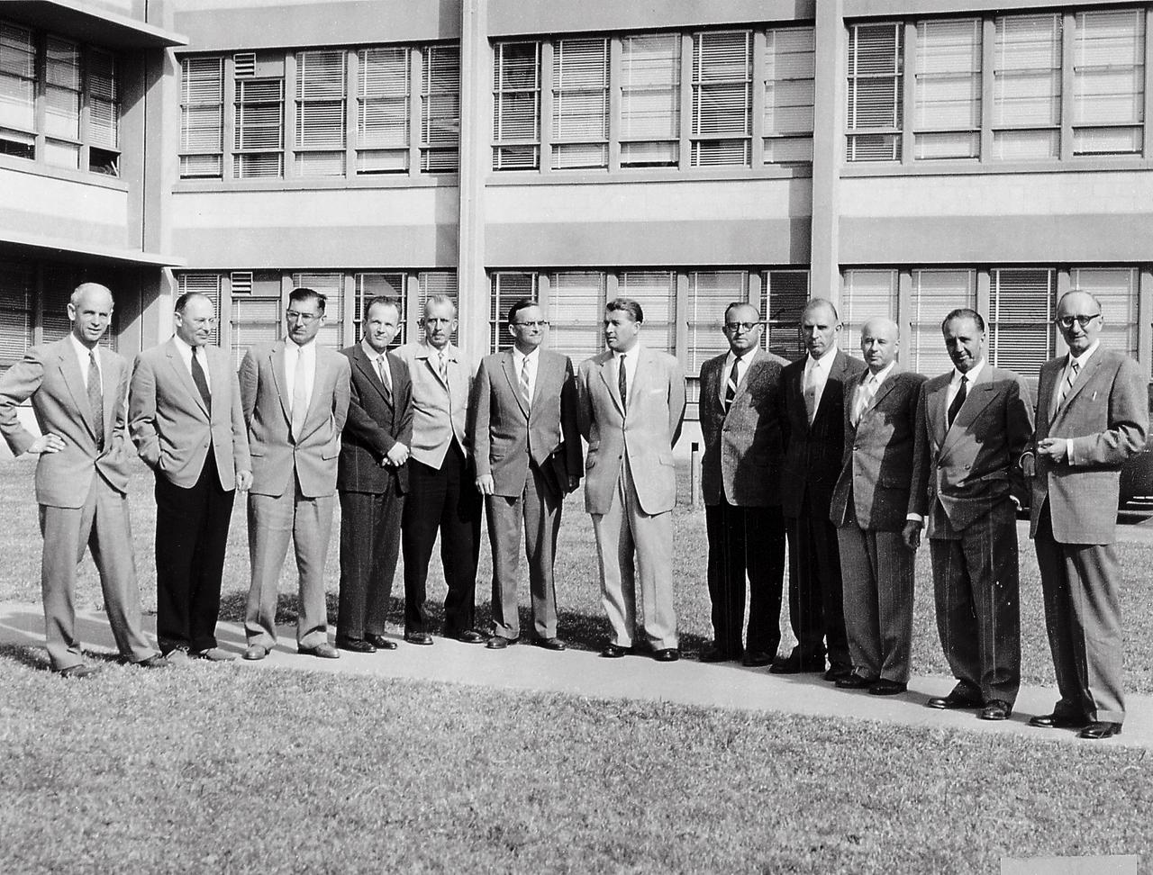
Twelve scientific specialists of the Peenemuende team at the front of Building 4488, Redstone Arsenal, Huntsville, Alabama. They led the Army's space efforts at ABMA before transfer of the team to National Aeronautic and Space Administration (NASA), George C. Marshall Space Flight Center (MSFC). (Left to right) Dr. Ernst Stuhlinger, Director, Research Projects Office; Dr. Helmut Hoelzer, Director, Computation Laboratory: Karl L. Heimburg, Director, Test Laboratory; Dr. Ernst Geissler, Director, Aeroballistics Laboratory; Erich W. Neubert, Director, Systems Analysis Reliability Laboratory; Dr. Walter Haeussermarn, Director, Guidance and Control Laboratory; Dr. Wernher von Braun, Director Development Operations Division; William A. Mrazek, Director, Structures and Mechanics Laboratory; Hans Hueter, Director, System Support Equipment Laboratory;Eberhard Rees, Deputy Director, Development Operations Division; Dr. Kurt Debus, Director Missile Firing Laboratory; Hans H. Maus, Director, Fabrication and Assembly Engineering Laboratory
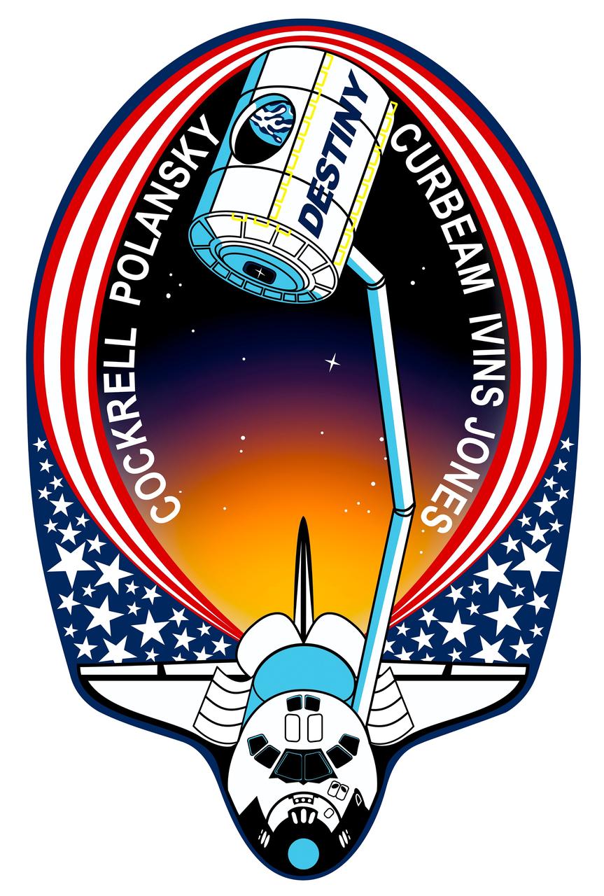
STS098-S-001 (November 2000) --- This is the insignia for STS-98, which marks a major milestone in assembly of the International Space Station (ISS). Atlantis' crew will deliver the United States Laboratory, Destiny, to the ISS. Destiny will be the centerpiece of the ISS, a weightless laboratory where expedition crews will perform unprecedented research in the life sciences, materials sciences, Earth sciences, and microgravity sciences. The laboratory is also the nerve center of the station, performing guidance, control, power distribution, and life support functions. With Destiny's arrival, the station will begin to fulfill its promise of returning the benefits of space research to Earth's citizens. The crew patch depicts the space shuttle with Destiny held high above the payload bay just before its attachment to the ISS. Red and white stripes, with a deep blue field of white stars, border the shuttle and Destiny to symbolize the continuing contribution of the United States to the ISS. The constellation Hercules, seen just below Destiny, captures the shuttle and station's team efforts in bringing the promise of orbital scientific research to life. The reflection of Earth in Destiny's window emphasizes the connection between space exploration and life on Earth. The NASA insignia design for space shuttle flights is reserved for use by the astronauts and for other official use as the NASA Administrator may authorize. Public availability has been approved only in the forms of illustrations by the various news media. When and if there is any change in this policy, which is not anticipated, the change will be publicly announced. Photo credit: NASA