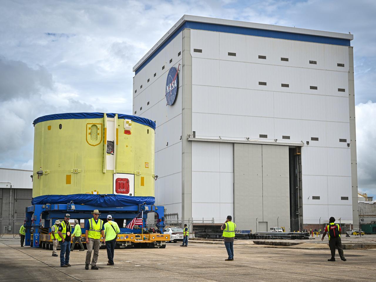
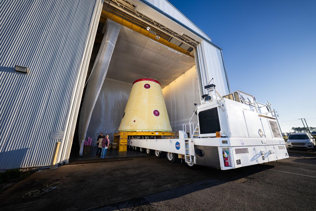
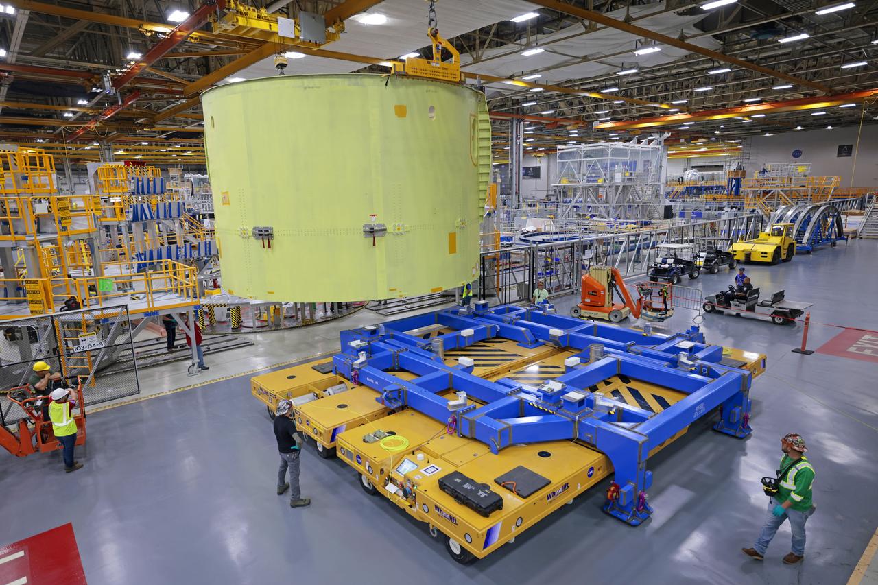
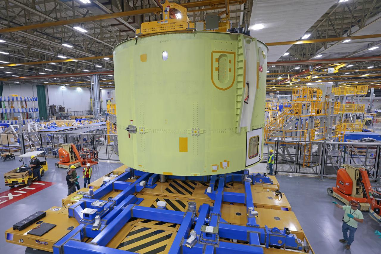
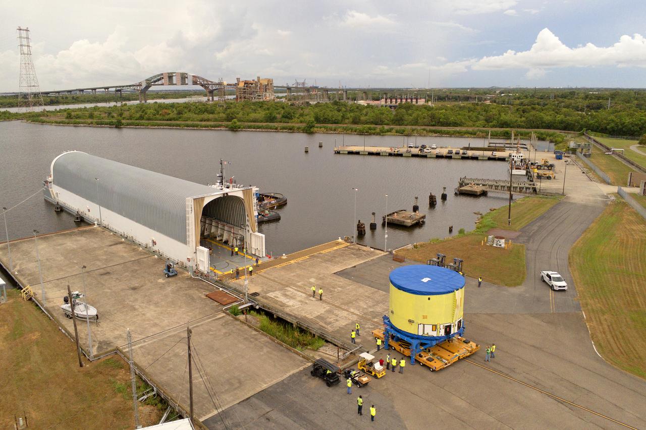
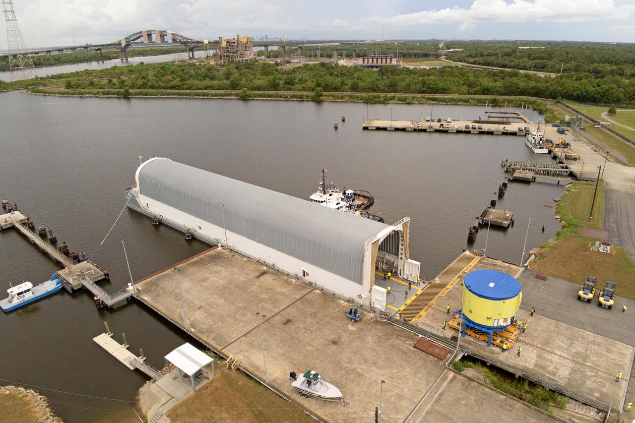
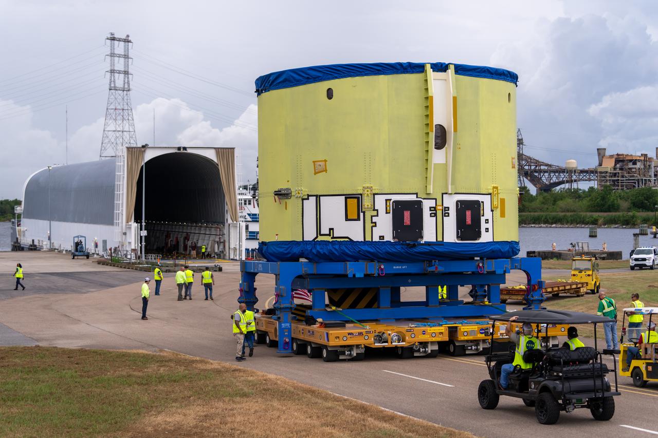
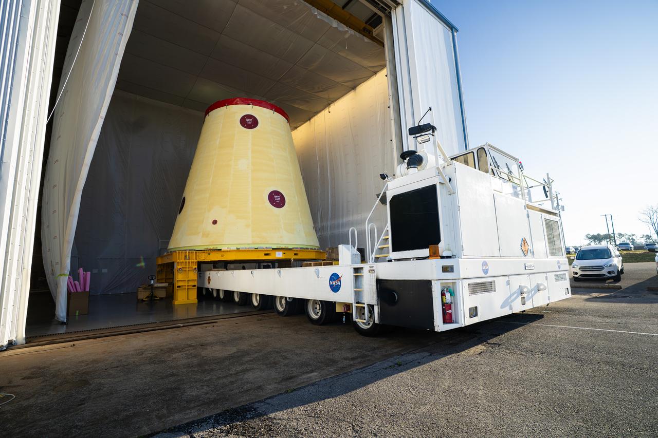
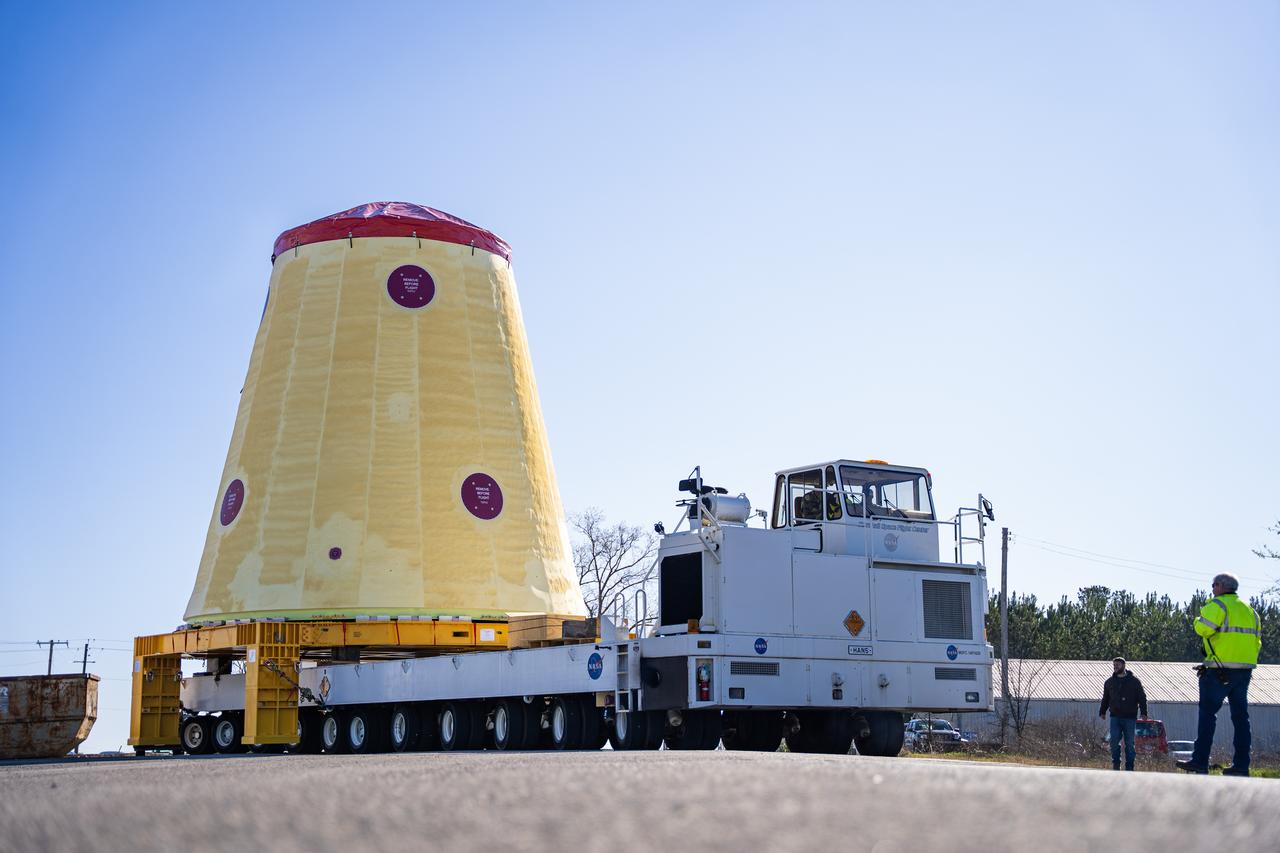
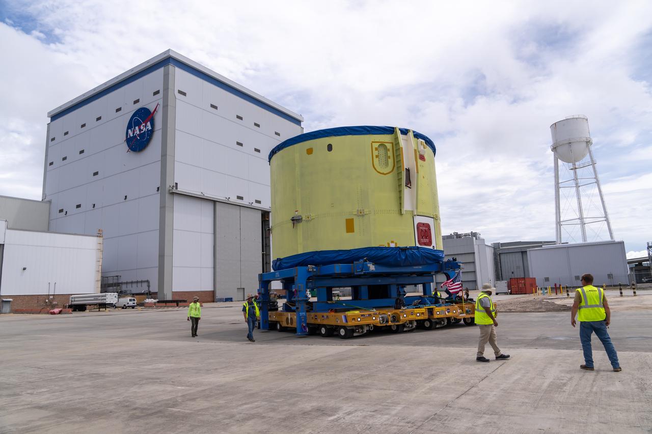
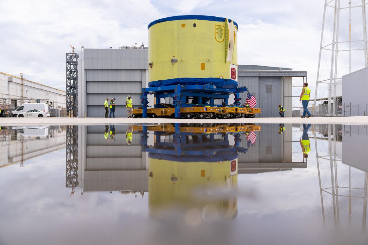
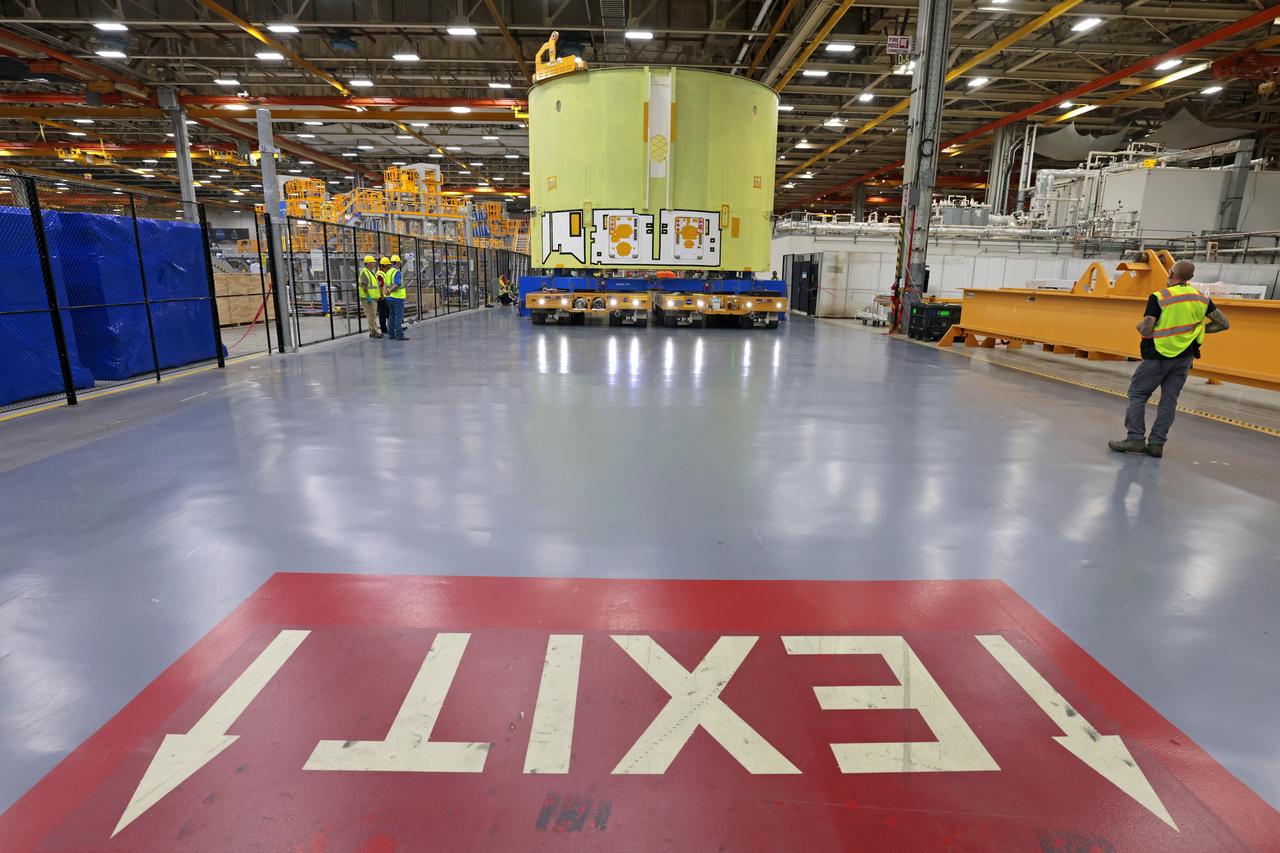
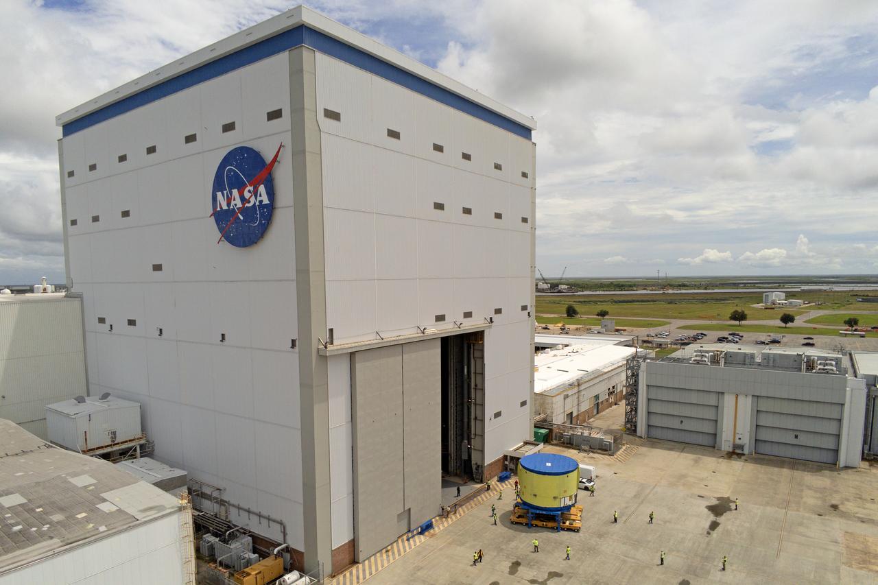
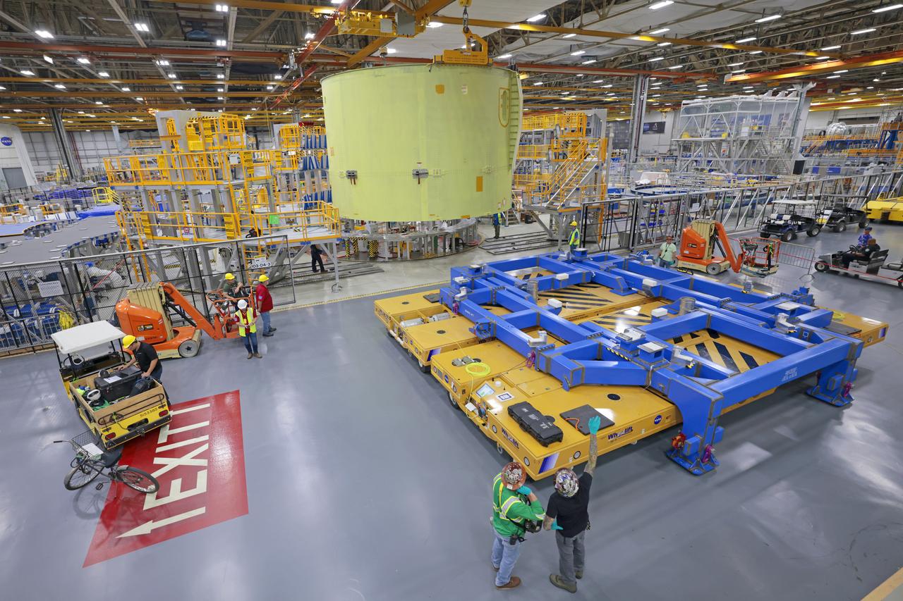
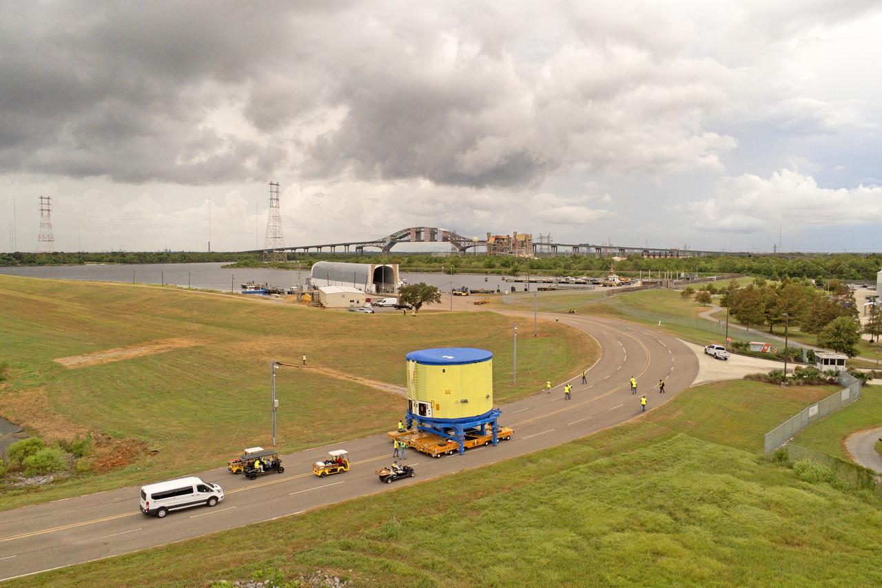
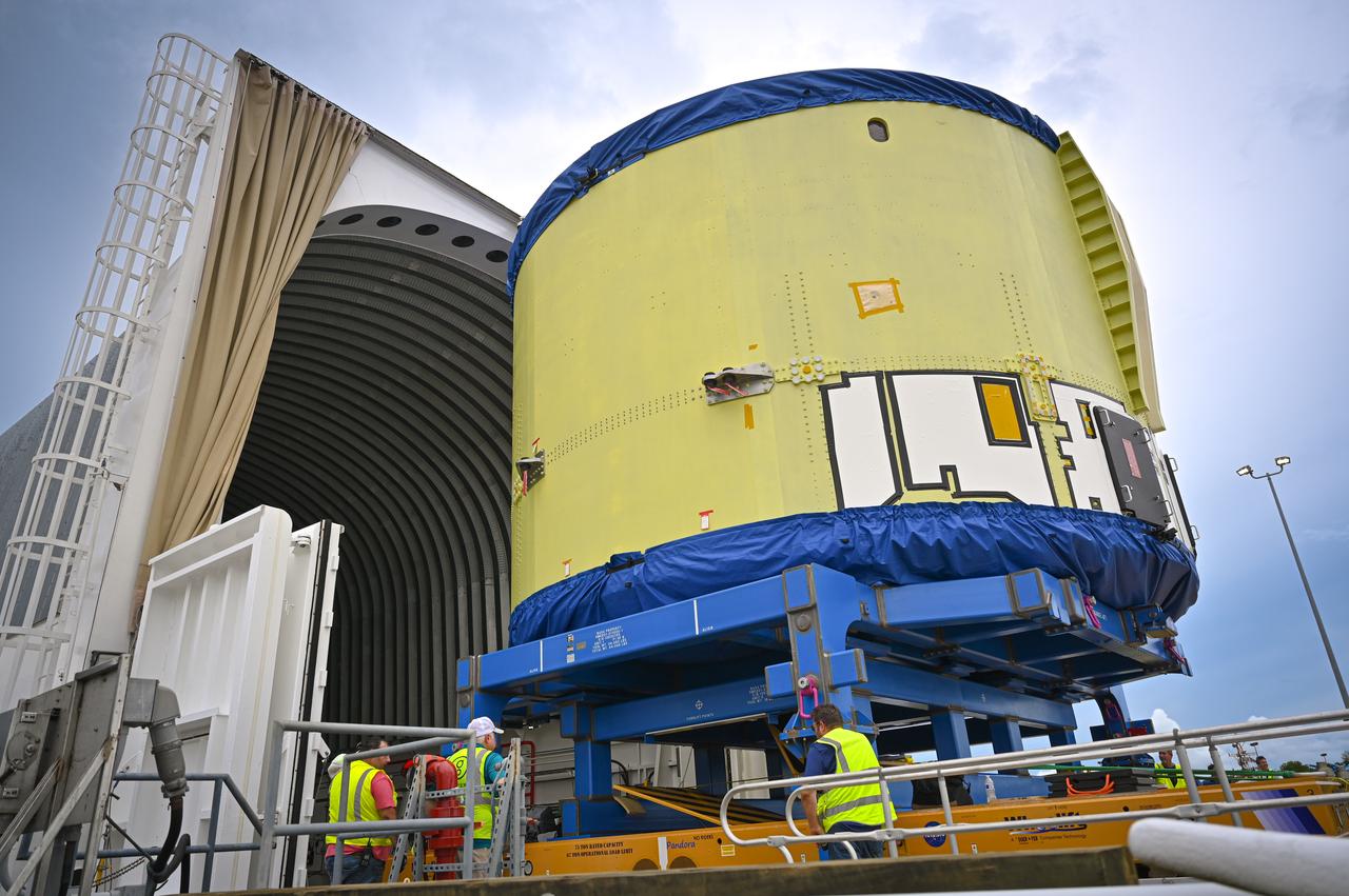
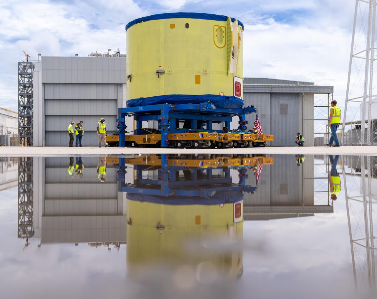
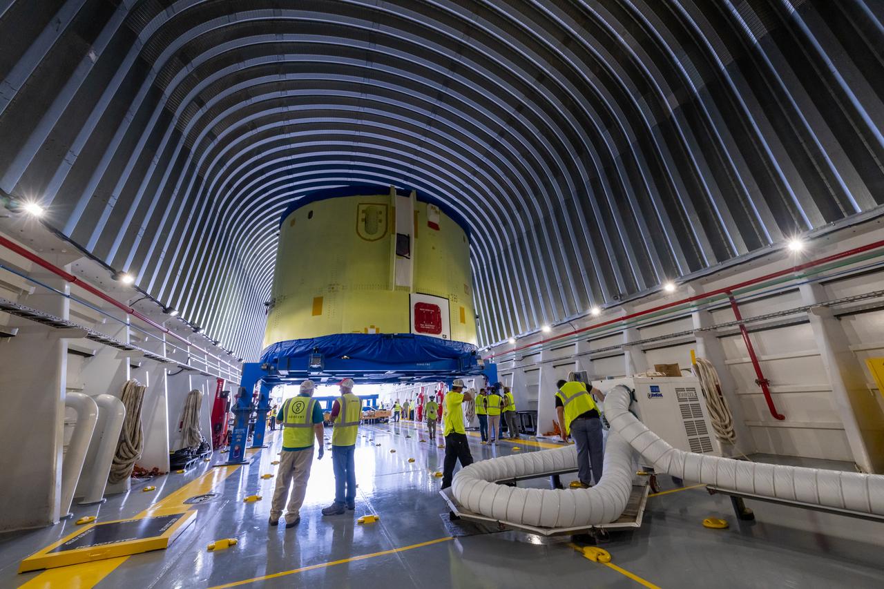
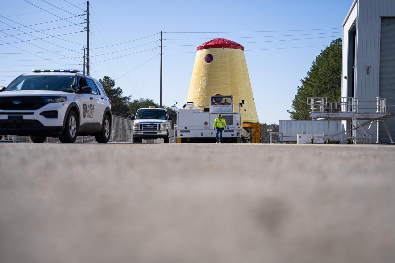
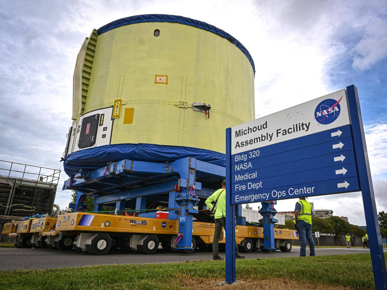
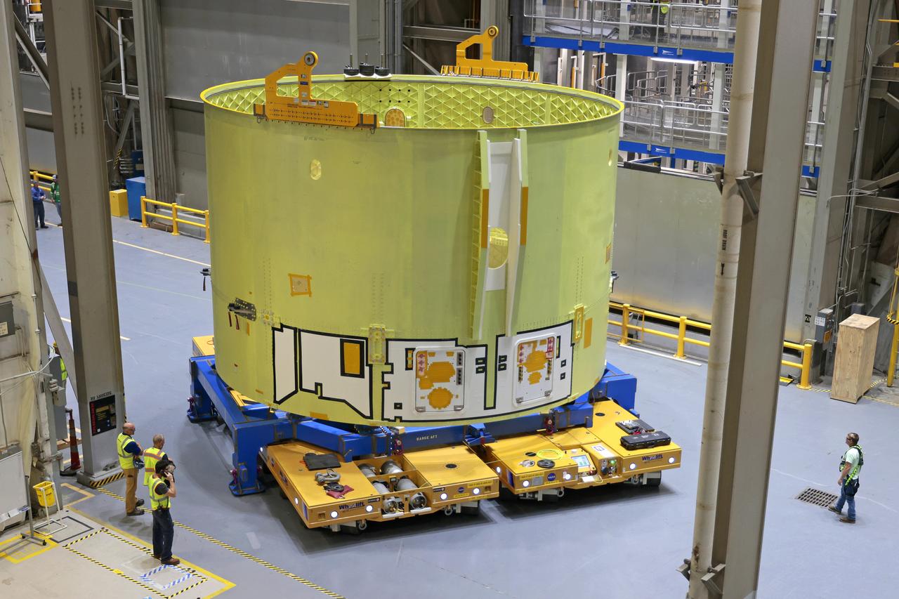
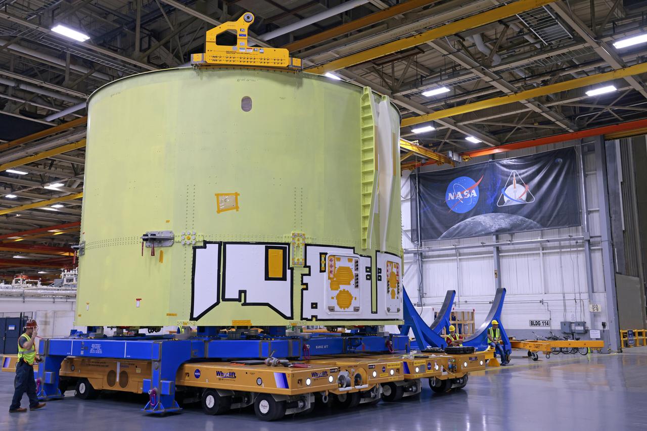
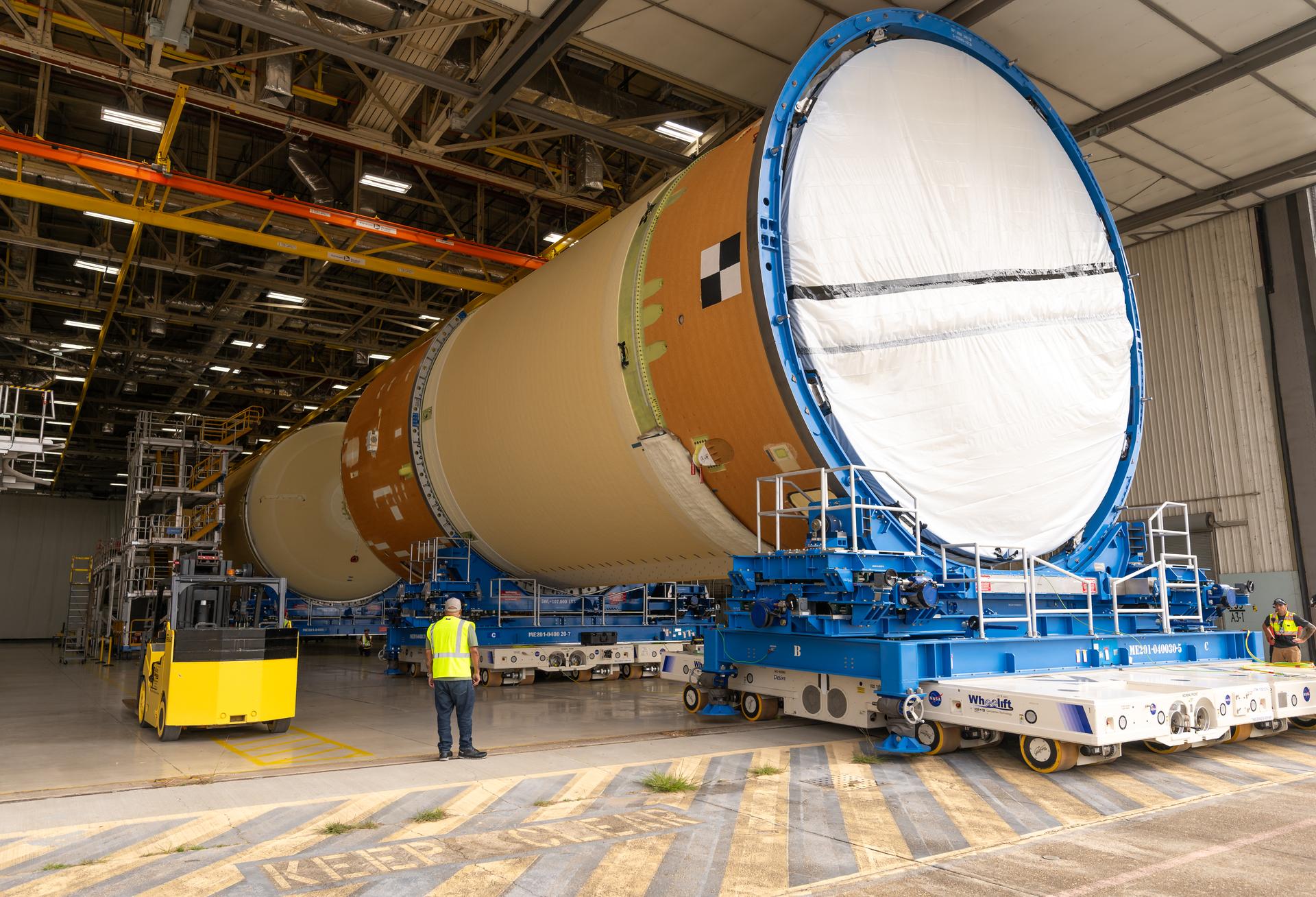
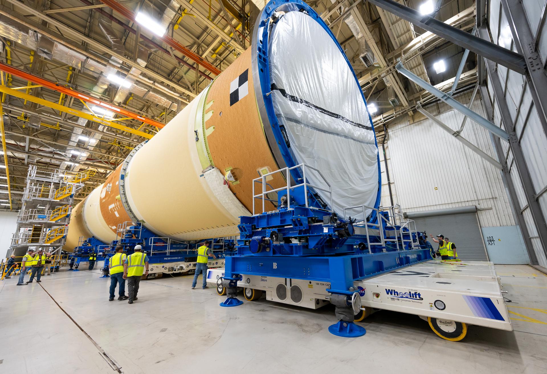
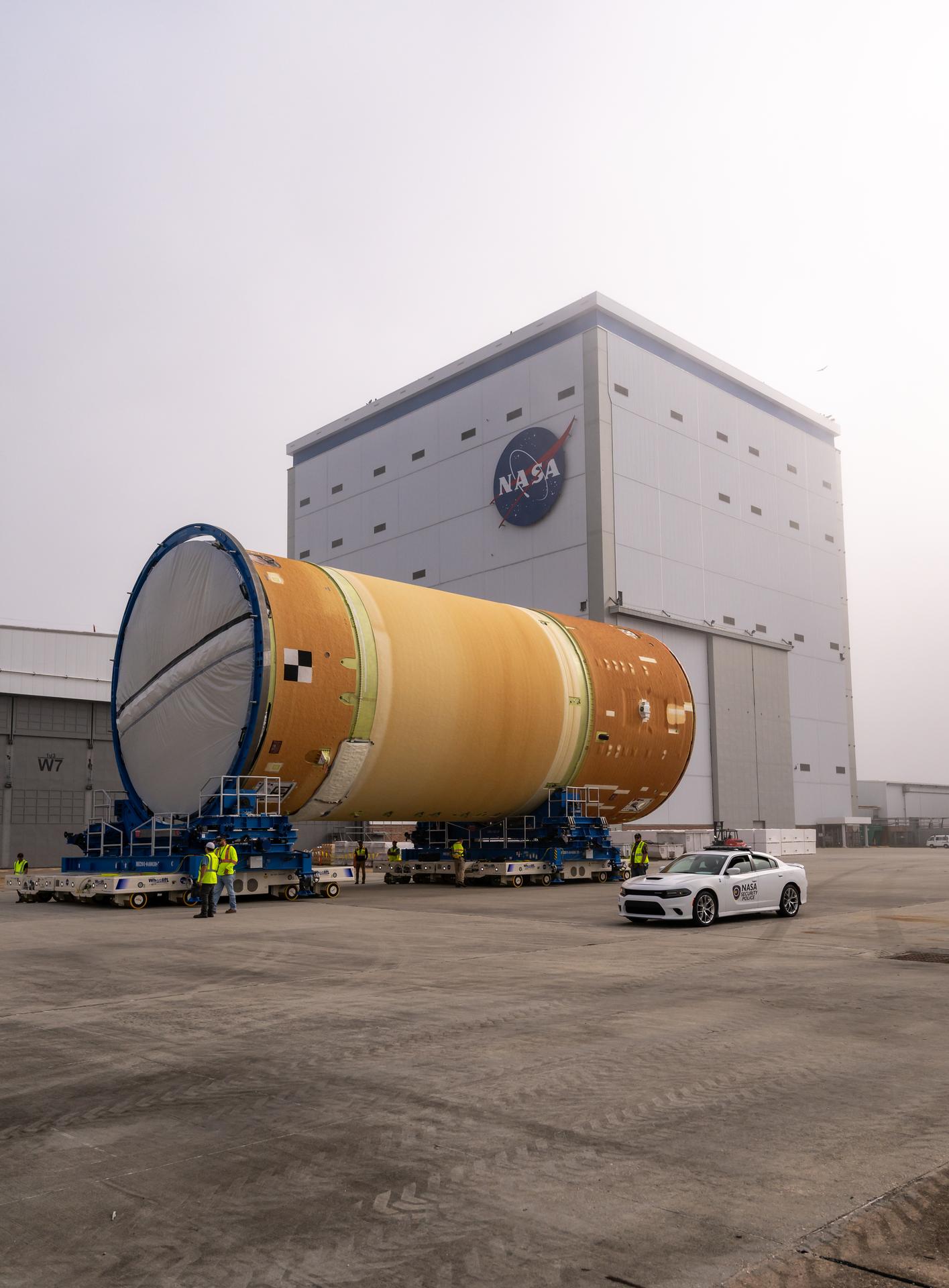
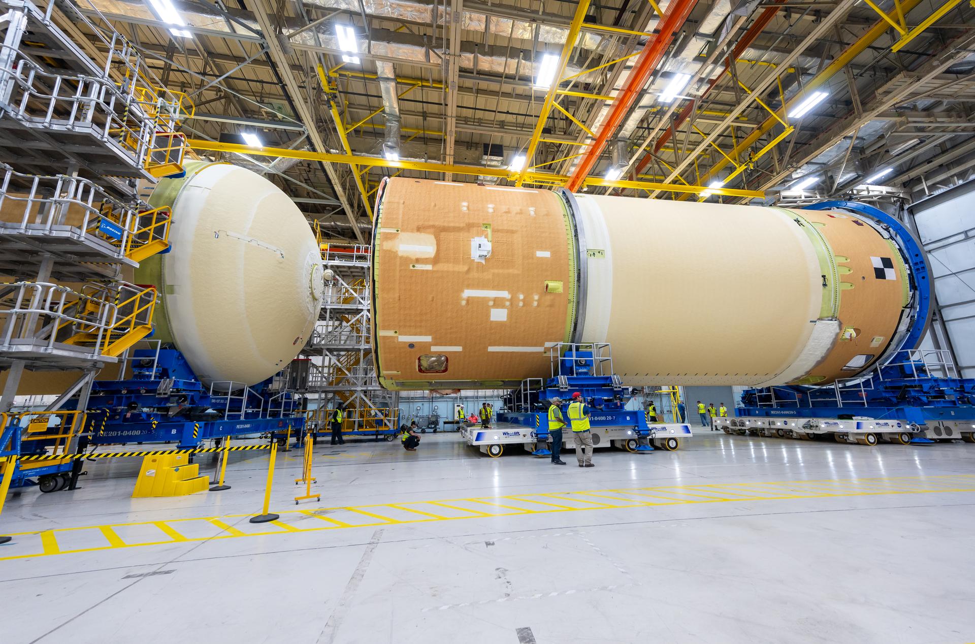
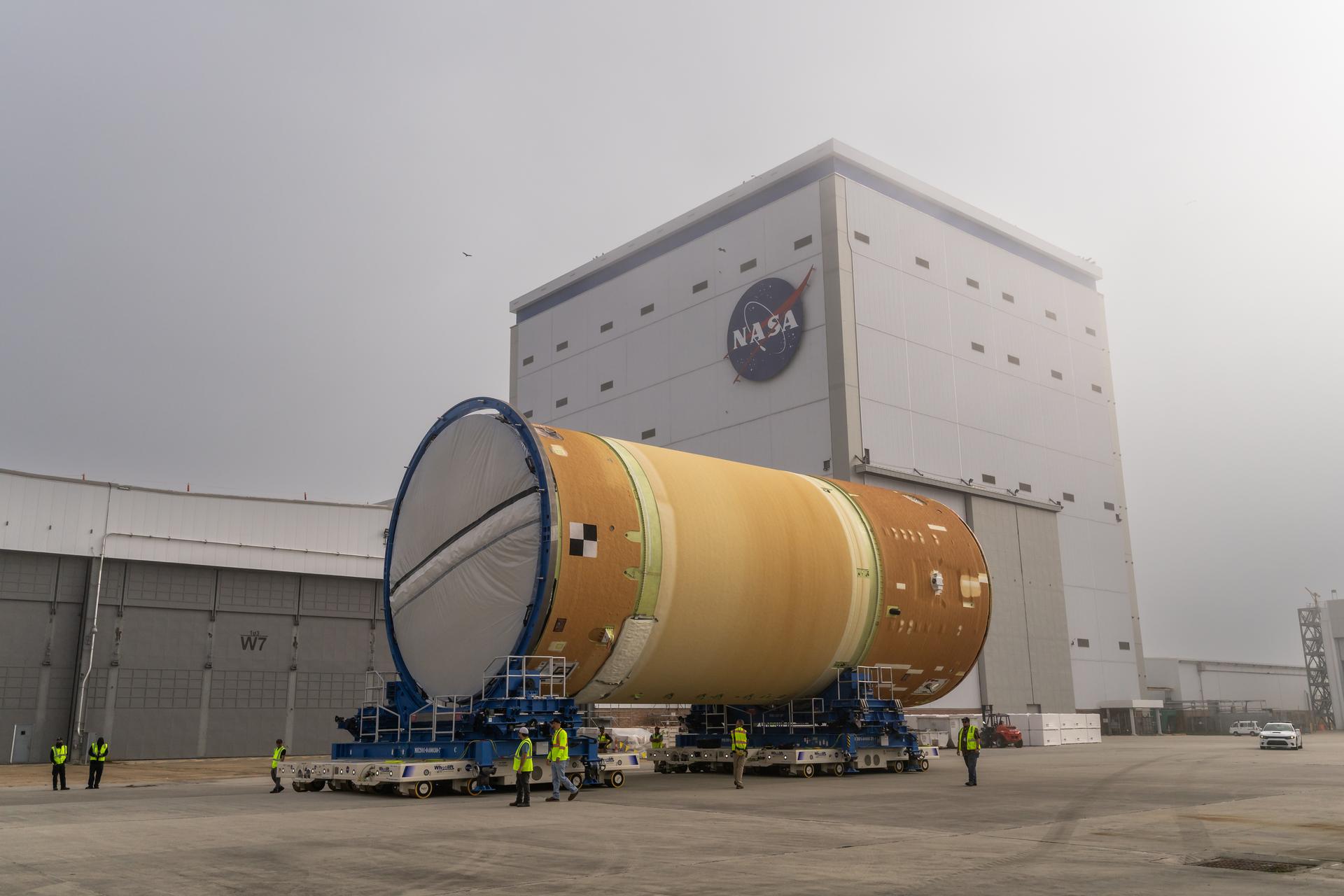
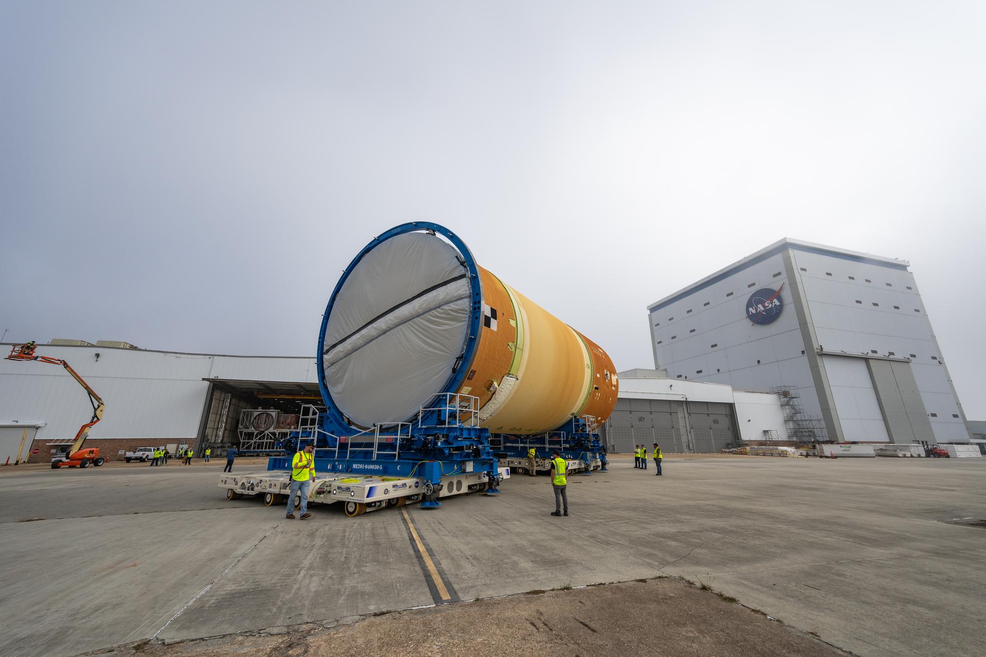
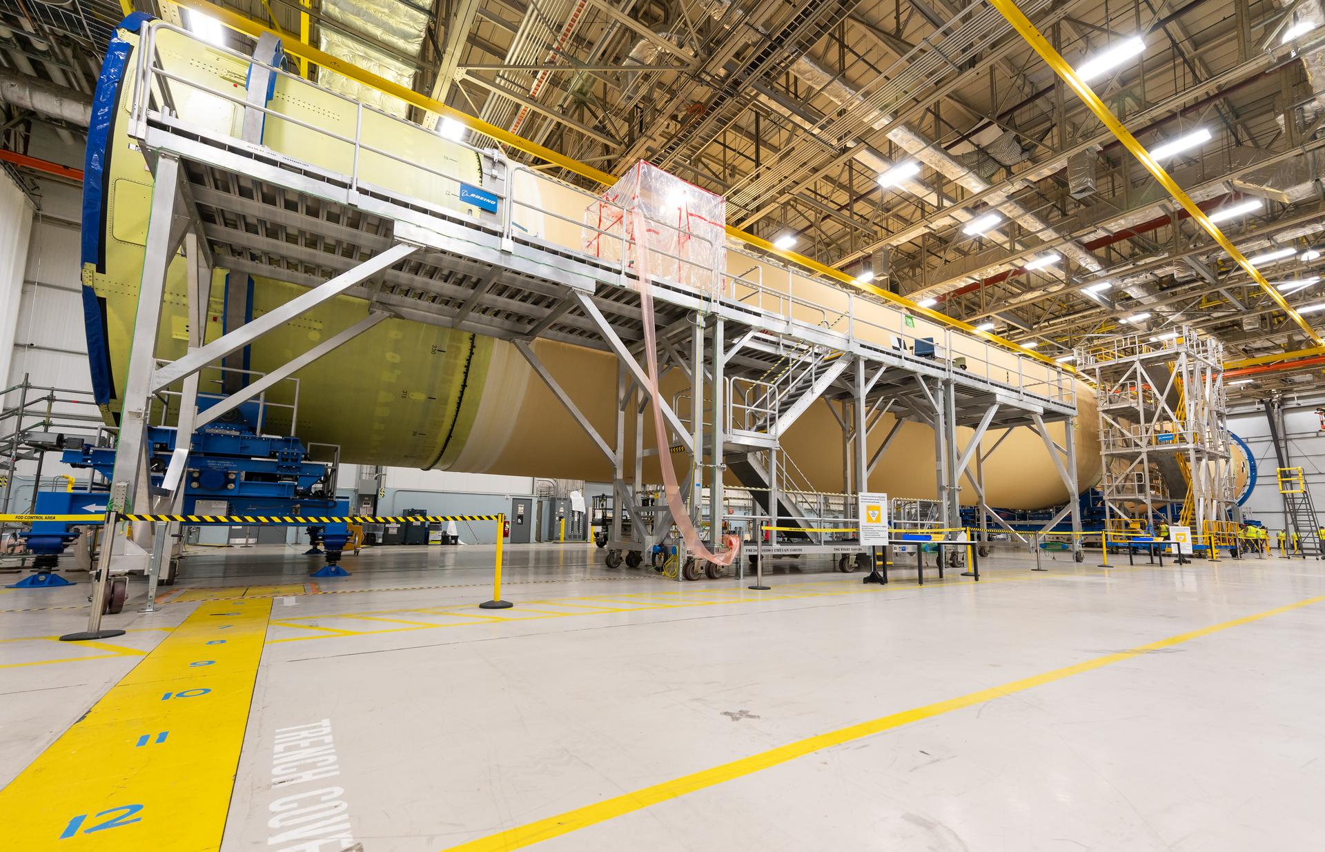
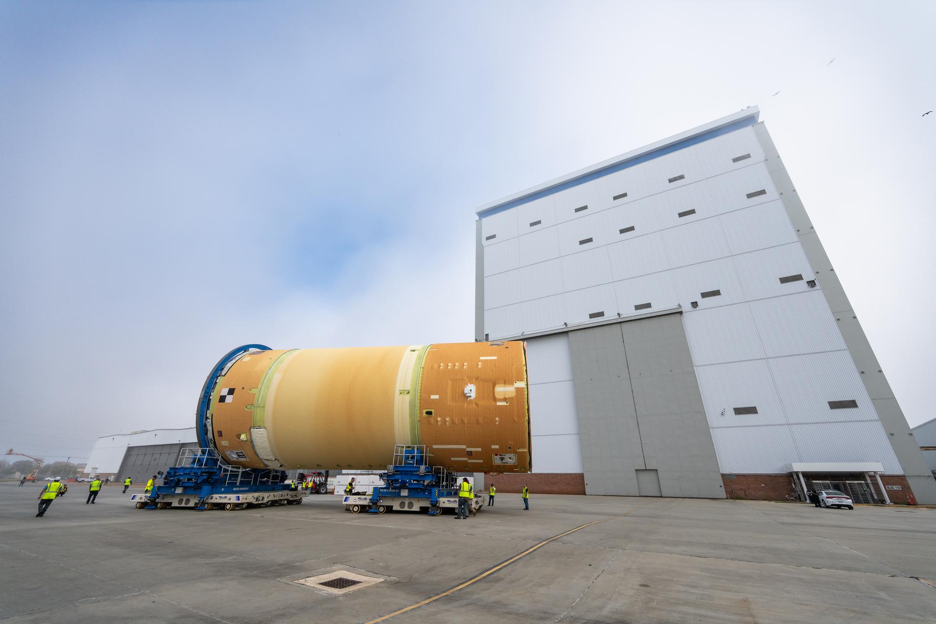
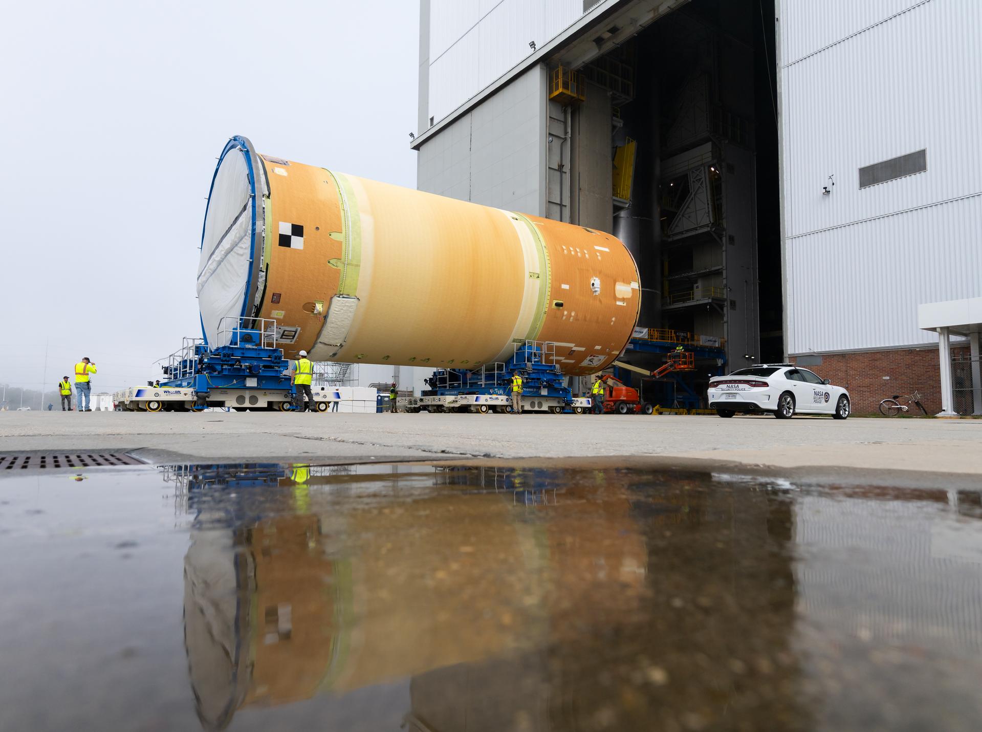
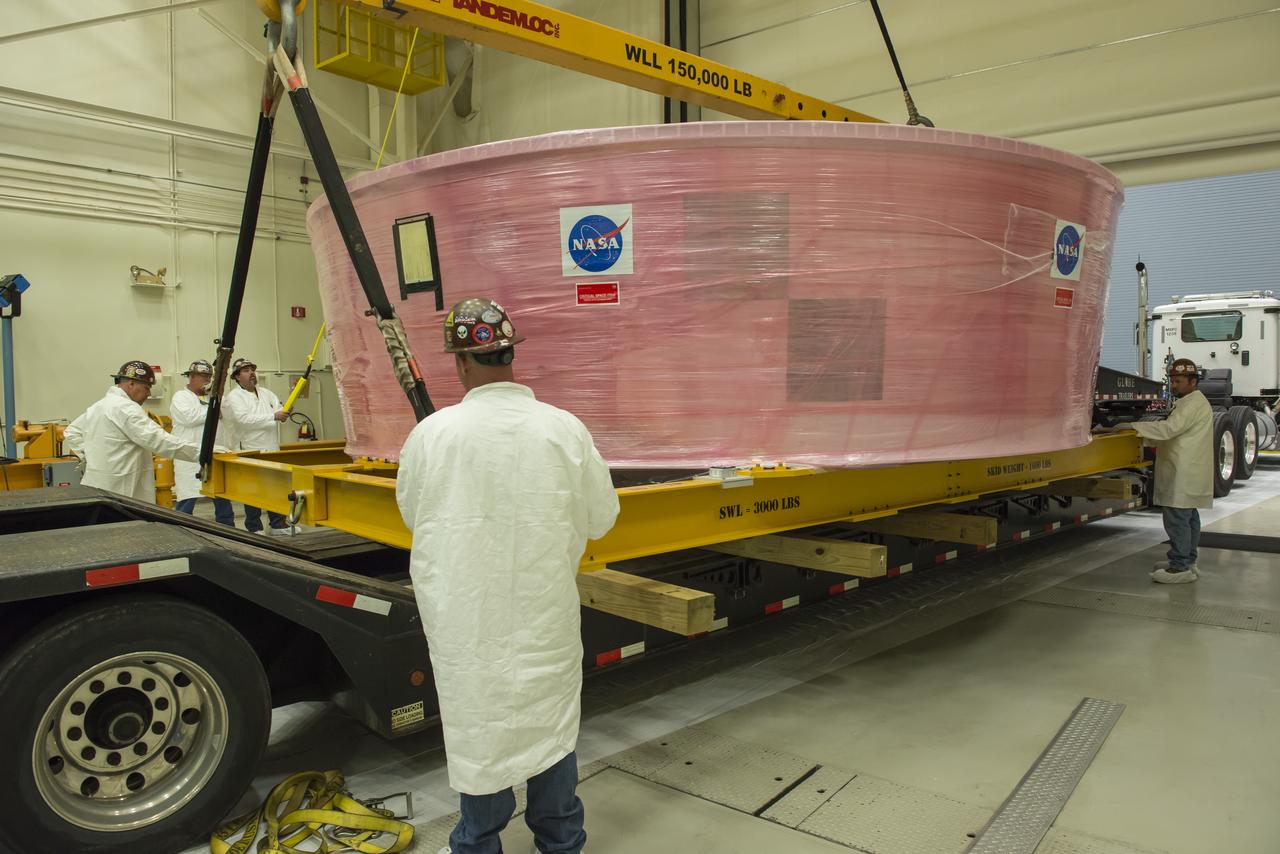
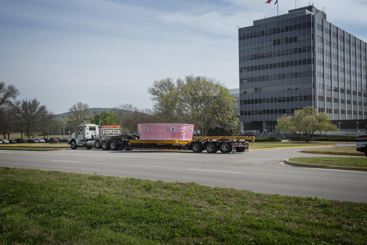
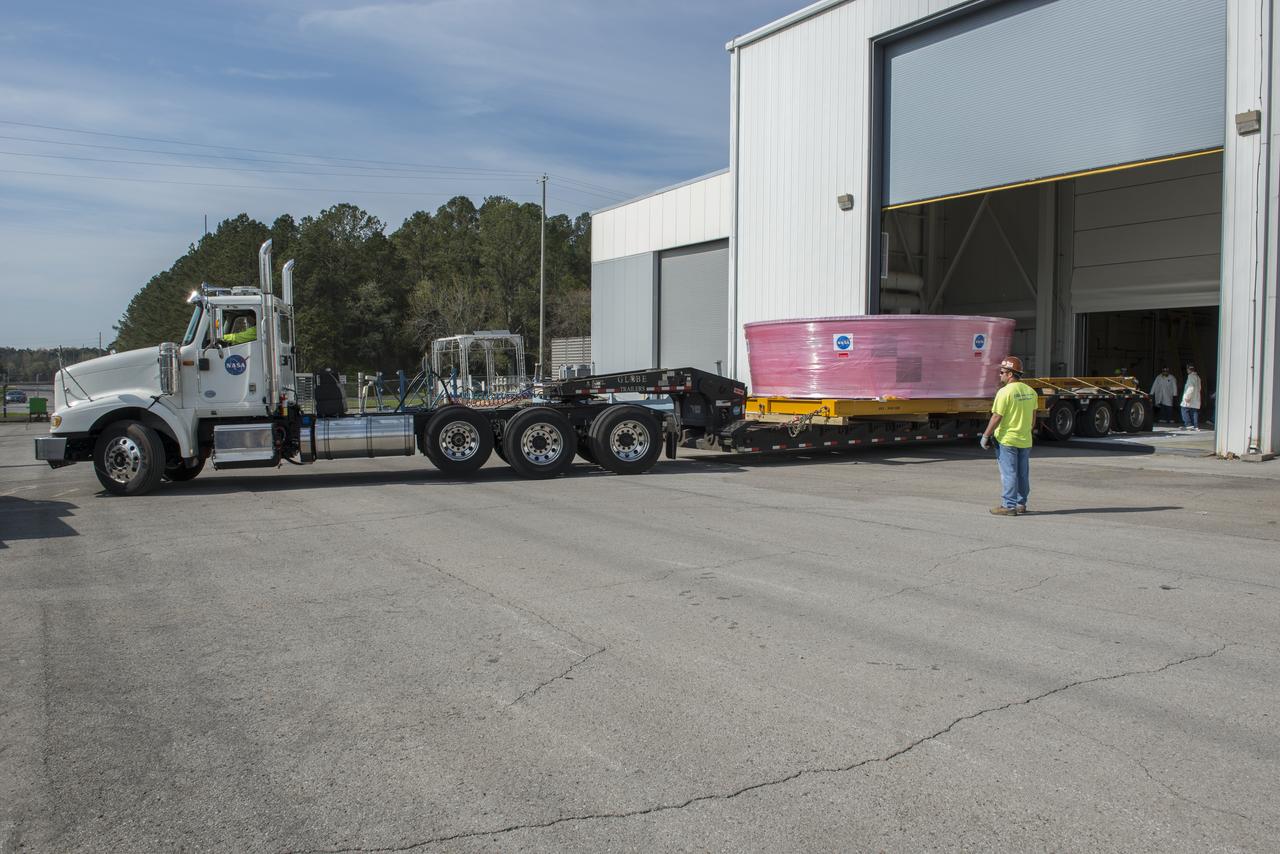
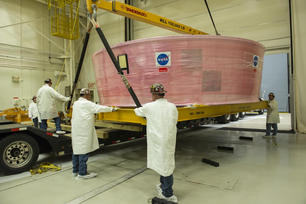
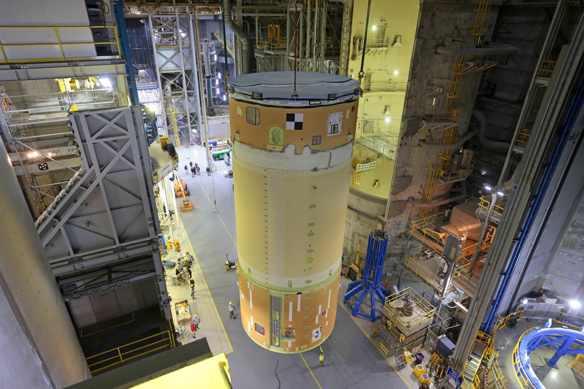
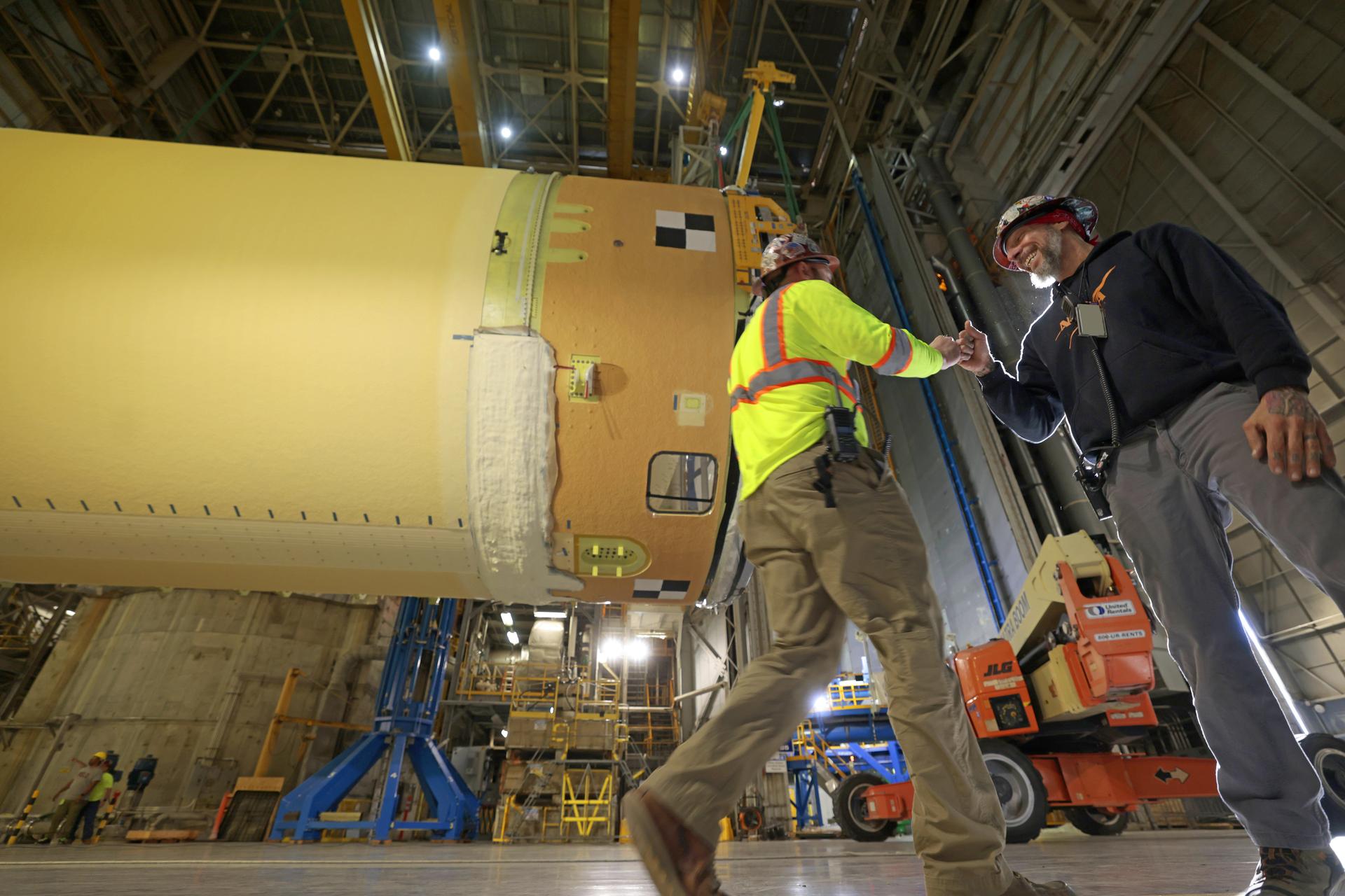
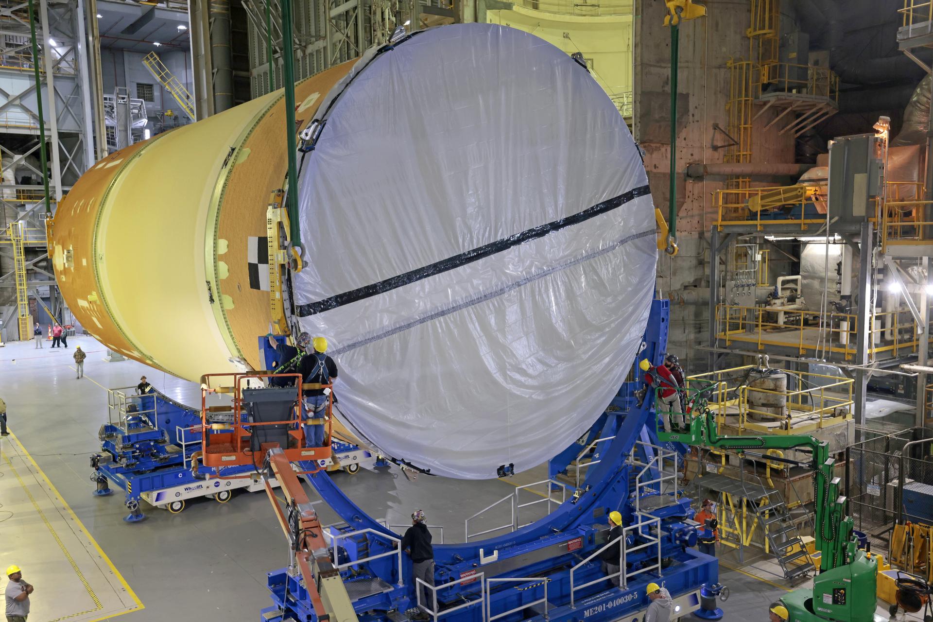
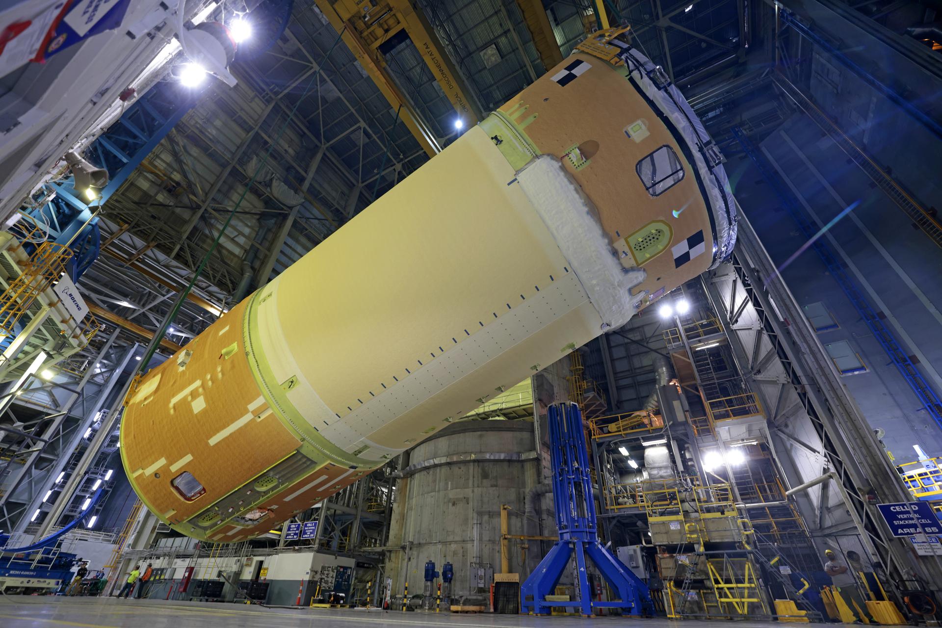
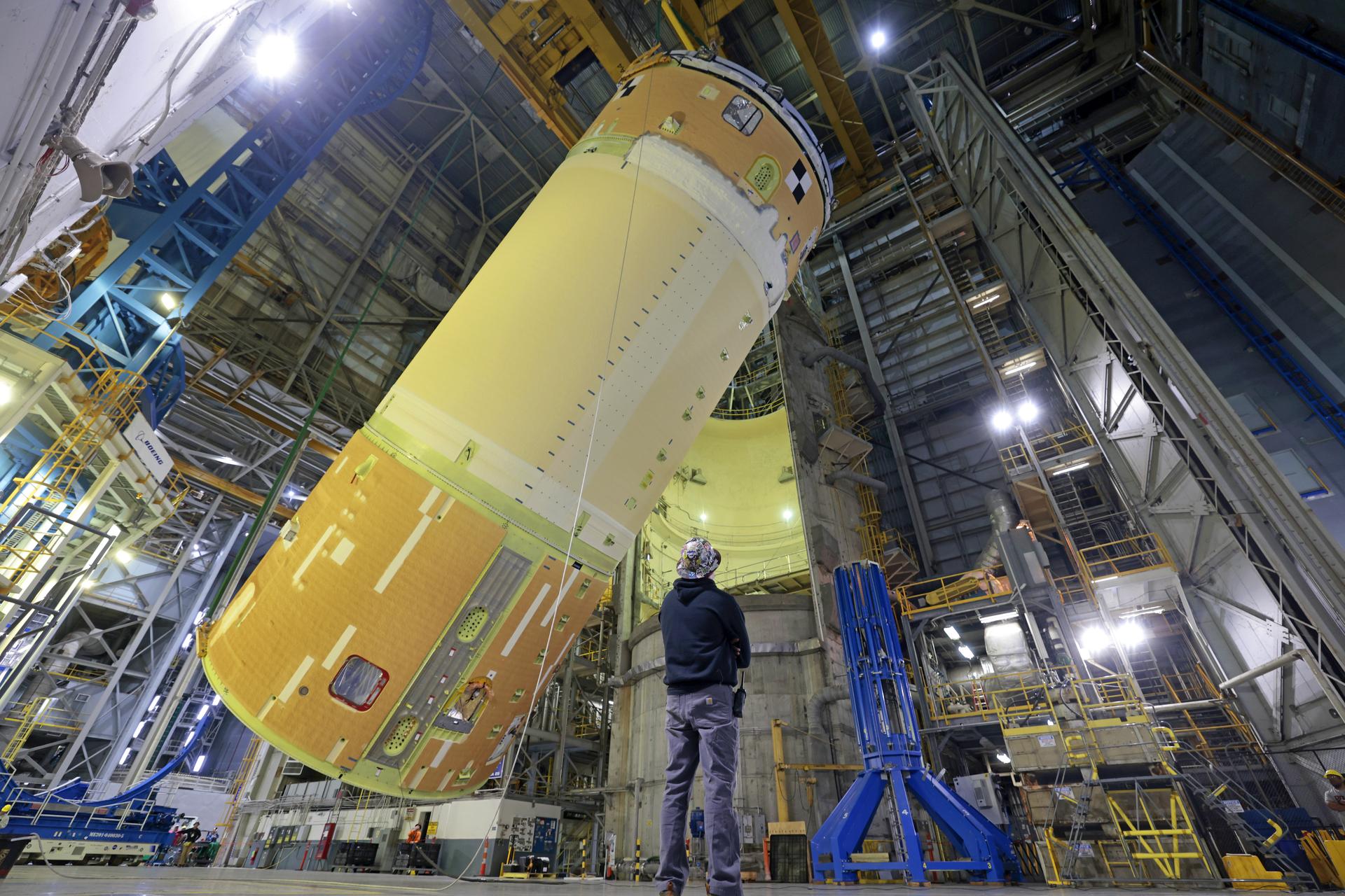
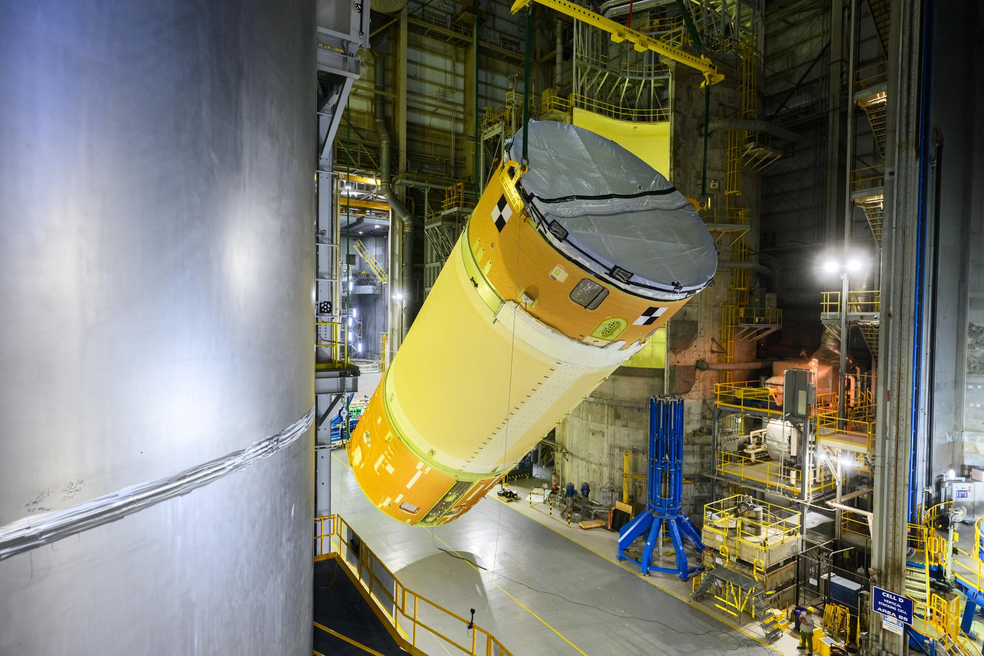
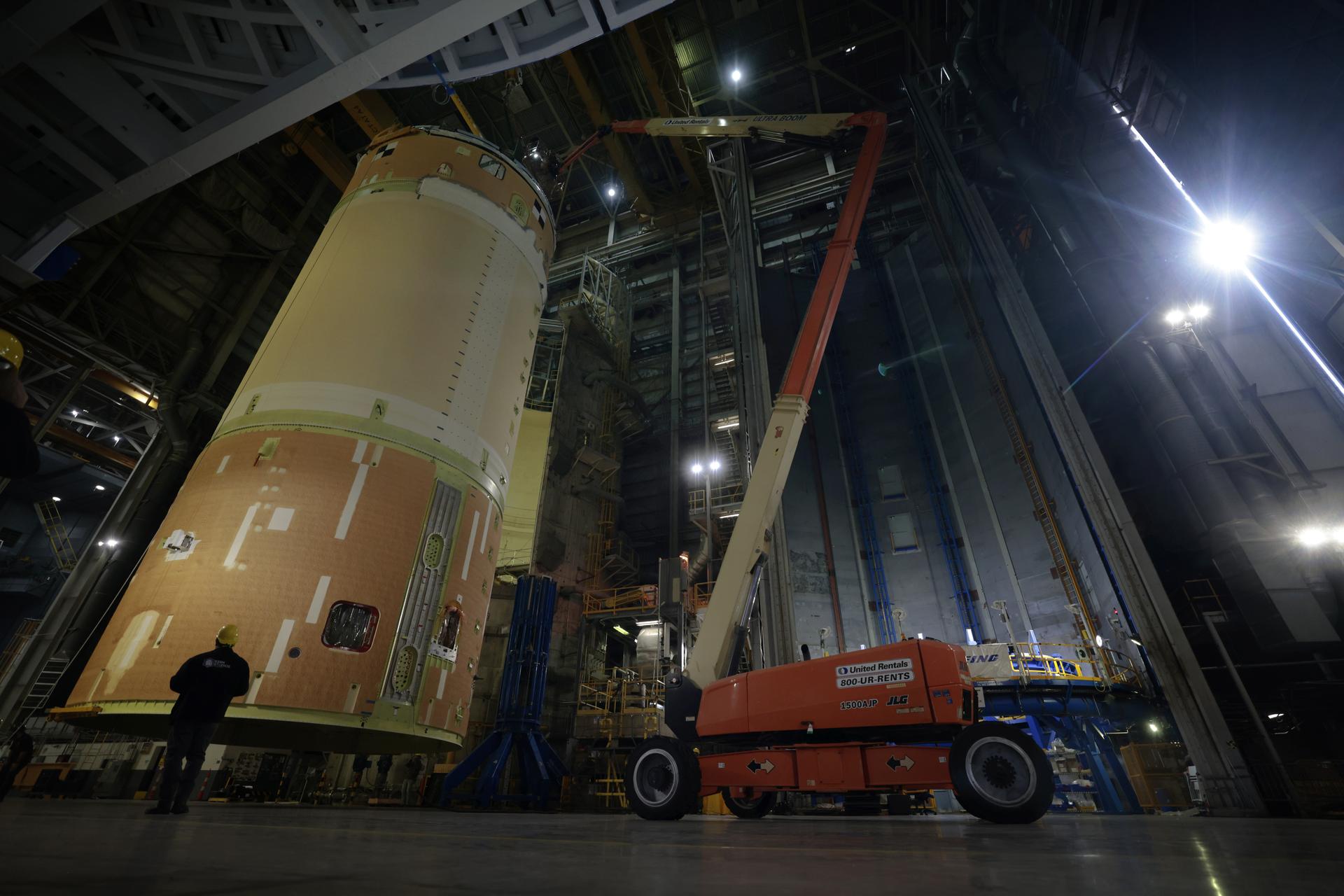
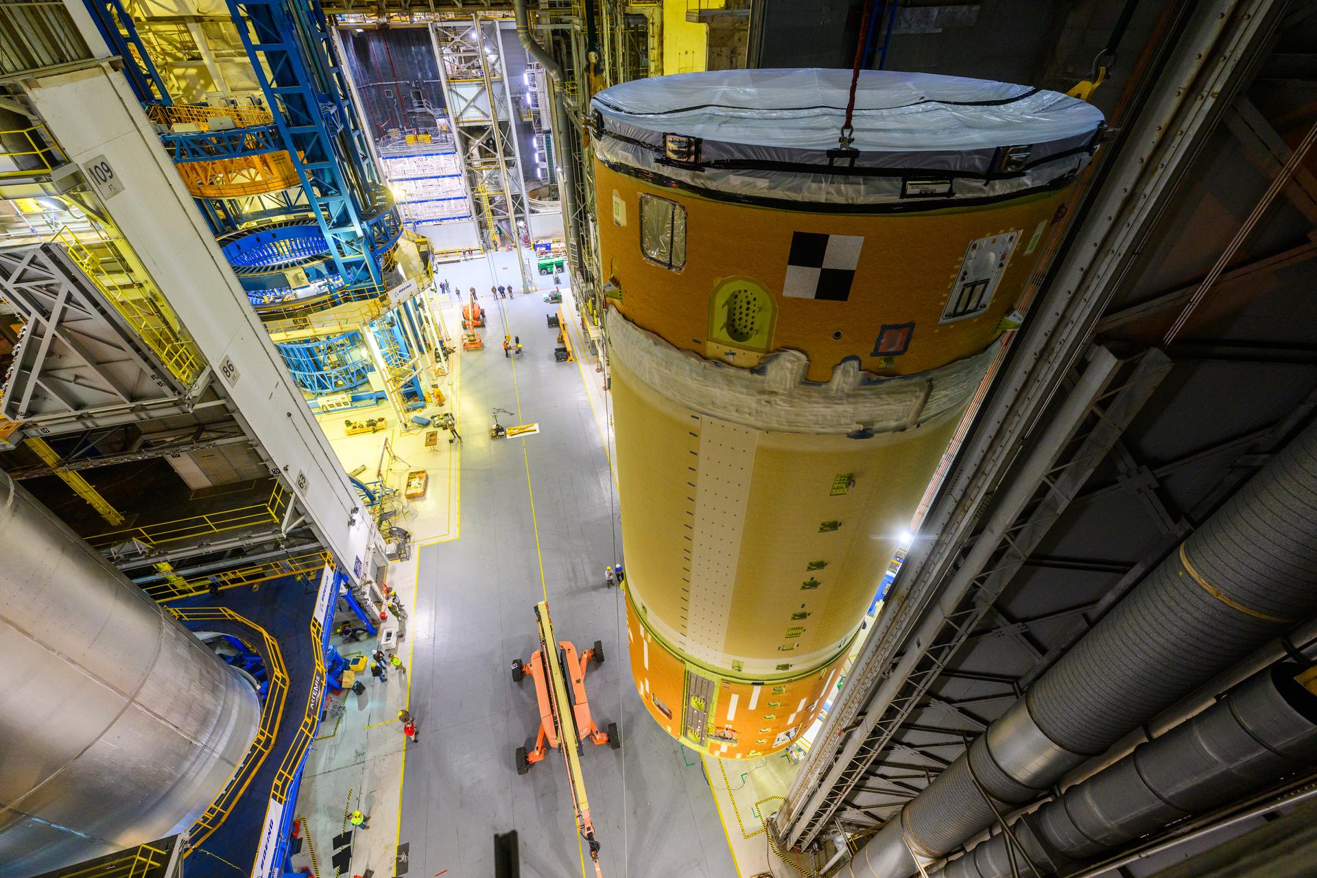
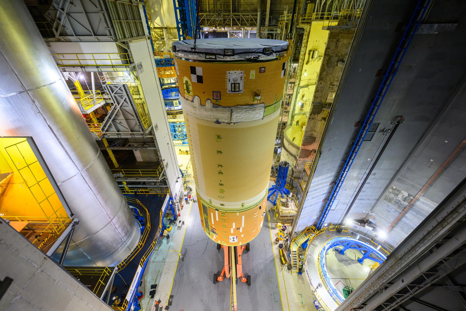
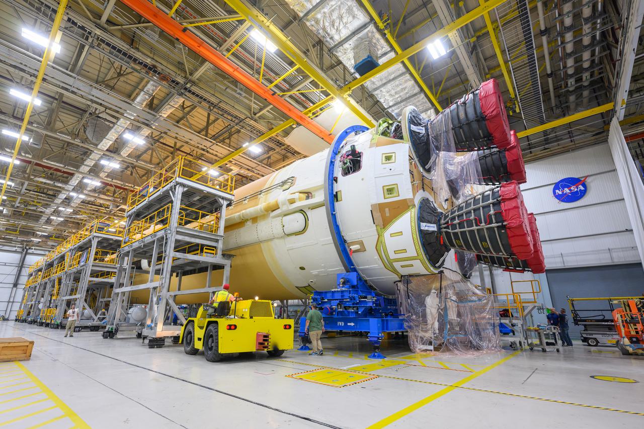
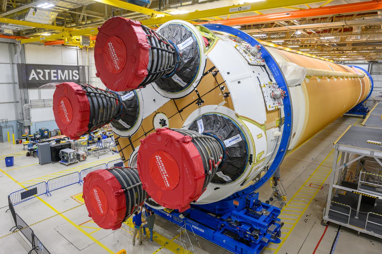
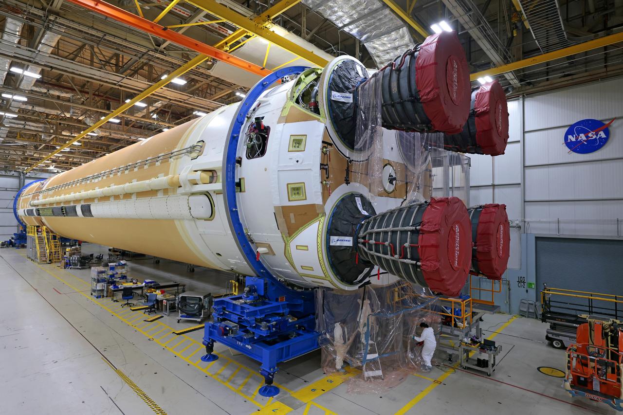
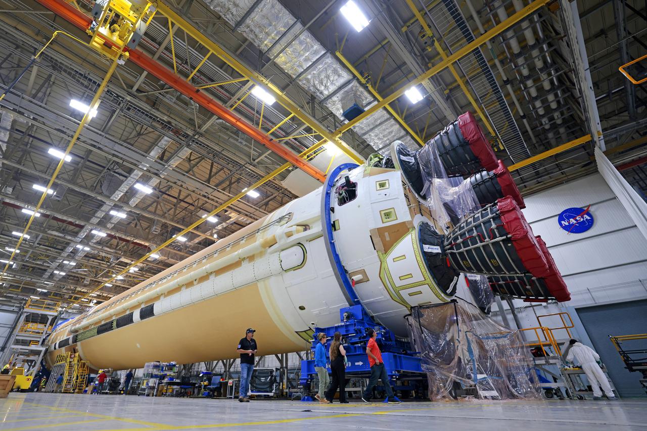
Artemis III major Join 3 moves to final integration Move crews at NASA’s Michoud Assembly Facility in New Orleans, lift the forward-joined flight hardware for the agency’s SLS (Space Launch System) rocket out of a stacking cell in the vertical assembly building on Dec. 19, 2025. The forward join, which consists of the intertank, liquid oxygen tank, and forward skirt, will be used on the core stage slated for NASA’s Artemis III mission. Teams moved the flight hardware from the cell and set it atop self-propelled mobile transporters. The article was brought to the factory’s final assembly area on Dec. 27, 2025 where it will be mated to the core stage’s previously joined liquid hydrogen tank and undergo further integration. The core stage, along with its four RS-25 engines, produce more than two million pounds of thrust to help launch NASA’s Orion spacecraft, astronauts, and supplies beyond Earth’s orbit and to the lunar surface for Artemis.