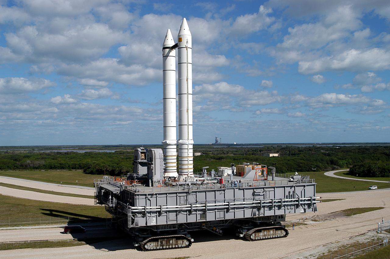
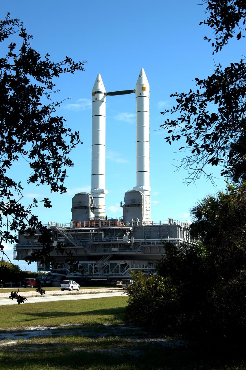
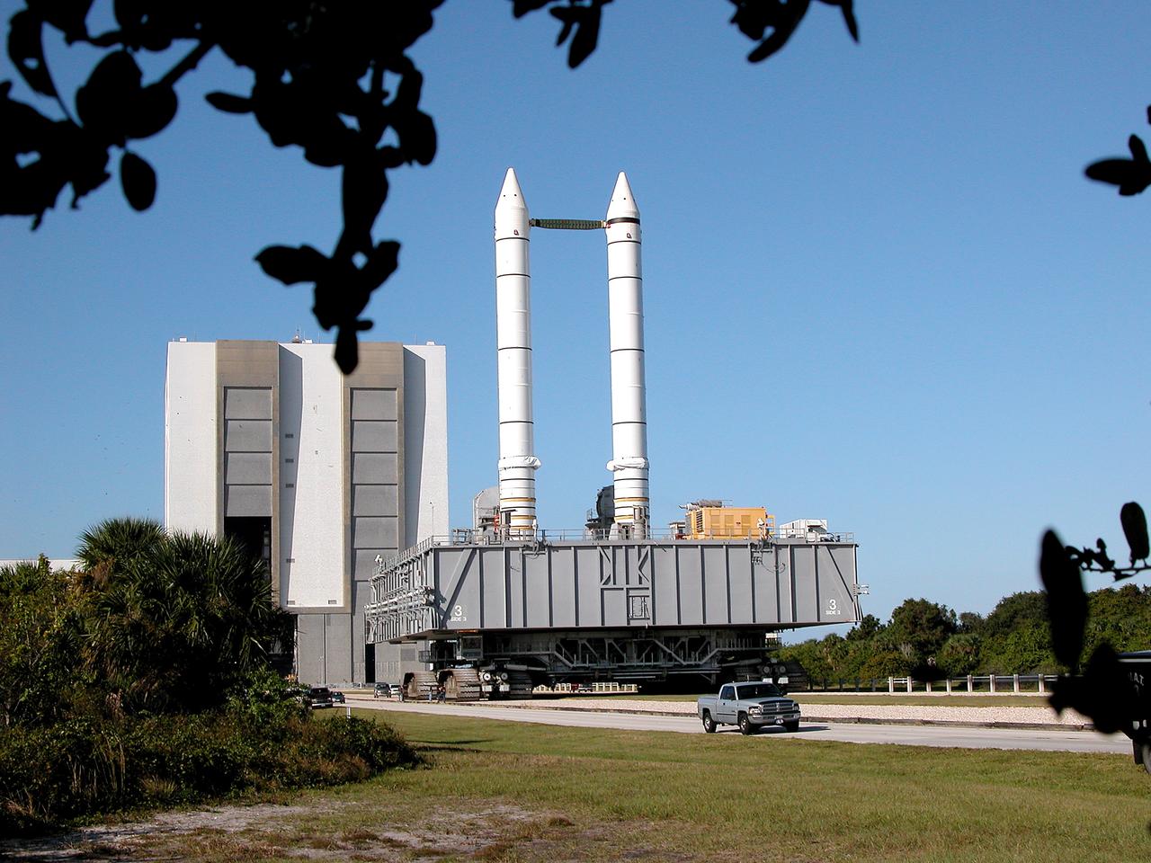
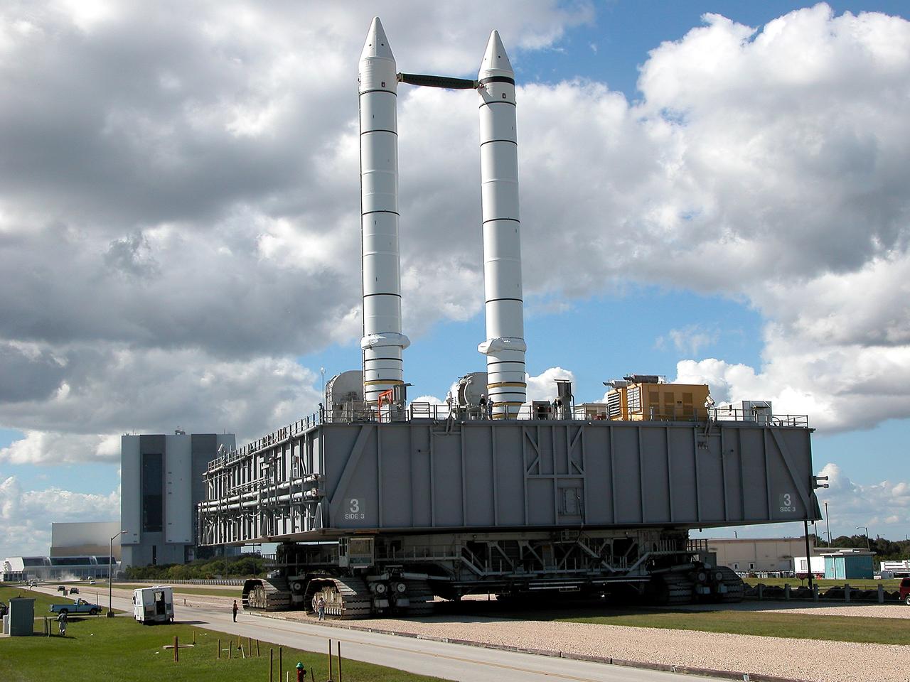
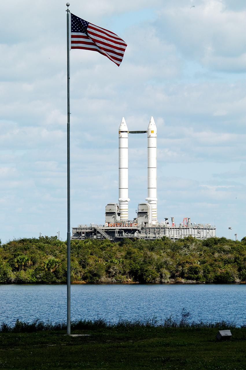
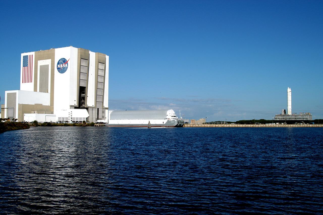
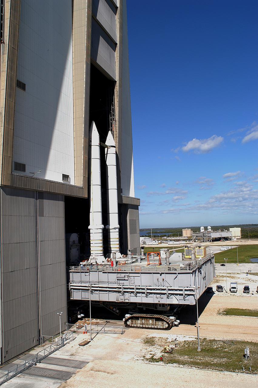
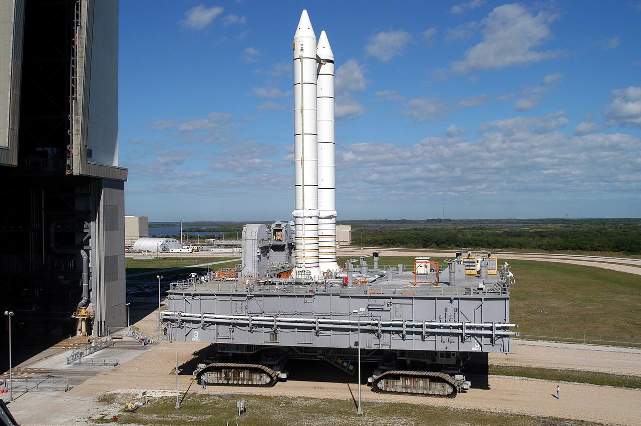
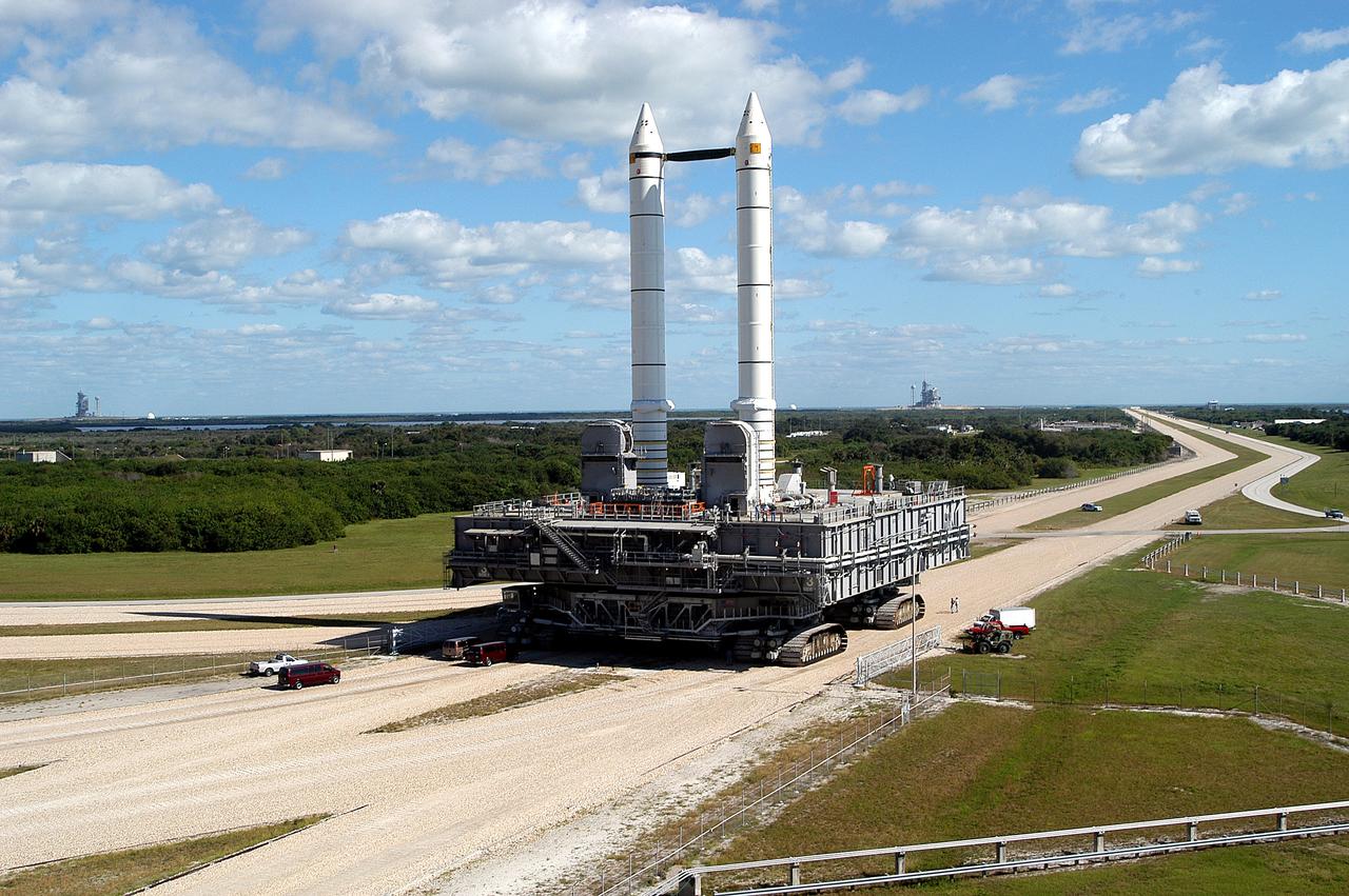
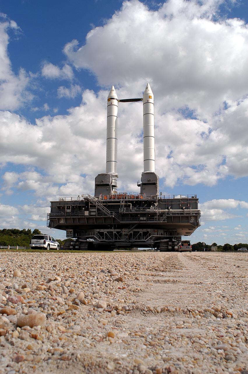
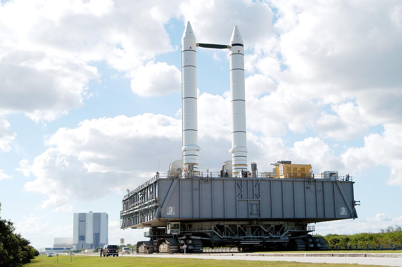
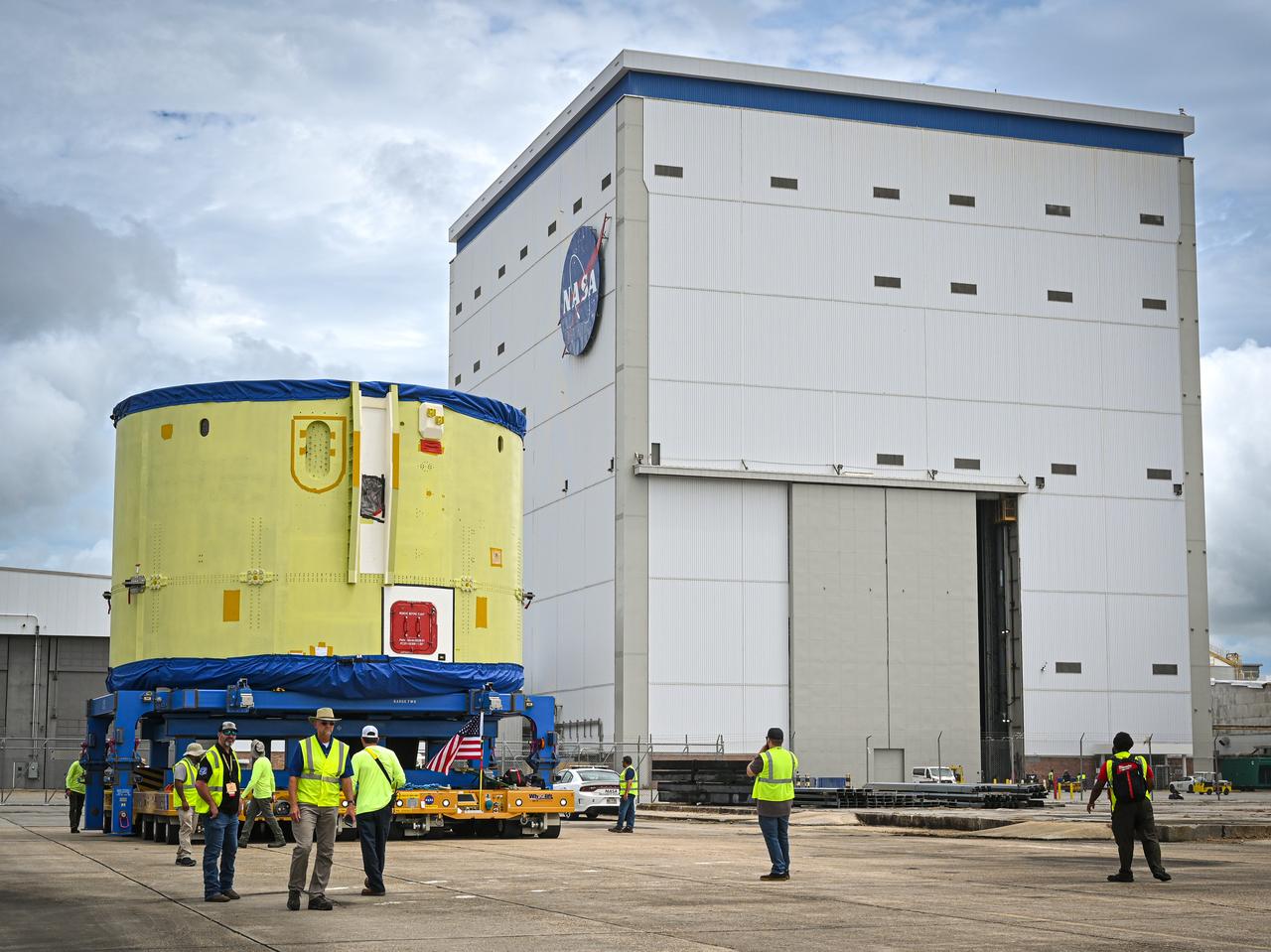
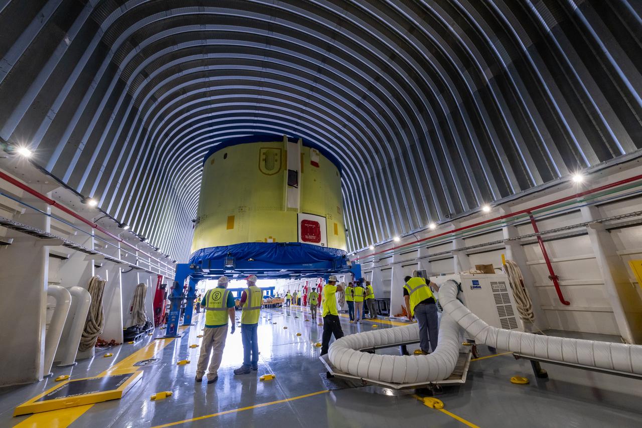
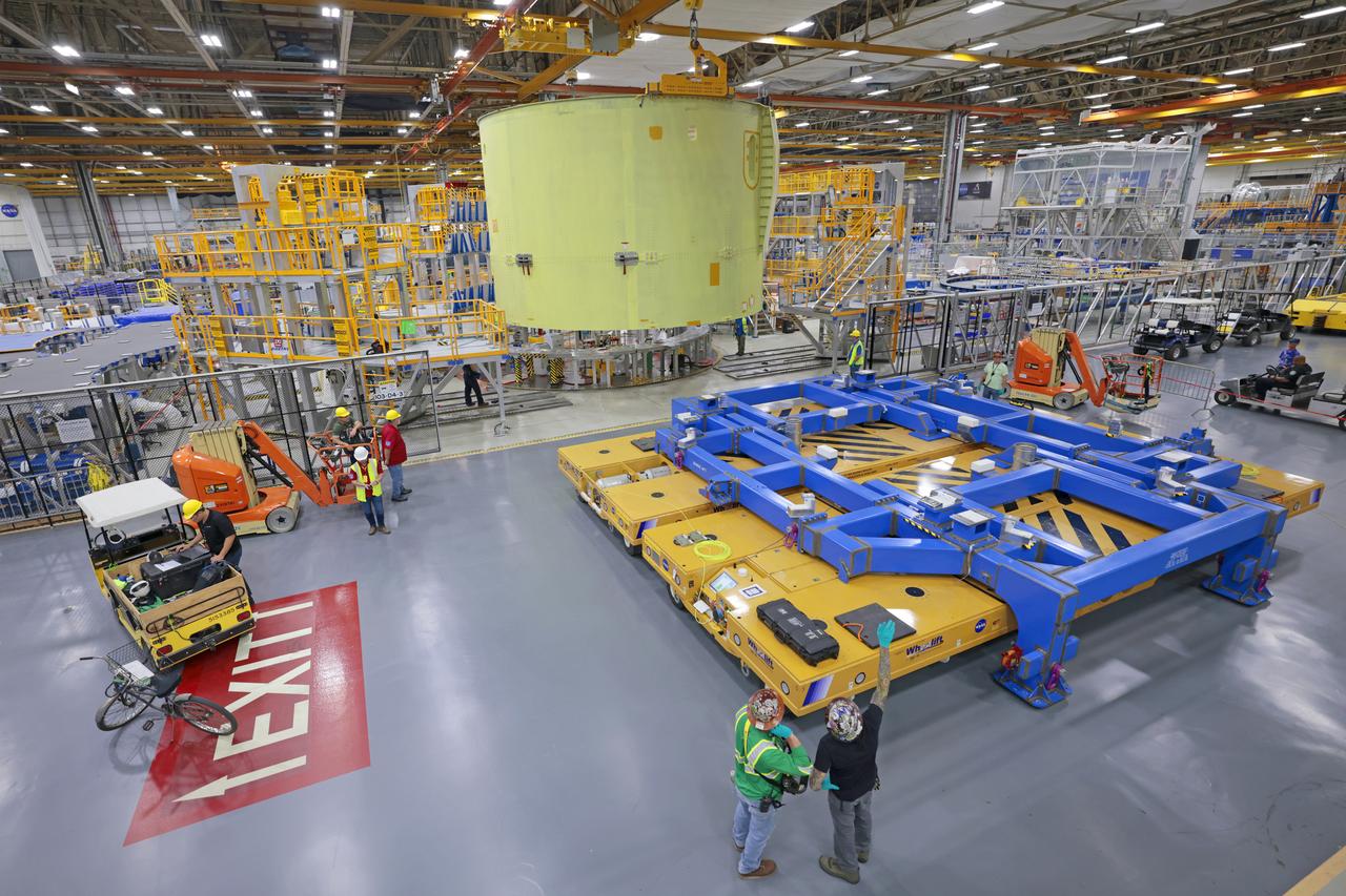
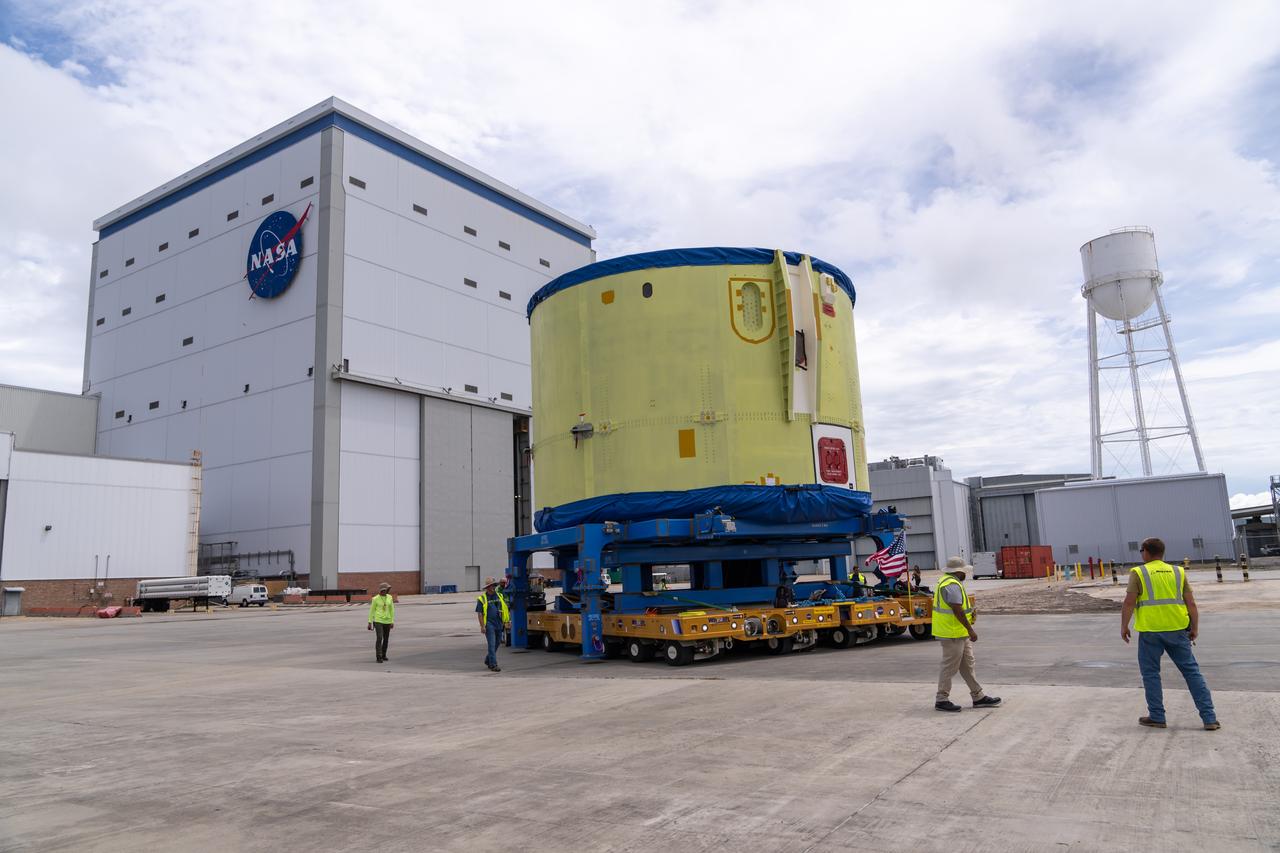
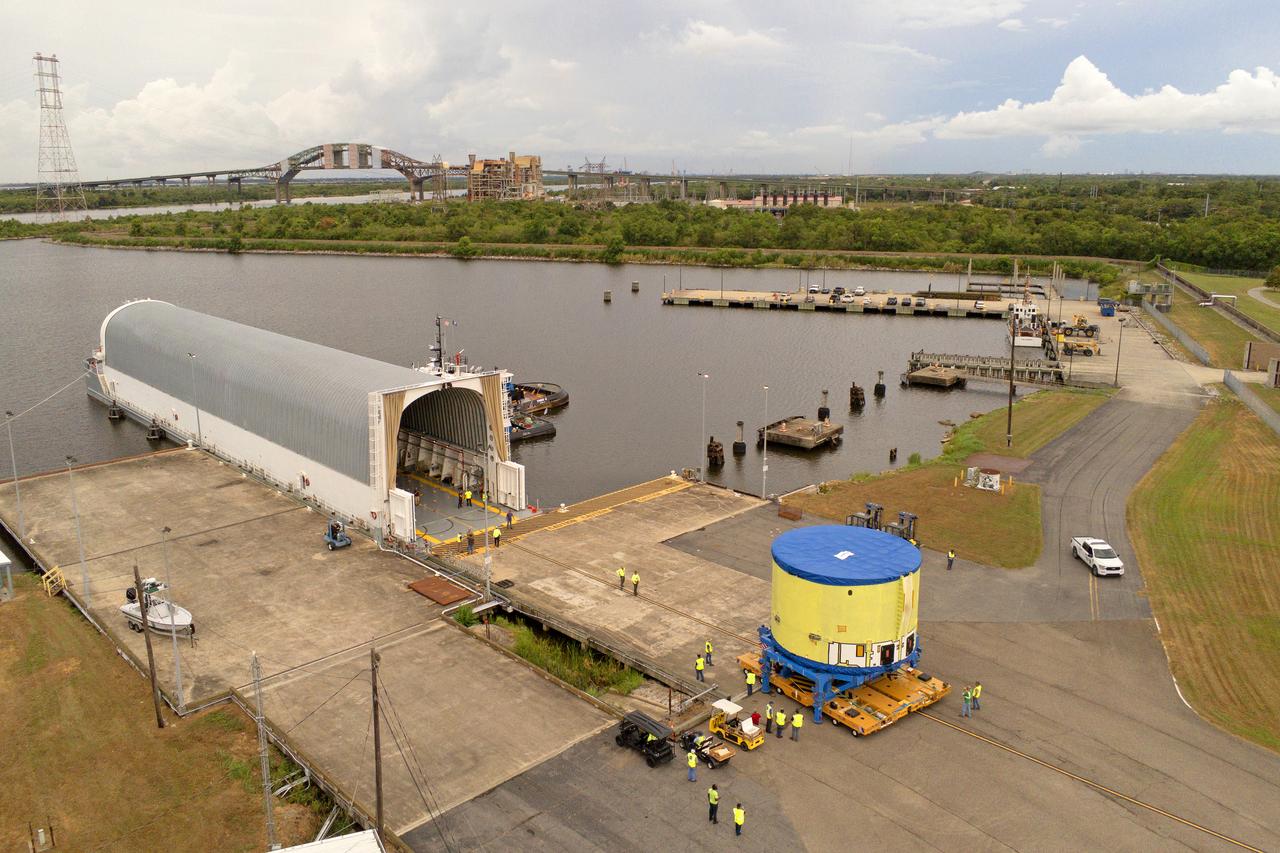
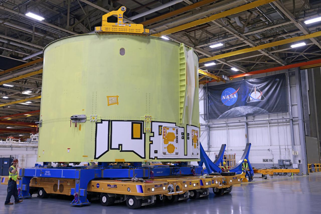
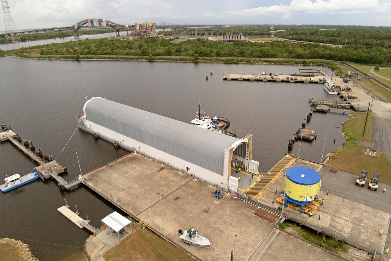
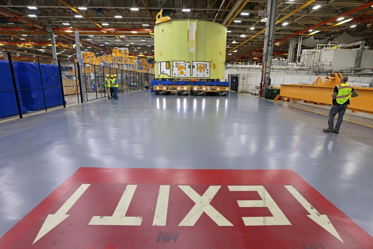
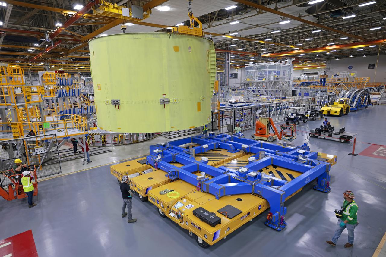
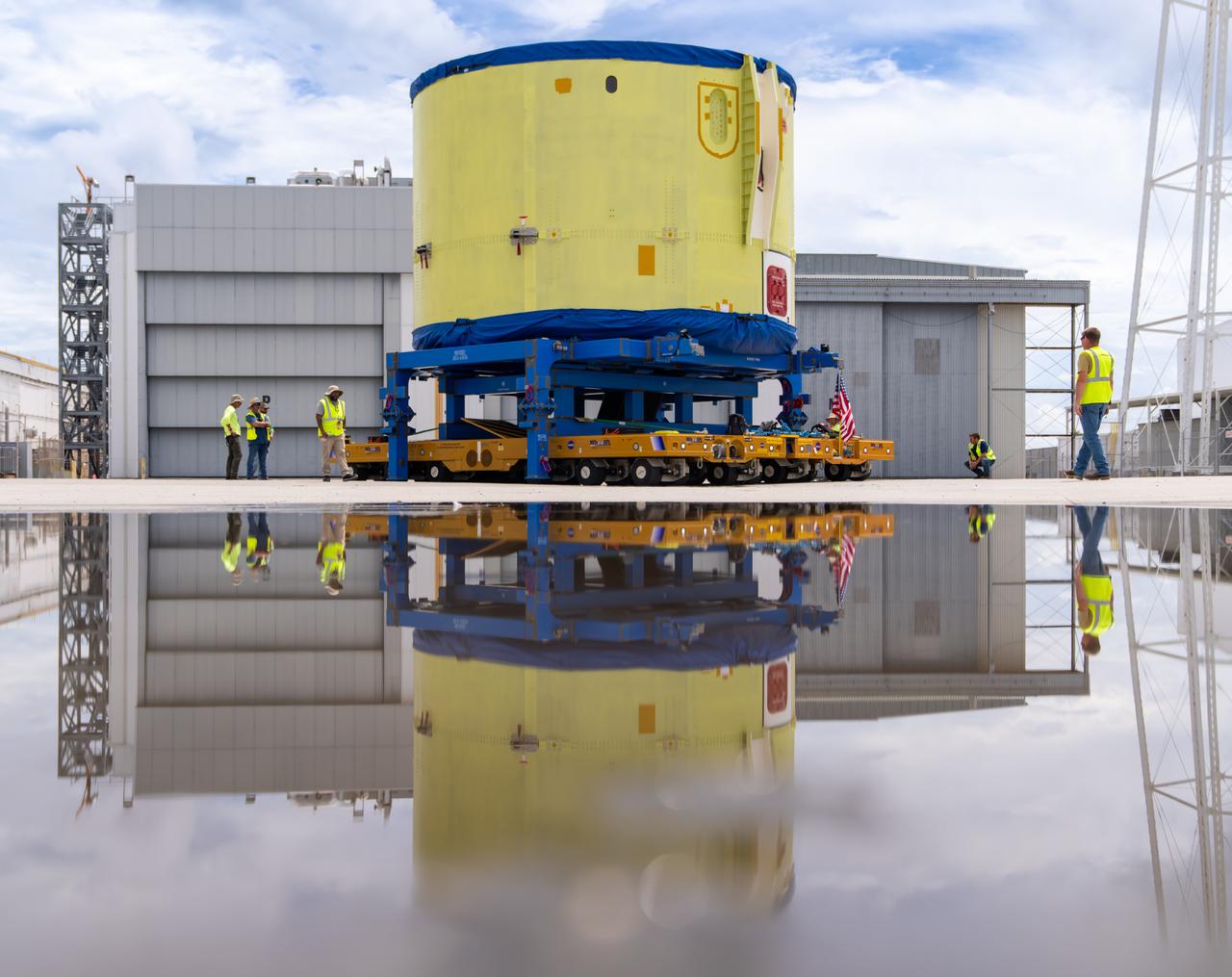
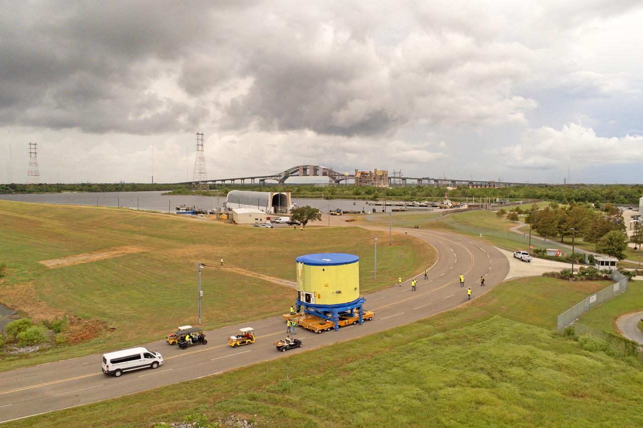
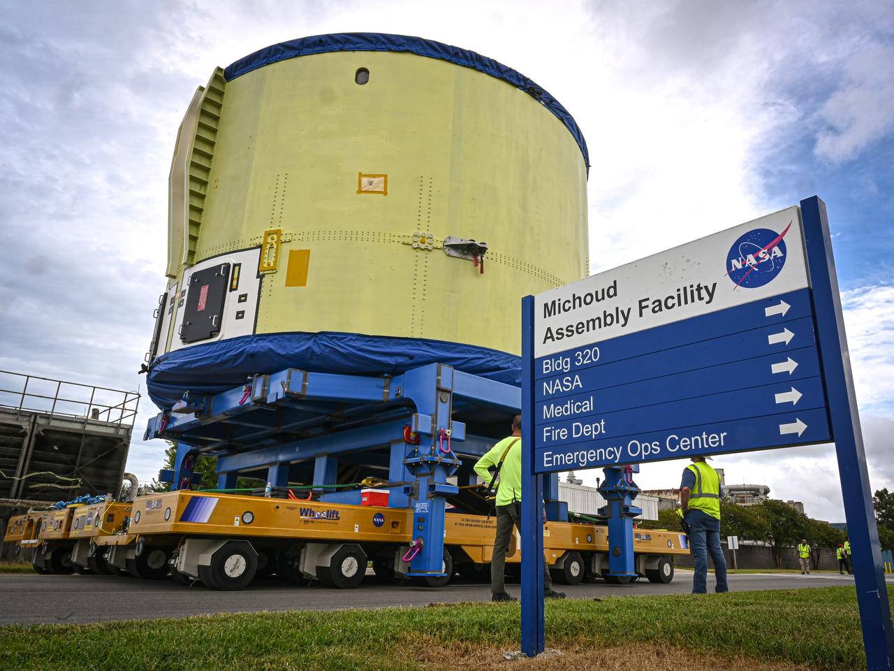
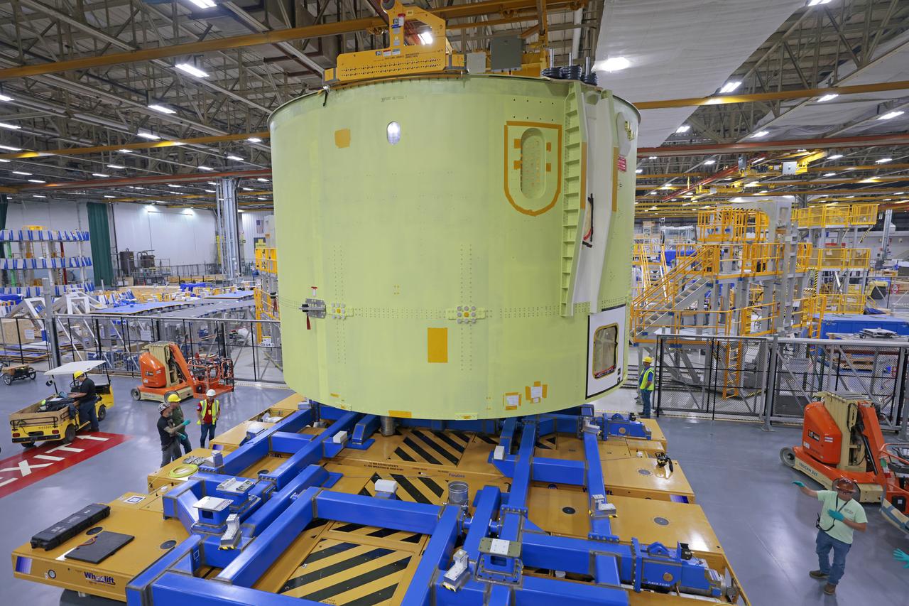
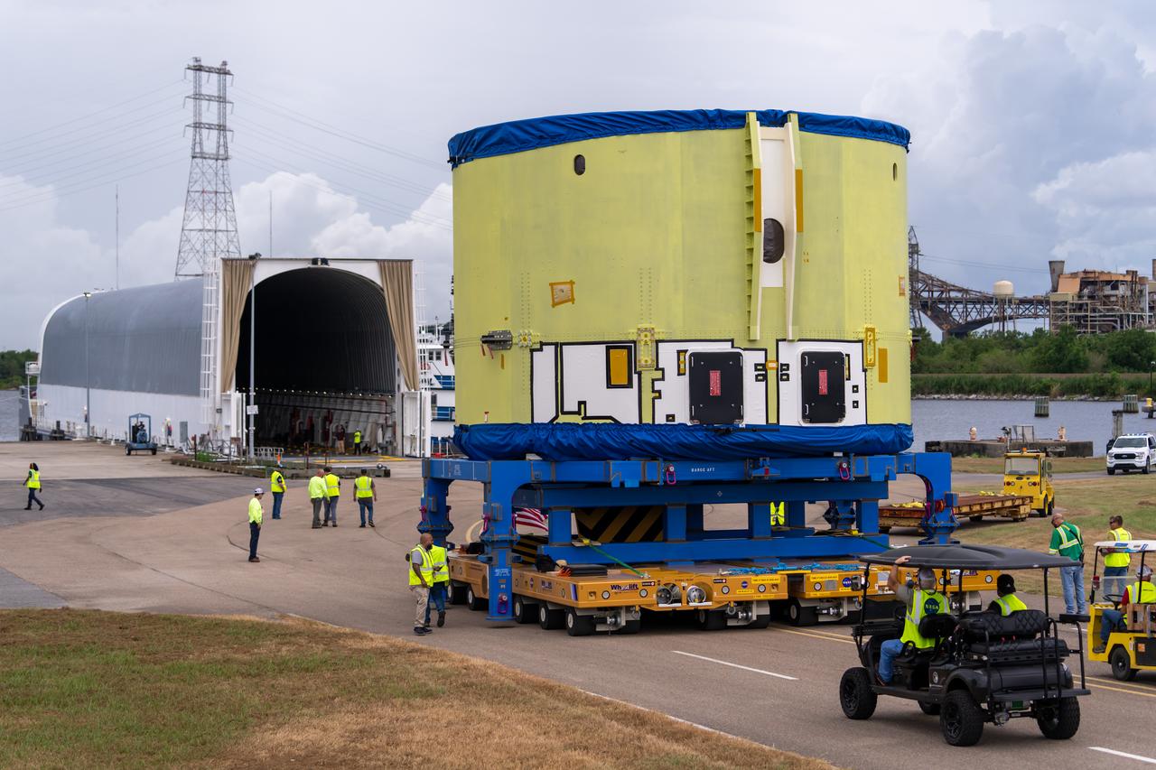
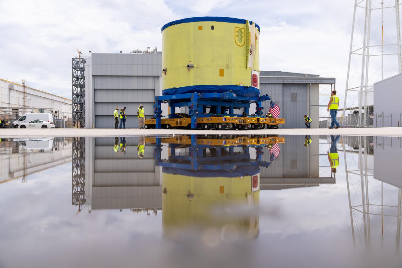
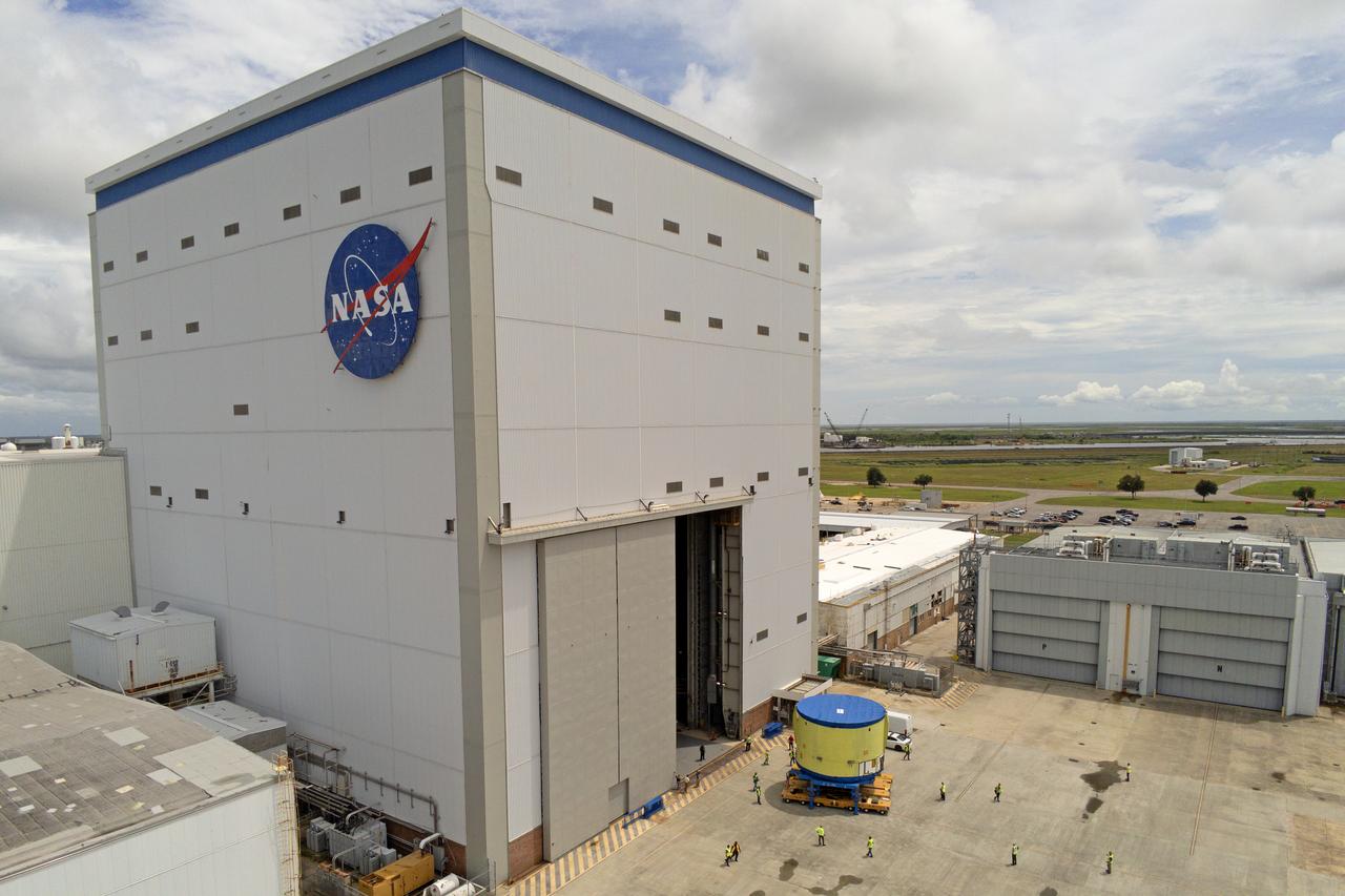
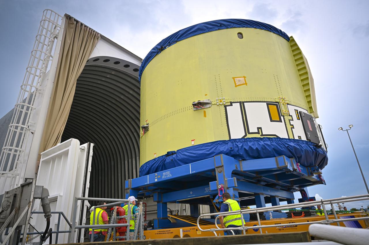
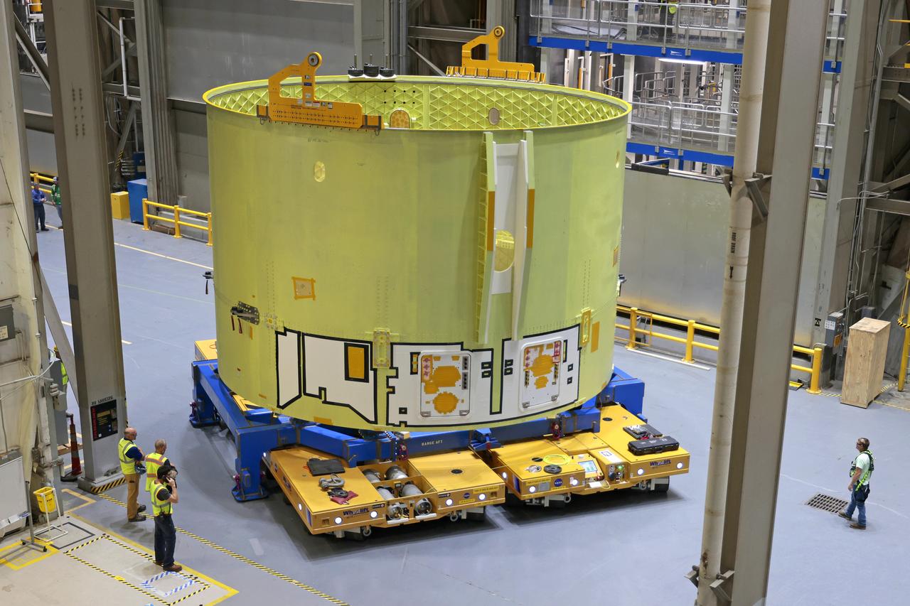
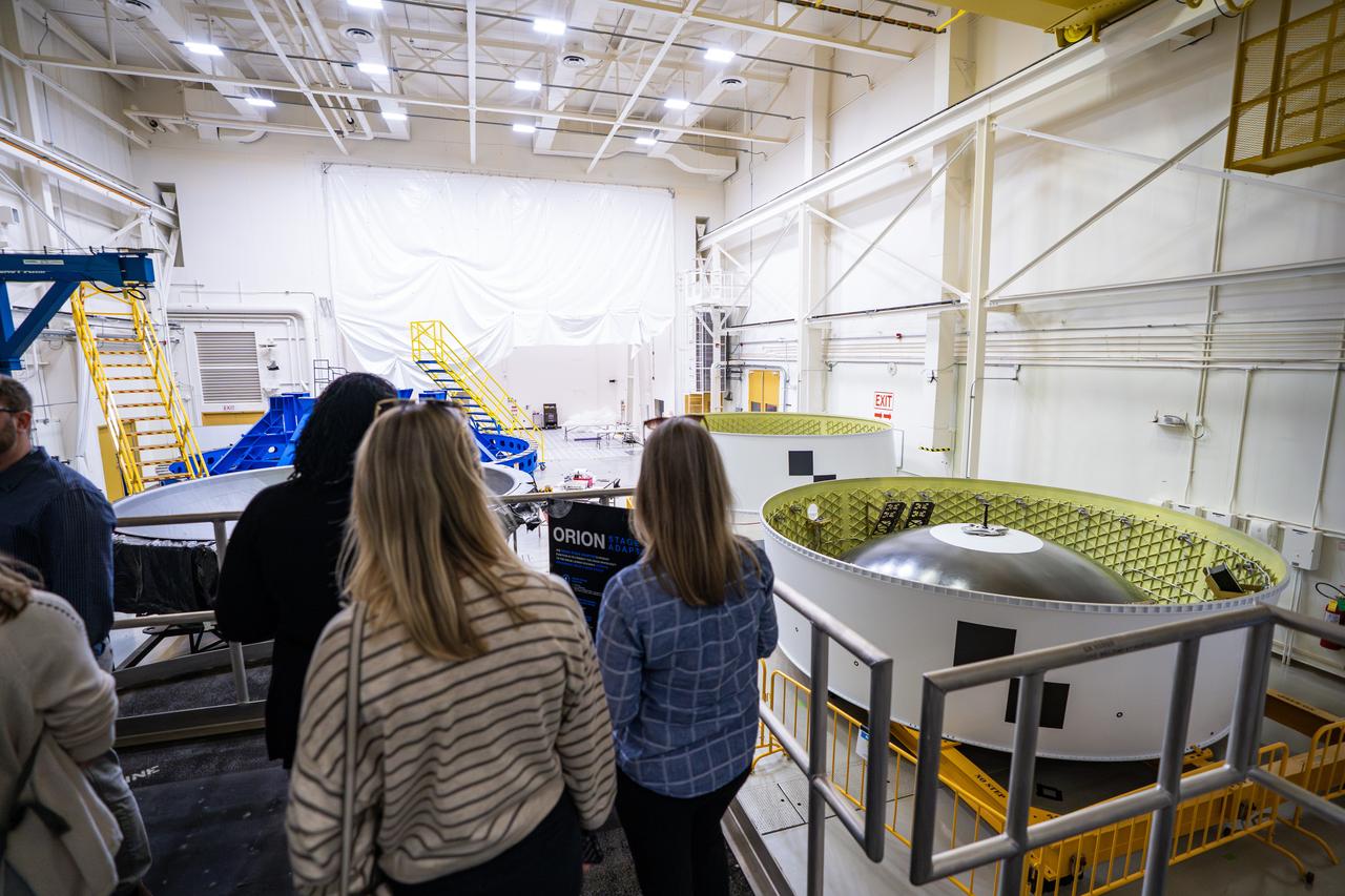
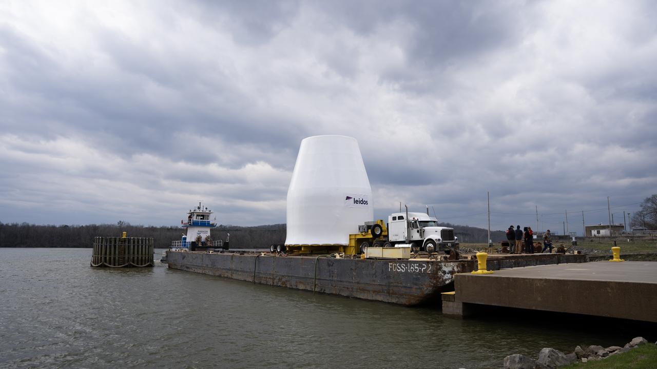
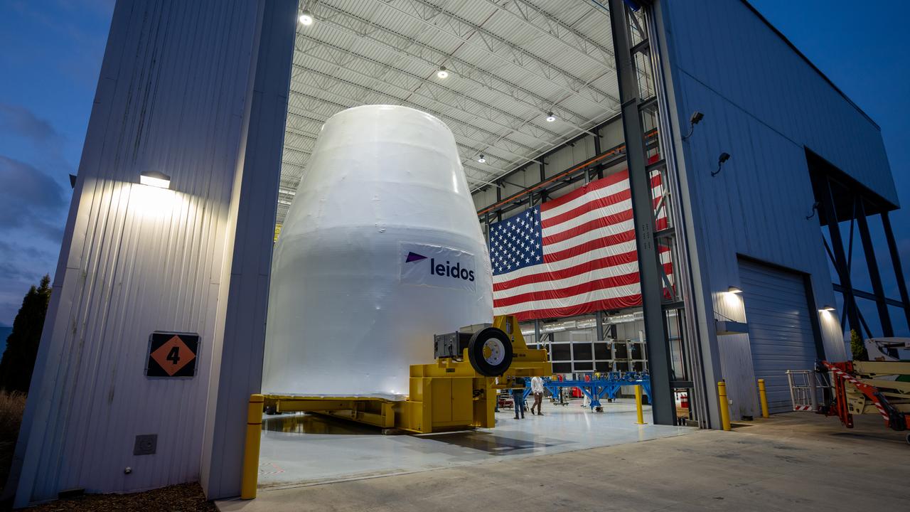
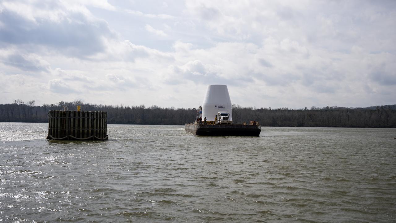
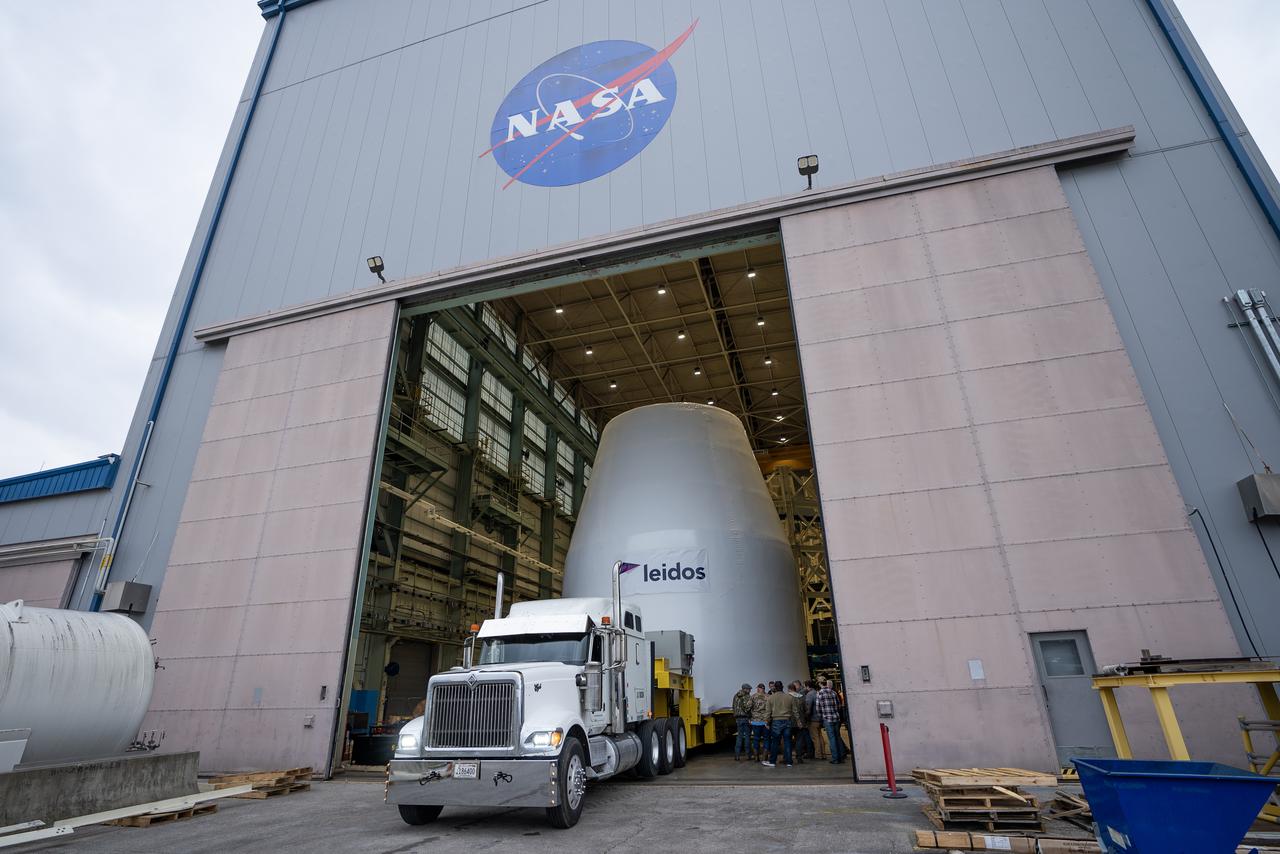
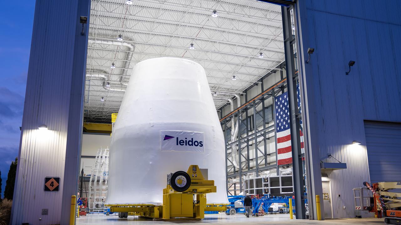
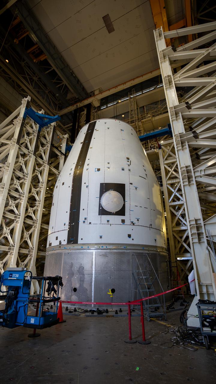
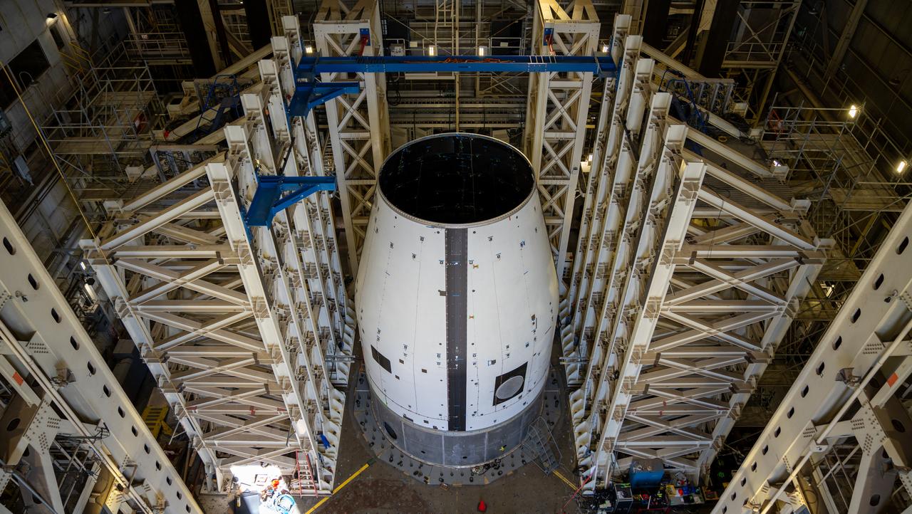
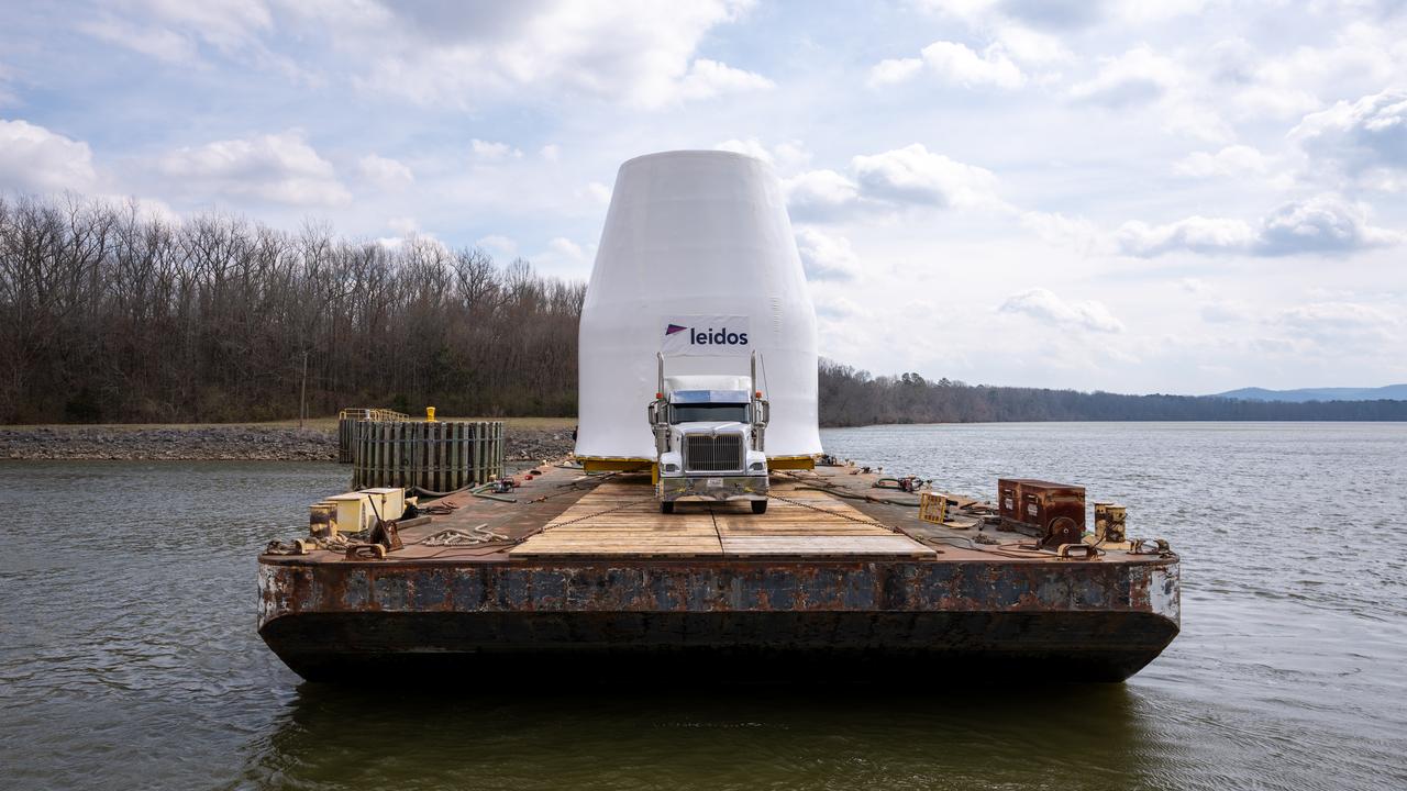
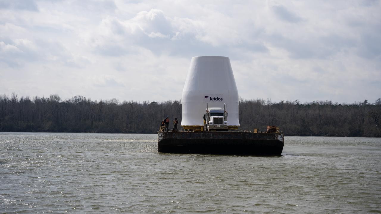
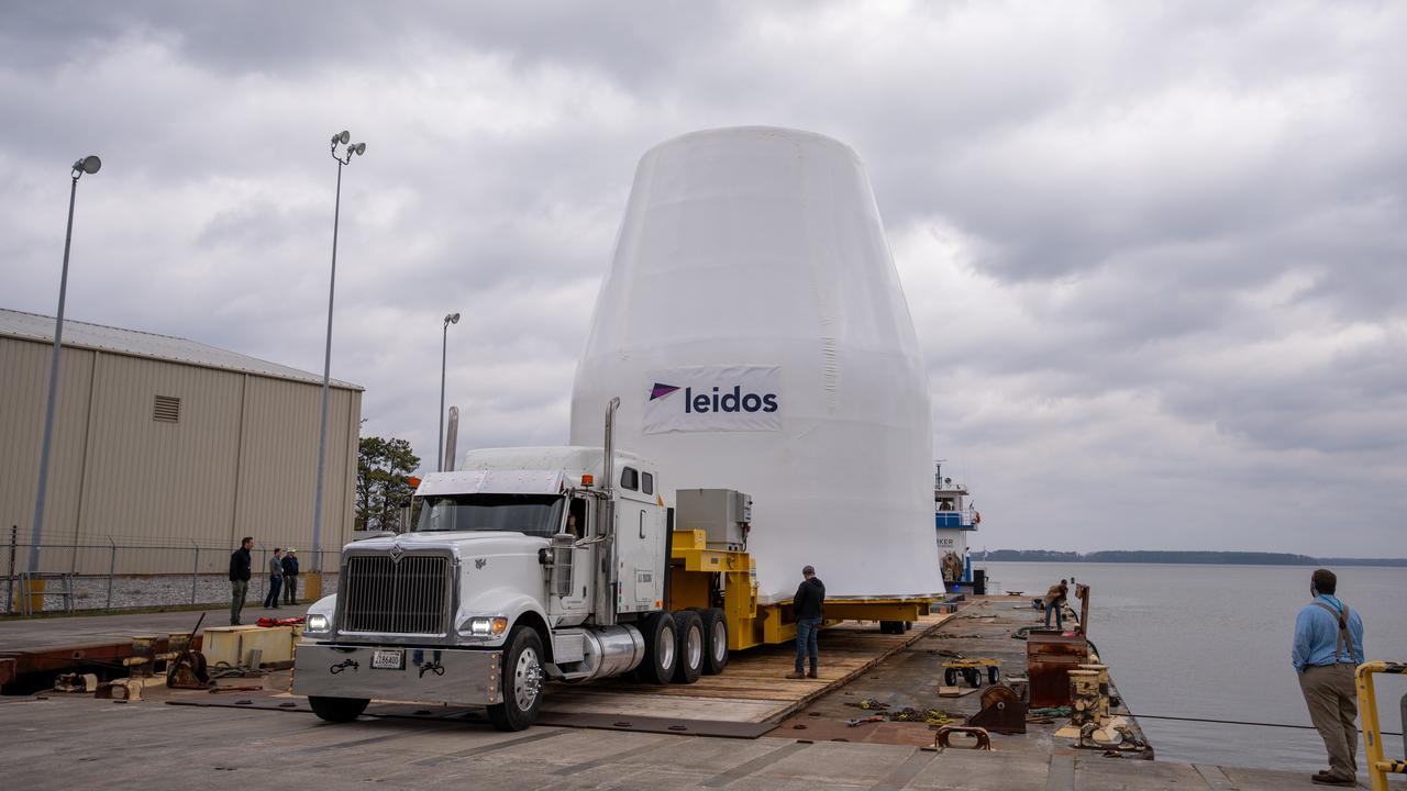
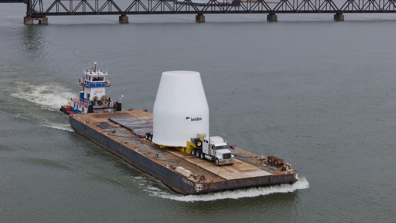
Evolved adapter for NASA SLS rocket readied for testing at Marshall These photos and videos show how crews guided a test version of the universal stage adapter for NASA’s more powerful version of its SLS (Space Launch System) rocket to Building 4619 at the agency’s Marshall Space Flight Center in Huntsville, Alabama, Feb. 22. Built by Leidos, the lead contractor for the universal stage adapter, crews transported the hardware from a Leidos facility in Decatur, Alabama, the same day. The universal stage adapter will connect the SLS rocket’s upgraded in-space propulsion stage, called the exploration upper stage, to NASA’s Orion spacecraft as part of the evolved Block 1B configuration of the SLS rocket. It will also serve as a compartment capable of accommodating large payloads, such as modules or other exploration spacecraft. In Building 4619’s Load Test Annex High Bay at Marshall, the development test article will first undergo modal testing that will shake the hardware to validate dynamic models. Later, during ultimate load testing, force will be applied vertically and to the sides of the hardware. Unlike the flight hardware, the development test article has flaws intentionally included in its design, which will help engineers verity that the flight adapter can withstand the extreme forces it will face during launch and flight.