Held in appendage deploy position, the Hubble Space Telescope's (HST's) high gain antenna (HGA) has been released from its stowed position along the Support System Module (SSM) forward shell. The STS-31 crew aboard Discovery, Orbiter Vehicle (OV) oversees the automatic HGA deployment prior to releasing HST. HST HGA is backdropped against the blackness of space.
NASA Wide-field Infrared Survey Explorer spacecraft is situated on a work stand. At left on the spacecraft is the fixed panel solar array. In front, the square is the HGA Slotted Array Ku-Band.
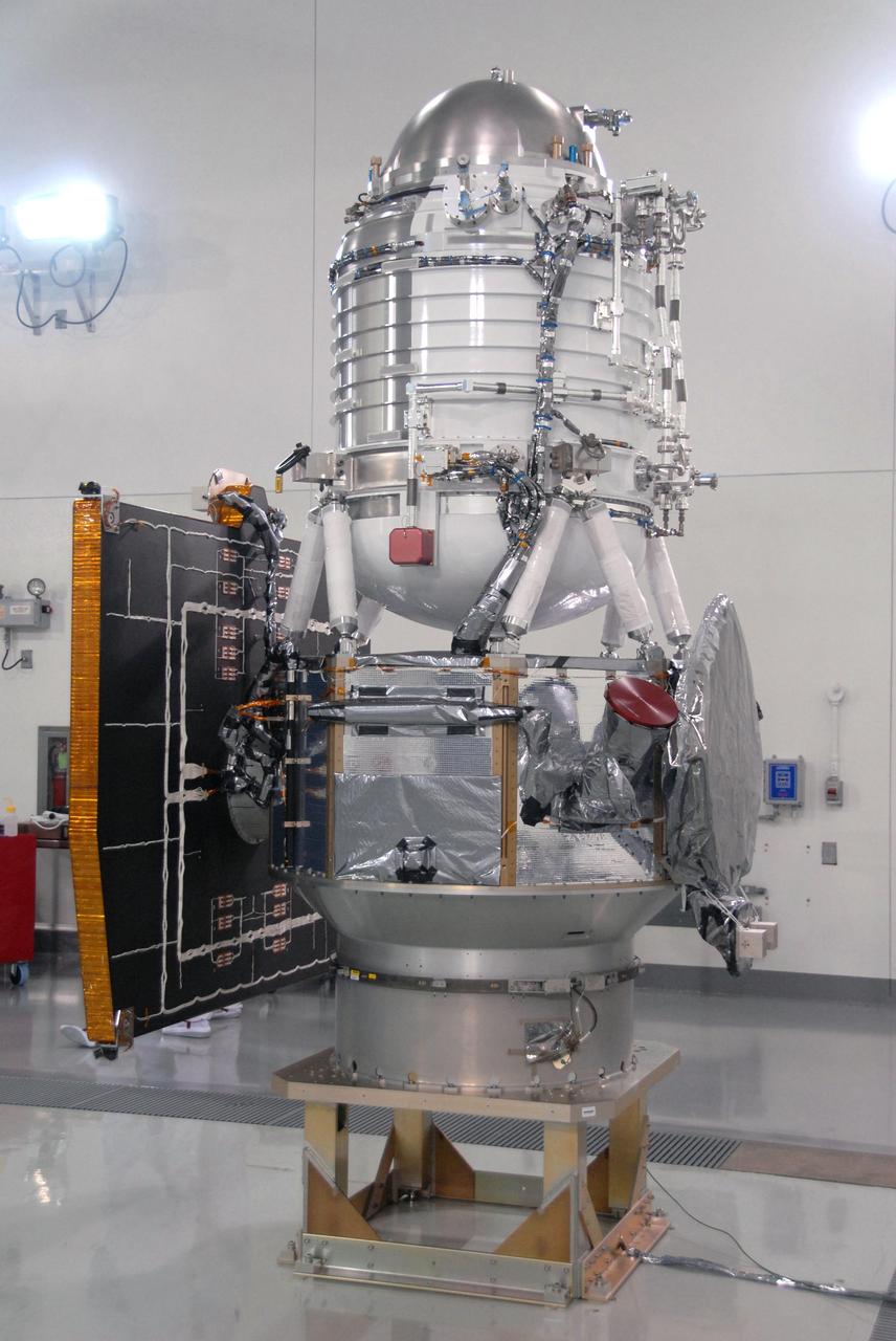
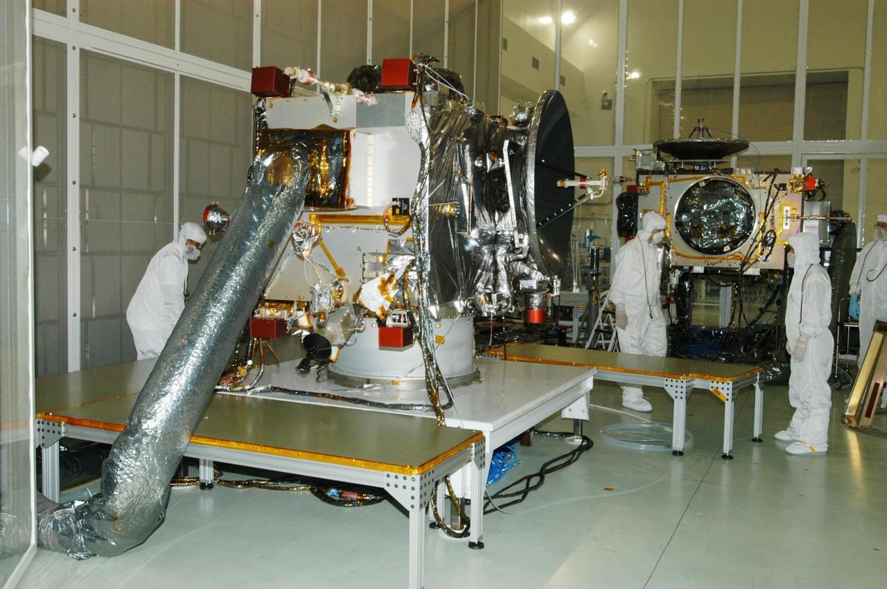
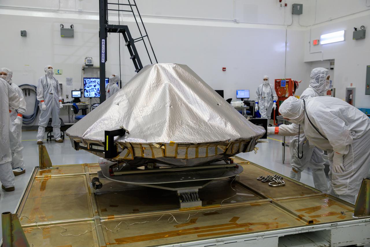
The GPM High Gain Antenna System (HGAS) in integration and testing at Goddard Space Flight Center. Credit: Craig E. Huber, Chief Engineer SGT Inc, NASA Goddard Space Flight Center The Global Precipitation Measurement (GPM) mission is an international partnership co-led by NASA and the Japan Aerospace Exploration Agency (JAXA) that will provide next-generation global observations of precipitation from space. GPM will study global rain, snow and ice to better understand our climate, weather, and hydrometeorological processes. As of Novermber 2013 the GPM Core Observatory is in the final stages of testing at NASA Goddard Space Flight Center. The satellite will be flown to Japan in the fall of 2013 and launched into orbit on an HII-A rocket in early 2014. For more on the GPM mission, visit <a href="http://gpm.gsfc.nasa.gov/" rel="nofollow">gpm.gsfc.nasa.gov/</a>. <b><a href="http://www.nasa.gov/audience/formedia/features/MP_Photo_Guidelines.html" rel="nofollow">NASA image use policy.</a></b> <b><a href="http://www.nasa.gov/centers/goddard/home/index.html" rel="nofollow">NASA Goddard Space Flight Center</a></b> enables NASA’s mission through four scientific endeavors: Earth Science, Heliophysics, Solar System Exploration, and Astrophysics. Goddard plays a leading role in NASA’s accomplishments by contributing compelling scientific knowledge to advance the Agency’s mission. <b>Follow us on <a href="http://twitter.com/NASA_GoddardPix" rel="nofollow">Twitter</a></b> <b>Like us on <a href="http://www.facebook.com/pages/Greenbelt-MD/NASA-Goddard/395013845897?ref=tsd" rel="nofollow">Facebook</a></b> <b>Find us on <a href="http://instagram.com/nasagoddard?vm=grid" rel="nofollow">Instagram</a></b>
The Hubble Space Telescope (HST), grappled by Discovery's, Orbiter Vehicle (OV) 103's, remote manipulator system (RMS), is held in a pre-deployment position. During STS-31 checkout procedures, the solar array (SA) panels and the high gain antennae (HGA) will be deployed. The starboard SA (center) and the two HGA are stowed along side the Support System Module (SSM) forward shell. The sun highlights HST against the blackness of space.
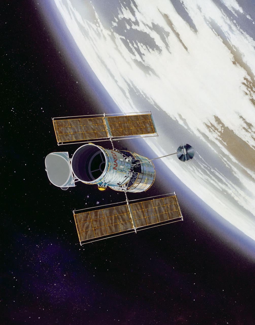
This artist concept shows the Hubble Space Telescope (HST) in operational configuration orbiting the Earth after its deploy from Discovery, Orbiter Vehicle (OV) 103 during STS-31. The high gain antennas (HGAs) and solar arrays (SAs) have been extended. HST's aperature door is open as it views the universe from a vantage point above the Earth's atmosphere. View provided by the Marshall Space Flight Center (MSFC).
The Hubble Space Telescope (HST), grappled by Discovery's, Orbiter Vehicle (OV) 103's, remote manipulator system (RMS), is oriented in a 90 degree pitch position during STS-31 pre-deployment checkout procedures. The solar array (SA) panel (center) and high gain antennae (HGA) (on either side) are stowed along the Support System Module (SSM) forward shell prior to deployment. The sun highlights HST against the blackness of space.
The Hubble Space Telescope (HST) is raised above the payload bay (PLB) in low hover position during STS-31 checkout and pre-deployment procedures aboard Discovery, Orbiter Vehicle (OV) 103. Stowed along the HST Support System Module (SSM) are the high gain antenna (HGA) (center) and the two solar arrays (one either side). In the background are the orbital maneuvering system (OMS) pods and the Earth's surface.
During STS-31 checkout, the Hubble Space Telescope (HST) is held in a pre-deployment position by Discovery's, Orbiter Vehicle (OV) 103's, remote manipulator system (RMS). The view, taken from the crew cabin overhead window W7, shows the starboard solar array (SA) panel (center) and two high gain antennae (HGA) (on either side) stowed along side the Support System Module (SSM) forward shell. The sun highlights HST against the blackness of space.
View taken through overhead window W7 aboard Discovery, Orbiter Vehicle (OV) 103, shows the Hubble Space Telescope (HST) grappled by the remote manipulator system (RMS) and held in a 90 degree pitch position against the blackness of space. The solar array (SA) panel (center) and the high gain antennae (HGA) (on either side) are visible along the Support System Module (SSM) forward shell prior to deployment during STS-31.
KENNEDY SPACE CENTER, FLA. - At Astrotech Space Operations in Titusville, Fla., the two STEREO spacecraft are being prepared for installation of the solar arrays. In the foreground is spacecraft "B," sitting as it would on the rocket. Pointing to the right is the high gain antenna (HGA), which is used to get science data at high data rates back to Earth. In the background is the "A" observatory, rotated horizontally on a Ransome table so that its HGA is pointing upward. The black circle facing forward is the primary instrument Sun Earth Connection Coronal and Heliospheric Investigation (SECCHI), a suite of remote sensing instruments to image solar flares, with a protective cover that is removed before flight. STEREO consists of two spacecraft whose mission is the first to take measurements of the sun and solar wind in 3-D. This new view will improve our understanding of space weather and its impact on the Earth. Preparations are under way for a liftoff aboard a Delta rocket no earlier than July 22. Photo credit: NASA/George Shelton
During STS-31, the Hubble Space Telescope (HST) grappled by the remote manipulator system (RMS) end effector is held in appendage deploy position above Discovery, Orbiter Vehicle (OV) 103. The solar array (SA) bistem cassette has been released from its latch fittings. The bistem spreader bars begin to unfurl the SA wing. The secondary deployment mechanism (SDM) handle is visible at the SA end. Stowed against either side of the HST System Support Module (SSM) forward shell are the high-gain antennae (HGA). Puerto Rico and the Dominican Republic are recognizable at the left of the frame.

VANDENBERG AIR FORCE BASE, Calif. -- At Vandenberg Air Force Base's Astrotech processing facility in California, NASA's Wide-field Infrared Survey Explorer, or WISE, spacecraft is situated on a work stand. At left on the spacecraft is the fixed panel solar array. In front, the square is the HGA Slotted Array (Ku-Band). The satellite will survey the entire sky at infrared wavelengths, creating a cosmic clearinghouse of hundreds of millions of objects, which will be catalogued, providing a vast storehouse of knowledge about the solar system, the Milky Way, and the universe. Launch is scheduled no earlier than Dec. 10. Photo credit: NASA/Moore, VAFB
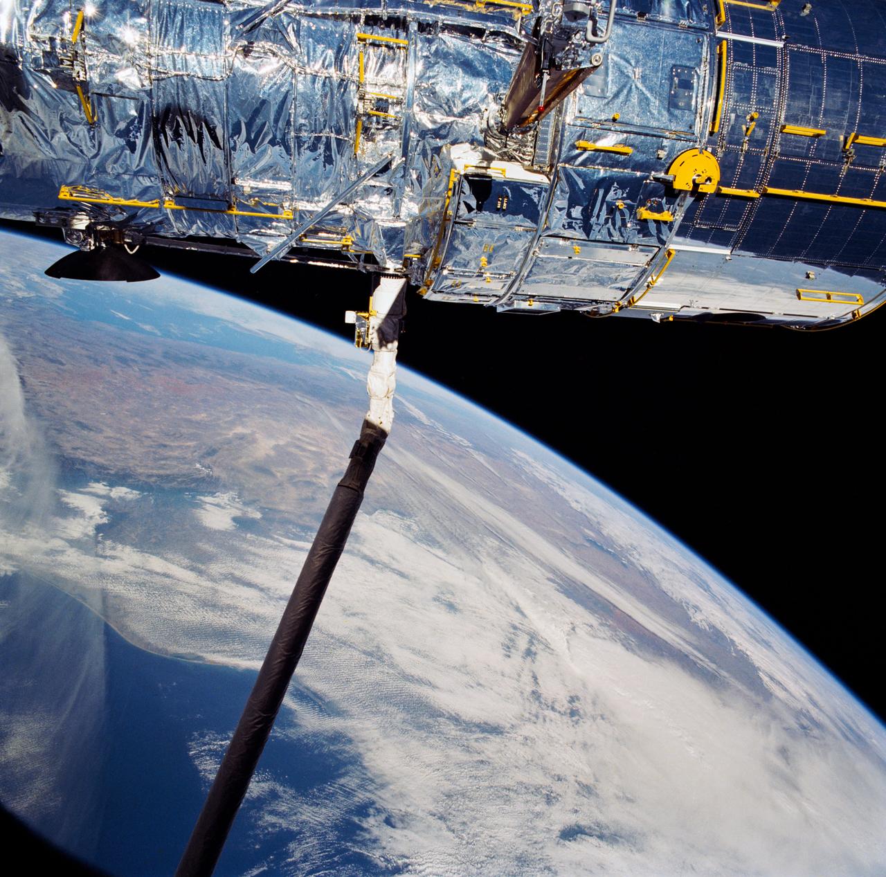
During STS-31, the Hubble Space Telescope (HST) is held in appendage deploy position by Discovery's, Orbiter Vehicle (OV) 103's, remote manipulator system (RMS) above the payload bay (PLB) and crew compartment cabin. While in this position the solar array (SA) wing bistem cassette (HST center) is deployed from its stowed location along side the Support System Module (SSM) forward shell. A high gain antenna (HGA) remains stowed along the SSM. The Earth's surface and the Earth limb creates a dramatic backdrop.
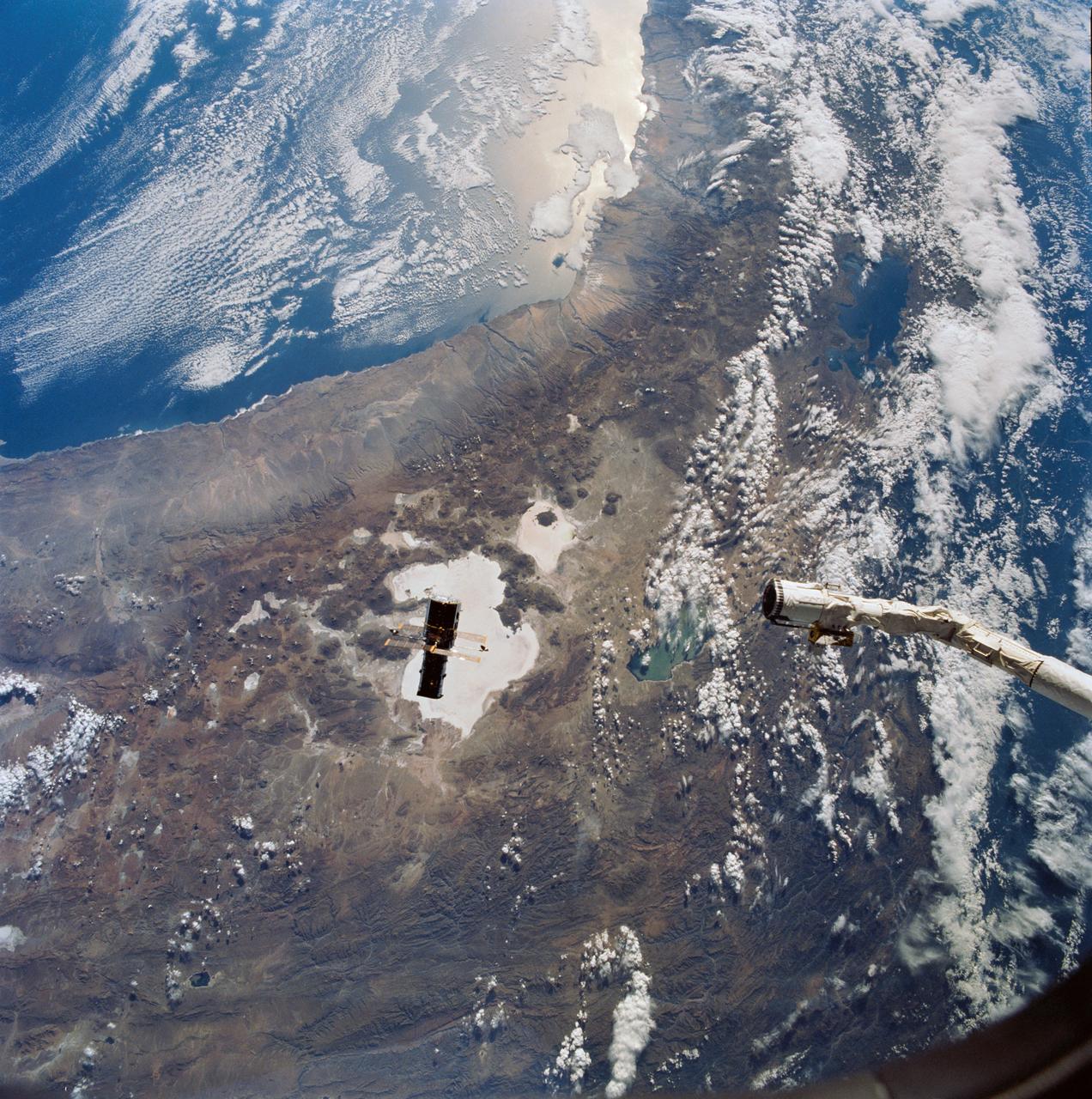
Hubble Space Telescope (HST), with its solar array (SA) wings and high gain antennae (HGA) fully extended,is released from Discovery's, Orbiter Vehicle (OV) 103's, remote manipulator system (RMS) end effector and is set free into Earth orbit by the STS-31 crew. HST drifts away from the end effector over the Andes Mountains.Parts of Bolivia, Peru, Chile, and Argentina are visible. The view covers a huge area of the western half of South America stretching from 14 degrees south latitude to 23 degrees, about 1,000 kilometers.
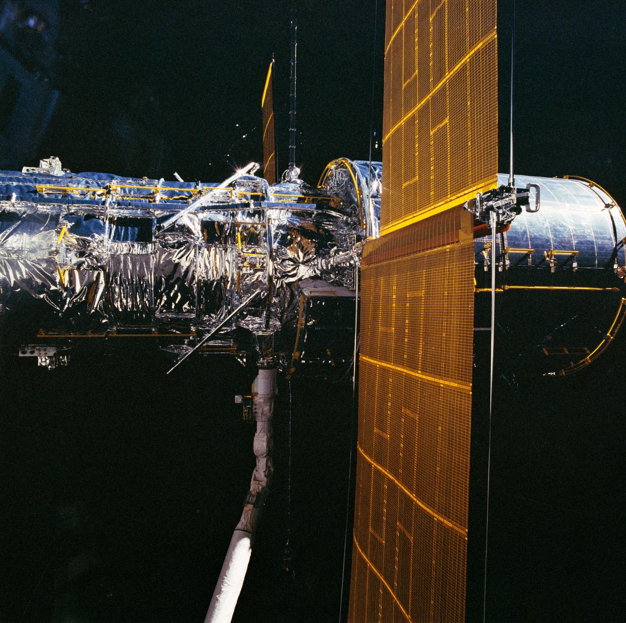
During STS-31, the Hubble Space Telescope (HST), grappled by the remote manipulator system (RMS) end effector, is held against the blackness of space. The two solar array (SA) wings (large gold panels) are fully extended with bistem cassette and secondary deployment mechanism (SDM) handle clearly visible. The two deployed high gain antennae (HGA) masts are parallel to the SA panels. RMS end effector is positioned on the starboard fixture during the predeployment checkout operations above Discovery's, Orbiter Vehicle (OV) 103's, payload bay (PLB).
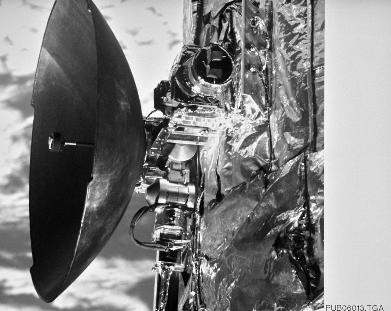
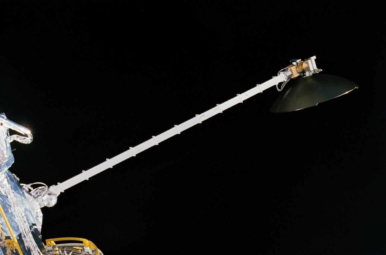
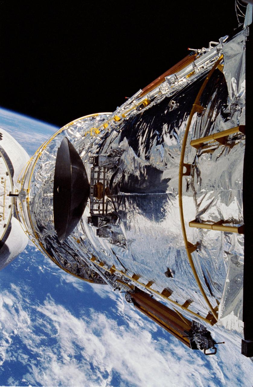
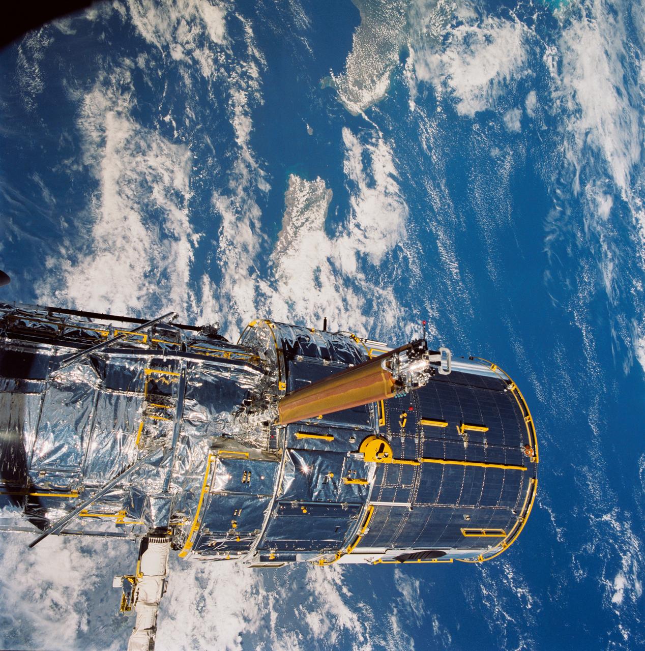
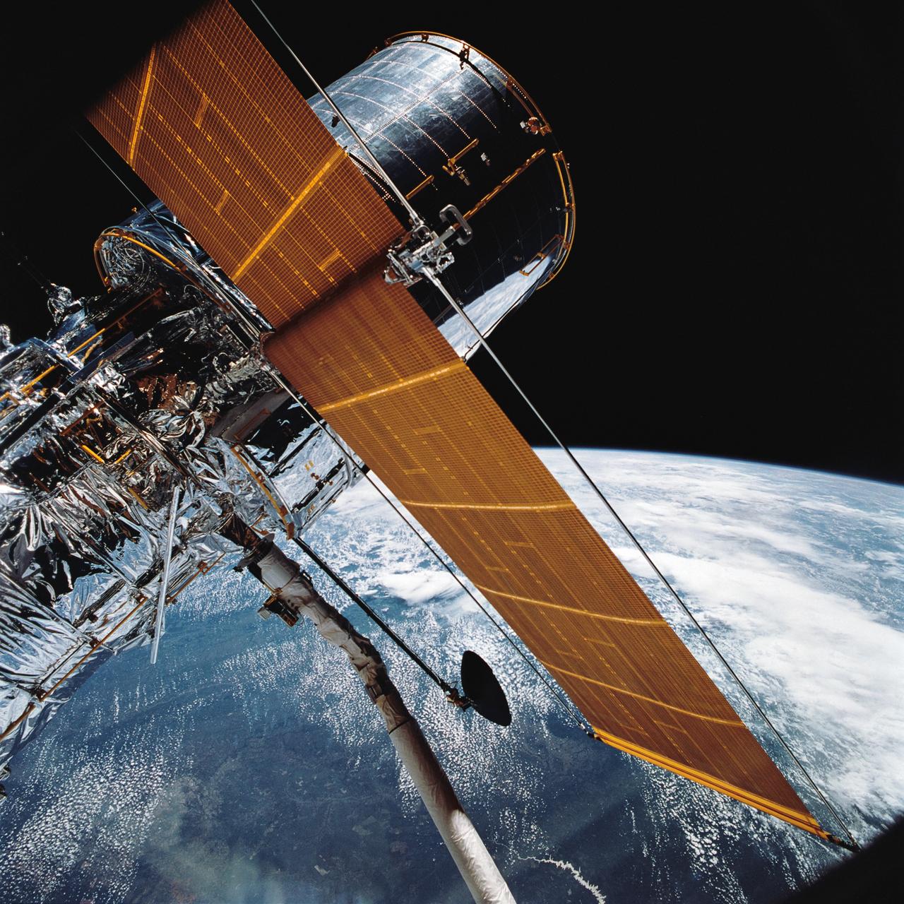
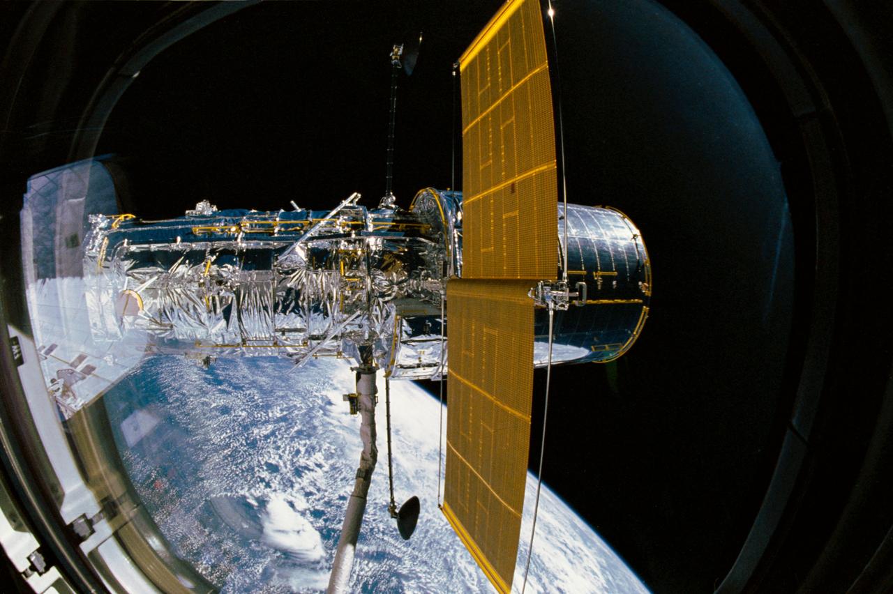
S61-E-021 (7 Dec 1993) --- This close-up view of one of two High Gain Antennae (HGA) on the Hubble Space Telescope (HST) was photographed with an Electronic Still Camera (ESC), and down linked to ground controllers soon afterward. Endeavour's crew captured the HST on December 4, 1993 in order to service the telescope over a period of five days. Four of the crew members have been working in alternating pairs outside Endeavour's shirt sleeve environment to service the giant telescope. Electronic still photography is a relatively new technology which provides the means for a handheld camera to electronically capture and digitize an image with resolution approaching film quality. The electronic still camera has flown as an experiment on several other shuttle missions.
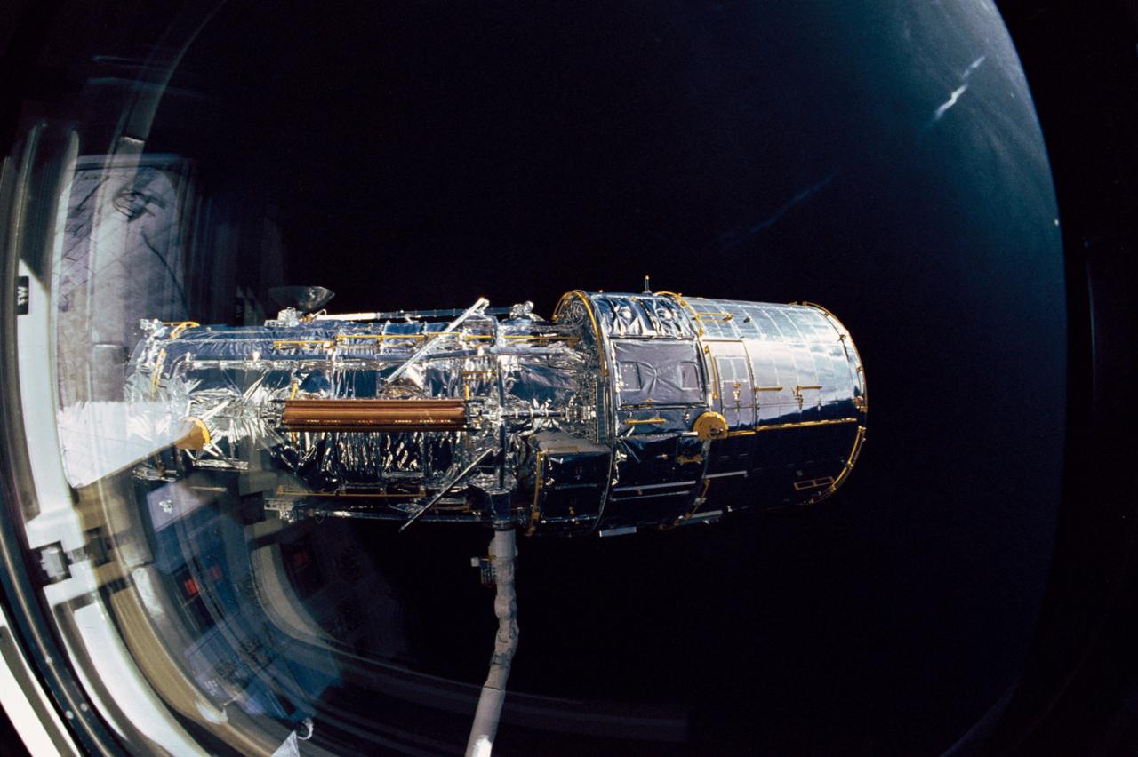
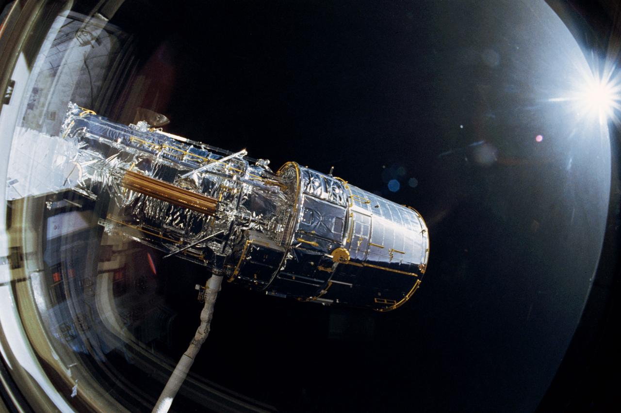
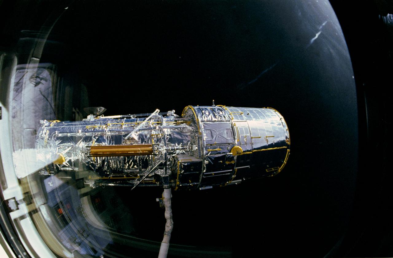
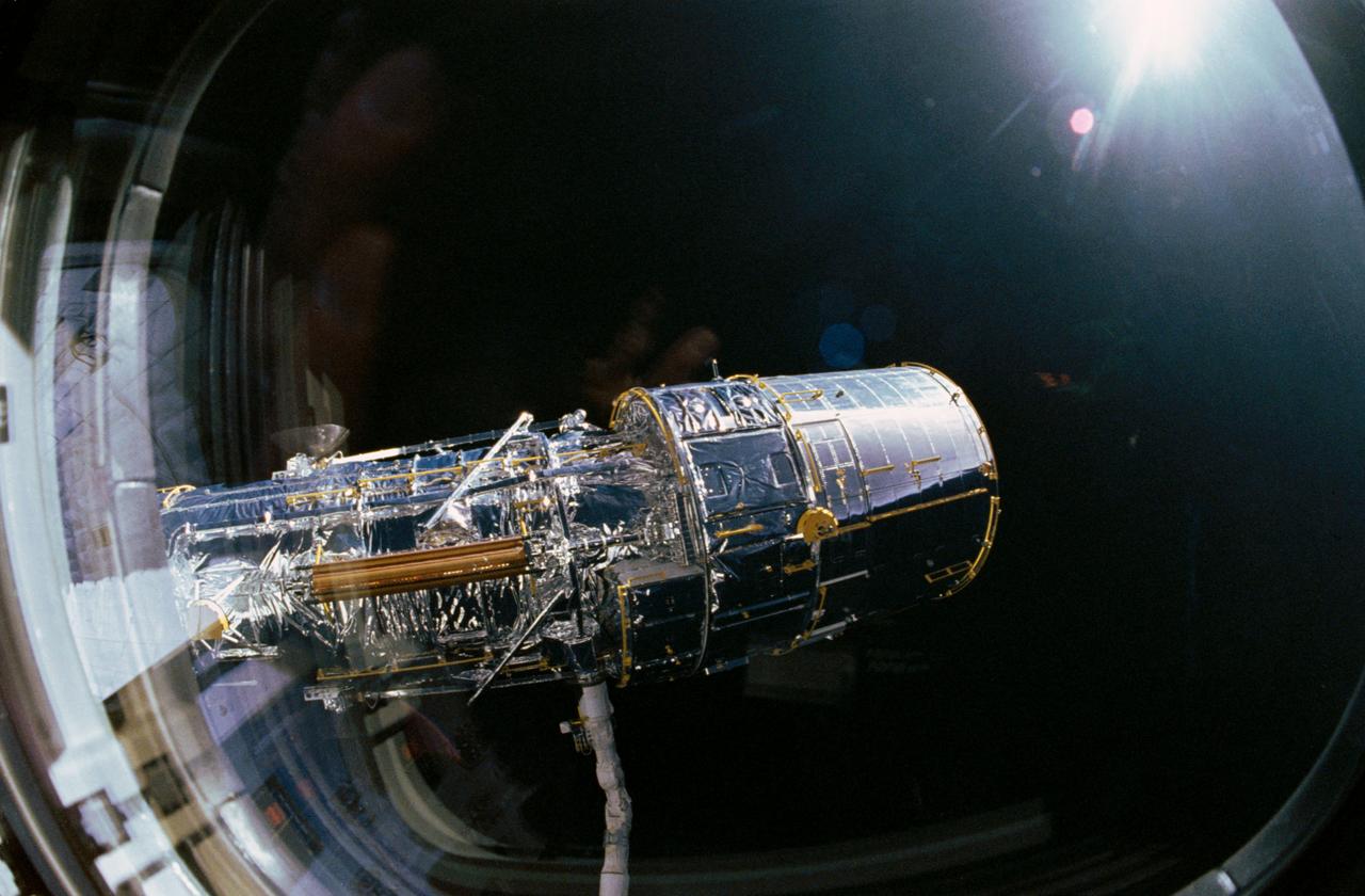
S61-E-009 (4 Dec 1993) --- This view of one of two High Gain Antennae (HGA) on the Hubble Space Telescope (HST) was photographed with an Electronic Still Camera (ESC). The scene was down linked to ground controllers soon after the Space Shuttle Endeavour caught up to the orbiting telescope 320 miles above Earth. Shown here before grapple, the HST was captured on December 4, 1993 in order to service the telescope. Over a period of five days, four of the seven STS-61 crew members will work in alternating pairs outside Endeavour's shirt sleeve environment. Electronic still photography is a relatively new technology which provides the means for a handheld camera to electronically capture and digitize an image with resolution approaching film quality. The electronic still camera has flown as an experiment on several other shuttle missions.

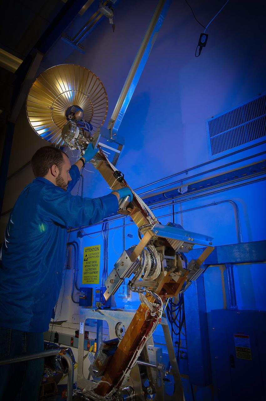
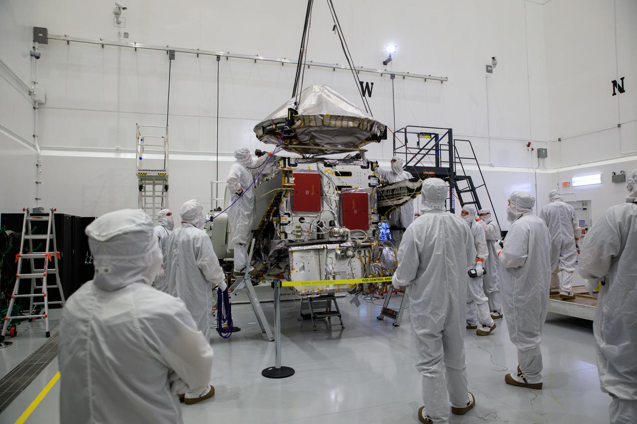
Inside the Astrotech Space Operations Facility in Titusville, Florida, the high gain antenna for NASA’s Lucy spacecraft is lifted by crane on Aug. 6, 2021. The antenna will be installed on Lucy. Lucy is scheduled to launch no earlier than Saturday, Oct. 16, on a United Launch Alliance Atlas V 401 rocket from Launch Pad 41 at Cape Canaveral Space Force Station. NASA’s Launch Services Program based at Kennedy Space Center is managing the launch. Over its 12-year primary mission, Lucy will explore a record-breaking number of asteroids, flying by one asteroid in the solar system’s main belt and seven Trojan asteroids. Additionally, Lucy’s path will circle back to Earth three times for gravity assists, making it the first spacecraft ever to return to the vicinity of Earth from the outer solar system.
Workers assist as a crane lowers the high gain antenna for installation on NASA’s Lucy spacecraft inside the Astrotech Space Operations Facility in Titusville, Florida, on Aug. 6, 2021. Lucy is scheduled to launch no earlier than Saturday, Oct. 16, on a United Launch Alliance Atlas V 401 rocket from Launch Pad 41 at Cape Canaveral Space Force Station. NASA’s Launch Services Program based at Kennedy Space Center is managing the launch. Over its 12-year primary mission, Lucy will explore a record-breaking number of asteroids, flying by one asteroid in the solar system’s main belt and seven Trojan asteroids. Additionally, Lucy’s path will circle back to Earth three times for gravity assists, making it the first spacecraft ever to return to the vicinity of Earth from the outer solar system.
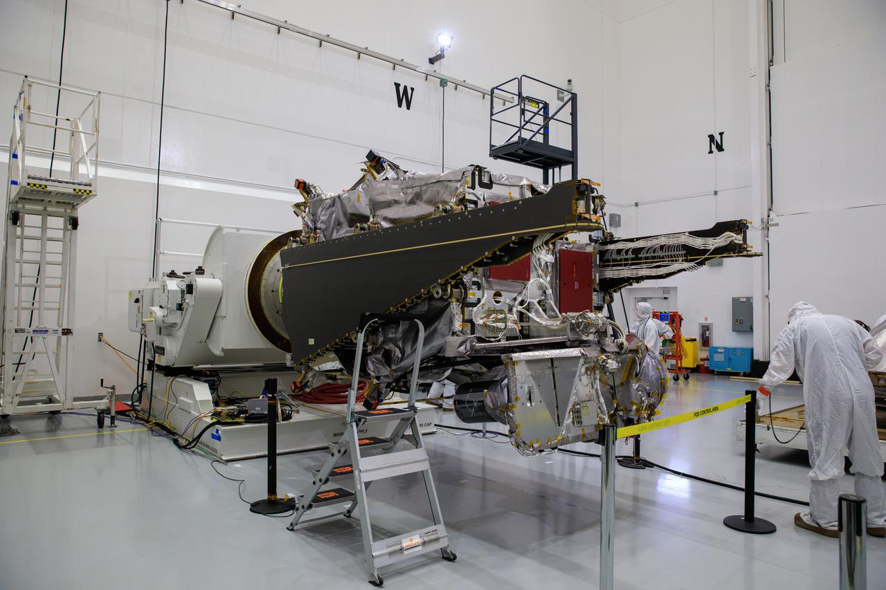
Workers inside the Astrotech Space Operations Facility in Titusville, Florida, prepare NASA’s Lucy spacecraft for installation of the high gain antenna on Aug. 6, 2021. Lucy is scheduled to launch no earlier than Saturday, Oct. 16, on a United Launch Alliance Atlas V 401 rocket from Launch Pad 41 at Cape Canaveral Space Force Station. NASA’s Launch Services Program based at Kennedy Space Center is managing the launch. Over its 12-year primary mission, Lucy will explore a record-breaking number of asteroids, flying by one asteroid in the solar system’s main belt and seven Trojan asteroids. Additionally, Lucy’s path will circle back to Earth three times for gravity assists, making it the first spacecraft ever to return to the vicinity of Earth from the outer solar system.
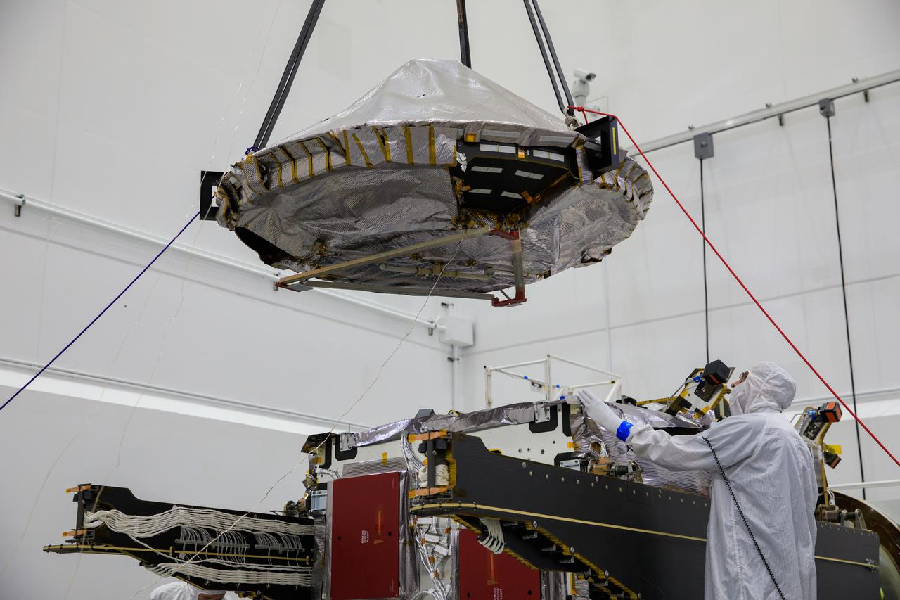
Workers assist as a crane lowers the high gain antenna for installation on NASA’s Lucy spacecraft inside the Astrotech Space Operations Facility in Titusville, Florida, on Aug. 6, 2021. Lucy is scheduled to launch no earlier than Saturday, Oct. 16, on a United Launch Alliance Atlas V 401 rocket from Launch Pad 41 at Cape Canaveral Space Force Station. NASA’s Launch Services Program based at Kennedy Space Center is managing the launch. Over its 12-year primary mission, Lucy will explore a record-breaking number of asteroids, flying by one asteroid in the solar system’s main belt and seven Trojan asteroids. Additionally, Lucy’s path will circle back to Earth three times for gravity assists, making it the first spacecraft ever to return to the vicinity of Earth from the outer solar system.
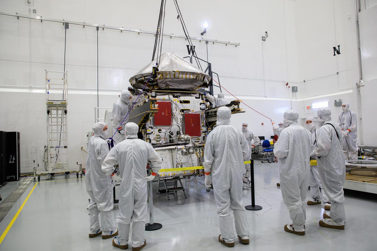
Workers assist as a crane lowers the high gain antenna for installation on NASA’s Lucy spacecraft inside the Astrotech Space Operations Facility in Titusville, Florida, on Aug. 6, 2021. Lucy is scheduled to launch no earlier than Saturday, Oct. 16, on a United Launch Alliance Atlas V 401 rocket from Launch Pad 41 at Cape Canaveral Space Force Station. NASA’s Launch Services Program based at Kennedy Space Center is managing the launch. Over its 12-year primary mission, Lucy will explore a record-breaking number of asteroids, flying by one asteroid in the solar system’s main belt and seven Trojan asteroids. Additionally, Lucy’s path will circle back to Earth three times for gravity assists, making it the first spacecraft ever to return to the vicinity of Earth from the outer solar system.
Workers inside the Astrotech Space Operations Facility in Titusville, Florida, prepare the high gain antenna for installation on NASA’s Lucy spacecraft on Aug. 6, 2021. Lucy is scheduled to launch no earlier than Saturday, Oct. 16, on a United Launch Alliance Atlas V 401 rocket from Launch Pad 41 at Cape Canaveral Space Force Station. NASA’s Launch Services Program based at Kennedy Space Center is managing the launch. Over its 12-year primary mission, Lucy will explore a record-breaking number of asteroids, flying by one asteroid in the solar system’s main belt and seven Trojan asteroids. Additionally, Lucy’s path will circle back to Earth three times for gravity assists, making it the first spacecraft ever to return to the vicinity of Earth from the outer solar system.
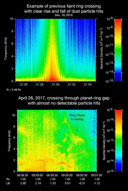
The sounds and spectrograms in these two videos represent data collected by the Radio and Plasma Wave Science, or RPWS, instrument on NASA's Cassini spacecraft, as it crossed the plane of Saturn's rings on two separate orbits. As tiny, dust-sized particles strike Cassini and the three 33-foot-long (10-meter-long), RPWS antennas, the particles are vaporized into tiny clouds of plasma, or electrically excited gas. These tiny explosions make a small electrical signal (a voltage impulse) that RPWS can detect. Researchers on the RPWS team convert the data into visible and audio formats, like those seen here, for analysis. Ring particle hits sound like pops and cracks in the audio. The first video (top image in the montage) was made using RPWS data from a ring plane crossing on Dec. 18, 2016, when the spacecraft passed through the faint, dusty Janus-Epimetheus ring (see PIA08328 for an image that features this ring). This was during Cassini's 253rd orbit of Saturn, known as Rev 253. As is typical for this sort of ring crossing, the number of audible pops and cracks rises to a maximum around the time of a ring crossing and trails off afterward. The peak of the ring density is obvious in the colored display at the red spike. The second video (bottom image in the montage) was made using data RPWS collected as Cassini made the first dive through the gap between Saturn and its rings as part of the mission's Grand Finale, on April 26, 2017. Very few pops and cracks are audible in this data at all. In comparing the two data sets, it is apparent that while Cassini detected many ring-particles striking Cassini when passing through the Janus-Epimetheus ring, the first Grand Finale crossing -- in stark contrast -- was nearly particle free. The unexpected finding that the gap is so empty is a new mystery that scientists are eager to understand. On April 26, 2017, Cassini dove through the previously unexplored ring-planet gap at speeds approaching 75,000 mph (121,000 kph), using its large, dish-shaped high-gain antenna (or HGA) as a shield to protect the rest of the spacecraft and its instruments from potential impacts by small, icy ring particles. Two of Cassini's instruments, the magnetometer and RPWS, extend beyond the protective antenna dish, and were exposed to the particle environment during the dive. The Cassini team used this data from RPWS, along with inputs from other components on the spacecraft, to make the decision of whether the HGA would be needed as a shield on most future Grand Finale dives through the planet-ring gap. Based on these inputs the team determined this protective measure would not be needed, allowing the team's preferred mode of science operations to proceed, with Cassini able to point its science instruments in any direction necessary to obtain scientists' desired observations. (Four of the 21 remaining dives pass through the inner D ring. The mission had already planned to use the HGA as a shield for those passes.) The colors on the spectrogram indicate the emitted power of the radio waves, with red as the most powerful. Time is on the x-axis, and frequency of the radio waves is on the y-axis. The audible whistle in the April 26 data, just before ring plane crossing, is due to a type of plasma wave that will be the subject of further study. In addition, there is an abrupt change beginning at the 09:00:00 mark on the spectrogram that represents a change in the RPWS antenna's operational configuration (from monopole mode to dipole mode). The videos can be viewed at https://photojournal.jpl.nasa.gov/catalog/PIA21446
STS031-76-026 (25 April 1990) --- Most of the giant Hubble Space Telescope (HST) can be seen as it is suspended in space by Discovery's Remote Manipulator System (RMS) following the deployment of part of its solar panels and antennae. The photo was taken with a handheld Hasselblad camera. This was among the first photos NASA released on April 30, 1990, from the five-day STS 31 mission.
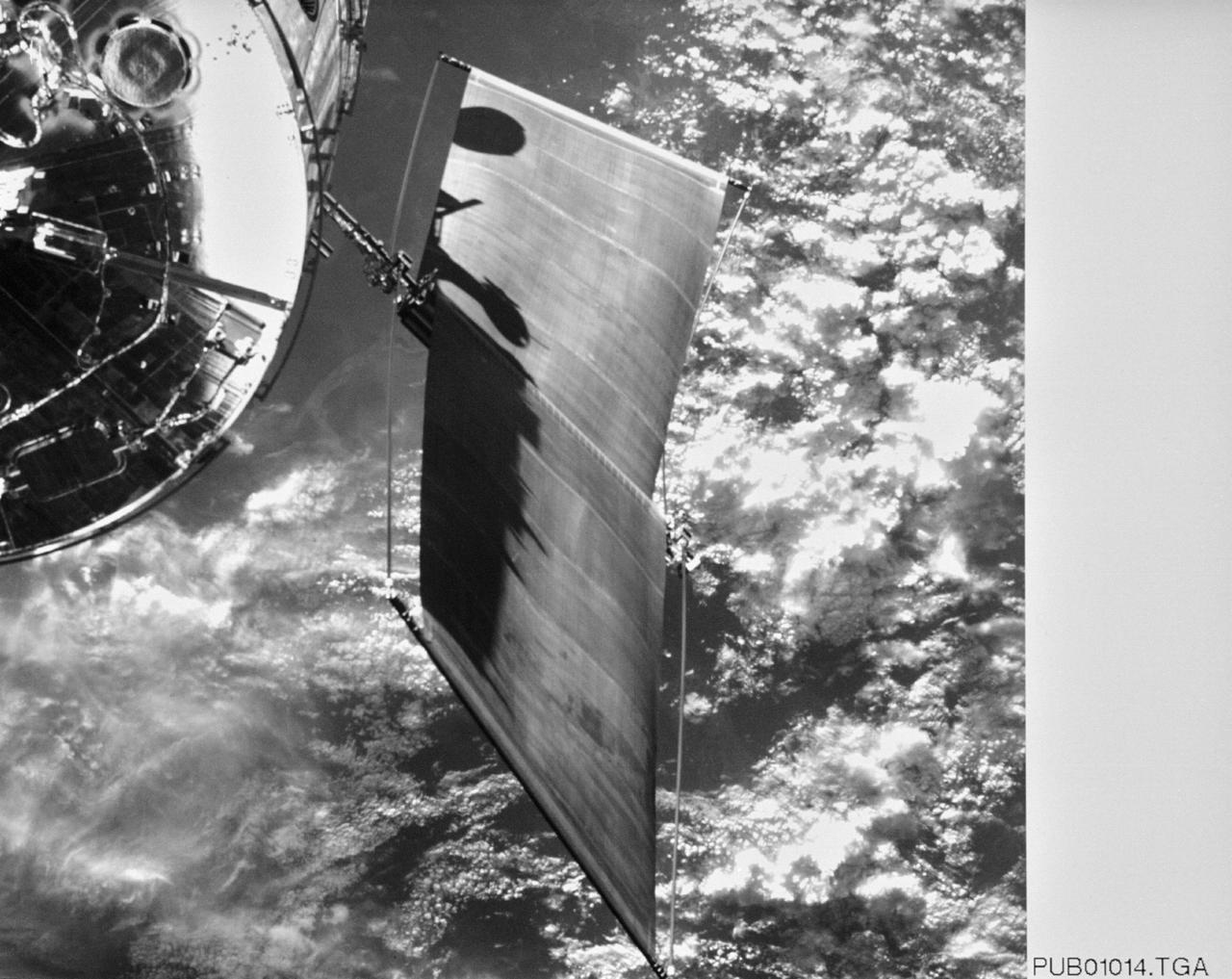
STS031-03-009 (25 April 1990) --- The Hubble Space Telescope (HST), still in the grasp of Discovery's remote manipulator system (RMS), is backdropped over Earth some 332 nautical miles below. In this scene, HST has deployed one of its solar array panels but is yet to have extended the second. This scene was captured with a 35mm camera aimed through an overhead window on the aft flight deck.
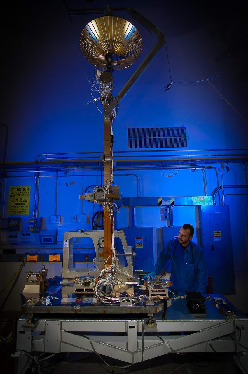
File: 03/26/2012 The GPM High Gain Antenna System (HGAS) in integration and testing at Goddard Space Flight Center. GPM is a joint mission between NASA and the Japan Aerospace Exploration Agency (JAXA). The Core Observatory will link data from a constellation of current and planned satellites to produce next-generation global measurements of rainfall and snowfall from space. The GPM mission is the first coordinated international satellite network to provide near real-time observations of rain and snow every three hours anywhere on the globe. The GPM Core Observatory anchors this network by providing observations on all types of precipitation. The observatory's data acts as the measuring stick by which partner observations can be combined into a unified data set. The data will be used by scientists to study climate change, freshwater resources, floods and droughts, and hurricane formation and tracking. Credit: Craig E. Huber, Chief Engineer SGT Inc, NASA Goddard Space Flight Center <b><a href="http://www.nasa.gov/audience/formedia/features/MP_Photo_Guidelines.html" rel="nofollow">NASA image use policy.</a></b> <b><a href="http://www.nasa.gov/centers/goddard/home/index.html" rel="nofollow">NASA Goddard Space Flight Center</a></b> enables NASA’s mission through four scientific endeavors: Earth Science, Heliophysics, Solar System Exploration, and Astrophysics. Goddard plays a leading role in NASA’s accomplishments by contributing compelling scientific knowledge to advance the Agency’s mission. <b>Follow us on <a href="http://twitter.com/NASAGoddardPix" rel="nofollow">Twitter</a></b> <b>Like us on <a href="http://www.facebook.com/pages/Greenbelt-MD/NASA-Goddard/395013845897?ref=tsd" rel="nofollow">Facebook</a></b> <b>Find us on <a href="http://instagram.com/nasagoddard?vm=grid" rel="nofollow">Instagram</a></b>