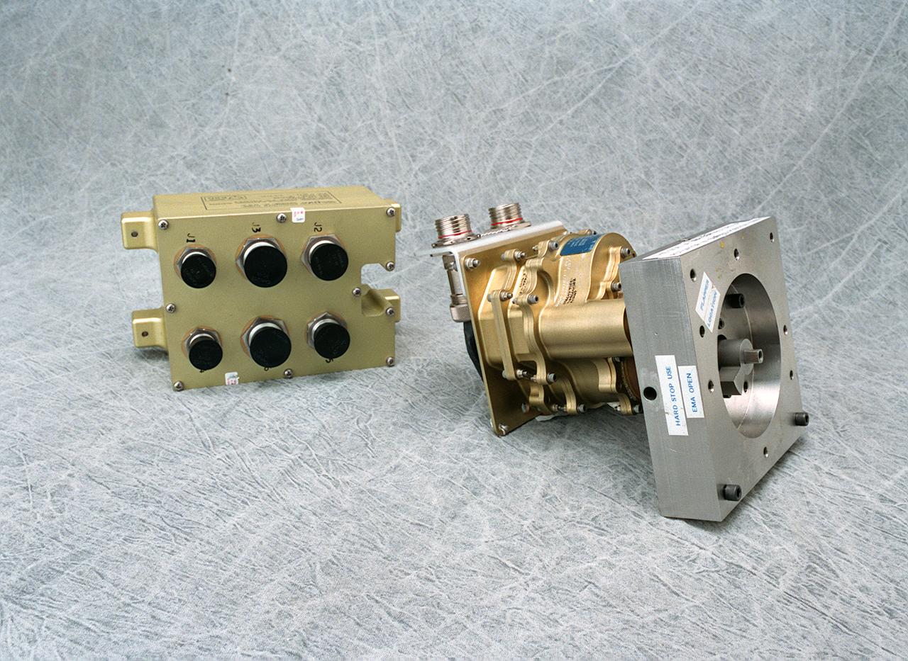
The electro-mechanical actuator, a new electronics technology, is an electronic system that provides the force needed to move valves that control the flow of propellant to the engine. It is proving to be advantageous for the main propulsion system plarned for a second generation reusable launch vehicle. Hydraulic actuators have been used successfully in rocket propulsion systems. However, they can leak when high pressure is exerted on such a fluid-filled hydraulic system. Also, hydraulic systems require significant maintenance and support equipment. The electro-mechanical actuator is proving to be low maintenance and the system weighs less than a hydraulic system. The electronic controller is a separate unit powering the actuator. Each actuator has its own control box. If a problem is detected, it can be replaced by simply removing one defective unit. The hydraulic systems must sustain significant hydraulic pressures in a rocket engine regardless of demand. The electro-mechanical actuator utilizes power only when needed. A goal of the Second Generation Reusable Launch Vehicle Program is to substantially improve safety and reliability while reducing the high cost of space travel. The electro-mechanical actuator was developed by the Propulsion Projects Office of the Second Generation Reusable Launch Vehicle Program at the Marshall Space Flight Center.
The flexwall section of NASA Glenn’s 10x10 supersonic wind tunnel is made up of two movable flexible steel sidewalls. These powerful hydraulic jacks move the walls in and out to control supersonic air speeds in the test section between Mach 2.0 and 3.5.
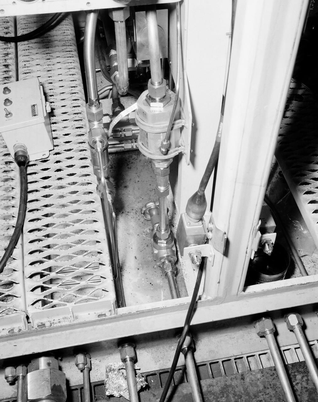
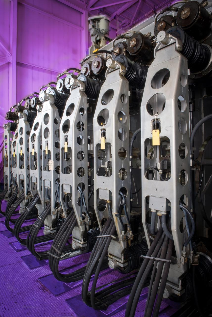
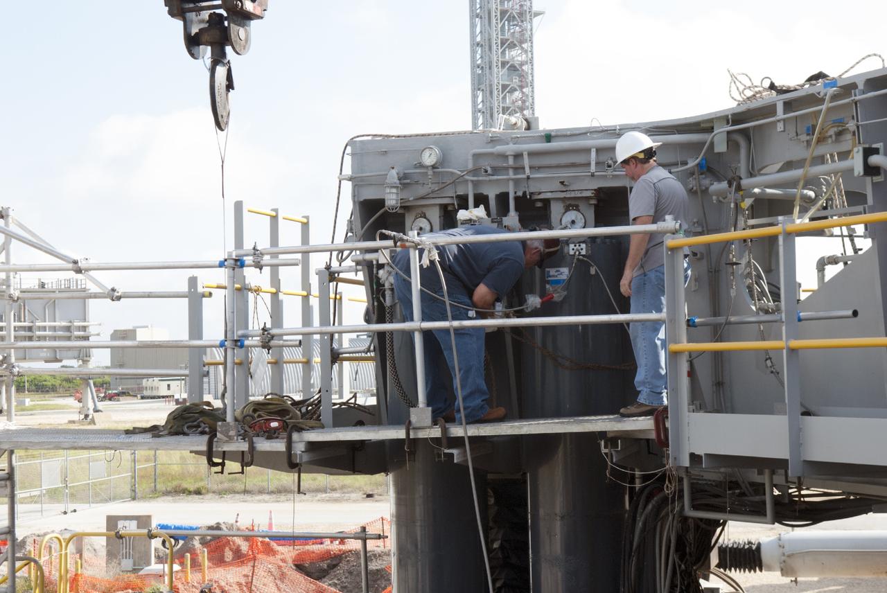
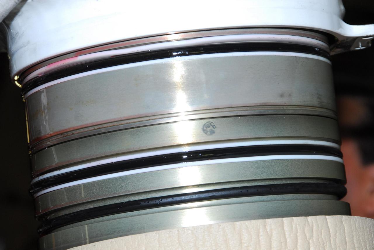
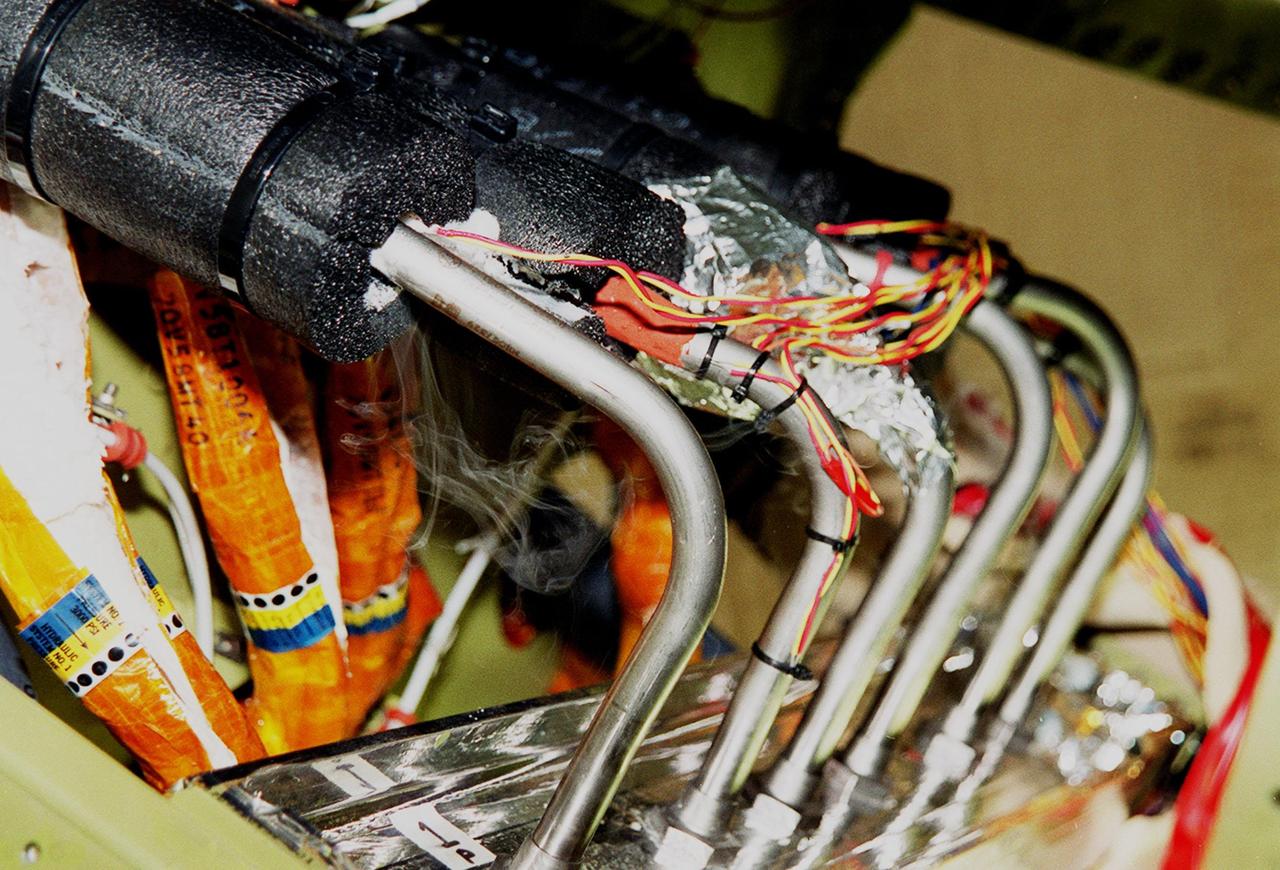
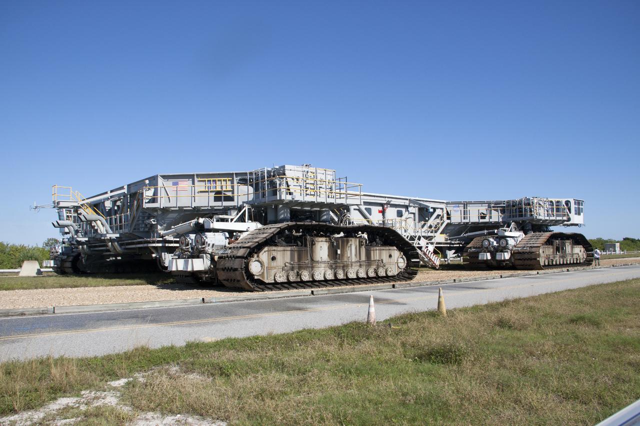
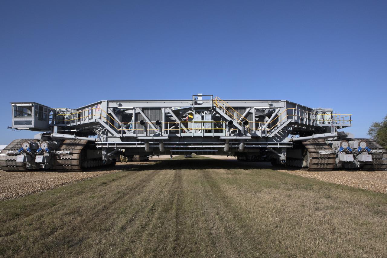
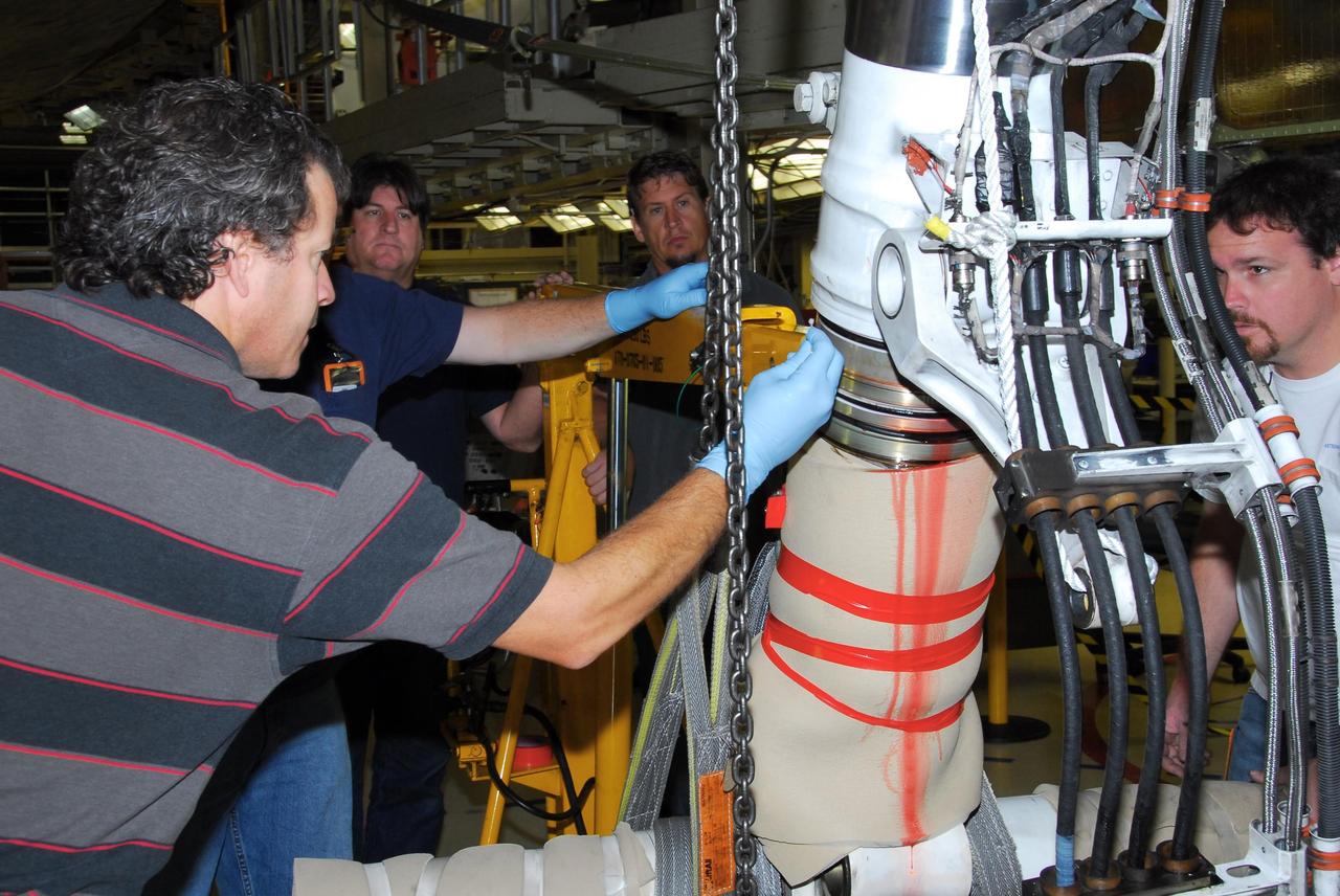
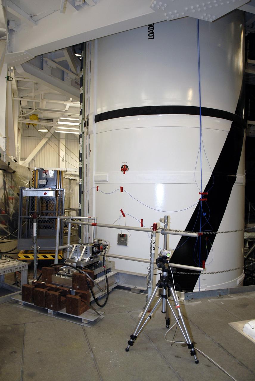
The Marshall Space Flight Center (MSFC) played a crucial role in the development of the huge Saturn rockets that delivered humans to the moon in the 1960s. Many unique facilities existed at MSFC for the development and testing of the Saturn rockets. Affectionately nicknamed “The Arm Farm”, the Random Motion/ Lift-Off Simulator was one of those unique facilities. This facility was developed to test the swing arm mechanisms that were used to hold the rocket in position until liftoff. The Arm Farm provided the capability of testing the detachment and reconnection of various arms under brutally realistic conditions. The 18-acre facility consisted of more than a half dozen arm test positions and one position for testing access arms used by the Apollo astronauts. Each test position had two elements: a vehicle simulator for duplicating motions during countdown and launch; and a section duplicating the launch tower. The vehicle simulator duplicated the portion of the vehicle skin that contained the umbilical connections and personnel access hatches. Driven by a hydraulic servo system, the vehicle simulator produced relative motion between the vehicle and tower. On the Arm Farm, extreme environmental conditions (such as a launch scrub during an approaching Florida thunderstorm) could be simulated. The dramatic scenes that the Marshall engineers and technicians created at the Arm Farm permitted the gathering of crucial technical and engineering data to ensure a successful real time launch from the Kennedy Space Center. This photo depicts a close up view of the S-IV-B aft swing arm hydraulic with drain system orifice valve.
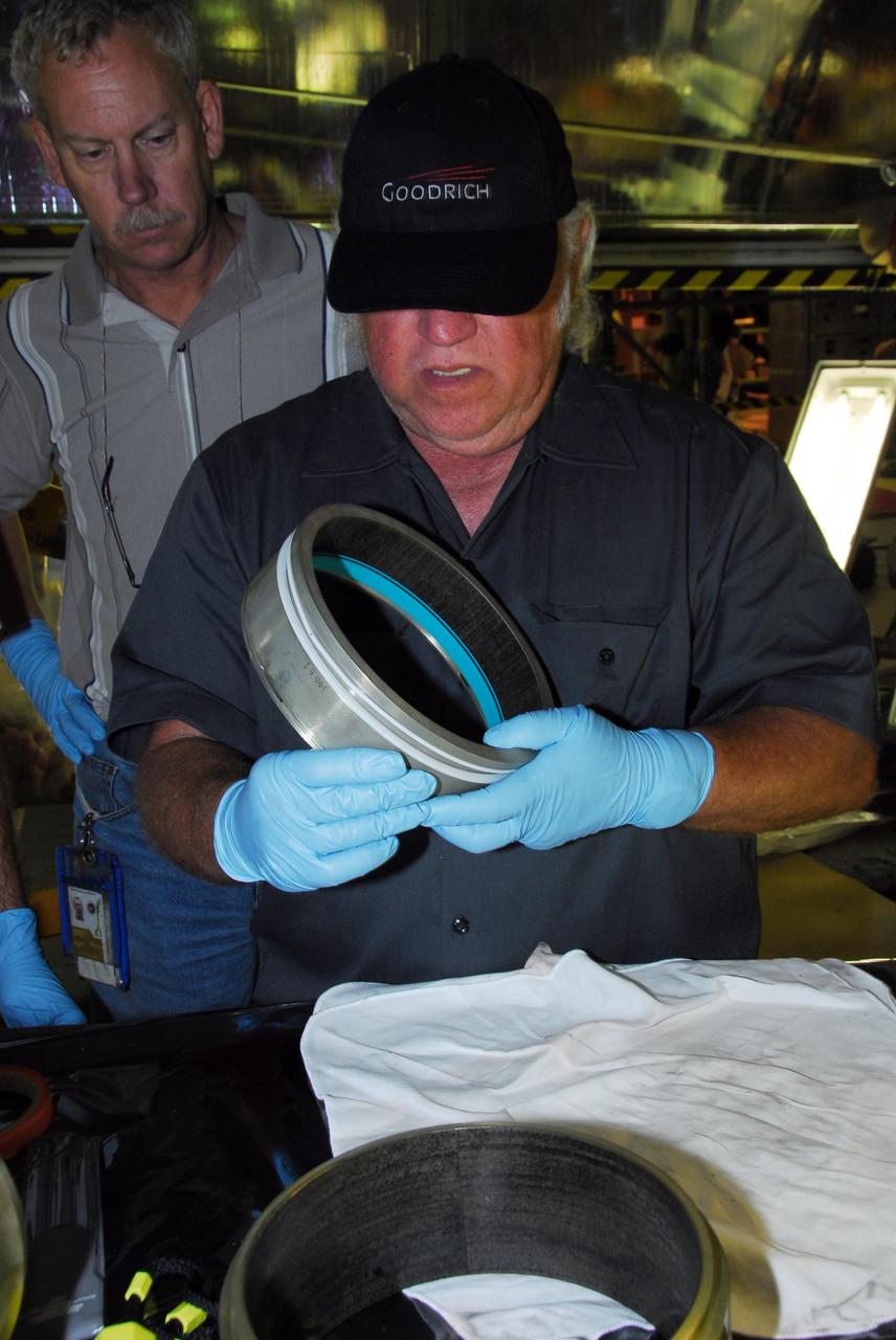
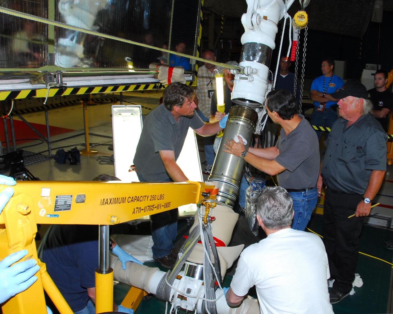
KENNEDY SPACE CENTER, FLA. - In the Orbiter Processing Facility, an actuator is set up on a table for a 3D digital scan. There are two actuators per engine on the Shuttle, one for pitch motion and one for yaw motion. The Space Shuttle Main Engine hydraulic servoactuators are used to gimbal the main engine.
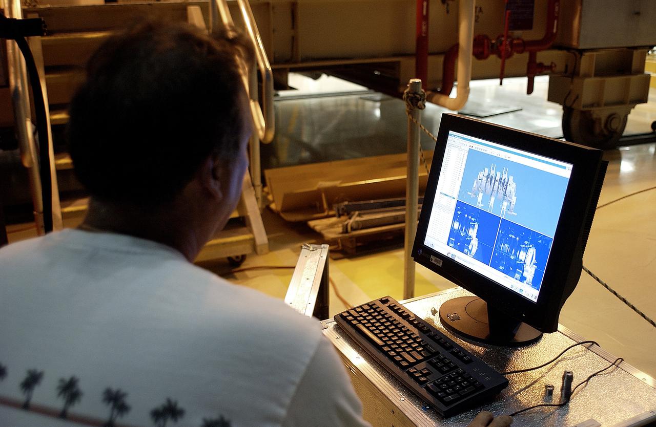
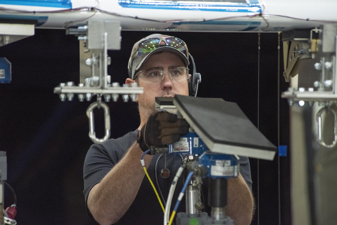
KENNEDY SPACE CENTER, FLA. - In the Orbiter Processing Facility, Boeing worker Alden Pitard looks at a 3D digital scan of an actuator. There are two actuators per engine on the Shuttle, one for pitch motion and one for yaw motion. The Space Shuttle Main Engine hydraulic servoactuators are used to gimbal the main engine.
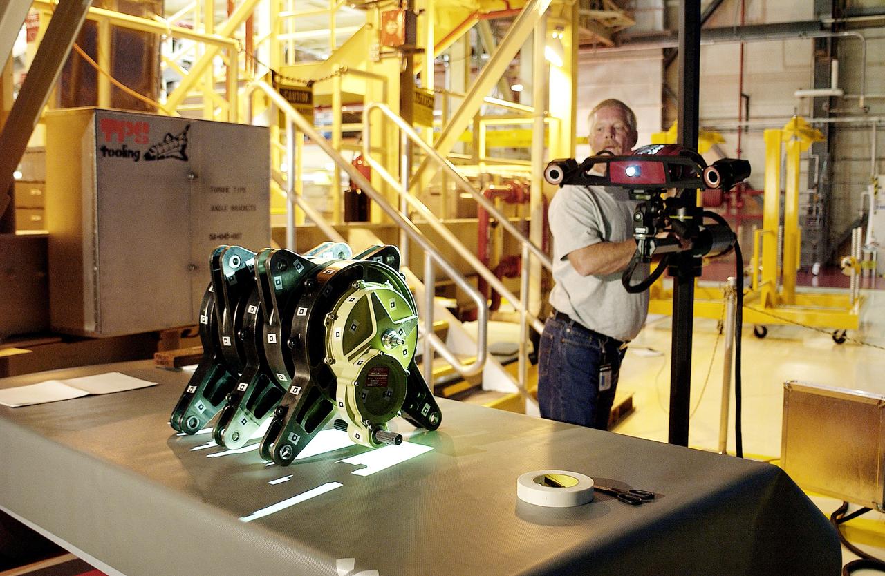
KENNEDY SPACE CENTER, FLA. - In the Orbiter Processing Facility, Dan Clark, with KSC Boeing, operates the camera for a 3D digital scan of the actuator on the table. There are two actuators per engine on the Shuttle, one for pitch motion and one for yaw motion. The Space Shuttle Main Engine hydraulic servoactuators are used to gimbal the main engine.
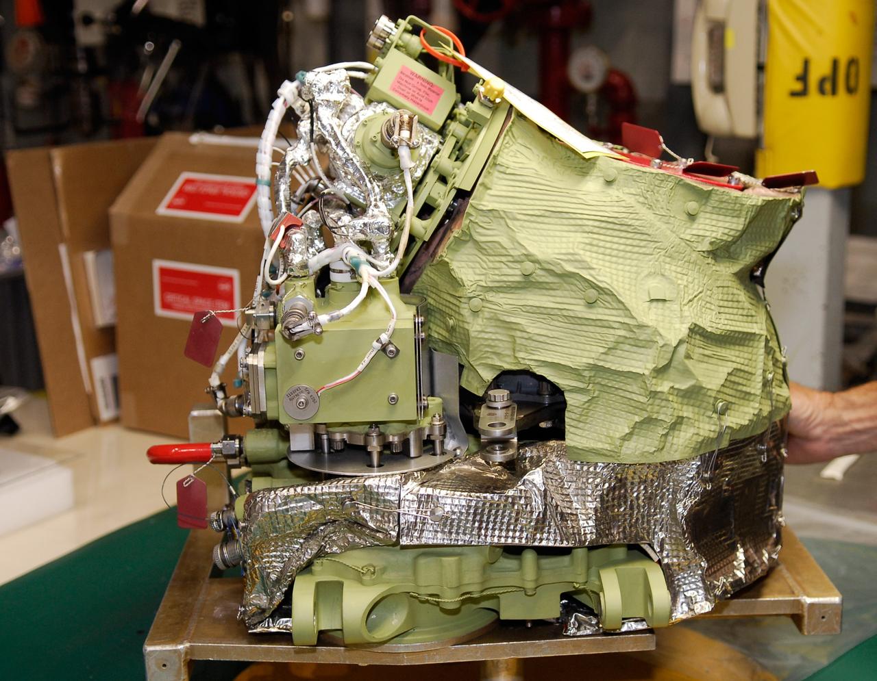
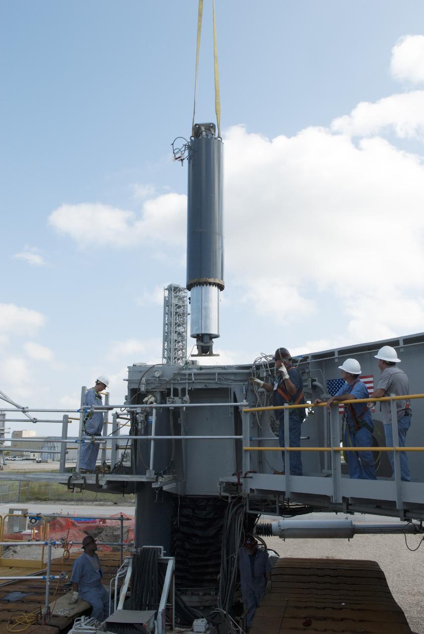
CAPE CANAVERAL, Fla. – Auxiliary power unit 3, or APU3, is ready for installation in space shuttle Endeavour for the STS-126 mission. The auxiliary power unit is a hydrazine-fueled, turbine-driven power unit that generates mechanical shaft power to drive a hydraulic pump that produces pressure for the orbiter's hydraulic system. There are three separate APUs, three hydraulic pumps and three hydraulic systems, located in the aft fuselage of the orbiter. When the three auxiliary power units are started five minutes before lift-off, the hydraulic systems are used to position the three main engines for activation, control various propellant valves on the engines and position orbiter aerosurfaces. The auxiliary power units are not operated after the first orbital maneuvering system thrusting period because hydraulic power is no longer required. One power unit is operated briefly one day before deorbit to support checkout of the orbiter flight control system. One auxiliary power unit is restarted before the deorbit thrusting period. The two remaining units are started after the deorbit thrusting maneuver and operate continuously through entry, landing and landing rollout. On STS-126, Endeavour will deliver a multi-purpose logistics module to the International Space Station. Launch is targeted for Nov. 10. Photo credit: NASA/Kim Shiflett
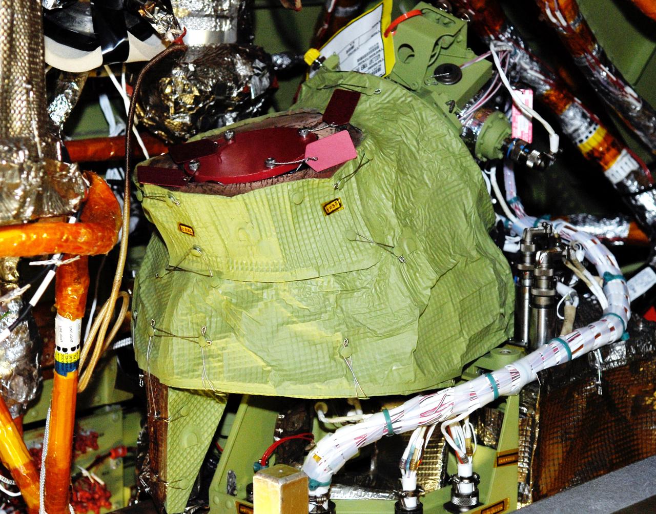
CAPE CANAVERAL, Fla. – In Orbiter Processing Facility bay No. 2, auxiliary power unit 3, or APU3, is in place on space shuttle Endeavour for the STS-126 mission. The auxiliary power unit is a hydrazine-fueled, turbine-driven power unit that generates mechanical shaft power to drive a hydraulic pump that produces pressure for the orbiter's hydraulic system. There are three separate APUs, three hydraulic pumps and three hydraulic systems, located in the aft fuselage of the orbiter. When the three auxiliary power units are started five minutes before lift-off, the hydraulic systems are used to position the three main engines for activation, control various propellant valves on the engines and position orbiter aerosurfaces. The auxiliary power units are not operated after the first orbital maneuvering system thrusting period because hydraulic power is no longer required. One power unit is operated briefly one day before deorbit to support checkout of the orbiter flight control system. One auxiliary power unit is restarted before the deorbit thrusting period. The two remaining units are started after the deorbit thrusting maneuver and operate continuously through entry, landing and landing rollout. On STS-126, Endeavour will deliver a multi-purpose logistics module to the International Space Station. Launch is targeted for Nov. 10. Photo credit: NASA/Kim Shiflett
CAPE CANAVERAL, Fla. – In Orbiter Processing Facility bay No. 2, technicians begin installation of an auxiliary power unit 3, or APU3, in space shuttle Endeavour for the STS-126 mission. The auxiliary power unit is a hydrazine-fueled, turbine-driven power unit that generates mechanical shaft power to drive a hydraulic pump that produces pressure for the orbiter's hydraulic system. There are three separate APUs, three hydraulic pumps and three hydraulic systems, located in the aft fuselage of the orbiter. When the three auxiliary power units are started five minutes before lift-off, the hydraulic systems are used to position the three main engines for activation, control various propellant valves on the engines and position orbiter aerosurfaces. The auxiliary power units are not operated after the first orbital maneuvering system thrusting period because hydraulic power is no longer required. One power unit is operated briefly one day before deorbit to support checkout of the orbiter flight control system. One auxiliary power unit is restarted before the deorbit thrusting period. The two remaining units are started after the deorbit thrusting maneuver and operate continuously through entry, landing and landing rollout. On STS-126, Endeavour will deliver a multi-purpose logistics module to the International Space Station. Launch is targeted for Nov. 10. Photo credit: NASA/Kim Shiflett
CAPE CANAVERAL, Fla. – In Orbiter Processing Facility bay No. 2, technicians install auxiliary power unit 3, or APU3, in space shuttle Endeavour for the STS-126 mission. The auxiliary power unit is a hydrazine-fueled, turbine-driven power unit that generates mechanical shaft power to drive a hydraulic pump that produces pressure for the orbiter's hydraulic system. There are three separate APUs, three hydraulic pumps and three hydraulic systems, located in the aft fuselage of the orbiter. When the three auxiliary power units are started five minutes before lift-off, the hydraulic systems are used to position the three main engines for activation, control various propellant valves on the engines and position orbiter aerosurfaces. The auxiliary power units are not operated after the first orbital maneuvering system thrusting period because hydraulic power is no longer required. One power unit is operated briefly one day before deorbit to support checkout of the orbiter flight control system. One auxiliary power unit is restarted before the deorbit thrusting period. The two remaining units are started after the deorbit thrusting maneuver and operate continuously through entry, landing and landing rollout. On STS-126, Endeavour will deliver a multi-purpose logistics module to the International Space Station. Launch is targeted for Nov. 10. Photo credit: NASA/Kim Shiflett
CAPE CANAVERAL, Fla. – In Orbiter Processing Facility bay No. 2, technicians begin installation of an auxiliary power unit 3, or APU3, in space shuttle Endeavour for the STS-126 mission. The auxiliary power unit is a hydrazine-fueled, turbine-driven power unit that generates mechanical shaft power to drive a hydraulic pump that produces pressure for the orbiter's hydraulic system. There are three separate APUs, three hydraulic pumps and three hydraulic systems, located in the aft fuselage of the orbiter. When the three auxiliary power units are started five minutes before lift-off, the hydraulic systems are used to position the three main engines for activation, control various propellant valves on the engines and position orbiter aerosurfaces. The auxiliary power units are not operated after the first orbital maneuvering system thrusting period because hydraulic power is no longer required. One power unit is operated briefly one day before deorbit to support checkout of the orbiter flight control system. One auxiliary power unit is restarted before the deorbit thrusting period. The two remaining units are started after the deorbit thrusting maneuver and operate continuously through entry, landing and landing rollout. On STS-126, Endeavour will deliver a multi-purpose logistics module to the International Space Station. Launch is targeted for Nov. 10. Photo credit: NASA/Kim Shiflett
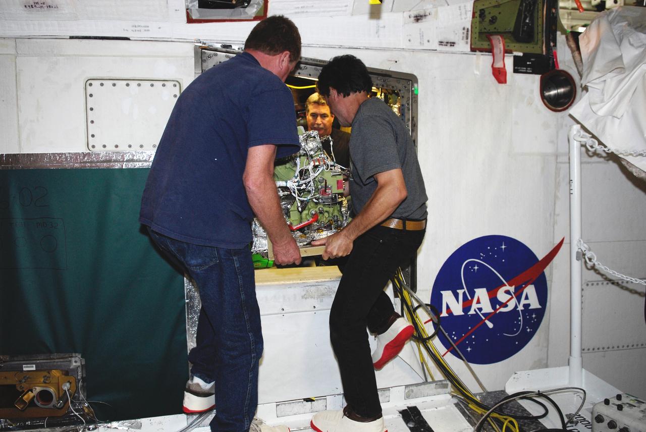
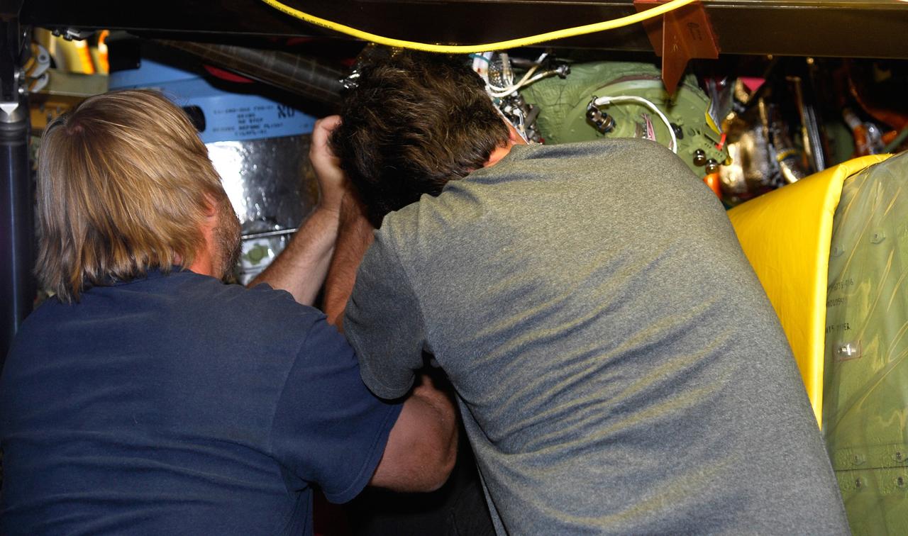
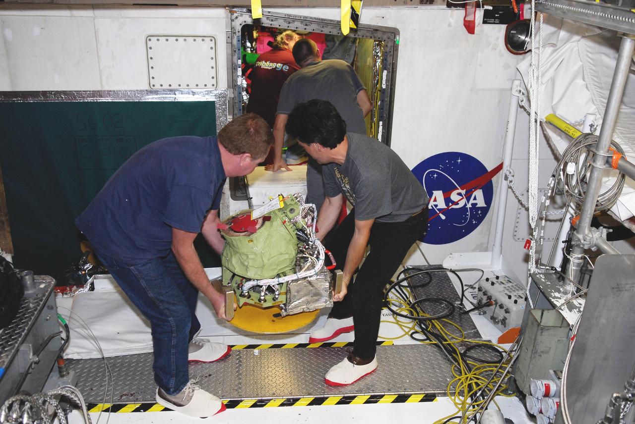
iss058e004176 (Jan. 16, 2019) --- Astronaut David Saint-Jacques of the Canadian Space Agency performs orbital plumbing work as he removes and replaces hydraulic components in the Waste and Hygiene Compartment, also known as the International Space Station's toilet located in the Tranquility module.
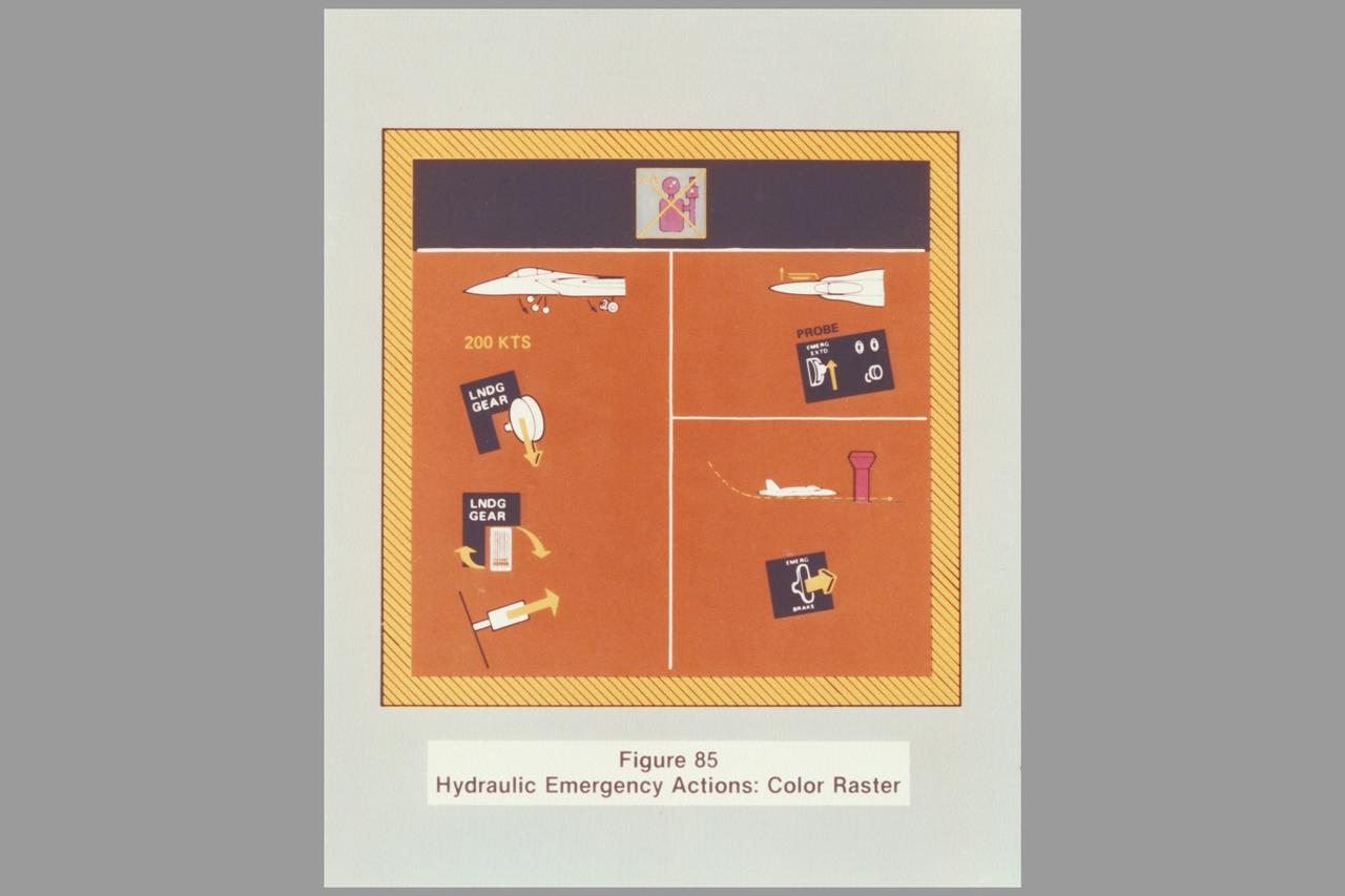
Date: Feb 1982 Photographer: Historical Air Force hydraulic emergency actions for generator failures (AFWAL TR-81-3156)

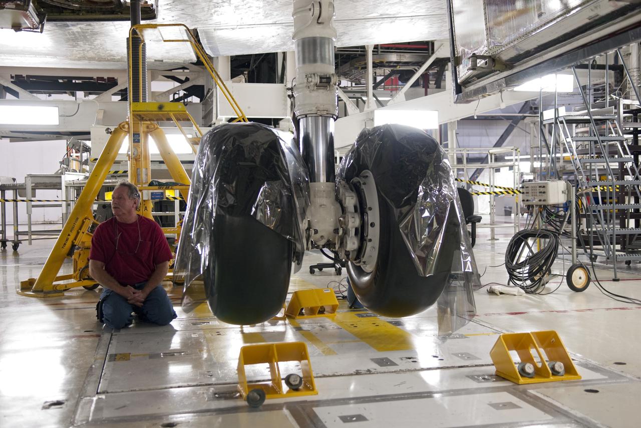
KENNEDY SPACE CENTER, FLA. -- In bay 3 of the Orbiter Processing Facility, a technician replaces a hydraulic seal in space shuttle Discovery's right main-gear strut. Engineers determined an observed leak of hydraulic fluid in the main landing gear strut exceeded specification and could not be reduced to an acceptable rate. Thus, the leaky seal and three other seals were replaced. Prior to discovery of the leak, the vehicle had been scheduled to roll over Sept. 19 from the OPF to the Vehicle Assembly Building. A new rollover date will be set for Discovery, which is targeted for launch on Oct. 23. Photo credit: NASA/George Shelton
KENNEDY SPACE CENTER, FLA. -- In bay 3 of the Orbiter Processing Facility, B.F. Goodrich technician David Cobb checks the hydraulic seal he replaced in space shuttle Discovery's right main-gear strut. Engineers determined an observed leak of hydraulic fluid in the main landing gear strut exceeded specification and could not be reduced to an acceptable rate. Thus, the leaky seal and three other seals were replaced. Prior to discovery of the leak, the vehicle had been scheduled to roll over Sept. 19 from the OPF to the Vehicle Assembly Building. A new rollover date will be set for Discovery, which is targeted for launch on Oct. 23. Photo credit: NASA/George Shelton

KENNEDY SPACE CENTER, FLA. -- With space shuttle Discovery's right main landing gear reassembled following the replacement of its four hydraulic seals, technicians now are carrying out a series of tests on the system. The shuttle is in the Orbiter Processing Facility, or OPF. One of Discovery’s struts, which act as shock absorbers during the shuttle's landing, began leaking hydraulic fluid last week. Prior to discovery of the leak, the vehicle had been scheduled to roll over Sept. 19 from the OPF to the Vehicle Assembly Building. The rollover date will be determined after the tests. Discovery is targeted for launch on Oct. 23. Photo credit: NASA/Jack Pfaller
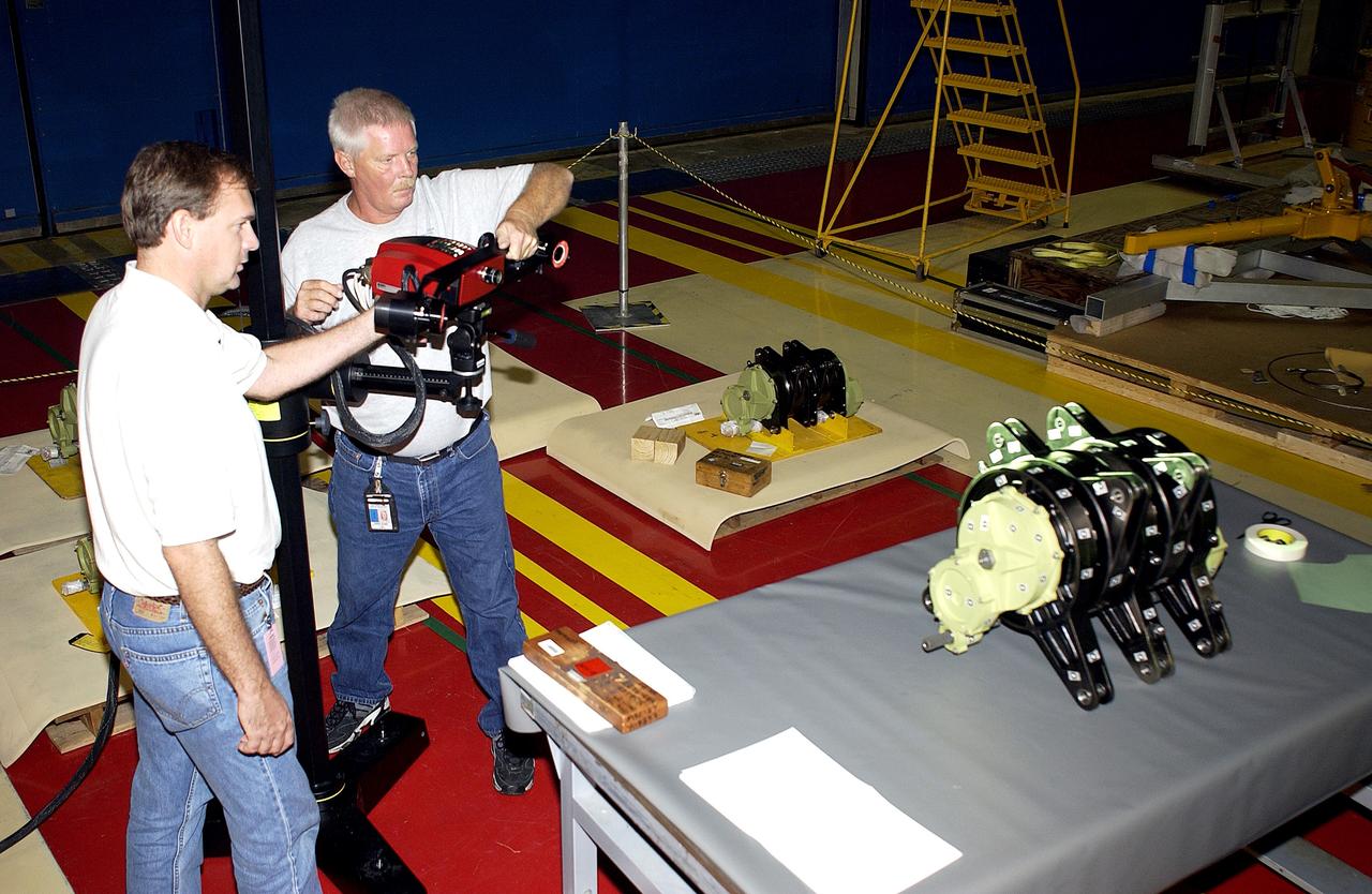
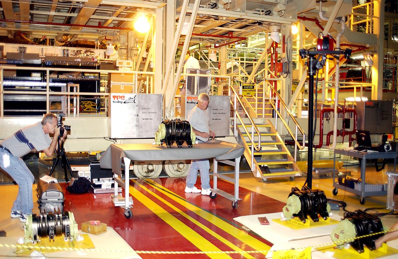
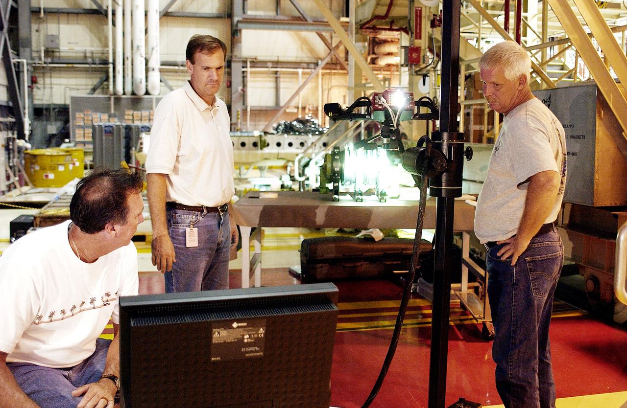
KENNEDY SPACE CENTER, FLA. - Boeing workers get ready to perform a 3D digital scan of the actuator on the table. At left is John Macke, from Boeing, St. Louis. At right is Dan Clark.. There are two actuators per engine on the Shuttle, one for pitch motion and one for yaw motion. The Space Shuttle Main Engine hydraulic servoactuators are used to gimbal the main engine.
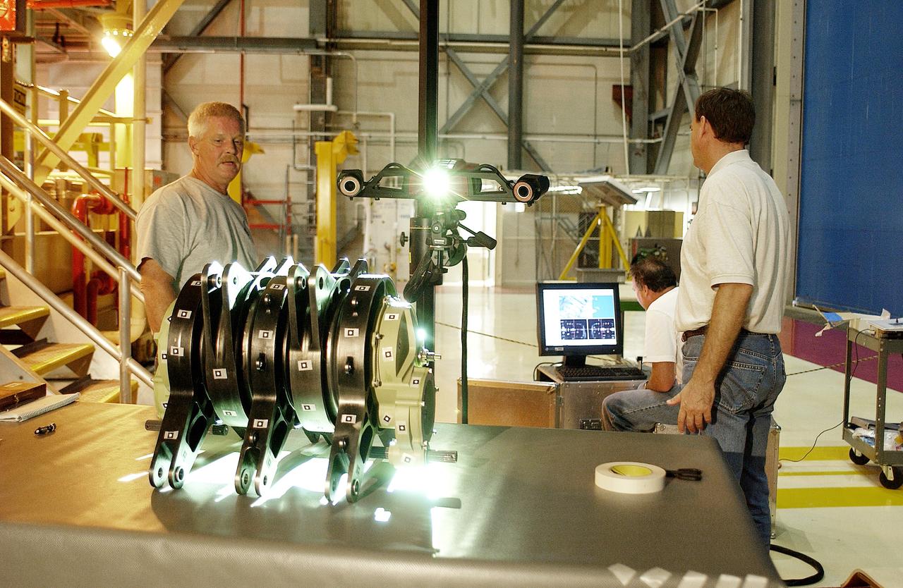
KENNEDY SPACE CENTER, FLA. - Boeing workers perform a 3D digital scan of the actuator on the table. At left is Dan Clark. At right are Alden Pitard (seated at computer) and John Macke, from Boeing, St. Louis. . There are two actuators per engine on the Shuttle, one for pitch motion and one for yaw motion. The Space Shuttle Main Engine hydraulic servoactuators are used to gimbal the main engine.
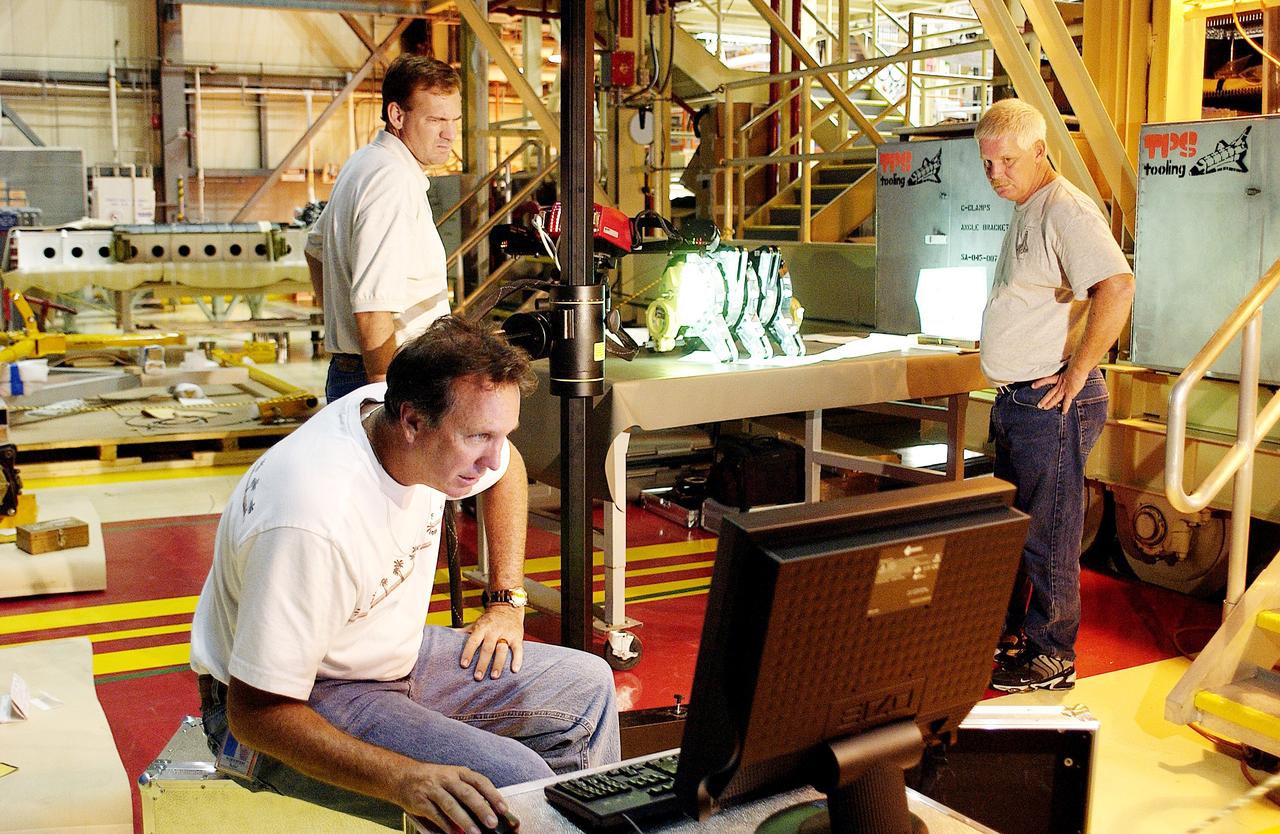
KENNEDY SPACE CENTER, FLA. - John Macke (standing, left), with Boeing St. Louis, Alden Pitard (seated, left) and Dan Clark (right), with KSC Boeing, look at a monitor after 3D digital scanning of actuators in the Orbiter Processing Facility. There are two actuators per engine on the Shuttle, one for pitch motion and one for yaw motion. The Space Shuttle Main Engine hydraulic servoactuators are used to gimbal the main engine.
KENNEDY SPACE CENTER, FLA. - John Macke (standing, center), with Boeing St. Louis, Alden Pitard (seated, left) and Dan Clark (right), with KSC Boeing, check results after 3D digital scanning of actuators in the Orbiter Processing Facility. There are two actuators per engine on the Shuttle, one for pitch motion and one for yaw motion. The Space Shuttle Main Engine hydraulic servoactuators are used to gimbal the main engine.
Ray Sadler adjusts hydraulic actuators with pads to the wing of the X-57 distributed electric aircraft wing at NASA's Armstrong Flight Research Center in California. Tests increased confidence in the wing's durability and calibrated installed strain gauges for inflight load monitoring of the wing.

Here is an image of the X-59’s 13-foot General Electric F414 engine as the team prepares for a fit check. Making sure components, like the aircraft’s hydraulic lines, which help control functions like brakes or landing gear, and wiring of the engine, fit properly is essential to the aircraft’s safety. Once complete, the X-59 aircraft will demonstrate the ability to fly supersonic while reducing the loud sonic boom to a quiet sonic thump and help enable commercial supersonic air travel over land.
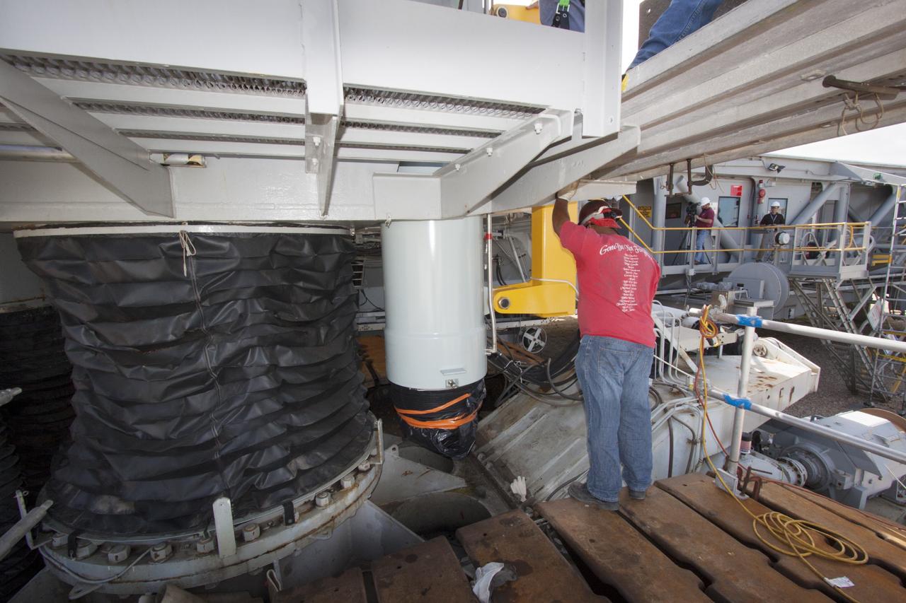
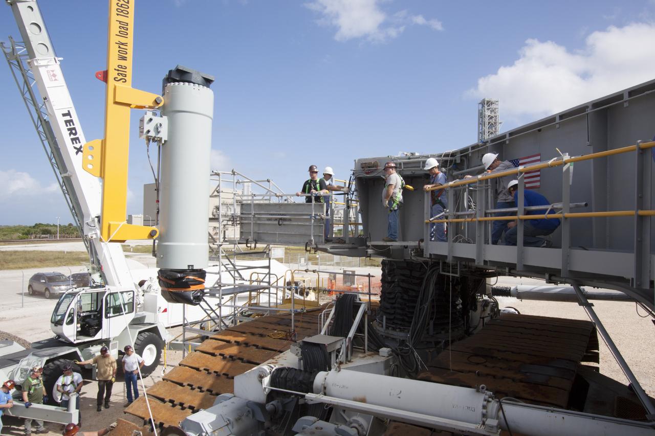
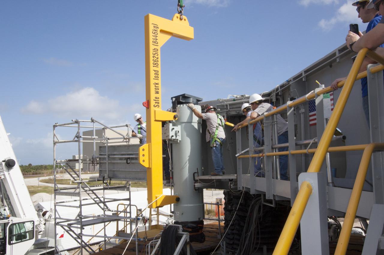
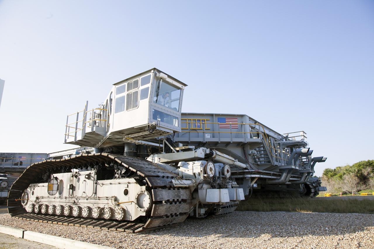
CAPE CANAVERAL, Fla. – Ground support equipment technicians monitor the progress as one of the jacking, equalizing and leveling, or JEL, hydraulic cylinders is lifted from crawler-transporter 1 at the crawler transporter maintenance facility at NASA’s Kennedy Space Center in Florida. Sixteen new JEL hydraulic cylinders will be installed on CT-1 to increase load carrying capacity and reliability. The Ground Systems Development and Operations Program at Kennedy continues to upgrade CT-1 as part of its general maintenance. CT-1 could be available to carry commercial launch vehicles to the launch pad. The crawler-transporters were used to carry the mobile launcher platform and space shuttle to Launch Complex 39 for space shuttle launches for 30 years. Photo credit: NASA/Tim Jacobs
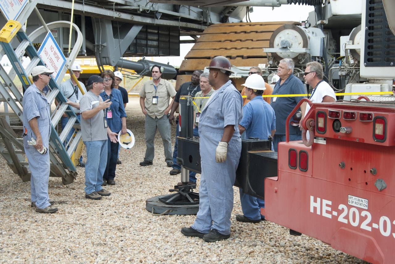
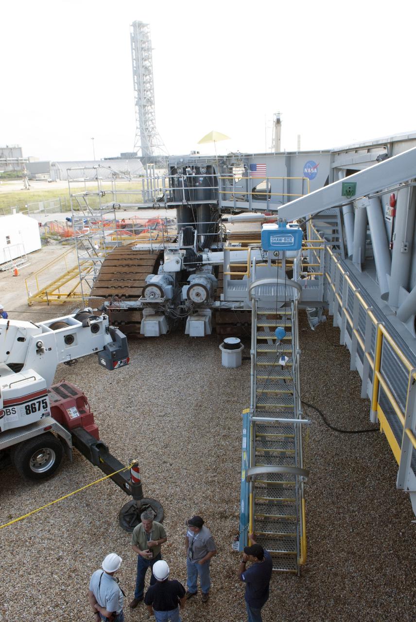
CAPE CANAVERAL, Fla. – Ground support equipment technicians review procedures before removing jacking, equalizing and leveling, or JEL, hydraulic cylinders from crawler-transporter 1 at the crawler transporter maintenance facility at NASA’s Kennedy Space Center in Florida. Sixteen new JEL hydraulic cylinders will be installed on CT-1 to increase load carrying capacity and reliability. The Ground Systems Development and Operations Program at Kennedy continues to upgrade CT-1 as part of its general maintenance. CT-1 could be available to carry commercial launch vehicles to the launch pad. The crawler-transporters were used to carry the mobile launcher platform and space shuttle to Launch Complex 39 for space shuttle launches for 30 years. Photo credit: NASA/Tim Jacobs
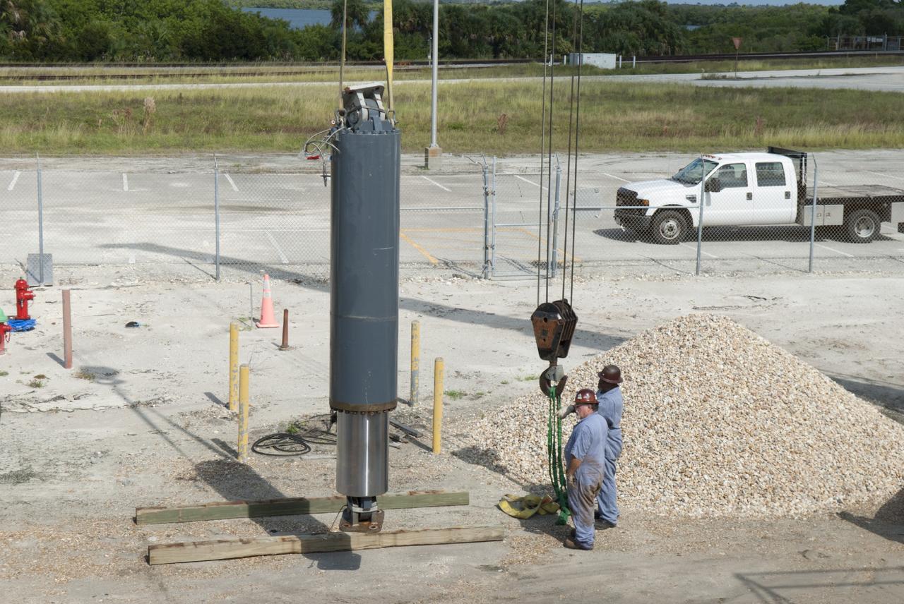
CAPE CANAVERAL, Fla. – Preparations are underway to begin removing the jacking, equalizing and leveling, or JEL, hydraulic cylinders from crawler-transporter 1 at the crawler transporter maintenance facility at NASA’s Kennedy Space Center in Florida. Sixteen new JEL hydraulic cylinders will be installed on CT-1 to increase load carrying capacity and reliability. The Ground Systems Development and Operations Program at Kennedy continues to upgrade CT-1 as part of its general maintenance. CT-1 could be available to carry commercial launch vehicles to the launch pad. The crawler-transporters were used to carry the mobile launcher platform and space shuttle to Launch Complex 39 for space shuttle launches for 30 years. Photo credit: NASA/Tim Jacobs
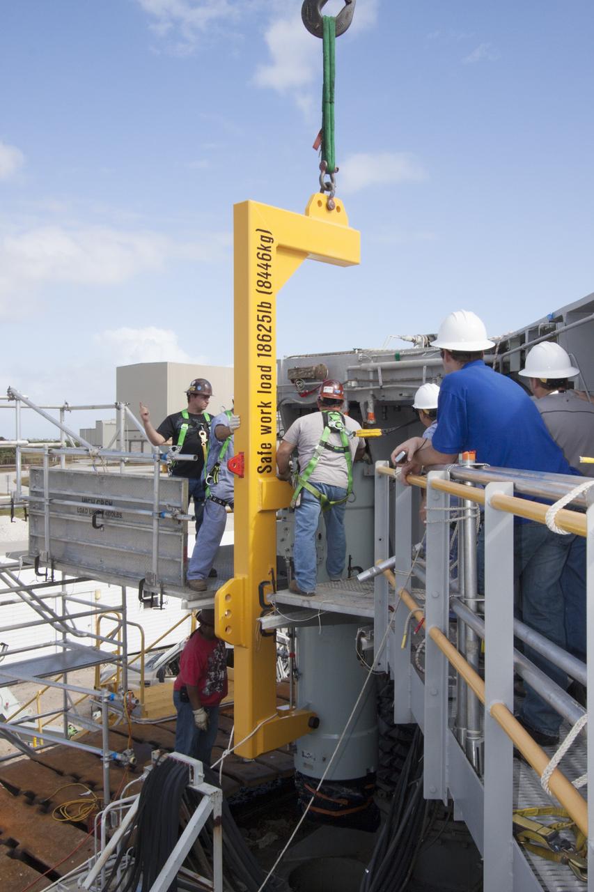
CAPE CANAVERAL, Fla. – Ground support equipment technicians assist as a crane moves a new jacking, equalizing and leveling, or JEL, hydraulic cylinder close for installation on crawler-transporter 1 at the crawler transporter maintenance facility at NASA’s Kennedy Space Center in Florida. New JEL hydraulic cylinders will be installed on CT-1 to test them for increased load carrying capacity and reliability. The Ground Systems Development and Operations Program at Kennedy continues to upgrade CT-1 as part of its general maintenance. CT-1 could be available to carry a variety of launch vehicles to the launch pad. Two crawler-transporters were used to carry the mobile launcher platform and space shuttle to Launch Complex 39 for space shuttle launches for 30 years. Photo credit: NASA/Jim Grossmann
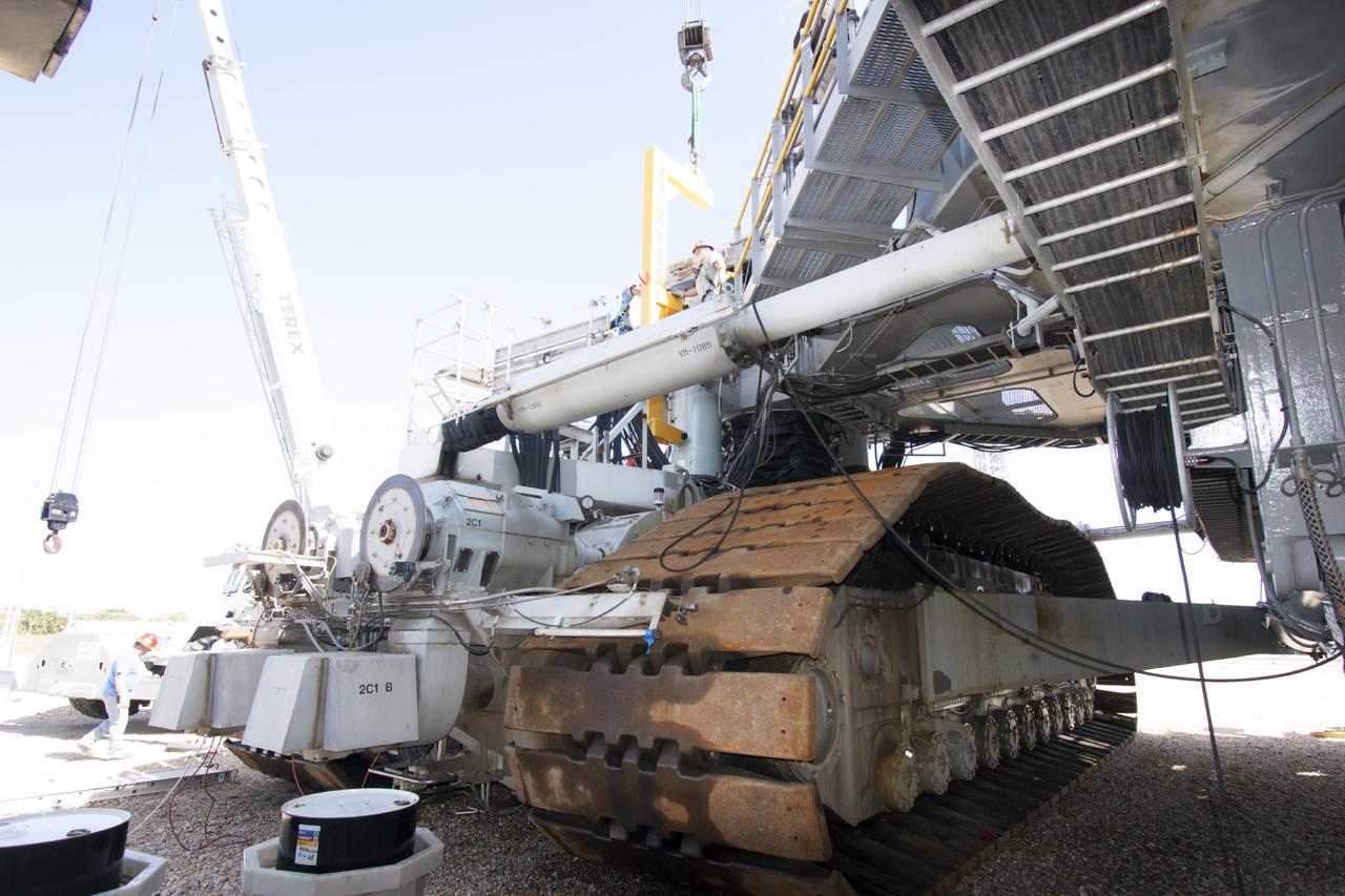
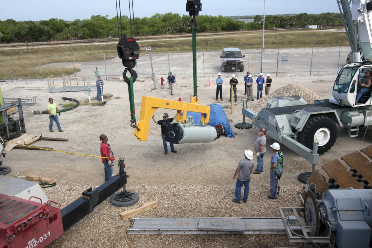
CAPE CANAVERAL, Fla. – One of the jacking, equalizing and leveling, or JEL, hydraulic cylinders is lifted away from crawler-transporter 1 at the crawler transporter maintenance facility at NASA’s Kennedy Space Center in Florida. Sixteen new JEL hydraulic cylinders will be installed on CT-1 to increase load carrying capacity and reliability. The Ground Systems Development and Operations Program at Kennedy continues to upgrade CT-1 as part of its general maintenance. CT-1 could be available to carry commercial launch vehicles to the launch pad. The crawler-transporters were used to carry the mobile launcher platform and space shuttle to Launch Complex 39 for space shuttle launches for 30 years. Photo credit: NASA/Tim Jacobs
CAPE CANAVERAL, Fla. – Ground support equipment technicians monitor the progress as one of the jacking, equalizing and leveling, or JEL, hydraulic cylinders is lowered to the ground after it was removed from crawler-transporter 1. The work is being performed at the crawler transporter maintenance facility at NASA’s Kennedy Space Center in Florida. Sixteen new JEL hydraulic cylinders will be installed on CT-1 to increase load carrying capacity and reliability. The Ground Systems Development and Operations Program at Kennedy continues to upgrade CT-1 as part of its general maintenance. CT-1 could be available to carry commercial launch vehicles to the launch pad. The crawler-transporters were used to carry the mobile launcher platform and space shuttle to Launch Complex 39 for space shuttle launches for 30 years. Photo credit: NASA/Tim Jacobs
CAPE CANAVERAL, Fla. – Preparations are underway to begin removing the jacking, equalizing and leveling, or JEL, hydraulic cylinders from crawler-transporter 1 at the crawler transporter maintenance facility at NASA’s Kennedy Space Center in Florida. Sixteen new JEL hydraulic cylinders will be installed on CT-1 to increase load carrying capacity and reliability. The Ground Systems Development and Operations Program at Kennedy continues to upgrade CT-1 as part of its general maintenance. CT-1 could be available to carry commercial launch vehicles to the launch pad. The crawler-transporters were used to carry the mobile launcher platform and space shuttle to Launch Complex 39 for space shuttle launches for 30 years. Photo credit: NASA/Tim Jacobs
CAPE CANAVERAL, Fla. – Ground support equipment technicians assist as a crane is used to move a new jacking, equalizing and leveling, or JEL, hydraulic cylinder closer for installation on crawler-transporter 1 at the crawler transporter maintenance facility at NASA’s Kennedy Space Center in Florida. New JEL hydraulic cylinders will be installed on CT-1 to test them for increased load carrying capacity and reliability. The Ground Systems Development and Operations Program at Kennedy continues to upgrade CT-1 as part of its general maintenance. CT-1 could be available to carry a variety of launch vehicles to the launch pad. Two crawler-transporters were used to carry the mobile launcher platform and space shuttle to Launch Complex 39 for space shuttle launches for 30 years. Photo credit: NASA/Jim Grossmann
A ground support technician checks the new hydraulic cylinders on crawler-transporter 2 (CT-2) as the vehicle moves slowly along the crawlerway toward the Vehicle Assembly Building at NASA's Kennedy Space Center in Florida. The crawler took a trip to the Pad A/B split to test upgrades recently completed that will allow the giant vehicle to handle the load of the agency's Space Launch System rocket and Orion spacecraft atop the mobile launcher. The Ground Systems Development and Operations Program oversaw upgrades to the 50-year-old CT-2. New generators, gear assemblies, jacking, equalizing and leveling (JEL) hydraulic cylinders, roller bearings and brakes were installed, and other components were upgraded to prepare for Exploration Mission 1.
CAPE CANAVERAL, Fla. – Ground support equipment technicians prepare to remove the jacking, equalizing and leveling, or JEL, hydraulic cylinders from crawler-transporter 1 at the crawler transporter maintenance facility at NASA’s Kennedy Space Center in Florida. Sixteen new JEL hydraulic cylinders will be installed on CT-1 to increase load carrying capacity and reliability. The Ground Systems Development and Operations Program at Kennedy continues to upgrade CT-1 as part of its general maintenance. CT-1 could be available to carry commercial launch vehicles to the launch pad. The crawler-transporters were used to carry the mobile launcher platform and space shuttle to Launch Complex 39 for space shuttle launches for 30 years. Photo credit: NASA/Tim Jacobs
KENNEDY SPACE CENTER, FLA. -- This photo shows the leaking hydraulic seal in space shuttle Discovery's right main-gear strut. United Space Alliance and B.F. Goodrich technicians are working to replace the seal. The struts act as shock absorbers during the shuttle's landing. Engineers determined the observed leak of hydraulic fluid in the main landing gear strut exceeded specification and could not be reduced to an acceptable rate. Removing the strut and replacing seals require disconnecting and replacing the brakes and tires, disconnecting and reconnecting instruments and other requirements to allow access to the strut. Discovery had been scheduled to roll over Sept. 19 from its processing hangar to the Vehicle Assembly Building. A new rollover date will be set after technicians determine how long replacing the seal will take. Photo credit: NASA/George Shelton
CAPE CANAVERAL, Fla. – Ground support equipment technicians monitor the progress as a forklift is used to carry a new jacking, equalizing and leveling, or JEL, hydraulic cylinder for installation on crawler-transporter 1 at the crawler transporter maintenance facility at NASA’s Kennedy Space Center in Florida. New JEL hydraulic cylinders will be installed on CT-1 to test them for increased load carrying capacity and reliability. The Ground Systems Development and Operations Program at Kennedy continues to upgrade CT-1 as part of its general maintenance. CT-1 could be available to carry a variety of launch vehicles to the launch pad. Two crawler-transporters were used to carry the mobile launcher platform and space shuttle to Launch Complex 39 for space shuttle launches for 30 years. Photo credit: NASA/Jim Grossmann
CAPE CANAVERAL, Fla. – Preparations are underway to begin removing the jacking, equalizing and leveling, or JEL, hydraulic cylinders from crawler-transporter 1 at the crawler transporter maintenance facility at NASA’s Kennedy Space Center in Florida. Sixteen new JEL hydraulic cylinders will be installed on CT-1 to increase load carrying capacity and reliability. The Ground Systems Development and Operations Program at Kennedy continues to upgrade CT-1 as part of its general maintenance. CT-1 could be available to carry commercial launch vehicles to the launch pad. The crawler-transporters were used to carry the mobile launcher platform and space shuttle to Launch Complex 39 for space shuttle launches for 30 years. Photo credit: NASA/Tim Jacobs

CAPE CANAVERAL, Fla. – A forklift is used to carry a new jacking, equalizing and leveling, or JEL, hydraulic cylinder for installation on crawler-transporter 1 at the crawler transporter maintenance facility at NASA’s Kennedy Space Center in Florida. New JEL hydraulic cylinders will be installed on CT-1 to test them for increased load carrying capacity and reliability. The Ground Systems Development and Operations Program at Kennedy continues to upgrade CT-1 as part of its general maintenance. CT-1 could be available to carry a variety of launch vehicles to the launch pad. Two crawler-transporters were used to carry the mobile launcher platform and space shuttle to Launch Complex 39 for space shuttle launches for 30 years. Photo credit: NASA/Jim Grossmann
CAPE CANAVERAL, Fla. – Ground support equipment technicians assist as a crane moves a new jacking, equalizing and leveling, or JEL, hydraulic cylinder close for installation on crawler-transporter 1 at the crawler transporter maintenance facility at NASA’s Kennedy Space Center in Florida. New JEL hydraulic cylinders will be installed on CT-1 to test them for increased load carrying capacity and reliability. The Ground Systems Development and Operations Program at Kennedy continues to upgrade CT-1 as part of its general maintenance. CT-1 could be available to carry a variety of launch vehicles to the launch pad. Two crawler-transporters were used to carry the mobile launcher platform and space shuttle to Launch Complex 39 for space shuttle launches for 30 years. Photo credit: NASA/Jim Grossmann
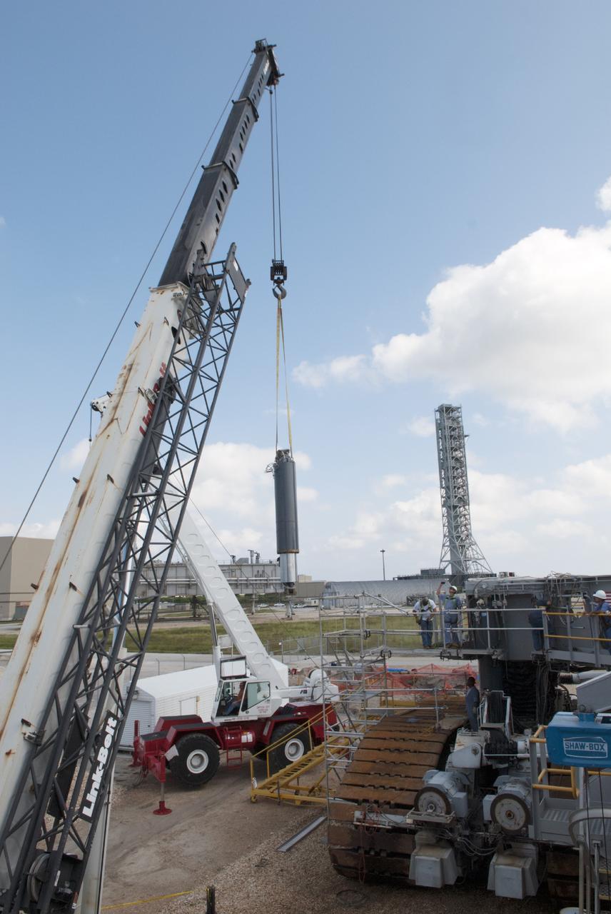
CAPE CANAVERAL, Fla. – Ground support equipment technicians monitor the progress as a crane is used to lift and move a new jacking, equalizing and leveling, or JEL, hydraulic cylinder for installation on crawler-transporter 1 at the crawler transporter maintenance facility at NASA’s Kennedy Space Center in Florida. New JEL hydraulic cylinders will be installed on CT-1 to test them for increased load carrying capacity and reliability. The Ground Systems Development and Operations Program at Kennedy continues to upgrade CT-1 as part of its general maintenance. CT-1 could be available to carry a variety of launch vehicles to the launch pad. Two crawler-transporters were used to carry the mobile launcher platform and space shuttle to Launch Complex 39 for space shuttle launches for 30 years. Photo credit: NASA/Jim Grossmann
KENNEDY SPACE CENTER, FLA. --In bay 3 of the Orbiter Processing Facility, United Space Alliance technicians reassemble space shuttle Discovery's right main-gear strut back together. The components were removed in order to replace a hydraulic seal inside. Engineers determined an observed leak of hydraulic fluid in the main landing gear strut exceeded specification and could not be reduced to an acceptable rate. Thus, the leaky seal and three other seals were replaced. Prior to discovery of the leak, the vehicle had been scheduled to roll over Sept. 19 from the OPF to the Vehicle Assembly Building. A new rollover date will be set for Discovery, which is targeted for launch on Oct. 23. Photo credit: NASA/George Shelton
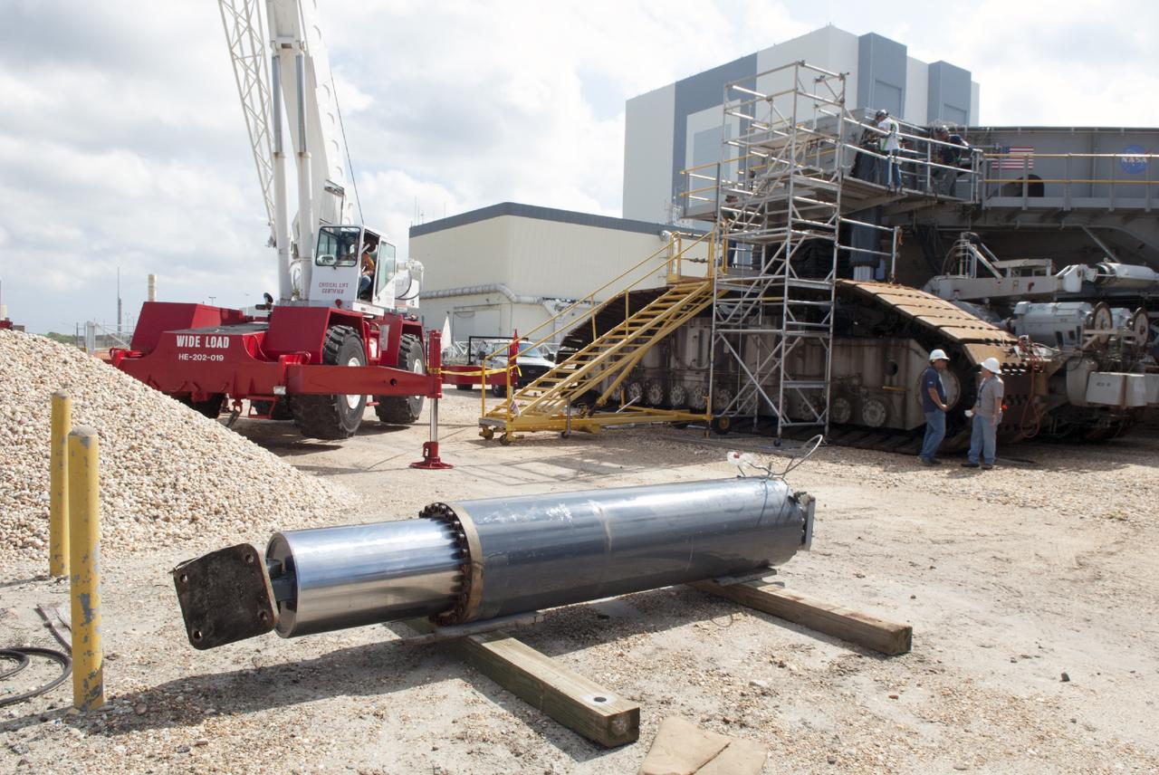
CAPE CANAVERAL, Fla. – One of the jacking, equalizing and leveling, or JEL, hydraulic cylinders has been removed from crawler-transporter 1 at the crawler transporter maintenance facility at NASA’s Kennedy Space Center in Florida. Sixteen new JEL hydraulic cylinders will be installed on CT-1 to increase load carrying capacity and reliability. The Ground Systems Development and Operations Program at Kennedy continues to upgrade CT-1 as part of its general maintenance. CT-1 could be available to carry commercial launch vehicles to the launch pad. The crawler-transporters were used to carry the mobile launcher platform and space shuttle to Launch Complex 39 for space shuttle launches for 30 years. Photo credit: NASA/Tim Jacobs
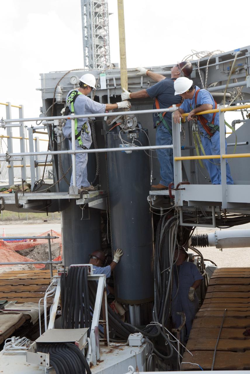
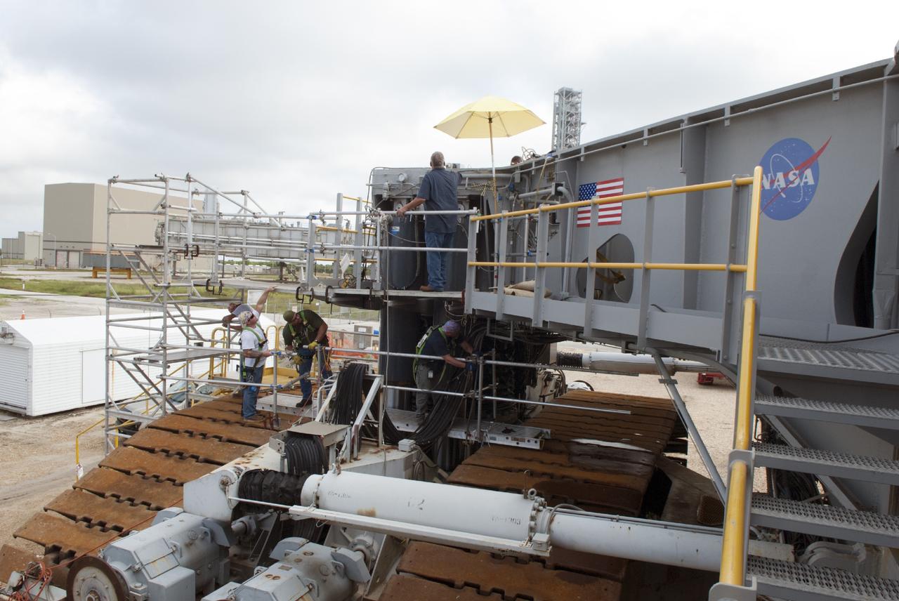
CAPE CANAVERAL, Fla. – Ground support equipment technicians prepare one of the jacking, equalizing and leveling, or JEL, hydraulic cylinders for removal from crawler-transporter 1 at the crawler transporter maintenance facility at NASA’s Kennedy Space Center in Florida. Sixteen new JEL hydraulic cylinders will be installed on CT-1 to increase load carrying capacity and reliability. The Ground Systems Development and Operations Program at Kennedy continues to upgrade CT-1 as part of its general maintenance. CT-1 could be available to carry commercial launch vehicles to the launch pad. The crawler-transporters were used to carry the mobile launcher platform and space shuttle to Launch Complex 39 for space shuttle launches for 30 years. Photo credit: NASA/Tim Jacobs
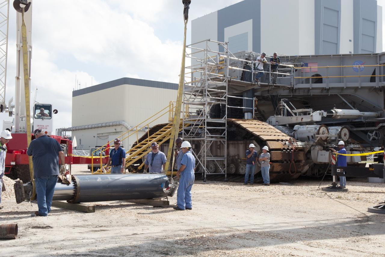
CAPE CANAVERAL, Fla. – Ground support equipment technicians assist as one of the jacking, equalizing and leveling, or JEL, hydraulic cylinders is lowered to the ground after it was removed from crawler-transporter 1. The work is being performed at the crawler transporter maintenance facility at NASA’s Kennedy Space Center in Florida. Sixteen new JEL hydraulic cylinders will be installed on CT-1 to increase load carrying capacity and reliability. The Ground Systems Development and Operations Program at Kennedy continues to upgrade CT-1 as part of its general maintenance. CT-1 could be available to carry commercial launch vehicles to the launch pad. The crawler-transporters were used to carry the mobile launcher platform and space shuttle to Launch Complex 39 for space shuttle launches for 30 years. Photo credit: NASA/Tim Jacobs
KENNEDY SPACE CENTER, FLA. -- In bay 3 of the Orbiter Processing Facility, United Space Alliance technicians make final adjustments on space shuttle Discovery's starboard landing gear. The components were removed in order to replace a hydraulic seal in the right main-gear strut. Engineers determined an observed leak of hydraulic fluid in the main landing gear strut exceeded specification and could not be reduced to an acceptable rate. Thus, the leaky seal and three other seals were replaced. Prior to discovery of the leak, the vehicle had been scheduled to roll over Sept. 19 from the OPF to the Vehicle Assembly Building. A new rollover date will be set for Discovery, which is targeted for launch on Oct. 23. Photo credit: NASA/George Shelton
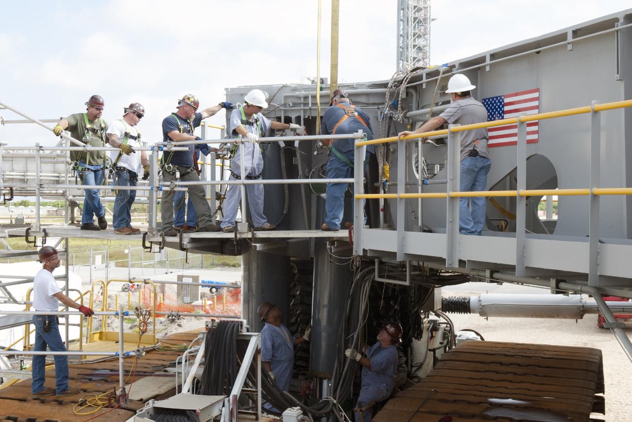
CAPE CANAVERAL, Fla. – Ground support equipment technicians prepare one of the jacking, equalizing and leveling, or JEL, hydraulic cylinders for removal from crawler-transporter 1 at the crawler transporter maintenance facility at NASA’s Kennedy Space Center in Florida. Sixteen new JEL hydraulic cylinders will be installed on CT-1 to increase load carrying capacity and reliability. The Ground Systems Development and Operations Program at Kennedy continues to upgrade CT-1 as part of its general maintenance. CT-1 could be available to carry commercial launch vehicles to the launch pad. The crawler-transporters were used to carry the mobile launcher platform and space shuttle to Launch Complex 39 for space shuttle launches for 30 years. Photo credit: NASA/Tim Jacobs
CAPE CANAVERAL, Fla. – Ground support equipment technicians assist as a crane is used to move a new jacking, equalizing and leveling, or JEL, hydraulic cylinder closer for installation on crawler-transporter 1 at the crawler transporter maintenance facility at NASA’s Kennedy Space Center in Florida. New JEL hydraulic cylinders will be installed on CT-1 to test them for increased load carrying capacity and reliability. The Ground Systems Development and Operations Program at Kennedy continues to upgrade CT-1 as part of its general maintenance. CT-1 could be available to carry a variety of launch vehicles to the launch pad. Two crawler-transporters were used to carry the mobile launcher platform and space shuttle to Launch Complex 39 for space shuttle launches for 30 years. Photo credit: NASA/Jim Grossmann
CAPE CANAVERAL, Fla. – Ground support equipment technicians monitor the progress as a crane is used to lift a new jacking, equalizing and leveling, or JEL, hydraulic cylinder for installation on crawler-transporter 1 at the crawler transporter maintenance facility at NASA’s Kennedy Space Center in Florida. New JEL hydraulic cylinders will be installed on CT-1 to test them for increased load carrying capacity and reliability. The Ground Systems Development and Operations Program at Kennedy continues to upgrade CT-1 as part of its general maintenance. CT-1 could be available to carry a variety of launch vehicles to the launch pad. Two crawler-transporters were used to carry the mobile launcher platform and space shuttle to Launch Complex 39 for space shuttle launches for 30 years. Photo credit: NASA/Jim Grossmann
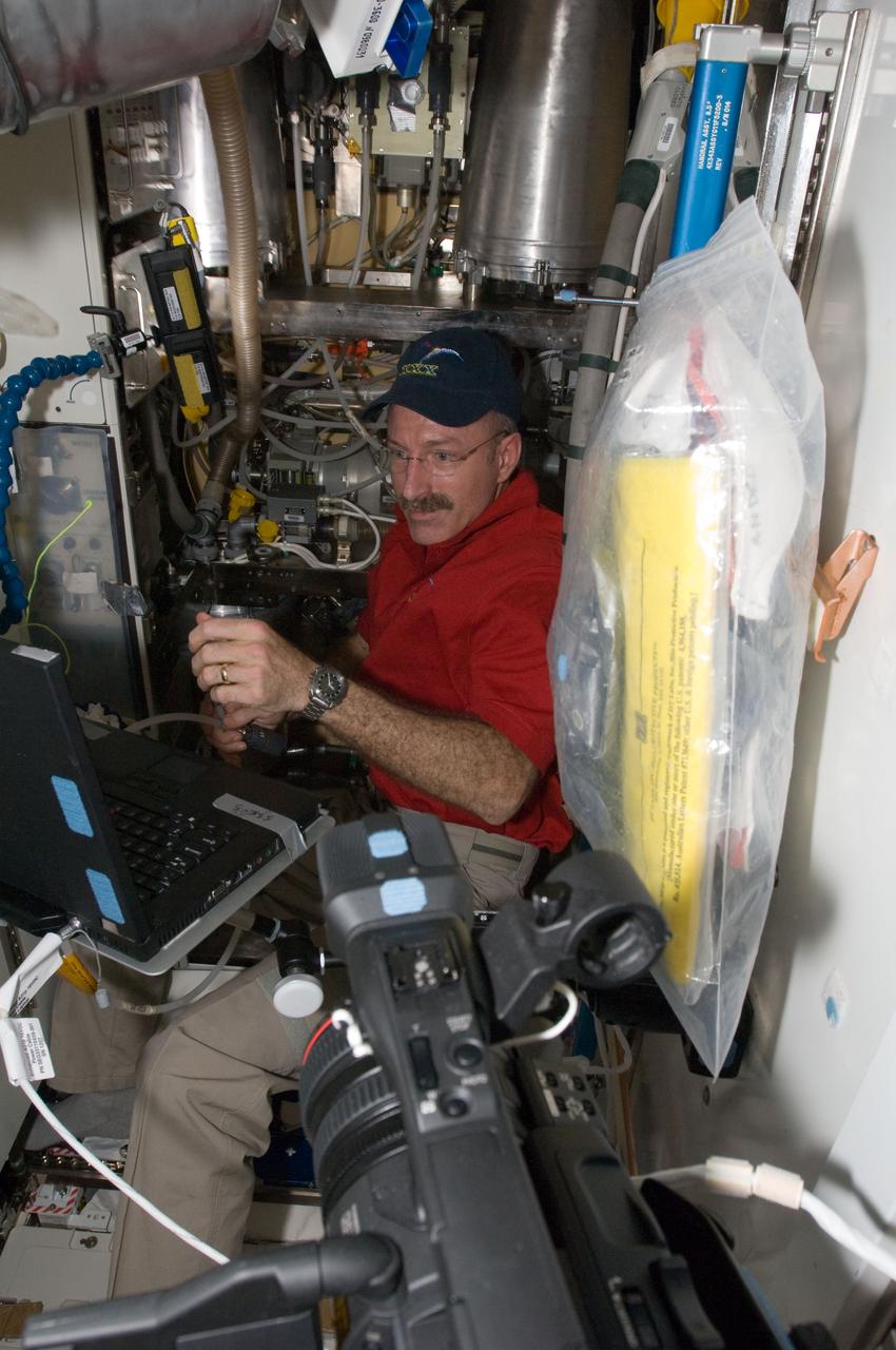
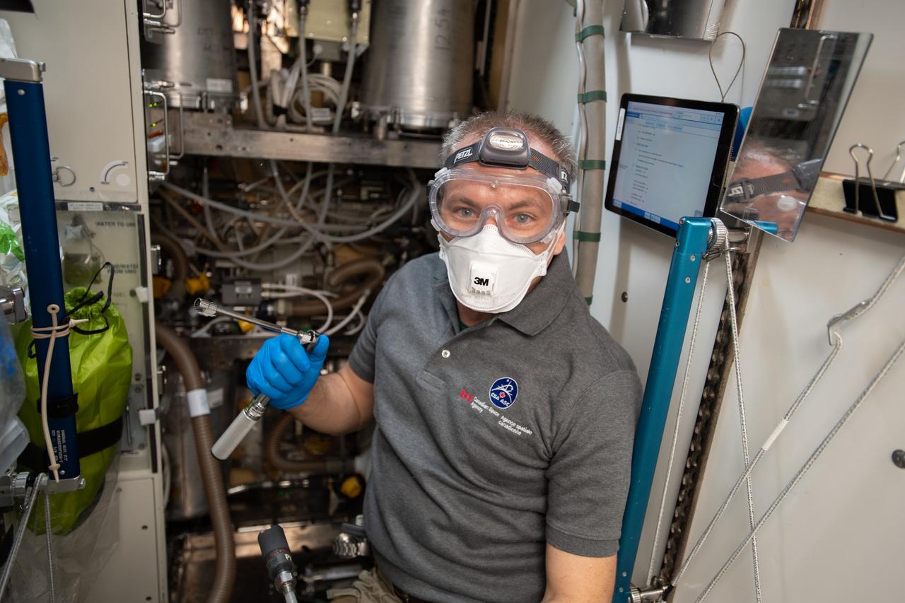
ISS030-E-032750 (11 Jan. 2012) --- NASA astronaut Dan Burbank, Expedition 30 flight commander, performs the Waste and Hygiene Compartment (WHC) yearly maintenance in the Tranquility node of the International Space Station. The maintenance included removing and replacing the urine hydraulic components which include urine lines, urine valve block and urine pressure sensors, and removing and replacing the Flush Water Tank Pressure Sensor.
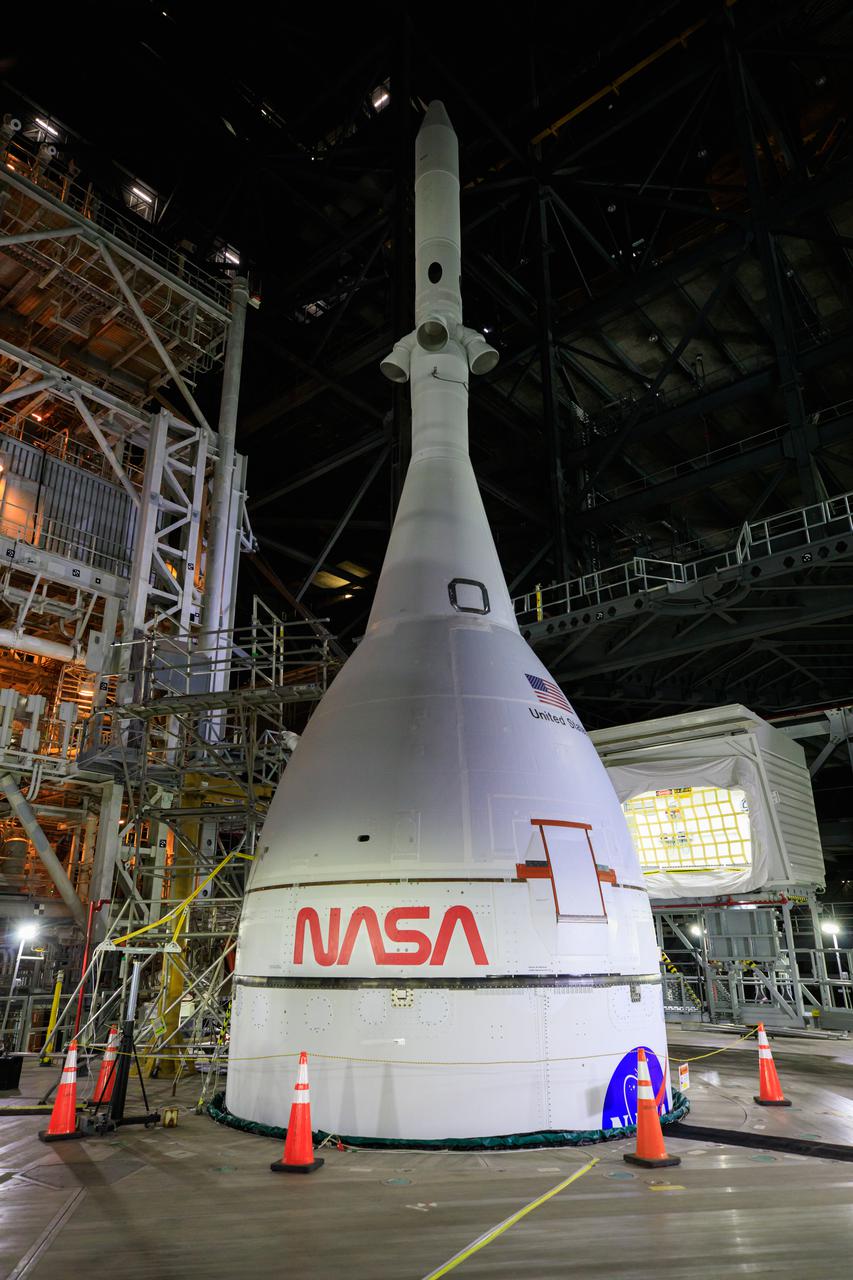
Teams retracted the first two of 20 platforms surrounding the Space Launch System rocket and Orion spacecraft that allow work on the integrated system in High Bay 3 inside the Vehicle Assembly Building at NASA’s Kennedy Space Center in Florida. The first platforms to be retracted – which move like hydraulic kitchen drawers when moved – are those located near the launch abort system on Orion in preparation for rollout to Launch Complex 39B for the Artemis I wet dress rehearsal.
KENNEDY SPACE CENTER, FLA. -- Liquid nitrogen lines are being used to freeze portions of Space Shuttle Atlantis' hydraulic lines leading to and from the Power Drive Unit (PDU) to prevent air intrusion during its removal. PDU replacement is expected to occur without impacting the April 24 launch date on mission STS-101

KENNEDY SPACE CENTER, FLA. -- Liquid nitrogen lines are being used to freeze portions of Space Shuttle Atlantis' hydraulic lines leading to and from the Power Drive Unit (PDU) to prevent air intrusion during its removal. PDU replacement is expected to occur without impacting the April 24 launch date on mission STS-101

KENNEDY SPACE CENTER, FLA. -- Liquid nitrogen lines are being used to freeze portions of Space Shuttle Atlantis' hydraulic lines leading to and from the Power Drive Unit (PDU) to prevent air intrusion during its removal. PDU replacement is expected to occur without impacting the April 24 launch date on mission STS-101
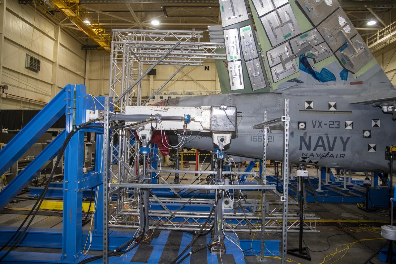
– Hydraulic actuators are pinned to horizontal tail test fixture for testing a F/A-18E from the Naval Air Systems Command (NAVAIR) in Patuxent River, Maryland. The aircraft is in NASA’s Armstrong Flight Research Center Flight Loads Laboratory in Edwards, California, for the center’s biggest load calibrations tests. This testing is needed before the aircraft can serve as a test vehicle for determining if it can safely manage maneuvers and proposed upgrades.
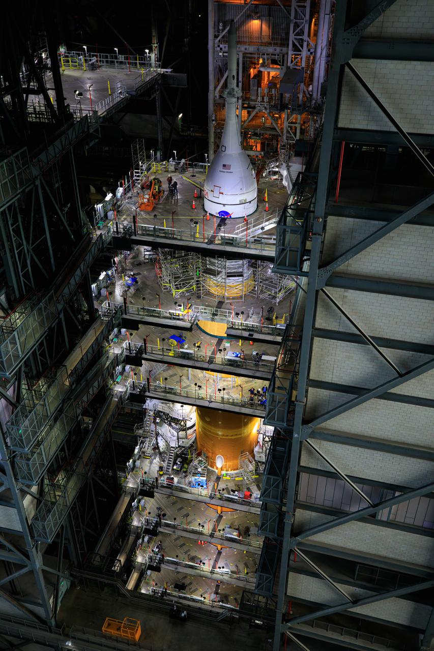
Teams retracted the first two of 20 platforms surrounding the Space Launch System rocket and Orion spacecraft that allow work on the integrated system in High Bay 3 inside the Vehicle Assembly Building at NASA’s Kennedy Space Center in Florida. The first platforms to be retracted – which move like hydraulic kitchen drawers when moved – are those located near the launch abort system on Orion in preparation for rollout to Launch Complex 39B for the Artemis I wet dress rehearsal.
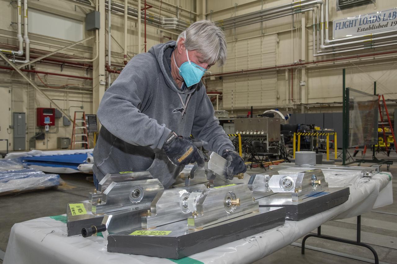
Assembled test structures called whiffle trees, which are needed to distribute prescribed hydraulic actuator loads, are attached to load pads to test the F/A-18E from the Naval Air Systems Command (NAVAIR) in Patuxent River, Maryland. The aircraft is in NASA’s Armstrong Flight Research Center Flight Loads Laboratory in Edwards, California, for the center’s biggest load calibrations tests. This testing is needed before the aircraft can serve as a test vehicle for determining if it can safely manage maneuvers and proposed upgrades.
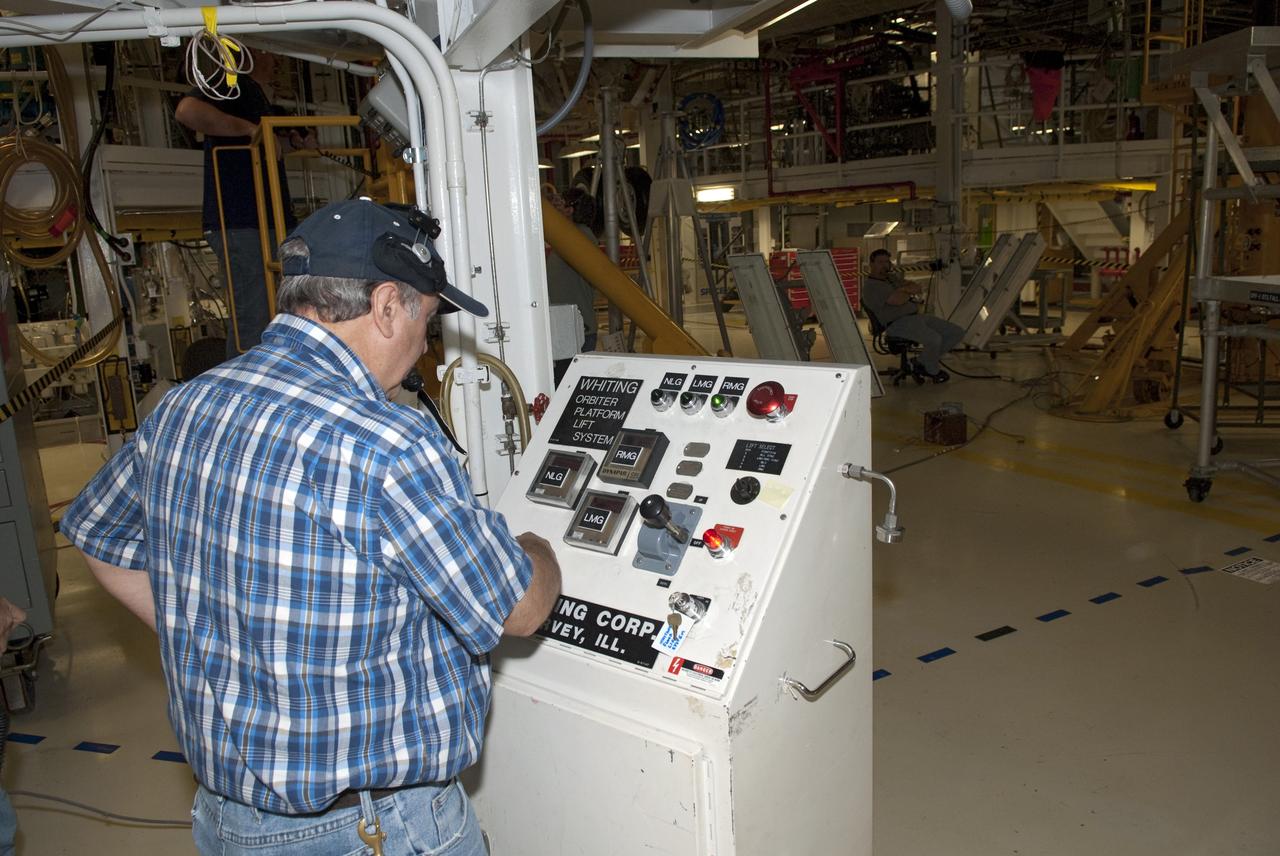
CAPE CANAVERAL, Fla. - In Orbiter Processing Facility-1 at NASA's Kennedy Space Center in Florida, a worker tests the hydraulic system that will lift the shuttle Atlantis off the floor to enable the orbiter transport system, or OTS, to be rolled underneath for its move, or "rollover," to the Vehicle Assembly Building. Once there Atlantis will be joined with the external fuel tank and solid rocket boosters on the mobile launcher platform. Atlantis is being prepared for the STS-135 mission, which will deliver the Raffaello multipurpose logistics module packed with supplies, logistics and spare parts to the International Space Station. STS-135 is targeted to launch June 28, and will be the last spaceflight for the Space Shuttle Program. Photo credit: NASA/Jim Grossmann
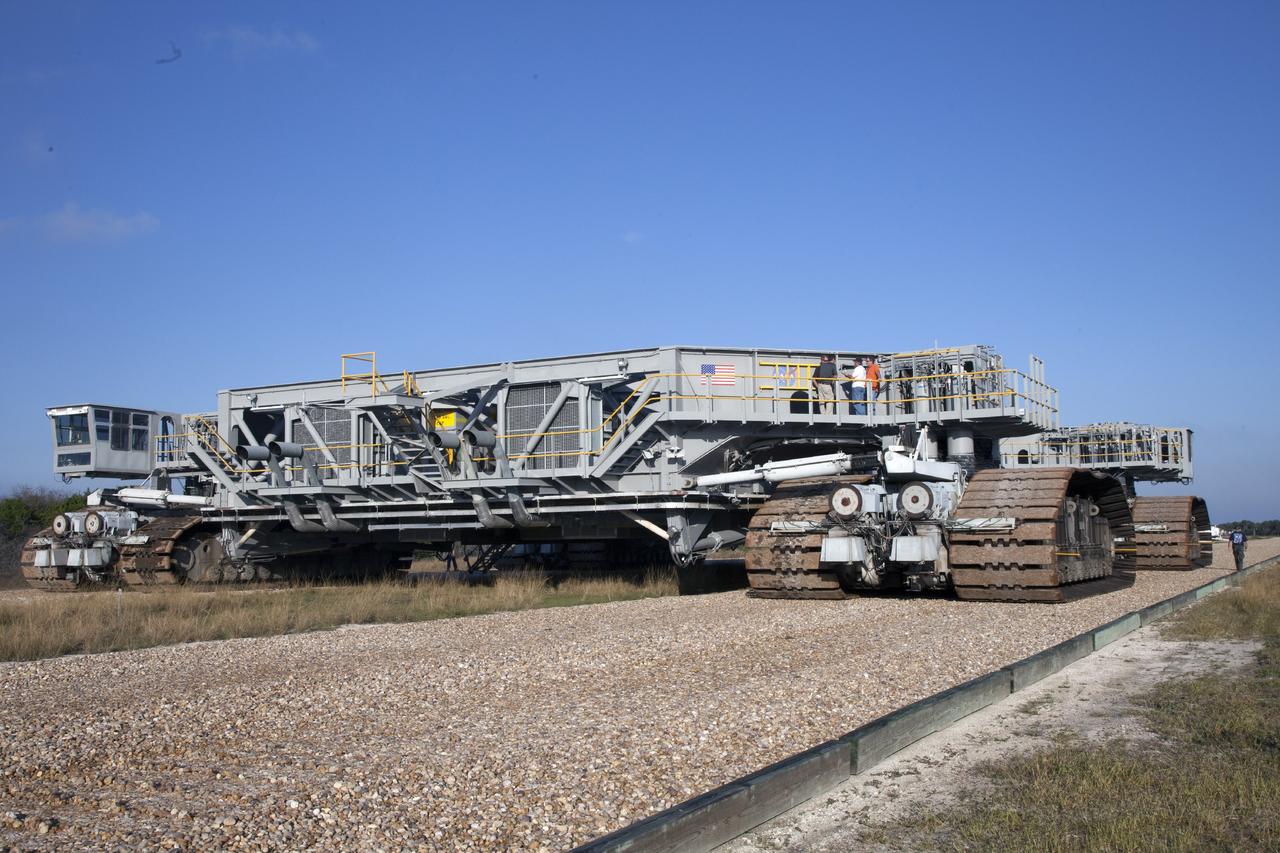
Crawler-transporter 2 (CT-2) moves slowly along the crawlerway on its way back to the Vehicle Assembly Building at NASA's Kennedy Space Center in Florida. The crawler took a trip to the Pad A/B split to test upgrades recently completed that will allow the giant vehicle to handle the load of the agency's Space Launch System rocket and Orion spacecraft atop the mobile launcher. The Ground Systems Development and Operations Program oversaw upgrades to the 50-year-old CT-2. New generators, gear assemblies, jacking, equalizing and leveling (JEL) hydraulic cylinders, roller bearings and brakes were installed, and other components were upgraded to prepare for Exploration Mission 1.
CAPE CANAVERAL, Fla. - In Orbiter Processing Facility-1 at NASA's Kennedy Space Center in Florida, workers install and test the hydraulic system that will lift the shuttle Atlantis off the floor to enable the orbiter transport system, or OTS, to be rolled underneath for its move, or "rollover," to the Vehicle Assembly Building. Once there Atlantis will be joined with the external fuel tank and solid rocket boosters on the mobile launcher platform. Atlantis is being prepared for the STS-135 mission, which will deliver the Raffaello multipurpose logistics module packed with supplies, logistics and spare parts to the International Space Station. STS-135 is targeted to launch June 28, and will be the last spaceflight for the Space Shuttle Program. Photo credit: NASA/Jim Grossmann
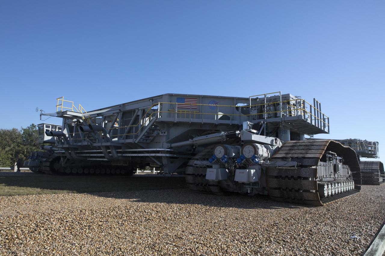
Crawler-transporter 2 (CT-2) moves slowly along the crawlerway on its way back to the Vehicle Assembly Building at NASA's Kennedy Space Center in Florida. The crawler took a trip to the Pad A/B split to test upgrades recently completed that will allow the giant vehicle to handle the load of the agency's Space Launch System rocket and Orion spacecraft atop the mobile launcher. The Ground Systems Development and Operations Program oversaw upgrades to the 50-year-old CT-2. New generators, gear assemblies, jacking, equalizing and leveling (JEL) hydraulic cylinders, roller bearings and brakes were installed, and other components were upgraded to prepare for Exploration Mission 1.
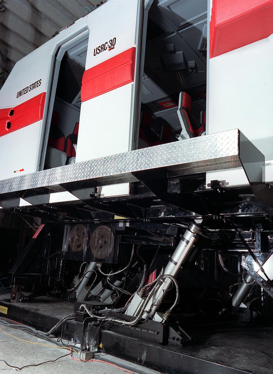
The development of the electric space actuator represents an unusual case of space technology transfer wherein the product was commercialized before it was used for the intended space purpose. MOOG, which supplies the thrust vector control hydraulic actuators for the Space Shuttle and brake actuators for the Space Orbiter, initiated development of electric actuators for aerospace and industrial use in the early 1980s. NASA used the technology to develop an electric replacement for the Space Shuttle main engine TVC actuator. An electric actuator is used to take passengers on a realistic flight to Jupiter at the US Space and Rocket Center, Huntsville, Alabama.
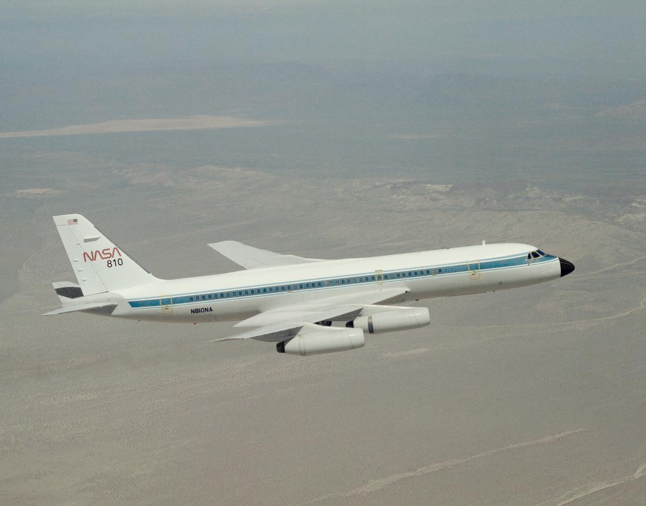
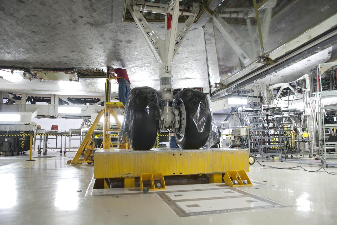
A NASA CV-990, modified as a Landing Systems Research Aircraft (LSRA), in flight over NASA's Dryden Flight Research Center, Edwards, California, for a test of the space shuttle landing gear system. The space shuttle landing gear test unit, operated by a high-pressure hydraulic system, allowed engineers to assess and document the performance of space shuttle main and nose landing gear systems, tires and wheel assemblies, plus braking and nose wheel steering performance. The series of 155 test missions for the space shuttle program provided extensive data about the life and endurance of the shuttle tire systems and helped raise the shuttle crosswind landing limits at Kennedy.
Crawler-transporter 2 (CT-2) moves slowly along the crawlerway toward the Vehicle Assembly Building (in the background) at NASA's Kennedy Space Center in Florida. The crawler took a trip to the Pad A/B split to test upgrades recently completed that will allow the giant vehicle to handle the load of the agency's Space Launch System rocket and Orion spacecraft atop the mobile launcher. The Ground Systems Development and Operations Program oversaw upgrades to the 50-year-old CT-2. New generators, gear assemblies, jacking, equalizing and leveling (JEL) hydraulic cylinders, roller bearings and brakes were installed, and other components were upgraded to prepare for Exploration Mission 1.
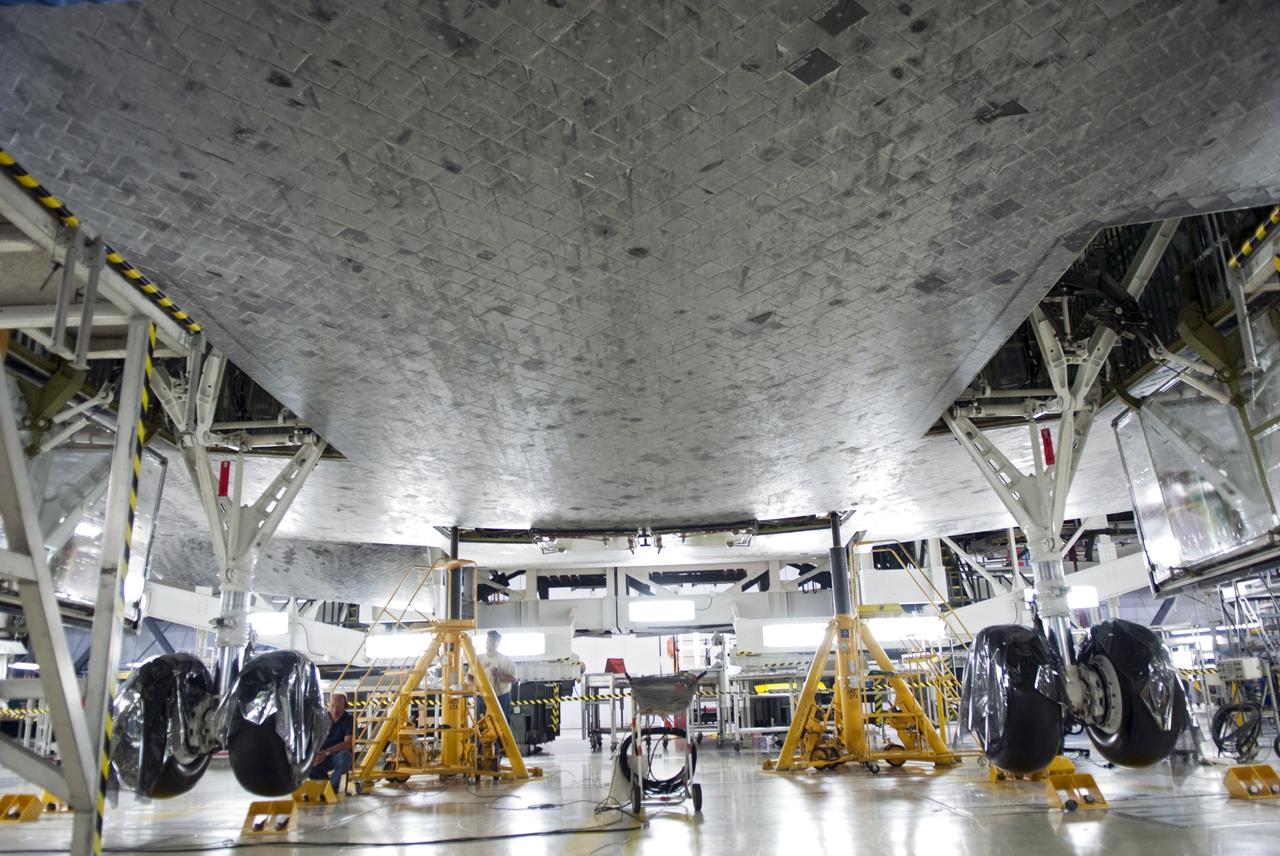
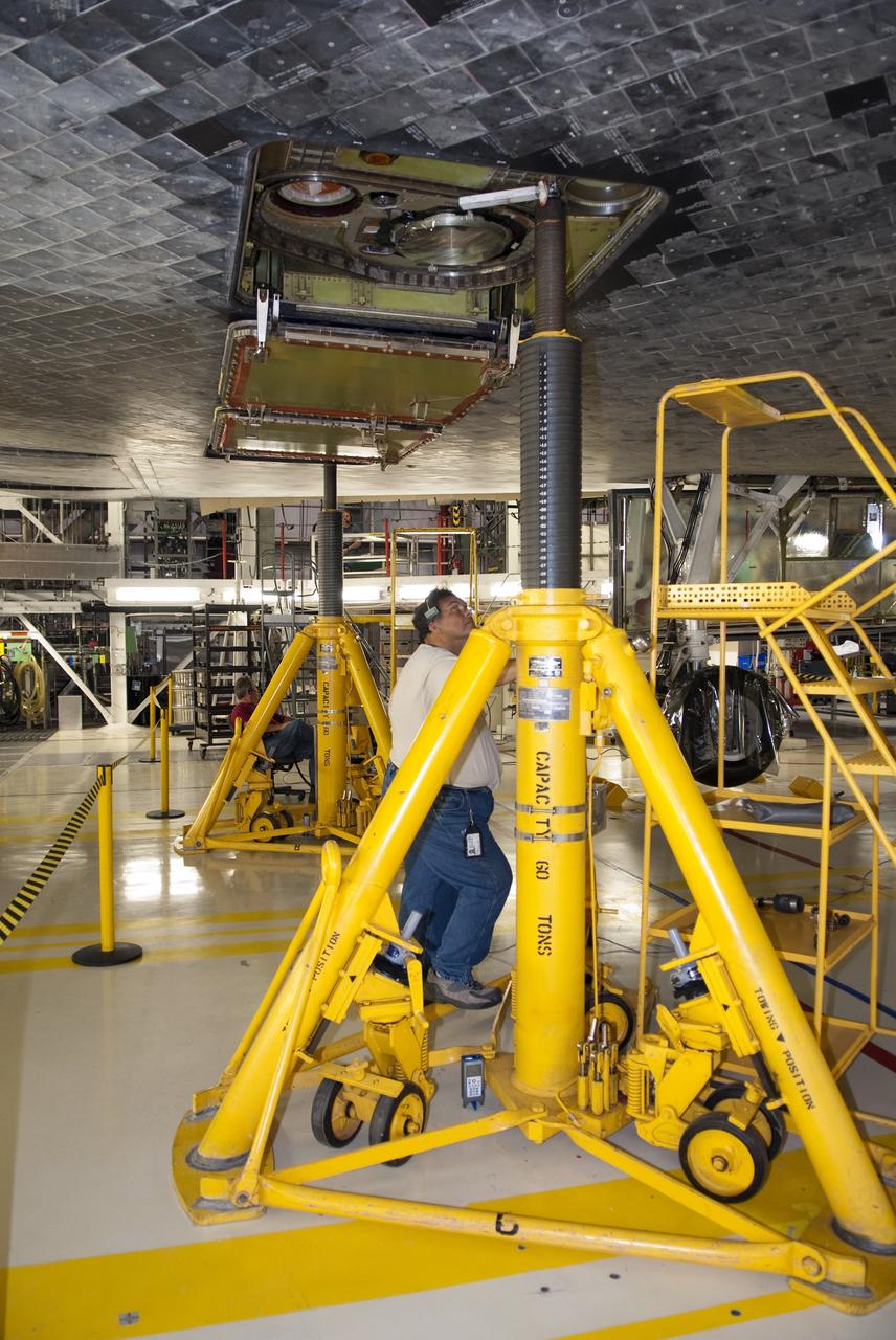
CAPE CANAVERAL, Fla. - In Orbiter Processing Facility-1 at NASA's Kennedy Space Center in Florida, a hydraulic system has lifted shuttle Atlantis off the floor to enable the orbiter transport system, or OTS, to be rolled underneath for its move, or "rollover," to the Vehicle Assembly Building. Once there Atlantis will be joined with the external fuel tank and solid rocket boosters on the mobile launcher platform. Atlantis is being prepared for the STS-135 mission, which will deliver the Raffaello multipurpose logistics module packed with supplies, logistics and spare parts to the International Space Station. STS-135 is targeted to launch June 28, and will be the last spaceflight for the Space Shuttle Program. Photo credit: NASA/Jim Grossmann
CAPE CANAVERAL, Fla. - In Orbiter Processing Facility-1 at NASA's Kennedy Space Center in Florida, a worker checks the hydraulic system that has lifted shuttle Atlantis off the floor to enable the orbiter transport system, or OTS, to be rolled underneath for its move, or "rollover," to the Vehicle Assembly Building. Once there Atlantis will be joined with the external fuel tank and solid rocket boosters on the mobile launcher platform. Atlantis is being prepared for the STS-135 mission, which will deliver the Raffaello multipurpose logistics module packed with supplies, logistics and spare parts to the International Space Station. STS-135 is targeted to launch June 28, and will be the last spaceflight for the Space Shuttle Program. Photo credit: NASA/Jim Grossmann
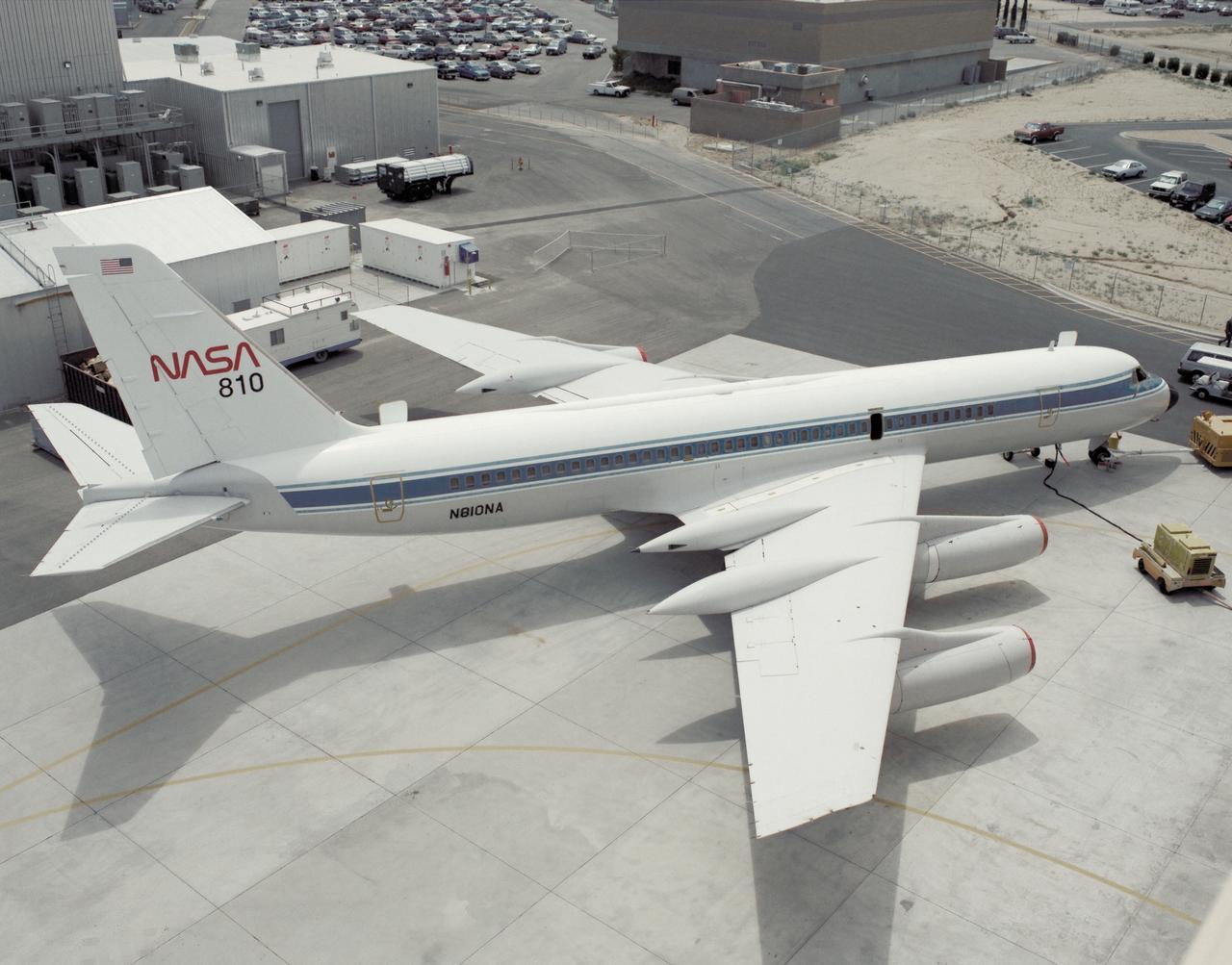
A NASA CV-990, modified as a Landing Systems Research Aircraft (LSRA), is serviced on the ramp at NASA's Dryden Flight Research Center, Edwards, California, before a test of the space shuttle landing gear system. The space shuttle landing gear test unit, operated by a high-pressure hydraulic system, allowed engineers to assess and document the performance of space shuttle main and nose landing gear systems, tires and wheel assemblies, plus braking and nose wheel steering performance. The series of 155 test missions for the space shuttle program provided extensive data about the life and endurance of the shuttle tire systems and helped raise the shuttle crosswind landing limits at Kennedy.
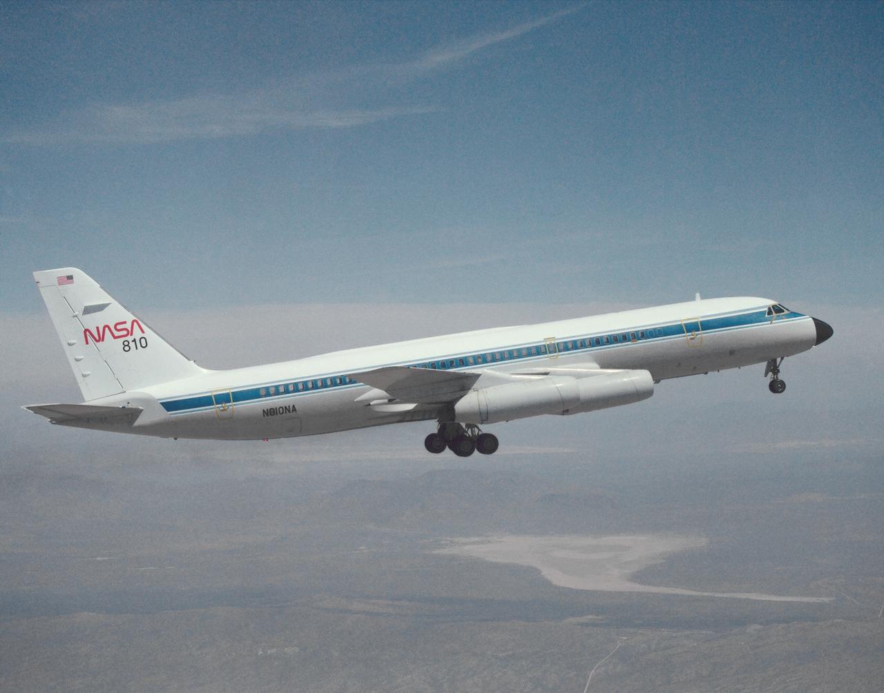
A NASA CV-990, modified as a Landing Systems Research Aircraft (LSRA), in flight over NASA's Dryden Flight Research Center, Edwards, California, for a test of the space shuttle landing gear system. The space shuttle landing gear test unit, operated by a high-pressure hydraulic system, allowed engineers to assess and document the performance of space shuttle main and nose landing gear systems, tires and wheel assemblies, plus braking and nose wheel steering performance. The series of 155 test missions for the space shuttle program provided extensive data about the life and endurance of the shuttle tire systems and helped raise the shuttle crosswind landing limits at Kennedy.
Crawler-transport 2 (CT-2) moves slowly along the crawlerway on its way back to the Vehicle Assembly Building at NASA's Kennedy Space Center in Florida. The crawler took a trip to the pad A/B split to test upgrades recently completed that will allow the giant vehicle to handle the load of the agency's Space Launch System rocket and Orion spacecraft atop the mobile launcher. The Ground Systems Development and Operations Program oversaw upgrades to the 50-year-old CT-2. New generators, gear assemblies, jacking, equalizing and leveling (JEL) hydraulic cylinders, roller bearings and brakes were installed, and other components were upgraded to prepare for Exploration Mission 1.
CAPE CANAVERAL, Fla. - In Orbiter Processing Facility-1 at NASA's Kennedy Space Center in Florida, a worker checks the hydraulic system that has lifted shuttle Atlantis off the floor to enable the orbiter transport system, or OTS, to be rolled underneath for its move, or "rollover," to the Vehicle Assembly Building. Once there Atlantis will be joined with the external fuel tank and solid rocket boosters on the mobile launcher platform. Atlantis is being prepared for the STS-135 mission, which will deliver the Raffaello multipurpose logistics module packed with supplies, logistics and spare parts to the International Space Station. STS-135 is targeted to launch June 28, and will be the last spaceflight for the Space Shuttle Program. Photo credit: NASA/Jim Grossmann
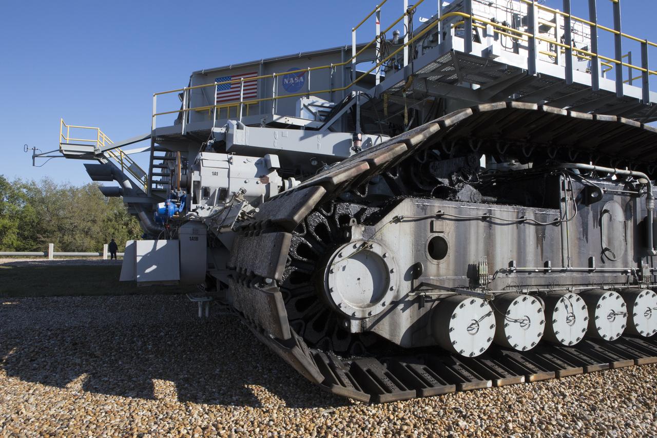
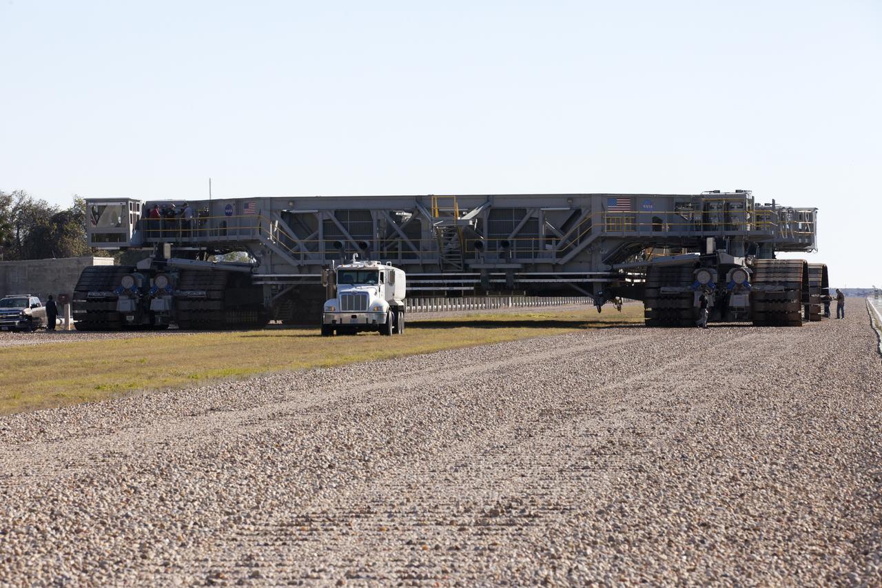
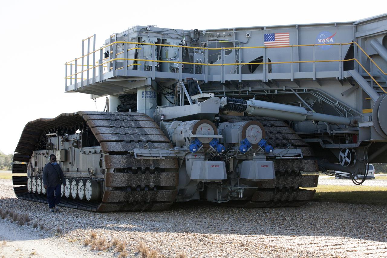
CAPE CANAVERAL, Fla. -- Crawler-transporter 1 continues its trek on the crawlerway to Launch Pad 39A at NASA’s Kennedy Space Center in Florida. New jacking, equalizing and leveling, or JEL, hydraulic cylinders were installed on CT-1 and will be tested for increased load carrying capacity and reliability. The Ground Systems Development and Operations Program at Kennedy continues to upgrade the crawler-transporter as part of its general maintenance. CT-1 could be available to carry a variety of launch vehicles to the launch pad. Two crawler-transporters were used to carry the mobile launcher platform and space shuttle to Launch Complex 39 for space shuttle launches for 30 years. Photo credit: NASA/Jim Grossmann
A full view of crawler-transporter 2 (CT-2) as it moves slowly along the crawlerway on its way back to the Vehicle Assembly Building at NASA's Kennedy Space Center in Florida. The crawler took a trip to the Pad A/B split to test upgrades recently completed that will allow the giant vehicle to handle the load of the agency's Space Launch System rocket and Orion spacecraft atop the mobile launcher. The Ground Systems Development and Operations Program oversaw upgrades to the 50-year-old CT-2. New generators, gear assemblies, jacking, equalizing and leveling (JEL) hydraulic cylinders, roller bearings and brakes were installed, and other components were upgraded to prepare for Exploration Mission 1.
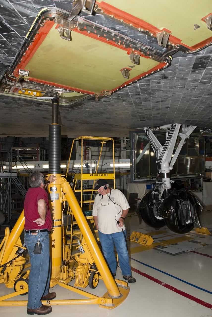
CAPE CANAVERAL, Fla. - In Orbiter Processing Facility-1 at NASA's Kennedy Space Center in Florida, workers test the hydraulic system that will lift the shuttle Atlantis off the floor to enable the orbiter transport system, or OTS, to be rolled underneath for its move, or "rollover," to the Vehicle Assembly Building. Once there Atlantis will be joined with the external fuel tank and solid rocket boosters on the mobile launcher platform. Atlantis is being prepared for the STS-135 mission, which will deliver the Raffaello multipurpose logistics module packed with supplies, logistics and spare parts to the International Space Station. STS-135 is targeted to launch June 28, and will be the last spaceflight for the Space Shuttle Program. Photo credit: NASA/Jim Grossmann
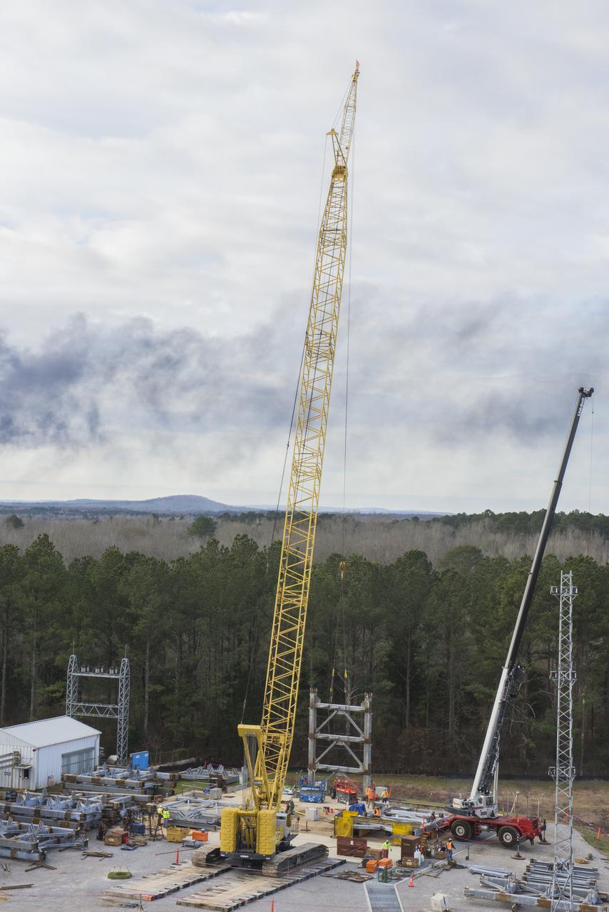
A CRANE MOVES THE FIRST STEEL TIER TO BE BOLTED INTO PLACE ON JAN. 6, FOR WELDING OF A SECOND NEW STRUCTURAL TEST STAND AT NASA'S MARSHALL SPACE FLIGHT CENTER IN HUNTSVILLE, ALABAMA -- CRITICAL TO DEVELOPMENT OF NASA'S SPACE LAUNCH SYSTEM. WHEN COMPLETED THIS SUMMER, THE 85-FOOT-TALL TEST STAND 4697 WILL USE HYDRAULIC CYLINDERS TO SUBJECT THE LIQUID OXYGEN TANK AND HARDWARE OF THE MASSIVE SLS CORE STAGE TO THE SAME LOADS AND STRESSES IT WILL ENDURE DURING A LAUNCH. THE STAND IS RISING IN MARSHALL'S WEST TEST AREA, WHERE WORK IS ALSO UNDERWAY ON THE 215-FOOT-TALL TOWERS OF TEST STAND 4693, WHICH WILL CONDUCT SIMILAR STRUCTURAL TESTS ON THE SLS CORE STAGE'S LIQUID HYDROGEN TANK. SLS, THE MOST POWERFUL ROCKET EVER BUILT, WILL CARRY ASTRONAUTS IN NASA'S ORION SPACECRAFT ON DEEP SPACE MISSIONS, INCLUDING THE JOURNEY TO MARS.
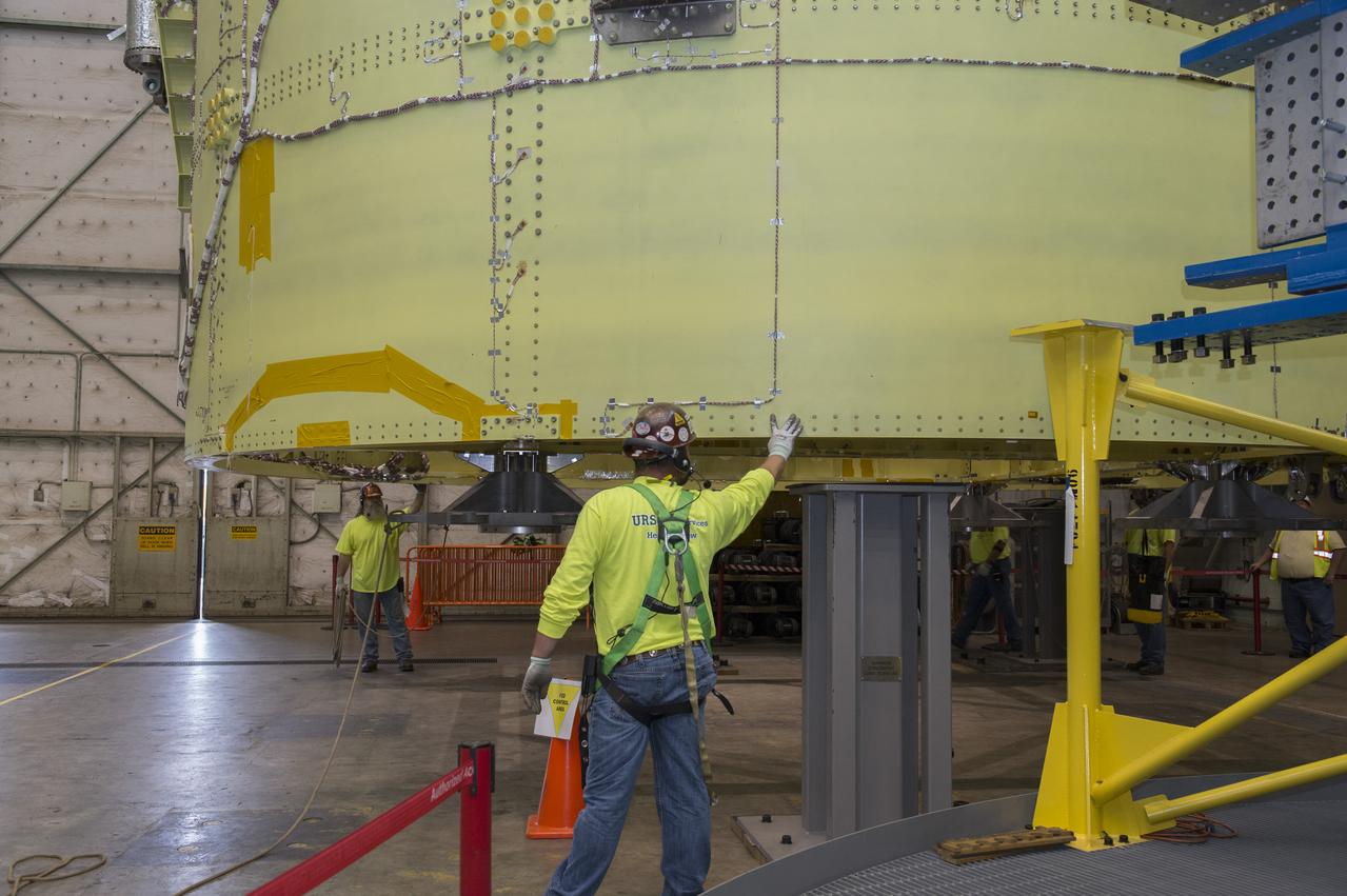
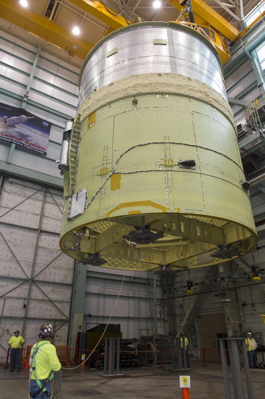
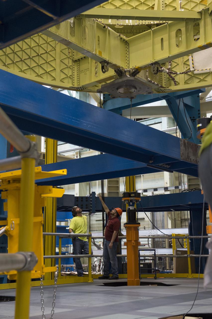
NASA engineers install test hardware for the agency's new heavy lift rocket, the Space Launch System, into a newly constructed 50-foot structural test stand at NASA's Marshall Space Flight Center. In the stand, hydraulic cylinders will be electronically controlled to push, pull, twist and bend the test article with millions of pounds of force. Engineers will record and analyze over 3,000 channels of data for each test case to verify the capabilities of the engine section and validate that the design and analysis models accurately predict the amount of loads the core stage can withstand during launch and ascent. The engine section, recently delivered via NASA's barge Pegasus from NASA's Michoud Assembly Facility, is the first of four core stage structural test articles scheduled to be delivered to Marshall for testing. The engine section, located at the bottom of SLS's massive core stage, will house the rocket's four RS-25 engines and be an attachment point for the two solid rocket boosters.
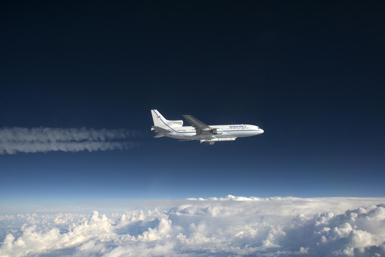
Photographed from the F-18 pathfinder aircraft, the Orbital ATK L-1011 Stargazer aircraft is seen flying over the Atlantic Ocean offshore from Daytona Beach, Florida. Attached beneath the aircraft is the Pegasus XL rocket with eight Cyclone Global Navigation Satellite System, or CYGNSS, spacecraft. The CYGNSS satellites will make frequent and accurate measurements of ocean surface winds throughout the life cycle of tropical storms and hurricanes. The data that CYGNSS provides will enable scientists to probe key air-sea interaction processes that take place near the core of storms, which are rapidly changing and play a crucial role in the beginning and intensification of hurricanes. NOTE: The Dec. 12, 2016 launch attempt was postponed due to a hydraulic pump aboard the Orbital ATK L-1011 aircraft which is required to release the latches holding Pegasus in place, is not receiving power.
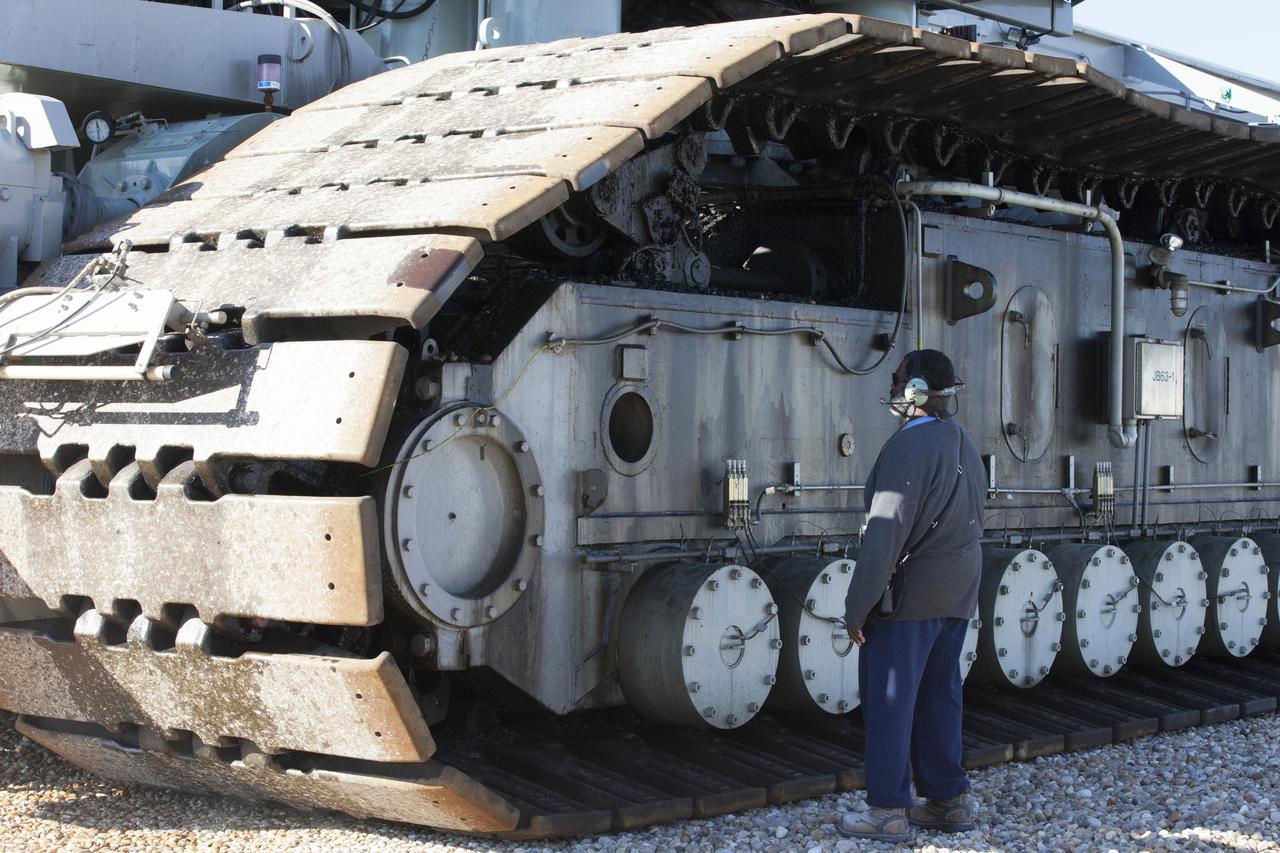
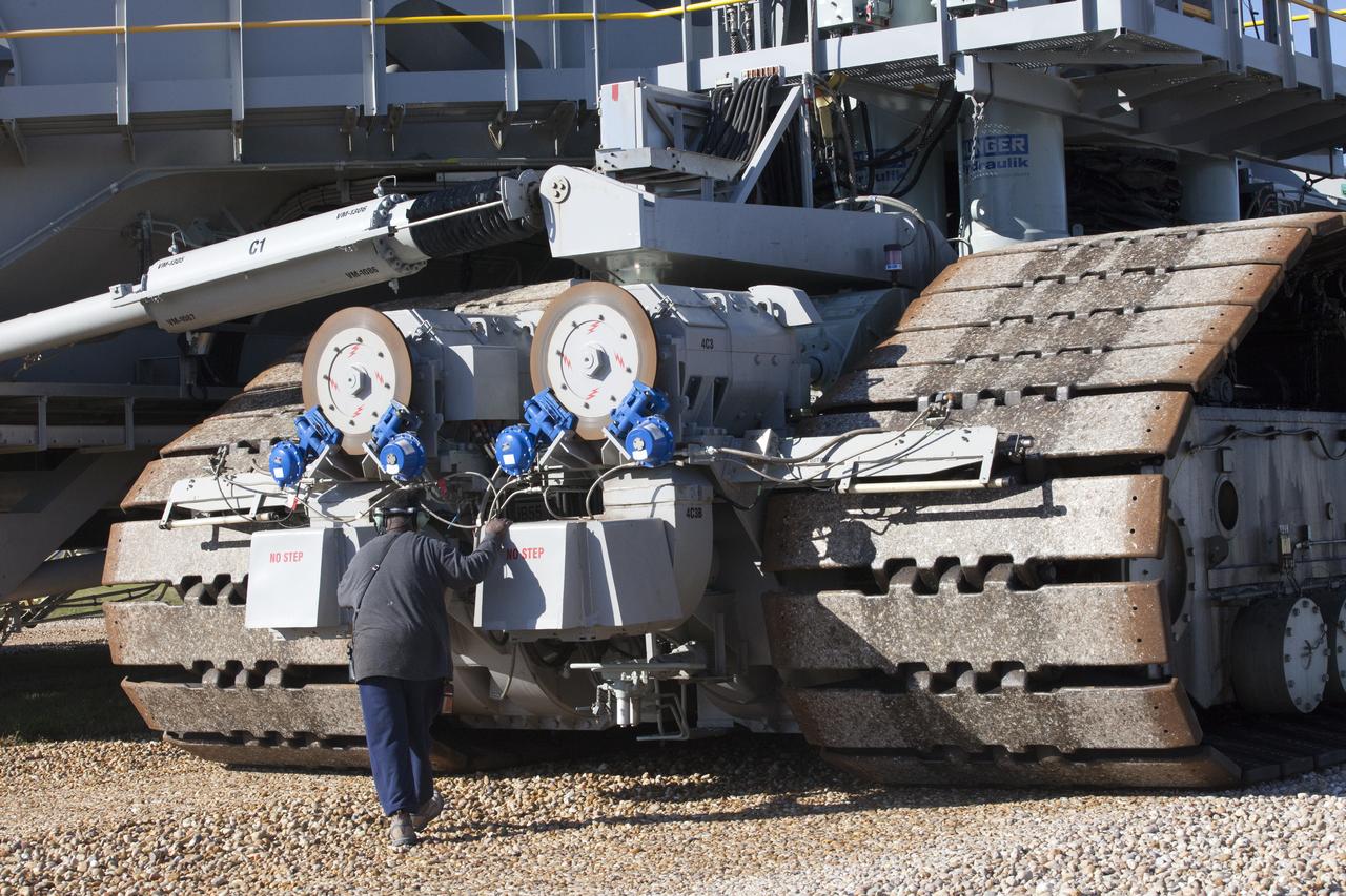
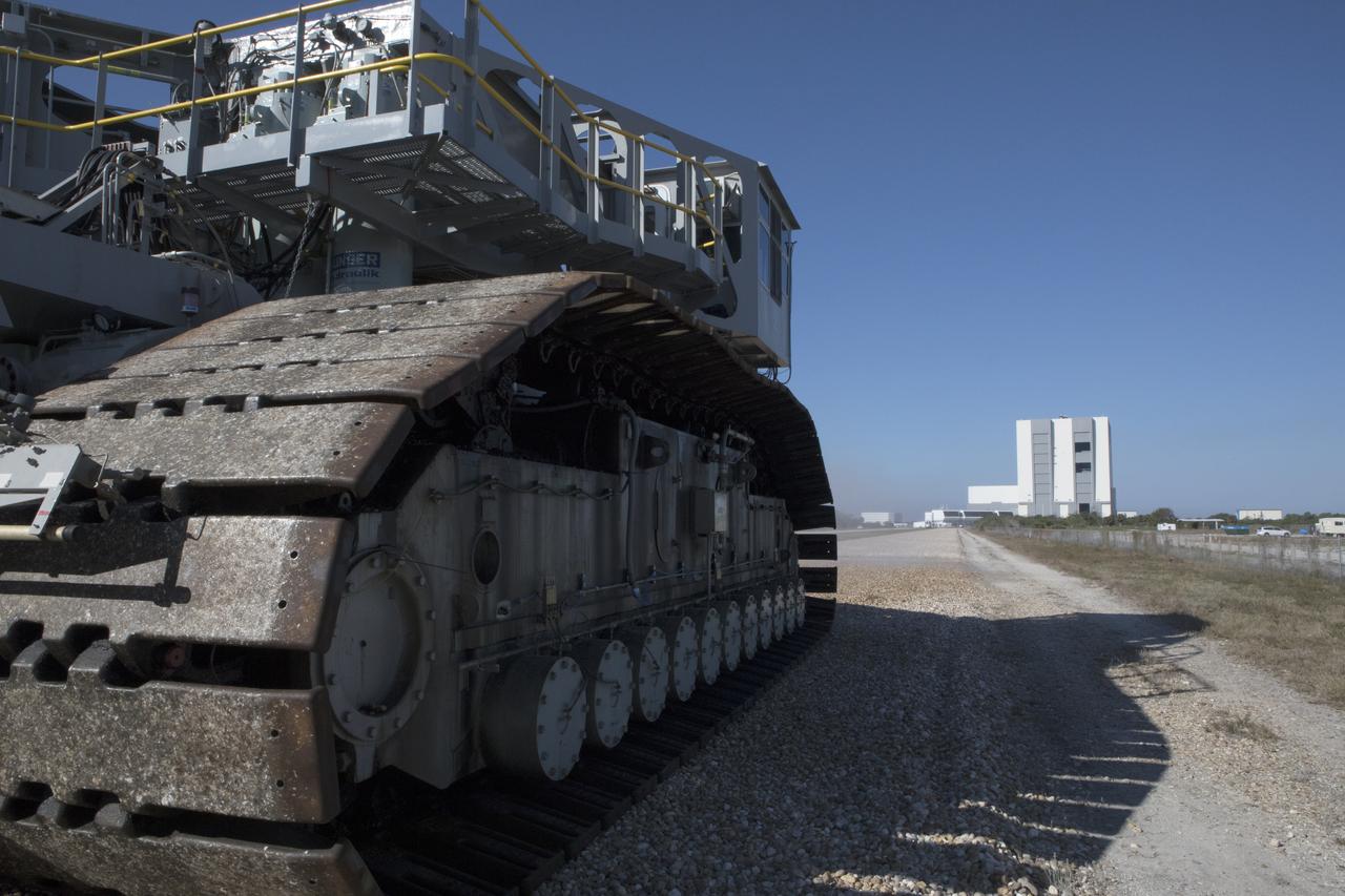
A ground support technician checks the giant treads on crawler-transporter 2 (CT-2) as the vehicle moves slowly along the crawlerway toward the Vehicle Assembly Building at NASA's Kennedy Space Center in Florida. The crawler took a trip to the pad A/B split to test upgrades recently completed that will allow the giant vehicle to handle the load of the agency's Space Launch System rocket and Orion spacecraft atop the mobile launcher. The Ground Systems Development and Operations Program oversaw upgrades to the 50-year-old CT-2. New generators, gear assemblies, jacking, equalizing and leveling (JEL) hydraulic cylinders, roller bearings and brakes were installed, and other components were upgraded to prepare for Exploration Mission 1.
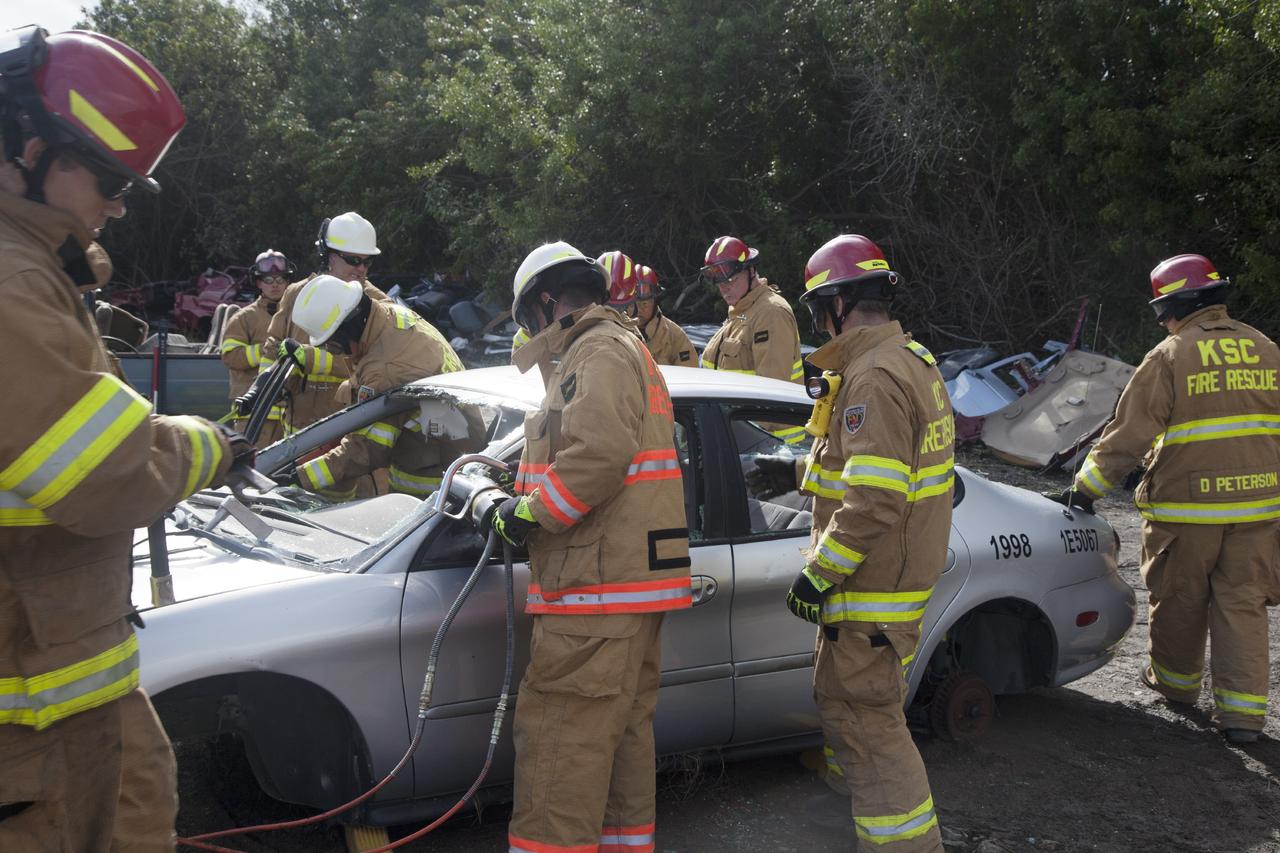
CAPE CANAVERAL, Fla. – Special Rescue Operations firefighters with NASA Fire Rescue Services in the Protective Services Office at NASA’s Kennedy Space Center in Florida practice vehicle extrication training at an auto salvage yard near the center. A firefighter uses a special hydraulic tool to cut through a section of the car to remove the roof, while other firefighters clear the windows and prepare to use the Jaws of Life to simulate the rescue of a trapped and injured person. Other rescue equipment being used includes axes and tools to punch through and clear away windshields and windows. Kennedy’s firefighters recently achieved Pro Board Certification in aerial fire truck operations. With the completion of vehicle extrication and Jaws of Life training, the Protective Services Office is one step closer to achieving certification in vehicle machinery extrication. Kennedy’s firefighters are with G4S Government Solutions Inc., on the Kennedy Protective Services Contract. Photo credit: NASA/Daniel Casper
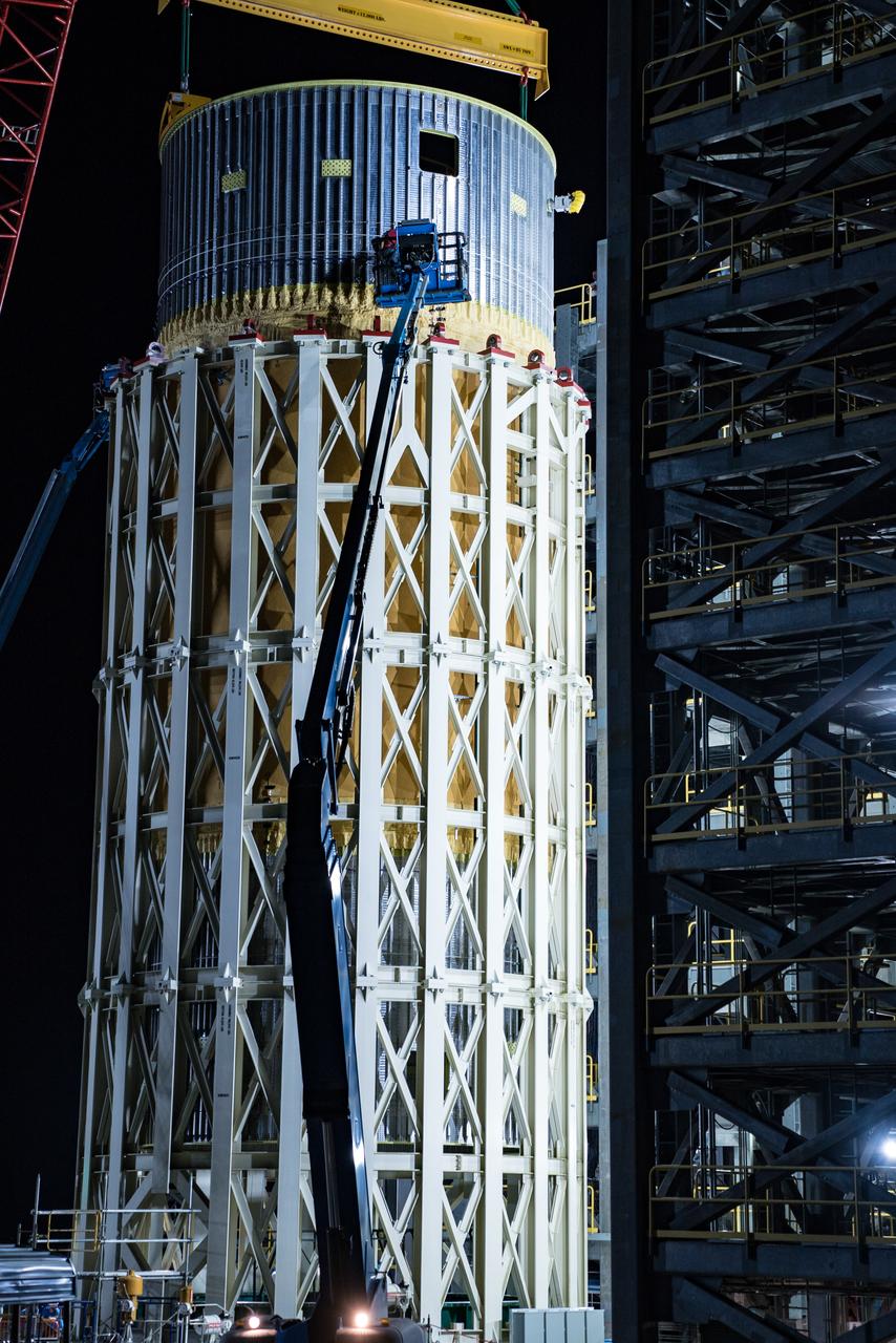
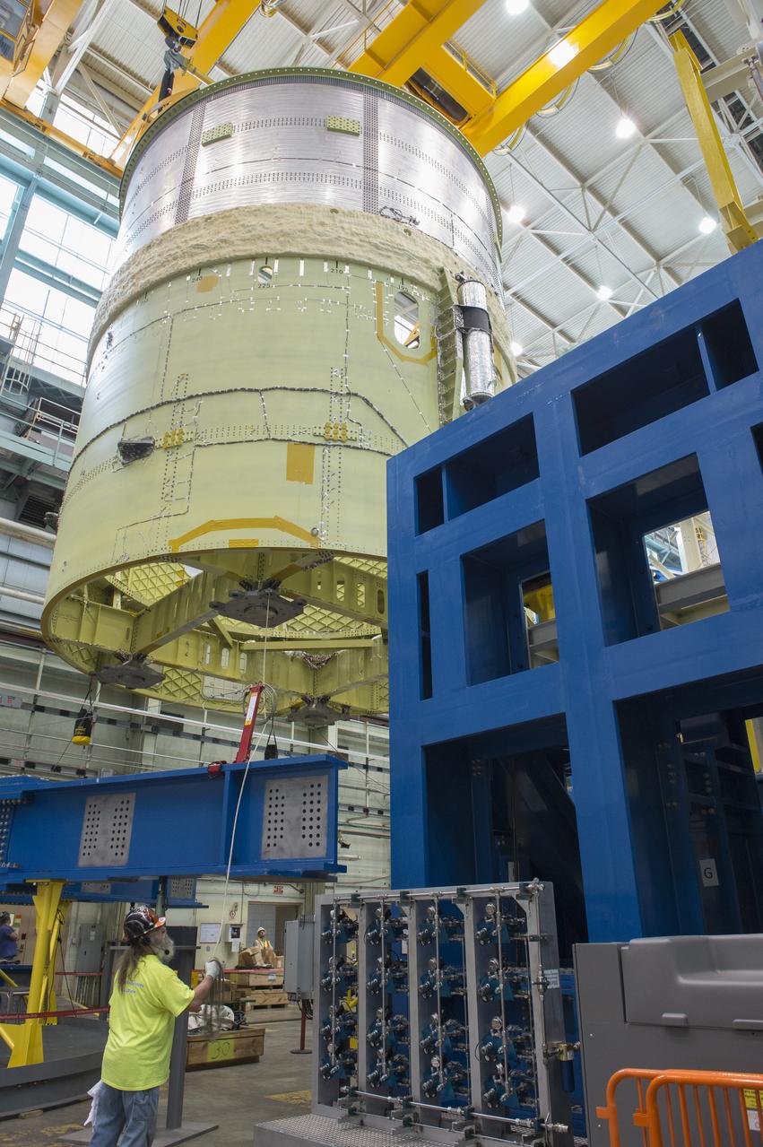
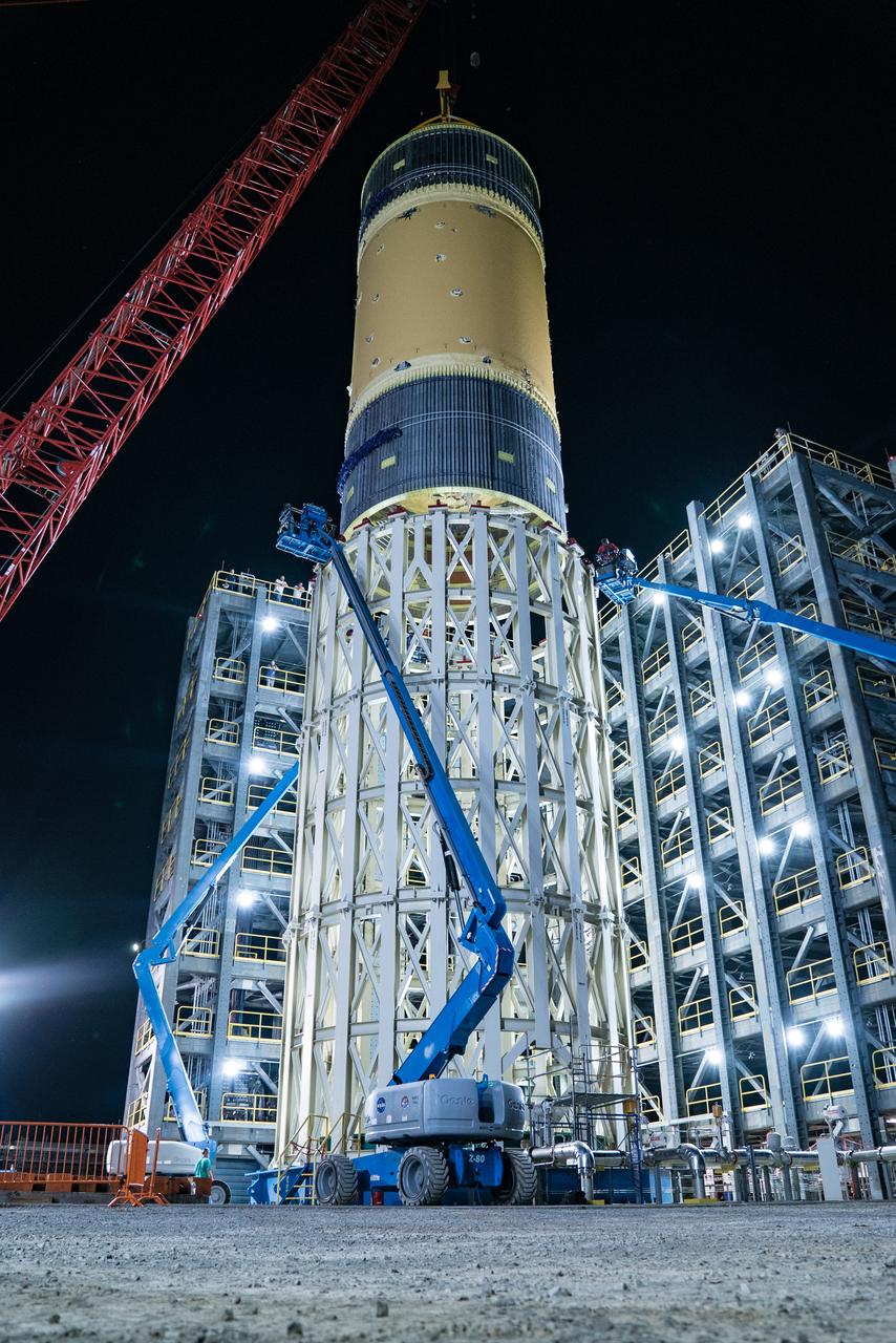
This collection of photos shows the steps NASA engineers took to lift the final structural test article for NASA’s Space Launch System (SLS) core stage into Test Stand 4697 at NASA’s Marshall Space Flight Center in Huntsville, Alabama, July 10, 2019. The liquid oxygen (LOX) tank is one of two propellant tanks in the rocket’s massive core stage that will produce more than 2 million pounds of thrust to help launch Artemis 1, the first flight of NASA’s Orion spacecraft and SLS, to the Moon. The nearly 70-foot-long liquid oxygen tank structural test article was manufactured at NASA’s Michoud Assembly Facility in New Orleans and delivered by NASA’s barge Pegasus to Marshall. Once bolted into the test stand, dozens of hydraulic cylinders will push and pull the tank, subjecting it to the same stresses and forces it will endure during liftoff and flight, to verify it is fit for flight.
A ground support technician walks alongside crawler-transporter 2 (CT-2) as the vehicle moves slowly along the crawlerway toward the Vehicle Assembly Building at NASA's Kennedy Space Center in Florida. The crawler took a trip to the Pad A/B split to test upgrades recently completed that will allow the giant vehicle to handle the load of the agency's Space Launch System rocket and Orion spacecraft atop the mobile launcher. The Ground Systems Development and Operations Program oversaw upgrades to the 50-year-old CT-2. New generators, gear assemblies, jacking, equalizing and leveling (JEL) hydraulic cylinders, roller bearings and brakes were installed, and other components were upgraded to prepare for Exploration Mission 1.
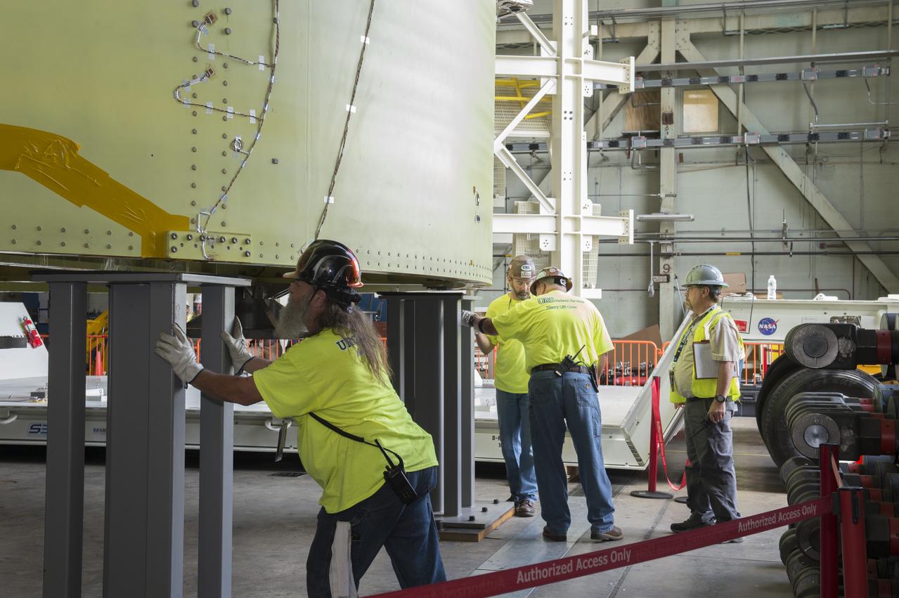
NASA engineers install test hardware for the agency's new heavy lift rocket, the Space Launch System, into a newly constructed 50-foot structural test stand at NASA's Marshall Space Flight Center. In the stand, hydraulic cylinders will be electronically controlled to push, pull, twist and bend the test article with millions of pounds of force. Engineers will record and analyze over 3,000 channels of data for each test case to verify the capabilities of the engine section and validate that the design and analysis models accurately predict the amount of loads the core stage can withstand during launch and ascent. The engine section, recently delivered via NASA's barge Pegasus from NASA's Michoud Assembly Facility, is the first of four core stage structural test articles scheduled to be delivered to Marshall for testing. The engine section, located at the bottom of SLS's massive core stage, will house the rocket's four RS-25 engines and be an attachment point for the two solid rocket boosters.
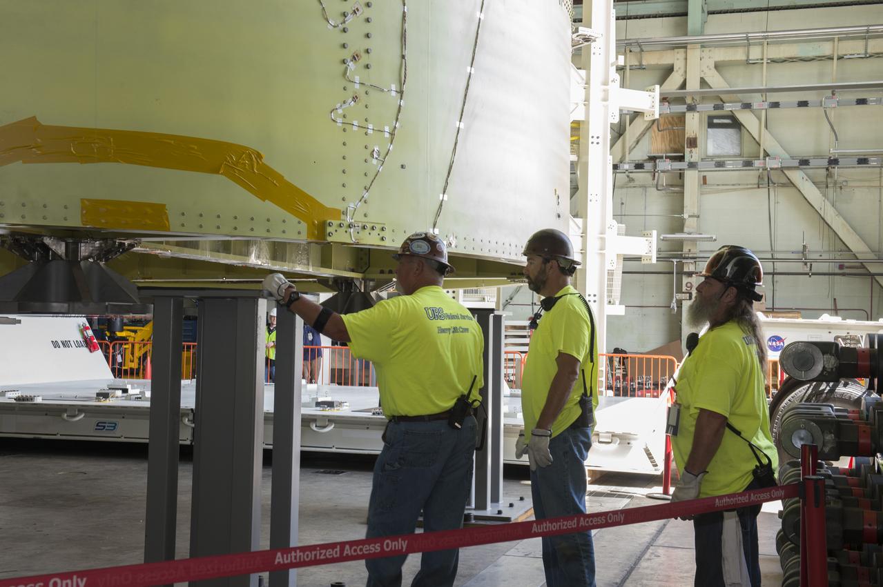
NASA engineers install test hardware for the agency's new heavy lift rocket, the Space Launch System, into a newly constructed 50-foot structural test stand at NASA's Marshall Space Flight Center. In the stand, hydraulic cylinders will be electronically controlled to push, pull, twist and bend the test article with millions of pounds of force. Engineers will record and analyze over 3,000 channels of data for each test case to verify the capabilities of the engine section and validate that the design and analysis models accurately predict the amount of loads the core stage can withstand during launch and ascent. The engine section, recently delivered via NASA's barge Pegasus from NASA's Michoud Assembly Facility, is the first of four core stage structural test articles scheduled to be delivered to Marshall for testing. The engine section, located at the bottom of SLS's massive core stage, will house the rocket's four RS-25 engines and be an attachment point for the two solid rocket boosters.
KENNEDY SPACE CENTER, FLA. -- In Orbiter Processing Facility bay 3, United Space Alliance and B.F. Goodrich technicians begin work on the starboard landing gear assembly of space shuttle Discovery. They will replace a leaking dynamic seal in Discovery's right main-gear strut. The struts act as shock absorbers during the shuttle's landing. Engineers determined the observed leak of hydraulic fluid in the main landing gear strut exceeded specification and could not be reduced to an acceptable rate. Removing the strut and replacing seals require disconnecting and replacing the brakes and tires, disconnecting and reconnecting instruments and other requirements to allow access to the strut. Discovery had been scheduled to roll over Sept. 19 from its processing hangar to the Vehicle Assembly Building. A new rollover date will be set after technicians determine how long replacing the seal will take. Photo credit: NASA/George Shelton
NASA engineers install test hardware for the agency's new heavy lift rocket, the Space Launch System, into a newly constructed 50-foot structural test stand at NASA's Marshall Space Flight Center. In the stand, hydraulic cylinders will be electronically controlled to push, pull, twist and bend the test article with millions of pounds of force. Engineers will record and analyze over 3,000 channels of data for each test case to verify the capabilities of the engine section and validate that the design and analysis models accurately predict the amount of loads the core stage can withstand during launch and ascent. The engine section, recently delivered via NASA's barge Pegasus from NASA's Michoud Assembly Facility, is the first of four core stage structural test articles scheduled to be delivered to Marshall for testing. The engine section, located at the bottom of SLS's massive core stage, will house the rocket's four RS-25 engines and be an attachment point for the two solid rocket boosters.
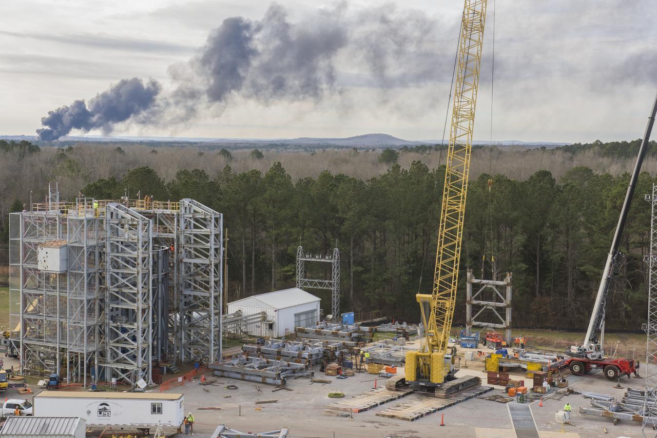
A CRANE MOVES THE FIRST STEEL TIER TO BE BOLTED INTO PLACE ON JAN. 6, FOR WELDING OF A SECOND NEW STRUCTURAL TEST STAND AT NASA'S MARSHALL SPACE FLIGHT CENTER IN HUNTSVILLE, ALABAMA -- CRITICAL TO DEVELOPMENT OF NASA'S SPACE LAUNCH SYSTEM. WHEN COMPLETED THIS SUMMER, THE 85-FOOT-TALL TEST STAND 4697 WILL USE HYDRAULIC CYLINDERS TO SUBJECT THE LIQUID OXYGEN TANK AND HARDWARE OF THE MASSIVE SLS CORE STAGE TO THE SAME LOADS AND STRESSES IT WILL ENDURE DURING A LAUNCH. THE STAND IS RISING IN MARSHALL'S WEST TEST AREA, WHERE WORK IS ALSO UNDERWAY ON THE 215-FOOT-TALL TOWERS OF TEST STAND 4693, WHICH WILL CONDUCT SIMILAR STRUCTURAL TESTS ON THE SLS CORE STAGE'S LIQUID HYDROGEN TANK. SLS, THE MOST POWERFUL ROCKET EVER BUILT, WILL CARRY ASTRONAUTS IN NASA'S ORION SPACECRAFT ON DEEP SPACE MISSIONS, INCLUDING THE JOURNEY TO MARS.
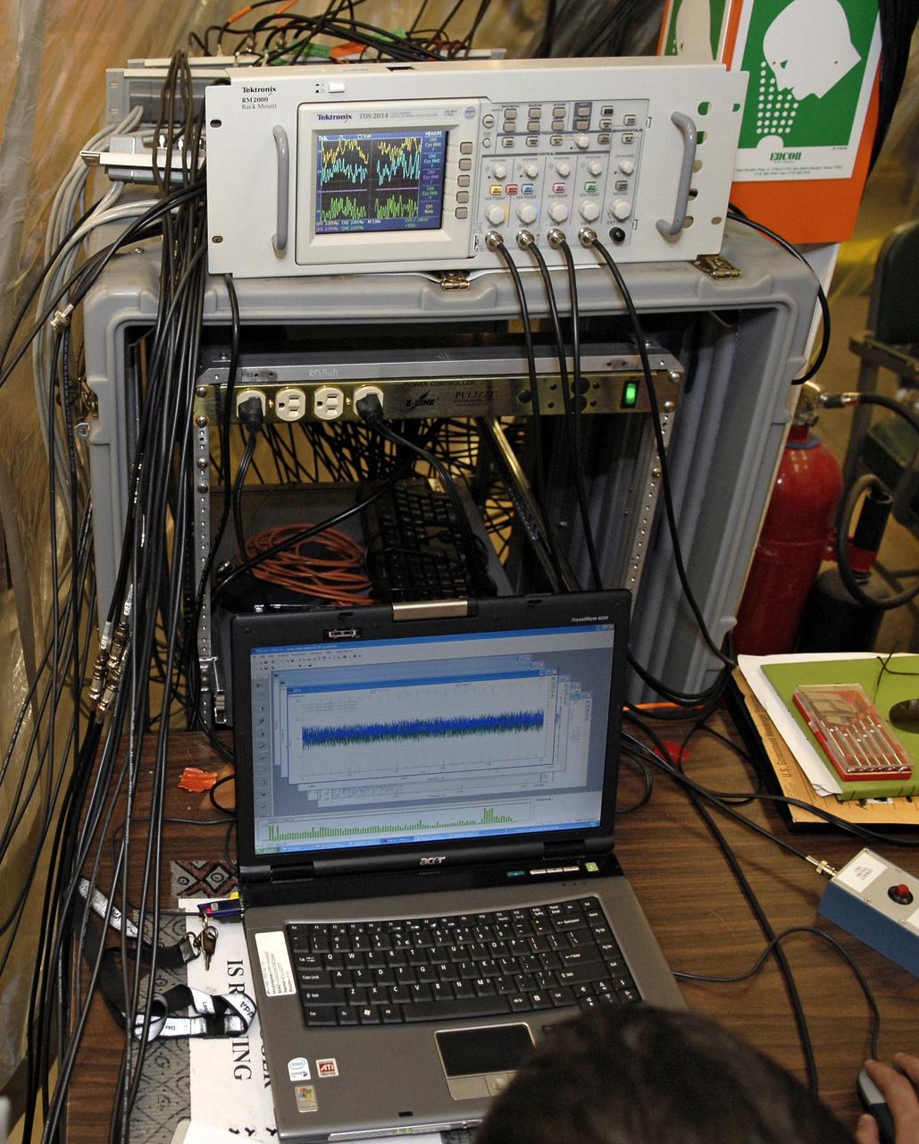
CAPE CANAVERAL, Fla. – In the Vehicle Assembly Building's High Bay 4 at NASA's Kennedy Space Center in Florida, equipment collects data from a sway test being conducted on the Ares I-X launch vehicle. The test is simulating conditions the rocket could experience during rollout to Launch Pad 39B, wind conditions at the pad and first-stage ignition. During the test, vibrations are mechanically induced into the rocket by four hydraulic shakers and a sway is manually introduced for lateral motion to measure the vehicle's response. A total of 44 accelerometers are installed on the flight test vehicle that required more than 27,000 feet of cable. Part of the Constellation Program, the Ares I-X is the test vehicle for the Ares I, which is the essential core of a space transportation system that eventually will carry crewed missions back to the moon, on to Mars and out into the solar system . The Ares I-X flight test is targeted for Oct. 31. Photo credit: NASA/Kim Shiflett
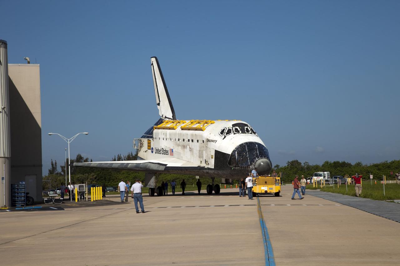
CAPE CANAVERAL, Fla. -- At NASA's Kennedy Space Center in Florida, space shuttle Discovery is towed from Orbiter Processing Facility-2, or OPF-2, to the Vehicle Assembly Building, or VAB. Railings, called strongbacks, are installed along Discovery's payload bay doors to assist with opening and closing of the doors when the shuttle's hydraulic system is not operational and support the doors while they are open. Discovery will be stored inside the VAB for approximately one month while shuttle Atlantis undergoes processing in OPF-2 following its final mission, STS-135. Discovery flew its 39th and final mission, STS-133, in February and March 2011, and currently is being prepared for public display at the Smithsonian's National Air and Space Museum Steven F. Udvar-Hazy Center in Virginia. For more information about Discovery's Transition and Retirement, visit www.nasa.gov/mission_pages/shuttle/launch/discovery_rss_collection_archive_1.html. Photo credit: NASA/Frankie Martin
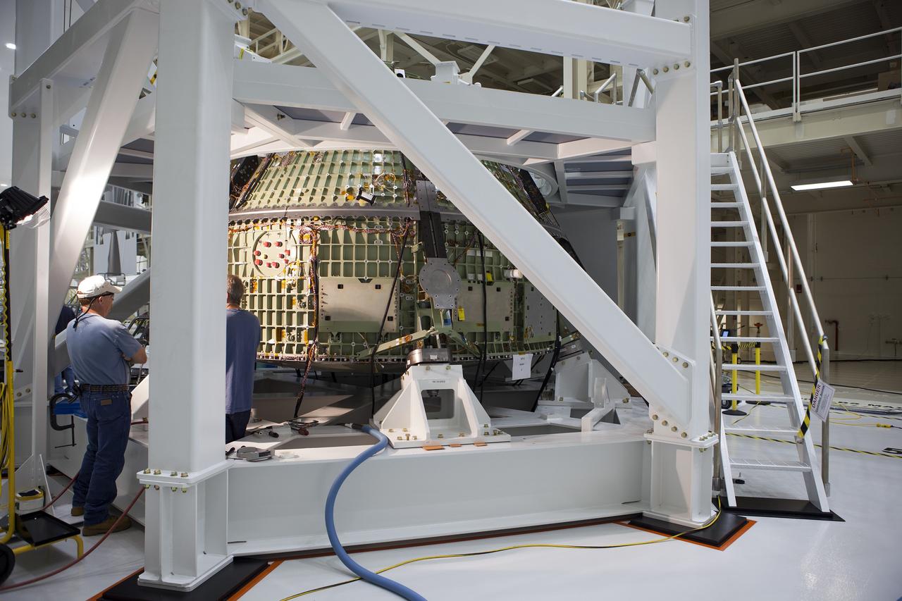
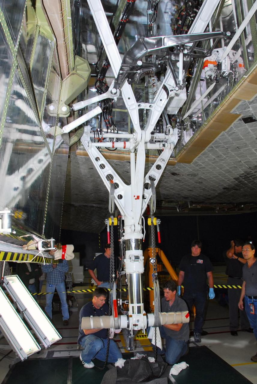
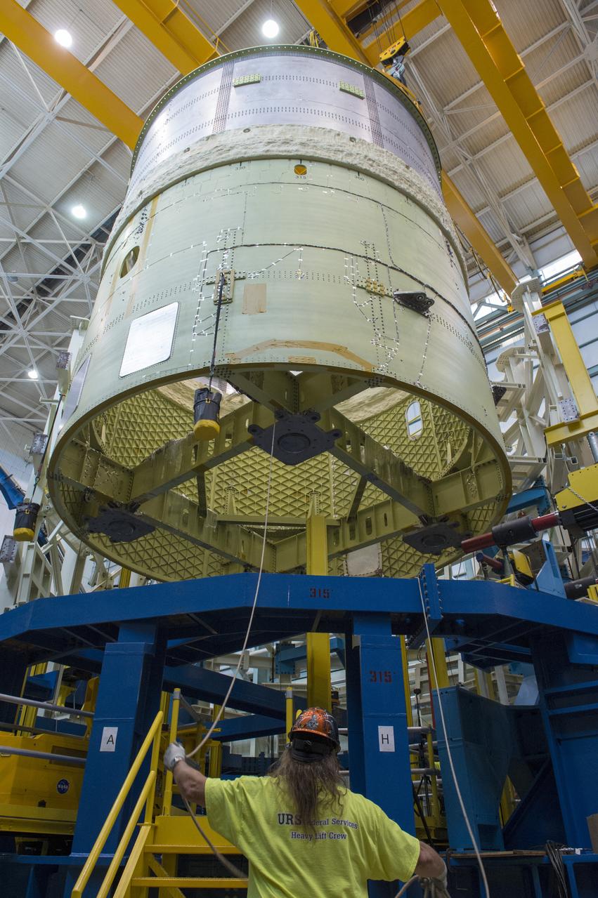
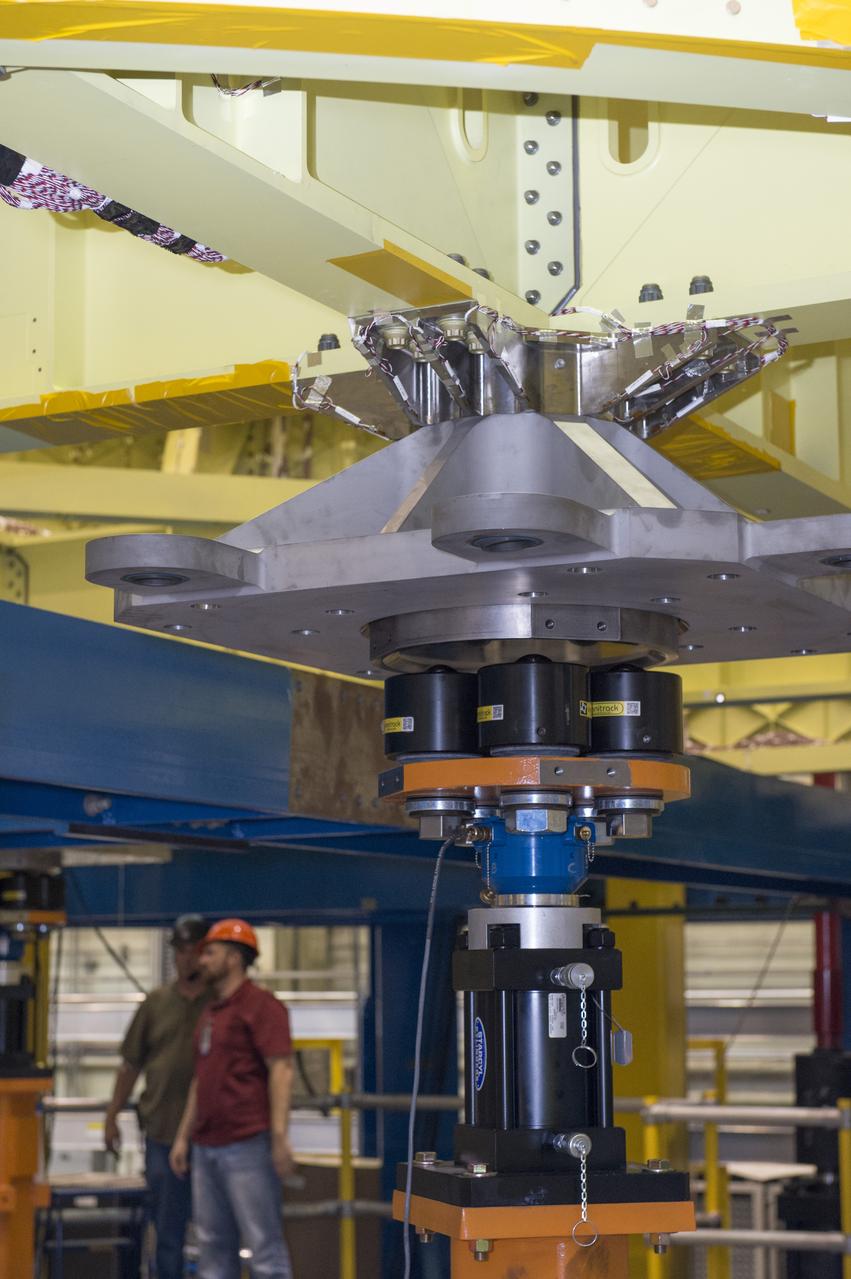
CAPE CANAVERAL, Fla. -- Inside the Operations and Checkout Building high bay at NASA’s Kennedy Space Center in Florida, technicians place a hydraulic actuator in the test stand for the Orion crew module. Lockheed Martin Space Systems and NASA engineers are preparing Orion for a series of static load tests that simulate the massive loads the spacecraft would experience during its mission. Orion is the exploration spacecraft designed to carry crews to space beyond low Earth orbit. It will provide emergency abort capability, sustain the crew during the space travel and provide safe re-entry from deep space return velocities. Orion’s first unpiloted test flight, Exploration Flight Test 1, is scheduled to launch in 2014 atop a Delta IV rocket. A second uncrewed flight test is scheduled for 2017 on NASA’s Space Launch System rocket. For more information, visit http://www.nasa.gov/orion. Photo credit: NASA/Gary Thompson
CAPE CANAVERAL, Fla. – In the Vehicle Assembly Building's High Bay 4 at NASA's Kennedy Space Center in Florida, equipment is set up to conduct a sway test on the Ares I-X launch vehicle. The test is simulating conditions the rocket could experience during rollout to Launch Pad 39B, wind conditions at the pad and first-stage ignition. During the test, vibrations are mechanically induced into the rocket by four hydraulic shakers and a sway is manually introduced for lateral motion to measure the vehicle's response. A total of 44 accelerometers are installed on the flight test vehicle that required more than 27,000 feet of cable. Part of the Constellation Program, the Ares I-X is the test vehicle for the Ares I, which is the essential core of a space transportation system that eventually will carry crewed missions back to the moon, on to Mars and out into the solar system . The Ares I-X flight test is targeted for Oct. 31. Photo credit: NASA/Kim Shiflett
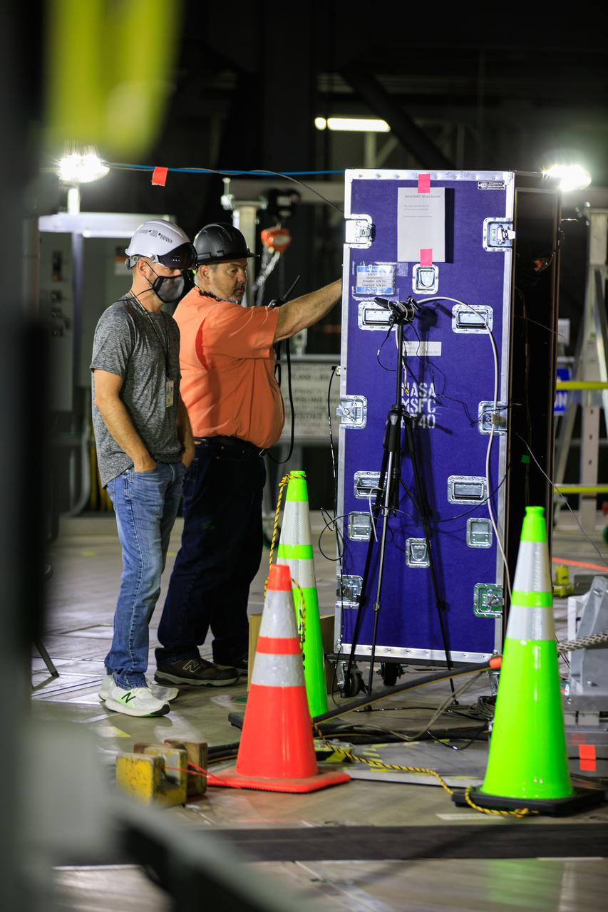
Artemis teams members perform the integrated modal test of the Space Launch System and mobile launcher in High Bay 3 of the Vehicle Assembly Building at NASA’s Kennedy Space Center in Florida on Sept. 24, 2021. The tests will help determine the natural frequencies of the recently stacked rocket before launch of the Artemis I mission. The data also will be used to help steer the rocket during flight. To identify the rocket’s natural frequencies, the team placed about 300 sensors on it and the mobile launcher to detect, record, and transmit the information, along with hydraulic shakers attached to seven locations on the rocket. Artemis I will be the first integrated test of the SLS and Orion spacecraft. In later missions, NASA will land the first woman and the first person of color on the surface of the Moon, paving the way for a long-term lunar presence and serving as a steppingstone on the way to Mars.
NASA engineers install test hardware for the agency's new heavy lift rocket, the Space Launch System, into a newly constructed 50-foot structural test stand at NASA's Marshall Space Flight Center. In the stand, hydraulic cylinders will be electronically controlled to push, pull, twist and bend the test article with millions of pounds of force. Engineers will record and analyze over 3,000 channels of data for each test case to verify the capabilities of the engine section and validate that the design and analysis models accurately predict the amount of loads the core stage can withstand during launch and ascent. The engine section, recently delivered via NASA's barge Pegasus from NASA's Michoud Assembly Facility, is the first of four core stage structural test articles scheduled to be delivered to Marshall for testing. The engine section, located at the bottom of SLS's massive core stage, will house the rocket's four RS-25 engines and be an attachment point for the two solid rocket boosters.
This collection of photos shows the steps NASA engineers took to lift the final structural test article for NASA’s Space Launch System (SLS) core stage into Test Stand 4697 at NASA’s Marshall Space Flight Center in Huntsville, Alabama, July 10, 2019. The liquid oxygen (LOX) tank is one of two propellant tanks in the rocket’s massive core stage that will produce more than 2 million pounds of thrust to help launch Artemis 1, the first flight of NASA’s Orion spacecraft and SLS, to the Moon. The nearly 70-foot-long liquid oxygen tank structural test article was manufactured at NASA’s Michoud Assembly Facility in New Orleans and delivered by NASA’s barge Pegasus to Marshall. Once bolted into the test stand, dozens of hydraulic cylinders will push and pull the tank, subjecting it to the same stresses and forces it will endure during liftoff and flight, to verify it is fit for flight.
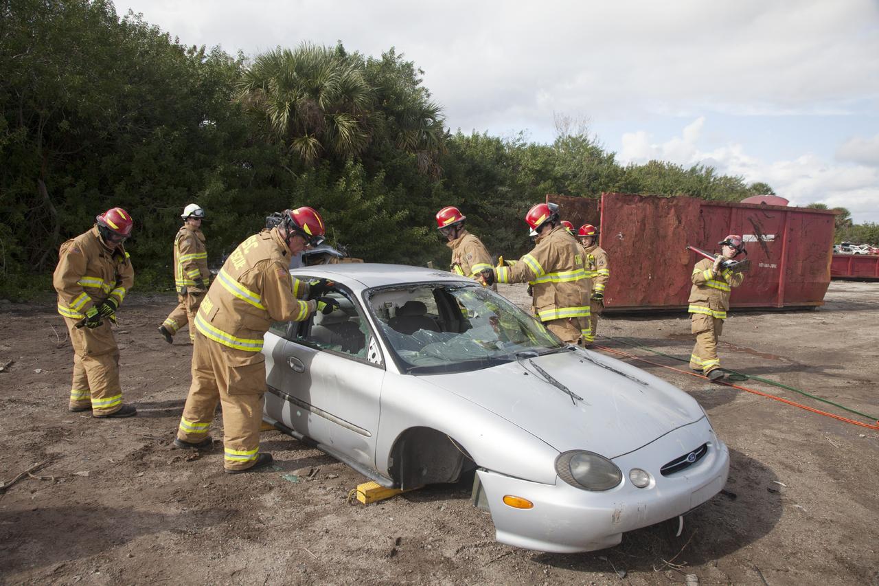
CAPE CANAVERAL, Fla. – Special Rescue Operations firefighters with NASA Fire Rescue Services in the Protective Services Office at NASA’s Kennedy Space Center in Florida practice vehicle extrication training at an auto salvage yard near the center. Stabilizing blocks have been placed underneath the car. Firefighters practiced knocking out the windshield and windows with axes and other tools. They will use the Jaws of Life on the vehicle to simulate the rescue of a trapped and injured person. Other rescue equipment includes a hydraulic cutting tool that is used to remove the roof of a car. Kennedy’s firefighters recently achieved Pro Board Certification in aerial fire truck operations. With the completion of vehicle extrication and Jaws of Life training, the Protective Services Office is one step closer to achieving certification in vehicle machinery extrication. Kennedy’s firefighters are with G4S Government Solutions Inc., on the Kennedy Protective Services Contract. Photo credit: NASA/Daniel Casper
CAPE CANAVERAL, Fla. -- Crawler-transporter 1 continues its trek from the crawler transporter maintenance facility to Launch Pad 39A at NASA’s Kennedy Space Center in Florida. New jacking, equalizing and leveling, or JEL, hydraulic cylinders were installed on CT-1 and are being tested for increased load carrying capacity and reliability. The Ground Systems Development and Operations Program at Kennedy continues to upgrade the crawler-transporter as part of its general maintenance. CT-1 could be available to carry a variety of launch vehicles to the launch pad. Two crawler-transporters were used to carry the mobile launcher platform and space shuttle to Launch Complex 39 for space shuttle launches for 30 years. Photo credit: NASA/Daniel Casper
NASA engineers install test hardware for the agency's new heavy lift rocket, the Space Launch System, into a newly constructed 50-foot structural test stand at NASA's Marshall Space Flight Center. In the stand, hydraulic cylinders will be electronically controlled to push, pull, twist and bend the test article with millions of pounds of force. Engineers will record and analyze over 3,000 channels of data for each test case to verify the capabilities of the engine section and validate that the design and analysis models accurately predict the amount of loads the core stage can withstand during launch and ascent. The engine section, recently delivered via NASA's barge Pegasus from NASA's Michoud Assembly Facility, is the first of four core stage structural test articles scheduled to be delivered to Marshall for testing. The engine section, located at the bottom of SLS's massive core stage, will house the rocket's four RS-25 engines and be an attachment point for the two solid rocket boosters.

CAPE CANAVERAL, Fla. -- At NASA's Kennedy Space Center in Florida, space shuttle Discovery rolls along the towway from Orbiter Processing Facility-2, or OPF-2, to the Vehicle Assembly Building, or VAB. Railings, called strongbacks, are installed along Discovery's payload bay doors to assist with opening and closing of the doors when the shuttle's hydraulic system is not operational and support the doors while they are open. Discovery will be stored inside the VAB for approximately one month while shuttle Atlantis undergoes processing in OPF-2 following its final mission, STS-135. Discovery flew its 39th and final mission, STS-133, in February and March 2011, and currently is being prepared for public display at the Smithsonian's National Air and Space Museum Steven F. Udvar-Hazy Center in Virginia. For more information about Discovery's Transition and Retirement, visit www.nasa.gov/mission_pages/shuttle/launch/discovery_rss_collection_archive_1.html. Photo credit: NASA/Frankie Martin
KENNEDY SPACE CENTER, FLA. -- This photo looks inside space shuttle Discovery's right main-gear strut where a leaking seal has been found. United Space Alliance and B.F. Goodrich technicians will replace the seal. The struts act as shock absorbers during the shuttle's landing. Engineers determined the observed leak of hydraulic fluid in the main landing gear strut exceeded specification and could not be reduced to an acceptable rate. Removing the strut and replacing seals require disconnecting and replacing the brakes and tires, disconnecting and reconnecting instruments and other requirements to allow access to the strut. Discovery had been scheduled to roll over Sept. 19 from its processing hangar to the Vehicle Assembly Building. A new rollover date will be set after technicians determine how long replacing the seal will take. Photo credit: NASA/George Shelton
NASA engineers install test hardware for the agency's new heavy lift rocket, the Space Launch System, into a newly constructed 50-foot structural test stand at NASA's Marshall Space Flight Center. In the stand, hydraulic cylinders will be electronically controlled to push, pull, twist and bend the test article with millions of pounds of force. Engineers will record and analyze over 3,000 channels of data for each test case to verify the capabilities of the engine section and validate that the design and analysis models accurately predict the amount of loads the core stage can withstand during launch and ascent. The engine section, recently delivered via NASA's barge Pegasus from NASA's Michoud Assembly Facility, is the first of four core stage structural test articles scheduled to be delivered to Marshall for testing. The engine section, located at the bottom of SLS's massive core stage, will house the rocket's four RS-25 engines and be an attachment point for the two solid rocket boosters.

KENNEDY SPACE CENTER, FLA. -- This photo reveals the area of a seal on space shuttle Discovery's right main-gear strut that was determined to be leaking. United Space Alliance and B.F. Goodrich technicians are replacing the seal. The struts act as shock absorbers during the shuttle's landing. Engineers determined the observed leak of hydraulic fluid in the main landing gear strut exceeded specification and could not be reduced to an acceptable rate. Removing the strut and replacing seals require disconnecting and replacing the brakes and tires, disconnecting and reconnecting instruments and other requirements to allow access to the strut. Discovery had been scheduled to roll over Sept. 19 from its processing hangar to the Vehicle Assembly Building. A new rollover date will be set after technicians determine how long replacing the seal will take. Photo credit: NASA/George Shelton
NASA engineers install test hardware for the agency's new heavy lift rocket, the Space Launch System, into a newly constructed 50-foot structural test stand at NASA's Marshall Space Flight Center. In the stand, hydraulic cylinders will be electronically controlled to push, pull, twist and bend the test article with millions of pounds of force. Engineers will record and analyze over 3,000 channels of data for each test case to verify the capabilities of the engine section and validate that the design and analysis models accurately predict the amount of loads the core stage can withstand during launch and ascent. The engine section, recently delivered via NASA's barge Pegasus from NASA's Michoud Assembly Facility, is the first of four core stage structural test articles scheduled to be delivered to Marshall for testing. The engine section, located at the bottom of SLS's massive core stage, will house the rocket's four RS-25 engines and be an attachment point for the two solid rocket boosters.
CAPE CANAVERAL, Fla. -- Ground support equipment technicians monitor the progress as crawler-transporter 1 continues its trek along the crawlerway to Launch Pad 39A at NASA’s Kennedy Space Center in Florida. New jacking, equalizing and leveling, or JEL, hydraulic cylinders were installed on CT-1 and are being tested for increased load carrying capacity and reliability. The Ground Systems Development and Operations Program at Kennedy continues to upgrade the crawler-transporter as part of its general maintenance. CT-1 could be available to carry a variety of launch vehicles to the launch pad. Two crawler-transporters were used to carry the mobile launcher platform and space shuttle to Launch Complex 39 for space shuttle launches for 30 years. Photo credit: NASA/Daniel Casper

NASA engineers install test hardware for the agency's new heavy lift rocket, the Space Launch System, into a newly constructed 50-foot structural test stand at NASA's Marshall Space Flight Center. In the stand, hydraulic cylinders will be electronically controlled to push, pull, twist and bend the test article with millions of pounds of force. Engineers will record and analyze over 3,000 channels of data for each test case to verify the capabilities of the engine section and validate that the design and analysis models accurately predict the amount of loads the core stage can withstand during launch and ascent. The engine section, recently delivered via NASA's barge Pegasus from NASA's Michoud Assembly Facility, is the first of four core stage structural test articles scheduled to be delivered to Marshall for testing. The engine section, located at the bottom of SLS's massive core stage, will house the rocket's four RS-25 engines and be an attachment point for the two solid rocket boosters.
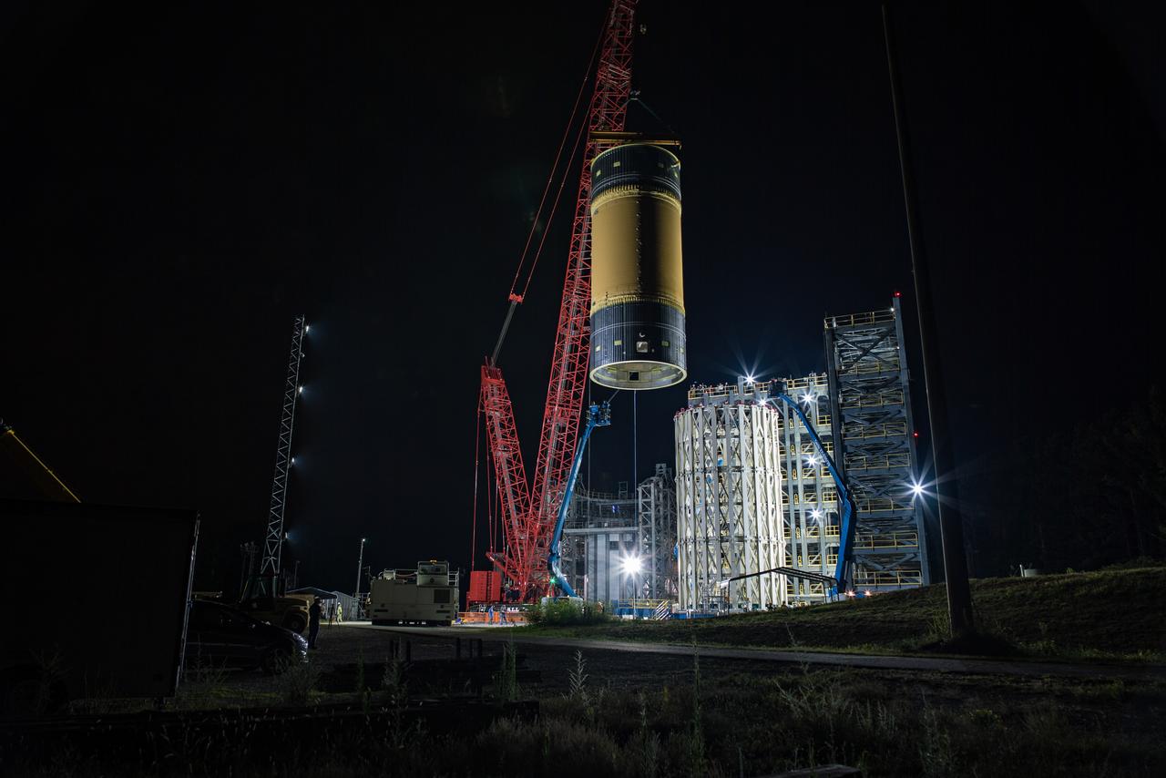
This collection of photos shows the steps NASA engineers took to lift the final structural test article for NASA’s Space Launch System (SLS) core stage into Test Stand 4697 at NASA’s Marshall Space Flight Center in Huntsville, Alabama, July 10, 2019. The liquid oxygen (LOX) tank is one of two propellant tanks in the rocket’s massive core stage that will produce more than 2 million pounds of thrust to help launch Artemis 1, the first flight of NASA’s Orion spacecraft and SLS, to the Moon. The nearly 70-foot-long liquid oxygen tank structural test article was manufactured at NASA’s Michoud Assembly Facility in New Orleans and delivered by NASA’s barge Pegasus to Marshall. Once bolted into the test stand, dozens of hydraulic cylinders will push and pull the tank, subjecting it to the same stresses and forces it will endure during liftoff and flight, to verify it is fit for flight.