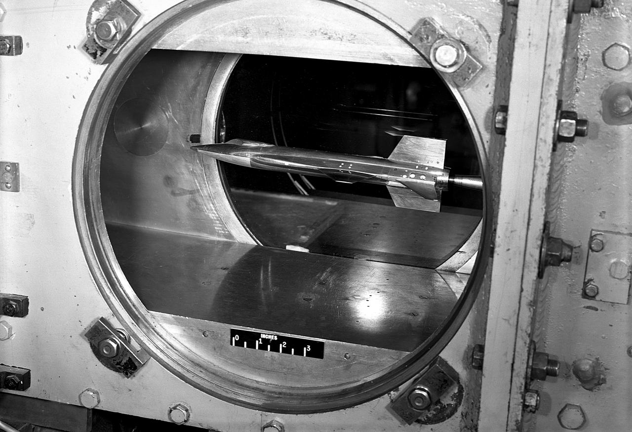
Scale-model of final X-15 configuration, mounted for testing in the Langley 11-Inch Hypersonic Tunnel.
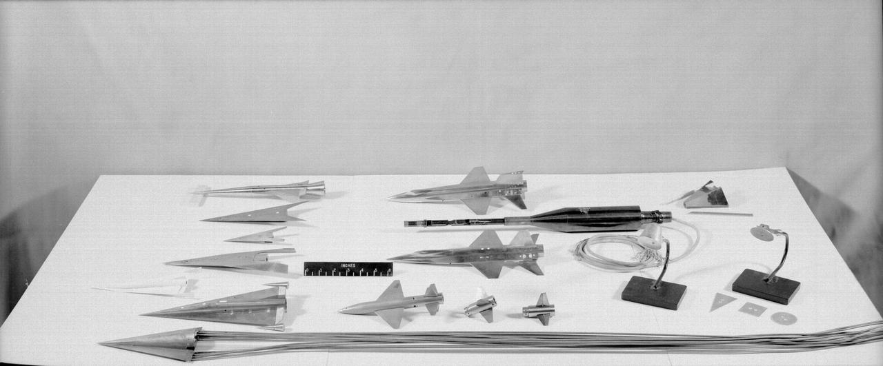
11-Inch Hypersonic Tunnel: various models tested in the tunnel.
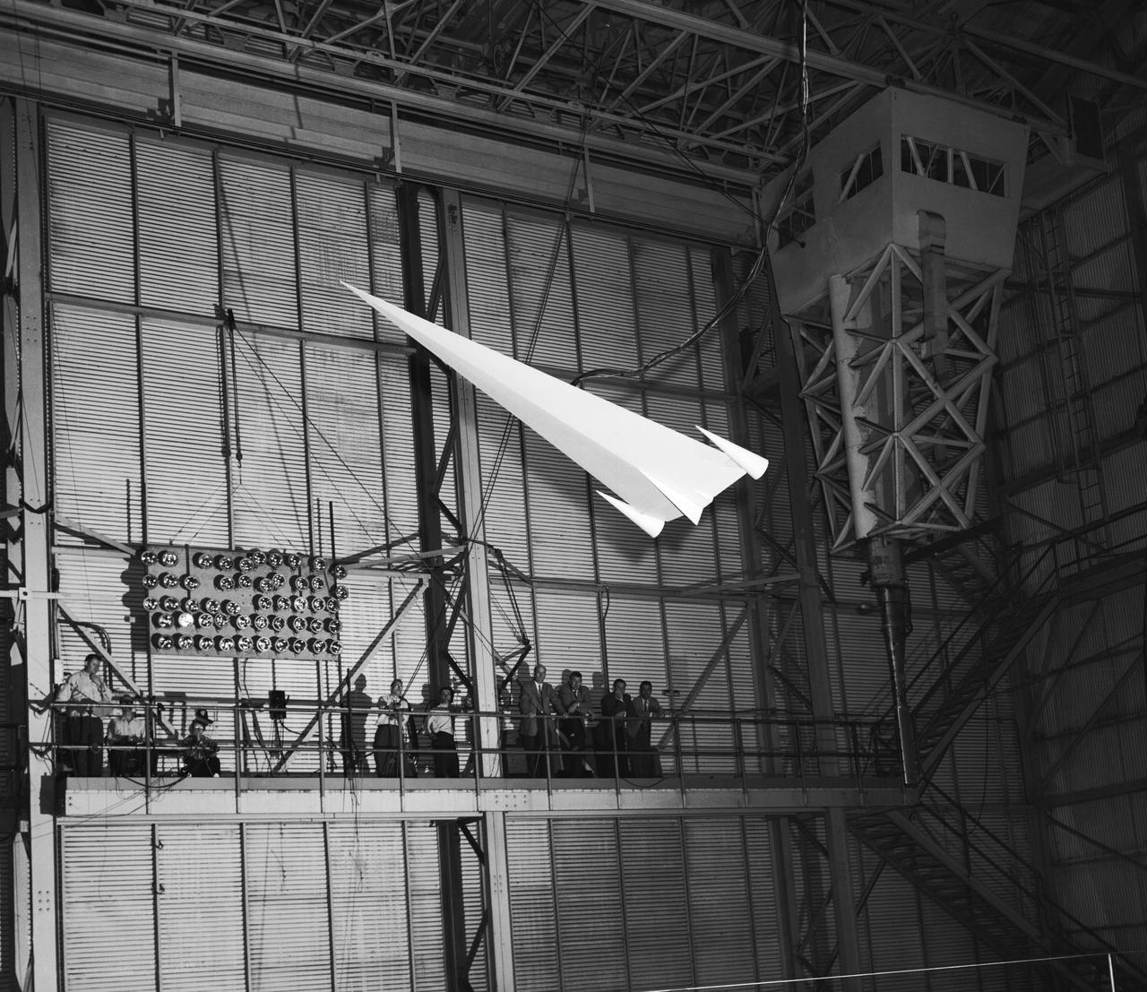
L57-1439 A model based on Langley s concept of a hypersonic glider was test flown on an umbilical cord inside the Full Scale Tunnel in 1957. Photograph published in Engineer in Charge: A History of the Langley Aeronautical Laboratory, 1917-1958 by James R. Hansen. Page 374.
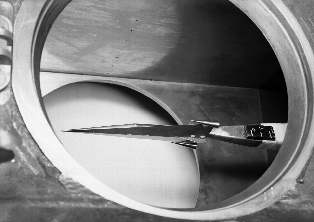
Hypersonic Boost Glider in 11 Inch Hypersonic Tunnel L57-1681 In 1957 Langley tested its HYWARDS design in the 11 Inch Hypersonic Tunnel. Photograph published in Engineer in Charge: A History of the Langley Aeronautical Laboratory, 1917-1958 by James R. Hansen. Page 369.

Hypersonic Tunnel Facility
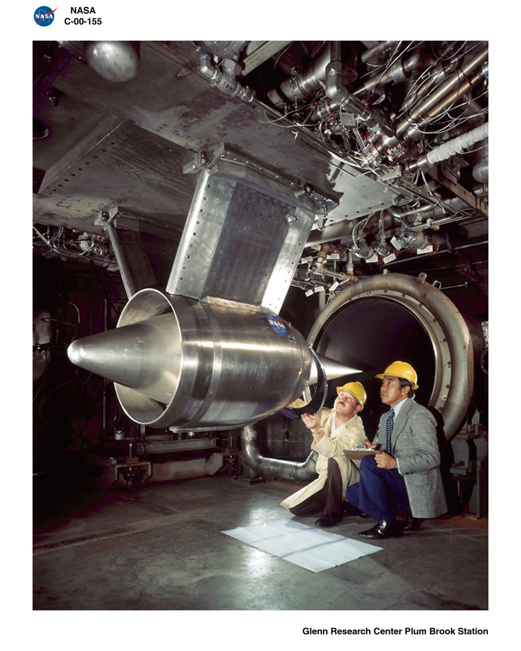
GARRETT ENGINE IN HYPERSONIC TUNNEL FACILITY HTF AT NASA PLUM BROOK STATION
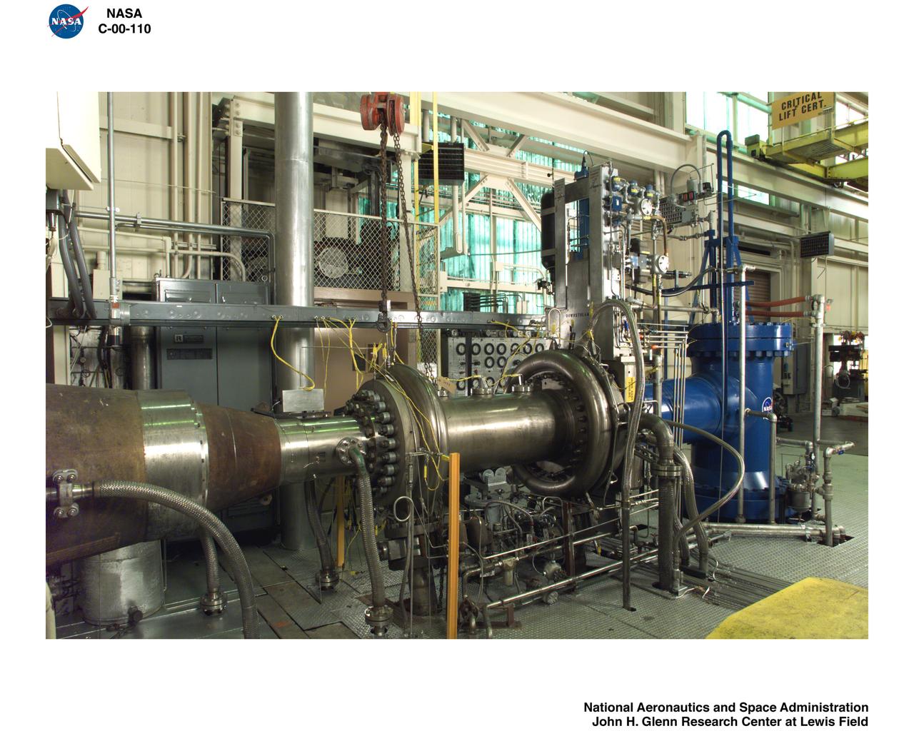
HYPERSONIC TUNNEL FACILITY HTF AT NASA PLUM BROOK STATION
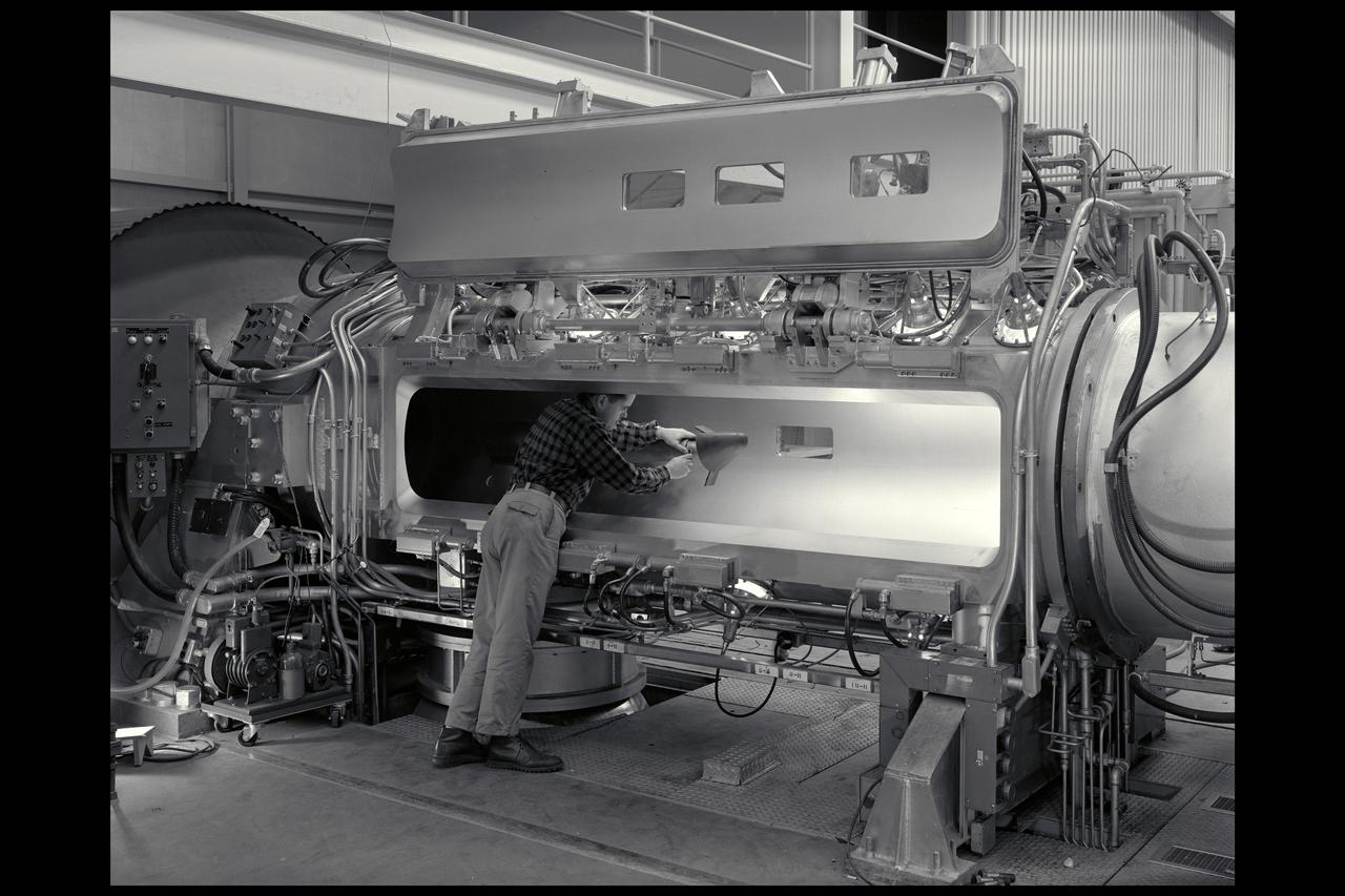
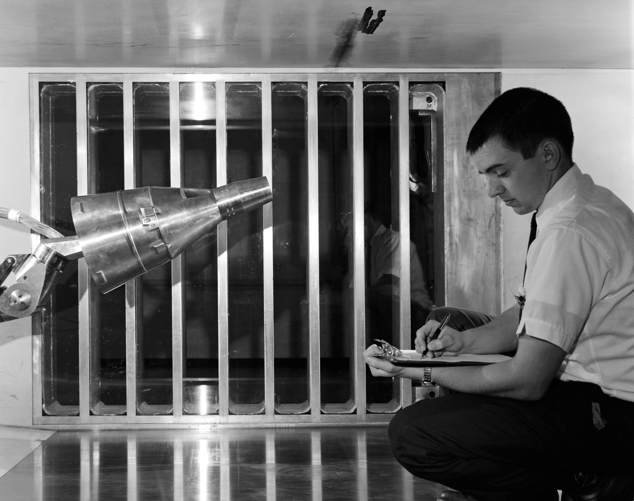
M-1 model of reentry body in 3.5ft Hypersonic Wind Tunnel throat

Space Shuttle Orbitor model 140 A/B-OA87 testing in the 3.5ft Hypersonic Wind Tunnel

Research, Science, and Engineering Services (RSES) intern tour of the 8ft high temperature hypersonic wind tunnel (8ft HTT/B1265)
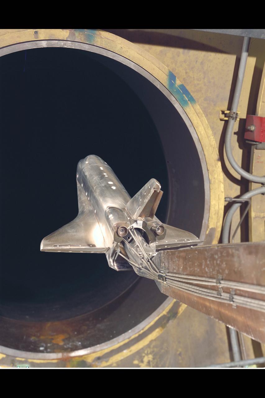
Space Shuttle Orbitor model 140 A/B-OA87 testing in the 3.5ft Hypersonic Wind Tunnel
A chambered and twisted wing-body. Arrow wing hypersonic model tested in the 6x6 foot wind tunnel at the NASA Ames Research Center.
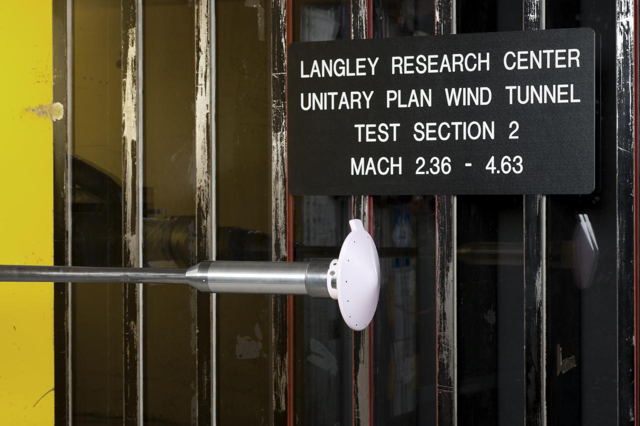
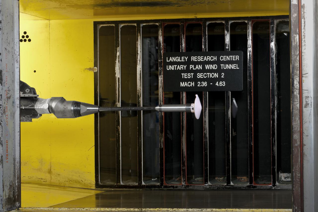
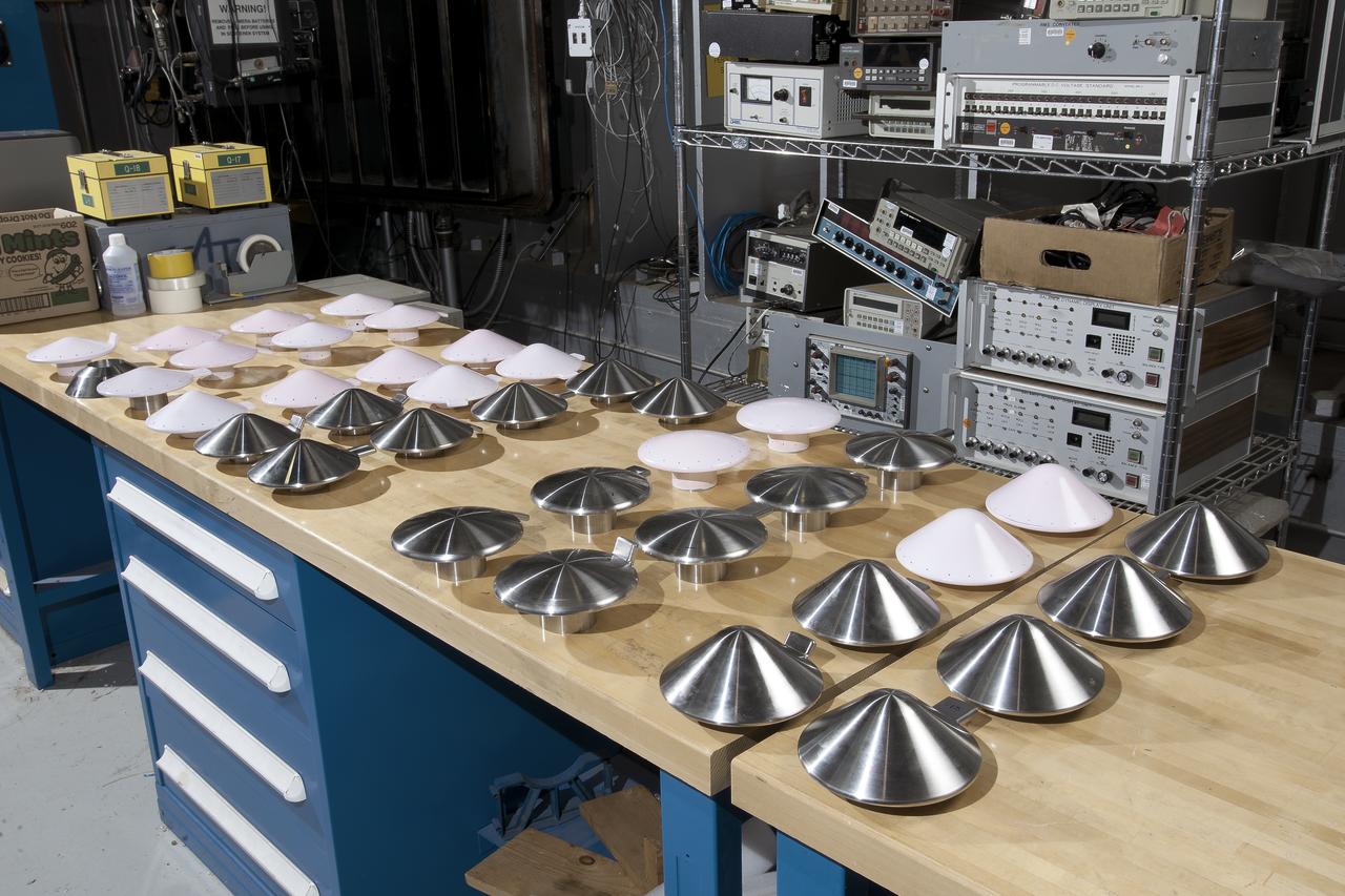
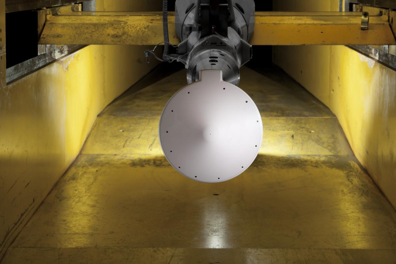
Test 1875 in Unitary Plan Wind Tunnel (UPWT) HIADS TTPM: Trim Tab study on various cone angled heat shields (TTPM) Technology Technical Performance Metric (HIADS) Hypersonic inflatable aerodynamic decelerators
Test 1875 in Unitary Plan Wind Tunnel (UPWT) HIADS TTPM: Trim Tab study on various cone angled heat shields (TTPM) Technology Technical Performance Metric (HIADS) Hypersonic inflatable aerodynamic decelerators
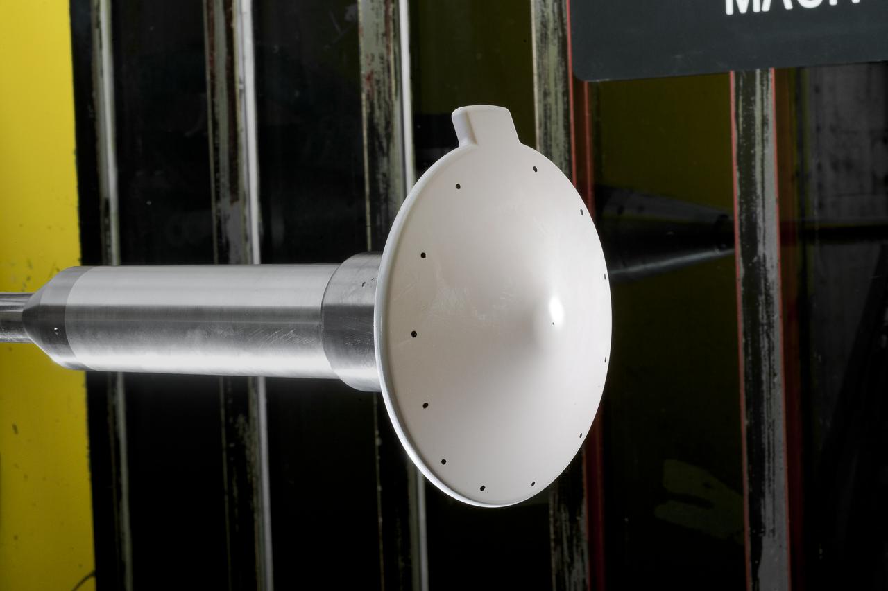
Test 1875 in Unitary Plan Wind Tunnel (UPWT) HIADS TTPM: Trim Tab study on various cone angled heat shields (TTPM) Technology Technical Performance Metric (HIADS) Hypersonic inflatable aerodynamic decelerators
Test 1875 in Unitary Plan Wind Tunnel (UPWT) HIADS TTPM: Trim Tab study on various cone angled heat shields (TTPM) Technology Technical Performance Metric (HIADS) Hypersonic inflatable aerodynamic decelerators
Test 1875 in Unitary Plan Wind Tunnel (UPWT) HIADS TTPM: Trim Tab study on various cone angled heat shields (TTPM) Technology Technical Performance Metric (HIADS) Hypersonic inflatable aerodynamic decelerators
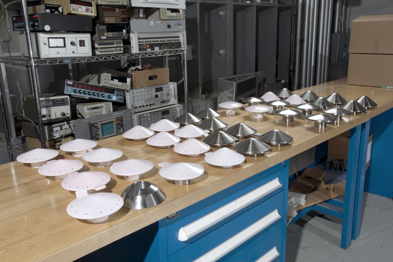
Test 1875 in Unitary Plan Wind Tunnel (UPWT) HIADS TTPM: Trim Tab study on various cone angled heat shields (TTPM) Technology Technical Performance Metric (HIADS) Hypersonic inflatable aerodynamic decelerators
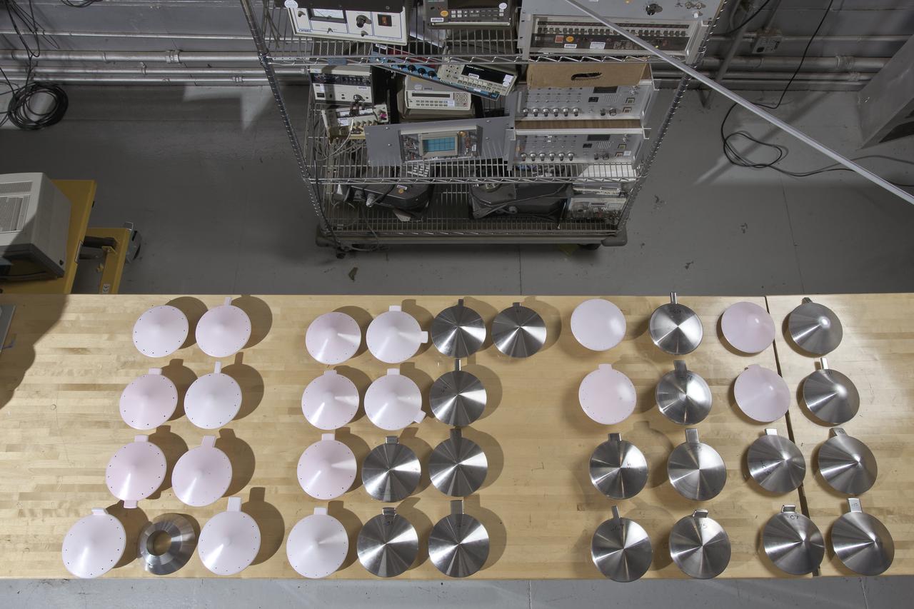
Test 1875 in Unitary Plan Wind Tunnel (UPWT) HIADS TTPM: Trim Tab study on various cone angled heat shields (TTPM) Technology Technical Performance Metric (HIADS) Hypersonic inflatable aerodynamic decelerators
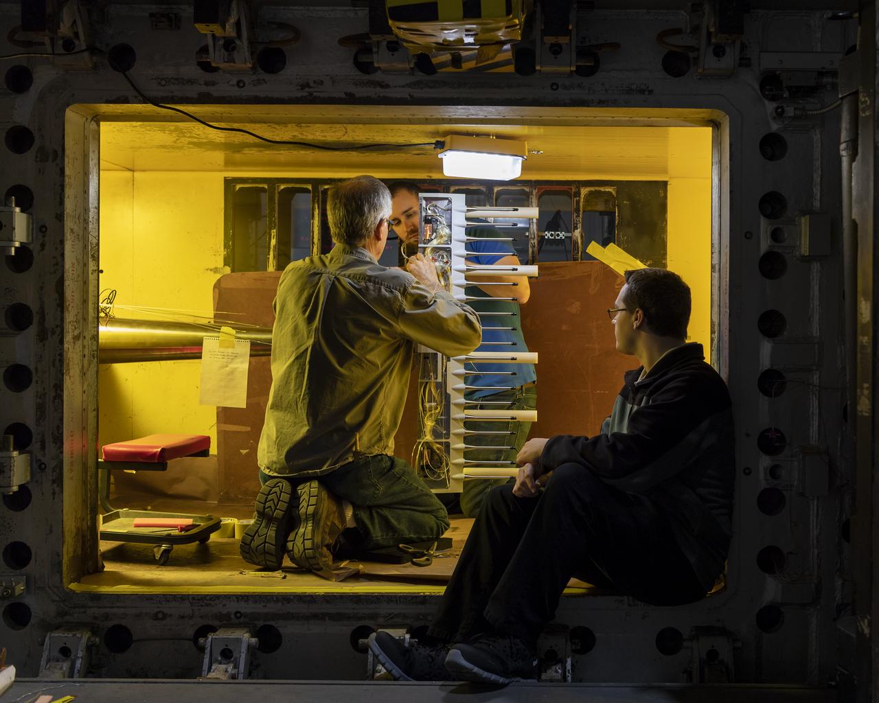
LaRC OCIO's Media Solutions Branch Photographer Harlen Capen photographed the installation of a new flow survey rake for the supersonic Unitary Plan Wind Tunnel (UPWT). The hardware – shown installed in the 4-foot, high-Mach-number Test Section 2 with a coating of Pressure Sensitive Paint – consists of a purpose-built sting, rake body, and two different types of pressure measurement probes. The survey rake will be used to characterize the flow in the test section in support of the "CFD Central Flight Dynamics as a Surrogate for High Speed Supersonic Tests" People in the photo L to R are, Ricky L. Hall, Jacobs Technology, Inc.,Supersonic/Hypersonic Testing Branch - Group A, Alexander (Alex) Moore Jacobs Technology, Inc, Supersonic/Hypersonic Testing Branch and Mathew A. (Alec) Reed, Jacobs Technology, In. NASA photographer Harlen Capen won First Place in the NASA's 2019 Still Photographer of the Year competition in the "People" category with this image.
Gemini capsule being tested in Unitary Plan Wind Tunnel.
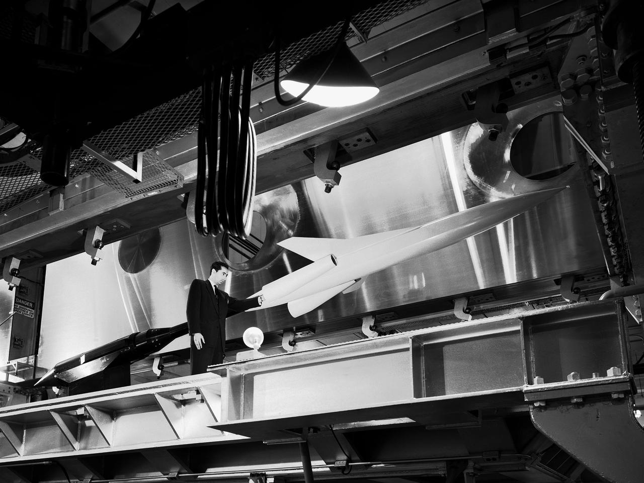
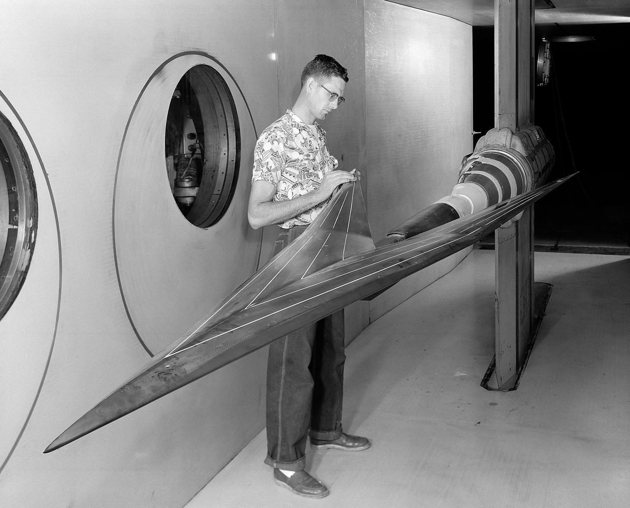
A researcher examines a model being installed in the test section of the 10- by 10-Foot Supersonic Wind Tunnel during the 1957 Inspection of the National Advisory Committee for Aeronautics (NACA) Lewis Flight Propulsion Laboratory. The NACA held its annual Inspection at one of its three research laboratories. Representatives from the military, aeronautical industry, universities, and the press were invited to the laboratory to be briefed on the NACA’s latest research efforts and tour the state- of- the- art test facilities. Over 1700 people visited the NACA Lewis in Cleveland, Ohio during the October 7 - 10, 1957 Inspection. NACA researchers Leonard Obery, seen here, James Connors, Leonard, Stitt, David Bowditch gave presentations on high Mach number turbojets at the 10- by 10 tunnel. It had been only 15 years since a jet aircraft had first flown in the US. Since then the sound barrier had been broken and speeds of Mach 2.5 had been achieved. In the late 1950s NACA researchers sought to create an engine that could achieve Mach 4. This type of engine would require an extremely long inlet and nozzle which would have to be capable of adjusting their diameter for different speeds. A Mach 4 engine would require new composite materials to withstand the severe conditions, modified airframes to hold the longer engines, and high temperature seals and lubricants. The 10- by 10-foot tunnel, which had only been in operation for a year and a half, would play a critical role in these studies. NACA researchers at other facilities discussed high energy aircraft fuels and rocket propellants, aircraft noise reduction, hypersonic flight, nuclear propulsion, and high temperature materials.
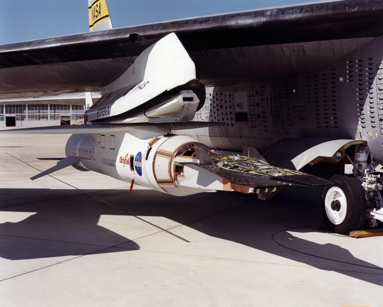
The first of three X-43A hypersonic research aircraft and its modified Pegasus® booster rocket recently underwent combined systems testing while mounted to NASA's NB-52B carrier aircraft at the Dryden Flight Research Center, Edwards, California. The combined systems test was one of the last major milestones in the Hyper-X research program before the first X-43A flight. One of the major goals of the Hyper-X program is flight validation of airframe-integrated, air-breathing propulsion system, which so far have only been tested in ground facilities, such as wind tunnels. The X-43A flights will be the first actual flight tests of an aircraft powered by a revolutionary supersonic-combustion ramjet ("scramjet") engine capable of operating at hypersonic speeds above Mach 5 (five times the speed of sound). The X-43A design uses the underbody of the aircraft to form critical elements of the engine. The forebody shape helps compress the intake airflow, while the aft section acts as a nozzle to direct thrust. The 12-foot, unpiloted research vehicle was developed and built by MicroCraft Inc., Tullahoma, Tenn., under NASA contract. The booster, built by Orbital Sciences Corp., Dulles, Va., will accelerate the X-43A after the X-43A/booster "stack" is air-launched from NASA's venerable NB-52 mothership. The X-43A will separate from the rocket at a predetermined altitude and speed and fly a pre-programmed trajectory, conducting aerodynamic and propulsion experiments until it descends into the Pacific Ocean. Three research flights are planned, two at Mach 7 and one at Mach 10.