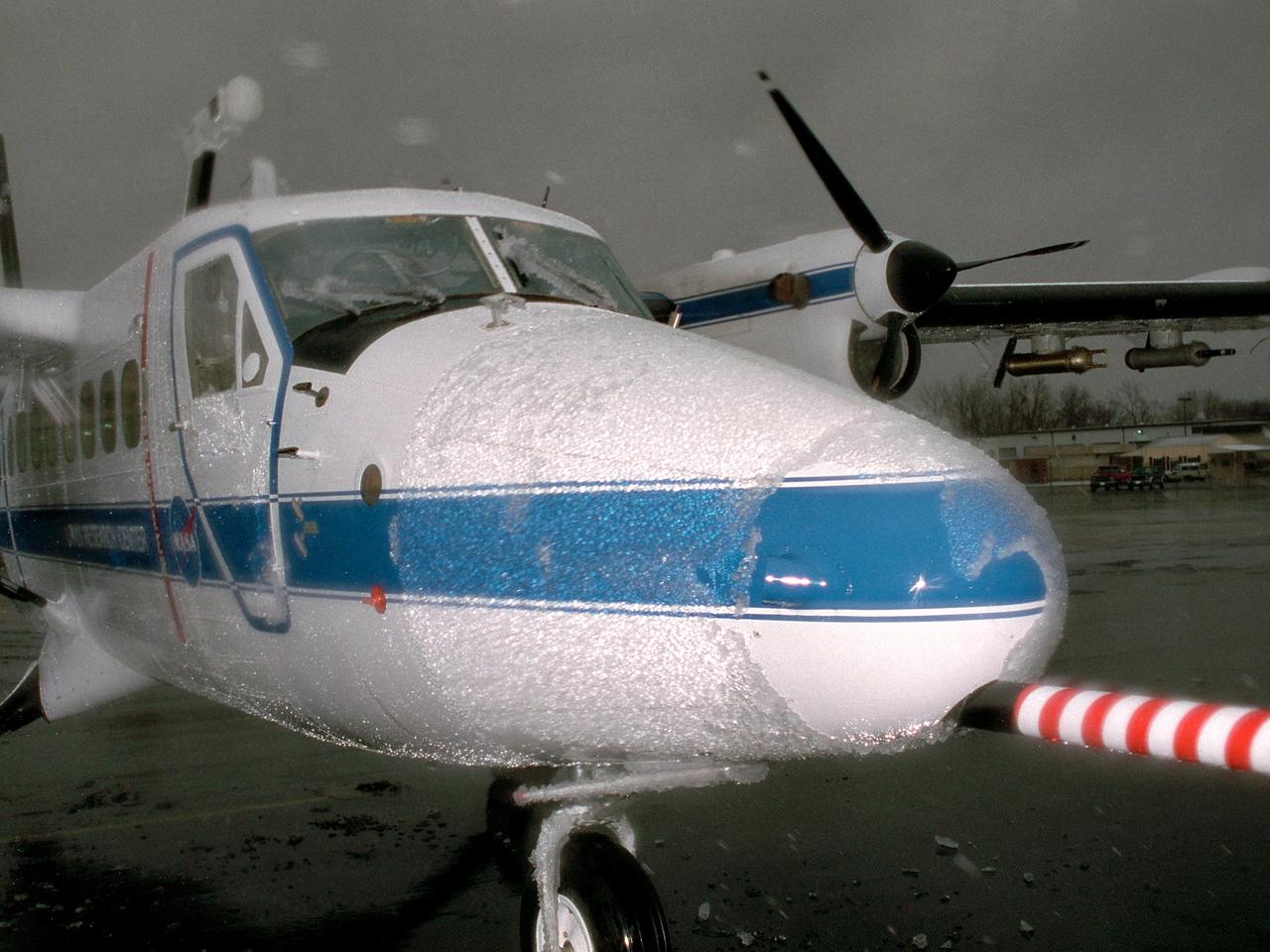
Supercooled Large Droplet (SLD) icing encounter in the Twin Otter icing research aircraft.

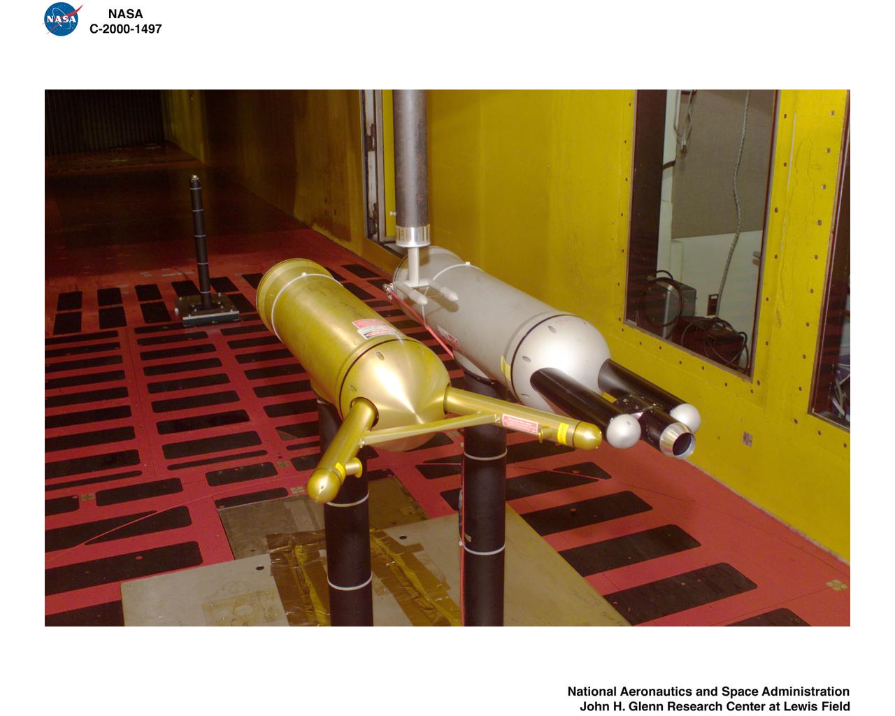
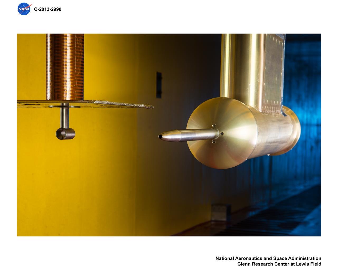
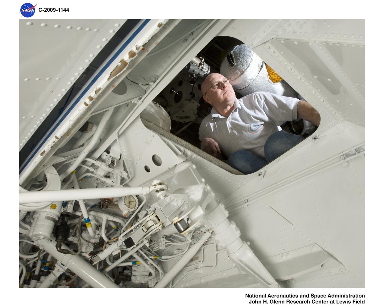
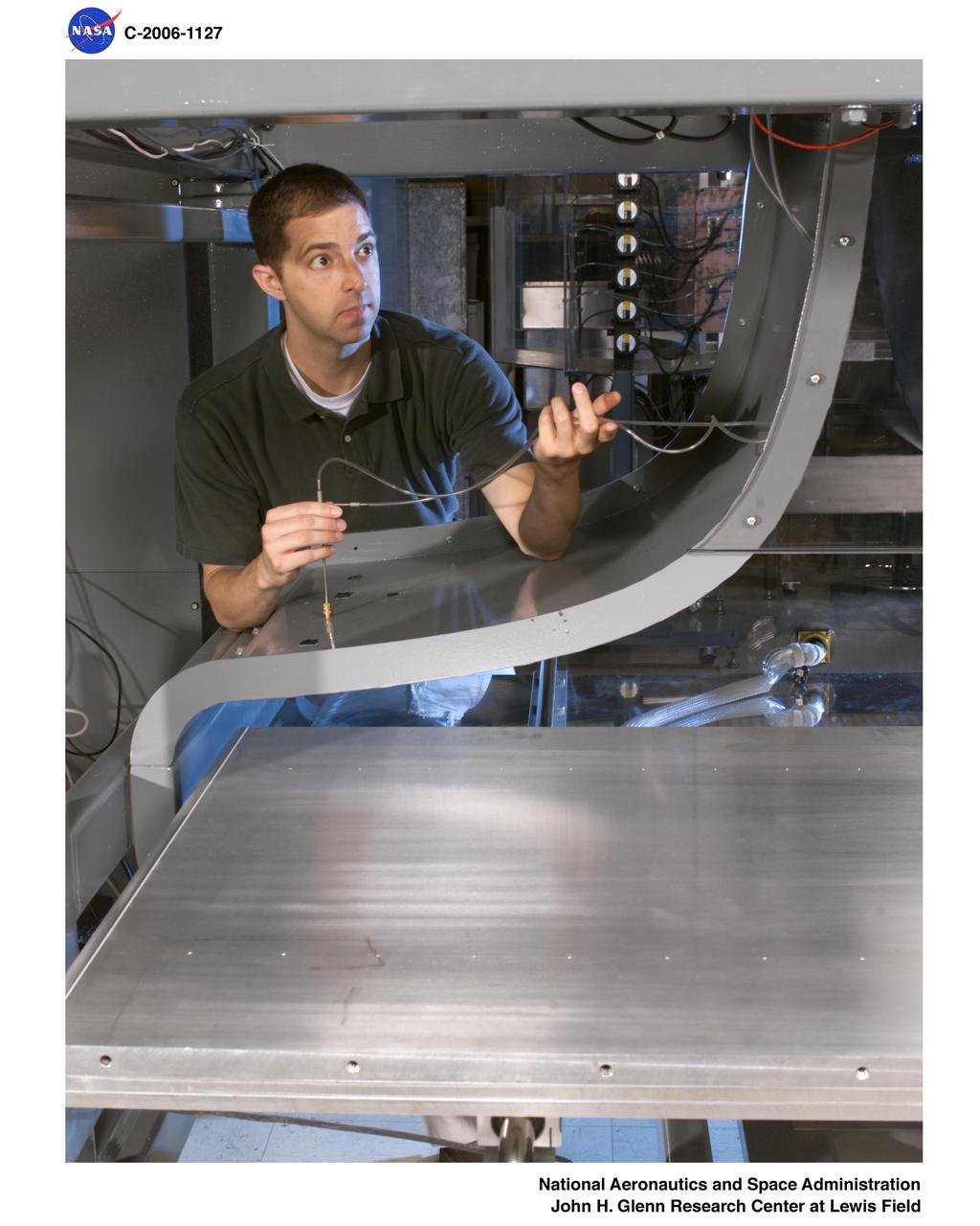
NASA Glenn’s Propulsion Systems Lab (PSL) is conducting research to characterize ice crystal clouds that can create a hazard to aircraft engines under certain conditions. The isokinetic probe (in gold) samples particles and another series of probes can measure everything from humidity to air pressure.
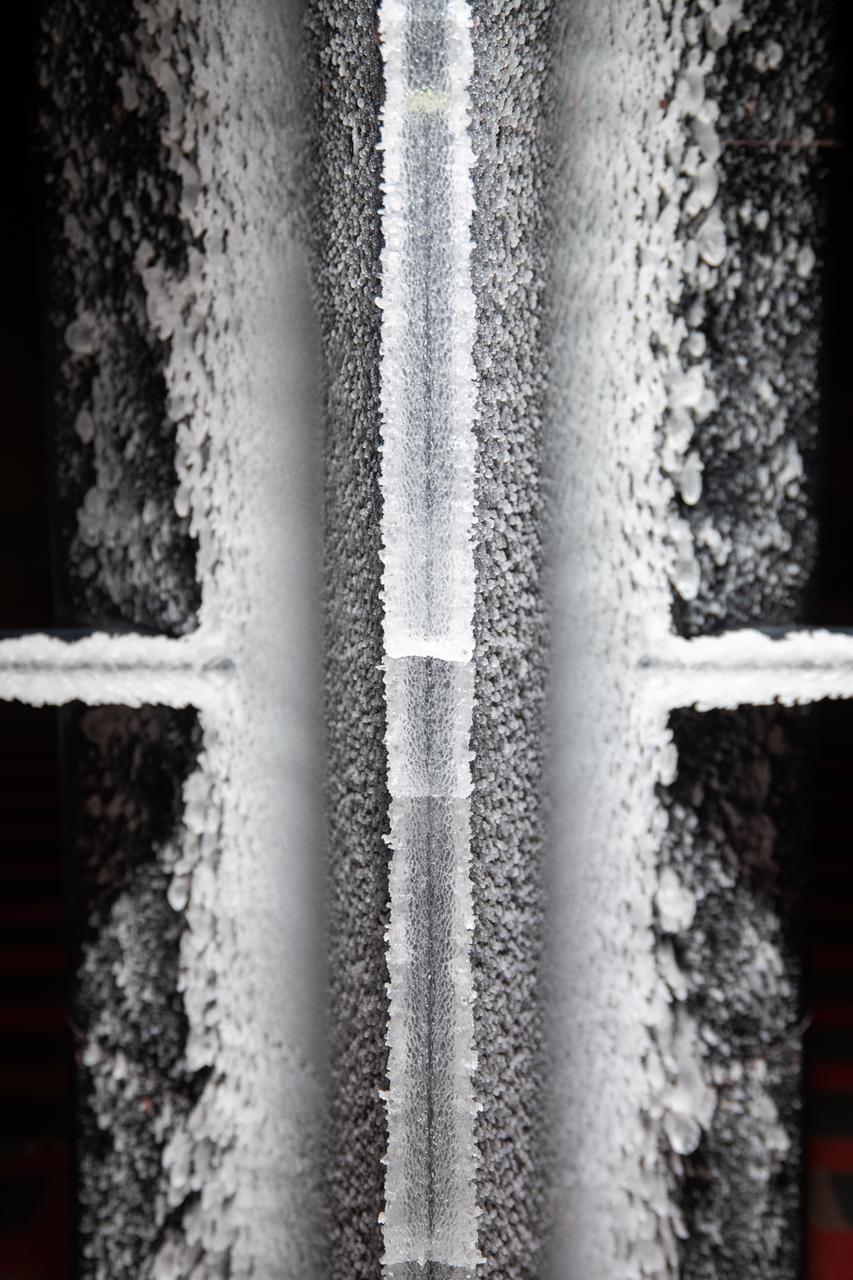
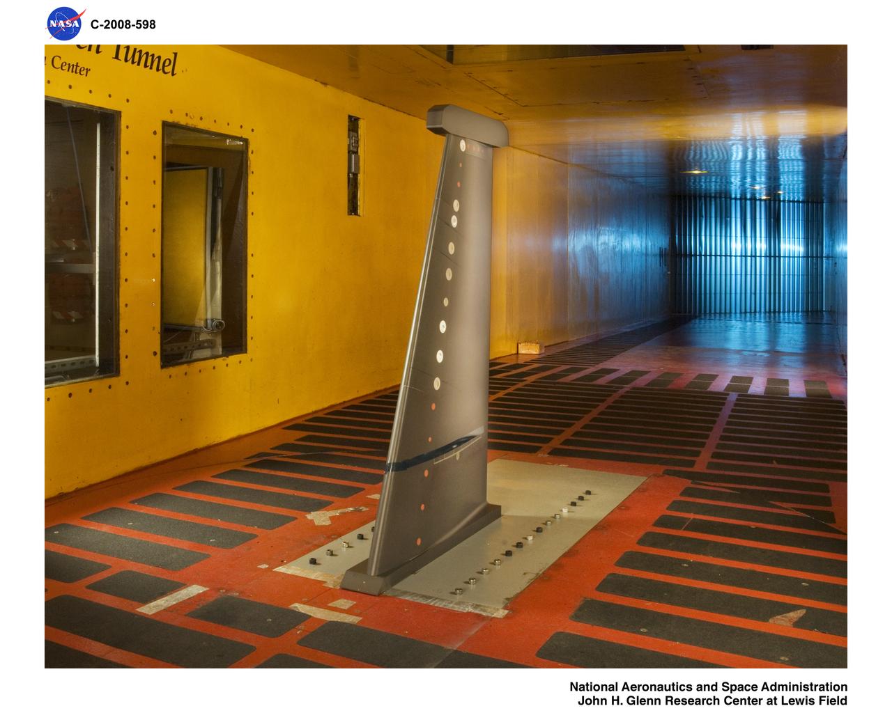
Ice built up on a test article at the at the Icing Research Tunnel as researchers study the icing physics that occur when aircraft fly through freezing weather conditions.
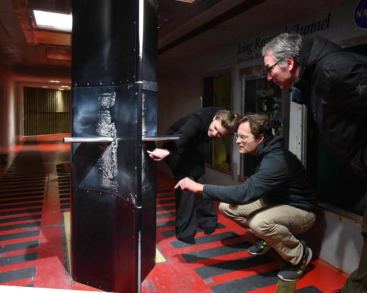
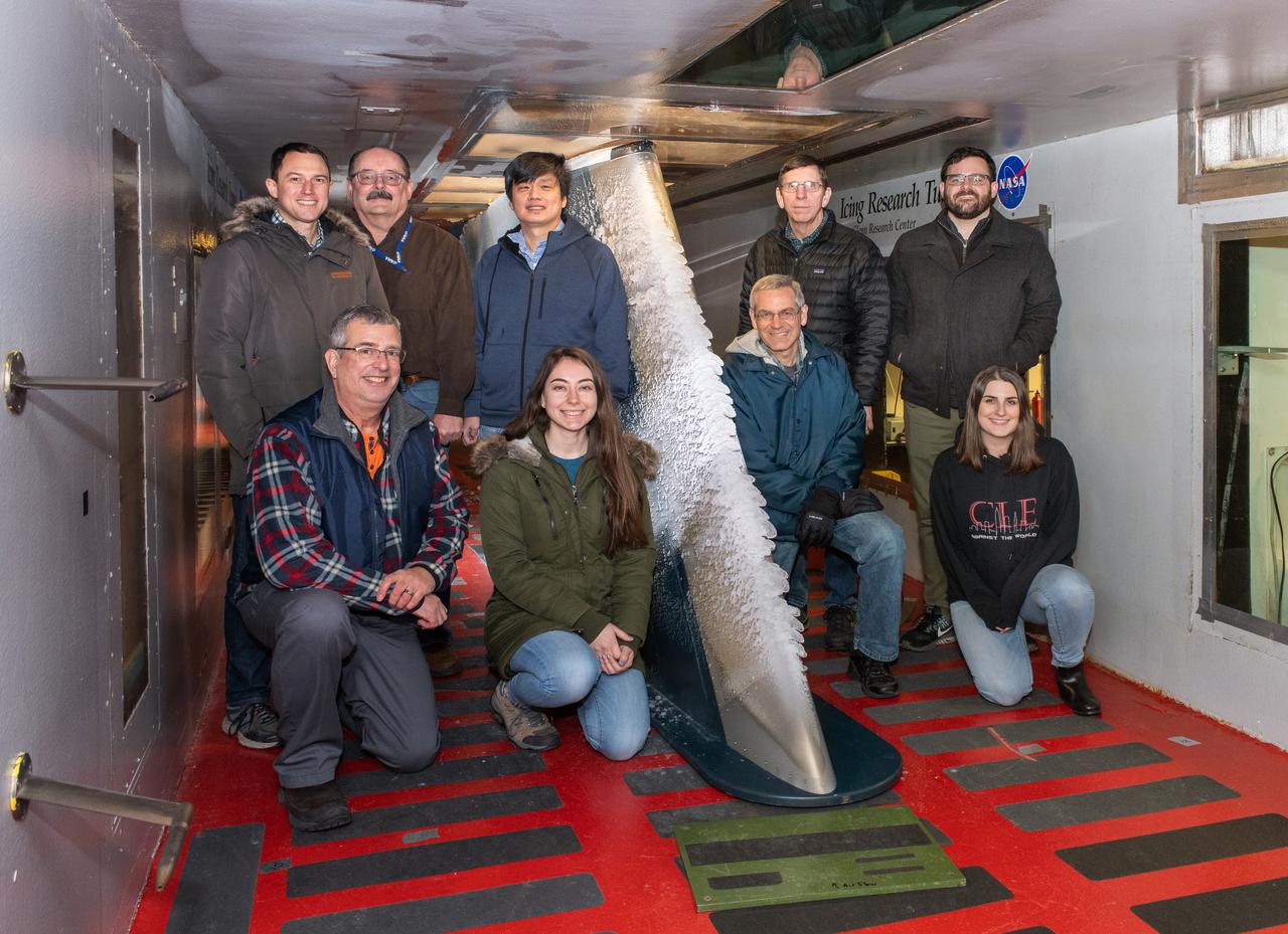
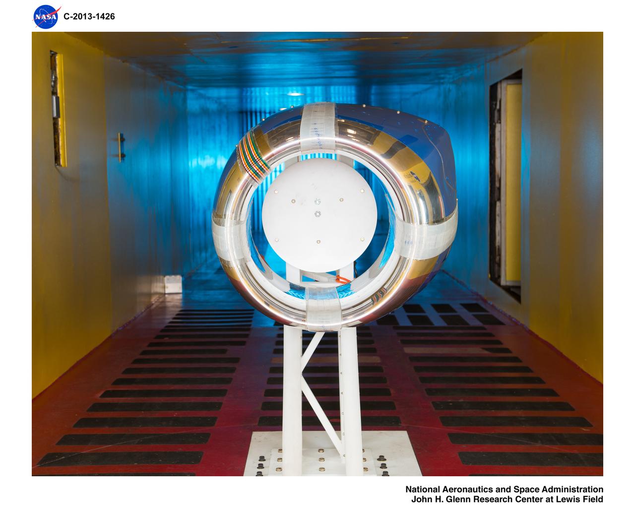
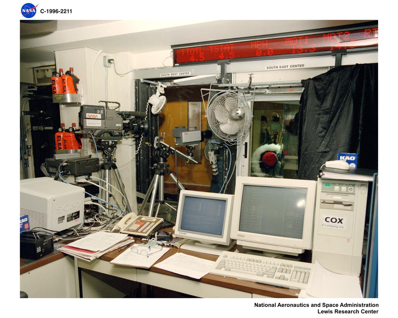
Pictured is a model to study the ice collection on struts in jet engines during flight. Researchers inspect the ice after the model encounters a simulated icing cloud during testing. Super cooled water created from the icing cloud that flows though the wind tunnel. The super cooled water forms ice on contact with the test model. Researchers then inspect the ice formation before laser scanning of the ice formation for further research and analysis.
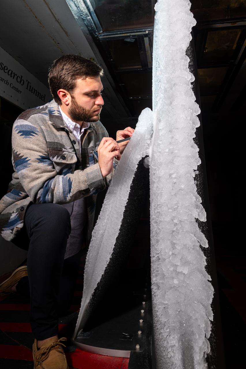
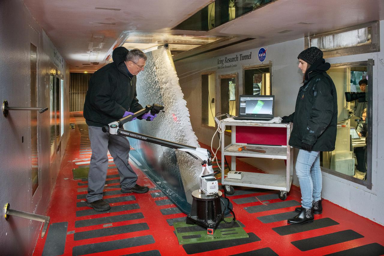
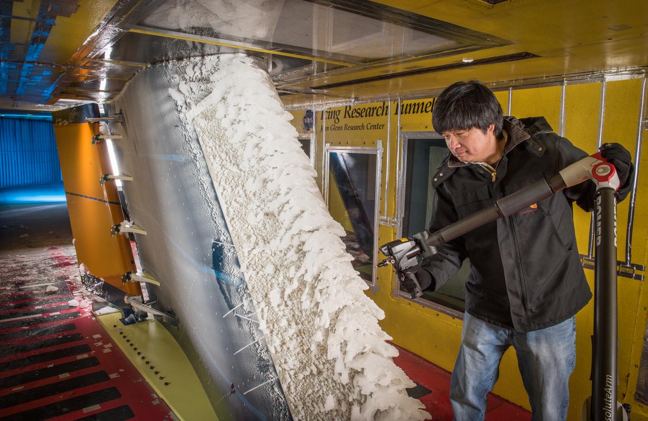
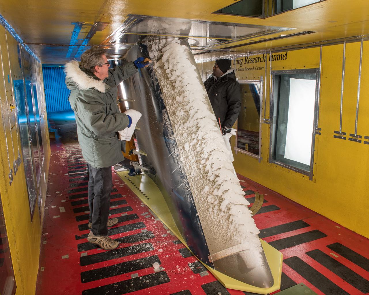
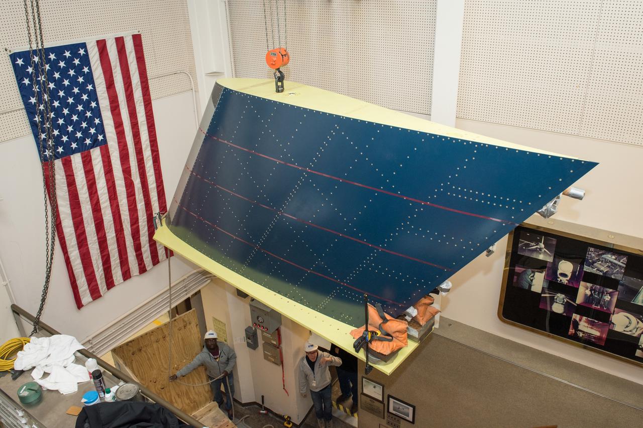
Thomas Ozoroski, an Icing Researcher, is shown documenting ice accretion on the leading edge of the next-generation Transonic Truss-Braced Wing design at NASA Glenn's Icing Research Center. This critical research will help understand icing effects for future, high-lift, ultra-efficient aircraft. Photo Credit: (NASA/Jordan Salkin)
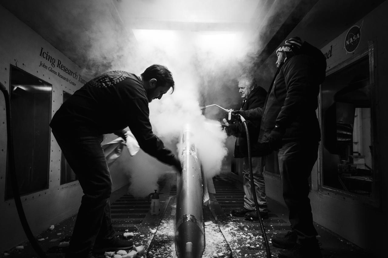
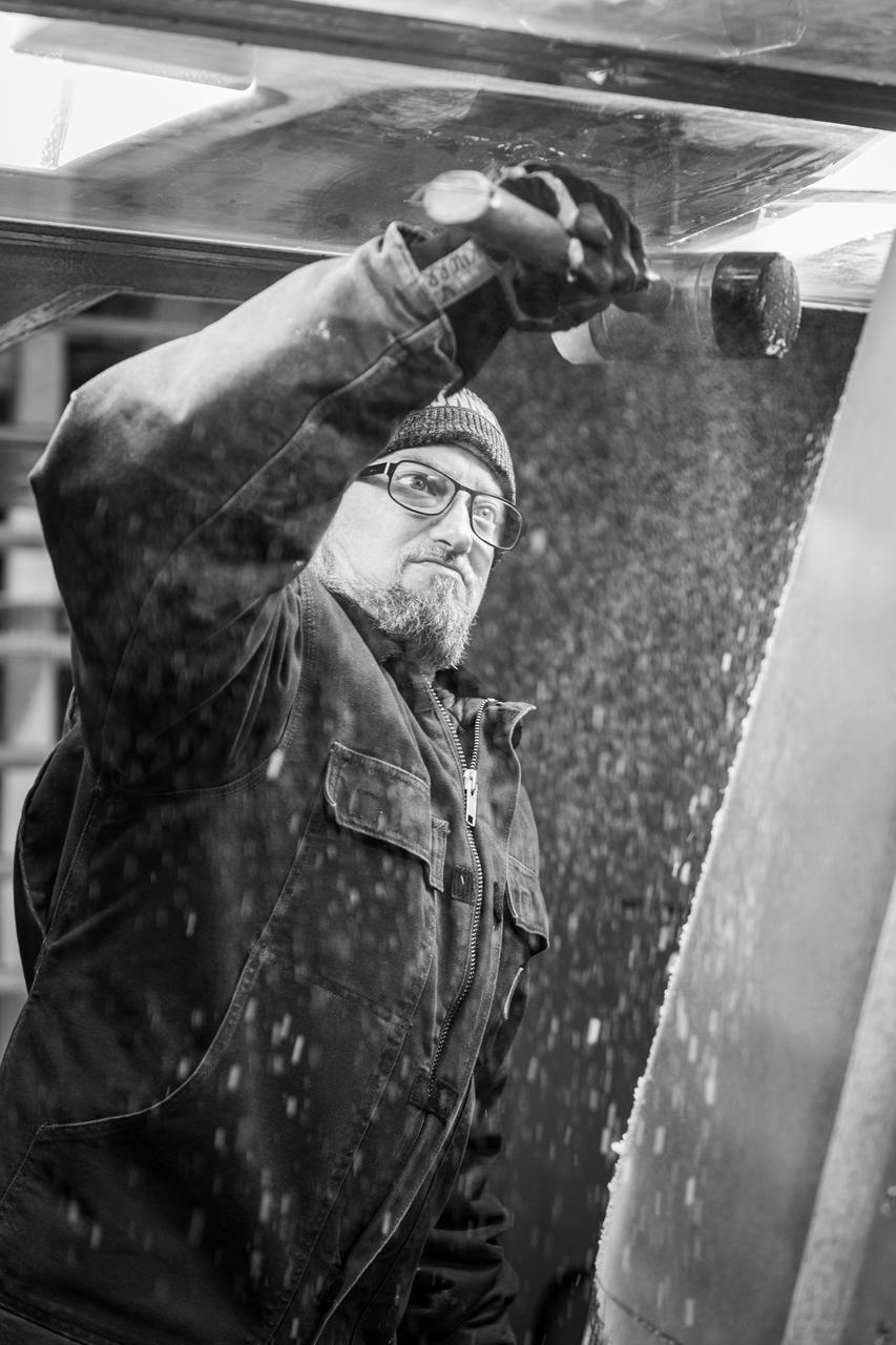
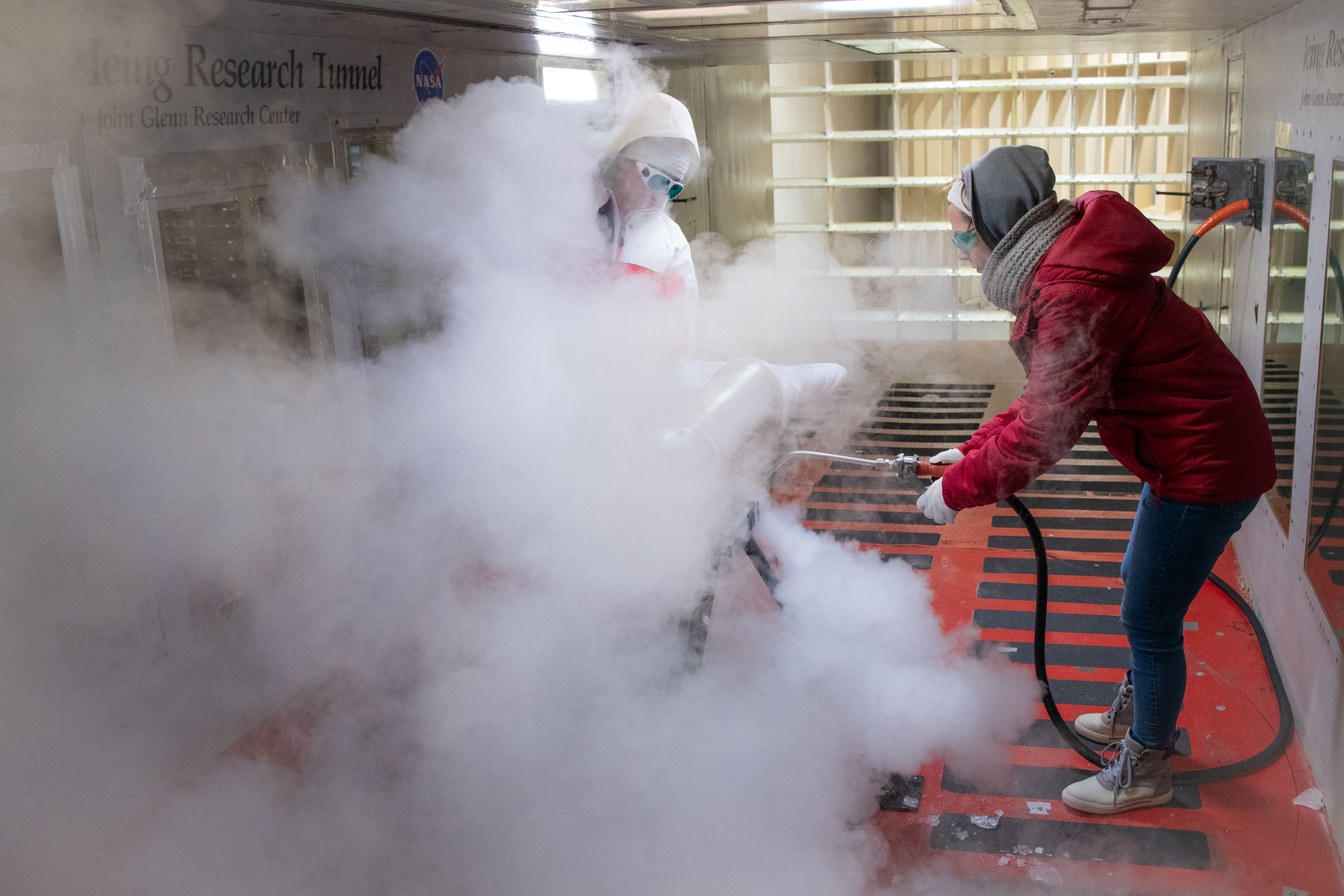
Technicians spray steam to help scrape off ice at the Icing Research Tunnel. The technicians need all the help they can get in sub-zero temperatures. Photo Credit: (NASA/Jordan Salkin)
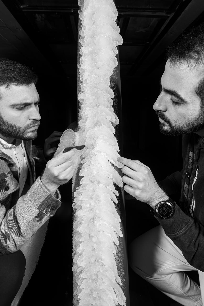
Zaid Sabri and Thomas Ozoroski, Icing Researchers, are shown documenting ice accretion on the leading edge of the next-generation Transonic Truss-Braced Wing design at NASA Glenn's Icing Research Center. This critical research will help understand icing effects for future, high-lift, ultra-efficient aircraft. Photo Credit: (NASA/Jordan Salkin)
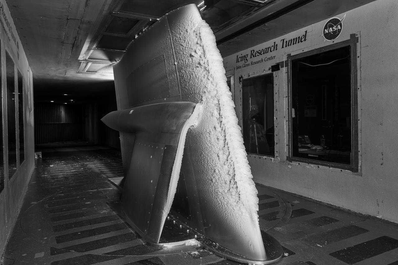
Ice accretion is shown on the leading edge of the next-generation Transonic Truss-Braced Wing design at NASA Glenn's Icing Research Center. This critical research will help understand icing effects for future, high-lift, ultra-efficient aircraft. Photo Credit: (NASA/Jordan Salkin)
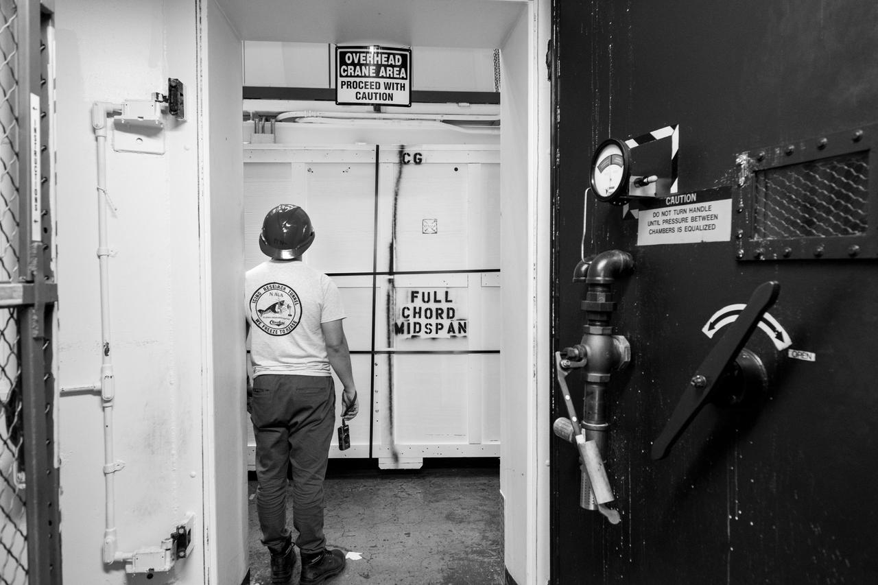
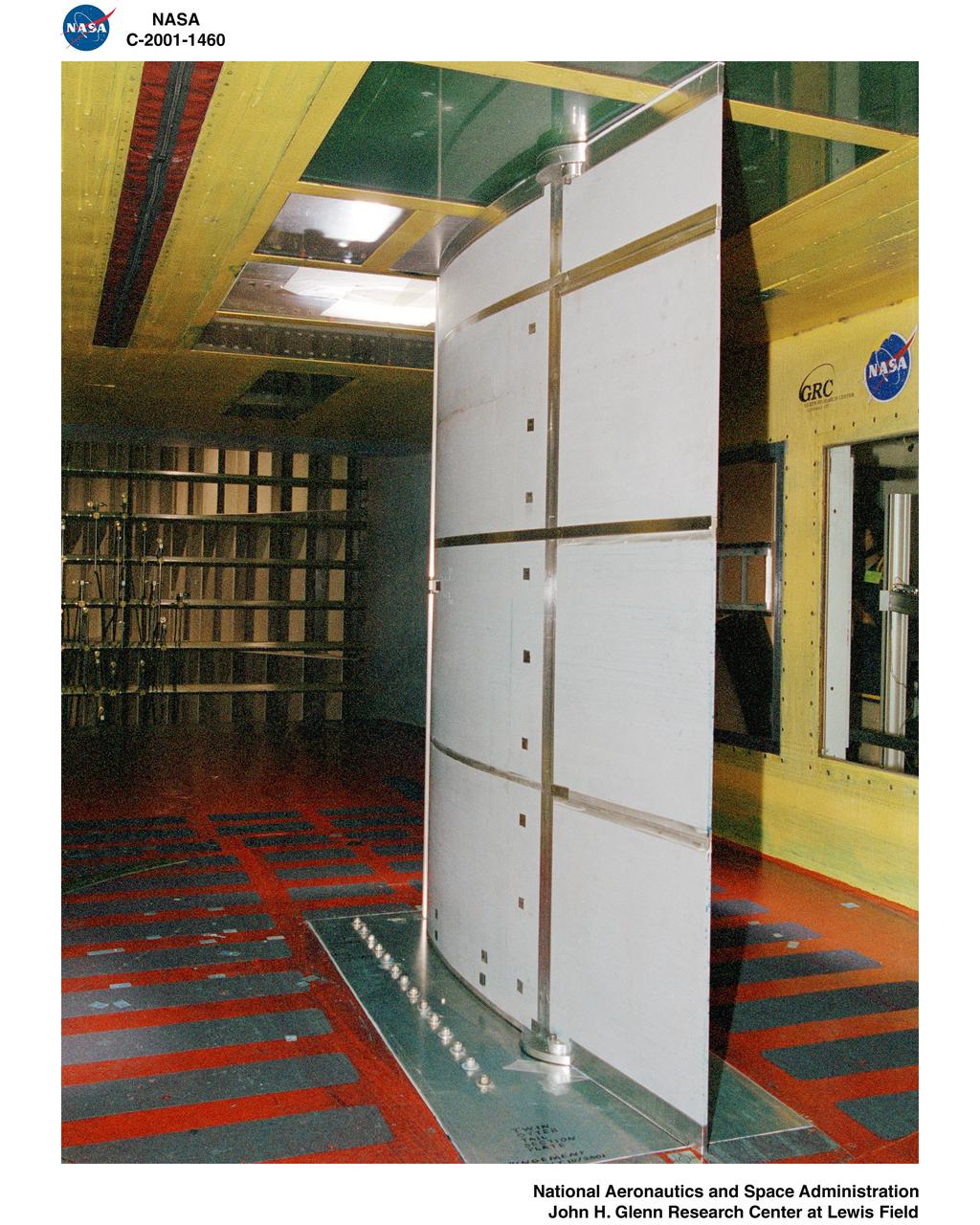
Common Research Model, CRM Full Chord and Midspan Test in the Icing Research Tunnel, IRT
CRM Full Chord Installation and Test Documentation Photos, Icing Research Tunnel
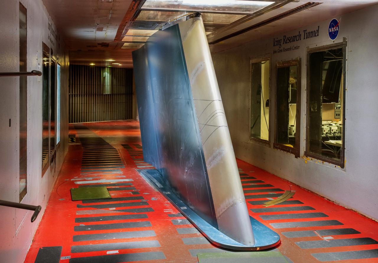
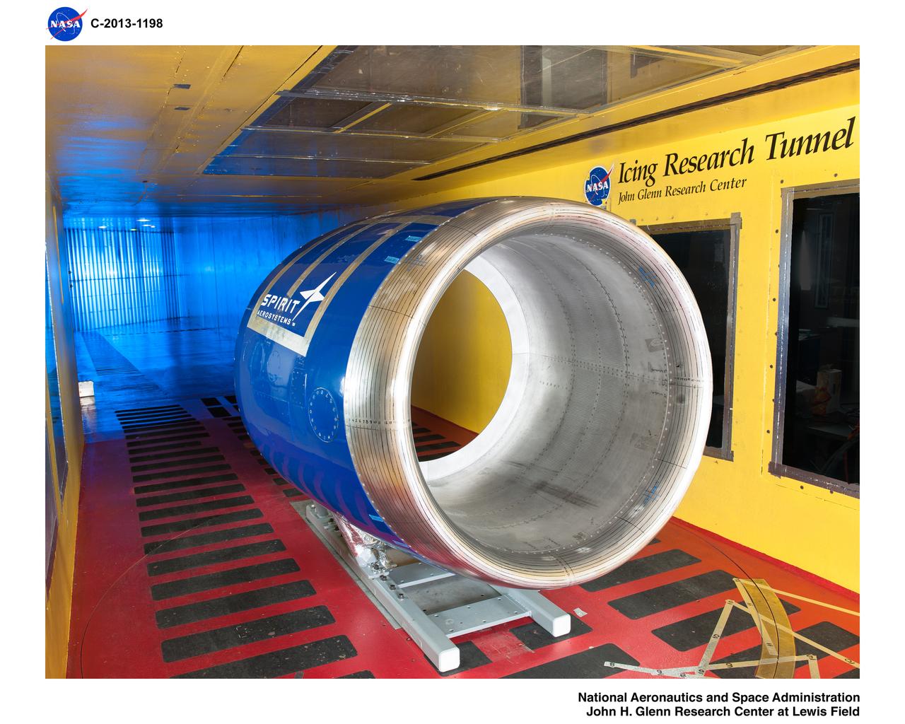
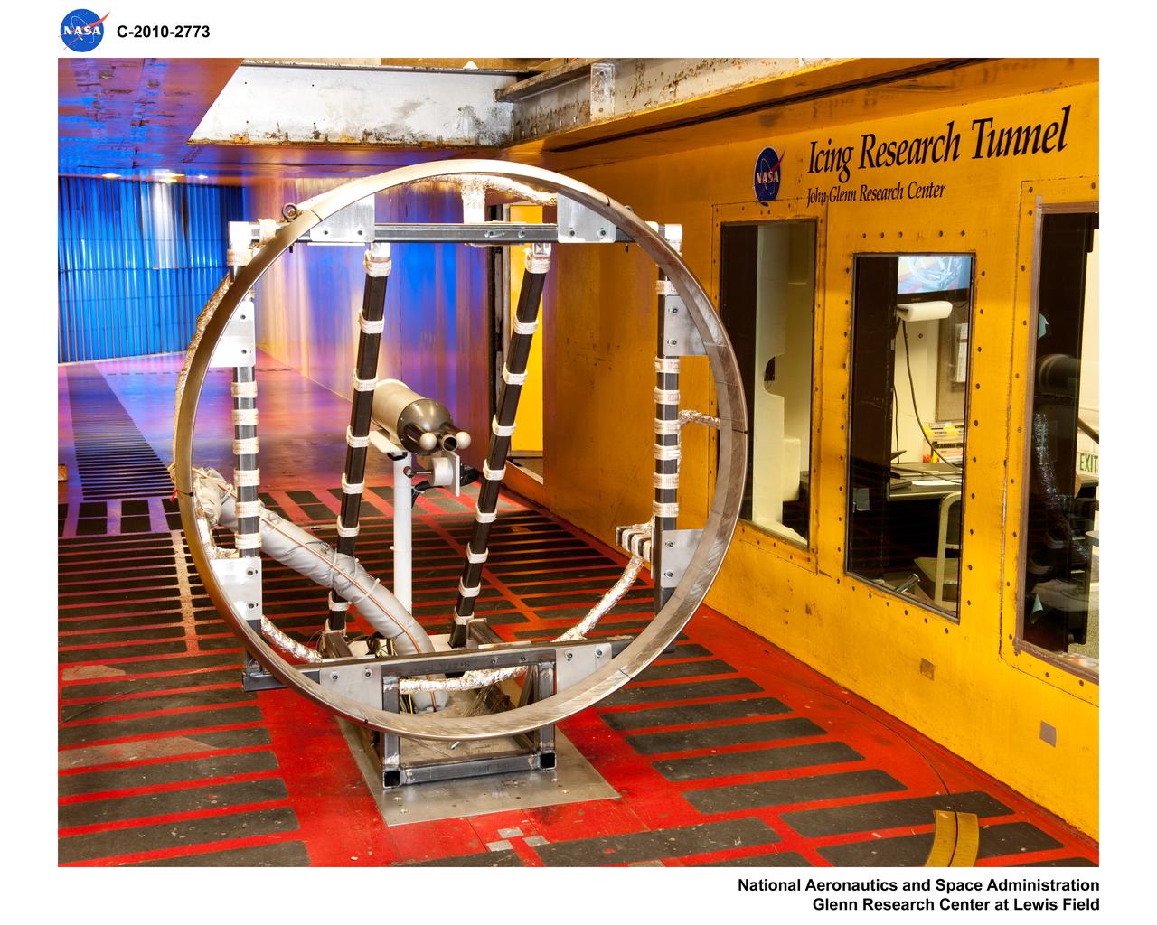
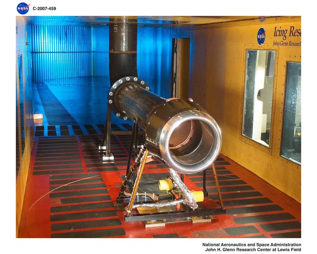
The Icing Research Tunnel (IRT) is the longest running, icing facility in the world and has been in operation since 1944. Most ice protection technologies in use today were largely developed at this facility. In this facility, natural icing conditions, such as the clouds being created here, are produced to test the effects of icing conditions on aircraft components such as wings tails and engine inlets.
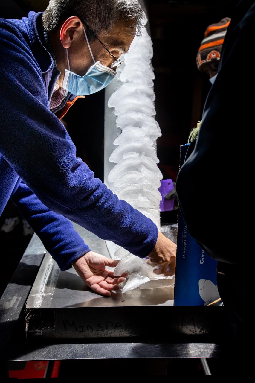
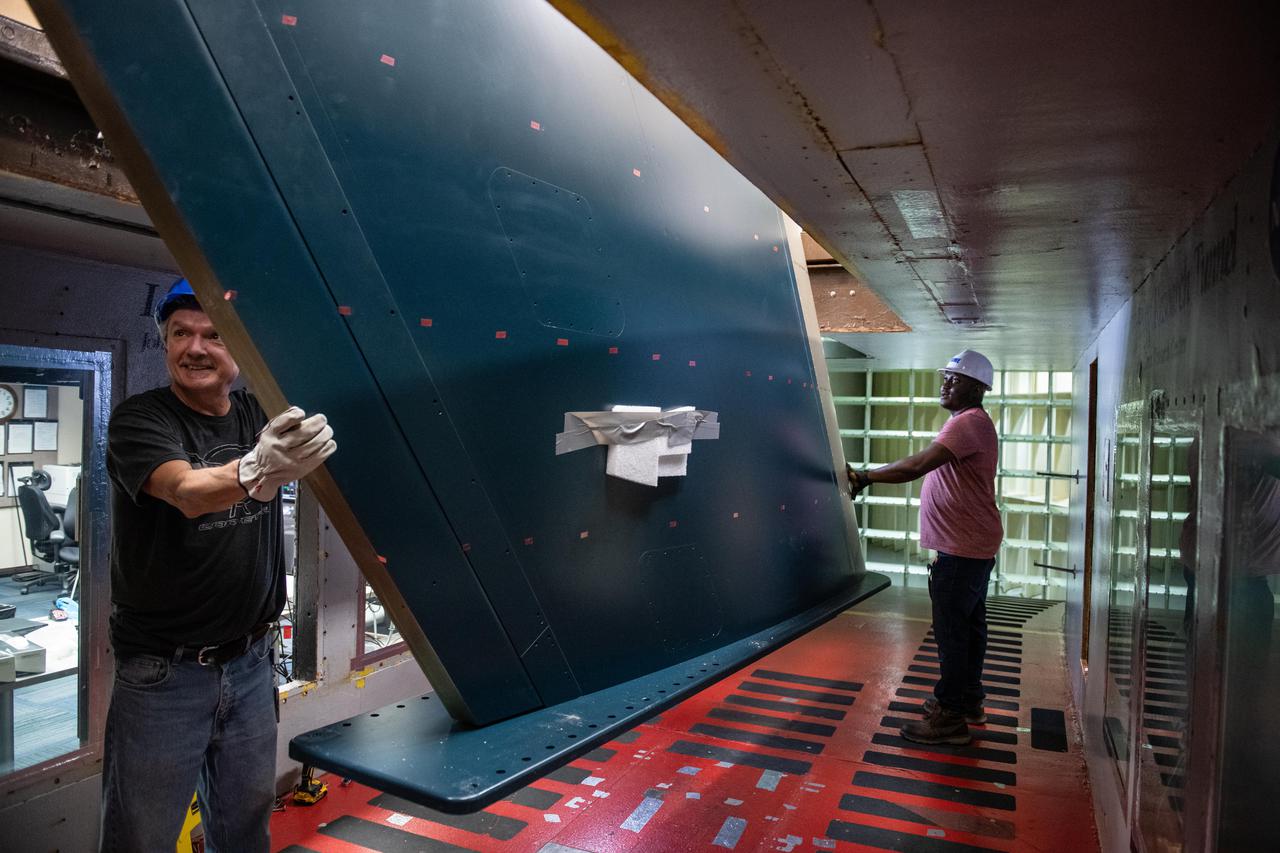
A technician is shown preparing the research model for its next test condition by removing ice accretion. Photo Credit: (NASA/Jordan Salkin)
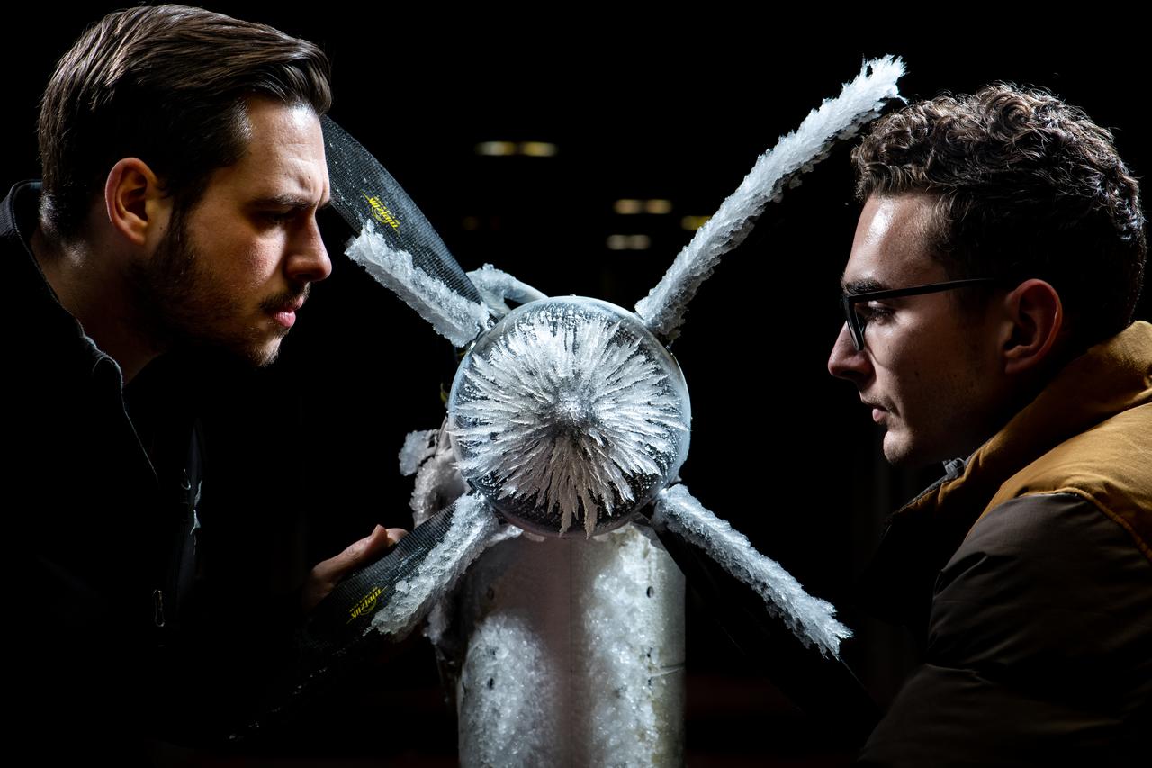
Curtis Flack (left) and Paul von Hardenberg (right) inspect the ice formation on the spinner of an Advanced Air Mobility proprotor model tested in the Icing Research Tunnel. The data from the test will be used by icing researchers to better understand the risks of icing on electric vertical takeoff and landing vehicles which will assist with the design and certification of new aircraft.
CRM Full Chord Installation and Test Documentation Photos, Icing Research Tunnel
CRM Full Chord Installation and Test Documentation Photos, Icing Research Tunnel
CRM Full Chord Installation and Test Documentation Photos, Icing Research Tunnel
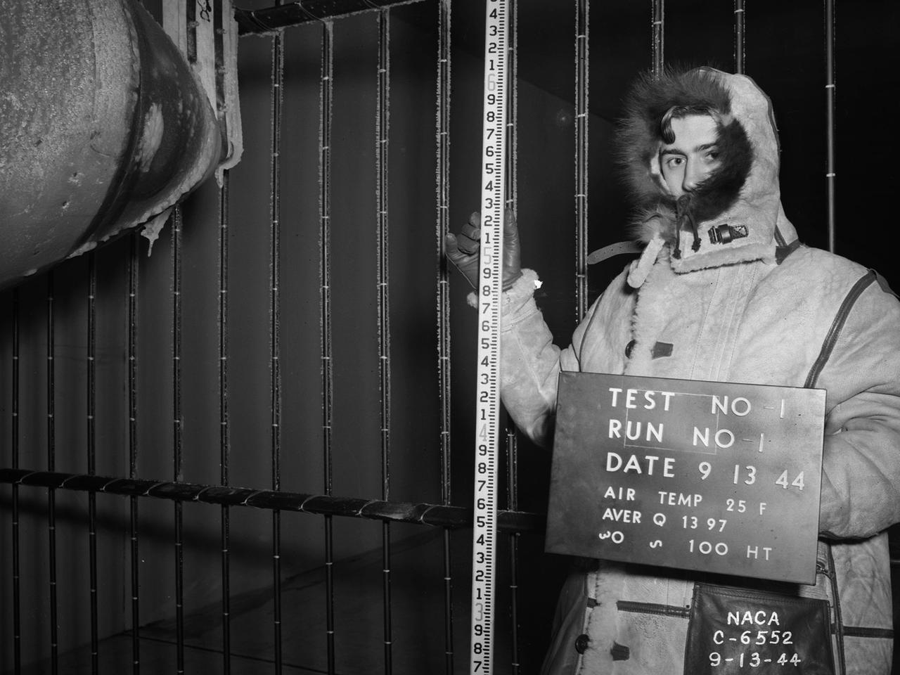
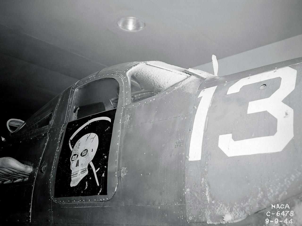
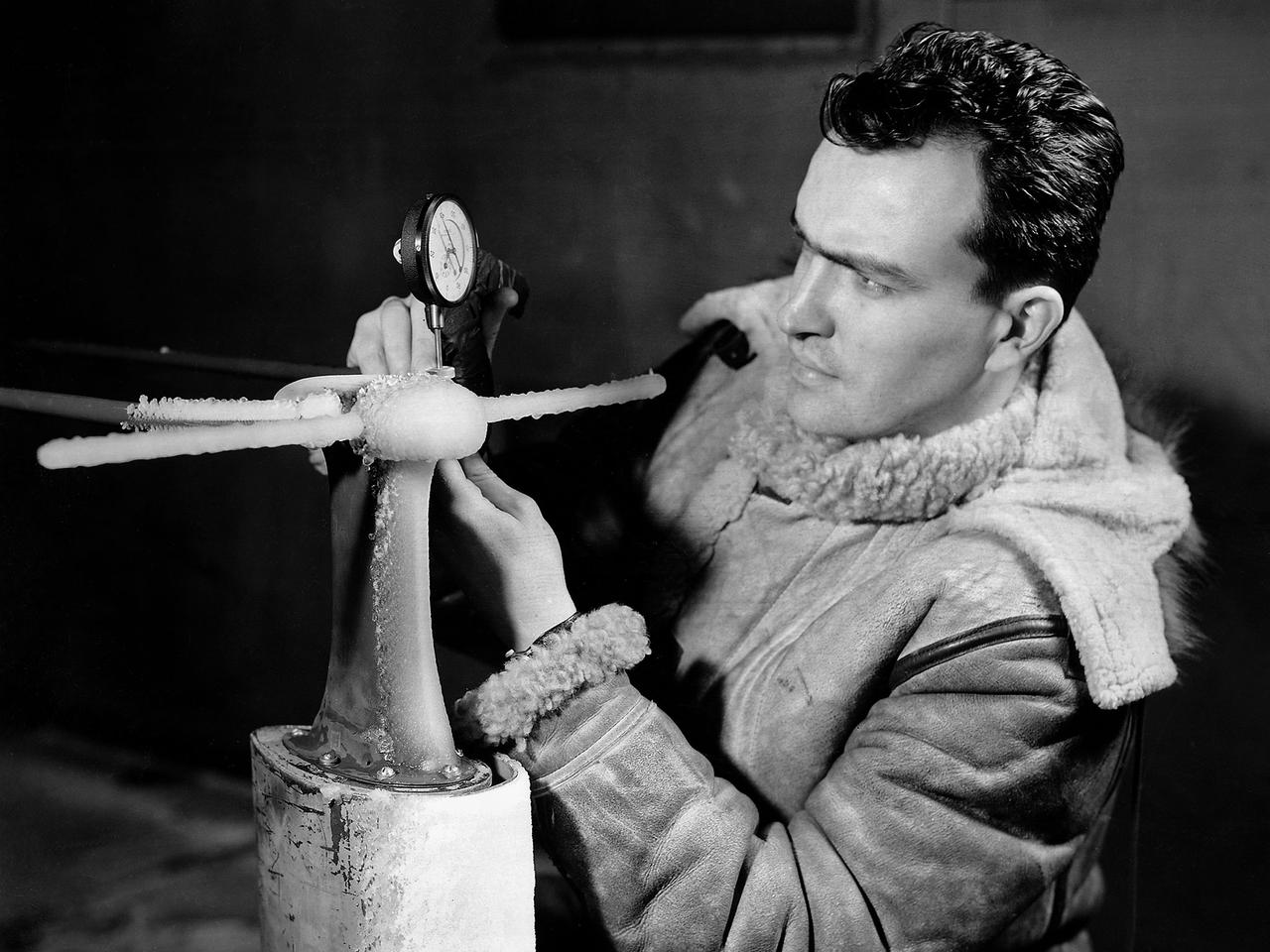
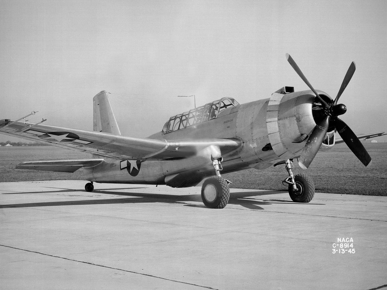
National Advisory Committee for Aeronautics (NACA) design engineers added the Icing Research Tunnel to the new Aircraft Engine Research Laboratory’s original layout to take advantage of the massive refrigeration system being constructed for the Altitude Wind Tunnel. The Icing Research Tunnel was built to study the formation of ice on aircraft surfaces and methods of preventing or eradicating that ice. Ice buildup adds extra weight, effects aerodynamics, and sometimes blocks airflow through engines. The Icing Research Tunnel is a closed-loop atmospheric wind tunnel with a 6- by 9-foot test section. The tunnel can produce speeds up to 300 miles per hour and temperatures from about 30 to –45⁰ F. Initially the tunnel used a spray bar system to introduce moisture into the airstream. NACA engineers struggled for nearly 10 years to perfect the spray system. The Icing Research Tunnel began testing in June of 1944. Initial testing, seen in this photograph, studied ice accumulation on propellers of a military aircraft. NACA reserach also produced a protected air scoop for the C–46 transport aircraft. A large number of C–46 aircraft were lost due to icing while flying supply runs over the Himalayas during World War II.
CRM Full Chord Installation and Test Documentation Photos, Icing Research Tunnel
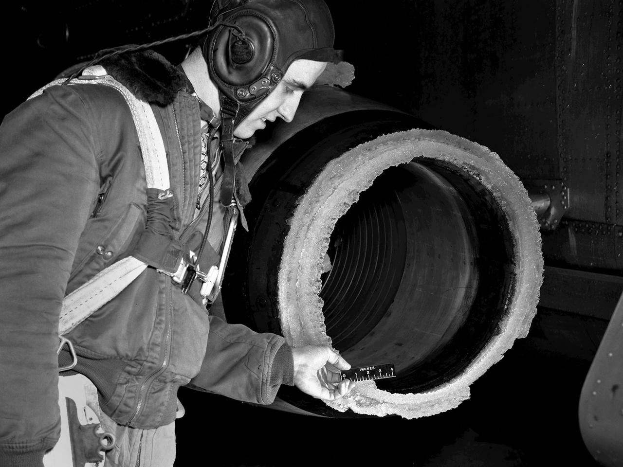
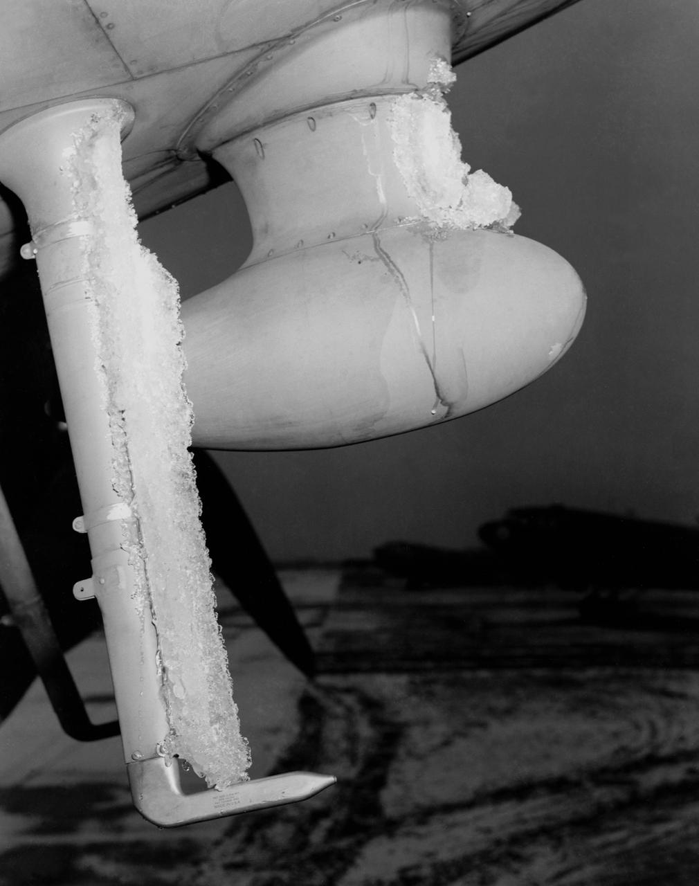
The National Advisory Committee for Aeronautics (NACA) Lewis Flight Propulsion Laboratory conducted an extensive icing research program in the late 1940s that included studies in the Icing Research Tunnel and using specially modified aircraft. One facet of this program was the investigation of the effects of icing on turbojets. Although jet engines allowed aircraft to pass through inclement weather at high rates of speed, ice accumulation was still a concern. The NACA’s B-24M Liberator was initially reconfigured with a General Electric I-16 engine installed in the aircraft’s waist compartment with an air scoop and spray nozzles to produce the artificial icing conditions. The centrifugal engine appeared nearly impervious to the effects of icing. Axial-flow jet engines, however, were much more susceptible to icing damage. The inlet guide vanes were particularly vulnerable, but the cowling’s leading edge, the main bearing supports, and accessory housing could also ice up. If pieces of ice reached the engine’s internal components, the compressor blades could be damaged. To study this phenomenon, a Westinghouse 24C turbojet, seen in this photograph, was installed under the B-24M’s right wing. In January 1948 flight tests of the 24C in icing conditions began. Despite ice buildup into the second stage of the compressor, the engine was able to operate at takeoff speeds. Researchers found the ice on the inlet vanes resulted in half of the engine’s decreased performance.
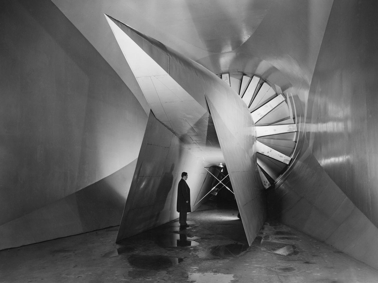
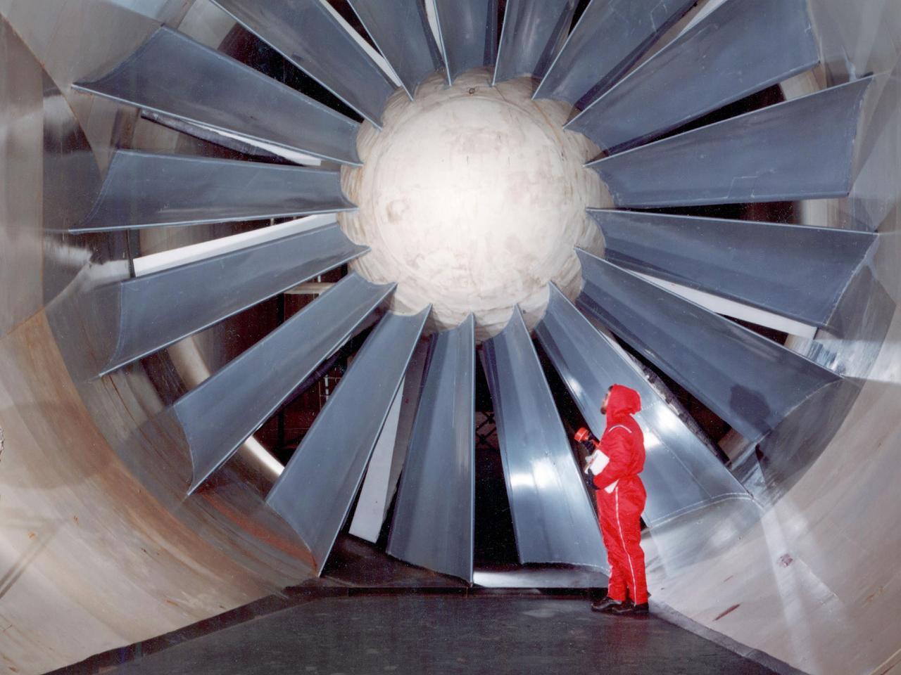
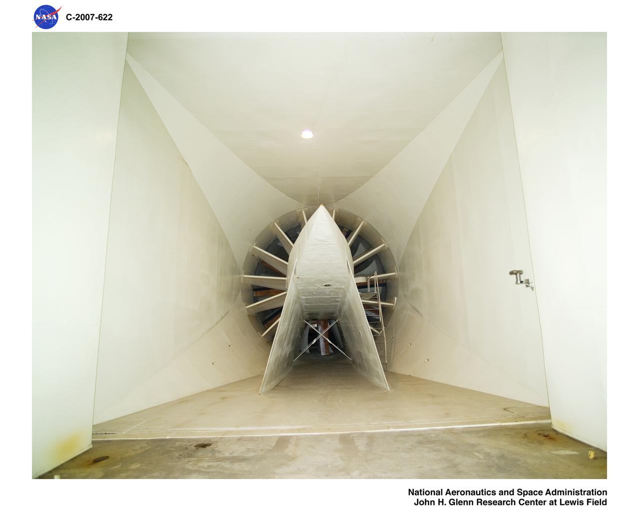
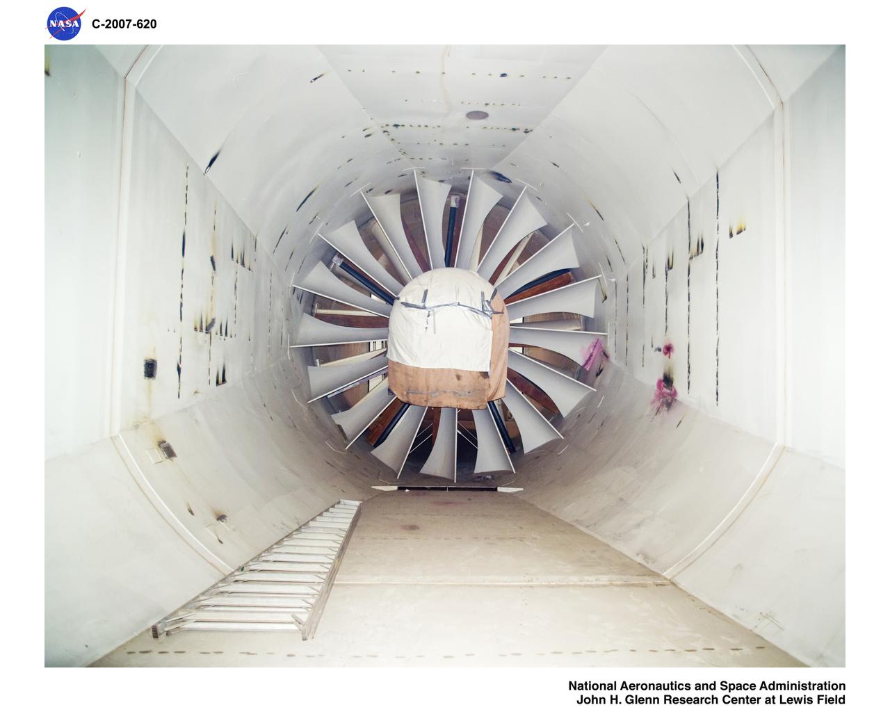
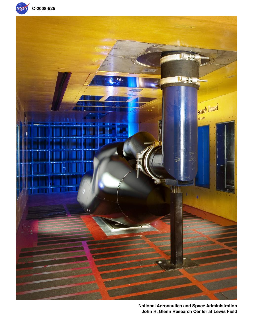
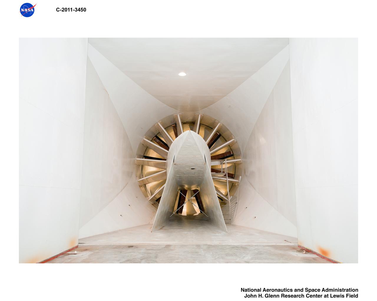
View of the drive fan for the Icing Research Tunnel at the National Advisory Committee for Aeronautics (NACA) Aircraft Engine Research Laboratory in Cleveland, Ohio. The tunnel was built in the early 1940s to study the formation of ice on aircraft surfaces and methods of preventing or eradicating that ice. Ice buildup adds extra weight, effects aerodynamics, and sometimes blocks airflow through engines. The original 4100-horsepower induction motor was coupled directly to the 24-foot-diameter fan. The 12 wooden fan blades were protected on their leading edge by a neoprene boot. The system could create air speeds up to 300 miles per hour through the tunnel’s 6- by 9-foot test section. The large tail faring extending from the center of the fan is used to guide the airflow down the tunnel in a uniform way. A new 5000-horsepower motor was installed in 1987, and the original fan blades were replaced in 1993.
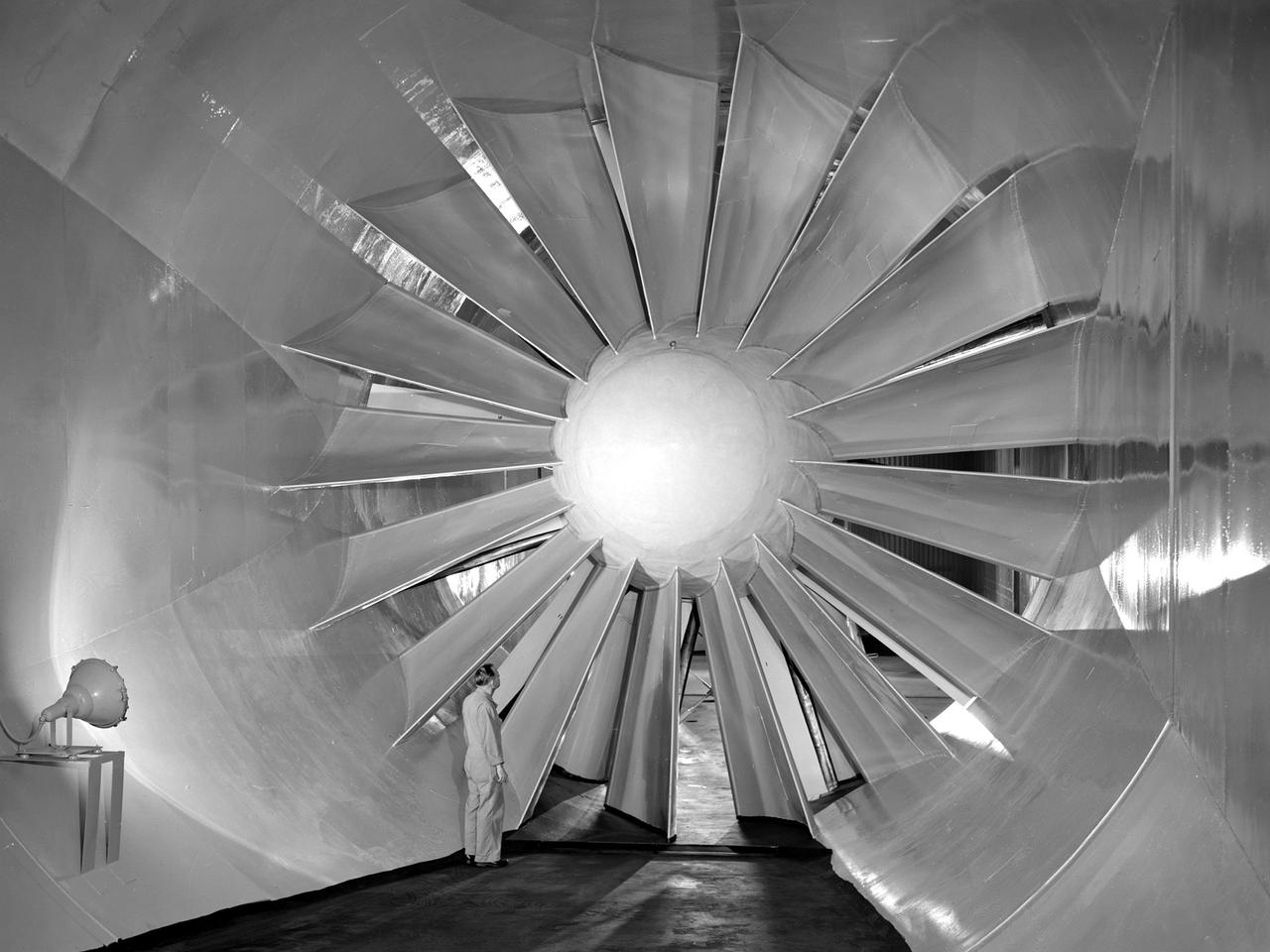
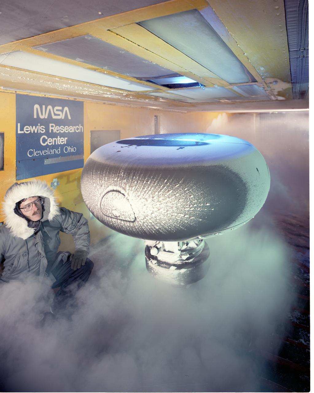
A researcher examines the drive fan inside the Icing Research Tunnel at the National Advisory Committee for Aeronautics (NACA) Flight Propulsion Research Laboratory in Cleveland, Ohio. The facility was built in the mid-1940s to simulate the atmospheric conditions that caused ice to build up on aircraft. Carrier Corporation refrigeration equipment reduced the internal air temperature to -45⁰ F, and a spray bar system injected water droplets into the air stream. The 24-foot diameter drive fan, seen in this photograph, created air flow velocities up to 400 miles per hour. The 1950s were prime years for the Icing Research Tunnel. NACA engineers had spent the 1940s trying to resolve the complexities of the spray bar system. The final system put into operation in 1950 included six horizontal spray bars with 80 nozzles that produced a 4- by 4-foot cloud in the test section. The icing tunnel was used for extensive testing of civilian and military aircraft components in the 1950s. The NACA also launched a major investigation of the various methods of heating leading edge surfaces. The hot-air anti-icing technology used on today’s commercial transports was largely developed in the facility during this period. Lewis researchers also made significant breakthroughs with icing on radomes and jet engines. Although the Icing Research Tunnel yielded major breakthroughs in the 1950s, the Lewis icing research program began tapering off as interest in the space program grew. The icing tunnel’s use declined in 1956 and 1957. The launch of Sputnik in October 1957 signaled the end of the facility’s operation. The icing staff was transferred to other research projects and the icing tunnel was temporarily mothballed.

Technicians set up test hardware inside the test section of the Icing Research Tunnel at the National Aeronautics and Space Administration (NASA) Lewis Research Center. The Icing Research Tunnel was built in the early 1940s to study the formation of ice on aircraft surfaces and develop methods of preventing or eradicating that ice. Ice buildup is dangerous because it adds extra weight, effects aerodynamics, and sometimes blocks air flow through engines. The Icing Research Tunnel is a closed-loop atmospheric wind tunnel with a 6- by 9-foot test section. The tunnel can produce speeds up to 300 miles per hour and temperatures from 30 to -45 °F. NACA engineers struggled initially to perfect a spray bar system to introduce moisture into the airstream. The tunnel was shut down in the late 1950s as the center focused its energy exclusively on space. Industrial customers began using the tunnel sporadically, then steadily, in the 1960s. Boeing, Aerojet, Lockheed, Sikorsky, Beech and others ran tests during the 1960s. Boeing analyzed engine inlets for the CH-47 Chinook, CH-46 (Sea Knight) and CH-113. This photograph was taken during a series of 100 ice-phobic coatings for the Federal Aviation Administration. They found that many of the coatings reduced ice adhesion to the test sample, but they could not be used for aircraft applications.
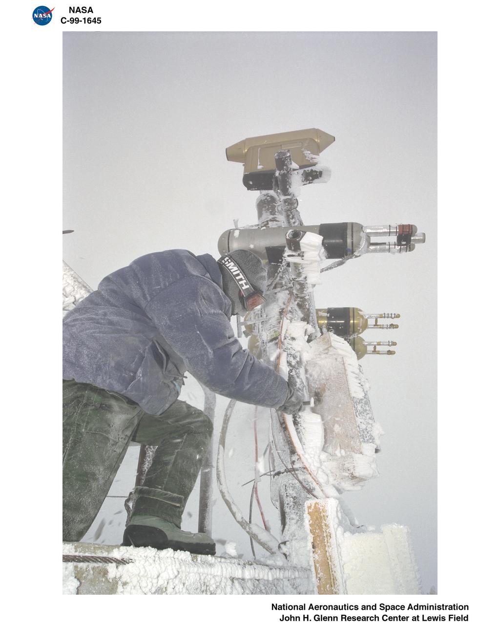
Test engineers clean the ice cloud detection probe in the Icing Research Tunnel in between test runs. Steam is used to melt the accumulated ice on the detection probe. The test engineers need to wear goggles to protect them from the laser light that the probe emits. The laser detects water content and ice particles in the cloud that the wind tunnel produces. This process is done to calibrate the tunnel for research by characterizing the cloud flow.

Significant ice build-up on the Simulated Inter-compressor Duct Research Model (SIDRM) at the Icing Research Tunnel. Photo Credit: (NASA/Jordan Salkin)
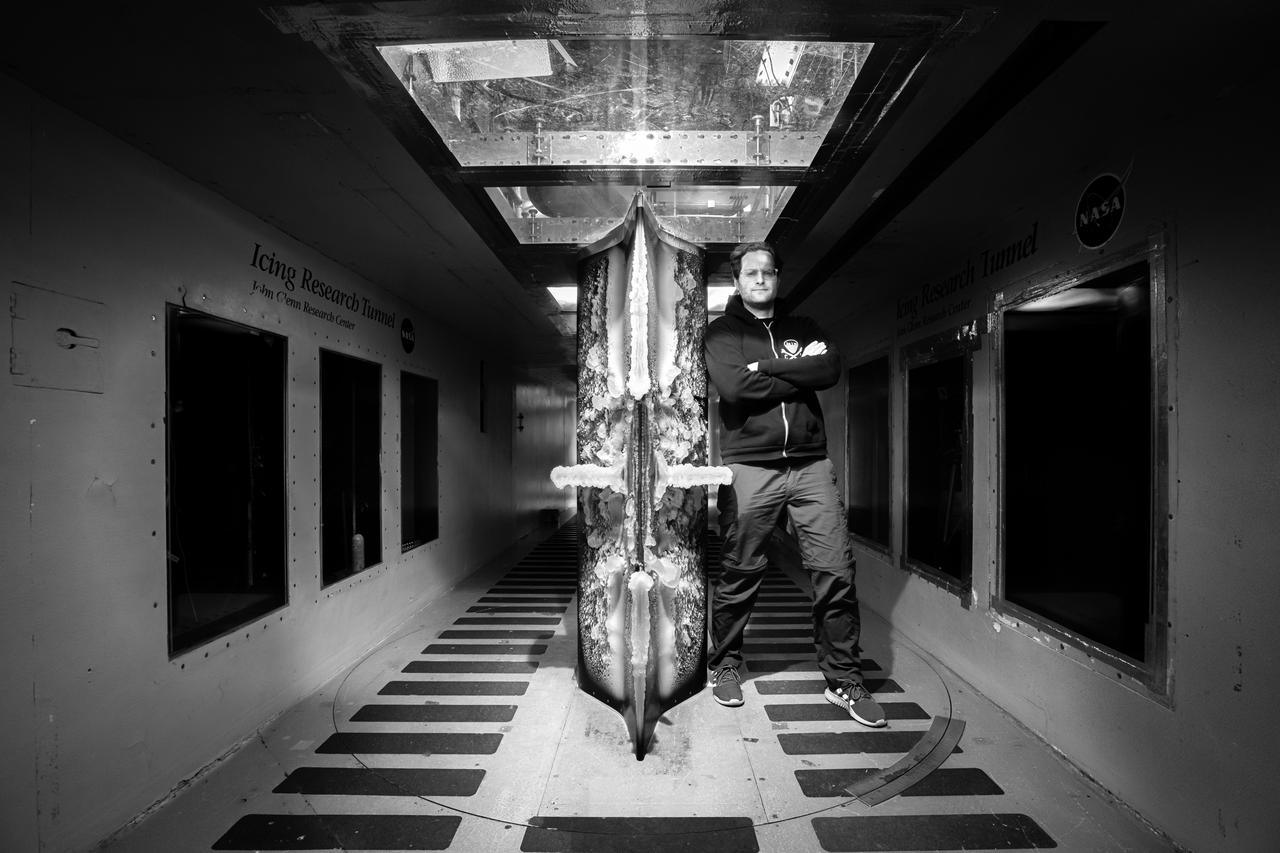
Lead researcher Tadas Bartkus poses after a run of his test with significant ice build-up on the Simulated Inter-compressor Duct Research Model (SIDRM) at the Icing Research Tunnel. Photo Credit: (NASA/Jordan Salkin)
An AH-64 (Apache) Longbow fire control full size radar photographed during icing tests in the Icing Research wind tunnel. Built at the end of World War II, the Icing Research Tunnel is the oldest and largest refrigerated icing wind tunnel in the world. It can produce winds that travel up to 395 miles per hour and reach temperatures as low as -30 degrees Fahrenheit. The facility simulates ice formation during flight by spraying a cloud of super-cooled water droplets onto an aircraft component or model.
A Bell P-39 Airacobra in the NACA Aircraft Engine Research Laboratory’s Icing Research Tunnel for a propeller deicing study. The tunnel, which began operation in June 1944, was built to study the formation of ice on aircraft surfaces and methods of preventing or eradicating that ice. Ice buildup adds extra weight to aircraft, effects aerodynamics, and sometimes blocks airflow through engines. NACA design engineers added the Icing Research Tunnel to the new AERL’s original layout to take advantage of the massive refrigeration system being constructed for the Altitude Wind Tunnel. The Icing Research Tunnel is a closed-loop atmospheric wind tunnel with a 6- by 9-foot test section. The tunnel can produce speeds up to 300 miles per hour and temperatures from about 30 to –45⁰ F. During World War II AERL researchers analyzed different ice protection systems for propeller, engine inlets, antennae, and wings in the icing tunnel. The P-39 was a vital low-altitude pursuit aircraft of the US during the war. NACA investigators investigated several methods of preventing ice buildup on the P-39’s propeller, including the use of internal and external electrical heaters, alcohol, and hot gases. They found that continual heating of the blades expended more energy than the aircraft could supply, so studies focused on intermittent heating. The results of the wind tunnel investigations were then compared to actual flight tests on aircraft.
The drive fan for the Icing Research Tunnel at the National Aeronautics and Space Administration (NASA) Lewis Research Center in Cleveland, Ohio. The Lewis Icing Research Program, which began during World War II, utilized both research aircraft and the icing tunnel throughout the 1940s and 1950s. The research program was cancelled in 1958 as Lewis focused on space. The tunnel continued to be used occasionally for industrial customers in the 1960s and early 1970s. Lewis’ icing research was formally reinstituted just months before this photograph in 1978. The Icing Research Tunnel’s original 4100-horsepower induction motor was coupled directly to the 24-foot-diameter fan. Neoprene boots protected the leading edges of the 12 spruce fan blades. The system generated air speeds up to 300 miles per hour through the tunnel’s 6- by 9-foot test section. A large tail faring extended from the center of the fan to uniformly guide the airflow down the tunnel. NASA Headquarters ordered modifications to the Icing Research Tunnel in 1985 after wooden fan blades in a wind tunnel at Langley Research Center failed. Despite the fact that the large hub, seen in the center of the fan, provided an extra layer of protection against blade failure, Headquarters ordered the installation of a new set of wooden blades. The blades were ordered but not installed. The tunnel technicians instead agreed to inspect the fan after each run. A new 5000-horsepower motor was installed in 1987, and the original fan blades were finally replaced in 1993.
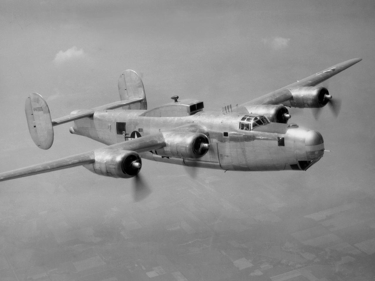
A Consolidated B-25M Liberator modified for icing research by the National Advisory Committee for Aeronautics (NACA) Lewis Flight Propulsion Laboratory. NACA Lewis performed a limited amount of icing research during World War II, but the program expanded significantly in 1946. The accumulation of ice on aircraft was a continual problem. The ice formations could result in extra weight, aerodynamic penalties, and blockage engine inlets. Although the Lewis icing researchers utilized numerous aircraft, the program’s two workhorses were the B-24M Liberator, seen here, and a North American XB-25E Mitchell. The Consolidated Aircraft Company created the four-engine bomber in the early 1940s. During World War II the bomber was employed on long-duration bombing missions in both Europe and the Pacific. Production of the B-24M version did not begin until October 1944 with the end of the war in Europe approaching. This resulted in scores of unneeded bombers when hostilities ended. This B-24M arrived at the NACA Lewis laboratory in November 1945. At Lewis the B-24M was repeatedly modified to study ice accretion on aircraft components. Researchers analyzed different anti-icing and deicing strategies and gathered statistical ice measurement data. The B-24M was also used to study ice buildup on jet engines. A General Electric I-16 engine was installed in the aircraft’s waist compartment with an air scoop on the top of the aircraft to duct air to the engine. Water spray nozzles inside the aircraft were employed to simulate icing conditions at the turbojet’s inlet.
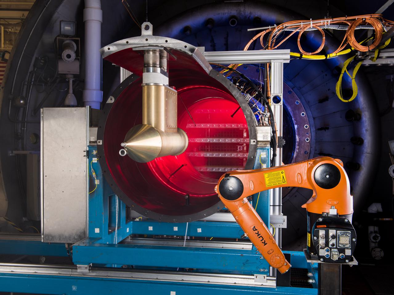
NASA Glenn’s Propulsion Systems Lab (PSL) is conducting research to characterize ice crystal clouds that can create a hazard to aircraft engines in certain conditions. With specialized equipment, scientists can create a simulated ice crystal cloud with the set of bars in the back spraying out a mist. The red area includes lasers, which measure the intensity of the cloud and a series of probes to measure everything from humidity to air pressure. The isokinetic probe (in gold) samples particles and the robotic arm (in orange) has a test tube on the end that catches ice particles for further measuring. NASA Glenn’s PSL is the only place in the world which can create these kind of ice crystal cloud conditions.
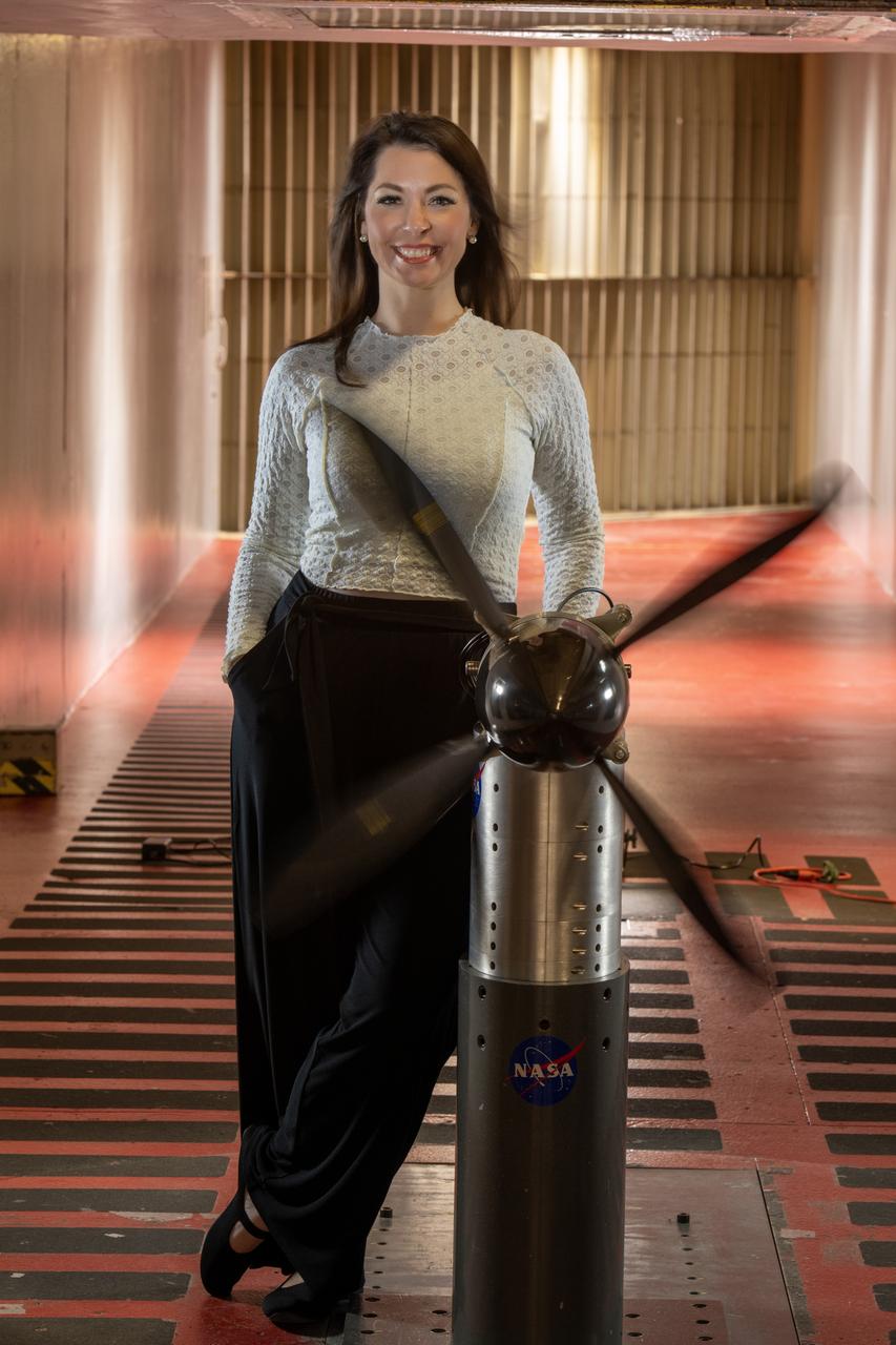
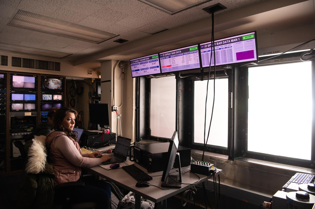
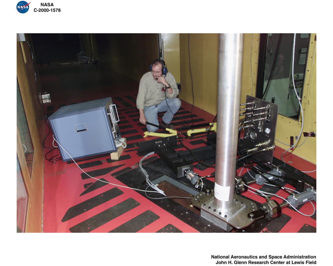
Emily Timko, featured in a Faces of NASA article, poses in the IRT (Icing Research Tunnel) where she works as a “cloud engineer”. She is a Mechanical Test Engineer and works to create unique water spray conditions that simulate icing clouds in the natural aircraft flight environment. Shown in the photo is a test article of a rotating propeller configuration that the IRT researchers are investigating ice accretion with.
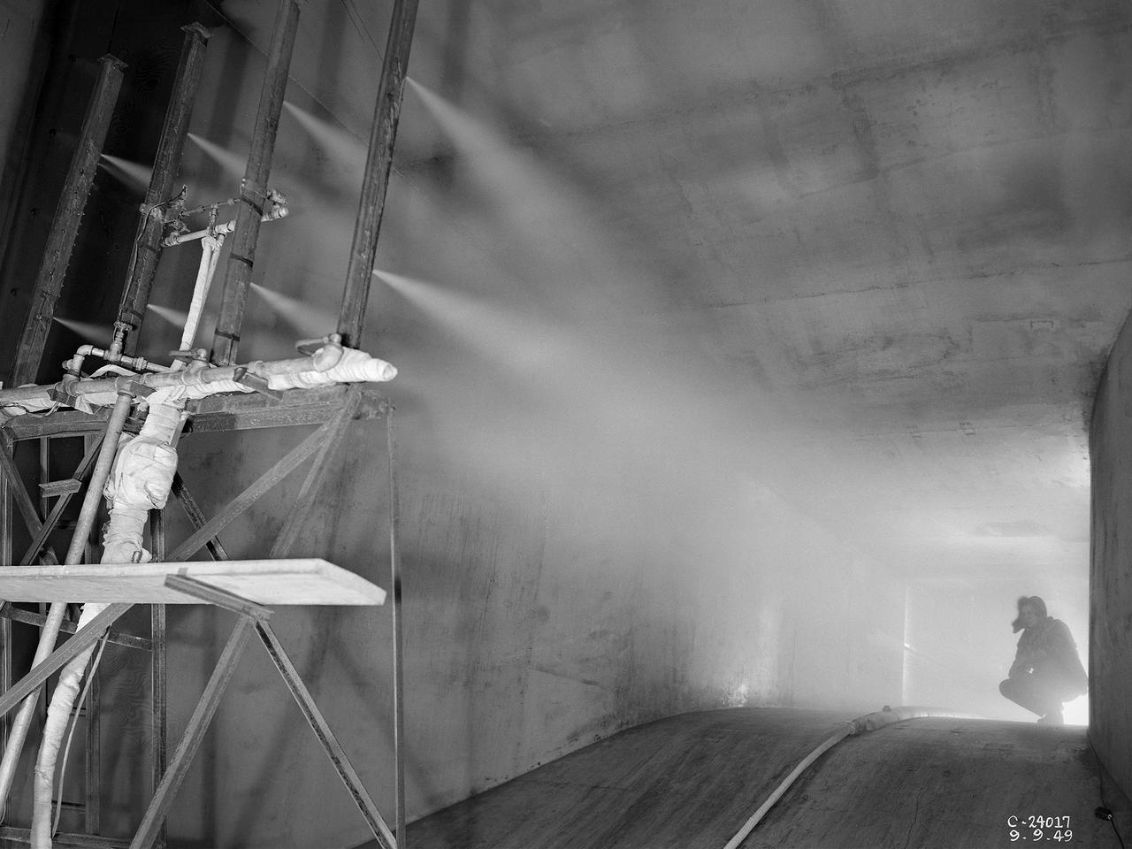
The spray bar system introduces water droplets into the Icing Research Tunnel’s air stream at the National Advisory Committee for Aeronautics (NACA) Lewis Flight Propulsion Laboratory. The icing tunnel was designed in the early 1940s to study ice accretion on airfoils and models. The Carrier Corporation designed a refrigeration system that reduced temperatures to -45° F. The tunnel’s drive fan generated speeds up to 400 miles per hour. The uniform injection of water droplets to the air was a key element of the facility’s operation. The system had to generate small droplets, distribute them uniformly throughout the airstream, and resist freezing and blockage. The Icing Research Tunnel’s designers struggled to develop a realistic spray system because they did not have access to data on the size of naturally occurring water droplets. For five years a variety of different designs were painstakingly developed and tested before the system was perfected. This photograph shows one of the trials using eight air-atomizing nozzles placed 48 feet upstream from the test section. A multi-cylinder device measured the size, liquid content, and distribution of the water droplets. The final system that was put into operation in 1950 included six horizontal spray bars with 80 nozzles that produced a 4- by 4-foot cloud in the test section. The Icing Research Tunnel produced excellent data throughout the 1950s and provided the basis for a hot air anti-icing system used on many transport aircraft.

Particle-image velocimetry (PIV) is performed on the upper surface of a pitching airfoil in the NASA Glenn Icing Research Tunnel. PIV is a laser-based flow velocity measurement technique used widely in wind tunnels. These experiments were conducted as part of a research project focused on enhancing rotorcraft speed, efficiency and maneuverability by suppressing dynamic stall.
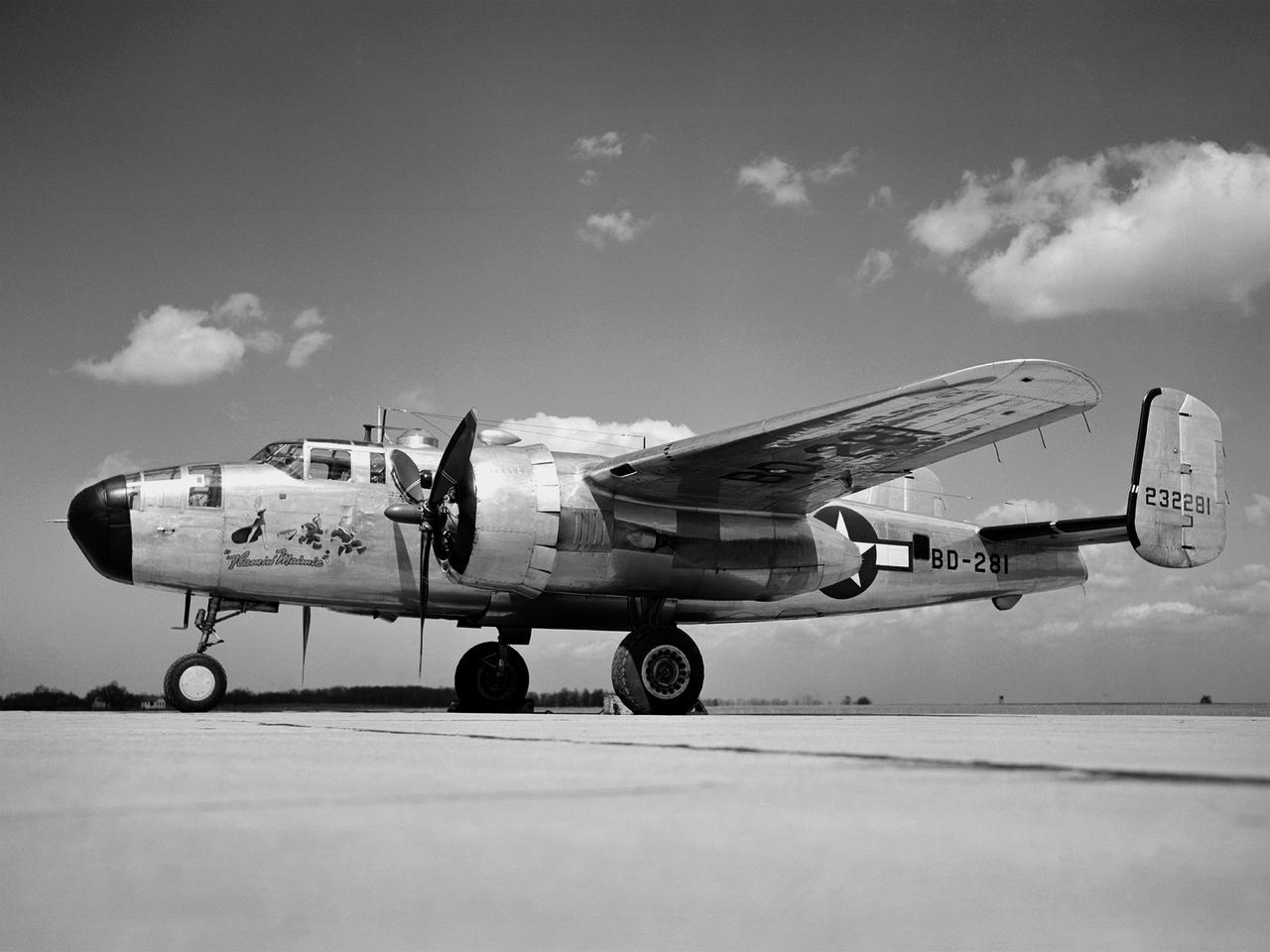
In 1946 the Lewis Flight Propulsion Laboratory became the NACA’s official icing research center. In addition to the Icing Research Tunnel, the lab possessed several aircraft modified for icing work, including a Consolidated B-24M Liberator and a North American XB-25E Mitchell, seen here. The XB-25E’s frequent engine fires allegedly resulted in its “Flamin’ Maimie” nickname. The aircraft’s nose art, visible in this photograph, includes a leather-jacketed mechanic with an extinguisher fleeing a fiery woman. North American developed the B-25 in the mid-1930s as a transport aircraft, but it was hurriedly reconfigured as a medium bomber for World War II. This XB-25E was a single prototype designed in 1942 specifically to test an exhaust gas ice prevention system developed by NACA researcher Lewis Rodert. The system circulated the engines’ hot bleed air to the wings, windshield, and tail. The XB-25E was utilized at the NACA’s Ames Aeronautical Laboratory for two years before being transferred to Cleveland in July 1944. NACA Lewis mechanics modified the aircraft further by installing electrical heating in the front fuselage, propellers, inboard sing, cowls, and antennae. Lewis pilots flew the B-24M and XB-25E into perilous weather conditions all across the country to study both deicing technologies and the physics of ice-producing clouds. These dangerous flights led to advances in weather sensing instruments and flight planning.
![NASA researchers have new [sic] insights into the mysteries of Arctic sea ice, thanks to the unique abilities of Canada Radarsat satellite.](https://images-assets.nasa.gov/image/PIA02971/PIA02971~thumb.jpg)
NASA researchers have new [sic] insights into the mysteries of Arctic sea ice, thanks to the unique abilities of Canada Radarsat satellite.
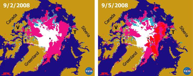
There has been considerable interest in the recent state of Arctic sea ice for scientific research and for operational applications especially along the Northern Sea Route and the Northwest Passage.
![NASA researchers have new [sic] insights into the mysteries of Arctic sea ice, thanks to the unique abilities of Canada's Radarsat satellite. The Arctic is the smallest of the world's four oceans, but it may play a large role in helping scientists monitor Earth's climate shifts. Using Radarsat's special sensors to take images at night and to peer through clouds, NASA researchers can now see the complete ice cover of the Arctic. This allows tracking of any shifts and changes, in unprecedented detail, over the course of an entire winter. The radar-generated, high-resolution images are up to 100 times better than those taken by previous satellites. http://photojournal.jpl.nasa.gov/catalog/PIA02970](https://images-assets.nasa.gov/image/PIA02970/PIA02970~thumb.jpg)
NASA researchers have new [sic] insights into the mysteries of Arctic sea ice, thanks to the unique abilities of Canada's Radarsat satellite. The Arctic is the smallest of the world's four oceans, but it may play a large role in helping scientists monitor Earth's climate shifts. Using Radarsat's special sensors to take images at night and to peer through clouds, NASA researchers can now see the complete ice cover of the Arctic. This allows tracking of any shifts and changes, in unprecedented detail, over the course of an entire winter. The radar-generated, high-resolution images are up to 100 times better than those taken by previous satellites. http://photojournal.jpl.nasa.gov/catalog/PIA02970
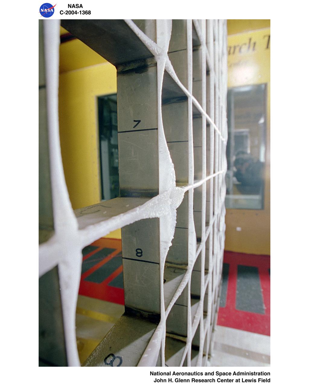
Icing Research Tunnel's icing grid with super-cooled large droplet (SLD) icing conditions
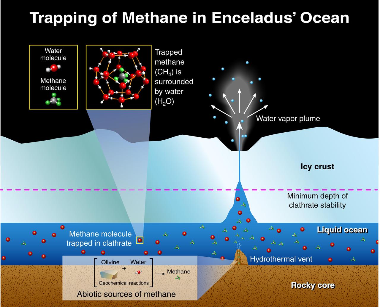
This illustration depicts potential origins of methane found in the plume of gas and ice particles that sprays from Saturn moon, Enceladus, based on research by scientists working with the Ion and Neutral Mass Spectrometer on NASA Cassini mission.
De-icing Research conducted at the NASA Ames Research Center. Icing flight test on C-46 airplane (flight 29 11:25am to 12:50 am) glaze ice on loop antenna co-pilots airspeed mast.
Common Research Model, CRM, in the Icing Research Tunnel, IRT
Common Research Model, CRM, in the Icing Research Tunnel, IRT
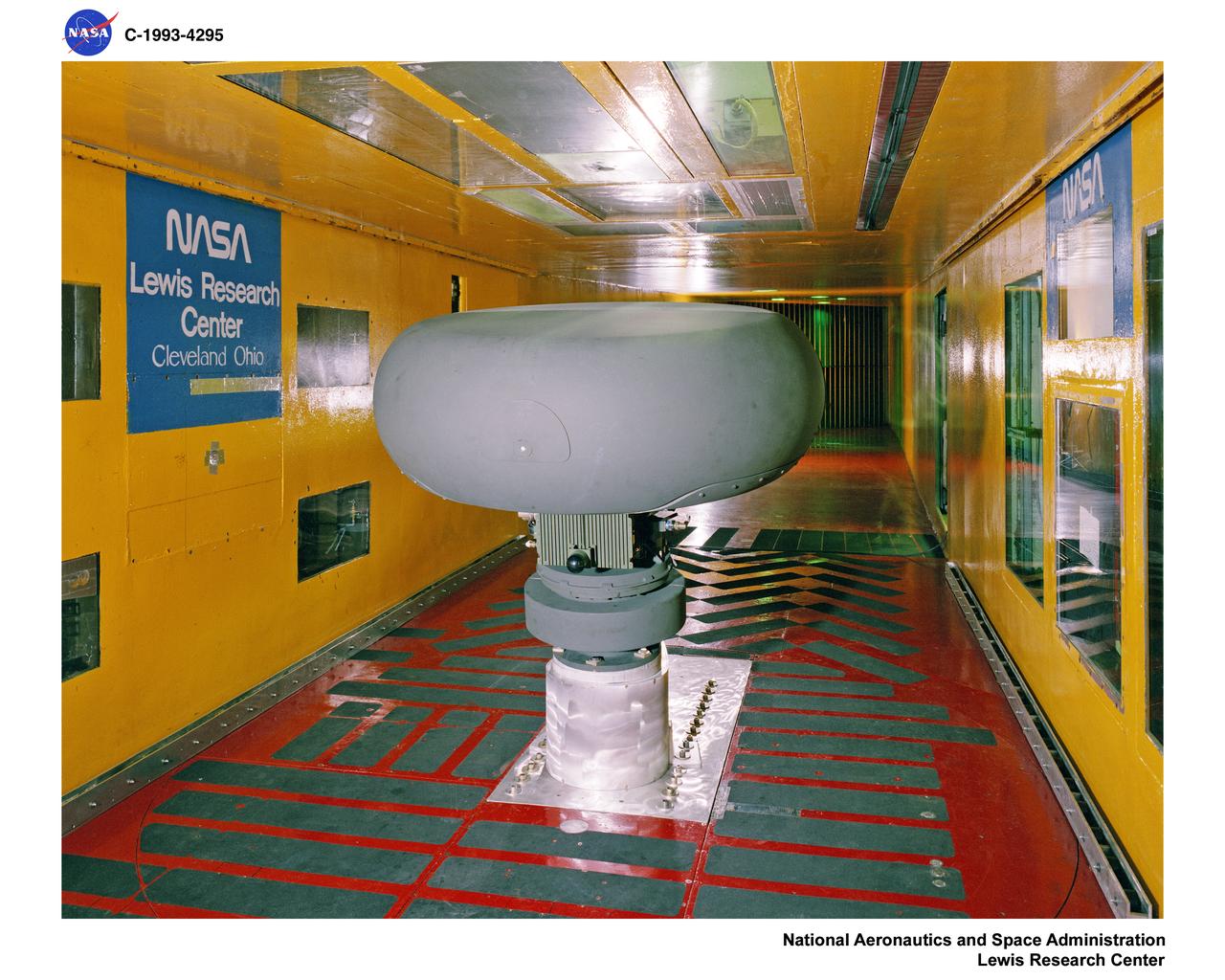
THE LONGBOW MODEL IN THE ICING RESEARCH TUNNEL
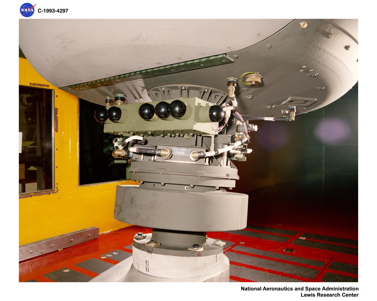
THE LONGBOW MODEL IN THE ICING RESEARCH TUNNEL
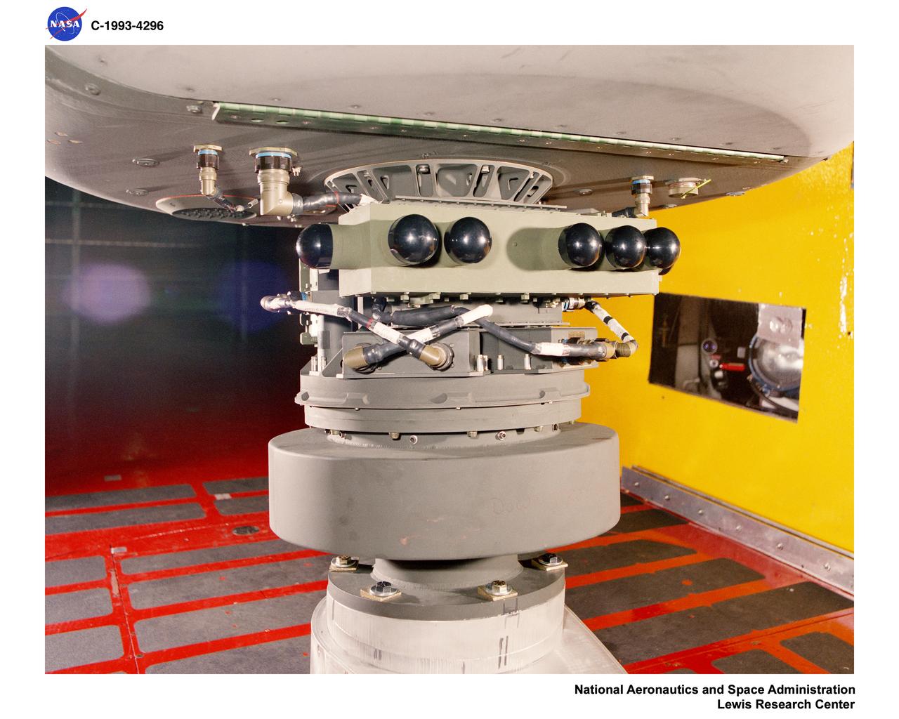
THE LONGBOW MODEL IN THE ICING RESEARCH TUNNEL
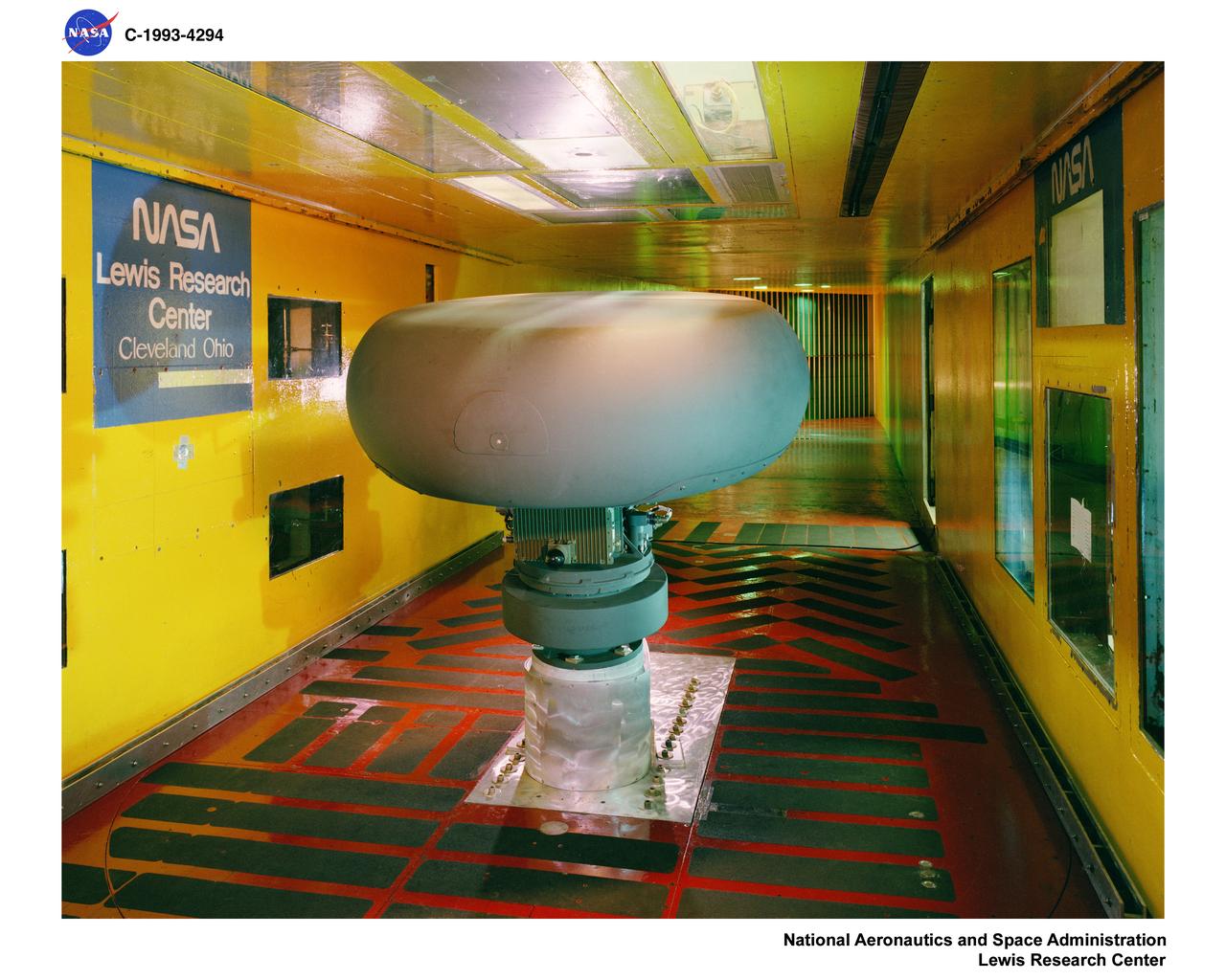
THE LONGBOW MODEL IN THE ICING RESEARCH TUNNEL
Hardware Shoot in the Icing Research Tunnel
Model in the Icing Research Tunnel, IRT
A National Advisory Committee for Aeronautics (NACA) researcher measures the ice thickness on a landing antenna model in the Icing Research Tunnel at the Aircraft Engine Research Laboratory. NACA design engineers added the Icing Research Tunnel to the original layout of the new Aircraft Engine Research Laboratory to take advantage of the massive refrigeration system being built for the Altitude Wind Tunnel. The Icing Research Tunnel was built to study the formation of ice on aircraft surfaces and methods of preventing or eradicating that ice. Ice buildup adds extra weight, effects aerodynamics, and sometimes blocks air flow through engines. The Icing Research Tunnel is a closed-loop atmospheric wind tunnel with a 6- by 9-foot test section. Carrier Corporation refrigeration equipment reduced the internal air temperature to -45 degrees F and a spray bar system injected water droplets into the air stream. The 24-foot diameter drive fan, seen in this photograph, created air flows velocities up to 400 miles per hour. The Icing Research Tunnel began testing in June of 1944. Early testing, seen in this photograph, studied ice accumulation on propellers and antenna of a military aircraft. The Icing Research Tunnel’s designers, however, struggled to develop a realistic spray system since they did not have access to data on the size of naturally occurring water droplets. The system would have to generate small droplets, distribute them uniformly throughout the airstream, and resist freezing and blockage. For five years a variety of different designs were painstakingly developed and tested before the system was perfected.
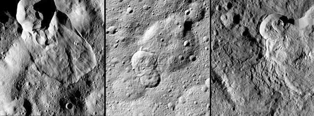
NASA's Dawn spacecraft has revealed many landslides on Ceres, which researchers interpret to have been shaped by a significant amount of water ice. A 2017 study in the journal Nature Geoscience classifies three types of these debris flows. Image 1 (left in the montage) shows an example of "Type I" flow features, which are relatively round and large, have thick "toes" at their ends. They look similar to rock glaciers and icy landslides on Earth. Type I landslides are mostly found at high latitudes, which is also where the most ice is thought to reside near Ceres' surface. Image 2 (center) shows an example of a "Type II" flow feature. Type II features are often thinner and longer than Type I, and are the most common type of landslide on Ceres. They appear more like the avalanches seen on Earth. Image 3 (right) shows an example of a "Type III" flow feature at Datan Crater. The study authors interpret Ceres' Type III landslides to involve melted ice, although scientists do not know if they actually contain liquid water. The authors think Type III landslides are related to impact craters, and may have formed during impact events into the ice on Ceres. The features resemble fluid material ejected from craters in the icy regions of Mars and Jupiter's moon Ganymede. https://photojournal.jpl.nasa.gov/catalog/PIA21471
IMPINGEMENT TEST IN ICING RESEARCH TUNNEL IRT
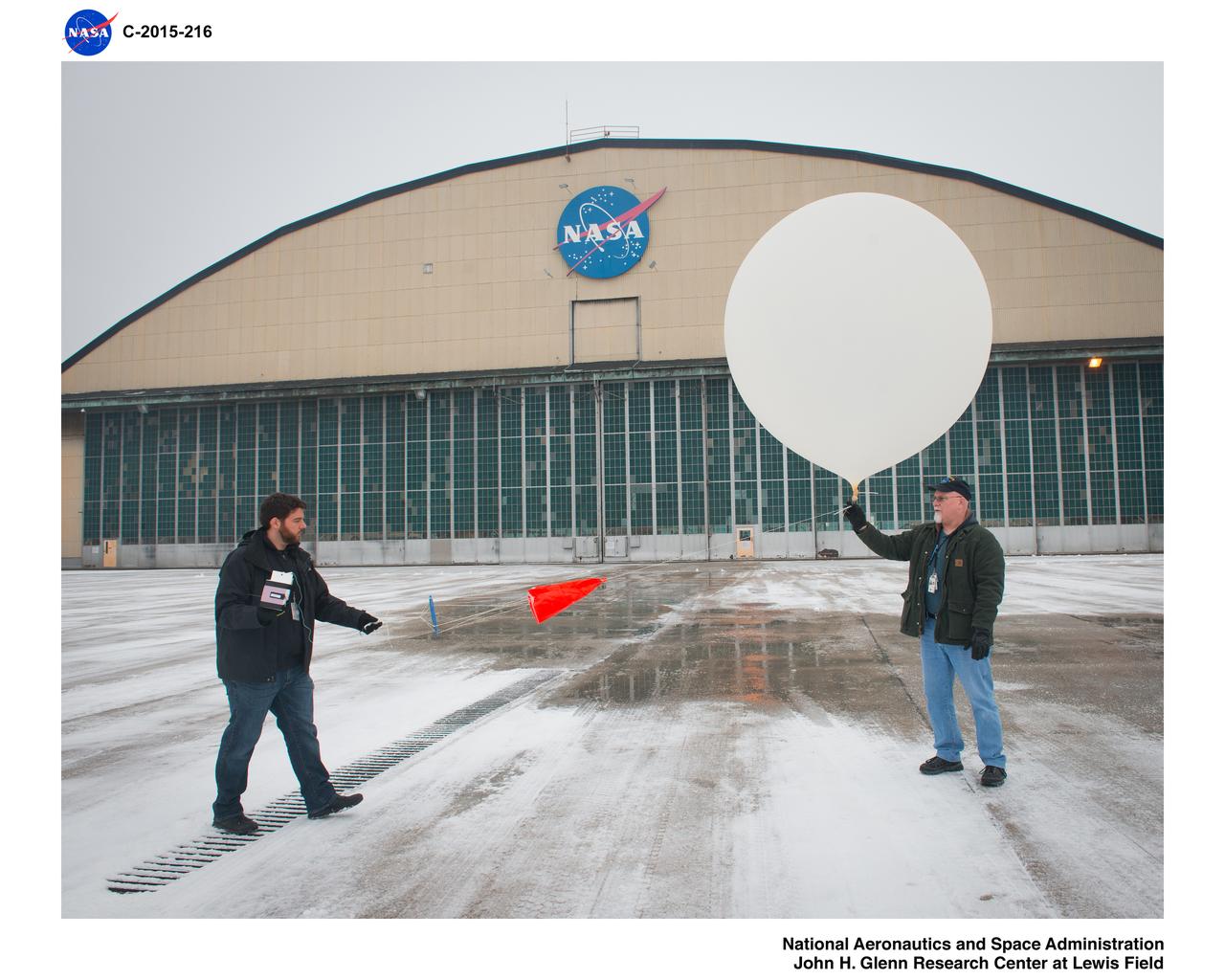
Glenn Weather Balloon Icing Research Activities
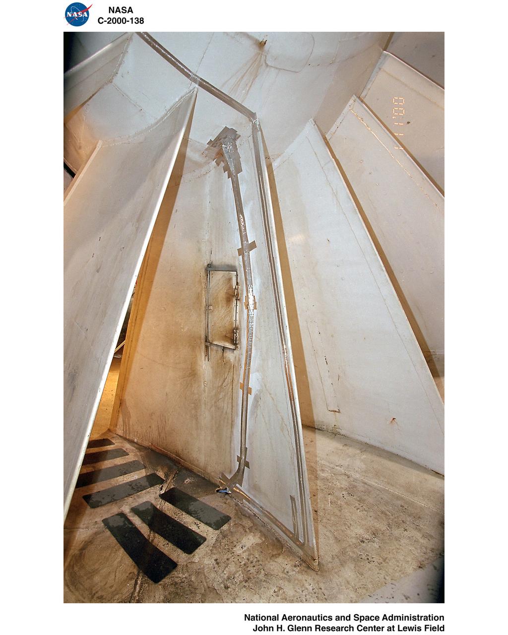
Icing Research Tunnel (IRT) "AB Corner" Rehabilitation
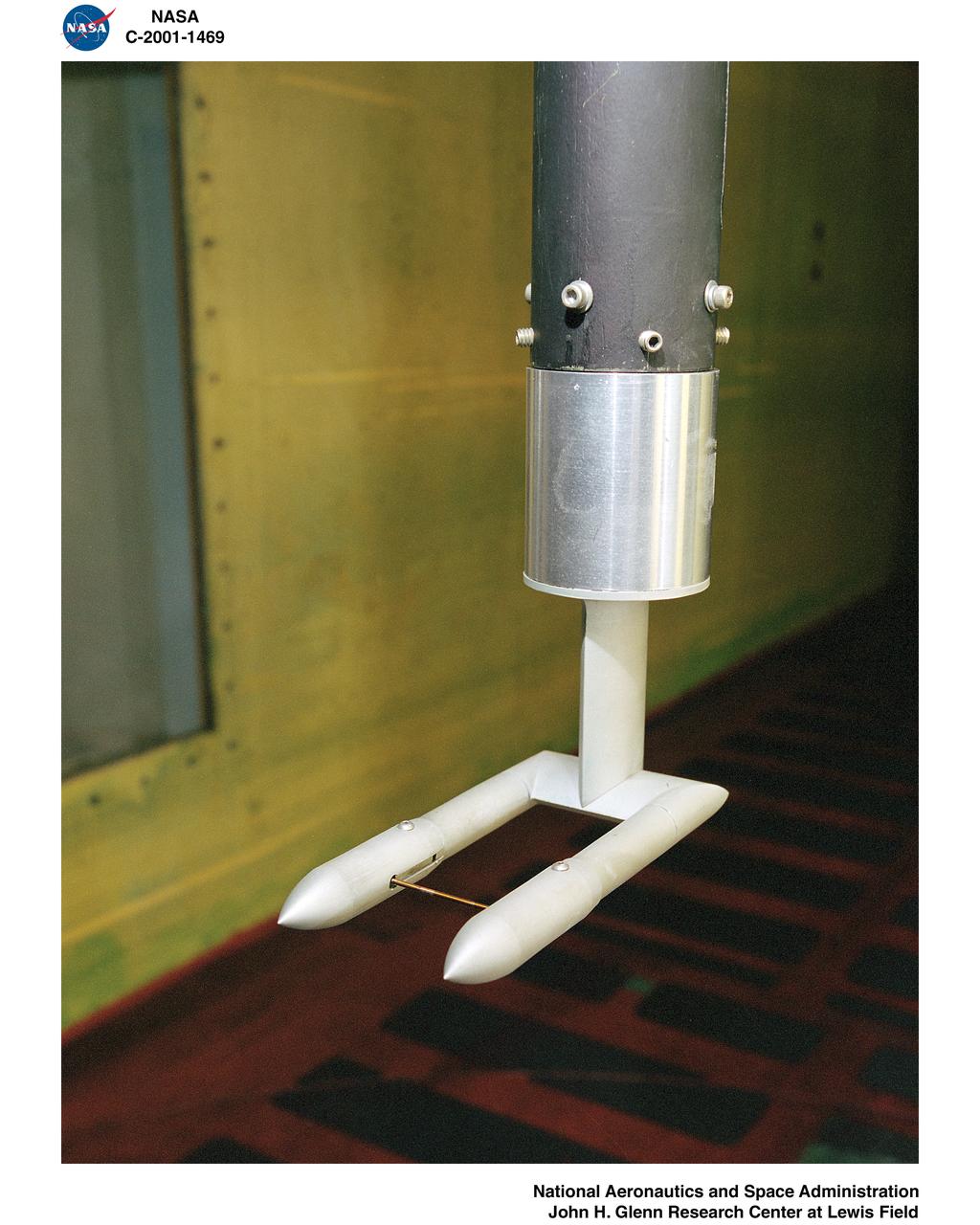
IRT - ICING RESEARCH TUNNEL WAKE SURVEY PROBE
IMPINGEMENT TEST IN ICING RESEARCH TUNNEL IRT
INSTRUMENTATION COMPARISON HARDWARE IN ICING RESEARCH TUNNEL IRT
Icing Research Tunnel (IRT) "AB Corner" Rehabilitation
Common Research Model, CRM, in the Icing Research Tunnel, IRT, Installation of Test Hardware
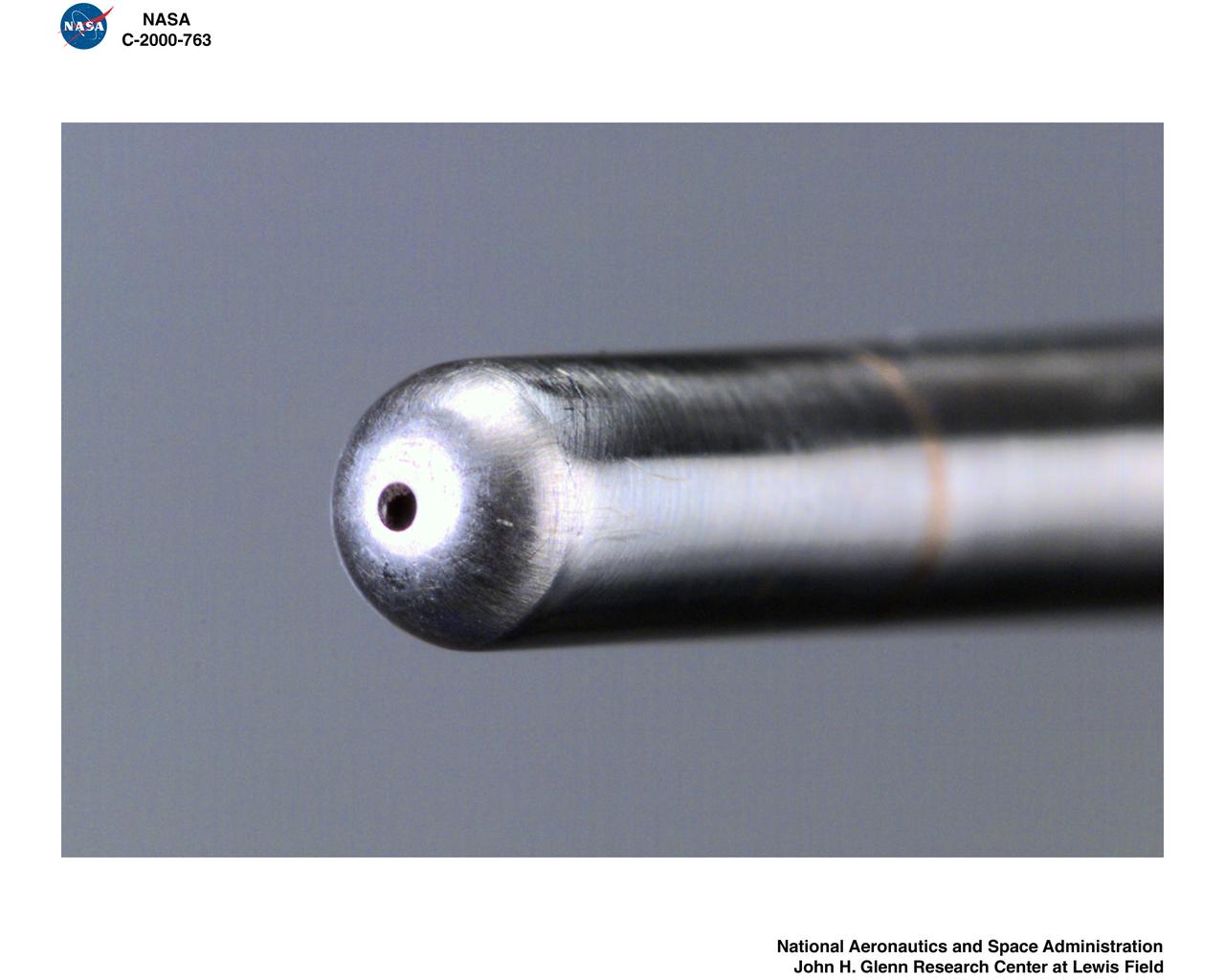
Isokinetic and Multi Wire Probes in the Icing Research Tunnel, IRT, Test Section
THERMAL CODE I TEST HARDWARE IN ICING RESEARCH TUNNEL IRT

WICHITA STATE UNIVERSITY / ICING RESEARCH TUNNEL IMPINGMENT DYE TEST
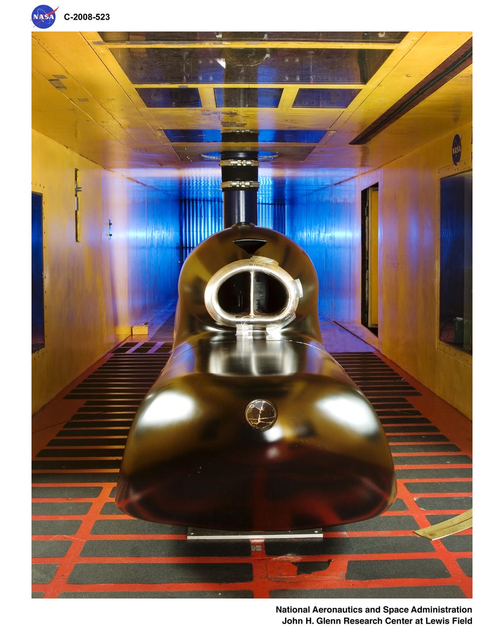
General Atomics - Predator B Inlet Model in the Icing Research Tunnel
General Electric Aviation - Engine Splitter Booster Model in the Icing Research Tunnel

WICHITA STATE UNIVERSITY / ICING RESEARCH TUNNEL IMPINGMENT DYE TEST
ICING RESEARCH TUNNEL IRT FORCE BALANCE CALIBRATION HARDWARE
WICHITA STATE UNIVERSITY / ICING RESEARCH TUNNEL IRT DYE TEAM

WICHITA STATE UNIVERSITY / ICING RESEARCH TUNNEL IMPINGMENT DYE TEST
General Atomics - Predator B Inlet Model in the Icing Research Tunnel
WICHITA STATE UNIVERSITY / ICING RESEARCH TUNNEL IMPINGMENT DYE TEST
THERMAL CODE I TEST HARDWARE IN ICING RESEARCH TUNNEL IRT
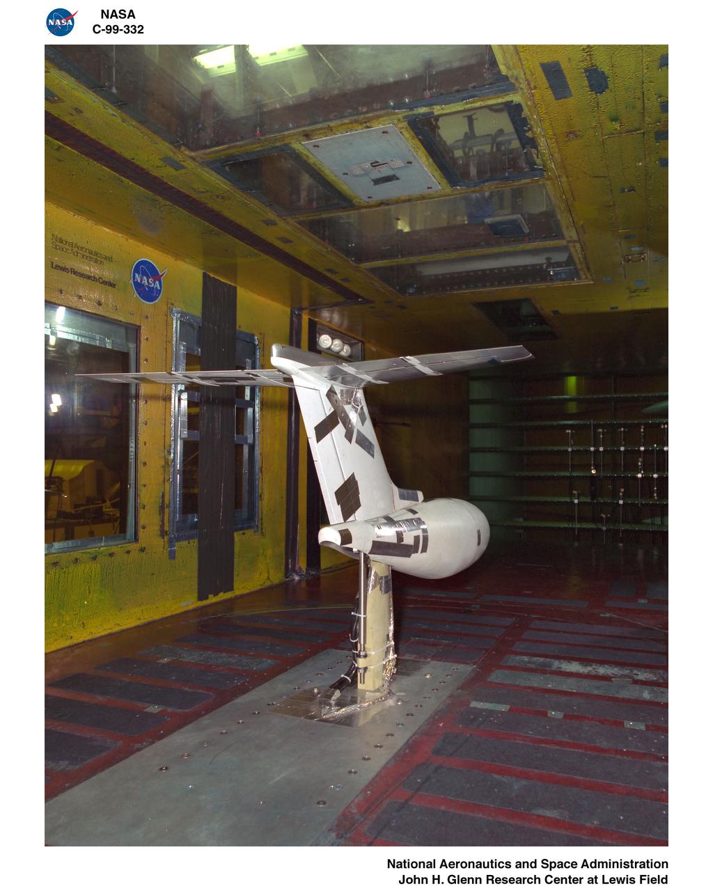
S-3 Viking 1/3 Wing Section in the Icing Research Tunnel
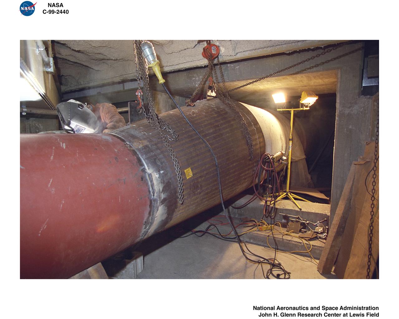
1999 CONSTRUCTION OF FACILITY ICING RESEARCH TUNNEL IRT HEAT EXCHANGER REPLACEMENT
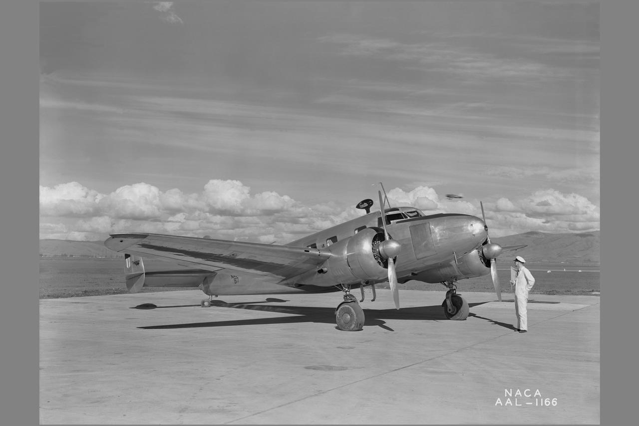
NACA photographer Lockheed 12A icing research airplane: with heated wings
1999 CONSTRUCTION OF FACILITY ICING RESEARCH TUNNEL IRT HEAT EXCHANGER REPLACEMENT

Icing Research Tunnel (IRT) Expansion Addition Construction Documentation
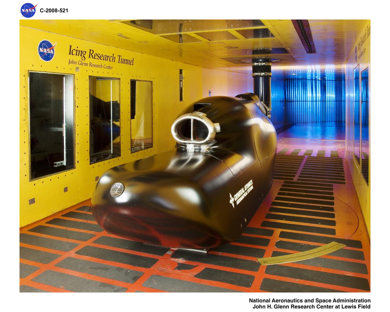
General Atomics - Predator B Inlet Model in the Icing Research Tunnel
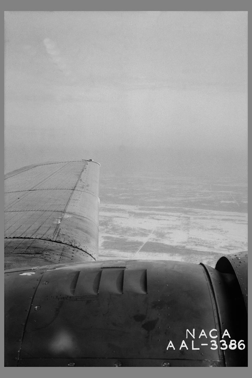
Minneapolis Ice research project: Ice formation on left wing of the Lockheed 12-A during flight after shutting off heat. The wind was completely cleared within 2 minutes after the application of heat.
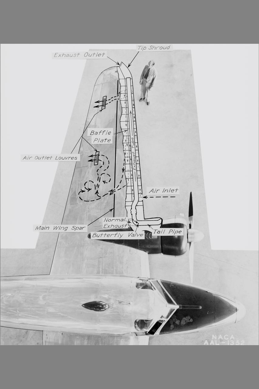
NACA Photographer NASA Ames De-icing project: diagram of the systems using exhaust-heated air to prevent icing on the Lockheed 12A wings Published: Adventures in Research SP-4302

Clark University's Luke Trusel works amid sea ice in the Chukchi Sea on July 9, 2010, and logs the depths at which measurements are collected below the ice. The research is part of NASA's ICESCAPE mission to sample the physical, chemical and biological characteristics of the ocean and sea ice. Impacts of Climate change on the Eco-Systems and Chemistry of the Arctic Pacific Environment (ICESCAPE) is a multi-year NASA shipborne project. The bulk of the research will take place in the Beaufort and Chukchi Sea’s in summer of 2010 and fall of 2011. Photo Credit: (NASA/Kathryn Hansen)
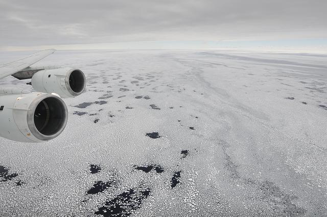
Sea ice is seen out the window of NASA's DC-8 research aircraft as it flies 2,000 feet above the Bellingshausen Sea in West Antarctica on Wednesday, Oct., 21, 2009. This was the fourth science flight of NASA’s Operation Ice Bridge airborne Earth science mission to study Antarctic ice sheets, sea ice, and ice shelves. Photo Credit: (NASA/Jane Peterson)
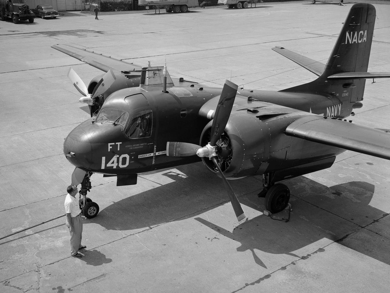
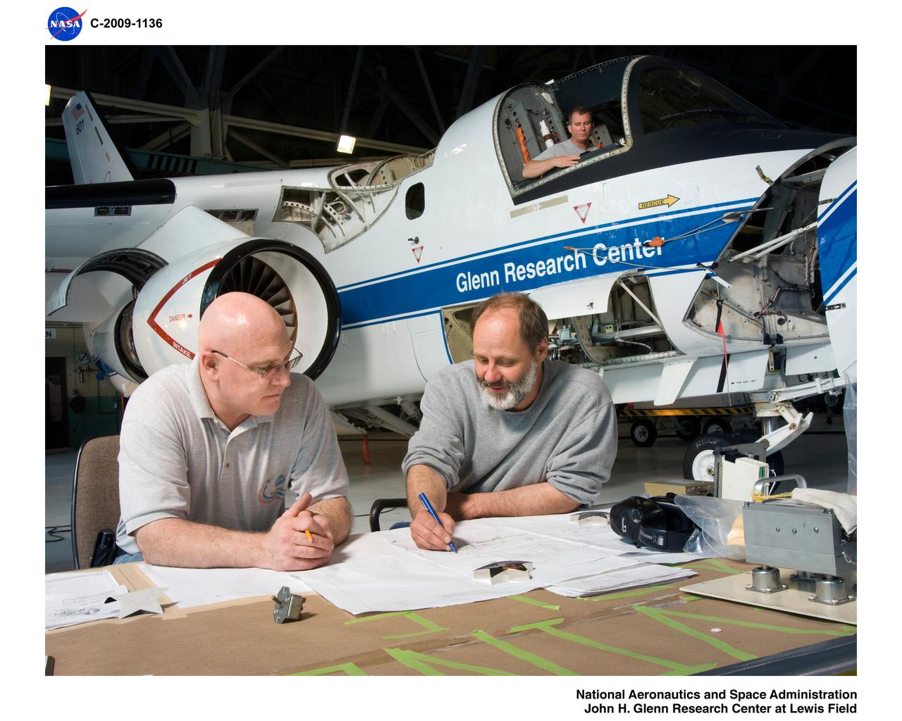
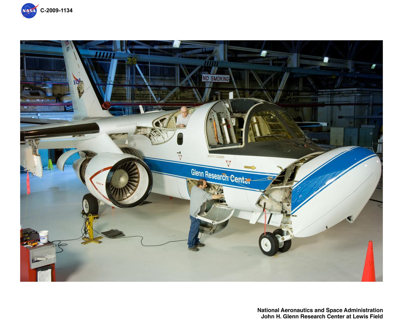
The NACA’s Lewis Flight Propulsion Laboratory acquired the Grumman S2F-1 Tracker from the Navy in 1955 to study icing instrumentation. Lewis’s icing research program was winding down at the time. The use of jet engines was increasing thus reducing the threat of ice accumulation. Nonetheless Lewis continued research on the instrumentation used to detect icing conditions. The S2F-1 Tracker was a carrier-based submarine hunter for the Navy. Grumman developed the Tracker as a successor to its Korean War-era Guardian patrol aircraft. Prototypes first flew in late 1952 and battle-ready versions entered Naval service in early 1954. The Navy utilized the Trackers to protect fleets from attack.
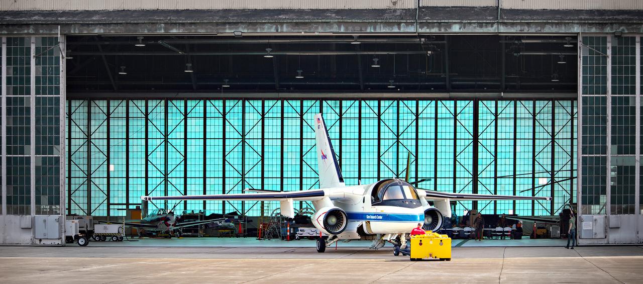
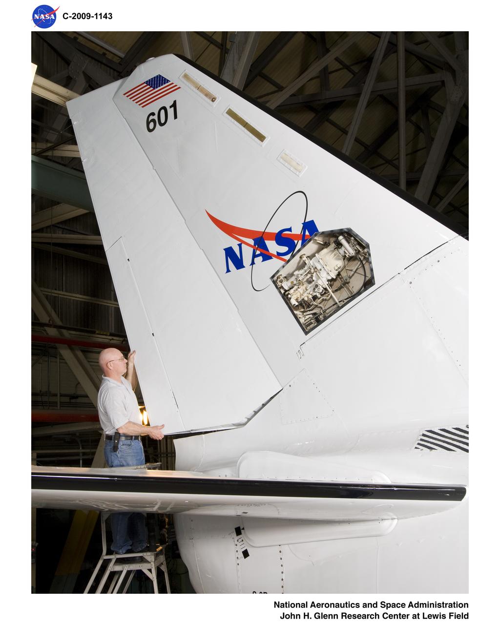
The Lockheed Viking S-3B aircraft is being pulled out of the hangar at Glenn Research Center in preparation for its departure and retirement from service. This former NAVY aircraft was the last such aircraft still flying. It has gone to a museum on the west coast. After leaving service with the NAVY, it came to GRC to be used in aircraft icing experiments. The swept wings made it suitable for such research as opposed to the straight wings on GRG’s other icing research aircraft, the De Havilland Twin Otter.
Lockheed Martin S-3B Viking Aircraft #N601NA, Preparation for Icing Research Instrumentation Installation
Icing Physics Flow Lab at Case Western Reserve University. Test bed in rolled out position with researcher making adjustments
Lockheed Martin S-3B Viking Aircraft #N601NA, Preparation for Icing Research Instrumentation Installation
Construction of the Icing Research Tunnel, IRT, Refrigeration Plant-Newly Installed Heat Exchanger
MWISP - MT WASHINGTON ICING SENSORS PROJECT - DR RYERSON AT CRREL - COLD REGIONS RESEARCH AND ENGINEERING LABORATORY - WORKSTATION
Lockheed Martin S-3B Viking Aircraft #N601NA, Preparation for Icing Research Instrumentation Installation
Lockheed Martin S-3B Viking Aircraft #N601NA, Preparation for Icing Research Instrumentation Installation
Lockheed Martin S-3B Viking Aircraft #N601NA, Preparation for Icing Research Instrumentation Installation
The FJ33 Engine Inlet from Williams International being tested in the Icing Research Tunnel
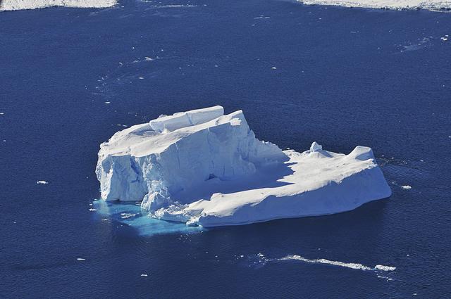
An iceberg is seen out the window of NASA's DC-8 research aircraft as it flies 2,000 feet above the Amundsen Sea in West Antarctica on Wednesday, Oct., 21, 2009. This was the fourth science flight of NASA’s Operation Ice Bridge airborne Earth science mission to study Antarctic ice sheets, sea ice, and ice shelves. Photo Credit: (NASA/Jane Peterson)
A Bell P-39 Airacobra in the NACA Aircraft Engine Research Laboratory’s Icing Research Tunnel for a propeller deicing study. The tunnel, which began operation in June 1944, was built to study the formation of ice on aircraft surfaces and methods of preventing or eradicating that ice. Ice buildup adds extra weight to aircraft, effects aerodynamics, and sometimes blocks airflow through engines. NACA design engineers added the Icing Research Tunnel to the new AERL’s original layout to take advantage of the massive refrigeration system being constructed for the Altitude Wind Tunnel. The Icing Research Tunnel is a closed-loop atmospheric wind tunnel with a 6- by 9-foot test section. The tunnel can produce speeds up to 300 miles per hour and temperatures from about 30 to -45⁰ F. During World War II AERL researchers analyzed different ice protection systems for propeller, engine inlets, antennae, and wings in the icing tunnel. The P-39 was a vital low-altitude pursuit aircraft of the US during the war. NACA investigators investigated several methods of preventing ice buildup on the P-39’s propeller, including the use of internal and external electrical heaters, alcohol, and hot gases. They found that continual heating of the blades expended more energy than the aircraft could supply, so studies focused on intermittent heating. The results of the wind tunnel investigations were then compared to actual flight tests on aircraft.
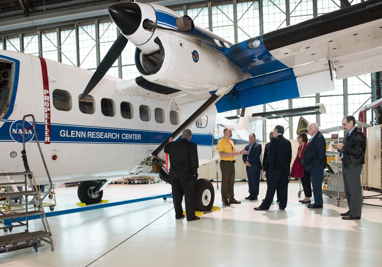
Cuyahoga County Mayors and City Managers Association Members tour the Glenn Research Center Hangar and learn about the role of the Twin Otter aircraft in the GRC Icing Research Program

Scientists on the sea ice in the Chukchi Sea off the north coast of Alaska disperse equipment on July 4, 2010, as they prepare to collect data on and below the ice. The research is part of NASA's ICESCAPE mission onboard the U.S. Coast Guard icebreaker Healy to sample the physical, chemical and biological characteristics of the ocean and sea ice. Impacts of Climate change on the Eco-Systems and Chemistry of the Arctic Pacific Environment (ICESCAPE) is a multi-year NASA shipborne project. The bulk of the research will take place in the Beaufort and Chukchi Sea’s in summer of 2010 and fall of 2011. Photo Credit: (NASA/Kathryn Hansen)

Dartmouth College's Chris Polashenski cuts a block of ice from below a melt pond on sea ice in the Chukchi Sea on July 9, 2010, for analysis upon return from the mission. The research is part of NASA's ICESCAPE mission onboard the U.S. Coast Guard icebreaker Healy to sample the physical, chemical and biological characteristics of the ocean and sea ice. Impacts of Climate change on the Eco-Systems and Chemistry of the Arctic Pacific Environment (ICESCAPE) is a multi-year NASA shipborne project. The bulk of the research will take place in the Beaufort and Chukchi Sea’s in summer of 2010 and fall of 2011. Photo Credit: (NASA/Kathryn Hansen)
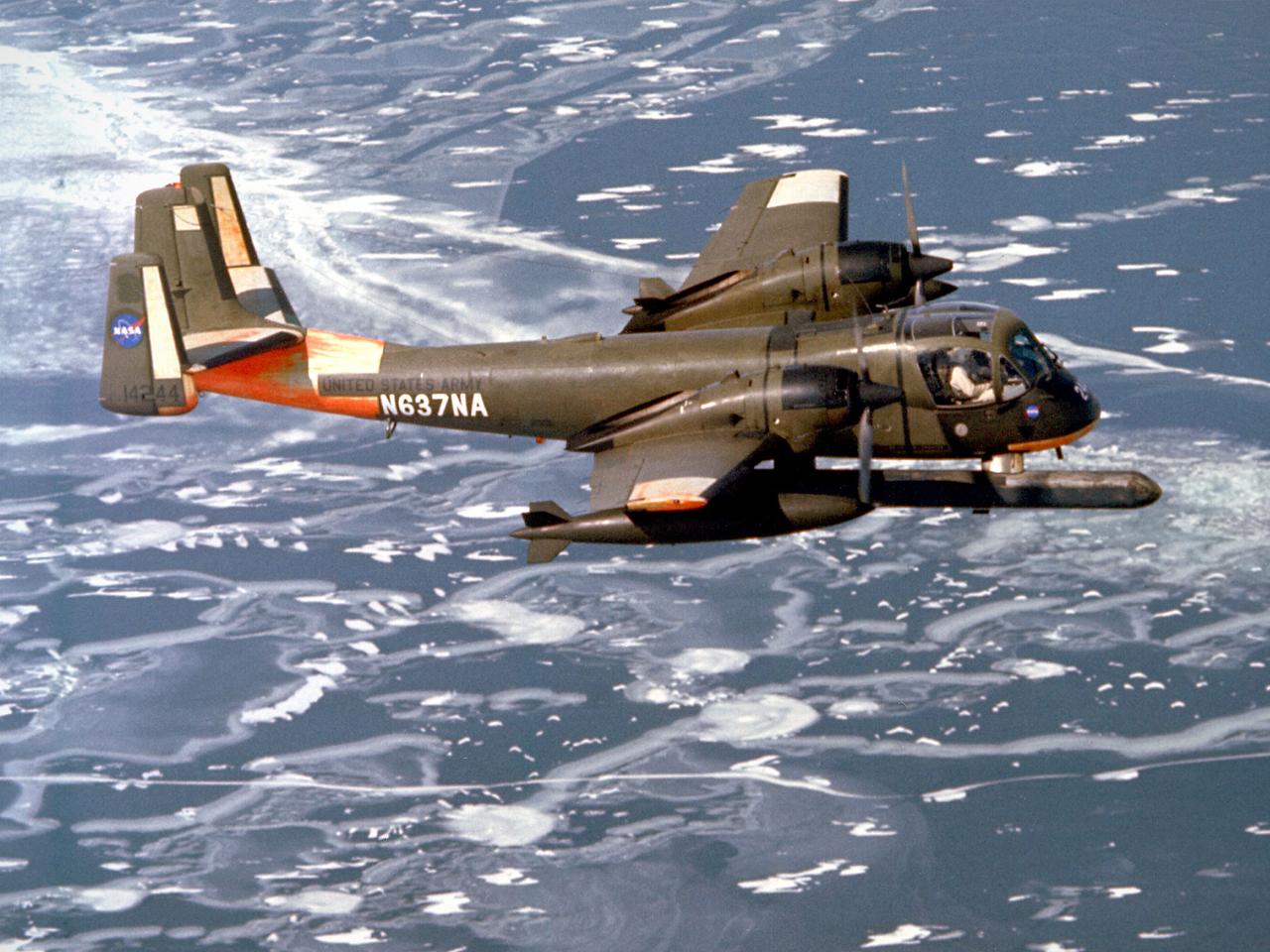
A Grumman OV-1B Mohawk maps Great Lakes’ ice flows for the National Aeronautics and Space Administration (NASA) Lewis Research Center in Cleveland, Ohio. The regular freezing of large portions of the Great Lakes during the winter frequently stalled the region’s shipping industry. Lewis developed two complementary systems to monitor the ice. The Side Looking Airborne Radar (SLAR) system used microwaves to measure the ice distribution, and electromagnetic systems employed noise modulation to determine the thickness of the ice. Once this dual system was in place, the information could be generated during a single pass of a research aircraft and quickly distributed to ship captains planning their routes. The SLAR was superior to aerial photography for this task because it was able to penetrate cloud cover. The SLAR system used pulsed microwaves to examine a band of ice or water on either side of the aircraft up to 31 miles wide. The Lewis ice mapping devices were first tested during the winter of 1972 and 1973. The system was installed on the tail of the Coast Guard’s OV-1B aircraft. An infrared thermal mapping instrument was installed on Lewis’ DC-3 to determine the ice temperature and estimate its thickness. The team created 160 ice charts that were sent to 28 ships and 2 icebreakers. Shipping was able to continue throughout the season for the first time that winter.
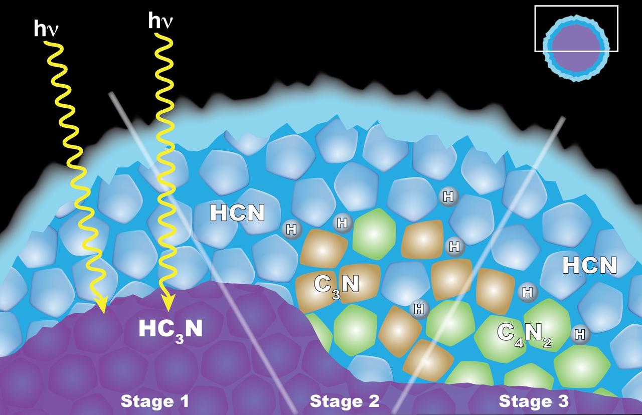
Scientists from NASA's Cassini mission suggested in a 2016 paper that the appearance of a cloud of dicyanoacetylene (C4N2) ice in Titan's stratosphere may be explained by "solid-state" chemistry taking place inside ice particles. The particles have an inner layer of cyanoacetylene (HC3N) ice coated with an outer layer of hydrogen cyanide (HCN) ice. Left: When a photon of light penetrates the outer shell, it can interact with the HC3N, producing C3N and H. Center: The C3N then reacts with HCN to yield C4N2 and H (shown at right). Another reaction that also yields C4N2 ice and H also is possible, but the researchers think it is less likely. http://photojournal.jpl.nasa.gov/catalog/PIA20715
MWISP - MT WASHINGTON ICING SENSORS PROJECT - CRREL - COLD REGIONS RESEARCH AND ENGINEERING LABORATORY - AND SPEC - STATTON PARK ENGINEERING CORPORATION PROBES

Illustration NASA Ames Research Center developed Icing Protection System: Electro-Expuisive Deicing System. (P.I. Dr Lenord Haslim)