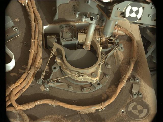
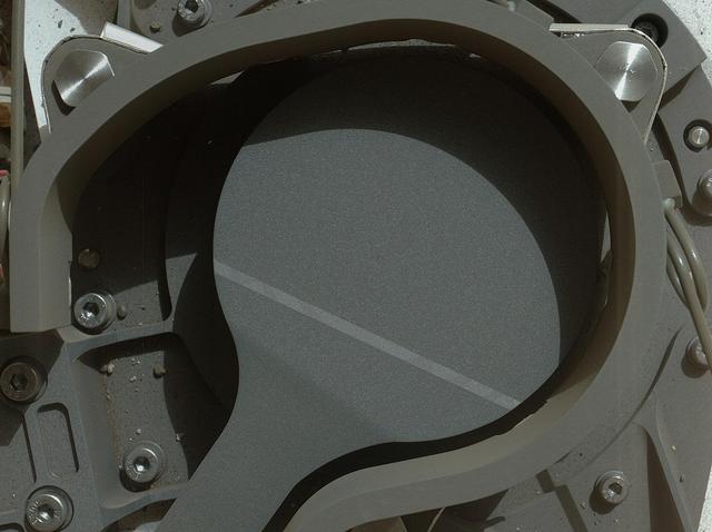
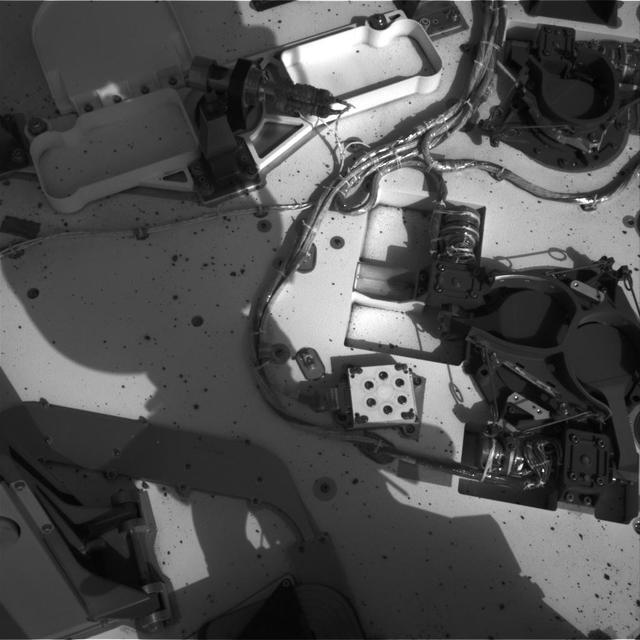
The drill bit of NASA's Curiosity Mars rover over one of the sample inlets on the rover's deck. The inlets lead to Curiosity's onboard laboratories. This image was taken on Sol 2068 by the rover's Mast Camera (Mastcam). https://photojournal.jpl.nasa.gov/catalog/PIA22327
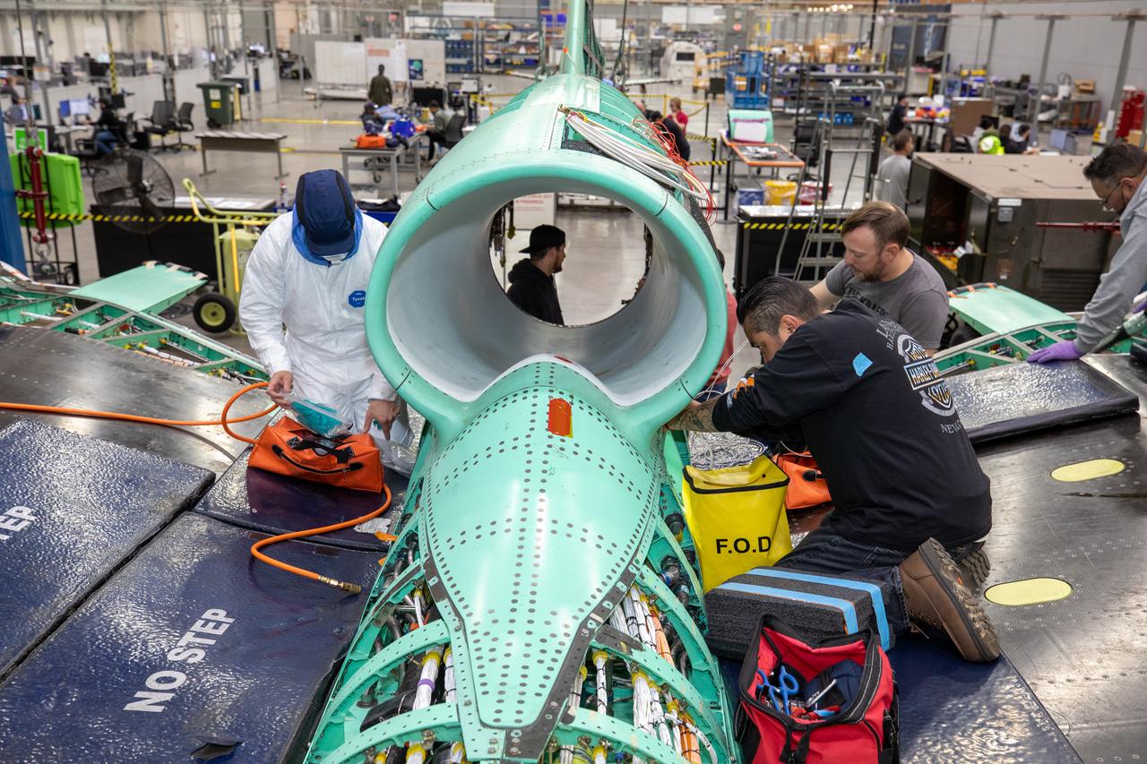
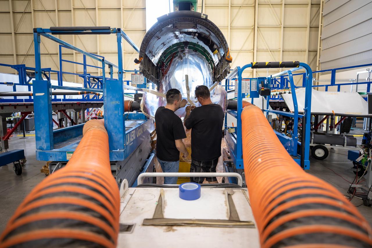
The X-59 team working on the aircraft’s wiring around the engine inlet prior to the engine being installed. Once complete, the X-59 is designed to fly supersonic while reducing the loud sonic boom. The Quesst mission could help change the rules for commercial supersonic air travel over land.
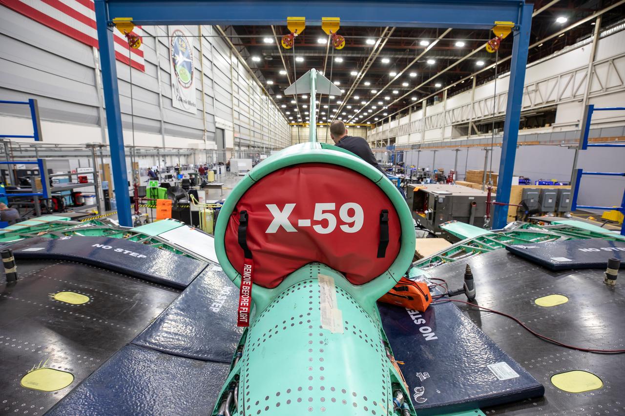
This is an image of the X-59 inlet with a safety covering. The inlet’s purpose is to adjust air speeds before they pass through the aircraft’s engine. The purpose of the covering is to protect the inlet and engine from foreign objects.
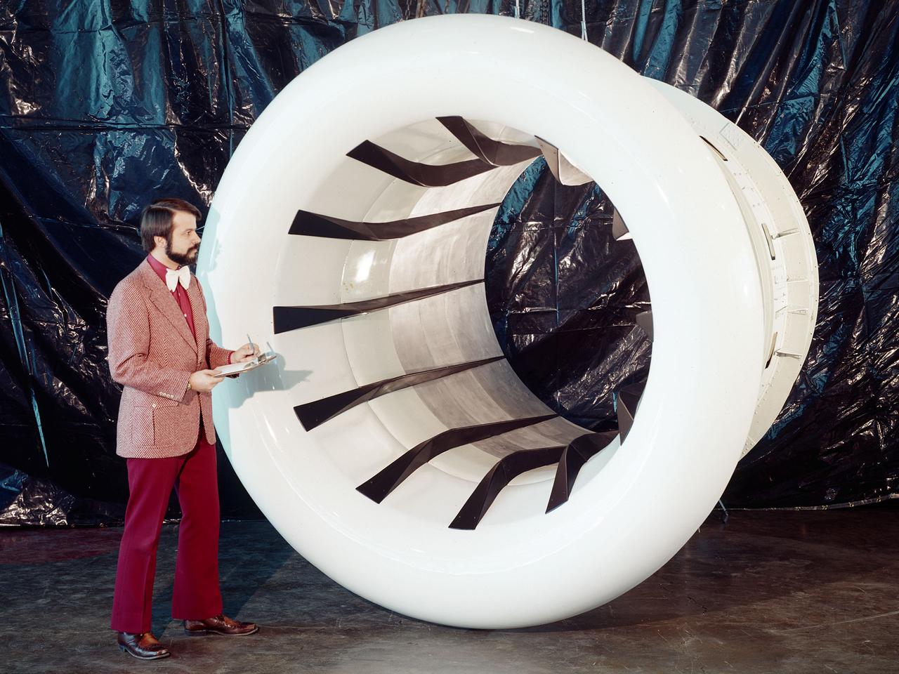
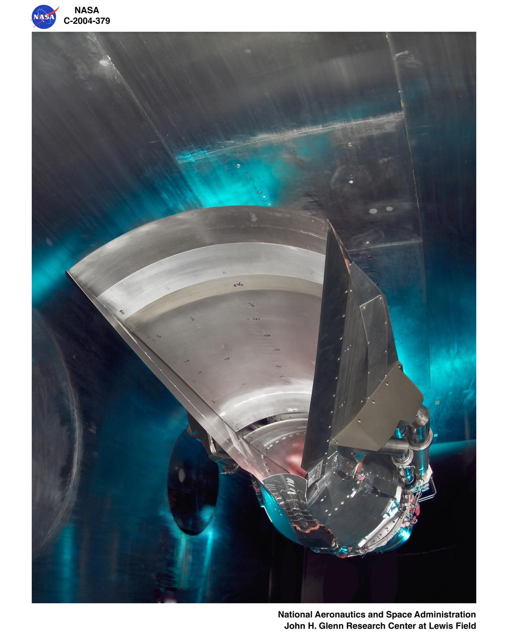
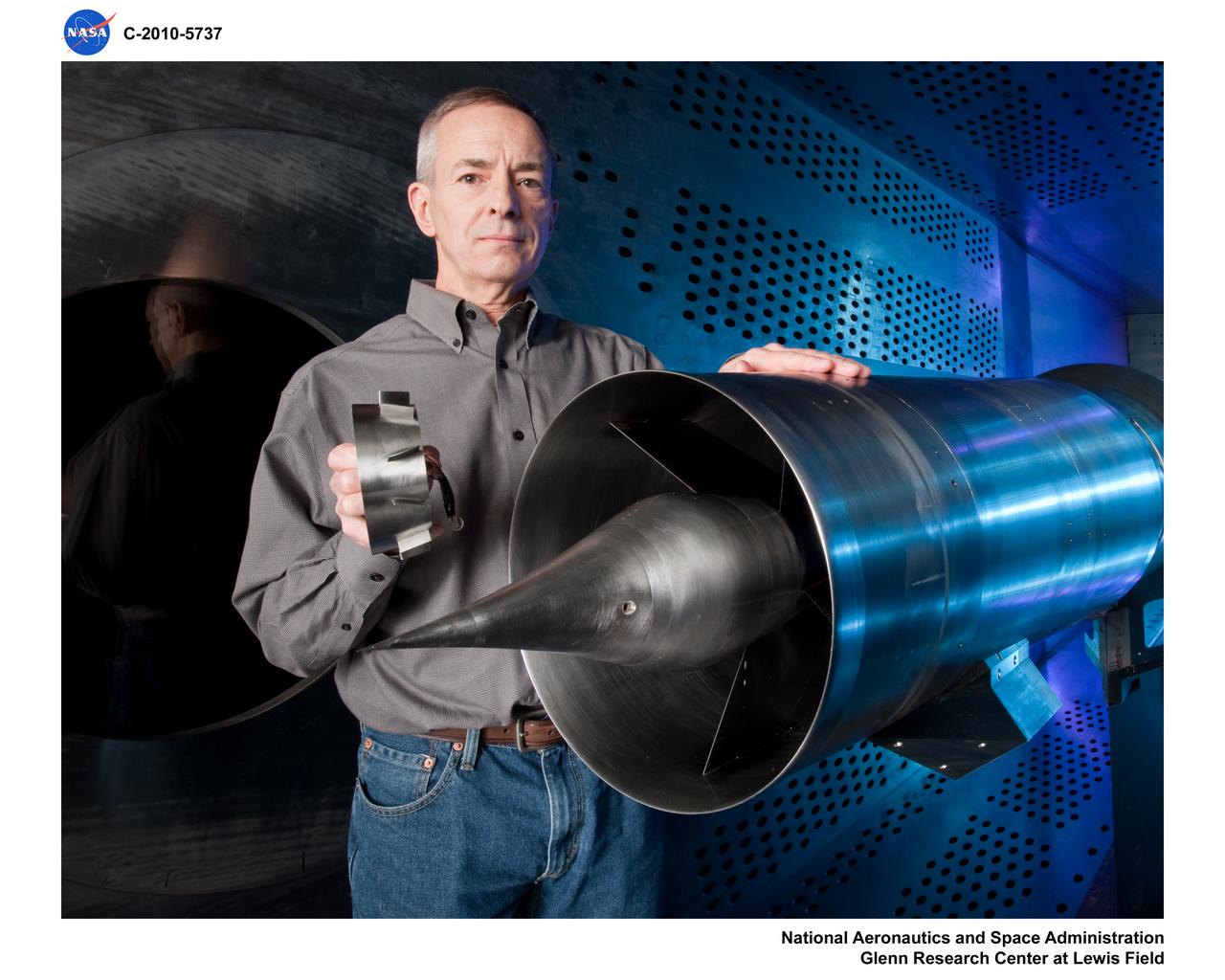
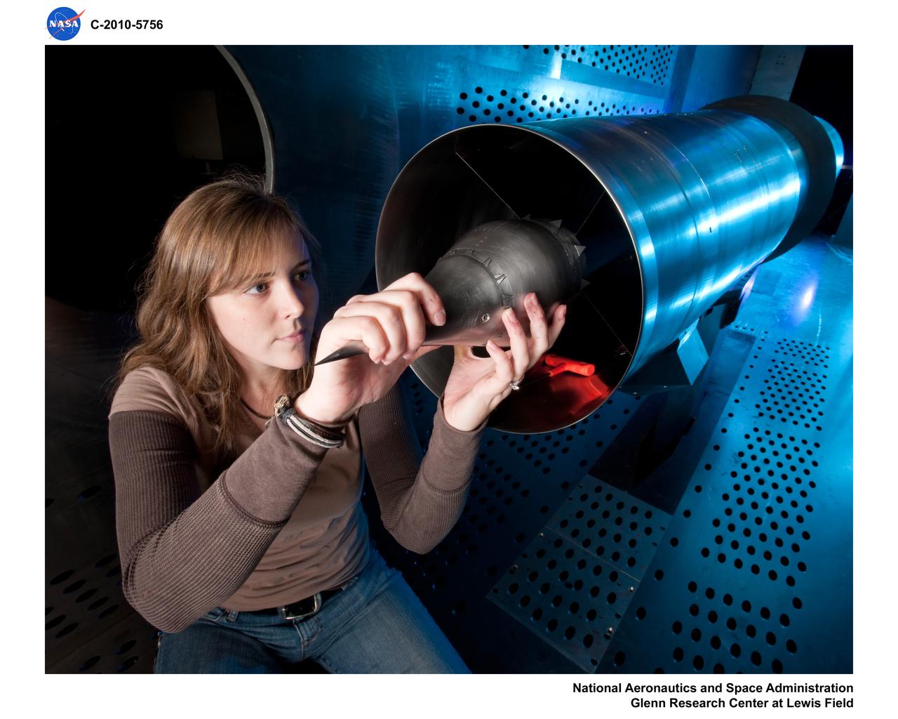
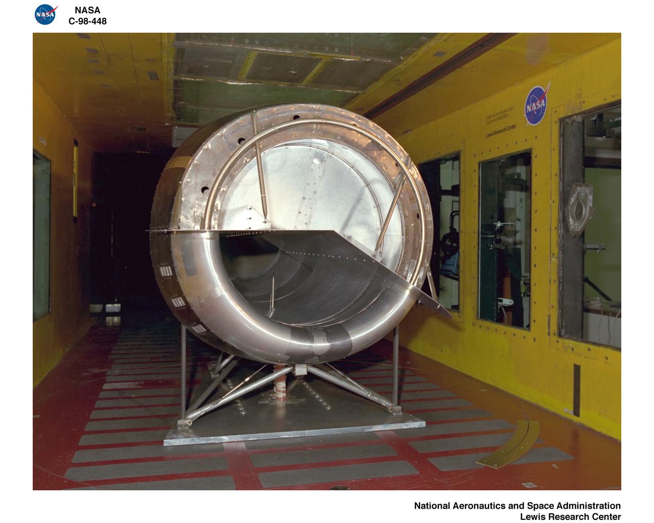
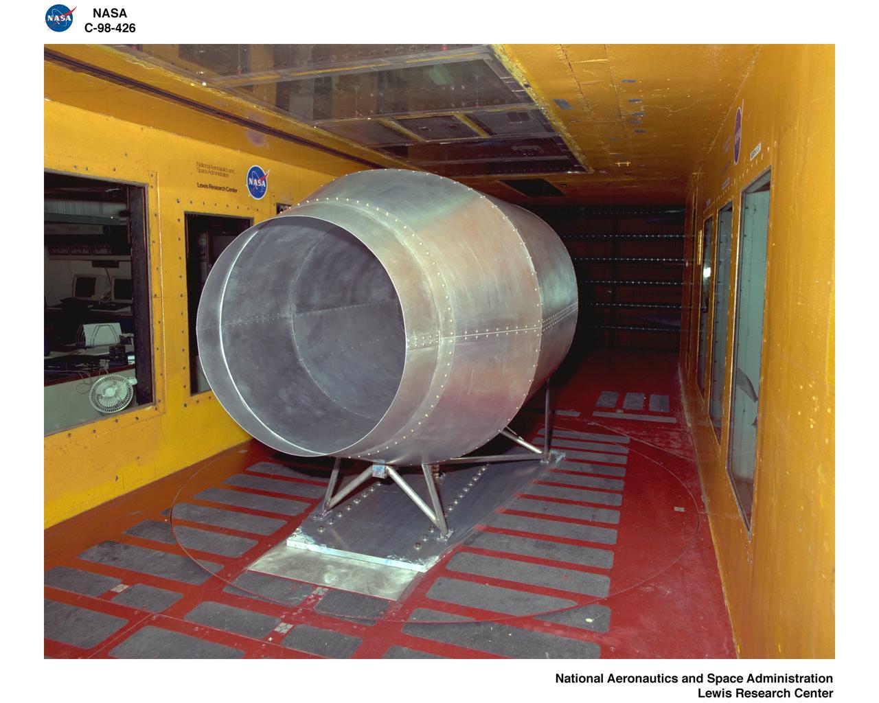
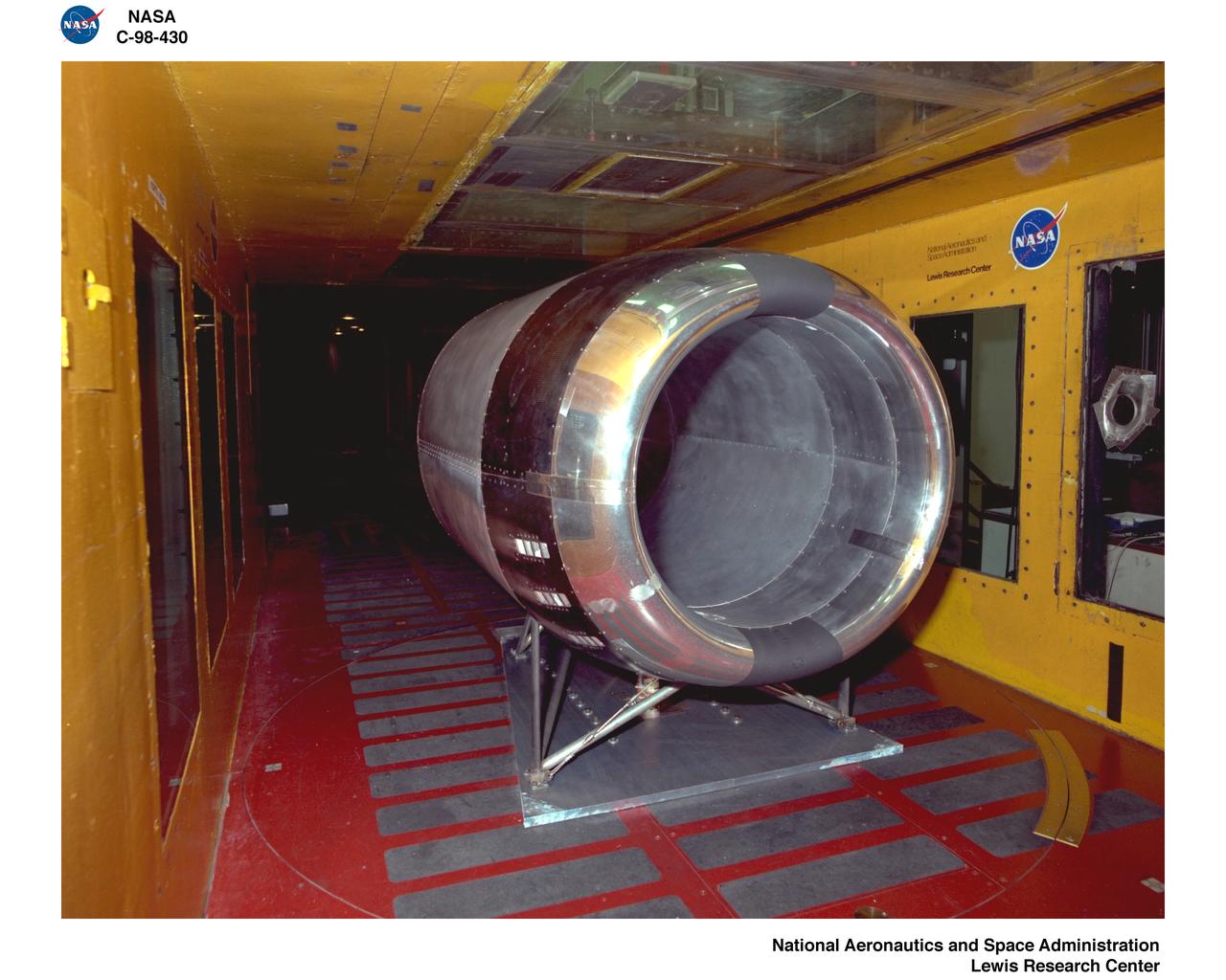
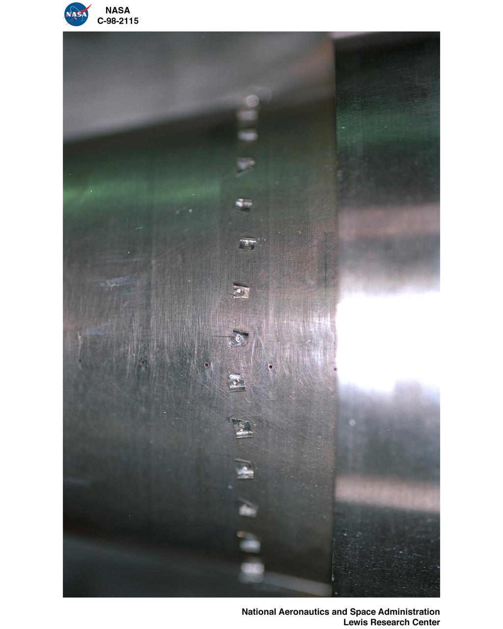
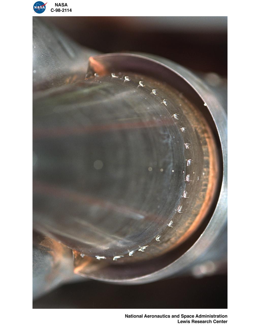
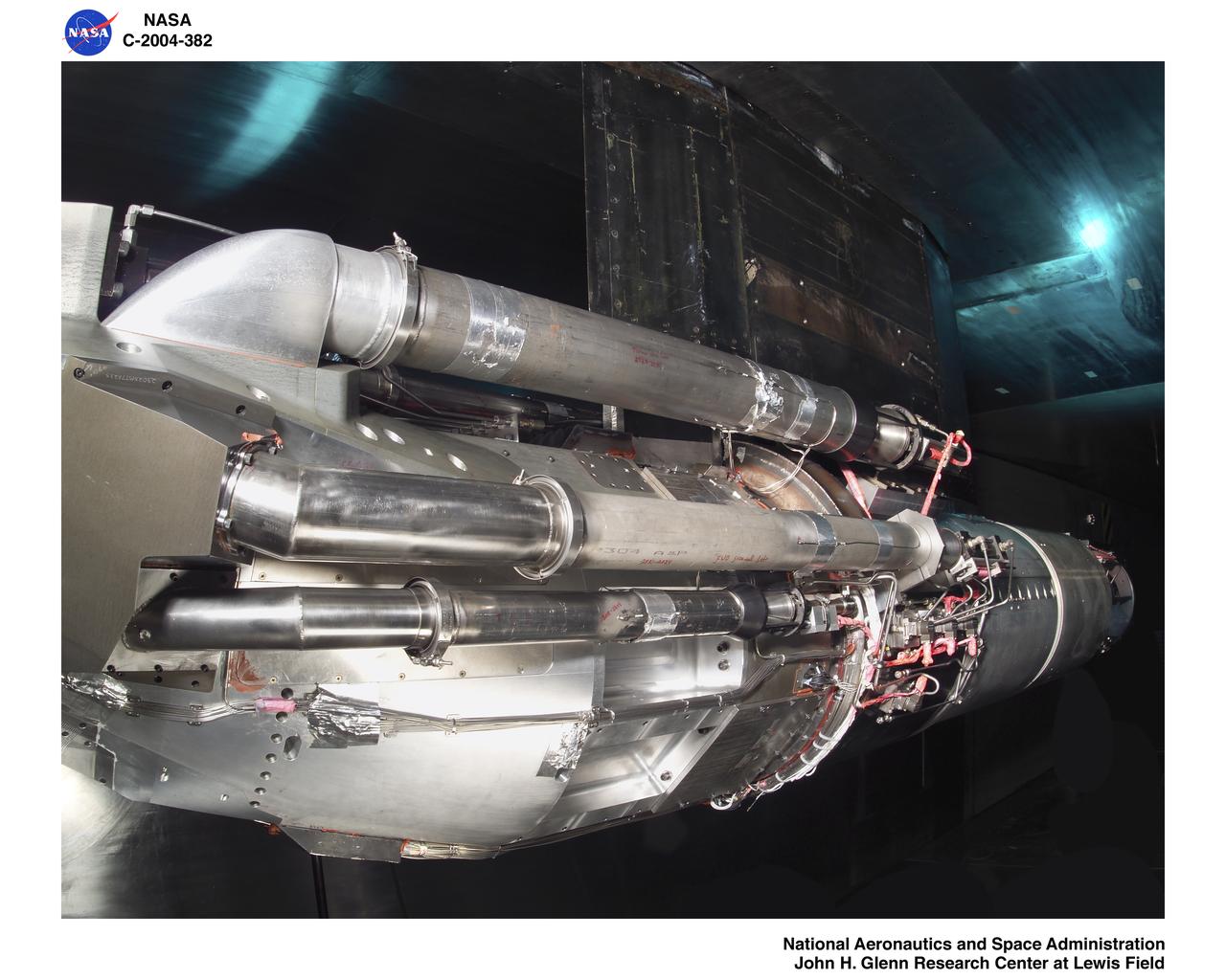
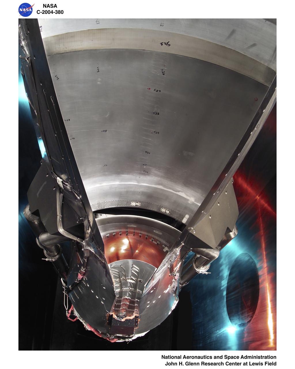
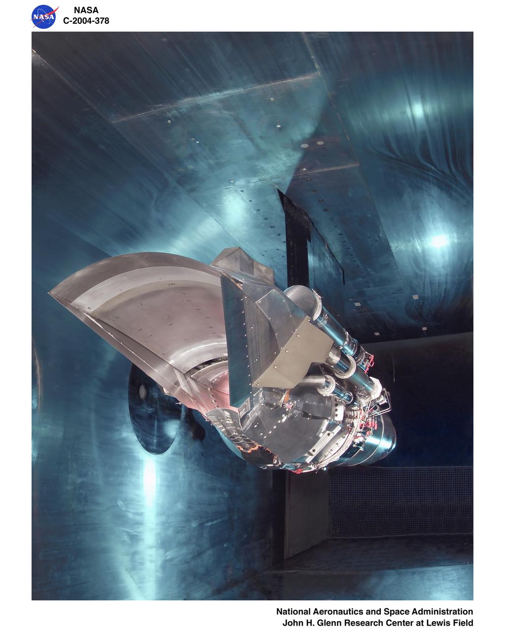
Brent Miller, of the V/STOL and Noise Division at the National Aeronautics and Space Administration (NASA) Lewis Research Center, poses with a sonic inlet for the NASA Quiet Engine Program. NASA Lewis had first investigated methods for reducing aircraft engine noise in the mid-1950s. Those efforts were resurrected and expanded in the late 1960s. The researchers found that the use of a sonic, or high-throat-Mach-number, inlet was effective at reducing the noise from the engine inlet. The device accelerated the inlet air to near-sonic speeds which kept the forward moving sound waves away from the inlet. The device also deflected the sound waves into the wall to further reduce the noise. NASA Lewis researchers tested models of the sonic inlet in their 9- by 15-Foot Low Speed Wind Tunnel. They found that the general level of aerodynamic performance was good. The tests during simulated takeoff and landing conditions demonstrated the sonic inlet’s ability to provide good aerodynamic and acoustic performance The researchers then successfully tested two full-scale sonic inlet designs, one from Pratt and Whitney and one from General Electric, with fans. A full-scale engine was installed on a thrust stand to determine the sonic inlet’s effect on the engine’s performance. The amount of noise reduction increased as the inlet flow velocity increased, but the full-scale tests did not produce as great a decrease in noise as the earlier small-scale tests.
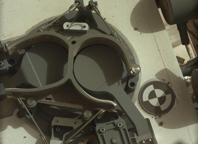
This subframe image from the left Mastcam on NASA Mars rover Curiosity shows the covers in place over two sample inlet funnels of the rover Sample Analysis at Mars SAM instrument suite.
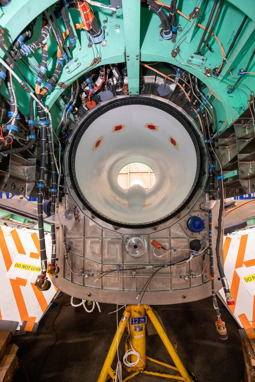
This image shows the X-59’s engine inlet from the aft view, which is the rear of the airplane, looking forward. Once the aircraft and ground testing are complete, the X-59 will undergo flight testing, which will demonstrate the plane’s ability to fly supersonic - faster than the speed of sound - while reducing the loud sonic boom. This could enable commercial supersonic air travel over land again.
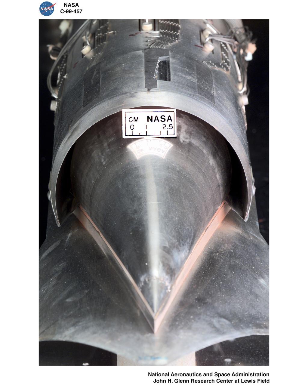
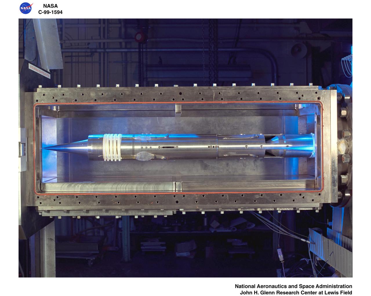
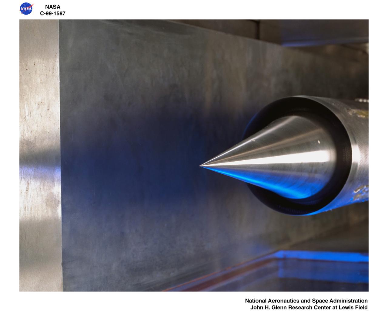
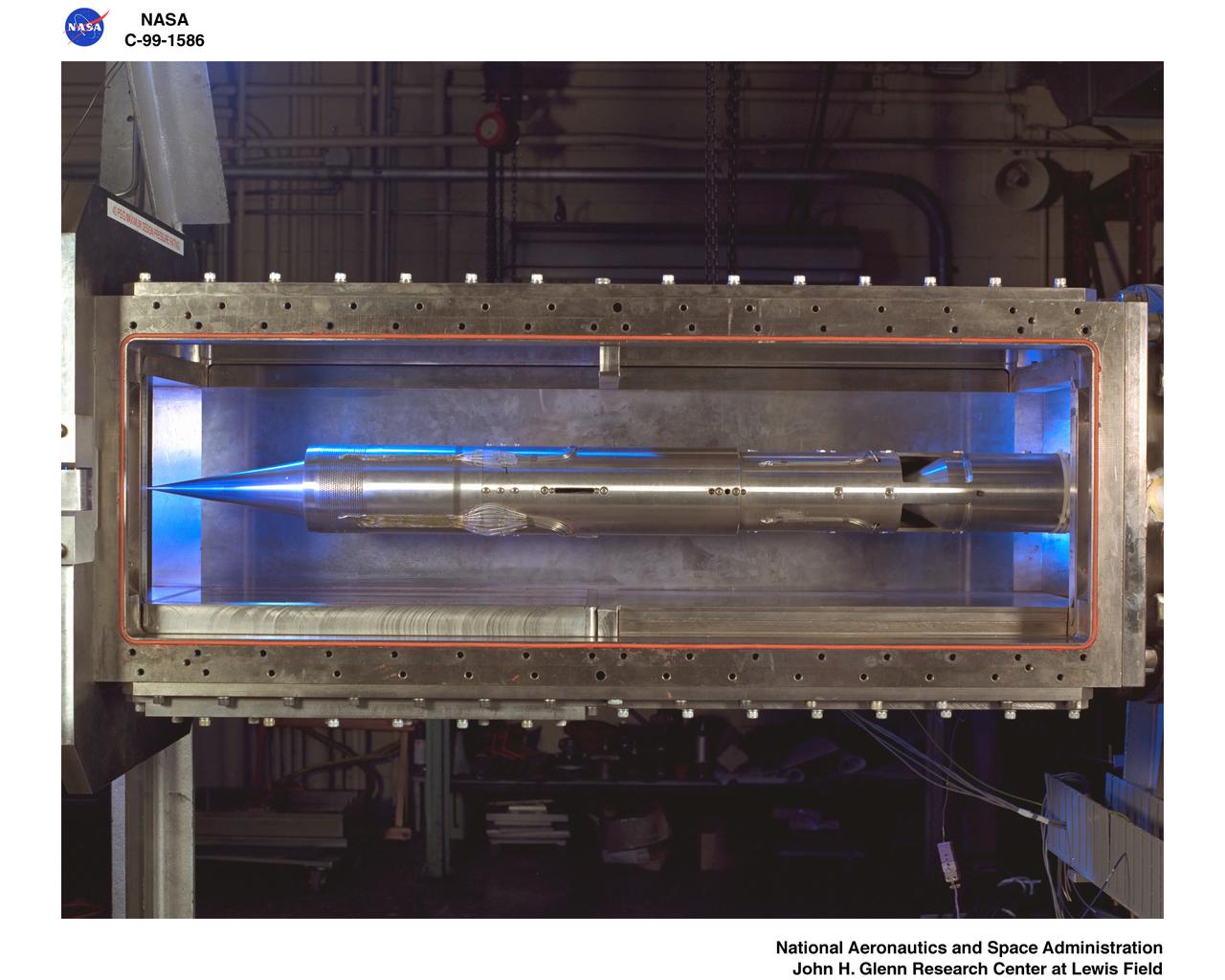
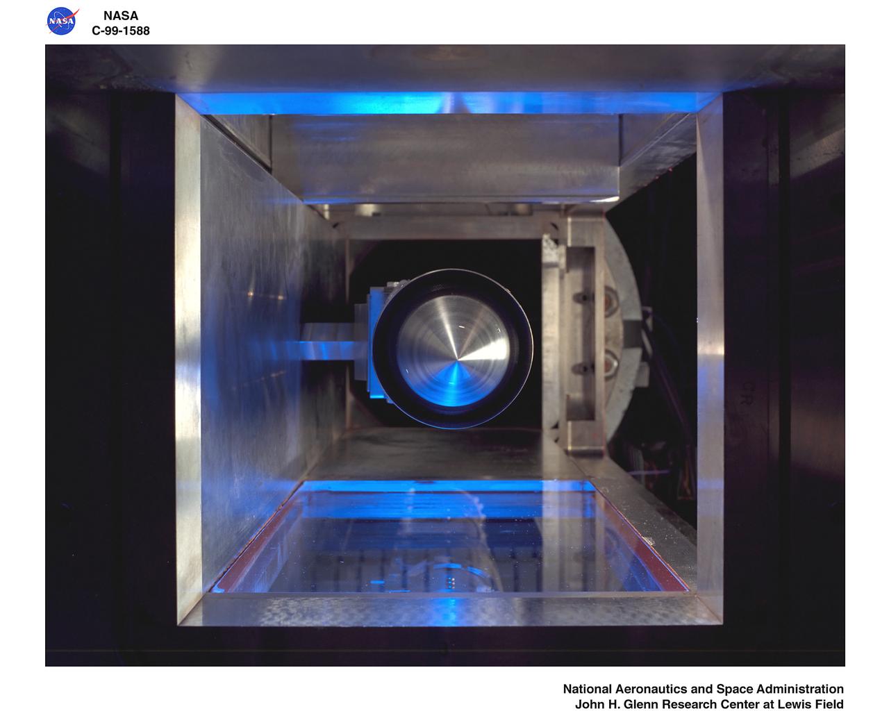
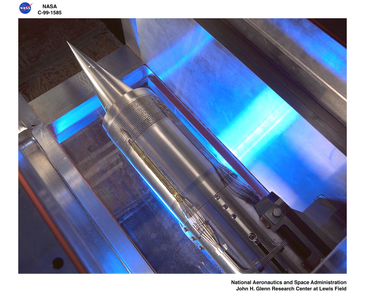
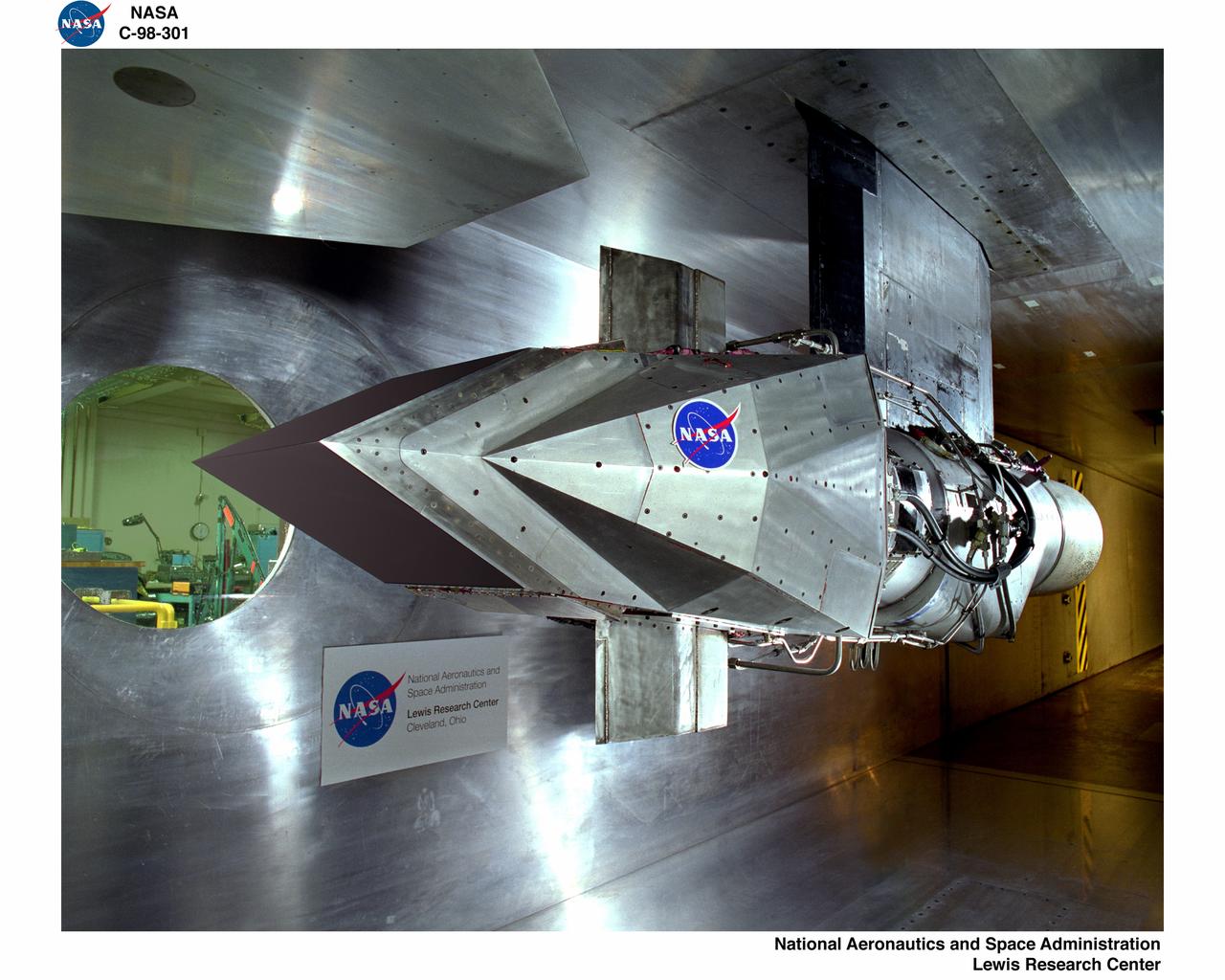
Mach number 6.9 Inlet. These negatives in jackets also: L-1958-2984.1 Figure 3b cone in NASA document L-1643 L-1958-2980.1 Figures 3a in document L-1643 declassified from Confidential
3/4 front view of Douglas F5D Skylancer modified to "ogee" platform inlet plug installed in Ames 40x80 foot wind tunnel.
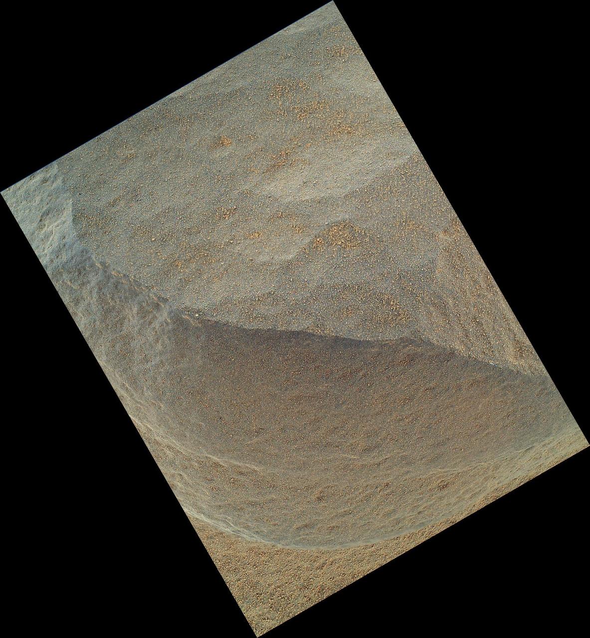
This is the highest-resolution view that the MAHLI camera on NASA Mars rover Curiosity acquired of the top of a rock called Bathurst Inlet; the rock is dark gray and is so fine-grained that MAHLI cannot resolve grains or crystals in it.

NASA Mars rover Curiosity held its MAHLI camera about 10.5 inches 27 centimeters away from the top of a rock called Bathurst Inlet for a set of eight images combined into this merged-focus view of the rock.
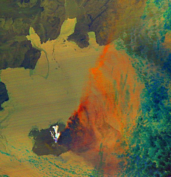
Since last spring, the U.S. Geological Survey Alaska Volcano Observatory AVO has detected increasing volcanic unrest at Augustine Volcano in Cook Inlet, Alaska near Anchorage. This image is from NASA Terra spacecraft.

Since last spring, the U.S. Geological Survey Alaska Volcano Observatory AVO has detected increasing volcanic unrest at Augustine Volcano in Cook Inlet, Alaska near Anchorage. This image is from NASA Terra spacecraft.
Parametric Inlet Model in 10x10 Wind Tunnel
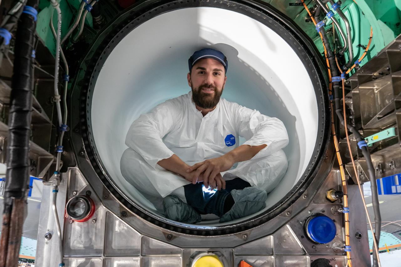
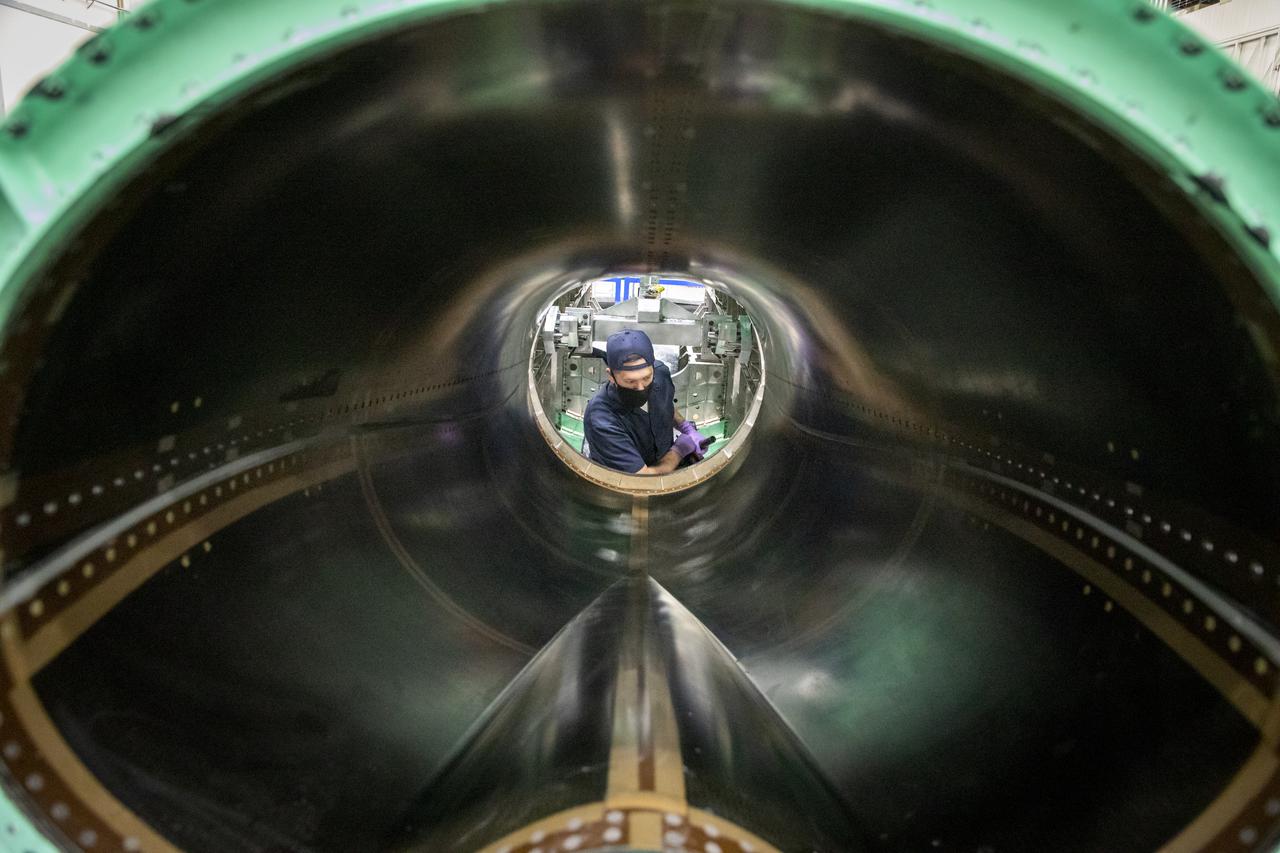
A Lockheed Martin Skunk Works technician takes a break for a photo. Note that the technician is wearing protective clean gear while sitting inside the X-59 engine inlet. Wearing this gear reduces the chance of any foreign objects from damaging the engine inlet.
Pictured here is a side view of the X-59 spine and engine inlet during assembly. Lockheed Martin Photography By Garry Tice 1011 Lockheed Way, Palmdale, Ca. 93599 Event: SEG 210 Forebody, SEG 430 Spine, SEG 500 Empennage Date: 6/08/2021
A Highly Maneuverable Aircraft Technology (HiMAT) inlet model installed in the test section of the 8- by 6-Foot Supersonic Wind Tunnel at the National Aeronautics and Space Administration (NASA) Lewis Research Center. Engineers at the Ames Research Center, Dryden Flight Research Center, and Rockwell International designed two pilotless subscale HiMAT vehicles in the mid-1970s to study new design concepts for fighter aircraft in the transonic realm without risking the lives of test pilots. The aircraft used sophisticated technologies such as advanced aerodynamics, composite materials, digital integrated propulsion control, and digital fly-by-wire control systems. In late 1977 NASA Lewis studied the HiMAT’s General Electric J85-21 jet engine in the Propulsion Systems Laboratory. The researchers charted the inlet quality with various combinations anti-distortion screens. HiMAT employed a relatively short and curved inlet compared to actual fighter jets. In the spring of 1979, Larry Smith led an in-depth analysis of the HiMAT inlet in the 8- by 6 tunnel. The researchers installed vortex generators to battle flow separation in the diffuser. The two HiMAT aircraft performed 11 hours of flying over the course of 26 missions from mid-1979 to January 1983 at Dryden and Ames. Although the HiMAT vehicles were considered to be overly complex and expensive, the program yielded a wealth of data that would validate computer-based design tools.
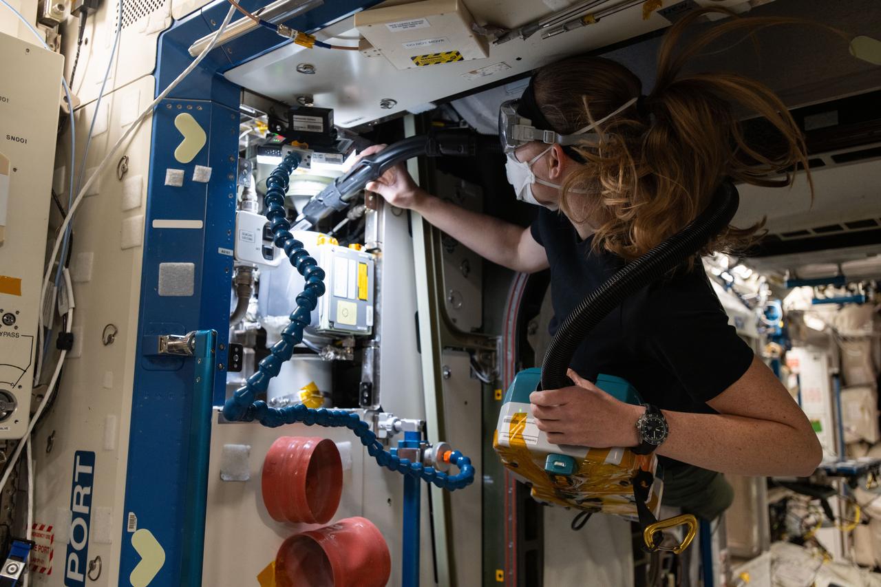
iss072e919611 (April 2, 2025) --- NASA astronaut and Expedition 72 Flight Engineer Nichole Ayers cleans ventilation system fans and inlets inside the International Space Station's Destiny labortory module.
A technician is working on the engine inlet of NASA’s X-59 Quiet Supersonic Technology (QueSST) aircraft at Lockheed Martin’s Skunk Works facility in Palmdale, California.
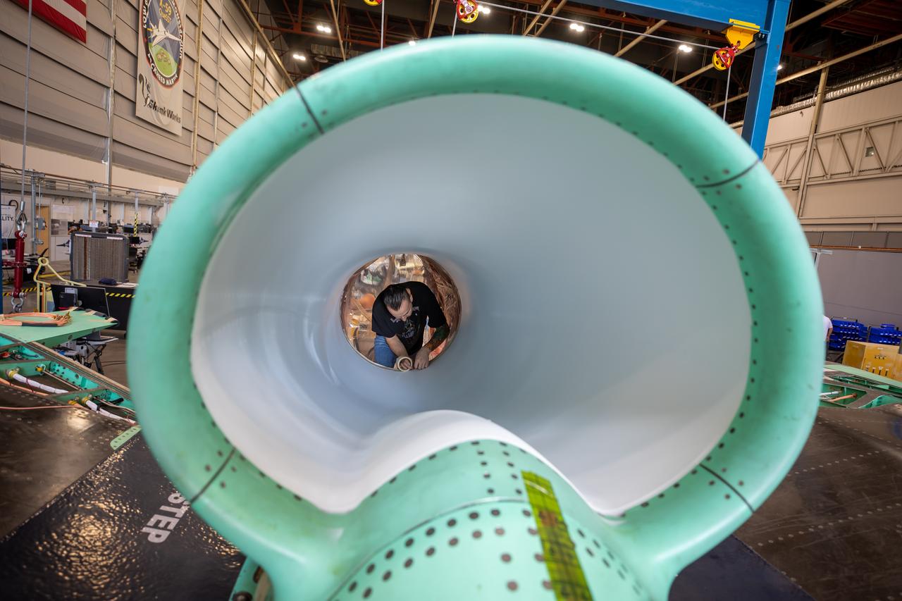
This is an up-close view of the X-59’s engine inlet – fresh after being painted. The 13-foot F414-GE-100 engine will be placed inside the inlet bringing the X-59 aircraft one step closer to completion. Once fully assembled, the X-59 aircraft will begin flight operations, working toward demonstration of the ability to fly supersonic while reducing the loud sonic boom to a quiet sonic thump, helping to enable commercial supersonic air travel over land.
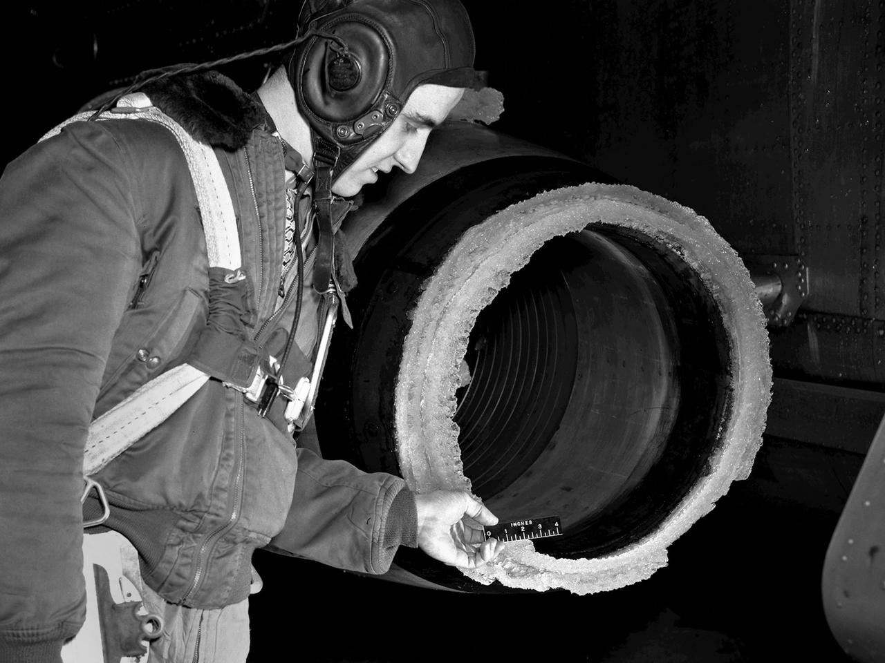
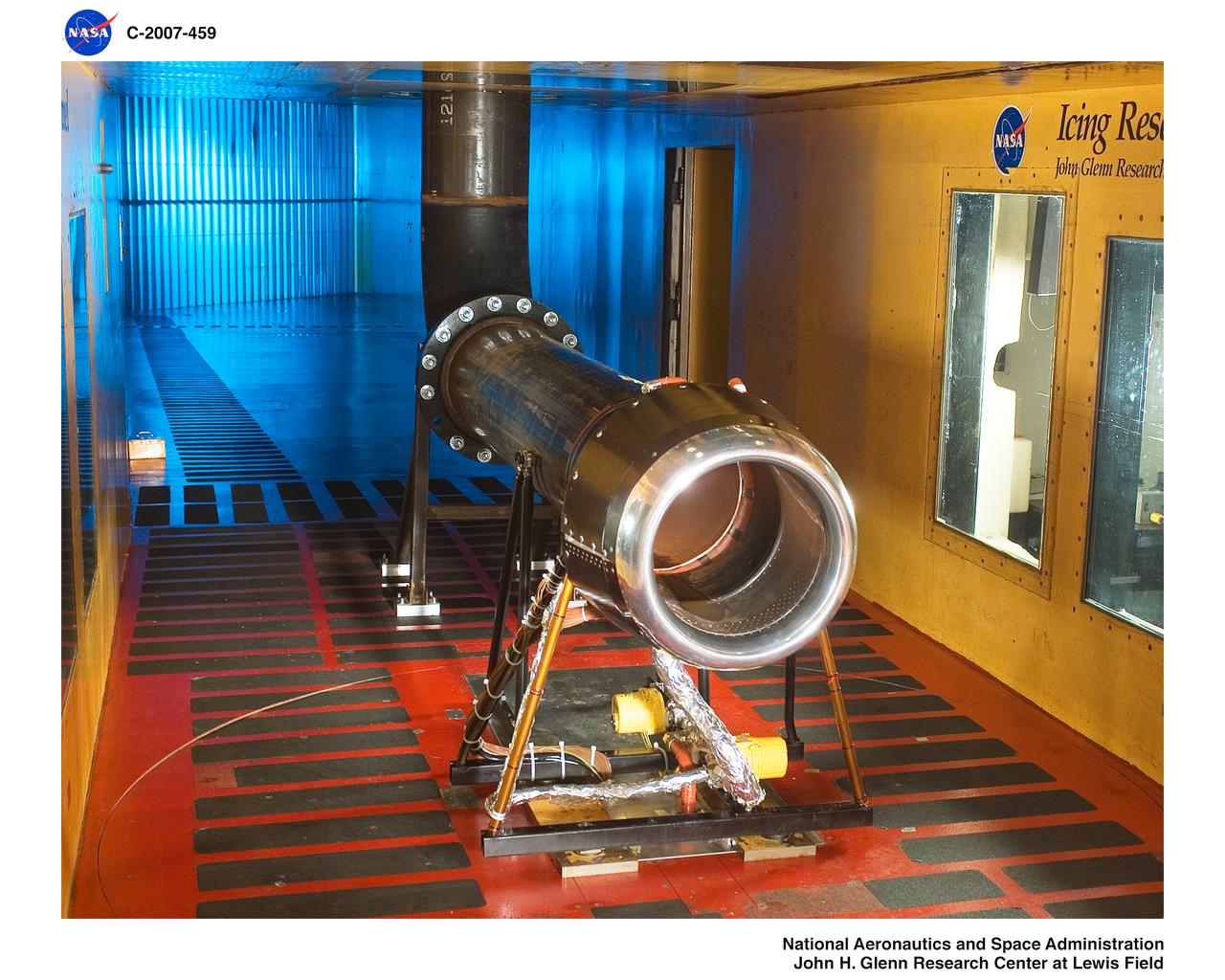
The National Advisory Committee for Aeronautics (NACA) Lewis Flight Propulsion Laboratory conducted an extensive icing research program in the late 1940s that included studies in the Icing Research Tunnel and using specially modified aircraft. One facet of this program was the investigation of the effects of icing on turbojets. Although jet engines allowed aircraft to pass through inclement weather at high rates of speed, ice accumulation was still a concern. The NACA’s B-24M Liberator was initially reconfigured with a General Electric I-16 engine installed in the aircraft’s waist compartment with an air scoop and spray nozzles to produce the artificial icing conditions. The centrifugal engine appeared nearly impervious to the effects of icing. Axial-flow jet engines, however, were much more susceptible to icing damage. The inlet guide vanes were particularly vulnerable, but the cowling’s leading edge, the main bearing supports, and accessory housing could also ice up. If pieces of ice reached the engine’s internal components, the compressor blades could be damaged. To study this phenomenon, a Westinghouse 24C turbojet, seen in this photograph, was installed under the B-24M’s right wing. In January 1948 flight tests of the 24C in icing conditions began. Despite ice buildup into the second stage of the compressor, the engine was able to operate at takeoff speeds. Researchers found the ice on the inlet vanes resulted in half of the engine’s decreased performance.
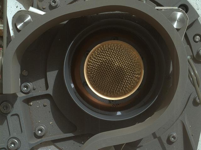
This image from NASA Curiosity rover shows the open inlet where powdered rock and soil samples will be funneled down for analysis.
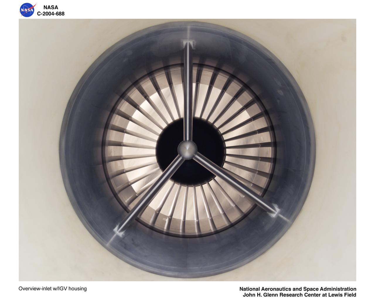
Overview-inlet with Inlet Guide Vane housing
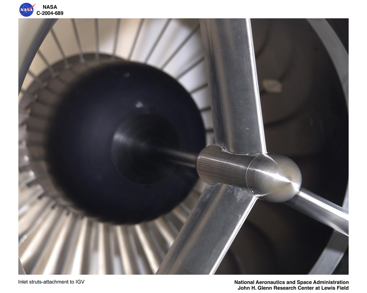
Inlet struts-attachment to Inlet Guide Vane
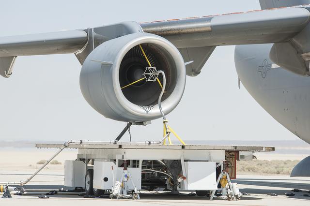
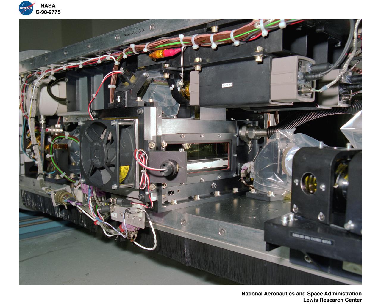
The volcanic ash distribution spider, shown here in the inlet of the engine while running, was used to send the ultra-fine particles of ash through the engine.
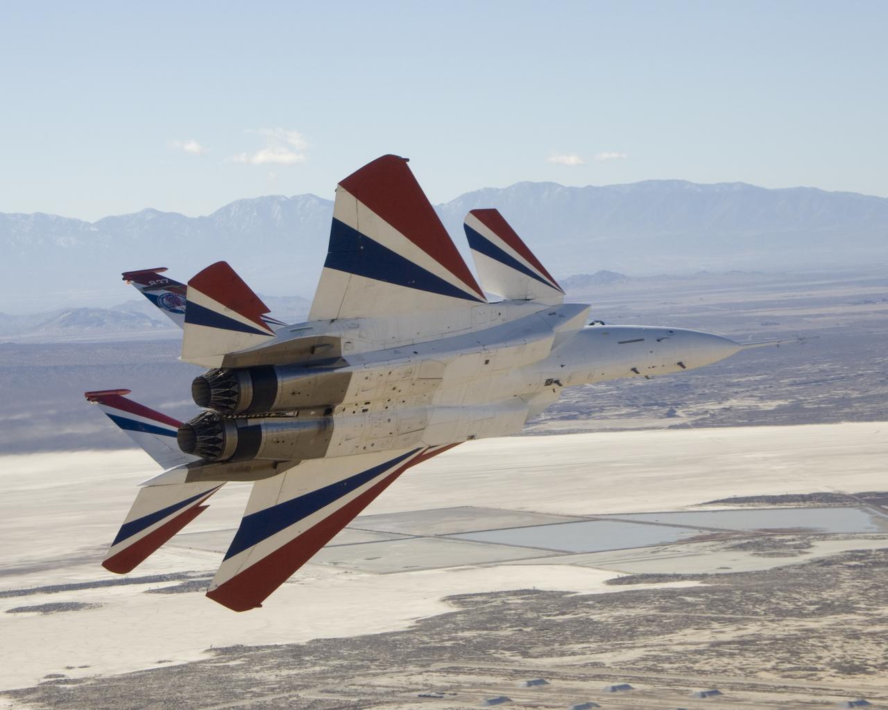
Two small Range Safety System antennas are located just behind the engine inlets of NASA's NF-15B research aircraft as it banks away from the chase plane.
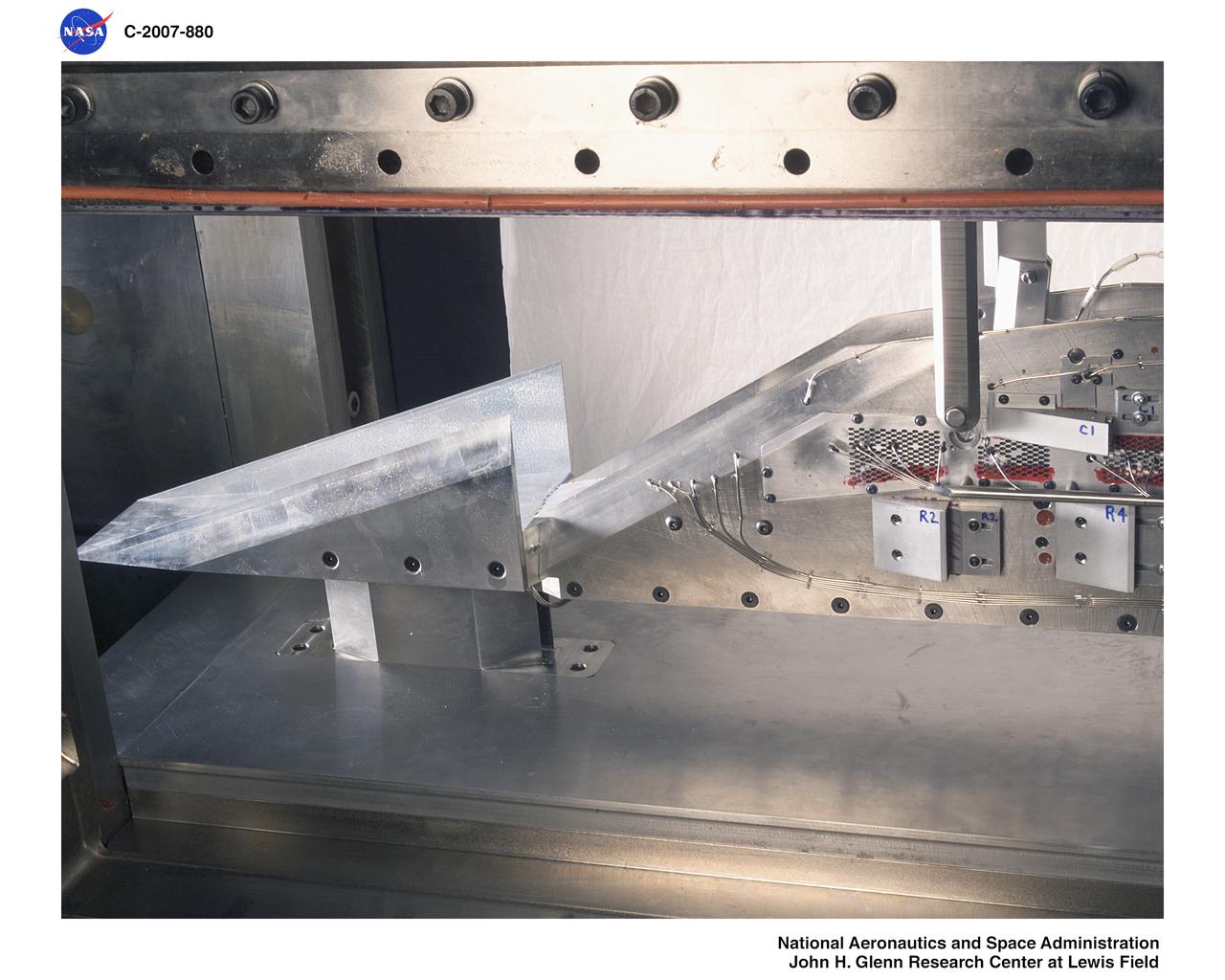
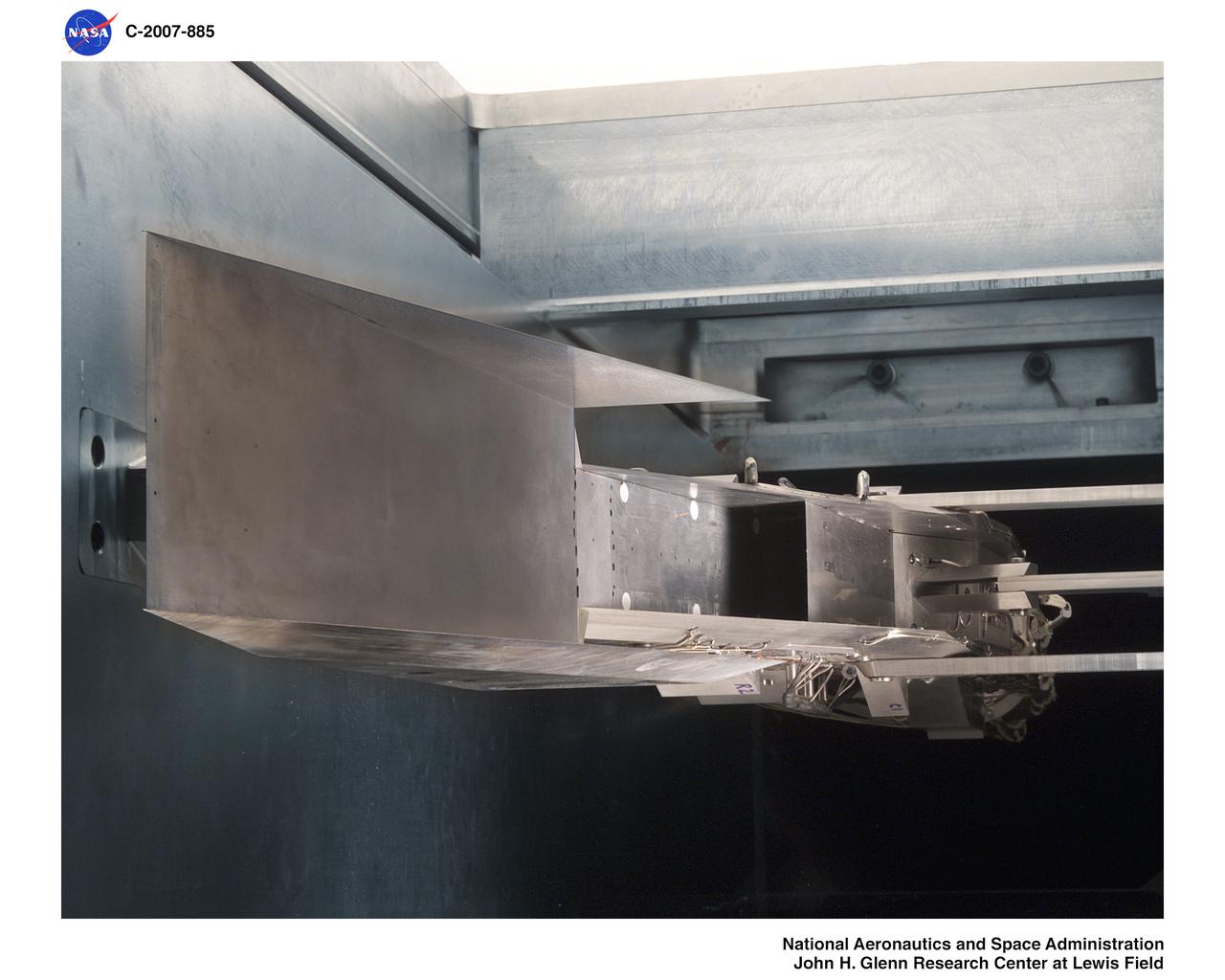
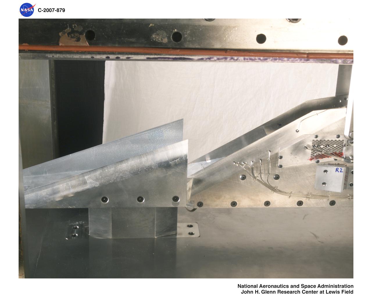
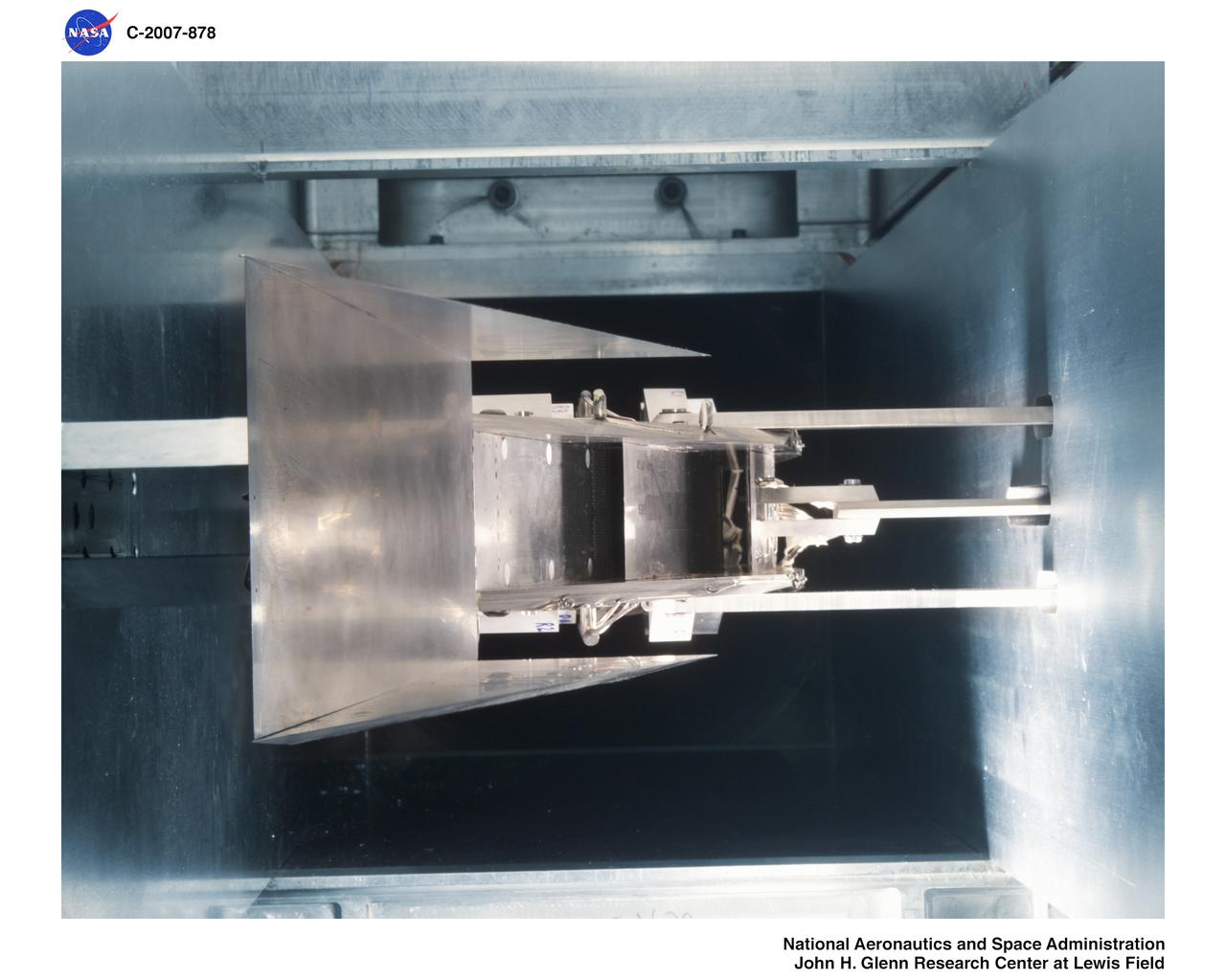
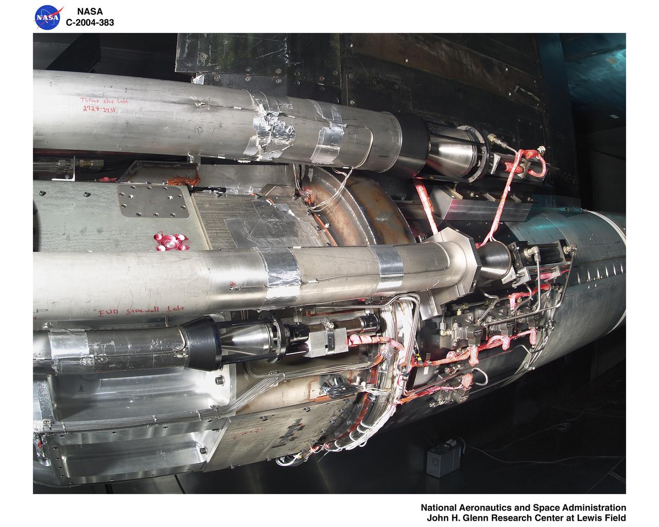
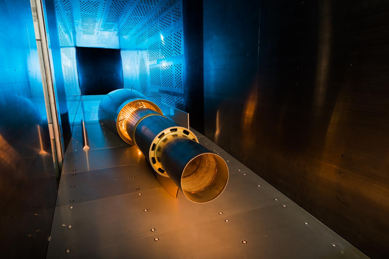
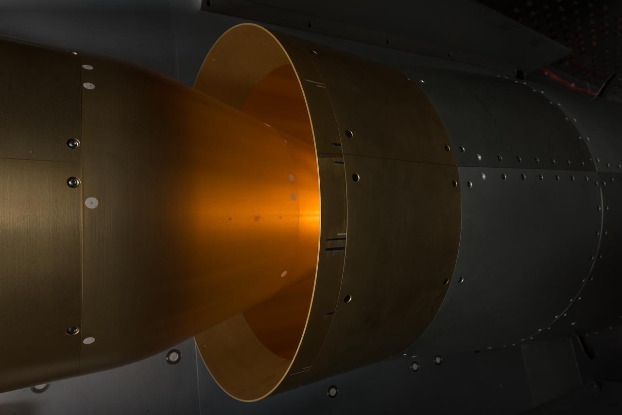
Large-Scale Low-Boom Inlet Test, Dual Stream Inlet in 8x6 Supersonic Wind Tunnel
IMX (Inlet Mode Transistion) Mach 4 Inlet Model in the 1x1 Wind Tunnel
Large-Scale Low-Boom Inlet Test Single Stream Inlet in 8x6 foot Supersonic Wind Tunnel
IMX (Inlet Mode Transistion) Mach 4 Inlet Model in the 1x1 Wind Tunnel
Large-Scale Low-Boom Inlet Test Single Stream Inlet in 8x6 foot Supersonic Wind Tunnel
IMX (Inlet Mode Transistion) Mach 4 Inlet Model in the 1x1 Wind Tunnel
IMX (Inlet Mode Transistion) Mach 4 Inlet Model in the 1x1 Wind Tunnel
This image shows the extensive ventilation system that has been placed adjacent to the X-59 during the recent painting of the aircraft’s engine inlet. Once the aircraft build and ground testing are complete, the X-59 airplane will begin flight testing, working towards demonstrating the ability to fly supersonic while reducing the loud sonic boom to a quiet sonic thump and help enable commercial supersonic air travel over land.

Flight evaluation and comparison of a NACA submerged inlet and a scoop inlet on the North American YF-93A (AF48-317 NACA-139). The YF-93A's were the first aircraft to use flush NACA engine inlets. aircraft to use flush NACA engine inlets. Note: Used in publication in Flight Research at Ames; 57 Years of Development and Validation of Aeronautical Technology NASA SP-1998-3300 and Memoirs of a Flight Test Engineer NASA SP-2001-4525
NORDAM INLET NACELLE
TRAILBLAZER INLET MODEL
NORDAM INLET NACELLE

TRAILBLAZER INLET TEST IN 1X1
TRAILBLAZER INLET TEST IN 1X1
NORDAM INLET NACELLE
TRAILBLAZER INLET 1X1
TRAILBLAZER INLET 1X1
TRAILBLAZER INLET TEST IN 1X1
This image from NASA Curiosity rover shows the cover on an inlet that will receive powdered rock and soil samples for analysis. The image also shows sand and angular and rounded pebbles that were deposited on the rover deck when it landed.

Nuuk or Gadthab is the capital and largest city of Greenland. It is located at the mouth of the Nuup Kangerlua inlet on the west coast of Greenland. This image was acquired August 2, 2004 by NASA Terra spacecraft.
This image from NASA Curiosity rover shows the inlet covers for the Sample Analysis at Mars instrument as the rover continues to check out its instruments in the first phase after landing.
Parametric Inlet Model in 10x10 Wind Tunnel
Parametric Inlet Model in 10x10 Wind Tunnel
Parametric Inlet Model in 10x10 Wind Tunnel
BELL 609 SPINNER INLET ICING MODEL
BELL 609 SPINNER INLET ICING MODEL
Kelly Aerospace 727 inlet anti-icing model
ATREX INLET MODEL IN 1X1 FOOT WIND TUNNEL
ATREX INLET MODEL IN 1X1 FOOT WIND TUNNEL
ATREX INLET MODEL IN 1X1 FOOT WIND TUNNEL
BELL 609 SPINNER INLET ICING MODEL
ATREX INLET MODEL IN 1X1 FOOT WIND TUNNEL
ATREX INLET MODEL IN 1X1 FOOT WIND TUNNEL
BELL 609 SPINNER INLET ICING MODEL

BELL 609 SPINNER INLET ICING MODEL
Parametric Inlet Model in 10x10 Wind Tunnel
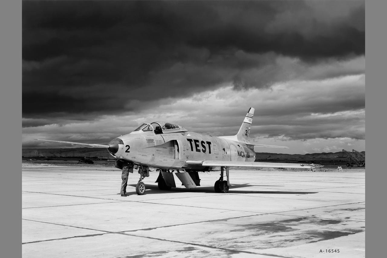
YF-93A (AF48-318 NACA-151) Flight evaluation and comparison of a NACA submerged inlet and a scoop inlet. The YF-93A's were the first aircraft to use flush NACA engine inlets. Note: Used in Flight Research at Ames; 57 Years of Development and Validation of Aeronautical Technology NASA SP-1998-3300 Fig.25
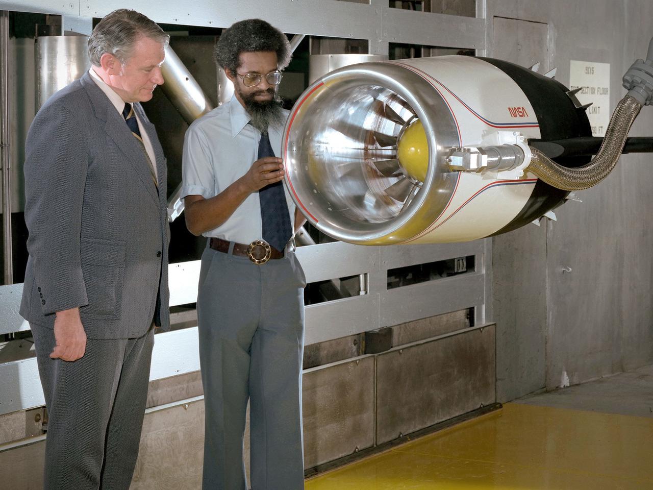
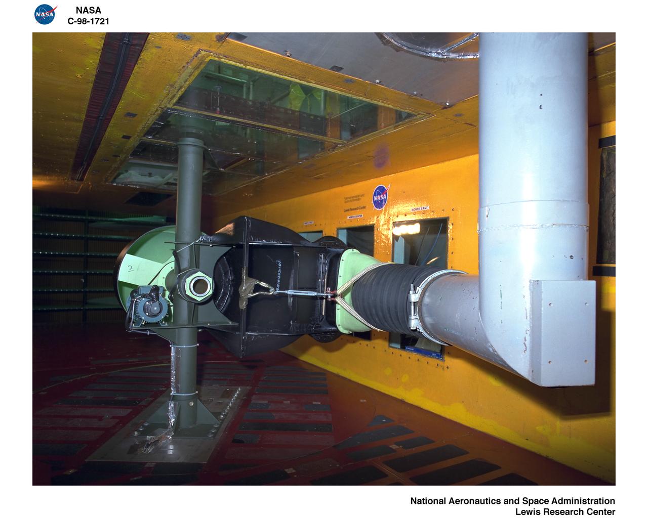
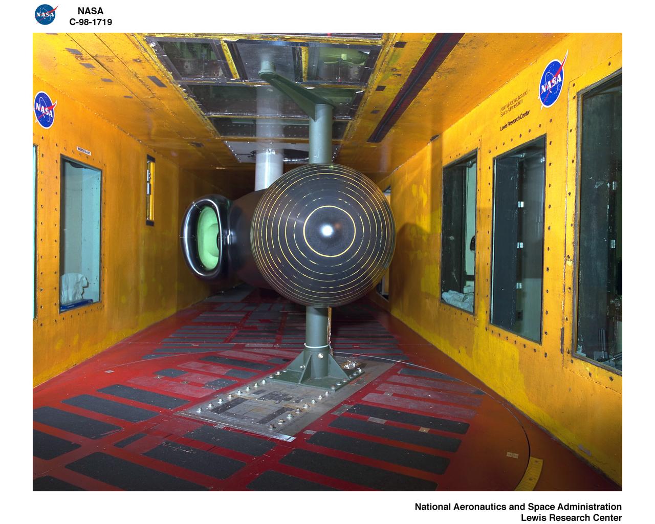
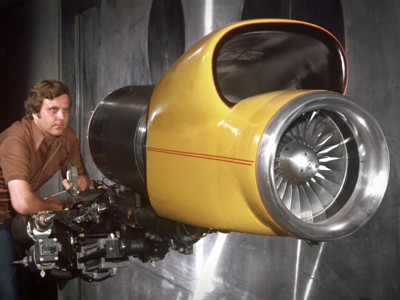
Center Director John McCarthy, left, and researcher Al Johns pose with a one-third scale model of a Grumman Aerospace tilt engine nacelle for Vertical and Short Takeoff and Landing (V/STOL) in the 9- by 15-Foot Low Speed Wind Tunnel at the National Aeronautics and Space Administration (NASA) Lewis Research Center. Lewis researchers had been studying tilt nacelle and inlet issues for several years. One area of concern was the inlet flow separation during the transition from horizontal to vertical flight. The separation of air flow from the inlet’s internal components could significantly stress the fan blades or cause a loss of thrust. In 1978 NASA researchers Robert Williams and Al Johns teamed with Grumman’s H.C. Potonides to develop a series of tests in the Lewis 9- by 15-foot tunnel to study a device designed to delay the flow separation by blowing additional air into the inlet. A jet of air, supplied through the hose on the right, was blown over the inlet surfaces. The researchers verified that the air jet slowed the flow separation. They found that the blowing on boundary layer control resulted in a doubling of the angle-of-attack and decreases in compressor blade stresses and fan distortion. The tests were the first time the concept of blowing air for boundary layer control was demonstrated. Boundary layer control devices like this could result in smaller and lighter V/STOL inlets.

An inlet duct lowered into the 20-foot diameter test section of the Altitude Wind Tunnel at the National Advisory Committee for Aeronautics (NACA) Lewis Flight Propulsion Laboratory. Engines and hardware were prepared in the facility’s shop area. The test articles were lifted by a two-rail Shaw box crane through the high-bay and the second-story test chamber before being lowered into the test section. Technicians then spent days or weeks hooking up the supply lines and data recording telemetry. The engines were mounted on wingspans that stretched across the test section. The wingtips attached to the balance frame’s trunnions, which could adjust the angle of attack. The balance frame included six devices that recorded data and controlled the engine. The measurements were visible in banks of manometer boards next to the control room. Photographs recorded the pressure levels in the manometer tubes, and the computing staff manually converted the data into useful measurements. A mechanical pulley system was used to raise and lower the tunnel’s large clamshell lid into place. The lid was sealed into place using hand-turned locks accessible from the viewing platform. The lid had viewing windows above and below the test article, which permitted the filming and visual inspection of the tests.

The NASA Dryden 747 Shuttle Carrier Aircraft crew poses in an engine inlet; Standing L to R - aircraft mechanic John Goleno and SCA Team Leader Pete Seidl; Kneeling L to R - aircraft mechanics Todd Weston and Arvid Knutson, and avionics technician Jim Bedard NASA uses two modified Boeing 747 jetliners, originally manufactured for commercial use, as Space Shuttle Carrier Aircraft (SCA). One is a 747-100 model, while the other is designated a 747-100SR (short range). The two aircraft are identical in appearance and in their performance as Shuttle Carrier Aircraft. The 747 series of aircraft are four-engine intercontinental-range swept-wing "jumbo jets" that entered commercial service in 1969. The SCAs are used to ferry space shuttle orbiters from landing sites back to the launch complex at the Kennedy Space Center, and also to and from other locations too distant for the orbiters to be delivered by ground transportation. The orbiters are placed atop the SCAs by Mate-Demate Devices, large gantry-like structures which hoist the orbiters off the ground for post-flight servicing, and then mate them with the SCAs for ferry flights.
General Atomics - Predator B Inlet Model in the Icing Research Tunnel
General Atomics - Predator B Inlet Model in the Icing Research Tunnel
10X10 FOOT WIND TUNNEL 2D INLET J85 ENGINE MODEL
SPREAD ACROSS LIQUIDS SAL 5 TRAY INLET / OUTLET SURFACES
10X10 FOOT WIND TUNNEL 2D INLET J85 ENGINE MODEL
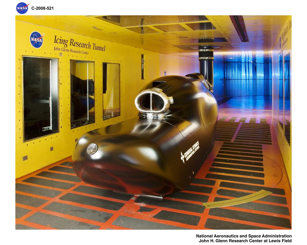
General Atomics - Predator B Inlet Model in the Icing Research Tunnel

F/A-18 (F-18) outside the 80x120ft w.t. inlet (it will be loaded in the tunnel for testing)
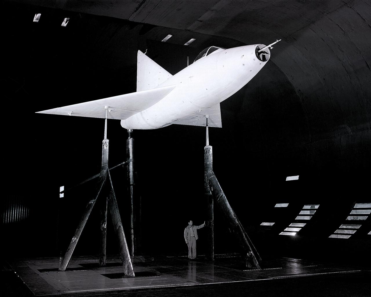
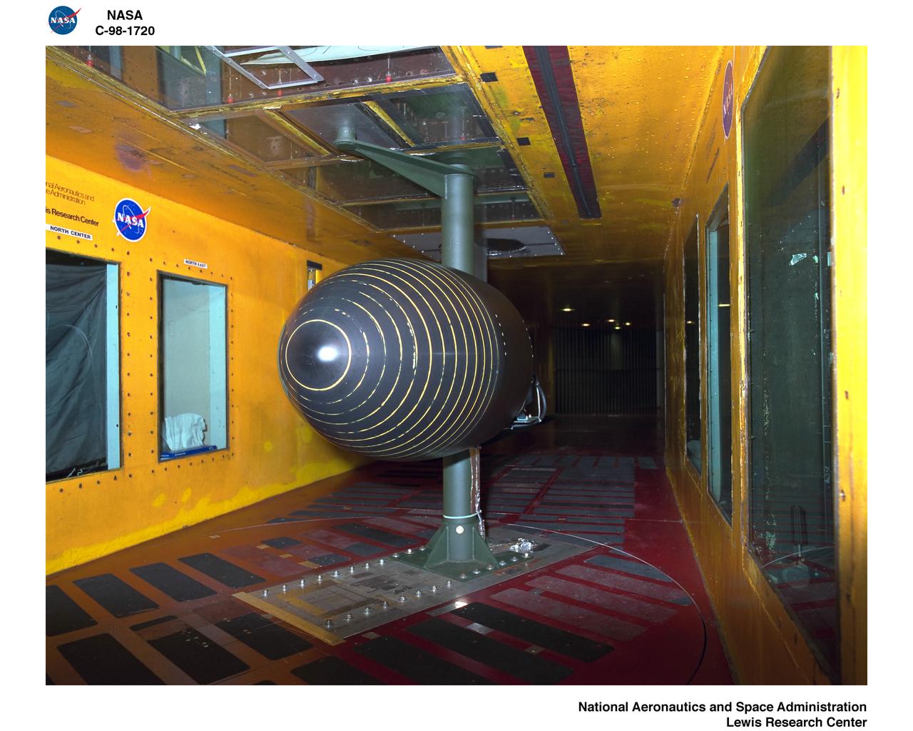
3/4 front view from below of Delta wing Model with Nose Inlet in Ames 40x80 foot wind tunnel.
YF-12 inlet airframe interaction test in Ames 8X7ft supersonic wind tunnel
ACOUSTIC NOISE CONTROL FAN RIG INLET CONTROL DEVICE BOEING ICED TEAM
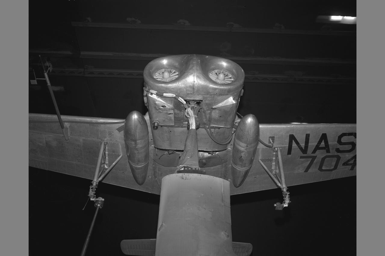
X-14 NASA 704 Full Scale Airplane tests in 40x80ft. Wind Tunnel (NORMAL MOUNTING) jet inlets
The Blue Angels crew tour the inlet of the NFAC’s 80-by-120-foot wind tunnel test section in building N221.
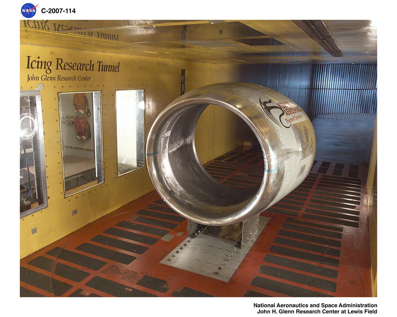
The FJ33 Engine Inlet from Williams International being tested in the Icing Research Tunnel

Date: Dec 6, 1951 NACA Photographer North American YF-93 with submerged divergent-wall engine-air inlet. Maximum high-speed capability of Mach 1.03 was obtained with afterbrner on. Tests were conducted to compare high-speed performance of the YF-93 NACA-139 airplane with different inlet configurations. (Mar 1953)
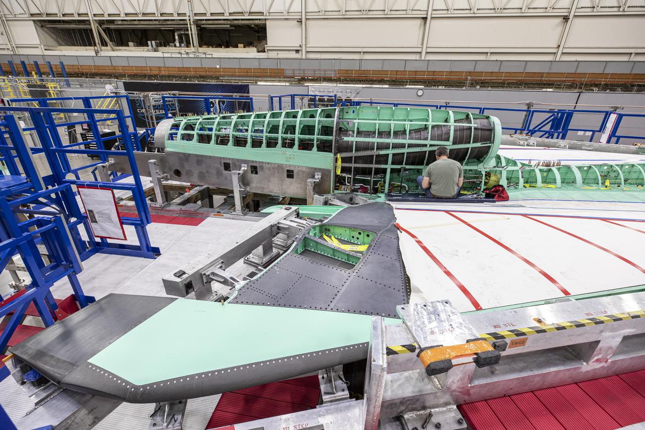
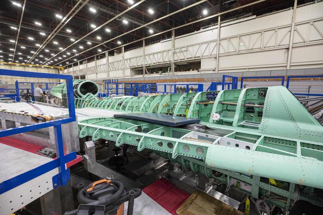
Here is a wide shot of the wing, engine and engine inlet area of NASA’s X-59 Quiet SuperSonic Technology or QueSST aircraft. The aircraft, under construction at Lockheed Martin Skunk Works in Palmdale, California, will fly to demonstrate the ability to fly supersonic while reducing the loud sonic boom to a quiet sonic thump. Lockheed Martin Photography By Garry Tice 1011 Lockheed Way, Palmdale, Ca. 93599 Event: SEG 400 Main Wing Assembly, SEG 430 Spine, SEG 500 Empennage Date: 4/28/2021
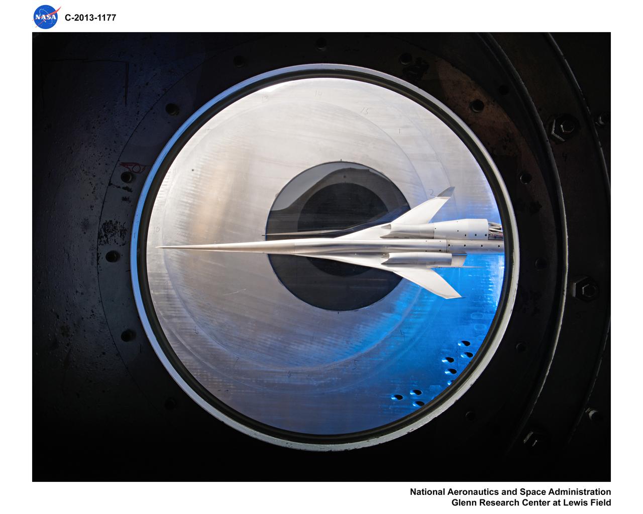
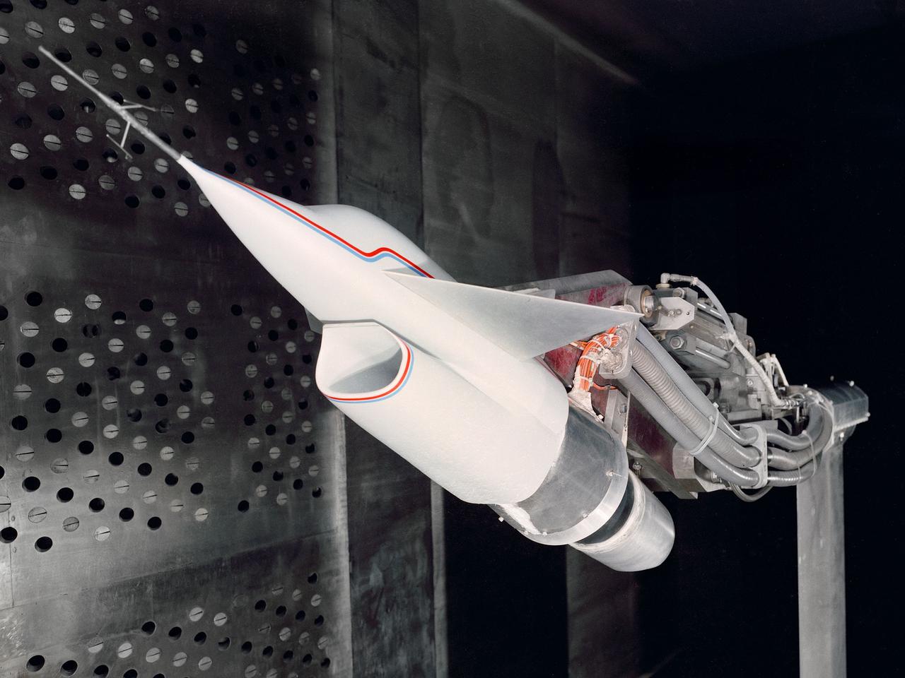
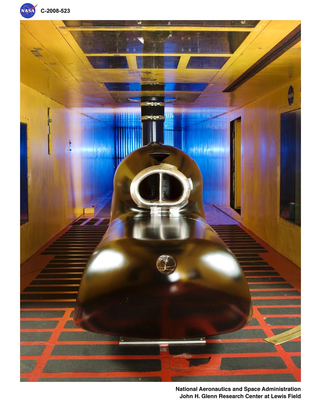
Supersonic Aircraft Model The window in the sidewall of the 8- by 6-foot supersonic wind tunnel at NASA's Glenn Research Center shows a 1.79 percent scale model of a future concept supersonic aircraft built by The Boeing Company. In recent tests, researchers evaluated the performance of air inlets mounted on top of the model to see how changing the amount of airflow at supersonic speeds through the inlet affected performance. The inlet on the pilot's right side (top inlet in this side view) is larger because it contains a remote-controlled device through which the flow of air could be changed. The work is part of ongoing research in NASA's Aeronautics Research Mission Directorate to address the challenges of making future supersonic flight over land possible. Researchers are testing overall vehicle design and performance options to reduce emissions and noise, and identifying whether the volume of sonic booms can be reduced to a level that leads to a reversal of the current ruling that prohibits commercial supersonic flight over land. Image Credit: NASA/Quentin Schwinn
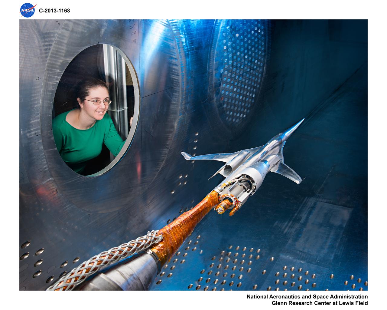
Supersonic Aircraft Model The window in the sidewall of the 8- by 6-foot supersonic wind tunnel at NASA's Glenn Research Center shows a 1.79 percent scale model of a future concept supersonic aircraft built by The Boeing Company. In recent tests, researchers evaluated the performance of air inlets mounted on top of the model to see how changing the amount of airflow at supersonic speeds through the inlet affected performance. The inlet on the pilot's right side (top inlet in this side view) is larger because it contains a remote-controlled device through which the flow of air could be changed. The work is part of ongoing research in NASA's Aeronautics Research Mission Directorate to address the challenges of making future supersonic flight over land possible. Researchers are testing overall vehicle design and performance options to reduce emissions and noise, and identifying whether the volume of sonic booms can be reduced to a level that leads to a reversal of the current ruling that prohibits commercial supersonic flight over land. Image Credit: NASA/Quentin Schwinn

Raised Floor Calibration Hardware for the Boundary Layer Ingesting Inlet Distortion Tolerant Fan tests to be performed in the 8' x 6' Supersonic Wind Tunnel at NASA Glenn Research Center.
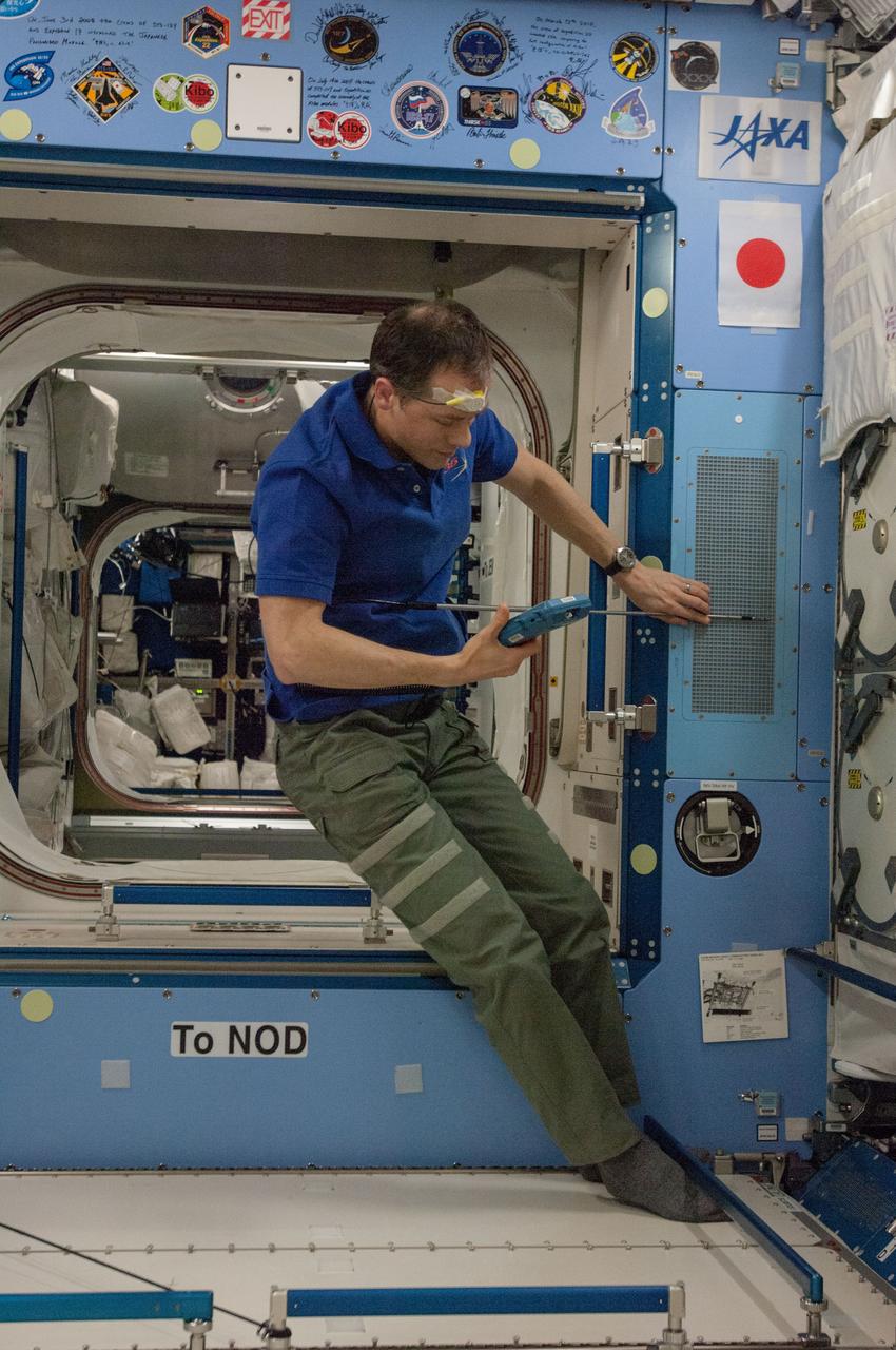
ISS035-E-020060 (15 April 2013) --- NASA astronaut Tom Marshburn works on the Inter Module Ventilation (IMV) Flow Measurement in Kibo Japanese Experiment Module (JEM)aboard the Earth-orbiting International Space Station. Expedition 35 Commander Chris Hadfield, an astronaut with the Canadian Space Agency, and Marshburn set up the velocicalc hardware and measured the IMV flow coming from the JEM Pressurized Module (JPM) IMV overhead aft inlet, starboard aft inlet, and starboard forward outlet. The measurements are part of routine preventative maintenance to ensure quality airflow in the modules.
A technician checks a 0.25-scale engine model of a Vought Corporation V-530 engine in the test section of the 10- by 10-Foot Supersonic Wind Tunnel at the National Aeronautics and Space Administration (NASA) Lewis Research Center. Vought created a low-drag tandem-fan Vertical/Short and Takeoff and Landing (V/STOL) engine in the mid-1970s, designated as the V-530. The first fan on the tandem-fan engine was supplied with air through a traditional subsonic inlet, seen on the lower front of the engine. The air was exhausted through the nacelle during normal flight and directed down during takeoffs. The rear fan was supplied by the oval-shaped top inlet during all phases of the flight. The second fan exhausted its air through a rear vectorable nozzle. NASA Lewis and Vought partnered in the late 1970s to collect an array of inlet and nozzle design information on the tandem fan engines for the Navy. Vought created this .25-scale model of the V-530 for extensive testing in Lewis' 10- by 10-foot tunnel. During an early series of tests, the front fan was covered, and a turbofan simulator was used to supply air to the rear fan. The researchers then analyzed the performance of only the front fan inlet. During the final series of tests, the flow from the front fan was used to supply airflow to the rear fan. The researchers studied the inlet's recovery, distortion, and angle-of-attack limits over various flight conditions.
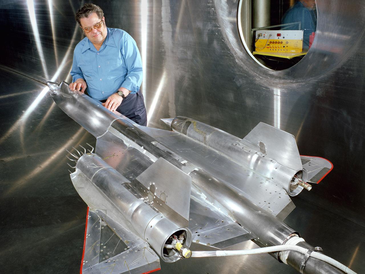
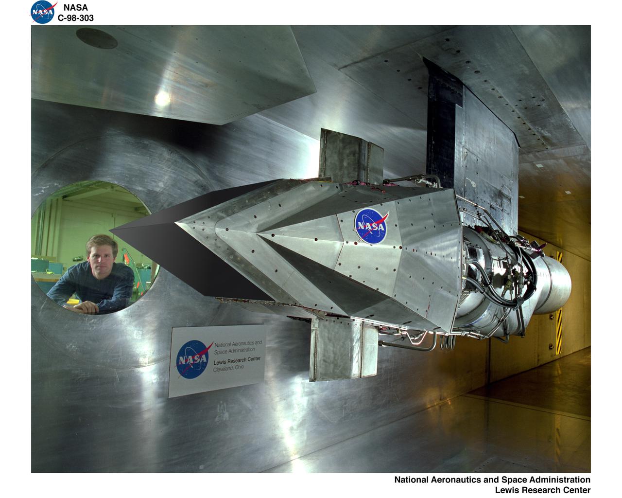
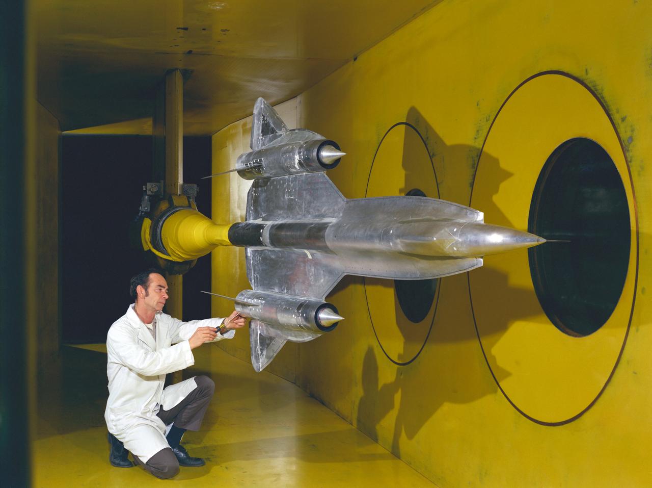
Robert Cubbison examines a model of the Lockheed YF-12 Blackbird in the test section of the 10- by 10-Foot Supersonic Wind Tunnel at the National Aeronautics and Space Administration (NASA) Lewis Research Center. The YF-12 was an experimental fighter version of Lockheed’s A-12 reconnaissance aircraft which had been developed into the renowned SR-71 Blackbird. NASA possessed two YF-12s at its Dryden Flight Research Center which could be used by researchers at all the NASA centers. During its nine-year life, the Dryden’s YF-12 research program logged 297 flights with approximately 450 flight hours. Lewis researchers were studying the YF-12’s inlet airflow in the 10- by 10-foot wind tunnel in late 1977. The advanced supersonic cruise aircraft of the time used mixed-compression inlets. These types of inlets were prone to flameout during atmospheric disturbances. Researchers at Lewis and Dryden developed a program to study these flameouts by artificially introducing flow disturbances. Testing at Dryden with a specially-equipped YF-12 aircraft yielded limited results. Lewis’ tests in the 10- by 10 were unsuccessful at inducing upstream disturbances. The researchers used two methods—a falling plate and a servo-driven wing.
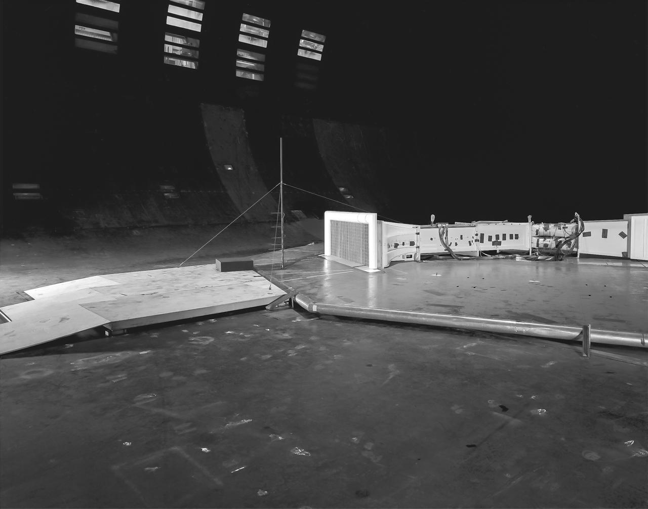
(03/12/1976) 1/50 scale model of the 80x120 foot wind tunnel model (NFAC) in the test section of the 40x80 wind tunnel. Model viewed from the west, mounted on a rotating ground board designed for this test. Ramp leading to ground board includes a generic building placed in front of the 80x120 inlet.
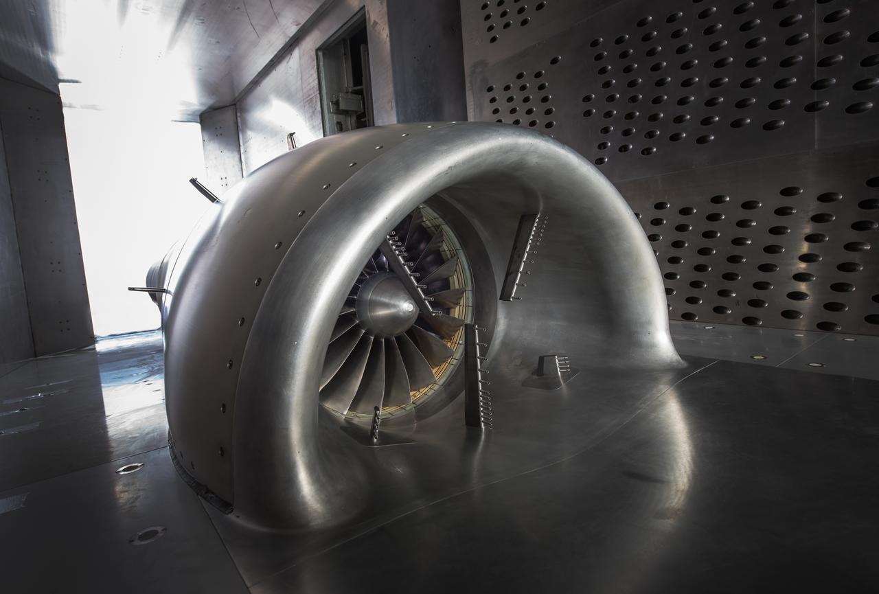
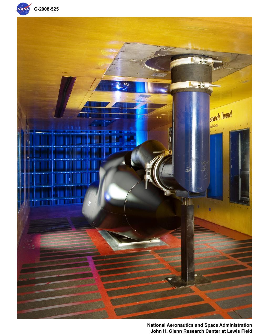
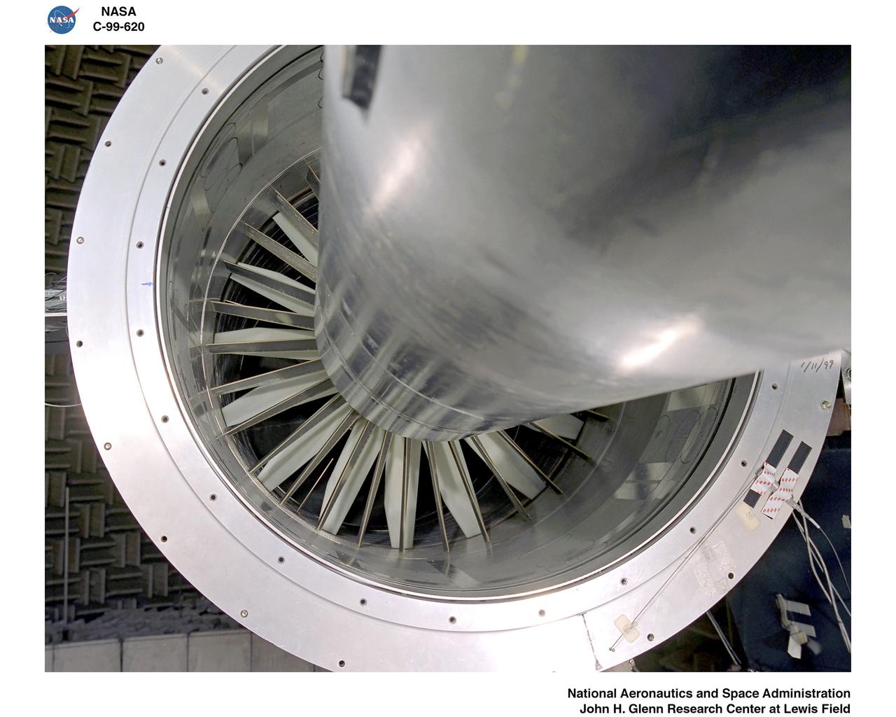
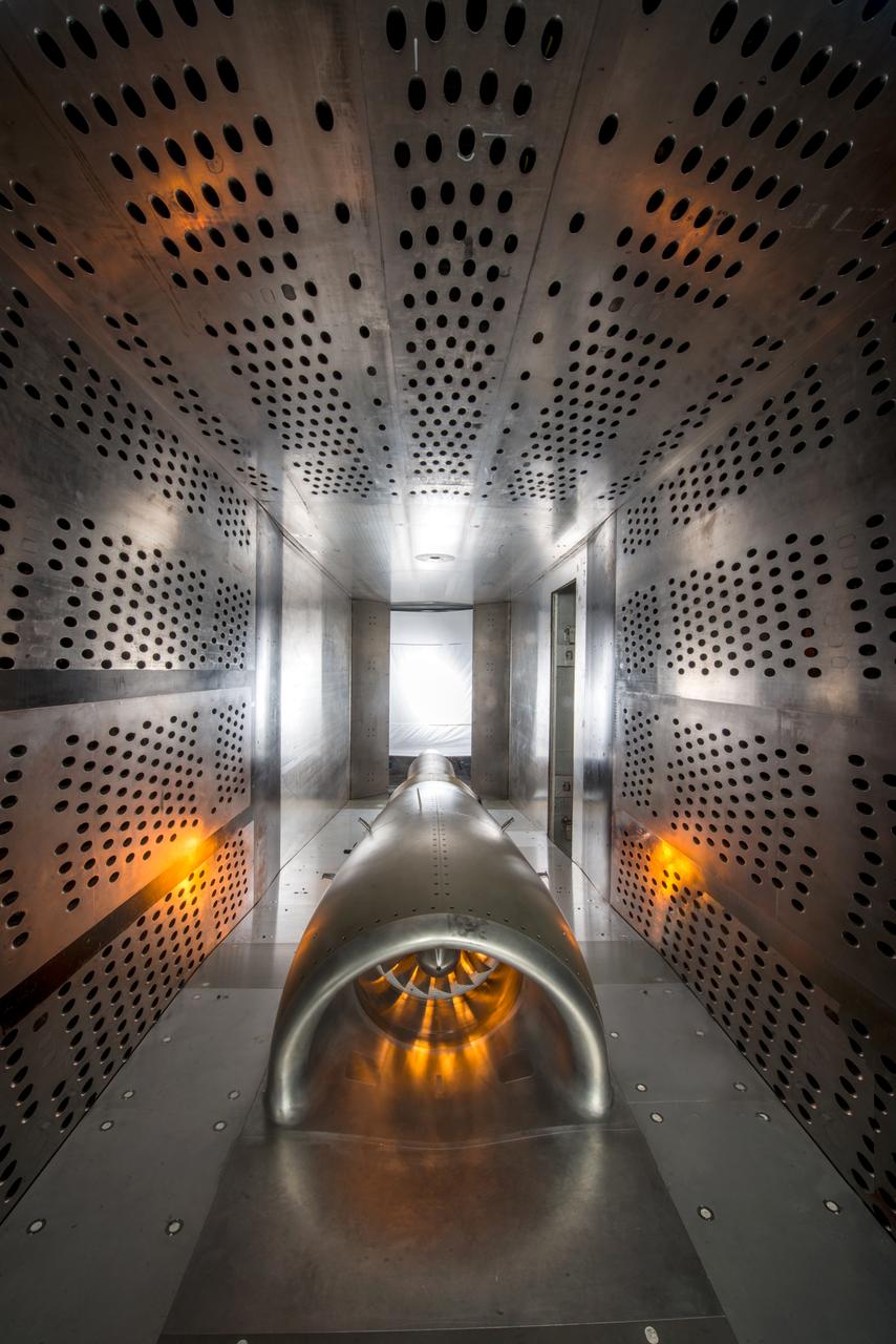
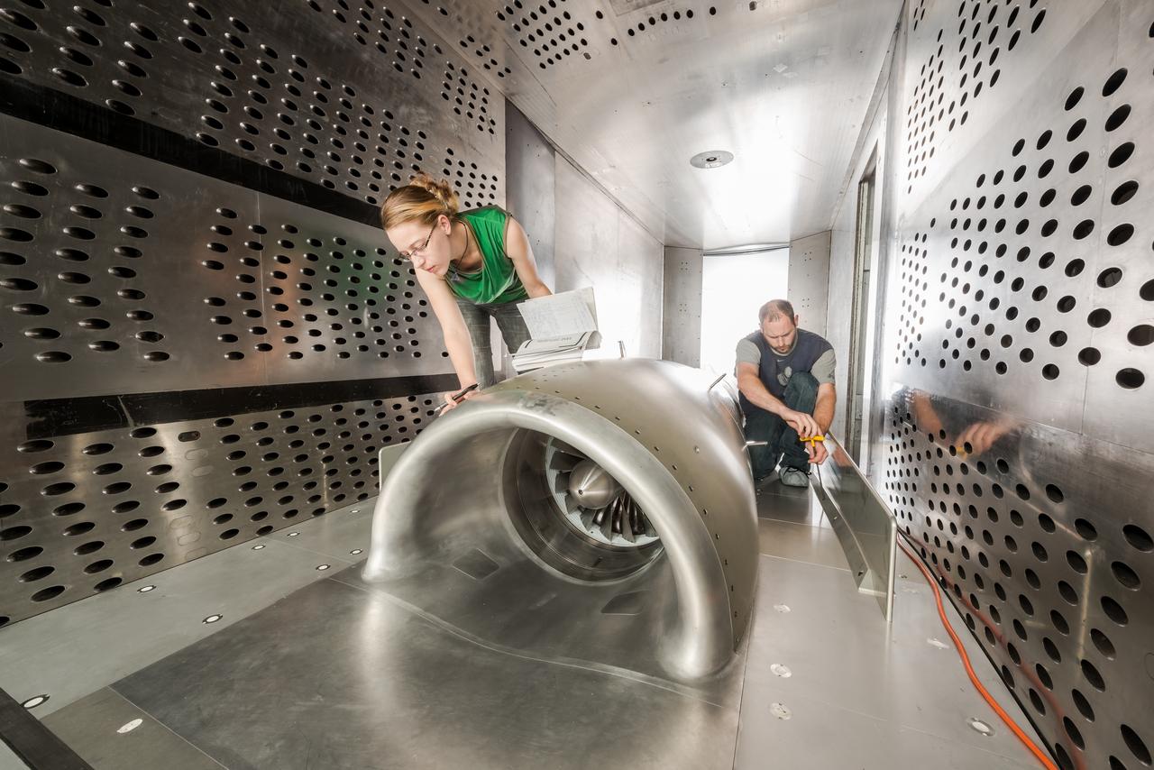
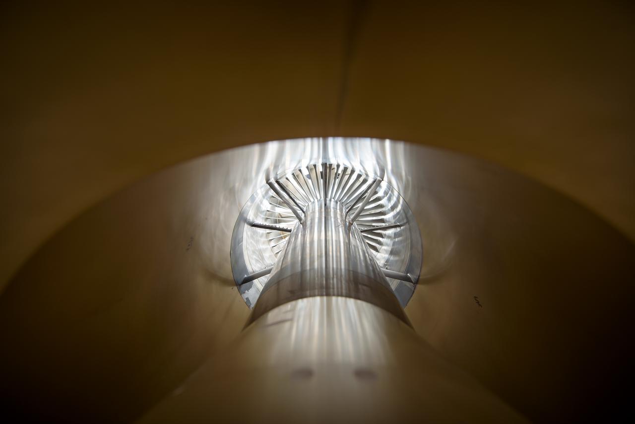
In an effort to improve fuel efficiency, NASA and the aircraft industry are rethinking aircraft design. Inside the 8' x 6' wind tunnel at NASA Glenn, engineers recently tested a fan and inlet design, commonly called a propulsor, which could use four to eight percent less fuel than today's advanced aircraft.
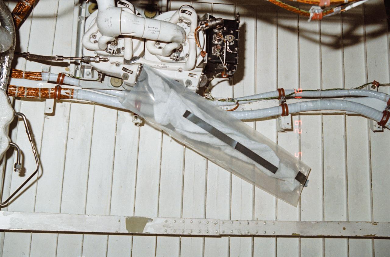
During STS-32, onboard Columbia, Orbiter Vehicle (OV) 102, a leakage problem at environmental control and life support system (ECLSS) air revitalization system (ARS) humidity separator A below the middeck is solved with a plastic bag and a towel. The towel inserted inside a plastic bag absorbed the water that had collected at the separator inlet.
In an effort to improve fuel efficiency, NASA and the aircraft industry are rethinking aircraft design. Inside the 8' x 6' wind tunnel at NASA Glenn, engineers recently tested a fan and inlet design, commonly called a propulsor, which could use four to eight percent less fuel than today's advanced aircraft.
In an effort to improve fuel efficiency, NASA and the aircraft industry are rethinking aircraft design. Inside the 8' x 6' wind tunnel at NASA Glenn, engineers recently tested a fan and inlet design, commonly called a propulsor, which could use four to eight percent less fuel than today's advanced aircraft.
In an effort to improve fuel efficiency, NASA and the aircraft industry are rethinking aircraft design. Inside the 8' x 6' wind tunnel at NASA Glenn, engineers recently tested a fan and inlet design, commonly called a propulsor, which could use four to eight percent less fuel than today's advanced aircraft.
In an effort to improve fuel efficiency, NASA and the aircraft industry are rethinking aircraft design. Inside the 8' x 6' wind tunnel at NASA Glenn, engineers recently tested a fan and inlet design, commonly called a propulsor, which could use four to eight percent less fuel than today's advanced aircraft.
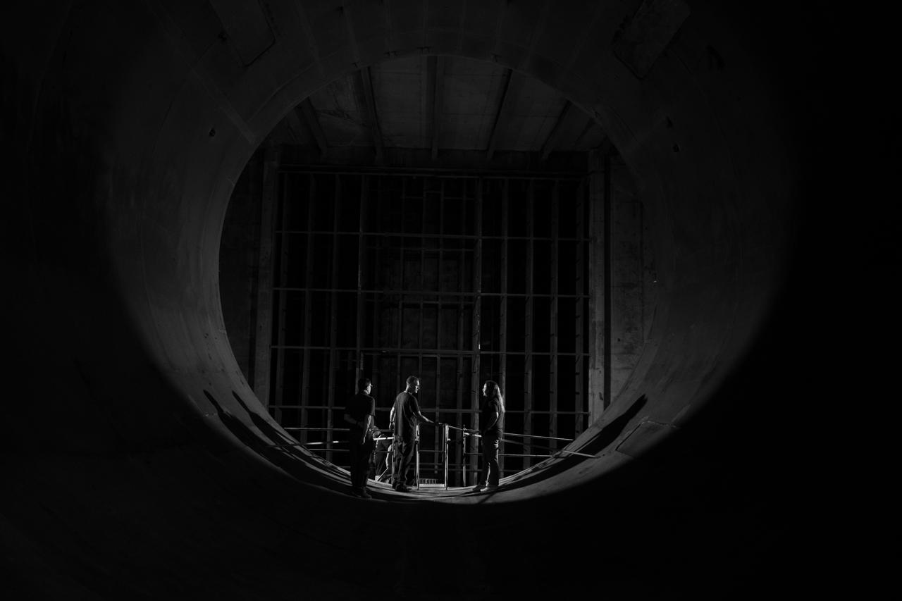
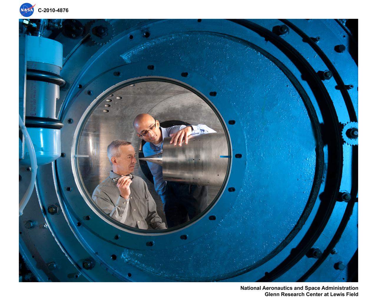
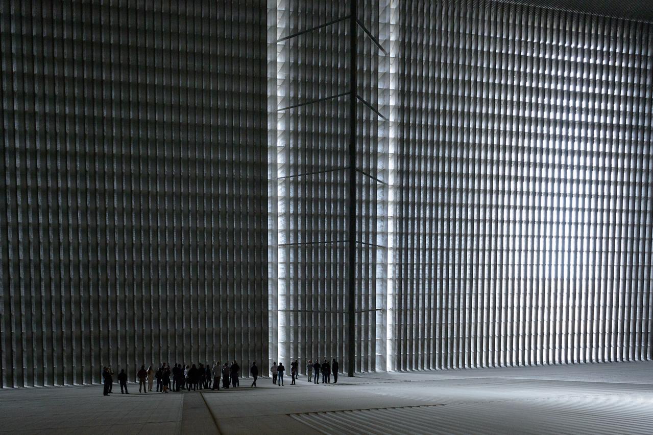
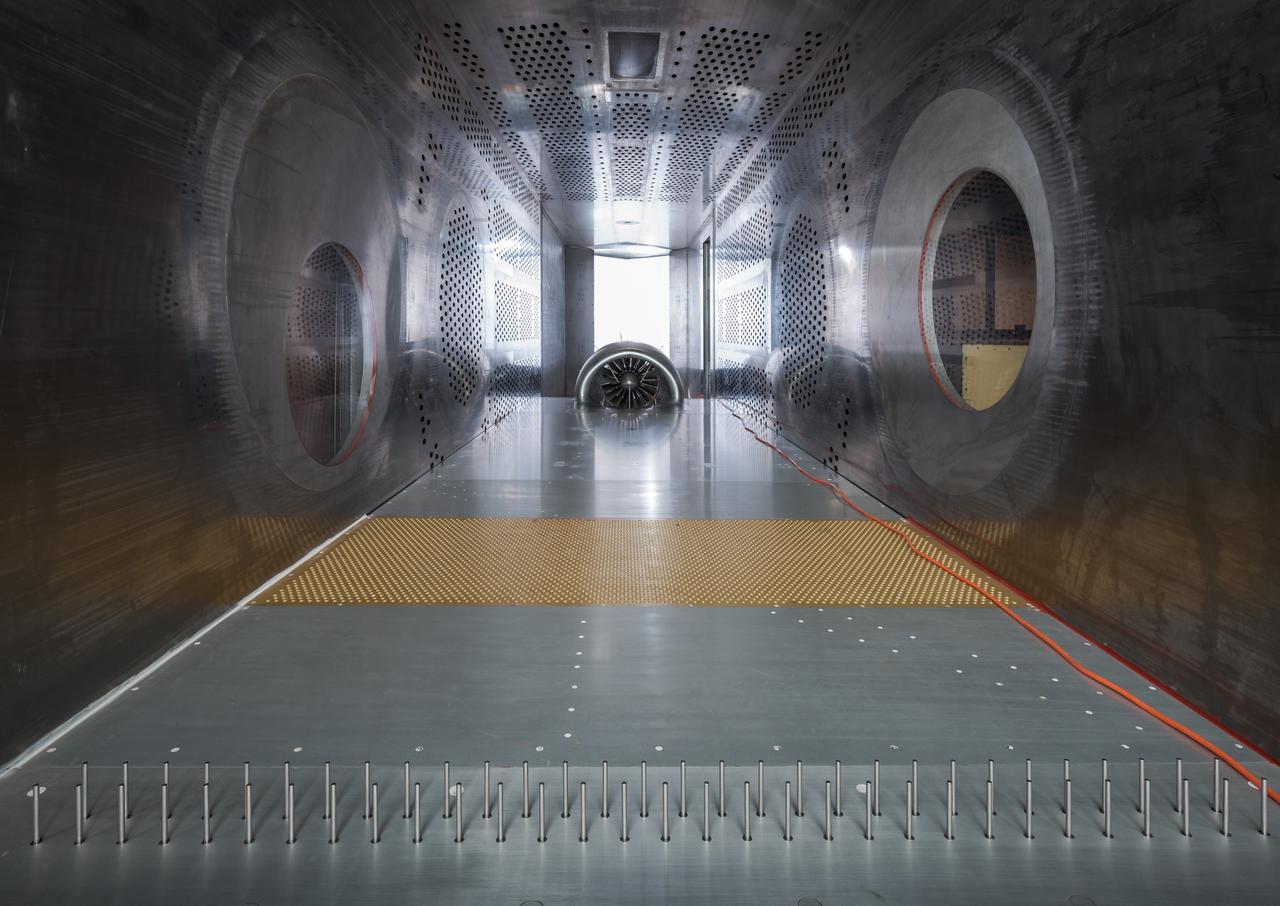
The 10- by 10-Foot Supersonic Wind Tunnel (10×10) is the largest and fastest wind tunnel facility at NASA’s Glenn Research Center and is specifically designed to test supersonic propulsion components from inlets and nozzles to full-scale jet and rocket engines.
In an effort to improve fuel efficiency, NASA and the aircraft industry are rethinking aircraft design. Inside the 8' x 6' wind tunnel at NASA Glenn, engineers recently tested a fan and inlet design, commonly called a propulsor, which could use four to eight percent less fuel than today's advanced aircraft.
In an effort to improve fuel efficiency, NASA and the aircraft industry are rethinking aircraft design. Inside the 8' x 6' wind tunnel at NASA Glenn, engineers recently tested a fan and inlet design, commonly called a propulsor, which could use four to eight percent less fuel than today's advanced aircraft.

In an effort to improve fuel efficiency, NASA and the aircraft industry are rethinking aircraft design. Inside the 8' x 6' wind tunnel at NASA Glenn, engineers recently tested a fan and inlet design, commonly called a propulsor, which could use four to eight percent less fuel than today's advanced aircraft.

In an effort to improve fuel efficiency, NASA and the aircraft industry are rethinking aircraft design. Inside the 8' x 6' wind tunnel at NASA Glenn, engineers recently tested a fan and inlet design, commonly called a propulsor, which could use four to eight percent less fuel than today's advanced aircraft.
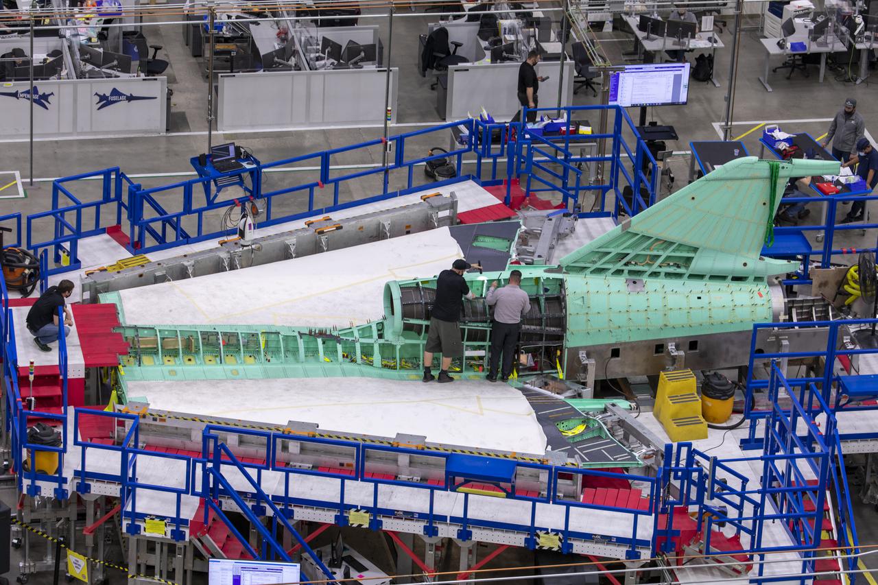
This overhead shot of the X-59 assembly during Spring 2021 shows assembly with technicians working at the engine inlet section where the engine will be located on the aircraft. Lockheed Martin Photography By Garry Tice 1011 Lockheed Way, Palmdale, Ca. 93599 Event: Manufacture Area From Above Date: 3/30/2021

This illustration shows Jezero Crater — the landing site of the Mars 2020 Perseverance rover — as it may have looked billions of years go on Mars, when it was a lake. An inlet and outlet are also visible on either side of the lake. A key objective for Perseverance's mission on Mars is astrobiology, including the search for signs of ancient microbial life. The rover will characterize the planet's geology and past climate, pave the way for human exploration of the Red Planet, and be the first mission to collect and cache Martian rock and regolith (broken rock and dust). Subsequent missions, currently under consideration by NASA in cooperation with the European Space Agency, would send spacecraft to Mars to collect these cached samples from the surface and return them to Earth for in-depth analysis. https://photojournal.jpl.nasa.gov/catalog/PIA24172