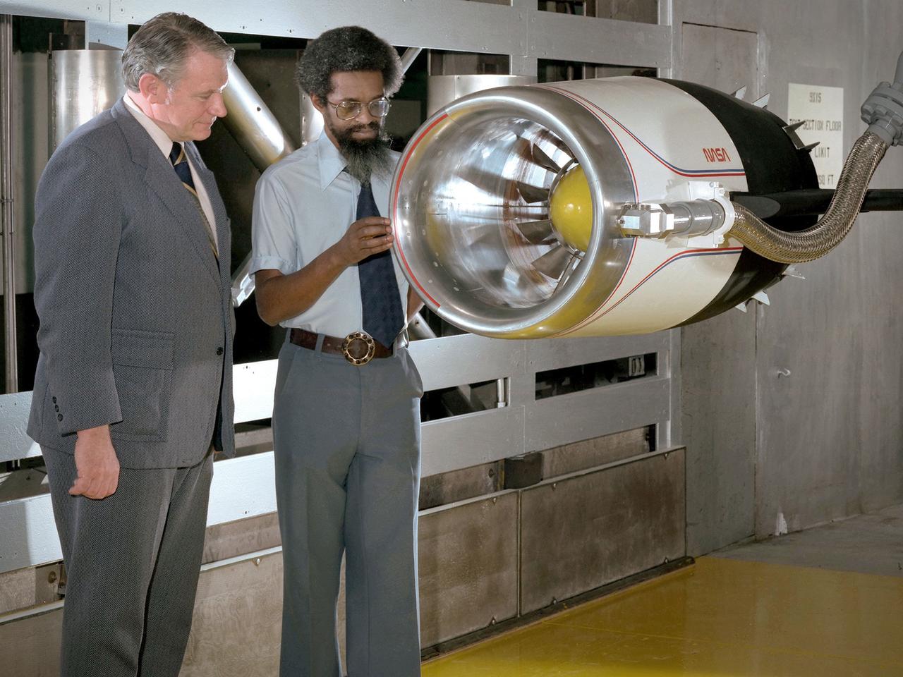
Center Director John McCarthy, left, and researcher Al Johns pose with a one-third scale model of a Grumman Aerospace tilt engine nacelle for Vertical and Short Takeoff and Landing (V/STOL) in the 9- by 15-Foot Low Speed Wind Tunnel at the National Aeronautics and Space Administration (NASA) Lewis Research Center. Lewis researchers had been studying tilt nacelle and inlet issues for several years. One area of concern was the inlet flow separation during the transition from horizontal to vertical flight. The separation of air flow from the inlet’s internal components could significantly stress the fan blades or cause a loss of thrust. In 1978 NASA researchers Robert Williams and Al Johns teamed with Grumman’s H.C. Potonides to develop a series of tests in the Lewis 9- by 15-foot tunnel to study a device designed to delay the flow separation by blowing additional air into the inlet. A jet of air, supplied through the hose on the right, was blown over the inlet surfaces. The researchers verified that the air jet slowed the flow separation. They found that the blowing on boundary layer control resulted in a doubling of the angle-of-attack and decreases in compressor blade stresses and fan distortion. The tests were the first time the concept of blowing air for boundary layer control was demonstrated. Boundary layer control devices like this could result in smaller and lighter V/STOL inlets.
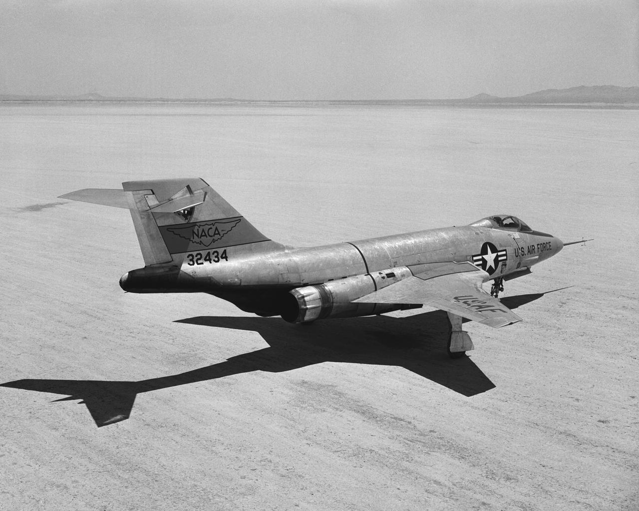
F-101A Rear quarter view on Edwards Lakebed. Aug. 10, 1956
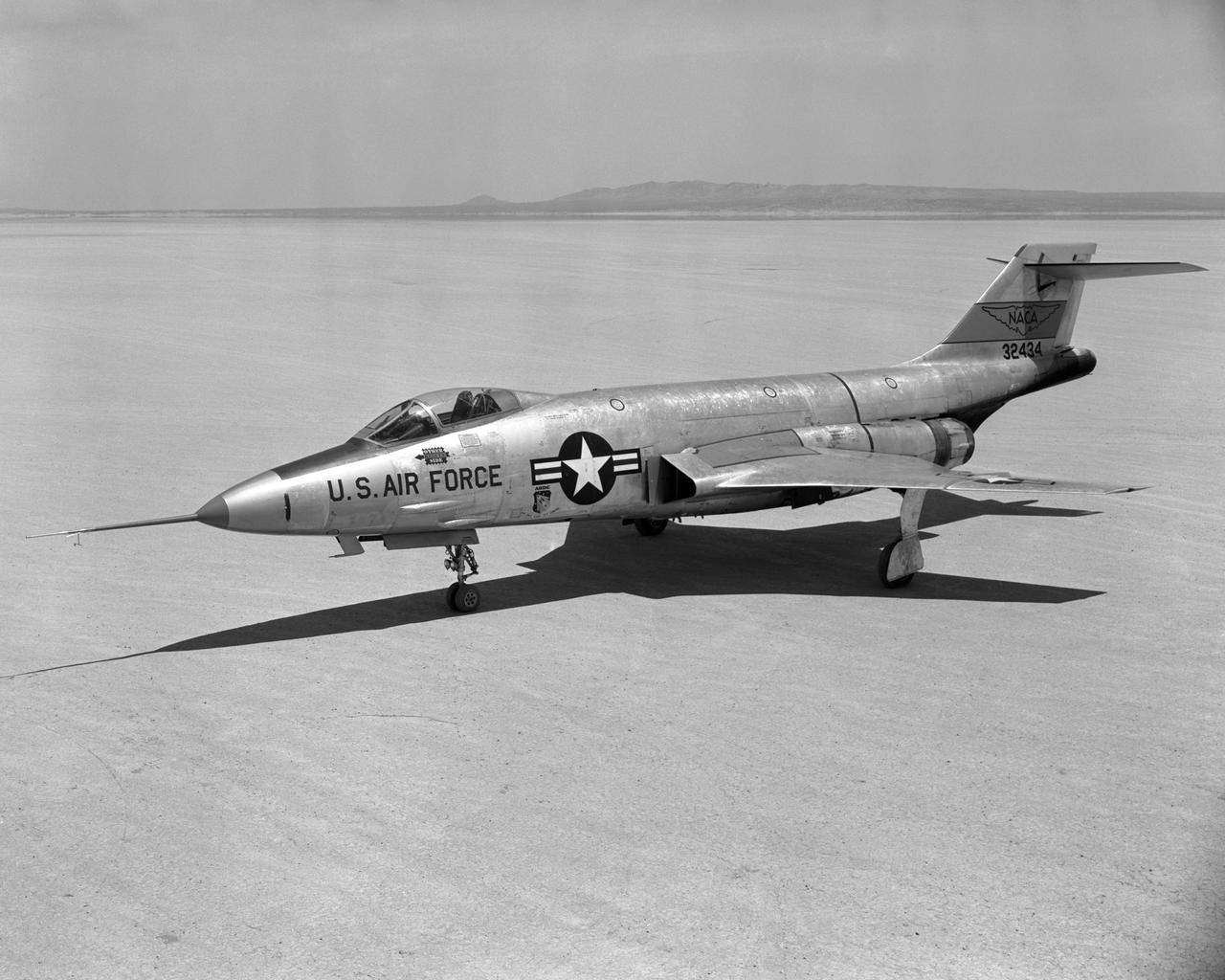
F-101A Front quarter view on Edwards Lakebed Aug. 10, 1956
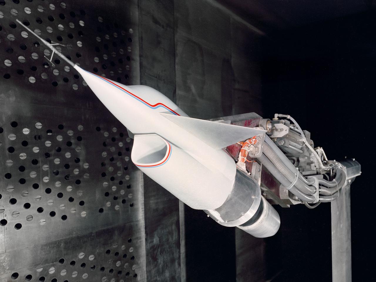
A Highly Maneuverable Aircraft Technology (HiMAT) inlet model installed in the test section of the 8- by 6-Foot Supersonic Wind Tunnel at the National Aeronautics and Space Administration (NASA) Lewis Research Center. Engineers at the Ames Research Center, Dryden Flight Research Center, and Rockwell International designed two pilotless subscale HiMAT vehicles in the mid-1970s to study new design concepts for fighter aircraft in the transonic realm without risking the lives of test pilots. The aircraft used sophisticated technologies such as advanced aerodynamics, composite materials, digital integrated propulsion control, and digital fly-by-wire control systems. In late 1977 NASA Lewis studied the HiMAT’s General Electric J85-21 jet engine in the Propulsion Systems Laboratory. The researchers charted the inlet quality with various combinations anti-distortion screens. HiMAT employed a relatively short and curved inlet compared to actual fighter jets. In the spring of 1979, Larry Smith led an in-depth analysis of the HiMAT inlet in the 8- by 6 tunnel. The researchers installed vortex generators to battle flow separation in the diffuser. The two HiMAT aircraft performed 11 hours of flying over the course of 26 missions from mid-1979 to January 1983 at Dryden and Ames. Although the HiMAT vehicles were considered to be overly complex and expensive, the program yielded a wealth of data that would validate computer-based design tools.
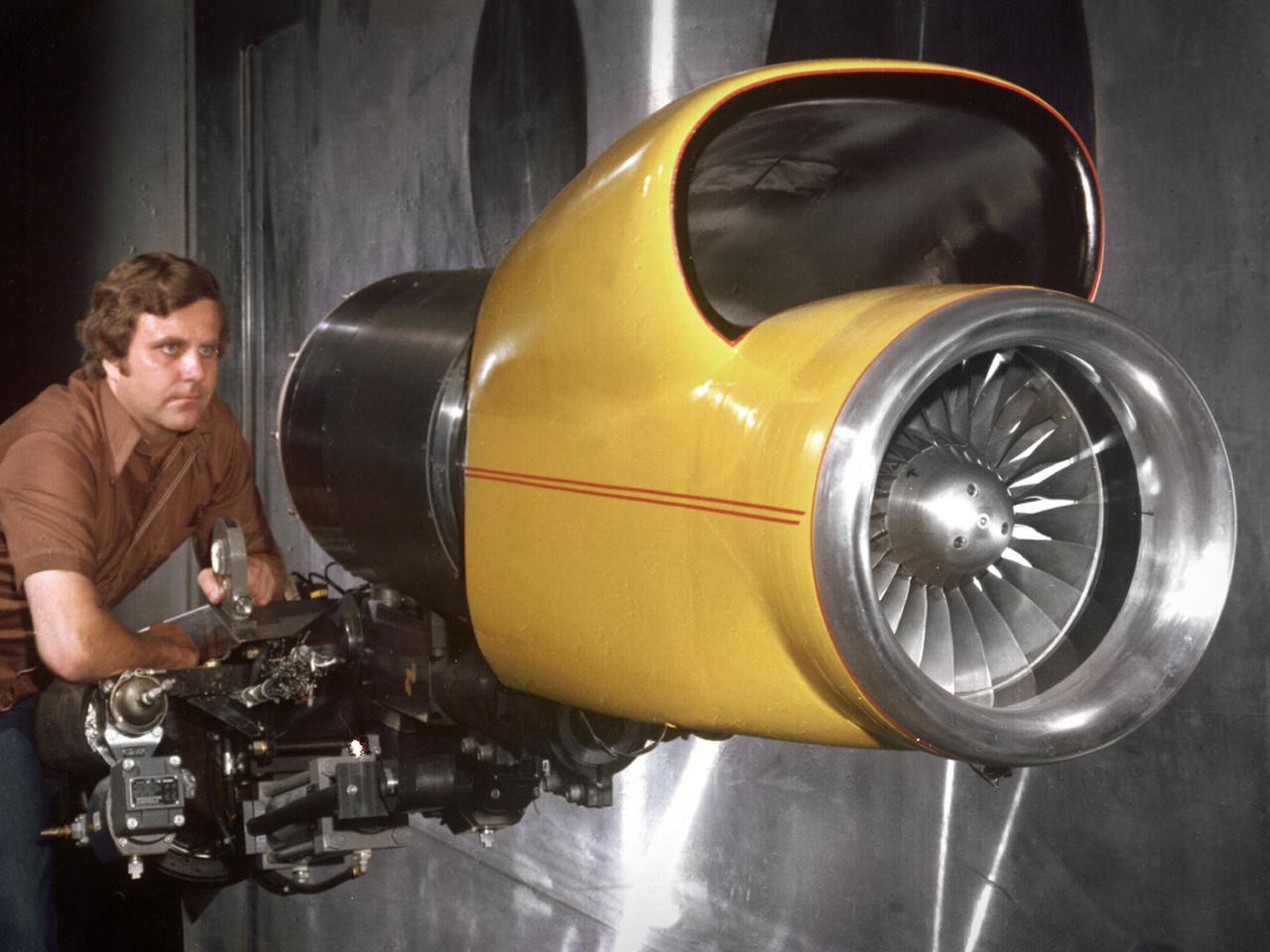
A technician checks a 0.25-scale engine model of a Vought Corporation V-530 engine in the test section of the 10- by 10-Foot Supersonic Wind Tunnel at the National Aeronautics and Space Administration (NASA) Lewis Research Center. Vought created a low-drag tandem-fan Vertical/Short and Takeoff and Landing (V/STOL) engine in the mid-1970s, designated as the V-530. The first fan on the tandem-fan engine was supplied with air through a traditional subsonic inlet, seen on the lower front of the engine. The air was exhausted through the nacelle during normal flight and directed down during takeoffs. The rear fan was supplied by the oval-shaped top inlet during all phases of the flight. The second fan exhausted its air through a rear vectorable nozzle. NASA Lewis and Vought partnered in the late 1970s to collect an array of inlet and nozzle design information on the tandem fan engines for the Navy. Vought created this .25-scale model of the V-530 for extensive testing in Lewis' 10- by 10-foot tunnel. During an early series of tests, the front fan was covered, and a turbofan simulator was used to supply air to the rear fan. The researchers then analyzed the performance of only the front fan inlet. During the final series of tests, the flow from the front fan was used to supply airflow to the rear fan. The researchers studied the inlet's recovery, distortion, and angle-of-attack limits over various flight conditions.