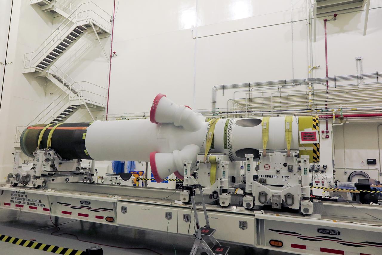
The launch abort motor is integrated with the jettison motor for Orion’s launch abort system (LAS) for Artemis II, inside the Launch Abort System Facility at NASA’s Kennedy Space Center in Florida on April 15, 2020. The launch abort and jettison motors are two of three motors on the LAS. The LAS will be positioned atop the Orion crew module and is designed to protect astronauts if a problem arises during launch by pulling the spacecraft away from a failing rocket. Artemis II will take the first humans in orbit around the Moon in the 21st century.
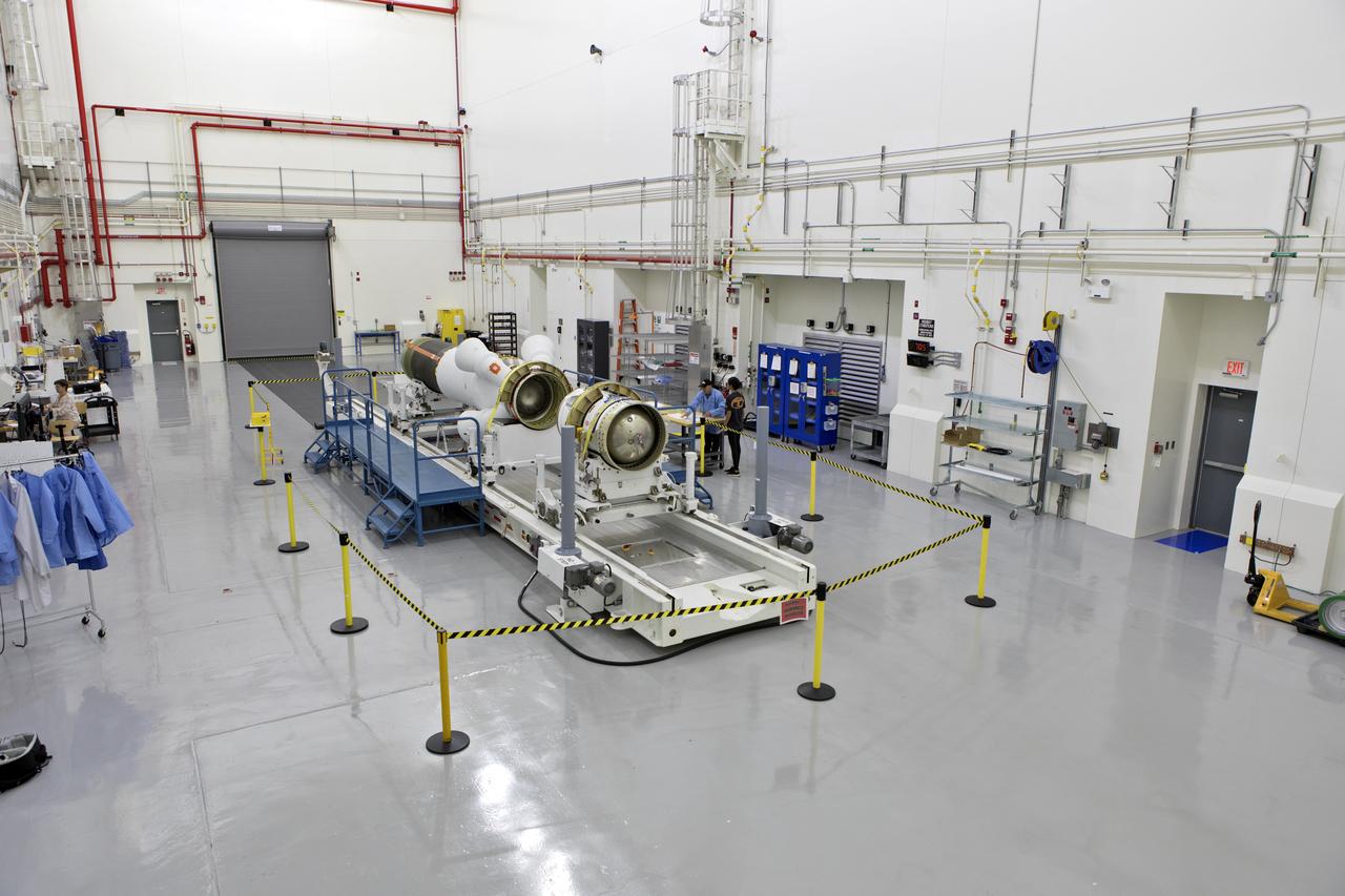
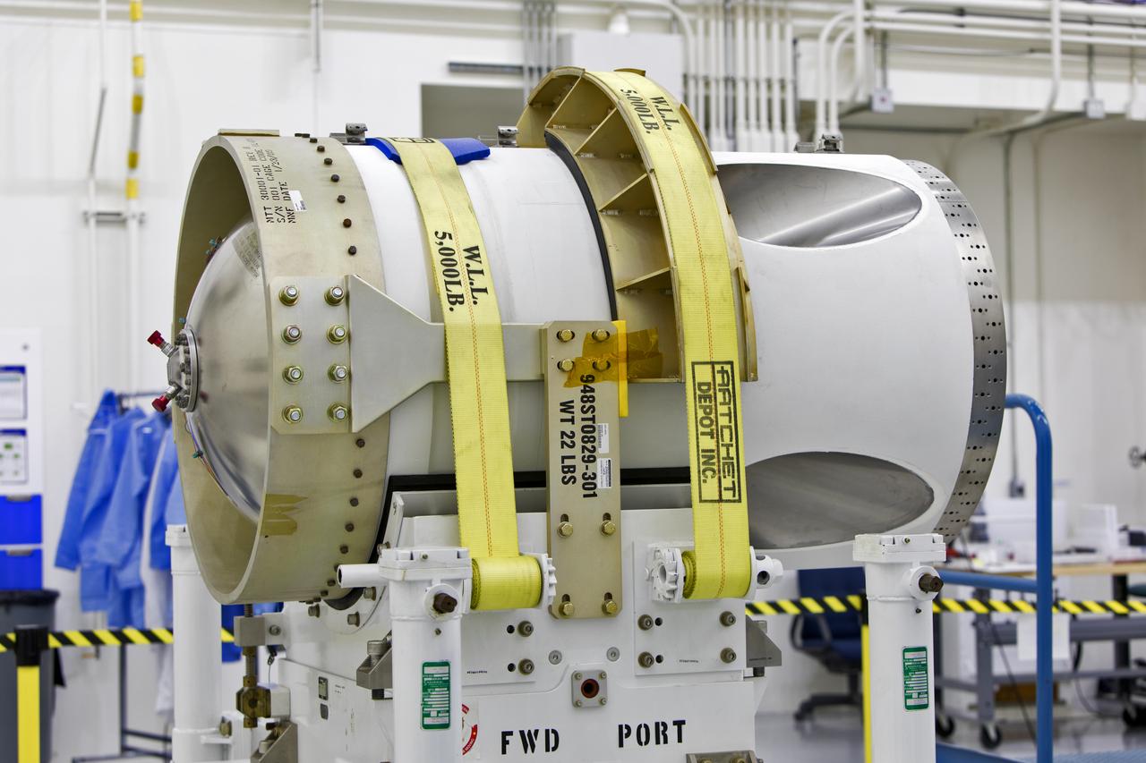
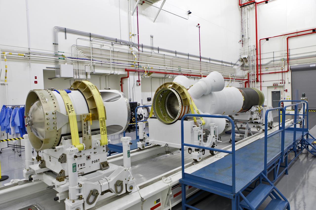
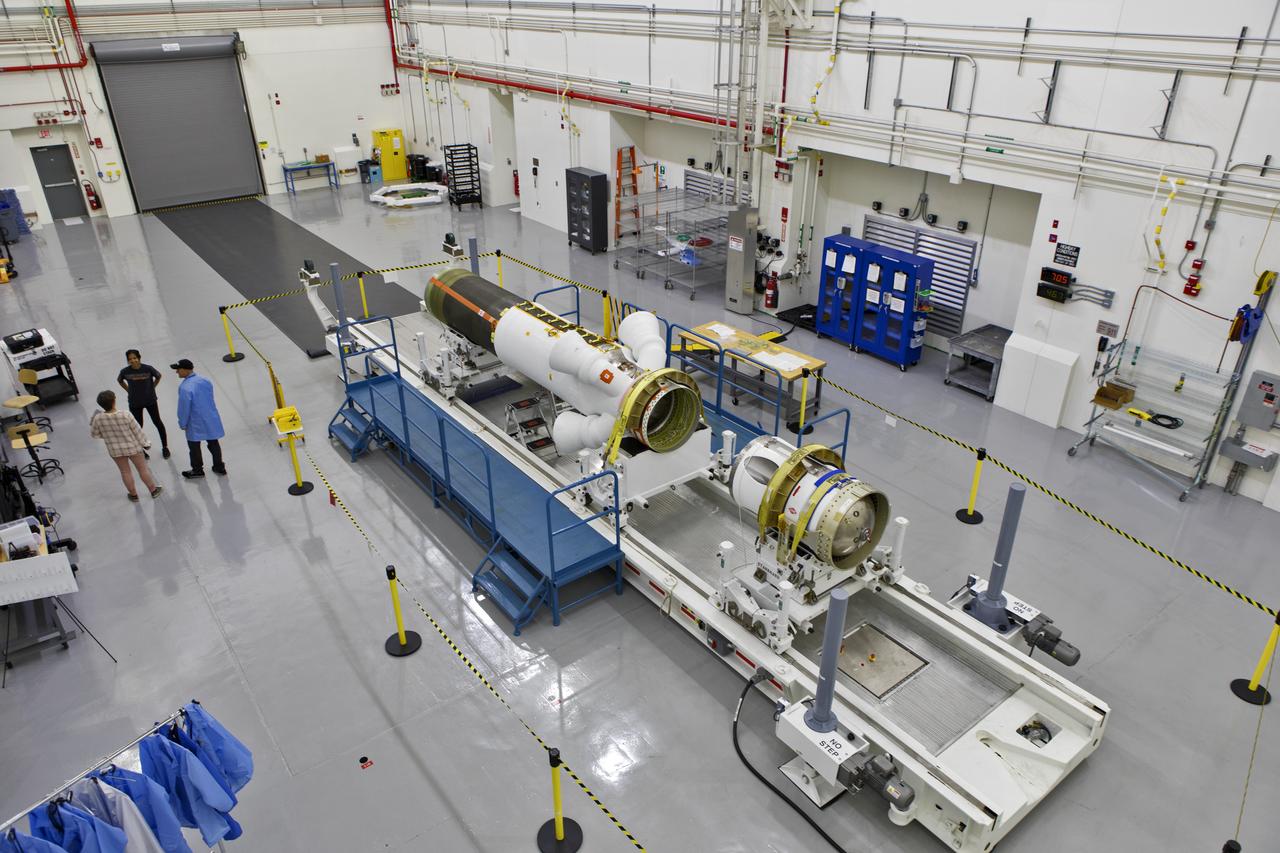
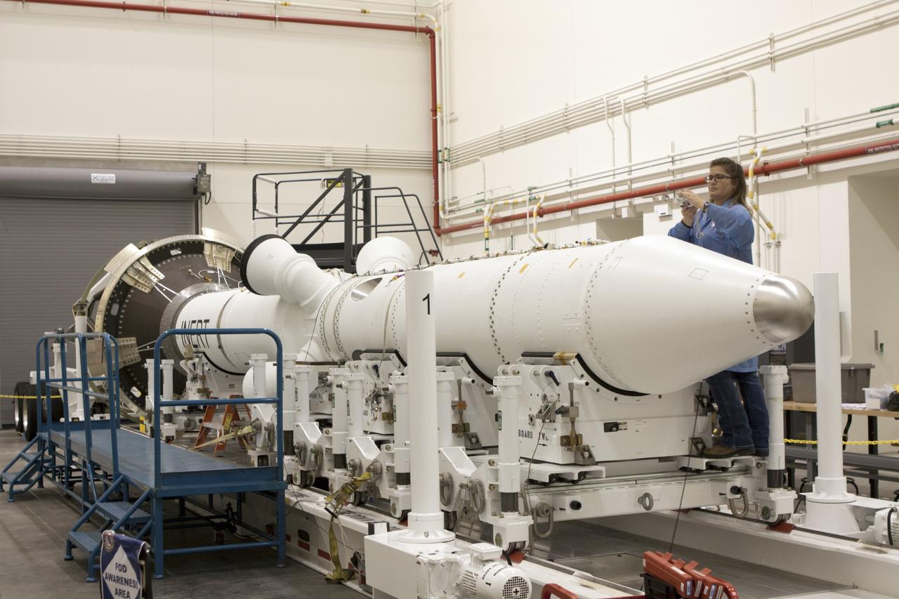
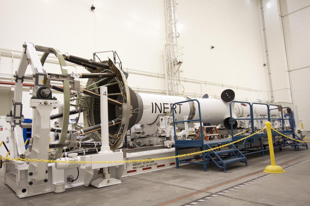
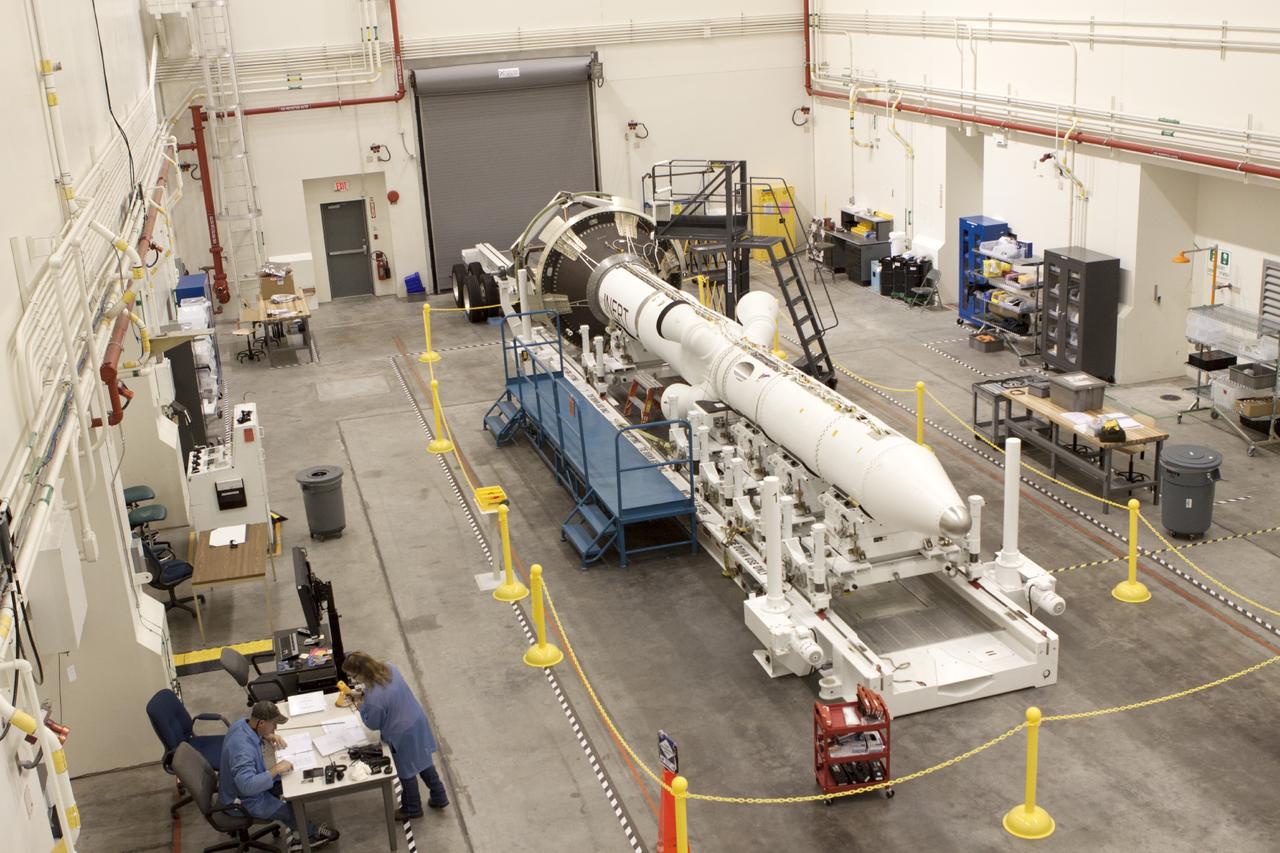
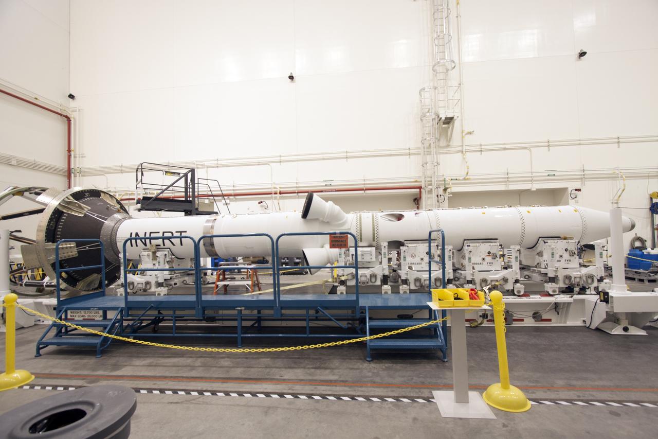
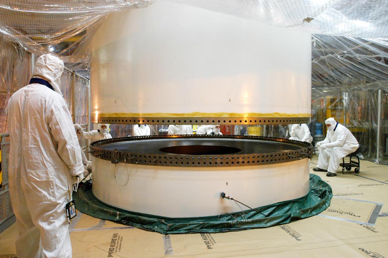
The jettison motor for Orion’s Launch Abort System (LAS) is shown inside the Launch Abort System Facility (LASF) at NASA’s Kennedy Space Center in Florida. The motor, which arrived at Kennedy on Sept. 10, 2018, will be stored in the LASF until processing for a full-stress test of the LAS called Ascent Abort-2 (AA-2), scheduled for April 2019. Designed and built by NASA and Lockheed Martin, the LAS will protect astronauts if a problem arises during launch by pulling the spacecraft away from a failing rocket. The jettison motor is one of three solid propellant rocket motors in the LAS (the abort motor and attitude control motor are the other two). The jettison motor will pull the LAS away from the crew module, allowing Orion’s parachutes to deploy and the spacecraft to safely land in the ocean.
The jettison motor for Orion’s Launch Abort System (LAS) is shown inside the Launch Abort System Facility (LASF) at NASA’s Kennedy Space Center in Florida. The motor, which arrived at Kennedy on Sept. 10, 2018, will be stored in the LASF until processing for a full-stress test of the LAS called Ascent Abort-2 (AA-2), scheduled for April 2019. Designed and built by NASA and Lockheed Martin, the LAS will protect astronauts if a problem arises during launch by pulling the spacecraft away from a failing rocket. The jettison motor is one of three solid propellant rocket motors in the LAS (the abort motor and attitude control motor are the other two). The jettison motor will pull the LAS away from the crew module, allowing Orion’s parachutes to deploy and the spacecraft to safely land in the ocean.
The jettison motor for Orion’s Launch Abort System (LAS) is shown inside the Launch Abort System Facility (LASF) at NASA’s Kennedy Space Center in Florida. The motor, which arrived at Kennedy on Sept. 10, 2018, will be stored in the LASF until processing for a full-stress test of the LAS called Ascent Abort-2 (AA-2), scheduled for April 2019. Designed and built by NASA and Lockheed Martin, the LAS will protect astronauts if a problem arises during launch by pulling the spacecraft away from a failing rocket. The jettison motor is one of three solid propellant rocket motors in the LAS (the abort motor and attitude control motor are the other two). The jettison motor will pull the LAS away from the crew module, allowing Orion’s parachutes to deploy and the spacecraft to safely land in the ocean.
The jettison motor for Orion’s Launch Abort System (LAS) is shown inside the Launch Abort System Facility (LASF) at NASA’s Kennedy Space Center in Florida. The motor, which arrived at Kennedy on Sept. 10, 2018, will be stored in the LASF until processing for a full-stress test of the LAS called Ascent Abort-2 (AA-2), scheduled for April 2019. Designed and built by NASA and Lockheed Martin, the LAS will protect astronauts if a problem arises during launch by pulling the spacecraft away from a failing rocket. The jettison motor is one of three solid propellant rocket motors in the LAS (the abort motor and attitude control motor are the other two). The jettison motor will pull the LAS away from the crew module, allowing Orion’s parachutes to deploy and the spacecraft to safely land in the ocean.
The jettison motor for Orion’s Launch Abort System (LAS) is shown inside the Launch Abort System Facility (LASF) at NASA’s Kennedy Space Center in Florida. The motor, which arrived at Kennedy on Sept. 10, 2018, will be stored in the LASF until processing for a full-stress test of the LAS called Ascent Abort-2 (AA-2), scheduled for April 2019. Designed and built by NASA and Lockheed Martin, the LAS will protect astronauts if a problem arises during launch by pulling the spacecraft away from a failing rocket. The jettison motor is one of three solid propellant rocket motors in the LAS (the abort motor and attitude control motor are the other two). The jettison motor will pull the LAS away from the crew module, allowing Orion’s parachutes to deploy and the spacecraft to safely land in the ocean.
The jettison motor for Orion’s Launch Abort System (LAS) is shown inside the Launch Abort System Facility (LASF) at NASA’s Kennedy Space Center in Florida. The motor, which arrived at Kennedy on Sept. 10, 2018, will be stored in the LASF until processing for a full-stress test of the LAS called Ascent Abort-2 (AA-2), scheduled for April 2019. Designed and built by NASA and Lockheed Martin, the LAS will protect astronauts if a problem arises during launch by pulling the spacecraft away from a failing rocket. The jettison motor is one of three solid propellant rocket motors in the LAS (the abort motor and attitude control motor are the other two). The jettison motor will pull the LAS away from the crew module, allowing Orion’s parachutes to deploy and the spacecraft to safely land in the ocean.
The jettison motor for Orion’s Launch Abort System (LAS) is shown inside the Launch Abort System Facility (LASF) at NASA’s Kennedy Space Center in Florida. The motor, which arrived at Kennedy on Sept. 10, 2018, will be stored in the LASF until processing for a full-stress test of the LAS called Ascent Abort-2 (AA-2), scheduled for April 2019. Designed and built by NASA and Lockheed Martin, the LAS will protect astronauts if a problem arises during launch by pulling the spacecraft away from a failing rocket. The jettison motor is one of three solid propellant rocket motors in the LAS (the abort motor and attitude control motor are the other two). The jettison motor will pull the LAS away from the crew module, allowing Orion’s parachutes to deploy and the spacecraft to safely land in the ocean.
The jettison motor for Orion’s Launch Abort System (LAS) is shown inside the Launch Abort System Facility (LASF) at NASA’s Kennedy Space Center in Florida. The motor, which arrived at Kennedy on Sept. 10, 2018, will be stored in the LASF until processing for a full-stress test of the LAS called Ascent Abort-2 (AA-2), scheduled for April 2019. Designed and built by NASA and Lockheed Martin, the LAS will protect astronauts if a problem arises during launch by pulling the spacecraft away from a failing rocket. The jettison motor is one of three solid propellant rocket motors in the LAS (the abort motor and attitude control motor are the other two). The jettison motor will pull the LAS away from the crew module, allowing Orion’s parachutes to deploy and the spacecraft to safely land in the ocean.
The jettison motor for Orion’s Launch Abort System (LAS) is shown inside the Launch Abort System Facility (LASF) at NASA’s Kennedy Space Center in Florida. The motor, which arrived at Kennedy on Sept. 10, 2018, will be stored in the LASF until processing for a full-stress test of the LAS called Ascent Abort-2 (AA-2), scheduled for April 2019. Designed and built by NASA and Lockheed Martin, the LAS will protect astronauts if a problem arises during launch by pulling the spacecraft away from a failing rocket. The jettison motor is one of three solid propellant rocket motors in the LAS (the abort motor and attitude control motor are the other two). The jettison motor will pull the LAS away from the crew module, allowing Orion’s parachutes to deploy and the spacecraft to safely land in the ocean.
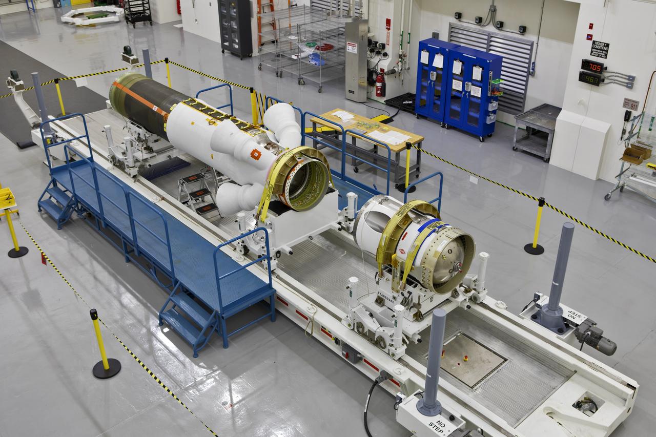
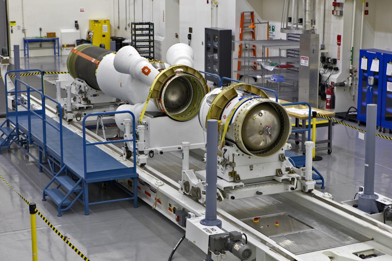
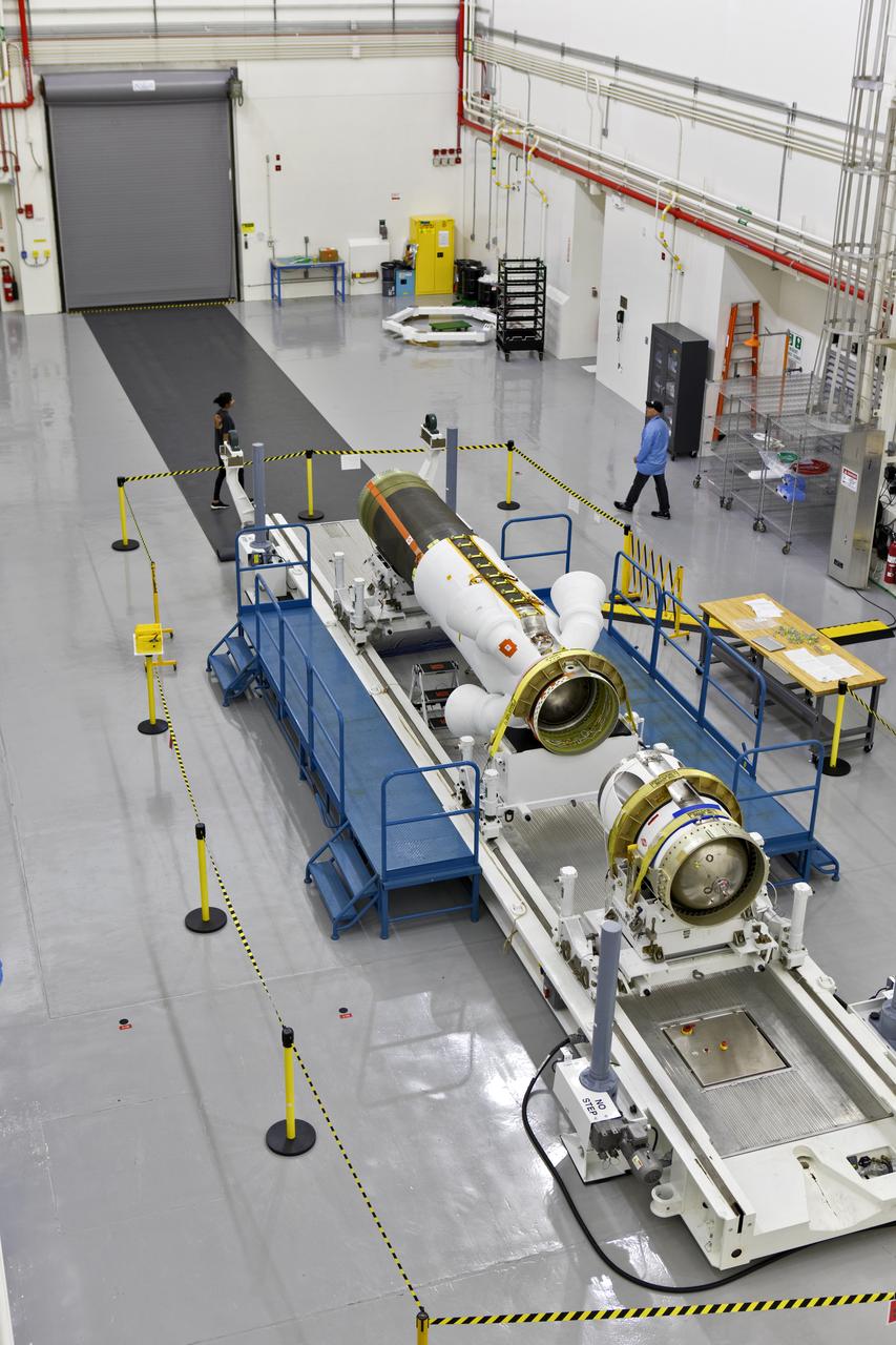
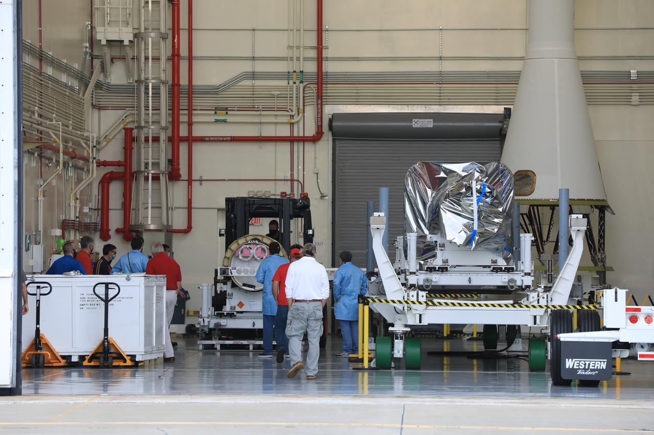
The launch abort motor is integrated with the jettison motor for Orion’s launch abort system (LAS) for Artemis II, inside the Launch Abort System Facility at NASA’s Kennedy Space Center in Florida on April 15, 2020. The launch abort and jettison motors are two of three motors on the LAS. The LAS will be positioned atop the Orion crew module and is designed to protect astronauts if a problem arises during launch by pulling the spacecraft away from a failing rocket. Artemis II will take the first humans in orbit around the Moon in the 21st century. In view, at far left, is the Launch Abort System for Artemis I, the first uncrewed mission of Orion atop the Space Launch System rocket.
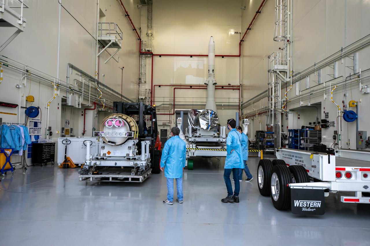
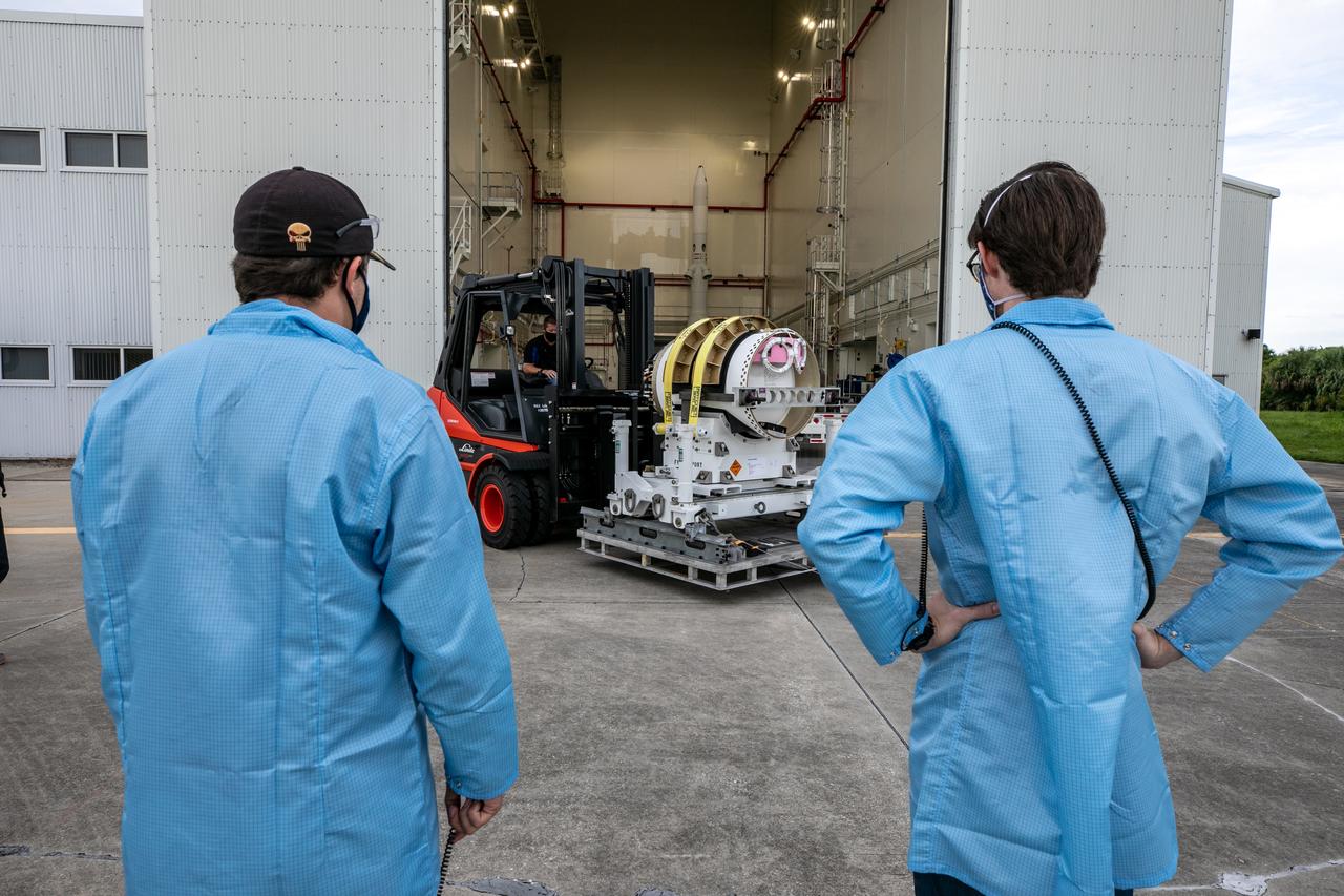
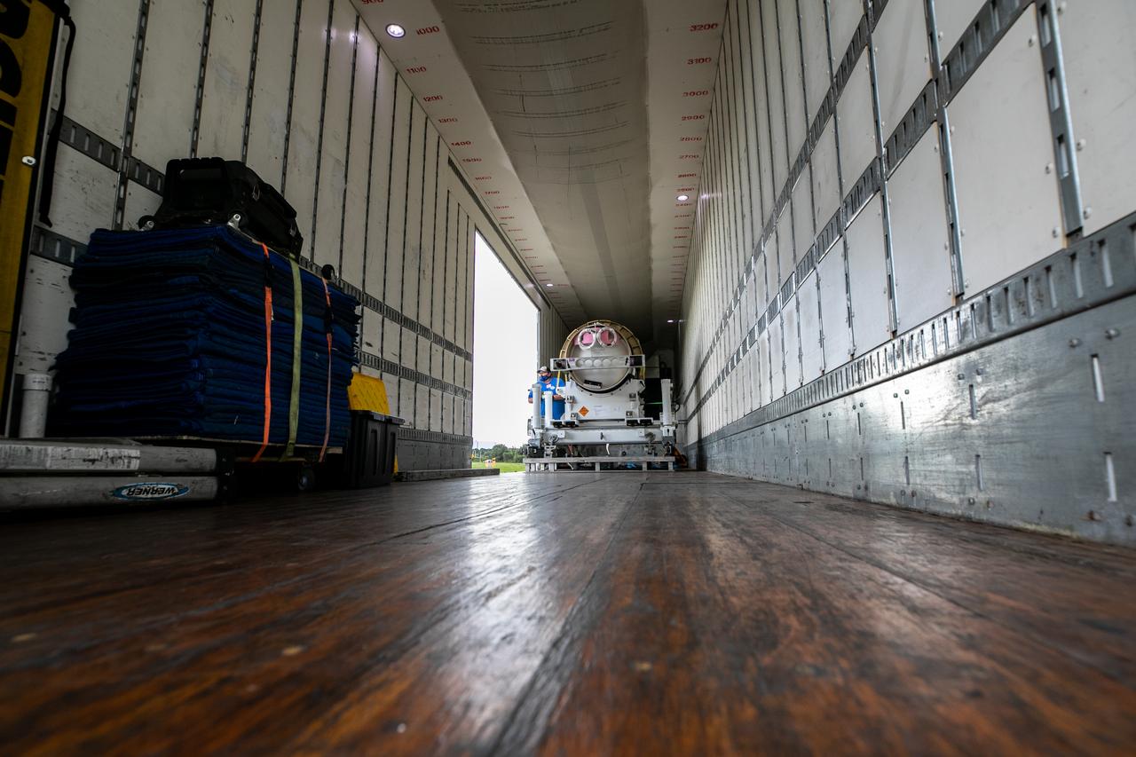
The last of three motors required to assemble the Launch Abort System for NASA’s Artemis II mission, the attitude control motor (ACM), arrives at Kennedy Space Center in Florida on August 28. The attitude control motor (ACM) was delivered by truck from Northrop Grumman’s manufacturing facility in Maryland, to the Launch Abort System Facility (LASF) at Kennedy. During launch of Orion atop the agency’s Space Launch System rocket, the LAS motors work together to separate the spacecraft from the rocket in the unlikely event of an emergency during launch. The LAS includes three motors – the launch abort motor, the jettison motor, and the attitude control motor—that once activated, will steer the spacecraft carrying the astronauts to safety. The ACM operates to keep Orion’s crew module on a controlled flight path in the event it needs to jettison and steer away from the rocket. Artemis II is the first crewed flight in a series of increasingly complex missions to the Moon that will lay the foundation for exploration of Mars and beyond. Artemis II will confirm all of the Orion spacecraft’s systems operate as designed in the actual environment of deep space with astronauts aboard. As part of the Artemis program, NASA will send the first woman and next man to the Moon in 2024.
The last of three motors required to assemble the Launch Abort System for NASA’s Artemis II mission, the attitude control motor (ACM), arrives at Kennedy Space Center in Florida on August 28. The attitude control motor (ACM) was delivered by truck from Northrop Grumman’s manufacturing facility in Maryland, to the Launch Abort System Facility (LASF) at Kennedy. During launch of Orion atop the agency’s Space Launch System rocket, the LAS motors work together to separate the spacecraft from the rocket in the unlikely event of an emergency during launch. The LAS includes three motors – the launch abort motor, the jettison motor, and the attitude control motor—that once activated, will steer the spacecraft carrying the astronauts to safety. The ACM operates to keep Orion’s crew module on a controlled flight path in the event it needs to jettison and steer away from the rocket. Artemis II is the first crewed flight in a series of increasingly complex missions to the Moon that will lay the foundation for exploration of Mars and beyond. Artemis II will confirm all of the Orion spacecraft’s systems operate as designed in the actual environment of deep space with astronauts aboard. As part of the Artemis program, NASA will send the first woman and next man to the Moon in 2024.
The last of three motors required to assemble the Launch Abort System for NASA’s Artemis II mission, the attitude control motor (ACM), arrives at Kennedy Space Center in Florida on August 28. The attitude control motor (ACM) was delivered by truck from Northrop Grumman’s manufacturing facility in Maryland, to the Launch Abort System Facility (LASF) at Kennedy. During launch of Orion atop the agency’s Space Launch System rocket, the LAS motors work together to separate the spacecraft from the rocket in the unlikely event of an emergency during launch. The LAS includes three motors – the launch abort motor, the jettison motor, and the attitude control motor—that once activated, will steer the spacecraft carrying the astronauts to safety. The ACM operates to keep Orion’s crew module on a controlled flight path in the event it needs to jettison and steer away from the rocket. Artemis II is the first crewed flight in a series of increasingly complex missions to the Moon that will lay the foundation for exploration of Mars and beyond. Artemis II will confirm all of the Orion spacecraft’s systems operate as designed in the actual environment of deep space with astronauts aboard. As part of the Artemis program, NASA will send the first woman and next man to the Moon in 2024.
The last of three motors required to assemble the Launch Abort System for NASA’s Artemis II mission, the attitude control motor (ACM), arrives at Kennedy Space Center in Florida on August 28. The attitude control motor (ACM) was delivered by truck from Northrop Grumman’s manufacturing facility in Maryland, to the Launch Abort System Facility (LASF) at Kennedy. During launch of Orion atop the agency’s Space Launch System rocket, the LAS motors work together to separate the spacecraft from the rocket in the unlikely event of an emergency during launch. The LAS includes three motors – the launch abort motor, the jettison motor, and the attitude control motor—that once activated, will steer the spacecraft carrying the astronauts to safety. The ACM operates to keep Orion’s crew module on a controlled flight path in the event it needs to jettison and steer away from the rocket. Artemis II is the first crewed flight in a series of increasingly complex missions to the Moon that will lay the foundation for exploration of Mars and beyond. Artemis II will confirm all of the Orion spacecraft’s systems operate as designed in the actual environment of deep space with astronauts aboard. As part of the Artemis program, NASA will send the first woman and next man to the Moon in 2024.

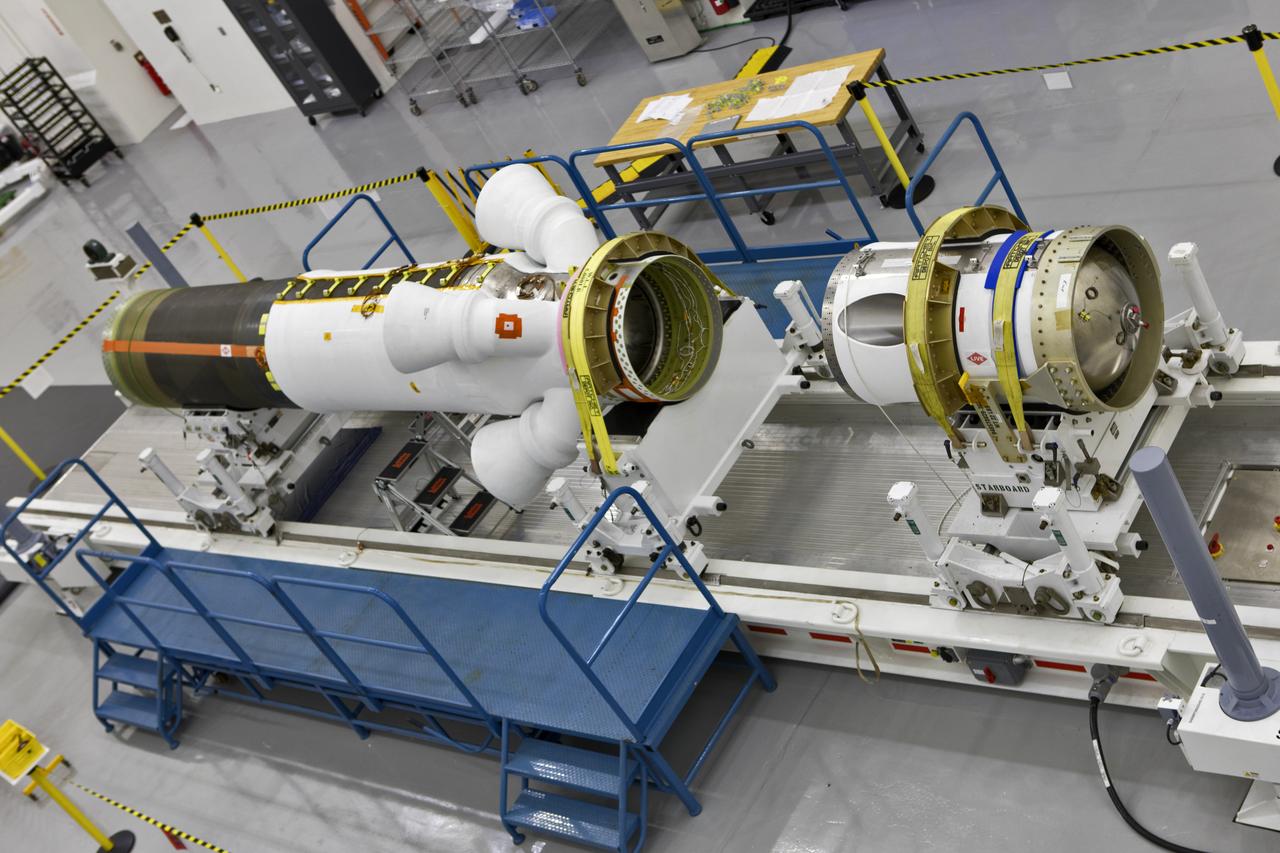
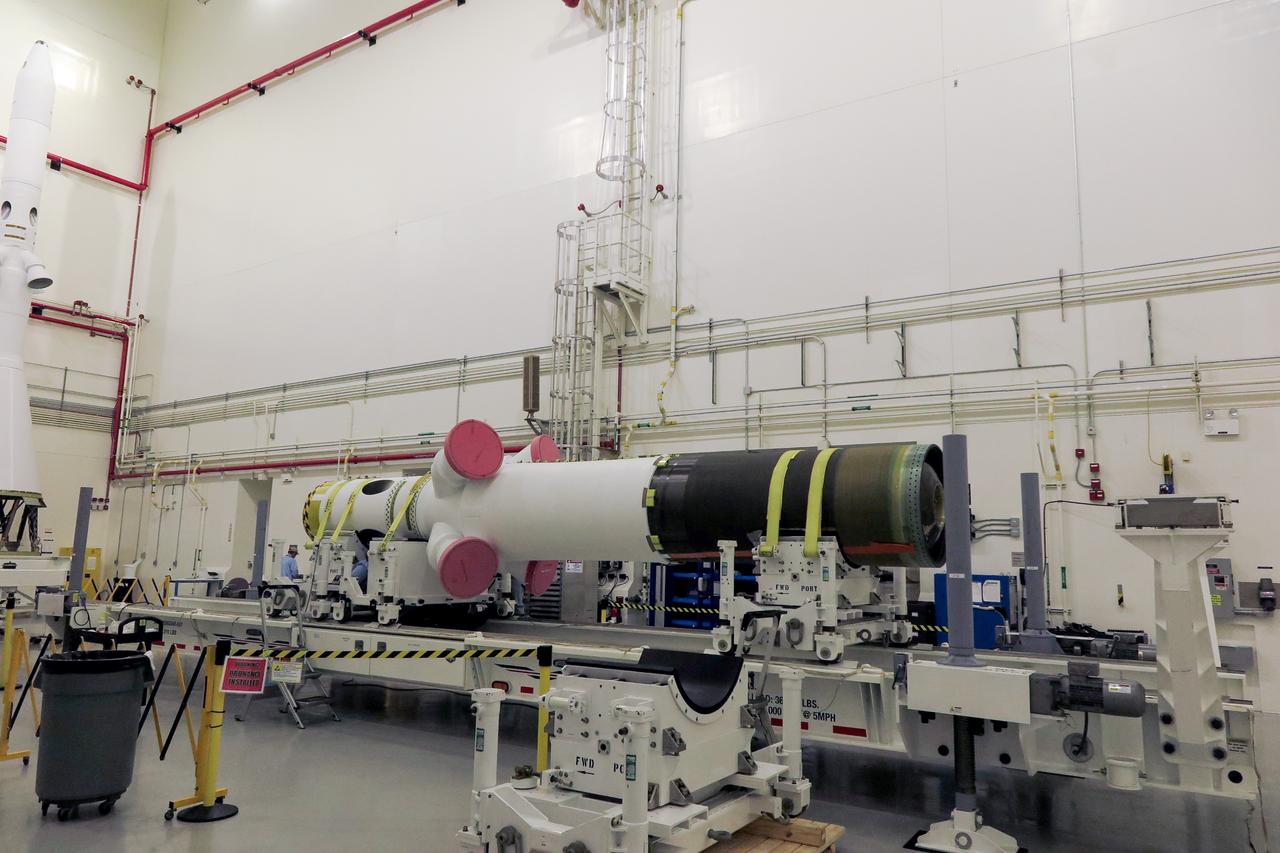
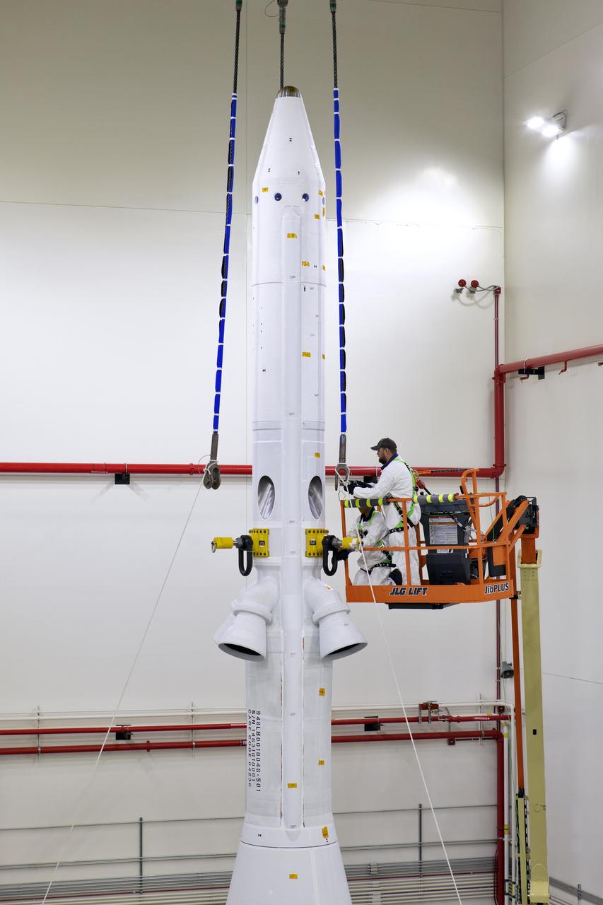
The jettison, abort, and attitude control motors for Artemis II are secured on a work stand inside the Launch Abort System Facility at NASA’s Kennedy Space Center in Florida on Nov. 17, 2021. The motors will continue undergoing inspections, testing, and assembly ahead of the first crewed Artemis mission. The launch abort system is designed to protect astronauts if a problem arises during launch by pulling the Orion spacecraft away from a failing rocket. Artemis II will confirm all the Orion spacecraft’s systems operate as designed in the actual environment of deep space with astronauts aboard.

The jettison, abort, and attitude control motors for Artemis II are secured on a work stand inside the Launch Abort System Facility at NASA’s Kennedy Space Center in Florida on Nov. 17, 2021. The motors will continue undergoing inspections, testing, and assembly ahead of the first crewed Artemis mission. The launch abort system is designed to protect astronauts if a problem arises during launch by pulling the Orion spacecraft away from a failing rocket. Artemis II will confirm all the Orion spacecraft’s systems operate as designed in the actual environment of deep space with astronauts aboard.
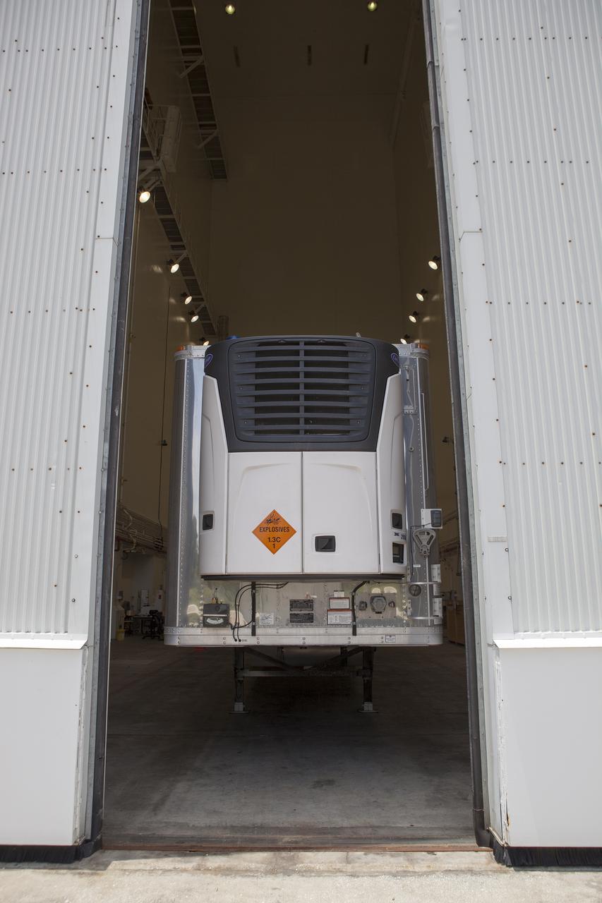
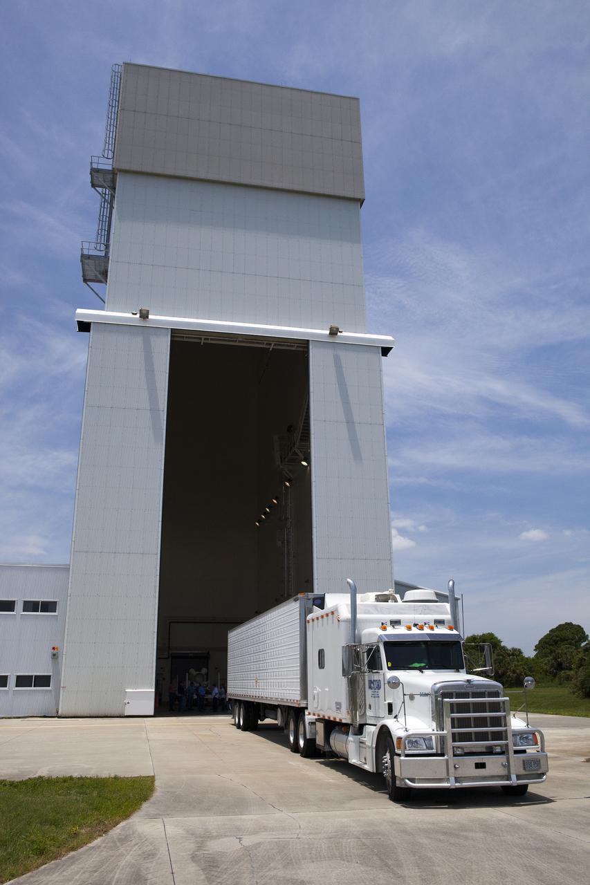
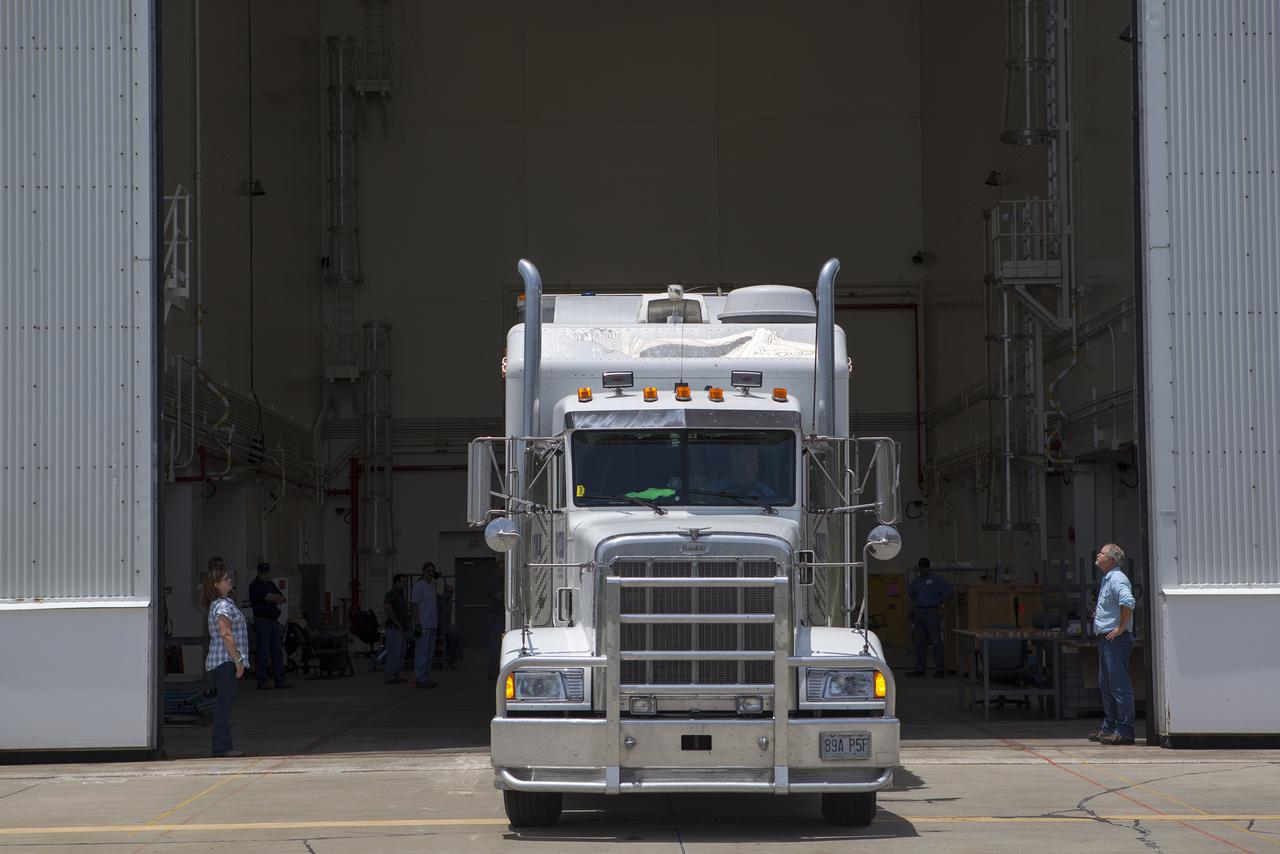
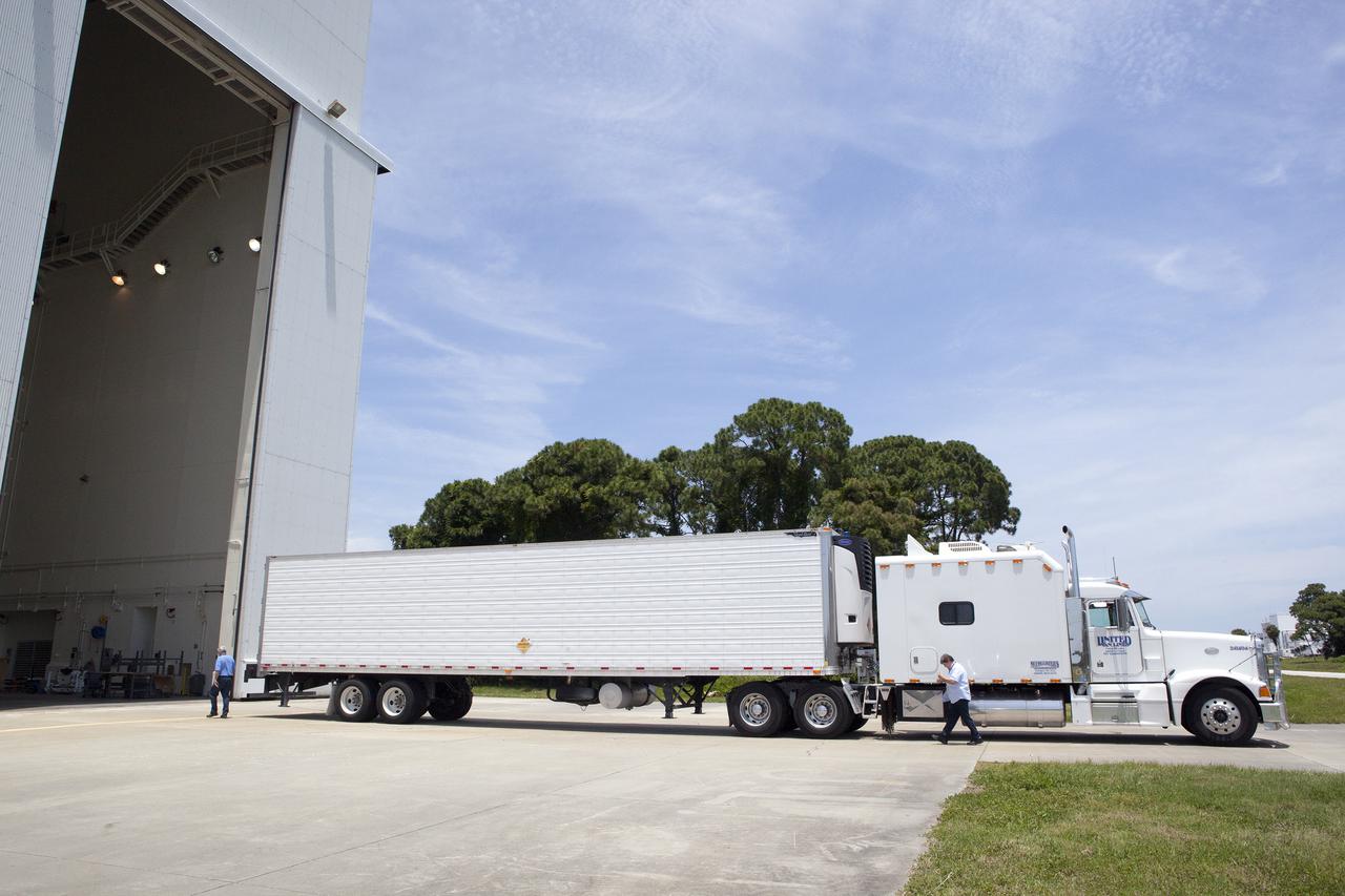
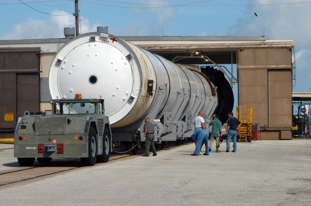
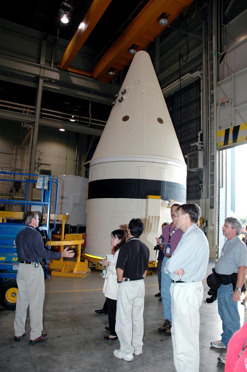
CAPE CANAVERAL, Fla. – At NASA’s Kennedy Space Center in Florida, a truck arrives at the Launch Abort System Facility with the jettison motor from Aerojet in Redmond, Wash. The motor is part of the Launch Abort System, or LAS, for Exploration Flight Test 1, or EFT-1, of the agency’s Orion Multi-Purpose Crew Vehicle. The motor will jettison the LAS away from the Orion crew capsule during the flight test’s early ascent phase. Orion’s Launch Abort System is designed to safely pull the Orion crew module away from the launch vehicle in the event of an emergency on the launch pad or during the initial ascent of NASA’s Space Launch System, or SLS, rocket. Orion is the exploration spacecraft designed to carry crews to space beyond low Earth orbit. It will provide emergency abort capability, sustain the crew during the space travel and provide safe re-entry from deep space return velocities. Orion’s first unpiloted test flight is scheduled to launch in 2014 atop a Delta IV rocket. A second uncrewed flight test is scheduled for 2017 on the SLS rocket. For more information, visit http:__www.nasa.gov_orion. Photo credit: NASA_Dimitri Gerondidakis
CAPE CANAVERAL, Fla. – At NASA’s Kennedy Space Center in Florida, a truck arrives at the Launch Abort System Facility with the jettison motor from Aerojet in Redmond, Wash. The motor is part of the Launch Abort System, or LAS, for Exploration Flight Test 1, or EFT-1, of the agency’s Orion Multi-Purpose Crew Vehicle. The motor will jettison the LAS away from the Orion crew capsule during the flight test’s early ascent phase. Orion’s Launch Abort System is designed to safely pull the Orion crew module away from the launch vehicle in the event of an emergency on the launch pad or during the initial ascent of NASA’s Space Launch System, or SLS, rocket. Orion is the exploration spacecraft designed to carry crews to space beyond low Earth orbit. It will provide emergency abort capability, sustain the crew during the space travel and provide safe re-entry from deep space return velocities. Orion’s first unpiloted test flight is scheduled to launch in 2014 atop a Delta IV rocket. A second uncrewed flight test is scheduled for 2017 on the SLS rocket. For more information, visit http:__www.nasa.gov_orion. Photo credit: NASA_Dimitri Gerondidakis
CAPE CANAVERAL, Fla. – At NASA’s Kennedy Space Center in Florida, a truck arrives at the Launch Abort System Facility with the jettison motor from Aerojet in Redmond, Wash. The motor is part of the Launch Abort System, or LAS, for Exploration Flight Test 1, or EFT-1, of the agency’s Orion Multi-Purpose Crew Vehicle. The motor will jettison the LAS away from the Orion crew capsule during the flight test’s early ascent phase. Orion’s Launch Abort System is designed to safely pull the Orion crew module away from the launch vehicle in the event of an emergency on the launch pad or during the initial ascent of NASA’s Space Launch System, or SLS, rocket. Orion is the exploration spacecraft designed to carry crews to space beyond low Earth orbit. It will provide emergency abort capability, sustain the crew during the space travel and provide safe re-entry from deep space return velocities. Orion’s first unpiloted test flight is scheduled to launch in 2014 atop a Delta IV rocket. A second uncrewed flight test is scheduled for 2017 on the SLS rocket. For more information, visit http:__www.nasa.gov_orion. Photo credit: NASA_Dimitri Gerondidakis
CAPE CANAVERAL, Fla. – At NASA’s Kennedy Space Center in Florida, a truck arrives at the Launch Abort System Facility with the jettison motor from Aerojet in Redmond, Wash. The motor is part of the Launch Abort System, or LAS, for Exploration Flight Test 1, or EFT-1, of the agency’s Orion Multi-Purpose Crew Vehicle. The motor will jettison the LAS away from the Orion crew capsule during the flight test’s early ascent phase. Orion’s Launch Abort System is designed to safely pull the Orion crew module away from the launch vehicle in the event of an emergency on the launch pad or during the initial ascent of NASA’s Space Launch System, or SLS, rocket. Orion is the exploration spacecraft designed to carry crews to space beyond low Earth orbit. It will provide emergency abort capability, sustain the crew during the space travel and provide safe re-entry from deep space return velocities. Orion’s first unpiloted test flight is scheduled to launch in 2014 atop a Delta IV rocket. A second uncrewed flight test is scheduled for 2017 on the SLS rocket. For more information, visit http:__www.nasa.gov_orion. Photo credit: NASA_Dimitri Gerondidakis
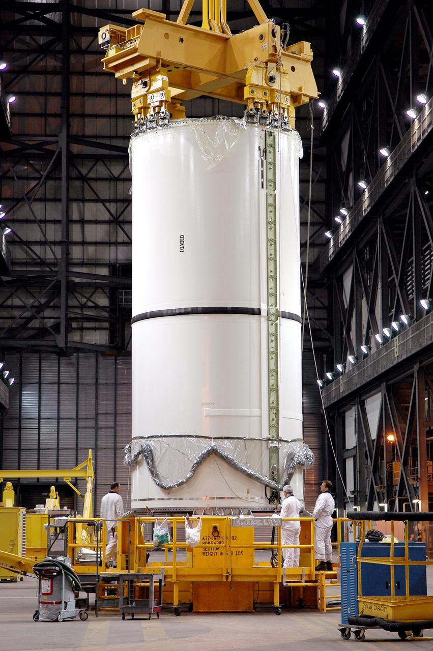
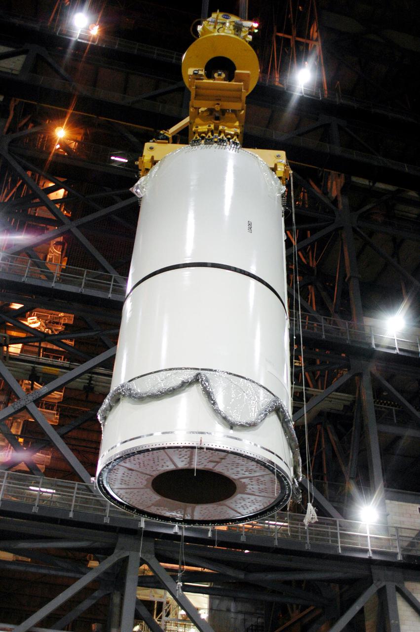
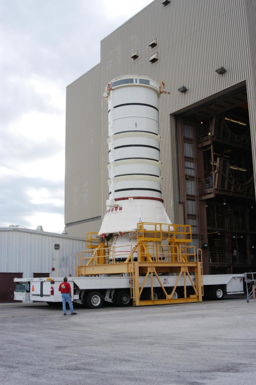
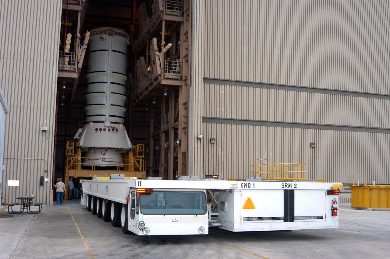
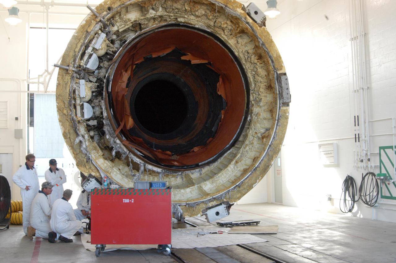
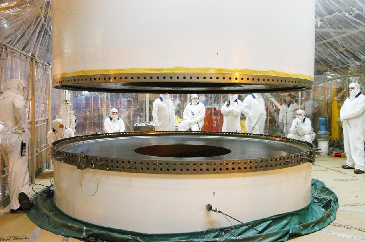
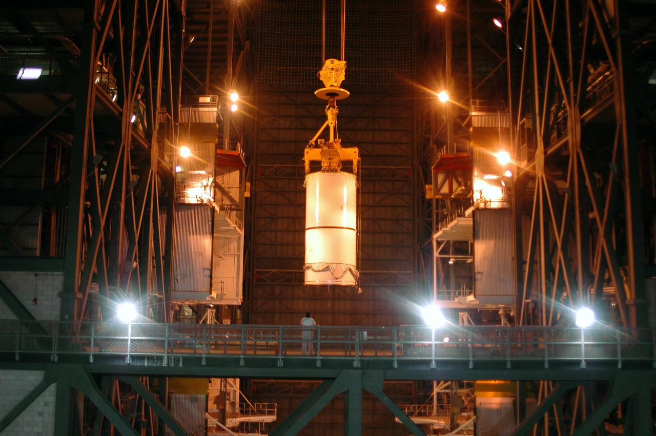
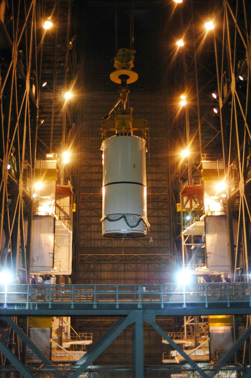
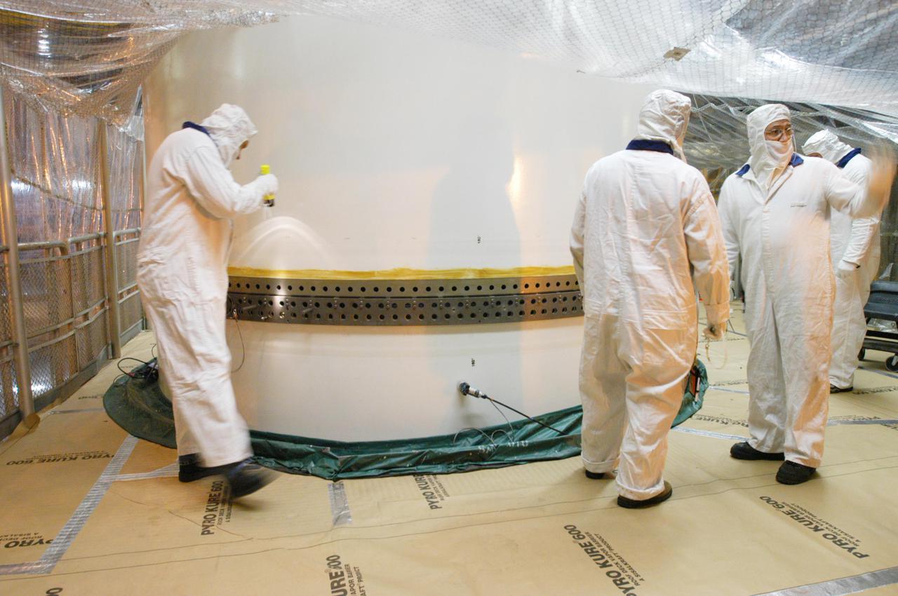
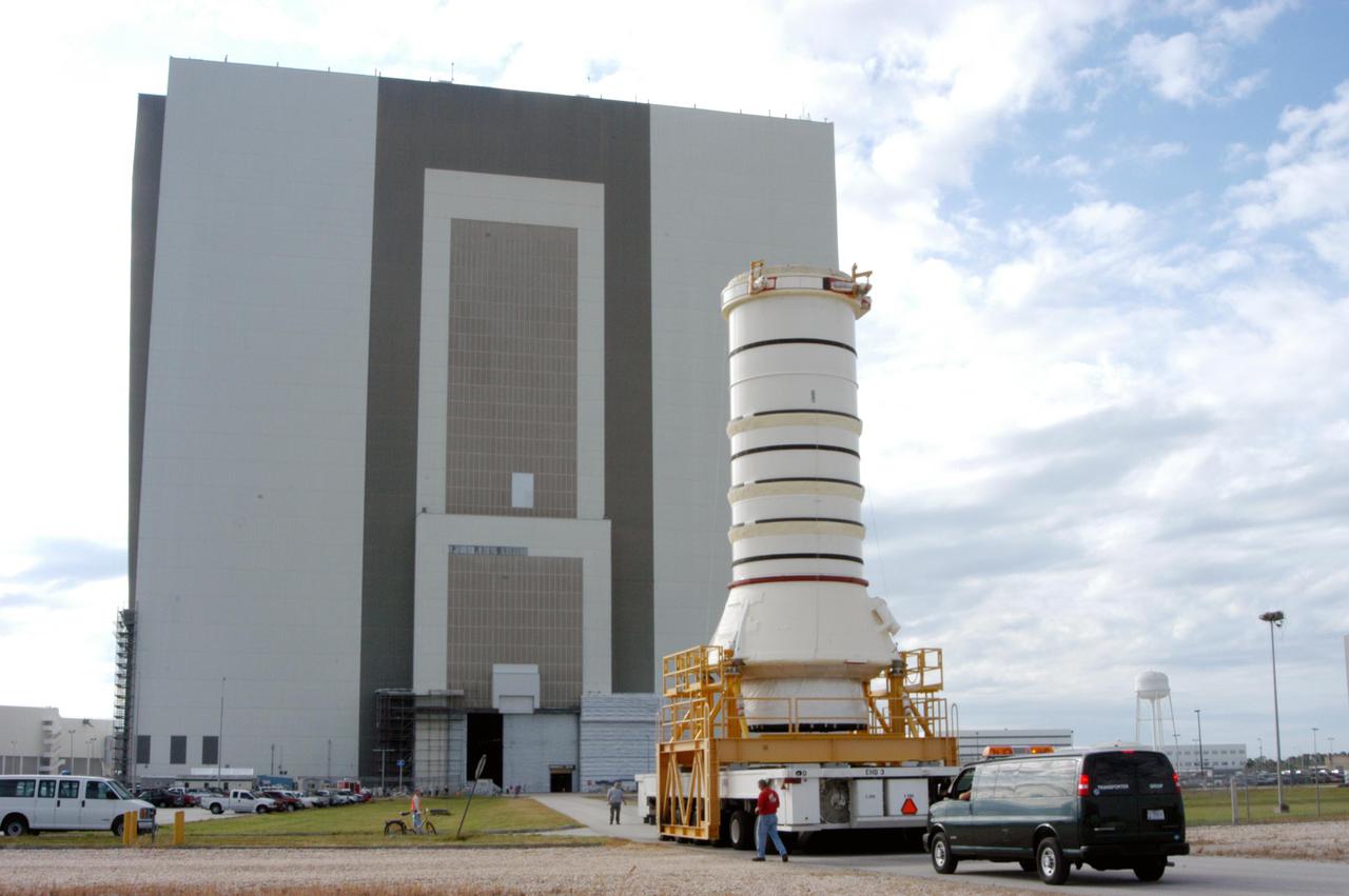
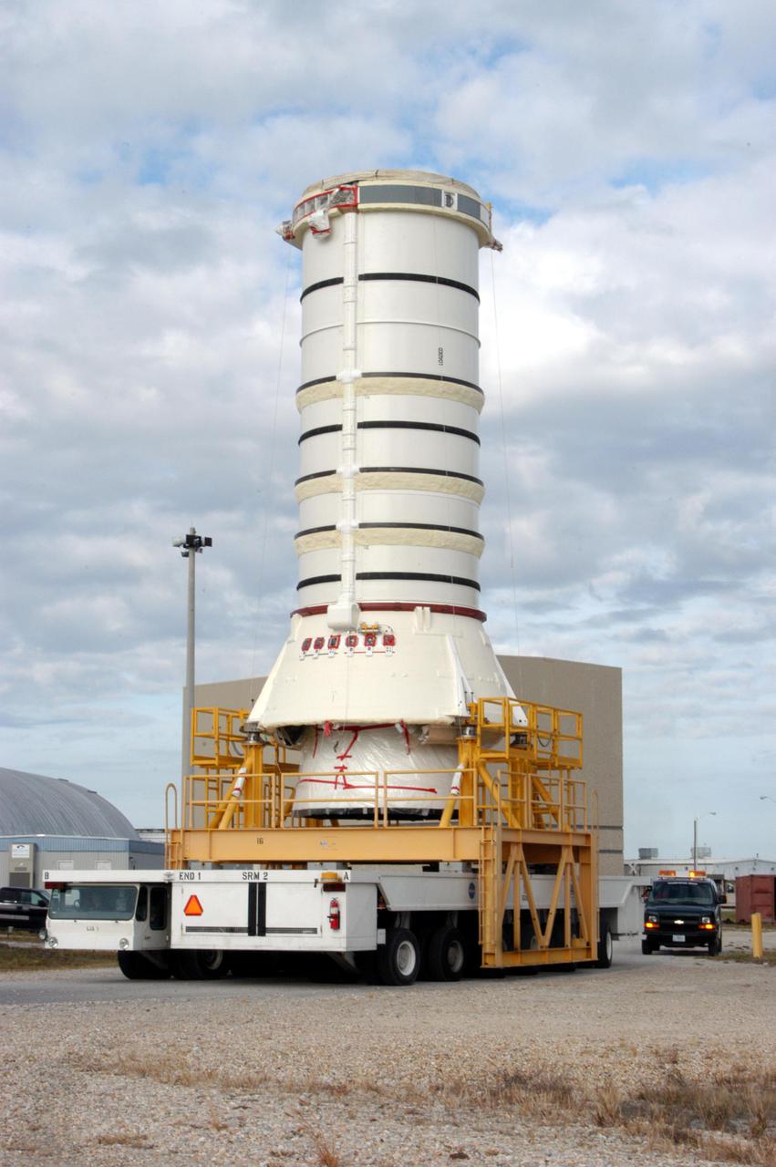
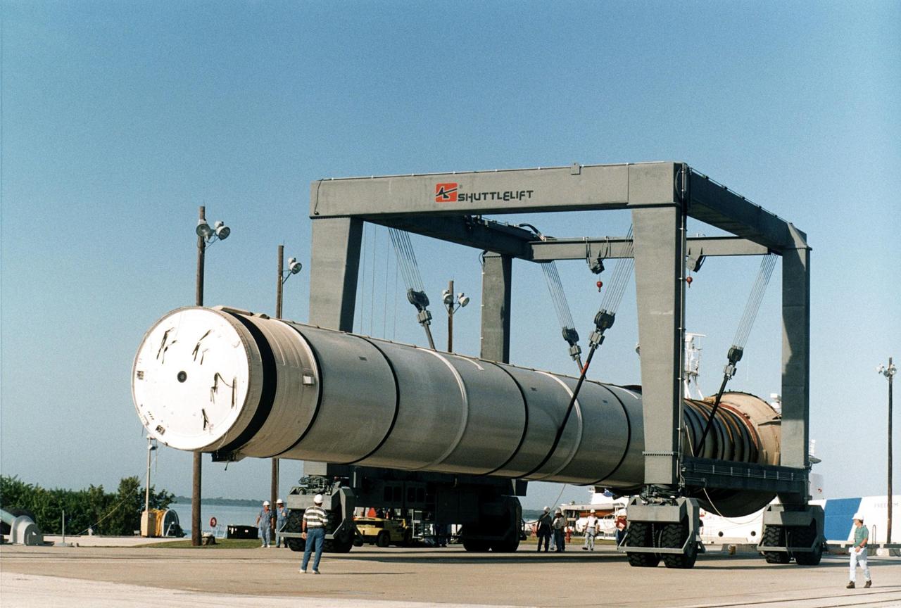
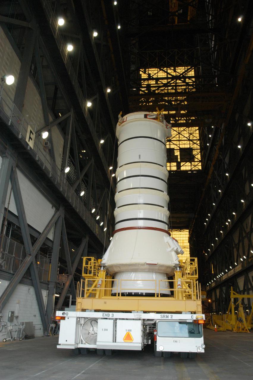
KENNEDY SPACE CENTER, FLA. - Inside the Vehicle Assembly Building (VAB), a segment of a Solid Rocket Booster (SRB) is prepared for lifting. This right aft center segment will be stacked with the aft booster that arrived in the VAB Nov. 22 for the Return to Flight mission STS-114. Two SRBs are stacked on the Mobile Launch Platform and later joined by the External Tank.. The twin 149-foot tall, 12-foot diameter SRBs provide the main propulsion system during launch. They operate parallel with the Space Shuttle main engines for the first two minutes of flight and jettison away from the orbiter with help from the Booster Separation Motors, about 26.3 nautical miles above the Earth’s surface.
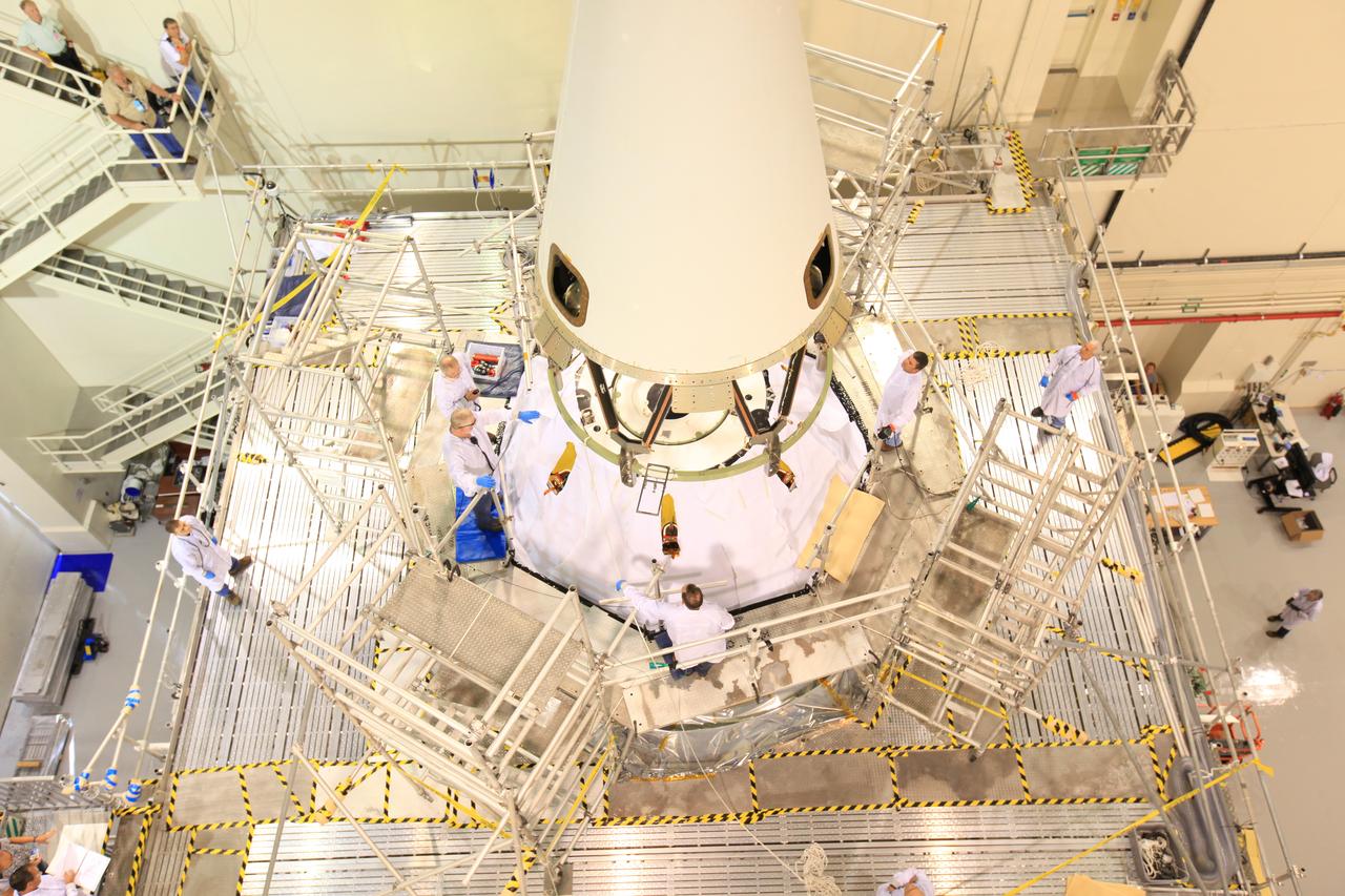
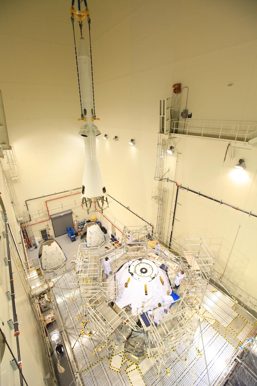
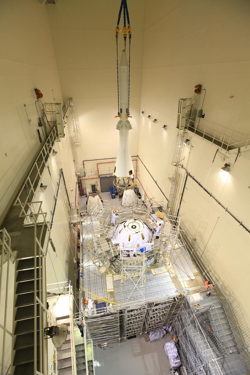
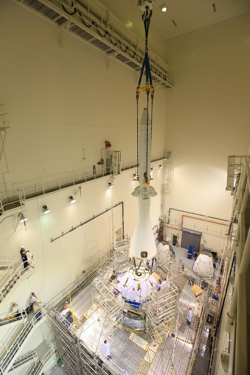
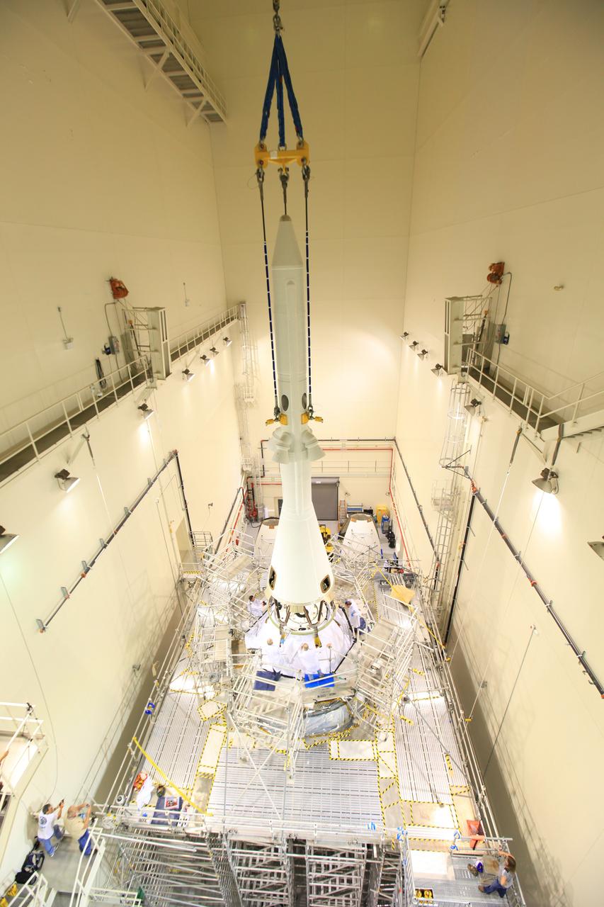
Exploration Flight Test-1 (EFT-1) Orion's launch abort system, or LAS, is positioned atop the crew and service module in the Launch Abort System Facility (LASF) at Kennedy Space Center on Oct. 3, 2014, in preparation for rollout to mate with the Delta IV Heavy launch vehicle. The LAS is designed to activate within milliseconds to pull the crew module to safety in case of an emergency. Exploration Flight Test-1 (EFT-1) verified the function of the jettison motor to separate the LAS from the crew module to ensure a safe, successful mission. Part of Batch image transfer from Flickr.
Exploration Flight Test-1 (EFT-1) Orion's launch abort system, or LAS, is positioned atop the crew and service module in the Launch Abort System Facility (LASF) at Kennedy Space Center on Oct. 3, 2014, in preparation for rollout to mate with the Delta IV Heavy launch vehicle. The LAS is designed to activate within milliseconds to pull the crew module to safety in case of an emergency. Exploration Flight Test-1 (EFT-1) verified the function of the jettison motor to separate the LAS from the crew module to ensure a safe, successful mission. Part of Batch image transfer from Flickr.
Exploration Flight Test-1 (EFT-1) Orion's launch abort system, or LAS, is positioned atop the crew and service module in the Launch Abort System Facility (LASF) at Kennedy Space Center on Oct. 3, 2014, in preparation for rollout to mate with the Delta IV Heavy launch vehicle. The LAS is designed to activate within milliseconds to pull the crew module to safety in case of an emergency. Exploration Flight Test-1 (EFT-1) verified the function of the jettison motor to separate the LAS from the crew module to ensure a safe, successful mission. Part of Batch image transfer from Flickr.
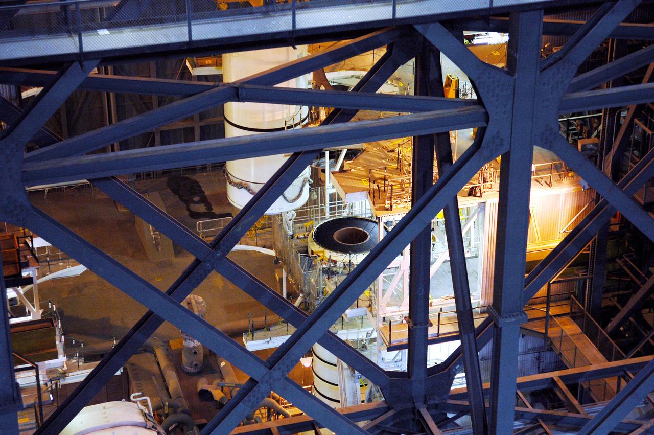
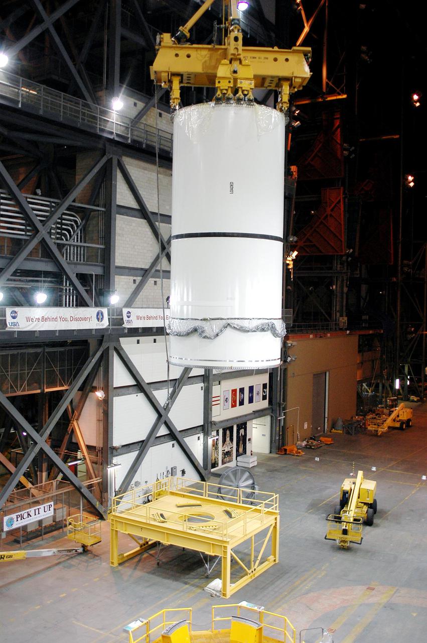
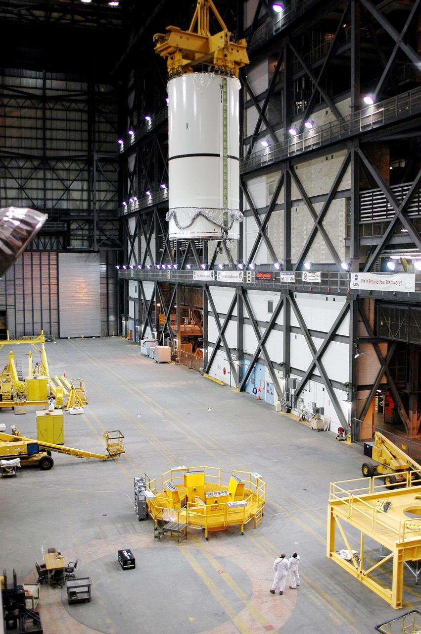
KENNEDY SPACE CENTER, FLA. - In the Vehicle Assembly Building (VAB), a segment of a Solid Rocket Booster (SRB) is lifted to the 16th level. This right aft center segment will be stacked with the aft booster that arrived in the VAB Nov. 22 for the Return to Flight mission STS-114. Two SRBs are stacked on the Mobile Launch Platform and later joined by the External Tank. The twin 149-foot tall, 12-foot diameter SRBs provide the main propulsion system during launch. They operate parallel with the Space Shuttle main engines for the first two minutes of flight and jettison away from the orbiter with help from the Booster Separation Motors, about 26.3 nautical miles above the Earth’s surface.
Exploration Flight Test-1 (EFT-1) Orion's launch abort system, or LAS, is positioned atop the crew and service module in the Launch Abort System Facility (LASF) at Kennedy Space Center on Oct. 3, 2014, in preparation for rollout to mate with the Delta IV Heavy launch vehicle. The LAS is designed to activate within milliseconds to pull the crew module to safety in case of an emergency. Exploration Flight Test-1 (EFT-1) verified the function of the jettison motor to separate the LAS from the crew module to ensure a safe, successful mission. Part of Batch image transfer from Flickr.
Exploration Flight Test-1 (EFT-1) Orion's launch abort system, or LAS, is positioned atop the crew and service module in the Launch Abort System Facility (LASF) at Kennedy Space Center on Oct. 3, 2014, in preparation for rollout to mate with the Delta IV Heavy launch vehicle. The LAS is designed to activate within milliseconds to pull the crew module to safety in case of an emergency. Exploration Flight Test-1 (EFT-1) verified the function of the jettison motor to separate the LAS from the crew module to ensure a safe, successful mission. Part of Batch image transfer from Flickr.
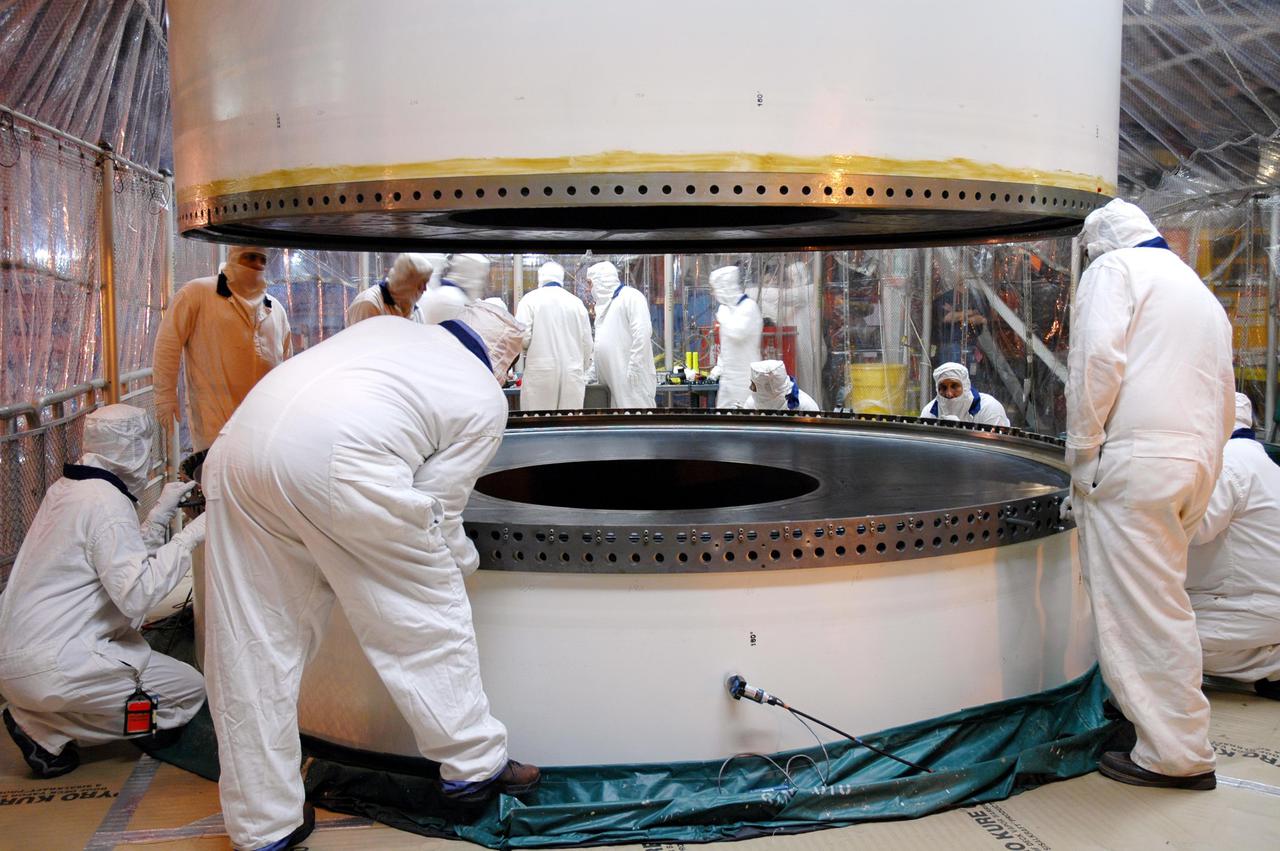
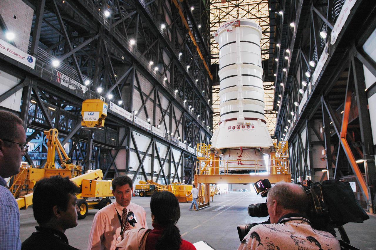
KENNEDY SPACE CENTER, FLA. - In the Vehicle Assembly Building (VAB), the right aft center segment of a Solid Rocket Booster (SRB) is lowered toward the aft booster for mating. The aft booster arrived in the VAB Nov. 22 for the Return to Flight mission STS-114. Two SRBs are stacked on the Mobile Launch Platform and later joined by the External Tank.. The twin 149-foot tall, 12-foot diameter SRBs provide the main propulsion system during launch. They operate parallel with the Space Shuttle main engines for the first two minutes of flight and jettison away from the orbiter with help from the Booster Separation Motors, about 26.3 nautical miles above the Earth’s surface.
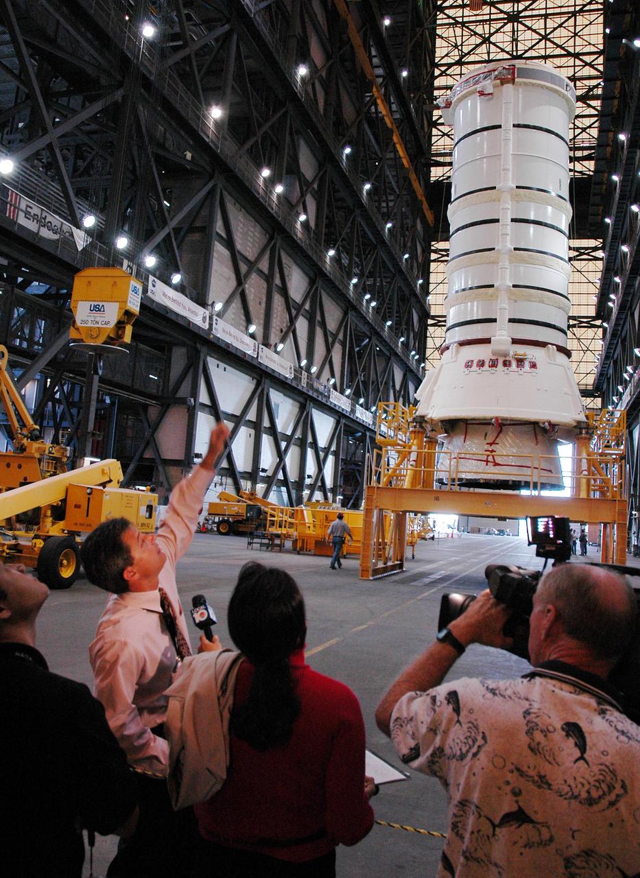
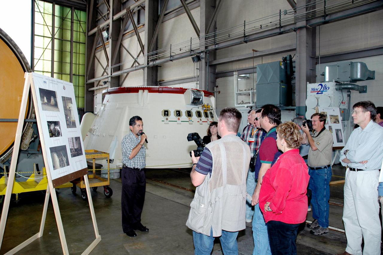
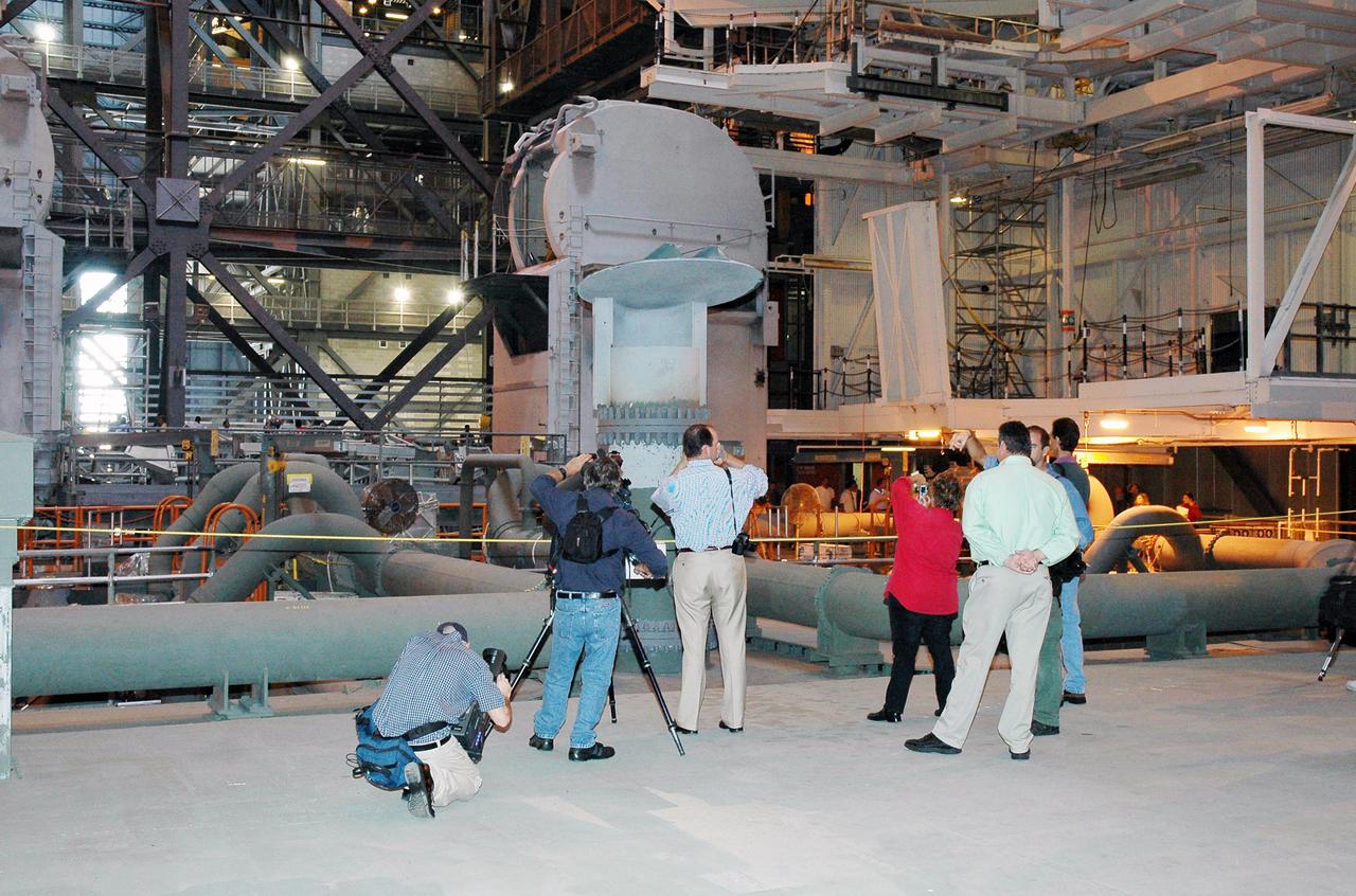
KENNEDY SPACE CENTER, FLA. - Inside the Vehicle Assembly Building, media are shown where the aft skirt and lower segment of the Solid Rocket Booster for the Return to Flight mission STS-114 will be stacked with other segments to follow. Two SRBs support the liftoff of the Space Shuttle on a launch. The twin 149-foot tall, 12-foot diameter SRBs provide the main propulsion system during launch to place the 180,000-pound orbiters in the proper orbit around the Earth. They operate parallel with the Space Shuttle main engines for the first two minutes of flight and jettison away from the orbiter with help from the Booster Separation Motors, about 26.3 nautical miles above the Earth’s surface.
CAPE CANAVERAL, Fla. – Inside the Launch Abort System Facility at NASA’s Kennedy Space Center in Florida, a technician works on the launch abort system, or LAS, for the Orion Exploration Flight Test-1 mission. Horizontally stacked together are the components of the LAS, the launch abort motor, the attitude control motor, the jettison motor and the fairing. Orion is the exploration spacecraft designed to carry crews to space beyond low Earth orbit. It will provide emergency abort capability, sustain the crew during the space travel and provide safe re-entry from deep space return velocities. The LAS is designed to safely pull the Orion crew module away from the launch vehicle in the event of an emergency on the launch pad or during the initial ascent of NASA’s Space Launch System, or SLS, rocket. Orion’s first unpiloted test flight is scheduled to launch in 2014 atop a Delta IV rocket. A second uncrewed flight test is scheduled for 2017 on the SLS rocket. For more information, visit http://www.nasa.gov/orion. Photo credit: NASA/Jim Grossmann
CAPE CANAVERAL, Fla. – Inside the Launch Abort System Facility at NASA’s Kennedy Space Center in Florida, the launch abort system, or LAS, components are horizontally stacked as processing continues for the Orion Exploration Flight Test-1 mission. Components of the LAS are the launch abort motor, the attitude control motor, the jettison motor and the fairing. Orion is the exploration spacecraft designed to carry crews to space beyond low Earth orbit. It will provide emergency abort capability, sustain the crew during the space travel and provide safe re-entry from deep space return velocities. The LAS is designed to safely pull the Orion crew module away from the launch vehicle in the event of an emergency on the launch pad or during the initial ascent of NASA’s Space Launch System, or SLS, rocket. Orion’s first unpiloted test flight is scheduled to launch in 2014 atop a Delta IV rocket. A second uncrewed flight test is scheduled for 2017 on the SLS rocket. For more information, visit http://www.nasa.gov/orion. Photo credit: NASA/Jim Grossmann
Inside the Launch Abort System Facility (LASF) at NASA’s Kennedy Space Center in Florida, workers are completing the integration of a test version of the Orion crew module with the Launch Abort System (LAS) on May 18, 2019. In view are the LAS attitude control motor, jettison motor and abort motor. The test vehicle and the LAS will be used for the Orion Ascent Abort-2 (AA-2) Flight Test. AA-2 is a full-stress test of the LAS, planned for July 2. AA-2 will launch from Space Launch Complex 46, carrying a fully functional LAS and a 22,000-pound Orion test vehicle to an altitude of 31,000 feet and traveling at more than 1,000 miles an hour. The test will verify the LAS can steer the crew module and astronauts aboard to safety if an emergency occurs during ascent on the Space Launch System (SLS) rocket. NASA's Orion and Exploration Ground Systems programs, contractors Jacob's, Lockheed Martin and Northrop Grumman, in conjunction with the Air Force Space and Missile Center's Launch Operations branch and the 45th Space Wing are performing flight operations for AA-2.
CAPE CANAVERAL, Fla. – Inside the Launch Abort System Facility at NASA’s Kennedy Space Center in Florida, technicians prepare to work on the launch abort system, or LAS, for the Orion Exploration Flight Test-1 mission. Horizontally stacked together are the components of the LAS, the launch abort motor, the attitude control motor, the jettison motor and the fairing. Orion is the exploration spacecraft designed to carry crews to space beyond low Earth orbit. It will provide emergency abort capability, sustain the crew during the space travel and provide safe re-entry from deep space return velocities. The LAS is designed to safely pull the Orion crew module away from the launch vehicle in the event of an emergency on the launch pad or during the initial ascent of NASA’s Space Launch System, or SLS, rocket. Orion’s first unpiloted test flight is scheduled to launch in 2014 atop a Delta IV rocket. A second uncrewed flight test is scheduled for 2017 on the SLS rocket. For more information, visit http://www.nasa.gov/orion. Photo credit: NASA/Jim Grossmann
CAPE CANAVERAL, Fla. – Inside the Launch Abort System Facility at NASA’s Kennedy Space Center in Florida, the launch abort system, or LAS, components are horizontally stacked as processing continues for the Orion Exploration Flight Test-1 mission. Components of the LAS are the launch abort motor, the attitude control motor, the jettison motor and the fairing. Orion is the exploration spacecraft designed to carry crews to space beyond low Earth orbit. It will provide emergency abort capability, sustain the crew during the space travel and provide safe re-entry from deep space return velocities. The LAS is designed to safely pull the Orion crew module away from the launch vehicle in the event of an emergency on the launch pad or during the initial ascent of NASA’s Space Launch System, or SLS, rocket. Orion’s first unpiloted test flight is scheduled to launch in 2014 atop a Delta IV rocket. A second uncrewed flight test is scheduled for 2017 on the SLS rocket. For more information, visit http://www.nasa.gov/orion. Photo credit: NASA/Jim Grossmann
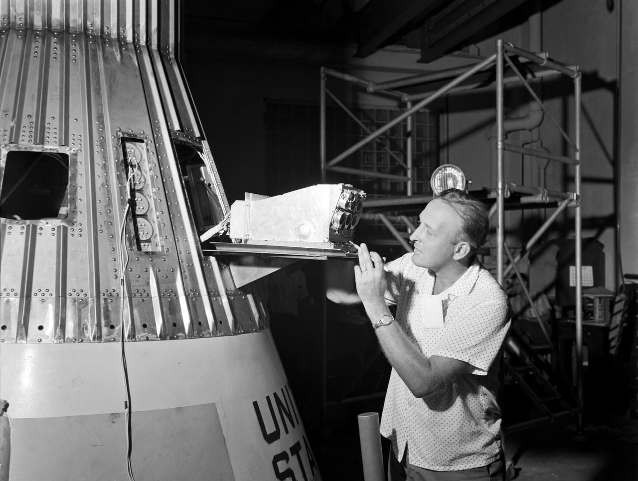
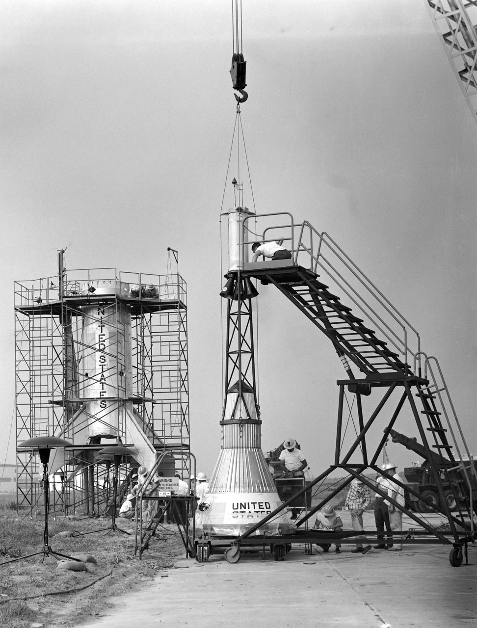
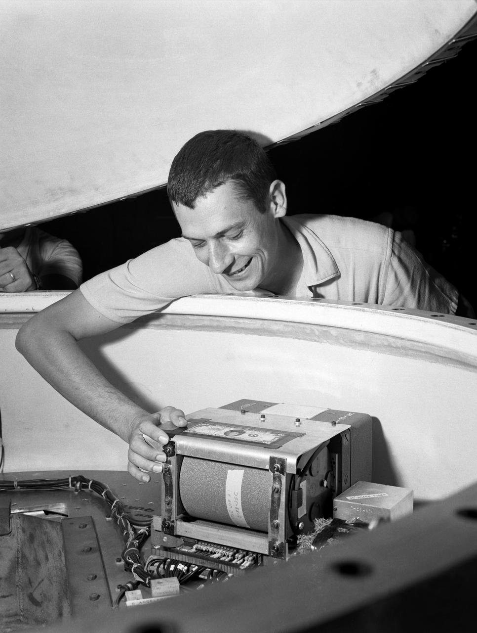
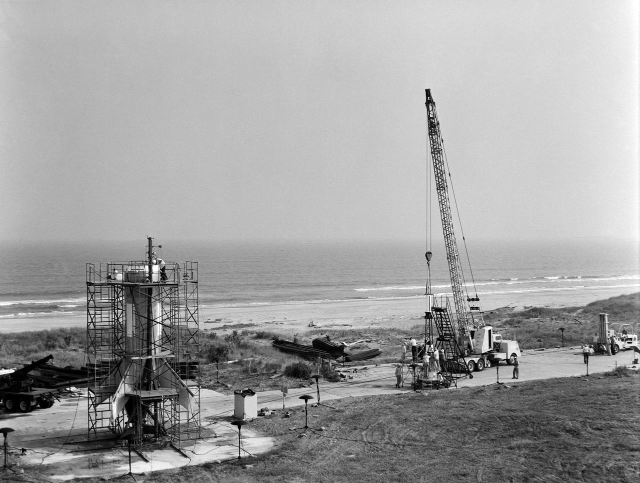
Technicians adjust the rocket motor during the attachment of the escape tower to the Mercury capsule prior to assembly with Little Joe launcher, August 20, 1959. Joseph Shortal wrote (vol. 3., p. 33): The escape tower and rocket motors were taken from the Mercury capsule production. The tower is shown being attached to the capsule.... The escape rocket was a Grand Central 1-KS-52000 motor with three canted nozzles. The tower-jettison motor was an Atlantic Research Corp. 1.4-KS-785 motor. This was the same design tested in a beach abort test...and had the offset thrust line as used in the beach abort test to insure that the capsule would get away from the booster in an emergency. The escape system weighed 1,015 pounds, including 236 pounds of ballast for stability. The Little Joe booster was assembled at Wallops on its special launcher in a vertical attitude. It is shown in the on the left with the work platform in place. The launcher was located on a special concrete slab in Launching Area 1. The capsule was lowered onto the booster by crane.... After the assembly was completed, the scaffolding was disassembled and the launcher pitched over to its normal launch angle of 80 degrees.... Little Joe had a diameter of 80 inches and an overall length, including the capsule and escape tower of 48 feet. The total weight at launch was about 43,000 pounds. The overall span of the stabilizing fins was 21.3 feet. Although in comparison with the overall Mercury Project, Little Joe was a simple undertaking, the fact that an attempt was made to condense a normal two-year project into a 6-month one with in house labor turned it into a major undertaking for Langley. -- Published in Joseph A. Shortal, History of Wallops Station: Origins and Activities Through 1949, (Wallops Island, VA: National Aeronautics and Space Administration, Wallops Station, nd), Comment Edition.
Technicians adjust the rocket motor during the attachment of the escape tower to the Mercury capsule prior to assembly with Little Joe launcher, August 20, 1959. Joseph Shortal wrote (vol. 3., p. 33): The escape tower and rocket motors were taken from the Mercury capsule production. The tower is shown being attached to the capsule.... The escape rocket was a Grand Central 1-KS-52000 motor with three canted nozzles. The tower-jettison motor was an Atlantic Research Corp. 1.4-KS-785 motor. This was the same design tested in a beach abort test...and had the offset thrust line as used in the beach abort test to insure that the capsule would get away from the booster in an emergency. The escape system weighed 1,015 pounds, including 236 pounds of ballast for stability. The Little Joe booster was assembled at Wallops on its special launcher in a vertical attitude. It is shown in the on the left with the work platform in place. The launcher was located on a special concrete slab in Launching Area 1. The capsule was lowered onto the booster by crane.... After the assembly was completed, the scaffolding was disassembled and the launcher pitched over to its normal launch angle of 80 degrees.... Little Joe had a diameter of 80 inches and an overall length, including the capsule and escape tower of 48 feet. The total weight at launch was about 43,000 pounds. The overall span of the stabilizing fins was 21.3 feet. Although in comparison with the overall Mercury Project, Little Joe was a simple undertaking, the fact that an attempt was made to condense a normal two-year project into a 6-month one with in house labor turned it into a major undertaking for Langley. -- Published in Joseph A. Shortal, History of Wallops Station: Origins and Activities Through 1949, (Wallops Island, VA: National Aeronautics and Space Administration, Wallops Station, nd), Comment Edition.
Technicians adjust the rocket motor during the attachment of the escape tower to the Mercury capsule prior to assembly with Little Joe launcher, August 20, 1959. Joseph Shortal wrote (vol. 3., p. 33): The escape tower and rocket motors were taken from the Mercury capsule production. The tower is shown being attached to the capsule.... The escape rocket was a Grand Central 1-KS-52000 motor with three canted nozzles. The tower-jettison motor was an Atlantic Research Corp. 1.4-KS-785 motor. This was the same design tested in a beach abort test...and had the offset thrust line as used in the beach abort test to insure that the capsule would get away from the booster in an emergency. The escape system weighed 1,015 pounds, including 236 pounds of ballast for stability. The Little Joe booster was assembled at Wallops on its special launcher in a vertical attitude. It is shown in the on the left with the work platform in place. The launcher was located on a special concrete slab in Launching Area 1. The capsule was lowered onto the booster by crane.... After the assembly was completed, the scaffolding was disassembled and the launcher pitched over to its normal launch angle of 80 degrees.... Little Joe had a diameter of 80 inches and an overall length, including the capsule and escape tower of 48 feet. The total weight at launch was about 43,000 pounds. The overall span of the stabilizing fins was 21.3 feet. Although in comparison with the overall Mercury Project, Little Joe was a simple undertaking, the fact that an attempt was made to condense a normal two-year project into a 6-month one with in house labor turned it into a major undertaking for Langley. -- Published in Joseph A. Shortal, History of Wallops Station: Origins and Activities Through 1949, (Wallops Island, VA: National Aeronautics and Space Administration, Wallops Station, nd), Comment Edition.

Technicians adjust the rocket motor during the attachment of the escape tower to the Mercury capsule prior to assembly with Little Joe launcher, August 20, 1959. Joseph Shortal wrote (vol. 3., p. 33): The escape tower and rocket motors were taken from the Mercury capsule production. The tower is shown being attached to the capsule.... The escape rocket was a Grand Central 1-KS-52000 motor with three canted nozzles. The tower-jettison motor was an Atlantic Research Corp. 1.4-KS-785 motor. This was the same design tested in a beach abort test...and had the offset thrust line as used in the beach abort test to insure that the capsule would get away from the booster in an emergency. The escape system weighed 1,015 pounds, including 236 pounds of ballast for stability. The Little Joe booster was assembled at Wallops on its special launcher in a vertical attitude. It is shown in the on the left with the work platform in place. The launcher was located on a special concrete slab in Launching Area 1. The capsule was lowered onto the booster by crane.... After the assembly was completed, the scaffolding was disassembled and the launcher pitched over to its normal launch angle of 80 degrees.... Little Joe had a diameter of 80 inches and an overall length, including the capsule and escape tower of 48 feet. The total weight at launch was about 43,000 pounds. The overall span of the stabilizing fins was 21.3 feet. Although in comparison with the overall Mercury Project, Little Joe was a simple undertaking, the fact that an attempt was made to condense a normal two-year project into a 6-month one with in house labor turned it into a major undertaking for Langley. -- Published in Joseph A. Shortal, History of Wallops Station: Origins and Activities Through 1949, (Wallops Island, VA: National Aeronautics and Space Administration, Wallops Station, nd), Comment Edition.
Technicians adjust the rocket motor during the attachment of the escape tower to the Mercury capsule prior to assembly with Little Joe launcher, August 20, 1959. Joseph Shortal wrote (vol. 3., p. 33): The escape tower and rocket motors were taken from the Mercury capsule production. The tower is shown being attached to the capsule.... The escape rocket was a Grand Central 1-KS-52000 motor with three canted nozzles. The tower-jettison motor was an Atlantic Research Corp. 1.4-KS-785 motor. This was the same design tested in a beach abort test...and had the offset thrust line as used in the beach abort test to insure that the capsule would get away from the booster in an emergency. The escape system weighed 1,015 pounds, including 236 pounds of ballast for stability. The Little Joe booster was assembled at Wallops on its special launcher in a vertical attitude. It is shown in the on the left with the work platform in place. The launcher was located on a special concrete slab in Launching Area 1. The capsule was lowered onto the booster by crane.... After the assembly was completed, the scaffolding was disassembled and the launcher pitched over to its normal launch angle of 80 degrees.... Little Joe had a diameter of 80 inches and an overall length, including the capsule and escape tower of 48 feet. The total weight at launch was about 43,000 pounds. The overall span of the stabilizing fins was 21.3 feet. Although in comparison with the overall Mercury Project, Little Joe was a simple undertaking, the fact that an attempt was made to condense a normal two-year project into a 6-month one with in house labor turned it into a major undertaking for Langley. -- Published in Joseph A. Shortal, History of Wallops Station: Origins and Activities Through 1949, (Wallops Island, VA: National Aeronautics and Space Administration, Wallops Station, nd), Comment Edition.
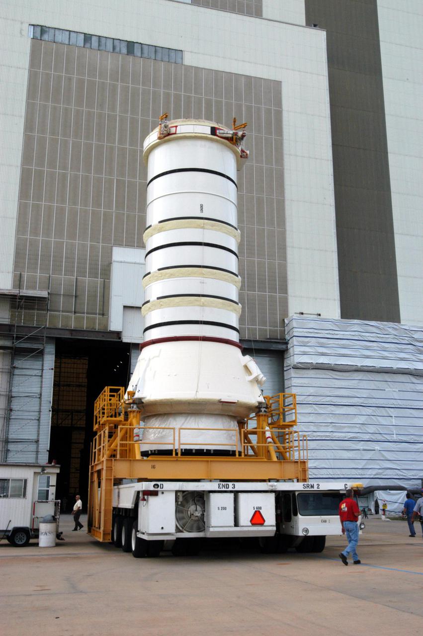
KENNEDY SPACE CENTER, FLA. - The aft skirt and lower segment of the Solid Rocket Booster (SRB) being prepared for Return to Flight on mission STS-114 leave the Rotation Processing and Surge Facility. The segments are being transported to the Vehicle Assembly Building where they will be prepared for stacking with the other segments arriving later. Two SRBs support the liftoff of the Space Shuttle on a launch. The twin 149-foot tall, 12-foot diameter SRBs provide the main propulsion system during launch to place the 180,000-pound orbiters in the proper orbit around the Earth. They operate parallel with the Space Shuttle main engines for the first two minutes of flight and jettison away from the orbiter with help from the Booster Separation Motors, about 26.3 nautical miles above the Earth’s surface.
KENNEDY SPACE CENTER, FLA. - In a Vehicle Assembly Building (VAB) high bay, an aft center segment of a Solid Rocket Booster (SRB) is lowered toward an aft segment already secured to a Mobile Launch Platform. These segments are part of the right SRB for the Space Shuttle Return to Flight mission, STS-114. Two SRBs are stacked on a Mobile Launch Platform for each Shuttle flight and later joined by an External Tank. The twin 149-foot tall, 12-foot diameter SRBs provide the main propulsion system during launch. They operate in parallel with the Space Shuttle main engines for the first two minutes of flight and jettison away from the orbiter with help from the Booster Separation Motors, about 26.3 nautical miles above the Earth’s surface.
KENNEDY SPACE CENTER, FLA. - The transporter arrives at the Rotation Processing and Surge Facility to move the aft skirt and lower segment of the Solid Rocket Booster (SRB) to the Vehicle Assembly. These segments are the first to be prepared for Return to Flight on mission STS-114. Other segments will follow for stacking. Two SRBs support the liftoff of the Space Shuttle on a launch. The twin 149-foot tall, 12-foot diameter SRBs provide the main propulsion system during launch to place the 180,000-pound orbiters in the proper orbit around the Earth. They operate parallel with the Space Shuttle main engines for the first two minutes of flight and jettison away from the orbiter with help from the Booster Separation Motors, about 26.3 nautical miles above the Earth’s surface.
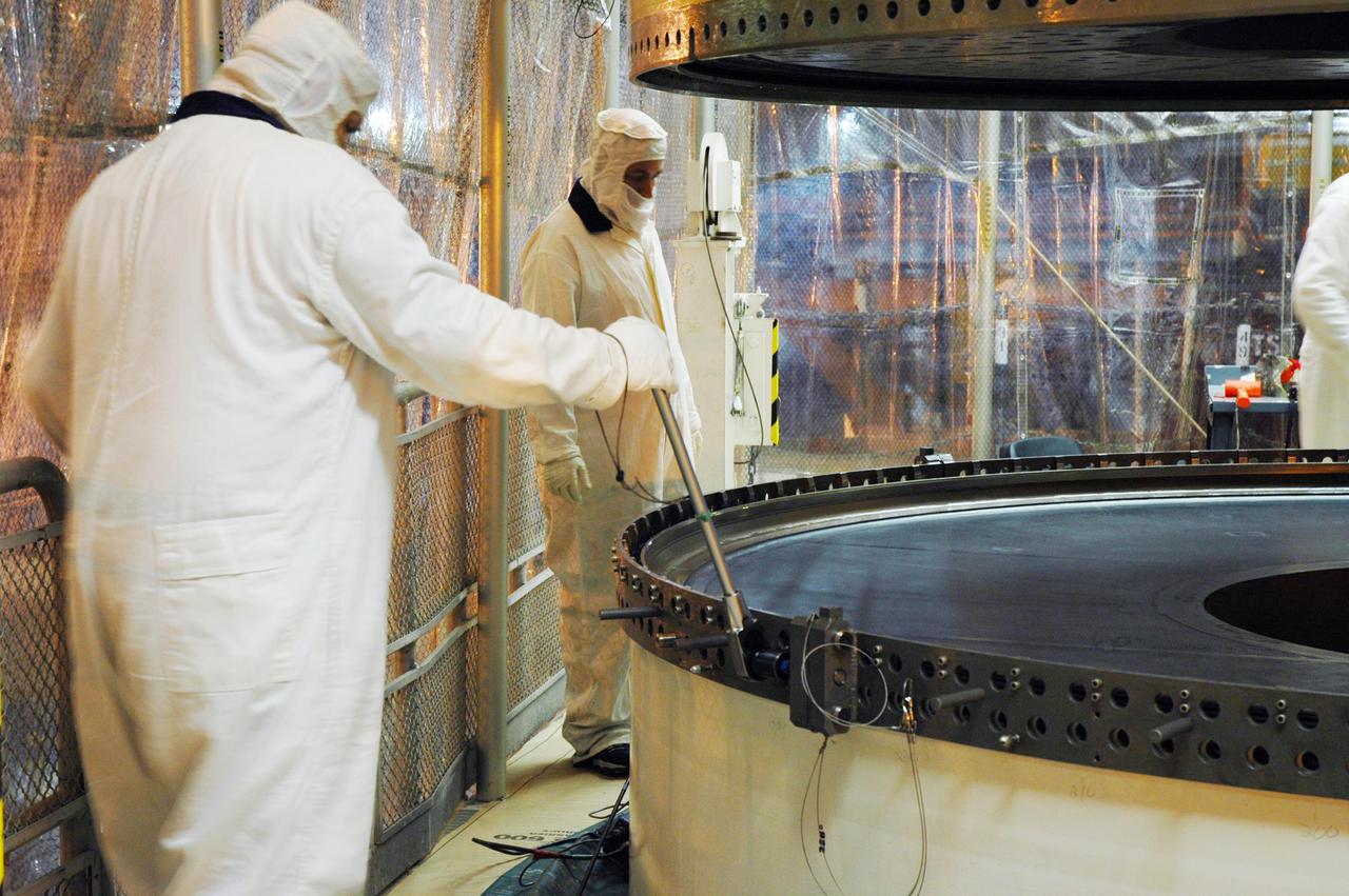
KENNEDY SPACE CENTER, FLA. - One of the spent Solid Rocket Boosters (SRBs) from the launch of Space Shuttle Discovery July 26 on Return to Flight mission STS-114 is moved into Hangar AF at Cape Canaveral Air Force Station. The SRBs are the largest solid propellant motors ever flown and the first designed for reuse. After a Shuttle is launched, the SRBs are jettisoned at two minutes, seven seconds into the flight. At six minutes and 44 seconds after liftoff, the spent SRBs, weighing about 165,000 lb., have slowed their descent speed to about 62 mph and splashdown takes place in a predetermined area. They are retrieved from the Atlantic Ocean by special recovery vessels and returned for refurbishment and eventual reuse on future Shuttle flights. Once at Hangar AF, the SRBs are unloaded onto a hoisting slip and mobile gantry cranes lift them onto tracked dollies where they are safed and undergo their first washing.
KENNEDY SPACE CENTER, FLA. - In the transfer aisle of the Vehicle Assembly Building (VAB), a segment of a Solid Rocket Booster (SRB) is lifted from a transporter toward the 16th level. This right aft center segment will be stacked with the aft booster that arrived in the VAB Nov. 22 for the Return to Flight mission STS-114. Two SRBs are stacked on the Mobile Launch Platform and later joined by the External Tank.. The twin 149-foot tall, 12-foot diameter SRBs provide the main propulsion system during launch. They operate parallel with the Space Shuttle main engines for the first two minutes of flight and jettison away from the orbiter with help from the Booster Separation Motors, about 26.3 nautical miles above the Earth’s surface.
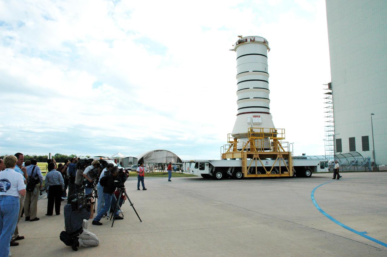
KENNEDY SPACE CENTER, FLA. - The media station their cameras to capture the move of the aft skirt and lower segment of the Solid Rocket Booster for the Return to Flight mission STS-114. A significant milestone in Return to Flight preparations, these first segments are moving from the Rotation Processing and Surge Facility to the Vehicle Assembly Building. Other segments will follow for stacking. Two SRBs support the liftoff of the Space Shuttle on a launch. The twin 149-foot tall, 12-foot diameter SRBs provide the main propulsion system during launch to place the 180,000-pound orbiters in the proper orbit around the Earth. They operate parallel with the Space Shuttle main engines for the first two minutes of flight and jettison away from the orbiter with help from the Booster Separation Motors, about 26.3 nautical miles above the Earth’s surface.
KENNEDY SPACE CENTER, FLA. - - The media station their cameras to capture the move of the aft skirt and lower segment of the Solid Rocket Booster for the Return to Flight mission STS-114. A significant milestone in Return to Flight, these first segments are moving from the Rotation Processing and Surge Facility to the Vehicle Assembly Building. Other segments will follow for stacking. Two SRBs support the liftoff of the Space Shuttle on a launch. The twin 149-foot tall, 12-foot diameter SRBs provide the main propulsion system during launch to place the 180,000-pound orbiters in the proper orbit around the Earth. They operate parallel with the Space Shuttle main engines for the first two minutes of flight and jettison away from the orbiter with help from the Booster Separation Motors, about 26.3 nautical miles above the Earth’s surface.
KENNEDY SPACE CENTER, FLA. - Workers in Hangar AF at Cape Canaveral Air Force Station take a look at one of the spent Solid Rocket Boosters (SRBs) from the launch of Space Shuttle Discovery July 26 on Return to Flight mission STS-114. The SRBs are the largest solid propellant motors ever flown and the first designed for reuse. After a Shuttle is launched, the SRBs are jettisoned at two minutes, seven seconds into the flight. At six minutes and 44 seconds after liftoff, the spent SRBs, weighing about 165,000 lb., have slowed their descent speed to about 62 mph and splashdown takes place in a predetermined area. They are retrieved from the Atlantic Ocean by special recovery vessels and returned for refurbishment and eventual reuse on future Shuttle flights. Once at Hangar AF, the SRBs are unloaded onto a hoisting slip and mobile gantry cranes lift them onto tracked dollies where they are safed and undergo their first washing.
KENNEDY SPACE CENTER, FLA. - In a Vehicle Assembly Building (VAB) high bay, an aft center segment of a Solid Rocket Booster (SRB) continues its descent toward an aft segment already secured to a Mobile Launch Platform. These segments are part of the right SRB for the Space Shuttle Return to Flight mission, STS-114. Two SRBs are stacked on a Mobile Launch Platform for each Shuttle flight and later joined by an External Tank. The twin 149-foot tall, 12-foot diameter SRBs provide the main propulsion system during launch. They operate in parallel with the Space Shuttle main engines for the first two minutes of flight and jettison away from the orbiter with help from the Booster Separation Motors, about 26.3 nautical miles above the Earth’s surface.
KENNEDY SPACE CENTER, FLA. - In a Vehicle Assembly Building (VAB) high bay, workers monitor the movement of a Solid Rocket Booster (SRB) aft center segment as it is lowered toward an aft segment already secured to a Mobile Launch Platform. These segments are part of the right SRB for the Space Shuttle Return to Flight mission, STS-114. Two SRBs are stacked on a Mobile Launch Platform for each Shuttle flight and later joined by an External Tank. The twin 149-foot tall, 12-foot diameter SRBs provide the main propulsion system during launch. They operate in parallel with the Space Shuttle main engines for the first two minutes of flight and jettison away from the orbiter with help from the Booster Separation Motors, about 26.3 nautical miles above the Earth’s surface.
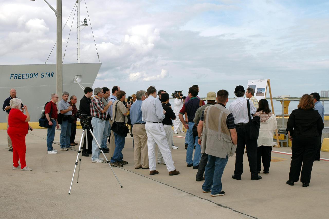
KENNEDY SPACE CENTER, FLA. - On the deck of the Freedom Star, one of the Solid Rocket Booster (SRB) retrieval ships, the media learn about retrieval operations. The stop was part of a day-long event that featured the movement of the first SRB segments to the Vehicle Assembly Building for stacking for Return to Flight mission STS-114. Two SRBs support the liftoff of the Space Shuttle on a launch. The twin 149-foot tall, 12-foot diameter SRBs provide the main propulsion system during launch to place the orbiters in the proper orbit around the Earth. They operate parallel with the Space Shuttle main engines for the first two minutes of flight and jettison away from the orbiter, with help from the Booster Separation Motors, about 26.3 nautical miles above the Earth’s surface.
KENNEDY SPACE CENTER, FLA. - The media tour the Solid Rocket Booster (SRB) Assembly and Refurbishment Facility where SRB segments are refurbished. In the background can be seen the frustum and nose cap of an SRB. The media event featured the movement of the first SRB segments to the Vehicle Assembly Building for stacking for Return to Flight mission STS-114. Two SRBs support the liftoff of the Space Shuttle on a launch. The twin 149-foot tall, 12-foot diameter SRBs provide the main propulsion system during launch to place the orbiters in the proper orbit around the Earth. They operate parallel with the Space Shuttle main engines for the first two minutes of flight and jettison away from the orbiter, with help from the Booster Separation Motors, about 26.3 nautical miles above the Earth’s surface.

KENNEDY SPACE CENTER, FLA. - The aft skirt and lower segment of the Solid Rocket Booster (SRB) being prepared for Return to Flight on mission STS-114 are being transported from the Rotation Processing and Surge Facility to the Vehicle Assembly Building. Other segments will be moved to the VAB later for stacking. Two SRBs support the liftoff of the Space Shuttle on a launch. The twin 149-foot tall, 12-foot diameter SRBs provide the main propulsion system during launch to place the 180,000-pound orbiters in the proper orbit around the Earth. They operate parallel with the Space Shuttle main engines for the first two minutes of flight and jettison away from the orbiter with help from the Booster Separation Motors, about 26.3 nautical miles above the Earth’s surface.
KENNEDY SPACE CENTER, FLA. - In the Vehicle Assembly Building (VAB), a segment of a Solid Rocket Booster (SRB) is lifted over the cross walk at the 16th level. This right aft center segment will be stacked with the aft booster on the other side that arrived in the VAB Nov. 22 for the Return to Flight mission STS-114. Two SRBs are stacked on the Mobile Launch Platform and later joined by the External Tank.. The twin 149-foot tall, 12-foot diameter SRBs provide the main propulsion system during launch. They operate parallel with the Space Shuttle main engines for the first two minutes of flight and jettison away from the orbiter with help from the Booster Separation Motors, about 26.3 nautical miles above the Earth’s surface.

KENNEDY SPACE CENTER, FLA. - This view from above shows the place where the Solid Rocket Booster (SRB) for the Return to Flight mission STS-114 will be stacked. The aft skirt and lower segment were transported to the VAB Nov. 22. In the background are media who are reporting on this significant milestone. Two SRBs support the liftoff of the Space Shuttle on a launch. The twin 149-foot tall, 12-foot diameter SRBs provide the main propulsion system during launch to place the 180,000-pound orbiters in the proper orbit around the Earth. They operate parallel with the Space Shuttle main engines for the first two minutes of flight and jettison away from the orbiter with help from the Booster Separation Motors, about 26.3 nautical miles above the Earth’s surface.
KENNEDY SPACE CENTER, FLA. - Inside the Vehicle Assembly Building, NASA ET_SRB Operations Manager Ken Tenbusch provides information for the media about the stacking of the aft skirt and lower segment of the Solid Rocket Booster in the background. These first segments are a significant milestone in the preparations for Return to Flight mission STS-114. Two SRBs support the liftoff of the Space Shuttle on a launch. The twin 149-foot tall, 12-foot diameter SRBs provide the main propulsion system during launch to place the 180,000-pound orbiters in the proper orbit around the Earth. They operate parallel with the Space Shuttle main engines for the first two minutes of flight and jettison away from the orbiter with help from the Booster Separation Motors, about 26.3 nautical miles above the Earth’s surface.
KENNEDY SPACE CENTER, FLA. - In the Vehicle Assembly Building (VAB), a segment of a Solid Rocket Booster (SRB) is lifted over the cross walk at the 16th level. This right aft center segment will be stacked with the aft booster on the other side that arrived in the VAB Nov. 22 for the Return to Flight mission STS-114. Two SRBs are stacked on the Mobile Launch Platform and later joined by the External Tank.. The twin 149-foot tall, 12-foot diameter SRBs provide the main propulsion system during launch. They operate parallel with the Space Shuttle main engines for the first two minutes of flight and jettison away from the orbiter with help from the Booster Separation Motors, about 26.3 nautical miles above the Earth’s surface.
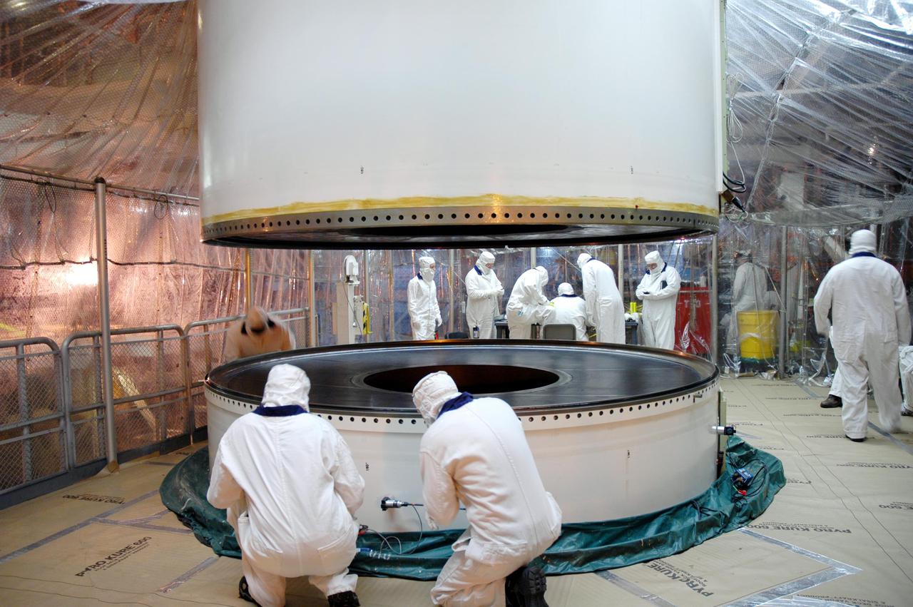
KENNEDY SPACE CENTER, FLA. - In a Vehicle Assembly Building (VAB) high bay, workers check the alignment of a Solid Rocket Booster (SRB) aft center segment which has been lowered onto an aft segment already secured to a Mobile Launch Platform. These segments are part of the right SRB for the Space Shuttle Return to Flight mission, STS-114. Two SRBs are stacked on a Mobile Launch Platform for each Shuttle flight and later joined by an External Tank. The twin 149-foot tall, 12-foot diameter SRBs provide the main propulsion system during launch. They operate in parallel with the Space Shuttle main engines for the first two minutes of flight and jettison away from the orbiter with help from the Booster Separation Motors, about 26.3 nautical miles above the Earth’s surface.
KENNEDY SPACE CENTER, FLA. - The media tour Hangar AF where Solid Rocket Booster (SRB) segments are refurbished (an aft skirt is in the background). The stop was part of a day-long event that featured the movement of the first SRB segments to the Vehicle Assembly Building for stacking for Return to Flight mission STS-114. Two SRBs support the liftoff of the Space Shuttle on a launch. The twin 149-foot tall, 12-foot diameter SRBs provide the main propulsion system during launch to place the orbiters in the proper orbit around the Earth. They operate parallel with the Space Shuttle main engines for the first two minutes of flight and jettison away from the orbiter, with help from the Booster Separation Motors, about 26.3 nautical miles above the Earth’s surface.
KENNEDY SPACE CENTER, FLA. - The aft skirt and lower segment of the Solid Rocket Booster (SRB) being prepared for Return to Flight on mission STS-114 approach the Vehicle Assembly Building. The segments will be prepared for stacking with the other segments arriving later. Two SRBs support the liftoff of the Space Shuttle on a launch. The twin 149-foot tall, 12-foot diameter SRBs provide the main propulsion system during launch to place the 180,000-pound orbiters in the proper orbit around the Earth. They operate parallel with the Space Shuttle main engines for the first two minutes of flight and jettison away from the orbiter with help from the Booster Separation Motors, about 26.3 nautical miles above the Earth’s surface.
A spent solid rocket booster (SRB) from the STS-87 launch on Nov. 19 is lifted in a hoisting slip in the Hangar AF area at Cape Canaveral Air Station. Hangar AF is a building originally used for Project Mercury, the first U.S. manned space program. The SRBs are the largest solid propellant motors ever flown and the first designed for reuse. After a Shuttle is launched, the SRBs are jettisoned at two minutes, seven seconds into the flight. At six minutes and 44 seconds after liftoff, the spent SRBs, weighing about 165,000 lb., have slowed their descent speed to about 62 mph and splashdown takes place in a predetermined area. They are retrieved from the Atlantic Ocean by special recovery vessels and returned for refurbishment and eventual reuse on future Shuttle flights. Once at Hangar AF, the SRBs are unloaded onto a hoisting slip and mobile gantry cranes lift them onto tracked dollies where they are safed and undergo their first washing

KENNEDY SPACE CENTER, FLA. - The media tour the Parachute Refurbishment Facility, which cleans and repairs the Solid Rocket Booster (SRB) parachutes after a Space Shuttle launch. The stop was part of a day-long event that featured the movement of the first SRB segments to the Vehicle Assembly Building for stacking for Return to Flight mission STS-114. Two SRBs support the liftoff of the Space Shuttle on a launch. The twin 149-foot tall, 12-foot diameter SRBs provide the main propulsion system during launch to place the orbiters in the proper orbit around the Earth. They operate parallel with the Space Shuttle main engines for the first two minutes of flight and jettison away from the orbiter, with help from the Booster Separation Motors, about 26.3 nautical miles above the Earth’s surface.
KENNEDY SPACE CENTER, FLA. - The aft skirt and lower segment of the Solid Rocket Booster (SRB) being prepared for Return to Flight on mission STS-114 approach the Vehicle Assembly Building. The segments will be prepared for stacking with the other segments arriving later. Two SRBs support the liftoff of the Space Shuttle on a launch. The twin 149-foot tall, 12-foot diameter SRBs provide the main propulsion system during launch to place the 180,000-pound orbiters in the proper orbit around the Earth. They operate parallel with the Space Shuttle main engines for the first two minutes of flight and jettison away from the orbiter with help from the Booster Separation Motors, about 26.3 nautical miles above the Earth’s surface.

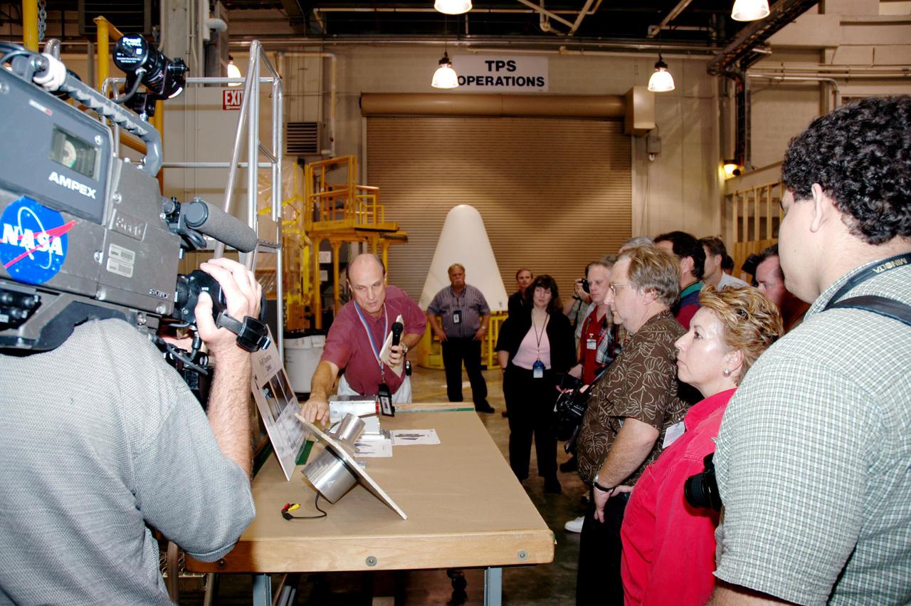
KENNEDY SPACE CENTER, FLA. - The media are shown parts of Solid Rocket Booster (SRB) segments in the SRB Assembly and Refurbishment Facility. The tour was part of a day-long event that featured the movement of the first SRB segments to the Vehicle Assembly Building for stacking for Return to Flight mission STS-114. Two SRBs support the liftoff of the Space Shuttle on a launch. The twin 149-foot tall, 12-foot diameter SRBs provide the main propulsion system during launch to place the orbiters in the proper orbit around the Earth. They operate parallel with the Space Shuttle main engines for the first two minutes of flight and jettison away from the orbiter, with help from the Booster Separation Motors, about 26.3 nautical miles above the Earth’s surface.
KENNEDY SPACE CENTER, FLA. - The media tour Solid Rocket Booster (SRB) Assembly and Refurbishment Facility where Solid Rocket Booster (SRB) segments are refurbished. In the background can be seen the frustum and nose cap of an SRB. The media event featured the movement of the first SRB segments to the Vehicle Assembly Building for stacking for Return to Flight mission STS-114. Two SRBs support the liftoff of the Space Shuttle on a launch. The twin 149-foot tall, 12-foot diameter SRBs provide the main propulsion system during launch to place the orbiters in the proper orbit around the Earth. They operate parallel with the Space Shuttle main engines for the first two minutes of flight and jettison away from the orbiter, with help from the Booster Separation Motors, about 26.3 nautical miles above the Earth’s surface.
KENNEDY SPACE CENTER, FLA. - In the Vehicle Assembly Building (VAB), media are shown where the Solid Rocket Booster (SRB) for the Return to Flight mission STS-114 will be stacked on the Mobile Launcher Platform. The aft skirt and lower segment segment have been transported from the Rotation Processing and Surge Facility to the VAB. Other segments will follow. Two SRBs support the liftoff of the Space Shuttle on a launch. The twin 149-foot tall, 12-foot diameter SRBs provide the main propulsion system during launch to place the 180,000-pound orbiters in the proper orbit around the Earth. They operate parallel with the Space Shuttle main engines for the first two minutes of flight and jettison away from the orbiter with help from the Booster Separation Motors, about 26.3 nautical miles above the Earth’s surface.
KENNEDY SPACE CENTER, FLA. - The aft skirt and lower segment of the Solid Rocket Booster (SRB) being prepared for Return to Flight on mission STS-114 leave the Rotation Processing and Surge Facility. The segments are being transported to the Vehicle Assembly Building where they will be prepared for stacking with the other segments arriving later. Two SRBs support the liftoff of the Space Shuttle on a launch. The twin 149-foot tall, 12-foot diameter SRBs provide the main propulsion system during launch to place the 180,000-pound orbiters in the proper orbit around the Earth. They operate parallel with the Space Shuttle main engines for the first two minutes of flight and jettison away from the orbiter with help from the Booster Separation Motors, about 26.3 nautical miles above the Earth’s surface.
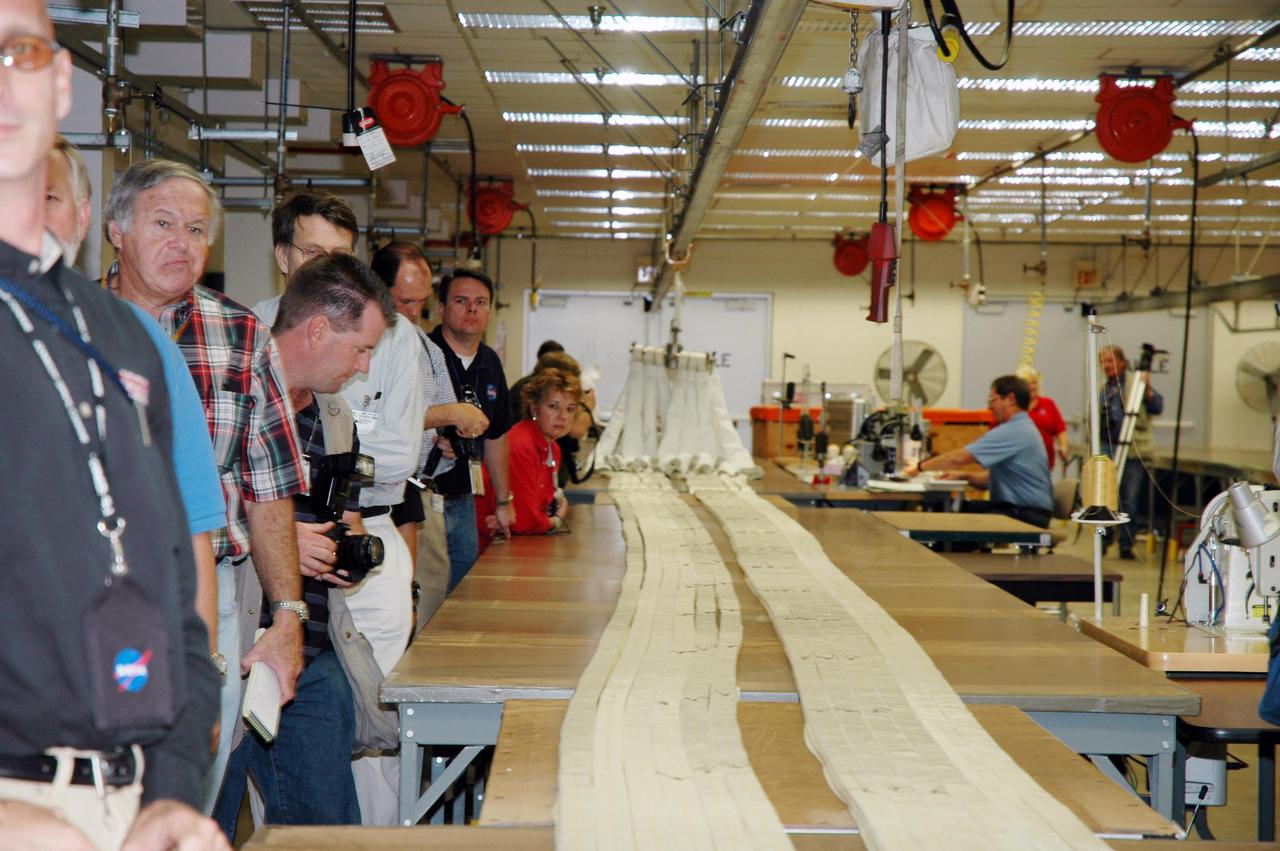
KENNEDY SPACE CENTER, FLA. - The media tour the Parachute Refurbishment Facility, which cleans and repairs the Solid Rocket Booster (SRB) parachutes after a Space Shuttle launch. The stop was part of a day-long event that featured the movement of the first SRB segments to the Vehicle Assembly Building for stacking for Return to Flight mission STS-114. Two SRBs support the liftoff of the Space Shuttle on a launch. The twin 149-foot tall, 12-foot diameter SRBs provide the main propulsion system during launch to place the orbiters in the proper orbit around the Earth. They operate parallel with the Space Shuttle main engines for the first two minutes of flight and jettison away from the orbiter, with help from the Booster Separation Motors, about 26.3 nautical miles above the Earth’s surface.
KENNEDY SPACE CENTER, FLA. - In a Vehicle Assembly Building (VAB) high bay, workers check the alignment of a Solid Rocket Booster (SRB) aft center segment as it is lowered toward an aft segment already secured to a Mobile Launch Platform. These segments are part of the right SRB for the Space Shuttle Return to Flight mission, STS-114. Two SRBs are stacked on a Mobile Launch Platform for each Shuttle flight and later joined by an External Tank. The twin 149-foot tall, 12-foot diameter SRBs provide the main propulsion system during launch. They operate in parallel with the Space Shuttle main engines for the first two minutes of flight and jettison away from the orbiter with help from the Booster Separation Motors, about 26.3 nautical miles above the Earth’s surface.
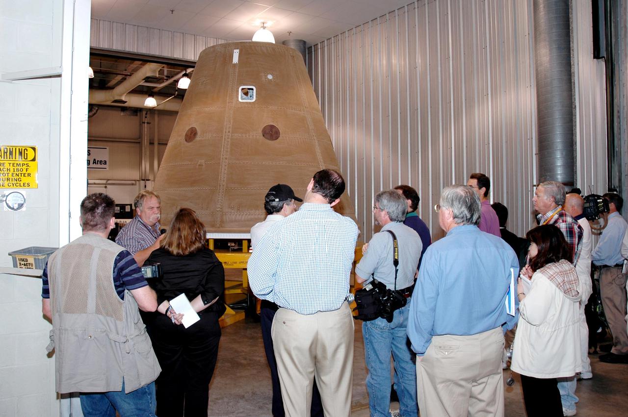
KENNEDY SPACE CENTER, FLA. - The media tour Solid Rocket Booster (SRB) Assembly and Refurbishment Facility where Solid Rocket Booster (SRB) segments are refurbished. In the background can be seen the frustum and nose cap of an SRB. The media event featured the movement of the first SRB segments to the Vehicle Assembly Building for stacking for Return to Flight mission STS-114. Two SRBs support the liftoff of the Space Shuttle on a launch. The twin 149-foot tall, 12-foot diameter SRBs provide the main propulsion system during launch to place the orbiters in the proper orbit around the Earth. They operate parallel with the Space Shuttle main engines for the first two minutes of flight and jettison away from the orbiter, with help from the Booster Separation Motors, about 26.3 nautical miles above the Earth’s surface.
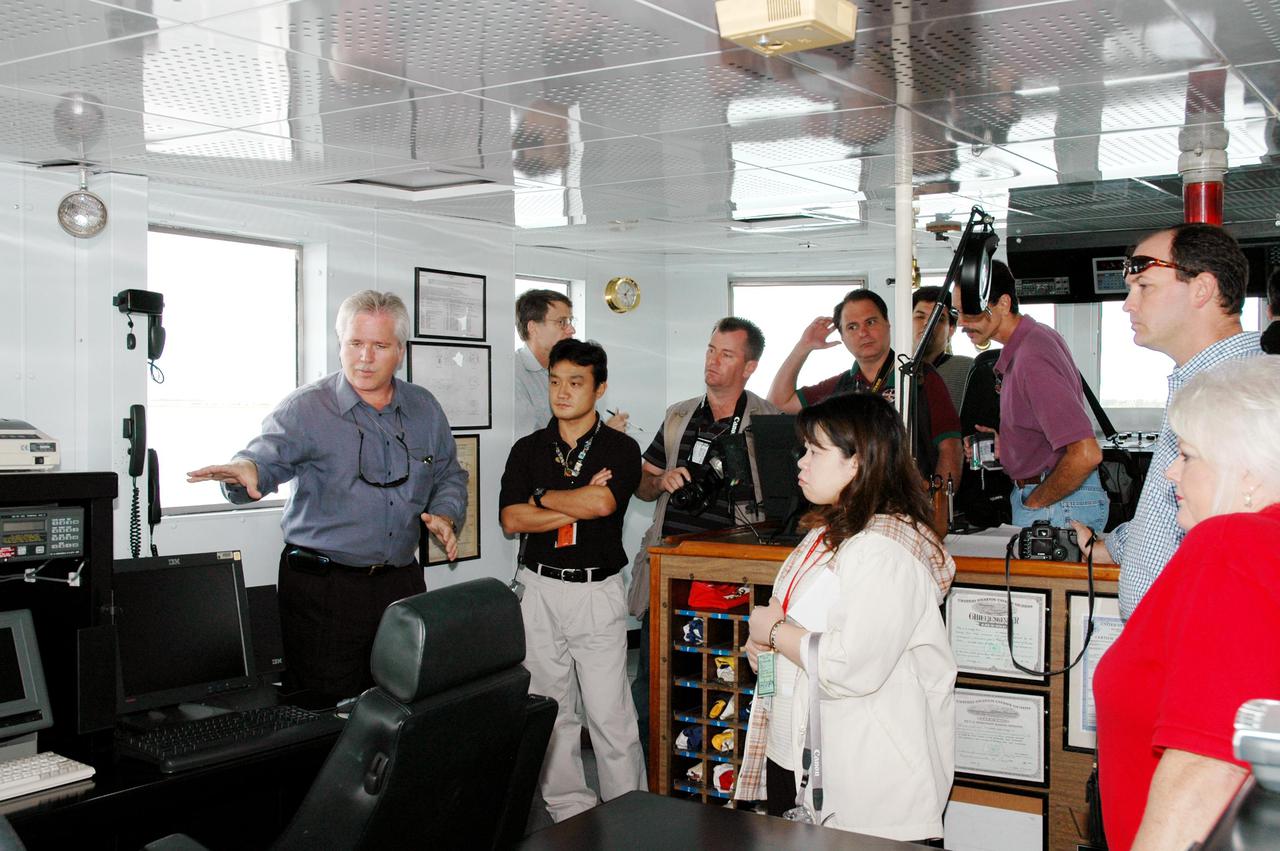
KENNEDY SPACE CENTER, FLA. - The media visit the operations center on board the Freedom Star, one of the Solid Rocket Booster (SRB) retrieval ships. The stop was part of a day-long event that featured the movement of the first SRB segments to the Vehicle Assembly Building for stacking for Return to Flight mission STS-114. Two SRBs support the liftoff of the Space Shuttle on a launch. The twin 149-foot tall, 12-foot diameter SRBs provide the main propulsion system during launch to place the orbiters in the proper orbit around the Earth. They operate parallel with the Space Shuttle main engines for the first two minutes of flight and jettison away from the orbiter, with help from the Booster Separation Motors, about 26.3 nautical miles above the Earth’s surface.
KENNEDY SPACE CENTER, FLA. - - The aft skirt and lower segment of the Solid Rocket Booster (SRB) being prepared for Return to Flight on mission STS-114 are being transported from the Rotation Processing and Surge Facility to the Vehicle Assembly Building. Other segments will be moved to the VAB later for stacking. Two SRBs support the liftoff of the Space Shuttle on a launch. The twin 149-foot tall, 12-foot diameter SRBs provide the main propulsion system during launch to place the 180,000-pound orbiters in the proper orbit around the Earth. They operate parallel with the Space Shuttle main engines for the first two minutes of flight and jettison away from the orbiter with help from the Booster Separation Motors, about 26.3 nautical miles above the Earth’s surface.
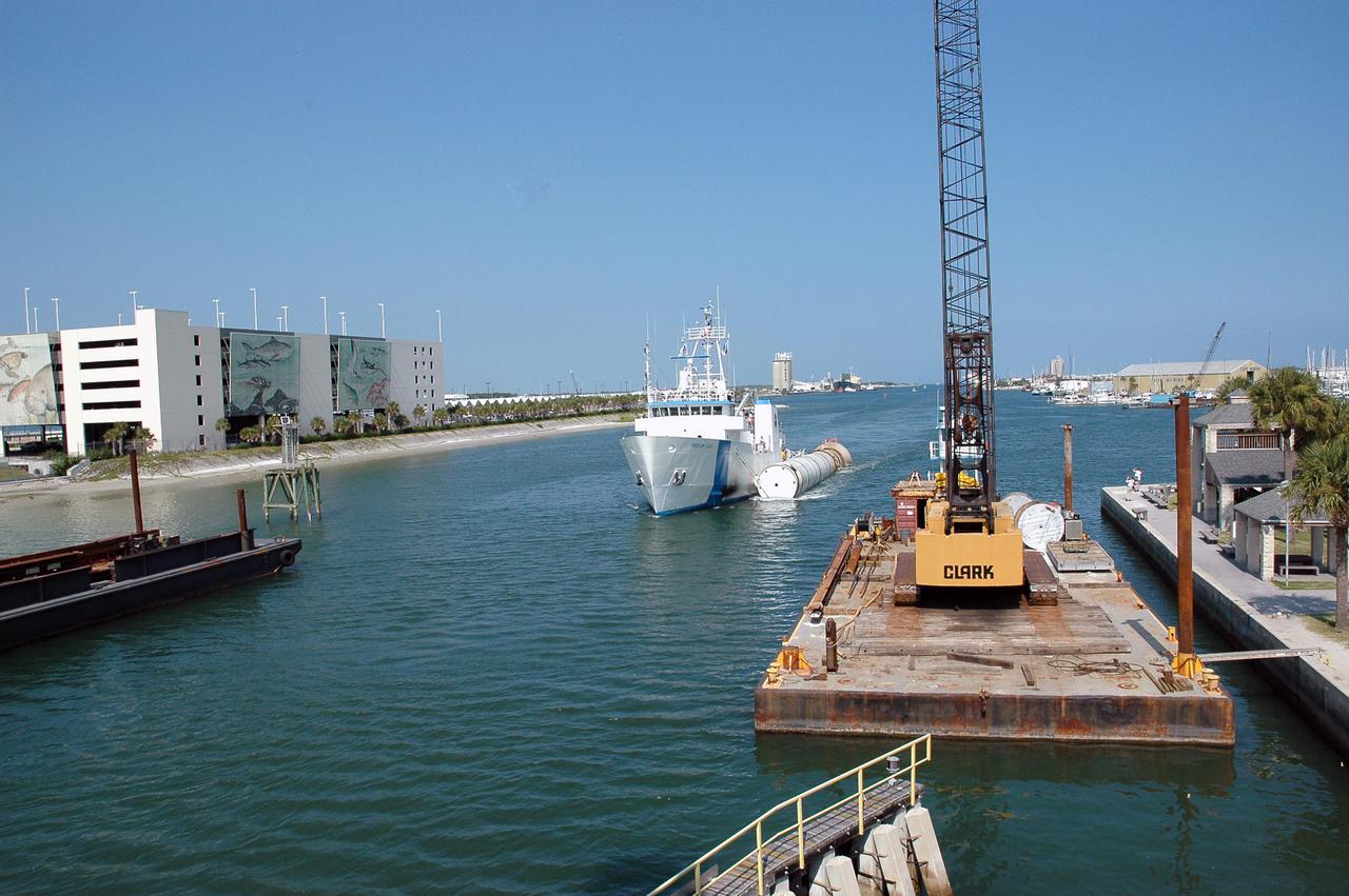
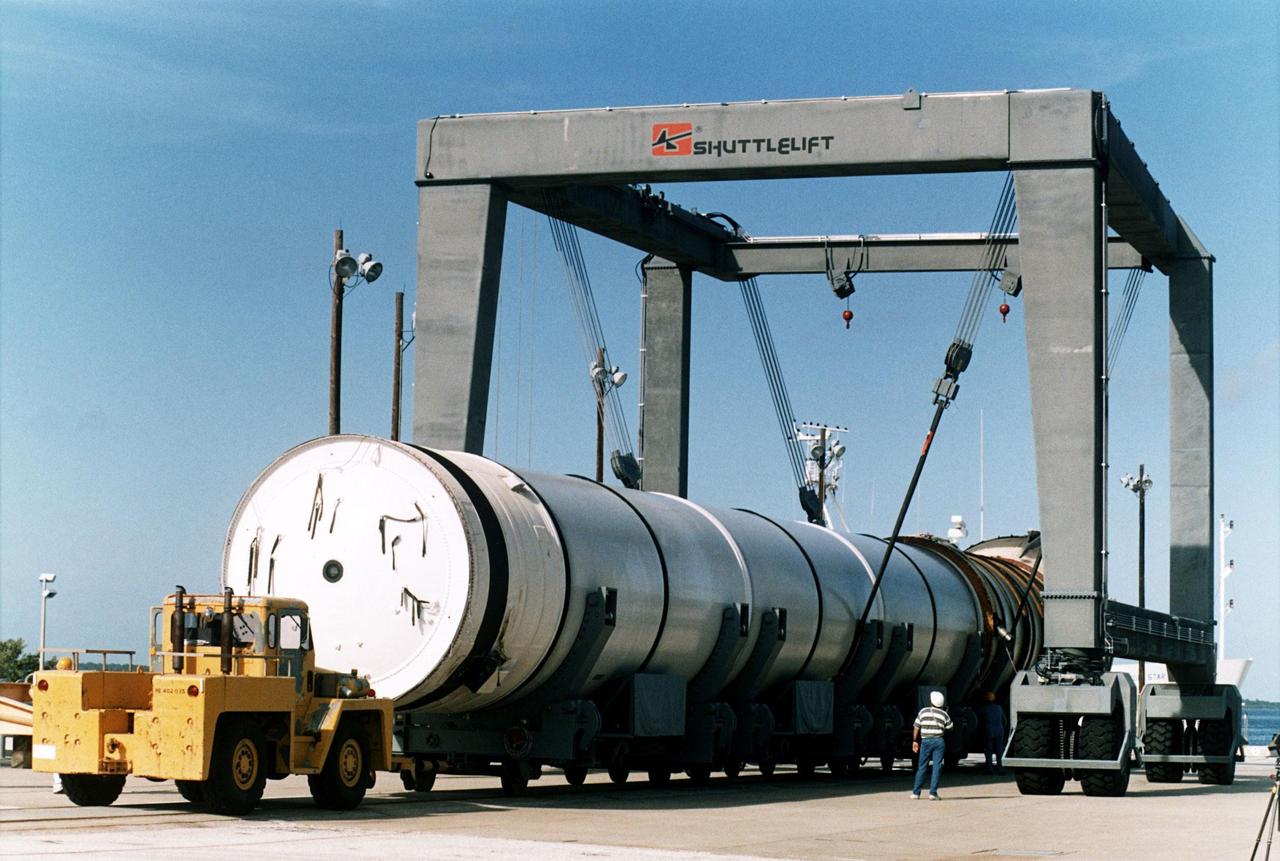
KENNEDY SPACE CENTER, FLA. - The solid rocket booster recovery ship Freedom Star makes its way through Port Canaveral with a spent solid rocket booster (SRB) from the STS-114 launch on July 26 in tow. The SRBs are the largest solid propellant motors ever flown and the first designed for reuse. After a Shuttle is launched, the SRBs are jettisoned at two minutes, seven seconds into the flight. At six minutes and 44 seconds after liftoff, the spent SRBs, weighing about 165,000 lb., have slowed their descent speed to about 62 mph and splashdown takes place in a predetermined area. They are retrieved from the Atlantic Ocean by special recovery vessels and returned for refurbishment and eventual reuse on future Shuttle flights. Once at Hangar AF, the SRBs are unloaded onto a hoisting slip and mobile gantry cranes lift them onto tracked dollies where they are safed and undergo their first washing.
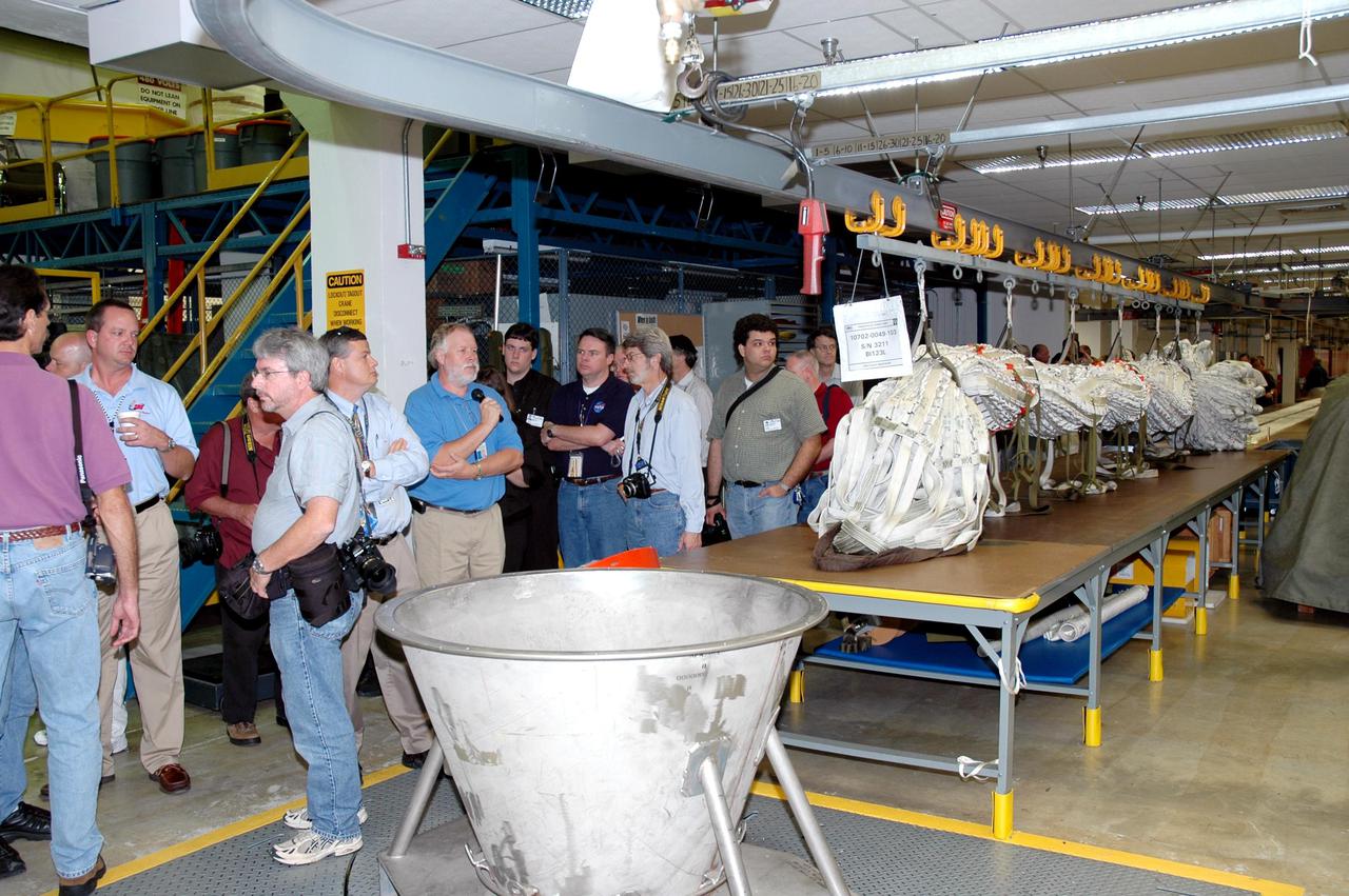
KENNEDY SPACE CENTER, FLA. - The media tour the Parachute Refurbishment Facility, which cleans and repairs the Solid Rocket Booster (SRB) parachutes after a Space Shuttle launch. The stop was part of a day-long event that featured the movement of the first SRB segments to the Vehicle Assembly Building for stacking for Return to Flight mission STS-114. Two SRBs support the liftoff of the Space Shuttle on a launch. The twin 149-foot tall, 12-foot diameter SRBs provide the main propulsion system during launch to place the orbiters in the proper orbit around the Earth. They operate parallel with the Space Shuttle main engines for the first two minutes of flight and jettison away from the orbiter, with help from the Booster Separation Motors, about 26.3 nautical miles above the Earth’s surface.
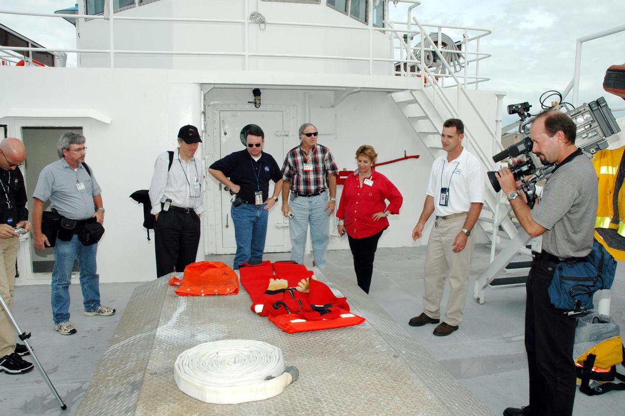
KENNEDY SPACE CENTER, FLA. - The media look at equipment on board one of the Solid Rocket Booster (SRB) retrieval ships. The stop was part of a day-long event that featured the movement of the first SRB segments to the Vehicle Assembly Building for stacking for Return to Flight mission STS-114. Two SRBs support the liftoff of the Space Shuttle on a launch. The twin 149-foot tall, 12-foot diameter SRBs provide the main propulsion system during launch to place the orbiters in the proper orbit around the Earth. They operate parallel with the Space Shuttle main engines for the first two minutes of flight and jettison away from the orbiter, with help from the Booster Separation Motors, about 26.3 nautical miles above the Earth’s surface.
A spent solid rocket booster (SRB) from the STS-87 launch on Nov. 19 is lifted in a hoisting slip in the Hangar AF area at Cape Canaveral Air Station. Hangar AF is a building originally used for Project Mercury, the first U.S. manned space program. The SRBs are the largest solid propellant motors ever flown and the first designed for reuse. After a Shuttle is launched, the SRBs are jettisoned at two minutes, seven seconds into the flight. At six minutes and 44 seconds after liftoff, the spent SRBs, weighing about 165,000 lb., have slowed their descent speed to about 62 mph and splashdown takes place in a predetermined area. They are retrieved from the Atlantic Ocean by special recovery vessels and returned for refurbishment and eventual reuse on future Shuttle flights. Once at Hangar AF, the SRBs are unloaded onto a hoisting slip and mobile gantry cranes lift them onto tracked dollies where they are safed and undergo their first washing
KENNEDY SPACE CENTER, FLA. - In the transfer aisle of the Vehicle Assembly Building (VAB), a segment of a Solid Rocket Booster (SRB) is lifted from a transporter toward the 16th level. This right aft center segment will be stacked with the aft booster that arrived in the VAB Nov. 22 for the Return to Flight mission STS-114. Two SRBs are stacked on the Mobile Launch Platform and later joined by the External Tank.. The twin 149-foot tall, 12-foot diameter SRBs provide the main propulsion system during launch. They operate parallel with the Space Shuttle main engines for the first two minutes of flight and jettison away from the orbiter with help from the Booster Separation Motors, about 26.3 nautical miles above the Earth’s surface.
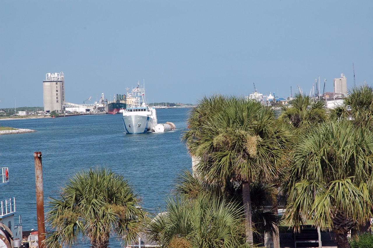
KENNEDY SPACE CENTER, FLA. - The solid rocket booster recovery ship Freedom Star enters Port Canaveral with a spent solid rocket booster (SRB) from the STS-114 launch on July 26 in tow. The SRBs are the largest solid propellant motors ever flown and the first designed for reuse. After a Shuttle is launched, the SRBs are jettisoned at two minutes, seven seconds into the flight. At six minutes and 44 seconds after liftoff, the spent SRBs, weighing about 165,000 lb., have slowed their descent speed to about 62 mph and splashdown takes place in a predetermined area. They are retrieved from the Atlantic Ocean by special recovery vessels and returned for refurbishment and eventual reuse on future Shuttle flights. Once at Hangar AF, the SRBs are unloaded onto a hoisting slip and mobile gantry cranes lift them onto tracked dollies where they are safed and undergo their first washing.
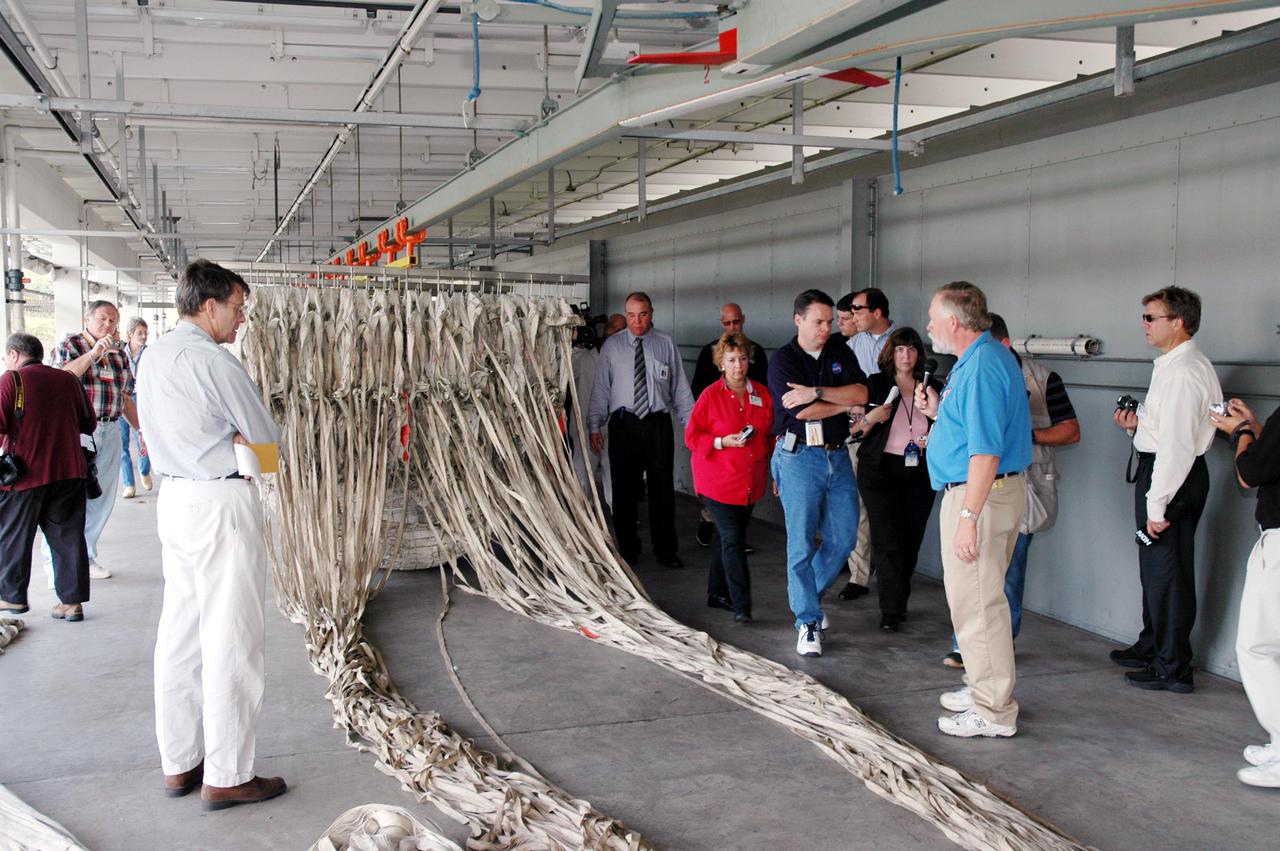
KENNEDY SPACE CENTER, FLA. - The media tour the Parachute Refurbishment Facility, which cleans and repairs the Solid Rocket Booster (SRB) parachutes after a Space Shuttle launch. The stop was part of a day-long event that featured the movement of the first SRB segments to the Vehicle Assembly Building for stacking for Return to Flight mission STS-114. Two SRBs support the liftoff of the Space Shuttle on a launch. The twin 149-foot tall, 12-foot diameter SRBs provide the main propulsion system during launch to place the orbiters in the proper orbit around the Earth. They operate parallel with the Space Shuttle main engines for the first two minutes of flight and jettison away from the orbiter, with help from the Booster Separation Motors, about 26.3 nautical miles above the Earth’s surface.

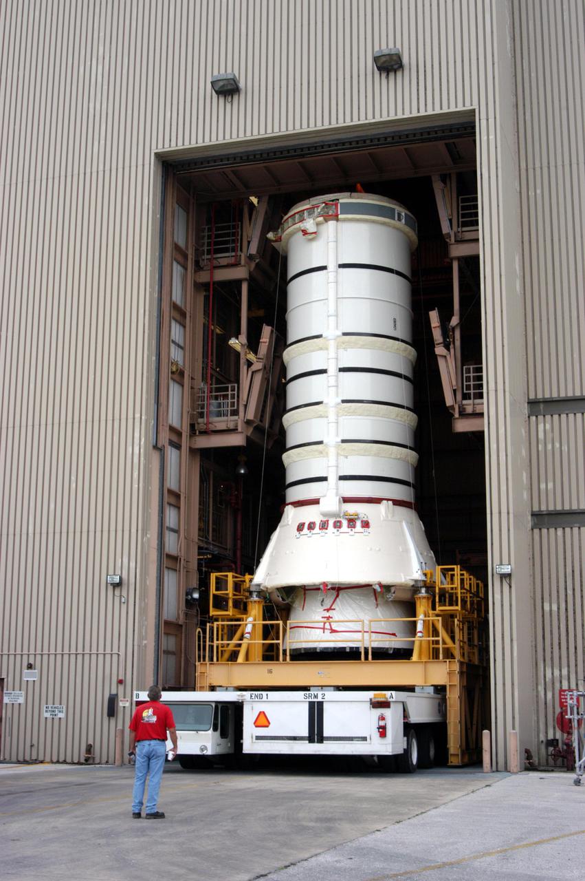
KENNEDY SPACE CENTER, FLA. - The aft skirt and lower segment of the Solid Rocket Booster (SRB) being prepared for Return to Flight on mission STS-114 move through the open doors of the Vehicle Assembly Building. The segments will be prepared for stacking with the other segments arriving later. Two SRBs support the liftoff of the Space Shuttle on a launch. The twin 149-foot tall, 12-foot diameter SRBs provide the main propulsion system during launch to place the 180,000-pound orbiters in the proper orbit around the Earth. They operate parallel with the Space Shuttle main engines for the first two minutes of flight and jettison away from the orbiter with help from the Booster Separation Motors, about 26.3 nautical miles above the Earth’s surface.
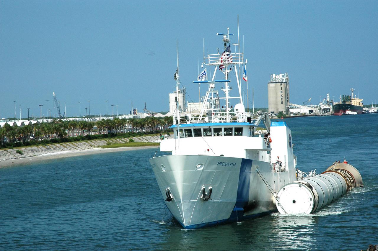
KENNEDY SPACE CENTER, FLA. - The solid rocket booster recovery ship Freedom Star travels through Port Canaveral with a spent solid rocket booster (SRB) from the STS-114 launch on July 26 in tow. The SRBs are the largest solid propellant motors ever flown and the first designed for reuse. After a Shuttle is launched, the SRBs are jettisoned at two minutes, seven seconds into the flight. At six minutes and 44 seconds after liftoff, the spent SRBs, weighing about 165,000 lb., have slowed their descent speed to about 62 mph and splashdown takes place in a predetermined area. They are retrieved from the Atlantic Ocean by special recovery vessels and returned for refurbishment and eventual reuse on future Shuttle flights. Once at Hangar AF, the SRBs are unloaded onto a hoisting slip and mobile gantry cranes lift them onto tracked dollies where they are safed and undergo their first washing.
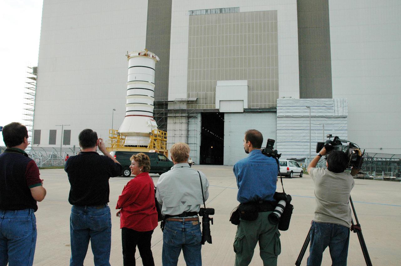
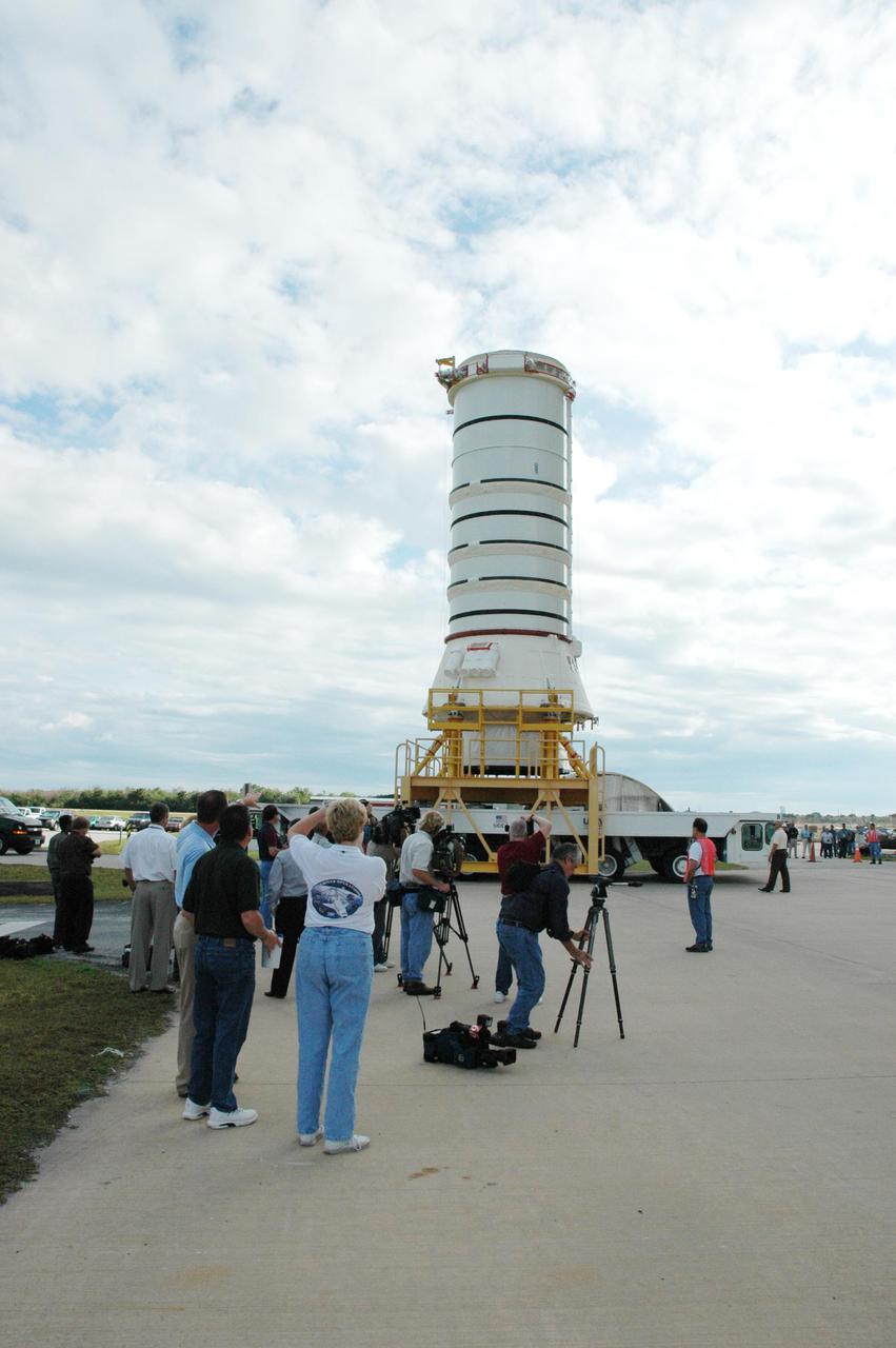
KENNEDY SPACE CENTER, FLA. - Photographers shoot the movement of the aft skirt and lower segment of the Solid Rocket Booster for the Return to Flight mission STS-114 as it nears the Vehicle Assembly Building. This is a significant milestone in Return to Flight preparations. Other segments will follow for stacking. Two SRBs support the liftoff of the Space Shuttle on a launch. The twin 149-foot tall, 12-foot diameter SRBs provide the main propulsion system during launch to place the 180,000-pound orbiters in the proper orbit around the Earth. They operate parallel with the Space Shuttle main engines for the first two minutes of flight and jettison away from the orbiter with help from the Booster Separation Motors, about 26.3 nautical miles above the Earth’s surface.
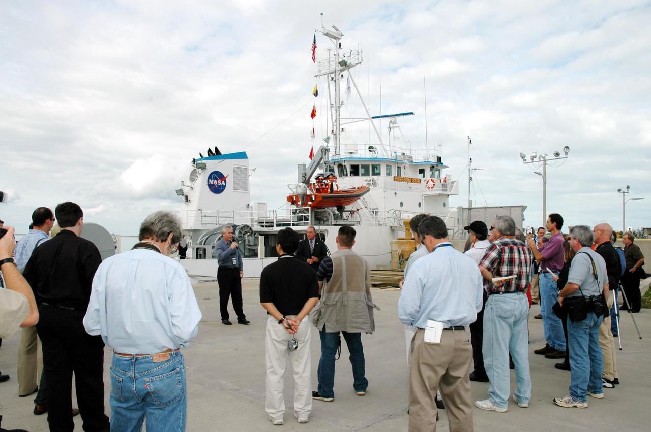
KENNEDY SPACE CENTER, FLA. - The media visit the docks where Solid Rocket Booster (SRB) retrieval ships are stationed. The stop was part of a day-long event that featured the movement of the first SRB segments to the Vehicle Assembly Building for stacking for Return to Flight mission STS-114. Two SRBs support the liftoff of the Space Shuttle on a launch. The twin 149-foot tall, 12-foot diameter SRBs provide the main propulsion system during launch to place the orbiters in the proper orbit around the Earth. They operate parallel with the Space Shuttle main engines for the first two minutes of flight and jettison away from the orbiter, with help from the Booster Separation Motors, about 26.3 nautical miles above the Earth’s surface.
KENNEDY SPACE CENTER, FLA. - The aft skirt and lower segment of the Solid Rocket Booster (SRB) being prepared for Return to Flight on mission STS-114 arrive inside the Vehicle Assembly Building. The segments will be prepared for stacking with the other segments arriving later. Two SRBs support the liftoff of the Space Shuttle on a launch. The twin 149-foot tall, 12-foot diameter SRBs provide the main propulsion system during launch to place the 180,000-pound orbiters in the proper orbit around the Earth. They operate parallel with the Space Shuttle main engines for the first two minutes of flight and jettison away from the orbiter with help from the Booster Separation Motors, about 26.3 nautical miles above the Earth’s surface.
KENNEDY SPACE CENTER, FLA. - In a Vehicle Assembly Building (VAB) high bay, an aft center segment of a Solid Rocket Booster (SRB) is moments away from contact with an aft segment already secured to a Mobile Launch Platform. These segments are part of the right SRB for the Space Shuttle Return to Flight mission, STS-114. Two SRBs are stacked on a Mobile Launch Platform for each Shuttle flight and later joined by an External Tank. The twin 149-foot tall, 12-foot diameter SRBs provide the main propulsion system during launch. They operate in parallel with the Space Shuttle main engines for the first two minutes of flight and jettison away from the orbiter with help from the Booster Separation Motors, about 26.3 nautical miles above the Earth’s surface.
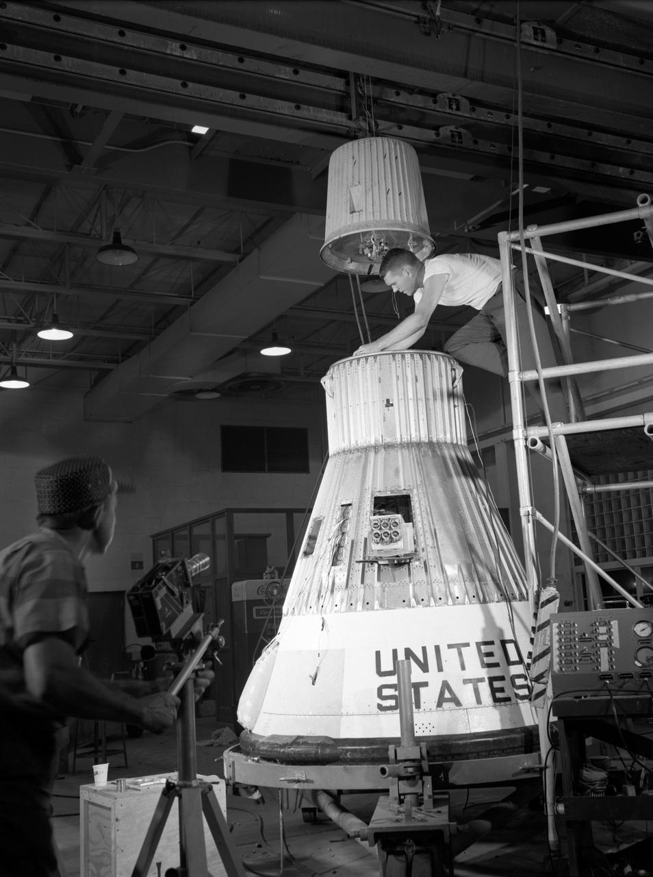
Technicians attach the escape tower to the Mercury capsule prior to assembly with Little Joe launcher, August 20, 1959. Joseph Shortal describe this as follows (vol. 3., p. 33): The escape tower and rocket motors were taken from the Mercury capsule production. The tower is shown being attached to the capsule.... The escape rocket was a Grand Central 1-KS-52000 motor with three canted nozzles. The tower-jettison motor was an Atlantic Research Corp. 1.4-KS-785 motor. This was the same design tested in a beach abort test...and had the offset thrust line as used in the beach abort test to insure that the capsule would get away from the booster in an emergency. The escape system weighed 1,015 pounds, including 236 pounds of ballast for stability. The Little Joe booster was assembled at Wallops on its special launcher in a vertical attitude. It is shown in the on the left with the work platform in place. The launcher was located on a special concrete slab in Launching Area 1. The capsule was lowered onto the booster by crane.... After the assembly was completed, the scaffolding was disassembled and the launcher pitched over to its normal launch angle of 80 degrees.... Little Joe had a diameter of 80 inches and an overall length, including the capsule and escape tower of 48 feet. The total weight at launch was about 43,000 pounds. The overall span of the stabilizing fins was 21.3 feet. Although in comparison with the overall Mercury Project, Little Joe was a simple undertaking, the fact that an attempt was made to condense a normal two-year project into a 6-month one with in house labor turned it into a major undertaking for Langley. -- Published in Joseph A. Shortal, History of Wallops Station: Origins and Activities Through 1949, (Wallops Island, VA: National Aeronautics and Space Administration, Wallops Station, nd), Comment Edition.
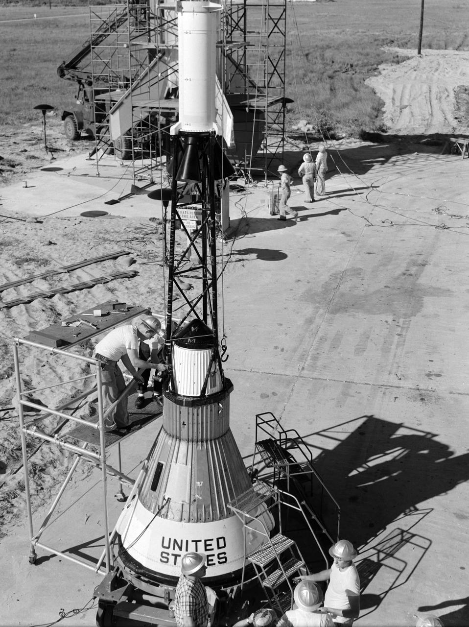
Technicians attach the escape tower to the Mercury capsule prior to assembly with Little Joe launcher, August 20, 1959. Joseph Shortal describe this as follows (vol. 3., p. 33): The escape tower and rocket motors were taken from the Mercury capsule production. The tower is shown being attached to the capsule.... The escape rocket was a Grand Central 1-KS-52000 motor with three canted nozzles. The tower-jettison motor was an Atlantic Research Corp. 1.4-KS-785 motor. This was the same design tested in a beach abort test...and had the offset thrust line as used in the beach abort test to insure that the capsule would get away from the booster in an emergency. The escape system weighed 1,015 pounds, including 236 pounds of ballast for stability. The Little Joe booster was assembled at Wallops on its special launcher in a vertical attitude. It is shown in the on the left with the work platform in place. The launcher was located on a special concrete slab in Launching Area 1. The capsule was lowered onto the booster by crane.... After the assembly was completed, the scaffolding was disassembled and the launcher pitched over to its normal launch angle of 80 degrees.... Little Joe had a diameter of 80 inches and an overall length, including the capsule and escape tower of 48 feet. The total weight at launch was about 43,000 pounds. The overall span of the stabilizing fins was 21.3 feet. Although in comparison with the overall Mercury Project, Little Joe was a simple undertaking, the fact that an attempt was made to condense a normal two-year project into a 6-month one with in house labor turned it into a major undertaking for Langley. -- Published in Joseph A. Shortal, History of Wallops Station: Origins and Activities Through 1949, (Wallops Island, VA: National Aeronautics and Space Administration, Wallops Station, nd), Comment Edition.
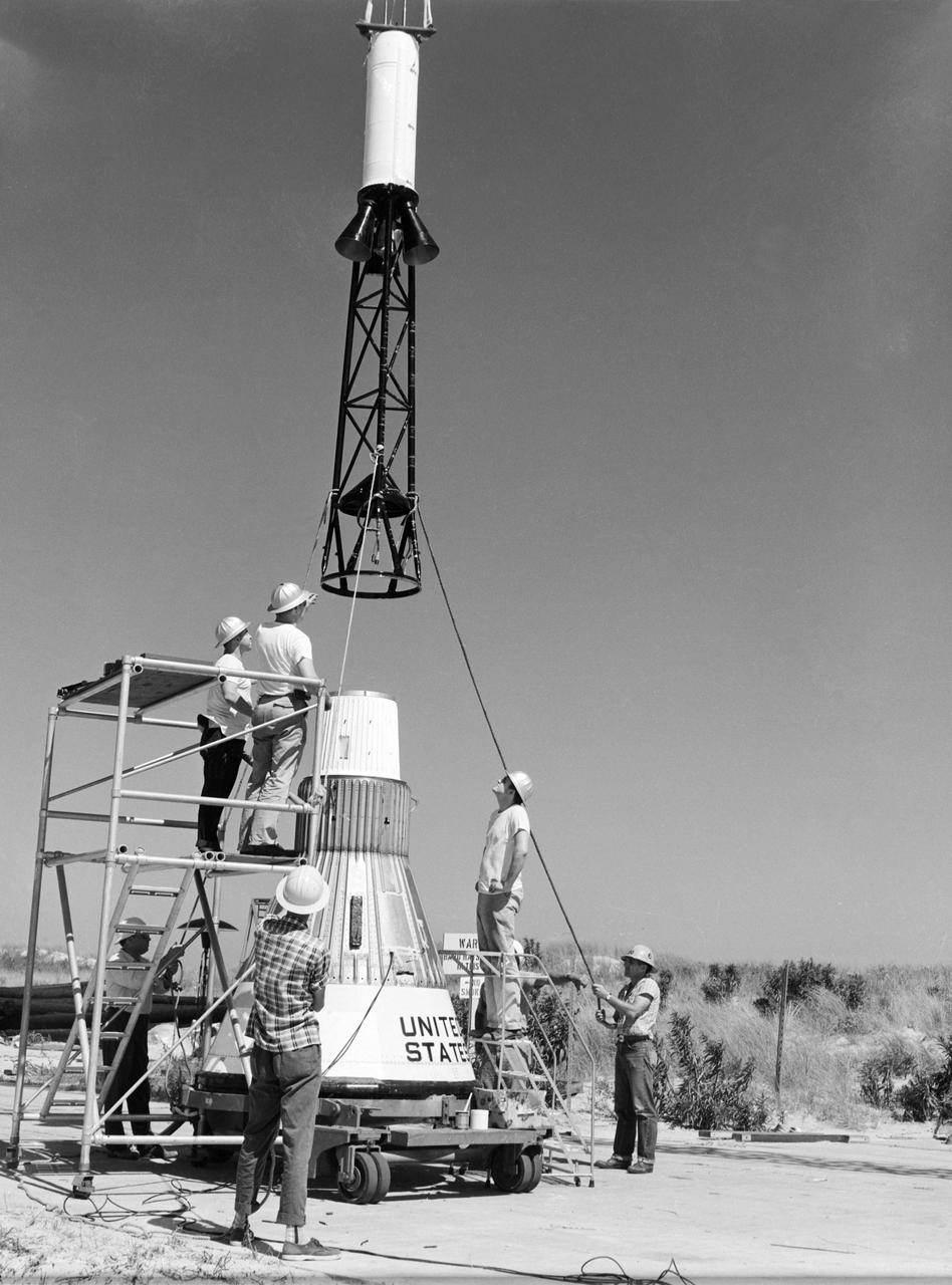
Technicians attach the escape tower to the Mercury capsule prior to assembly with Little Joe launcher, August 20, 1959. Joseph Shortal describe this as follows (vol. 3., p. 33): The escape tower and rocket motors were taken from the Mercury capsule production. The tower is shown being attached to the capsule.... The escape rocket was a Grand Central 1-KS-52000 motor with three canted nozzles. The tower-jettison motor was an Atlantic Research Corp. 1.4-KS-785 motor. This was the same design tested in a beach abort test...and had the offset thrust line as used in the beach abort test to insure that the capsule would get away from the booster in an emergency. The escape system weighed 1,015 pounds, including 236 pounds of ballast for stability. The Little Joe booster was assembled at Wallops on its special launcher in a vertical attitude. It is shown in the on the left with the work platform in place. The launcher was located on a special concrete slab in Launching Area 1. The capsule was lowered onto the booster by crane.... After the assembly was completed, the scaffolding was disassembled and the launcher pitched over to its normal launch angle of 80 degrees.... Little Joe had a diameter of 80 inches and an overall length, including the capsule and escape tower of 48 feet. The total weight at launch was about 43,000 pounds. The overall span of the stabilizing fins was 21.3 feet. Although in comparison with the overall Mercury Project, Little Joe was a simple undertaking, the fact that an attempt was made to condense a normal two-year project into a 6-month one with in house labor turned it into a major undertaking for Langley. -- Published in Joseph A. Shortal, History of Wallops Station: Origins and Activities Through 1949, (Wallops Island, VA: National Aeronautics and Space Administration, Wallops Station, nd), Comment Edition.
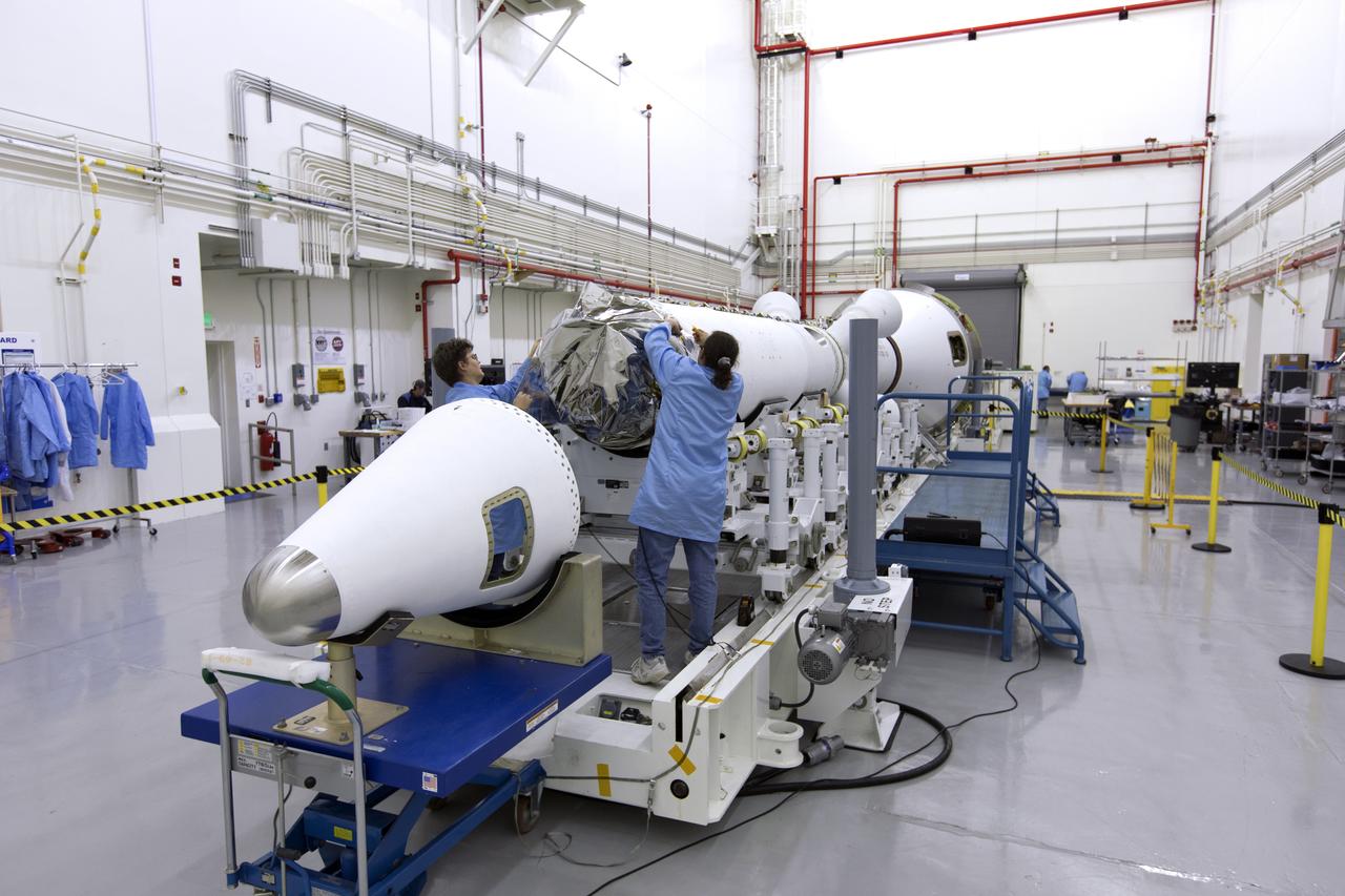
Inside the Launch Abort System Facility (LASF) at NASA’s Kennedy Space Center in Florida, workers assemble the Launch Abort System (LAS) on Feb. 5, 2019, that will be used for the Orion Ascent Abort-2 (AA-2) Flight Test. AA-2 is a full-stress test of the LAS, scheduled for Spring 2019. AA-2 will launch from Space Launch Complex 46, carrying a fully functional LAS and a 22,000-pound Orion test vehicle to an altitude of 31,000 feet and traveling at more than 1,000 miles an hour. The test will verify the LAS can steer the crew module and astronauts aboard to safety in the event of an issue with the Space Launch System (SLS) rocket when the spacecraft is under the highest aerodynamic loads it will experience during a rapid climb into space. NASA's Orion and Exploration Ground Systems programs and contractors from Jacob's and Northrop Grumman in conjunction with the Air Force Space and Missile Center's Launch Operations branch are performing flight operations for AA-2.
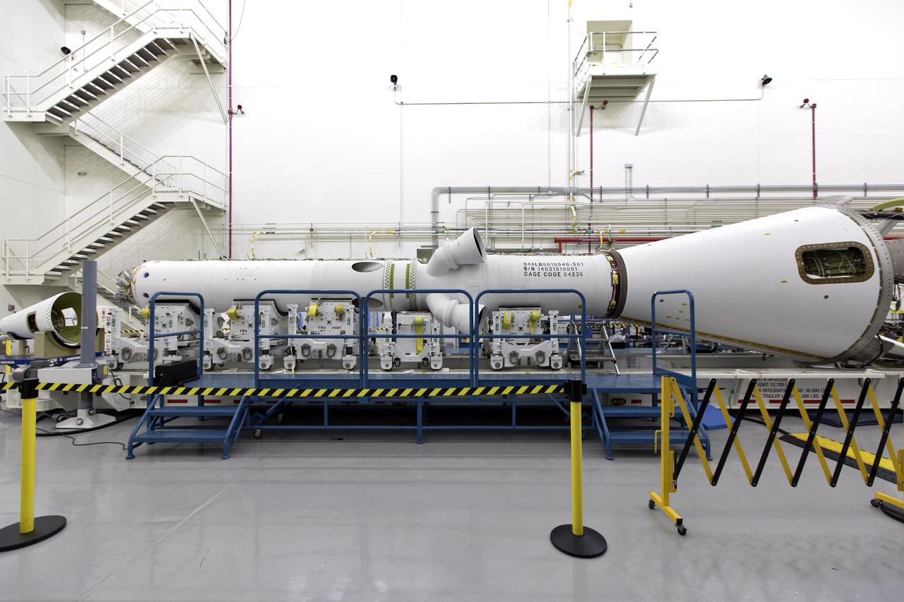
Inside the Launch Abort System Facility (LASF) at NASA’s Kennedy Space Center in Florida, the Launch Abort System (LAS) that will be used for the Orion Ascent Abort-2 (AA-2) Flight Test is being assembled on Feb. 5, 2019. AA-2 is a full-stress test of the LAS, scheduled for Spring 2019. AA-2 will launch from Space Launch Complex 46, carrying a fully functional LAS and a 22,000-pound Orion test vehicle to an altitude of 31,000 feet and traveling at more than 1,000 miles an hour. The test will verify the LAS can steer the crew module and astronauts aboard to safety in the event of an issue with the Space Launch System (SLS) rocket when the spacecraft is under the highest aerodynamic loads it will experience during a rapid climb into space. NASA's Orion and Exploration Ground Systems programs and contractors from Jacob's and Northrop Grumman in conjunction with the Air Force Space and Missile Center's Launch Operations branch are performing flight operations for AA-2.
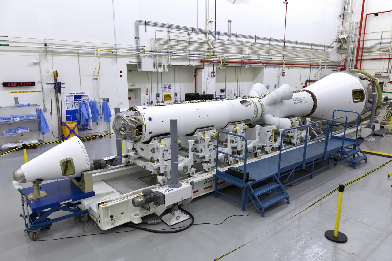
Inside the Launch Abort System Facility (LASF) at NASA’s Kennedy Space Center in Florida, the Launch Abort System (LAS) that will be used for the Orion Ascent Abort-2 (AA-2) Flight Test is being assembled on Feb. 5, 2019. AA-2 is a full-stress test of the LAS, scheduled for Spring 2019. AA-2 will launch from Space Launch Complex 46, carrying a fully functional LAS and a 22,000-pound Orion test vehicle to an altitude of 31,000 feet and traveling at more than 1,000 miles an hour. The test will verify the LAS can steer the crew module and astronauts aboard to safety in the event of an issue with the Space Launch System (SLS) rocket when the spacecraft is under the highest aerodynamic loads it will experience during a rapid climb into space. NASA's Orion and Exploration Ground Systems programs and contractors from Jacob's and Northrop Grumman in conjunction with the Air Force Space and Missile Center's Launch Operations branch are performing flight operations for AA-2.
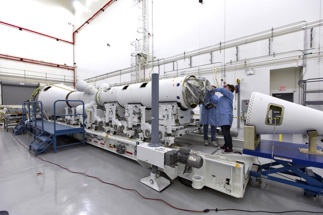
Inside the Launch Abort System Facility (LASF) at NASA’s Kennedy Space Center in Florida, workers assemble the Launch Abort System (LAS) on Feb. 5, 2019, that will be used for the Orion Ascent Abort-2 (AA-2) Flight Test. AA-2 is a full-stress test of the LAS, scheduled for Spring 2019. AA-2 will launch from Space Launch Complex 46, carrying a fully functional LAS and a 22,000-pound Orion test vehicle to an altitude of 31,000 feet and traveling at more than 1,000 miles an hour. The test will verify the LAS can steer the crew module and astronauts aboard to safety in the event of an issue with the Space Launch System (SLS) rocket when the spacecraft is under the highest aerodynamic loads it will experience during a rapid climb into space. NASA's Orion and Exploration Ground Systems programs and contractors from Jacob's and Northrop Grumman in conjunction with the Air Force Space and Missile Center's Launch Operations branch are performing flight operations for AA-2.
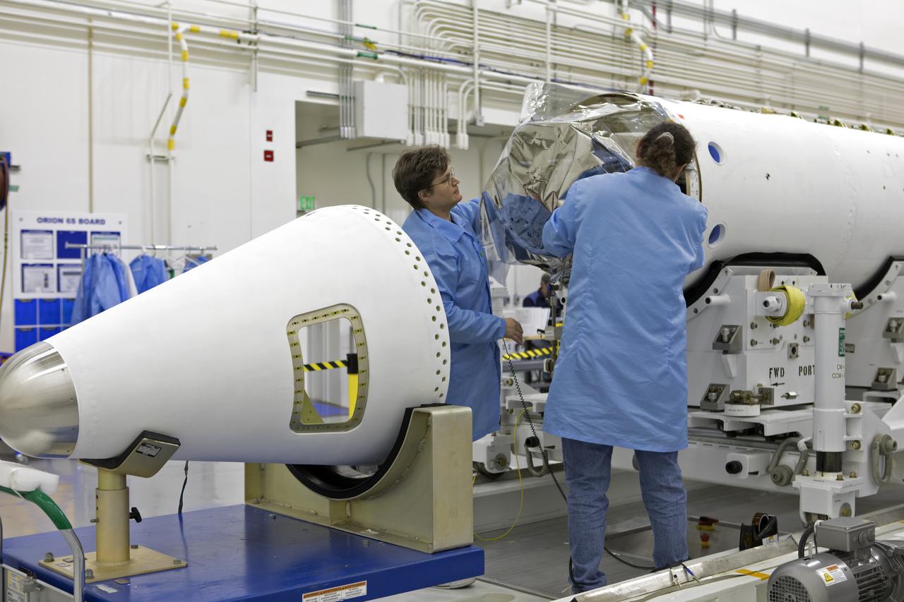
Inside the Launch Abort System Facility (LASF) at NASA’s Kennedy Space Center in Florida, workers assemble the Launch Abort System (LAS) on Feb. 5, 2019, that will be used for the Orion Ascent Abort-2 (AA-2) Flight Test. AA-2 is a full-stress test of the LAS, scheduled for Spring 2019. AA-2 will launch from Space Launch Complex 46, carrying a fully functional LAS and a 22,000-pound Orion test vehicle to an altitude of 31,000 feet and traveling at more than 1,000 miles an hour. The test will verify the LAS can steer the crew module and astronauts aboard to safety in the event of an issue with the Space Launch System (SLS) rocket when the spacecraft is under the highest aerodynamic loads it will experience during a rapid climb into space. NASA's Orion and Exploration Ground Systems programs and contractors from Jacob's and Northrop Grumman in conjunction with the Air Force Space and Missile Center's Launch Operations branch are performing flight operations for AA-2.
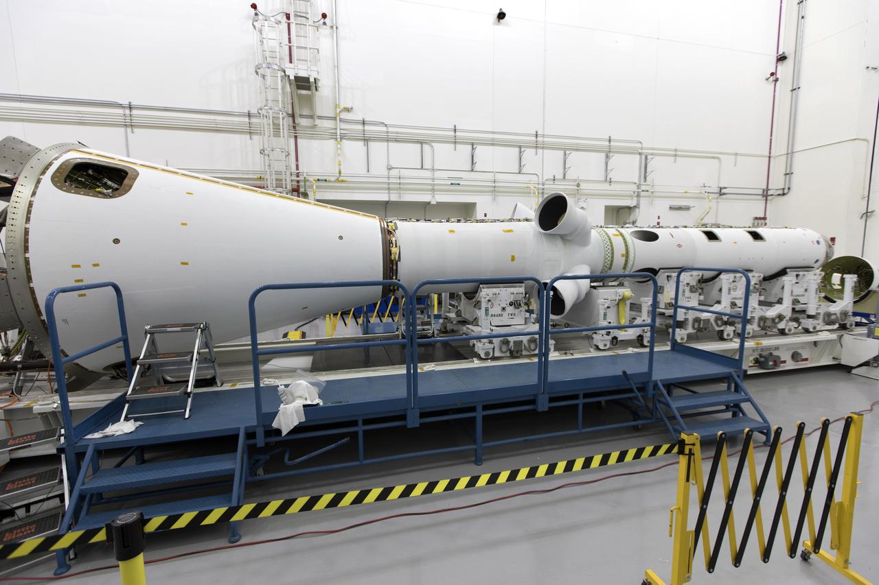
Inside the Launch Abort System Facility (LASF) at NASA’s Kennedy Space Center in Florida, the Launch Abort System (LAS) that will be used for the Orion Ascent Abort-2 (AA-2) Flight Test is being assembled on Feb. 5, 2019. AA-2 is a full-stress test of the LAS, scheduled for Spring 2019. AA-2 will launch from Space Launch Complex 46, carrying a fully functional LAS and a 22,000-pound Orion test vehicle to an altitude of 31,000 feet and traveling at more than 1,000 miles an hour. The test will verify the LAS can steer the crew module and astronauts aboard to safety in the event of an issue with the Space Launch System (SLS) rocket when the spacecraft is under the highest aerodynamic loads it will experience during a rapid climb into space. NASA's Orion and Exploration Ground Systems programs and contractors from Jacob's and Northrop Grumman in conjunction with the Air Force Space and Missile Center's Launch Operations branch are performing flight operations for AA-2.
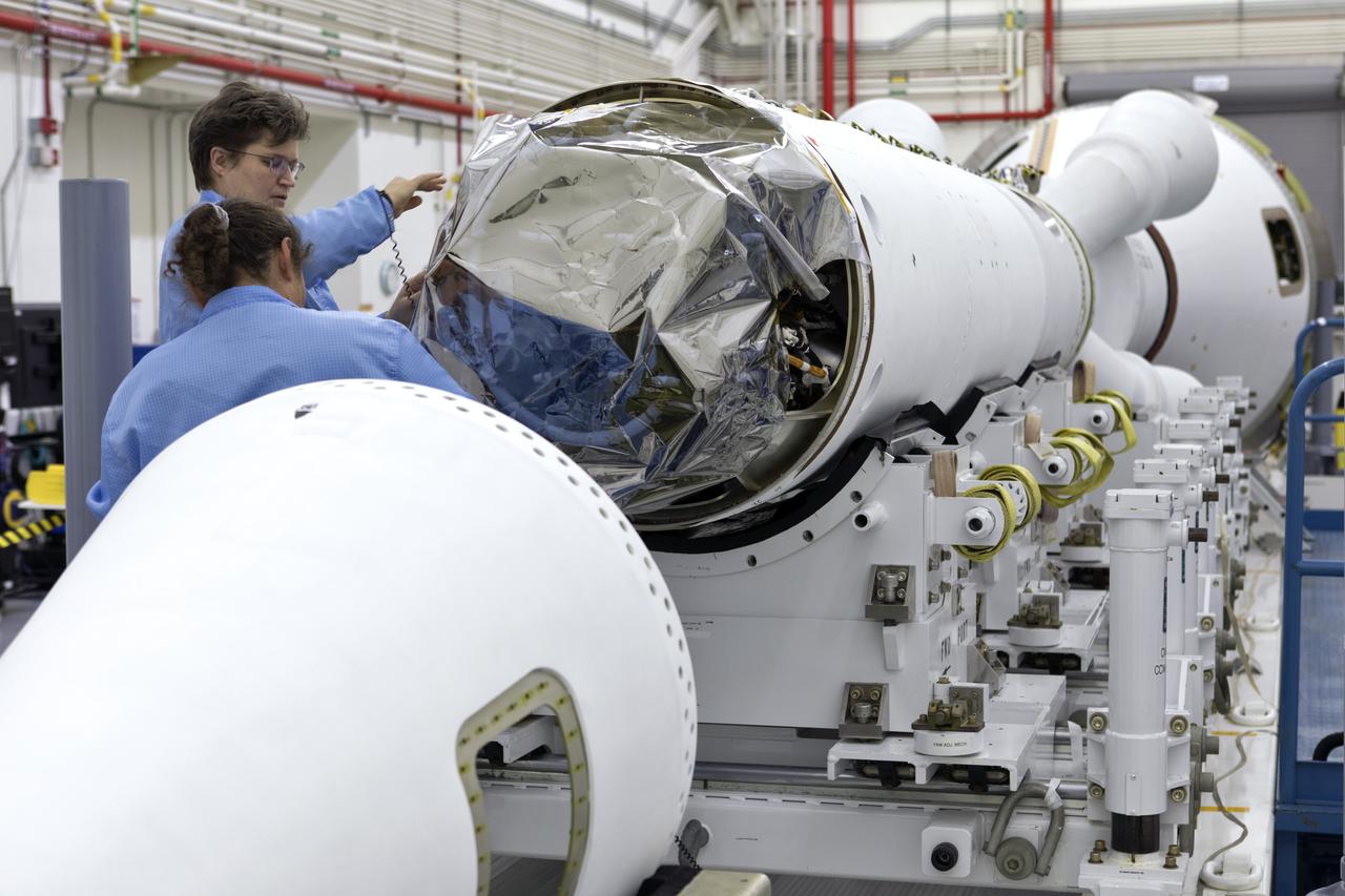
Inside the Launch Abort System Facility (LASF) at NASA’s Kennedy Space Center in Florida, workers assemble the Launch Abort System (LAS) on Feb. 5, 2019, that will be used for the Orion Ascent Abort-2 (AA-2) Flight Test. AA-2 is a full-stress test of the LAS, scheduled for Spring 2019. AA-2 will launch from Space Launch Complex 46, carrying a fully functional LAS and a 22,000-pound Orion test vehicle to an altitude of 31,000 feet and traveling at more than 1,000 miles an hour. The test will verify the LAS can steer the crew module and astronauts aboard to safety in the event of an issue with the Space Launch System (SLS) rocket when the spacecraft is under the highest aerodynamic loads it will experience during a rapid climb into space. NASA's Orion and Exploration Ground Systems programs and contractors from Jacob's and Northrop Grumman in conjunction with the Air Force Space and Missile Center's Launch Operations branch are performing flight operations for AA-2.
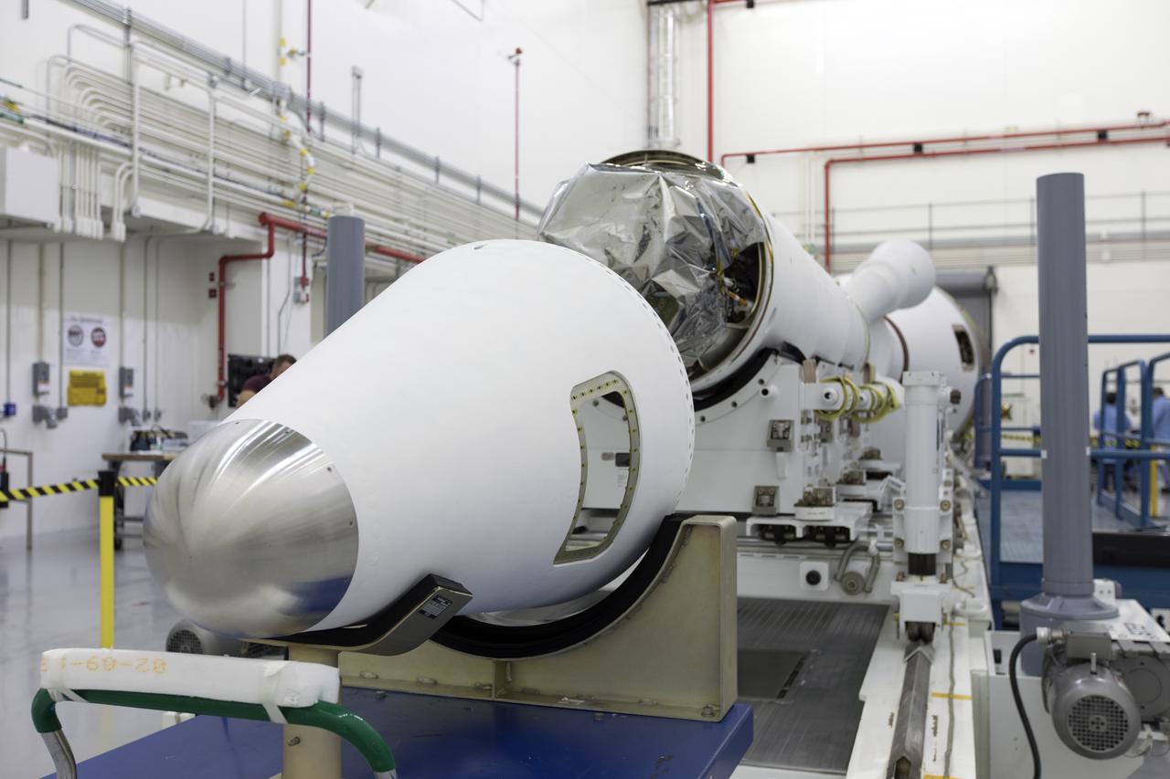
Inside the Launch Abort System Facility (LASF) at NASA’s Kennedy Space Center in Florida, the Launch Abort System (LAS) that will be used for the Orion Ascent Abort-2 (AA-2) Flight Test is being assembled on Feb. 5, 2019. AA-2 is a full-stress test of the LAS, scheduled for Spring 2019. AA-2 will launch from Space Launch Complex 46, carrying a fully functional LAS and a 22,000-pound Orion test vehicle to an altitude of 31,000 feet and traveling at more than 1,000 miles an hour. The test will verify the LAS can steer the crew module and astronauts aboard to safety in the event of an issue with the Space Launch System (SLS) rocket when the spacecraft is under the highest aerodynamic loads it will experience during a rapid climb into space. NASA's Orion and Exploration Ground Systems programs and contractors from Jacob's and Northrop Grumman in conjunction with the Air Force Space and Missile Center's Launch Operations branch are performing flight operations for AA-2.
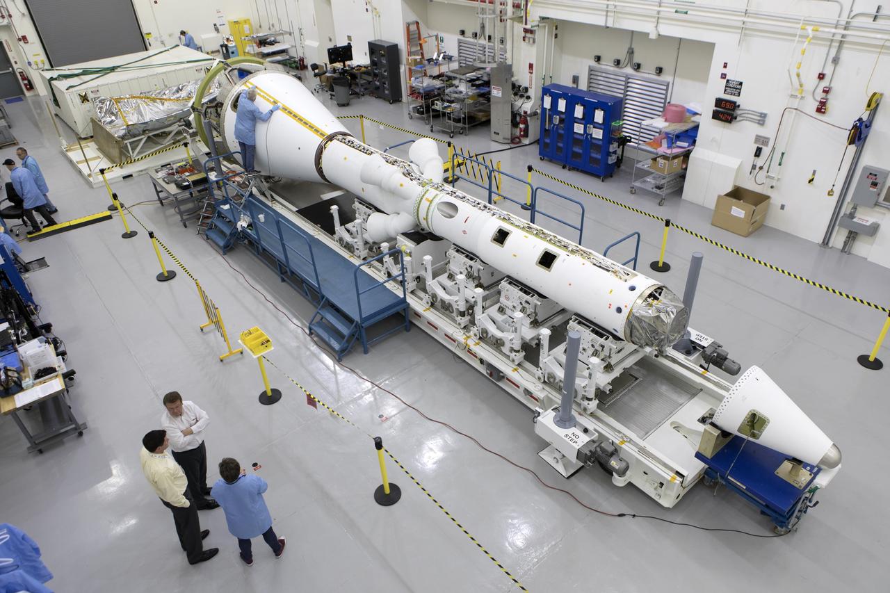
In this view from above inside the Launch Abort System Facility (LASF) at NASA’s Kennedy Space Center in Florida, the Launch Abort System (LAS) that will be used for the Orion Ascent Abort-2 (AA-2) Flight Test is being assembled on Feb. 5, 2019. AA-2 is a full-stress test of the LAS, scheduled for Spring 2019. AA-2 will launch from Space Launch Complex 46, carrying a fully functional LAS and a 22,000-pound Orion test vehicle to an altitude of 31,000 feet and traveling at more than 1,000 miles an hour. The test will verify the LAS can steer the crew module and astronauts aboard to safety in the event of an issue with the Space Launch System (SLS) rocket when the spacecraft is under the highest aerodynamic loads it will experience during a rapid climb into space. NASA's Orion and Exploration Ground Systems programs and contractors from Jacob's and Northrop Grumman in conjunction with the Air Force Space and Missile Center's Launch Operations branch are performing flight operations for AA-2.

KENNEDY SPACE CENTER, FLA. -- The frustum of a forward skirt assembly of a spent solid rocket booster (SRB) from the STS-87 launch on Nov. 19 is transported into the Hangar AF area at Cape Canaveral Air Station. Hangar AF is a building originally used for Project Mercury, the first U.S. manned space program. The SRBs are the largest solid propellant motors ever flown and the first designed for reuse. After a Shuttle is launched, the SRBs are jettisoned at two minutes, seven seconds into the flight. At six minutes and 44 seconds after liftoff, the spent SRBs, weighing about 165,000 lb., have slowed their descent speed to about 62 mph and splashdown takes place in a predetermined area. They are retrieved from the Atlantic Ocean by special recovery vessels and returned for refurbishment and eventual reuse on future Shuttle flights. Once at Hangar AF, the SRBs are unloaded onto a hoisting slip and mobile gantry cranes lift them onto tracked dollies where they are safed and undergo their first washing
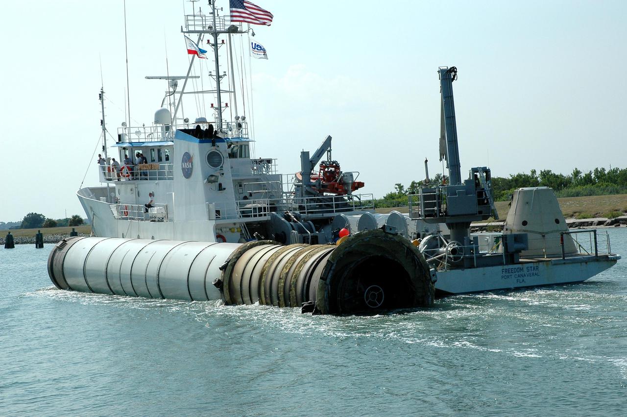
KENNEDY SPACE CENTER, FLA. - Kennedy Space Center employees on the solid rocket booster recovery ship Freedom Star acknowledge photographers awaiting their arrival at Port Canaveral. The ship, with a spent solid rocket booster (SRB) from the STS-114 launch on July 26 in tow, is headed for Hangar AF on Cape Canaveral Air Force Station. The SRBs are the largest solid propellant motors ever flown and the first designed for reuse. After a Shuttle is launched, the SRBs are jettisoned at two minutes, seven seconds into the flight. At six minutes and 44 seconds after liftoff, the spent SRBs, weighing about 165,000 lb., have slowed their descent speed to about 62 mph and splashdown takes place in a predetermined area. They are retrieved from the Atlantic Ocean by special recovery vessels and returned for refurbishment and eventual reuse on future Shuttle flights. Once at Hangar AF, the SRBs are unloaded onto a hoisting slip and mobile gantry cranes lift them onto tracked dollies where they are safed and undergo their first washing.
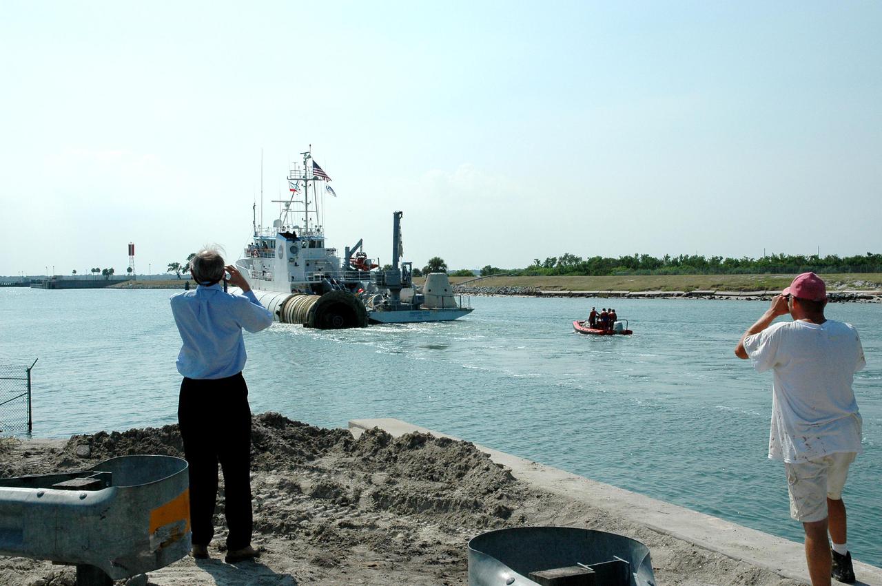
KENNEDY SPACE CENTER, FLA. - Photographers capture the solid rocket booster recovery ship Freedom Star, with a spent solid rocket booster (SRB) from the STS-114 launch on July 26 in tow, as it makes it way through Port Canaveral to Hangar AF on the Cape Canaveral Air Force Station. The SRBs are the largest solid propellant motors ever flown and the first designed for reuse. After a Shuttle is launched, the SRBs are jettisoned at two minutes, seven seconds into the flight. At six minutes and 44 seconds after liftoff, the spent SRBs, weighing about 165,000 lb., have slowed their descent speed to about 62 mph and splashdown takes place in a predetermined area. They are retrieved from the Atlantic Ocean by special recovery vessels and returned for refurbishment and eventual reuse on future Shuttle flights. Once at Hangar AF, the SRBs are unloaded onto a hoisting slip and mobile gantry cranes lift them onto tracked dollies where they are safed and undergo their first washing.