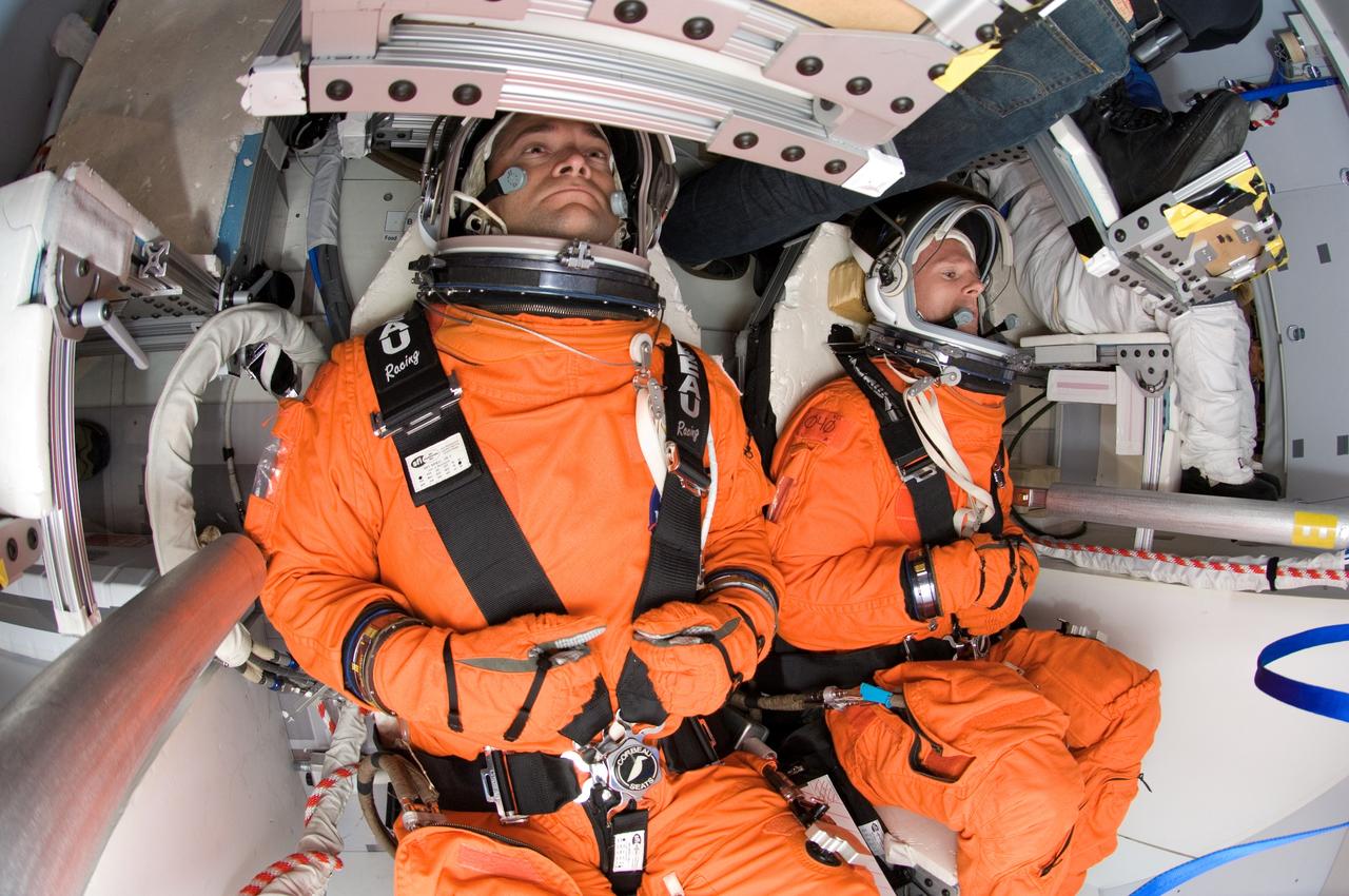
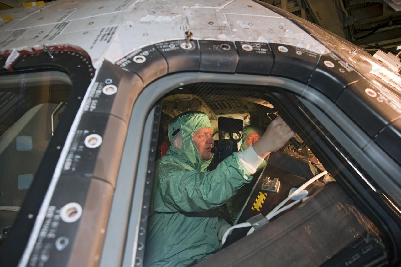
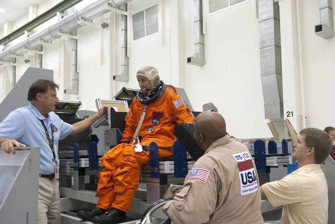
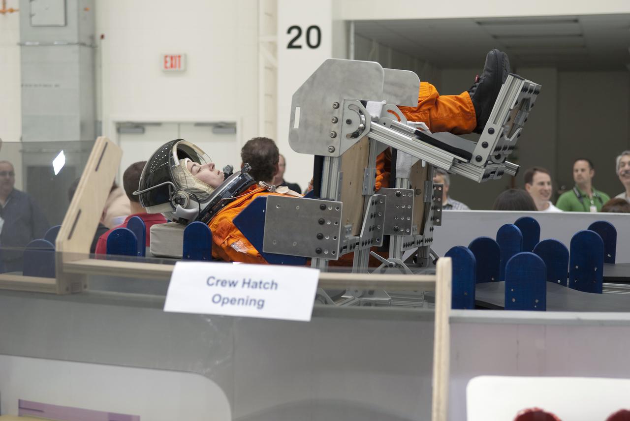
Photographic documentation of the CEV Seat Layout Evaluation taken in the Orion mockup located in bldg 9NW, Johnson Space Center (JSC). Test subjects in orange Launch and Entry Suit (LES) is visible in the seat.
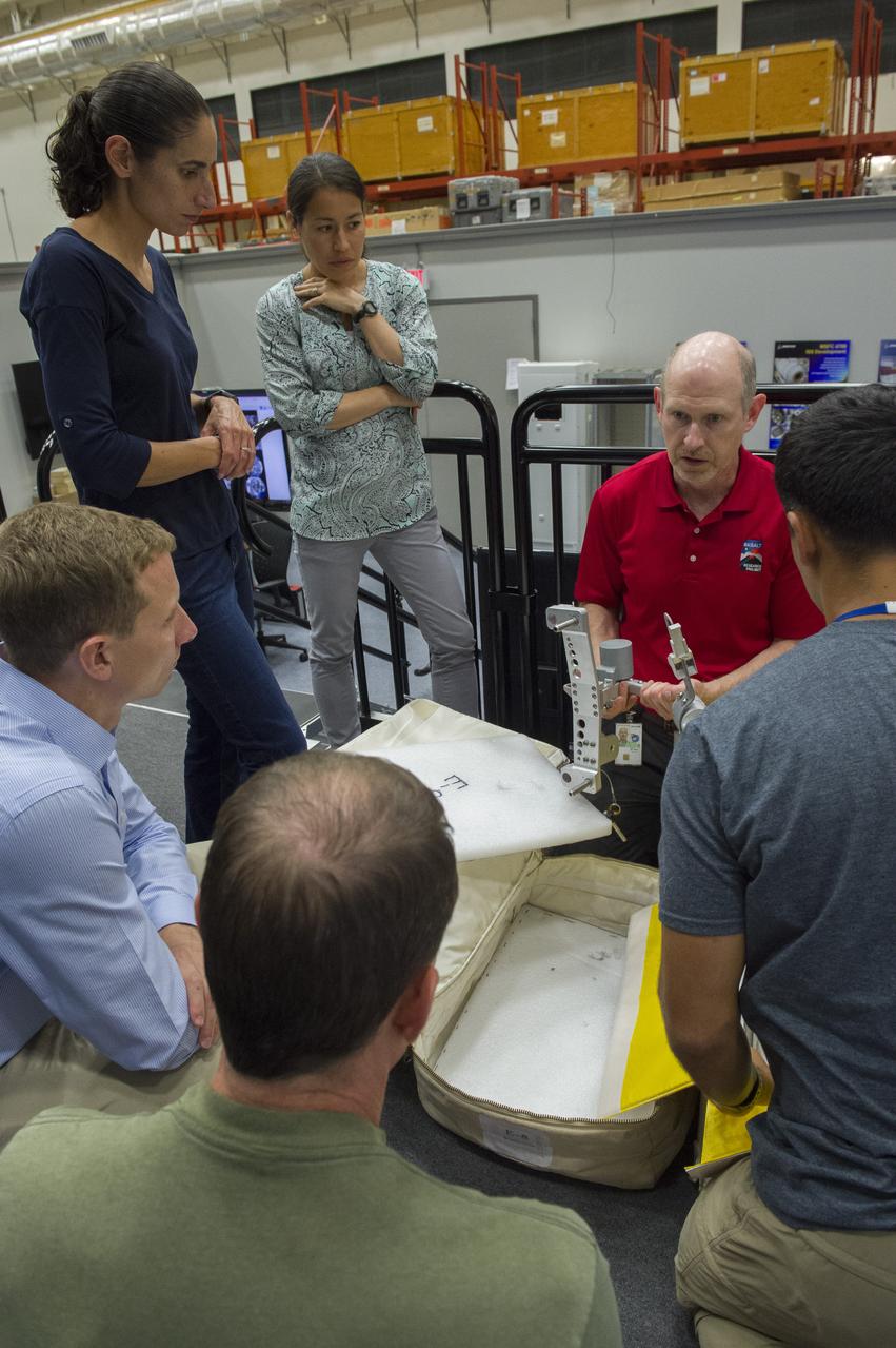
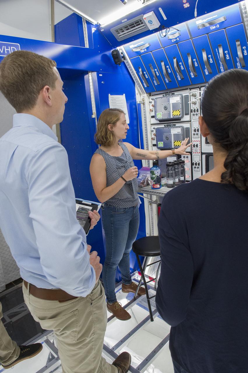
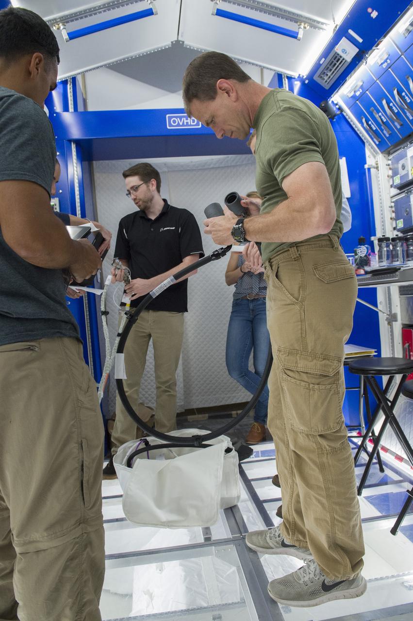
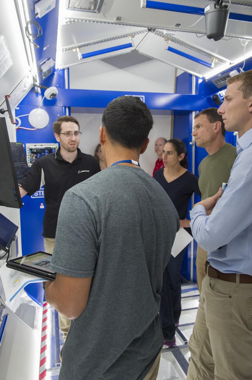
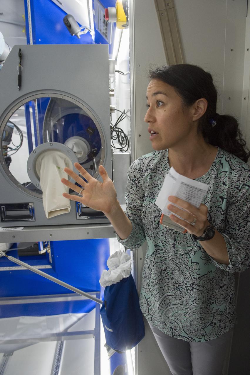
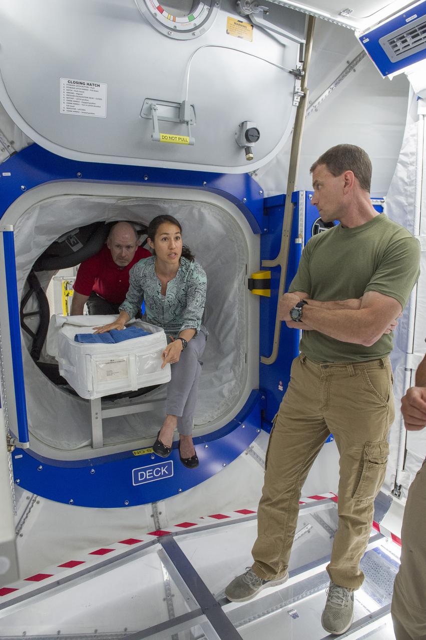
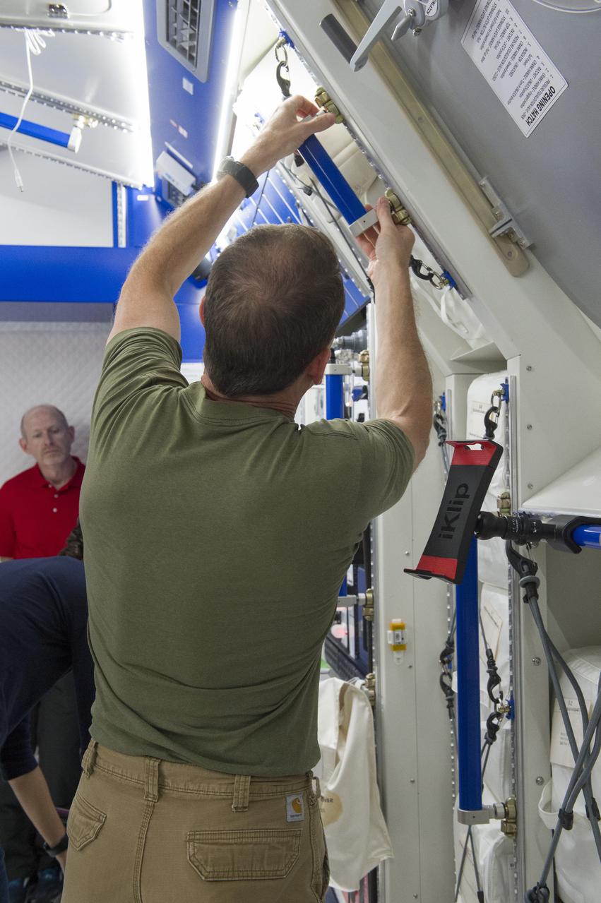
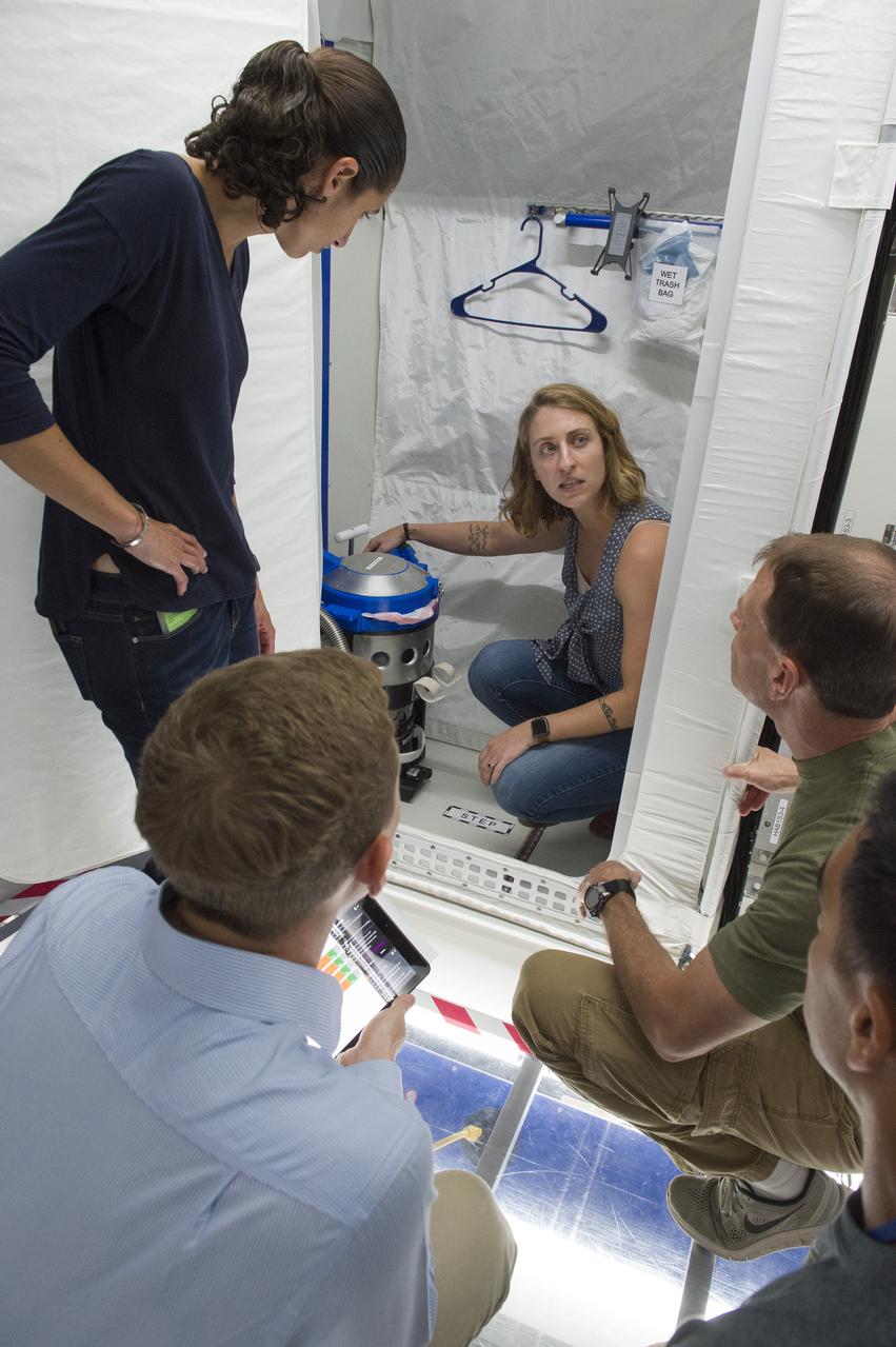
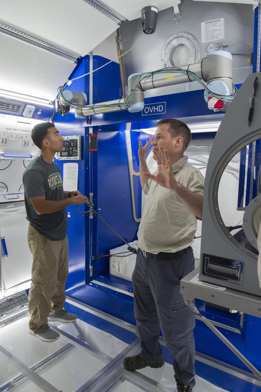
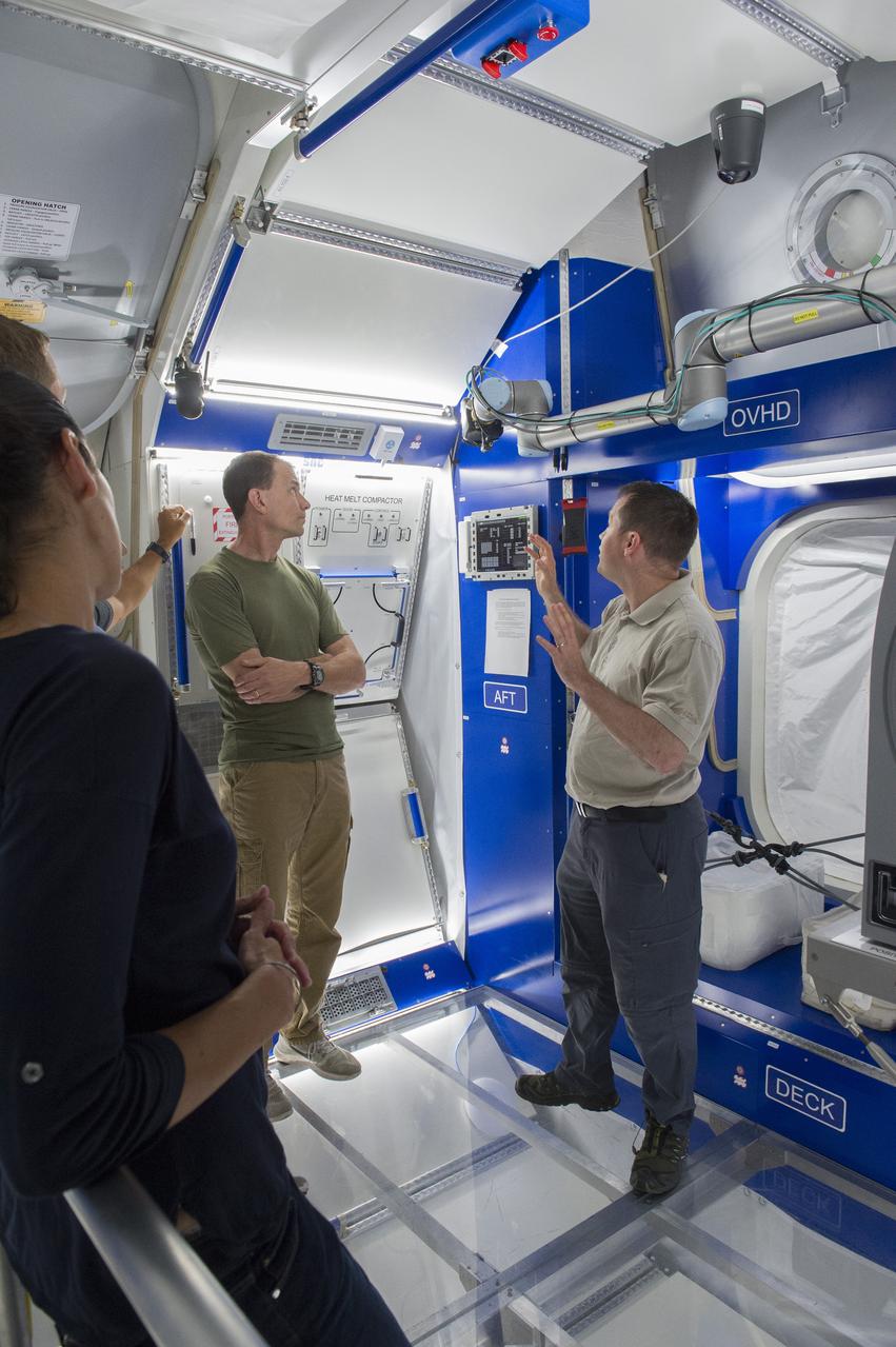
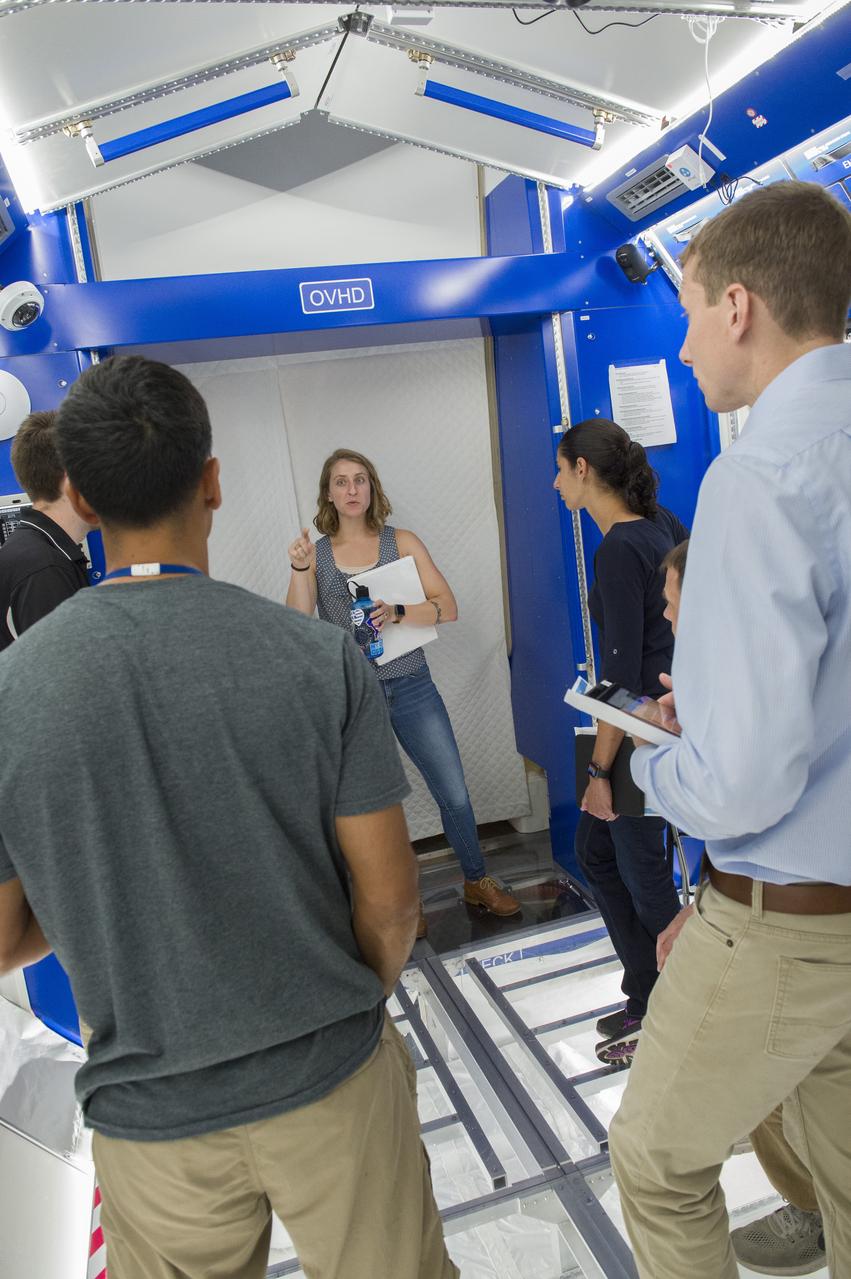
Boeing trainers conduct simulations inside the Boeing Exploration Habitat Demonstrator with astronauts to evaluate the internal layout and ergonomics, to support efficient work-life balance aboard a deep space ship.
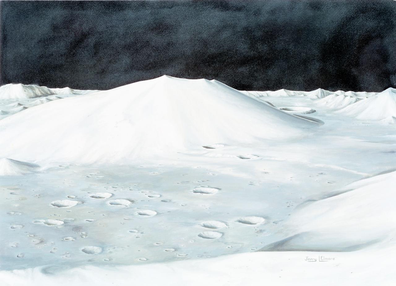
S72-49761 (October 1972) --- An artist's concept illustrating the topographical layout of the Taurus-Littrow landing site of the Apollo 17 lunar landing mission. The Lunar Module touchdown point is in the center of the smooth area in the middle of the picture. The imposing mountain in the center is South Massif. A portion of North Massif is in the lower right corner of the photograph. Note the ridge-like feature extending from South Massif to North Massif. The southern portion of the ridge is called Lee Scarp and the northerly portion Lincoln Scarp. (This concept is by JSC artist Jerry Elmore).
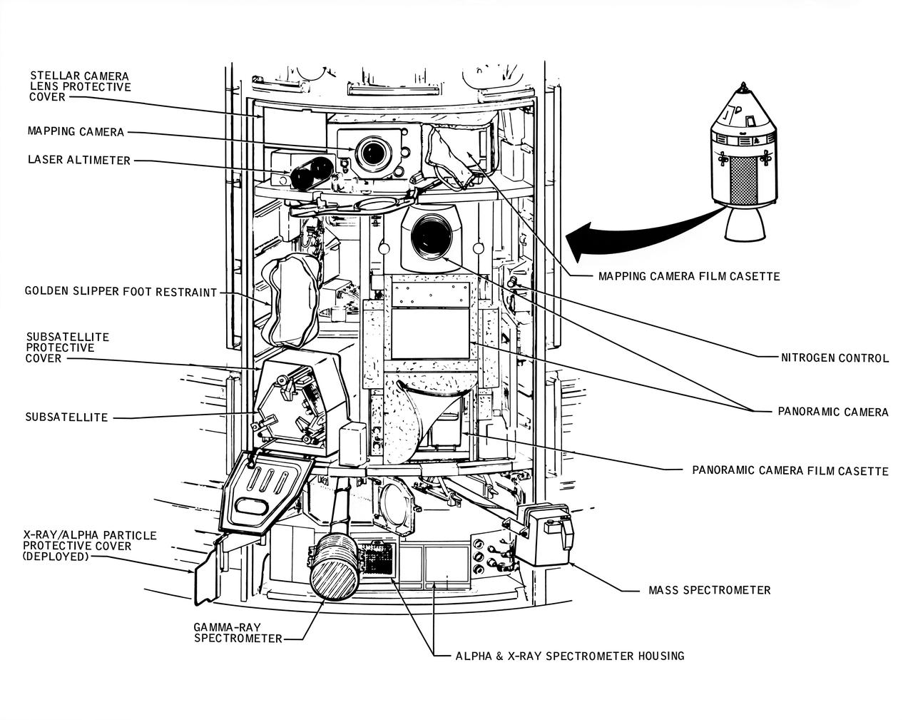
A line drawing illustrating the layout of the Scietific Instrument Module (SIM) of the Apollo 16 Service Module. Shown here is the location in the SIM bay of the equipment for each orbital experiment. Arrows point to various components of the SIM bay. The sensors for the gamma ray spectrometer and the mas spectrometer both extend outward on a boom about 25 feet when the instruments are in use. The subsatellite is launched while the Service Module is in orbit around the moon. The film cassettes must be retrieved prior to Command Module/Service Module separation.
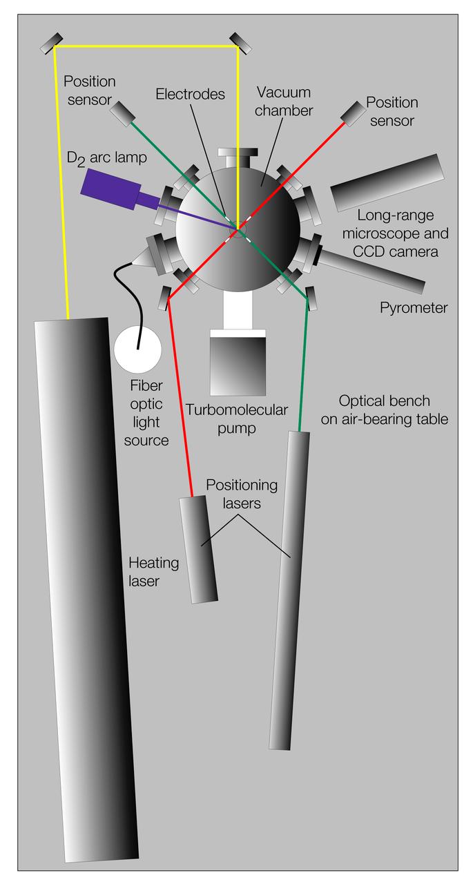
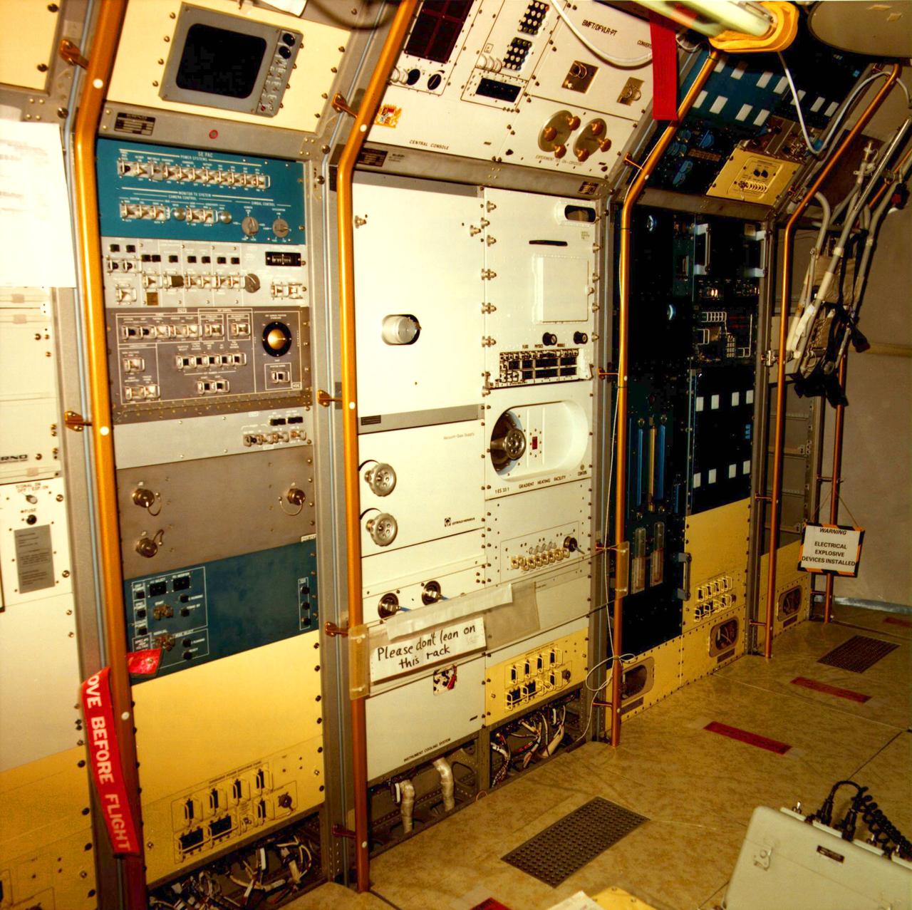
General oayout of Electrostatic Levitator (ESL). The ESL uses static electricity to suspend an object (about 2-3 mm in diameter) inside a vacuum chamber while a laser heats the sample until it melts. This lets scientists record a wide range of physical properties without the sample contacting the container or any instruments, conditions that would alter the readings. The Electrostatic Levitator is one of several tools used in NASA's microgravity materials science program.
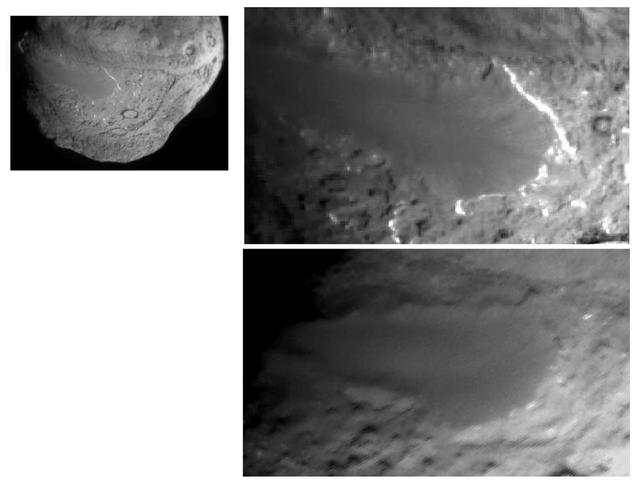
This image layout depicts changes in the surface of comet Tempel 1, observed first by NASA Deep Impact Mission in 2005 top right and again by NASA Stardust-NExT mission on Feb. 14, 2011 bottom right.
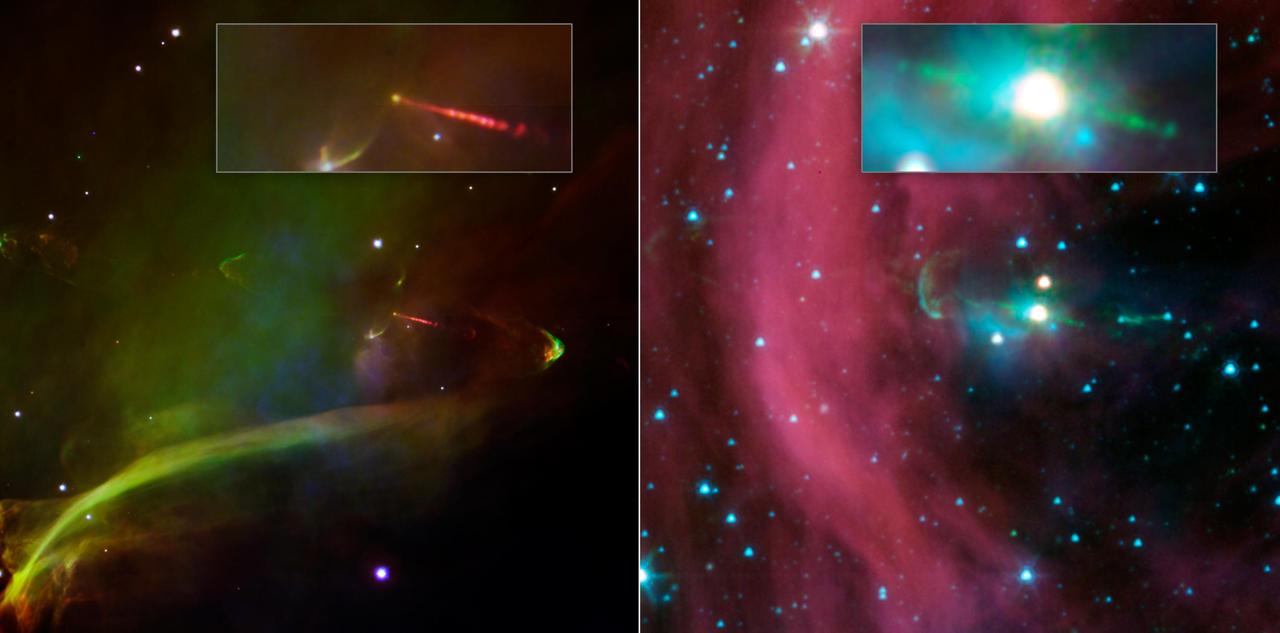
This image layout shows two views of the same baby star from NASA Spitzer Space Telescope. Spitzer view shows that this star has a second, identical jet shooting off in the opposite direction of the first.
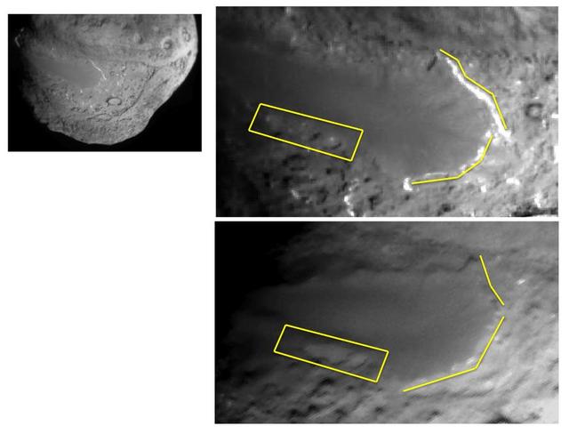
This image layout depicts changes in the surface of comet Tempel 1, observed first by NASA Deep Impact Mission in 2005 top right and again by NASA Stardust-NExT mission on Feb. 14, 2011 bottom right.

DeHavilland QSRA (Quite Short Haul Research Aircraft) cockpit layout drawing
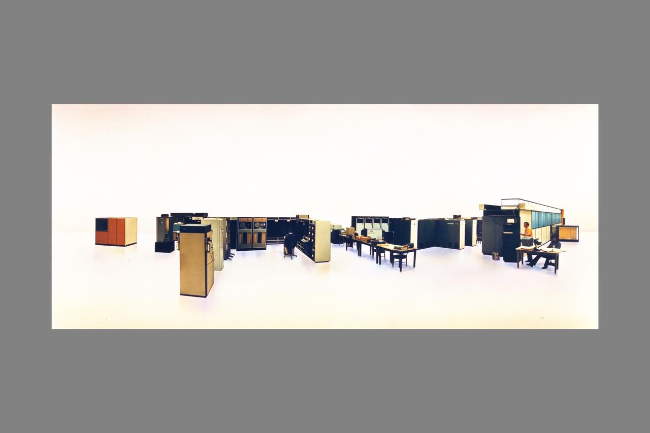
ILLIAC IV computer system layout bldg N-233
Interior view of Spacelab 1 to show layout of equipment and astronauts testing tools. Operations Checkout (O C) Building located at KSC.
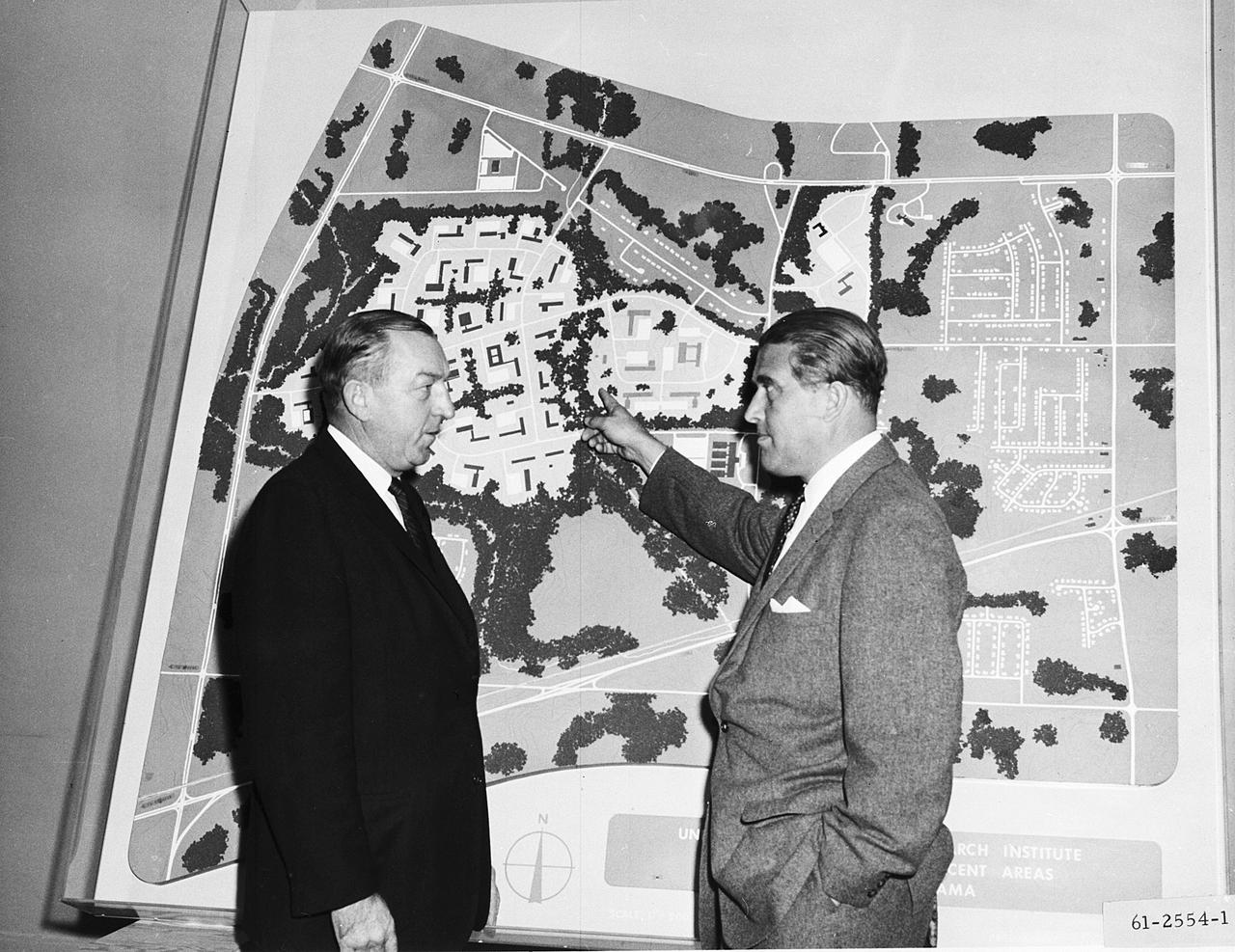
This 1961 photograph shows Dr. von Braun and Alabama Congressman Robert Jones before a huge map illustrating the layout for a Research Institute at the University of Alabama in Huntsville.
Boeing trainers conduct simulations inside the Boeing Exploration Habitat Demonstrator with astronauts to evaluate the internal layout and ergonomics, to support efficient work-life balance aboard a deep space ship.
Boeing trainers conduct simulations inside the Boeing Exploration Habitat Demonstrator with astronauts to evaluate the internal layout and ergonomics, to support efficient work-life balance aboard a deep space ship.
Boeing trainers conduct simulations inside the Boeing Exploration Habitat Demonstrator with astronauts to evaluate the internal layout and ergonomics, to support efficient work-life balance aboard a deep space ship.
Boeing trainers conduct simulations inside the Boeing Exploration Habitat Demonstrator with astronauts to evaluate the internal layout and ergonomics, to support efficient work-life balance aboard a deep space ship.
Boeing trainers conduct simulations inside the Boeing Exploration Habitat Demonstrator with astronauts to evaluate the internal layout and ergonomics, to support efficient work-life balance aboard a deep space ship.
Boeing trainers conduct simulations inside the Boeing Exploration Habitat Demonstrator with astronauts to evaluate the internal layout and ergonomics, to support efficient work-life balance aboard a deep space ship.
Boeing trainers conduct simulations inside the Boeing Exploration Habitat Demonstrator with astronauts to evaluate the internal layout and ergonomics, to support efficient work-life balance aboard a deep space ship.
Boeing trainers conduct simulations inside the Boeing Exploration Habitat Demonstrator with astronauts to evaluate the internal layout and ergonomics, to support efficient work-life balance aboard a deep space ship.
Boeing trainers conduct simulations inside the Boeing Exploration Habitat Demonstrator with astronauts to evaluate the internal layout and ergonomics, to support efficient work-life balance aboard a deep space ship.
Boeing trainers conduct simulations inside the Boeing Exploration Habitat Demonstrator with astronauts to evaluate the internal layout and ergonomics, to support efficient work-life balance aboard a deep space ship.
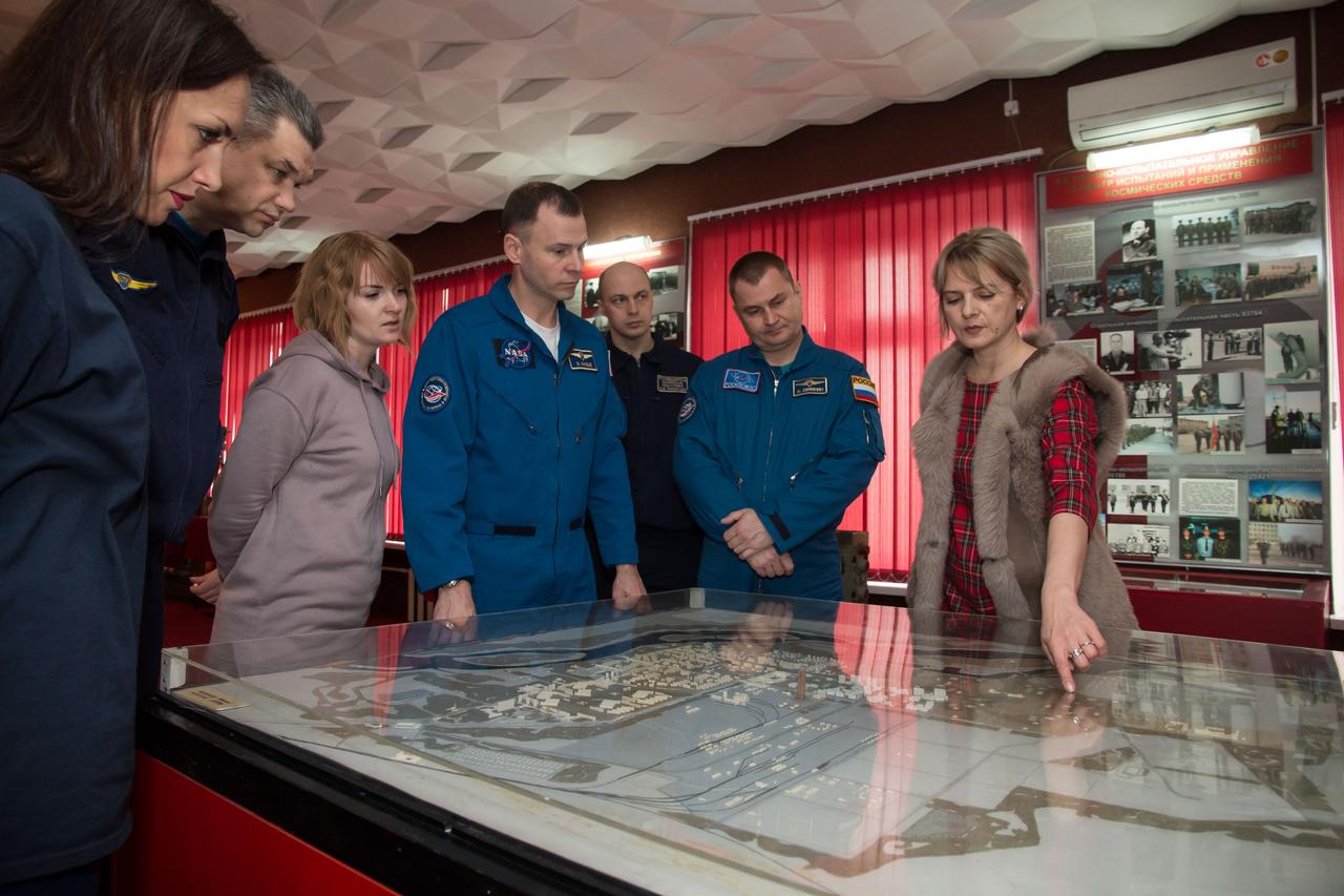
In the city of Baikonur, Kazakhstan, Expedition 55 backup crewmembers Nick Hague of NASA (fourth from left) and Alexey Ovchinin of Roscosmos receive a briefing on the layout of the Baikonur Cosmodrome March 6 during a traditional tour of the city’s museu
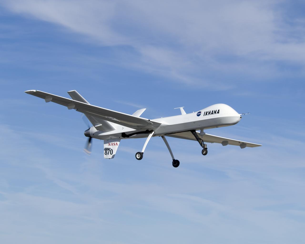
Narrow wings, a Y-tail and rear engine layout distinguish NASA's Ikhana science aircraft, a civil variant of General Atomics' Predator B unmanned aircraft system.
Boeing trainers conduct simulations inside the Boeing Exploration Habitat Demonstrator with astronauts to evaluate the internal layout and ergonomics, to support efficient work-life balance aboard a deep space ship.
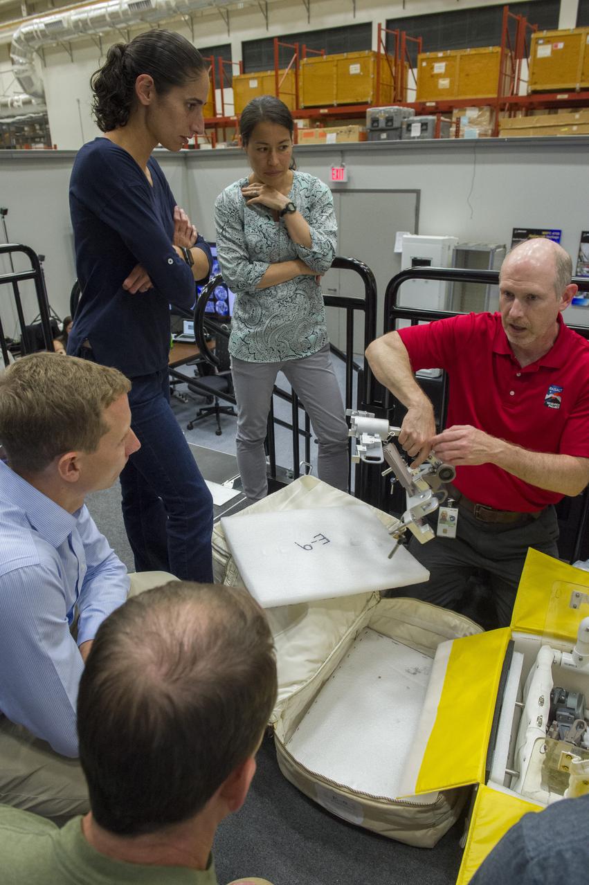
Boeing trainers conduct simulations inside the Boeing Exploration Habitat Demonstrator with astronauts to evaluate the internal layout and ergonomics, to support efficient work-life balance aboard a deep space ship.
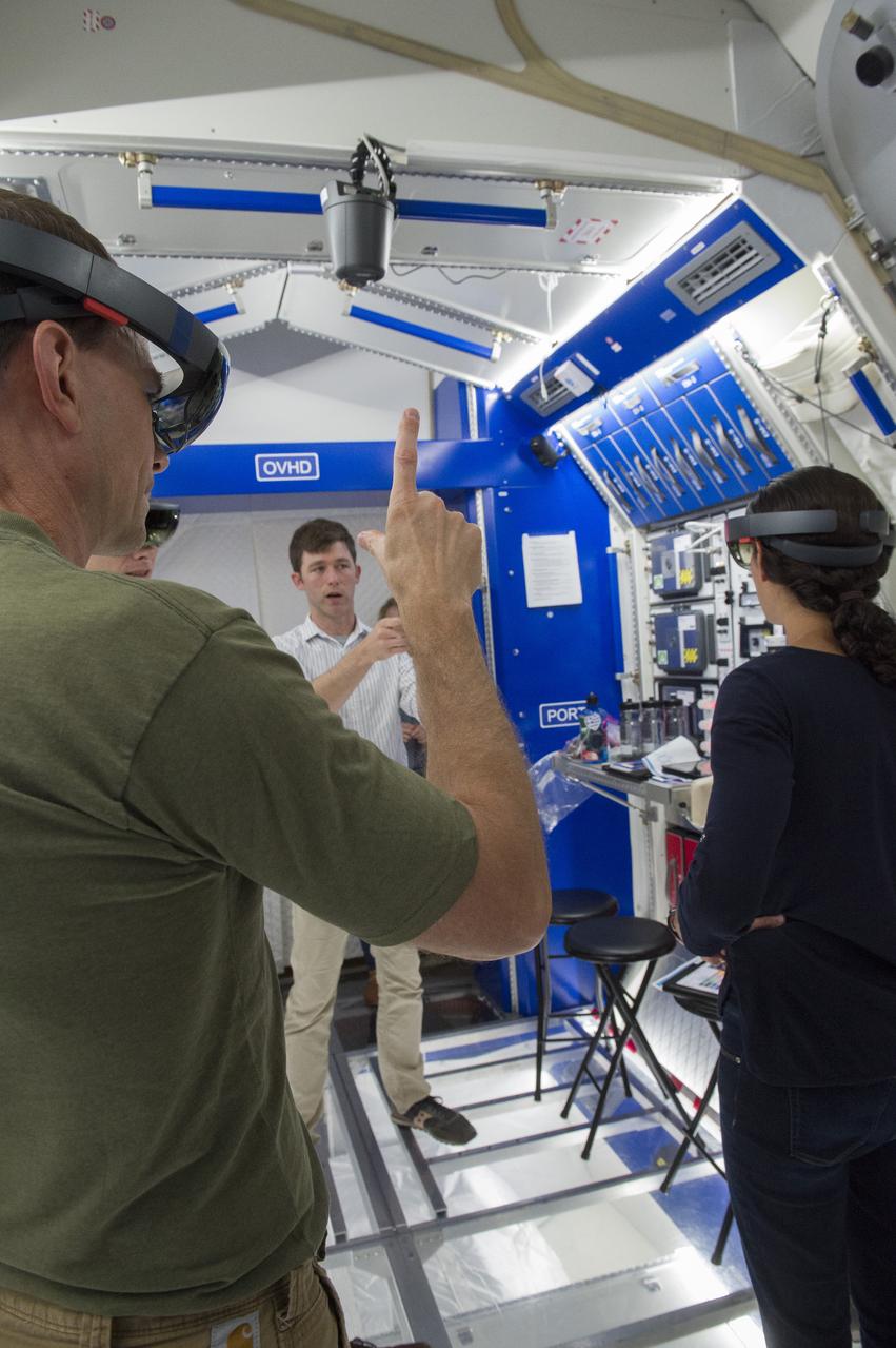
Boeing trainers conduct simulations inside the Boeing Exploration Habitat Demonstrator with astronauts to evaluate the internal layout and ergonomics, to support efficient work-life balance aboard a deep space ship.
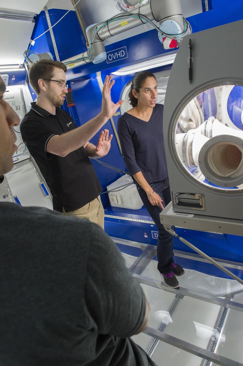
Boeing trainers conduct simulations inside the Boeing Exploration Habitat Demonstrator with astronauts to evaluate the internal layout and ergonomics, to support efficient work-life balance aboard a deep space ship.
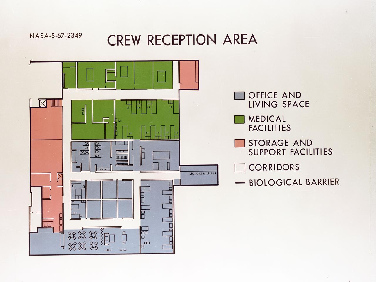
Artist's concept depicting the floor plan of the Crew Reception Area of the Lunar Receiving Laboratory (LRL), bldg 37.

CAPE CANAVERAL, Fla. – An artist's concept shows a possible layout of a commercial spacecraft and rocket using facilities at Launch Pad 39A as NASA's Kennedy Space Center in Florida undergoes a transformation into a multi-user spaceport. Several companies are designing rockets and spacecraft that could be used to launch astronauts and payloads into space in the future. Credit: NASA
Engineering mockup shows the general arrangement of the plarned Biotechnology Facility inside an EXPRESS rack aboard the International Space Station. This layout includes a gas supply module (bottom left), control computer and laptop interface (bottom right), two rotating wall vessels (top right), and support systems.

The main gate (Gate 7) of the Michoud Assembly Facility has been demolished and replaced following the tornado that struck the area in February 2017. The project included moving the gate to a position of 300 feet off the property line (away from Old Gentilly Blvd). The configuration included expanding the entrance to the gate from 2 lanes to 3 while maintaining 2 exit lanes. This layout provides for a guard post shelter rain canopy over two of the entrance lanes. Assessments and repairs continue on various structures and facilities across the facility.

The main gate (Gate 7) of the Michoud Assembly Facility has been demolished and replaced following the tornado that struck the area in February 2017. The project included moving the gate to a position of 300 feet off the property line (away from Old Gentilly Blvd). The configuration included expanding the entrance to the gate from 2 lanes to 3 while maintaining 2 exit lanes. This layout provides for a guard post shelter rain canopy over two of the entrance lanes. Assessments and repairs continue on various structures and facilities across the facility.
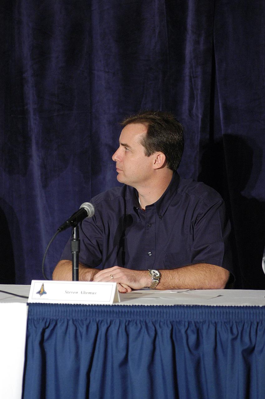
KENNEDY SPACE CENTER, FLA. - Steve Altemus, shuttle test director at KSC, provides expert information to the Columbia Accident Investigation Board. Over the course of two days, the Board's chairman, retired Navy Admiral Harold W. "Hal" Gehman Jr., and other board members have been hearing from experts discussing the role of the Kennedy Space Center in the Shuttle Program, Shuttle Safety and Debris Collection, Layout and Analysis and Forensic Metallurgy.
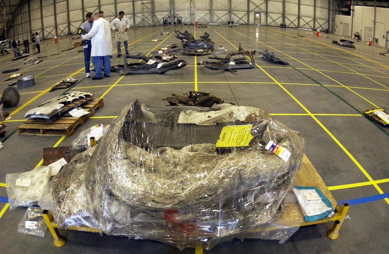
The layout of the debris from the Space Shuttle Columbia is captured in this wide-angle view of a section of the RLV Hangar floor. The debris is being shipped to KSC from the collection point at Barksdale Air Force Base, Shreveport, La. As part of the ongoing investigation into the tragic accident that claimed Columbia and her crew of seven, workers will attempt to reconstruct the orbiter inside the hangar.
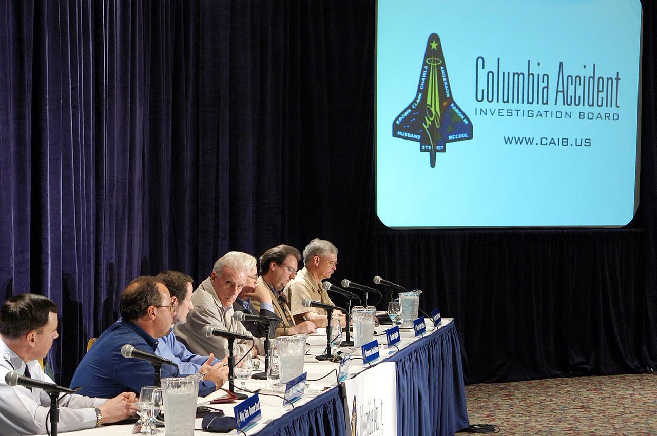
KENNEDY SPACE CENTER, FLA. - The Columbia Accident Investigation Board gathers for its third public hearing, held in Cape Canaveral, Fla. Over the course of two days, the Board's chairman, retired Navy Admiral Harold W. "Hal" Gehman Jr., and other board members would hear from experts discussing the role of the Kennedy Space Center in the Shuttle Program, Shuttle Safety and Debris Collection, Layout and Analysis and Forensic Metallurgy.
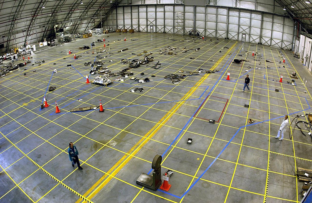
KENNEDY SPACE CENTER, FLA. -- The layout of the debris from the Space Shuttle Columbia received at KSC to date is captured in this aerial view of the RLV Hangar floor. Several shipments of the debris have been delivered to KSC from the collection point at Barksdale Air Force Base, Shreveport, La. As part of the ongoing investigation into the tragic accident that claimed Columbia and her crew of seven, workers will attempt to reconstruct the orbiter inside the hangar.
Navy Santa Cruz 'Airport'. Airport looking west: Municipal Rating: Location; 6 miles east of city- Altitude; 75ft - Layout: L-shaped, hard smooth dirt, Drainage; natural. East-west 2,500' X 300' North-South 2,000 X 400' to S.E. trees, to N.E. Hangar and Aviation fuel, Tower: 50' hight - Day Service Only
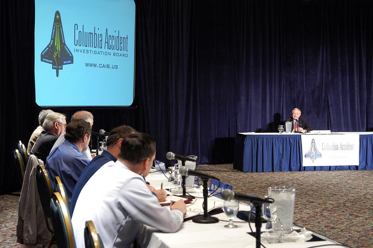
KENNEDY SPACE CENTER, FLA. - The Columbia Accident Investigation Board (left) listens to Center Director Roy Bridges at the third public hearing of the Board, held in Cape Canaveral, Fla. Over the course of two days, the Board's chairman, retired Navy Admiral Harold W. "Hal" Gehman Jr., and other board members would hear from experts discussing the role of the Kennedy Space Center in the Shuttle Program, Shuttle Safety and Debris Collection, Layout and Analysis and Forensic Metallurgy.
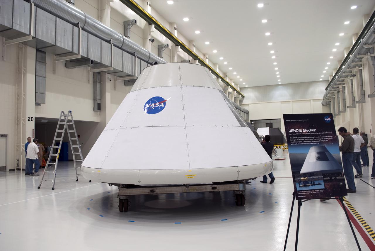
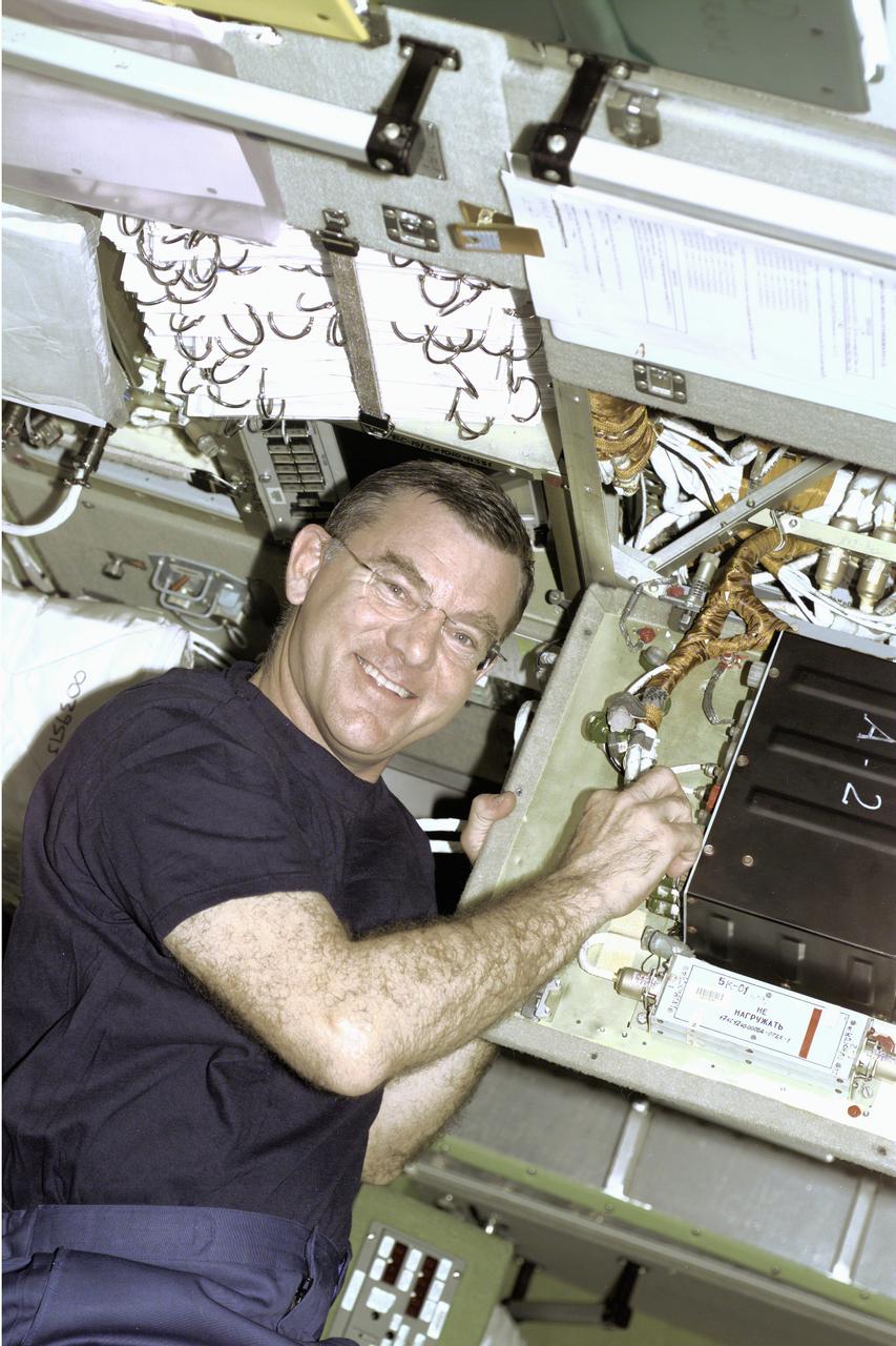
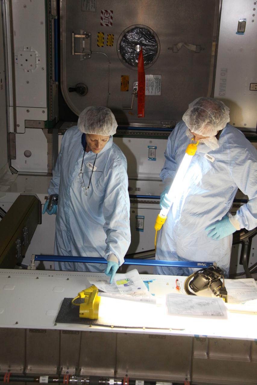
CAPE CANAVERAL, Fla. – In the Operations and Checkout Building at NASA's Kennedy Space Center in Florida, Joint Extravehicular NBL ORION Mockup, or JENOM, is on display. The mock-up details the interior components of the vehicle including seat layout and the subsystem components on the outside of the pressure vessel. Orion mock-ups also have been used to verify accessibility of the servicing locations at the launch pad and in the Vehicle Assembly Building. For information on the development of the Orion capsule, visit www.nasa.gov_orion. Photo credit: NASA_Jim Grossmann
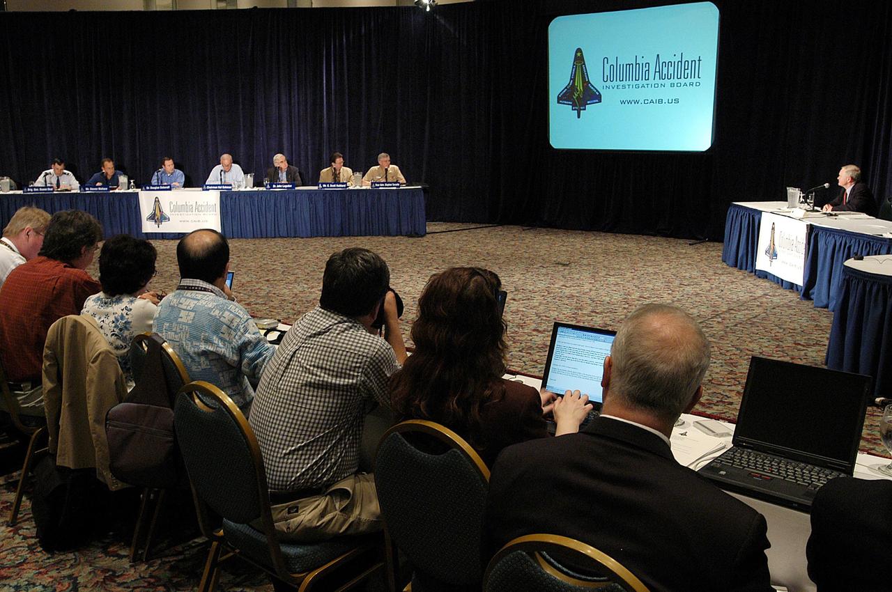
KENNEDY SPACE CENTER, FLA. - At the third public hearing of the Columbia Accident Investigation Board, held in Cape Canaveral, Fla., reporters listen intently to Center Director Roy Bridges (background, right). Board members are in the background, left. Over the course of two days, the Board's chairman, retired Navy Admiral Harold W. "Hal" Gehman Jr., and other board members would hear from experts discussing the role of the Kennedy Space Center in the Shuttle Program, Shuttle Safety and Debris Collection, Layout and Analysis and Forensic Metallurgy.
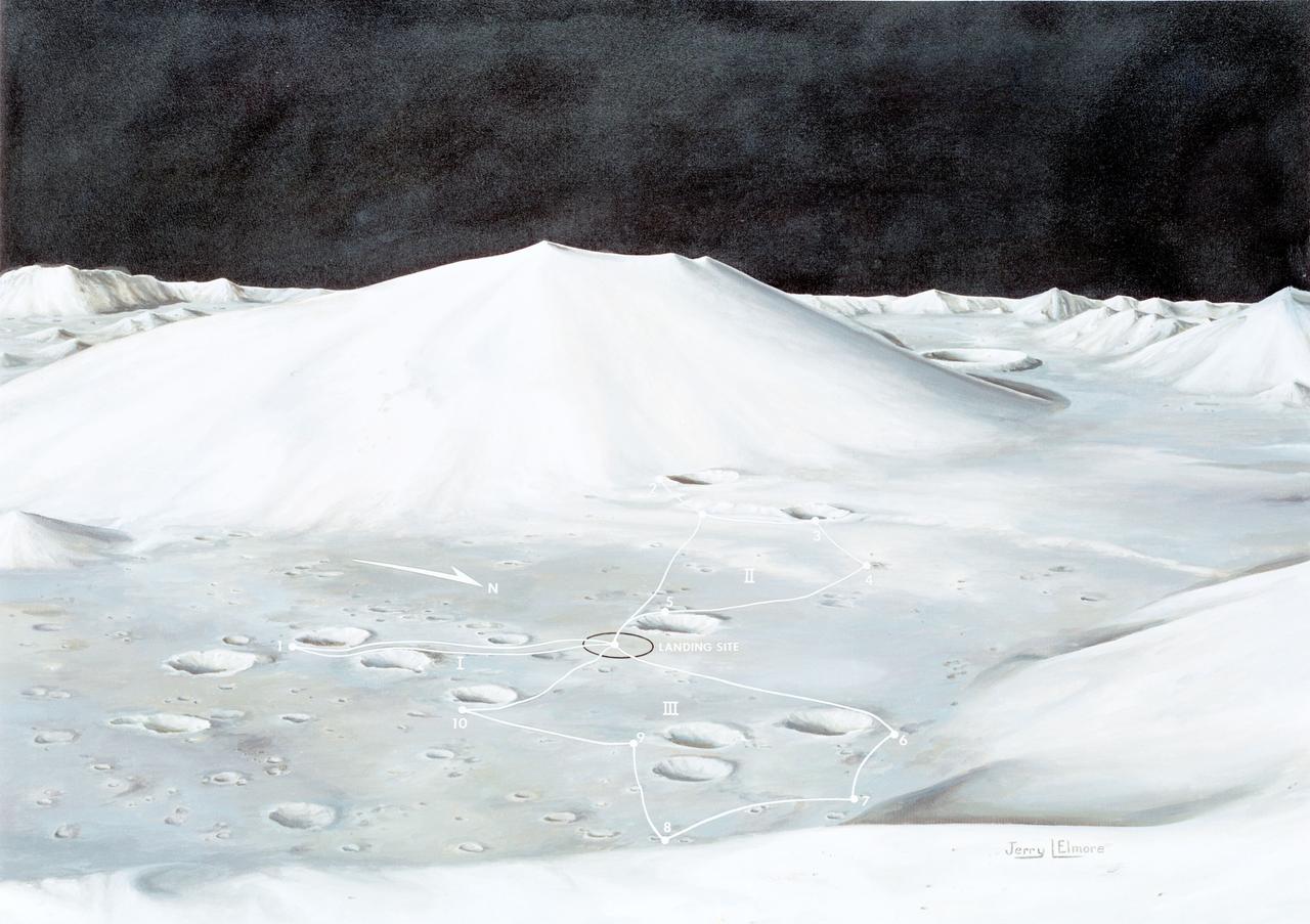
S72-49760 (October 1972) --- An artist's concept illustrating the topographical layout of the Taurus-Littrow landing site of the Apollo 17 lunar landing mission. The Lunar Module touchdown point is in the center of the smooth area in the middle of the picture. The imposing mountain in the center is South Massif. A portion of North Massif is in the lower right corner of the photograph. Note the ridge-like feature extending from South Massif to North Massif. The southern portion of the ridge is called Lee Scarp and the northerly portion Lincoln Scarp. (This concept is by JSC artist Jerry Elmore).
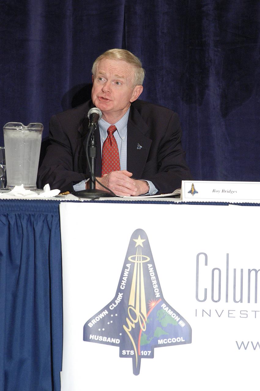
KENNEDY SPACE CENTER, FLA. - Center Director Roy Bridges speaks at a meeting of the Columbia Accident Investigation Board in Cape Canaveral, Fla. Over the course of two days, the Board's chairman, retired Navy Admiral Harold W. "Hal" Gehman Jr., and other board members would hear from experts discussing the role of the Kennedy Space Center in the Shuttle Program, Shuttle Safety and Debris Collection, Layout and Analysis and Forensic Metallurgy.
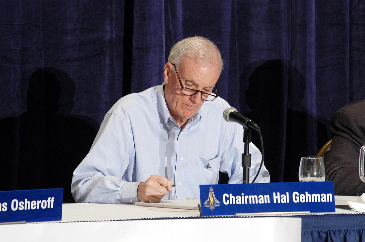
KENNEDY SPACE CENTER, FLA. - Retired Navy Admiral Harold W. "Hal" Gehman Jr., chairman of the Columbia Accident Investigation Board, checks his notes during the third public hearing of the board, held in Cape Canaveral, Fla. Over the course of two days, Gehman and other board members would hear from experts discussing the role of the Kennedy Space Center in the Shuttle Program, Shuttle Safety and Debris Collection, Layout and Analysis and Forensic Metallurgy.
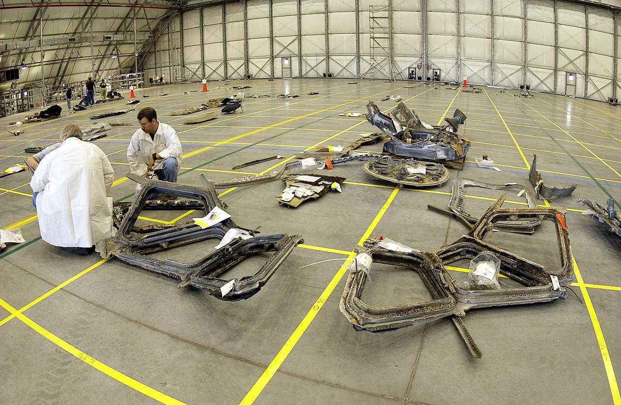
KENNEDY SPACE CENTER, FLA. -- The layout of the debris from the Space Shuttle Columbia is captured in this wide-angle view of a section of the RLV Hangar floor. The debris is being shipped to KSC from the collection point at Barksdale Air Force Base, Shreveport, La. As part of the ongoing investigation into the tragic accident that claimed Columbia and her crew of seven, workers will attempt to reconstruct the orbiter inside the hangar.
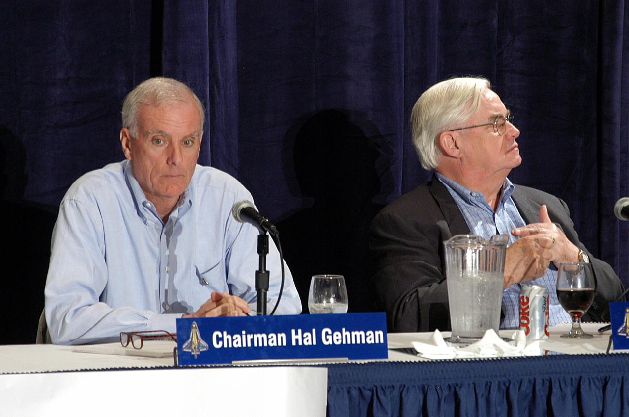
KENNEDY SPACE CENTER, FLA. - Retired Navy Admiral Harold W. "Hal" Gehman Jr., chairman of the Columbia Accident Investigation Board, and board member Dr. John Logsdon, director of the Space Policy Institute, George Washington University, listen to expert information about the role of the Kennedy Space Center in the Shuttle Program, Shuttle Safety and Debris Collection, Layout and Analysis and Forensic Metallurgy. This was the third public hearing of the board, which was held in Cape Canaveral, Fla.
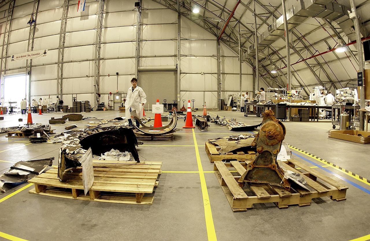
KENNEDY SPACE CENTER, FLA. -- The layout of the debris from the Space Shuttle Columbia is captured in this wide-angle view of a section of the RLV Hangar floor. The debris is being shipped to KSC from the collection point at Barksdale Air Force Base, Shreveport, La. As part of the ongoing investigation into the tragic accident that claimed Columbia and her crew of seven, workers will attempt to reconstruct the orbiter inside the hangar.
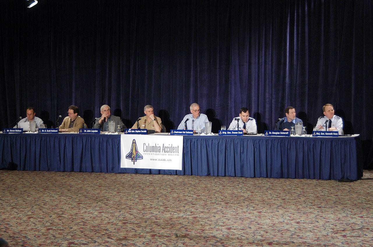
KENNEDY SPACE CENTER, FLA. - The Columbia Accident Investigation Board gathers for a second day for its third public hearing, held in Cape Canaveral, Fla. Over the course of two days, the Board's chairman, retired Navy Admiral Harold W. "Hal" Gehman Jr., and other board members have been hearing from experts discussing the role of the Kennedy Space Center in the Shuttle Program, Shuttle Safety and Debris Collection, Layout and Analysis and Forensic Metallurgy.
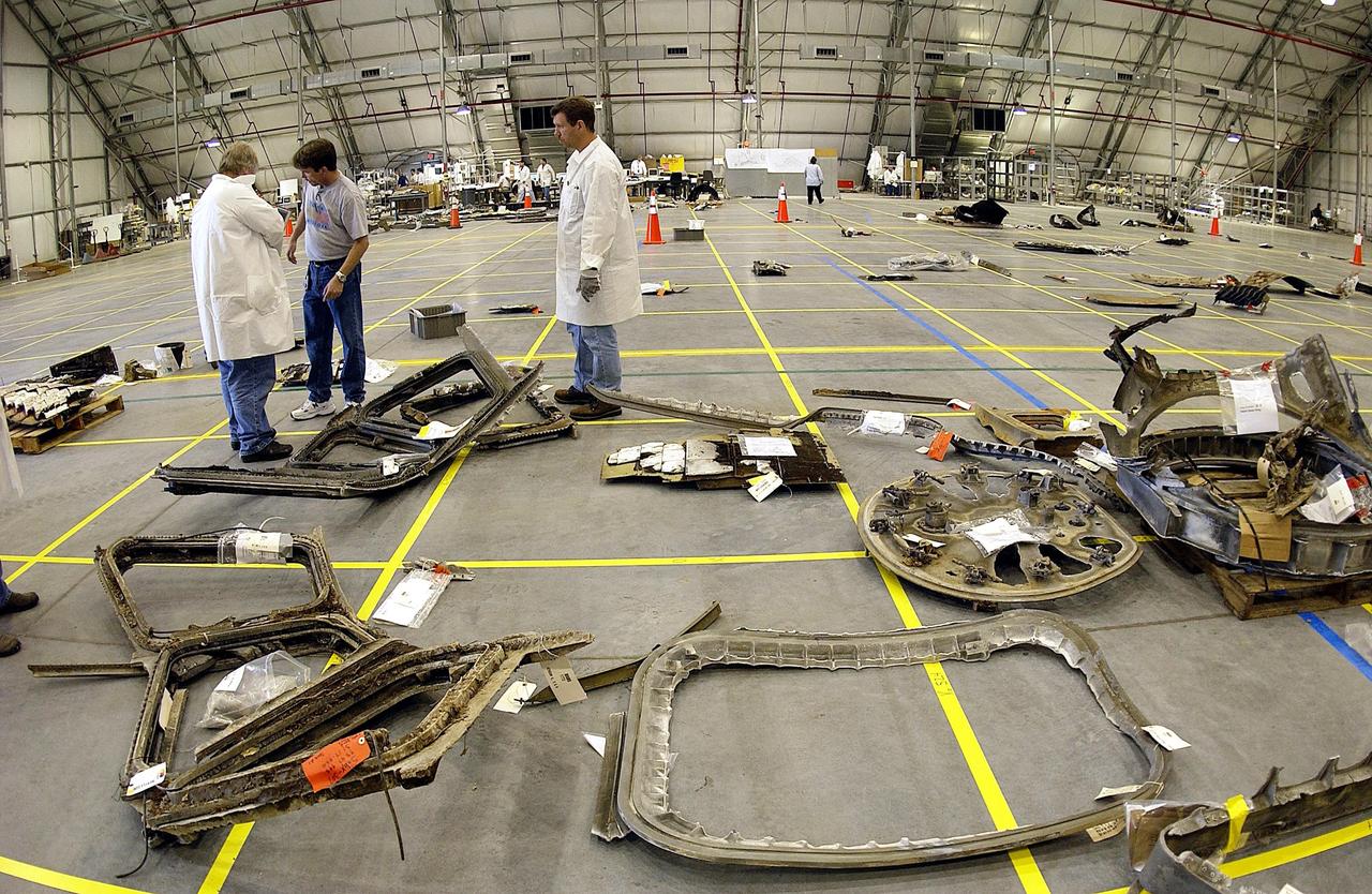
KENNEDY SPACE CENTER, FLA. -- The layout of the debris from the Space Shuttle Columbia is captured in this wide-angle view of a section of the RLV Hangar floor. The debris is being shipped to KSC from the collection point at Barksdale Air Force Base, Shreveport, La. As part of the ongoing investigation into the tragic accident that claimed Columbia and her crew of seven, workers will attempt to reconstruct the orbiter inside the hangar.
CAPE CANAVERAL, Fla. – In the Operations and Checkout Building at NASA's Kennedy Space Center in Florida, a mock-up of the Orion crew exploration vehicle is on display. The mock-up details the interior components of the vehicle including seat layout and the subsystem components on the outside of the pressure vessel. Orion mock-ups also have been used to verify accessibility of the servicing locations at the launch pad and in the Vehicle Assembly Building. For information on the development of the Orion capsule, visit www.nasa.gov_orion. Photo credit: NASA_Jim Grossmann
CAPE CANAVERAL, Fla. – An artist's concept shows a possible layout of a commercial spacecraft and rocket using facilities inside the Vehicle Assembly Building at NASA's Kennedy Space Center in Florida as the center undergoes a transformation into a multi-user spaceport. At left is the Space Launch System, or SLS, currently under development by NASA. At right is a generic rocket and spacecraft design indicative of the likely arrangement of such a vehicle. Several companies are designing rockets and spacecraft that could be used to launch astronauts and payloads into space in the future. Credit: NASA
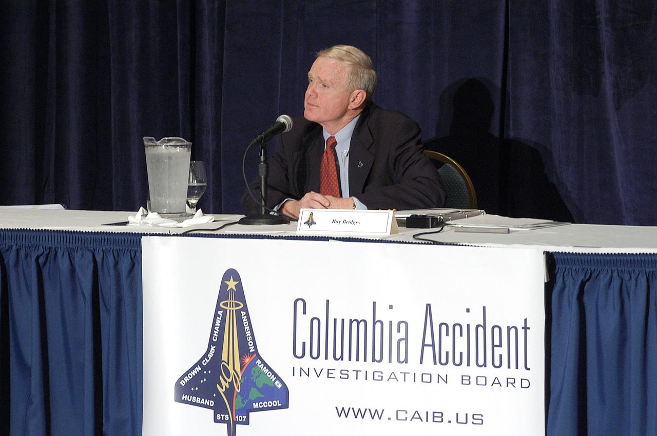
KENNEDY SPACE CENTER, FLA. - Center Director Roy Bridges speaks at a meeting of the Columbia Accident Investigation Board in Cape Canaveral, Fla. Over the course of two days, the Board's chairman, retired Navy Admiral Harold W. "Hal" Gehman Jr., and other board members would hear from experts discussing the role of the Kennedy Space Center in the Shuttle Program, Shuttle Safety and Debris Collection, Layout and Analysis and Forensic Metallurgy.
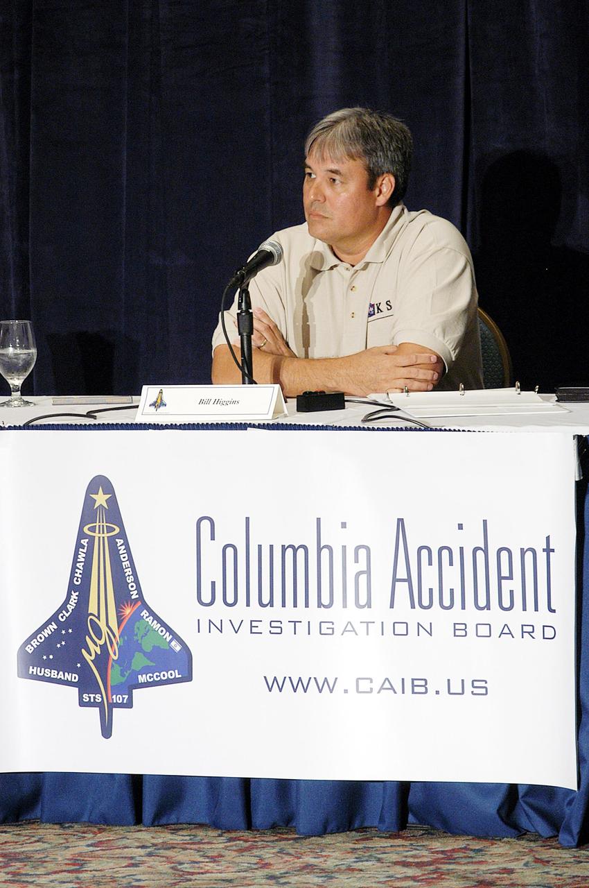
KENNEDY SPACE CENTER, FLA. - William Higgins, chief of Shuttle Processing Safety and Mission Assurance Division at KSC, talks to the Columbia Accident Investigation Board during its third public hearing, held in Cape Canaveral, Fla. Over the course of two days, the Board's chairman, retired Navy Admiral Harold W. "Hal" Gehman Jr., and other board members would hear from experts discussing the role of the Kennedy Space Center in the Shuttle Program, Shuttle Safety and Debris Collection, Layout and Analysis and Forensic Metallurgy.
CAPE CANAVERAL, Fla. – In the Operations and Checkout Building at NASA's Kennedy Space Center in Florida, employees peruse exhibits surrounding a mock-up of the Orion crew exploration vehicle. The mock-up details the interior components of the vehicle including seat layout and the subsystem components on the outside of the pressure vessel. Orion mock-ups also have been used to verify accessibility of the servicing locations at the launch pad and in the Vehicle Assembly Building. For information on the development of the Orion capsule, visit www.nasa.gov_orion. Photo credit: NASA_Jim Grossmann
CAPE CANAVERAL, Fla. -- In Orbiter Processing Facility-3 at NASA's Kennedy Space Center in Florida, STS-133 Commander Steve Lindsey familiarizes himself with the layout of the shuttle's cockpit. The astronauts are at Kennedy for the Crew Equipment Interface Test, or CEIT, which provides the crew with hands-on training and observation of shuttle and flight hardware for their mission to the International Space Station. Launch of the STS-133 mission on space shuttle Discovery is targeted for Nov. 1 at 4:33 p.m. EDT. Photo credit: NASA_Kim Shiflett
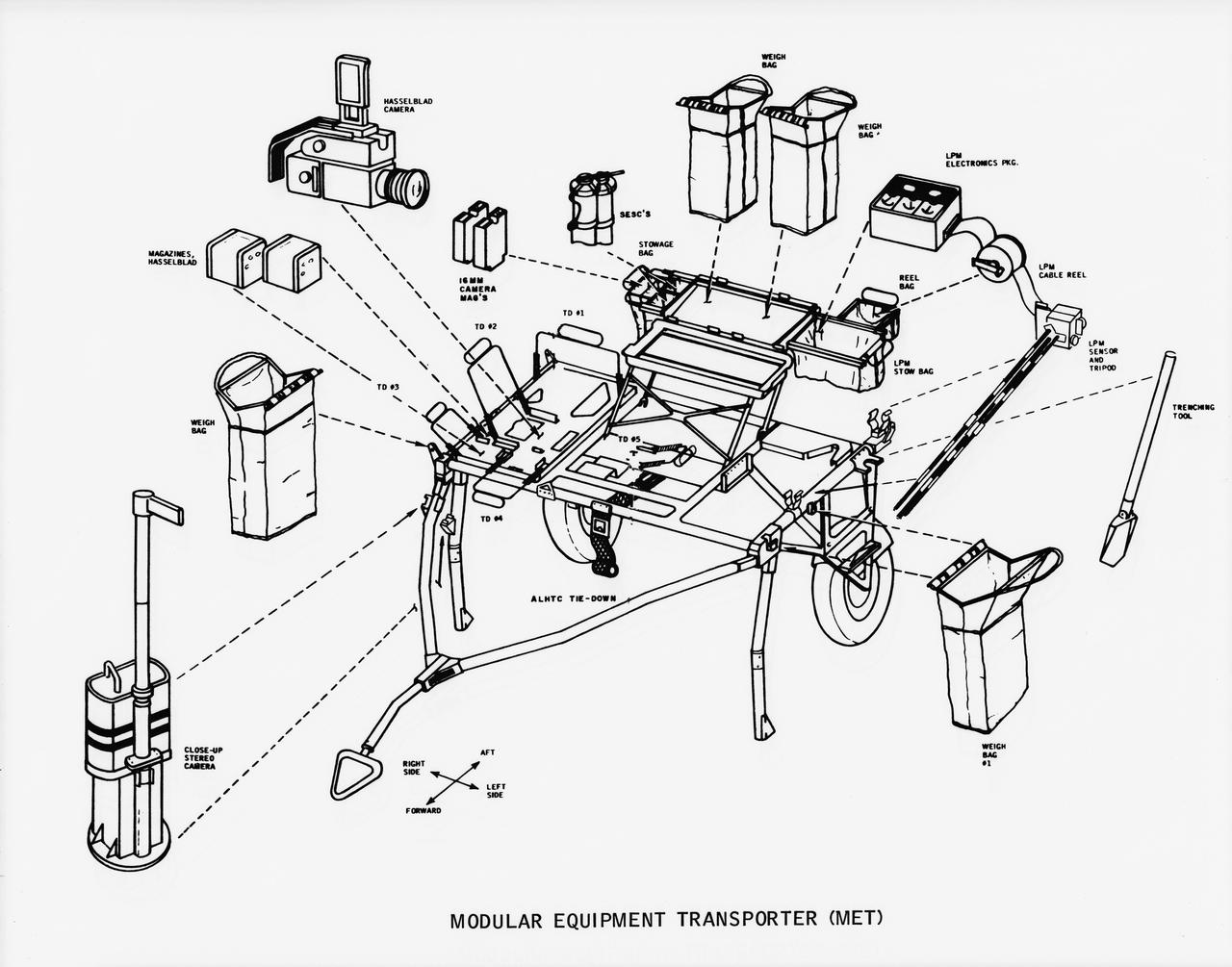
S70-50762 (November 1970) --- A line drawing illustrating layout view of the modular equipment transporter (MET) and its equipment. A MET (or Rickshaw, as it has been nicknamed) will be used on the lunar surface for the first time during the Apollo 14 lunar landing mission. The Rickshaw will serve as a portable workbench with a place for the Apollo lunar hand tools (ALHT) and their carrier, three cameras, two sample container bags, a special environment sample container (SESC), a lunar portable magnetometer (LPM) and spare film magazines.
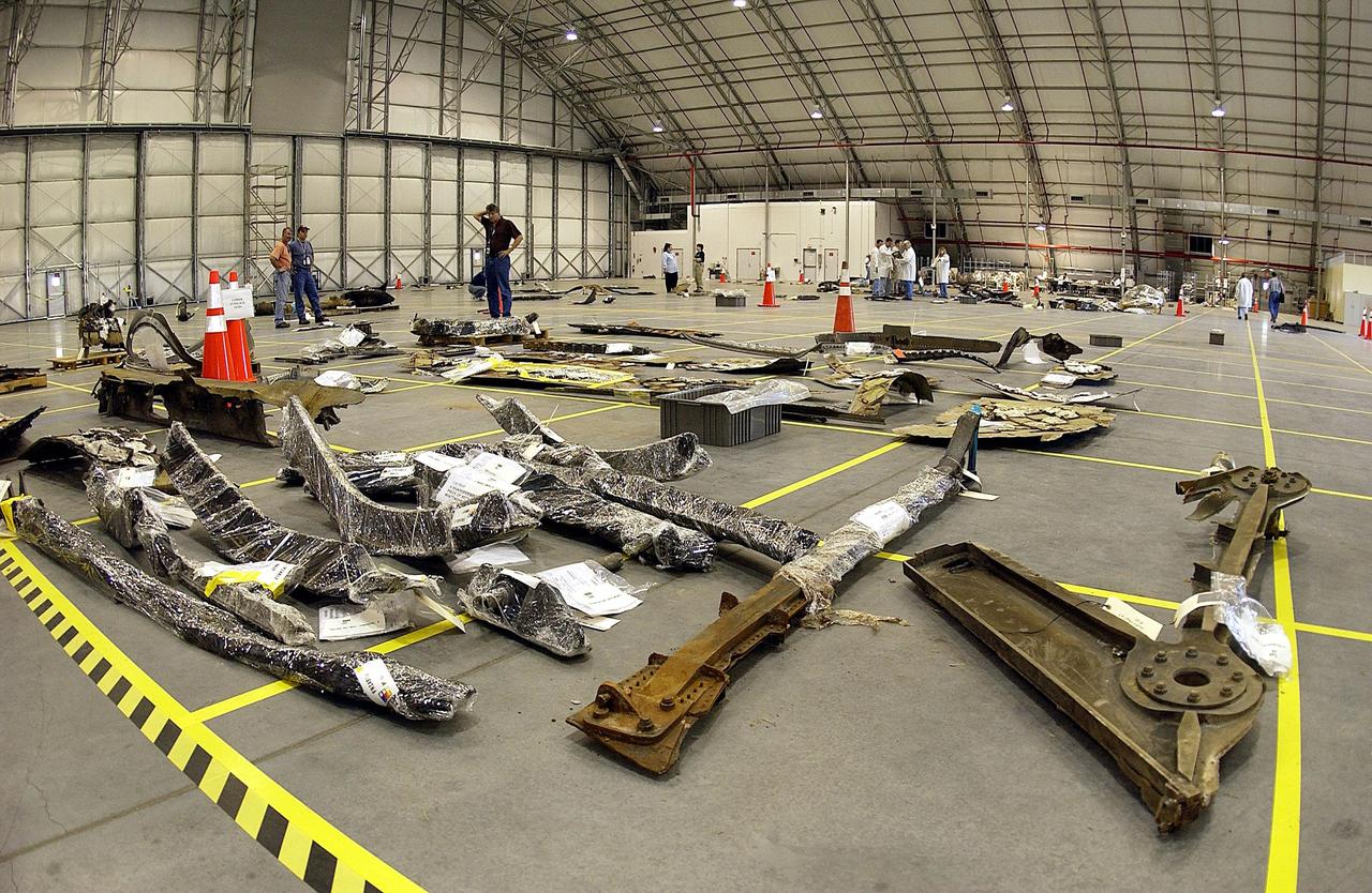
KENNEDY SPACE CENTER, FLA. -- The layout of the debris from the Space Shuttle Columbia is captured in this wide-angle view of a section of the RLV Hangar floor. The debris is being shipped to KSC from the collection point at Barksdale Air Force Base, Shreveport, La. As part of the ongoing investigation into the tragic accident that claimed Columbia and her crew of seven, workers will attempt to reconstruct the orbiter inside the hangar.
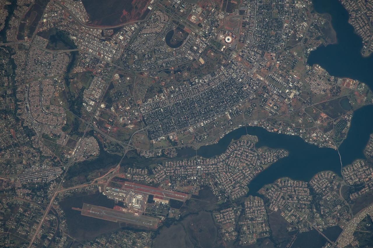
ISS040-E-005839 (28 May 2014) --- The Brasilia World Cup Stadium (top center) is featured in this image photographed by an Expedition 40 crew member on the International Space Station on May 28, 2014. Brazil?s national football stadium, the Estado Nacional, lies near the heart of the capital city of Brasilia. The new roof appears as a brilliant white ring in this image. The stadium is one of Brasilia?s largest buildings. Renovation began in 2010 and it is now the second most expensive stadium in the world, after Wembley Stadium in London, UK. To accommodate expected World Cup fans from all over the world, renovations for all modes of transportation, particularly airports, have been put in place in Brasilia and other host cities. Brasilia?s international airport can be seen lower left on the far side of Lake Paranoa. Brasilia is widely known for its modern building designs and city layout. Space station crew members have the best view of the city?s well-known ?swept wing? city layout ? giving the sense of a flying bird ? expressed in the curves of the boulevards (top). The stadium occupies the city center between the wings. The President Juscelino Kubitschek Bridge crosses the lake at bottom right. Its 1200-meter span gives scale to the city and stadium.
CAPE CANAVERAL, Fla. – In the Operations and Checkout Building at NASA's Kennedy Space Center in Florida, United Space Alliance EV_IV Integrated Operations work control specialist Jennifer Peterson, dressed in a flight-and-entry suit, stands in for an astronaut for a demonstration inside a mock-up of an Orion crew exploration vehicle. The mock-up details the interior components of the vehicle including seat layout and the subsystem components on the outside of the pressure vessel. Orion mock-ups also have been used to verify accessibility of the servicing locations at the launch pad and in the Vehicle Assembly Building. For information on the development of the Orion capsule, visit www.nasa.gov_orion. Photo credit: NASA_Jim Grossmann
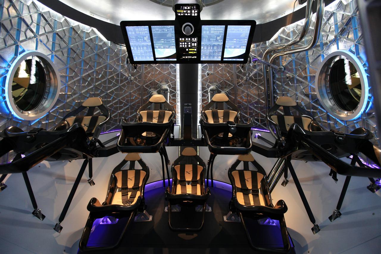
HAWTHORNE, Calif. - A look through the open hatch of the Dragon V2 reveals the layout and interior of the seven-crew capacity spacecraft. SpaceX unveiled the new spacecraft during a ceremony at its headquarters in Hawthorne, Calif. The Dragon V2 is designed to carry people into Earth's orbit and was developed in partnership with NASA's Commercial Crew Program under the Commercial Crew Integrated Capability agreement. SpaceX is one of NASA's commercial partners working to develop a new generation of U.S. spacecraft and rockets capable of transporting humans to and from Earth's orbit from American soil. Ultimately, NASA intends to use such commercial systems to fly U.S. astronauts to and from the International Space Station. Photo credit: NASA/Dimitri Gerondidakis
CAPE CANAVERAL, Fla. -- In Orbiter Processing Facility-3 at NASA's Kennedy Space Center in Florida, STS-133 Pilot Eric Boe and Commander Steve Lindsey (partially obscured) become familiar with the layout of the shuttle's cockpit. The astronauts are at Kennedy for the Crew Equipment Interface Test, or CEIT, which provides the crew with hands-on training and observation of shuttle and flight hardware for their mission to the International Space Station. Launch of the STS-133 mission on space shuttle Discovery is targeted for Nov. 1 at 4:33 p.m. EDT. Photo credit: NASA_Kim Shiflett
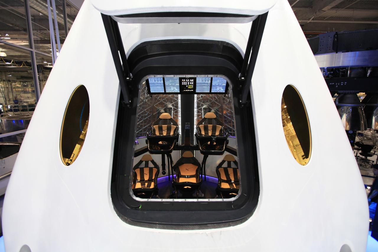
HAWTHORNE, Calif. - A look through the open hatch of the Dragon V2 reveals the layout and interior of the seven-crew capacity spacecraft. SpaceX unveiled the new spacecraft during a ceremony at its headquarters in Hawthorne, Calif. The Dragon V2 is designed to carry people into Earth's orbit and was developed in partnership with NASA's Commercial Crew Program under the Commercial Crew Integrated Capability agreement. SpaceX is one of NASA's commercial partners working to develop a new generation of U.S. spacecraft and rockets capable of transporting humans to and from Earth's orbit from American soil. Ultimately, NASA intends to use such commercial systems to fly U.S. astronauts to and from the International Space Station. Photo credit: NASA/Dimitri Gerondidakis
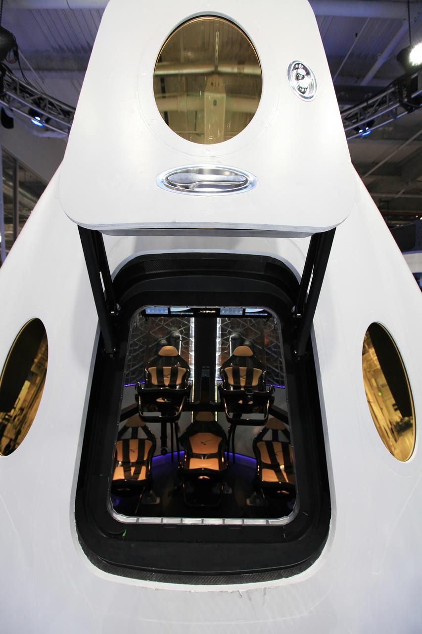
HAWTHORNE, Calif. - A look through the open hatch of the Dragon V2 reveals the layout and interior of the seven-crew capacity spacecraft. SpaceX unveiled the new spacecraft during a ceremony at its headquarters in Hawthorne, Calif. The Dragon V2 is designed to carry people into Earth's orbit and was developed in partnership with NASA's Commercial Crew Program under the Commercial Crew Integrated Capability agreement. SpaceX is one of NASA's commercial partners working to develop a new generation of U.S. spacecraft and rockets capable of transporting humans to and from Earth's orbit from American soil. Ultimately, NASA intends to use such commercial systems to fly U.S. astronauts to and from the International Space Station. Photo credit: NASA/Dimitri Gerondidakis

KENNEDY SPACE CENTER, FLA. - Appearing before the Columbia Accident Investigation Board are (left Michael Rudolphi, deputy director of NASA's Stennis Space Center in Bay St. Louis, Miss., and (right) Steve Altemus, shuttle test director at KSC. Over the course of two days, the Board's chairman, retired Navy Admiral Harold W. "Hal" Gehman Jr., and other board members have been hearing from experts discussing the role of the Kennedy Space Center in the Shuttle Program, Shuttle Safety and Debris Collection, Layout and Analysis and Forensic Metallurgy.
The main gate (Gate 7) of the Michoud Assembly Facility has been demolished and replaced following the tornado that struck the area in February 2017. The project included moving the gate to a position of 300 feet off the property line (away from Old Gentilly Blvd). The configuration included expanding the entrance to the gate from 2 lanes to 3 while maintaining 2 exit lanes. This layout provides for a guard post shelter rain canopy over two of the entrance lanes. Assessments and repairs continue on various structures and facilities across the facility.
CAPE CANAVERAL, Fla. – In the Operations and Checkout Building at NASA's Kennedy Space Center in Florida, United Space Alliance EV_IV Integrated Operations work control specialist Jennifer Peterson, dressed in a flight-and-entry suit, prepares to demonstrate the crew equipment inside a mock-up of an Orion crew exploration vehicle. The mock-up details the interior components of the vehicle including seat layout and the subsystem components on the outside of the pressure vessel. Orion mock-ups also have been used to verify accessibility of the servicing locations at the launch pad and in the Vehicle Assembly Building. For information on the development of the Orion capsule, visit www.nasa.gov_orion. Photo credit: NASA_Jim Grossmann
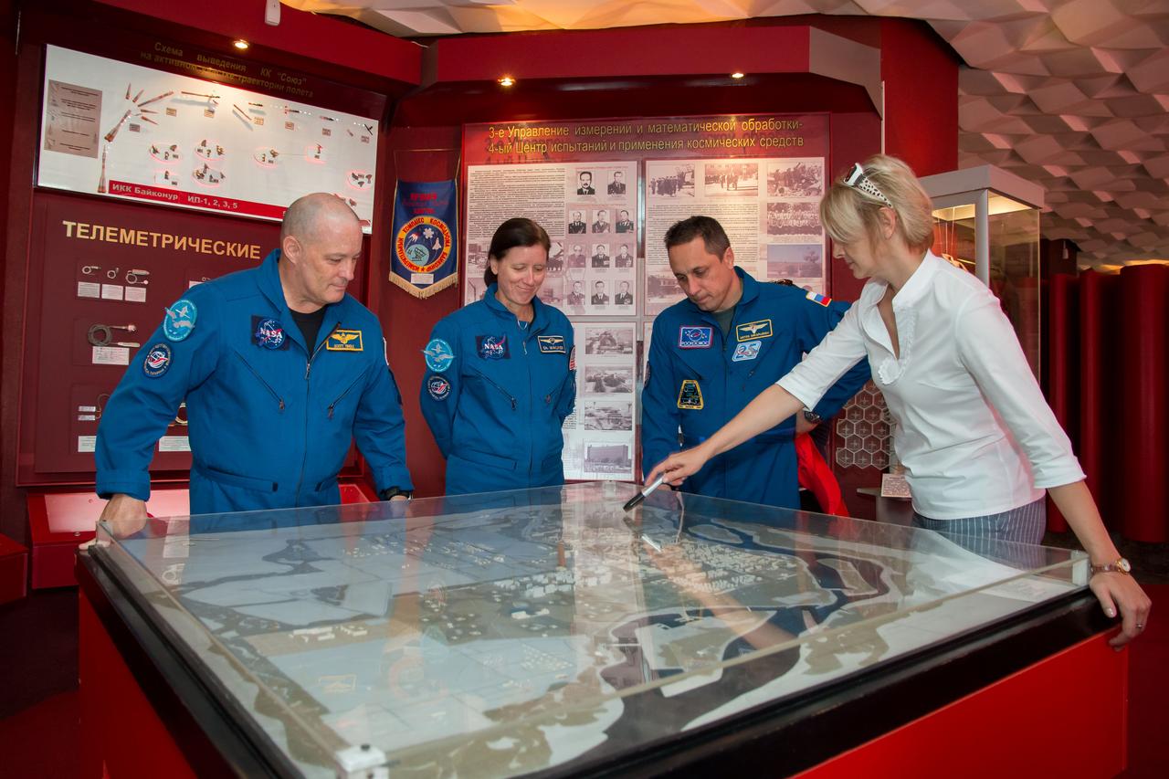
jsc2017e115218 (Sept.. 8, 2017) --- At the Space Museum in the town of Baikonur, Kazakhstan, Expedition 53-54 backup crewmembers Scott Tingle of NASA (left), Shannon Walker of NASA (center) and Anton Shkaplerov of Roscosmos (right) receive a briefing on the layout of the Baikonur Cosmodrome from a museum guide in a traditional pre-launch activity Sept. 8. They are serving as backups to the prime crewmembers, Joe Acaba of NASA, Alexander Misurkin of Roscosmos and Mark Vande Hei of NASA, who will launch on Sept. 13 from the Baikonur Cosmodrome in Kazakhstan on the Soyuz MS-06 spacecraft for a five and a half month mission on the International Space Station. Credit: NASA/Victor Zelentsov
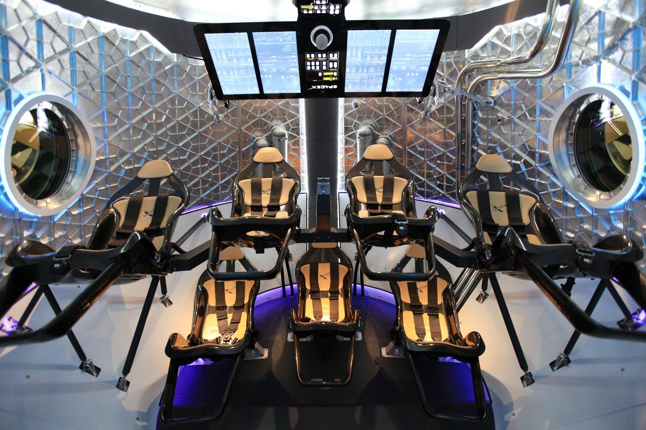
HAWTHORNE, Calif. - A look through the open hatch of the Dragon V2 reveals the layout and interior of the seven-crew capacity spacecraft. SpaceX unveiled the new spacecraft during a ceremony at its headquarters in Hawthorne, Calif. The Dragon V2 is designed to carry people into Earth's orbit and was developed in partnership with NASA's Commercial Crew Program under the Commercial Crew Integrated Capability agreement. SpaceX is one of NASA's commercial partners working to develop a new generation of U.S. spacecraft and rockets capable of transporting humans to and from Earth's orbit from American soil. Ultimately, NASA intends to use such commercial systems to fly U.S. astronauts to and from the International Space Station. Photo credit: NASA/Dimitri Gerondidakis
CAPE CANAVERAL, Fla. – In the Operations and Checkout Building at NASA's Kennedy Space Center in Florida, United Space Alliance EV_IV Integrated Operations work control specialist Jennifer Peterson, dressed in a flight-and-entry suit, demonstrates the placement of an astronaut inside a mock-up of an Orion crew exploration vehicle. The mock-up details the interior components of the vehicle including seat layout and the subsystem components on the outside of the pressure vessel. Orion mock-ups also have been used to verify accessibility of the servicing locations at the launch pad and in the Vehicle Assembly Building. For information on the development of the Orion capsule, visit www.nasa.gov_orion. Photo credit: NASA_Jim Grossmann
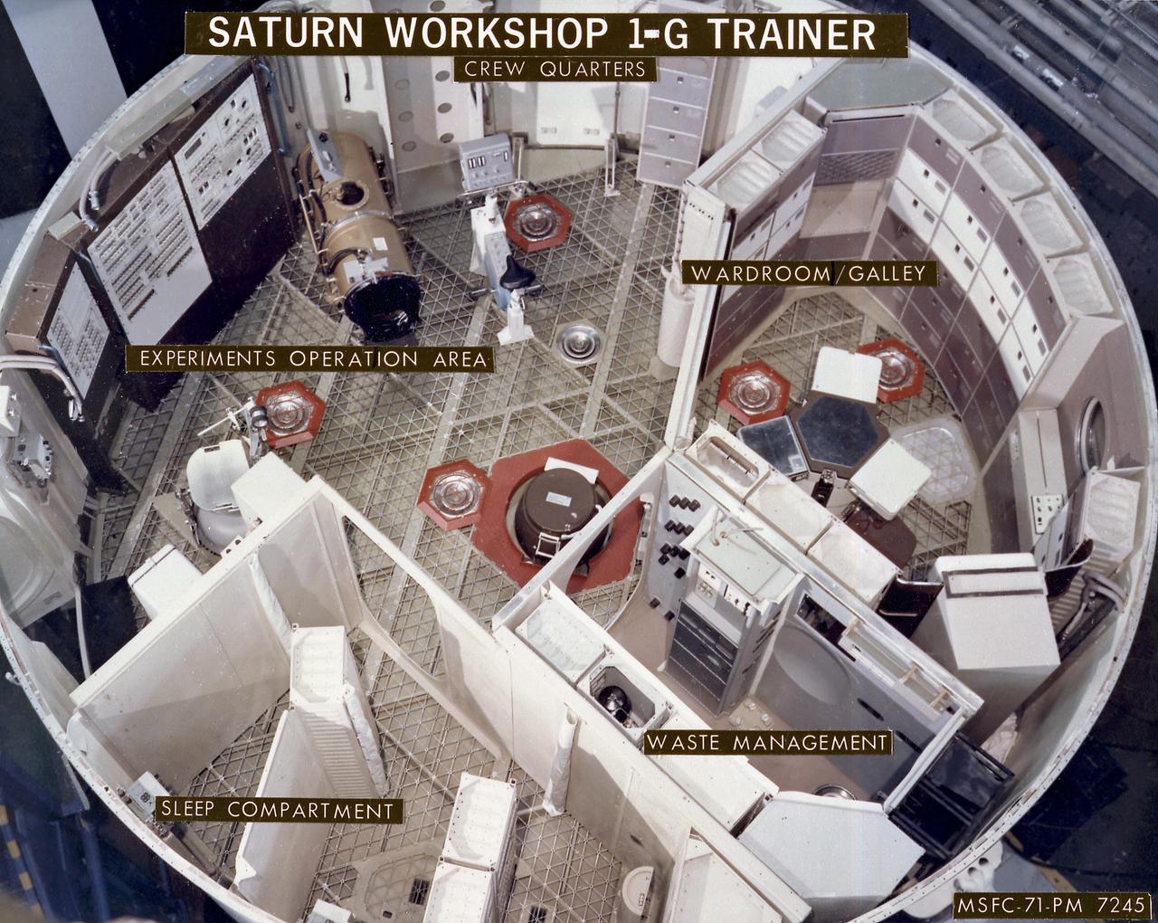
This image depicts a layout of the Skylab workshop 1-G trainer crew quarters. At left, in the sleep compartment, astronauts slept strapped to the walls of cubicles and showered at the center. Next right was the waste management area where wastes were processed and disposed. Upper right was the wardroom where astronauts prepared their meals and foods were stored. In the experiment operation area, upper left, against the far wall, was the lower-body negative-pressure device (Skylab Experiment M092) and the Ergometer for the vectorcardiogram experiment (Skylab Experiment M063). The trainers and mockups were useful in the developmental phase, while engineers and astronauts were still working out optimum designs. They provided much data applicable to the manufacture of the flight articles.
KENNEDY SPACE CENTER, FLA. - Sen. Bill Nelson (right), D-Fla., explains the layout of the glass cockpit to Sen. John F. Kerry, D-Mass., on the flight deck of orbiter Discovery during a tour of the Orbiter Processing Facility (OPF). The “bunny suits” they are wearing are clean room attire required for anyone coming in close proximity to Discovery, currently being prepared for flight on the next Space Shuttle mission. The tour of the OPF follows a public meeting Kerry held at the Dr. Kurt H. Debus Conference Facility at the Kennedy Space Center Visitor Complex. He said he chose to speak at KSC because it symbolizes America’s commitment to science, innovation and technology. He and Sen. John Edwards, D-N.C., are on a speaking tour prior to their appearance at the Democratic National Convention in Boston.
ISS008-E-21967 (21 April 2004) --- The five crewmembers onboard the International Space Station (ISS) went through the usual contingency evacuation drill, to acquaint the visitors with the general layout and sharpen their readiness for possible Station evacuation in the two Soyuz vehicles in case of an emergency. Pictured in the Unity node are cosmonauts Alexander Y. Kaleri (left), Expedition 8 flight engineer; Gennady I. Padalka, Expedition 9 commander, both representing Russia’s Federal Space Agency; astronauts C. Michael Foale, Expedition 8 commander and NASA ISS science officer; and Edward M. (Mike) Fincke, Expedition 9 NASA ISS science officer and flight engineer. European Space Agency (ESA) astronaut Andre Kuipers of the Netherlands is out of frame.
NASA7-726-063C (3 June 1998) --- The Space Shuttle Discovery approaches Russia's Mir space station in this 70mm photograph taken from the Mir. The nadir perspective affords a clear look at the layout of the cargo bay, revealing the open bay doors; the docking apparatus for connecting to Mir (near cabin), the tunnel; the SPACEHAB module (second element from aft); the Alpha Magnetic Spectrometer (near aft firewall); and the Ku-band antenna for communications (near cabin). Affixed to the lower right corner of the top of SPACEHAB is the external antenna for the SPACEHAB universal communications system (SHUCS). Discovery is the third Shuttle to visit Mir in a series of ten rendezvous (including nine docking) missions. Photo Credit: National Aeronautics and Space Administration (NASA) and the Russian Aviation and Space Agency.
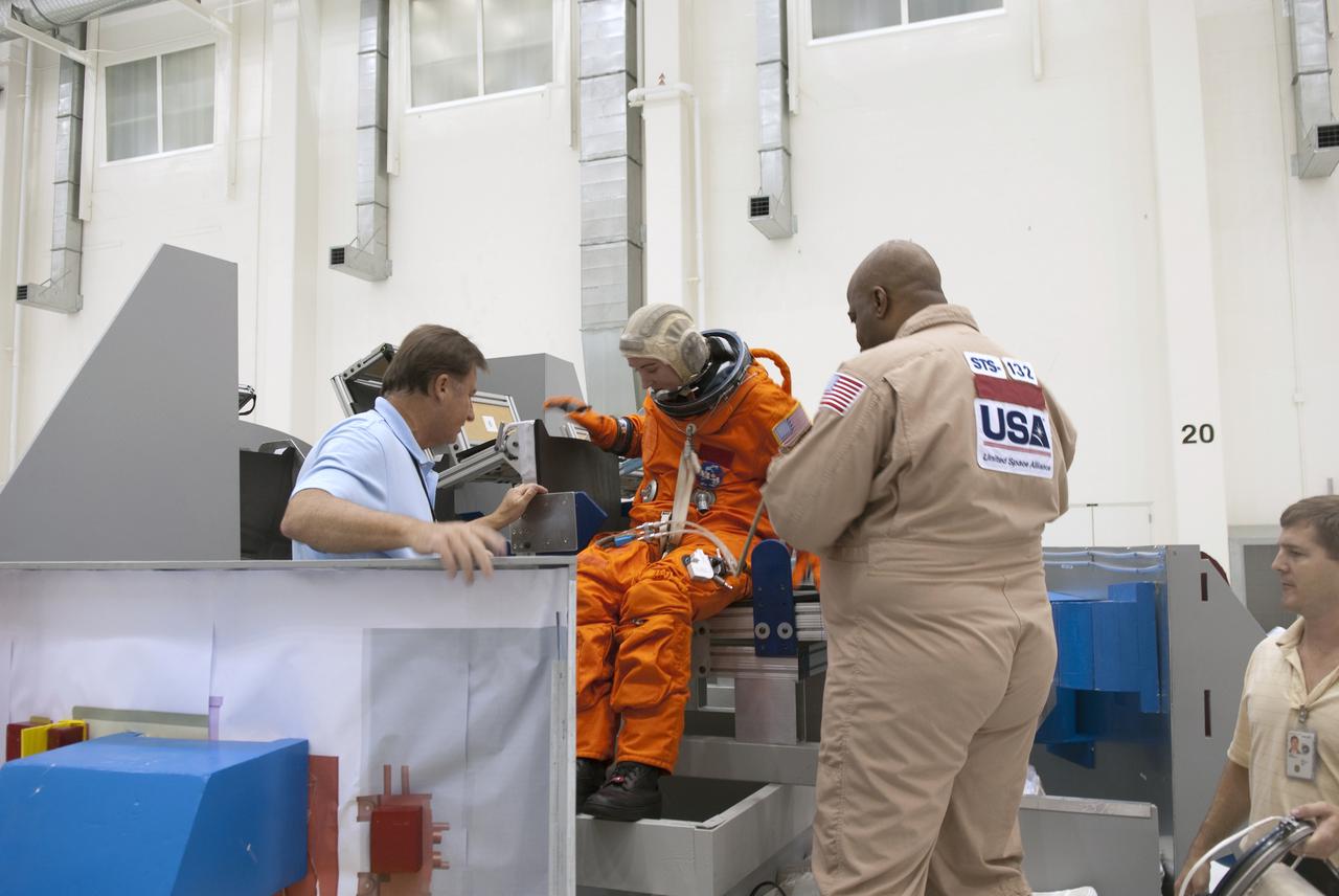
CAPE CANAVERAL, Fla. – In the Operations and Checkout Building at NASA's Kennedy Space Center in Florida, United Space Alliance space suit specialists prepare to demonstrate the placement of crew seats and equipment inside an Orion crew exploration vehicle mock-up. Crew escape equipment suit technician Andre Denard, the STS-132 crew chief, assists United Space Alliance EV_IV Integrated Operations work control specialist Jennifer Peterson, as she dresses in a flight-and-entry suit. Looking on is crew escape equipment suit engineer Thomas Carlton. The mock-up details the interior components of the vehicle including seat layout and the subsystem components on the outside of the pressure vessel. Orion mock-ups also have been used to verify accessibility of the servicing locations at the launch pad and in the Vehicle Assembly Building. For information on the development of the Orion capsule, visit www.nasa.gov_orion. Photo credit: NASA_Jim Grossmann
HOUSTON -- NASA Astronaut Lee Archambault performs an evaluation of reach and visibility of controls and displays during an end-of-year interior layout evaluation of The Boeing Company's CST-100 spacecraft. The evaluation at Boeing's Houston Product Support Center in Texas was part of the company's ongoing work supporting its funded Space Act Agreement with NASA's Commercial Crew Program, or CCP, during the Commercial Crew Integrated Capability, or CCiCap, initiative. CCP is intended to lead to the availability of commercial human spaceflight services for government and commercial customers to low-Earth orbit. Future development and certification initiatives eventually will lead to the availability of human spaceflight services for NASA to send its astronauts to the International Space Station, where critical research is taking place daily. For more information about CCP, go to http://www.nasa.gov/commercialcrew. Photo credit: Boeing
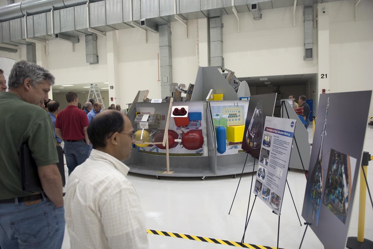
Photographic documentation showing the bldg. 9 ISS module mock-ups and trainers. Views include: various overall views of the configuration of the ISS module trainers on the floor of bldg. 9 (08445-46, 08449-51, 08458-61, 08464-65, 08469, 08471, 08476); various portions of the mock-ups (08447-48, 08470); views of the Node 2, Experiment Module and Logistics Module (08452); Node 2 (08453, 08466); Destiny and Node 2 (08454); Destiny, Unity and Airlock (08455); Zarya, Service Module and shuttle mock-ups (08456); Logistics Module and Experiment Module (08457, 08468); various views of Columbia, Node 2 and Destiny (08462-63); Columbus, Node 2, Experiment Module and Logistics Module (08467); U.S. Laboratory module (08472); Logistics Module (08473); module layout (08474); Logistics Module and Experiment Module (08475).
Brazil’s national football stadium, the Estado Nacíonal, lies near the heart of the capital city of Brasília. The roof appears as a brilliant white ring in this photograph taken from the International Space Station. The stadium is one of Brasília’s largest buildings. Renovation began in 2010, and it is now the second most expensive stadium in the world after Wembley Stadium in London. To accommodate World Cup fans visiting from all over the world, renovations were made to nearly all modes of transportation—particularly airports—in Brasília and other host cities. Brasília’s international airport is visible at lower right, on the far side of Lake Paranoá. (Note that the image is rotated so that north is to the left.) Brasília is widely known for its modern building designs and city layout. Astronauts have the best view of the city’s well-known “swept wing” city layout, which takes the form of a flying bird that is expressed in the curves of the boulevards (image left). The stadium occupies the city center, between the wings. Credit: ISS Read more/high res: <a href="http://earthobservatory.nasa.gov/NaturalHazards/view.php?id=83866&src=nha" rel="nofollow">earthobservatory.nasa.gov/NaturalHazards/view.php?id=8386...</a> Credit: <b><a href="http://www.earthobservatory.nasa.gov/" rel="nofollow"> NASA Earth Observatory</a></b> <b><a href="http://www.nasa.gov/audience/formedia/features/MP_Photo_Guidelines.html" rel="nofollow">NASA image use policy.</a></b> <b><a href="http://www.nasa.gov/centers/goddard/home/index.html" rel="nofollow">NASA Goddard Space Flight Center</a></b> enables NASA’s mission through four scientific endeavors: Earth Science, Heliophysics, Solar System Exploration, and Astrophysics. Goddard plays a leading role in NASA’s accomplishments by contributing compelling scientific knowledge to advance the Agency’s mission. <b>Follow us on <a href="http://twitter.com/NASAGoddardPix" rel="nofollow">Twitter</a></b> <b>Like us on <a href="http://www.facebook.com/pages/Greenbelt-MD/NASA-Goddard/395013845897?ref=tsd" rel="nofollow">Facebook</a></b> <b>Find us on <a href="http://instagram.com/nasagoddard?vm=grid" rel="nofollow">Instagram</a></b>
Astronaut James S. Voss, Expedition Two flight engineer, performs an electronics task in the Russian Zvezda Service Module on the International Space Station (ISS). Zvezda is linked to the Russian-built Functional Cargo Block (FGB), or Zarya, the first component of the ISS. Zarya was launched on a Russian Proton rocket prior to the launch of Unity, the first U.S.-built component to the ISS. Zvezda (Russian word for star), the third component of the ISS and the primary Russian contribution to the ISS, was launched by a three-stage Proton rocket on July 12, 2000. Zvezda serves as the cornerstone for early human habitation of the station, providing living quarters, a life support system, electrical power distribution, a data processing system, a flight control system, and a propulsion system. It also provides a communications system that includes remote command capabilities from ground flight controllers. The 42,000-pound module measures 43 feet in length and has a wing span of 98 feet. Similar in layout to the core module of Russia's Mir space station, it contains 3 pressurized compartments and 13 windows that allow ultimate viewing of Earth and space.
Early in Martian history, liquid water energetically carved the surface, forming channel systems that look remarkably similar to river valleys and drainage networks on Earth. Exactly how these channels formed -- by rainfall, snowmelt, or seepage from underground springs -- is often debated. The answer has important ramifications about the early Martian climate. Clues about the source of the water may indicate the shape, layout, and scale of the various tributaries in a channel system. Our image shows an example of just such a water-carved channel. The channel pattern, called "dendritic" because of its tree-like branching, begins at the top of the image and runs down over the rim of an ancient impact basin across the basin floor. The soil surface overlying these channels, and indeed the entire landscape, has been changed and reworked over the intervening millions of years, by the combined actions of wind and ice. Over time, the original channels become muted or even erased. Nevertheless, some characteristics of the smallest tributary channels are still visible at scales seen by HiRISE. http://photojournal.jpl.nasa.gov/catalog/PIA20337
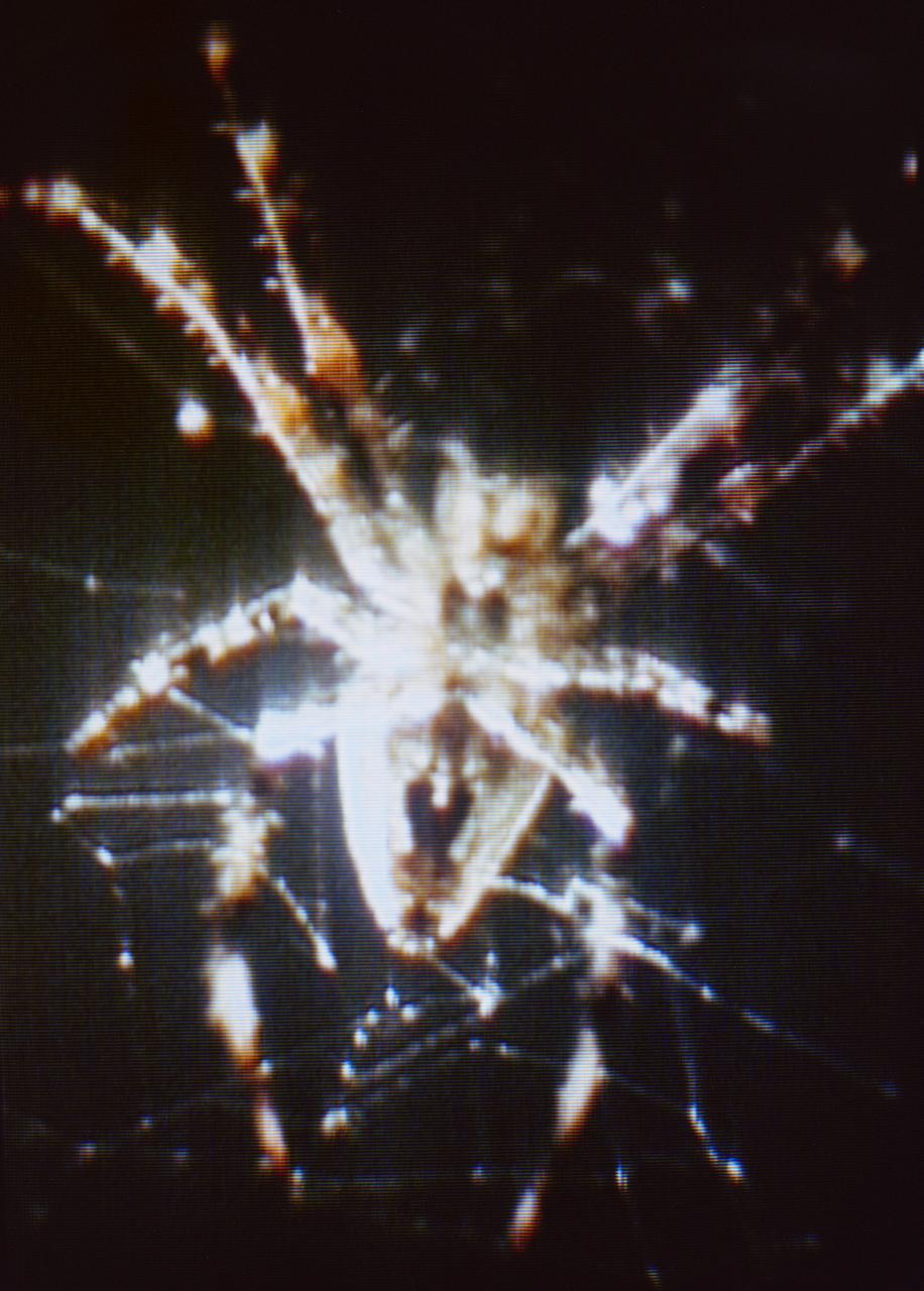
S73-34206 (8 Aug. 1973) --- A closeup view of Arabella, one of two Skylab 3 common cross spiders ?Araneus diadematus,? and the web it had spun in the zero-gravity of space aboard the Skylab space station cluster in Earth orbit. This is a photographic reproduction made a color television transmission aboard Skylab. During the 59-day Skylab 3 mission the two spiders, Arabella and Anita, were housed in an enclosure onto which a motion picture camera and a still camera were attached to record the spiders? attempts to build a web in the weightless environment. The spider experiment (ED52) was one of 25 experiments selected for Skylab by NASA from more than 3,400 experiment proposals submitted by 17-year-old Judith S. Miles of Lexington, Massachusetts. Anita died during the last week of the mission. THIS PHOTOGRAPH IS A GOVERNMENT PUBLICATION ?NOT SUBJECT TO COPYRIGHT. It may not be used to state or imply the endorsement by NASA or by any NASA employee of a commercial product, process or service, or used in any way that might mislead. Accordingly, it is requested that if this photograph is used in advertising and other commercial promotions, layout and copy be submitted to NASA prior to release. Photo credit: NASA
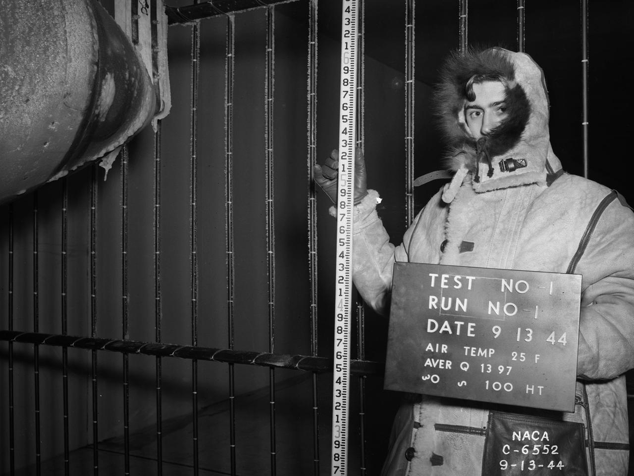
National Advisory Committee for Aeronautics (NACA) design engineers added the Icing Research Tunnel to the new Aircraft Engine Research Laboratory’s original layout to take advantage of the massive refrigeration system being constructed for the Altitude Wind Tunnel. The Icing Research Tunnel was built to study the formation of ice on aircraft surfaces and methods of preventing or eradicating that ice. Ice buildup adds extra weight, effects aerodynamics, and sometimes blocks airflow through engines. The Icing Research Tunnel is a closed-loop atmospheric wind tunnel with a 6- by 9-foot test section. The tunnel can produce speeds up to 300 miles per hour and temperatures from about 30 to –45⁰ F. Initially the tunnel used a spray bar system to introduce moisture into the airstream. NACA engineers struggled for nearly 10 years to perfect the spray system. The Icing Research Tunnel began testing in June of 1944. Initial testing, seen in this photograph, studied ice accumulation on propellers of a military aircraft. NACA reserach also produced a protected air scoop for the C–46 transport aircraft. A large number of C–46 aircraft were lost due to icing while flying supply runs over the Himalayas during World War II.
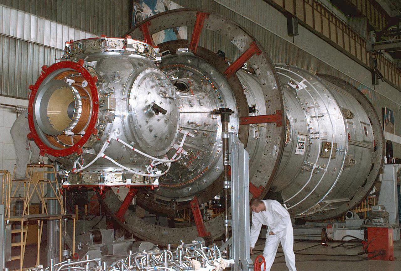
The Zvezda Service Module, the first Russian contribution and third element to the International Space Station (ISS), is shown under construction in the Krunichev State Research and Production Facility (KhSC) in Moscow. Russian technicians work on the module shortly after it completed a pressurization test. In the foreground is the forward portion of the module, including the spherical transfer compartment and its three docking ports. The forward port docked with the cornected Functional Cargo Block, followed by Node 1. Launched via a three-stage Proton rocket on July 12, 2000, the Zvezda Service Module serves as the cornerstone for early human habitation of the Station, providing living quarters, life support system, electrical power distribution, data processing system, flight control system, and propulsion system. It also provides a communications system that includes remote command capabilities from ground flight controllers. The 42,000-pound module measures 43 feet in length and has a wing span of 98 feet. Similar in layout to the core module of Russia's Mir space station, it contains 3 pressurized compartments and 13 windows that allow ultimate viewing of Earth and space.
Astronauts Frank L. Culbertson, Jr. (left), Expedition Three mission commander, and Daniel W. Bursch, Expedition Four flight engineer, work in the Russian Zvezda Service Module on the International Space Station (ISS). Zvezda is linked to the Russian built Functional Cargo Block (FGB), or Zarya, the first component of the ISS. Zarya was launched on a Russian Proton rocket prior to the launch of Unity. The third component of the ISS, Zvezda (Russian word for star), the primary Russian contribution to the ISS, was launched by a three-stage Proton rocket on July 12, 2000. Zvezda serves as the cornerstone for early human habitation of the Station, providing living quarters, a life support system, electrical power distribution, a data processing system, a flight control system, and a propulsion system. It also provides a communications system that includes remote command capabilities from ground flight controllers. The 42,000 pound module measures 43 feet in length and has a wing span of 98 feet. Similar in layout to the core module of Russia's Mir space station, it contains 3 pressurized compartments and 13 windows that allow ultimate viewing of Earth and space.

Aboard the International Space Station (ISS), Cosmonaut and Expedition Three flight engineer Vladimir N. Dezhurov, representing Rosaviakosmos, talks with flight controllers from the Zvezda Service Module. Russian-built Zvezda is linked to the Functional Cargo Block (FGB), or Zarya, the first component of the ISS. Zarya was launched on a Russian Proton rocket prior to the launch of Unity. The third component of the ISS, Zvezda (Russian word for star), the primary Russian contribution to the ISS, was launched by a three-stage Proton rocket on July 12, 2000. Zvezda serves as the cornerstone for early human habitation of the Station, providing living quarters, a life support system, electrical power distribution, a data processing system, flight control system, and propulsion system. It also provides a communications system that includes remote command capabilities from ground flight controllers. The 42,000-pound module measures 43 feet in length and has a wing span of 98 feet. Similar in layout to the core module of Russia's Mir space station, it contains 3 pressurized compartments and 13 windows that allow ultimate viewing of Earth and space.
Cosmonaut Yury I. Onufrienko, Expedition Four mission commander, uses a communication system in the Russian Zvezda Service Module on the International Space Station (ISS). The Zvezda is linked to the Russian-built Functional Cargo Block (FGB) or Zarya, the first component of the ISS. Zarya was launched on a Russian Proton rocket prior to the launch of Unity. The third component of the ISS, Zvezda (Russian word for star), the primary Russian contribution to the ISS, was launched by a three-stage Proton rocket on July 12, 2000. Zvezda serves as the cornerstone for early human habitation of the station, providing living quarters, a life support system, electrical power distribution, a data processing system, flight control system, and propulsion system. It also provides a communications system that includes remote command capabilities from ground flight controllers. The 42,000-pound module measures 43 feet in length and has a wing span of 98 feet. Similar in layout to the core module of Russia's Mir space station, it contains 3 pressurized compartments and 13 windows that allow ultimate viewing of Earth and space.
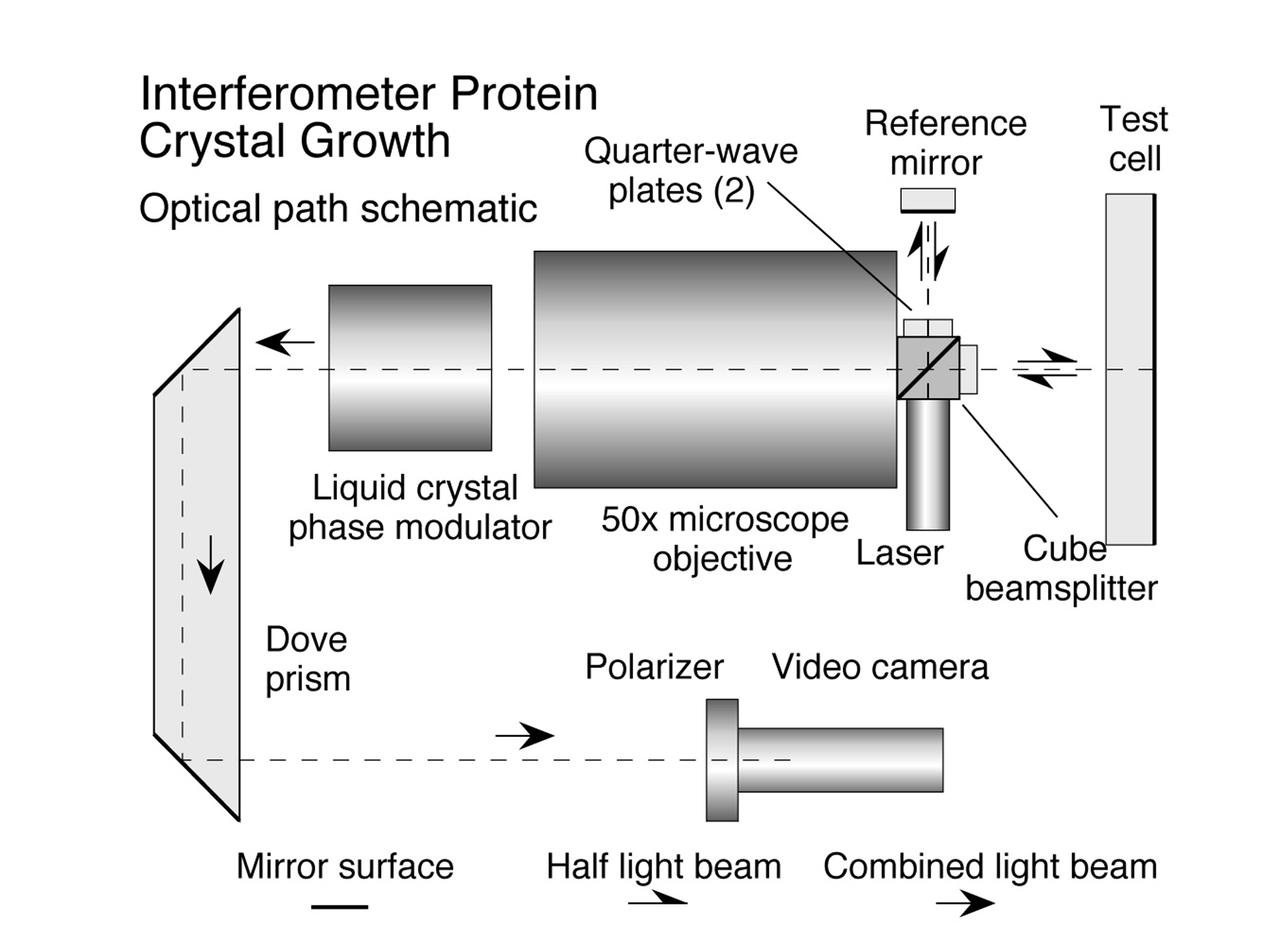
The Interferometer Protein Crystal Growth (IPCG) experiment was designed to measure details of how protein molecules move through a fluid. It was flown on the STS-86 mission for use aboard Russian Space Station Mir in 1998. It studied aspects of how crystals grow - and what conditions lead to the best crystals, details that remain a mystery. IPCG produces interference patterns by spilitting then recombining laser light. This let scientists see how fluid densities - and molecular diffusion - change around a crystal as it grows in microgravity. The heart of the IPCG apparatus is the interferometer cell comprising the optical bench, microscope, other optics, and video camera. IPCG experiment cells are made of optical glass and silvered on one side to serve as a mirror in the interferometer system that visuzlizes crystals and conditions around them as they grow inside the cell. This diagram shows the optical layout. The principal investigator was Dr. Alexander McPherson of University of California, Irvine. Co-investigators are William Witherow and Dr. Marc Pusey of NASA's Marshall Space Flight Center (MSFC).
CAPE CANAVERAL, Fla. – In the Space Station Processing Facility at NASA's Kennedy Space Center in Florida, mission specialist Kathryn "Kay" Hire, left, a crew member on space shuttle Endeavour's STS-130 mission, discusses the layout of the Tranquility Node 3 module in which she is standing with Chris Hardcastle, an STS-130 flight crew representative with United Space Alliance. Tranquility is a pressurized module that will provide room for many of the International Space Station's life support systems. Attached to the node is a cupola, a unique work station with six windows on its sides and one on top. Tranquility is the payload for the STS-130 mission. The module was built for the European Space Agency by Alenia Spazio in Turin, Italy. Cupola resembles a circular bay window that will provide a vastly improved view of the station's exterior. Just under 10 feet in diameter, the module will accommodate two crew members and portable workstations that can control station and robotic activities. The multi-directional view will allow the crew to monitor spacewalks and docking operations, as well as provide a spectacular view of Earth and other celestial objects. Endeavour is targeted to launch Feb. 4, 2010. Photo credit: NASA/Jack Pfaller
A Bell P-39 Airacobra in the NACA Aircraft Engine Research Laboratory’s Icing Research Tunnel for a propeller deicing study. The tunnel, which began operation in June 1944, was built to study the formation of ice on aircraft surfaces and methods of preventing or eradicating that ice. Ice buildup adds extra weight to aircraft, effects aerodynamics, and sometimes blocks airflow through engines. NACA design engineers added the Icing Research Tunnel to the new AERL’s original layout to take advantage of the massive refrigeration system being constructed for the Altitude Wind Tunnel. The Icing Research Tunnel is a closed-loop atmospheric wind tunnel with a 6- by 9-foot test section. The tunnel can produce speeds up to 300 miles per hour and temperatures from about 30 to -45⁰ F. During World War II AERL researchers analyzed different ice protection systems for propeller, engine inlets, antennae, and wings in the icing tunnel. The P-39 was a vital low-altitude pursuit aircraft of the US during the war. NACA investigators investigated several methods of preventing ice buildup on the P-39’s propeller, including the use of internal and external electrical heaters, alcohol, and hot gases. They found that continual heating of the blades expended more energy than the aircraft could supply, so studies focused on intermittent heating. The results of the wind tunnel investigations were then compared to actual flight tests on aircraft.

ISS038-E-016506 (12 Dec. 2013) --- A nighttime view of Salt Lake City, Utah is featured in this image photographed by an Expedition 38 crew member on the International Space Station. The Salt Lake City metropolitan area is located along the western front of the Wasatch Range in northern Utah. Viewed at night from the vantage point of the space station, the regular north-south and east-west layout of street grids typical of western U.S. cities is clearly visible. Known as "the crossroads of the West", the headquarters of The Church of Jesus Christ of Latter-day Saints (also known as the LDS Church and informally as the Mormon Church), and the state capital of Utah, Salt Lake City was founded in 1847 by Brigham Young together with other followers of the Mormon faith. The Salt Lake City metropolitan area today is included in the larger urban Wasatch Front region of Utah which includes over two million people (approximately 80 percent of the population of the state). Both the color of the city lights and their density provide clues to the character of the urban fabric -- yellow gold lights generally indicate major roadways such as Interstate Highway 15 that passes through the center of the metropolitan area (center, left to right), while bright white clusters of lights are associated with city centers, commercial, and industrial areas. In contrast, residential and suburban areas are recognizable due to diffuse and relatively dim lighting (center left). The Wasatch Range to the east is largely dark, as are several large urban parks and golf courses located within the illuminated urban areas.
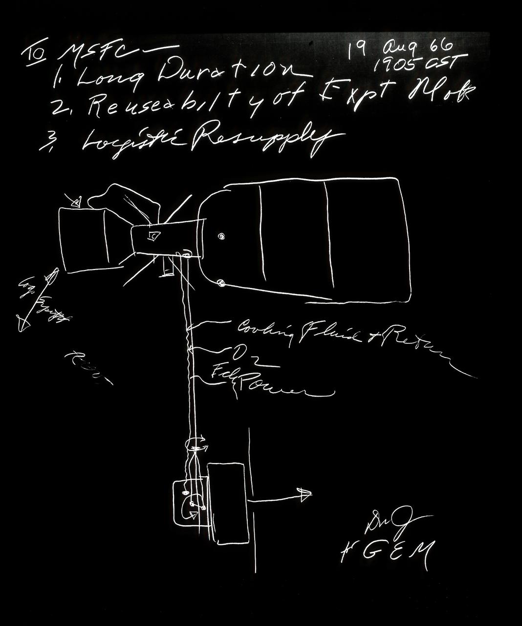
Seldom in aerospace history has a major decision been as promptly and concisely recorded as with the Skylab shown in this sketch. At a meeting at the Marshall Space Flight Center on August 19, 1966, George E. Mueller, NASA Associate Administrator for Marned Space Flight, used a felt pen and poster paper to pin down the final conceptual layout for the budding space station's (established as the Skylab in 1970) major elements. General Davy Jones, first program director, added his initials and those of Dr. Mueller in the lower right corner. The goals of the Skylab were to enrich our scientific knowledge of the Earth, the Sun, the stars, and cosmic space; to study the effects of weightlessness on living organisms, including man; to study the effects of the processing and manufacturing of materials utilizing the absence of gravity; and to conduct Earth resource observations. The Skylab also conducted 19 selected experiments submitted by high school students. Skylab's 3 different 3-man crews spent up to 84 days in Earth orbit. The Marshall Space Flight Center (MSFC) had responsibility for developing and integrating most of the major components of the Skylab: the Orbital Workshop (OWS), Airlock Module (AM), Multiple Docking Adapter (MDA), Apollo Telescope Mount (ATM), Payload Shroud (PS), and most of the experiments. MSFC was also responsible for providing the Saturn IB launch vehicles for three Apollo spacecraft and crews and a Saturn V launch vehicle for the Skylab.
A National Advisory Committee for Aeronautics (NACA) researcher measures the ice thickness on a landing antenna model in the Icing Research Tunnel at the Aircraft Engine Research Laboratory. NACA design engineers added the Icing Research Tunnel to the original layout of the new Aircraft Engine Research Laboratory to take advantage of the massive refrigeration system being built for the Altitude Wind Tunnel. The Icing Research Tunnel was built to study the formation of ice on aircraft surfaces and methods of preventing or eradicating that ice. Ice buildup adds extra weight, effects aerodynamics, and sometimes blocks air flow through engines. The Icing Research Tunnel is a closed-loop atmospheric wind tunnel with a 6- by 9-foot test section. Carrier Corporation refrigeration equipment reduced the internal air temperature to -45 degrees F and a spray bar system injected water droplets into the air stream. The 24-foot diameter drive fan, seen in this photograph, created air flows velocities up to 400 miles per hour. The Icing Research Tunnel began testing in June of 1944. Early testing, seen in this photograph, studied ice accumulation on propellers and antenna of a military aircraft. The Icing Research Tunnel’s designers, however, struggled to develop a realistic spray system since they did not have access to data on the size of naturally occurring water droplets. The system would have to generate small droplets, distribute them uniformly throughout the airstream, and resist freezing and blockage. For five years a variety of different designs were painstakingly developed and tested before the system was perfected.
A Bell P-39 Airacobra in the NACA Aircraft Engine Research Laboratory’s Icing Research Tunnel for a propeller deicing study. The tunnel, which began operation in June 1944, was built to study the formation of ice on aircraft surfaces and methods of preventing or eradicating that ice. Ice buildup adds extra weight to aircraft, effects aerodynamics, and sometimes blocks airflow through engines. NACA design engineers added the Icing Research Tunnel to the new AERL’s original layout to take advantage of the massive refrigeration system being constructed for the Altitude Wind Tunnel. The Icing Research Tunnel is a closed-loop atmospheric wind tunnel with a 6- by 9-foot test section. The tunnel can produce speeds up to 300 miles per hour and temperatures from about 30 to –45⁰ F. During World War II AERL researchers analyzed different ice protection systems for propeller, engine inlets, antennae, and wings in the icing tunnel. The P-39 was a vital low-altitude pursuit aircraft of the US during the war. NACA investigators investigated several methods of preventing ice buildup on the P-39’s propeller, including the use of internal and external electrical heaters, alcohol, and hot gases. They found that continual heating of the blades expended more energy than the aircraft could supply, so studies focused on intermittent heating. The results of the wind tunnel investigations were then compared to actual flight tests on aircraft.
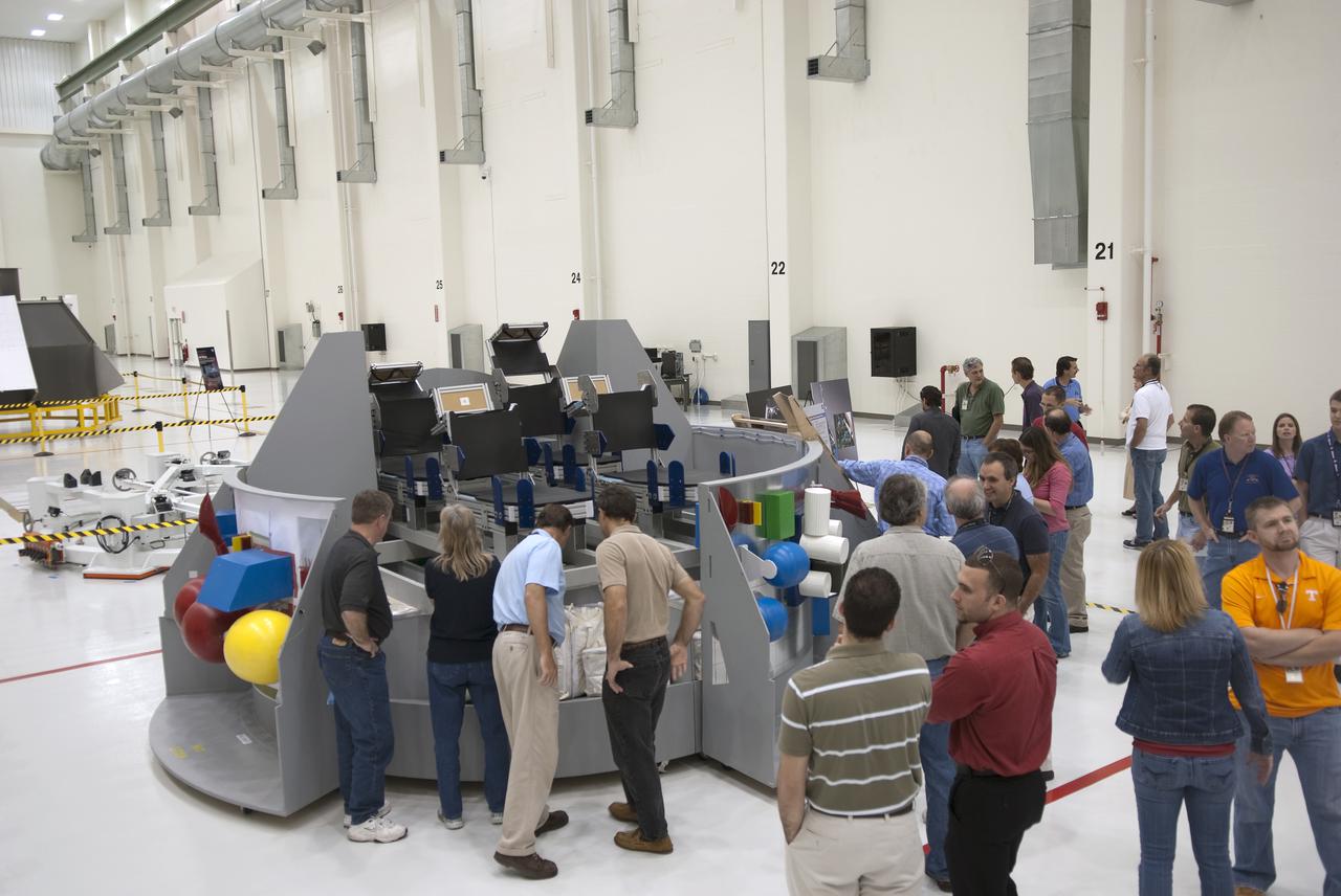
CAPE CANAVERAL, Fla. - On Launch Pad 39A at NASA's Kennedy Space Center, the members of space shuttle Atlantis' STS-132 crew are familiarized with the pad's layout and protocols during emergency exit training. In the blue flight suits, from left, are Commander Ken Ham; Mission Specialists Steve Bowen, Michael Good and Garrett Reisman; Pilot Tony Antonelli; and Mission Specialist Piers Sellers. The crew is participating in training in preparation for their Terminal Countdown Demonstration Test, or TCDT, a dress rehearsal for launch. TCDT provides each shuttle crew and launch team the opportunity to participate in various simulated countdown activities, including equipment familiarization and emergency procedures. On the STS-132 mission, the six-member crew will deliver an Integrated Cargo Carrier, or ICC, and the Russian-built Mini-Research Module-1, or MRM-1, to the International Space Station aboard space shuttle Atlantis. The ICC is an unpressurized flat bed pallet and keel yoke assembly used to support the transfer of exterior cargo from the shuttle to the space station. The MRM-1, known as Rassvet, is the second in a series of new pressurized components for Russia and will be permanently attached to the Earth-facing port of the Zarya control module. Rassvet, which translates to 'dawn,' will be used for cargo storage and will provide an additional docking port to the station. STS-132 is the 34th mission to the station and the 132nd shuttle mission overall. Atlantis is targeted to launch on May 14 at 2:19 p.m. For information on the STS-132 mission, visit http:__www.nasa.gov_mission_pages_shuttle_shuttlemissions_sts132_index.html. Photo credit: NASA_Jim Grossmann
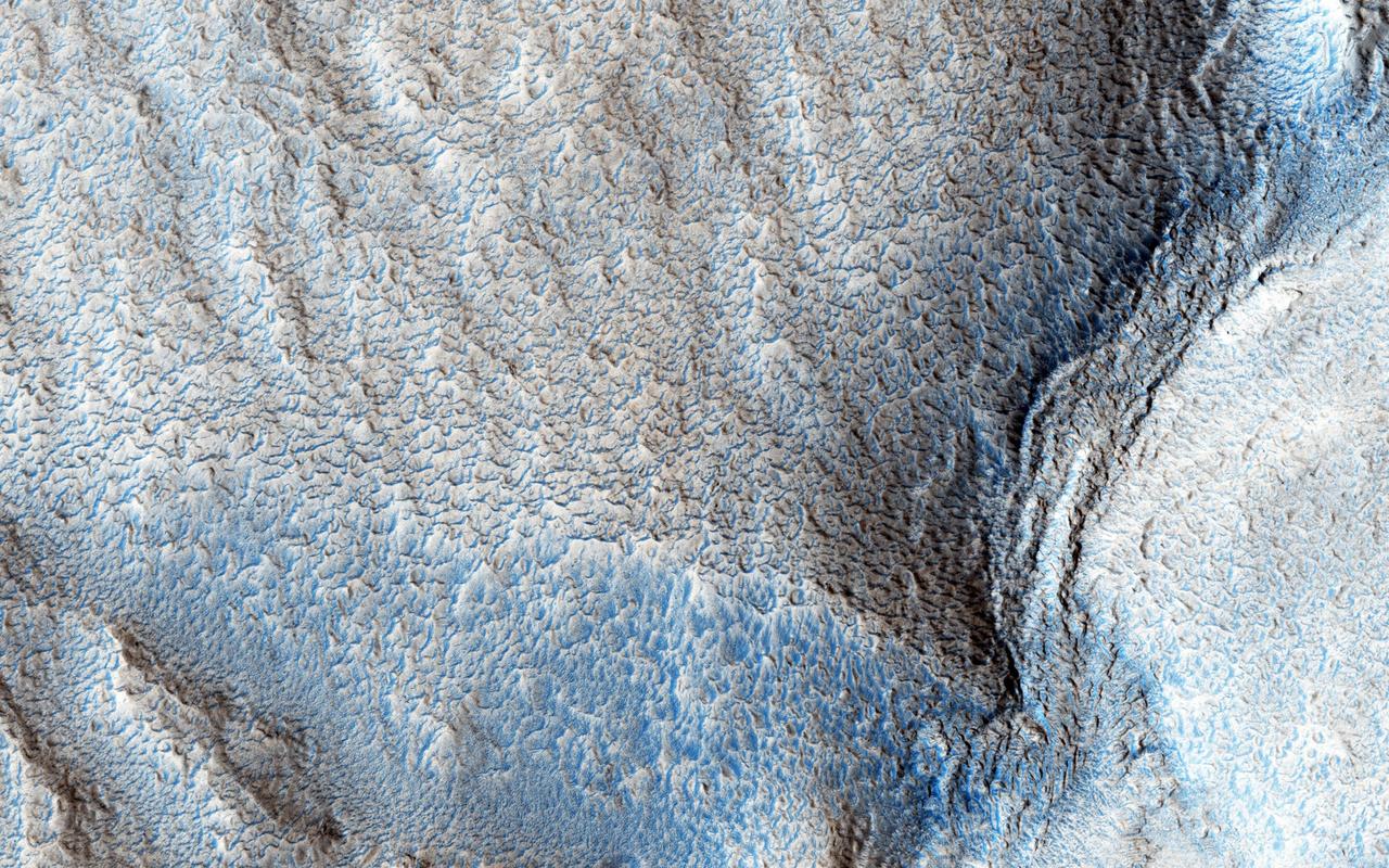
This VIS image highlights the dune form/dune density aspects of Olypmia Undae. In the center there is a brighter, diagonal region of few dunes. These dunes are the arc or crescent shape of barchan dunes. As more sand becomes available the barchan dunes begin to merge into transverse dunes. The region of dunes surrounding the bright swath still have the underlying surface visible, and the transverse dunes have a lace-like layout. In the regions with a significant abundance of sand have developed the tightly packed transverse dunes with the wave-like distribution. Olympia Undae is a vast dune field in the north polar region of Mars. It consists of a broad sand sea or erg that partly rings the north polar cap from about 120° to 240°E longitude and 78° to 83°N latitude. The dune field covers an area of approximately 470,000 km2 (bigger than California, smaller than Texas). Olympia Undae is the largest continuous dune field on Mars. Olympia Undae is not the only dune field near the north polar cap, several other smaller fields exist in the same latitude, but in other ranges of longitude, e.g. Abolos and Siton Undae. Barchan and transverse dune forms are the most common. In regions with limited available sand individual barchan dunes will form, the surface beneath and between the dunes is visible. In regions with large sand supplies, the sand sheet covers the underlying surface, and dune forms are found modifying the surface of the sand sheet. In this case transverse dunes are more common. Barchan dunes "point" down wind, transverse dunes are more linear and form parallel to the wind direction. The "square" shaped transverse dunes in Olympia Undae are due to two prevailing wind directions. The density of dunes and the alignments of the dune crests varies with location, controlled by the amount of available sand and the predominant winds over time. The Odyssey spacecraft has spent over 15 years in orbit around Mars, circling the planet more than 71,000 times. It holds the record for longest working spacecraft at Mars. THEMIS, the IR/VIS camera system, has collected data for the entire mission and provides images covering all seasons and lighting conditions. Over the years many features of interest have received repeated imaging, building up a suite of images covering the entire feature. From the deepest chasma to the tallest volcano, individual dunes inside craters and dune fields that encircle the north pole, channels carved by water and lava, and a variety of other feature, THEMIS has imaged them all. For the next several months the image of the day will focus on the Tharsis volcanoes, the various chasmata of Valles Marineris, and the major dunes fields. We hope you enjoy these images! Orbit Number: 13238 Latitude: 80.7247 Longitude: 173.91 Instrument: VIS Captured: 2004-12-08 09:25 https://photojournal.jpl.nasa.gov/catalog/PIA22296