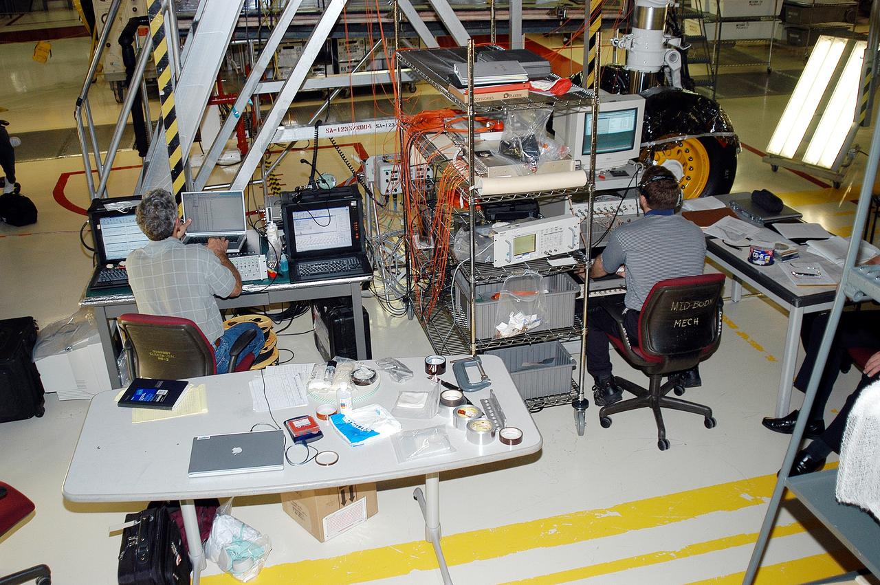
KENNEDY SPACE CENTER, FLA. - In the Orbiter Processing Facility, Eric Madaras (left), NASA-Langley Research Center, and Jim McGee, The Boeing Company, Huntington Beach, Calif., conduct impulse tests on the right wing leading edge (WLE) of Space Shuttle Endeavour. The tests monitor how sound impulses propagate through the WLE area. The data collected will be analyzed to explore the possibility of adding new instrumentation to the wing that could automatically detect debris or micrometeroid impacts on the Shuttle while in flight. The study is part of the initiative ongoing at KSC and around the agency to return the orbiter fleet to flight status.
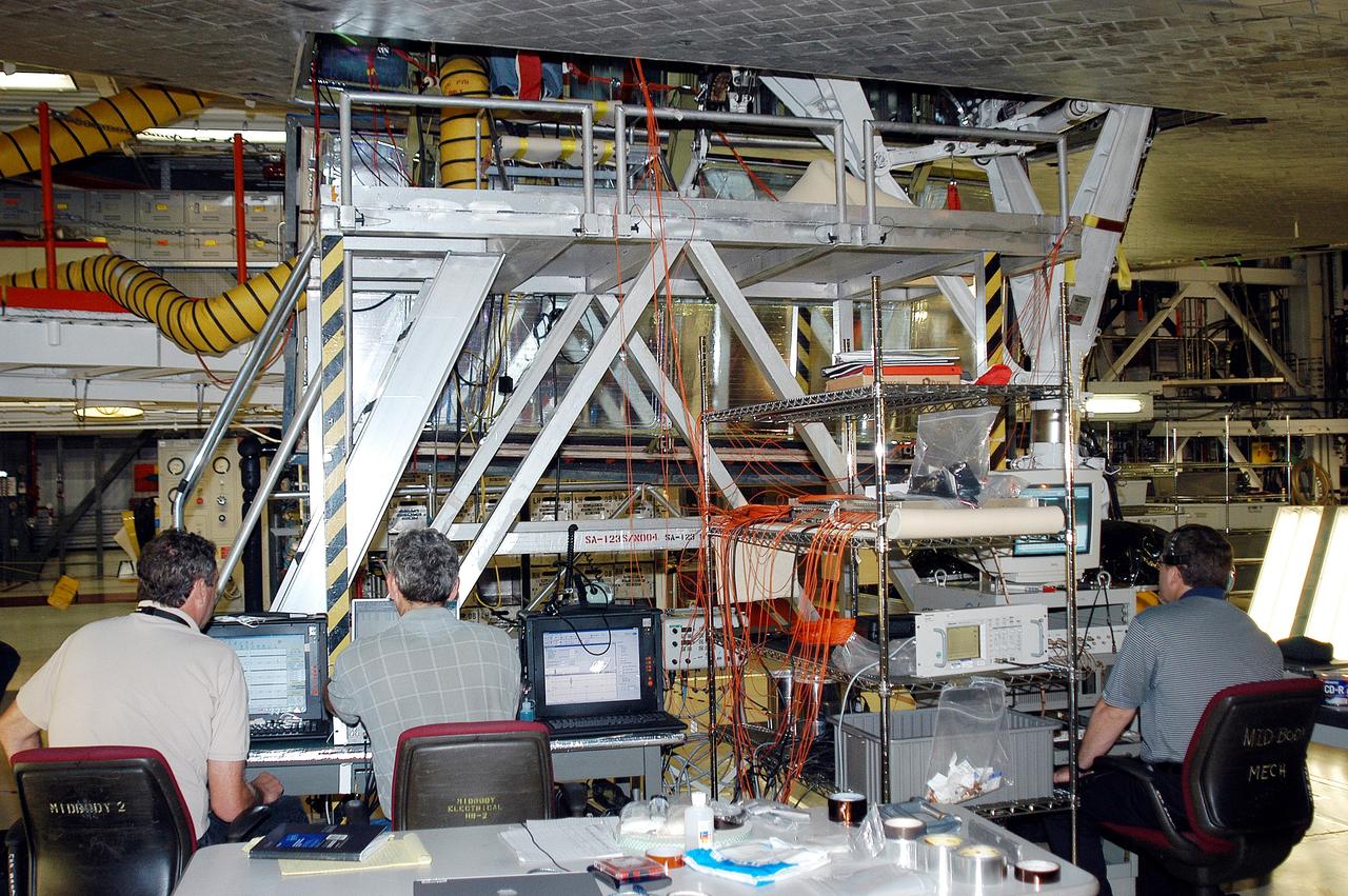
KENNEDY SPACE CENTER, FLA. - In the Orbiter Processing Facility, Bill Prosser (left) and Eric Madaras, NASA-Langley Research Center, and Jim McGee (right), The Boeing Company, Huntington Beach, Calif., conduct impulse tests on the right wing leading edge (WLE) of Space Shuttle Endeavour. The tests monitor how sound impulses propagate through the WLE area. The data collected will be analyzed to explore the possibility of adding new instrumentation to the wing that could automatically detect debris or micrometeroid impacts on the Shuttle while in flight. The study is part of the initiative ongoing at KSC and around the agency to return the orbiter fleet to flight status.
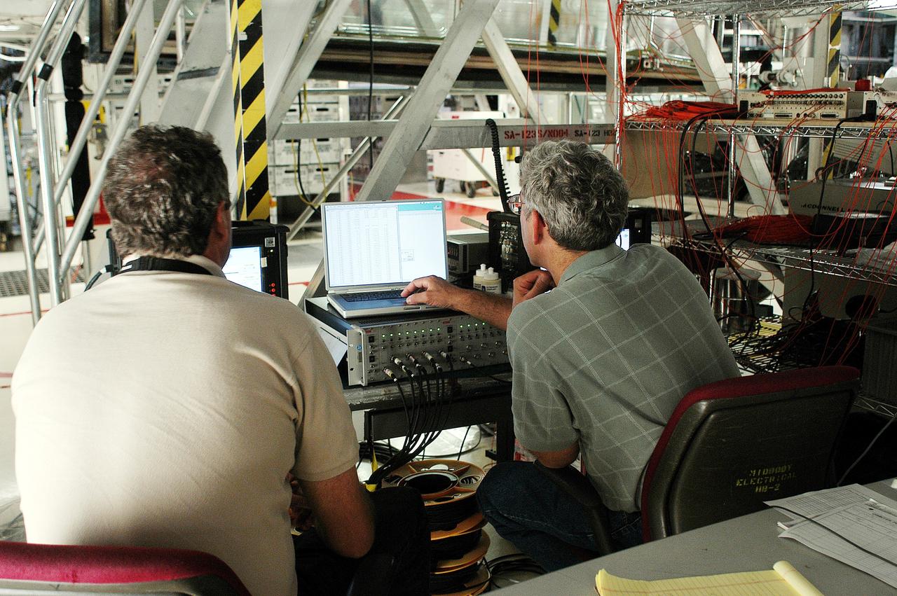
KENNEDY SPACE CENTER, FLA. - In the Orbiter Processing Facility, Bill Prosser (left) and Eric Madaras, NASA-Langley Research Center, conduct impulse tests on the right wing leading edge (WLE) of Space Shuttle Endeavour. The tests monitor how sound impulses propagate through the WLE area. The data collected will be analyzed to explore the possibility of adding new instrumentation to the wing that could automatically detect debris or micrometeroid impacts on the Shuttle while in flight. The study is part of the initiative ongoing at KSC and around the agency to return the orbiter fleet to flight status.
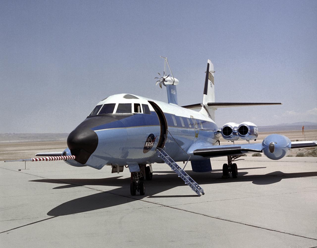
In this photo of the C-140 JetStar on the Dryden Ramp, a subscale propeller has been fitted to the upper fuselage of the aircraft.
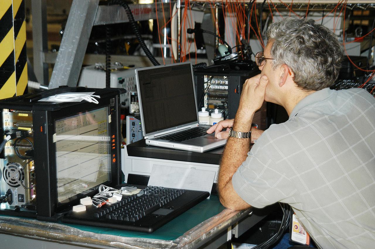
In the Orbiter Processing Facility, Eric Madaras, NASA-Langley Research Center, conducts impulse tests on the right wing leading edge (WLE) of Space Shuttle Endeavour. The tests monitor how sound impulses propagate through the WLE area. The data collected will be analyzed to explore the possibility of adding new instrumentation to the wing that could automatically detect debris or micrometeroid impacts on the Shuttle while in flight. The study is part of the initiative ongoing at KSC and around the agency to return the orbiter fleet to flight status.
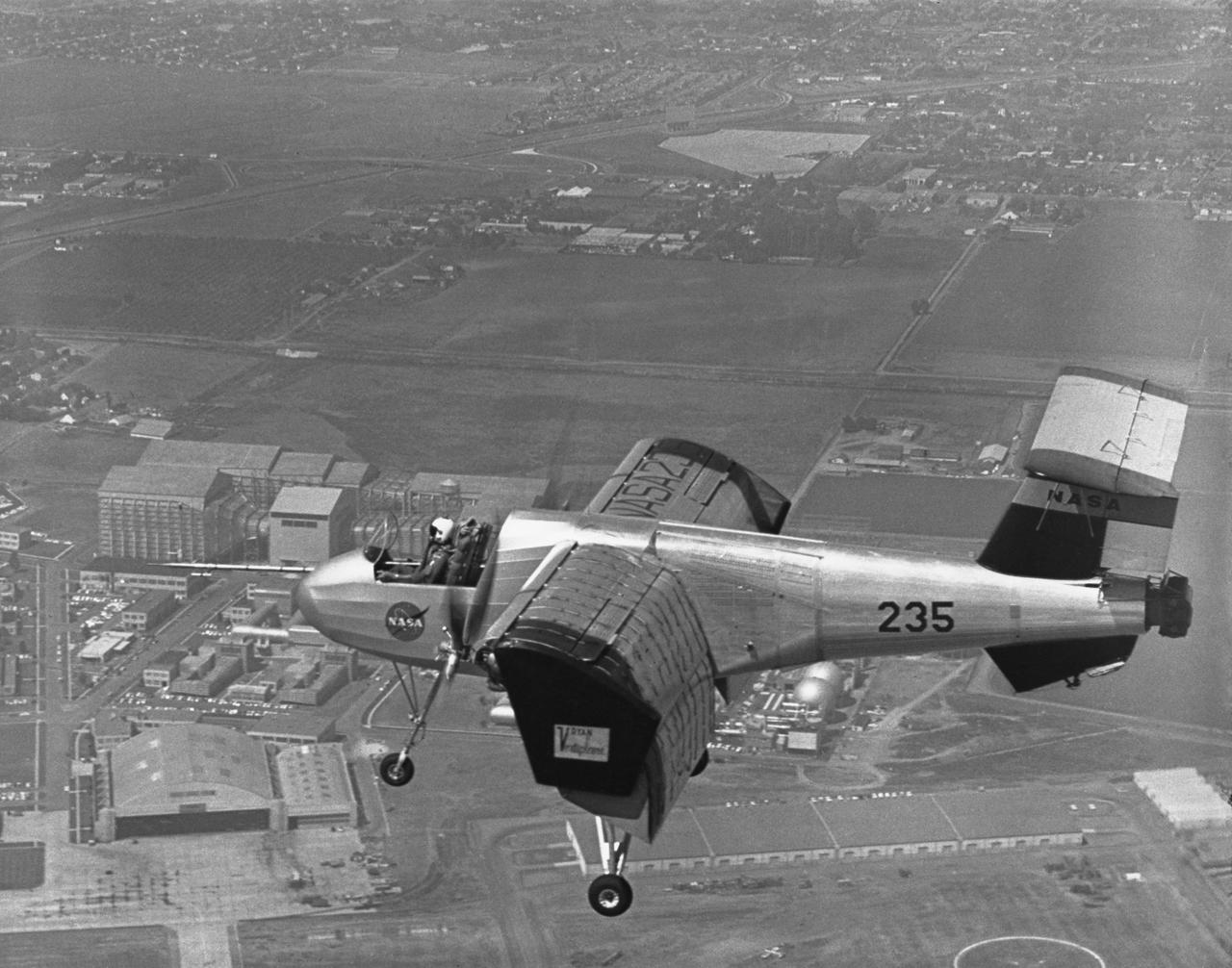
Ryan VZ-3RY over Ames in slow-speed flight. Smooth airflow over entire wing is indicated by tufts when wing had been modified to incorporate leading-edge slats. Tests showed that it could be flown at speeds as low as 6 knots when out of ground effect (which increases lift). April 1963 published in NASA SP-2002-4525 Memoirs of a Flight test Engineer (Seth Anderson)
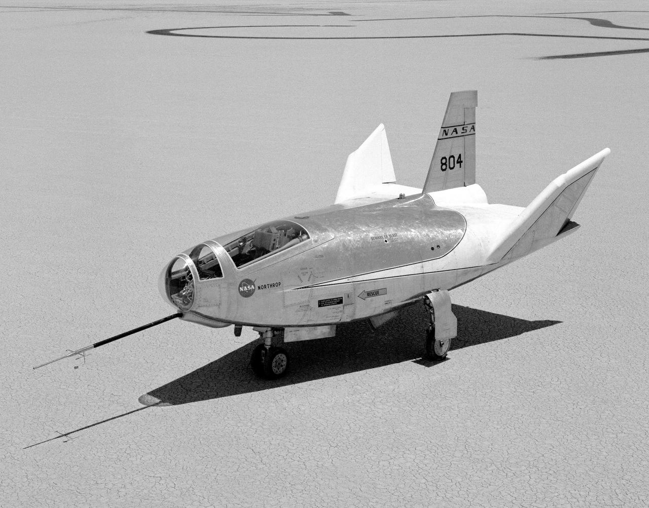
The HL-10 Lifting Body is seen here parked on Rogers Dry Lake, the unique location where it landed after research flights. This 1968 photo shows the vehicle after the fins were modified to remove instabilities encountered on the first flight. It involved a change to the shape of the leading edge of the fins to eliminate flow separation. It required extensive wind-tunnel testing at Langley Research Center, Hampton, Va. NASA Flight Research Center (FRC) engineer Bob Kempel than plotted thousands of data points by hand to come up with the modification, which involved a fiberglass glove backed with a metal structure on each fin's leading edge. This transformed the vehicle from a craft that was difficult to control into the best handling of the original group of lifting bodies at the FRC.
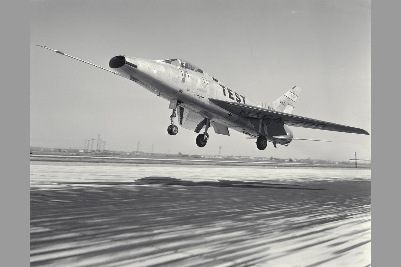
NACA Photographer North American F-100A (NACA-200) Super Sabre Airplane take-off. The blowing-tupe boundary-layer control on the leading- and trailing-edge provided large reductions in takeoff and landing approach speeds. Approach speeds were reduced by about 10 knots (Mar 1960). Note: Used in publication in Flight Research at Ames; 57 Years of Development and Validation of Aeronautical Technology NASA SP-1998-3300 fig. 102 and and Memoirs of a Flight Test Engneer NASA SP-2002-4525
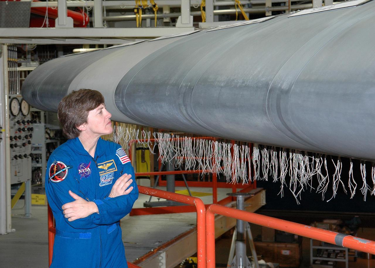
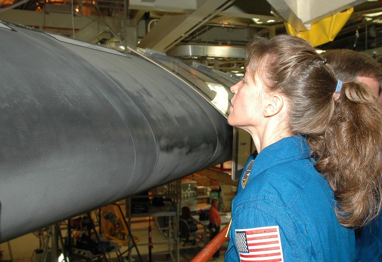
KENNEDY SPACE CENTER, FLA. - In the Orbiter Processing Facility, STS-114 Mission Specialist Wendy Lawrence looks closely at Discovery’s wing leading edge. The leading edge panels of the orbiters’ wings have 22 Reinforced Carbon-Carbon panels, made entirely of carbon composite material. The molded components are approximately 0.25-inch to 0.5-inch thick. Lawrence and other crew members are at KSC for Crew Equipment Interface Test activities. During CEIT, the crew has an opportunity to get a hands-on look at the orbiter and equipment they will be working with on the mission. Return to Flight Mission STS-114 will carry the Multi-Purpose Logistics Module Raffaello, filled with supplies for the International Space Station, and a replacement Control Moment Gyroscope. Launch of STS-114 has a launch window of May 12 to June 3.
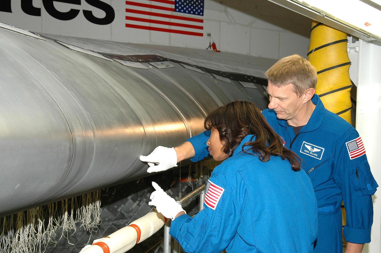
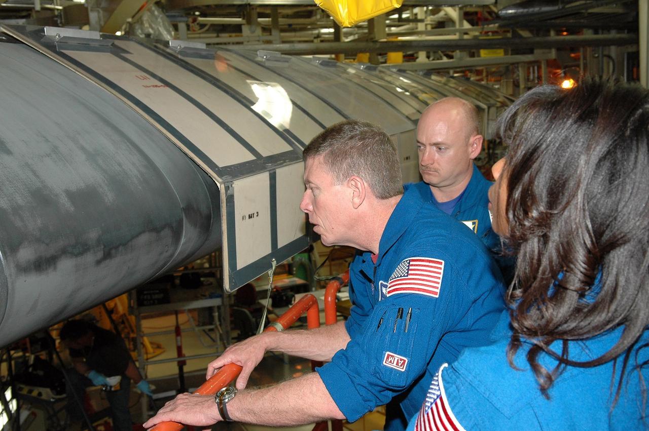
KENNEDY SPACE CENTER, FLA. - In the Orbiter Processing Facility, STS-121 Mission Specialists Stephanie D. Wilson (left) and Piers J. Sellers receive a briefing and up-close look at the wing leading edge of Space Shuttle Atlantis, the orbiter that will take them into space. The leading edge of each of the orbiters’ wings has 22 Reinforced Carbon-Carbon panels, made entirely of carbon composite material. The molded components are approximately 0.25-inch to 0.5-inch thick. The astronauts of the second Return to Flight mission, STS-121, are at Kennedy Space Center to participate in the Crew Equipment Interface Test (CEIT). During CEIT, the crew has an opportunity to get a hands-on look at the orbiter and equipment they will be working with on their mission. Mission STS-121 is scheduled to launch in July.
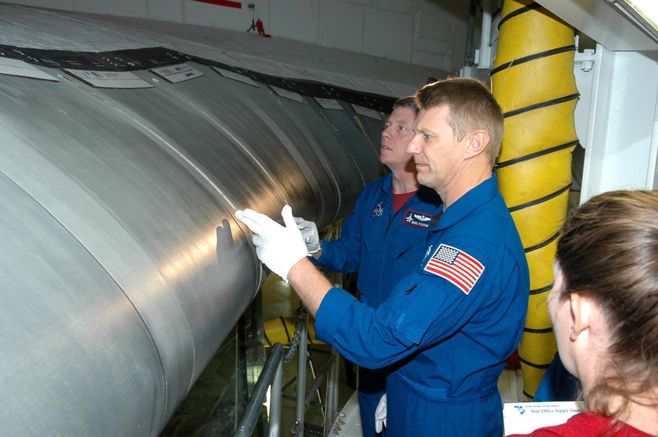
KENNEDY SPACE CENTER, FLA. - In the Orbiter Processing Facility, STS-121 Mission Specialists Michael E. Fossum (left) and Piers J. Sellers receive a briefing and up-close look at the wing leading edge of Space Shuttle Atlantis, the orbiter that will take them into space. The leading edge of each of the orbiters’ wings has 22 Reinforced Carbon-Carbon panels, made entirely of carbon composite material. The molded components are approximately 0.25-inch to 0.5-inch thick. The astronauts of the second Return to Flight mission, STS-121, are at Kennedy Space Center to participate in the Crew Equipment Interface Test (CEIT). During CEIT, the crew has an opportunity to get a hands-on look at the orbiter and equipment they will be working with on their mission. Mission STS-121 is scheduled to launch in July.
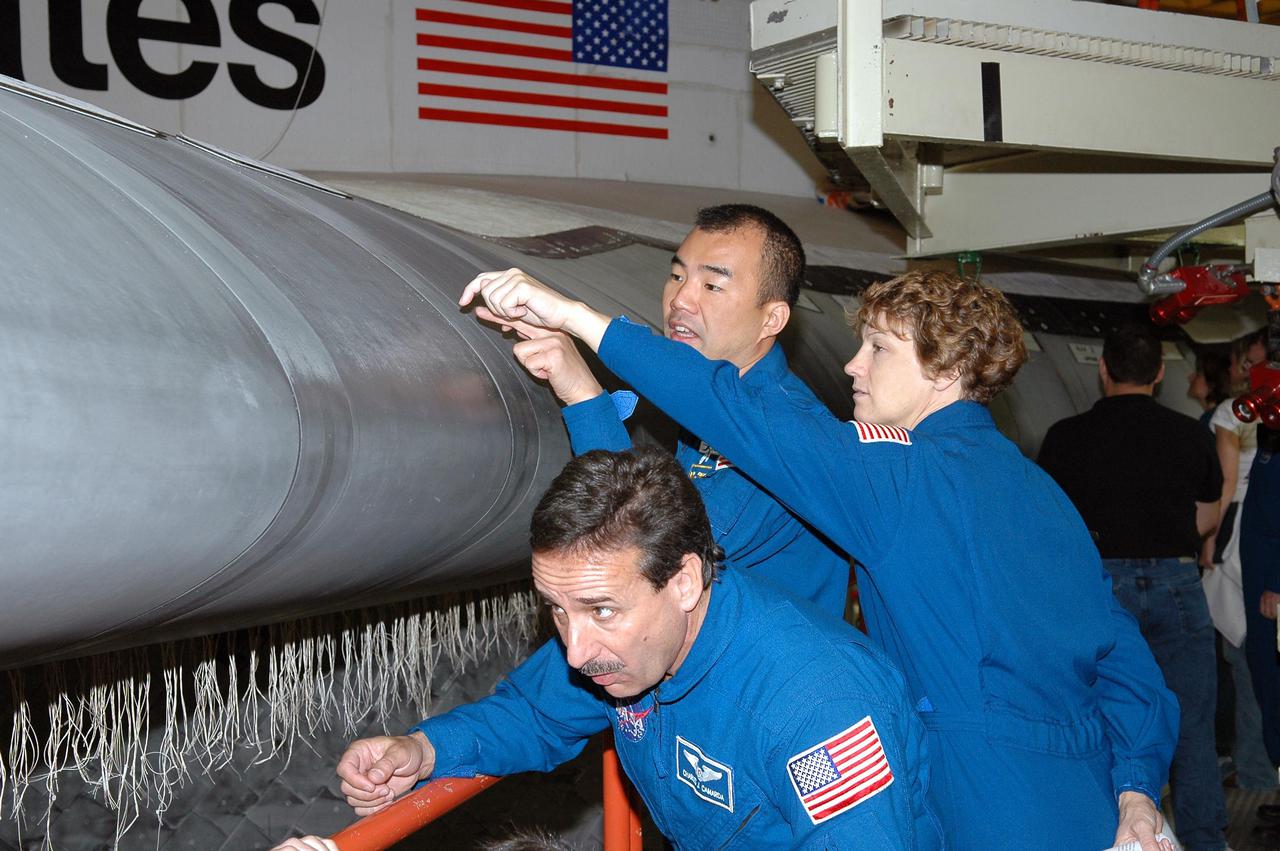
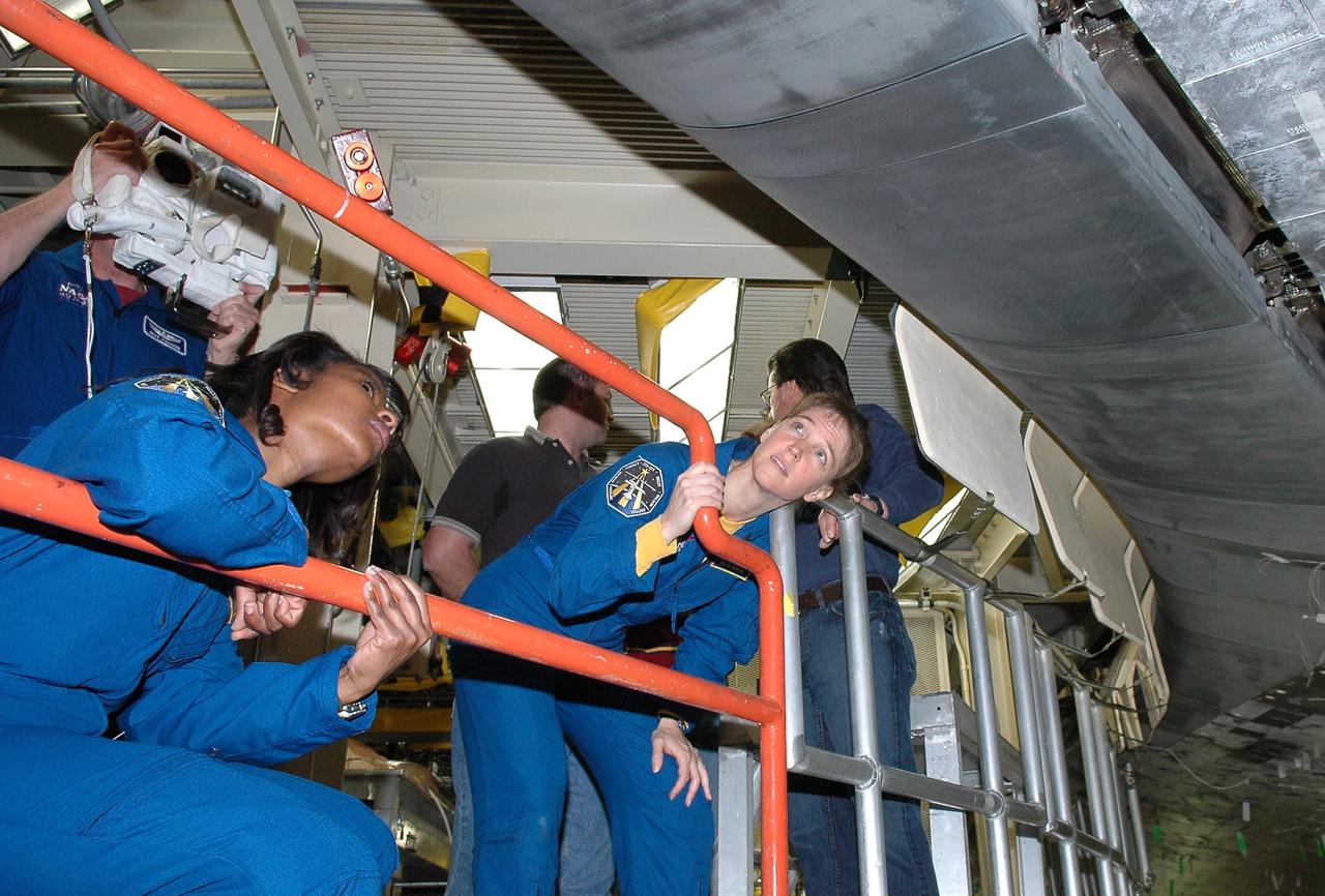
KENNEDY SPACE CENTER, FLA. - In the Orbiter Processing Facility, STS-114 Mission Specialist Charles Camarda looks under the wing leading edge on Discovery while Mission Specialist Soichi Noguchi and Commander Eileen Collins look at an area on top. They and other crew members are at KSC for Crew Equipment Interface Test activities. The leading edge panels of the orbiters’ wings have 22 Reinforced Carbon-Carbon panels, made entirely of carbon composite material. The molded components are approximately 0.25-inch to 0.5-inch thick. During CEIT, the crew has an opportunity to get a hands-on look at the orbiter and equipment they will be working with on the mission. Return to Flight Mission STS-114 will carry the Multi-Purpose Logistics Module Raffaello, filled with supplies for the International Space Station, and a replacement Control Moment Gyroscope. Launch of STS-114 has a launch window of May 12 to June 3.
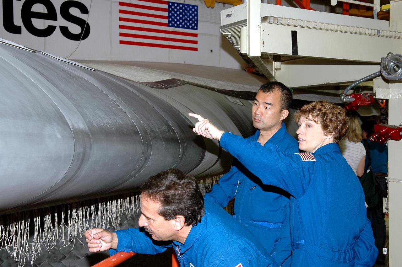
KENNEDY SPACE CENTER, FLA. - In the Orbiter Processing Facility, members of the STS-114 crew take a close look at the Reinforced Carbon-Carbon on the wing’s leading edge on Discovery. From left are Mission Specialists Charles Camarda and Soichi Noguchi (with the Japanese Space Agency), and Commander Eileen Collins. They and other crew members are at KSC for Crew Equipment Interface Test activities. The leading edge panels of the orbiters’ wings have 22 RCC panels, made entirely of carbon composite material. The molded components are approximately 0.25-inch to 0.5-inch thick. The leading edge panels of the orbiters’ wings have 22 Reinforced Carbon-Carbon panels, made entirely of carbon composite material. The molded components are approximately 0.25-inch to 0.5-inch thick. During CEIT, the crew has an opportunity to get a hands-on look at the orbiter and equipment they will be working with on the mission. Return to Flight Mission STS-114 will carry the Multi-Purpose Logistics Module Raffaello, filled with supplies for the International Space Station, and a replacement Control Moment Gyroscope. Launch of STS-114 has a launch window of May 12 to June 3.
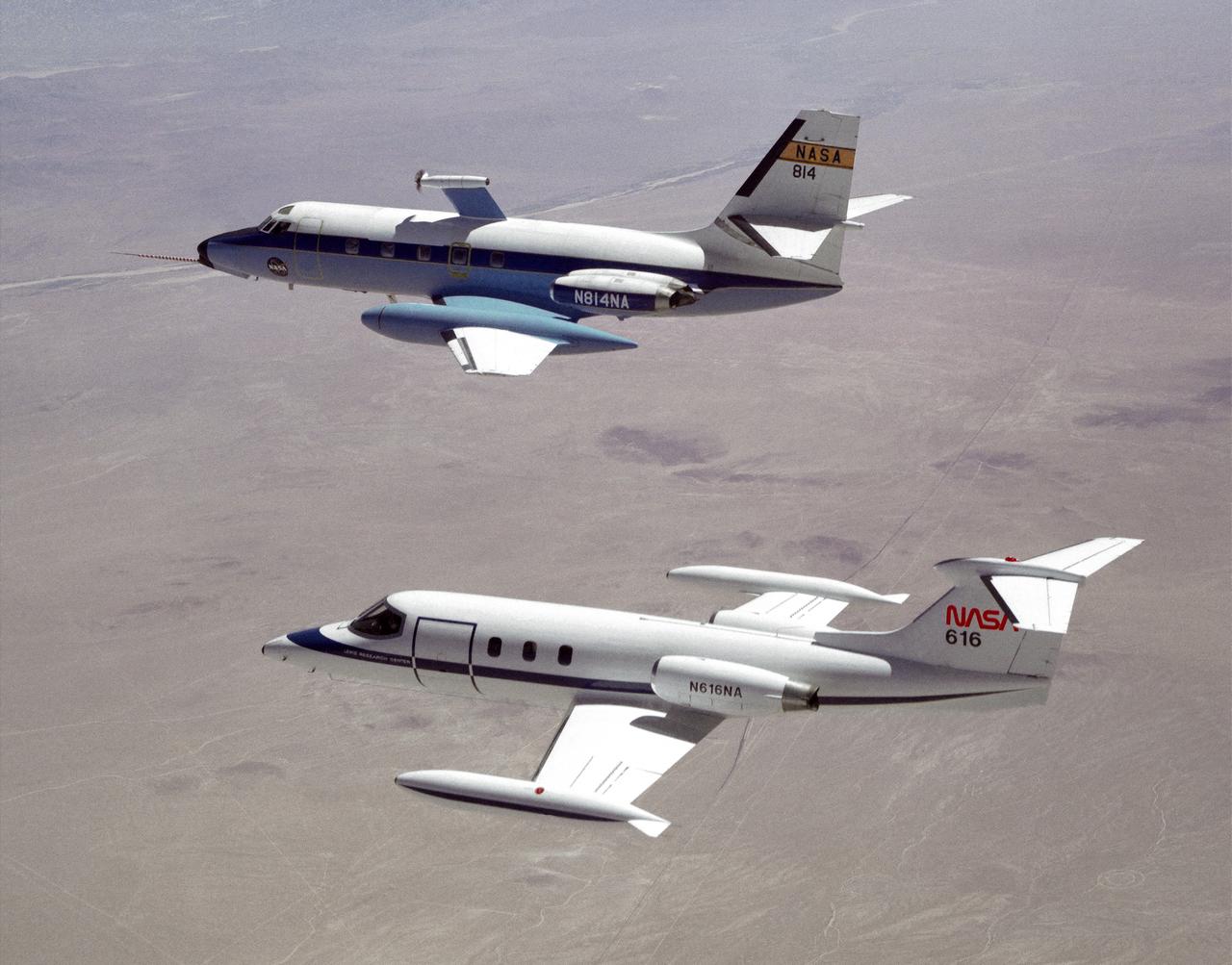
The NASA C-140 JetStar research aircraft (top) is followed by a NASA Learjet equipped with acoustic sensors during one of several tests of advanced propellors mounted on the vertical pylon atop the JetStar's fuselage. Several advanced prop designs were tested on the JetStar in 1982 by NASA's Dryden Flight Research Facility (DFRF), Edwards, California, to study the effects of noise created by propellors on aircraft structures and cabin interiors. To assess possible noise problems with the subscale turbofan, DFRF technicians mounted microphones on both the JetStar and the Learjet chase plane. DFRF then made measurements at close range and at longer distances. The data enabled structural changes and flightpath modifications.

DURING APPROACH. OGEE Wing Planform on modified F5D-1 SkylancerAirplane Flight Tests. 'Flow Visualization Photographs'. In landing approach trials at Moffett Field, vapor trails are generated by low pressure in votex flow near wing leading edge on upper wing surface. Studies were undertaken in efforts to determine if there were adverse effects of vortex flow on the dynamic stability of the aircraft.
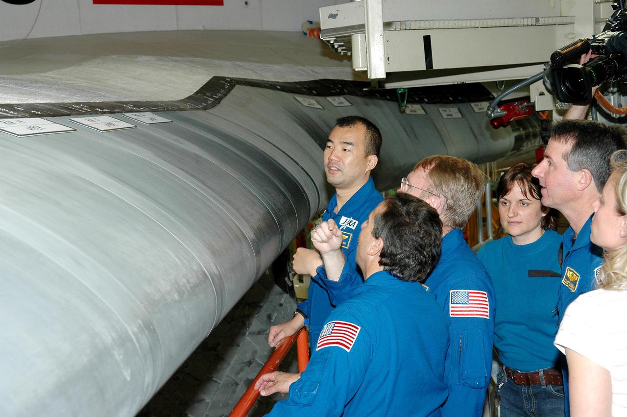
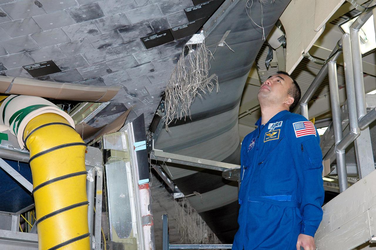
KENNEDY SPACE CENTER, FLA. - In the Orbiter Processing Facility, members of the STS-114 crew take a close look at the Reinforced Carbon-Carbon on the wing’s leading edge on Discovery. From left are Mission Specialists Soichi Noguchi (with the Japanese Space Agency), Charles Camarda and Andrew Thomas; accompanied by Cindy Begley, lead EVA flight controller. At right is Mission Specialist Stephen Robinson, with Christi Hansen, EVA trainer. The crew is at KSC for Crew Equipment Interface Test activities. The leading edge panels of the orbiters’ wings have 22 Reinforced Carbon-Carbon panels, made entirely of carbon composite material. The molded components are approximately 0.25-inch to 0.5-inch thick. During CEIT, the crew has an opportunity to get a hands-on look at the orbiter and equipment they will be working with on the mission. Return to Flight Mission STS-114 will carry the Multi-Purpose Logistics Module Raffaello, filled with supplies for the International Space Station, and a replacement Control Moment Gyroscope. Launch of STS-114 has a launch window of May 12 to June 3.
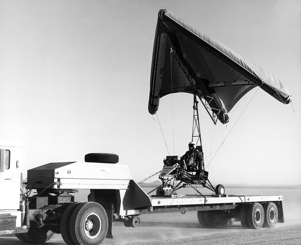
Aboard a truck and ready for a test flight is the Paresev 1-C on the ramp at the NASA Flight Research Center, Edwards, California. The half-scale version of the inflatable Gemini parawing was pre-flighted by being carried across the Rosamond dry lakebed on the back of a truck before a tow behind a International Harvester Carry-All. The inflatable center spar ran fore and aft and measured 191 inches, two other inflatable spars formed the leading edges. The three compartments were filled with nitrogen under pressure to make them rigid. The Paresev 1-C was very unstable in flight with this configuration.
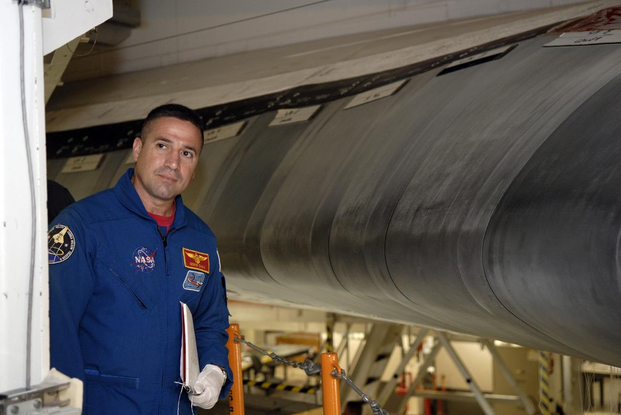
CAPE CANAVERAL, Fla. – In Orbiter Processing Facility-3 at NASA's Kennedy Space Center in Florida, STS-130 Commander George Zamka is briefed on the reinforced carbon carbon panels, part of the thermal protection system, on the leading edge of the wing of space shuttle Endeavour. The crew is at Kennedy for a crew equipment interface test, or CEIT, which provides hands-on training and observation of shuttle and flight hardware. The STS-130 flight will carry the Tranquility pressurized module with a built-in cupola to the International Space Station aboard Endeavour. Launch is targeted for Feb. 4, 2010. Photo credit: NASA/Kim Shiflett
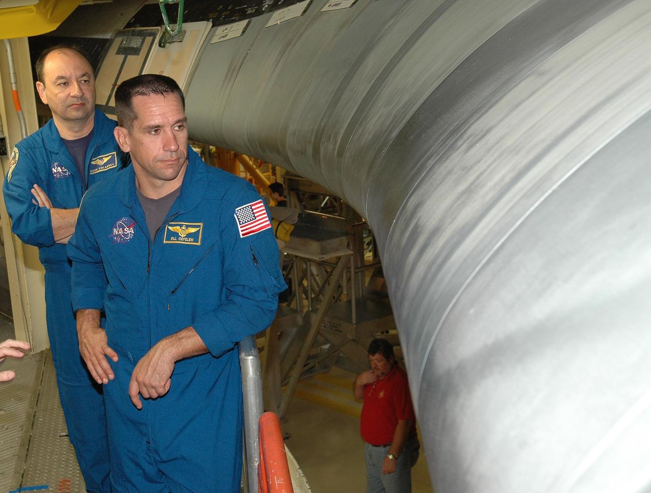
KENNEDY SPACE CENTER, FLA. - From a platform in the Orbiter Processing Facility, STS-116 Commander Mark Polansky (left) and Pilot William Oefelein look at one of Discovery’s reinforced carbon-carbon wing leading edge. They and other crew members are at KSC for a Crew Equipment Interface Test. Mission crews make frequent trips to the Kennedy Space Center to become familiar with the equipment and payloads they will be using. STS-116 will be mission No. 20 to the International Space Station and construction flight 12A.1. The mission payload is the SPACEHAB module, the P5 integrated truss structure and other key components. Launch is scheduled for no earlier than Dec. 7. Photo credit: NASA/Kim Shiflett
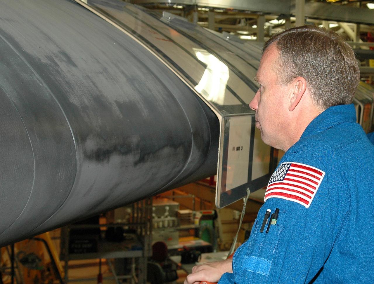
KENNEDY SPACE CENTER, FLA. - Inside the Orbiter Processing Facility bay 3 at NASA's Kennedy Space Center, STS-121 Commander Steven Lindsey gets a close look at the wing leading edge of Discovery, the launch vehicle for the mission. He and other crew members -- Pilot Mark Kelly and Mission Specialists Lisa Nowak, Stephanie Wilson, Michael Fossum and Piers Sellers -- are at Kennedy for a crew equipment interface test, which provides hands-on experience with equipment they will use on orbit. Launch of STS-121, the second return-to-flight mission, is scheduled for no earlier than May. Photo credit: NASA/Kim Shiflett
KENNEDY SPACE CENTER, FLA. - Inside the Orbiter Processing Facility bay 3 at NASA's Kennedy Space Center, STS-121 Mission Specialist Lisa Nowak and Commander Steven Lindsey take a close look at the wing leading edge of Discovery, the launch vehicle for the mission. They and other crew members -- Pilot Mark Kelly and Mission Specialists Stephanie Wilson, Michael Fossum and Piers Sellers -- are at Kennedy for a crew equipment interface test, which provides hands-on experience with equipment they will use on orbit. Launch of STS-121, the second return-to-flight mission, is scheduled for no earlier than May. Photo credit: NASA/Kim Shiflett
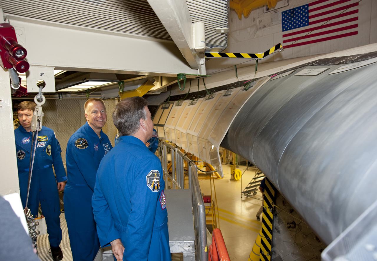
CAPE CANAVERAL, Fla. -- In Orbiter Processing Facility-3 at NASA's Kennedy Space Center in Florida, STS-133 Commander examines the shuttle's wing leading edge while Mission Specialist Tim Kopra and Michael Barratt look on. The astronauts are at Kennedy for the Crew Equipment Interface Test, or CEIT, which provides the crew with hands-on training and observation of shuttle and flight hardware for their mission to the International Space Station. Launch of the STS-133 mission on space shuttle Discovery is targeted for Nov. 1 at 4:33 p.m. EDT. Photo credit: NASA_Kim Shiflett
KENNEDY SPACE CENTER, FLA. - Inside the Orbiter Processing Facility bay 3 at NASA's Kennedy Space Center, STS-121 Mission Specialist Lisa Nowak gets a close look at the wing leading edge of Discovery, the launch vehicle for the mission. She and other crew members -- Commander Steven Lindsey, Pilot Mark Kelly and Mission Specialists Stephanie Wilson, Michael Fossum and Piers Sellers -- are at Kennedy for a crew equipment interface test, which provides hands-on experience with equipment they will use on orbit. Launch of STS-121, the second return-to-flight mission, is scheduled for no earlier than May. Photo credit: NASA/Kim Shiflett
KENNEDY SPACE CENTER, FLA. - Inside the Orbiter Processing Facility bay 3 at NASA's Kennedy Space Center, members of the STS-121 crew get a close look at the wing leading edge of Discovery, the launch vehicle for the mission. Seen here are Mission Specialist Michael Fossum, Pilot Mark Kelly and Mission Specialist Stephanie Nowak. They and other crew members -- Commander Steven Lindsey and Mission Specialists Lisa Nowak and Piers Sellers -- are at Kennedy for a crew equipment interface test, which provides hands-on experience with equipment they will use on orbit. Launch of STS-121, the second return-to-flight mission, is scheduled for no earlier than May. Photo credit: NASA/Kim Shiflett
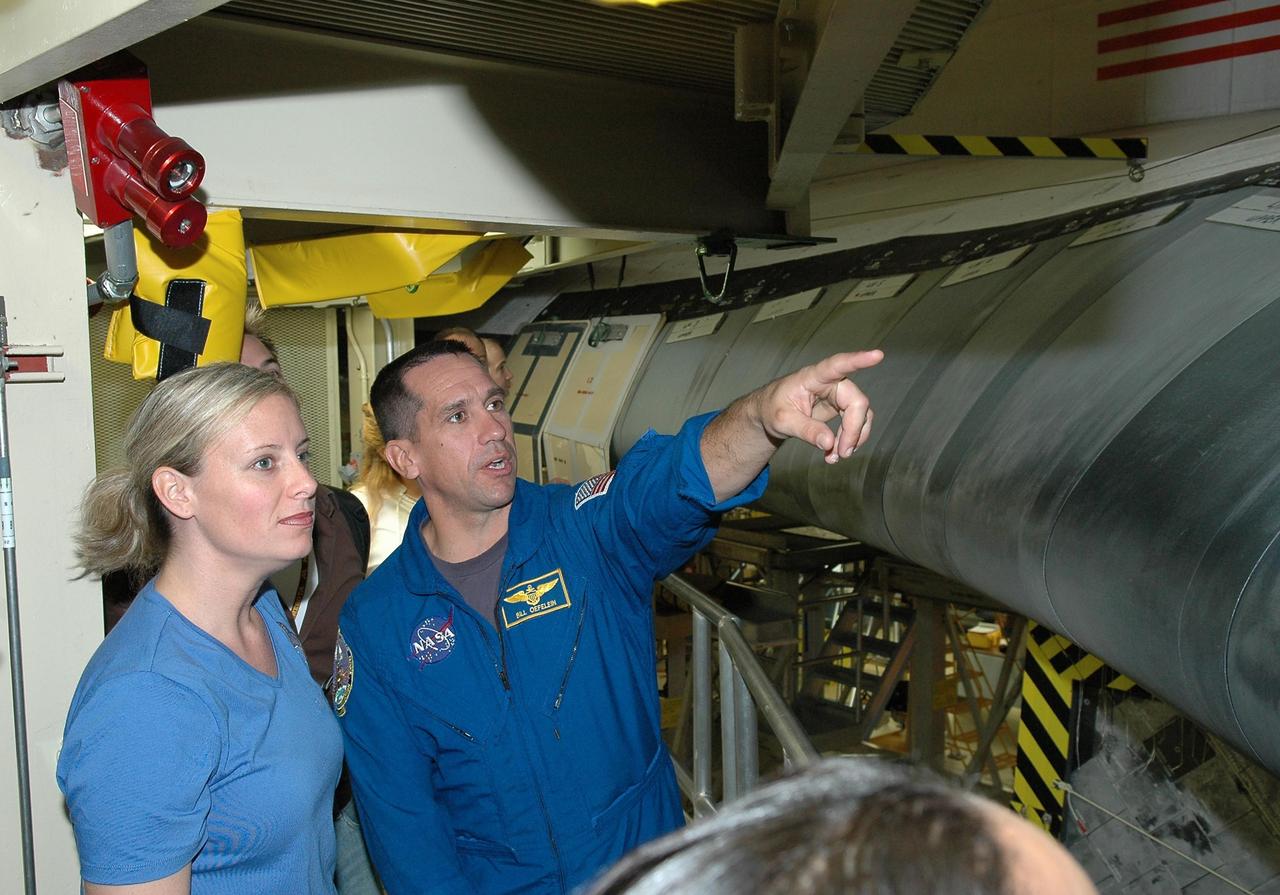
KENNEDY SPACE CENTER, FLA. - From a platform in the Orbiter Processing Facility, STS-116 Pilot William Oefelein points to Discovery’s reinforced carbon-carbon wing leading edge. He and other crew members are at KSC for a Crew Equipment Interface Test. Mission crews make frequent trips to the Kennedy Space Center to become familiar with the equipment and payloads they will be using. STS-116 will be mission No. 20 to the International Space Station and construction flight 12A.1. The mission payload is the SPACEHAB module, the P5 integrated truss structure and other key components. Launch is scheduled for no earlier than Dec. 7. Photo credit: NASA/Kim Shiflett
KENNEDY SPACE CENTER, FLA. - In the Orbiter Processing Facility, STS-114 Mission Specialist Soichi Noguchi (with the Japanese Space Agency) looks closely at the Reinforced Carbon-Carbon panel on Discovery’s wing leading edge. The panels are part of the Thermal Protection System on the orbiter. Noguchi and other crew members are at KSC for Crew Equipment Interface Test activities. During CEIT, the crew has an opportunity to get a hands-on look at the orbiter and equipment they will be working with on the mission. Return to Flight Mission STS-114 will carry the Multi-Purpose Logistics Module Raffaello, filled with supplies for the International Space Station, and a replacement Control Moment Gyroscope. Launch of STS-114 has a launch window of May 12 to June 3.

CAPE CANAVERAL, Fla. - In Orbiter Processing Facility 3 at NASA's Kennedy Space Center in Florida, members of space shuttle Discovery's STS-131 crew participate in training activities during the Crew Equipment Interface Test, or CEIT, for their mission. Here, from left in the blue flight suits, Mission Specialists Naoko Yamazaki of the Japan Aerospace Exploration Agency and Dorothy Metcalf-Lindenburger, and Commander Alan Poindexter get a close look at the reinforced carbon carbon panels on Discovery's wing leading edge, part of the shuttle's thermal protection system. The CEIT provides the crew with hands-on training and observation of shuttle and flight hardware. The seven-member crew will deliver the multi-purpose logistics module Leonardo, filled with resupply stowage platforms and racks to be transferred to locations around the International Space Station. Three spacewalks will include work to attach a spare ammonia tank assembly to the station's exterior and return a European experiment from outside the station's Columbus module. Discovery's launch is targeted for March 18. For information on the STS-131 mission and crew, visit http://www.nasa.gov/mission_pages/shuttle/shuttlemissions/sts131/index.html. Photo credit: NASA/Kim Shiflett
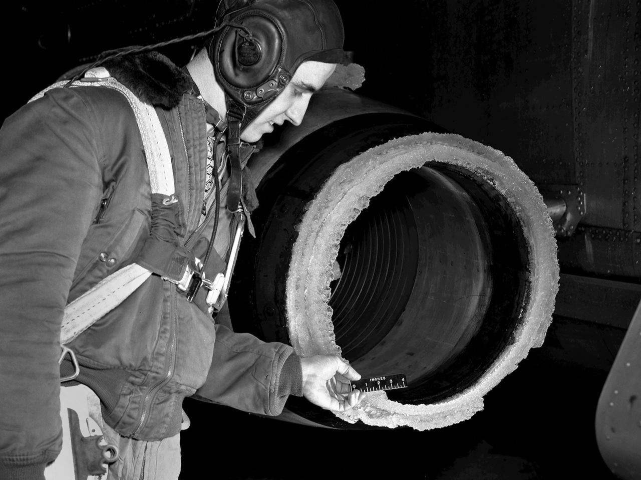
The National Advisory Committee for Aeronautics (NACA) Lewis Flight Propulsion Laboratory conducted an extensive icing research program in the late 1940s that included studies in the Icing Research Tunnel and using specially modified aircraft. One facet of this program was the investigation of the effects of icing on turbojets. Although jet engines allowed aircraft to pass through inclement weather at high rates of speed, ice accumulation was still a concern. The NACA’s B-24M Liberator was initially reconfigured with a General Electric I-16 engine installed in the aircraft’s waist compartment with an air scoop and spray nozzles to produce the artificial icing conditions. The centrifugal engine appeared nearly impervious to the effects of icing. Axial-flow jet engines, however, were much more susceptible to icing damage. The inlet guide vanes were particularly vulnerable, but the cowling’s leading edge, the main bearing supports, and accessory housing could also ice up. If pieces of ice reached the engine’s internal components, the compressor blades could be damaged. To study this phenomenon, a Westinghouse 24C turbojet, seen in this photograph, was installed under the B-24M’s right wing. In January 1948 flight tests of the 24C in icing conditions began. Despite ice buildup into the second stage of the compressor, the engine was able to operate at takeoff speeds. Researchers found the ice on the inlet vanes resulted in half of the engine’s decreased performance.
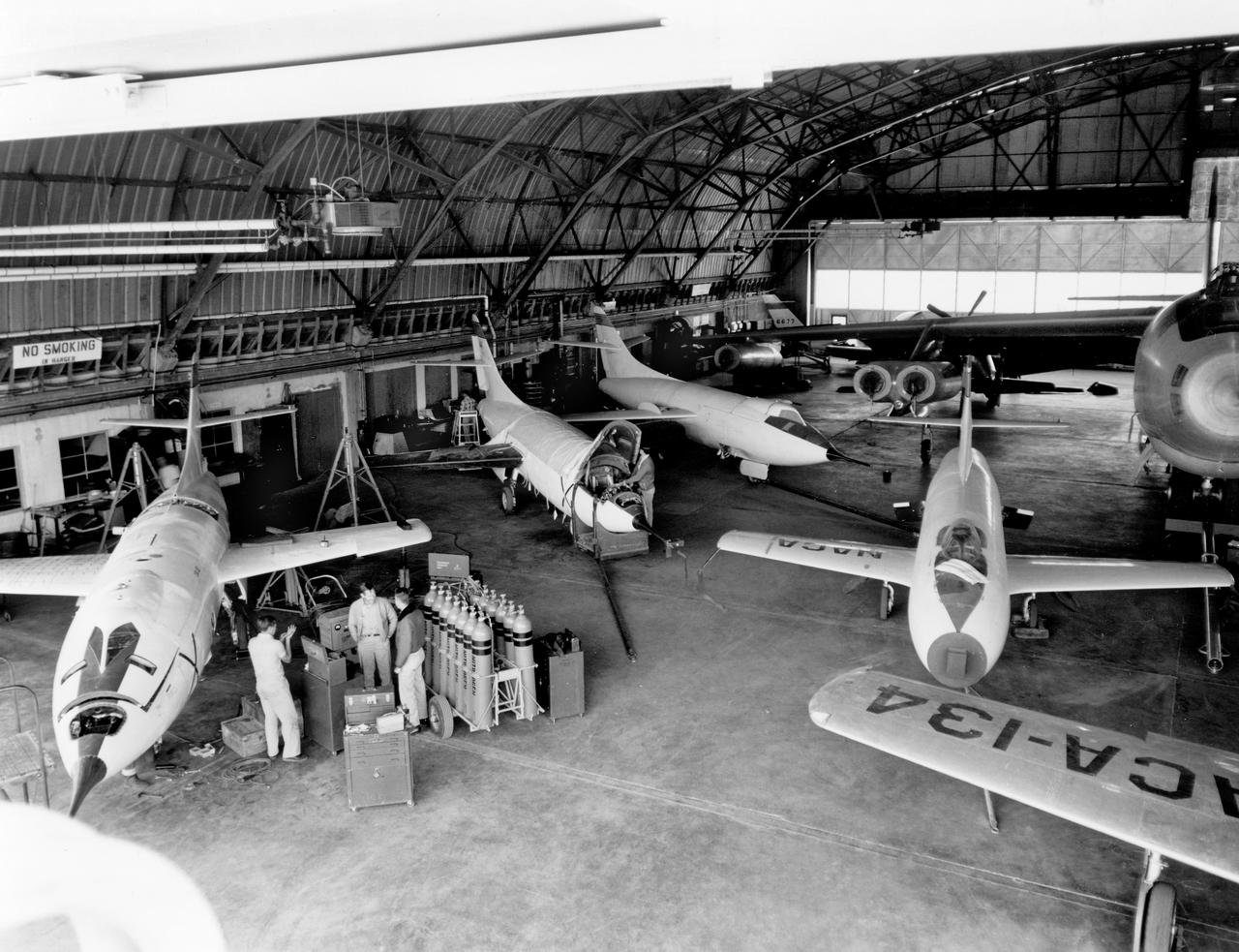
The aircraft in this 1953 photo of the National Advisory Committee for Aeronautics (NACA) hangar at South Base of Edwards Air Force Base showed the wide range of research activities being undertaken. On the left side of the hangar are the three D-558-2 research aircraft. These were designed to test swept wings at supersonic speeds approaching Mach 2. The front D-558-2 is the third built (NACA 145/Navy 37975). It has been modified with a leading-edge chord extension. This was one of a number of wing modifications, using different configurations of slats and/or wing fences, to ease the airplane's tendency to pitch-up. NACA 145 had both a jet and a rocket engine. The middle aircraft is NACA 144 (Navy 37974), the second built. It was all-rocket powered, and Scott Crossfield made the first Mach 2 flight in this aircraft on November 20, 1953. The aircraft in the back is D-558-2 number 1. NACA 143 (Navy 37973) was also carried both a jet and a rocket engine in 1953. It had been used for the Douglas contractor flights, then was turned over to the NACA. The aircraft was not converted to all-rocket power until June 1954. It made only a single NACA flight before NACA's D-558-2 program ended in 1956. Beside the three D-558-2s is the third D-558-1. Unlike the supersonic D-558-2s, it was designed for flight research at transonic speeds, up to Mach 1. The D-558-1 was jet-powered, and took off from the ground. The D-558-1's handling was poor as it approached Mach 1. Given the designation NACA 142 (Navy 37972), it made a total of 78 research flights, with the last in June 1953. In the back of the hangar is the X-4 (Air Force 46-677). This was a Northrop-built research aircraft which tested a swept wing design without horizontal stabilizers. The aircraft proved unstable in flight at speeds above Mach 0.88. The aircraft showed combined pitching, rolling, and yawing motions, and the design was considered unsuitable. The aircraft, the second X-4 built, was then used as a pilot traine

An artist's rendering of the air-breathing, hypersonic X-43B, the third and largest of NASA's Hyper-X series flight demonstrators, which could fly later this decade. Revolutionizing the way we gain access to space is NASA's primary goal for the Hypersonic Investment Area, managed for NASA by the Advanced Space Transportation Program at the Marshall Space Flight Center in Huntsville, Alabama. The Hypersonic Investment area, which includes leading-edge partners in industry and academia, will support future generation reusable vehicles and improved access to space. These technology demonstrators, intended for flight testing by decade's end, are expected to yield a new generation of vehicles that routinely fly about 100,000 feet above Earth's surface and reach sustained speeds in excess of Mach 5 (3,750 mph), the point at which "supersonic" flight becomes "hypersonic" flight. The flight demonstrators, the Hyper-X series, will be powered by air-breathing rocket or turbine-based engines, and ram/scramjets. Air-breathing engines, known as combined-cycle systems, achieve their efficiency gains over rocket systems by getting their oxygen for combustion from the atmosphere, as opposed to a rocket that must carry its oxygen. Once a hypersonic vehicle has accelerated to more than twice the speed of sound, the turbine or rockets are turned off, and the engine relies solely on oxygen in the atmosphere to burn fuel. When the vehicle has accelerated to more than 10 to 15 times the speed of sound, the engine converts to a conventional rocket-powered system to propel the craft into orbit or sustain it to suborbital flight speed. NASA's series of hypersonic flight demonstrators includes three air-breathing vehicles: the X-43A, X-43B and X-43C.
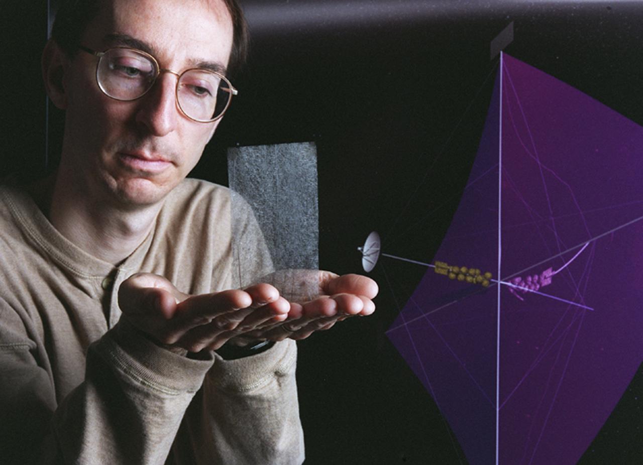
Engineers at Marshall Space Flight Center's (MSFC) Interstellar Propulsion Research department are proposing different solutions to combustion propellants for future space travel. One alternative being tested is the solar sail. The idea is, once deployed, the sail will allow solar winds to propel a spacecraft away from Earth and towards its destination. This would allow a spacecraft to travel indefinitely without the need to refuel during its ong journey. Thin reflective sails could be propelled through space by sunlight, microwave beams, or laser beams, just as the wind pushes sailboats on Earth. The sail will be the largest spacecraft ever built, sparning 440 yards, twice the diameter of the Louisiana Super Dome. Construction materials are being tested in a simulated space environment, where they are exposed to harsh conditions to test their performance and durability in extremely hot and cold temperatures. A leading candidate for the construction material is a carbon fiber material whose density is less than 1/10 ounce per square yard, the equivalent of flattening one raisin to the point that it covers a square yard. In space, the material would unfurl like a fan when it is deployed from an expendable rocket. This photo shows Les Johnson, manager of MSFC's Interstellar Propulsion Research Center holding the rigid, lightweight carbon fiber. An artist's concept of the sail is on the right. Mankind's first venture outside of our solar system is proposed for launch in a 2010 timeframe. An interstellar probe, powered by the fastest spacecraft ever flown, will zoom toward the stars at 58 miles per second. It will cover the distance from New York to Los Angeles in less than a minute and will travel over 23 billion miles beyond the edge of the solar system.
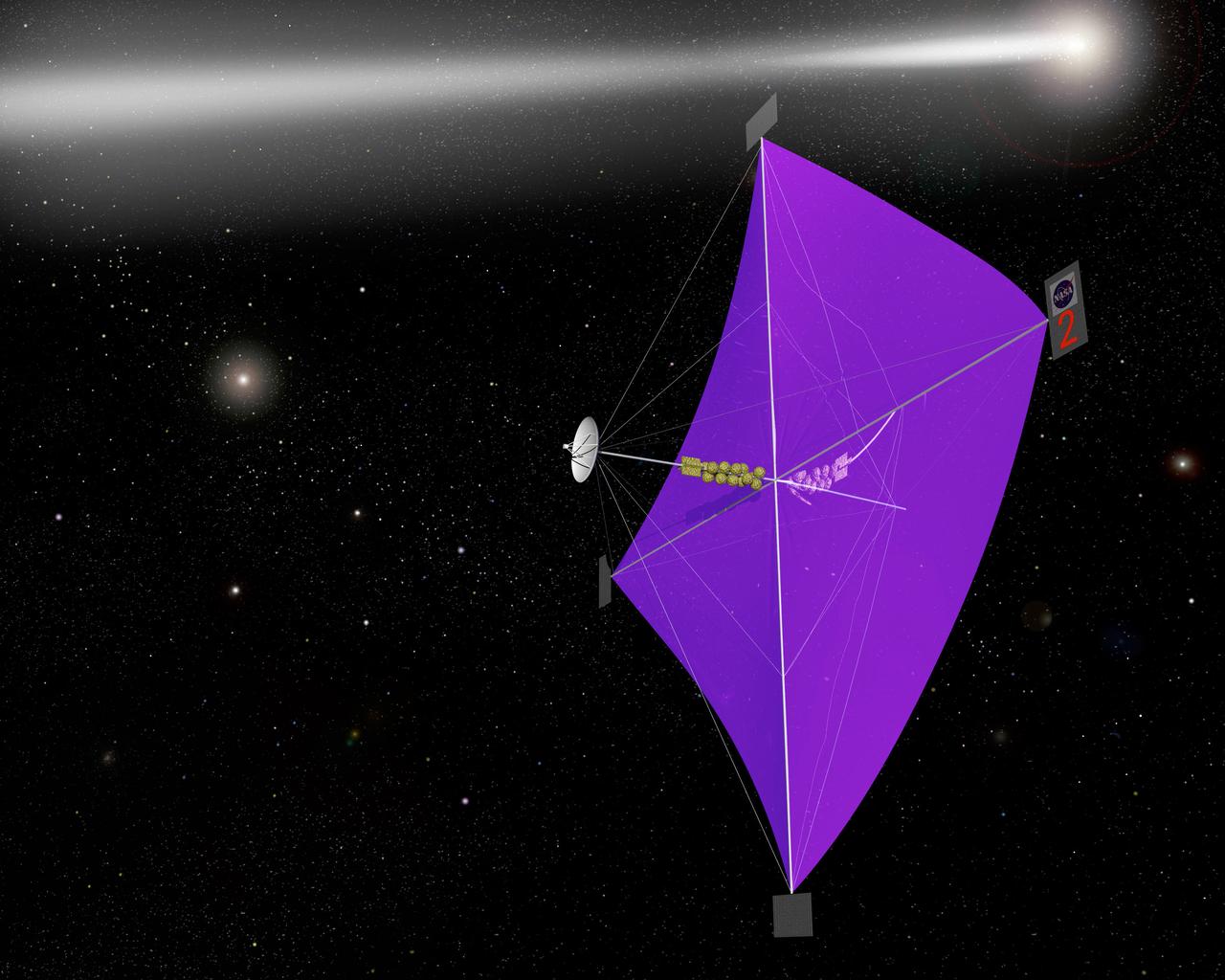
Engineers at Marshall Space Flight Center's Interstellar Propulsion Research department are proposing different solutions to combustion propellants for future space travel. Pictured here is one alternative, the solar sail, depicted through an artist's concept. The idea is, once deployed, the sail will allow solar winds to propel a spacecraft away from Earth and towards its destination. This would allow a spacecraft to travel indefinitely without the need to refuel during its prolong journey. Thin reflective sails could be propelled through space by sunlight, microwave beams, or laser beams, just as the wind pushes sailboats on Earth. The sail will be the largest spacecraft ever built, sparning 440 yards, twice the diameter of the Louisiana Super Dome. Construction materials are being tested in a simulated space environment, where they are exposed to harsh conditions to test their performance and durability in extremely hot and cold temperatures. A leading candidate for the construction material is a carbon fiber material whose density is less than 1/10 ounce per square yard, the equivalent of flattening one raisin to the point that it covers a square yard. In space, the material would unfurl like a fan when it is deployed from an expendable rocket. Mankind's first venture outside of our solar system is proposed for launch in a 2010 timeframe. An interstellar probe, powered by the fastest spacecraft ever flown, will zoom toward the stars at 58 miles per second. It will cover the distance from New York to Los Angeles in less than a minute and will travel over 23 billion miles beyond the edge of the solar system.
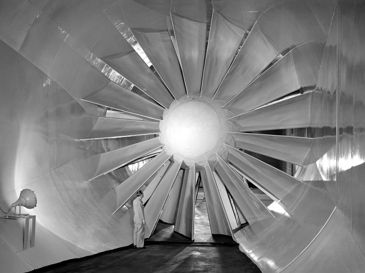
A researcher examines the drive fan inside the Icing Research Tunnel at the National Advisory Committee for Aeronautics (NACA) Flight Propulsion Research Laboratory in Cleveland, Ohio. The facility was built in the mid-1940s to simulate the atmospheric conditions that caused ice to build up on aircraft. Carrier Corporation refrigeration equipment reduced the internal air temperature to -45⁰ F, and a spray bar system injected water droplets into the air stream. The 24-foot diameter drive fan, seen in this photograph, created air flow velocities up to 400 miles per hour. The 1950s were prime years for the Icing Research Tunnel. NACA engineers had spent the 1940s trying to resolve the complexities of the spray bar system. The final system put into operation in 1950 included six horizontal spray bars with 80 nozzles that produced a 4- by 4-foot cloud in the test section. The icing tunnel was used for extensive testing of civilian and military aircraft components in the 1950s. The NACA also launched a major investigation of the various methods of heating leading edge surfaces. The hot-air anti-icing technology used on today’s commercial transports was largely developed in the facility during this period. Lewis researchers also made significant breakthroughs with icing on radomes and jet engines. Although the Icing Research Tunnel yielded major breakthroughs in the 1950s, the Lewis icing research program began tapering off as interest in the space program grew. The icing tunnel’s use declined in 1956 and 1957. The launch of Sputnik in October 1957 signaled the end of the facility’s operation. The icing staff was transferred to other research projects and the icing tunnel was temporarily mothballed.
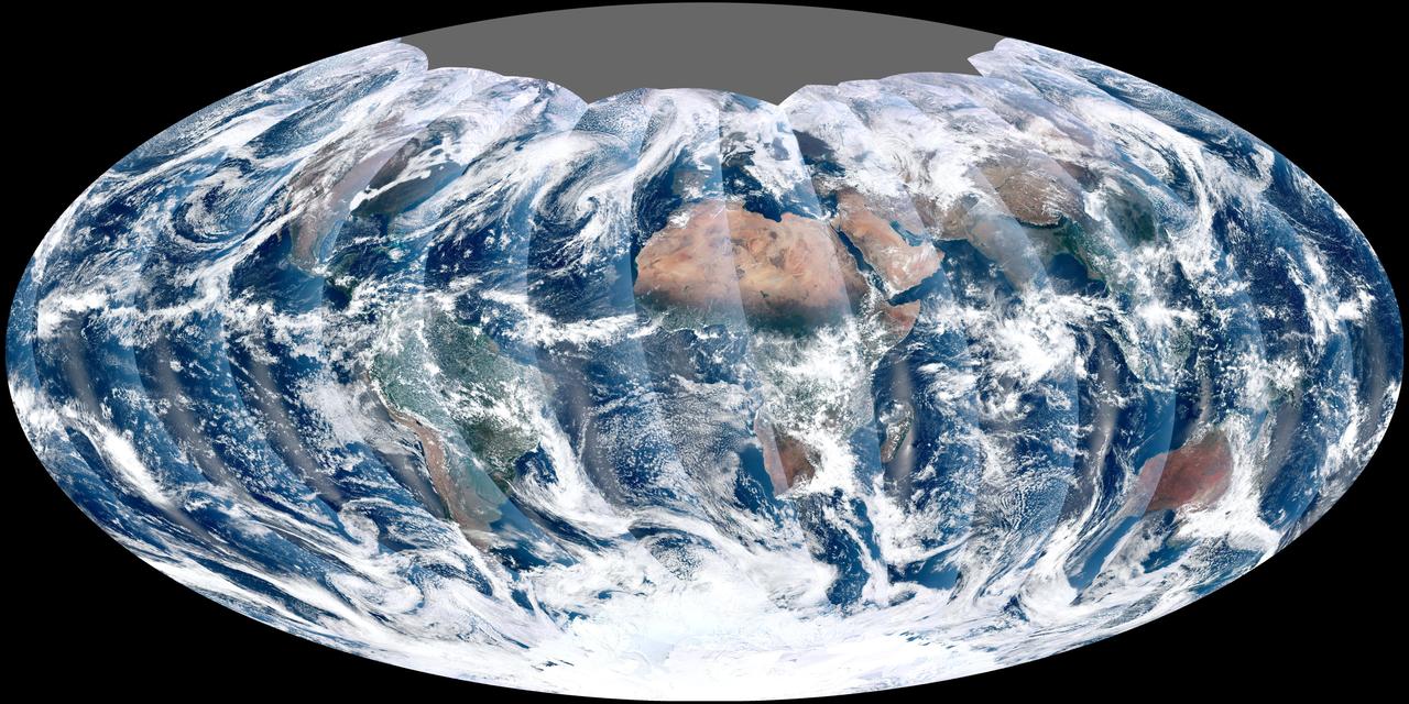
NASA acquired November 24, 2011 From its vantage 824 kilometers (512 miles) above Earth, the Visible Infrared Imager Radiometer Suite (VIIRS) on the NPOESS Preparatory Project (NPP) satellite gets a complete view of our planet every day. This image from November 24, 2011, is the first complete global image from VIIRS. The NPP satellite launched on October 28, 2011, and VIIRS acquired its first measurements on November 21. To date, the images are preliminary, used to gauge the health of the sensor as engineers continue to power it up for full operation. Rising from the south and setting in the north on the daylight side of Earth, VIIRS images the surface in long wedges measuring 3,000 kilometers (1,900 miles) across. The swaths from each successive orbit overlap one another, so that at the end of the day, the sensor has a complete view of the globe. The Arctic is missing because it is too dark to view in visible light during the winter. The NPP satellite was placed in a Sun-synchronous orbit, a unique path that takes the satellite over the equator at the same local (ground) time in every orbit. So, when NPP flies over Kenya, it is about 1:30 p.m. on the ground. When NPP reaches Gabon—about 3,000 kilometers to the west—on the next orbit, it is close to 1:30 p.m. on the ground. This orbit allows the satellite to maintain the same angle between the Earth and the Sun so that all images have similar lighting. The consistent lighting is evident in the daily global image. Stripes of sunlight (sunglint) reflect off the ocean in the same place on the left side of every swath. The consistent angle is important because it allows scientists to compare images from year to year without worrying about extreme changes in shadows and lighting. The image also shows a band of haze along the right side of every orbit swath. When light travels through the atmosphere, it bounces off particles or scatters, making the atmosphere look hazy. The scattering effect is most pronounced along the edge of the swath, where the sensor is looking at an angle through more of the atmosphere. Scientists can correct for this scattering effect, but need measurements from a range of wavelengths to do so. The degree to which light scatters depends partly on the wavelength of the light. Blue light scatters more than red light, for example, which is why the sky is blue. VIIRS measures 22 different wavelengths of light, but not all of the sensor’s detectors are operating at peak performance yet. Those measuring thermal infrared light are not yet cold enough to collect reliable measurements. Once VIIRS begins full operations, it will produce a range of measurements from ocean temperature to clouds to the locations of fires. These measurements will help extend the record from earlier sensors like the Moderate Resolution Imaging Spectroradiometer (MODIS). VIIRS is very similar to MODIS, but flies at a higher altitude to measure the whole planet without gaps. (MODIS daily measurements have gaps at the equator. See the MODIS image from November 24.) VIIRS also sees the Earth in less detail, 375 meters per pixel, compared to 250 meters per pixel for MODIS. Image by NASA’s NPP Land Product Evaluation and Testing Element. Caption by Holli Riebeek. Credit: <b><a href="http://www.earthobservatory.nasa.gov/" rel="nofollow"> NASA Earth Observatory</a></b> <b><a href="http://www.nasa.gov/audience/formedia/features/MP_Photo_Guidelines.html" rel="nofollow">NASA image use policy.</a></b> <b><a href="http://www.nasa.gov/centers/goddard/home/index.html" rel="nofollow">NASA Goddard Space Flight Center</a></b> enables NASA’s mission through four scientific endeavors: Earth Science, Heliophysics, Solar System Exploration, and Astrophysics. Goddard plays a leading role in NASA’s accomplishments by contributing compelling scientific knowledge to advance the Agency’s mission. <b>Follow us on <a href="http://twitter.com/NASA_GoddardPix" rel="nofollow">Twitter</a></b> <b>Like us on <a href="http://www.facebook.com/pages/Greenbelt-MD/NASA-Goddard/395013845897?ref=tsd" rel="nofollow">Facebook</a></b> <b>Find us on <a href="http://instagrid.me/nasagoddard/?vm=grid" rel="nofollow">Instagram</a></b>