Curved Confocal Lightweight Antenna Structures for Aeronautical Communications Technologies, CLAS-ACT, Phased Array Antenna on Mock Carbon Fiber Fuselage
Curved Confocal Lightweight Antenna Structures for Aeronautical Communications Technologies, CLAS-ACT, Phased Array Antenna on Mock Carbon Fiber Fuselage
Curved Confocal Lightweight Antenna Structures for Aeronautical Communications Technologies, CLAS-ACT, Phased Array Antenna on Mock Carbon Fiber Fuselage
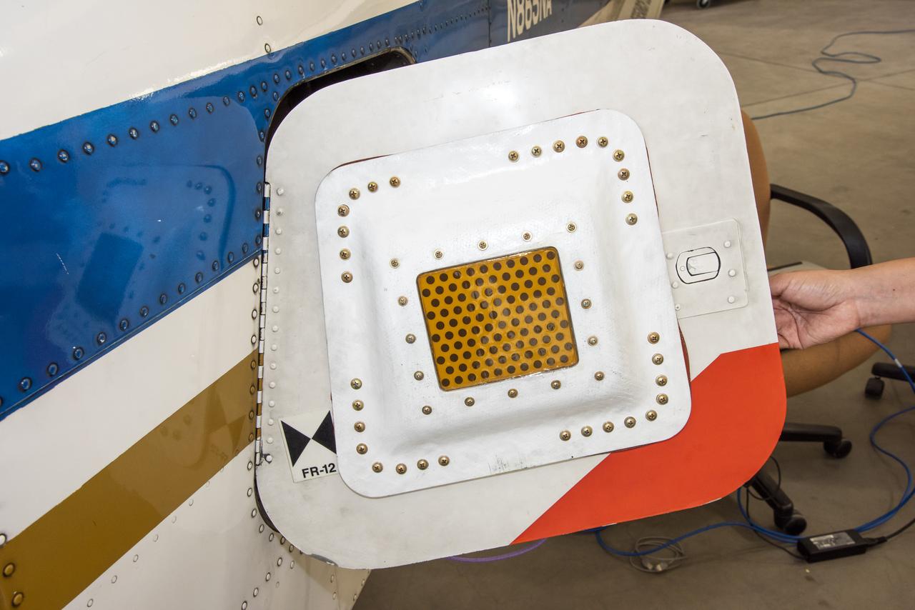
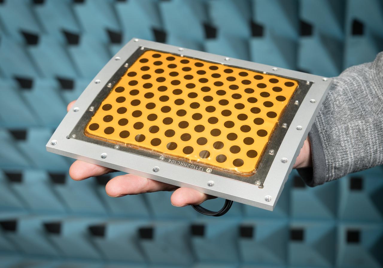
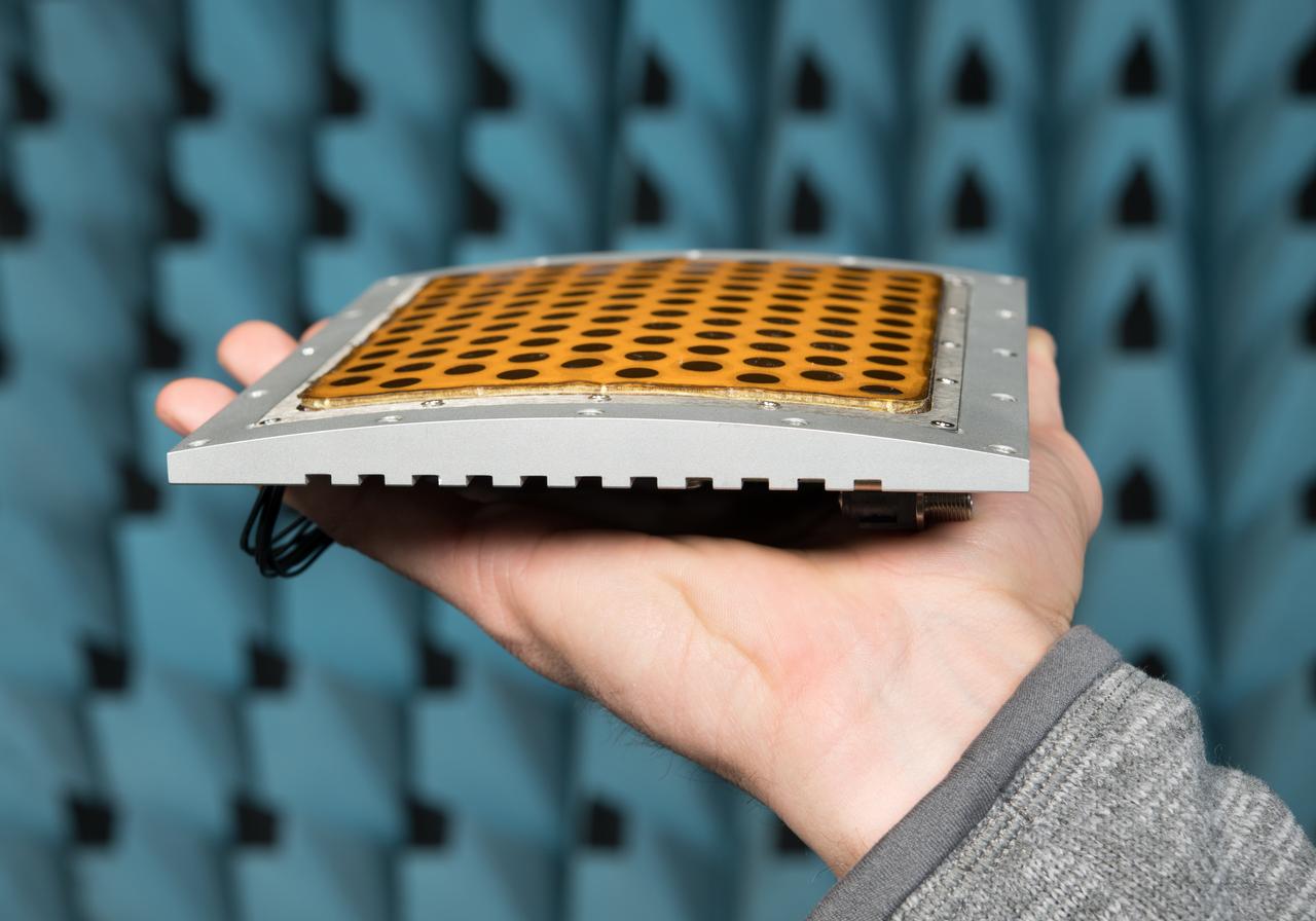
A photo of the conformal antenna installed on the door of T-34C aircraft. The conformal antenna was developed and designed by members of the Conformal Lightweight Antenna Structures for Aeronautical Communications Technologies activity within the Convergent Aeronautics Solutions project. The antenna is made of aerogels which have resulted in a thin, flexible antenna substrate with improved gain, bandwidth and efficiency.
Flight Electronics Payload for Curved Confocal Lightweight Antenna Structures for Aeronautical Communications Technologies, CLAS-ACT, Phased Array Antenna on T-34-C Aircraft Door Flight Curved Confocal Lightweight Antenna Structures for Aeronautical Communications Technologies, CLAS-ACT, Phased Array Antenna Control / Flight Testing

NASA's Armstrong Flight Research Center installed a conformal antenna on the door of its T-34C aircraft to test its performance parameters. The conformal antenna was designed through a cross-center collaboration through the Conformal Lightweight Antenna Structures for Aeronautical Communications Technologies project.
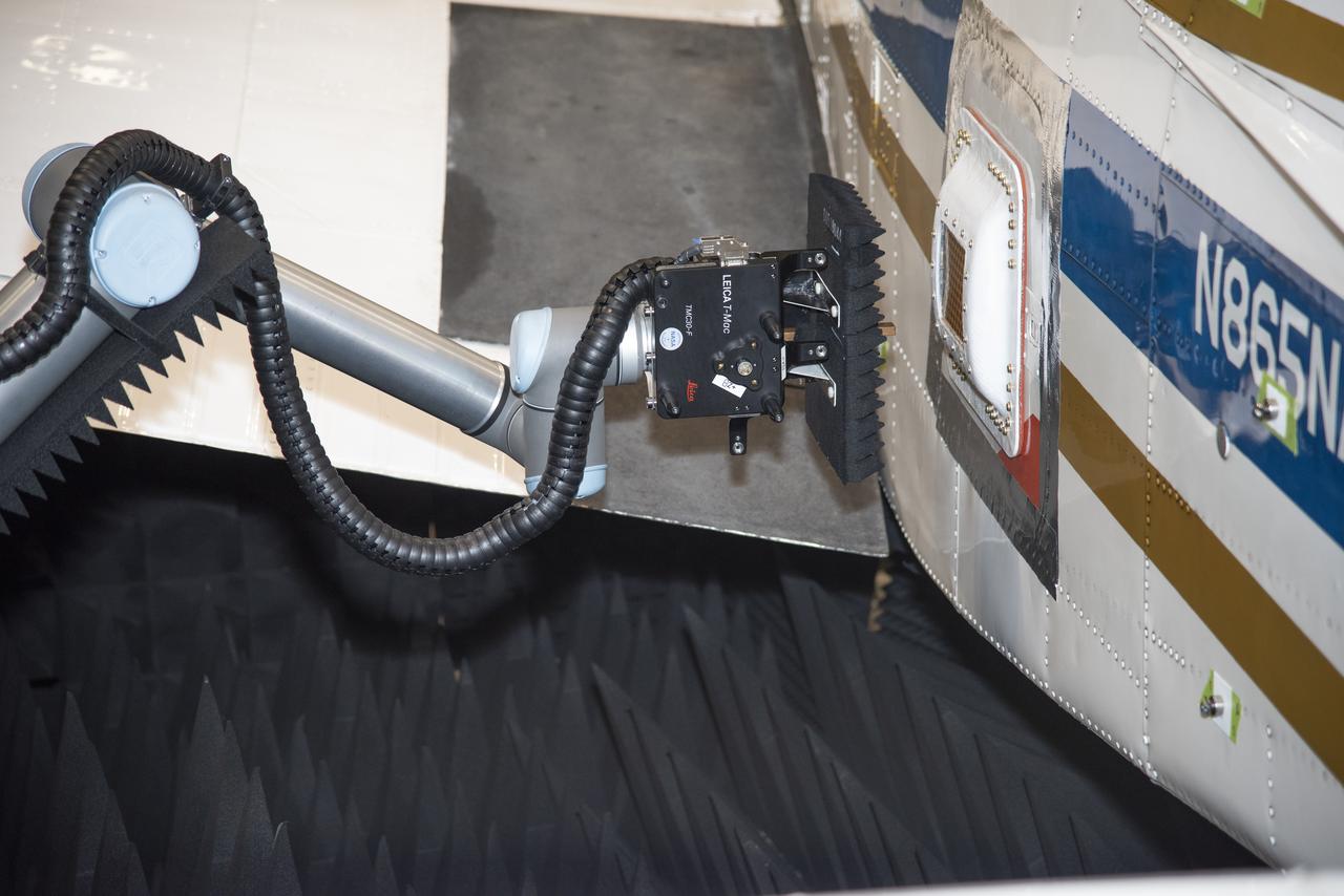
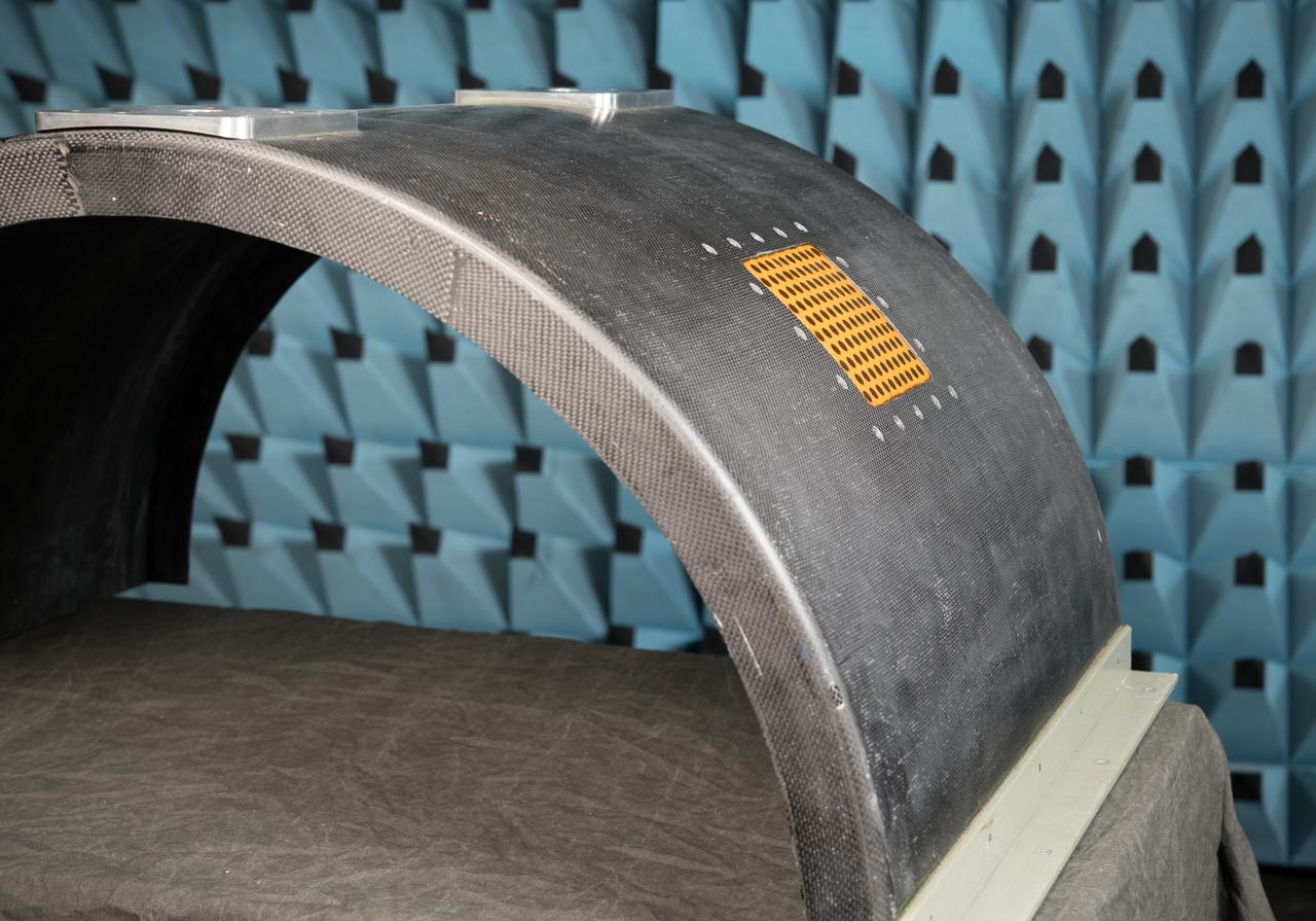
Tests were conducted with a robotic antenna scanner at NASA's Armstrong Flight Research Center in California. The scanner was used to test the in-situ radiation pattern of the conformal antenna to verify its performance parameters before being tested on an aircraft.
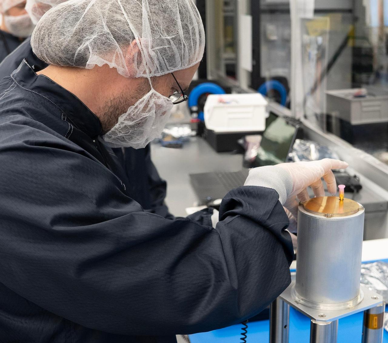
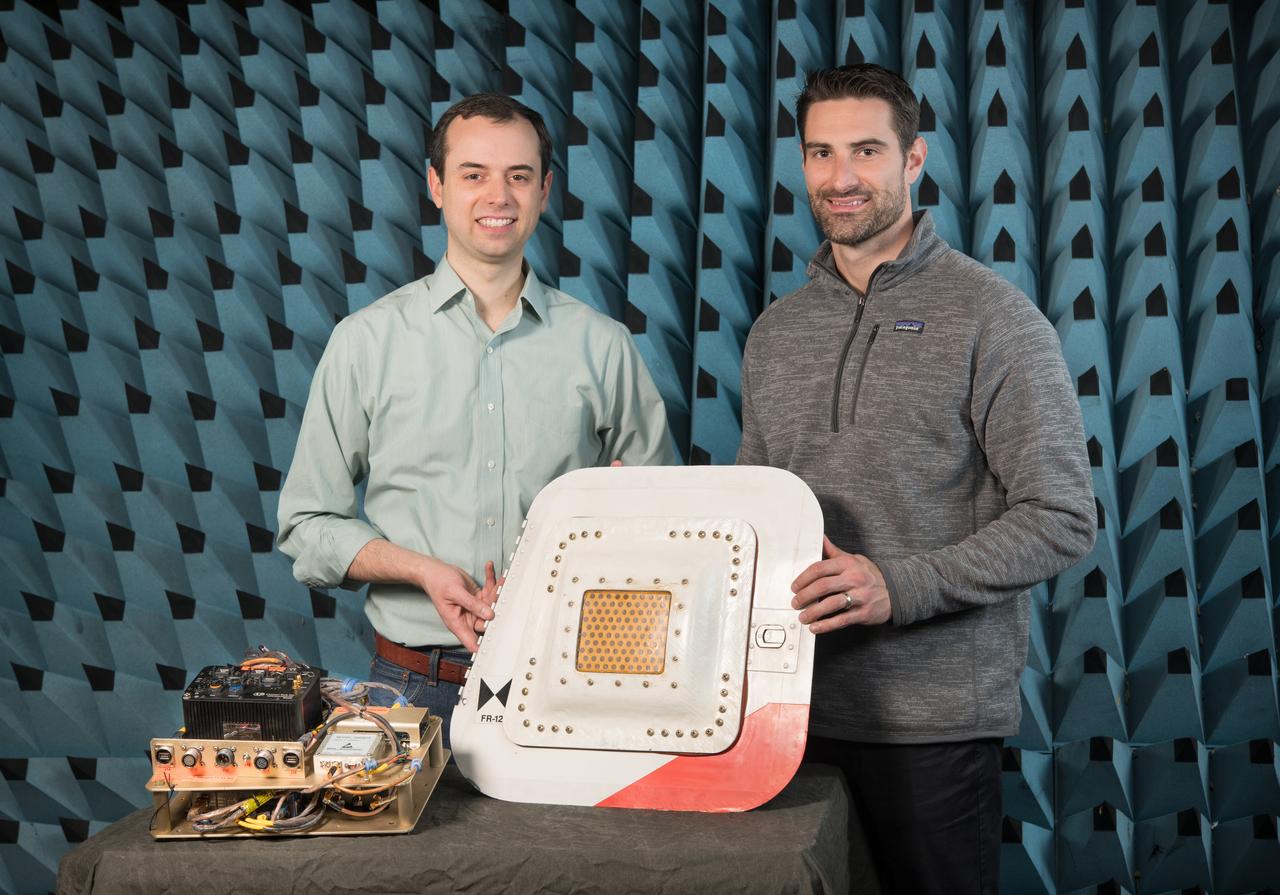
Engineer Emmanuel Decrossas of NASA's Jet Propulsion Laboratory in Southern California makes an adjustment to an antenna's connector, part of a NASA telecommunications payload called User Terminal, at Firefly Aerospace's facility in Cedar Park, Texas, in August 2025. Figure A (https://photojournal.jpl.nasa.gov/figures/PIA26596_figA.jpg) shows members of the team from JPL and NASA (dark blue) and Firefly (white) with the User Terminal antenna, radio, and other components on the bench behind them. Managed by JPL, the User Terminal will test a new, low-cost lunar communications system that future missions to the Moon's far side could use to transfer data to and from Earth via lunar relay satellite. The User Terminal payload will be installed atop Firefly's Blue Ghost Mission 2 lunar lander, which is slated to launch to the Moon's far side in 2026 under NASA's CLPS (Commercial Lunar Payload Services) initiative. NASA's Apollo missions brought large and powerful telecommunications systems to the lunar near-side surface to communicate directly with Earth. But spacecraft on the far side will not have that option because only the near side of the Moon is visible to Earth. Sending messages between the Moon and Earth via a relay orbiter enables communication with the lunar far side and improves it at the Moon's poles. The User Terminal will for the first time test such a setup for NASA by using a compact, lightweight software defined radio, antenna, and related hardware to communicate with a satellite that Blue Ghost Mission 2 is delivering to lunar orbit: ESA's (the European Space Agency's) Lunar Pathfinder. The User Terminal radio and antenna installed on the Blue Ghost lander will be used to commission Lunar Pathfinder, sending test data back and forth. After the lander ceases operations as planned at the end of a single lunar day (about 14 Earth days), a separate User Terminal radio and antenna installed on LuSEE-Night – another payload on the lander – will send LuSEE-Night's data to Lunar Pathfinder, which will relay the information to a commercial network of ground stations on Earth. LuSEE-Night is a radio telescope that expected to operate for at least 1½ years; it is a joint effort by NASA, the U.S. Department of Energy, and University of California, Berkeley's Space Sciences Laboratory. Additionally, User Terminal will be able to communicate with another satellite that's being delivered to lunar orbit by Blue Ghost Mission 2: Firefly's own Elytra Dark orbital vehicle. The hardware on the lander is only part of the User Terminal project, which was also designed to implement a new S-band two-way protocol, or standard, for short-range space communications between entities on the lunar surface (such as rovers and landers) and lunar orbiters, enabling reliable data transfer between them. The standard is a new version of a space communications protocol called Proximity-1 that was initially developed more than two decades ago for use at Mars by an international standard body called the Consultative Committee for Space Data Systems (CCSDS), of which NASA is a member agency. The User Terminal team made recommendations to CCSDS on the development of the new lunar S-band standard, which was specified in 2024. The new standard will enable lunar orbiters and surface spacecraft from various entities – NASA and other civil space agencies as well as industry and academia – to communicate with each other, a concept known as interoperability. At Mars, NASA rovers communicate with various Red Planet orbiters using the Ultra-High Frequency (UHF) radio band version of the Proximity-1 standard. On the Moon's far side, use of UHF is reserved for radio astronomy science; so a new lunar standard was needed using a different frequency range, S-band, as were more efficient modulation and coding schemes to better fit the available frequency spectrum specified by the new standard. User Terminal is funded by NASA's Exploration Science Strategy and Integration Office, part of the agency's Science Mission Directorate, which manages the CLPS initiative. JPL manages the project and supported development of the new S-band radio standard and the payload in coordination with Vulcan Wireless in Carlsbad, California, which built the radio. Caltech in Pasadena manages JPL for NASA. https://photojournal.jpl.nasa.gov/catalog/PIA26596
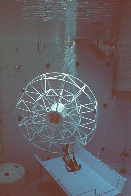
Once the United States' space program had progressed from Earth's orbit into outerspace, the prospect of building and maintaining a permanent presence in space was realized. To accomplish this feat, NASA launched a temporary workstation, Skylab, to discover the effects of low gravity and weightlessness on the human body, and also to develop tools and equipment that would be needed in the future to build and maintain a more permanent space station. The structures, techniques, and work schedules had to be carefully designed to fit this unique construction site. The components had to be lightweight for transport into orbit, yet durable. The station also had to be made with removable parts for easy servicing and repairs by astronauts. All of the tools necessary for service and repairs had to be designed for easy manipulation by a suited astronaut. And construction methods had to be efficient due to limited time the astronauts could remain outside their controlled environment. In lieu of all the specific needs for this project, an environment on Earth had to be developed that could simulate a low gravity atmosphere. A Neutral Buoyancy Simulator (NBS) was constructed by NASA Marshall Space Flight Center (MSFC) in 1968. Since then, NASA scientists have used this facility to understand how humans work best in low gravity and also provide information about the different kinds of structures that can be built. Included in the plans for the space station was a space telescope. This telescope would be attached to the space station and directed towards outerspace. Astronomers hoped that the space telescope would provide a look at space that is impossible to see from Earth because of Earth's atmosphere and other man made influences. Pictured is a large structure that is being used as the antenna base for the space telescope.