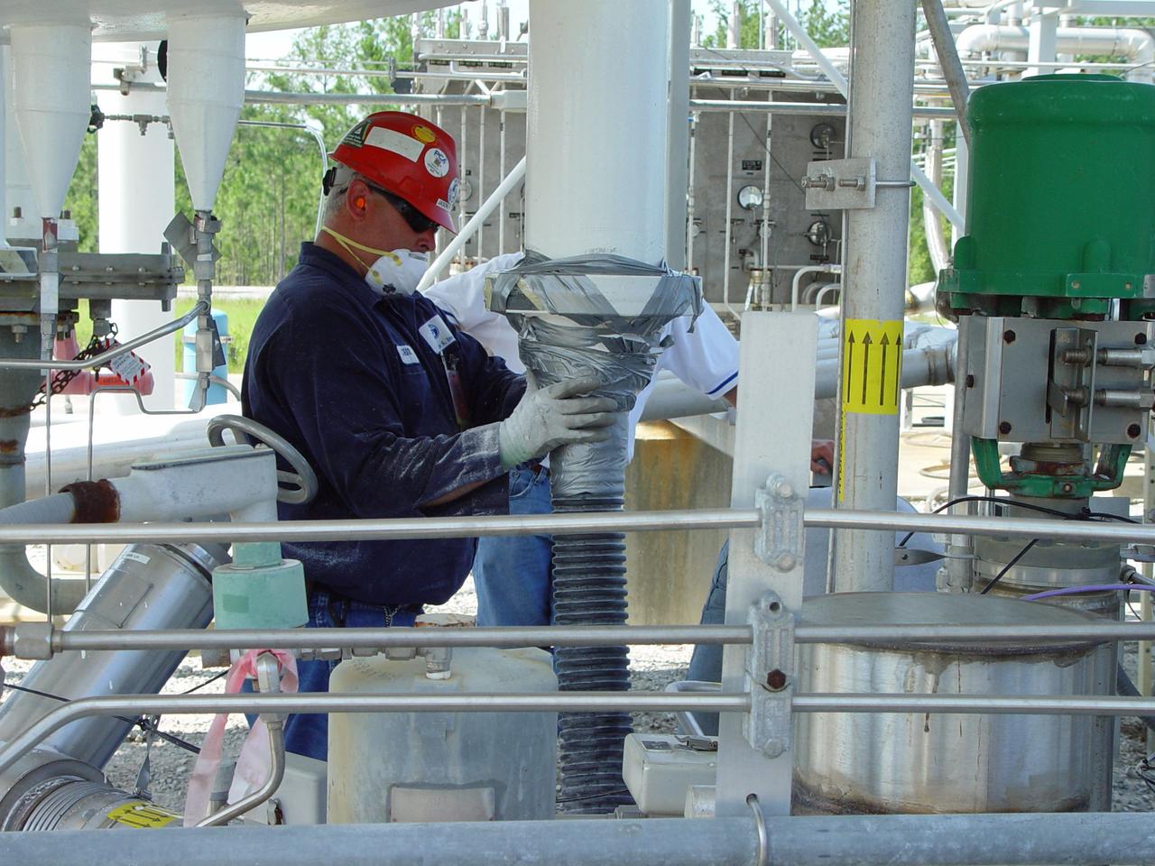
A worker removes Perlite insulation from a liquid hydrogen storage tank to replace it with glass bubble insulation.
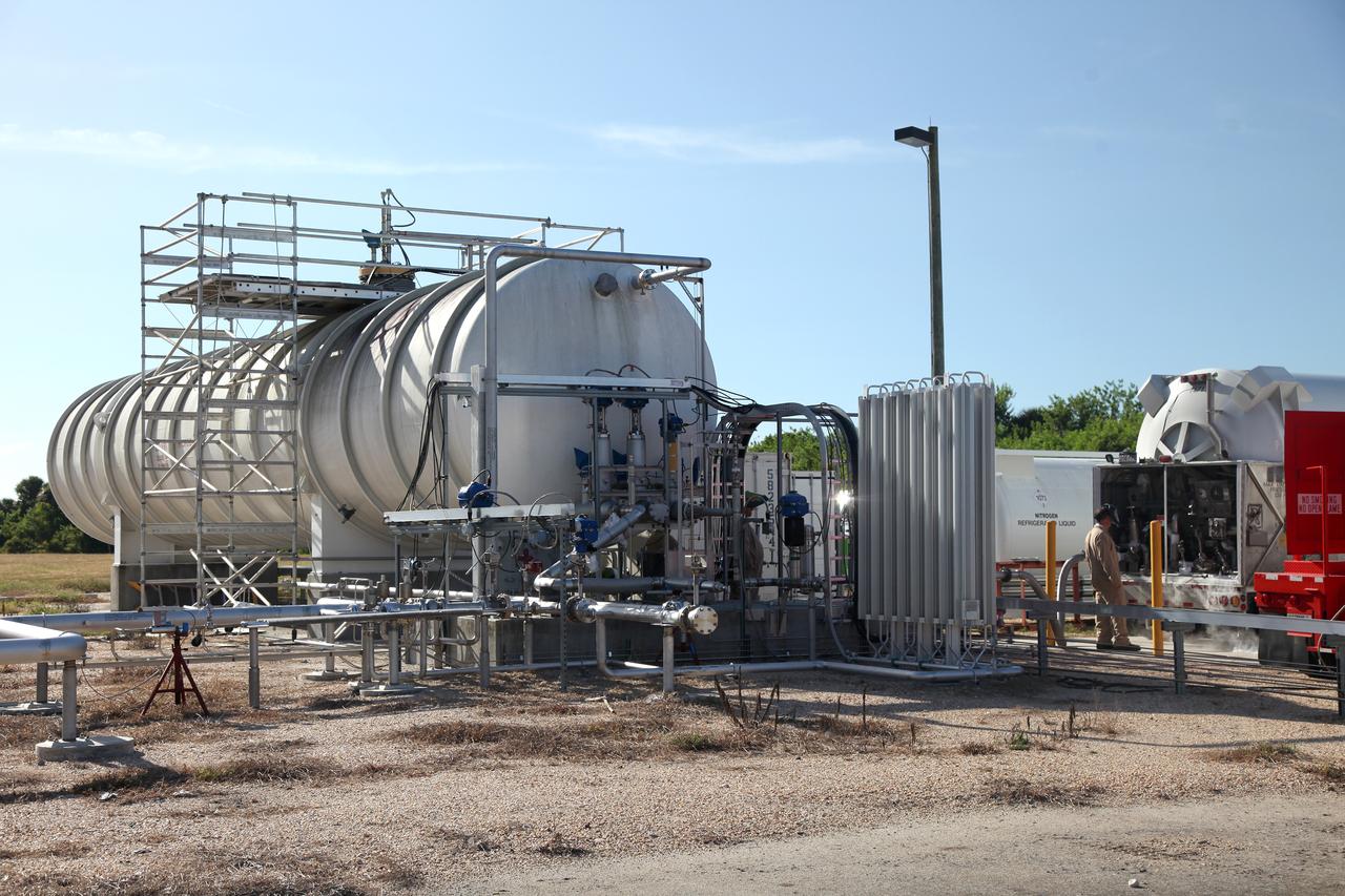
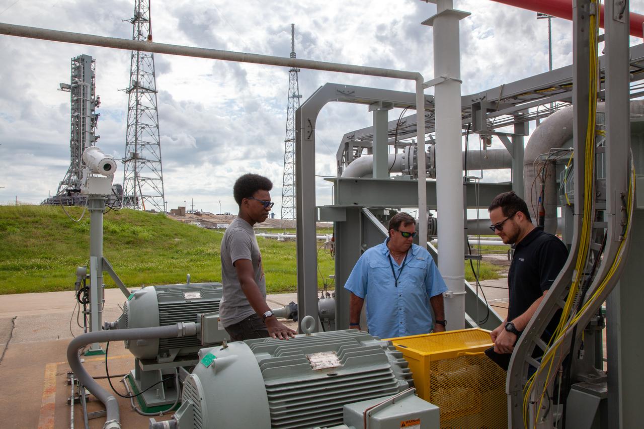
Engineers complete a test of the Ground Operations Demo Unit for liquid hydrogen at NASA's Kennedy Space Center in Florida. The system includes a 33,000 gallon liquid hydrogen storage tank with an internal cold heat exchanger supplied from a cryogenic refrigerator. The primary goal of the testing is to achieve a liquid hydrogen zero boil-off capability. The system was designed, installed and tested by a team of civil servants and contractors from the center's Cryogenic Test Laboratory, with support from engineers at NASA's Glenn Research Center in Cleveland and Stennis Space Center in Mississippi. It may be applicable for use by the Ground Systems Development and Operations Program at Launch Pad 39B.
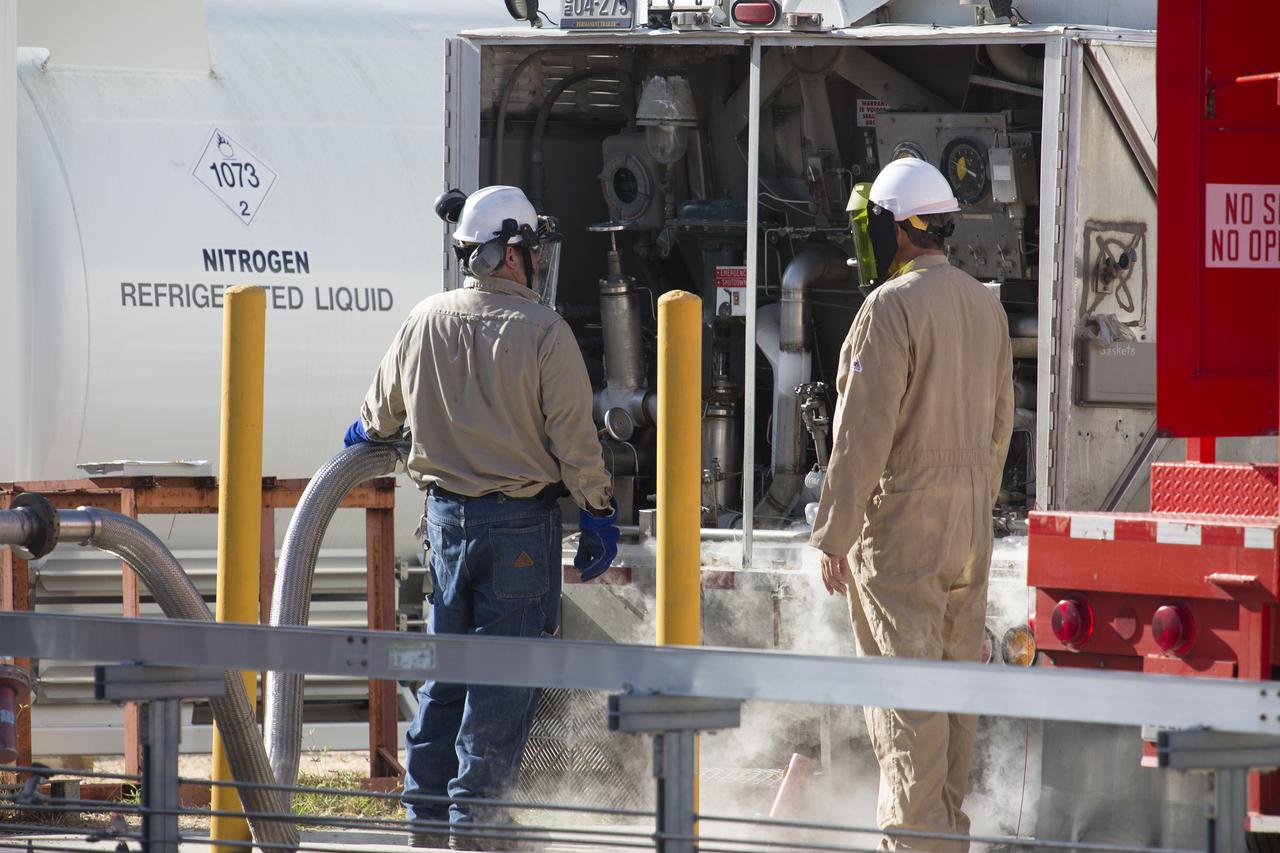
Technicians with Praxair pressurize the hydrogen trailer before offloading liquid hydrogen during a test of the Ground Operations Demo Unit for liquid hydrogen at NASA's Kennedy Space Center in Florida. The system includes a 33,000 gallon liquid hydrogen storage tank with an internal cold heat exchanger supplied from a cryogenic refrigerator. The primary goal of the testing is to achieve a liquid hydrogen zero boil-off capability. The system was designed, installed and tested by a team of civil servants and contractors from the center's Cryogenic Test Laboratory, with support from engineers at NASA's Glenn Research Center in Cleveland and Stennis Space Center in Mississippi. It may be applicable for use by the Ground Systems Development and Operations Program at Launch Pad 39B.
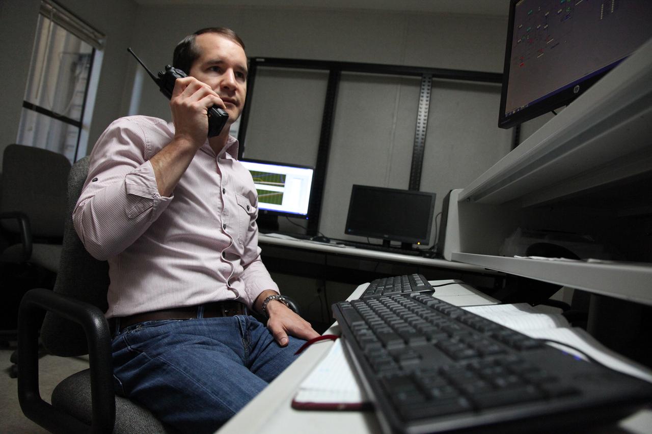
Inside a control building at NASA's Kennedy Space Center in Florida, Adam Swinger, cryogenic research engineer in the Exploration Research and Technology Directorate, communicates with team members during a test of the Ground Operations Demo Unit for liquid hydrogen. The system includes a 33,000 gallon liquid hydrogen storage tank with an internal cold heat exchanger supplied from a cryogenic refrigerator. The primary goal of the testing is to achieve a liquid hydrogen zero boil-off capability. The system was designed, installed and tested by a team of civil servants and contractors from the center's Cryogenic Test Laboratory, with support from engineers at NASA's Glenn Research Center in Cleveland and Stennis Space Center in Mississippi. It may be applicable for use by the Ground Systems Development and Operations Program at Launch Pad 39B.
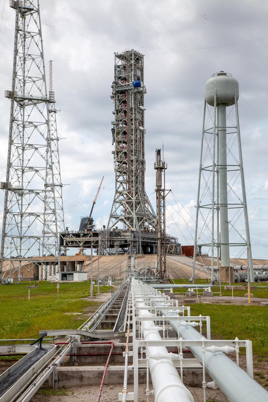
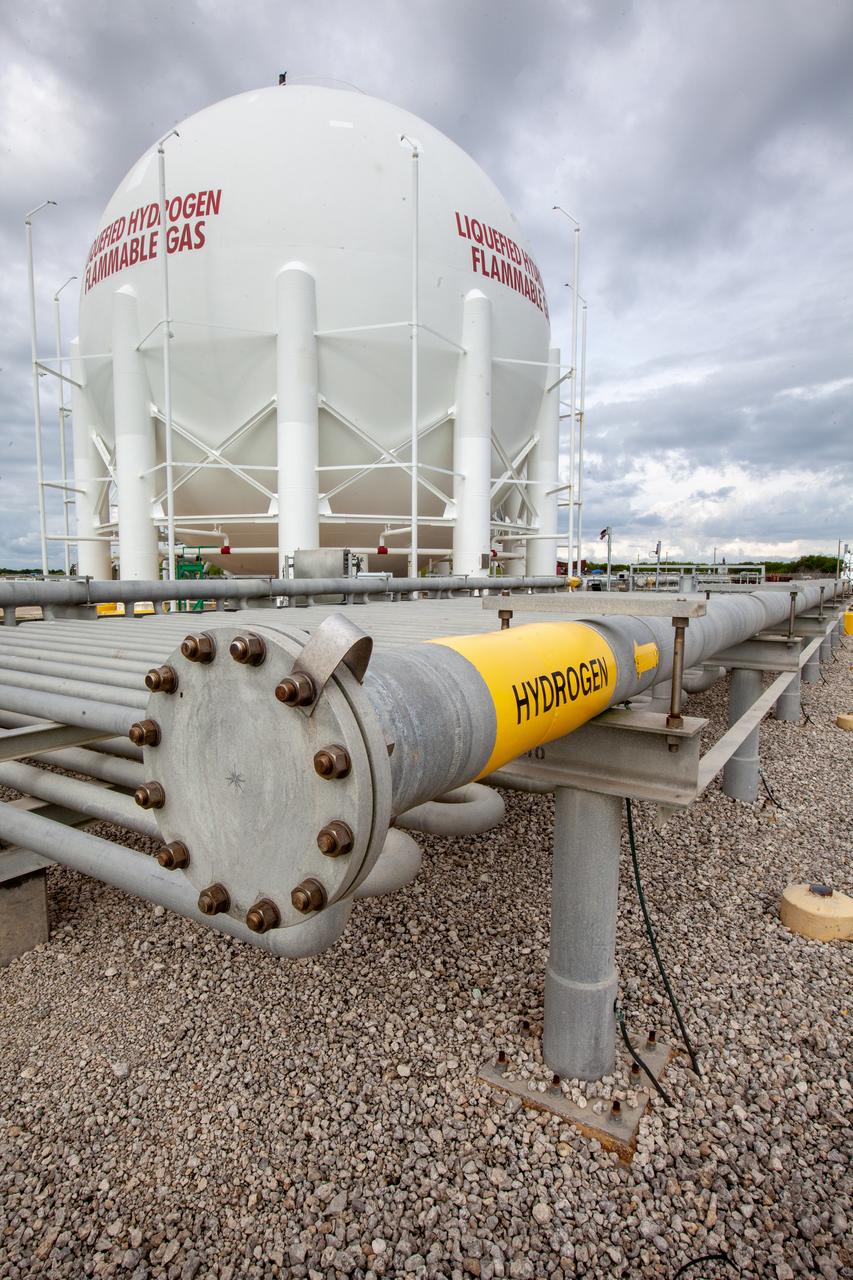
In this view, the cross country line that liquid hydrogen will flow through can be seen stretching from the storage tank to the mobile launcher (ML) at Launch Pad 39B on Nov. 8, 2019, at NASA’s Kennedy Space Center in Florida. The agency’s Exploration Ground Systems oversaw testing of the pad’s cryogenic systems – the infrastructure that will send liquid hydrogen and liquid oxygen from the storage tanks to the Space Launch System (SLS) rocket – in preparation for the launch of SLS with the Orion spacecraft atop for the uncrewed Artemis I mission. Each of the liquid hydrogen and liquid oxygen tanks can hold more than 800,000 gallons of propellant. The liquid hydrogen, lighter than liquid oxygen, will make its way from the tank to the rocket using gaseous hydrogen to pressurize the sphere at the time of launch, while the liquid oxygen will be sent to the rocket via pumps.
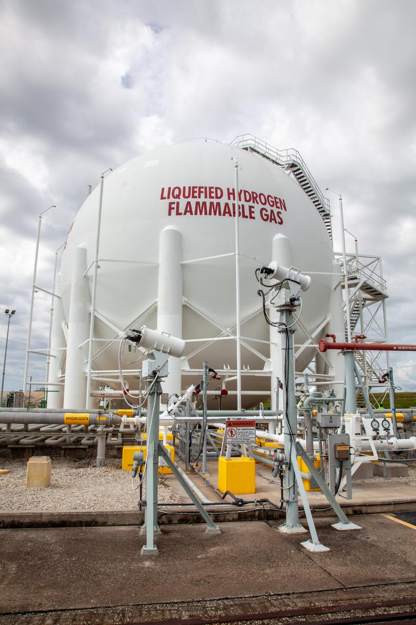
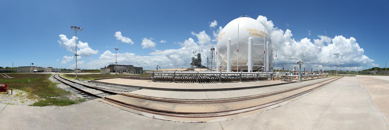
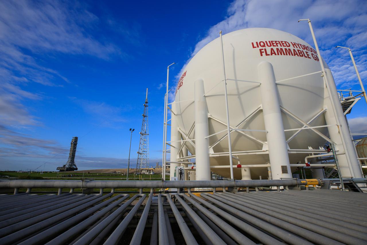
A liquid hydrogen storage tank is photographed at Launch Pad 39B on Nov. 8, 2019, at NASA’s Kennedy Space Center in Florida. The agency’s Exploration Ground Systems oversaw testing of the pad’s cryogenic systems – the infrastructure that will support the flow of liquid hydrogen and liquid oxygen from the storage tanks to the Space Launch System (SLS) rocket – in preparation for the launch of SLS with the Orion spacecraft atop for the uncrewed Artemis I mission. Each of the liquid hydrogen and liquid oxygen tanks can hold more than 800,000 gallons of propellant. The liquid hydrogen, lighter than liquid oxygen, will make its way from the tank to the rocket using gaseous hydrogen to pressurize the sphere at the time of launch, while the liquid oxygen will be sent to the rocket via pumps.
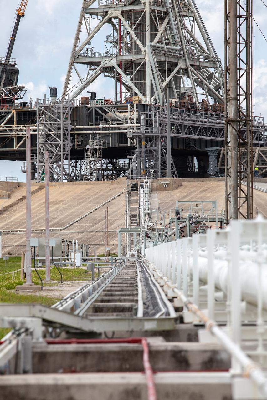
In this view, the cross country line that liquid hydrogen will flow through can be seen stretching from the storage tank to the mobile launcher (ML) at Launch Pad 39B on Nov. 8, 2019, at NASA’s Kennedy Space Center in Florida. The agency’s Exploration Ground Systems oversaw testing of the pad’s cryogenic systems – the infrastructure that will send liquid hydrogen and liquid oxygen from the storage tanks to the Space Launch System (SLS) rocket – in preparation for the launch of SLS with the Orion spacecraft atop for the uncrewed Artemis I mission. Each of the liquid hydrogen and liquid oxygen tanks can hold more than 800,000 gallons of propellant. The liquid hydrogen, lighter than liquid oxygen, will make its way from the tank to the rocket using gaseous hydrogen to pressurize the sphere at the time of launch, while the liquid oxygen will be sent to the rocket via pumps.
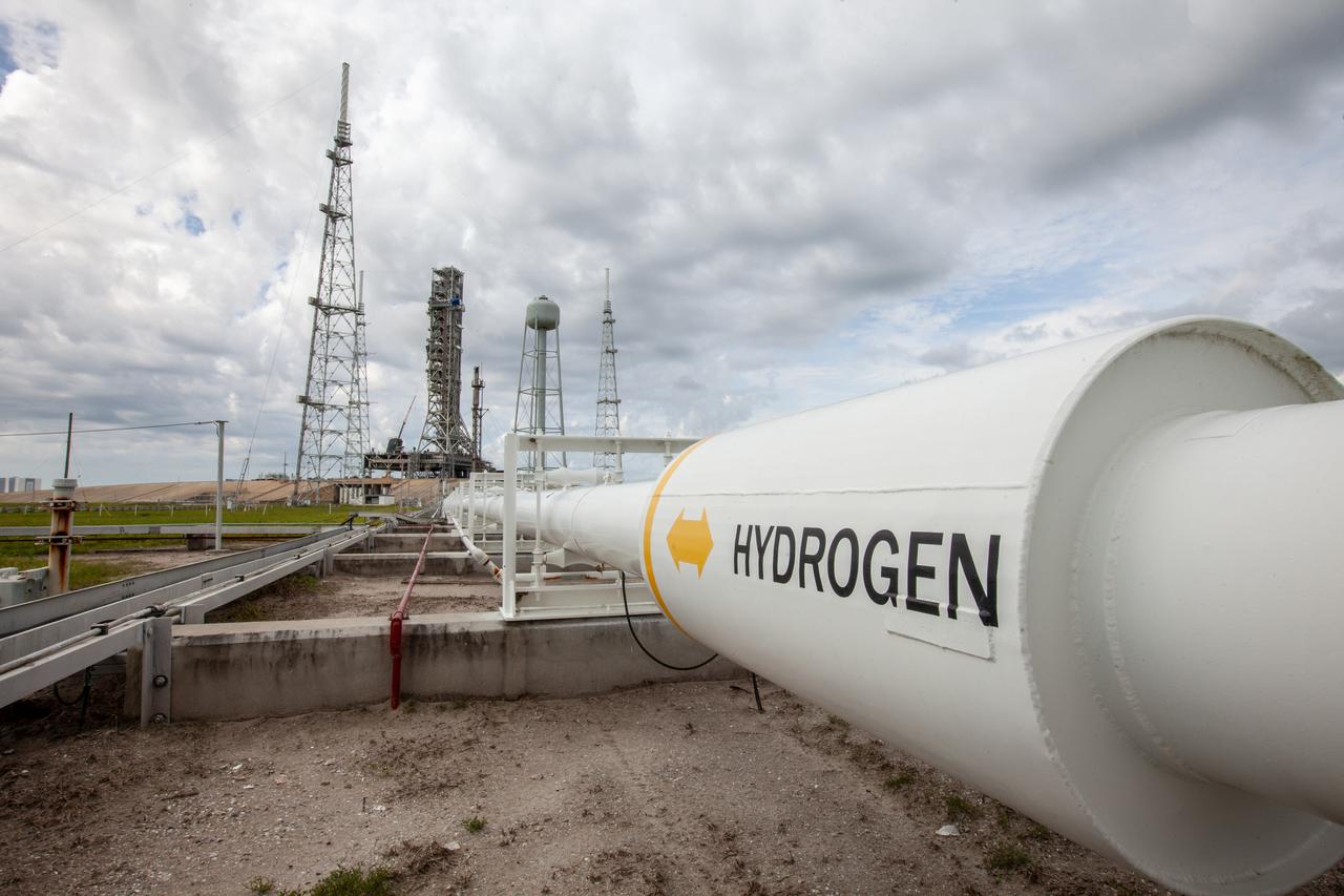
The cross country line that liquid hydrogen will flow through from the storage tank to the mobile launcher for the launch of NASA’s uncrewed Artemis I mission is photographed at Launch pad 39B on Nov. 8, 2019, at the agency’s Kennedy Space Center in Florida. NASA’s Exploration Ground Systems oversaw testing of the pad’s cryogenic systems – the infrastructure that will send the liquid hydrogen and liquid oxygen from the storage tanks to the Space Launch System (SLS) rocket – in preparation for the launch of SLS with the Orion spacecraft atop. Each of the liquid hydrogen and liquid oxygen tanks can hold more than 800,000 gallons of propellant. The liquid hydrogen, lighter than liquid oxygen, will make its way from the tank to the rocket using gaseous hydrogen to pressurize the sphere at the time of launch, while the liquid oxygen will be sent to the rocket via pumps.
A liquid hydrogen storage tank is photographed at Launch Pad 39B on Nov. 8, 2019, at NASA’s Kennedy Space Center in Florida. The agency’s Exploration Ground Systems oversaw testing of the pad’s cryogenic systems – the infrastructure that will support the flow of liquid hydrogen and liquid oxygen from the storage tanks to the Space Launch System (SLS) rocket – in preparation for the launch of SLS with the Orion spacecraft atop for the uncrewed Artemis I mission. Each of the liquid hydrogen and liquid oxygen tanks can hold more than 800,000 gallons of propellant. The liquid hydrogen, lighter than liquid oxygen, will make its way from the tank to the rocket using gaseous hydrogen to pressurize the sphere at the time of launch, while the liquid oxygen will be sent to the rocket via pumps.
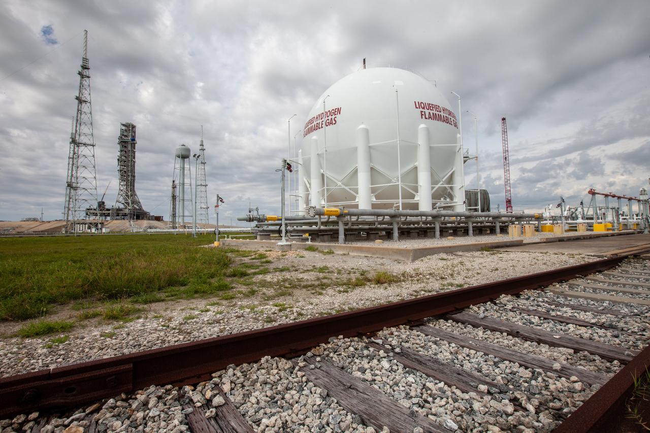
A liquid hydrogen storage tank, with a view of the mobile launcher on the pad surface in the background, is photographed at Launch Pad 39B on Nov. 8, 2019, at NASA’s Kennedy Space Center in Florida. The agency’s Exploration Ground Systems oversaw testing of the pad’s cryogenic systems – the infrastructure that will support the flow of liquid hydrogen and liquid oxygen from the storage tanks to the Space Launch System (SLS) rocket – in preparation for the launch of SLS with the Orion spacecraft atop for the uncrewed Artemis I mission. Each of the liquid hydrogen and liquid oxygen tanks can hold more than 800,000 gallons of propellant. The liquid hydrogen, lighter than liquid oxygen, will make its way from the tank to the rocket using gaseous hydrogen to pressurize the sphere at the time of launch, while the liquid oxygen will be sent to the rocket via pumps.
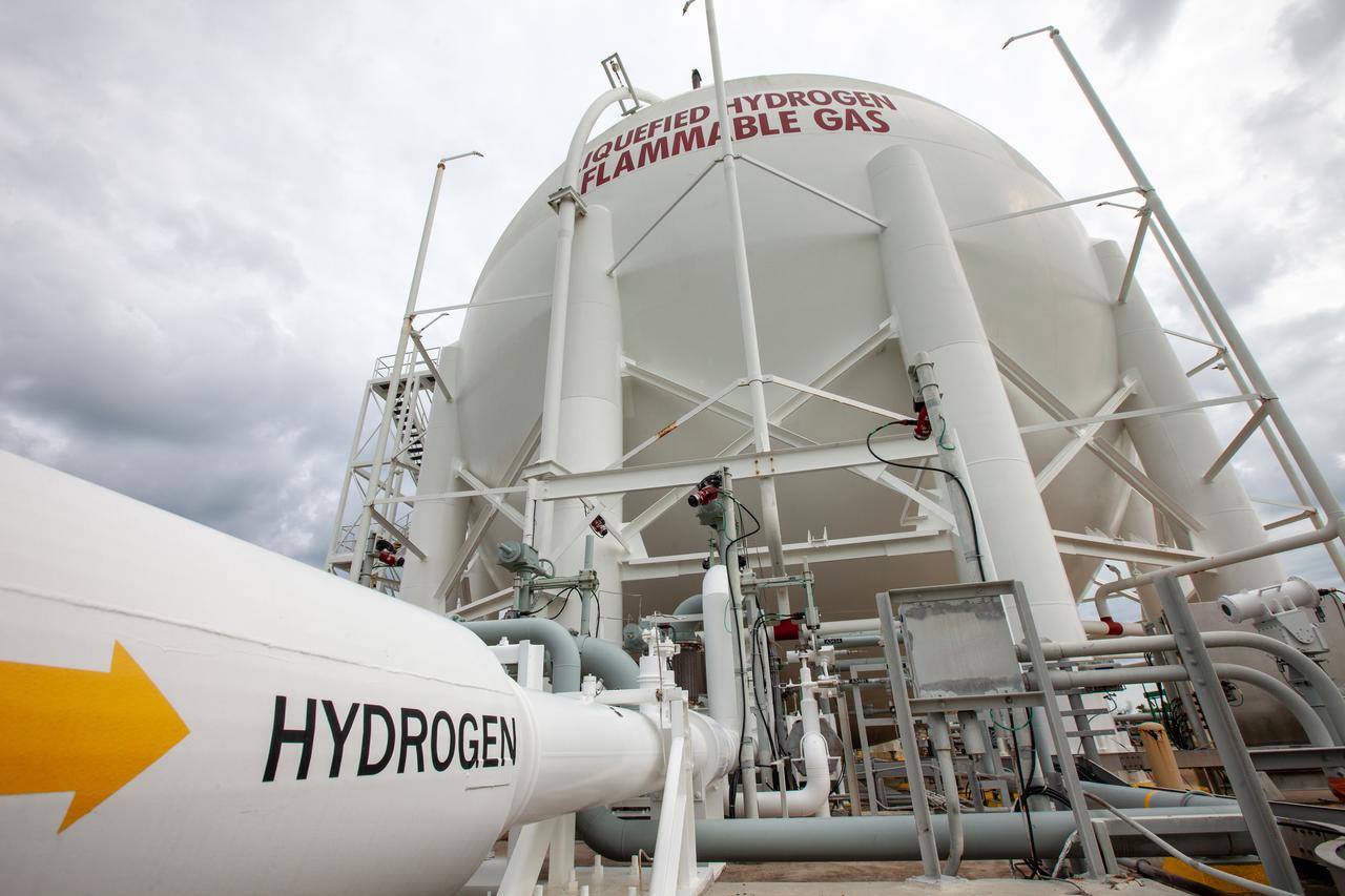
A liquid hydrogen storage tank is photographed at Launch Pad 39B on Nov. 8, 2019, at NASA’s Kennedy Space Center in Florida. The agency’s Exploration Ground Systems oversaw testing of the pad’s cryogenic systems – the infrastructure that will support the flow of liquid hydrogen and liquid oxygen from the storage tanks to the Space Launch System (SLS) rocket – in preparation for the launch of SLS with the Orion spacecraft atop for the uncrewed Artemis I mission. Each of the liquid hydrogen and liquid oxygen tanks can hold more than 800,000 gallons of propellant. The liquid hydrogen, lighter than liquid oxygen, will make its way from the tank to the rocket using gaseous hydrogen to pressurize the sphere at the time of launch, while the liquid oxygen will be sent to the rocket via pumps.
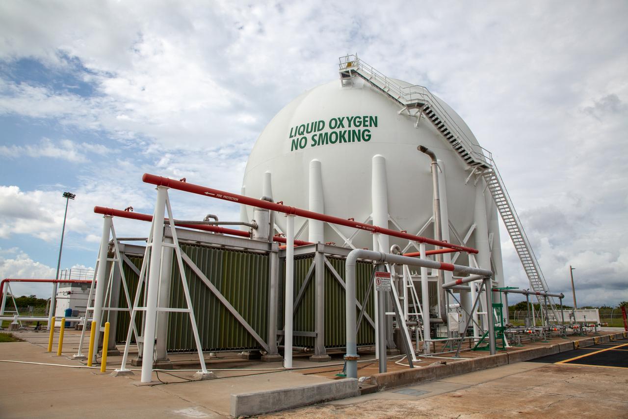
From left, liquid oxygen engineers Josh Jones, Jim Loup and Rene DeLaCruz on Kennedy Space Center’s Test Operations and Support Contract inspect equipment surrounding the liquid oxygen storage tank at Launch Pad 39B on Nov. 8, 2019. The agency’s Exploration Ground Systems oversaw testing of the pad’s cryogenic systems – the infrastructure that will support the flow of liquid hydrogen and liquid oxygen from the storage tanks to the Space Launch System (SLS) rocket – in preparation for the launch of SLS with the Orion spacecraft atop for the uncrewed Artemis I mission. Each of the liquid oxygen and liquid hydrogen tanks can hold more than 800,000 gallons of propellant. The liquid oxygen will require the use of pumps to push it from the tank to the rocket, while the lighter liquid hydrogen will make its way up to the pad using gaseous hydrogen to pressurize the sphere.
In this view from the pad surface at Kennedy Space Center’s Launch Pad 39B, the cross country line that liquid oxygen will flow through can be seen stretching from the pad to the liquid oxygen storage tank on Nov. 8, 2019. The agency’s Exploration Ground Systems oversaw testing of the pad’s cryogenic systems – the infrastructure that will support the flow of liquid hydrogen and liquid oxygen from the storage tanks to the Space Launch System (SLS) rocket – in preparation for the launch of SLS with the Orion spacecraft atop for the uncrewed Artemis I mission. Each of the liquid oxygen and liquid hydrogen tanks can hold more than 800,000 gallons of propellant. The liquid oxygen will require the use of pumps to push it from the tank to the rocket, while the lighter liquid hydrogen will make its way up to the pad using gaseous hydrogen to pressurize the sphere.
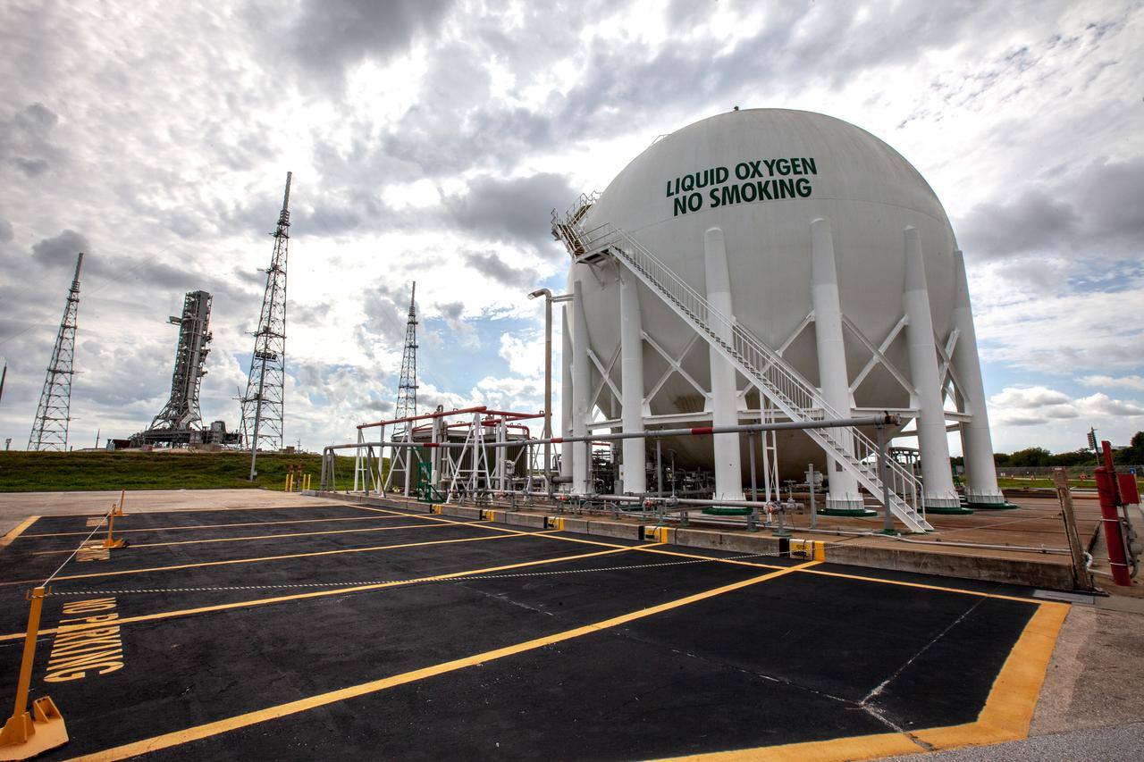
A liquid oxygen storage tank, with a view of the mobile launcher on the pad surface in the background, is photographed at Launch Pad 39B on Nov. 8, 2019, at NASA’s Kennedy Space Center in Florida. The agency’s Exploration Ground Systems oversaw testing of the pad’s cryogenic systems – the infrastructure that will support the flow of liquid hydrogen and liquid oxygen from the storage tanks to the Space Launch System (SLS) rocket – in preparation for the launch of SLS with the Orion spacecraft atop for the uncrewed Artemis I mission. Each of the liquid oxygen and liquid hydrogen tanks can hold more than 800,000 gallons of propellant. The liquid oxygen will require the use of pumps to push it from the tank to the rocket, while the lighter liquid hydrogen will make its way up to the pad using gaseous hydrogen to pressurize the sphere.

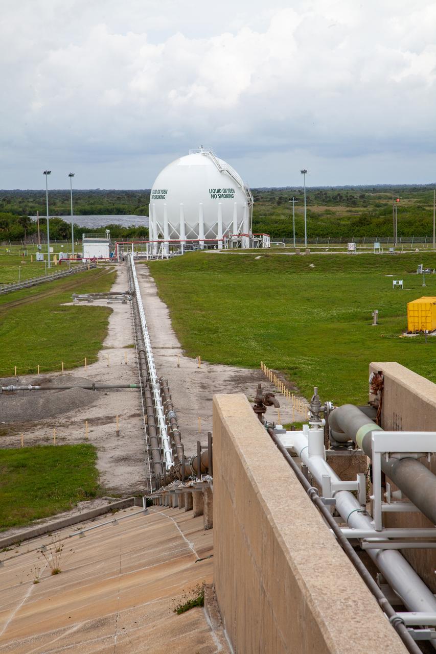
In this view, the cross country line that liquid oxygen will flow through can be seen stretching from the storage tank to the mobile launcher at Launch Pad 39B on Nov. 8, 2019, at NASA’s Kennedy Space Center in Florida. The agency’s Exploration Ground Systems oversaw testing of the pad’s cryogenic systems – the infrastructure that will send liquid hydrogen and liquid oxygen from the storage tanks to the Space Launch System (SLS) rocket – in preparation for the launch of SLS with the Orion spacecraft atop for the uncrewed Artemis I mission. Each of the liquid oxygen and liquid hydrogen tanks can hold more than 800,000 gallons of propellant. The liquid oxygen will require the use of pumps to push it from the tank to the rocket, while the lighter liquid hydrogen will make its way up to the pad using gaseous hydrogen to pressurize the sphere.
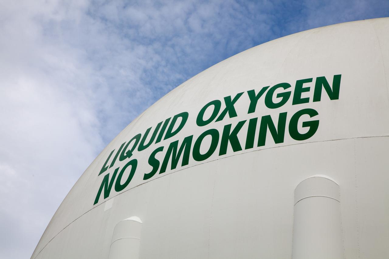
A liquid oxygen storage tank is photographed at Launch Pad 39B on Nov. 8, 2019, at NASA’s Kennedy Space Center in Florida. The agency’s Exploration Ground Systems oversaw testing of the pad’s cryogenic systems – the infrastructure that will support the flow of liquid hydrogen and liquid oxygen from the storage tanks to the Space Launch System (SLS) rocket – in preparation for the launch of SLS with the Orion spacecraft atop for the uncrewed Artemis I mission. Each of the liquid oxygen and liquid hydrogen tanks can hold more than 800,000 gallons of propellant. The liquid oxygen will require the use of pumps to push it from the tank to the rocket, while the lighter liquid hydrogen will make its way up to the pad using gaseous hydrogen to pressurize the sphere.
A liquid oxygen storage tank is photographed at Launch Pad 39B on Nov. 8, 2019, at NASA’s Kennedy Space Center in Florida. The agency’s Exploration Ground Systems oversaw testing of the pad’s cryogenic systems – the infrastructure that will support the flow of liquid hydrogen and liquid oxygen from the storage tanks to the Space Launch System (SLS) rocket – in preparation for the launch of SLS with the Orion spacecraft atop for the uncrewed Artemis I mission. Each of the liquid oxygen and liquid hydrogen tanks can hold more than 800,000 gallons of propellant. The liquid oxygen will require the use of pumps to push it from the tank to the rocket, while the lighter liquid hydrogen will make its way up to the pad using gaseous hydrogen to pressurize the sphere.
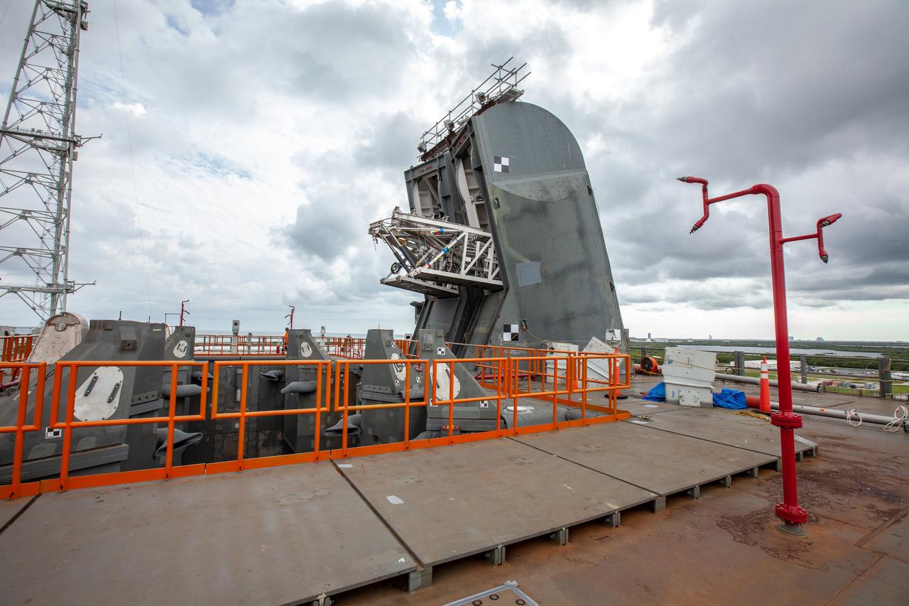
The Tail Service Mast Umbilicals that will connect to NASA’s Space Launch System (SLS) rocket, containing fluid lines for liquid oxygen and liquid hydrogen propellant loading, are photographed on the mobile launcher at Launch Pad 39B on Nov. 8, 2019, at the agency’s Kennedy Space Center in Florida. NASA’s Exploration Ground Systems oversaw testing of the pad’s cryogenic systems – the infrastructure that will support the flow of liquid hydrogen and liquid oxygen from the storage tanks to the rocket – in preparation for the launch of SLS with the Orion spacecraft atop for the uncrewed Artemis I mission. Each of the liquid oxygen and liquid hydrogen tanks can hold more than 800,000 gallons of propellant. The liquid oxygen will require the use of pumps to push it from the tank to the rocket, while the lighter liquid hydrogen will make its way up to the pad using gaseous hydrogen to pressurize the sphere.
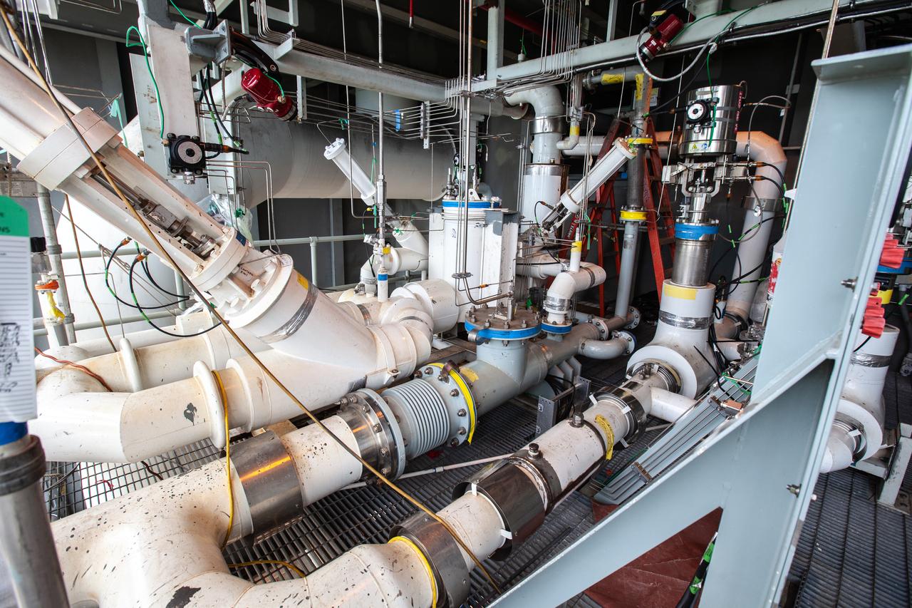
The control panel that will direct and control the flow of liquid oxygen and liquid oxygen, referred to as a skid, is photographed at Launch Pad 39B on Nov. 8, 2019, at NASA’s Kennedy Space Center in Florida. The agency’s Exploration Ground Systems oversaw testing of the pad’s cryogenic systems – the infrastructure that will send the liquid hydrogen and liquid oxygen from the storage tanks to the Space Launch System (SLS) rocket – in preparation for the launch of SLS with the Orion spacecraft atop for the uncrewed Artemis I mission. Each of the liquid oxygen and liquid hydrogen tanks can hold more than 800,000 gallons of propellant. The liquid oxygen will require the use of pumps to push it from the tank to the rocket, while the lighter liquid hydrogen will make its way up to the pad using gaseous hydrogen to pressurize the sphere.
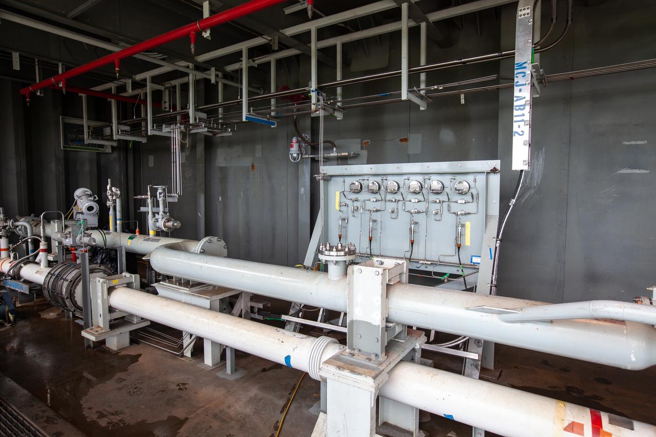
The control panel that will direct and control the flow of liquid oxygen, referred to as a skid, is photographed at Launch Pad 39B on Nov. 8, 2019, at NASA’s Kennedy Space Center in Florida. The agency’s Exploration Ground Systems oversaw testing of the pad’s cryogenic systems – the infrastructure that will support the flow of liquid hydrogen and liquid oxygen from the storage tanks, located near the pad, to the Space Launch System (SLS) rocket – in preparation for the launch of SLS with the Orion spacecraft atop for the uncrewed Artemis I mission. Each of the liquid oxygen and liquid hydrogen tanks can hold more than 800,000 gallons of propellant. The liquid oxygen will require the use of pumps to push it from the tank to the rocket, while the lighter liquid hydrogen will make its way up to the pad using gaseous hydrogen to pressurize the sphere.
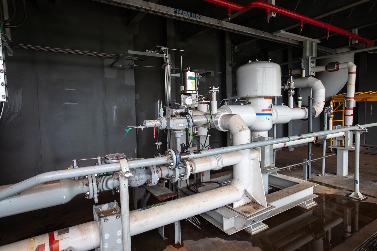
The control panel that will direct and control the flow of liquid oxygen, referred to as a skid, is photographed at Launch Pad 39B on Nov. 8, 2019, at NASA’s Kennedy Space Center in Florida. The agency’s Exploration Ground Systems oversaw testing of the pad’s cryogenic systems – the infrastructure that will support the flow of liquid hydrogen and liquid oxygen from the storage tanks, located near the pad, to the Space Launch System (SLS) rocket – in preparation for the launch of SLS with the Orion spacecraft atop for the uncrewed Artemis I mission. Each of the liquid oxygen and liquid hydrogen tanks can hold more than 800,000 gallons of propellant. The liquid oxygen will require the use of pumps to push it from the tank to the rocket, while the lighter liquid hydrogen will make its way up to the pad using gaseous hydrogen to pressurize the sphere.
In this view, liquid oxygen lines can be seen going up the mobile launcher at Launch Pad 39B on Nov. 8, 2019, at NASA’s Kennedy Space Center in Florida. The agency’s Exploration Ground Systems oversaw testing of the pad’s cryogenic systems – the infrastructure that will support the flow of liquid hydrogen and liquid oxygen from the storage tanks, located near the pad, to the Space Launch System (SLS) rocket – in preparation for the launch of SLS with the Orion spacecraft atop for the uncrewed Artemis I mission. Each of the liquid oxygen and liquid hydrogen tanks can hold more than 800,000 gallons of propellant. The liquid oxygen will require the use of pumps to push it from the tank to the rocket, while the lighter liquid hydrogen will make its way up to the pad using gaseous hydrogen to pressurize the sphere.
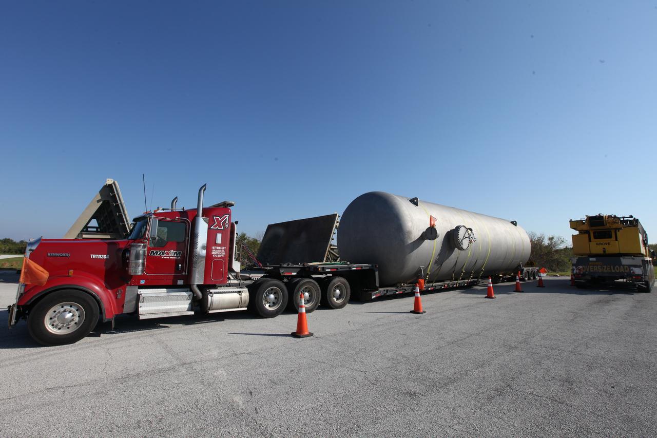
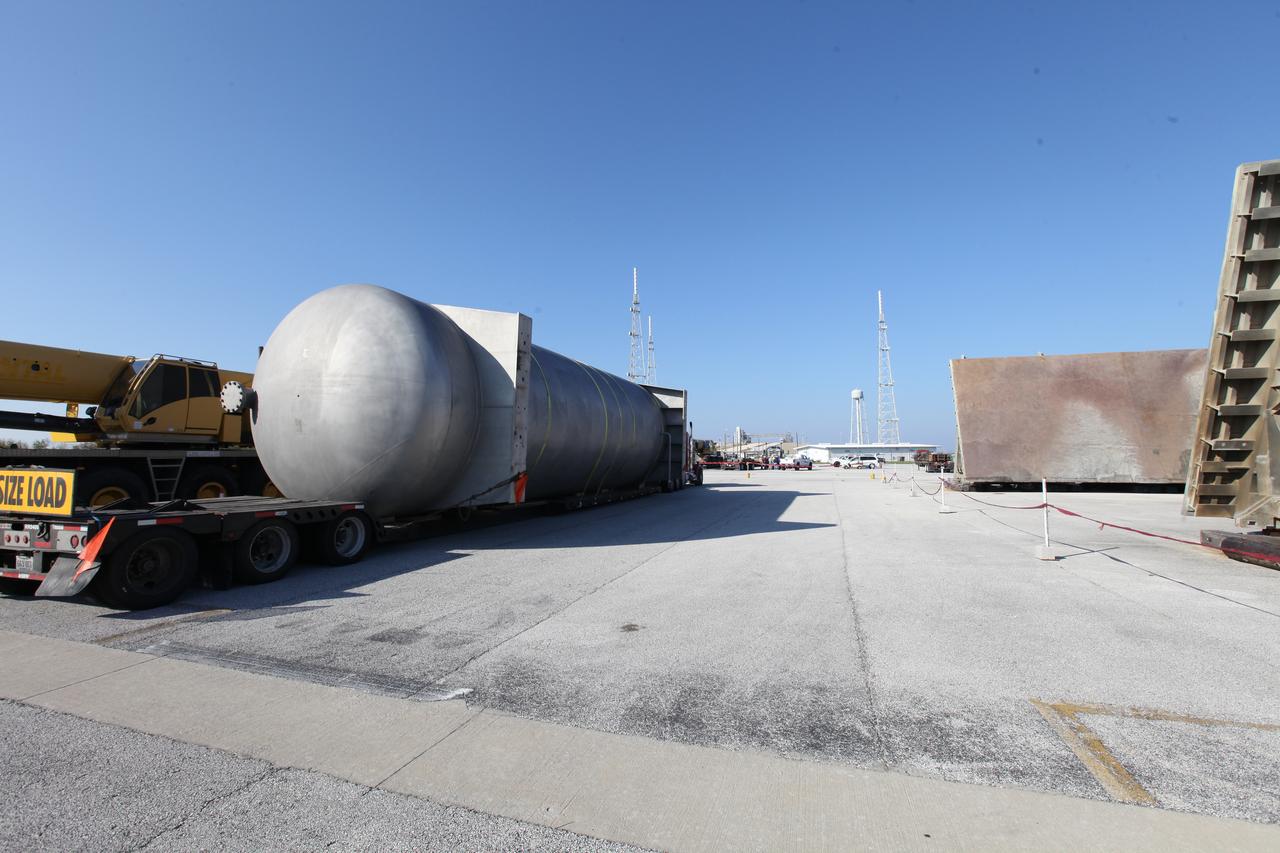
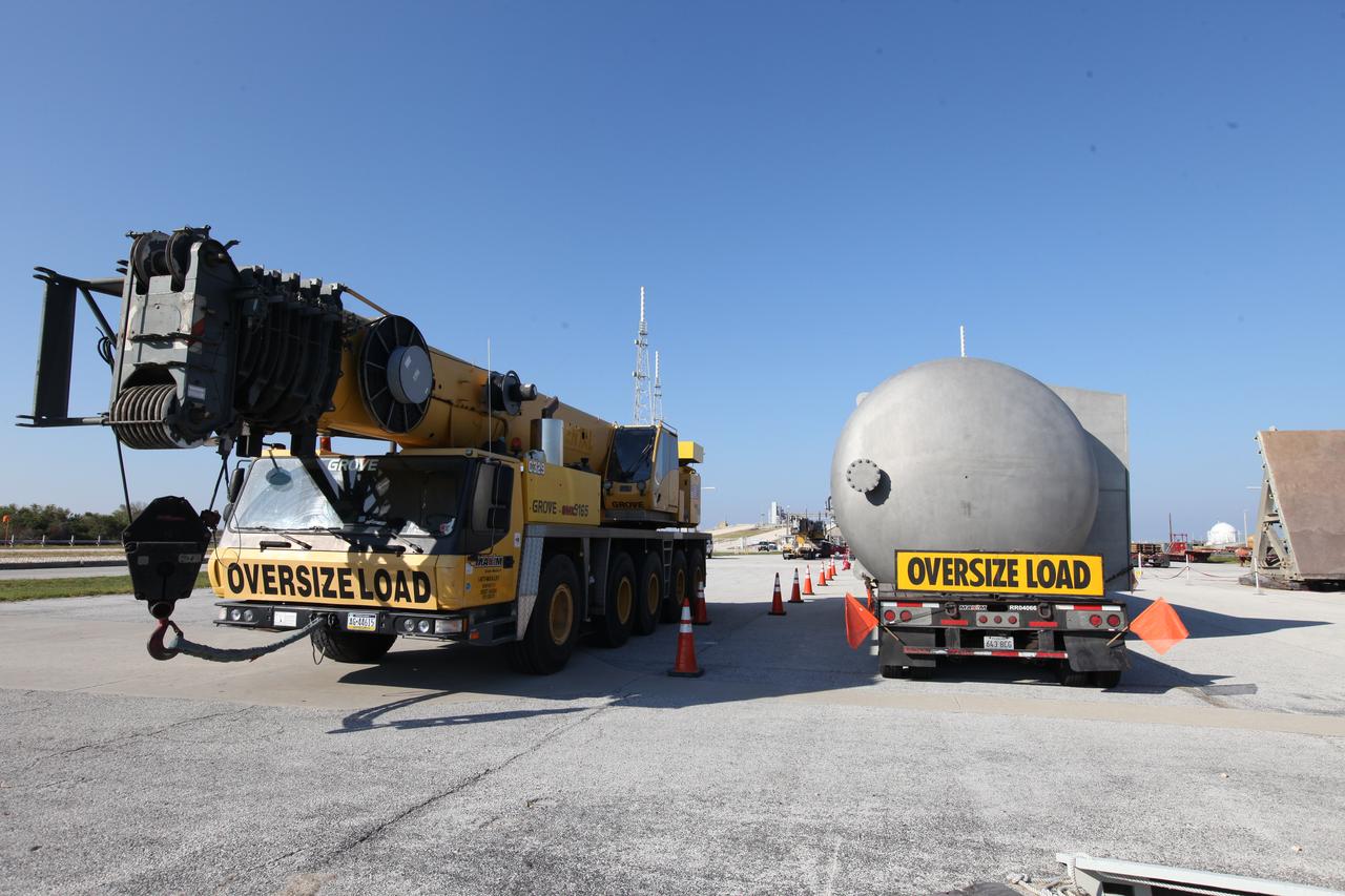
A new liquid hydrogen separator tank arrives at NASA's Kennedy Space Center in Florida. The tank will be lifted and rotated for delivery to Launch Pad 39B. The new separator/storage tank will be added to the pad's existing hydrogen vent system to assure gaseous hydrogen is delivered downstream to the flare stack. The 60,000 gallon tank was built by INOXCVA, in Baytown, Texas, a subcontractor of Precision Mechanical Inc. in Cocoa Florida. The new tank will support all future launches from the pad.
A new liquid hydrogen separator tank arrives at NASA's Kennedy Space Center in Florida. A crane will be used to lift and rotate the tank for delivery to Launch Pad 39B. The new separator/storage tank will be added to the pad's existing hydrogen vent system to assure gaseous hydrogen is delivered downstream to the flare stack. The 60,000 gallon tank was built by INOXCVA, in Baytown, Texas, a subcontractor of Precision Mechanical Inc. in Cocoa Florida. The new tank will support all future launches from the pad.
A new liquid hydrogen separator tank arrives at NASA's Kennedy Space Center in Florida. A crane has been attached to the tank to lift and rotate it before it is delivered to Launch Pad 39B. The new separator/storage tank will be added to the pad's existing hydrogen vent system to assure gaseous hydrogen is delivered downstream to the flare stack. The 60,000 gallon tank was built by INOXCVA, in Baytown, Texas, a subcontractor of Precision Mechanical Inc. in Cocoa Florida. The new tank will support all future launches from the pad.
A new liquid hydrogen separator tank arrives at NASA's Kennedy Space Center in Florida. The tank will be lifted and rotated for delivery to Launch Pad 39B. The new separator/storage tank will be added to the pad's existing hydrogen vent system to assure gaseous hydrogen is delivered downstream to the flare stack. The 60,000 gallon tank was built by INOXCVA, in Baytown, Texas, a subcontractor of Precision Mechanical Inc. in Cocoa Florida. The new tank will support all future launches from the pad.
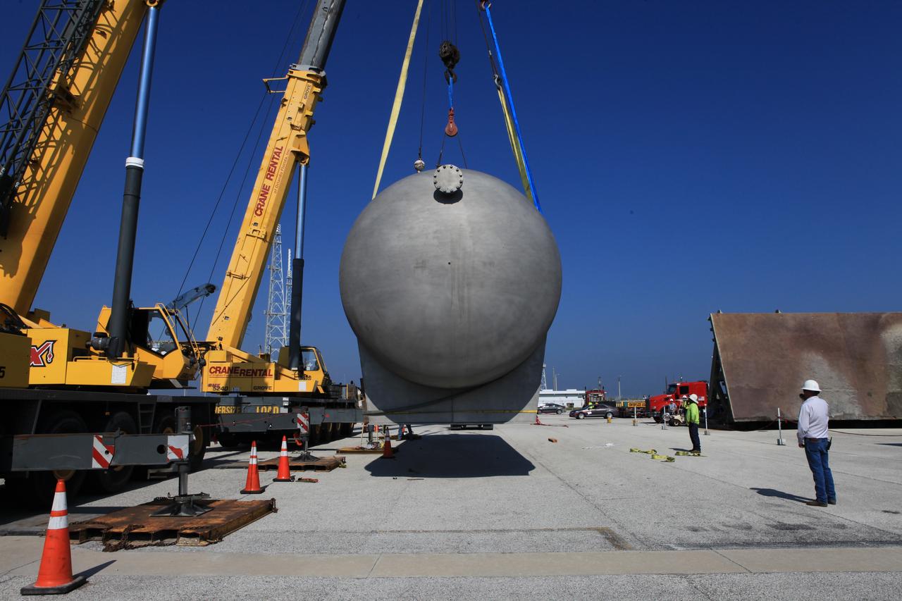
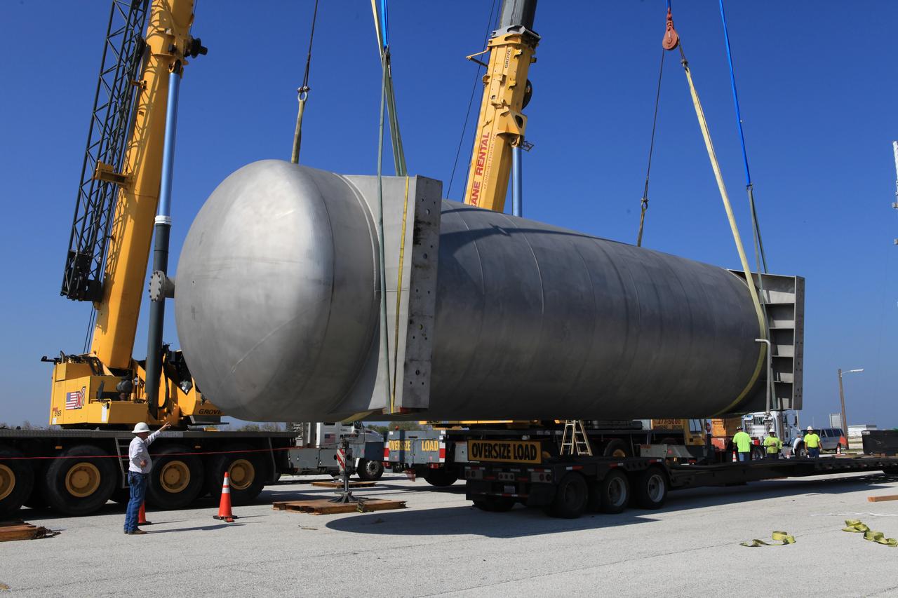
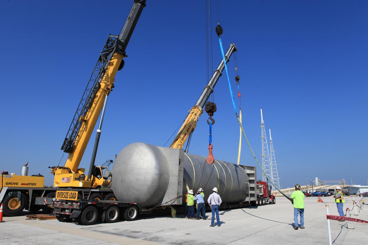
A new liquid hydrogen separator tank arrives at NASA's Kennedy Space Center in Florida. A crane is used to lift and rotate the tank before it is delivered to Launch Pad 39B. The new separator/storage tank will be added to the pad's existing hydrogen vent system to assure gaseous hydrogen is delivered downstream to the flare stack. The 60,000 gallon tank was built by INOXCVA, in Baytown, Texas, a subcontractor of Precision Mechanical Inc. in Cocoa Florida. The new tank will support all future launches from the pad.
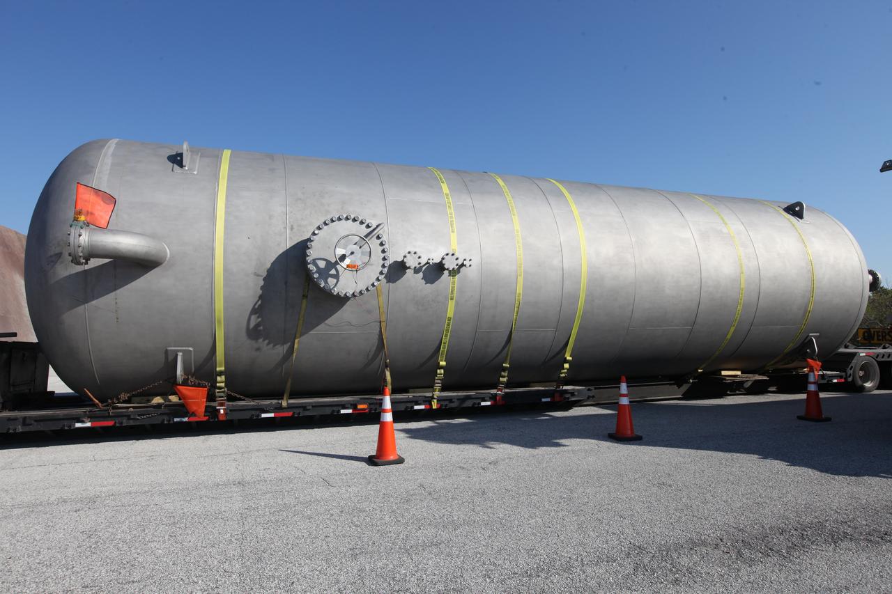
A new liquid hydrogen separator tank arrives at NASA's Kennedy Space Center in Florida. The tank will be lifted and rotated for delivery to Launch Pad 39B. The new separator/storage tank will be added to the pad's existing hydrogen vent system to assure gaseous hydrogen is delivered downstream to the flare stack. The 60,000 gallon tank was built by INOXCVA, in Baytown, Texas, a subcontractor of Precision Mechanical Inc. in Cocoa Florida. The new tank will support all future launches from the pad.
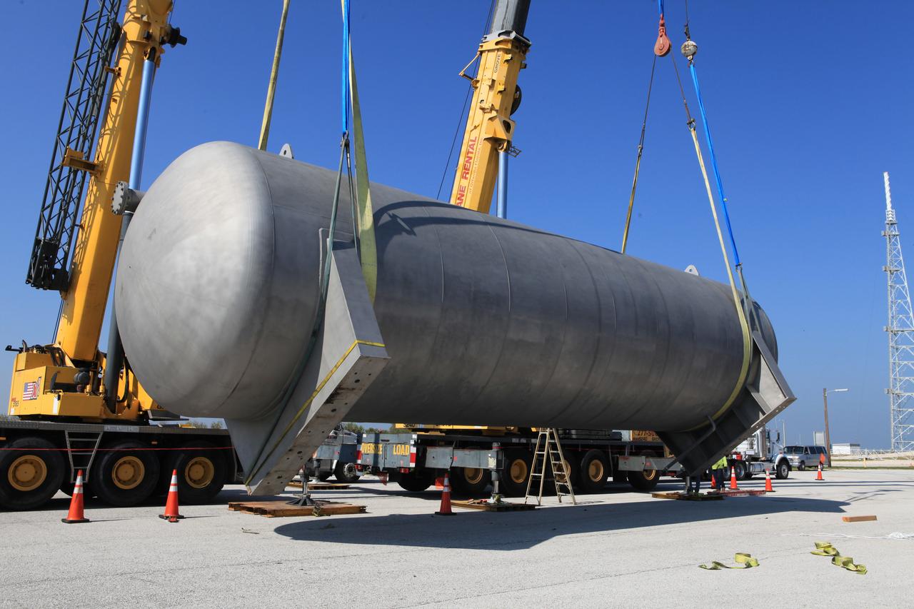
A new liquid hydrogen separator tank arrives at NASA's Kennedy Space Center in Florida. A crane is used to lift the tank and rotate it before it is delivered to Launch Pad 39B. The new separator/storage tank will be added to the pad's existing hydrogen vent system to assure gaseous hydrogen is delivered downstream to the flare stack. The 60,000 gallon tank was built by INOXCVA, in Baytown, Texas, a subcontractor of Precision Mechanical Inc. in Cocoa Florida. The new tank will support all future launches from the pad.
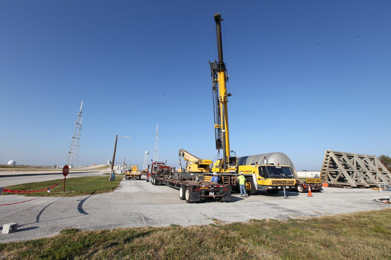
A new liquid hydrogen separator tank arrives at NASA's Kennedy Space Center in Florida. A crane will be used to lift and rotate the tank for delivery to Launch Pad 39B. The new separator/storage tank will be added to the pad's existing hydrogen vent system to assure gaseous hydrogen is delivered downstream to the flare stack. The 60,000 gallon tank was built by INOXCVA, in Baytown, Texas, a subcontractor of Precision Mechanical Inc. in Cocoa Florida. The new tank will support all future launches from the pad.
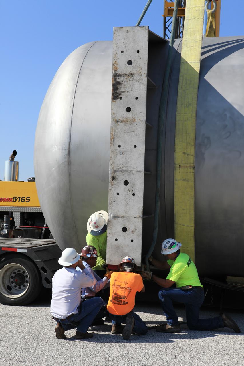
A new liquid hydrogen separator tank arrives at NASA's Kennedy Space Center in Florida. Construction workers check lines as a crane is attached to the tank to lift and rotate it before it is delivered to Launch Pad 39B. The new separator/storage tank will be added to the pad's existing hydrogen vent system to assure gaseous hydrogen is delivered downstream to the flare stack. The 60,000 gallon tank was built by INOXCVA, in Baytown, Texas, a subcontractor of Precision Mechanical Inc. in Cocoa Florida. The new tank will support all future launches from the pad.
A new liquid hydrogen separator tank arrives at NASA's Kennedy Space Center in Florida. A crane is used to lift and rotate the tank before delivery to Launch Pad 39B. The new separator/storage tank will be added to the pad's existing hydrogen vent system to assure gaseous hydrogen is delivered downstream to the flare stack. The 60,000 gallon tank was built by INOXCVA, in Baytown, Texas, a subcontractor of Precision Mechanical Inc. in Cocoa Florida. The new tank will support all future launches from the pad.
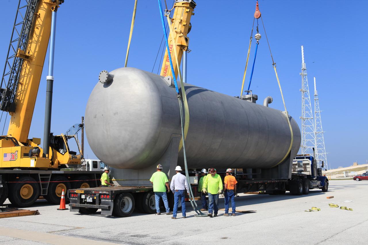
A new liquid hydrogen separator tank arrives at NASA's Kennedy Space Center in Florida. The tank has been lifted and rotated by crane and lowered back onto the flatbed truck for transport to Launch Pad 39B. The new separator/storage tank will be added to the pad's existing hydrogen vent system to assure gaseous hydrogen is delivered downstream to the flare stack. The 60,000 gallon tank was built by INOXCVA, in Baytown, Texas, a subcontractor of Precision Mechanical Inc. in Cocoa Florida. The new tank will support all future launches from the pad.
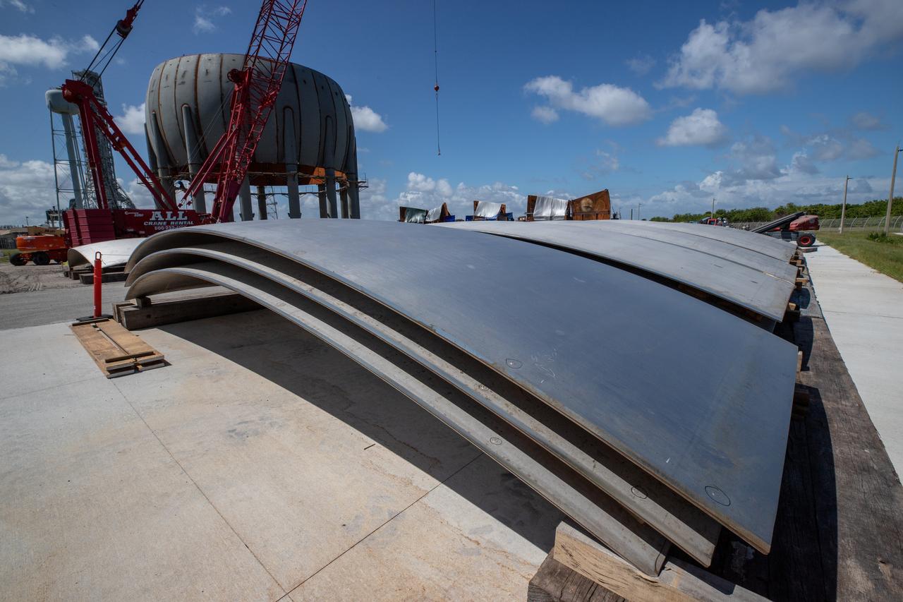
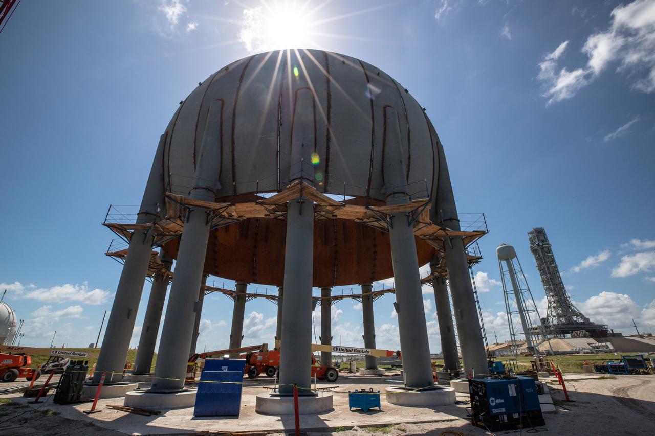
Build-up of a new liquid hydrogen (LH2) storage tank is in progress on Oct. 1, 2019, at Launch Complex 39B at NASA's Kennedy Space Center in Florida. The new tank will hold 1.25 million gallons of usable LH2 to support future launches from the pad, including Artemis missions to the Moon and on to Mars.
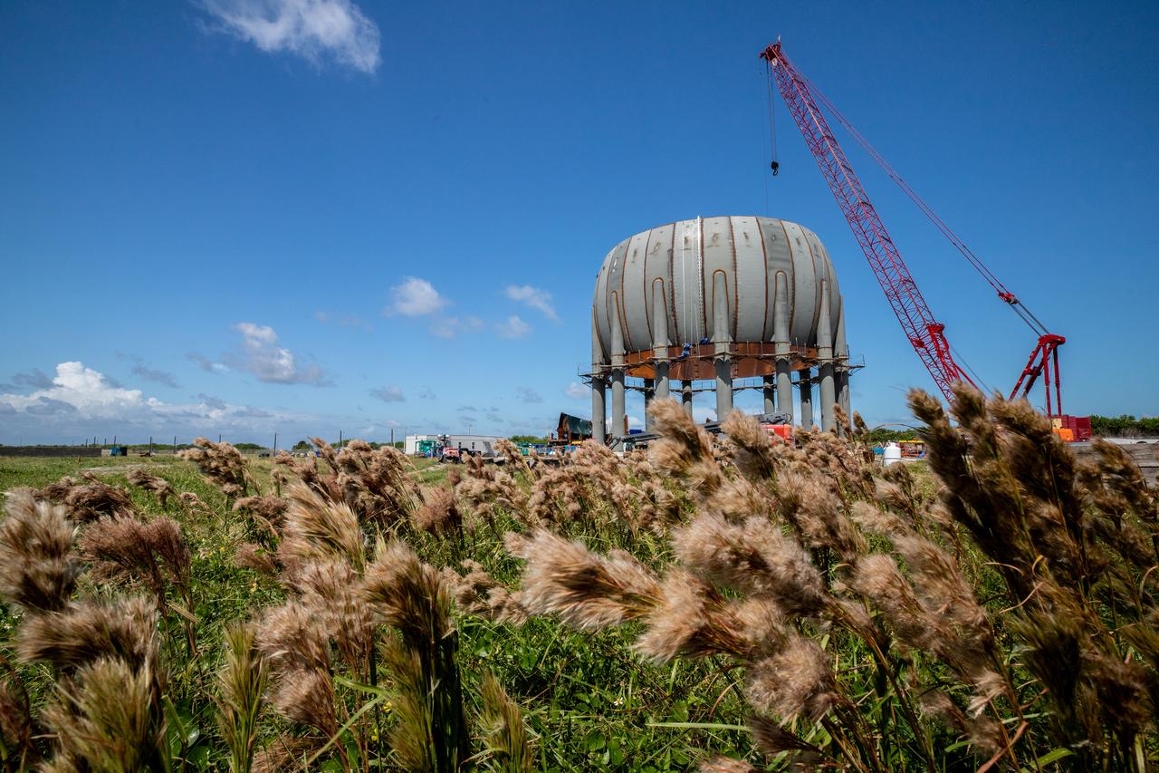
Build-up of a new liquid hydrogen (LH2) storage tank is in progress on Oct. 1, 2019, at Launch Complex 39B at NASA's Kennedy Space Center in Florida. The new tank will hold 1.25 million gallons of usable LH2 to support future launches from the pad, including Artemis missions to the Moon and on to Mars.
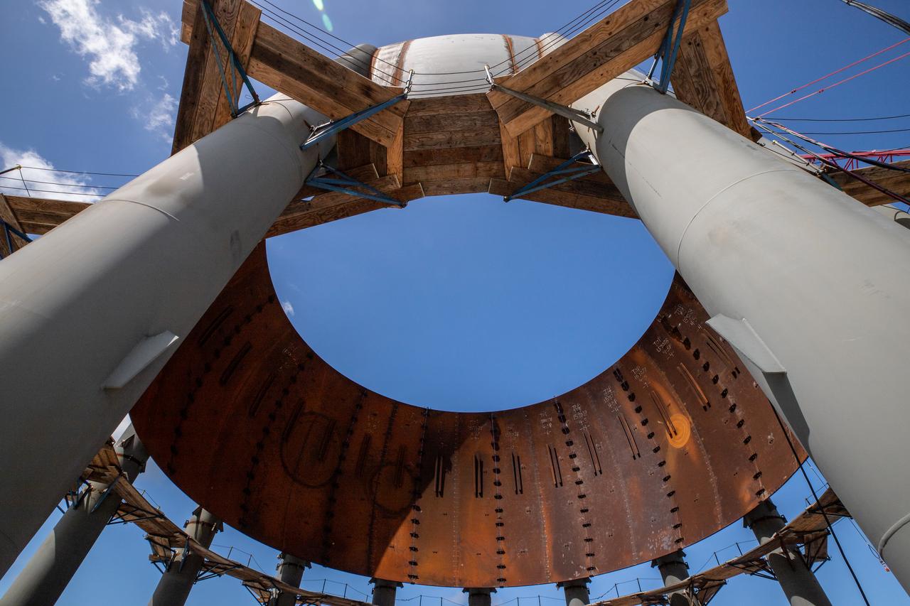
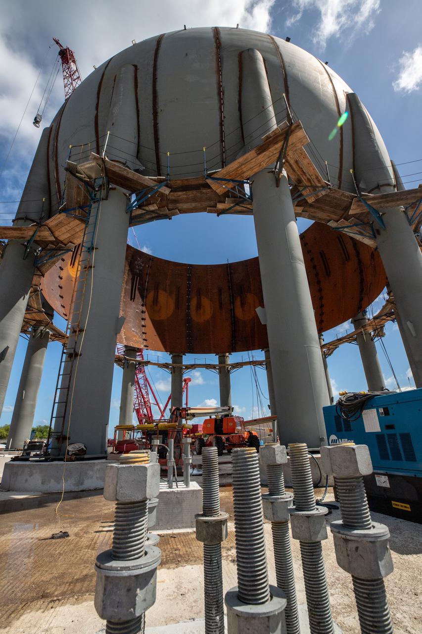
Build-up of a new liquid hydrogen (LH2) storage tank is in progress on Oct. 1, 2019, at Launch Complex 39B at NASA's Kennedy Space Center in Florida. The new tank will hold 1.25 million gallons of usable LH2 to support future launches from the pad, including Artemis missions to the Moon and on to Mars.
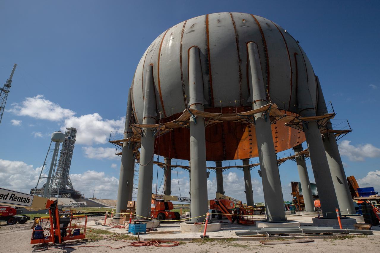
Build-up of a new liquid hydrogen (LH2) storage tank is in progress on Oct. 1, 2019, at Launch Complex 39B at NASA's Kennedy Space Center in Florida. The new tank will hold 1.25 million gallons of usable LH2 to support future launches from the pad, including Artemis missions to the Moon and on to Mars.
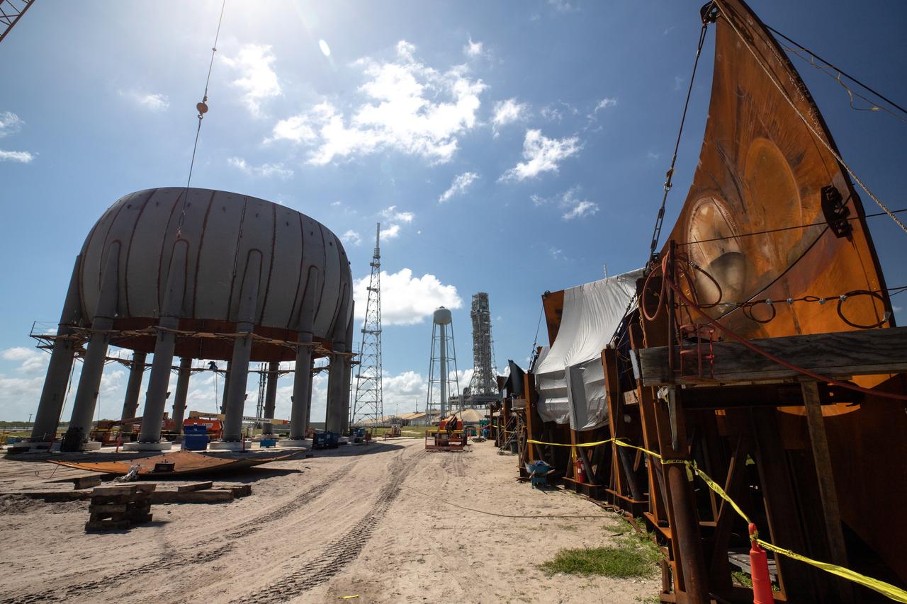
Build-up of a new liquid hydrogen (LH2) storage tank is in progress on Oct. 1, 2019, at Launch Complex 39B at NASA's Kennedy Space Center in Florida. The new tank will hold 1.25 million gallons of usable LH2 to support future launches from the pad, including Artemis missions to the Moon and on to Mars.
Build-up of a new liquid hydrogen (LH2) storage tank is in progress on Oct. 1, 2019, at Launch Complex 39B at NASA's Kennedy Space Center in Florida. The new tank will hold 1.25 million gallons of usable LH2 to support future launches from the pad, including Artemis missions to the Moon and on to Mars.
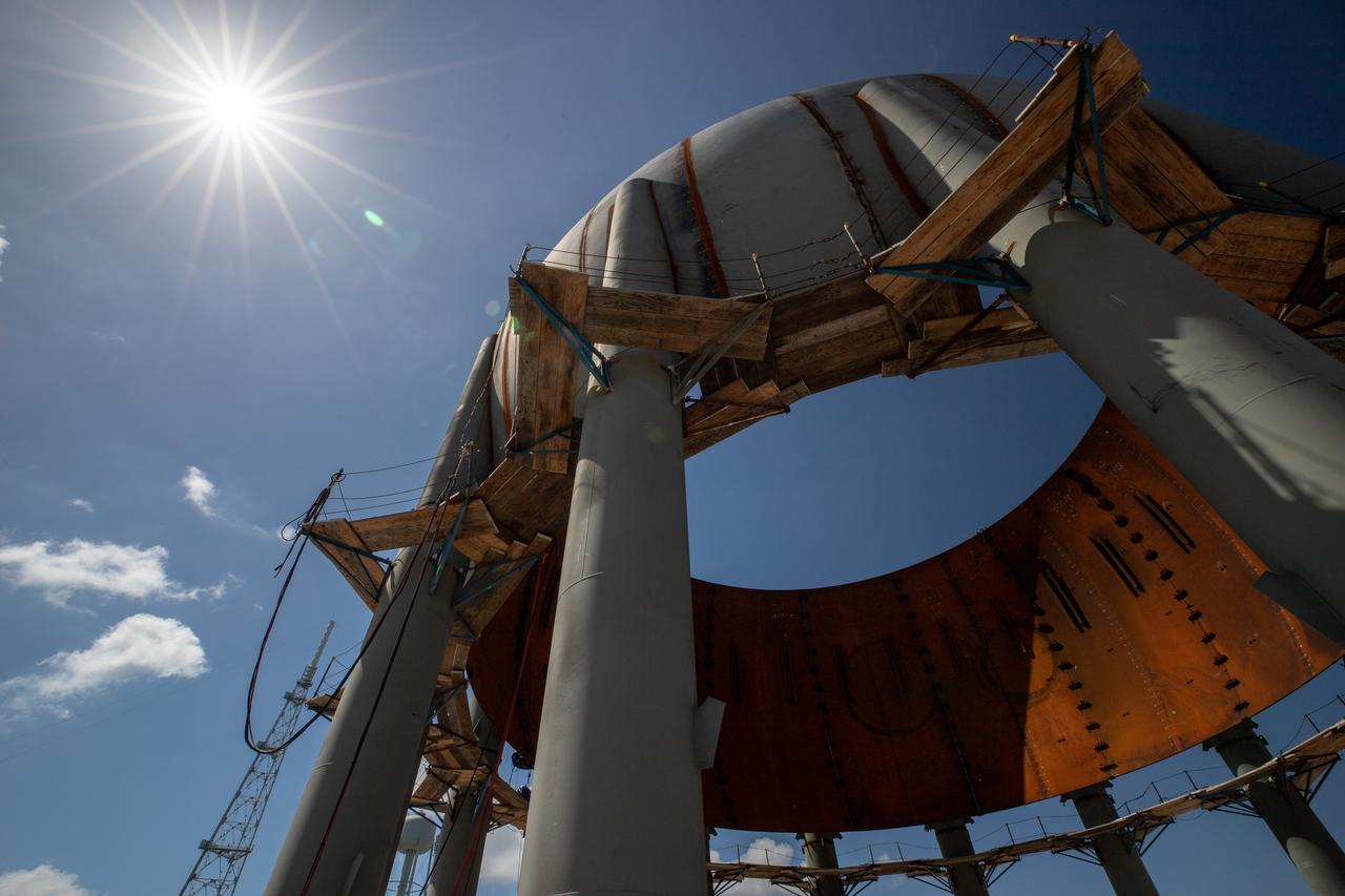
Build-up of a new liquid hydrogen (LH2) storage tank is in progress on Oct. 1, 2019, at Launch Complex 39B at NASA's Kennedy Space Center in Florida. The new tank will hold 1.25 million gallons of usable LH2 to support future launches from the pad, including Artemis missions to the Moon and on to Mars.
Build-up of a new liquid hydrogen (LH2) storage tank is in progress on Oct. 1, 2019, at Launch Complex 39B at NASA's Kennedy Space Center in Florida. The new tank will hold 1.25 million gallons of usable LH2 to support future launches from the pad, including Artemis missions to the Moon and on to Mars.
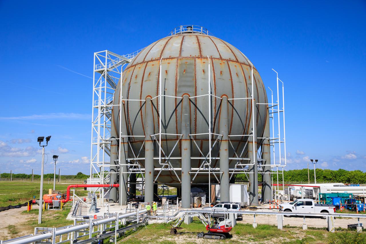
Seen here is a newly constructed liquid hydrogen (LH2) storage tank at Launch Pad 39B at NASA’s Kennedy Space Center in Florida on Oct. 1, 2021. With construction now complete, teams will focus on painting the tank next. The storage tank, capable of holding 1.25 million gallons of LH2, will be used to support future Artemis missions to the Moon and, eventually, Mars. Through Artemis, NASA will land the first woman and first person of color on the Moon, paving the way for a long-term presence in lunar orbit.
Seen here is a newly constructed liquid hydrogen (LH2) storage tank at Launch Pad 39B at NASA’s Kennedy Space Center in Florida on Oct. 1, 2021. With construction now complete, teams will focus on painting the tank next. The storage tank, capable of holding 1.25 million gallons of LH2, will be used to support future Artemis missions to the Moon and, eventually, Mars. Through Artemis, NASA will land the first woman and first person of color on the Moon, paving the way for a long-term presence in lunar orbit.
Seen here is a newly constructed liquid hydrogen (LH2) storage tank at Launch Pad 39B at NASA’s Kennedy Space Center in Florida on Oct. 1, 2021. With construction now complete, teams will focus on painting the tank next. The storage tank, capable of holding 1.25 million gallons of LH2, will be used to support future Artemis missions to the Moon and, eventually, Mars. Through Artemis, NASA will land the first woman and first person of color on the Moon, paving the way for a long-term presence in lunar orbit.
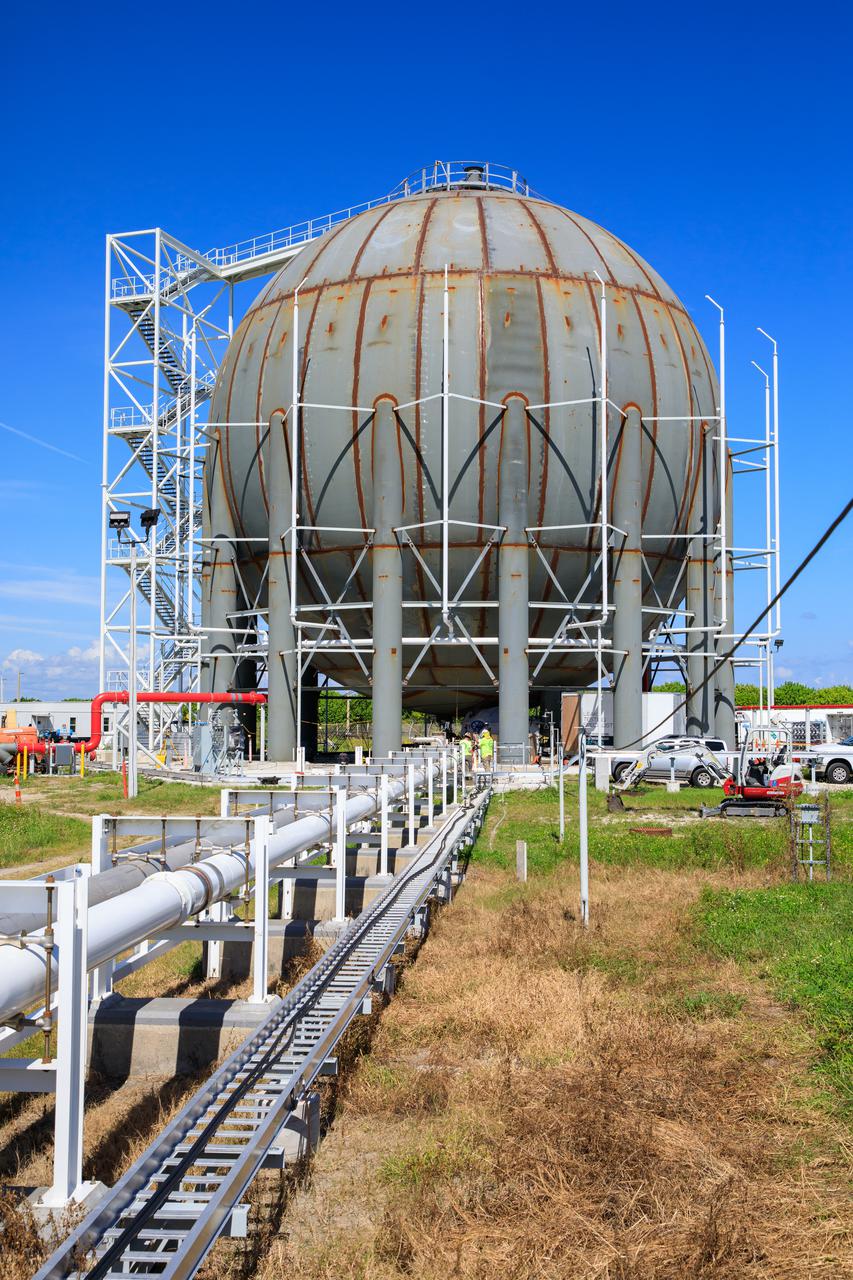
Seen here is a newly constructed liquid hydrogen (LH2) storage tank at Launch Pad 39B at NASA’s Kennedy Space Center in Florida on Oct. 1, 2021. With construction now complete, teams will focus on painting the tank next. The storage tank, capable of holding 1.25 million gallons of LH2, will be used to support future Artemis missions to the Moon and, eventually, Mars. Through Artemis, NASA will land the first woman and first person of color on the Moon, paving the way for a long-term presence in lunar orbit.
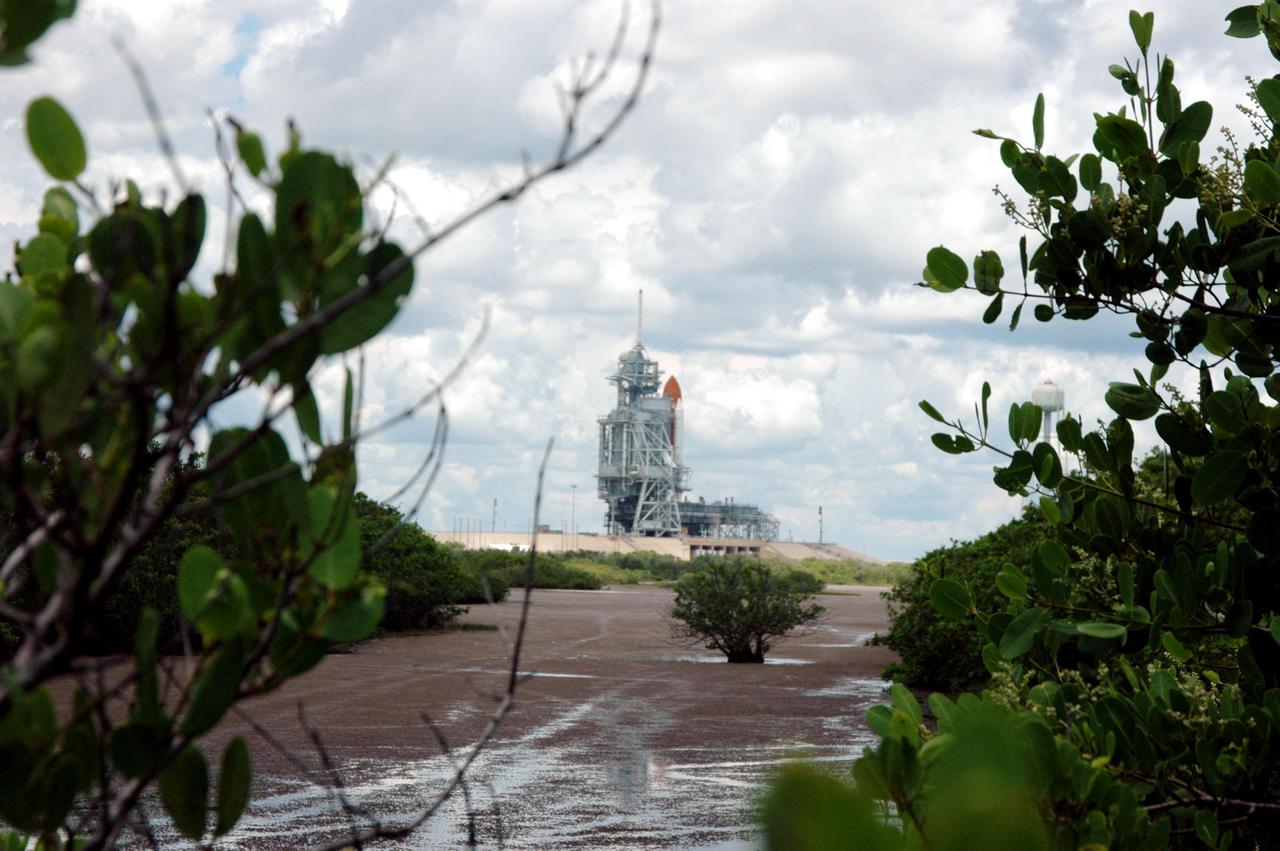
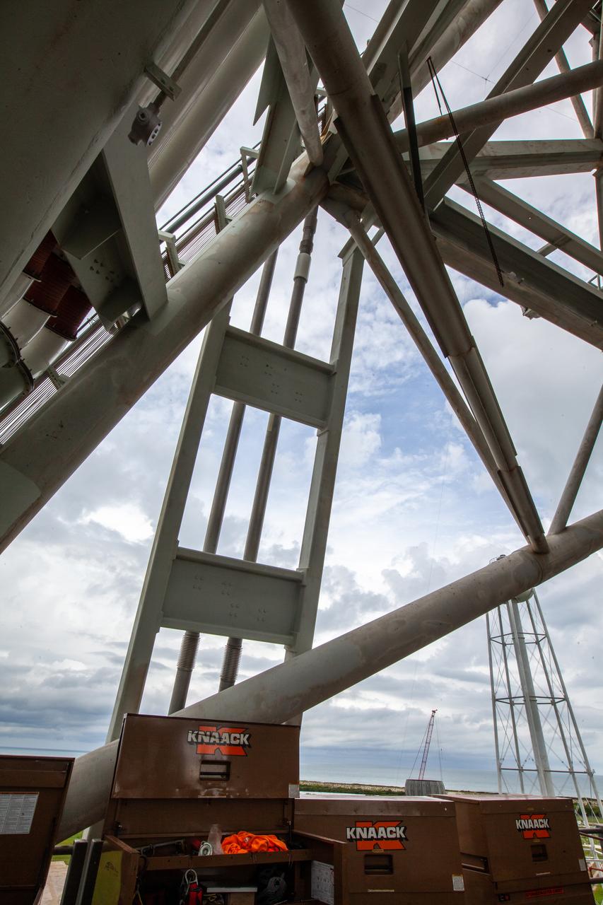
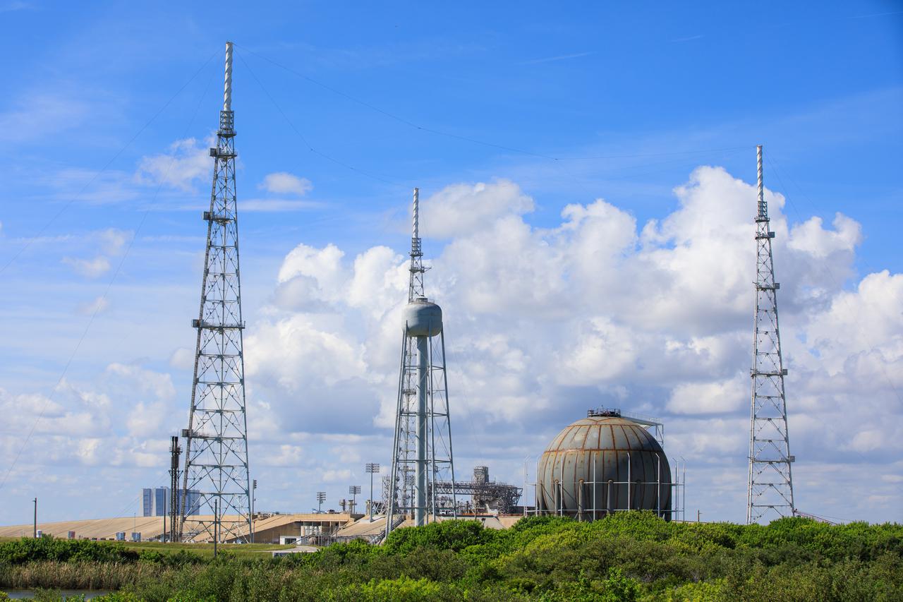
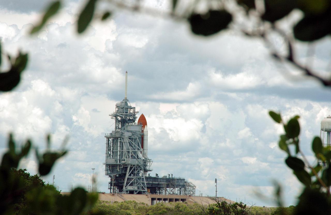
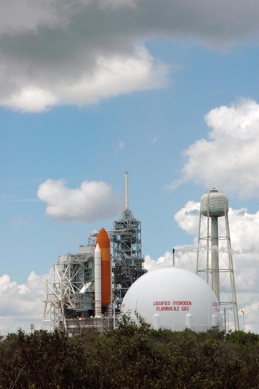
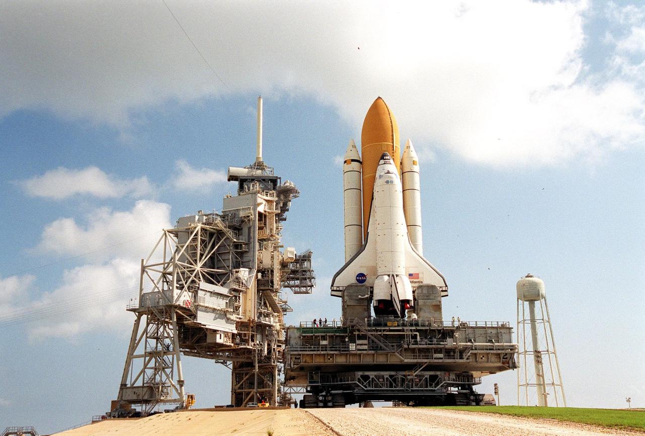
KENNEDY SPACE CENTER, FLA. - Space Shuttle Discovery remains on the pad the day after the Shuttle’s launch on Return to Flight mission STS-114 was scrubbed. In the foreground is the liquid hydrogen storage tank. At right is the 290-foot-tall water tower that holds 300,000 gallons of water, part of the sound suppression system during a launch. The July 13 mission was scrubbed when a low-level fuel cut-off sensor for the liquid hydrogen tank inside the External Tank failed a routine prelaunch check during the countdown July 13, causing mission managers to scrub Discovery's first launch attempt. The sensor protects the Shuttle's main engines by triggering their shutdown in the event fuel runs unexpectedly low. The sensor is one of four inside the liquid hydrogen section of the External Tank (ET).
KENNEDY SPACE CENTER, FLA. - Space Shuttle Discovery remains on the pad the day after the Shuttle’s launch on Return to Flight mission STS-114 was scrubbed. In the foreground is the liquid hydrogen storage tank. At right is the 290-foot-tall water tower that holds 300,000 gallons of water, part of the sound suppression system during a launch. The July 13 mission was scrubbed when a low-level fuel cut-off sensor for the liquid hydrogen tank inside the External Tank failed a routine prelaunch check during the countdown July 13, causing mission managers to scrub Discovery's first launch attempt. The sensor protects the Shuttle's main engines by triggering their shutdown in the event fuel runs unexpectedly low. The sensor is one of four inside the liquid hydrogen section of the External Tank (ET).
KENNEDY SPACE CENTER, FLA. - Space Shuttle Discovery remains on the pad the day after the Shuttle’s launch on Return to Flight mission STS-114 was scrubbed. In the foreground is the liquid hydrogen storage tank. At right is the 290-foot-tall water tower that holds 300,000 gallons of water, part of the sound suppression system during a launch. The July 13 mission was scrubbed when a low-level fuel cut-off sensor for the liquid hydrogen tank inside the External Tank failed a routine prelaunch check during the countdown July 13, causing mission managers to scrub Discovery's first launch attempt. The sensor protects the Shuttle's main engines by triggering their shutdown in the event fuel runs unexpectedly low. The sensor is one of four inside the liquid hydrogen section of the External Tank (ET).
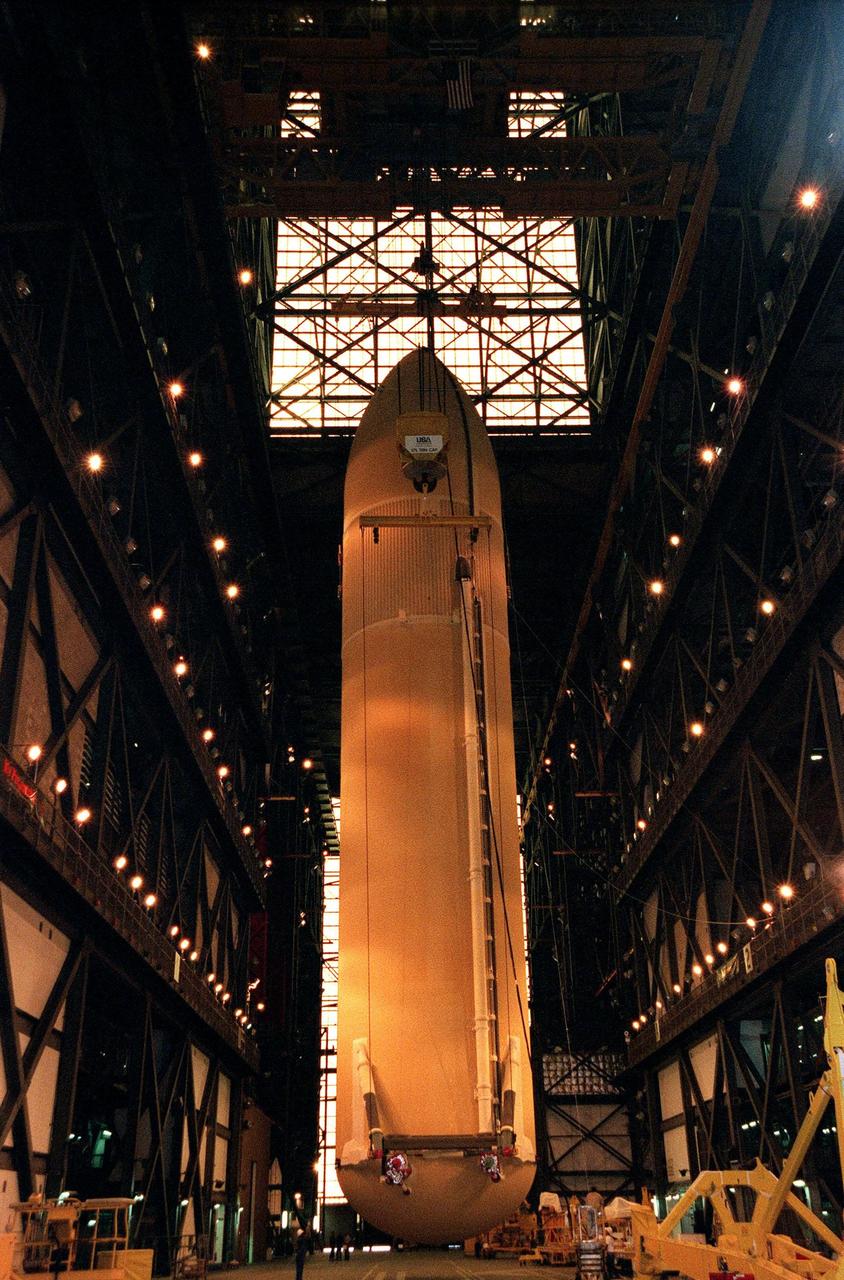
KENNEDY SPACE CENTER, FLA. -- An external tank is suspended in the transfer aisle of the Vehicle Assembly Building before being placed into its storage compartment. The largest and heaviest element of the Space Shuttle, an external tank contains the liquid hydrogen fuel and liquid oxygen oxidizer for the three Space Shuttle main engines (SSMEs) in the orbiter during liftoff and ascent. When the SSMEs are shut down, the external tank is jettisoned, breaking up as it enters the Earth's atmopshere and impacting in a remote ocean area. It is not recovered
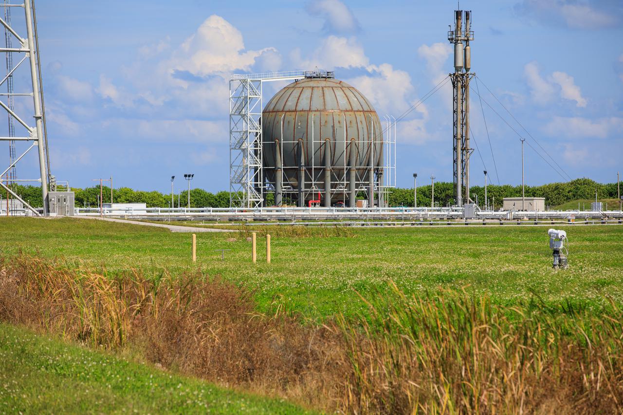
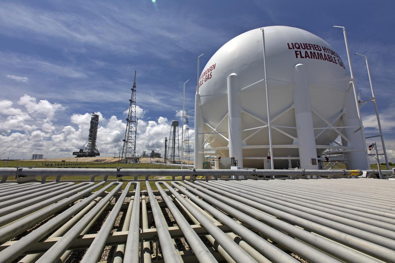
CAPE CANAVERAL, Fla. -- In the Launch Complex 39 area at NASA's Kennedy Space Center in Florida is a liquid hydrogen, or LH2, storage tank. This large ball-shaped, vacuum-jacketed tank is used to store cryogenic propellants for the space shuttle's orange external fuel tank. The LH2 tank is located at the northeast corner of Launch Pad 39A and stores 850,000 gallons of LH2 at a temperature of minus 423 degrees F. The shuttle's external tank is loaded with about 500,000 gallons of LH2 and liquid oxygen, or LOX, about six hours prior to launch in a process known as 'tanking.' Photo credit: NASA_Frankie Martin
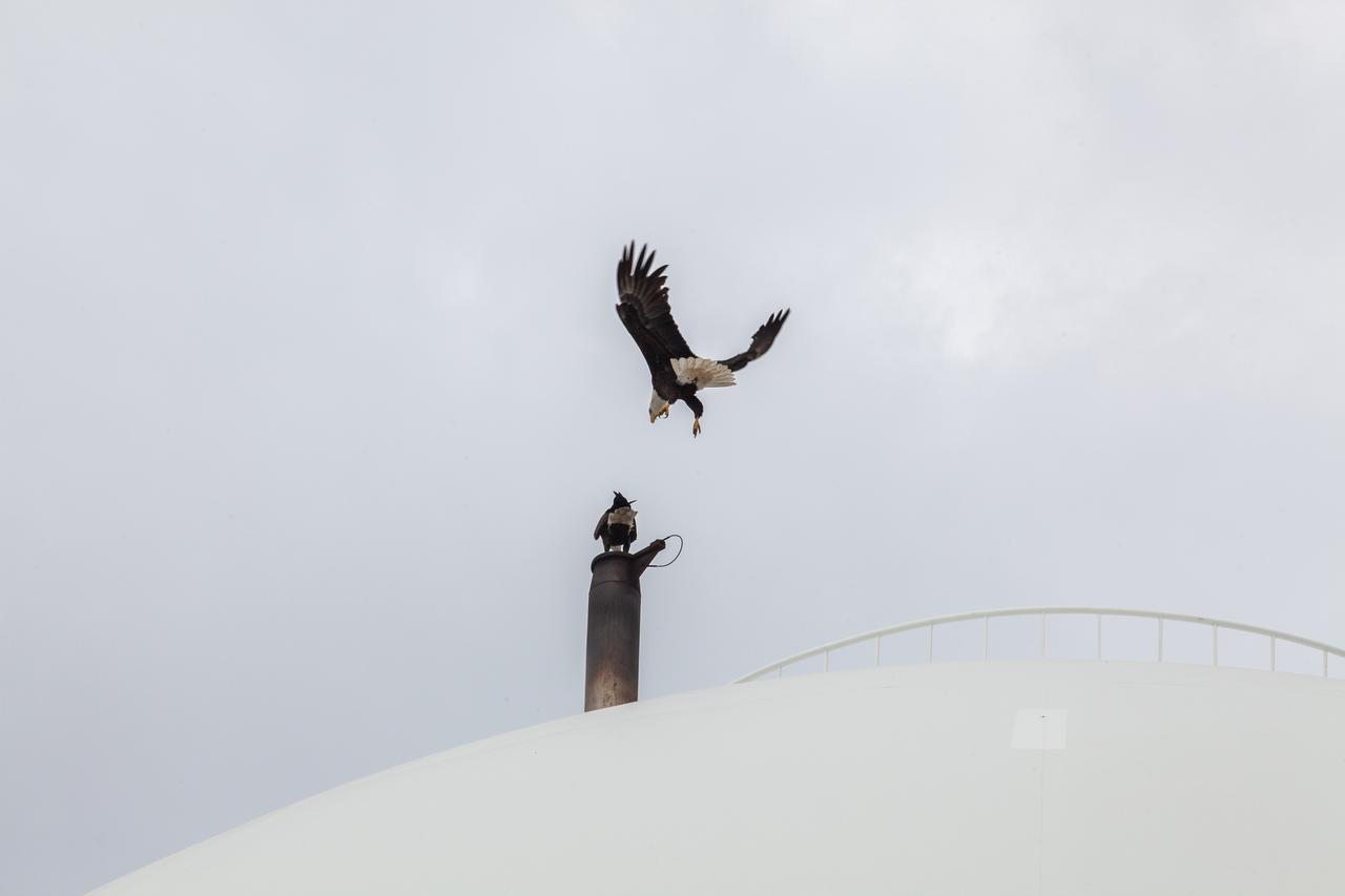
A bald eagle approaches the liquid hydrogen storage tank at Launch Pad 39B on Nov. 8, 2019, at NASA’s Kennedy Space Center in Florida. Kennedy shares a border with the Merritt Island National Wildlife Refuge, consisting of 144,000 acres of land, water and marshes. Many species of birds, reptiles, fish, amphibians and mammals can be found within the refuge.

On Dec. 19, 2018, Bill Hill, deputy associate administrator for Exploration Systems Development at NASA Headquarters in Washington, speaks during a groundbreaking ceremony for a new liquid hydrogen tank for Launch Complex 39B at the agency's Kennedy Space Center. The storage facility will hold 1.25 million gallons of the propellant for NASA's Space Launch System rocket designed to boost the agency's Orion spacecraft, sending humans to distant destinations such as the Moon and Mars.
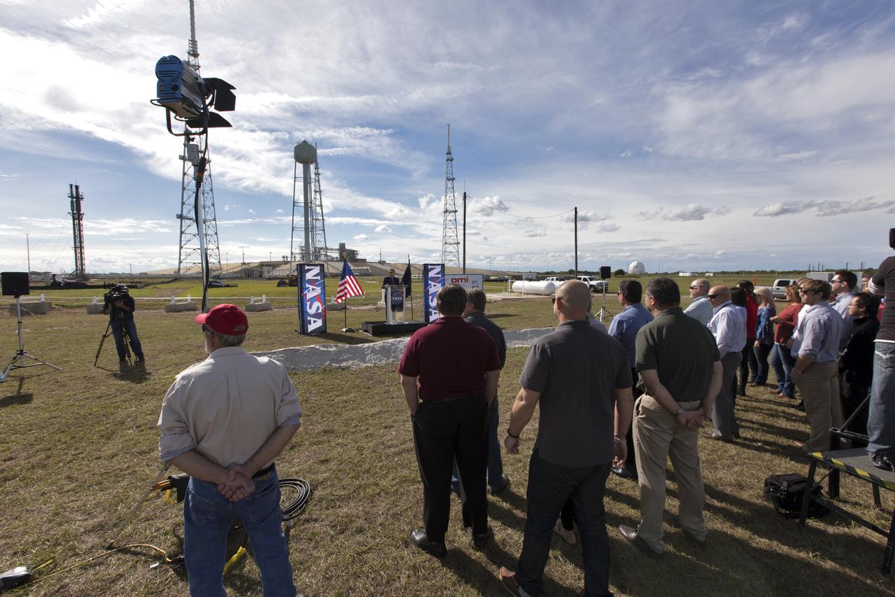
On Dec. 19, 2018, NASA and contractor managers gathered for a groundbreaking ceremony for a new liquid hydrogen tank for Launch Complex 39B at NASA's Kennedy Space Center. The storage facility will hold 1.25 million gallons of the propellant for NASA's Space Launch System rocket designed to boost the agency's Orion spacecraft, sending humans to distant destinations such as the Moon and Mars.
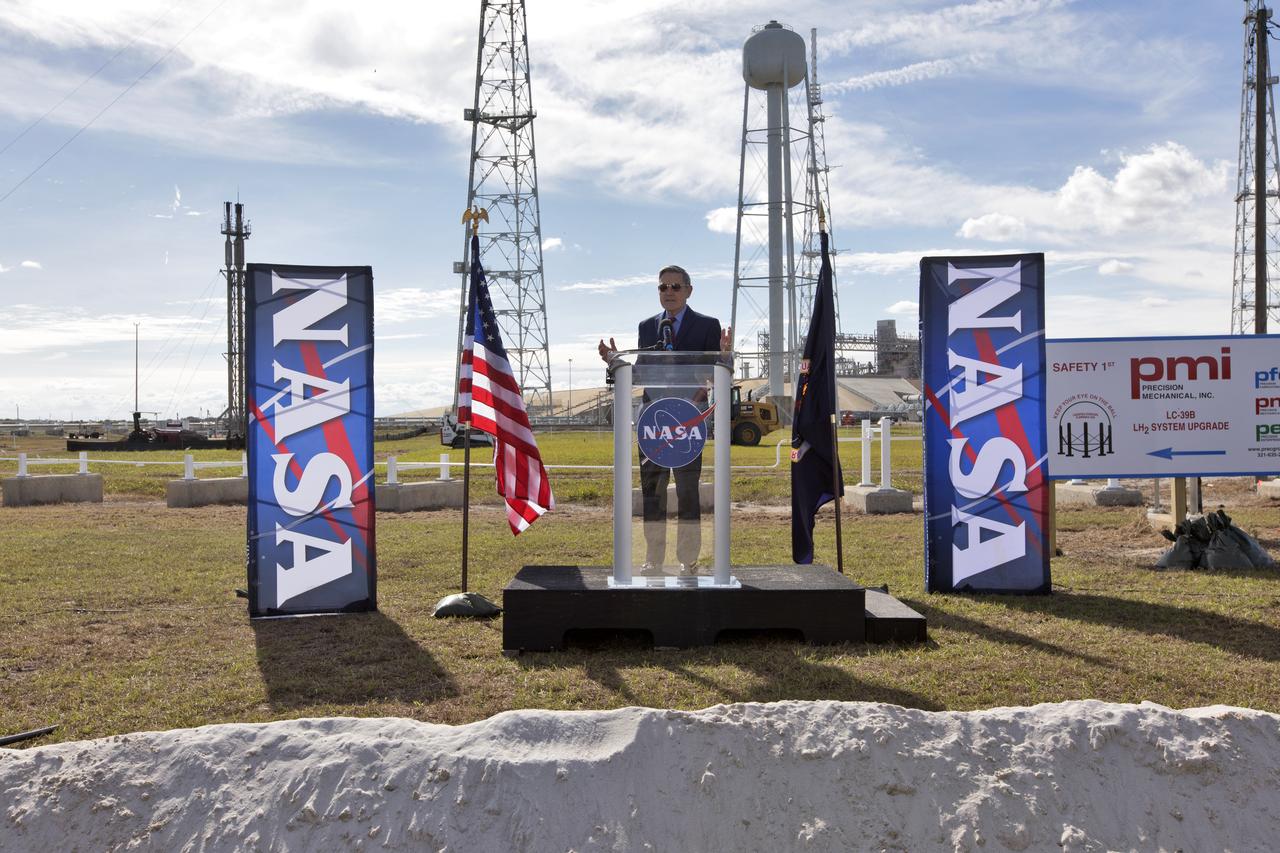
On Dec. 19, 2018, Kennedy Space Center Director Bob Cabana speaks during a groundbreaking ceremony for a new liquid hydrogen tank for Launch Complex 39B at the space center. The storage facility will hold 1.25 million gallons of the propellant for NASA's Space Launch System rocket designed to boost the agency's Orion spacecraft, sending humans to distant destinations such as the Moon and Mars.

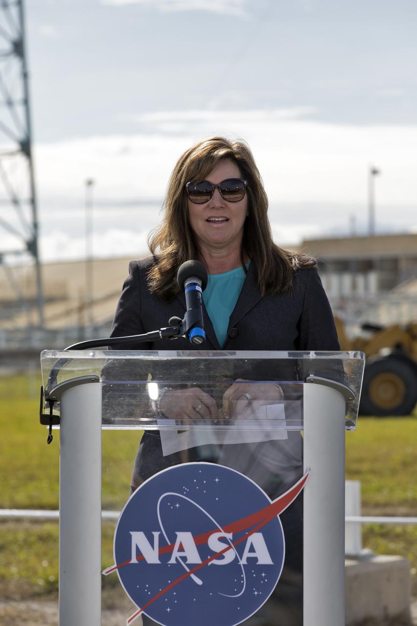
On Dec. 19, 2018, NASA Launch Director Charlie Blackwell-Thompson speaks during a groundbreaking ceremony for a new liquid hydrogen tank for Launch Complex 39B at the agency's Kennedy Space Center. The storage facility will hold 1.25 million gallons of the propellant for NASA's Space Launch System rocket designed to boost the agency's Orion spacecraft, sending humans to distant destinations such as the Moon and Mars.
On Dec. 19, 2018, Jennifer Kunz, deputy program manager for Exploration Ground Systems, speaks during a groundbreaking ceremony for a new liquid hydrogen tank for Launch Complex 39B at the agency's Kennedy Space Center. The storage facility will hold 1.25 million gallons of the propellant for NASA's Space Launch System rocket designed to boost the agency's Orion spacecraft, sending humans to distant destinations such as the Moon and Mars.
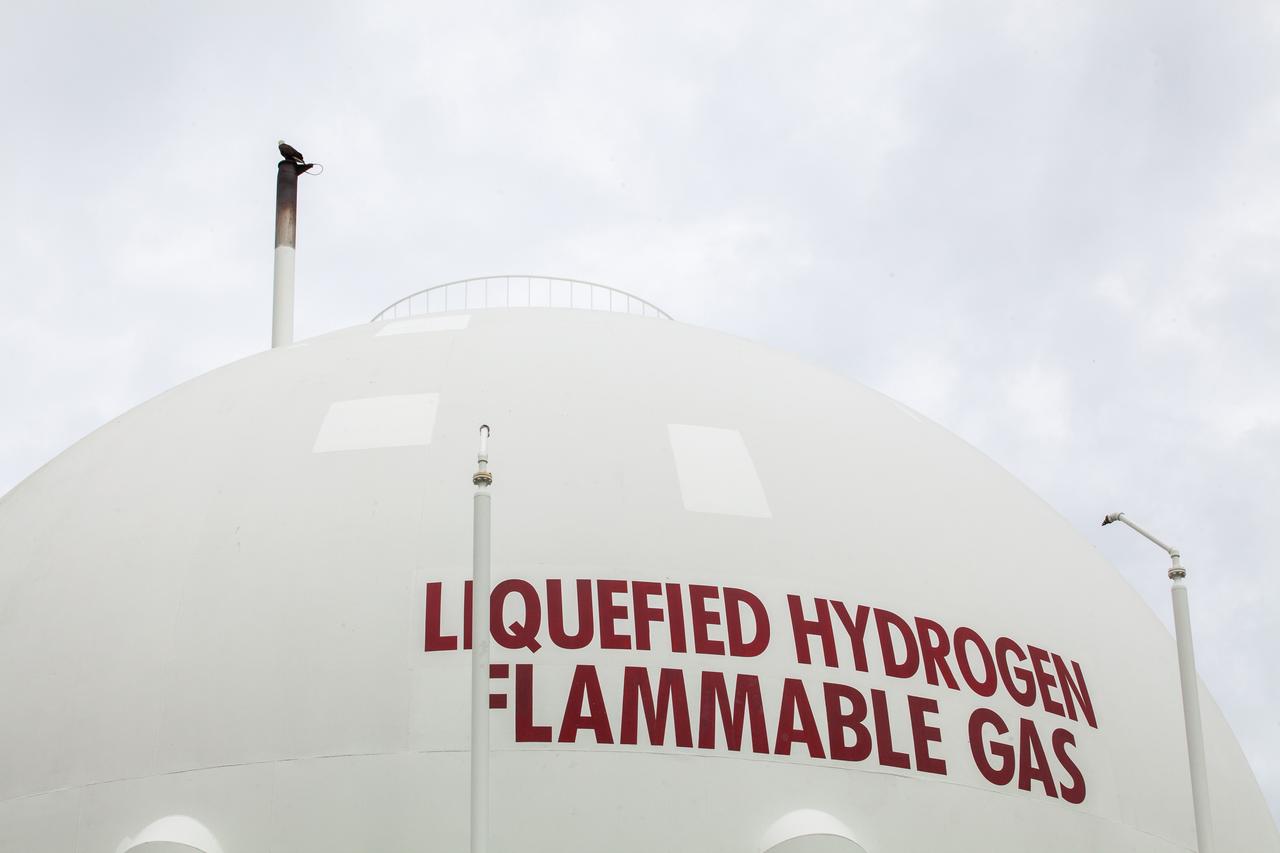
A bald eagle perches on the liquid hydrogen storage tank at Launch Pad 39B on Nov. 8, 2019, at NASA’s Kennedy Space Center in Florida. Kennedy shares a border with the Merritt Island National Wildlife Refuge, consisting of 144,000 acres of land, water and marshes. Many species of birds, reptiles, fish, amphibians and mammals can be found within the refuge.

A bald eagle perches on the liquid hydrogen storage tank at Launch Pad 39B on Nov. 8, 2019, at NASA’s Kennedy Space Center in Florida. Kennedy shares a border with the Merritt Island National Wildlife Refuge, consisting of 144,000 acres of land, water and marshes. Many species of birds, reptiles, fish, amphibians and mammals can be found within the refuge.
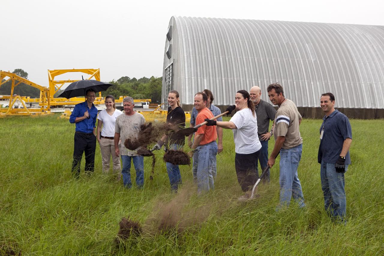
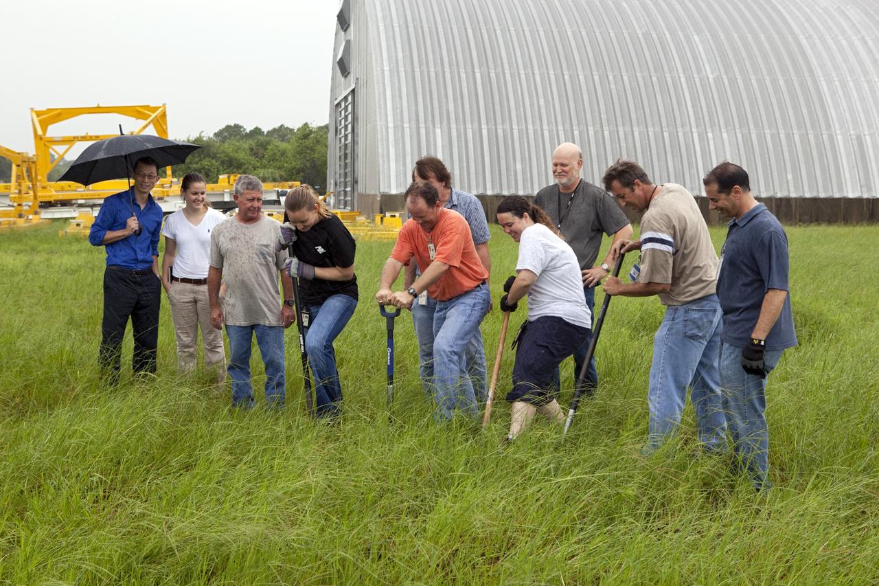
CAPE CANAVERAL, Fla. – Near the Hypergolic Maintenance Facility at NASA’s Kennedy Space Center in Florida, a groundbreaking ceremony was held to mark the location of the Ground Operations Demonstration Unit Liquid Hydrogen, or GODU LH2, test site. From left, are Johnny Nguyen, Fluids Test and Technology Development branch chief Emily Watkins, engineering intern Jeff Walls, Engineering Services Contract, or ESC, Cryogenics Test Lab engineer Kelly Currin, systems engineer Stephen Huff and Rudy Werlink partially hidden, cryogenics engineers Angela Krenn, systems engineer Doug Hammond, command and control engineer in the electrical division William Notardonato, GODU LH2 project manager and Kevin Jumper, ESC Cryogenics Test Lab manager. The GODU LH2 test site is one of the projects in NASA’s Advanced Exploration Systems Program. The site will be used to demonstrate advanced liquid hydrogen systems that are cost and energy efficient ways to store and transfer liquid hydrogen during process, loading, launch and spaceflight. The main components of the site will be a storage tank and a cryogenic refrigerator. Photo credit: NASA/Dimitri Gerondidakis
CAPE CANAVERAL, Fla. – Near the Hypergolic Maintenance Facility at NASA’s Kennedy Space Center in Florida, a groundbreaking ceremony was held to mark the location of the Ground Operations Demonstration Unit Liquid Hydrogen, or GODU LH2, test site. From left, are Johnny Nguyen, Fluids Test and Technology Development branch chief Emily Watkins, engineering intern Jeff Walls, Engineering Services Contract, or ESC, Cryogenics Test Lab engineer Kelly Currin, systems engineer Stephen Huff and Rudy Werlink partially hidden, cryogenics engineers Angela Krenn, systems engineer Doug Hammond, command and control engineer in the electrical division William Notardonato, GODU LH2 project manager and Kevin Jumper, ESC Cryogenics Test Lab manager. The GODU LH2 test site is one of the projects in NASA’s Advanced Exploration Systems Program. The site will be used to demonstrate advanced liquid hydrogen systems that are cost and energy efficient ways to store and transfer liquid hydrogen during process, loading, launch and spaceflight. The main components of the site will be a storage tank and a cryogenic refrigerator. Photo credit: NASA/Dimitri Gerondidakis

Replicas of Christopher Columbus' sailing ships Santa Maria, Nina, and Pinta sail by Endeavour, Orbiter Vehicle (OV) 105, on Kennedy Space Center (KSC) Launch Complex (LC) Pad 39B awaiting liftoff on its maiden voyage, STS-49. This view was taken from the water showing the three ships silhouetted in the foreground with OV-105 on mobile launcher platform profiled against fixed service structure (FSS) tower and rectracted rotating service structure (RSS) in the background. Next to the launch pad (at right) are the sound suppression water system tower and the liquid hydrogen (LH2) storage tank. View provided by KSC with alternate number KSC-92PC-970.
A liquid hydrogen storage tank is in view as NASA's mobile launcher (ML) atop crawler-transporter 2 makes its way up the ramp at Launch Pad 39B on Aug. 31, 2018, at the agency's Kennedy Space Center in Florida. The ML will undergo a fit check, followed by several days of systems testing. The 380-foot-tall mobile launcher is equipped with the crew access arm and several umbilicals that will provide power, environmental control, pneumatics, communication and electrical connections to NASA's Space Launch System (SLS) and Orion spacecraft. Exploration Ground Systems is preparing the ground systems necessary to launch SLS and Orion on Exploration Mission-1, missions to the Moon and on to Mars.
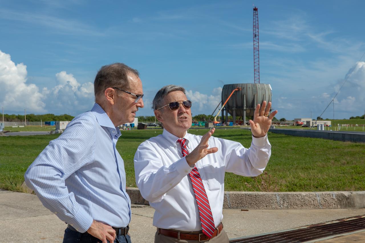
Kennedy Space Center Director Bob Cabana, at right, speaks to a member of the NASA Advisory Council at Launch Complex 39B during a tour of the multi-user spaceport on Oct. 30, 2019. In view behind them is the build-up of a new liquid hydrogen storage tank that will support Artemis launches to the Moon and on to Mars. The NASA Advisory Council provides the NASA administrator with counsel and advice on programs and issues of importance to the agency. Committee members conduct fact-finding sessions throughout the year in an effort to gain a broad understanding of current NASA issues and future mission implementation plans.

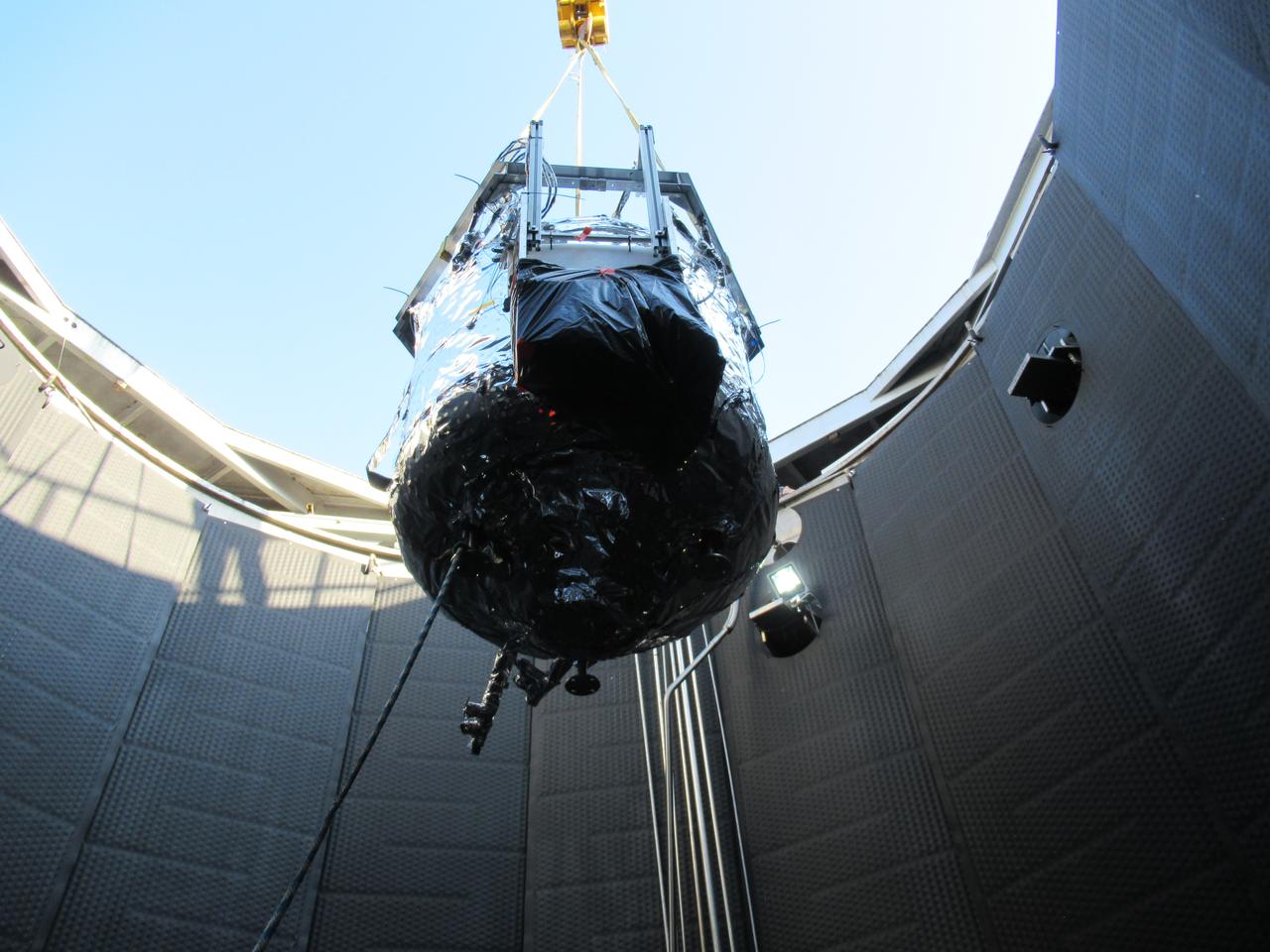
These photos show how teams at NASA’s Marshall Space Flight Center in Huntsville, Alabama, are testing an innovative approach to achieve zero boiloff storage of liquid hydrogen using two stages of active cooling, which could prevent the loss of valuable propellant during future long-duration spaceflight missions. Test teams installed the propellant tank in Test Stand 300 at NASA Marshall in early June, and the 90-day test campaign is scheduled to conclude in September. The tank is wrapped in a multi-layer insulation blanket that includes a thin aluminum heat shield fitted between layers. A second set of tubes, carrying helium at about minus 298 Fahrenheit, is integrated into the shield. This intermediate cooling layer intercepts and rejects incoming heat before it reaching the tank, easing the heat load on the tube-on-tank system. The Cryogenic Fluid Management Portfolio Project is a cross-agency team based at NASA Marshall and the agency’s Glenn Research Center in Cleveland. The cryogenic portfolio’s work is under NASA’s Technology Demonstration Missions Program, part of NASA’s Space Technology Mission Directorate, and is comprised of more than 20 individual technology development activities. For more information, contact NASA Marshall’s Office of Communications at 256-544-0034.
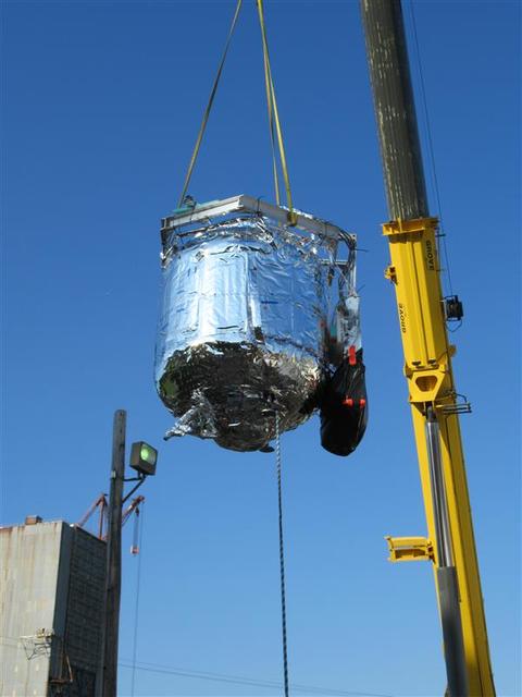
These photos show how teams at NASA’s Marshall Space Flight Center in Huntsville, Alabama, are testing an innovative approach to achieve zero boiloff storage of liquid hydrogen using two stages of active cooling, which could prevent the loss of valuable propellant during future long-duration spaceflight missions. Test teams installed the propellant tank in Test Stand 300 at NASA Marshall in early June, and the 90-day test campaign is scheduled to conclude in September. The tank is wrapped in a multi-layer insulation blanket that includes a thin aluminum heat shield fitted between layers. A second set of tubes, carrying helium at about minus 298 Fahrenheit, is integrated into the shield. This intermediate cooling layer intercepts and rejects incoming heat before it reaching the tank, easing the heat load on the tube-on-tank system. The Cryogenic Fluid Management Portfolio Project is a cross-agency team based at NASA Marshall and the agency’s Glenn Research Center in Cleveland. The cryogenic portfolio’s work is under NASA’s Technology Demonstration Missions Program, part of NASA’s Space Technology Mission Directorate, and is comprised of more than 20 individual technology development activities. For more information, contact NASA Marshall’s Office of Communications at 256-544-0034.
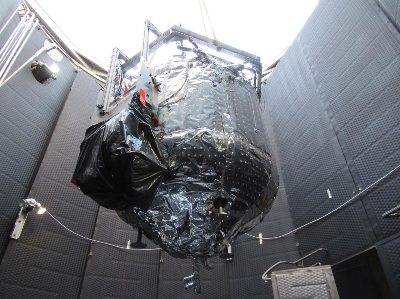
These photos show how teams at NASA’s Marshall Space Flight Center in Huntsville, Alabama, are testing an innovative approach to achieve zero boiloff storage of liquid hydrogen using two stages of active cooling, which could prevent the loss of valuable propellant during future long-duration spaceflight missions. Test teams installed the propellant tank in Test Stand 300 at NASA Marshall in early June, and the 90-day test campaign is scheduled to conclude in September. The tank is wrapped in a multi-layer insulation blanket that includes a thin aluminum heat shield fitted between layers. A second set of tubes, carrying helium at about minus 298 Fahrenheit, is integrated into the shield. This intermediate cooling layer intercepts and rejects incoming heat before it reaching the tank, easing the heat load on the tube-on-tank system. The Cryogenic Fluid Management Portfolio Project is a cross-agency team based at NASA Marshall and the agency’s Glenn Research Center in Cleveland. The cryogenic portfolio’s work is under NASA’s Technology Demonstration Missions Program, part of NASA’s Space Technology Mission Directorate, and is comprised of more than 20 individual technology development activities. For more information, contact NASA Marshall’s Office of Communications at 256-544-0034.

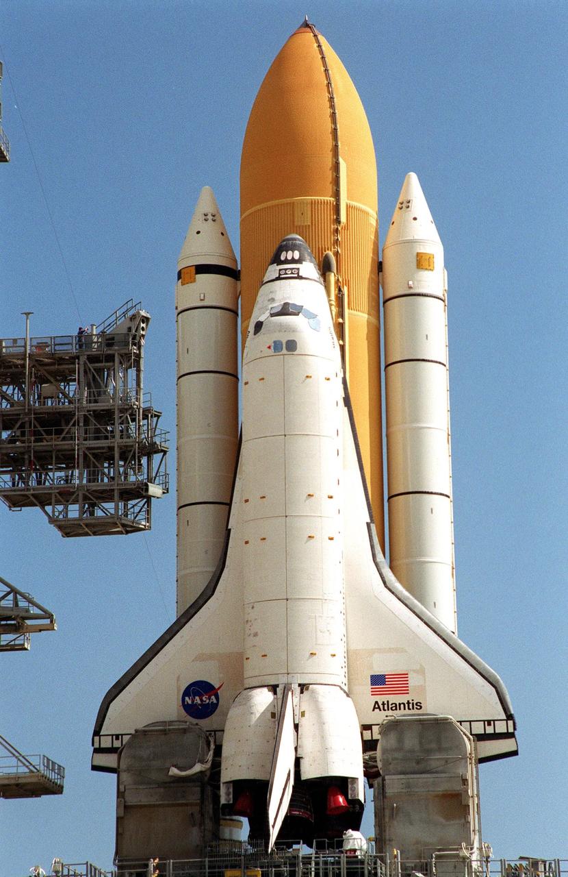
KENNEDY SPACE CENTER, FLA. -- Space Shuttle Atlantis, mounted on a mobile launch platform, finally rests on the hard stand of Launch Pad 39A after an early morning rollout. This is the second rollout for the shuttle. Seen on either side of the main engine exhaust hole on the launcher platform are the tail service masts. Their function is to provide umbilical connections for liquid oxygen and liquid hydrogen lines to fuel the external tank from storage tanks adjacent to the launch pad. Other umbilical lines carry helium and nitrogen, as well as ground electrical power and connections for vehicle data and communications. First motion out of the Vehicle Assembly Building was at 5:02 a.m. EDT. In late February, while Atlantis was on the launch pad, Atlantis' external tank received hail damage during a severe thunderstorm that passed through the Kennedy Space Center Launch Complex 39 area. The hail caused visible divots in the giant tank's foam insulation, as well as minor surface damage to about 26 heat shield tiles on the shuttle's left wing. The shuttle was returned to the VAB for repairs. The launch of Space Shuttle Atlantis on mission STS-117 is now targeted for June 8. A flight readiness review will be held on May 30 and 31. Photo credit: NASA/Troy Cryder
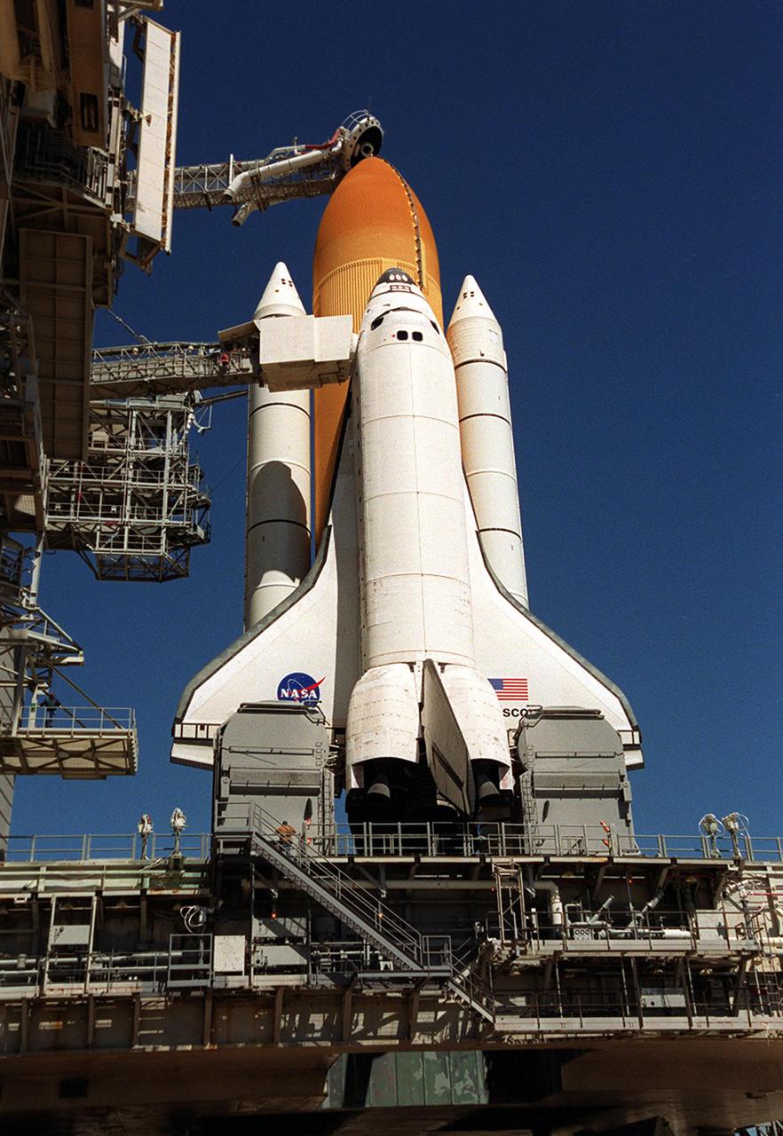
KENNEDY SPACE CENTER, Fla. -- Atop the mobile launcher platform, Space Shuttle Atlantis, with its orange external tank and white solid rocket boosters, sits on Launch Pad 39B after rollout from the Vehicle Assembly Building. Seen on either side of the orbiter’s tail are the tail service masts. They support the fluid, gas and electrical requirements of the orbiter’s liquid oxygen and liquid hydrogen aft umbilicals. The Shuttle is targeted for launch no earlier than July 12 on mission STS-104, the 10th flight to the International Space Station. The payload on the 11-day mission is the Joint Airlock Module, which will allow astronauts and cosmonauts in residence on the Station to perform future spacewalks without the presence of a Space Shuttle. The module, which comprises a crew lock and an equipment lock, will be connected to the starboard (right) side of Node 1 Unity. Atlantis will also carry oxygen and nitrogen storage tanks, vital to operation of the Joint Airlock, on a Spacelab Logistics Double Pallet in the payload bay. The tanks, to be installed on the perimeter of the Joint Module during the mission’s spacewalks, will support future spacewalk operations and experiments plus augment the resupply system for the Station’s Service Module
KENNEDY SPACE CENTER, Fla. -- Space Shuttle Discovery shines on Launch Pad 39B after rollback of the Rotating Service Structure. Situated above the external tank is the Gaseous Oxygen Vent Arm with the “beanie cap,” a vent hood. Extended out from the Fixed Service Structure (left) to the orbiter is the orbiter access arm with an environmentally controlled chamber, known as the White Room, at the end of the arm. The White Room provides entrance for the astronaut crew into the orbiter. On either side of the tail and main engines are the tail service masts. Rising 31 feet above the Mobile Launcher Platform, the tail masts provide umbilical connections for liquid oxygen and liquid hydrogen lines to fuel the external tank from storage tanks adjacent to the launch pad. Discovery carries the Multi-Purpose Logistics Module Leonardo, the primary delivery system used to resupply and return Station cargo requiring a pressurized environment. Leonardo will deliver up to 10 tons of laboratory racks filled with equipment, experiments and supplies for outfitting the newly installed U.S. Laboratory Destiny. Launch on mission STS-102 is scheduled March 8 at 6:42 a.m. EST

KENNEDY SPACE CENTER, Fla. -- Space Shuttle Discovery shines on Launch Pad 39B after rollback of the Rotating Service Structure. Situated above the external tank is the Gaseous Oxygen Vent Arm with the “beanie cap,” a vent hood. Extended out from the Fixed Service Structure (left) to the orbiter is the orbiter access arm with an environmentally controlled chamber, known as the White Room, at the end of the arm. The White Room provides entrance for the astronaut crew into the orbiter. On either side of the tail and main engines are the tail service masts. Rising 31 feet above the Mobile Launcher Platform, the tail masts provide umbilical connections for liquid oxygen and liquid hydrogen lines to fuel the external tank from storage tanks adjacent to the launch pad. Discovery carries the Multi-Purpose Logistics Module Leonardo, the primary delivery system used to resupply and return Station cargo requiring a pressurized environment. Leonardo will deliver up to 10 tons of laboratory racks filled with equipment, experiments and supplies for outfitting the newly installed U.S. Laboratory Destiny. Launch on mission STS-102 is scheduled March 8 at 6:42 a.m. EST
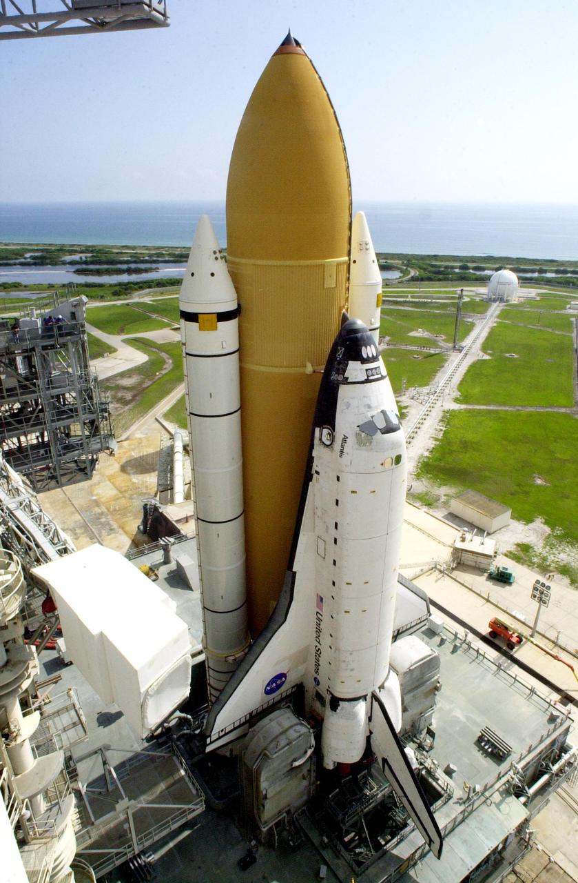
KENNEDY SPACE CENTER, Fla. -- Atop the mobile launcher platform, Space Shuttle Atlantis sits on Launch Pad 39B after rollout from the Vehicle Assembly Building. Seen on either side of the orbiter’s tail are the tail service masts. They support the fluid, gas and electrical requirements of the orbiter’s liquid oxygen and liquid hydrogen aft umbilicals. To the left of the orbiter is the white environmental chamber (white room) that mates with the orbiter and holds six persons. It provides access to the orbiter crew compartment. In the background is the Atlantic Ocean. The Shuttle is targeted for launch no earlier than July 12 on mission STS-104, the 10th flight to the International Space Station. The payload on the 11-day mission is the Joint Airlock Module, which will allow astronauts and cosmonauts in residence on the Station to perform future spacewalks without the presence of a Space Shuttle. The module, which comprises a crew lock and an equipment lock, will be connected to the starboard (right) side of Node 1 Unity. Atlantis will also carry oxygen and nitrogen storage tanks, vital to operation of the Joint Airlock, on a Spacelab Logistics Double Pallet in the payload bay. The tanks, to be installed on the perimeter of the Joint Module during the mission’s spacewalks, will support future spacewalk operations and experiments plus augment the resupply system for the Station’s Service Module
KENNEDY SPACE CENTER, Fla. -- Atop the mobile launcher platform, Space Shuttle Atlantis sits on Launch Pad 39B after rollout from the Vehicle Assembly Building. Seen on either side of the orbiter’s tail are the tail service masts. They support the fluid, gas and electrical requirements of the orbiter’s liquid oxygen and liquid hydrogen aft umbilicals. To the left of the orbiter is the white environmental chamber (white room) that mates with the orbiter and holds six persons. It provides access to the orbiter crew compartment. In the background is the Atlantic Ocean. The Shuttle is targeted for launch no earlier than July 12 on mission STS-104, the 10th flight to the International Space Station. The payload on the 11-day mission is the Joint Airlock Module, which will allow astronauts and cosmonauts in residence on the Station to perform future spacewalks without the presence of a Space Shuttle. The module, which comprises a crew lock and an equipment lock, will be connected to the starboard (right) side of Node 1 Unity. Atlantis will also carry oxygen and nitrogen storage tanks, vital to operation of the Joint Airlock, on a Spacelab Logistics Double Pallet in the payload bay. The tanks, to be installed on the perimeter of the Joint Module during the mission’s spacewalks, will support future spacewalk operations and experiments plus augment the resupply system for the Station’s Service Module
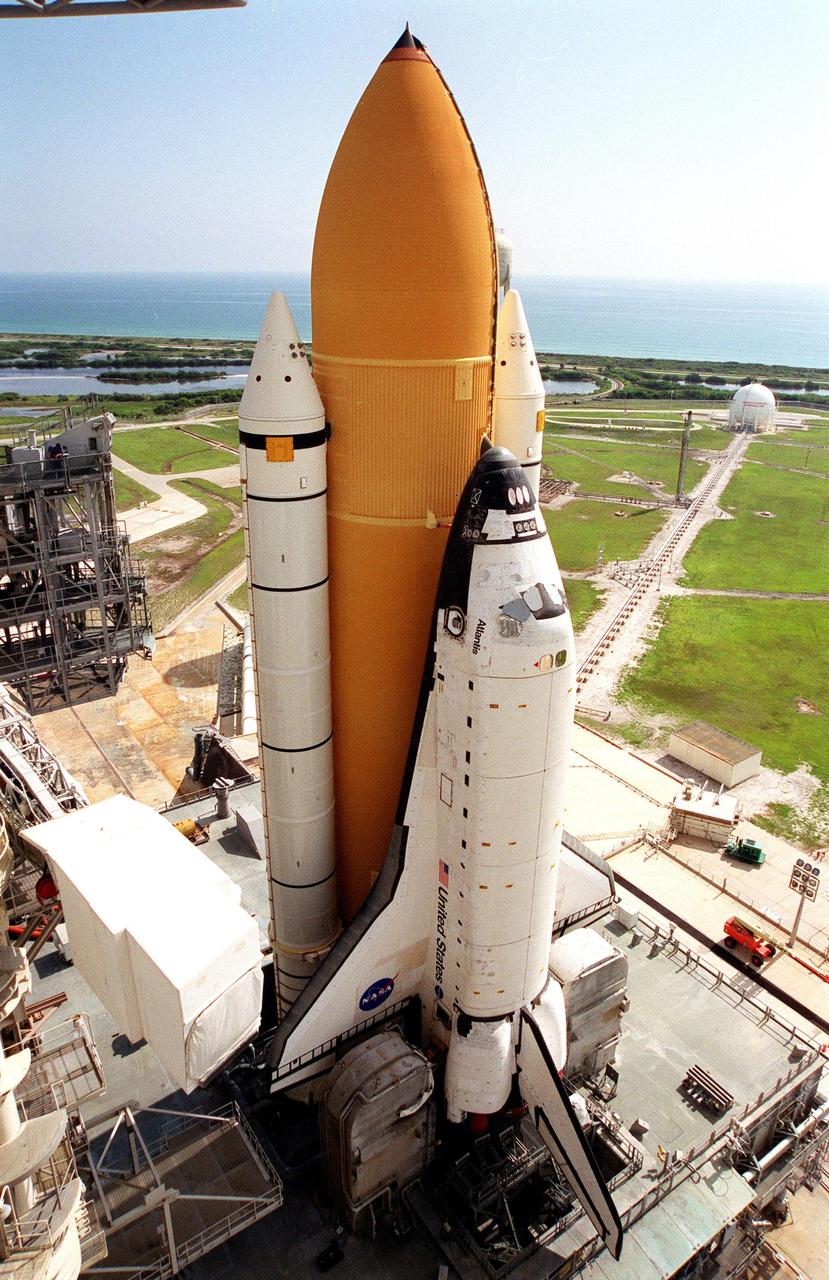
KENNEDY SPACE CENTER, Fla. -- Atop the mobile launcher platform, Space Shuttle Atlantis arrives on Launch Pad 39B after rollout from the Vehicle Assembly Building. Seen on either side of the orbiter’s tail are the tail service masts. They support the fluid, gas and electrical requirements of the orbiter’s liquid oxygen and liquid hydrogen aft umbilicals. The Shuttle is targeted for launch no earlier than July 12 on mission STS-104, the 10th flight to the International Space Station. The payload on the 11-day mission is the Joint Airlock Module, which will allow astronauts and cosmonauts in residence on the Station to perform future spacewalks without the presence of a Space Shuttle. The module, which comprises a crew lock and an equipment lock, will be connected to the starboard (right) side of Node 1 Unity. Atlantis will also carry oxygen and nitrogen storage tanks, vital to operation of the Joint Airlock, on a Spacelab Logistics Double Pallet in the payload bay. The tanks, to be installed on the perimeter of the Joint Module during the mission’s spacewalks, will support future spacewalk operations and experiments plus augment the resupply system for the Station’s Service Module
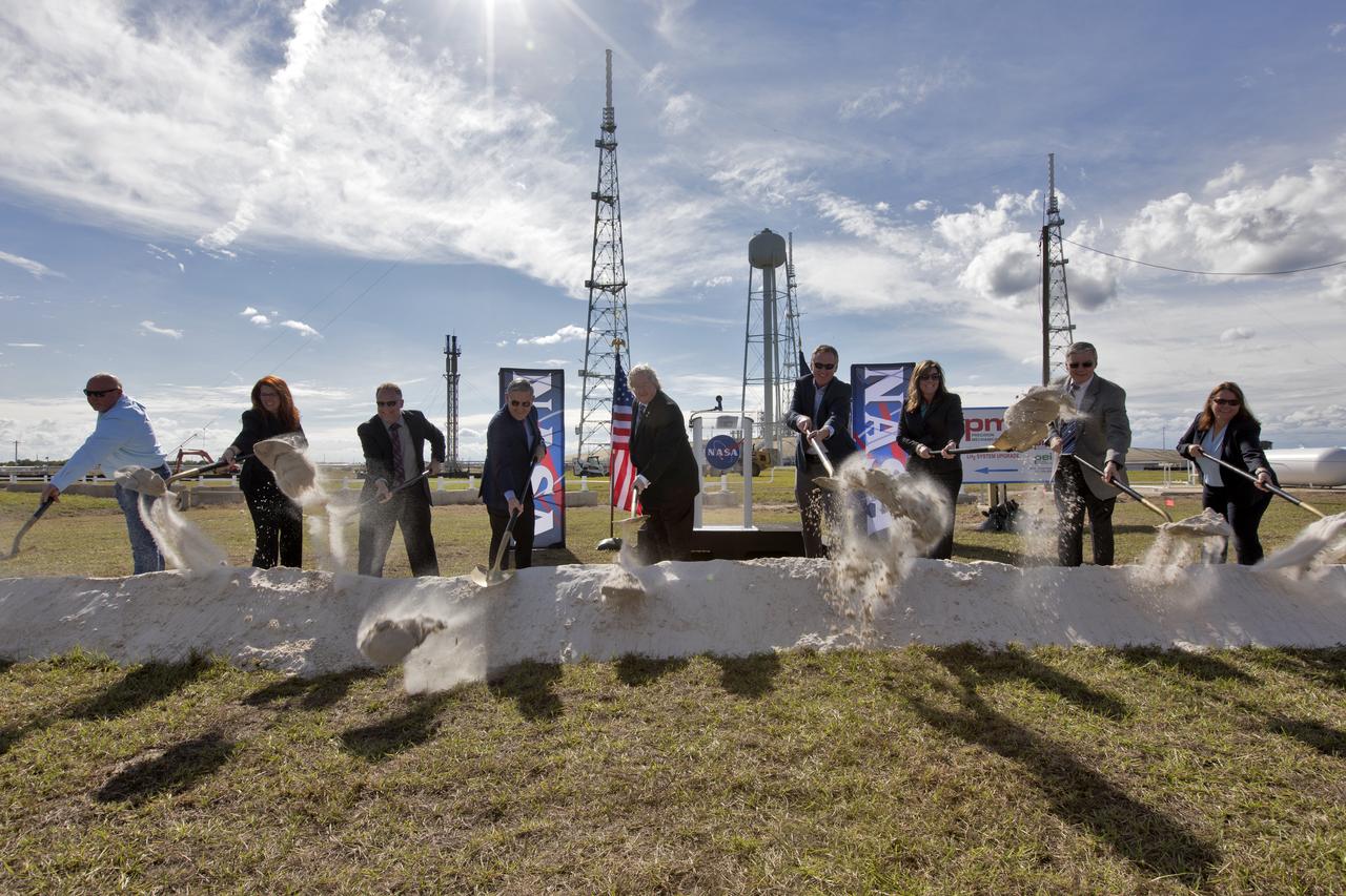
On Dec. 19, 2018, at NASA Kennedy Space Center's Launch Complex 39B, agency and contractor managers break ground for a new liquid hydrogen tank. Participating, from the left, are Todd Gray, president of Precision Mechanical, prime contractor for the project; Charlie Blackwell-Thompson, launch director; Shawn Quinn, director of Engineering; Bob Cabana, center director; Bill Hill, deputy associate administrator for Exploration Systems Development at NASA Headquarters in Washington; Mike Bolger, program manager for Exploration Ground Systems (EGS); Jennifer Kunz, deputy program manager for EGS, Andy Allen, general manager for Jacobs, NASA's Test and Operations Support Contractor; and Regina Spellman, launch pad senior project manager in EGS. The storage facility will hold 1.25 million gallons of the propellant for NASA's Space Launch System rocket designed to boost the agency's Orion spacecraft, sending humans to distant destinations such as the Moon and Mars.
At sunrise on Oct. 30, 2020, the mobile launcher for the Artemis I mission, atop crawler-transporter 2, moves slowly down the ramp at Launch Pad 39B to return to the Vehicle Assembly Building at NASA’s Kennedy Space Center in Florida. In view in the foreground is the liquid hydrogen storage tank. The nearly 400-foot-tall mobile launcher was at the pad for 10 days, while engineers with Exploration Ground Systems and Jacobs performed several tasks, including a timing test to validate the launch team’s countdown timeline, and a thorough, top-to-bottom wash down of the mobile launcher to remove any debris remaining from construction and installation of the umbilical arms. Artemis I will test the Orion spacecraft and Space Launch System as an integrated system ahead of crewed flights to the Moon. Under the Artemis program, NASA will land the first woman and the next man on the Moon in 2024.
These photos show how teams at NASA’s Marshall Space Flight Center in Huntsville, Alabama, are testing an innovative approach to achieve zero boiloff storage of liquid hydrogen using two stages of active cooling, which could prevent the loss of valuable propellant during future long-duration spaceflight missions. Test teams installed the propellant tank in Test Stand 300 at NASA Marshall in early June, and the 90-day test campaign is scheduled to conclude in September. The tank is wrapped in a multi-layer insulation blanket that includes a thin aluminum heat shield fitted between layers. A second set of tubes, carrying helium at about minus 298 Fahrenheit, is integrated into the shield. This intermediate cooling layer intercepts and rejects incoming heat before it reaching the tank, easing the heat load on the tube-on-tank system. The Cryogenic Fluid Management Portfolio Project is a cross-agency team based at NASA Marshall and the agency’s Glenn Research Center in Cleveland. The cryogenic portfolio’s work is under NASA’s Technology Demonstration Missions Program, part of NASA’s Space Technology Mission Directorate, and is comprised of more than 20 individual technology development activities. For more information, contact NASA Marshall’s Office of Communications at 256-544-0034.
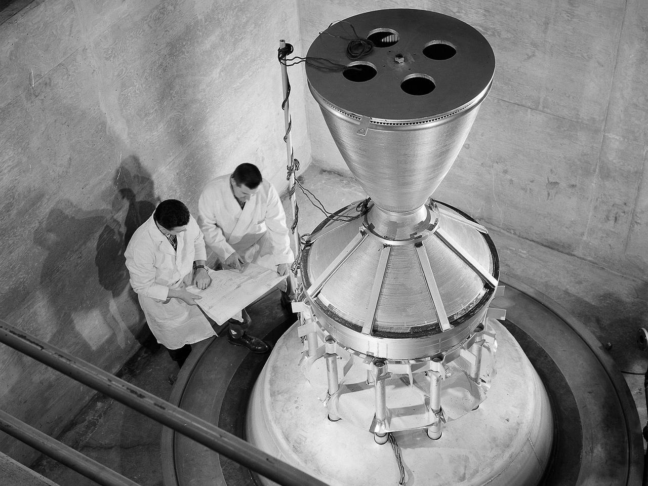
Technicians manufacture a nozzle for the Kiwi B-1-B nuclear rocket engine in the Fabrication Shop’s vacuum oven at the National Aeronautics and Space Administration (NASA) Lewis Research Center. The Nuclear Engine for Rocket Vehicle Applications (NERVA) was a joint NASA and Atomic Energy Commission (AEC) endeavor to develop a nuclear-powered rocket for both long-range missions to Mars and as a possible upper-stage for the Apollo Program. The early portion of the program consisted of basic reactor and fuel system research. This was followed by a series of Kiwi reactors built to test basic nuclear rocket principles in a non-flying nuclear engine. The next phase, NERVA, would create an entire flyable engine. The final phase of the program, called Reactor-In-Flight-Test, would be an actual launch test. The AEC was responsible for designing the nuclear reactor and overall engine. NASA Lewis was responsible for developing the liquid-hydrogen fuel system. The turbopump, which pumped the fuels from the storage tanks to the engine, was the primary tool for restarting the engine. The NERVA had to be able to restart in space on its own using a safe preprogrammed startup system. Lewis researchers endeavored to design and test this system. This non-nuclear Kiwi engine, seen here, was being prepared for tests at Lewis’ High Energy Rocket Engine Research Facility (B-1) located at Plum Brook Station. The tests were designed to start an unfueled Kiwi B-1-B reactor and its Aerojet Mark IX turbopump without any external power.