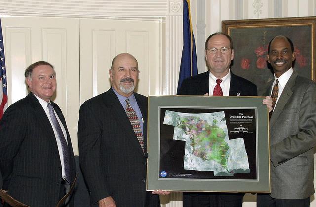
NASA Stennis Space Center (SSC) Interim Center Director Michael Rudolphi (second from right) presents Louisiana Gov. Mike Foster (second from left) an image from space of the area that comprised the Louisiana Purchase. Gov. Foster and Rudolphi signed a Memorandum of Understanding (MOU) between SSC and the state of Louisiana to promote technology transfer partnerships. Also pictured are Charles D'Agostino (left), executive director of the Louisiana Business and Technology Center, and Don Hutchison, secretary of the Louisiana Department of Economic Development.
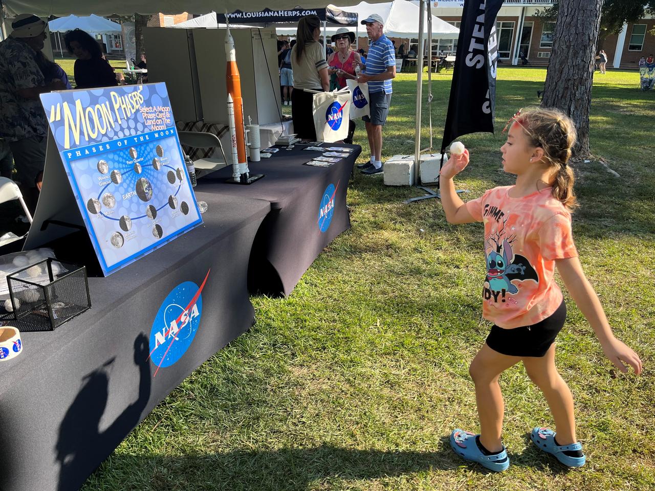
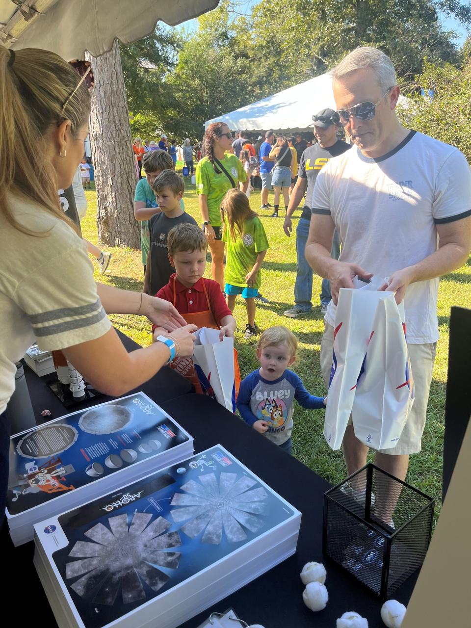
NASA Stennis representatives inspire the Artemis Generation Oct. 12 at the Wild Things event celebrating National Wildlife Refuge Week in Lacombe, Louisiana. Participants played a game to identify different phases of the Moon and learned more about NASA’s return to the Moon. The event was hosted by Friends of Louisiana Wildlife Refuges, Inc. and Southeast Louisiana National Wildlife Refuges Complex at Bayou Lacombe Center, headquarters for the nine National Wildlife Refuges in southeast Louisiana.
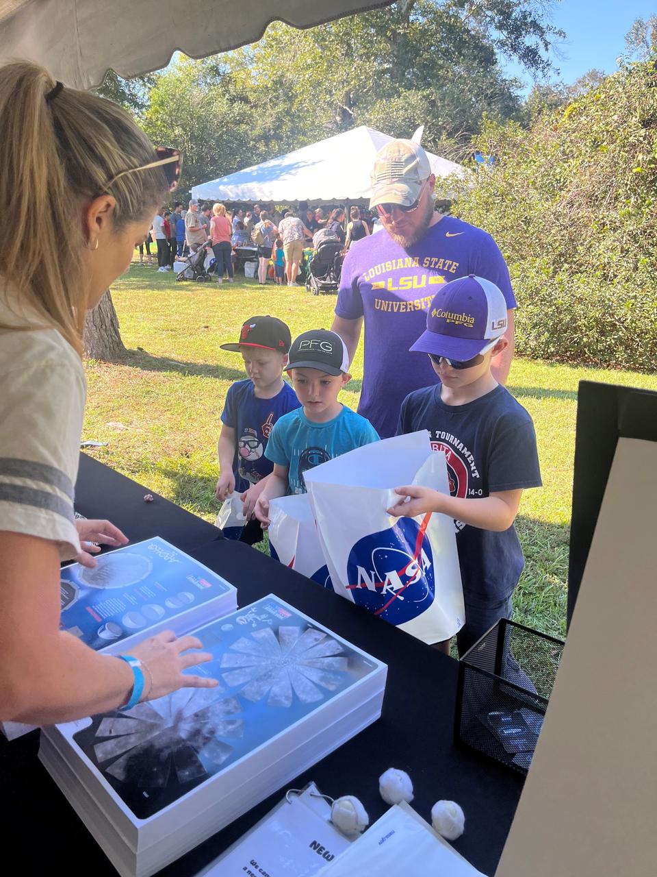
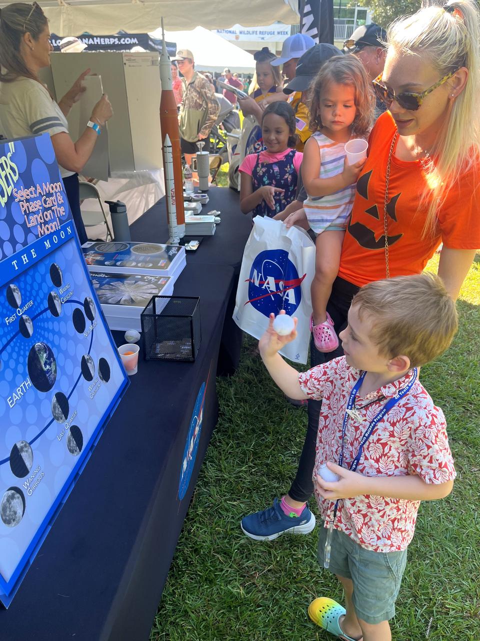
NASA Stennis representatives inspire the Artemis Generation Oct. 12 at the Wild Things event celebrating National Wildlife Refuge Week in Lacombe, Louisiana. Participants played a game to identify different phases of the Moon and learned more about NASA’s return to the Moon. The event was hosted by Friends of Louisiana Wildlife Refuges, Inc. and Southeast Louisiana National Wildlife Refuges Complex at Bayou Lacombe Center, headquarters for the nine National Wildlife Refuges in southeast Louisiana.
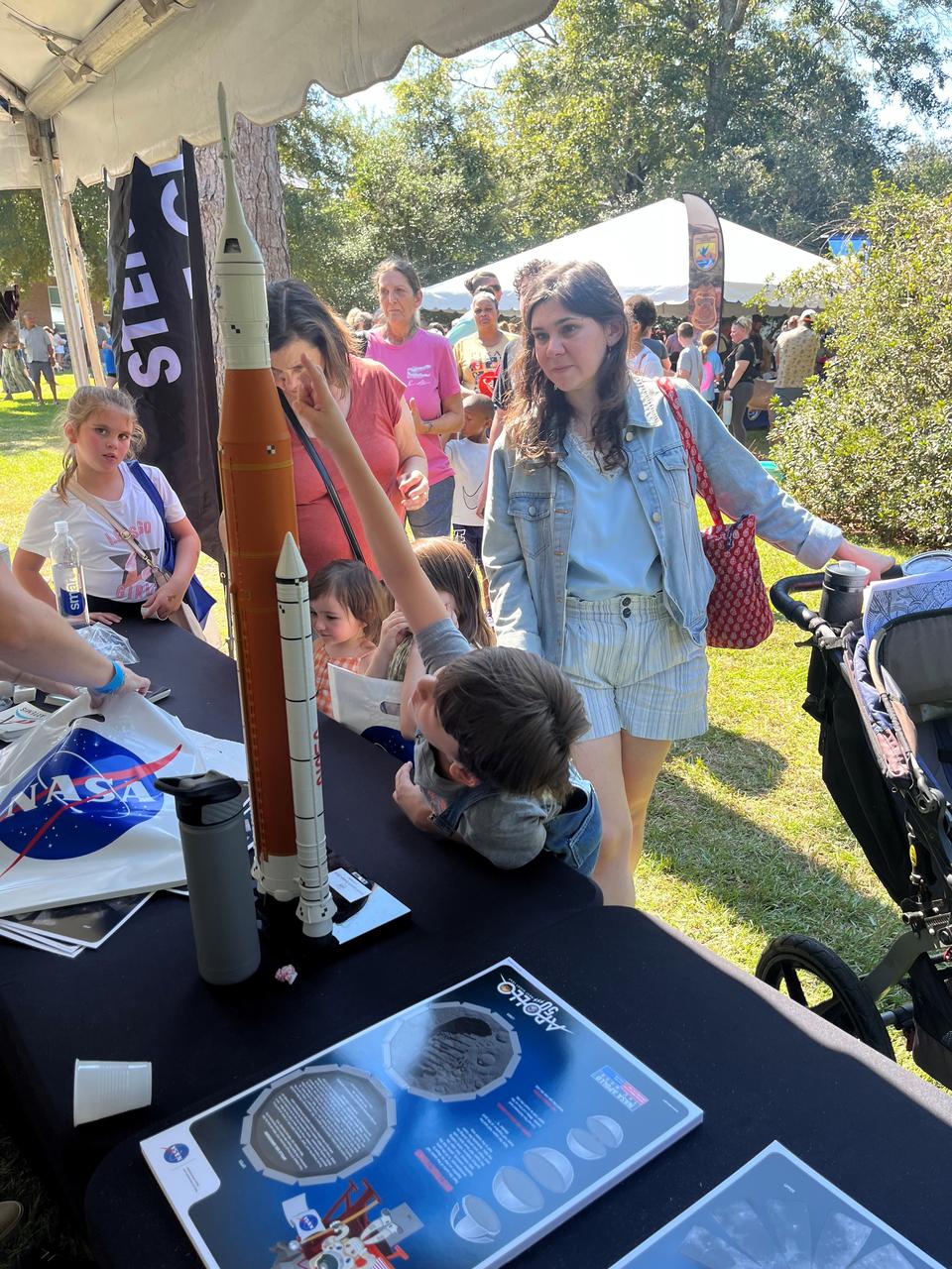
NASA Stennis representatives inspire the Artemis Generation Oct. 12 at the Wild Things event celebrating National Wildlife Refuge Week in Lacombe, Louisiana. Participants played a game to identify different phases of the Moon and learned more about NASA’s return to the Moon. The event was hosted by Friends of Louisiana Wildlife Refuges, Inc. and Southeast Louisiana National Wildlife Refuges Complex at Bayou Lacombe Center, headquarters for the nine National Wildlife Refuges in southeast Louisiana.

NASA Stennis representatives inspire the Artemis Generation Oct. 12 at the Wild Things event celebrating National Wildlife Refuge Week in Lacombe, Louisiana. Participants played a game to identify different phases of the Moon and learned more about NASA’s return to the Moon. The event was hosted by Friends of Louisiana Wildlife Refuges, Inc. and Southeast Louisiana National Wildlife Refuges Complex at Bayou Lacombe Center, headquarters for the nine National Wildlife Refuges in southeast Louisiana.
NASA Stennis representatives inspire the Artemis Generation Oct. 12 at the Wild Things event celebrating National Wildlife Refuge Week in Lacombe, Louisiana. Participants played a game to identify different phases of the Moon and learned more about NASA’s return to the Moon. The event was hosted by Friends of Louisiana Wildlife Refuges, Inc. and Southeast Louisiana National Wildlife Refuges Complex at Bayou Lacombe Center, headquarters for the nine National Wildlife Refuges in southeast Louisiana.
NASA Stennis representatives inspire the Artemis Generation Oct. 12 at the Wild Things event celebrating National Wildlife Refuge Week in Lacombe, Louisiana. Participants played a game to identify different phases of the Moon and learned more about NASA’s return to the Moon. The event was hosted by Friends of Louisiana Wildlife Refuges, Inc. and Southeast Louisiana National Wildlife Refuges Complex at Bayou Lacombe Center, headquarters for the nine National Wildlife Refuges in southeast Louisiana.
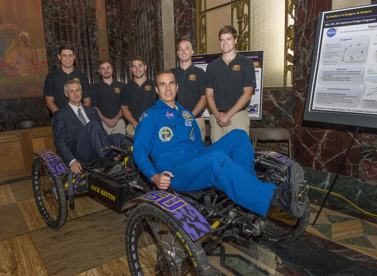
ASTRONAUT RICK MASTRACCHIO WITH LSU HUMAN EXPLORATION ROVER CHALLENGE TEAM (WINNER ROOKIE AWARD) IN ROTUNDA OF LOUISIANA STATE CAPITOL BUILDING
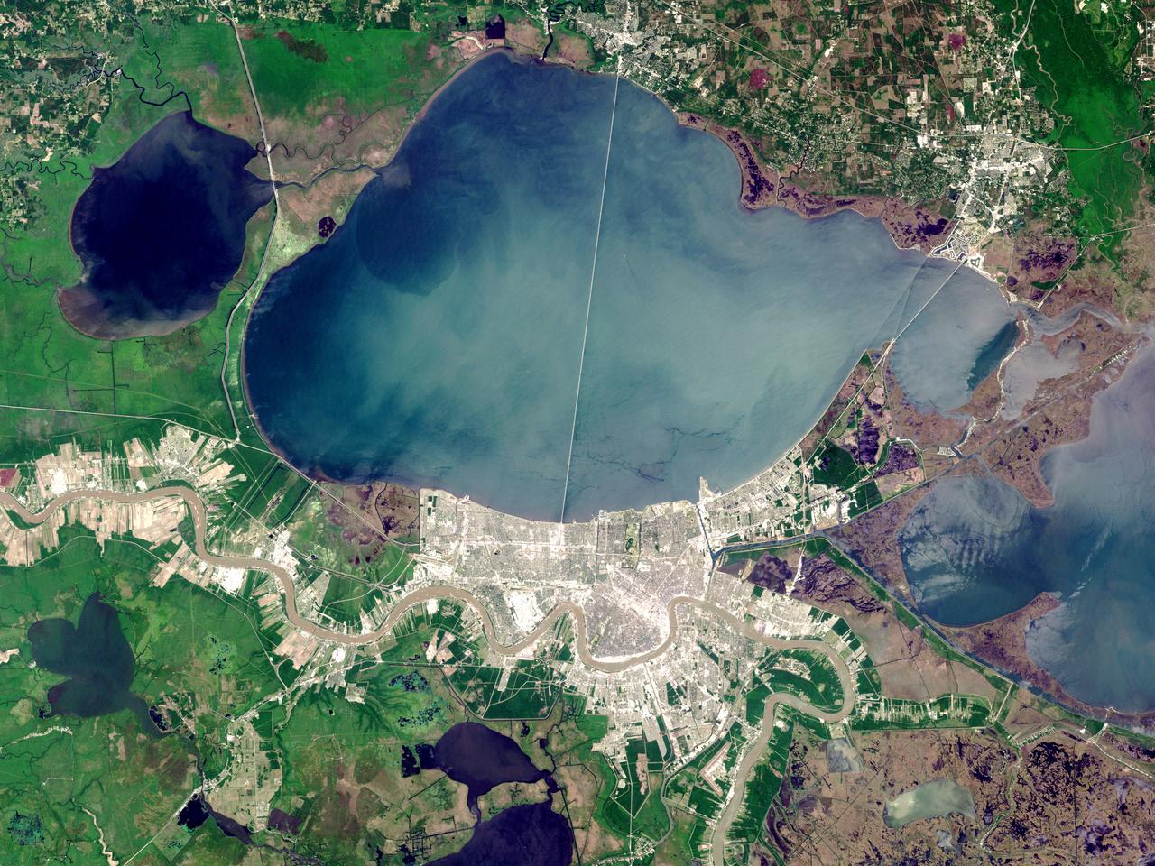
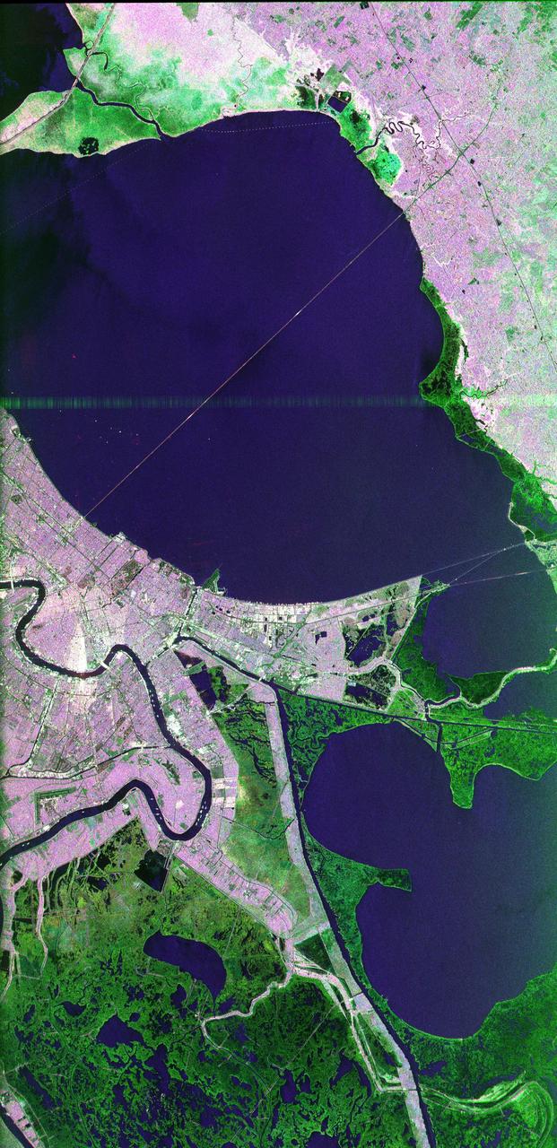
On Sunday, February 3, roughly 800 million eyes from all over the world focused on the Louisiana Superdome in New Orleans as the New England Patriots battled the St. Louis Rams for the NFL Championship in Super Bowl XXXVI. This true color image of New Orleans was acquired on April 26, 2000, by the Enhanced Thematic Mapper plus (ETM+), flying aboard the Landsat 7 satellite. Lake Pontchartrain borders the city to the north. The big river winding its way east to west through the image is the Mississippi. The Louisiana Superdome, built in 1975, sits just inside the rightmost portion of the big river bend that cradles downtown New Orleans. The city, however, may not be around to hold a Super Bowl in 2102. New Orleans is slowly sinking into the Gulf of Mexico. The construction of flood walls and dams north of New Orleans over the past century have prevented sediments carried by the Mississippi River from reaching New Orleans and the Mississippi River Delta. Before the dams were built, river sediments would empty out onto the delta adding layer upon layer of new soil each year. The additional soil prevented the Gulf from subsuming the delta. Unless drastic measures are taken, the city and the delta could be awash in seawater by the end of this century. Image by Robert Simmon, based on data provided by the Landsat 7 Science Team Credit: NASA/GSFC/Landsat <b><a href="http://www.nasa.gov/centers/goddard/home/index.html" rel="nofollow">NASA Goddard Space Flight Center</a></b> enables NASA’s mission through four scientific endeavors: Earth Science, Heliophysics, Solar System Exploration, and Astrophysics. Goddard plays a leading role in NASA’s accomplishments by contributing compelling scientific knowledge to advance the Agency’s mission. <b>Follow us on <a href="http://twitter.com/NASA_GoddardPix" rel="nofollow">Twitter</a></b> <b>Join us on <a href="http://www.facebook.com/pages/Greenbelt-MD/NASA-Goddard/395013845897?ref=tsd" rel="nofollow">Facebook</a></b>
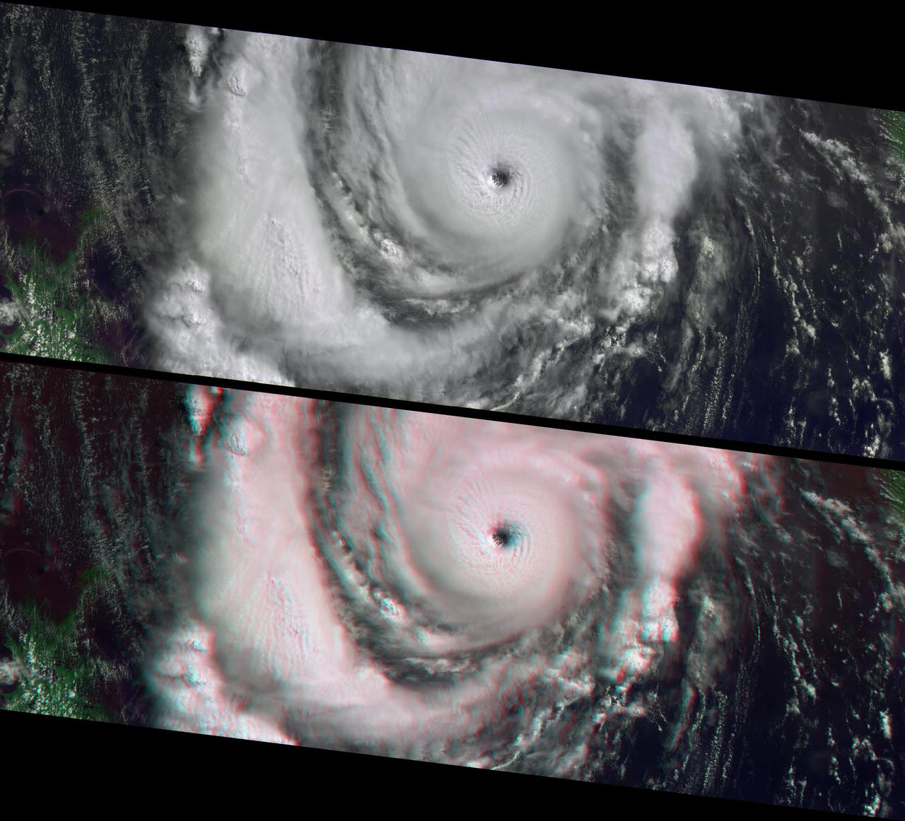
This anaglyph from the MISR instrument aboard NASA Terra spacecraft shows Hurricane Lili headed for Louisiana on October 2, 2002. 3D glasses are necessary to view this image.
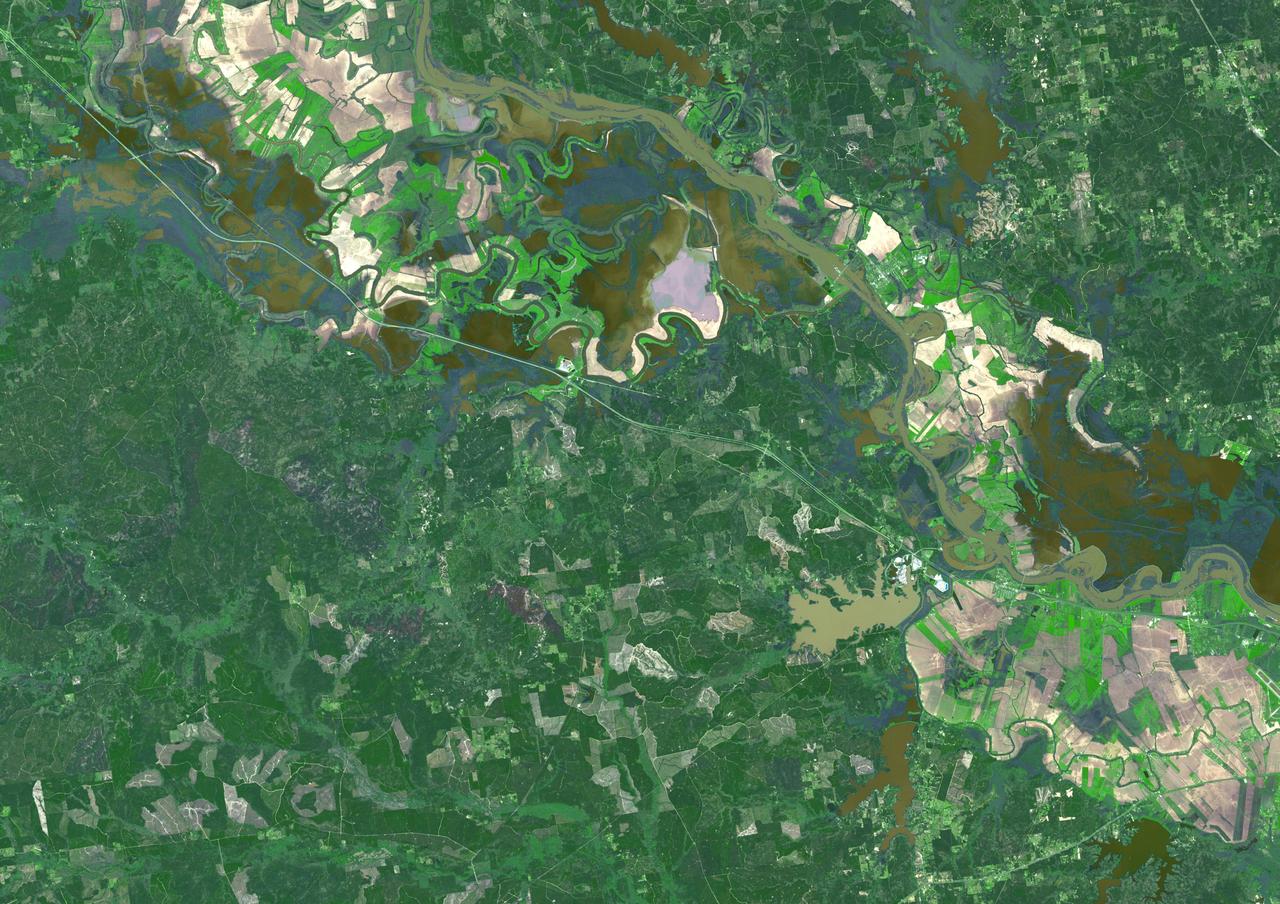
Torrential rains in the mid-South of the United States in mid-March 2016 produced flooding throughout Texas, Louisiana and Mississippi. On March 21, 2016, the Advanced Spaceborne Thermal Emission and Reflection Radiometer (ASTER) instrument on NASA's Terra spacecraft acquired this image showing persistent flooding along the Mississippi River between the Louisiana cities of Alexandria and Natchitoches. The image covers an area of 25 to 36 miles (41 by 58 kilometers), and is located at 31.5 degrees north, 92.8 degrees west. http://photojournal.jpl.nasa.gov/catalog/PIA20533

This image acquired on May 24, 2010 by NASA Terra spacecraft shows oil from the former Deepwater Horizon rig encroaching upon several of Louisiana wildlife habitats.
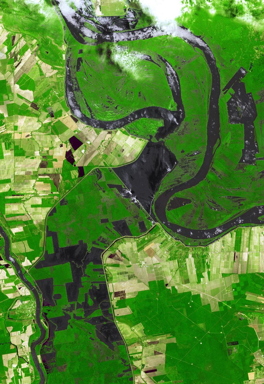
NASA Terra spacecraft shows the water flow after the U.S. Army Corps of Engineers opened the Morganza Spillway, a flood control structure along the western bank of the Mississippi River in Louisiana, to ease flooding along levee systems on May 14, 2011.

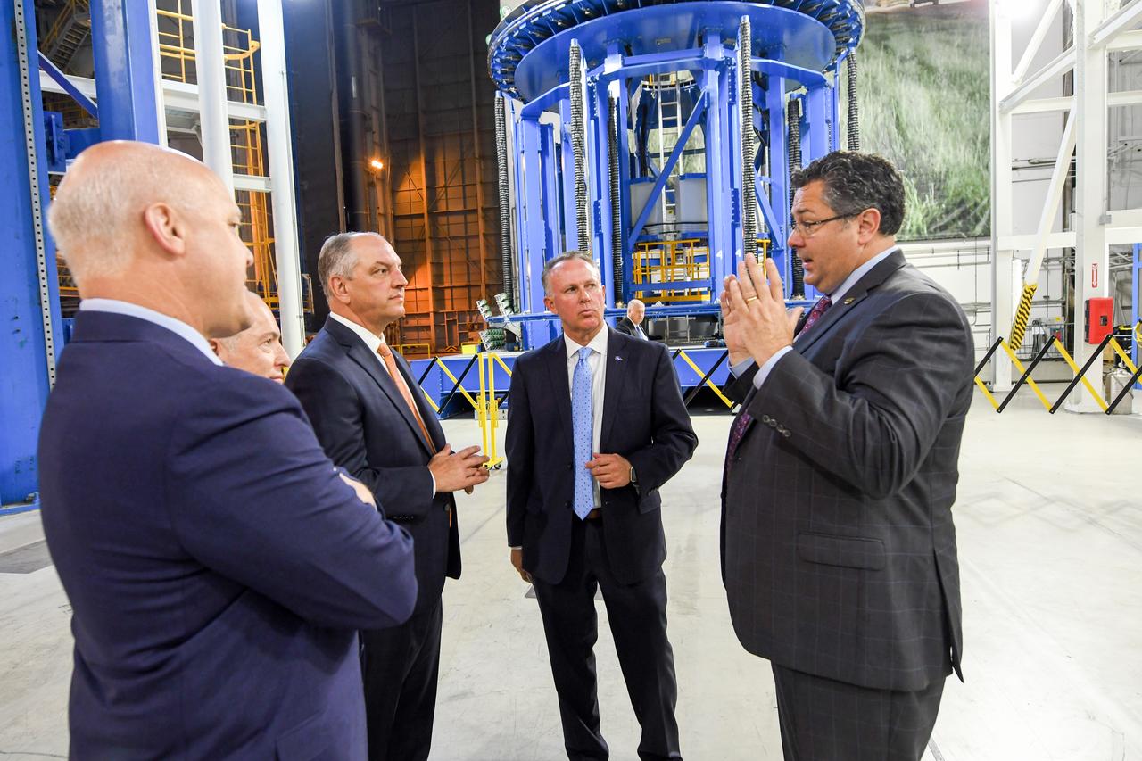
Louisiana Gov. John Bel Edwards visited NASA’s Michoud Assembly Facility in New Orleans and spoke about the state’s partnerships with NASA and the 20 companies and government agencies located at the facility. NASA is building its new deep space rocket, the Space Launch System, and the Orion spacecraft at Michoud.
NASA officials were joined by Louisiana Gov. John Bel Edwards and New Orleans Mayor Mitch Landrieu, who toured the Michoud Assembly Facility in New Orleans and got a first-hand look at NASA’s new deep space vehicles being built at the facility.
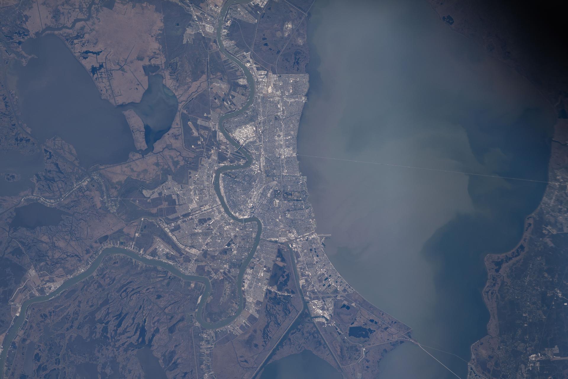
iss074e0150293 (Jan. 19, 2026) --- The Mississippi River winds through New Orleans, Louisiana, and its suburbs on the south shore of Lake Pontchartrain in this photograph taken from the International Space Station as it orbited 258 miles above Earth.

iss072e575684 (Jan. 24, 2025) --- New Orleans, Louisiana, and its suburbs along the Mississippi River and on the shoreline of Lake Pontchartrain are pictured from the International Space Station as it orbited above.
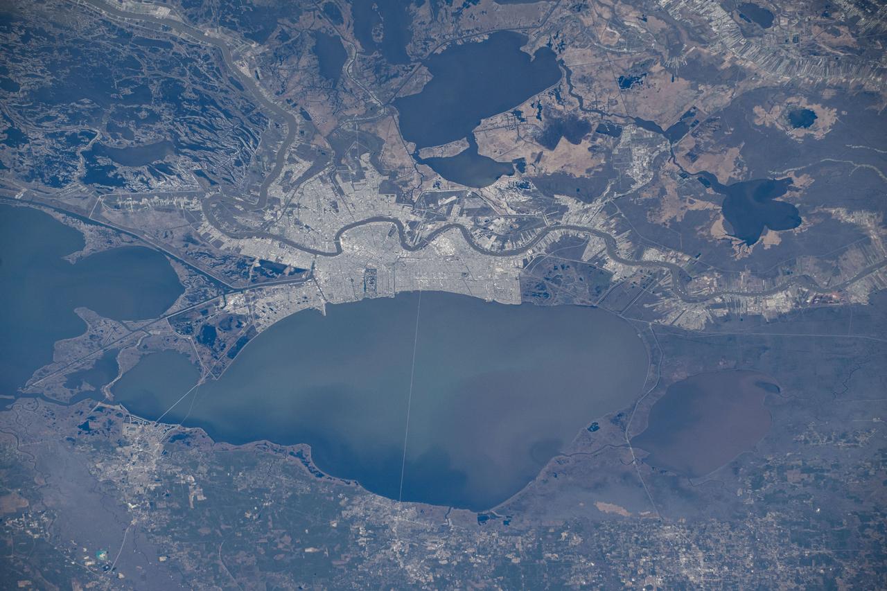
iss072e575658 (Jan. 24, 2025) --- New Orleans, Louisiana, and its suburbs along the Mississippi River and on the shoreline of Lake Pontchartrain are pictured from the International Space Station as it orbited above.
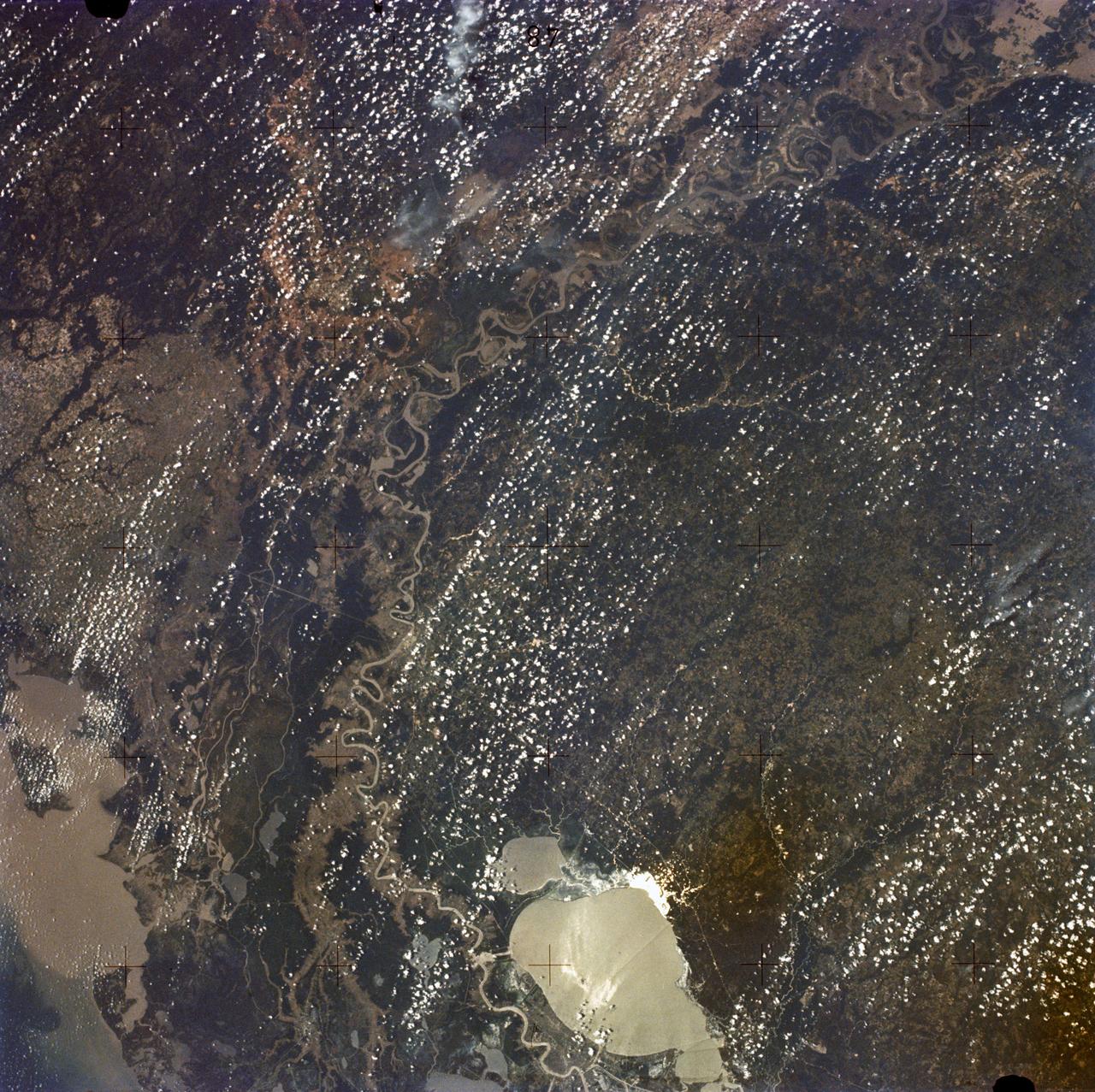
SL2-05-397 (22 June 1973) --- New Orleans, Louisiana, Mississippi River, and Lake Pontchartrain (31.0N, 91.0W) can all be seen in this single detailed view. The marshlands of the Atchafalaya Basin, previously the main drainage way for the Mississippi River, can be seen to be partially silted as a result of sediments. The long narrow field patterns fronting on the river is called the "Long Lot" system of equal land distribution based on the French Napoleonic Civil Code. Photo credit: NASA
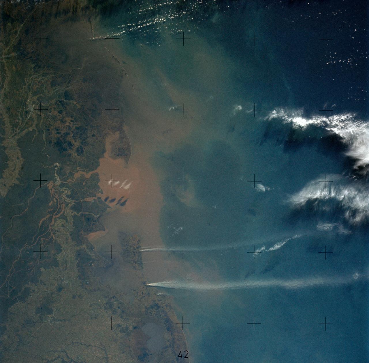
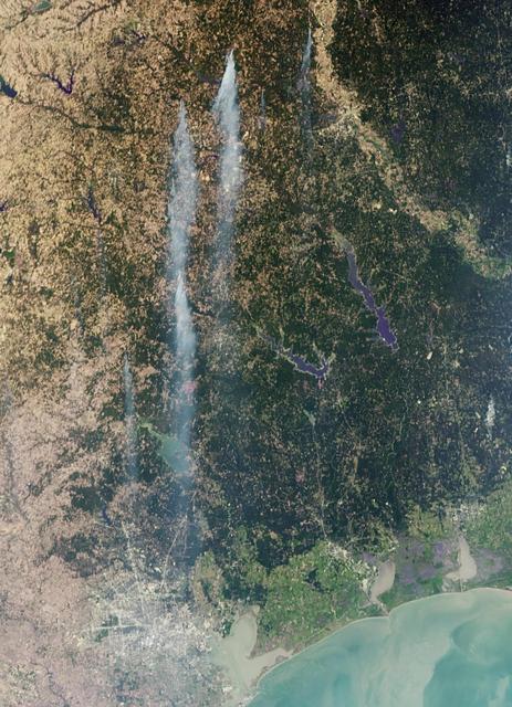
SL4-136-3475 (February 1974) --- A vertical view of the Gulf coast area of Louisiana (29.0N, 92.0W) as seen from the Skylab space station in Earth orbit. A Skylab 4 crewman used a hand-held 70mm Hasselblad camera to take this picture. This view extends from White Lake and Pecan Island (bottom border) eastward to the Mississippi River delta (top left). Atchafalaya Bay (red) is in the center. The Bayou Teche area is included in this view. A prominent feature of this photograph is two large white smoke plumes extending from Louisiana south into the Gulf of Mexico. The larger smoke plume originates on the southern shore of Vermillion Bay. The other plume extends from the southern shore of Marsh Island. The prononced narrow width and length of the plumes indicate that a strong offshore wind is present. Approximately 100 miles of the plumes are visible in this photograph; but they probably extend well into the Gulf of Mexico. Photo credit: NASA
This image of the area surrounding the city of New Orleans, Louisiana in the southeastern United States demonstrates the ability of multi-frequency imaging radar to distinguish different types of land cover. The dark area in the center is Lake Pontchartrain. The thin line running across the lake is a causeway connecting New Orleans to the city of Mandeville. Lake Borgne is the dark area in the lower right of the image. The Mississippi River appears as a dark, wavy line in the lower left. The white dots on the Mississippi are ships. The French Quarter is the brownish square near the left center of the image. Lakefront Airport, a field used mostly for general aviation, is the bright spot near the center, jutting out into Lake Pontchartrain. The image was acquired by the Spaceborne Imaging Radar C/X-Band Synthetic Aperture Radar (SIR-C/X-SAR) during orbit 39 of space shuttle Endeavour on October 2, 1994. The area is located at 30.10 degrees north latitude and 89.1 degrees west longitude. The area shown is approximately 100 kilometers (60 miles) by 50 kilometers (30 miles). The colors in this image were obtained using the following radar channels: red represents the L-band (horizontally transmitted and received); green represents the C-band (horizontally transmitted and received); blue represents the L-band (vertically transmitted and received). The green areas are primarily vegetation consisting of swamp land and swamp forest (bayou) growing on sandy soil, while the pink areas are associated with reflections from buildings in urban and suburban areas. Different tones and colors in the vegetation areas will be studied by scientists to see how effective imaging radar data is in discriminating between different types of wetlands. Accurate maps of coastal wetland areas are important to ecologists studying wild fowl and the coastal environment. http://photojournal.jpl.nasa.gov/catalog/PIA01300
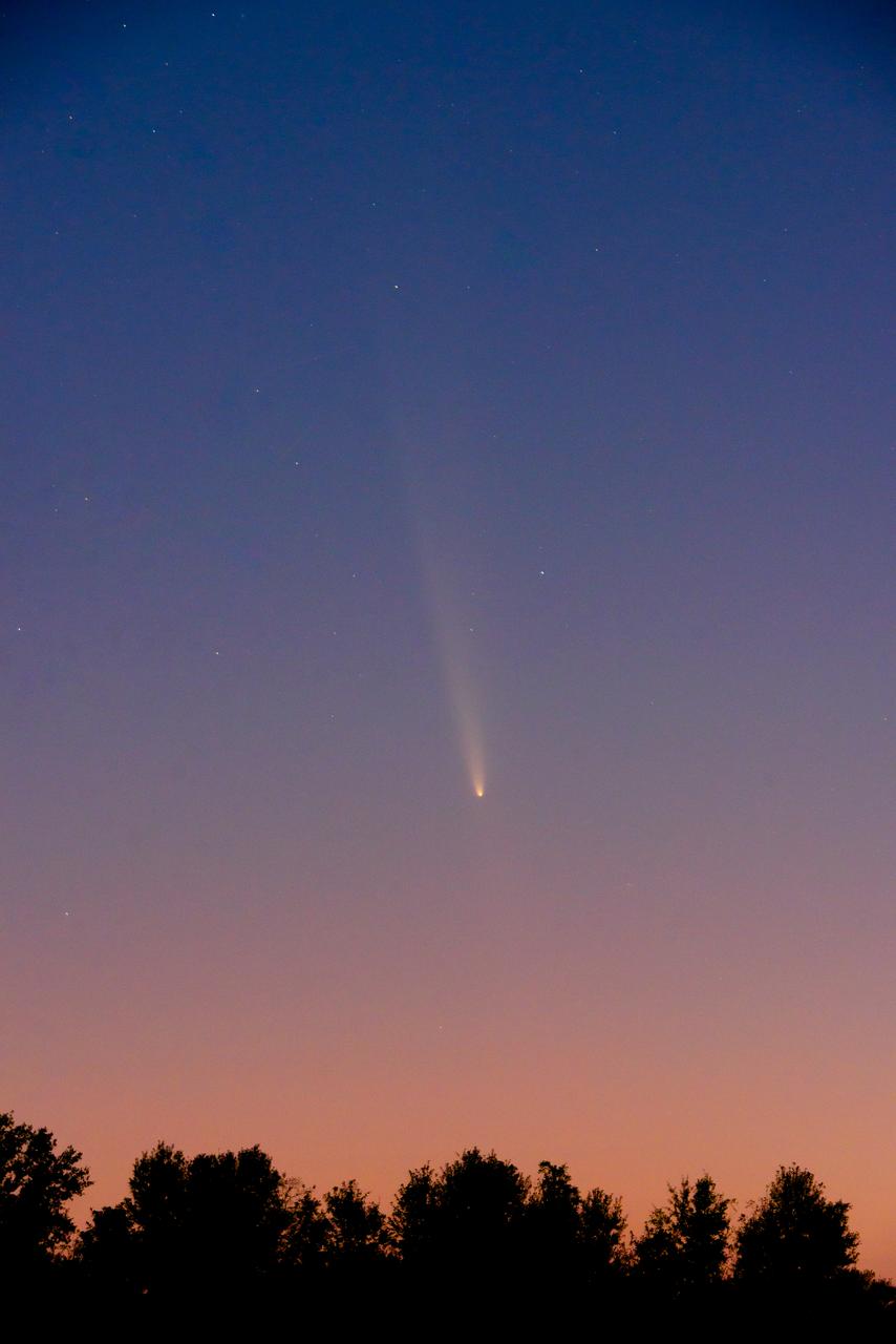
The Oort Cloud comet, called C/2023 A3 Tsuchinshan-ATLAS, passes over Southeast Louisiana near New Orleans, home of NASA’s Michoud Assembly Facility, Sunday, Oct. 13, 2024. The comet is making its first appearance in documented human history; it was last seen in the night sky 80,000 years ago. The Tsuchinshan-ATLAS comet made its first close pass by Earth in mid-October and will remain visible to viewers in the Northern Hemisphere just between the star Arcturus and planet Venus through early November.
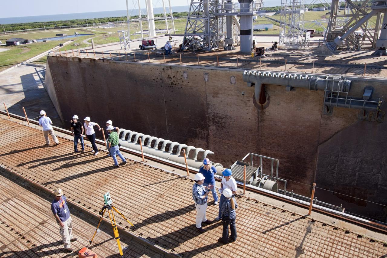
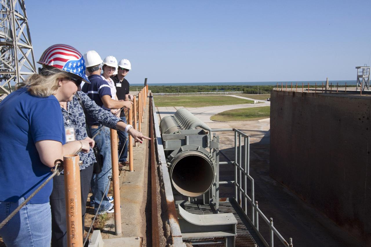
CAPE CANAVERAL, Fla. – Mechanical engineering students from Louisiana State University, the group on the left, joined engineers and scientists at Launch Pad 39B at NASA's Kennedy Space Center in Florida as the students toured the facility to have a look at the flame trench. Designers are looking for new, flame and vibration-resistant materials to line the trench. To help in the search, a team of mechanical engineering students at Louisiana State University are to build a scaled-down version of the flame trench that Kennedy's scientists can use to try out sample materials for the trench. If the samples work in the lab, they can be tried out in the real flame trenches at Launch Pad 39A and 39B. The launch pad has been refurbished extensively and work is continuing to modify the pad to support a variety of launch vehicles in the future. Photo credit: NASA/Jim Grossmann
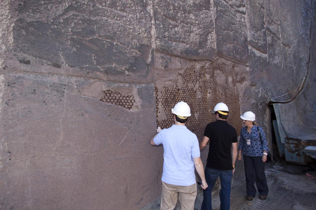
CAPE CANAVERAL, Fla. – Louisiana State University mechanical engineering students Kevin Schenker, from left, and Jacob Koch join Luz Marina Calle, a scientist at NASA's Kennedy Space in Florida, as they examine a portion of the wall of the flame trench at Launch Pad 39B. Designers are looking for new, flame and vibration-resistant materials to line the trench. To help in the search, a team of mechanical engineering students at Louisiana State University are to build a scaled-down version of the flame trench that Kennedy's scientists can use to try out sample materials for the trench. If the samples work in the lab, they can be tried out in the real flame trenches at Launch Pad 39A and 39B. The launch pad has been refurbished extensively and work is continuing to modify the pad to support a variety of launch vehicles in the future. Photo credit: NASA/Jim Grossmann
CAPE CANAVERAL, Fla. – Mechanical engineering students from Louisiana State University joined engineers and scientists at Launch Pad 39B at NASA's Kennedy Space Center in Florida as the students toured the facility to have a look at the flame trench. Designers are looking for new, flame and vibration-resistant materials to line the trench. To help in the search, a team of mechanical engineering students at Louisiana State University are to build a scaled-down version of the flame trench that Kennedy's scientists can use to try out sample materials for the trench. If the samples work in the lab, they can be tried out in the real flame trenches at Launch Pad 39A and 39B. The launch pad has been refurbished extensively and work is continuing to modify the pad to support a variety of launch vehicles in the future. Photo credit: NASA/Jim Grossmann
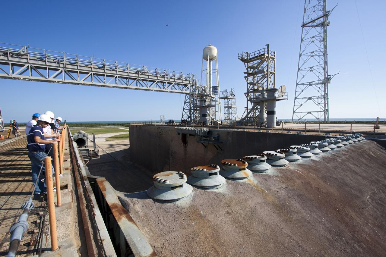
CAPE CANAVERAL, Fla. – Mechanical engineering students from Louisiana State University joined engineers and scientists at Launch Pad 39B at NASA's Kennedy Space Center in Florida as the students toured the facility to have a look at the flame trench. Designers are looking for new, flame and vibration-resistant materials to line the trench. To help in the search, a team of mechanical engineering students at Louisiana State University are to build a scaled-down version of the flame trench that Kennedy's scientists can use to try out sample materials for the trench. If the samples work in the lab, they can be tried out in the real flame trenches at Launch Pad 39A and 39B. The launch pad has been refurbished extensively and work is continuing to modify the pad to support a variety of launch vehicles in the future. Photo credit: NASA/Jim Grossmann
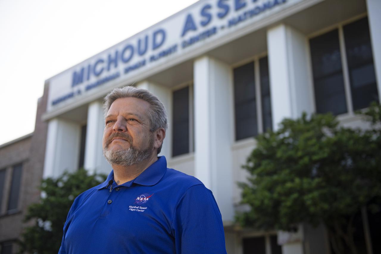
MAF Director Robert Champion stands in front of the Michoud Assembly Facility in New Orleans, Louisiana – America’s Rocket Factory.

This image of the Mississippi River in Mississippi, Arkansas, and Louisiana shows regions of the southern United States that are prone to flooding.
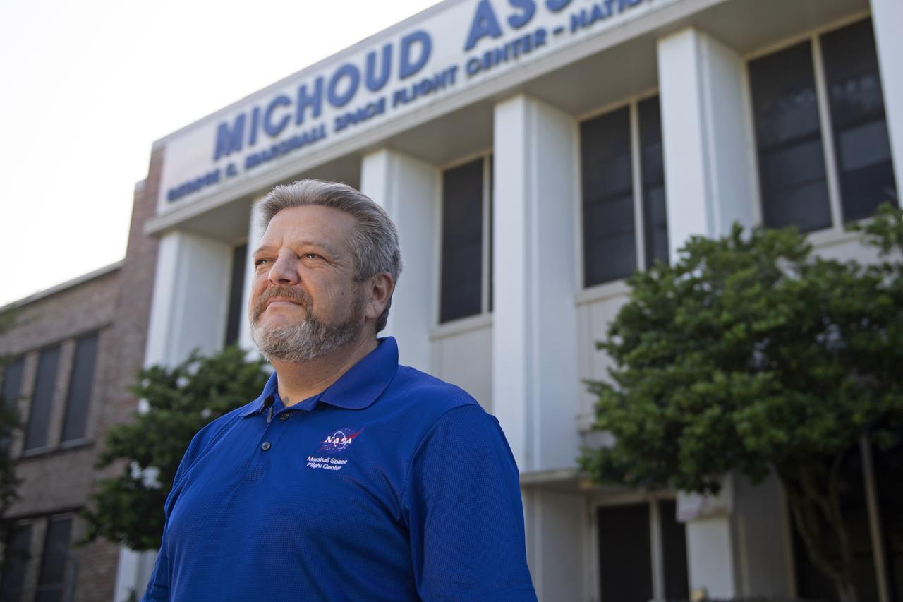
MAF Director Robert Champion stands in front of the Michoud Assembly Facility in New Orleans, Louisiana – America’s Rocket Factory.

MAF Director Robert Champion stands in front of the Michoud Assembly Facility in New Orleans, Louisiana – America’s Rocket Factory.
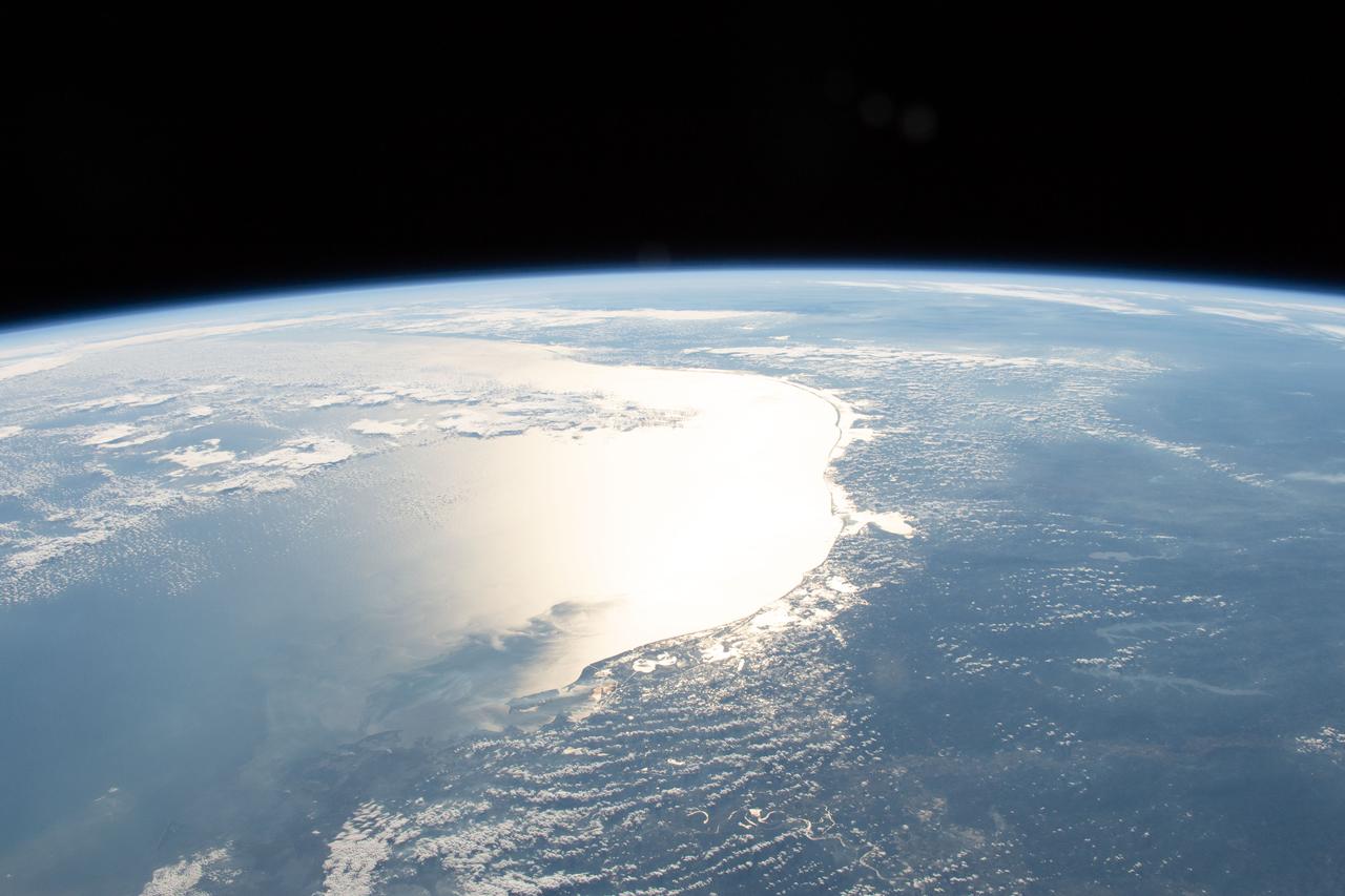
iss058e005915 (Jan. 27, 2019) --- The Sun's glint reflects off the Gulf of Mexico and outlines the coasts of Texas and Louisiana. The International Space Station was orbiting 254 miles above Louisiana when an Expedition 58 crew member photographed the Gulf coast including Matagorda Bay, Galvestion Bay and Sabine Lake.
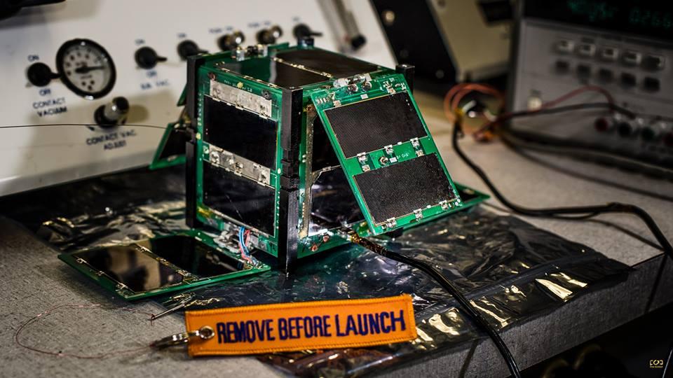
CAPE-2: Cajun Advanced Picosatellite Experiment – ELaNa IV CAPE-2 was developed by students from the University of Louisiana Lafayette to engage, inspire and educate K-12 students to encourage them to pursue STEM careers. The secondary focus is the technology demonstration of deployed solar panels to support the following payloads: text to speech, voice repeater, tweeting, email, file transfer and data collection from buoys. Launched by NASA’s CubeSat Launch Initiative on the ELaNa IV mission as an auxiliary payload aboard the U.S. Air Force-led Operationally Responsive Space (ORS-3) Mission on November 19, 2013.

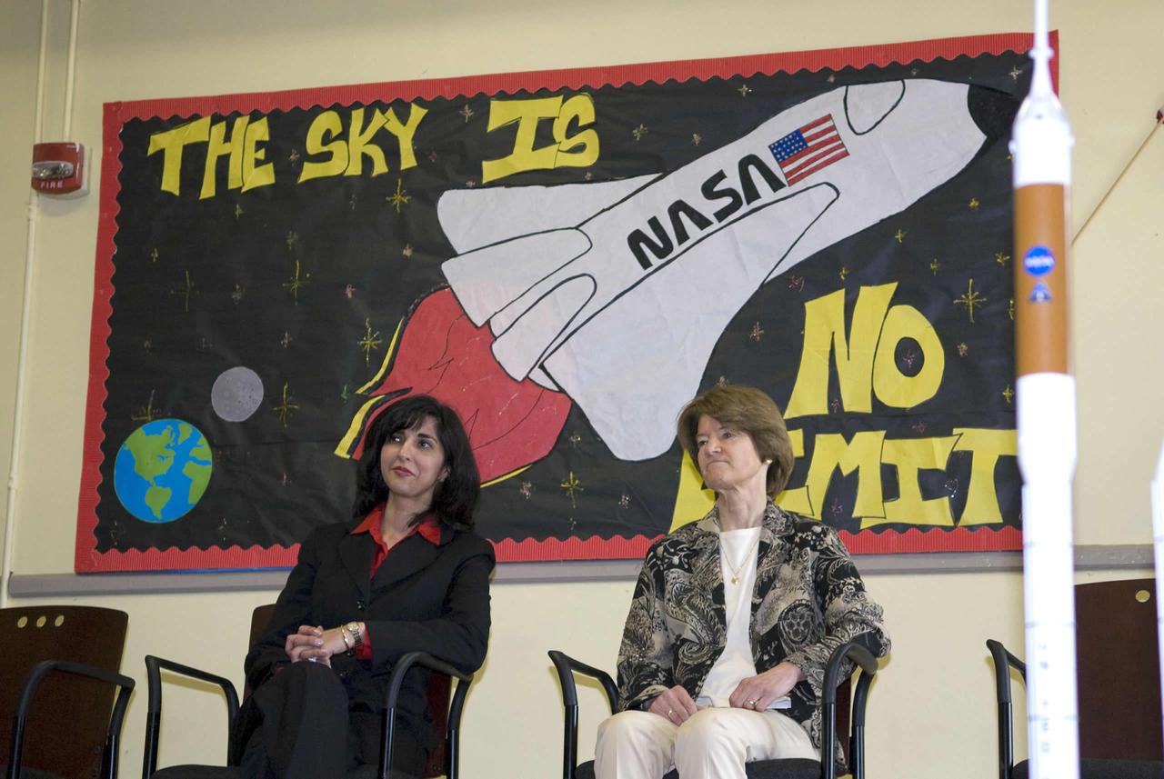
Louisiana First Lady Supriya Jindal fields a question from a student at A.P. Tureaud Elementary School in New Orleans during a March 19 visit. Jindal was joined on her visit by retired astronaut Sally Ride, the first American woman in space.
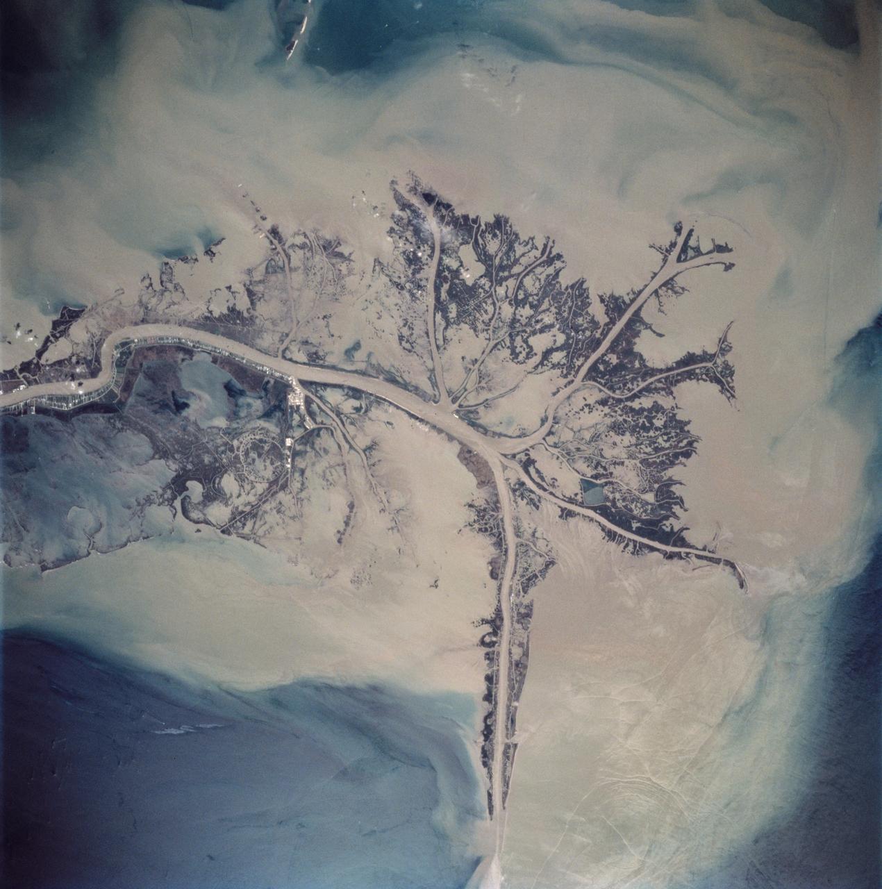
STS062-85-021 (4-18 March 1994) --- The Mississippi River is the largest river system in North America. Its delta is a typical example of the bird's foot class of river deltas. It drains nearly 3 1/2 million square kilometers of real estate and is estimated to carry 2.4 billion kilograms (more than 500 million tons) of sand, silt, and clay to the Gulf of Mexico annually. Most of this sediment is deposited as a delta at the mouth of the river where the velocity of the river water is slowed and its ability to transport sediment is accordingly diminished. Continued deposition at such a site progrades the delta or extends it seaward into the Gulf as much as 150 meters each year until such time as a flooding episode finds a shorter more efficient channel to deliver sediment-laden river waters to the Gulf. At that time the old delta is abandoned and the river begins to build a new delta. In time, compaction of the sediment in the old delta causes it to subside forming first marshes, then bays. This and the modifying effects of coastal waves eventually allow the sea to reclaim much of the temporary land area of the delta. This sequence has repeated itself over and over again at the Mississippi Delta. In this photograph, the present day active Balize delta is shown. According to NASA scientists it is the youngest of the recent delta lobes having begun its seaward pro-gradation only some 600 - 800 years ago. The main channel of the river is 2 kilometers wide and 30 - 40 meters deep. Natural levees here are almost 1 kilometer wide and 3 to 4 meters above sea level. Along the active distributaries of the lower delta, natural levees are less than 100 meters wide and generally less than 0.5 meters above sea level. The bird's foot appearance of deltas such as this is characteristic of low coastal energy conditions - that is, low levels of tidal fluctuation and generally low wave energy. The interdistributary bays are extremely shallow, usually less than a few meters, and contain brackish to normal marine waters except during times of flooding, when fresh water fills the bays. Sedimentation within the bays is very slow, occurring only during flood periods. Along the west side of the river, a highway has been built southeastward to Venice.

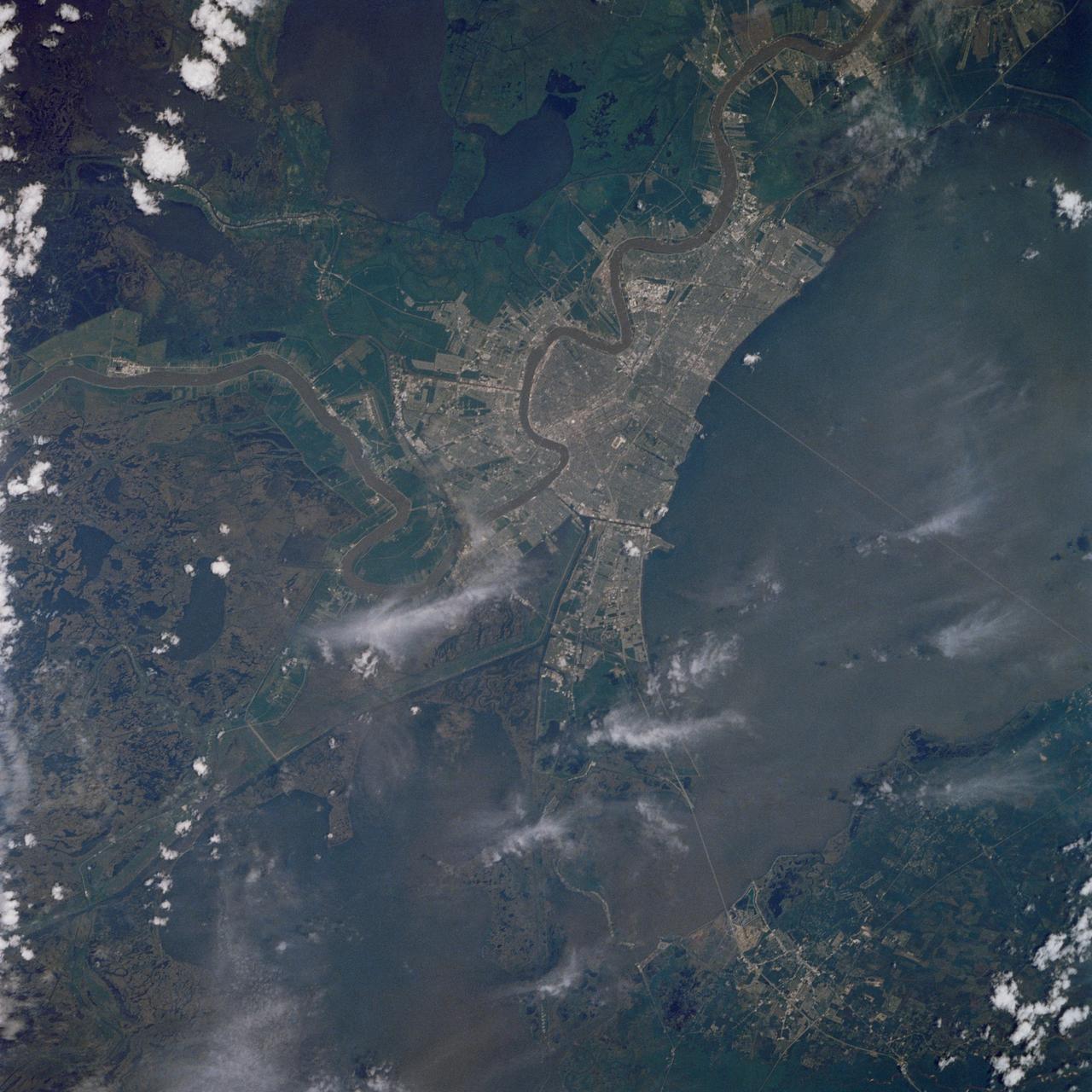
The greater New Orleans area, including portions of Louisiana and Mississippi, as seen from the Apollo 7 spacecraft during its 120th revolution of the earth. Photographed from an altitude of 95 nautical miles, at ground elapsed time of 190 hours and 45 minutes. The largest body of water in the picture is Lake Pontchartrain. The Mississippi River is clearly visible as it meanders past New Orleans. Note highway network, and 25-mile causeway across lake.
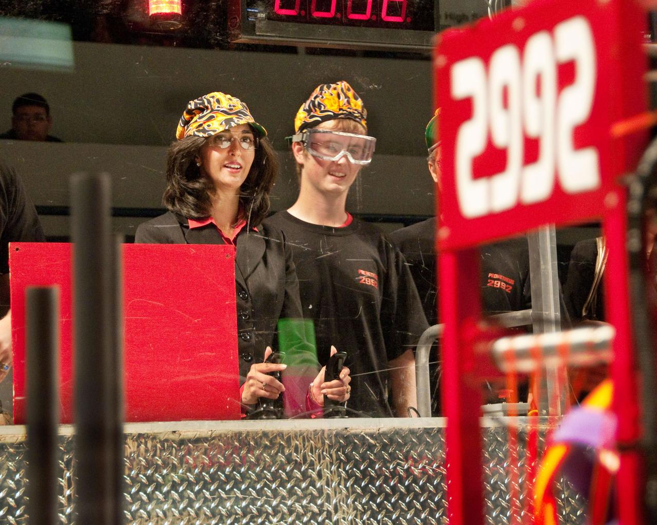
Louisiana First Lady Supriya Jindal takes a turn at the operating controls for a competing robot during the 2009 FIRST Robotics Bayou Regionals tournament in New Orleans on March 19-21. Jindal was hosted during her visit by the NASA Education Office at the John C. Stennis Space Center, a primary sponsor and supporter of the annual robotics competition.
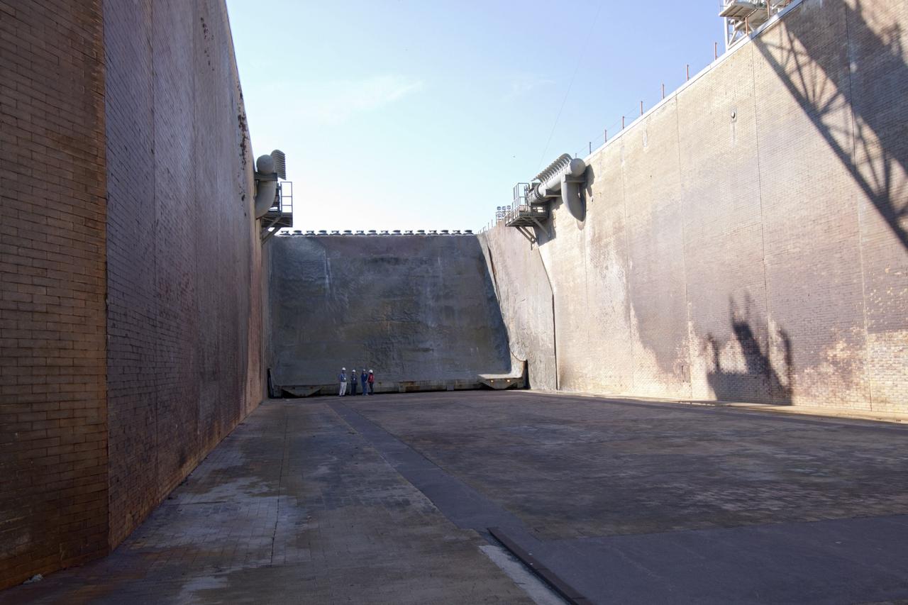
CAPE CANAVERAL, Fla. – The flame trench at Launch Pad 39B at NASA's Kennedy Space Center in Florida endured significant flames, vibrations and other stresses during the space shuttle era. Heading into the future, designers are looking for new, flame and vibration-resistant materials to line the trench. To help in the search, a team of mechanical engineering students at Louisiana State University are to build a scaled-down version of the flame trench that Kennedy's scientists can use to try out sample materials for the trench. If the samples work in the lab, they can be tried out in the real flame trenches at Launch Pad 39A and 39B. The launch pad has been refurbished extensively and work is continuing to modify the pad to support a variety of launch vehicles in the future. Photo credit: NASA/Jim Grossmann
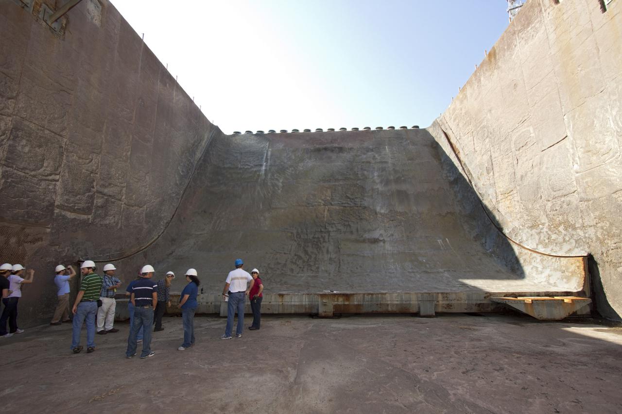
CAPE CANAVERAL, Fla. – Mechanical engineering students from Louisiana State University joined engineers and scientists at Launch Pad 39B at NASA's Kennedy Space Center in Florida as the students toured the facility to have a look at the flame trench. The students, standing on the flame deflector that divides the trench, signed up to help designers looking for new, flame and vibration-resistant materials to line the trench. The students are to build a scaled-down version of the flame trench that Kennedy's scientists can use to try out sample materials for the trench. If the samples work in the lab, they can be tried out in the real flame trenches at Launch Pad 39A and 39B. The launch pad has been refurbished extensively and work is continuing to modify the pad to support a variety of launch vehicles in the future. Photo credit: NASA/Jim Grossmann

CAPE CANAVERAL, Fla. – The flame trench at Launch Pad 39A at NASA's Kennedy Space Center in Florida endured significant flames, vibrations and other stresses during the space shuttle era. Heading into the future, designers are looking for new, flame and vibration-resistant materials to line the trench. To help in the search, a team of mechanical engineering students at Louisiana State University are to build a scaled-down version of the flame trench that Kennedy's scientists can use to try out sample materials for the trench. If the samples work in the lab, they can be tried out in the real flame trenches at Launch Pad 39A and 39B. The launch pad has been refurbished extensively and work is continuing to modify the pad to support a variety of launch vehicles in the future. Photo credit: NASA/Jim Grossmann
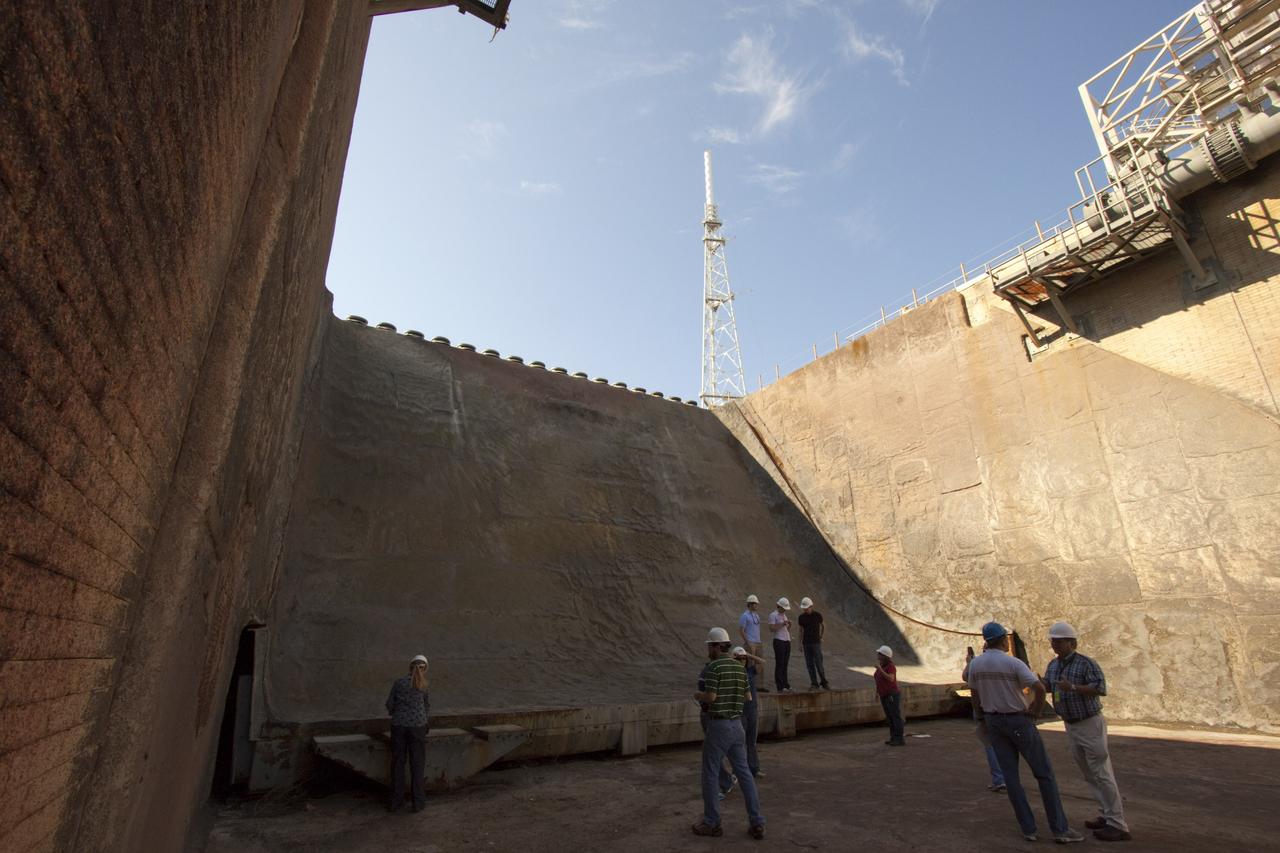
CAPE CANAVERAL, Fla. – Mechanical engineering students from Louisiana State University joined engineers and scientists at Launch Pad 39B at NASA's Kennedy Space Center in Florida as the students toured the facility to have a look at the flame trench. The students, taking pictures of the flame deflector that divides the trench, signed up to help designers looking for new, flame and vibration-resistant materials to line the trench. The students are to build a scaled-down version of the flame trench that Kennedy's scientists can use to try out sample materials for the trench. If the samples work in the lab, they can be tried out in the real flame trenches at Launch Pad 39A and 39B. The launch pad has been refurbished extensively and work is continuing to modify the pad to support a variety of launch vehicles in the future. Photo credit: NASA/Jim Grossmann
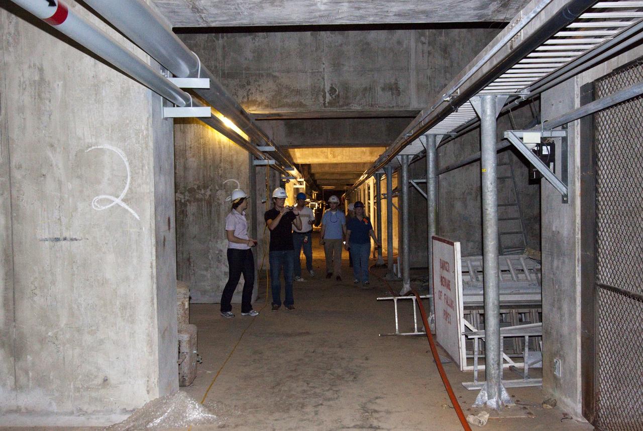
CAPE CANAVERAL, Fla. – Mechanical engineering students from Louisiana State University joined engineers and scientists at Launch Pad 39B at NASA's Kennedy Space Center in Florida as the students toured the facility to have a look at the flame trench. They went inside the pad structure as part of their insight. The students signed up to help designers looking for new, flame and vibration-resistant materials to line the trench. The students are to build a scaled-down version of the flame trench that Kennedy's scientists can use to try out sample materials for the trench. If the samples work in the lab, they can be tried out in the real flame trenches at Launch Pad 39A and 39B. The launch pad has been refurbished extensively and work is continuing to modify the pad to support a variety of launch vehicles in the future. Photo credit: NASA/Jim Grossmann
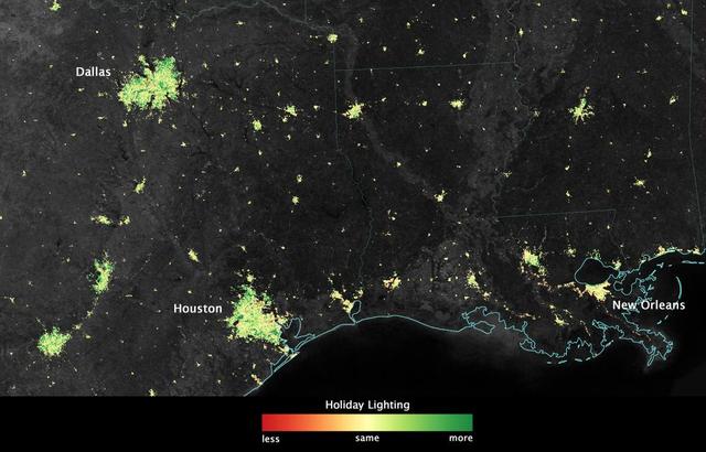
City lights shine brighter during the holidays in the United States when compared with the rest of the year, as shown using a new analysis of daily data from the NASA-NOAA Suomi NPP satellite. Dark green pixels are areas where lights are 50 percent brighter, or more, during December. Because snow reflects so much light, the researchers could only analyze snow-free cities. They focused on the U.S. West Coast from San Francisco and Los Angeles, and cities south of a rough imaginary line from St. Louis to Washington, D.C. Credit: Jesse Allen, NASA’s Earth Observatory Read more: <a href="http://www.nasa.gov/content/goddard/satellite-sees-holiday-lights-brighten-cities." rel="nofollow">www.nasa.gov/content/goddard/satellite-sees-holiday-light...</a>.<b><a href="http://www.nasa.gov/audience/formedia/features/MP_Photo_Guidelines.html" rel="nofollow">NASA image use policy.</a></b> <b><a href="http://www.nasa.gov/centers/goddard/home/index.html" rel="nofollow">NASA Goddard Space Flight Center</a></b> enables NASA’s mission through four scientific endeavors: Earth Science, Heliophysics, Solar System Exploration, and Astrophysics. Goddard plays a leading role in NASA’s accomplishments by contributing compelling scientific knowledge to advance the Agency’s mission. <b>Follow us on <a href="http://twitter.com/NASAGoddardPix" rel="nofollow">Twitter</a></b> <b>Like us on <a href="http://www.facebook.com/pages/Greenbelt-MD/NASA-Goddard/395013845897?ref=tsd" rel="nofollow">Facebook</a></b> <b>Find us on <a href="http://instagram.com/nasagoddard?vm=grid" rel="nofollow">Instagram</a></b>
As one of the best ever views of the city of New Orleans, LA (30.0N, 90.0W) from space, this image allows the study of the city and the region in minute detail. Major city street and highway patterns can easily be traced. Even the Superdome near the old French Quarter can be seen as a large round white circle near the middle of the photo. The French Napoleonic Code land distribution system of long narrow fields fronting the river is also evident.
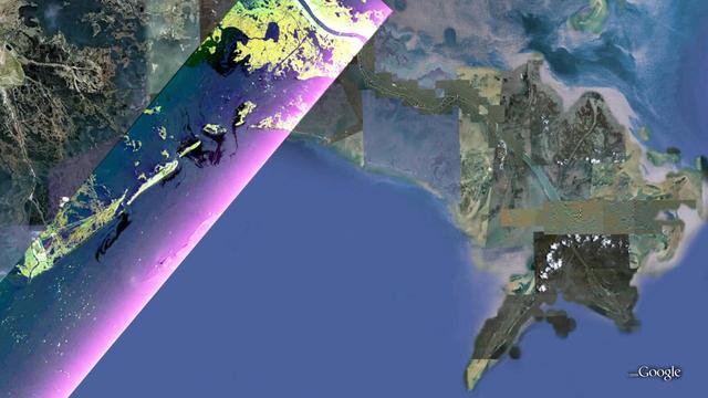
This false-color composite image from NASA UAVSAR taken on June 23, 2010, shows the southern Louisiana coastline, covering the area around Grande Isle and the entrance to Barataria Bay.
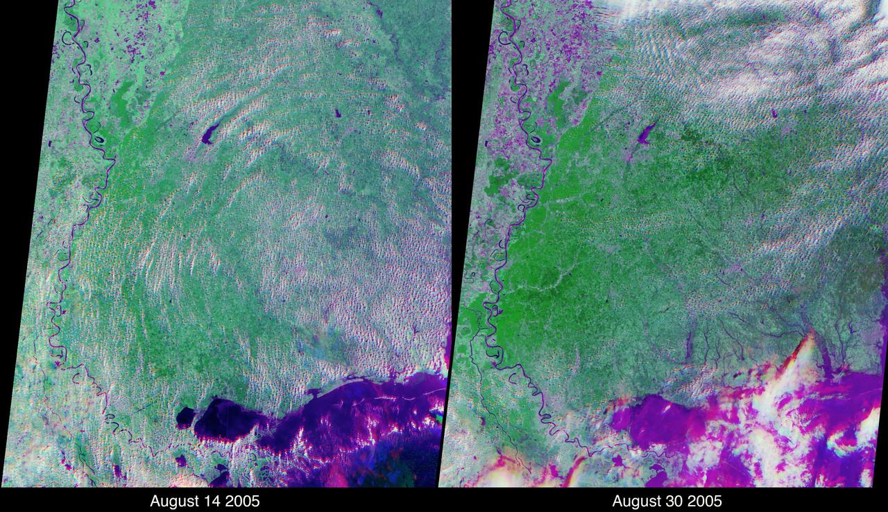
These views of the Louisiana and Mississippi regions were acquired before and one day after Katrina made landfall along the Gulf of Mexico coast. The images were acquired by NASA Terra spacecraft on August 14 and August 30, 2005.
As the remains of Tropical Storm Lee passed over Louisiana on Monday, Sept. 5, 2011, strong, gusty winds on the western side of the storm stoked fires throughout eastern Texas as seen in this image from NASA Terra spacecraft.
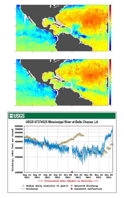
Tropical Storm Lee made landfall over New Orleans on Sept. 2-3, 2011, with predicted rainfall of 15 to 20 inches 38 to 51 centimeters over southern Louisiana. These charts are from NASA Aquarius spacecraft.
iss072e520778 (Jan. 23, 2025) --- The Houston-Galveston area with Trinity Bay, Galveston Bay, and Lake Livingston in Texas is pictured from the International Space Station as it orbited 259 miles above central Louisiana.
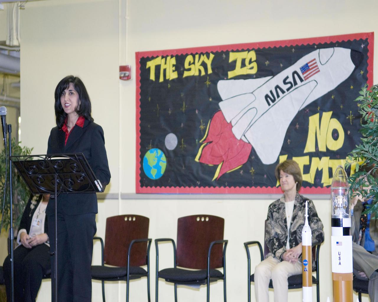
Louisiana First Lady Supriya Jindal (left) speaks to teachers and students at A.P. Tureaud Elementary School in New Orleans during a March 19 visit. At the school, Jindal was joined by retired NASA astronaut Sally Ride, the first American woman in space. Ride was a crew member on space shuttle Challenger during its STS-7 mission in 1983. She also was a crew member of space shuttle discovery on the STS-41 mission in 1984.

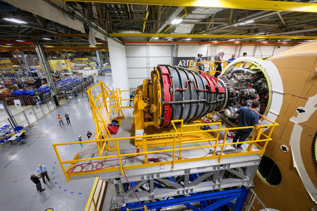
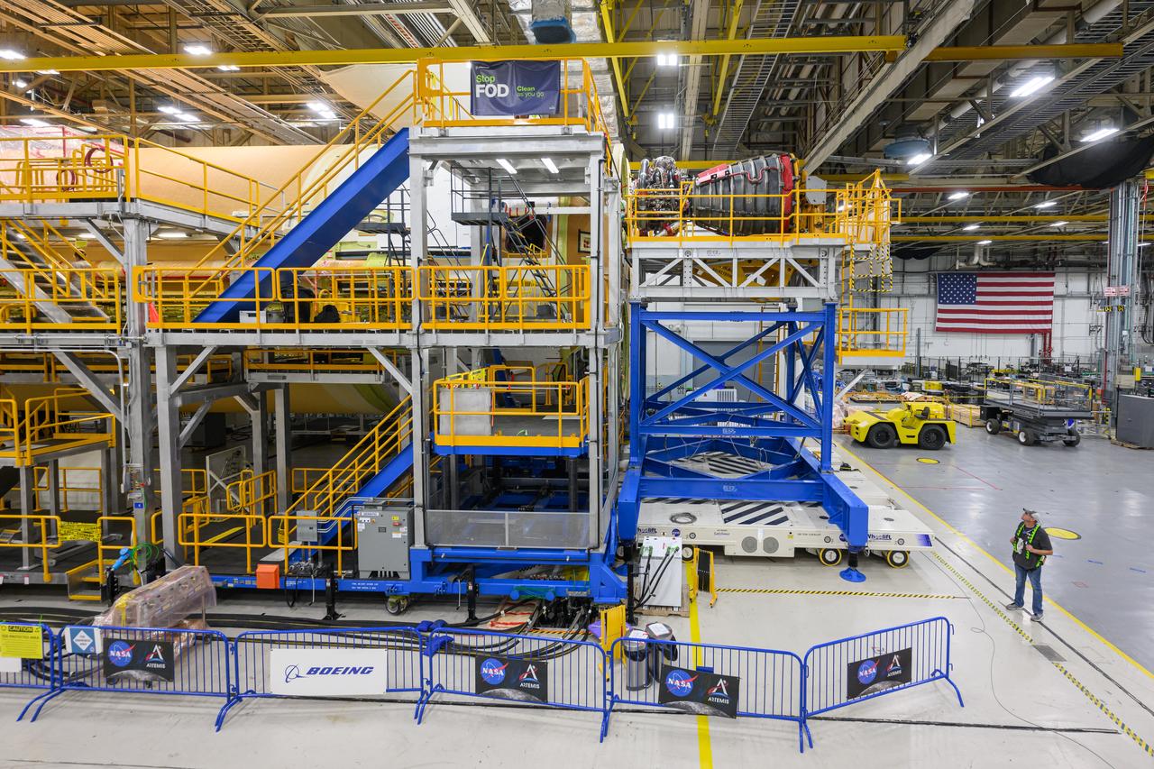
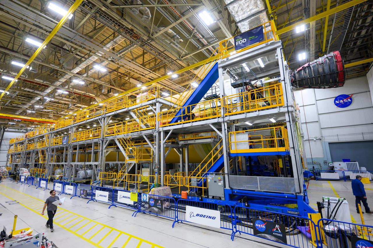
This image shows technicians and engineers move and connect the liquid oxygen tank (LOX) to the intertank as they continue the process of the forward join on the core stage of NASA’s Space Launch System rocket for Artemis II, the first crewed mission of NASA’s Artemis program at NASA’s Michoud Assembly Facility. The forward join connects the forward skirt, the liquid oxygen tank (LOX) and the intertank structures to form the top part of the SLS rocket’s core stage. Now, NASA and Boeing, the SLS prime contractor, will continue to integrate various systems inside the forward part of the core stage and prepare for structural joining of the liquid hydrogen tank and engine section to form the bottom of the stage. Together with its four RS-25 engines, the rocket’s massive 212-foot-tall core stage — the largest stage NASA has ever built — and its twin solid rocket boosters will produce 8.8 million pounds of thrust to send NASA’s Orion spacecraft, astronauts and supplies beyond Earth’s orbit to the Moon and, ultimately, Mars. Offering more payload mass, volume capability and energy to speed missions through space, the SLS rocket, along with NASA’s Gateway in lunar orbit, the Human Landing System, and Orion spacecraft, is part of NASA’s backbone for deep space exploration and the Artemis lunar program. No other rocket is capable of carrying astronauts in Orion around the Moon in a single mission.

This image shows technicians and engineers move and connect the liquid oxygen tank (LOX) to the intertank as they continue the process of the forward join on the core stage of NASA’s Space Launch System rocket for Artemis II, the first crewed mission of NASA’s Artemis program at NASA’s Michoud Assembly Facility. The forward join connects the forward skirt, the liquid oxygen tank (LOX) and the intertank structures to form the top part of the SLS rocket’s core stage. Now, NASA and Boeing, the SLS prime contractor, will continue to integrate various systems inside the forward part of the core stage and prepare for structural joining of the liquid hydrogen tank and engine section to form the bottom of the stage. Together with its four RS-25 engines, the rocket’s massive 212-foot-tall core stage — the largest stage NASA has ever built — and its twin solid rocket boosters will produce 8.8 million pounds of thrust to send NASA’s Orion spacecraft, astronauts and supplies beyond Earth’s orbit to the Moon and, ultimately, Mars. Offering more payload mass, volume capability and energy to speed missions through space, the SLS rocket, along with NASA’s Gateway in lunar orbit, the Human Landing System, and Orion spacecraft, is part of NASA’s backbone for deep space exploration and the Artemis lunar program. No other rocket is capable of carrying astronauts in Orion around the Moon in a single mission.

This image shows technicians and engineers move and connect the liquid oxygen tank (LOX) to the intertank as they continue the process of the forward join on the core stage of NASA’s Space Launch System rocket for Artemis II, the first crewed mission of NASA’s Artemis program at NASA’s Michoud Assembly Facility. The forward join connects the forward skirt, the liquid oxygen tank (LOX) and the intertank structures to form the top part of the SLS rocket’s core stage. Now, NASA and Boeing, the SLS prime contractor, will continue to integrate various systems inside the forward part of the core stage and prepare for structural joining of the liquid hydrogen tank and engine section to form the bottom of the stage. Together with its four RS-25 engines, the rocket’s massive 212-foot-tall core stage — the largest stage NASA has ever built — and its twin solid rocket boosters will produce 8.8 million pounds of thrust to send NASA’s Orion spacecraft, astronauts and supplies beyond Earth’s orbit to the Moon and, ultimately, Mars. Offering more payload mass, volume capability and energy to speed missions through space, the SLS rocket, along with NASA’s Gateway in lunar orbit, the Human Landing System, and Orion spacecraft, is part of NASA’s backbone for deep space exploration and the Artemis lunar program. No other rocket is capable of carrying astronauts in Orion around the Moon in a single mission.

This image shows technicians and engineers move and connect the liquid oxygen tank (LOX) to the intertank as they continue the process of the forward join on the core stage of NASA’s Space Launch System rocket for Artemis II, the first crewed mission of NASA’s Artemis program at NASA’s Michoud Assembly Facility. The forward join connects the forward skirt, the liquid oxygen tank (LOX) and the intertank structures to form the top part of the SLS rocket’s core stage. Now, NASA and Boeing, the SLS prime contractor, will continue to integrate various systems inside the forward part of the core stage and prepare for structural joining of the liquid hydrogen tank and engine section to form the bottom of the stage. Together with its four RS-25 engines, the rocket’s massive 212-foot-tall core stage — the largest stage NASA has ever built — and its twin solid rocket boosters will produce 8.8 million pounds of thrust to send NASA’s Orion spacecraft, astronauts and supplies beyond Earth’s orbit to the Moon and, ultimately, Mars. Offering more payload mass, volume capability and energy to speed missions through space, the SLS rocket, along with NASA’s Gateway in lunar orbit, the Human Landing System, and Orion spacecraft, is part of NASA’s backbone for deep space exploration and the Artemis lunar program. No other rocket is capable of carrying astronauts in Orion around the Moon in a single mission.
NASA officials were joined by Louisiana Gov. John Bel Edwards and New Orleans Mayor Mitch Landrieu, who toured the Michoud Assembly Facility in New Orleans and got a first-hand look at NASA’s new deep space vehicles being built at the facility.
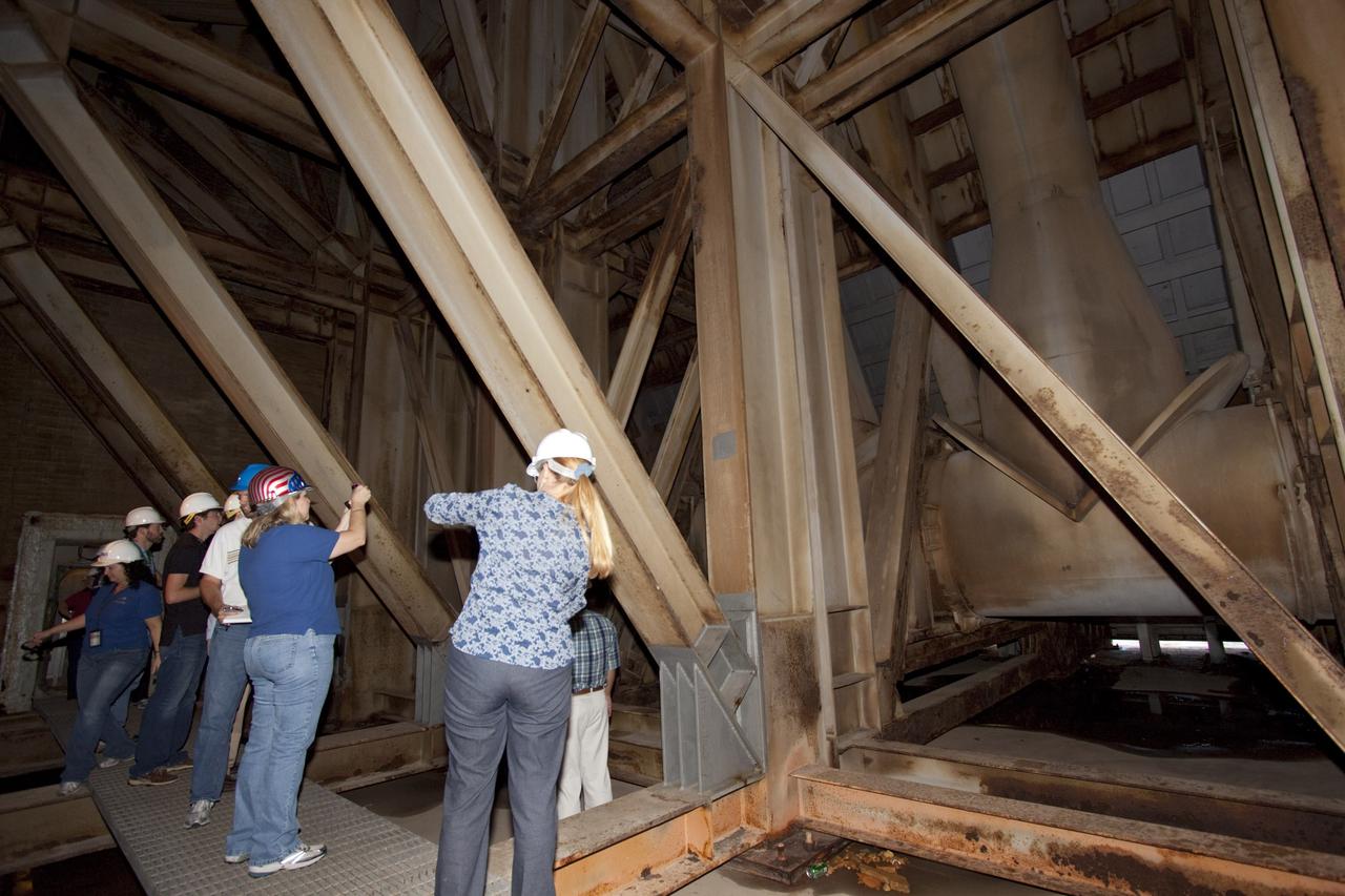
CAPE CANAVERAL, Fla. – Mechanical engineering students from Louisiana State University joined engineers and scientists at Launch Pad 39B at NASA's Kennedy Space Center in Florida as the students toured the facility to have a look at the flame trench. They went inside the pad structure to the area inside the flame deflector which divides the flame trench and funnels exhaust away from a shuttle at liftoff. The flame deflector, which is about 40-feet tall, is essentially hollow inside and braced by steel beams. The students signed up to help designers looking for new, flame and vibration-resistant materials to line the trench. The students are to build a scaled-down version of the flame trench that Kennedy's scientists can use to try out sample materials for the trench. If the samples work in the lab, they can be tried out in the real flame trenches at Launch Pad 39A and 39B. The launch pad has been refurbished extensively and work is continuing to modify the pad to support a variety of launch vehicles in the future. Photo credit: NASA/Jim Grossmann

iss046e005351 (1/5/2016) --- The Expedition 46 crew photographed an Earth observation night pass over the Gulf of Mexico. The view looks toward the northeast and includes Texas and Louisiana gulf coasts, as well as major cities in Texas, Louisiana, Mississippi, Alabama, Oklahoma, Arkansas, Tennessee and more.
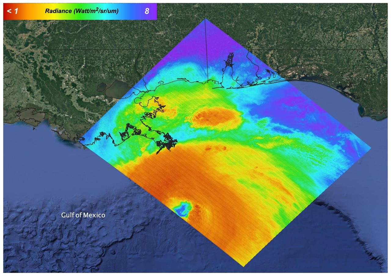
On August 27, 2021 Ida crossed over Cuba as a Category 1 Storm. 48 hours later the storm intensified to a Category 4 before making landfall on the coast of Louisiana. The storm was the second most destructive storm to ever make landfall on the Louisiana coast with sustained winds over 150 mph (240 km/h). The rapid intensification process that the storm system underwent is not well understood. Satellite images such as this are helpful as scientists attempt to understand new weather patterns that are emerging with Global Climate Change. Tasked with detecting plant water use and stress, ECOSTRESS's primary mission is to measure the temperature of plants heating up as they run out of water. But it can also measure and track heat-related phenomena like wildfires, heat waves, and volcanoes. ECOSTRESS observations have a spatial resolution of about 77 by 77 yards (70 by 70 meters), which enables researchers to study surface-temperature conditions down to the size of a football field. Due to the space station's unique orbit, the mission can acquire images of the same regions at different times of the day, as opposed to crossing over each area at the same time of day like satellites in other orbits do. This is advantageous when monitoring plant stress in the same area throughout the day, for example. https://photojournal.jpl.nasa.gov/catalog/PIA24210
Technicians at NASA’s Michoud Assembly Facility move the intertank of NASA’s Space Launch System rocket for Artemis III to Cell G on October 26, 2022 to await application of the thermal protection system. Thermal protection systems protect space vehicles from aerodynamic heating during entry to planet atmosphere and re-entry to earth atmosphere. The intertank lays between the liquid hydrogen tank and liquid oxygen tank. Together with the engine section and the forward skirt, they comprise the SLS core stage. The liquid hydrogen tank and liquid oxygen tank hold 733,000 gallons of propellant to power the stage’s four RS-25 engines needed for liftoff and Artemis missions to the Moon and future missions to Mars.
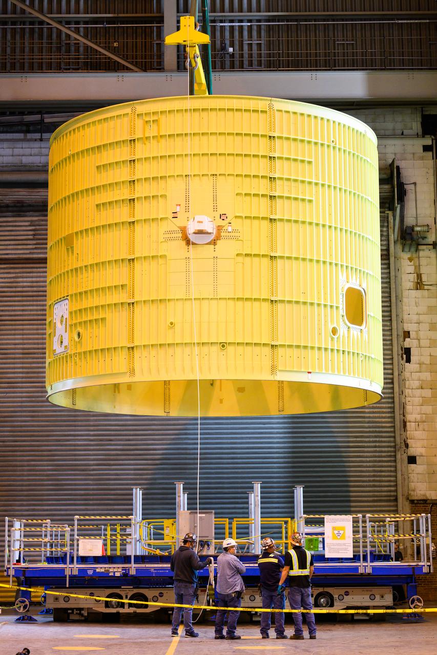
Technicians at NASA’s Michoud Assembly Facility move the intertank of NASA’s Space Launch System rocket for Artemis III to Cell G on October 26, 2022 to await application of the thermal protection system. Thermal protection systems protect space vehicles from aerodynamic heating during entry to planet atmosphere and re-entry to earth atmosphere. The intertank lays between the liquid hydrogen tank and liquid oxygen tank. Together with the engine section and the forward skirt, they comprise the SLS core stage. The liquid hydrogen tank and liquid oxygen tank hold 733,000 gallons of propellant to power the stage’s four RS-25 engines needed for liftoff and Artemis missions to the Moon and future missions to Mars.
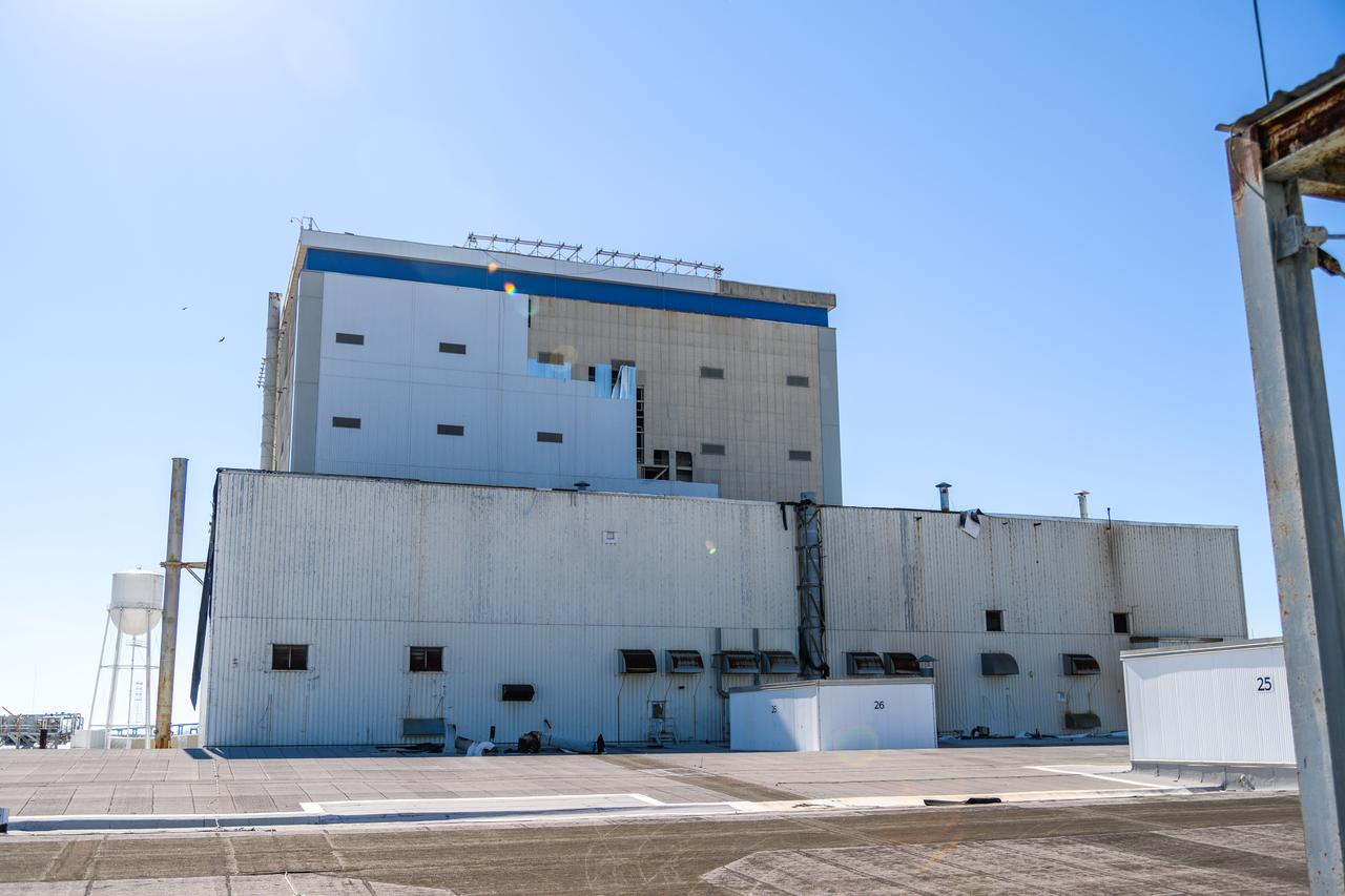
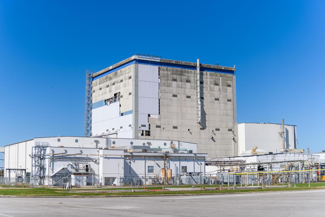
Hurricane Zeta damage to NASA’s Michoud Assembly Facility – East side of Bldg. 110 the Vertical Assembly Building (VAB).
/MAF_20221027_CS3_IT_lifttoG-epb_004(1)~medium.jpg)
Technicians at NASA’s Michoud Assembly Facility move the intertank of NASA’s Space Launch System rocket for Artemis III to Cell G on October 26, 2022 to await application of the thermal protection system. Thermal protection systems protect space vehicles from aerodynamic heating during entry to planet atmosphere and re-entry to earth atmosphere. The intertank lays between the liquid hydrogen tank and liquid oxygen tank. Together with the engine section and the forward skirt, they comprise the SLS core stage. The liquid hydrogen tank and liquid oxygen tank hold 733,000 gallons of propellant to power the stage’s four RS-25 engines needed for liftoff and Artemis missions to the Moon and future missions to Mars.
Hurricane Zeta damage to NASA’s Michoud Assembly Facility – East side of Bldg. 110 the Vertical Assembly Building (VAB).
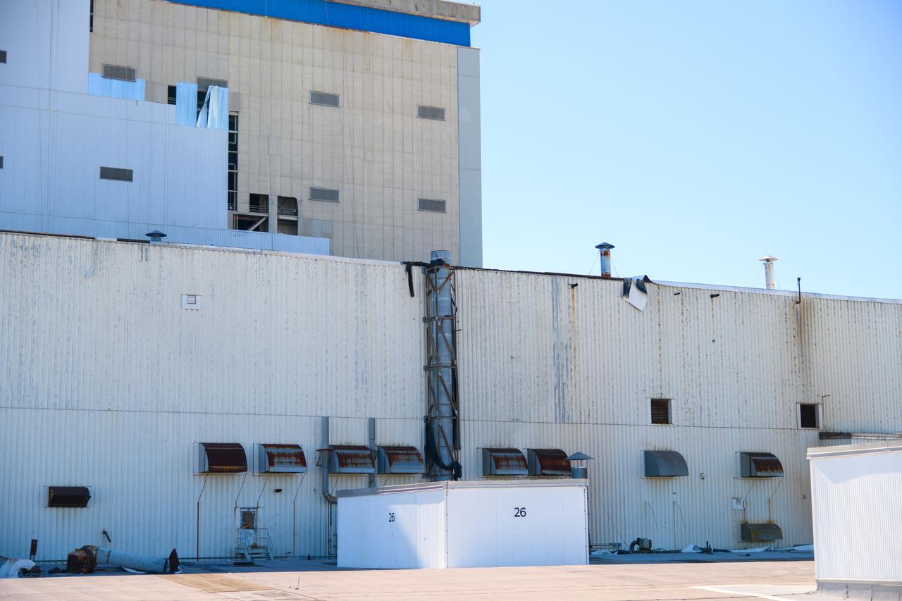
Hurricane Zeta damage to NASA’s Michoud Assembly Facility – South side of Bldg. 110 the Vertical Assembly Building (VAB).
Technicians at NASA’s Michoud Assembly Facility move the intertank of NASA’s Space Launch System rocket for Artemis III to Cell G on October 26, 2022 to await application of the thermal protection system. Thermal protection systems protect space vehicles from aerodynamic heating during entry to planet atmosphere and re-entry to earth atmosphere. The intertank lays between the liquid hydrogen tank and liquid oxygen tank. Together with the engine section and the forward skirt, they comprise the SLS core stage. The liquid hydrogen tank and liquid oxygen tank hold 733,000 gallons of propellant to power the stage’s four RS-25 engines needed for liftoff and Artemis missions to the Moon and future missions to Mars.
Technicians at NASA’s Michoud Assembly Facility move the intertank of NASA’s Space Launch System rocket for Artemis III to Cell G on October 26, 2022 to await application of the thermal protection system. Thermal protection systems protect space vehicles from aerodynamic heating during entry to planet atmosphere and re-entry to earth atmosphere. The intertank lays between the liquid hydrogen tank and liquid oxygen tank. Together with the engine section and the forward skirt, they comprise the SLS core stage. The liquid hydrogen tank and liquid oxygen tank hold 733,000 gallons of propellant to power the stage’s four RS-25 engines needed for liftoff and Artemis missions to the Moon and future missions to Mars.
Technicians at NASA’s Michoud Assembly Facility move the intertank of NASA’s Space Launch System rocket for Artemis III to Cell G on October 26, 2022 to await application of the thermal protection system. Thermal protection systems protect space vehicles from aerodynamic heating during entry to planet atmosphere and re-entry to earth atmosphere. The intertank lays between the liquid hydrogen tank and liquid oxygen tank. Together with the engine section and the forward skirt, they comprise the SLS core stage. The liquid hydrogen tank and liquid oxygen tank hold 733,000 gallons of propellant to power the stage’s four RS-25 engines needed for liftoff and Artemis missions to the Moon and future missions to Mars.
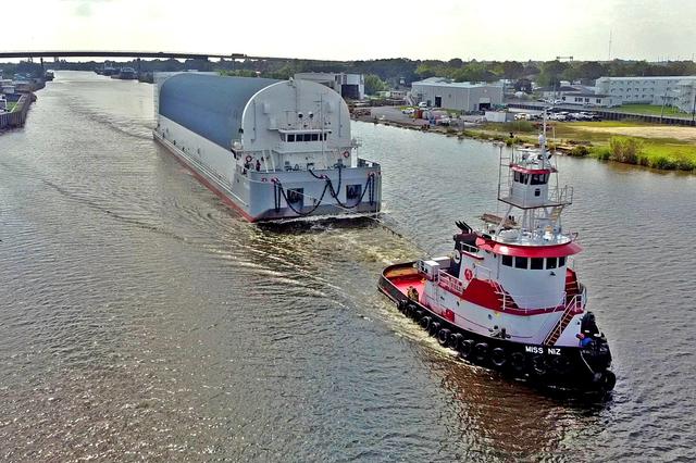
Pegasus on the ICWW at Larose, LA as it makes its way from the Thoma-Sea Shipyard in Houma, LA to Stennis Space Center in Mississippi on Tuesday, October 13, 2020.
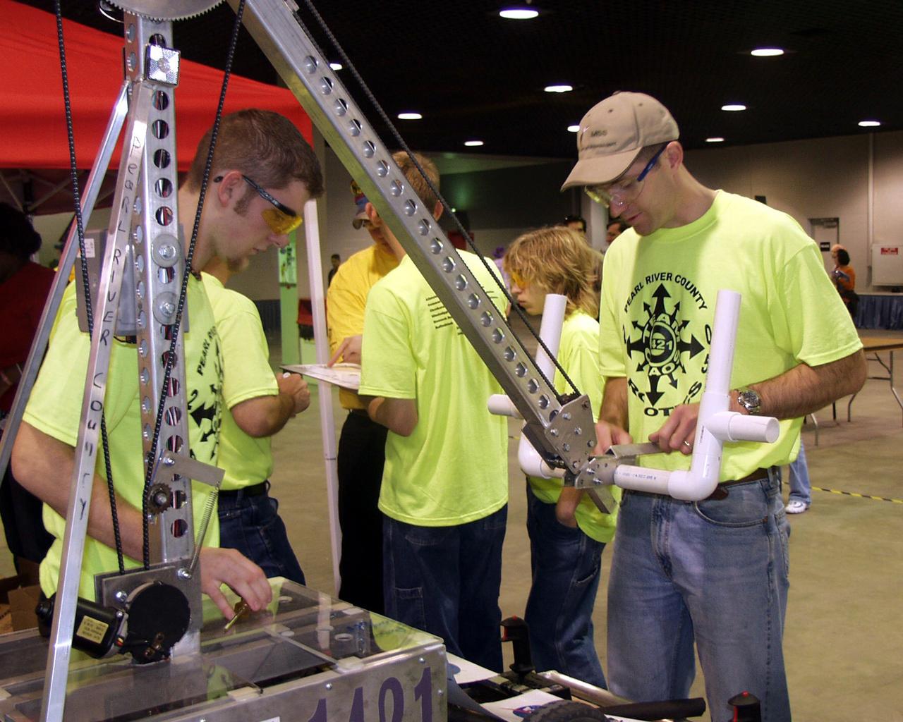
Engineers from SSC mentor teams of students from Mississippi and Louisiana competing in the FIRST Robotics Competition.
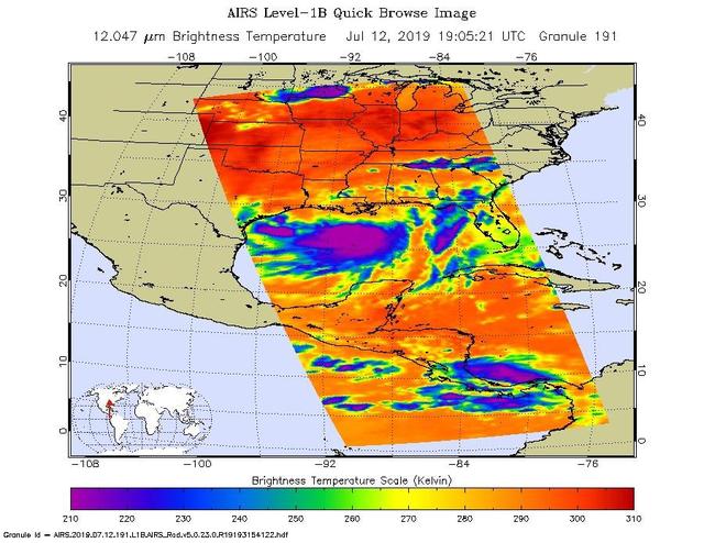
NASA's AIRS instrument imaged Tropical Storm Barry on the afternoon of July 12, 2019, a day before the storm is expected to make landfall on the Louisiana Coast. The infrared image shows very cold clouds that have been carried high into the atmosphere by deep thunderstorms in purple. These clouds are associated with heavy rainfall. Warmer areas with shallower rain clouds are shown in blue and green. And the orange and red areas represent mostly cloud-free air. https://photojournal.jpl.nasa.gov/catalog/PIA23355
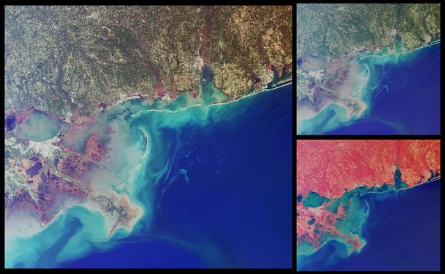
This set of images from NASA Terra satellit highlights coastal areas of four states along the Gulf of Mexico: Louisiana, Mississippi, Alabama and part of the Florida panhandle. The images were acquired on October 15, 2001 Terra orbit 9718.
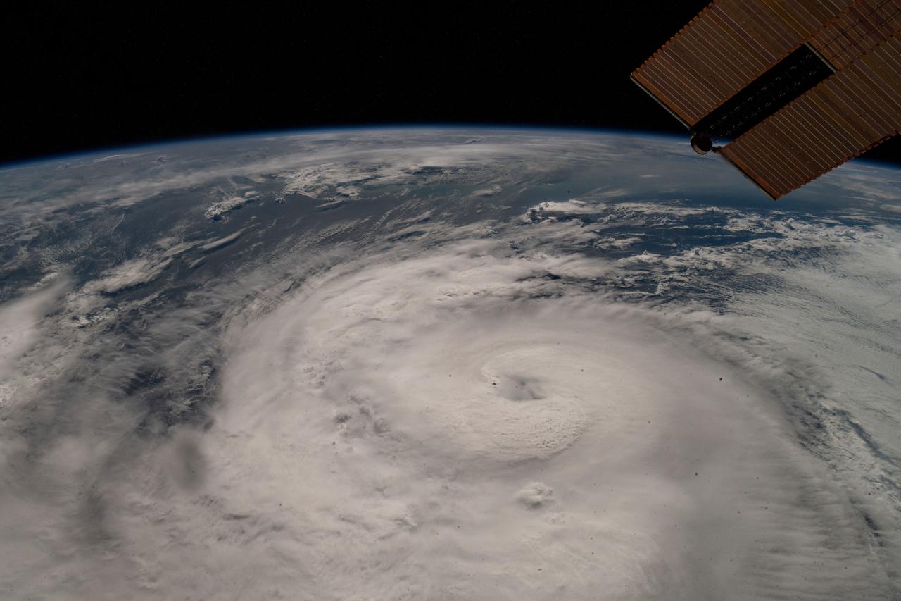
iss064e002148 (Oct. 28, 2020) --- Hurricane Zeta was pictured from the International Space Station as the category two storm churned in the Gulf of Mexico nearing Louisiana.
Louisiana first lady Supriya Jindal joins astronaut Sally Ride in speaking to teachers and students at A.P. Tureaud Elementary School in New Orleans.

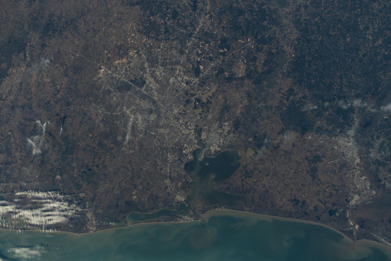
iss063e093260 (Sept. 19, 2020) --- This oblique view of Houston, Texas, was taken from the International Space Station as it orbited above northern Louisiana.

Louisiana first lady Supriya Jindal joins astronaut Sally Ride in speaking to teachers and students at A.P. Tureaud Elementary School in New Orleans.
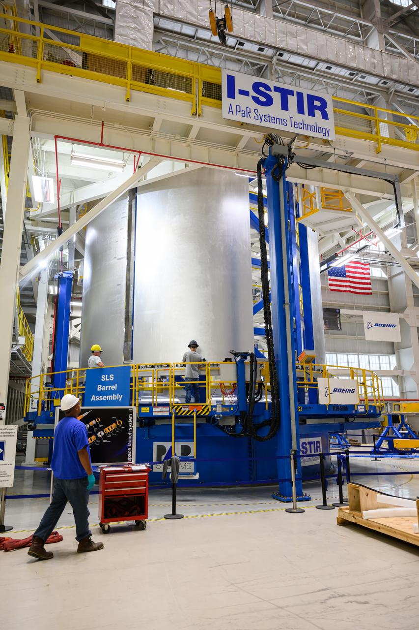
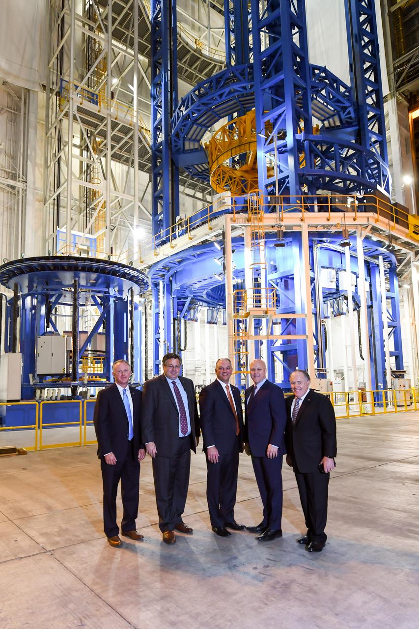
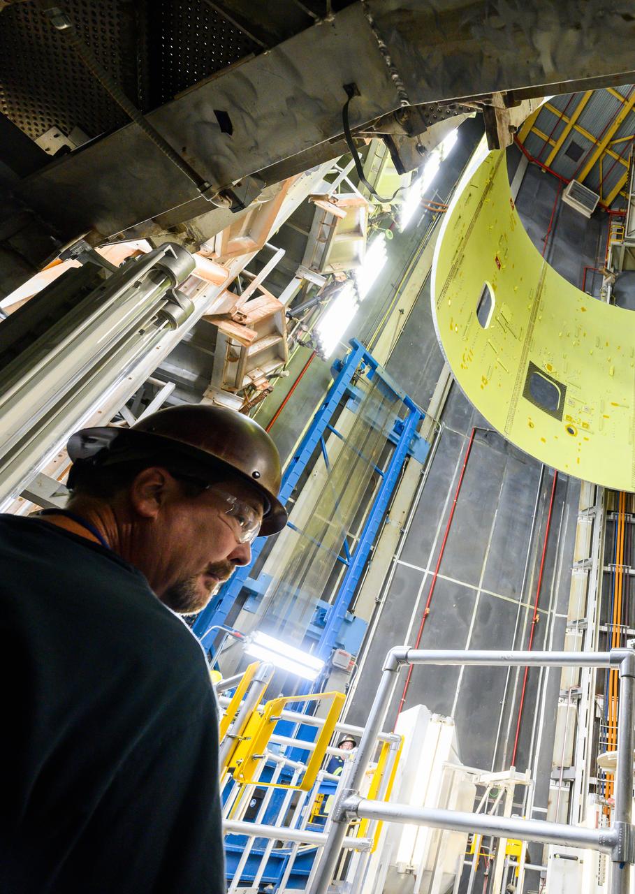
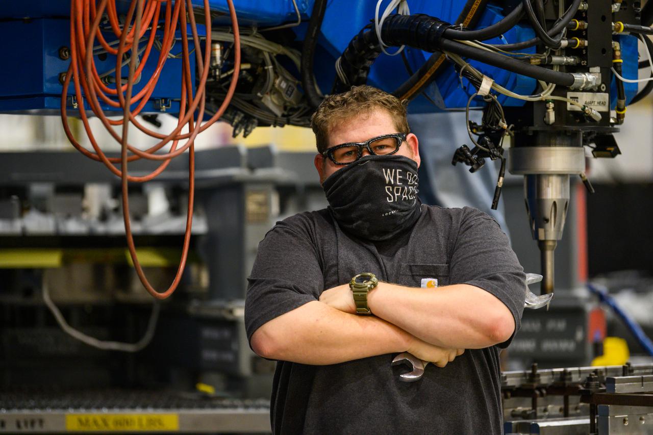
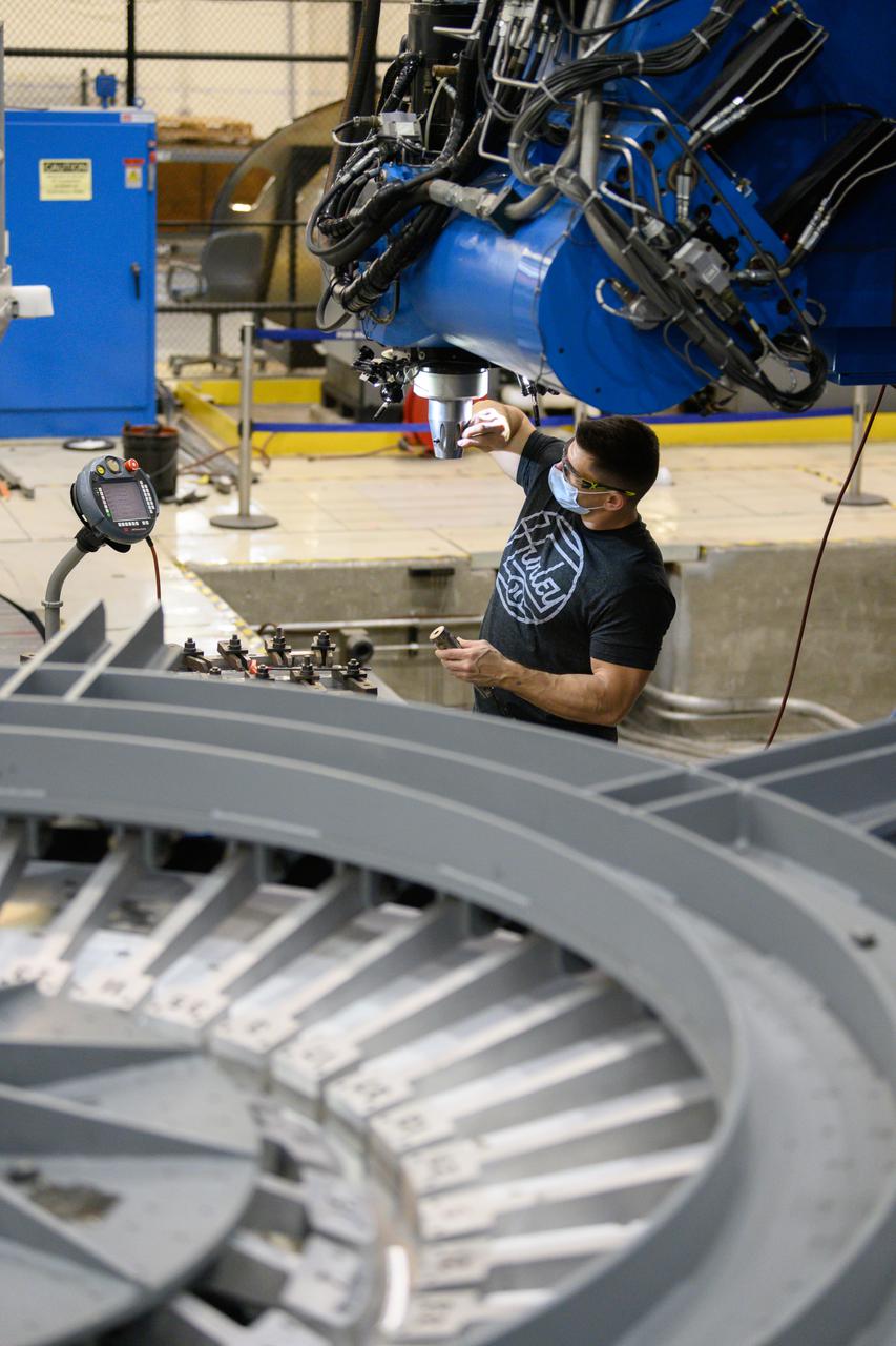
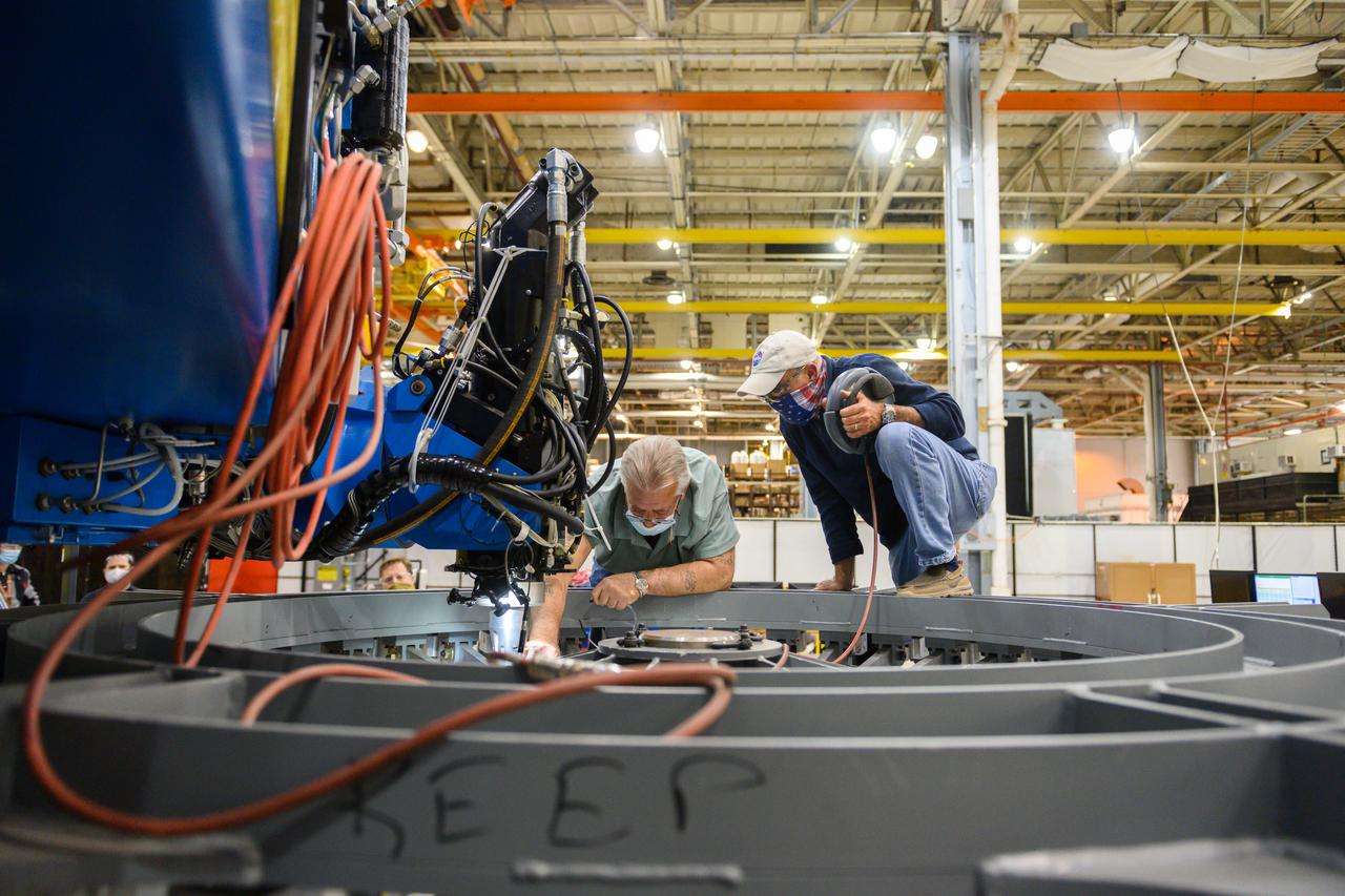
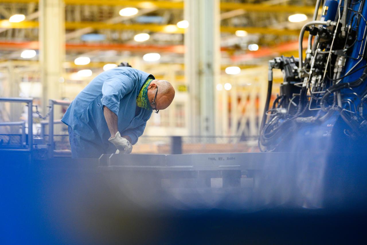
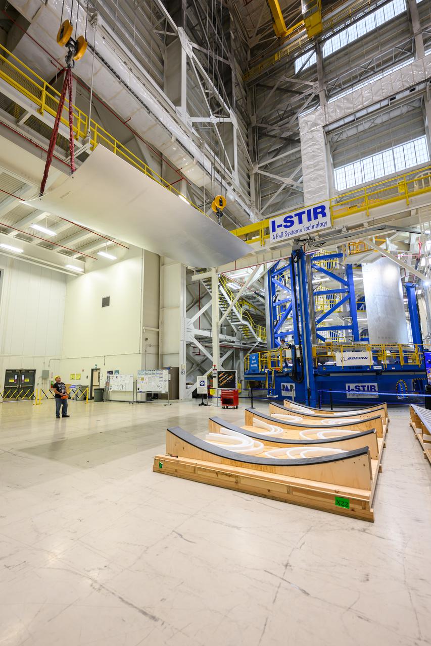
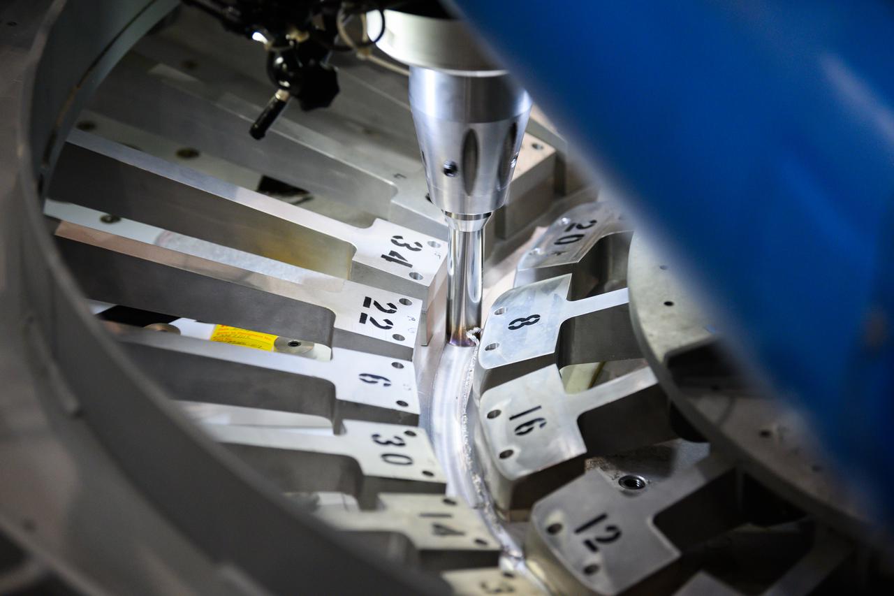
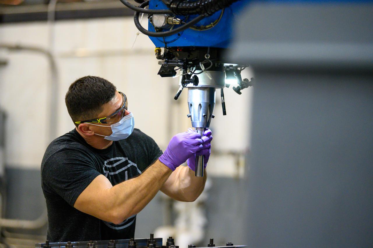
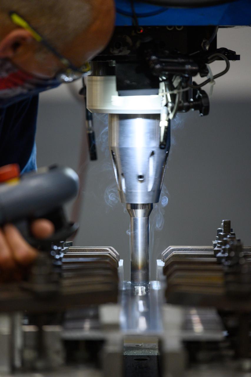
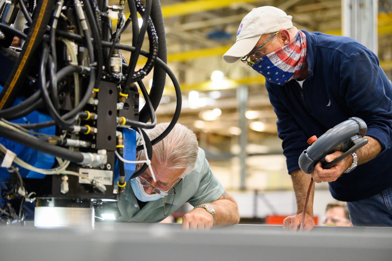
Crews at NASA’s Michoud Assembly Facility in New Orleans load alluminum alloy panels into the Vertical Weld Center June 1. The Vertical Weld Center is a friction-stir weld tool for the large structures of the core stage for the SLS (Space Launch System) rocket. Teams load the panels into the VWC using an overhead crane system, then multiple panels are welded together to create entire barrels. The panels in these images are some of the five barrels that will form the SLS liquid hydrogen propellant tank for the SLS rocket that will power NASA’s Artemis IV mission, which is also the first flight of SLS in its more powerful Block 1B configuration. The SLS core stage is made up of five unique elements: the forward skirt, liquid oxygen tank, intertank, liquid hydrogen tank, and the engine section. The liquid hydrogen propellant tank holds 537,000 gallons of liquid hydrogen cooled to minus 432 degrees Fahrenheit and sits between the core stage’s intertank and engine section. The liquid hydrogen hardware, along with the liquid oxygen tank, provides propellant to the four RS-25 engines at the bottom of the core stage to produce more than two million pounds of thrust to help launch the Artemis IV mission to the Moon. Together with its four RS-25 engines, the rocket’s massive 212-foot-tall core stage — the largest stage NASA has ever built — and its twin solid rocket boosters produce 8.8 million pounds of thrust to send NASA’s Orion spacecraft, astronauts and supplies beyond Earth’s orbit to the Moon. NASA is working to land the first woman and first person of color on the Moon under Artemis. SLS is part of NASA’s backbone for deep space exploration, along with Orion and the Gateway in orbit around the Moon. SLS is the only rocket that can send Orion, astronauts, and supplies to the Moon in a single mission.
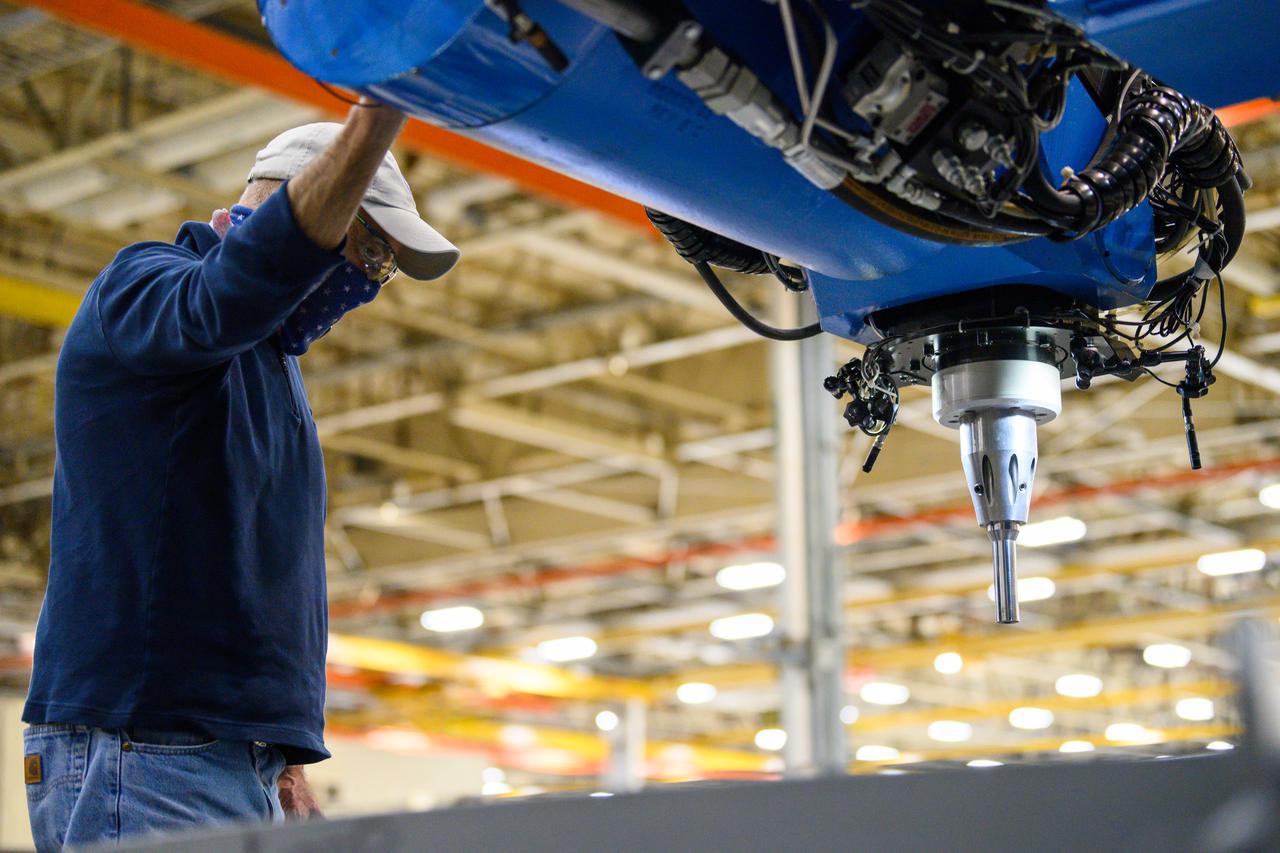
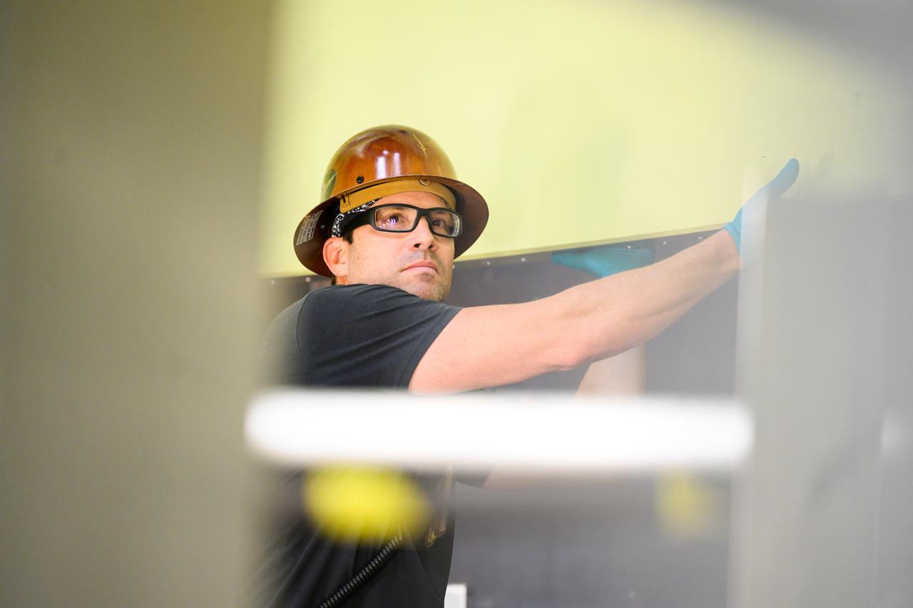
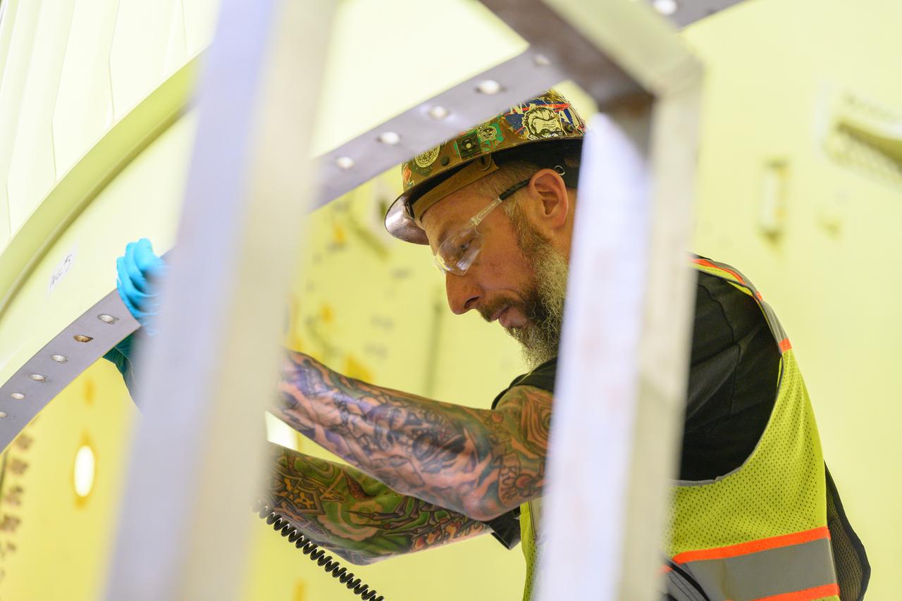
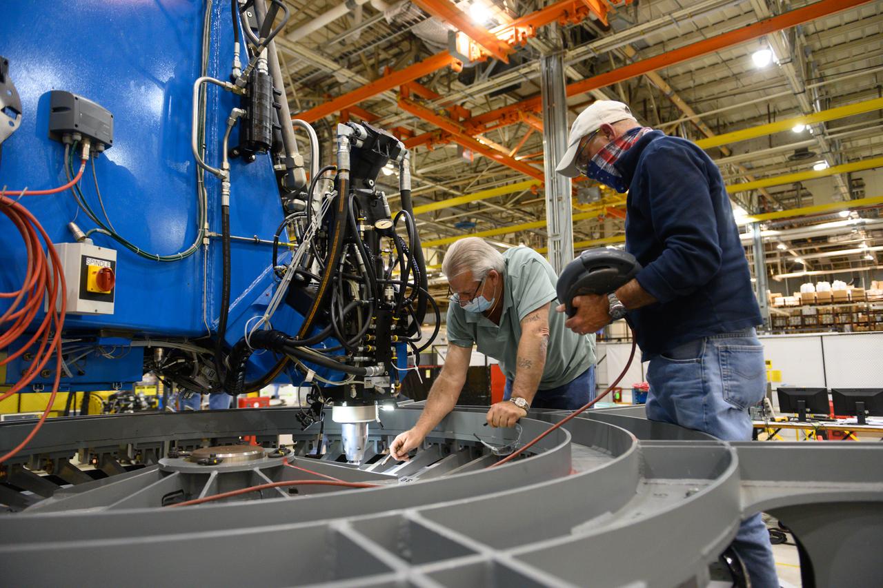
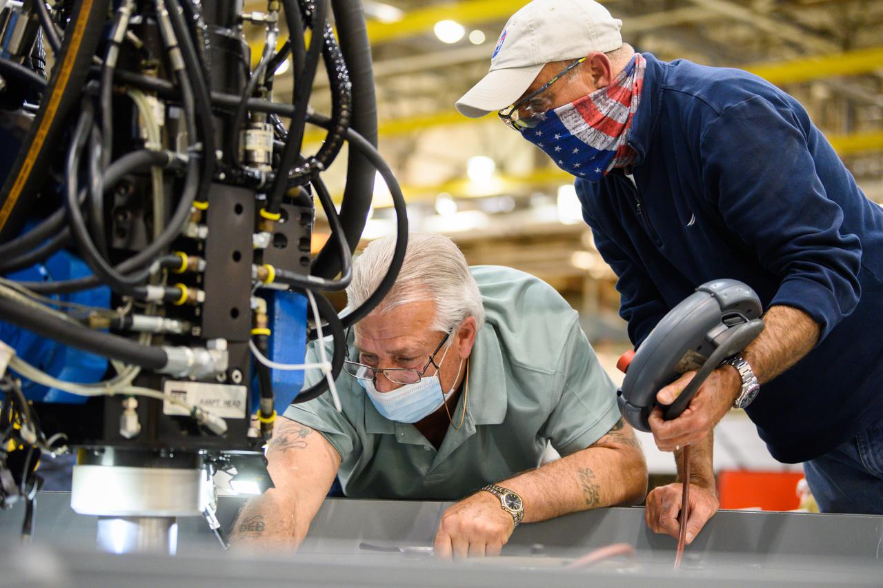
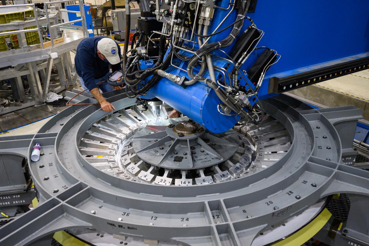
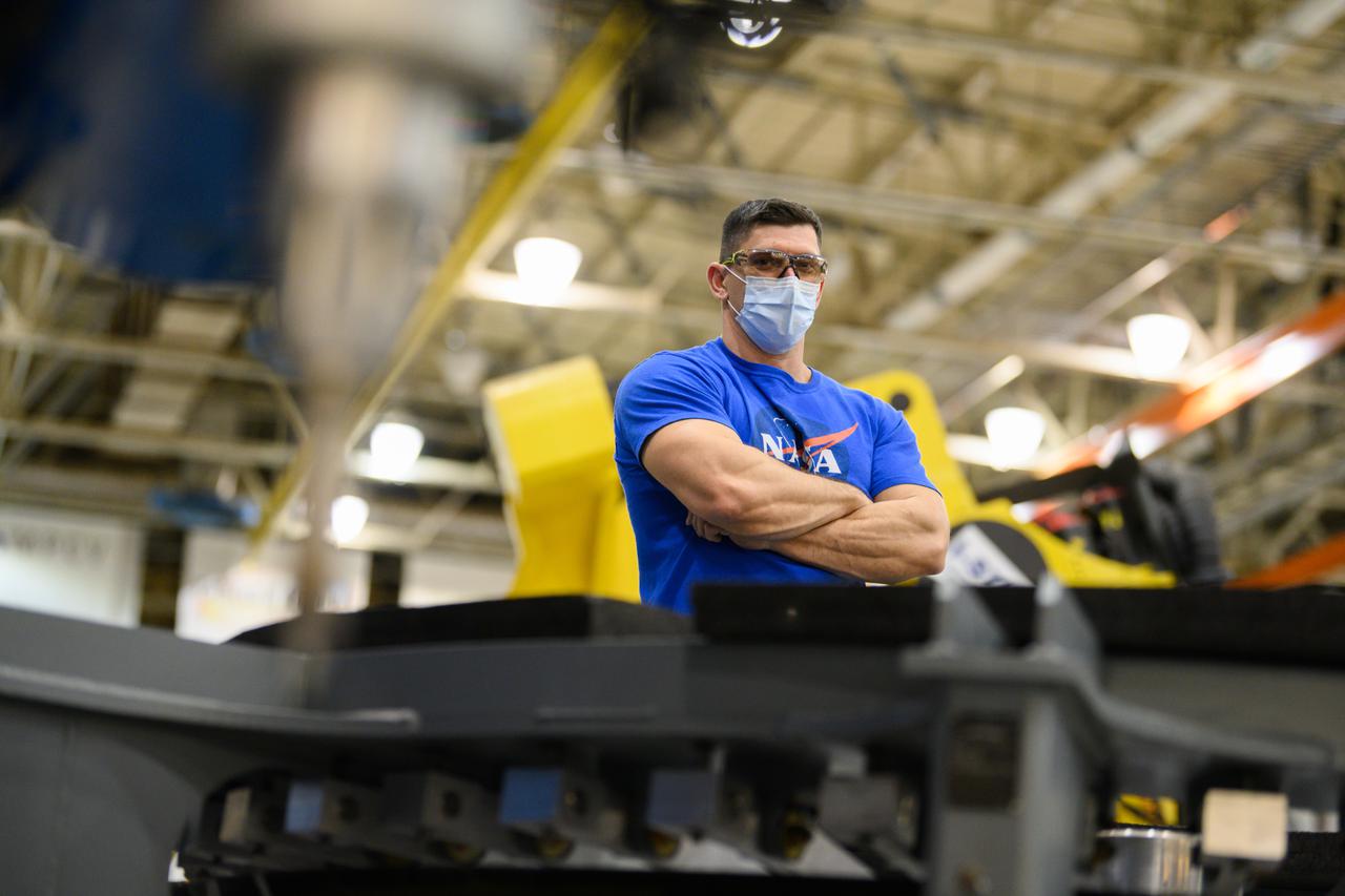
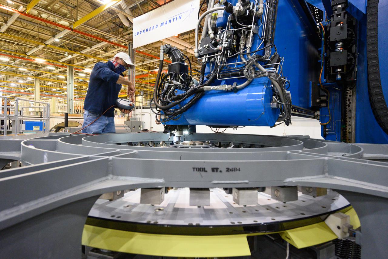
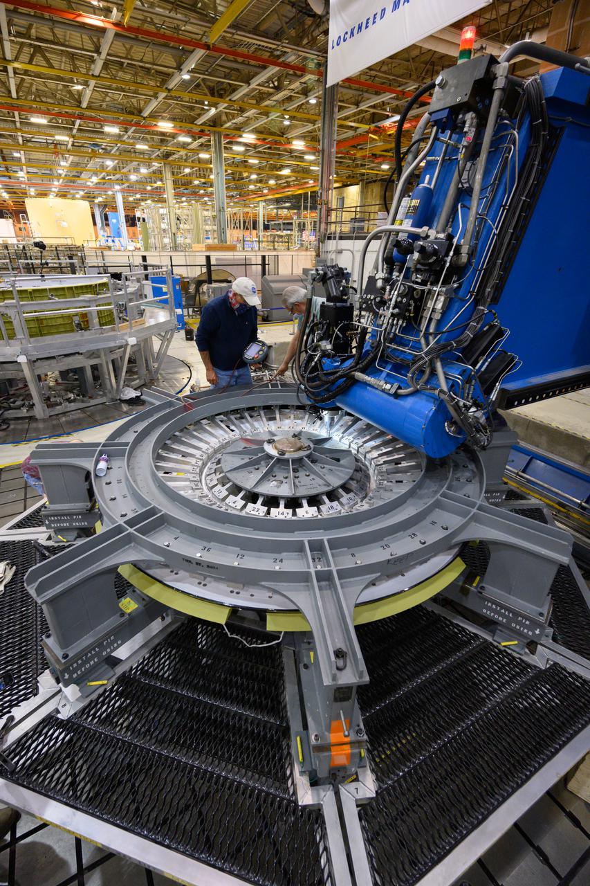
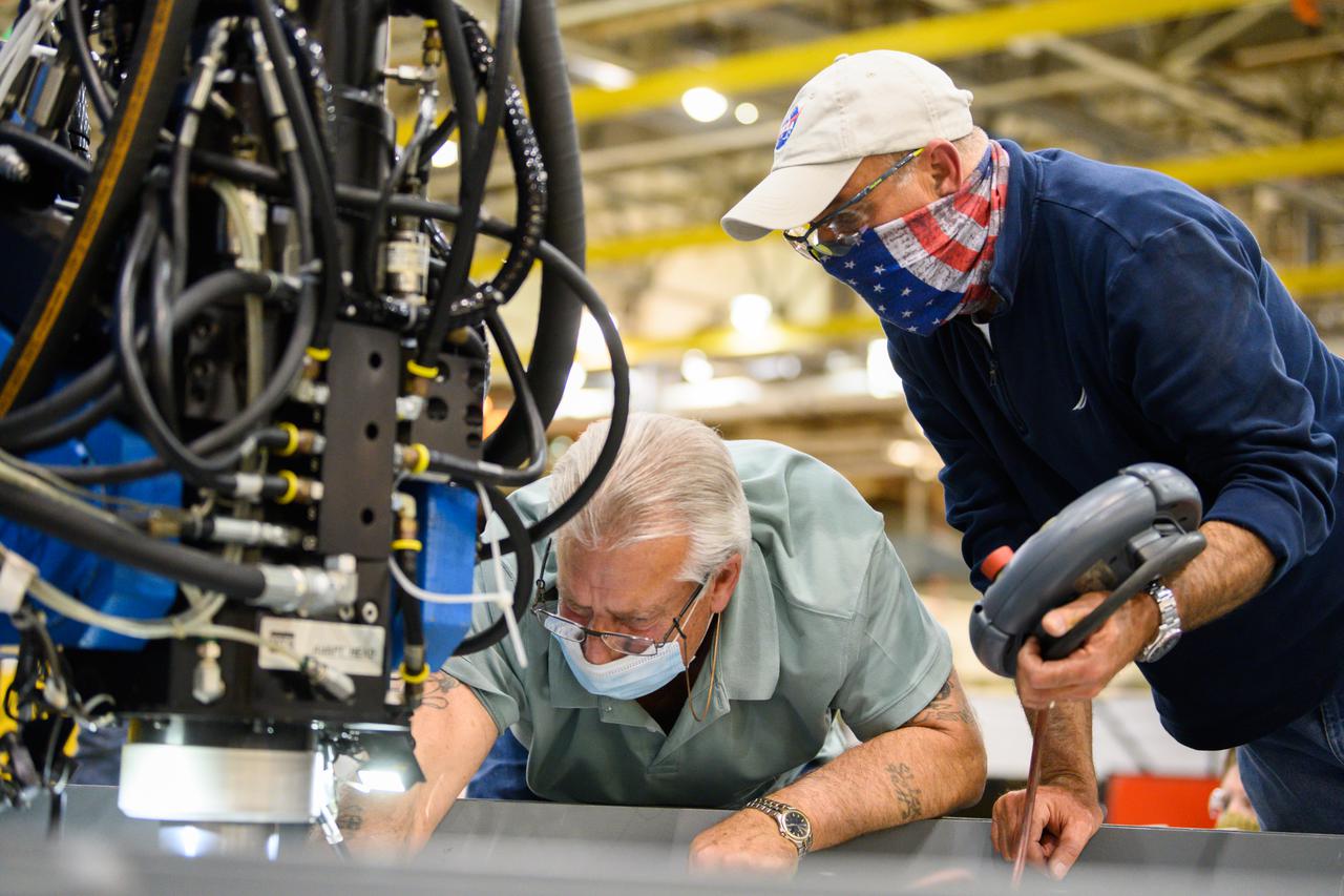
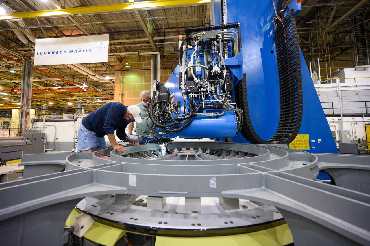
Technicians from Orion Prime Contractor Lockheed Martin weld the forward bulkhead of the pressure vessel to the tunnel hardware on the Orion Spacecraft for the Artemis III mission at NASA’s Michoud Assembly Facility in New Orleans. The crew module’s primary structure, the pressure vessel, is comprised of seven machined aluminum alloy pieces that are welded together through a weld process that produces a strong, air-tight habitable space for astronauts during the mission. The pressure vessel is designed to withstand the harsh and demanding environment of deep space and is the core structure upon which all the other elements of Orion’s crew module are integrated. This pressure vessel weld is the next step following the completion of the crew module cone panel welds and creates the top of the spacecraft. Work will then begin to join the barrel with the aft bulkhead to form the bottom of Orion. Last, the forward bulkhead will be welded to the top of the panels and, for the seventh and closeout weld, the bottom of the cone panels will be joined to the barrel to complete the pressure vessel. Once welding of the Artemis III crew module primary structure is complete, it will be shipped to NASA’s Kennedy Space Center in Florida where it will undergo further assembly beginning this fall. Orion, the Space Launch System, and Exploration Ground Systems programs are foundational elements of the Artemis program. Artemis I will be the first integrated flight test of Orion and SLS and is targeted to launch later this year. Artemis II will follow and is the first crewed mission, taking humans farther into space than ever before.

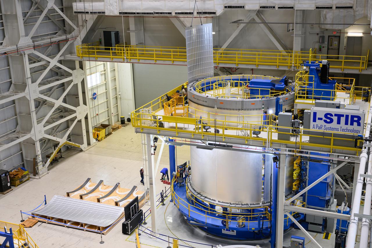
Crews at NASA’s Michoud Assembly Facility in New Orleans load alluminum alloy panels into the Vertical Weld Center June 1. The Vertical Weld Center is a friction-stir weld tool for the large structures of the core stage for the SLS (Space Launch System) rocket. Teams load the panels into the VWC using an overhead crane system, then multiple panels are welded together to create entire barrels. The panels in these images are some of the five barrels that will form the SLS liquid hydrogen propellant tank for the SLS rocket that will power NASA’s Artemis IV mission, which is also the first flight of SLS in its more powerful Block 1B configuration. The SLS core stage is made up of five unique elements: the forward skirt, liquid oxygen tank, intertank, liquid hydrogen tank, and the engine section. The liquid hydrogen propellant tank holds 537,000 gallons of liquid hydrogen cooled to minus 432 degrees Fahrenheit and sits between the core stage’s intertank and engine section. The liquid hydrogen hardware, along with the liquid oxygen tank, provides propellant to the four RS-25 engines at the bottom of the core stage to produce more than two million pounds of thrust to help launch the Artemis IV mission to the Moon. Together with its four RS-25 engines, the rocket’s massive 212-foot-tall core stage — the largest stage NASA has ever built — and its twin solid rocket boosters produce 8.8 million pounds of thrust to send NASA’s Orion spacecraft, astronauts and supplies beyond Earth’s orbit to the Moon. NASA is working to land the first woman and first person of color on the Moon under Artemis. SLS is part of NASA’s backbone for deep space exploration, along with Orion and the Gateway in orbit around the Moon. SLS is the only rocket that can send Orion, astronauts, and supplies to the Moon in a single mission.
Technicians from Orion Prime Contractor Lockheed Martin weld the forward bulkhead of the pressure vessel to the tunnel hardware on the Orion Spacecraft for the Artemis III mission at NASA’s Michoud Assembly Facility in New Orleans. The crew module’s primary structure, the pressure vessel, is comprised of seven machined aluminum alloy pieces that are welded together through a weld process that produces a strong, air-tight habitable space for astronauts during the mission. The pressure vessel is designed to withstand the harsh and demanding environment of deep space and is the core structure upon which all the other elements of Orion’s crew module are integrated. This pressure vessel weld is the next step following the completion of the crew module cone panel welds and creates the top of the spacecraft. Work will then begin to join the barrel with the aft bulkhead to form the bottom of Orion. Last, the forward bulkhead will be welded to the top of the panels and, for the seventh and closeout weld, the bottom of the cone panels will be joined to the barrel to complete the pressure vessel. Once welding of the Artemis III crew module primary structure is complete, it will be shipped to NASA’s Kennedy Space Center in Florida where it will undergo further assembly beginning this fall. Orion, the Space Launch System, and Exploration Ground Systems programs are foundational elements of the Artemis program. Artemis I will be the first integrated flight test of Orion and SLS and is targeted to launch later this year. Artemis II will follow and is the first crewed mission, taking humans farther into space than ever before.
Technicians from Orion Prime Contractor Lockheed Martin weld the forward bulkhead of the pressure vessel to the tunnel hardware on the Orion Spacecraft for the Artemis III mission at NASA’s Michoud Assembly Facility in New Orleans. The crew module’s primary structure, the pressure vessel, is comprised of seven machined aluminum alloy pieces that are welded together through a weld process that produces a strong, air-tight habitable space for astronauts during the mission. The pressure vessel is designed to withstand the harsh and demanding environment of deep space and is the core structure upon which all the other elements of Orion’s crew module are integrated. This pressure vessel weld is the next step following the completion of the crew module cone panel welds and creates the top of the spacecraft. Work will then begin to join the barrel with the aft bulkhead to form the bottom of Orion. Last, the forward bulkhead will be welded to the top of the panels and, for the seventh and closeout weld, the bottom of the cone panels will be joined to the barrel to complete the pressure vessel. Once welding of the Artemis III crew module primary structure is complete, it will be shipped to NASA’s Kennedy Space Center in Florida where it will undergo further assembly beginning this fall. Orion, the Space Launch System, and Exploration Ground Systems programs are foundational elements of the Artemis program. Artemis I will be the first integrated flight test of Orion and SLS and is targeted to launch later this year. Artemis II will follow and is the first crewed mission, taking humans farther into space than ever before.
Technicians from Orion Prime Contractor Lockheed Martin weld the forward bulkhead of the pressure vessel to the tunnel hardware on the Orion Spacecraft for the Artemis III mission at NASA’s Michoud Assembly Facility in New Orleans. The crew module’s primary structure, the pressure vessel, is comprised of seven machined aluminum alloy pieces that are welded together through a weld process that produces a strong, air-tight habitable space for astronauts during the mission. The pressure vessel is designed to withstand the harsh and demanding environment of deep space and is the core structure upon which all the other elements of Orion’s crew module are integrated. This pressure vessel weld is the next step following the completion of the crew module cone panel welds and creates the top of the spacecraft. Work will then begin to join the barrel with the aft bulkhead to form the bottom of Orion. Last, the forward bulkhead will be welded to the top of the panels and, for the seventh and closeout weld, the bottom of the cone panels will be joined to the barrel to complete the pressure vessel. Once welding of the Artemis III crew module primary structure is complete, it will be shipped to NASA’s Kennedy Space Center in Florida where it will undergo further assembly beginning this fall. Orion, the Space Launch System, and Exploration Ground Systems programs are foundational elements of the Artemis program. Artemis I will be the first integrated flight test of Orion and SLS and is targeted to launch later this year. Artemis II will follow and is the first crewed mission, taking humans farther into space than ever before.
Technicians from Orion Prime Contractor Lockheed Martin weld the forward bulkhead of the pressure vessel to the tunnel hardware on the Orion Spacecraft for the Artemis III mission at NASA’s Michoud Assembly Facility in New Orleans. The crew module’s primary structure, the pressure vessel, is comprised of seven machined aluminum alloy pieces that are welded together through a weld process that produces a strong, air-tight habitable space for astronauts during the mission. The pressure vessel is designed to withstand the harsh and demanding environment of deep space and is the core structure upon which all the other elements of Orion’s crew module are integrated. This pressure vessel weld is the next step following the completion of the crew module cone panel welds and creates the top of the spacecraft. Work will then begin to join the barrel with the aft bulkhead to form the bottom of Orion. Last, the forward bulkhead will be welded to the top of the panels and, for the seventh and closeout weld, the bottom of the cone panels will be joined to the barrel to complete the pressure vessel. Once welding of the Artemis III crew module primary structure is complete, it will be shipped to NASA’s Kennedy Space Center in Florida where it will undergo further assembly beginning this fall. Orion, the Space Launch System, and Exploration Ground Systems programs are foundational elements of the Artemis program. Artemis I will be the first integrated flight test of Orion and SLS and is targeted to launch later this year. Artemis II will follow and is the first crewed mission, taking humans farther into space than ever before.
Technicians from Orion Prime Contractor Lockheed Martin weld the forward bulkhead of the pressure vessel to the tunnel hardware on the Orion Spacecraft for the Artemis III mission at NASA’s Michoud Assembly Facility in New Orleans. The crew module’s primary structure, the pressure vessel, is comprised of seven machined aluminum alloy pieces that are welded together through a weld process that produces a strong, air-tight habitable space for astronauts during the mission. The pressure vessel is designed to withstand the harsh and demanding environment of deep space and is the core structure upon which all the other elements of Orion’s crew module are integrated. This pressure vessel weld is the next step following the completion of the crew module cone panel welds and creates the top of the spacecraft. Work will then begin to join the barrel with the aft bulkhead to form the bottom of Orion. Last, the forward bulkhead will be welded to the top of the panels and, for the seventh and closeout weld, the bottom of the cone panels will be joined to the barrel to complete the pressure vessel. Once welding of the Artemis III crew module primary structure is complete, it will be shipped to NASA’s Kennedy Space Center in Florida where it will undergo further assembly beginning this fall. Orion, the Space Launch System, and Exploration Ground Systems programs are foundational elements of the Artemis program. Artemis I will be the first integrated flight test of Orion and SLS and is targeted to launch later this year. Artemis II will follow and is the first crewed mission, taking humans farther into space than ever before.
Technicians from Orion Prime Contractor Lockheed Martin weld the forward bulkhead of the pressure vessel to the tunnel hardware on the Orion Spacecraft for the Artemis III mission at NASA’s Michoud Assembly Facility in New Orleans. The crew module’s primary structure, the pressure vessel, is comprised of seven machined aluminum alloy pieces that are welded together through a weld process that produces a strong, air-tight habitable space for astronauts during the mission. The pressure vessel is designed to withstand the harsh and demanding environment of deep space and is the core structure upon which all the other elements of Orion’s crew module are integrated. This pressure vessel weld is the next step following the completion of the crew module cone panel welds and creates the top of the spacecraft. Work will then begin to join the barrel with the aft bulkhead to form the bottom of Orion. Last, the forward bulkhead will be welded to the top of the panels and, for the seventh and closeout weld, the bottom of the cone panels will be joined to the barrel to complete the pressure vessel. Once welding of the Artemis III crew module primary structure is complete, it will be shipped to NASA’s Kennedy Space Center in Florida where it will undergo further assembly beginning this fall. Orion, the Space Launch System, and Exploration Ground Systems programs are foundational elements of the Artemis program. Artemis I will be the first integrated flight test of Orion and SLS and is targeted to launch later this year. Artemis II will follow and is the first crewed mission, taking humans farther into space than ever before.
Technicians from Orion Prime Contractor Lockheed Martin weld the forward bulkhead of the pressure vessel to the tunnel hardware on the Orion Spacecraft for the Artemis III mission at NASA’s Michoud Assembly Facility in New Orleans. The crew module’s primary structure, the pressure vessel, is comprised of seven machined aluminum alloy pieces that are welded together through a weld process that produces a strong, air-tight habitable space for astronauts during the mission. The pressure vessel is designed to withstand the harsh and demanding environment of deep space and is the core structure upon which all the other elements of Orion’s crew module are integrated. This pressure vessel weld is the next step following the completion of the crew module cone panel welds and creates the top of the spacecraft. Work will then begin to join the barrel with the aft bulkhead to form the bottom of Orion. Last, the forward bulkhead will be welded to the top of the panels and, for the seventh and closeout weld, the bottom of the cone panels will be joined to the barrel to complete the pressure vessel. Once welding of the Artemis III crew module primary structure is complete, it will be shipped to NASA’s Kennedy Space Center in Florida where it will undergo further assembly beginning this fall. Orion, the Space Launch System, and Exploration Ground Systems programs are foundational elements of the Artemis program. Artemis I will be the first integrated flight test of Orion and SLS and is targeted to launch later this year. Artemis II will follow and is the first crewed mission, taking humans farther into space than ever before.

Technicians from Orion Prime Contractor Lockheed Martin weld the forward bulkhead of the pressure vessel to the tunnel hardware on the Orion Spacecraft for the Artemis III mission at NASA’s Michoud Assembly Facility in New Orleans. The crew module’s primary structure, the pressure vessel, is comprised of seven machined aluminum alloy pieces that are welded together through a weld process that produces a strong, air-tight habitable space for astronauts during the mission. The pressure vessel is designed to withstand the harsh and demanding environment of deep space and is the core structure upon which all the other elements of Orion’s crew module are integrated. This pressure vessel weld is the next step following the completion of the crew module cone panel welds and creates the top of the spacecraft. Work will then begin to join the barrel with the aft bulkhead to form the bottom of Orion. Last, the forward bulkhead will be welded to the top of the panels and, for the seventh and closeout weld, the bottom of the cone panels will be joined to the barrel to complete the pressure vessel. Once welding of the Artemis III crew module primary structure is complete, it will be shipped to NASA’s Kennedy Space Center in Florida where it will undergo further assembly beginning this fall. Orion, the Space Launch System, and Exploration Ground Systems programs are foundational elements of the Artemis program. Artemis I will be the first integrated flight test of Orion and SLS and is targeted to launch later this year. Artemis II will follow and is the first crewed mission, taking humans farther into space than ever before.
Crews at NASA’s Michoud Assembly Facility in New Orleans load alluminum alloy panels into the Vertical Weld Center June 1. The Vertical Weld Center is a friction-stir weld tool for the large structures of the core stage for the SLS (Space Launch System) rocket. Teams load the panels into the VWC using an overhead crane system, then multiple panels are welded together to create entire barrels. The panels in these images are some of the five barrels that will form the SLS liquid hydrogen propellant tank for the SLS rocket that will power NASA’s Artemis IV mission, which is also the first flight of SLS in its more powerful Block 1B configuration. The SLS core stage is made up of five unique elements: the forward skirt, liquid oxygen tank, intertank, liquid hydrogen tank, and the engine section. The liquid hydrogen propellant tank holds 537,000 gallons of liquid hydrogen cooled to minus 432 degrees Fahrenheit and sits between the core stage’s intertank and engine section. The liquid hydrogen hardware, along with the liquid oxygen tank, provides propellant to the four RS-25 engines at the bottom of the core stage to produce more than two million pounds of thrust to help launch the Artemis IV mission to the Moon. Together with its four RS-25 engines, the rocket’s massive 212-foot-tall core stage — the largest stage NASA has ever built — and its twin solid rocket boosters produce 8.8 million pounds of thrust to send NASA’s Orion spacecraft, astronauts and supplies beyond Earth’s orbit to the Moon. NASA is working to land the first woman and first person of color on the Moon under Artemis. SLS is part of NASA’s backbone for deep space exploration, along with Orion and the Gateway in orbit around the Moon. SLS is the only rocket that can send Orion, astronauts, and supplies to the Moon in a single mission.
Technicians from Orion Prime Contractor Lockheed Martin weld the forward bulkhead of the pressure vessel to the tunnel hardware on the Orion Spacecraft for the Artemis III mission at NASA’s Michoud Assembly Facility in New Orleans. The crew module’s primary structure, the pressure vessel, is comprised of seven machined aluminum alloy pieces that are welded together through a weld process that produces a strong, air-tight habitable space for astronauts during the mission. The pressure vessel is designed to withstand the harsh and demanding environment of deep space and is the core structure upon which all the other elements of Orion’s crew module are integrated. This pressure vessel weld is the next step following the completion of the crew module cone panel welds and creates the top of the spacecraft. Work will then begin to join the barrel with the aft bulkhead to form the bottom of Orion. Last, the forward bulkhead will be welded to the top of the panels and, for the seventh and closeout weld, the bottom of the cone panels will be joined to the barrel to complete the pressure vessel. Once welding of the Artemis III crew module primary structure is complete, it will be shipped to NASA’s Kennedy Space Center in Florida where it will undergo further assembly beginning this fall. Orion, the Space Launch System, and Exploration Ground Systems programs are foundational elements of the Artemis program. Artemis I will be the first integrated flight test of Orion and SLS and is targeted to launch later this year. Artemis II will follow and is the first crewed mission, taking humans farther into space than ever before.
Technicians from Orion Prime Contractor Lockheed Martin weld the forward bulkhead of the pressure vessel to the tunnel hardware on the Orion Spacecraft for the Artemis III mission at NASA’s Michoud Assembly Facility in New Orleans. The crew module’s primary structure, the pressure vessel, is comprised of seven machined aluminum alloy pieces that are welded together through a weld process that produces a strong, air-tight habitable space for astronauts during the mission. The pressure vessel is designed to withstand the harsh and demanding environment of deep space and is the core structure upon which all the other elements of Orion’s crew module are integrated. This pressure vessel weld is the next step following the completion of the crew module cone panel welds and creates the top of the spacecraft. Work will then begin to join the barrel with the aft bulkhead to form the bottom of Orion. Last, the forward bulkhead will be welded to the top of the panels and, for the seventh and closeout weld, the bottom of the cone panels will be joined to the barrel to complete the pressure vessel. Once welding of the Artemis III crew module primary structure is complete, it will be shipped to NASA’s Kennedy Space Center in Florida where it will undergo further assembly beginning this fall. Orion, the Space Launch System, and Exploration Ground Systems programs are foundational elements of the Artemis program. Artemis I will be the first integrated flight test of Orion and SLS and is targeted to launch later this year. Artemis II will follow and is the first crewed mission, taking humans farther into space than ever before.
Technicians from Orion Prime Contractor Lockheed Martin weld the forward bulkhead of the pressure vessel to the tunnel hardware on the Orion Spacecraft for the Artemis III mission at NASA’s Michoud Assembly Facility in New Orleans. The crew module’s primary structure, the pressure vessel, is comprised of seven machined aluminum alloy pieces that are welded together through a weld process that produces a strong, air-tight habitable space for astronauts during the mission. The pressure vessel is designed to withstand the harsh and demanding environment of deep space and is the core structure upon which all the other elements of Orion’s crew module are integrated. This pressure vessel weld is the next step following the completion of the crew module cone panel welds and creates the top of the spacecraft. Work will then begin to join the barrel with the aft bulkhead to form the bottom of Orion. Last, the forward bulkhead will be welded to the top of the panels and, for the seventh and closeout weld, the bottom of the cone panels will be joined to the barrel to complete the pressure vessel. Once welding of the Artemis III crew module primary structure is complete, it will be shipped to NASA’s Kennedy Space Center in Florida where it will undergo further assembly beginning this fall. Orion, the Space Launch System, and Exploration Ground Systems programs are foundational elements of the Artemis program. Artemis I will be the first integrated flight test of Orion and SLS and is targeted to launch later this year. Artemis II will follow and is the first crewed mission, taking humans farther into space than ever before.
Technicians from Orion Prime Contractor Lockheed Martin weld the forward bulkhead of the pressure vessel to the tunnel hardware on the Orion Spacecraft for the Artemis III mission at NASA’s Michoud Assembly Facility in New Orleans. The crew module’s primary structure, the pressure vessel, is comprised of seven machined aluminum alloy pieces that are welded together through a weld process that produces a strong, air-tight habitable space for astronauts during the mission. The pressure vessel is designed to withstand the harsh and demanding environment of deep space and is the core structure upon which all the other elements of Orion’s crew module are integrated. This pressure vessel weld is the next step following the completion of the crew module cone panel welds and creates the top of the spacecraft. Work will then begin to join the barrel with the aft bulkhead to form the bottom of Orion. Last, the forward bulkhead will be welded to the top of the panels and, for the seventh and closeout weld, the bottom of the cone panels will be joined to the barrel to complete the pressure vessel. Once welding of the Artemis III crew module primary structure is complete, it will be shipped to NASA’s Kennedy Space Center in Florida where it will undergo further assembly beginning this fall. Orion, the Space Launch System, and Exploration Ground Systems programs are foundational elements of the Artemis program. Artemis I will be the first integrated flight test of Orion and SLS and is targeted to launch later this year. Artemis II will follow and is the first crewed mission, taking humans farther into space than ever before.
Technicians from Orion Prime Contractor Lockheed Martin weld the forward bulkhead of the pressure vessel to the tunnel hardware on the Orion Spacecraft for the Artemis III mission at NASA’s Michoud Assembly Facility in New Orleans. The crew module’s primary structure, the pressure vessel, is comprised of seven machined aluminum alloy pieces that are welded together through a weld process that produces a strong, air-tight habitable space for astronauts during the mission. The pressure vessel is designed to withstand the harsh and demanding environment of deep space and is the core structure upon which all the other elements of Orion’s crew module are integrated. This pressure vessel weld is the next step following the completion of the crew module cone panel welds and creates the top of the spacecraft. Work will then begin to join the barrel with the aft bulkhead to form the bottom of Orion. Last, the forward bulkhead will be welded to the top of the panels and, for the seventh and closeout weld, the bottom of the cone panels will be joined to the barrel to complete the pressure vessel. Once welding of the Artemis III crew module primary structure is complete, it will be shipped to NASA’s Kennedy Space Center in Florida where it will undergo further assembly beginning this fall. Orion, the Space Launch System, and Exploration Ground Systems programs are foundational elements of the Artemis program. Artemis I will be the first integrated flight test of Orion and SLS and is targeted to launch later this year. Artemis II will follow and is the first crewed mission, taking humans farther into space than ever before.