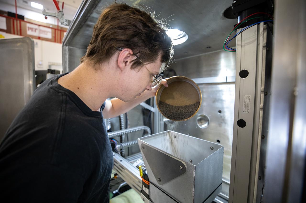
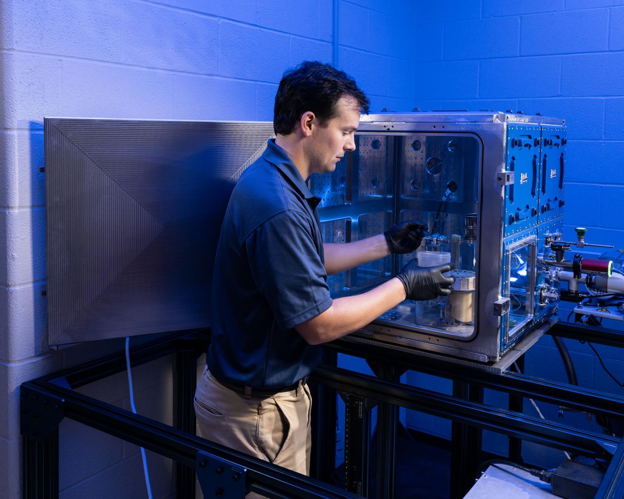
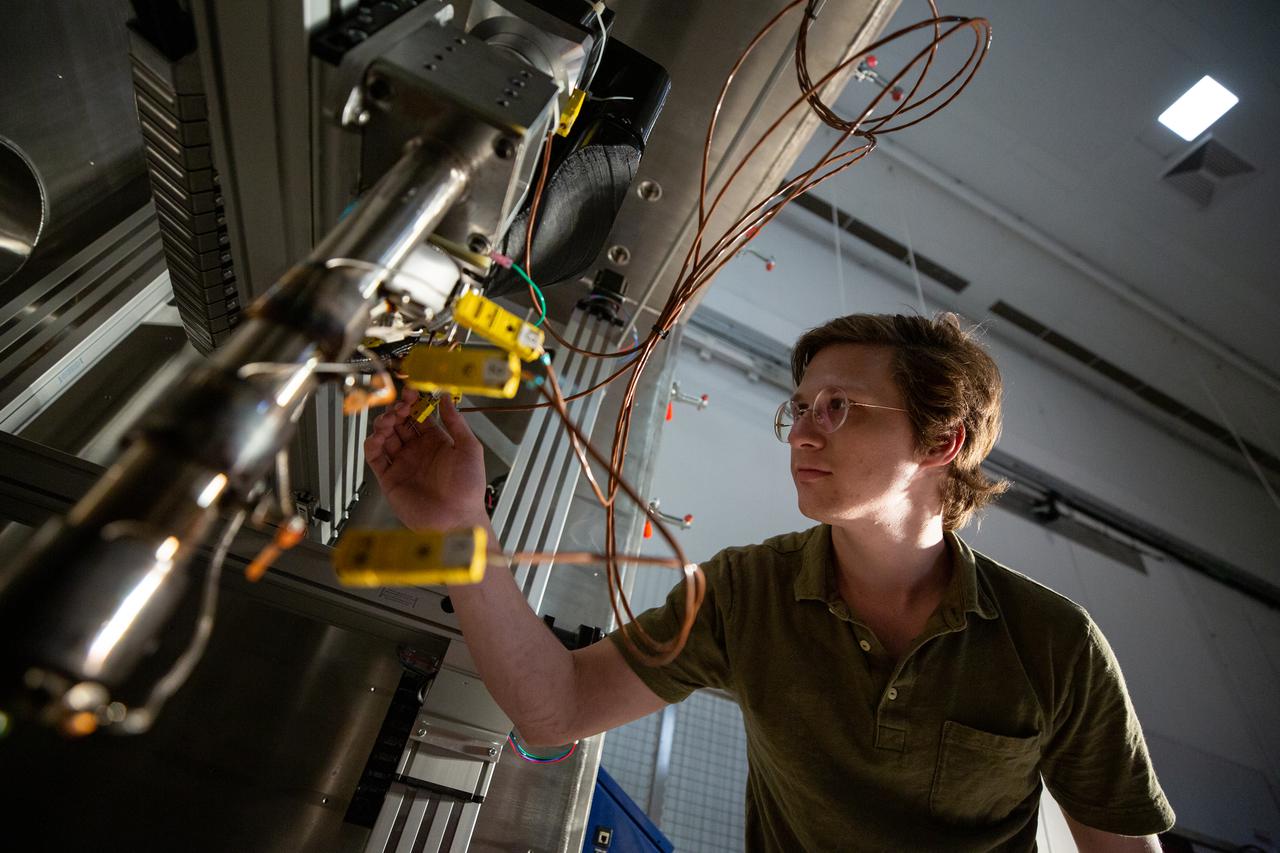
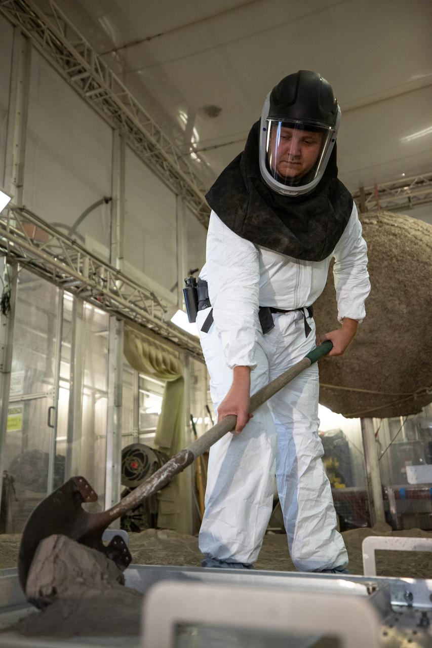
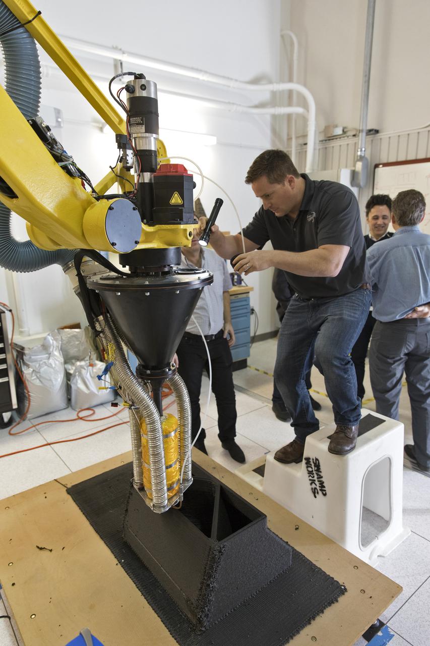
Materials engineer Thomas Lipscomb tests a 3D printer on July 28, 2022, at Swamp Works at NASA’s Kennedy Space Center in Florida, as part of the Relevant Environment Additive Construction Technology (REACT) project. Among the key objectives of the project is developing an architectural and structural design for a shelter that provides protection to habitable assets on the lunar surface. Testing REACT derives from NASA’s 2020 Announcement of Collaboration Opportunity with AI SpaceFactory – an architectural and construction technology company and winner of NASA’s 3D Printed Habitat Challenge.
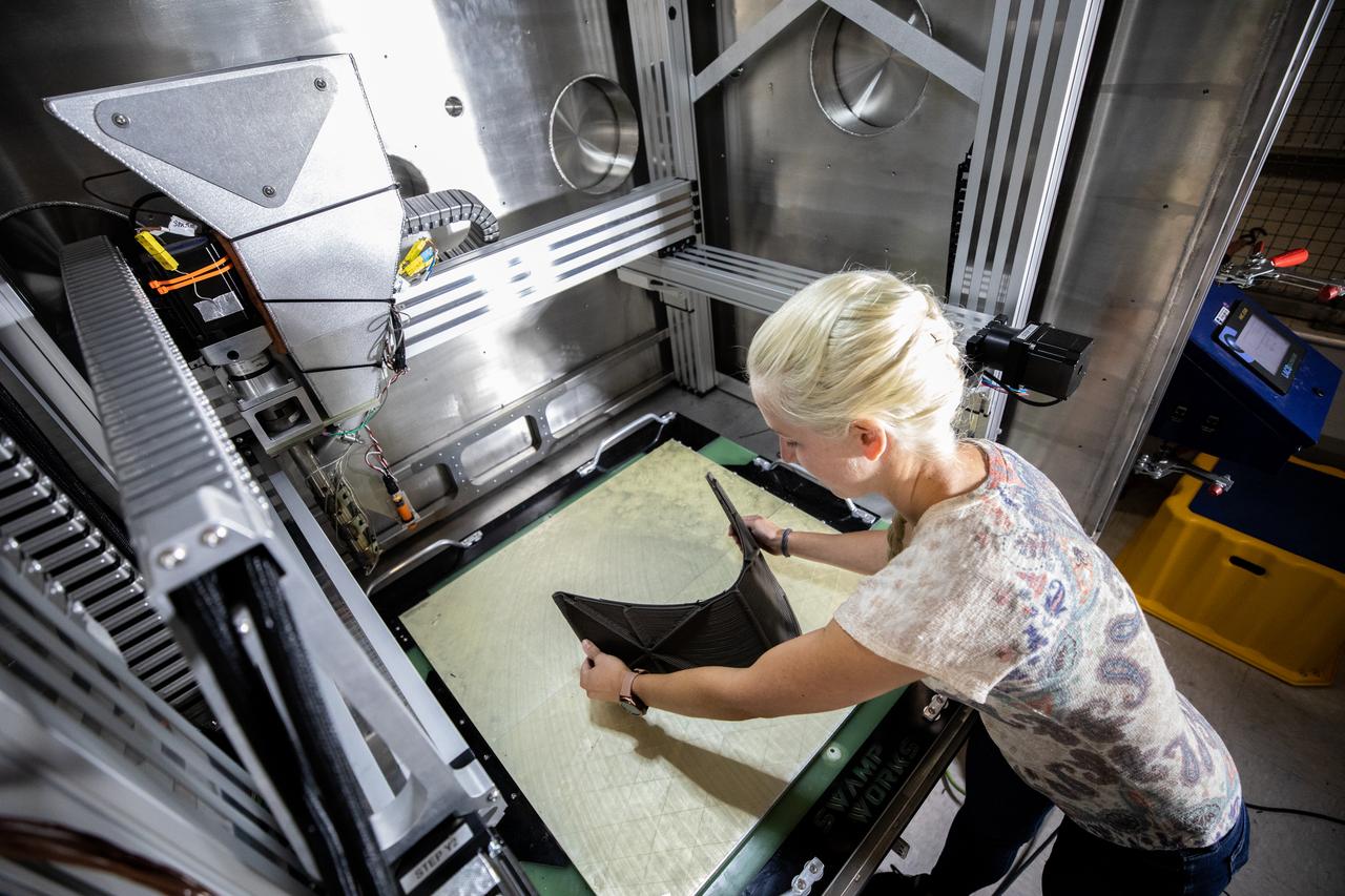
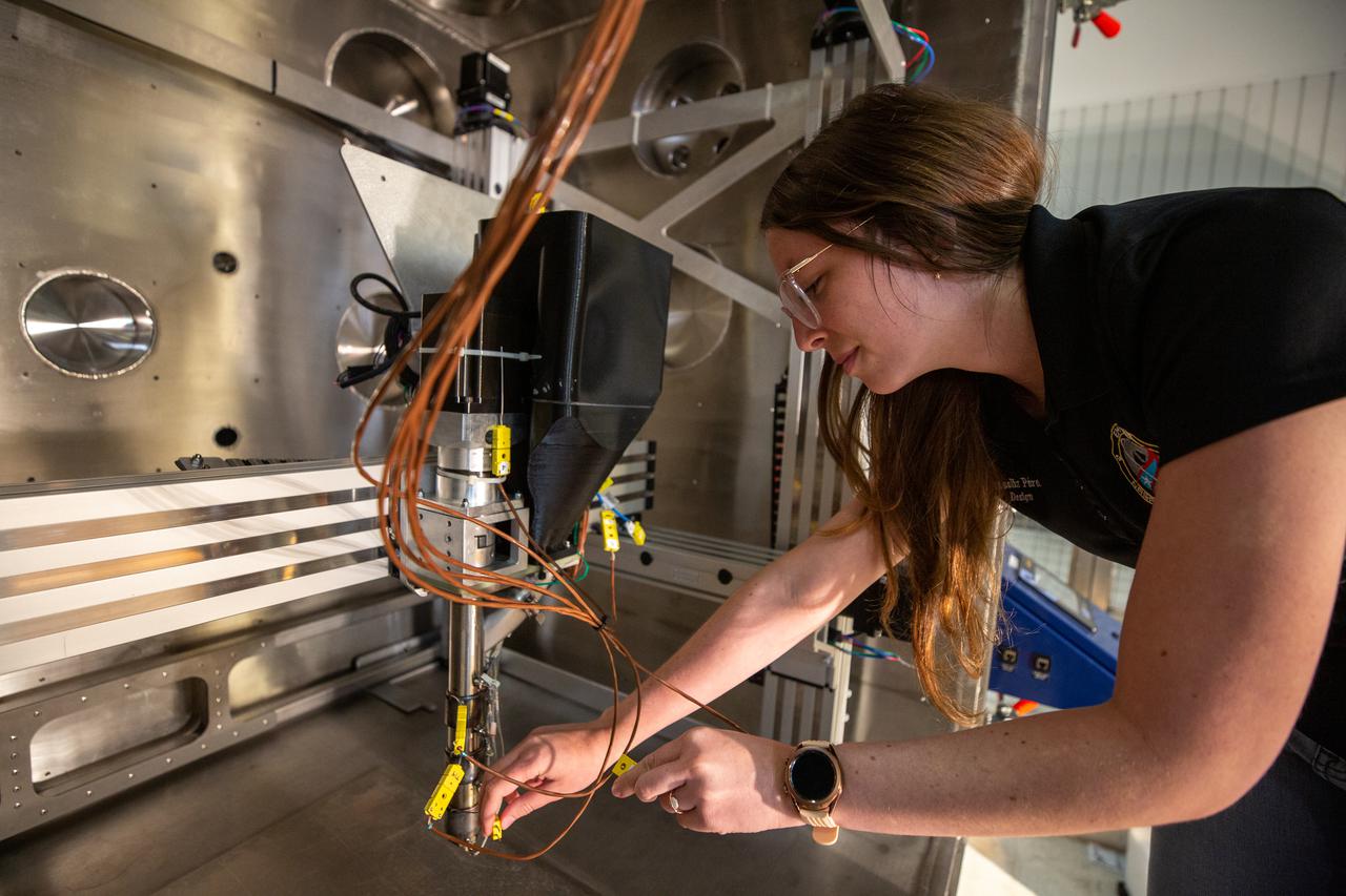
Chemist Tesia Irwin tests a 3D printer on July 28, 2022, at Swamp Works at NASA’s Kennedy Space Center in Florida, as part of the Relevant Environment Additive Construction Technology (REACT) project. Among the key objectives of the project is developing an architectural and structural design for a shelter that provides protection to habitable assets on the lunar surface. Testing REACT derives from NASA’s 2020 Announcement of Collaboration Opportunity with AI SpaceFactory – an architectural and construction technology company and winner of NASA’s 3D Printed Habitat Challenge.
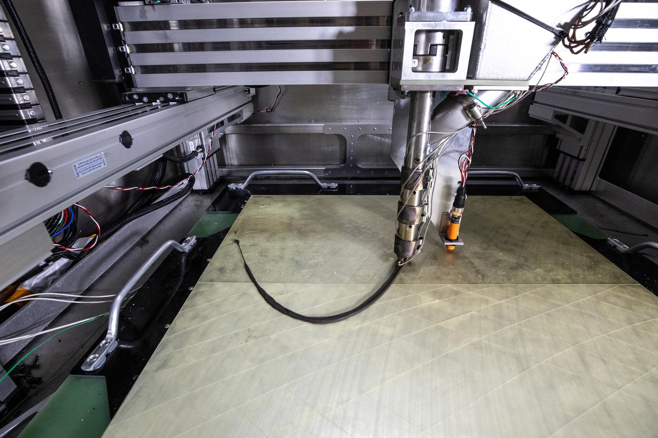
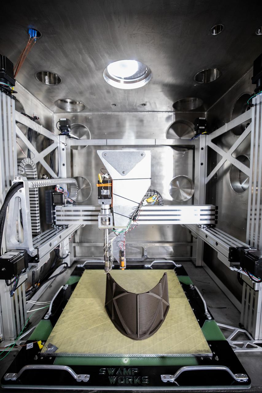
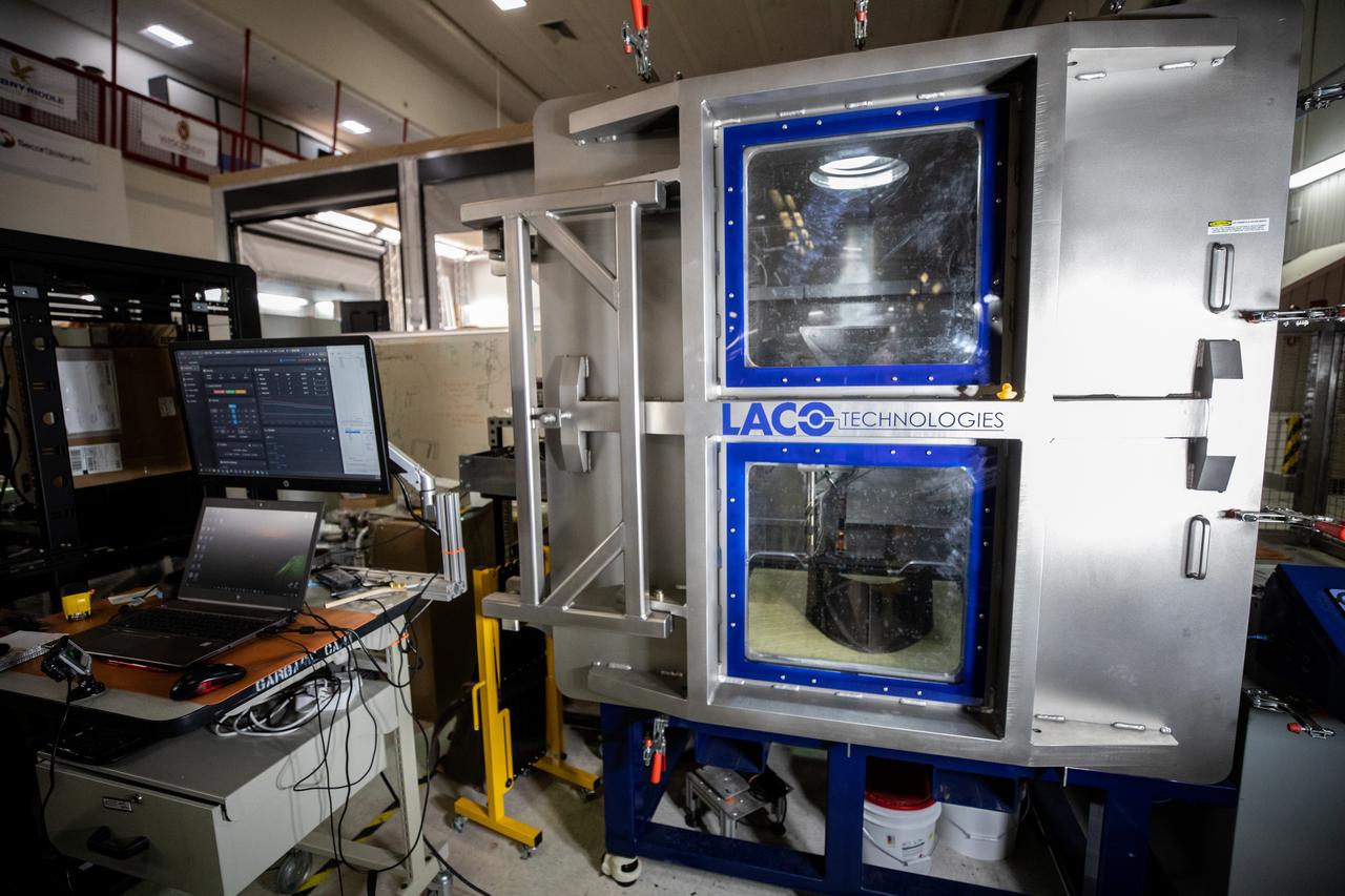
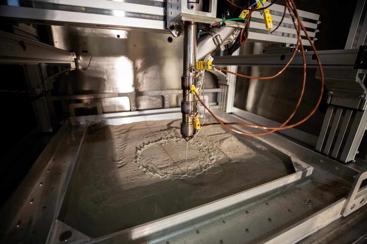
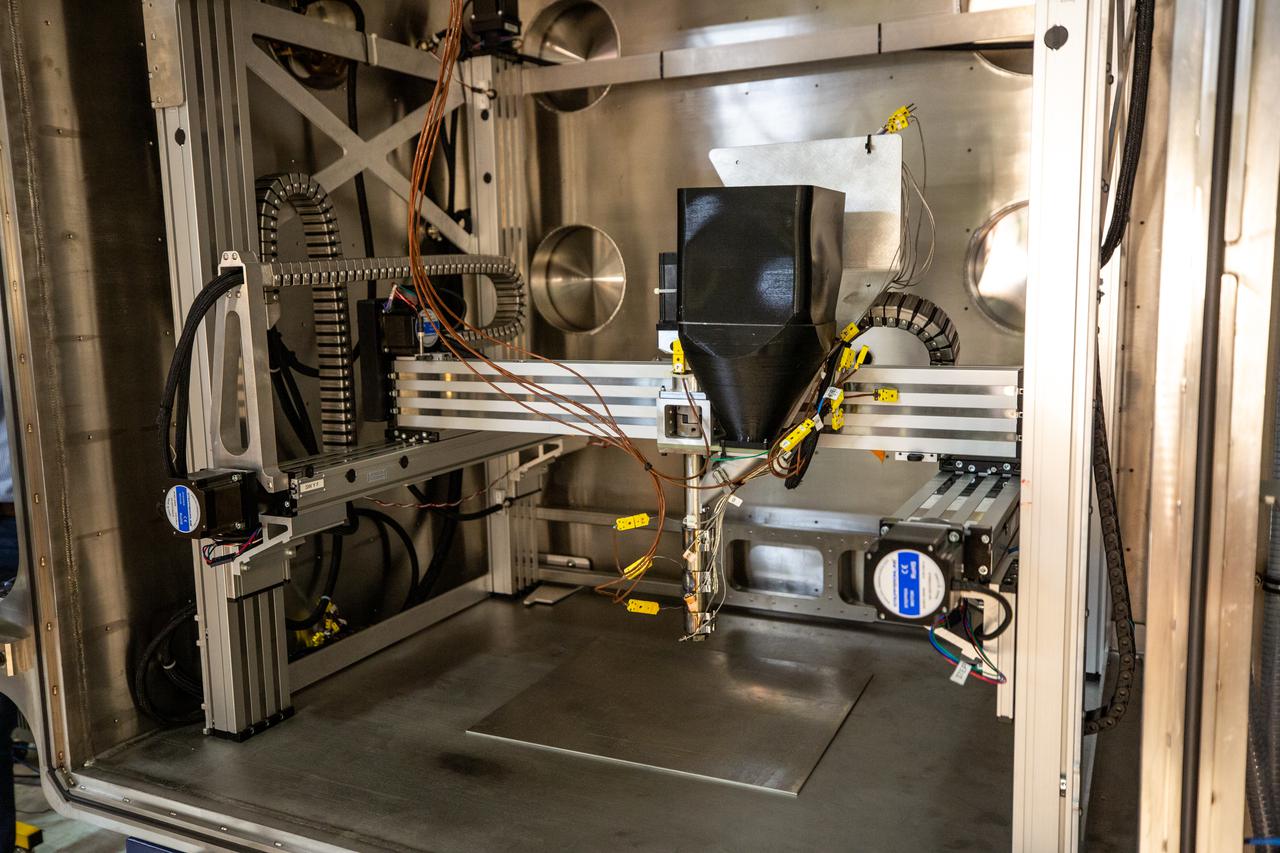
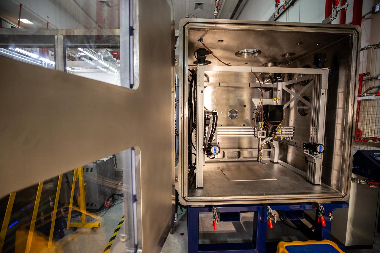
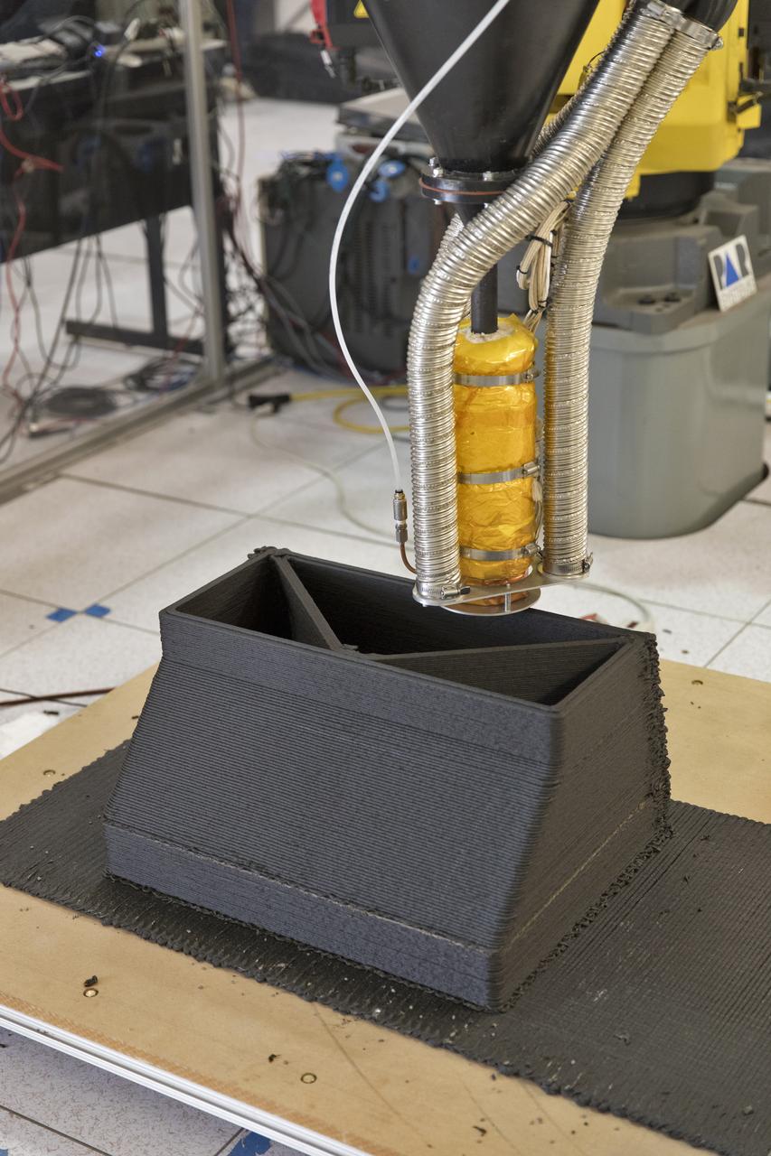
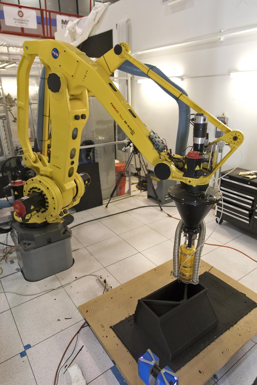
Shown is a Zero Launch Mass 3D printer on July 28, 2022, at NASA’s Kennedy Space Center’s Swamp Works. A team at the Florida spaceport tested the printer as part of the Relevant Environment Additive Construction Technology (REACT) project. Among the key objectives of the project is developing an architectural and structural design for a shelter that provides protection to habitable assets on the lunar surface. Testing REACT derives from NASA’s 2020 Announcement of Collaboration Opportunity with AI SpaceFactory – an architectural and construction technology company and winner of NASA’s 3D Printed Habitat Challenge.
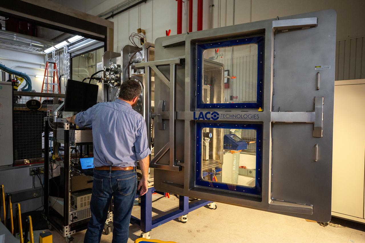
A team at NASA’s Kennedy Space Center in Florida tests a 3D printer on July 28, 2022, at the Florida spaceport’s Swamp Works, as part of the Relevant Environment Additive Construction Technology (REACT) project. Among the key objectives of the project is developing an architectural and structural design for a shelter that provides protection to habitable assets on the lunar surface. Testing REACT derives from NASA’s 2020 Announcement of Collaboration Opportunity with AI SpaceFactory – an architectural and construction technology company and winner of NASA’s 3D Printed Habitat Challenge.
A team at NASA’s Kennedy Space Center in Florida tests a 3D printer on July 28, 2022, at the Florida spaceport’s Swamp Works, as part of the Relevant Environment Additive Construction Technology (REACT) project. Among the key objectives of the project is developing an architectural and structural design for a shelter that provides protection to habitable assets on the lunar surface. Testing REACT derives from NASA’s 2020 Announcement of Collaboration Opportunity with AI SpaceFactory – an architectural and construction technology company and winner of NASA’s 3D Printed Habitat Challenge.

Chemist Tesia Irwin tests a 3D printer on July 28, 2022, at Swamp Works at NASA’s Kennedy Space Center in Florida, as part of the Relevant Environment Additive Construction Technology (REACT) project. Among the key objectives of the project is developing an architectural and structural design for a shelter that provides protection to habitable assets on the lunar surface. Testing REACT derives from NASA’s 2020 Announcement of Collaboration Opportunity with AI SpaceFactory – an architectural and construction technology company and winner of NASA’s 3D Printed Habitat Challenge.
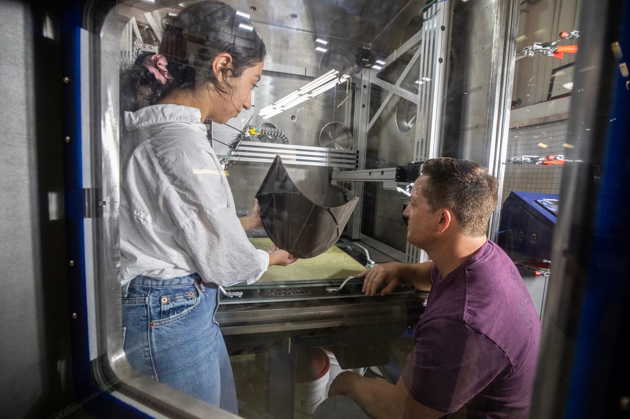
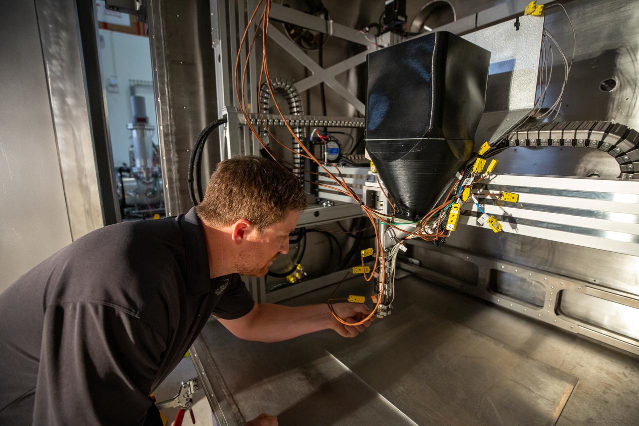
Chemist Nilab Azim, left, and Nathan Gelino, principal investigator with NASA’s Exploration Research and Technology programs, test a 3D printer on July 28, 2022, at Swamp Works at the agency’s Kennedy Space Center in Florida, as part of the Relevant Environment Additive Construction Technology (REACT) project. Among the key objectives of the project is developing an architectural and structural design for a shelter that provides protection to habitable assets on the lunar surface. Testing REACT derives from NASA’s 2020 Announcement of Collaboration Opportunity with AI SpaceFactory – an architectural and construction technology company and winner of NASA’s 3D Printed Habitat Challenge.
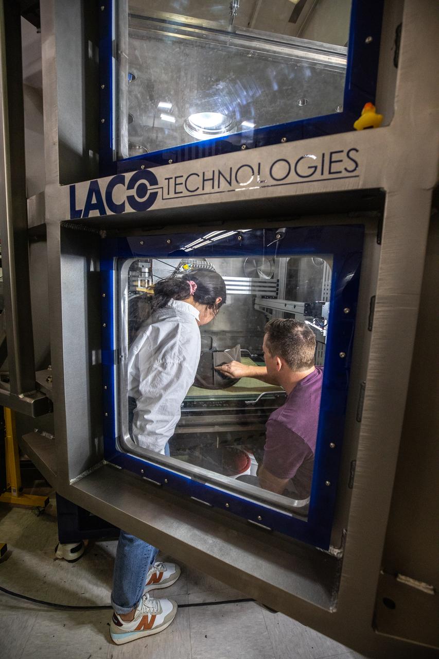
Chemist Nilab Azim, left, and Nathan Gelino, principal investigator with NASA’s Exploration Research and Technology programs, test a 3D printer on July 28, 2022, at Swamp Works at the agency’s Kennedy Space Center in Florida, as part of the Relevant Environment Additive Construction Technology (REACT) project. Among the key objectives of the project is developing an architectural and structural design for a shelter that provides protection to habitable assets on the lunar surface. Testing REACT derives from NASA’s 2020 Announcement of Collaboration Opportunity with AI SpaceFactory – an architectural and construction technology company and winner of NASA’s 3D Printed Habitat Challenge.
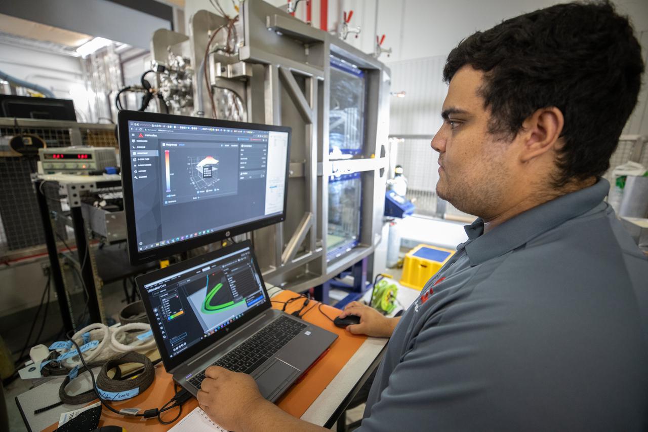
NASA Internships, Fellowships, and Scholarships (NIFS) intern Leonel Herrera tests a 3D printer on July 28, 2022, at Swamp Works at NASA’s Kennedy Space Center in Florida, as part of the Relevant Environment Additive Construction Technology (REACT) project. Among the key objectives of the project is developing an architectural and structural design for a shelter that provides protection to habitable assets on the lunar surface. Testing REACT derives from NASA’s 2020 Announcement of Collaboration Opportunity with AI SpaceFactory – an architectural and construction technology company and winner of NASA’s 3D Printed Habitat Challenge.
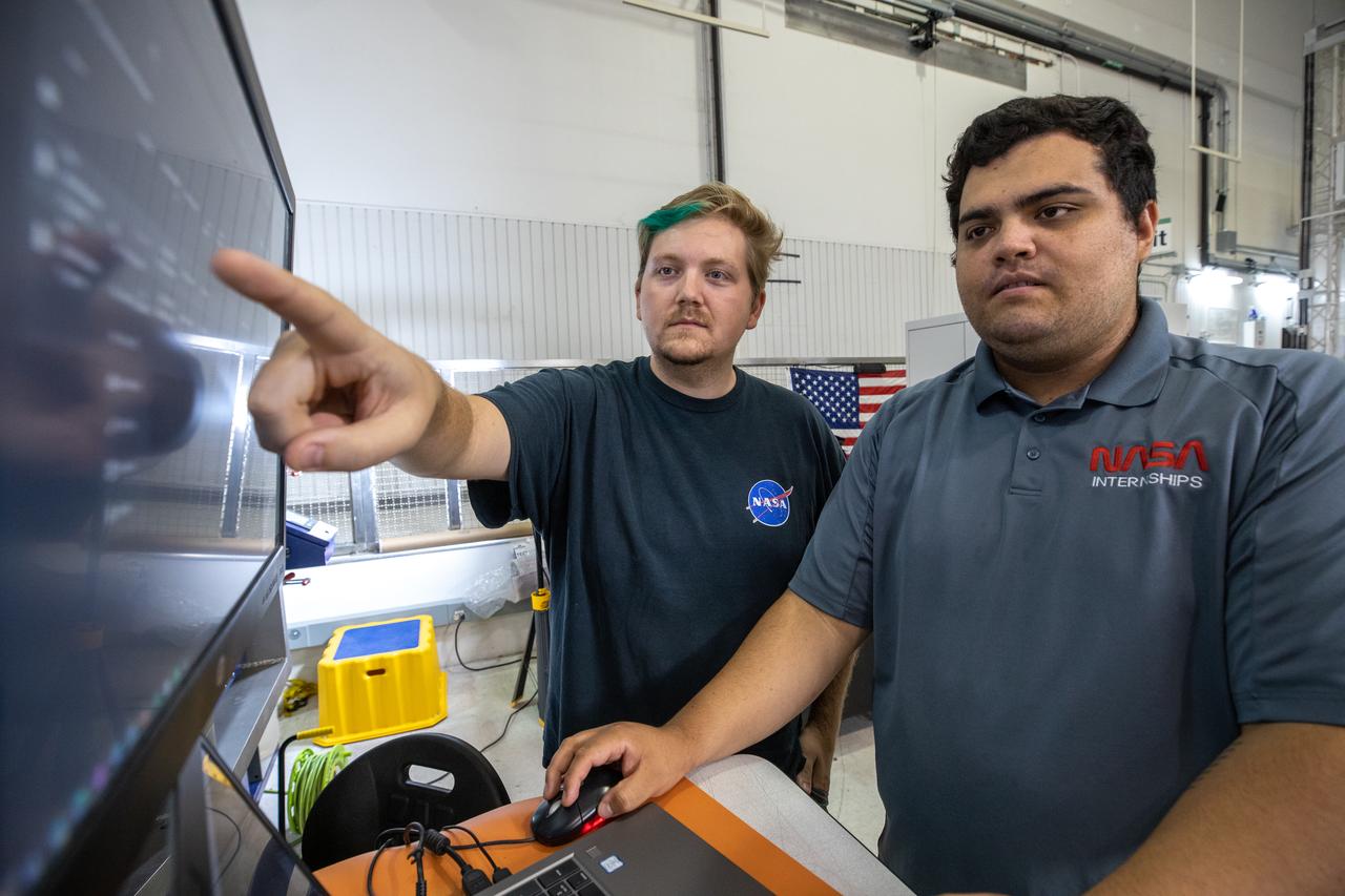
NASA engineer Evan Bell, left, and NASA Internships, Fellowships, and Scholarships (NIFS) intern Leonel Herrera test a 3D printer on July 28, 2022, at Swamp Works at NASA’s Kennedy Space Center in Florida, as part of the Relevant Environment Additive Construction Technology (REACT) project. Among the key objectives of the project is developing an architectural and structural design for a shelter that provides protection to habitable assets on the lunar surface. Testing REACT derives from NASA’s 2020 Announcement of Collaboration Opportunity with AI SpaceFactory – an architectural and construction technology company and winner of NASA’s 3D Printed Habitat Challenge.
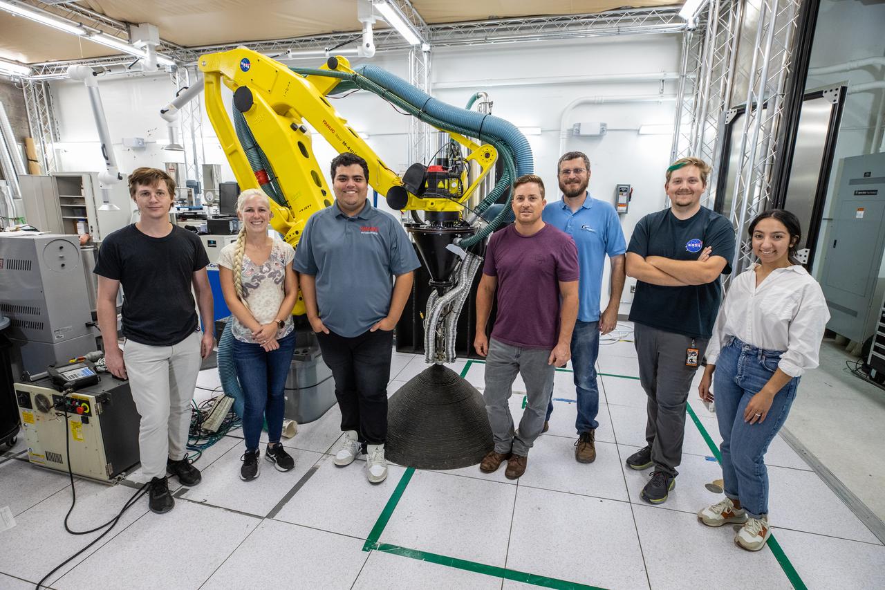
A team at NASA’s Kennedy Space Center in Florida poses with a Zero Launch Mass 3D printer on July 28, 2022, at the Florida spaceport’s Swamp Works, as part of the Relevant Environment Additive Construction Technology (REACT) project. Shown from left to right are: Tommy Lipscomb, materials engineer; Tesia Irwin, chemist; Leonel Herrera, NASA Internships, Fellowships, and Scholarships (NIFS) intern; Nathan Gelino, principal investigator; Matt Nugent, robotics engineer; Evan Bell, robotics engineer; and Nilab Azim, chemist. Among the key objectives of the project is developing an architectural and structural design for a shelter that provides protection to habitable assets on the lunar surface. Testing REACT derives from NASA’s 2020 Announcement of Collaboration Opportunity with AI SpaceFactory – an architectural and construction technology company and winner of NASA’s 3D Printed Habitat Challenge.

NASA Voyager 2 spacecraft flew by Triton, a moon of Neptune, in the summer of 1989. Dr. Paul Schenk, a scientist at the Lunar and Planetary Institute in Houston, used Voyager data to construct the best-ever global color map of Triton.
Josh Litofsky leads a Gateway lunar dust adhesion testing campaign at NASA’s Johnson Space Center in Houston. His team studies how lunar dust interacts with materials chosen for Gateway's construction. Here, Litofsky scoops lunar stimulant into a sample holder. Litofksy’s work seeks to validate the Gateway On-orbit Lunar Dust Modeling and Analysis Program (GOLDMAP), developed by Ronald Lee, also of Johnson Space Center. By considering factors such as the design and configuration of the space station, the materials used, and the unique conditions in lunar orbit, GOLDMAP helps predict how dust may move and settle on Gateway’s external surfaces.
/jsc2024e063104 (2)~medium.jpg)
Josh Litofsky leads a Gateway lunar dust adhesion testing campaign at NASA’s Johnson Space Center in Houston. His team studies how lunar dust interacts with materials chosen for Gateway's construction. Here, Litofsky carefully positions a sample holder inside a vacuum chamber. Litofksy’s work seeks to validate the Gateway On-orbit Lunar Dust Modeling and Analysis Program (GOLDMAP), developed by Ronald Lee, also of Johnson Space Center. By considering factors such as the design and configuration of the space station, the materials used, and the unique conditions in lunar orbit, GOLDMAP helps predict how dust may move and settle on Gateway’s external surfaces.
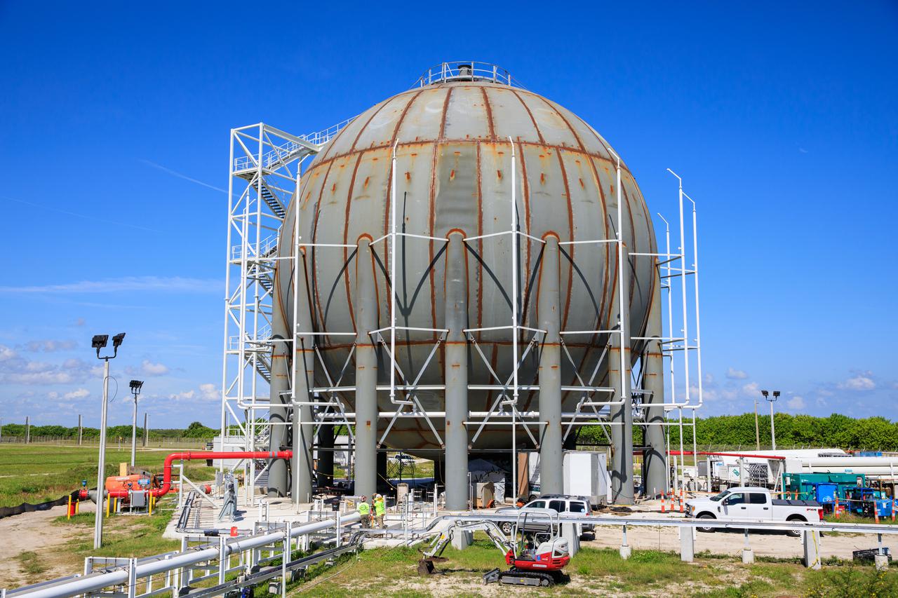
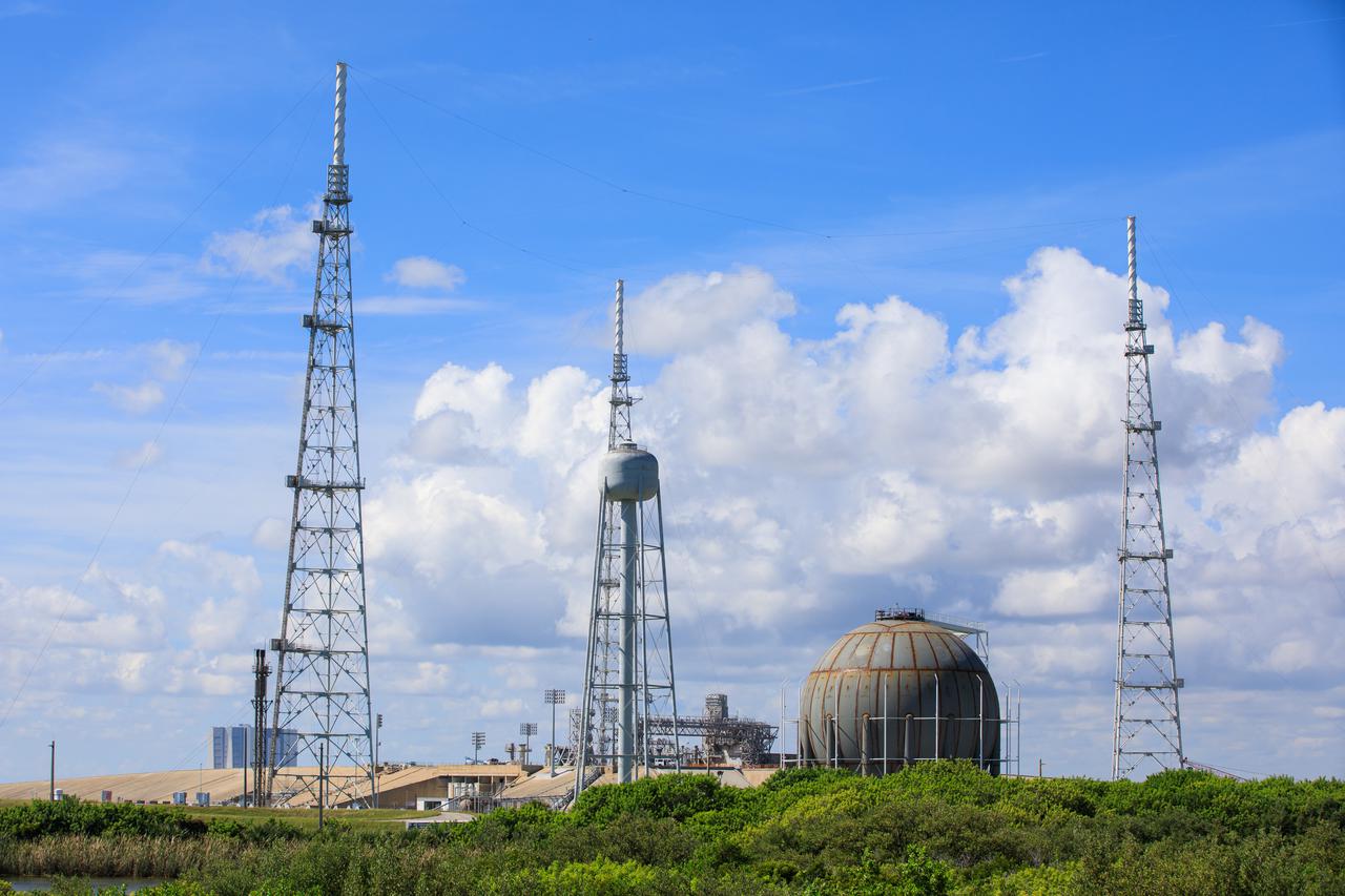
Seen here is a newly constructed liquid hydrogen (LH2) storage tank at Launch Pad 39B at NASA’s Kennedy Space Center in Florida on Oct. 1, 2021. With construction now complete, teams will focus on painting the tank next. The storage tank, capable of holding 1.25 million gallons of LH2, will be used to support future Artemis missions to the Moon and, eventually, Mars. Through Artemis, NASA will land the first woman and first person of color on the Moon, paving the way for a long-term presence in lunar orbit.
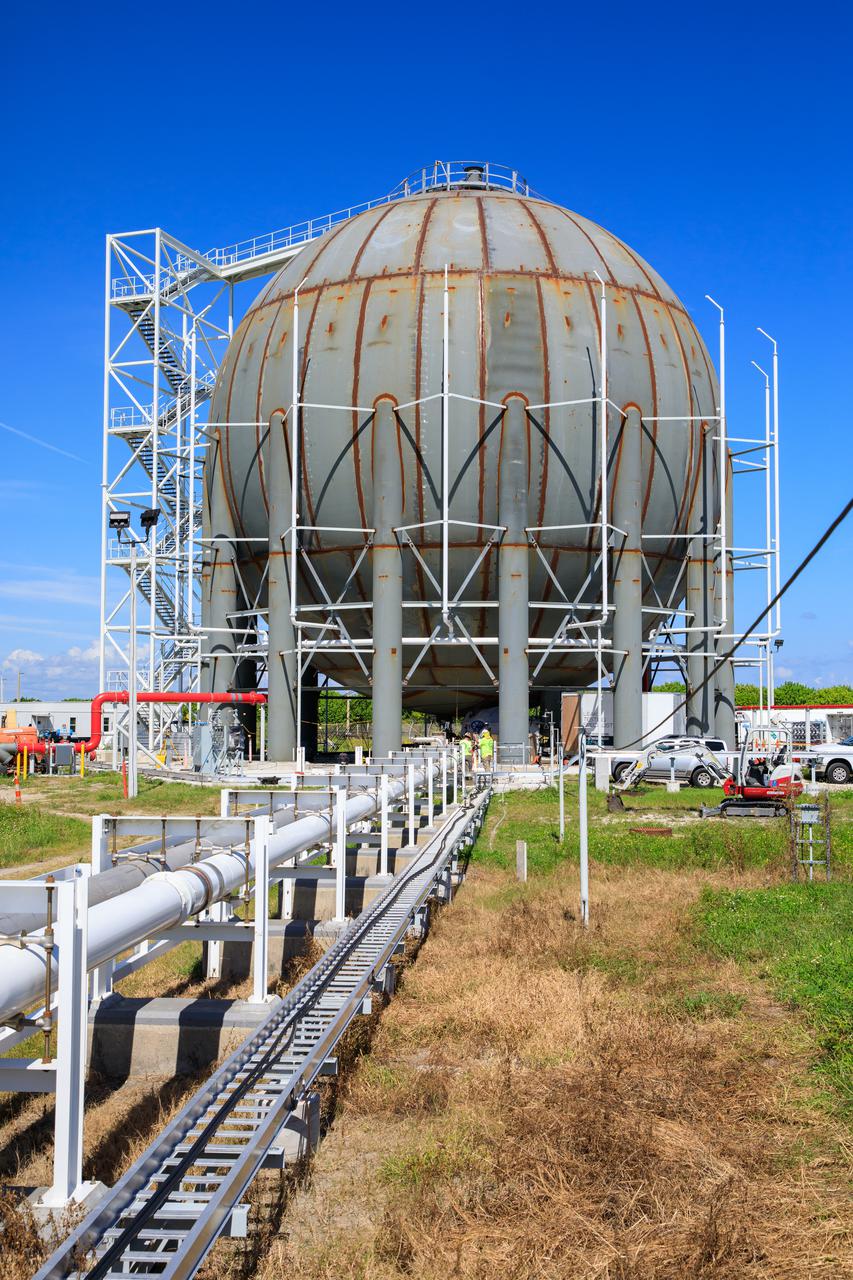
Seen here is a newly constructed liquid hydrogen (LH2) storage tank at Launch Pad 39B at NASA’s Kennedy Space Center in Florida on Oct. 1, 2021. With construction now complete, teams will focus on painting the tank next. The storage tank, capable of holding 1.25 million gallons of LH2, will be used to support future Artemis missions to the Moon and, eventually, Mars. Through Artemis, NASA will land the first woman and first person of color on the Moon, paving the way for a long-term presence in lunar orbit.
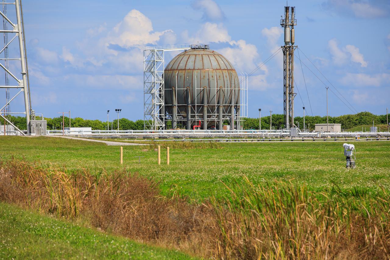
Seen here is a newly constructed liquid hydrogen (LH2) storage tank at Launch Pad 39B at NASA’s Kennedy Space Center in Florida on Oct. 1, 2021. With construction now complete, teams will focus on painting the tank next. The storage tank, capable of holding 1.25 million gallons of LH2, will be used to support future Artemis missions to the Moon and, eventually, Mars. Through Artemis, NASA will land the first woman and first person of color on the Moon, paving the way for a long-term presence in lunar orbit.
Seen here is a newly constructed liquid hydrogen (LH2) storage tank at Launch Pad 39B at NASA’s Kennedy Space Center in Florida on Oct. 1, 2021. With construction now complete, teams will focus on painting the tank next. The storage tank, capable of holding 1.25 million gallons of LH2, will be used to support future Artemis missions to the Moon and, eventually, Mars. Through Artemis, NASA will land the first woman and first person of color on the Moon, paving the way for a long-term presence in lunar orbit.
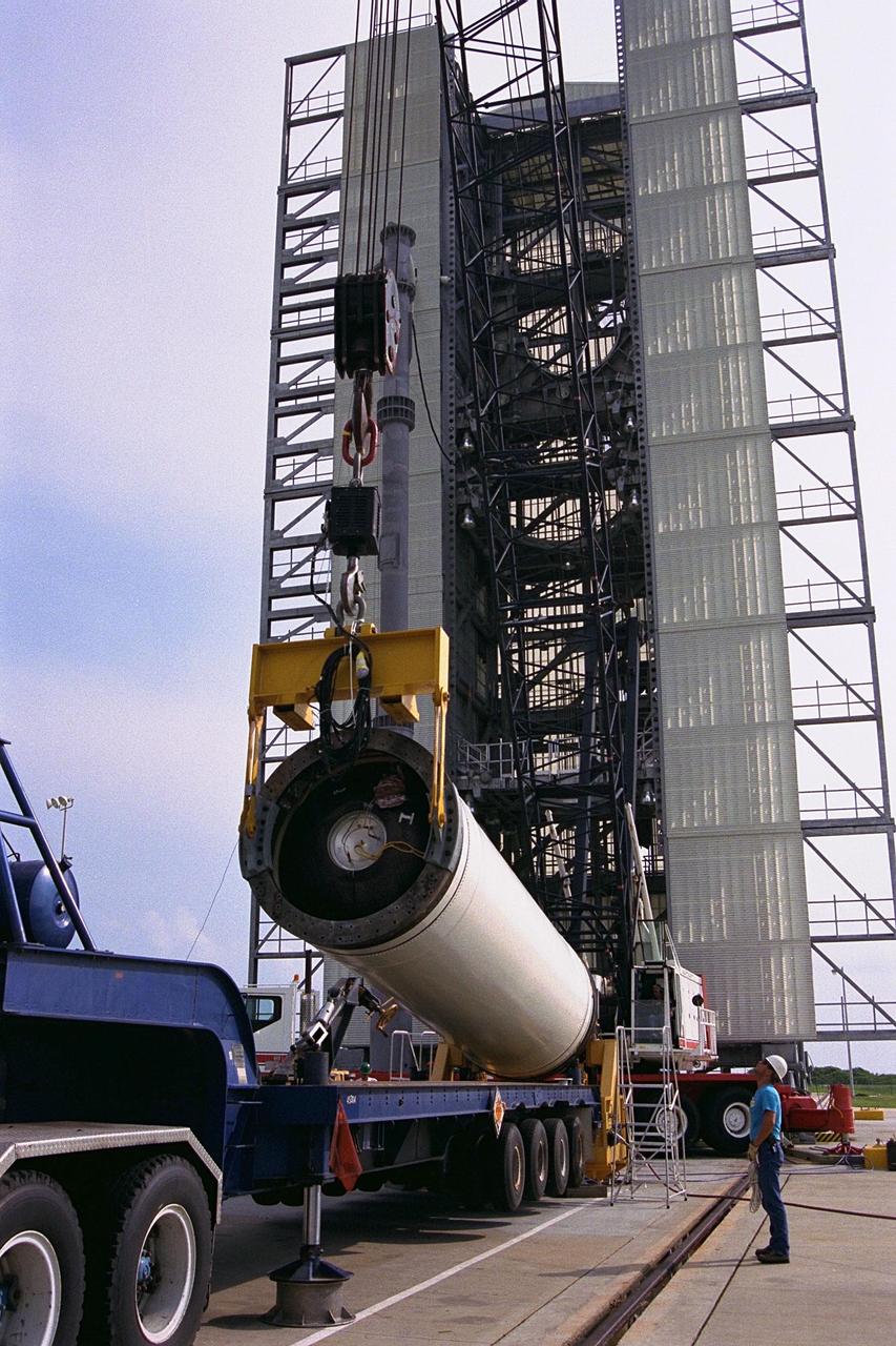
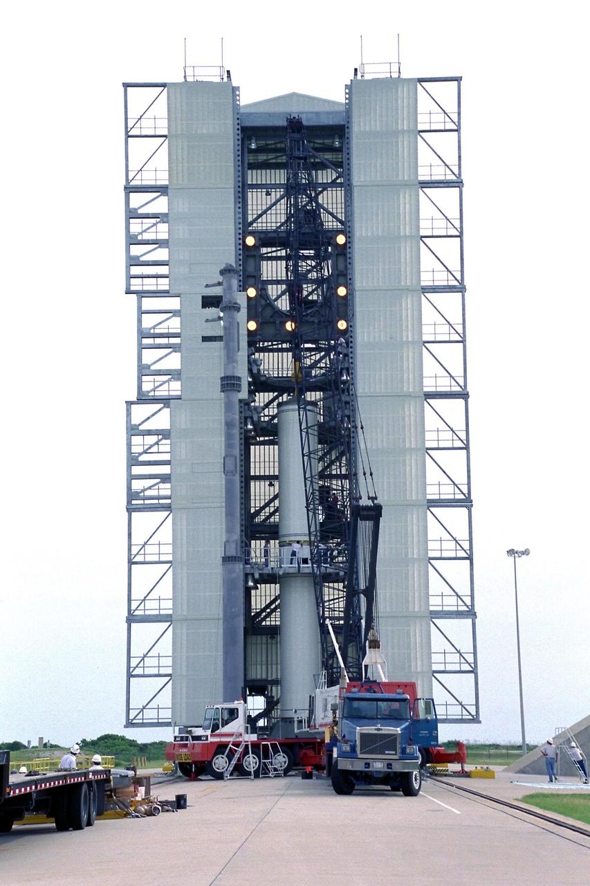
Workers hoist the first stage of a Lockheed Martin Launch Vehicle-2 (LMLV-2) for placement at Launch Complex 46 at Cape Canaveral Air Station (CCAS), Fla. The Lunar Prospector spacecraft is scheduled to launch aboard the LMLV-2 from CCAS in October for an 18-month mission that will orbit the Earth’s Moon to collect data from the lunar surface. Information gathered during the mission will allow construction of a detailed map of the surface composition of the Moon and will improve our understanding of its origin, evolution, current state, and resources
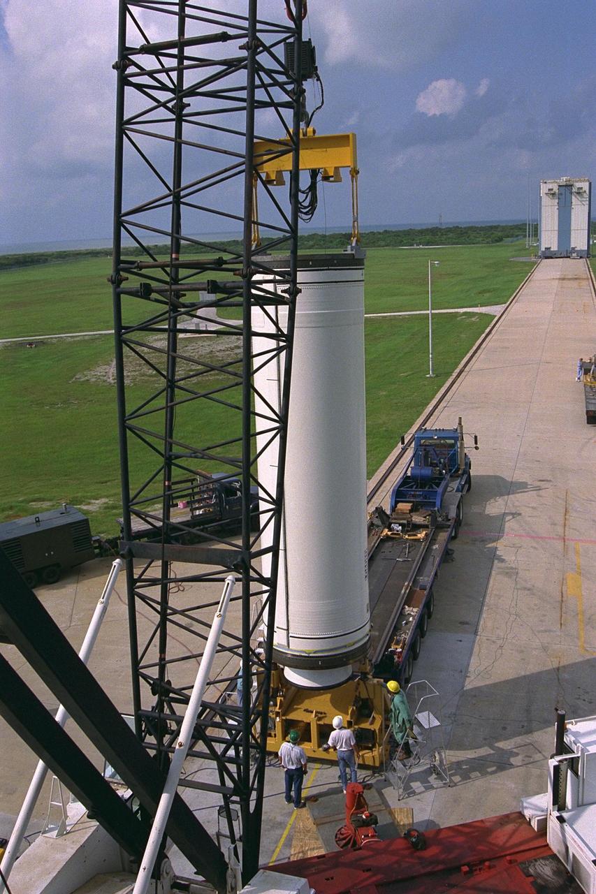
The second stage of the Lockheed Martin Launch Vehicle-2 (LMLV-2) is mated to its first stage at Launch Complex 46 at Cape Canaveral Air Station. The LMLV-2 will carry the Lunar Prospector spacecraft, scheduled to launch in October for an 18-month mission that will orbit the Earth’s moon to collect data from the lunar surface. Information gathered during the mission will allow construction of a detailed map of the surface composition of the moon and will improve our understanding of its origin, evolution, current state, and resources
Workers hoist the first stage of a Lockheed Martin Launch Vehicle-2 (LMLV-2) for placement at Launch Complex 46 at Cape Canaveral Air Station (CCAS), Fla. The Lunar Prospector spacecraft is scheduled to launch aboard the LMLV-2 from CCAS in October for an 18-month mission that will orbit the Earth’s Moon to collect data from the lunar surface. Information gathered during the mission will allow construction of a detailed map of the surface composition of the Moon and will improve our understanding of its origin, evolution, current state, and resources
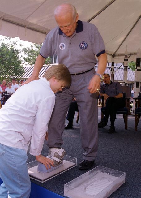
Apollo 11 Astronaut Buzz Aldrin has his footprints casted during the dedication ceremony of the rocket fountain at Building 4200 at Marshall Space Flight Center. The casts of Aldrin's footprints will be placed in the newly constructed Von Braun courtyard representing the accomplishments of the Apollo 11 lunar landing.

iss066e133942 (Feb. 2, 2022) --- ESA (European Space Agency) astronaut and Expedition 66 Flight Engineer Matthias Maurer works in the Harmony module using the portable glovebag for the Concrete Hardening experiment studying potential lunar and planetary construction techniques.

The M2-F1 was fitted with an ejection seat before the airtow flights began. The project selected the seat used in the T-37 as modified by the Weber Company to use a rocket rather than a ballistic charge for ejection. To test the ejection seat, the Flight Research Center's Dick Klein constructed a plywood mockup of the M2-F1's top deck and canopy. On the first firings, the test was unsuccessful, but on the final test the dummy in the seat landed safely. The M2-F1 ejection seat was later used in the two Lunar Landing Research Vehicles and the three Lunar Landing Training Vehicles. Three of them crashed, but in each case the pilot ejected from the vehicle successfully.
Thomas Lipscomb, a materials engineer at NASA’s Kennedy Space Center in Florida, prepares a vacuum chamber for testing 3D printing inside the Granular Mechanics and Regolith Operations (GMRO) lab at the spaceport’s Swamp Works on April 5, 2022. The testing is part of the Relevant Environment Additive Construction Technology (REACT) project, which derives from NASA’s 2020 Announcement of Collaboration Opportunity, with AI SpaceFactory – an architectural and construction technology company and winner of NASA’s 3D Printed Habitat Challenge – collaborating with Kennedy teams to build 3D-printed test structures using a composite made from polymers and a regolith simulant in a vacuum chamber that mimics environmental conditions on the Moon.
NASA engineer Evan Bell prepares a vacuum chamber for testing 3D printing inside the Granular Mechanics and Regolith Operations (GMRO) lab at Kennedy Space Center’s Swamp Works in Florida on April 5, 2022. The testing is part of the Relevant Environment Additive Construction Technology (REACT) project, which derives from NASA’s 2020 Announcement of Collaboration Opportunity, with AI SpaceFactory – an architectural and construction technology company and winner of NASA’s 3D Printed Habitat Challenge – collaborating with Kennedy teams to build 3D-printed test structures using a composite made from polymers and a regolith simulant in a vacuum chamber that mimics environmental conditions on the Moon.
Nathan Gelino, a principal investigator with the Exploration Research and Technology programs at Kennedy Space Center in Florida, prepares a vacuum chamber for testing 3D printing inside the Granular Mechanics and Regolith Operations (GMRO) lab at Kennedy’s Swamp Works on April 5, 2022. The testing is part of the Relevant Environment Additive Construction Technology (REACT) project, which derives from NASA’s 2020 Announcement of Collaboration Opportunity, with AI SpaceFactory – an architectural and construction technology company and winner of NASA’s 3D Printed Habitat Challenge – collaborating with Kennedy teams to build 3D-printed test structures using a composite made from polymers and a regolith simulant in a vacuum chamber that mimics environmental conditions on the Moon.
Engineer Matt Nugent prepares a vacuum chamber for testing 3D printing inside the Granular Mechanics and Regolith Operations (GMRO) lab at NASA Kennedy Space Center’s Swamp Works in Florida on April 5, 2022. The testing is part of the Relevant Environment Additive Construction Technology (REACT) project, which derives from NASA’s 2020 Announcement of Collaboration Opportunity, with AI SpaceFactory – an architectural and construction technology company and winner of NASA’s 3D Printed Habitat Challenge – collaborating with Kennedy teams to build 3D-printed test structures using a composite made from polymers and a regolith simulant in a vacuum chamber that mimics environmental conditions on the Moon.
A team at NASA’s Kennedy Space Center in Florida test a 3D printer inside a vacuum chamber at the Granular Mechanics and Regolith Operations (GMRO) lab inside the spaceport’s Swamp Works, as part of the Relevant Environment Additive Construction Technology (REACT) project on April 5, 2022. Testing REACT derives from NASA’s 2020 Announcement of Collaboration Opportunity, with AI SpaceFactory – an architectural and construction technology company and winner of NASA’s 3D Printed Habitat Challenge – collaborating with Kennedy teams to build 3D-printed test structures using a composite made from polymers and a regolith simulant in a vacuum chamber that mimics environmental conditions on the Moon.
A team of engineers and researchers prepares a vacuum chamber in the Granular Mechanics and Regolith Operations (GMRO) lab inside NASA Kennedy Space Center’s Swamp Works for testing 3D printing, as part of the Relevant Environment Additive Construction Technology (REACT) project at the Florida spaceport on April 5, 2022. The project derives from NASA’s 2020 Announcement of Collaboration Opportunity, with AI SpaceFactory – an architectural and construction technology company and winner of NASA’s 3D Printed Habitat Challenge – collaborating with Kennedy teams to build 3D-printed test structures using a composite made from polymers and a regolith simulant in a vacuum chamber that mimics environmental conditions on the Moon.
Joseliz Perez, a NASA intern at Kennedy Space Center in Florida, prepares a vacuum chamber for testing 3D printing inside the Granular Mechanics and Regolith Operations (GMRO) lab at the spaceport’s Swamp Works on April 5, 2022. The testing is part of the Relevant Environment Additive Construction Technology (REACT) project, which derives from NASA’s 2020 Announcement of Collaboration Opportunity, with AI SpaceFactory – an architectural and construction technology company and winner of NASA’s 3D Printed Habitat Challenge – collaborating with Kennedy teams to build 3D-printed test structures using a composite made from polymers and a regolith simulant in a vacuum chamber that mimics environmental conditions on the Moon.
Outside of Building 4200 at Marshall Space Flight Center, a courtyard was constructed in memory of Dr. Wernher von Braun and his contributions to the U. S. Space program. In the middle of the courtyard a fountain was built. The fountain was made operational prior to the 30th arniversary celebration of the Apollo 11 lunar landing. Attending the dedication ceremony were visiting Apollo astronauts and NASA's Safety and Assurance Director Rothenberg.
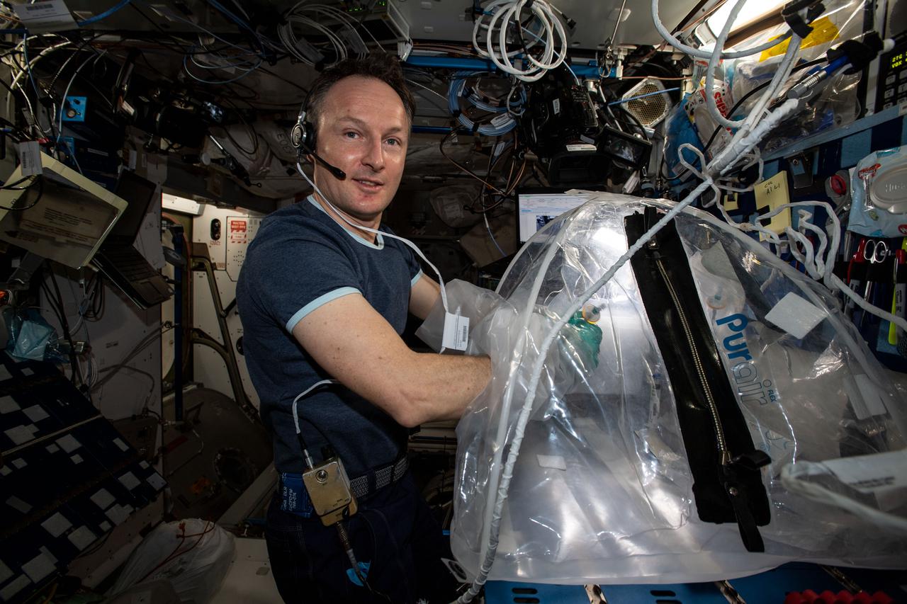
iss066e137033 (Feb. 1, 2022) --- ESA (European Space Agency) astronaut and Expedition 66 Flight Engineer Matthias Maurer explores how concrete hardens with the lack of gravity to inform future space construction techniques on lunar and planetary surfaces. Maurer conducts research operations in the portable glovebag with a variety of cement mixtures observing how pores, bubbles and crystals develop as the samples harden.
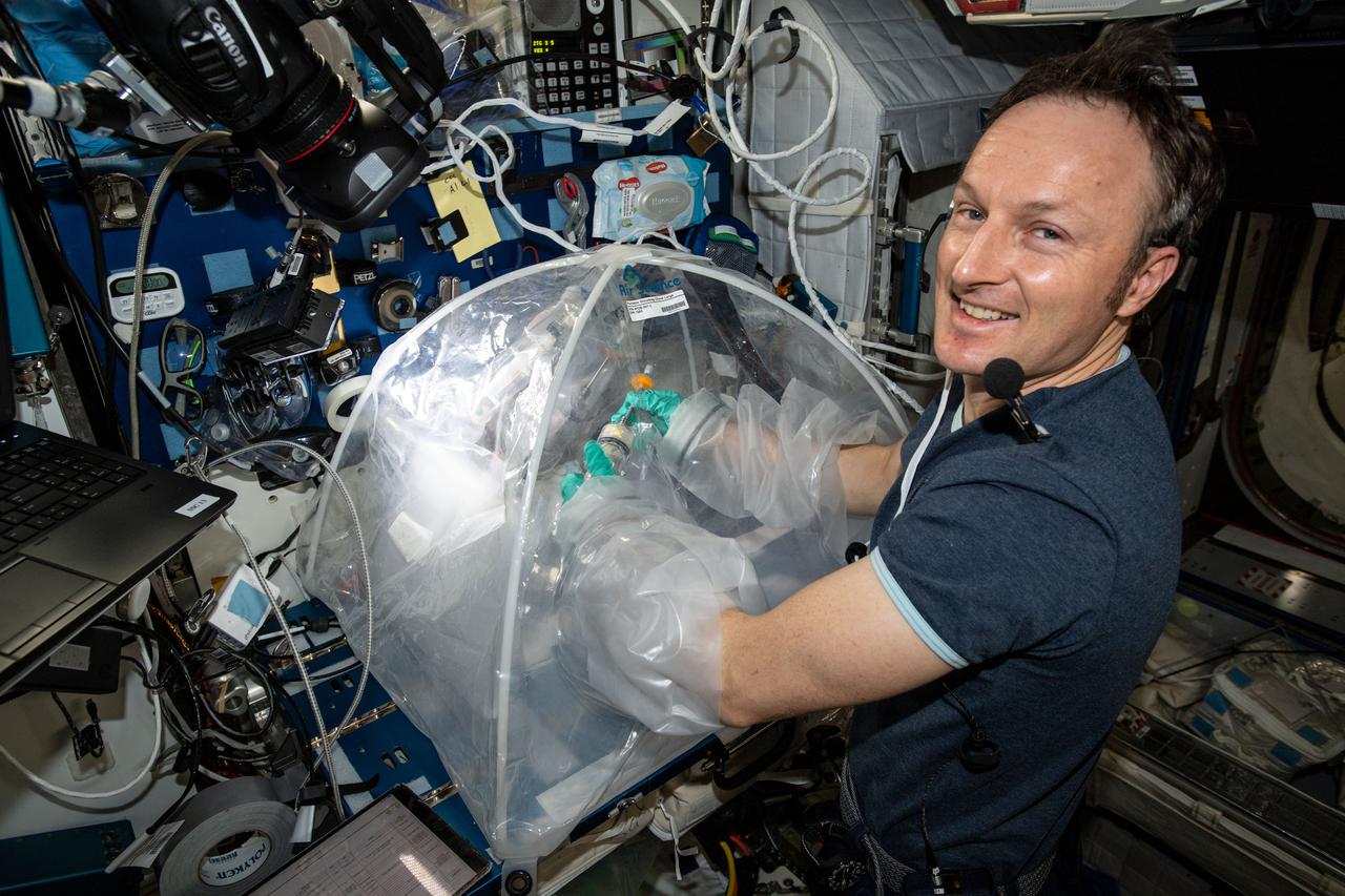
iss066e137028 (Feb. 1, 2022) --- ESA (European Space Agency) astronaut and Expedition 66 Flight Engineer Matthias Maurer explores how concrete hardens with the lack of gravity to inform future space construction techniques on lunar and planetary surfaces. Maurer conducts research operations in the portable glovebag with a variety of cement mixtures observing how pores, bubbles and crystals develop as the samples harden.
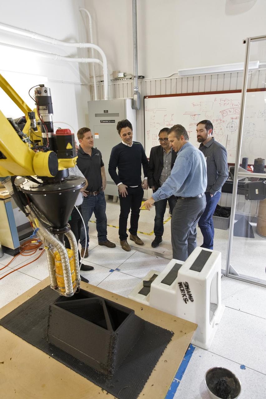
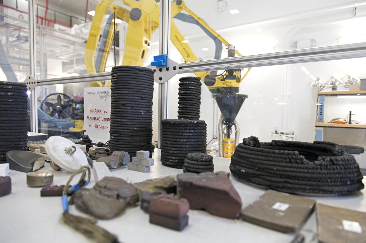
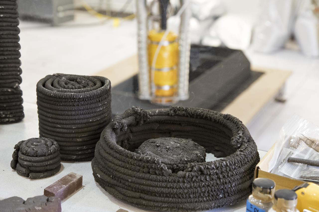
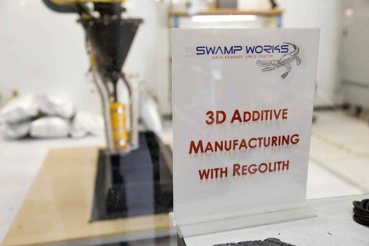
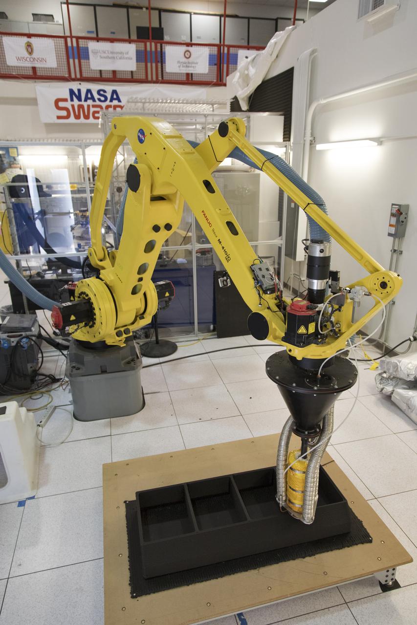
Researchers at NASA's Kennedy Space Center in Florida are developing a Zero Launch Mass 3-D printer at the center's Swamp Works. The printer can be used for construction projects on the Moon and Mars. Zero launch mass refers to the fact that the printer uses pellets made from simulated lunar regolith, or dirt, and polymers. This will prove that space explorers can use resources at their destination instead of taking everything with them, saving them launch mass and money. The Kennedy team is working with Marshall Space Flight Center in Huntsville, Alabama, and the U.S. Army Corps of Engineers to develop a system that can 3-D print barracks in remote locations on Earth, using the resources they have where they are.
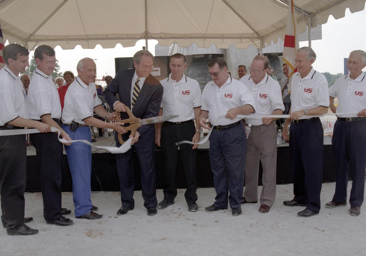
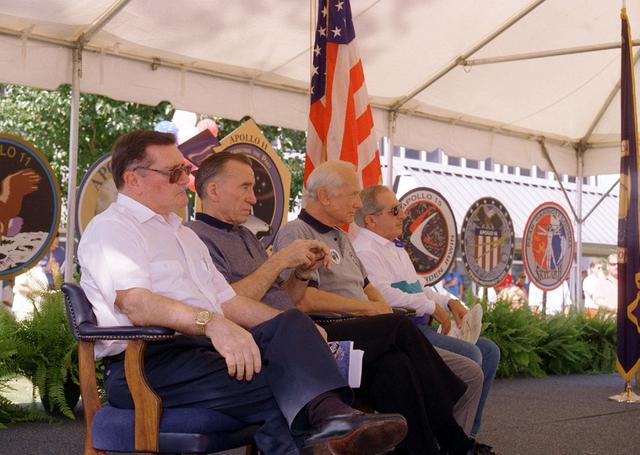
Alabama Governor Don Seigleman cuts the ribbon marking the dedication of the Saturn V rocket replica that was constructed at the U. S. Space and Rocket Center in honor of the 30th arniversary of the lunar landing. Accompanying the Governor are (L/R): Mike Wing, CEO US Space Rocket Center; Mike Gillespie, Madison County Commissioner, Dist. Seven; Buzz Aldrin, Apollo 11 Astronaut; Governor Seigleman; Walt Cunningham, Apollo 7 Astronaut; Dick Gordon, Apollo 12 Astronaut; Ed Mitchell, Apollo 14 Astronaut; Charlie Duke, Apollo 16 Astronaut; and Owen Garriott, Skylab 3 Astronaut.
A Zero Launch Mass 3-D printer is being developed by researchers in Swamp Works at NASA's Kennedy Space Center in Florida. The printer can be used for construction projects on the Moon and Mars. Zero launch mass refers to the fact that the printer uses pellets made from simulated lunar regolith, or dirt, and polymers. This will prove that space explorers can use resources at their destination instead of taking everything with them, saving them launch mass and money. The Kennedy team is working with Marshall Space Flight Center in Huntsville, Alabama, and the U.S. Army Corps of Engineers to develop a system that can 3-D print barracks in remote locations on Earth, using the resources they have where they are.
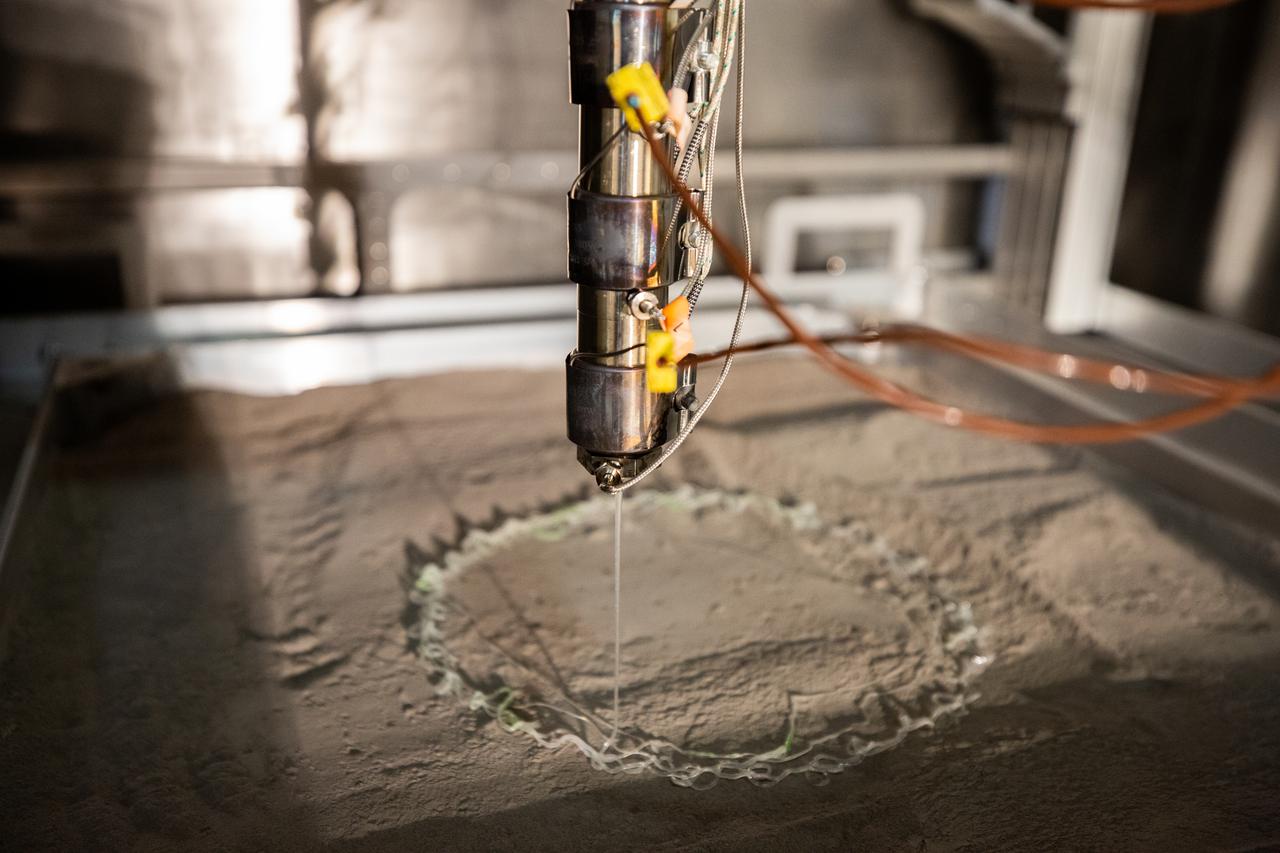
A Zero Launch Mass 3-D printer is being tested at the Swamp Works at NASA's Kennedy Space Center in Florida. The printer can be used for construction projects on the Moon and Mars. Zero launch mass refers to the fact that the printer uses pellets made from simulated lunar regolith, or dirt, and polymers. This will prove that space explorers can use resources at their destination instead of taking everything with them, saving them launch mass and money. The Kennedy team is working with Marshall Space Flight Center in Huntsville, Alabama, and the U.S. Army Corps of Engineers to develop a system that can 3-D print barracks in remote locations on Earth, using the resources they have where they are.
Researchers demonstrate a Zero Launch Mass 3-D printer in Swamp Works at NASA's Kennedy Space Center in Florida. The printer can be used for construction projects on the Moon and Mars. Zero launch mass refers to the fact that the printer uses pellets made from simulated lunar regolith, or dirt, and polymers. This will prove that space explorers can use resources at their destination instead of taking everything with them, saving them launch mass and money. The Kennedy team is working with Marshall Space Flight Center in Huntsville, Alabama, and the U.S. Army Corps of Engineers to develop a system that can 3-D print barracks in remote locations on Earth, using the resources they have where they are.
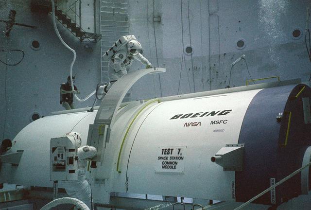
Skylab's success proved that scientific experimentation in a low gravity environment was essential to scientific progress. A more permanent structure was needed to provide this space laboratory. President Ronald Reagan, on January 25, 1984, during his State of the Union address, claimed that the United States should exploit the new frontier of space, and directed NASA to build a permanent marned space station within a decade. The idea was that the space station would not only be used as a laboratory for the advancement of science and medicine, but would also provide a staging area for building a lunar base and manned expeditions to Mars and elsewhere in the solar system. President Reagan invited the international community to join with the United States in this endeavour. NASA and several countries moved forward with this concept. By December 1985, the first phase of the space station was well underway with the design concept for the crew compartments and laboratories. Pictured are two NASA astronauts, at Marshall Space Flight Center's (MSFC) Neutral Buoyancy Simulator (NBS), practicing construction techniques they later used to construct the space station after it was deployed.
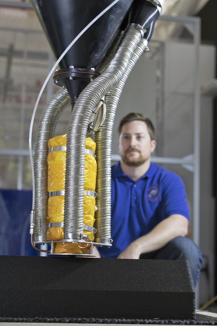
Nathan Gelino, a NASA research engineer at Kennedy Space Center in Florida, is working on a Zero Launch Mass 3-D printer in the center's Swamp Works that can be used for construction projects on the Moon and Mars, and even for troops in remote locations here on Earth. Zero launch mass refers to the fact that the printer uses pellets made from simulated lunar regolith, or dirt, and polymers to prove that space explorers can use resources at their destination instead of taking everything with them, saving them launch mass and money. Gelino and his team are working with Marshall Space Flight Center in Huntsville, Alabama, and the U.S. Army Corps of Engineers to develop a system that can 3-D print barracks in remote locations on Earth, using the resources they have where they are.
Research engineers at NASA's Kennedy Space Center in Florida are working on a Zero Launch Mass 3-D printer at the center's Swamp Works. The printer can be used for construction projects on the Moon and Mars, and even for troops in remote locations on Earth. Zero launch mass refers to the fact that the printer uses pellets made from simulated lunar regolith, or dirt, and polymers to prove that space explorers can use resources at their destination instead of taking everything with them, saving them launch mass and money. The group is working with Marshall Space Flight Center in Huntsville, Alabama, and the U.S. Army Corps of Engineers to develop a system that can 3-D print barracks in remote locations on Earth, using the resources they have where they are.
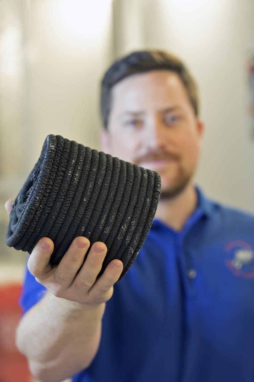
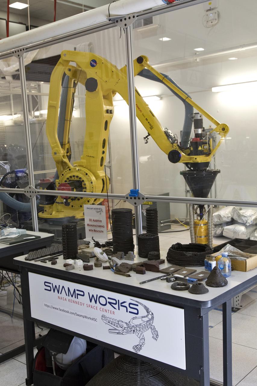
Nathan Gelino, a NASA research engineer at Kennedy Space Center in Florida displays a 3-D printed cylinder used for compression testing. Engineers at the center’s Swamp Works measured how much force it takes to break the structure before moving on to 3-D printing with a simulated lunar regolith, or dirt, and polymers. Next, Gelino and his group are working on a Zero Launch Mass 3-D printer that can be used for construction projects on the Moon and Mars, even for troops in remote locations here on Earth. Zero launch mass refers to the fact that the printer uses these pellets to prove that space explorers can use resources at their destination instead of taking everything with them, saving them launch mass and money. Gelino and his team are working with Marshall Space Flight Center in Huntsville, Alabama, and the U.S. Army Corps of Engineers to develop a system that can 3-D print barracks in remote locations on Earth, using the resources they have where they are.
Pellets made from simulated lunar regolith, or dirt, and polymers are being used to test a Zero Launch Mass 3-D printer in the Swamp Works at NASA's Kennedy Space Center in Florida. The printer can be used for construction projects on the Moon and Mars, and even for troops in remote locations on Earth. Zero launch mass refers to the fact that the printer uses these pellets to prove that space explorers can use resources at their destination instead of taking everything with them, saving them launch mass and money. The group is working with Marshall Space Flight Center in Huntsville, Alabama, and the U.S. Army Corps of Engineers to develop a system that can 3-D print barracks in remote locations on Earth, using the resources they have where they are.
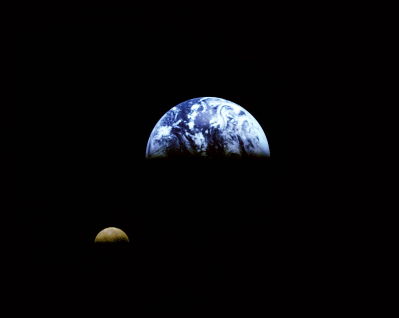
Eight days after its encounter with the Earth, the Galileo spacecraft was able to look back and capture this remarkable view of the Moon in orbit about the Earth, taken from a distance of about 6.2 million kilometers (3.9 million miles). The picture was constructed from images taken through the violet, red, and 1.0-micron infrared filters. The Moon is in the foreground, moving from left to right. The brightly-colored Earth contrasts strongly with the Moon, which reflects only about one-third as much sunlight as the Earth. Contrast and color have been computer-enhanced for both objects to improve visibility. Antarctica is visible through clouds (bottom). The Moon's far side is seen; the shadowy indentation in the dawn terminator is the south-Pole/Aitken Basin, one of the largest and oldest lunar impact features. Alternate Jet Propulsion Laboratory (JPL) number is P-41508. View appears in the Space News Roundup v32 n1 p1, 01-11-93.
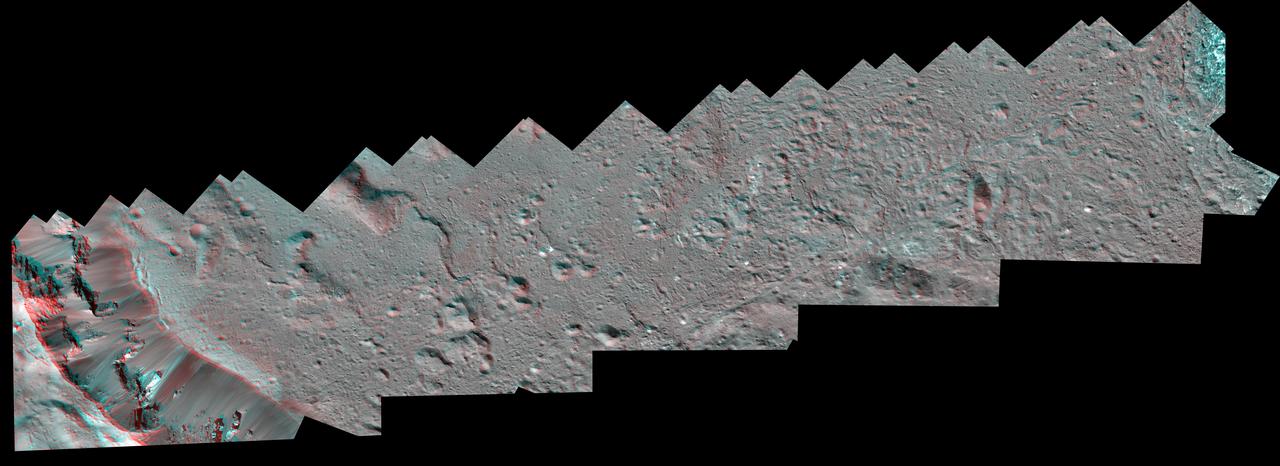
The Dawn spacecraft captured these stereo views of Occator Crater on the dwarf planet Ceres in 2018. More than 70 framing camera images were used to construct this anaglyph view (which requires red-blue stereo glasses for viewing) of the southeastern floor of the crater, including the rim at far left in this view. This area is largely covered with impact melt and features a variety of pits and low mounds, some of which are related to impact debris but others to subsurface brine seepage and deposition. The spatial resolution of the stereo images is about 11 feet (3.5 meters) per pixel. Occator Crater, named after the Roman god of the agricultural practice of harrowing, is about 57 miles (92 kilometers) in diameter. The conclusion of Dawn's mission operations was Oct. 31, 2018, when the spacecraft depleted its hydrazine used for attitude control. This image was produced by Dr. Paul Schenk at the Lunar and Planetary Institute in Houston. https://photojournal.jpl.nasa.gov/catalog/PIA24061
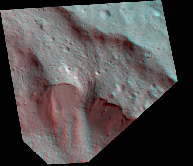
The Dawn spacecraft captured these stereo images of Occator crater on the dwarf planet Ceres in 2018. Framing camera images were used to construct this anaglyph view (which requires red-blue stereo glasses for viewing) of part of the northeastern rim of the crater. This area is approximately 4 miles (7 kilometers) wide and features a thin mantling layer of impact melt draped over faulted terrace blocks. Impact melt flowed through a gap in the blocks in the center of the frame. The spatial resolution of the stereo images is about 11 feet (3.5 meters) per pixel. Occator Crater, named after the Roman god of the agricultural practice of harrowing, is about 57 miles (92 kilometers) in diameter. The conclusion of Dawn's mission operations was Oct. 31, 2018, when the spacecraft depleted its hydrazine used for attitude control. This image was produced by Dr. Paul Schenk at the Lunar and Planetary Institute in Houston. https://photojournal.jpl.nasa.gov/catalog/PIA24064
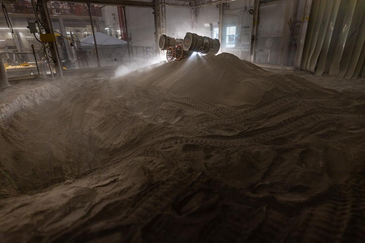
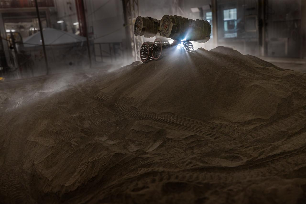
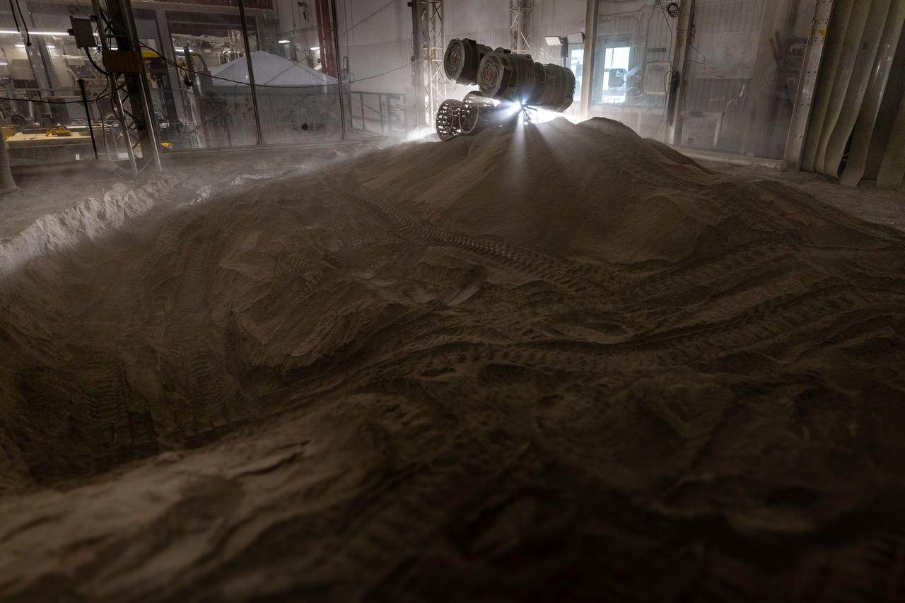
NASA’s RASSOR (Regolith Advanced Surface Systems Operations Robot) manipulates simulated regolith, or lunar dust found on the Moon’s surface, to create a three-foot berm during a site preparation test inside of the Granular Mechanics and Regolith Operations Lab at the agency’s Kennedy Space Center in Florida on Tuesday, June 3, 2025. The opposing motion of the bucket drums helps RASSOR grip the surface in low-gravity environments like the Moon or Mars. With this unique capability, RASSOR can traverse the rough surface to dig, load, haul, and dump regolith that could be used in construction or broken down into hydrogen, oxygen, or water, resources critical for sustaining human presence. RASSOR represents an earlier generation technology that informed the development of NASA’s IPEx (In-Situ Resource Utilization Pilot Excavator), serving as a precursor and foundational platform for the advanced excavation systems and autonomous capabilities now being demonstrated by this Moon-mining robot.
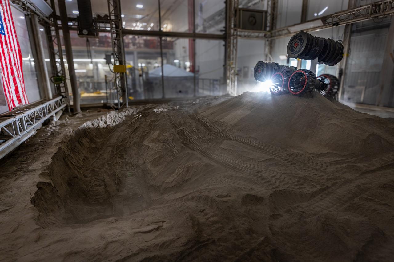
NASA’s RASSOR (Regolith Advanced Surface Systems Operations Robot) manipulates simulated regolith, or lunar dust found on the Moon’s surface, to create a three-foot berm during a site preparation test inside of the Granular Mechanics and Regolith Operations Lab at the agency’s Kennedy Space Center in Florida on Tuesday, June 3, 2025. The opposing motion of the bucket drums helps RASSOR grip the surface in low-gravity environments like the Moon or Mars. With this unique capability, RASSOR can traverse the rough surface to dig, load, haul, and dump regolith that could be used in construction or broken down into hydrogen, oxygen, or water, resources critical for sustaining human presence. RASSOR represents an earlier generation technology that informed the development of NASA’s IPEx (In-Situ Resource Utilization Pilot Excavator), serving as a precursor and foundational platform for the advanced excavation systems and autonomous capabilities now being demonstrated by this Moon-mining robot.
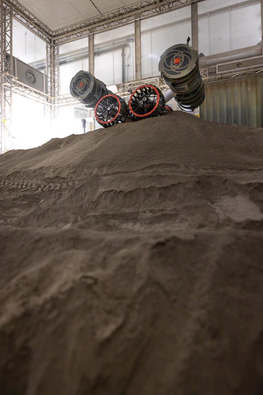
NASA’s RASSOR (Regolith Advanced Surface Systems Operations Robot) manipulates simulated regolith, or lunar dust found on the Moon’s surface, to create a three-foot berm during a site preparation test inside of the Granular Mechanics and Regolith Operations Lab at the agency’s Kennedy Space Center in Florida on Tuesday, June 3, 2025. The opposing motion of the bucket drums helps RASSOR grip the surface in low-gravity environments like the Moon or Mars. With this unique capability, RASSOR can traverse the rough surface to dig, load, haul, and dump regolith that could be used in construction or broken down into hydrogen, oxygen, or water, resources critical for sustaining human presence. RASSOR represents an earlier generation technology that informed the development of NASA’s IPEx (In-Situ Resource Utilization Pilot Excavator), serving as a precursor and foundational platform for the advanced excavation systems and autonomous capabilities now being demonstrated by this Moon-mining robot.
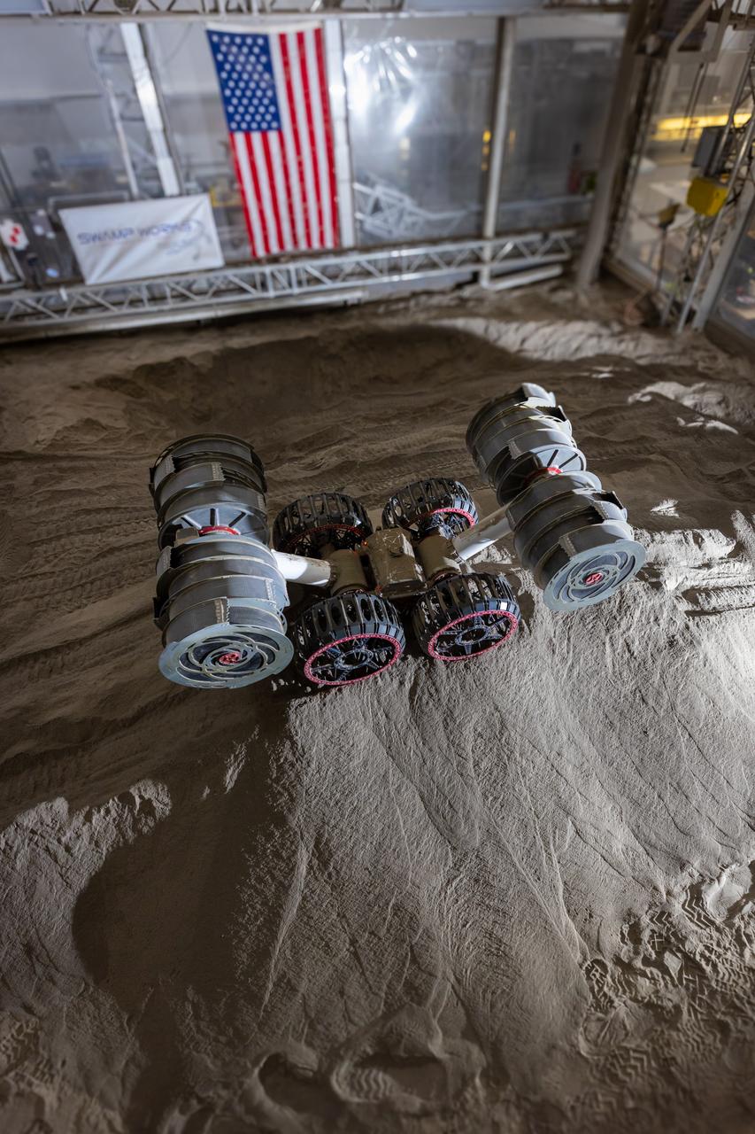
NASA’s RASSOR (Regolith Advanced Surface Systems Operations Robot) manipulates simulated regolith, or lunar dust found on the Moon’s surface, to create a three-foot berm during a site preparation test inside of the Granular Mechanics and Regolith Operations Lab at the agency’s Kennedy Space Center in Florida on Tuesday, June 3, 2025. The opposing motion of the bucket drums helps RASSOR grip the surface in low-gravity environments like the Moon or Mars. With this unique capability, RASSOR can traverse the rough surface to dig, load, haul, and dump regolith that could be used in construction or broken down into hydrogen, oxygen, or water, resources critical for sustaining human presence. RASSOR represents an earlier generation technology that informed the development of NASA’s IPEx (In-Situ Resource Utilization Pilot Excavator), serving as a precursor and foundational platform for the advanced excavation systems and autonomous capabilities now being demonstrated by this Moon-mining robot.
NASA’s RASSOR (Regolith Advanced Surface Systems Operations Robot) manipulates simulated regolith, or lunar dust found on the Moon’s surface, to create a three-foot berm during a site preparation test inside of the Granular Mechanics and Regolith Operations Lab at the agency’s Kennedy Space Center in Florida on Tuesday, June 3, 2025. The opposing motion of the bucket drums helps RASSOR grip the surface in low-gravity environments like the Moon or Mars. With this unique capability, RASSOR can traverse the rough surface to dig, load, haul, and dump regolith that could be used in construction or broken down into hydrogen, oxygen, or water, resources critical for sustaining human presence. RASSOR represents an earlier generation technology that informed the development of NASA’s IPEx (In-Situ Resource Utilization Pilot Excavator), serving as a precursor and foundational platform for the advanced excavation systems and autonomous capabilities now being demonstrated by this Moon-mining robot.
NASA’s RASSOR (Regolith Advanced Surface Systems Operations Robot) manipulates simulated regolith, or lunar dust found on the Moon’s surface, to create a three-foot berm during a site preparation test inside of the Granular Mechanics and Regolith Operations Lab at the agency’s Kennedy Space Center in Florida on Tuesday, June 3, 2025. The opposing motion of the bucket drums helps RASSOR grip the surface in low-gravity environments like the Moon or Mars. With this unique capability, RASSOR can traverse the rough surface to dig, load, haul, and dump regolith that could be used in construction or broken down into hydrogen, oxygen, or water, resources critical for sustaining human presence. RASSOR represents an earlier generation technology that informed the development of NASA’s IPEx (In-Situ Resource Utilization Pilot Excavator), serving as a precursor and foundational platform for the advanced excavation systems and autonomous capabilities now being demonstrated by this Moon-mining robot.
Research engineers at NASA's Kennedy Space Center in Florida are working on a Zero Launch Mass 3-D printer at the center's Swamp Works. The printer can be used for construction projects on the Moon and Mars, and even for troops in remote locations on Earth. Zero launch mass refers to the fact that the printer uses pellets made from simulated lunar regolith, or dirt, and polymers to prove that space explorers can use resources at their destination instead of taking everything with them, saving them launch mass and money. The group is working with Marshall Space Flight Center in Huntsville, Alabama, and the U.S. Army Corps of Engineers to develop a system that can 3-D print barracks in remote locations on Earth, using the resources they have where they are.
A Zero Launch Mass 3-D printer is being tested at the Swamp Works at NASA's Kennedy Space Center in Florida. The printer can be used for construction projects on the Moon and Mars, and even for troops in remote locations on Earth. Zero launch mass refers to the fact that the printer uses pellets made from simulated lunar regolith, or dirt, and polymers to prove that space explorers can use resources at their destination instead of taking everything with them, saving them launch mass and money. The group is working with Marshall Space Flight Center in Huntsville, Alabama, and the U.S. Army Corps of Engineers to develop a system that can 3-D print barracks in remote locations on Earth, using the resources they have where they are.
A Zero Launch Mass 3-D printer is being tested at the Swamp Works at NASA's Kennedy Space Center in Florida. The printer can be used for construction projects on the Moon and Mars, and even for troops in remote locations on Earth. Zero launch mass refers to the fact that the printer uses pellets made from simulated lunar regolith, or dirt, and polymers to prove that space explorers can use resources at their destination instead of taking everything with them, saving them launch mass and money. The group is working with Marshall Space Flight Center in Huntsville, Alabama, and the U.S. Army Corps of Engineers to develop a system that can 3-D print barracks in remote locations on Earth, using the resources they have where they are.
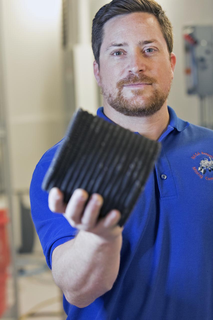
Nathan Gelino, a NASA research engineer at Kennedy Space Center in Florida displays a 3-D printed cylinder used for compression testing. Engineers at the center’s Swamp Works measured how much force it takes to break the structure before moving on to 3-D printing with a simulated lunar regolith, or dirt, and polymers. Next, Gelino and his group are working on a Zero Launch Mass 3-D printer that can be used for construction projects on the Moon and Mars, even for troops in remote locations here on Earth. Zero launch mass refers to the fact that the printer uses these pellets to prove that space explorers can use resources at their destination instead of taking everything with them, saving them launch mass and money. Gelino and his team are working with Marshall Space Flight Center in Huntsville, Alabama, and the U.S. Army Corps of Engineers to develop a system that can 3-D print barracks in remote locations on Earth, using the resources they have where they are.
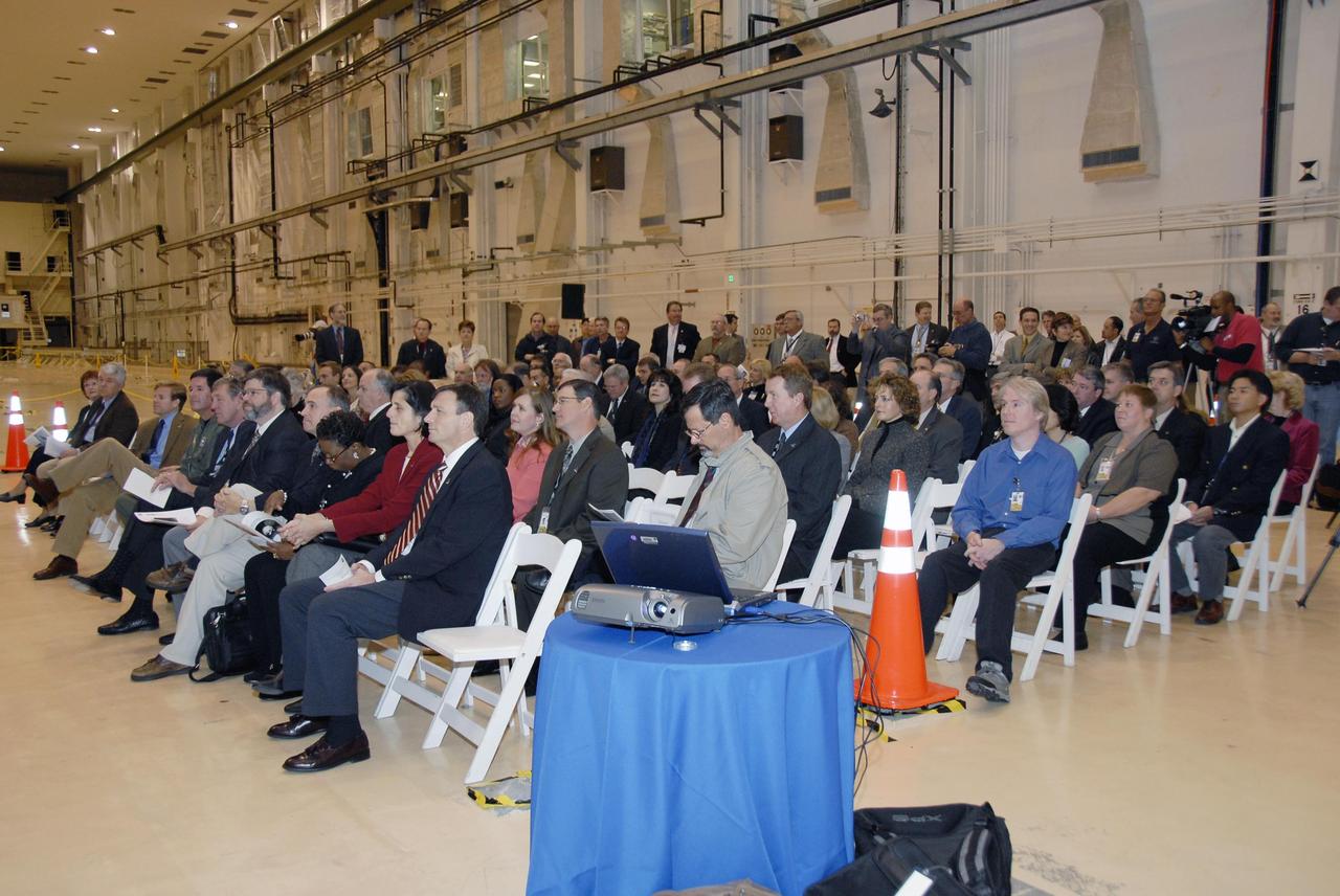
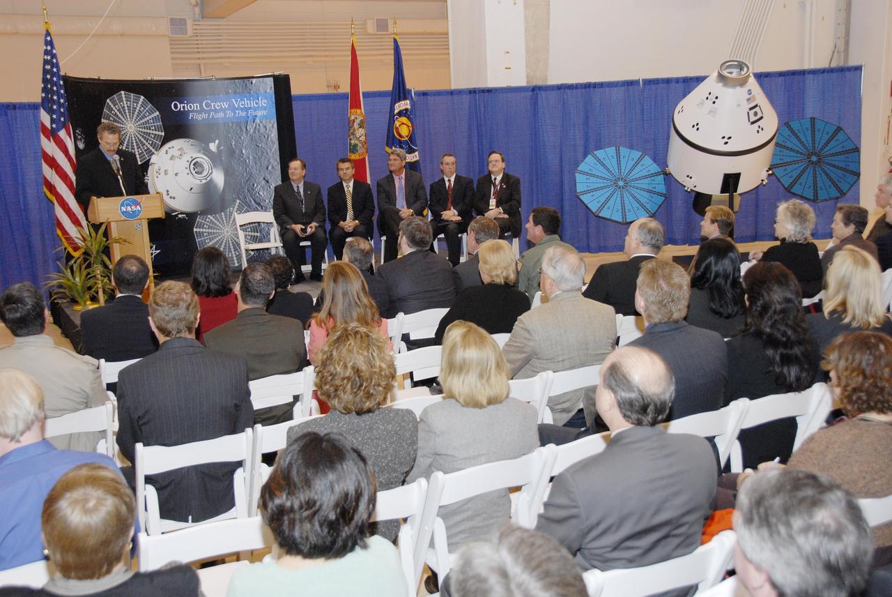
KENNEDY SPACE CENTER, FLA. -- Employees and guests are seated in the Operations and Checkout (O&C) Building high bay for the ceremony commemorating the bay's transition for use by the Constellation Program. Originally built to process space vehicles in the Apollo era, the O&C Building will serve as the final assembly facility for the Orion crew exploration vehicle. Orion, America's human spaceflight vehicle of the future, will be capable of transporting four crewmembers for lunar missions and later will support crew transfers for Mars missions. Each Orion spacecraft also may be used to support up to six crewmembers to the International Space Station after the space shuttle is retired in 2010. Design, development and construction of Orion's components will be performed by Lockheed Martin for NASA at facilities throughout the country. Photo credit: NASA/Kim Shiflett
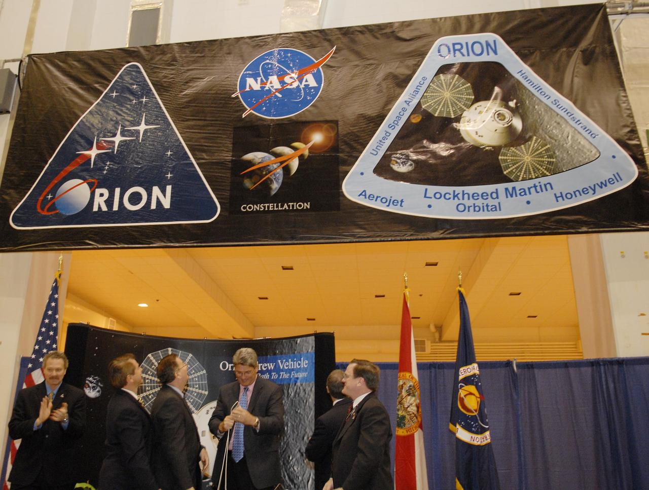
KENNEDY SPACE CENTER, FLA. -- After a ceremony to commemorate the transition of the historic Operations and Checkout (O&C) Building high bay for use by the Constellation Program, representatives from NASA, Lockheed Martin, Space Florida and the state of Florida look at the banner, unfurled by Kennedy Space Center Director Bill Parsons (center), spotlighting the Orion crew exploration vehicle that will be assembled in the O&C. From left are Russell Romanella, director of the International Space Station/Payload Processing Directorate at Kennedy Space Center; Thad Altman, representative of the State of Florida; Cleon Lacefield, Lockheed Martin program manager; Parsons; Steve Koller, executive director of Space Florida (turned away); and Skip Hatfield, Orion Project manager. Originally built to process space vehicles in the Apollo era, the O&C Building will serve as the final assembly facility for the Orion crew exploration vehicle. Orion, America's human spaceflight vehicle of the future, will be capable of transporting four crewmembers for lunar missions and later will support crew transfers for Mars missions. Each Orion spacecraft also may be used to support up to six crewmembers to the International Space Station after the space shuttle is retired in 2010. Design, development and construction of Orion's components will be performed by Lockheed Martin for NASA at facilities throughout the country. Photo credit: NASA/Kim Shiflett
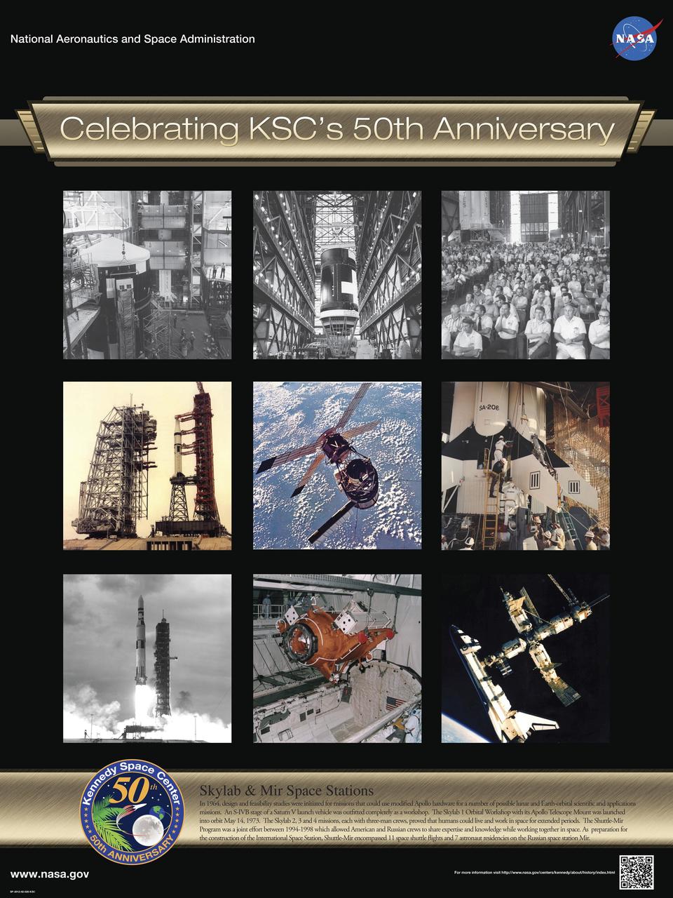
Skylab and Mir Space Stations: In 1964, design and feasibility studies were initiated for missions that could use modified Apollo hardware for a number of possible lunar and Earth-orbital scientific and applications missions. An S-IVB stage of a Saturn V launch vehicle was outfitted completely as a workshop. The Skylab 1 Orbital Workshop with its Apollo Telescope Mount was launched into orbit May 14, 1973. The Skylab 2, 3 and 4 missions, each with three-man crews, proved that humans could live and work in space for extended periods. The Shuttle-Mir Program was a joint effort between 1994-1998 which allowed American and Russian crews to share expertise and knowledge while working together in space. As preparation for the construction of the International Space Station, Shuttle-Mir encompassed 11 space shuttle flights and 7 astronaut residencies on the Russian space station Mir. Poster designed by Kennedy Space Center Graphics Department/Greg Lee. Credit: NASA

KENNEDY SPACE CENTER, FLA. -- Inside the Operations and Checkout Building high bay, Center Director Roy Bridges remarks on the accomplishment of the joint NASA/Boeing team in renovating an altitude chamber formerly used on the Apollo program. Project team members, management, media and onlookers are present for the ribbon cutting. The chamber was reactivated, after a 24-year hiatus, to perform leak tests on International Space Station pressurized modules at the launch site. Originally, two chambers were built to test the Apollo command and lunar service modules. They were last used in 1975 during the Apollo-Soyuz Test Project. After installation of new vacuum pumping equipment and controls, a new control room, and a new rotation handling fixture, the chamber again became operational in February 1999. The chamber, which is 33 feet in diameter and 50 feet tall, is constructed of stainless steel. The first module that will be tested for leaks is the U.S. Laboratory. No date has been determined for the test
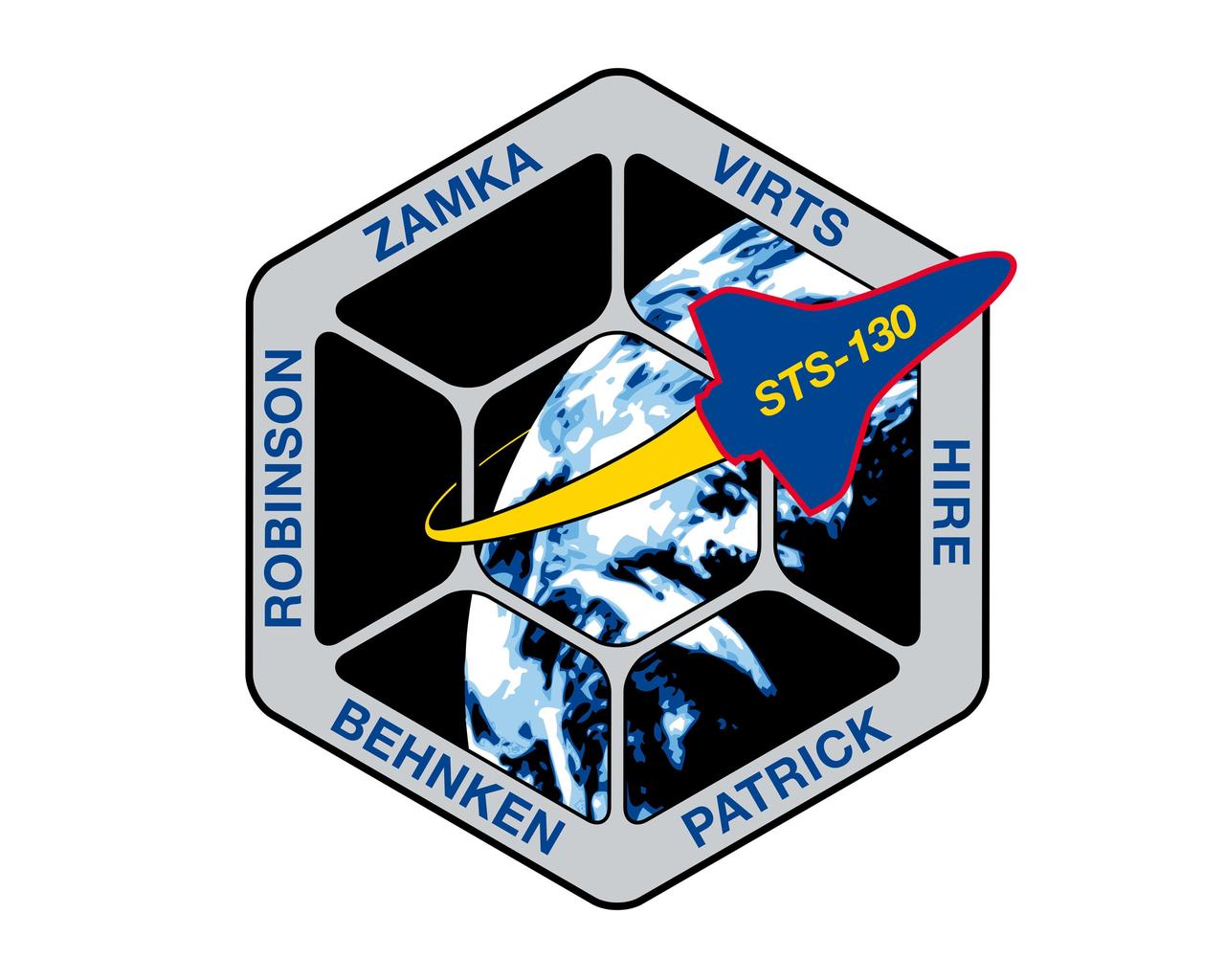
JOHNSON SPACE CENTER, Houston - STS130-S-001 - The STS-130 patch was designed by the crew to reflect both the objectives of the mission and its place in the history of human spaceflight. The main goal of the mission is to deliver Node 3 and the Cupola to the International Space Station (ISS). Node 3, named "Tranquility," will contain life support systems enabling continued human presence in orbit aboard the ISS. The shape of the patch represents the Cupola, which is the windowed robotics viewing station, from which astronauts will have the opportunity not only to monitor a variety of ISS operations, but also to study our home planet. The image of Earth depicted in the patch is the first photograph of the Earth taken from the moon by Lunar Orbiter I on August 23, 1966. As both a past and a future destination for explorers from the planet Earth, the moon is thus represented symbolically in the STS-130 patch. The Space Shuttle Endeavour is pictured approaching the ISS, symbolizing the Space Shuttle's role as the prime construction vehicle for the ISS. The NASA insignia design for shuttle flights is reserved for use by the astronauts and for other official use as the NASA Administrator may authorize. Public availability has been approved only in the form of illustrations by the various news media. When and if there is any change in this policy, which we do not anticipate, it will be publicly announced.
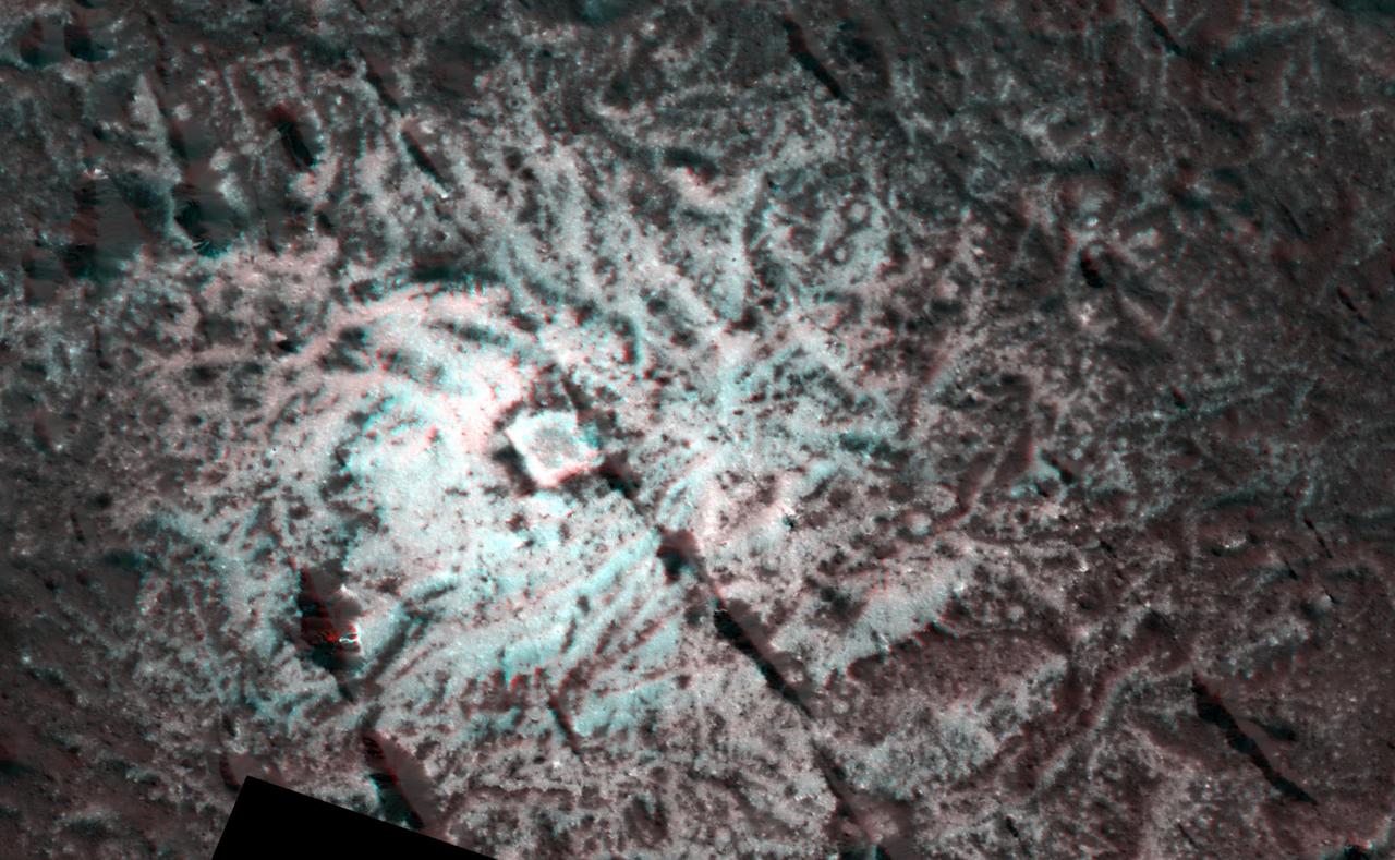
The Dawn spacecraft captured these stereo images of Occator Crater on the dwarf planet Ceres in 2018. Framing camera images were used to construct this anaglyph view (which requires red-blue stereo glasses for viewing) of part of the southeastern floor of the crater. This area is approximately 3 miles (5 kilometers) wide and is entirely within the large impact melt deposit formed there during the impact process. The low bright mounds and pits were probably formed by brine that moved to the surface to form surface vents and surface domes during freezing. The spatial resolution of the stereo images is about 11 feet (3.5 meters) per pixel. Occator crater, named after the Roman god of the agricultural practice of harrowing, is about 57 miles (92 kilometers) in diameter. The conclusion of Dawn's mission operations was Oct. 31, 2018, when the spacecraft depleted its hydrazine used for attitude control. This image was produced by Dr. Paul Schenk at the Lunar and Planetary Institute in Houston. https://photojournal.jpl.nasa.gov/catalog/PIA24062
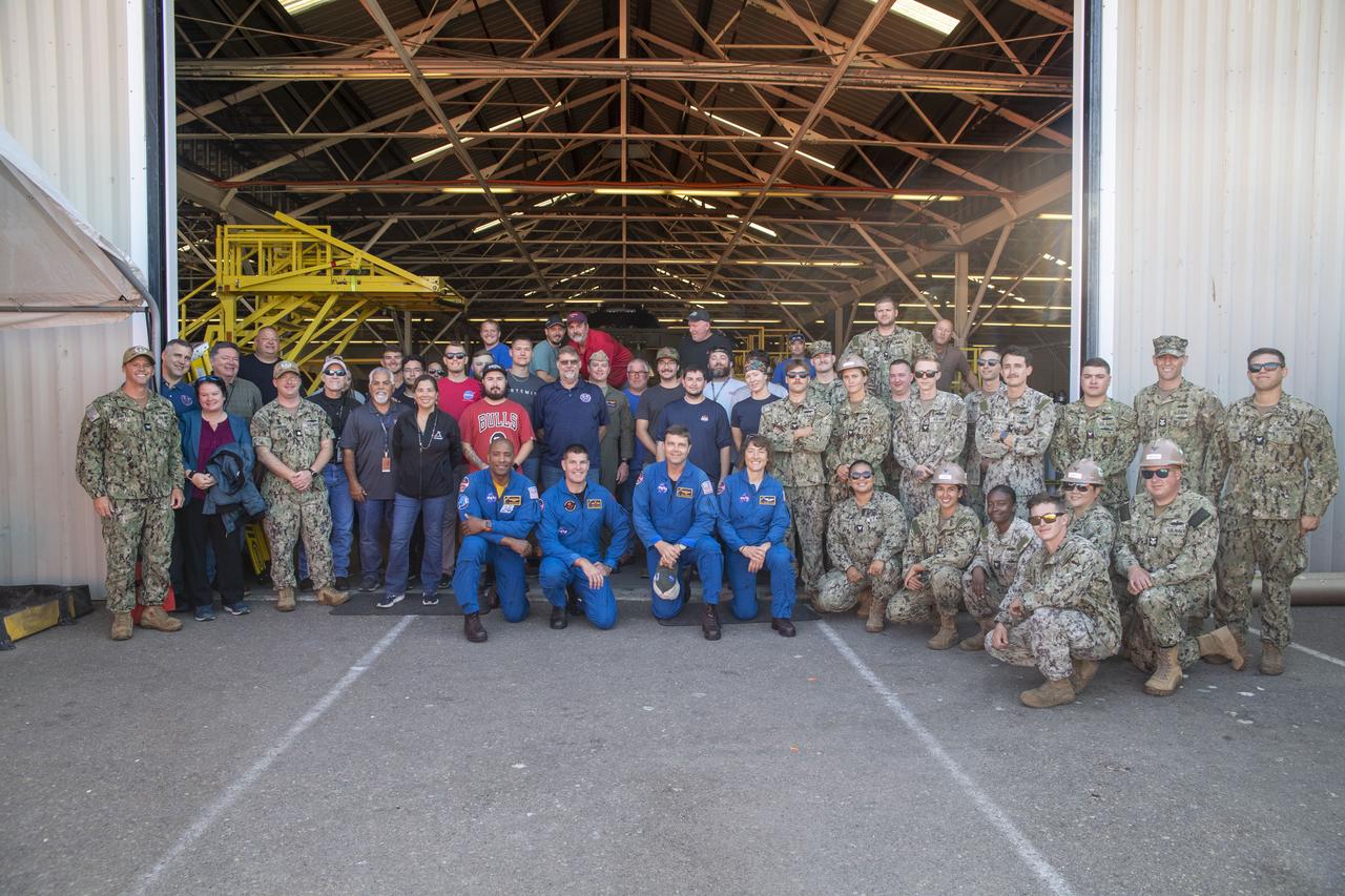
From left to right, NASA astronaut Victor Glover, Canadian Space Agency astronaut Jeremy Hansen, NASA astronauts Reid Wiseman and Christina Hammock Koch, pose with teams from NASA’s Exploration Ground Systems Program and sailors from the U.S. Navy assigned to Amphibious Construction Battalion 1 during a tour of Defense Distribution Depot Center in San Diego, California, on July 19, 2023. The depot is currently being used by NASA to house the Vehicle Advanced Demonstrator for Emergency Recovery, “VADER”, a replica of the space capsule. In preparation for NASA's Artemis II crewed mission, which will send four astronauts in Orion beyond the Moon, NASA and the U.S. Navy will conduct a series of tests to demonstrate and evaluate the processes, procedures, and hardware used in recovery operations for crewed lunar missions. The approximately 10-day flight of Artemis II will test NASA's foundational human deep space exploration capabilities, the Space Launch System rocket and Orion spacecraft, for the first time with astronauts and will pave the way to establishing a long-term presence at the Moon for science and exploration through Artemis.
STS130-S-001 (September 2009) --- The STS-130 patch was designed by the crew to reflect both the objectives of the mission and its place in the history of human spaceflight. The main goal of the mission is to deliver Node 3 and the Cupola to the International Space Station (ISS). Node 3, named ?Tranquility,? will contain life support systems enabling continued human presence in orbit aboard the ISS. The shape of the patch represents the Cupola, which is the windowed robotics viewing station, from which astronauts will have the opportunity not only to monitor a variety of ISS operations, but also to study our home planet. The image of Earth depicted in the patch is the first photograph of Earth taken from the moon by Lunar Orbiter I on Aug. 23, 1966. As both a past and a future destination for explorers from planet Earth, the moon is thus represented symbolically in the STS-130 patch. The space shuttle Endeavour is pictured approaching the ISS, symbolizing the space shuttle's role as the prime construction vehicle for the ISS. The NASA insignia design for space shuttle flights is reserved for use by the astronauts and for other official use as the NASA Administrator may authorize. Public availability has been approved only in the forms of illustrations by the various news media. When and if there is any change in this policy, which is not anticipated, the change will be publicly announced. Photo credit: NASA
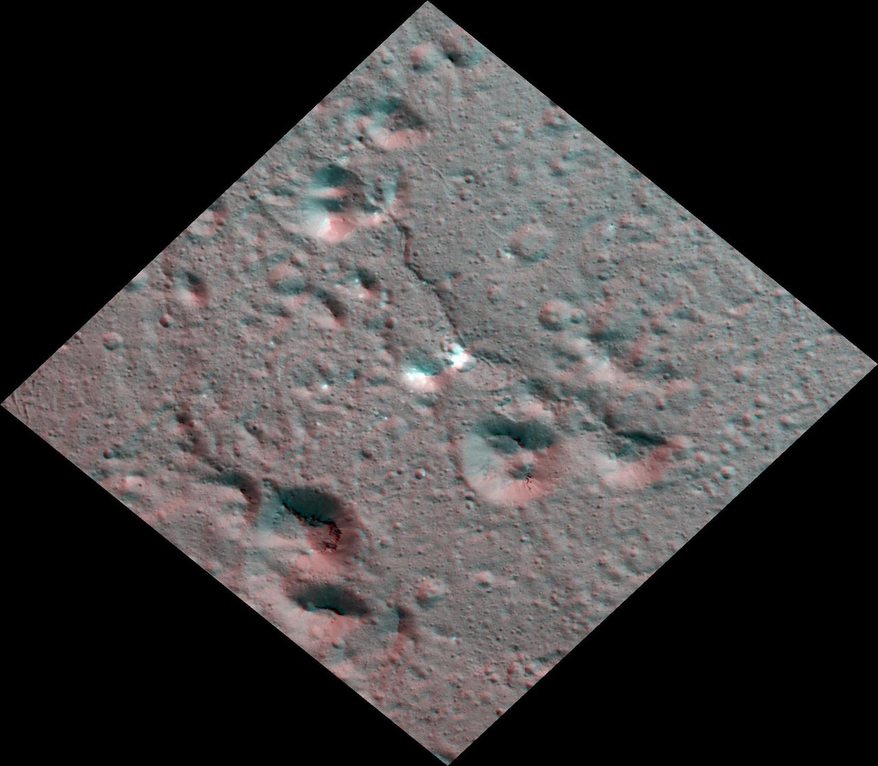
The Dawn spacecraft captured these stereo images of Occator Crater on the dwarf planet Ceres in 2018. This view is part of a mosaic of about 50 framing camera images used to construct this anaglyph view (which requires red-blue stereo glasses for viewing) of part of the eastern floor of the crater. This area is approximately 5 miles (8.5 kilometers) wide and features bright carbonate deposits of the Vinalia Faculae formation on top of the ropey textured lobate floor impact melt deposit. Stereo views of Vinalia Faculae illustrate the complex relationship between the thin carbonates and the underlying impact deposits. The spatial resolution of the stereo images is about 11 feet (3.5 meters) per pixel. Occator crater, named after the Roman god of the agricultural practice of harrowing, is about 57 miles (92 kilometers) in diameter. The conclusion of Dawn's mission operations was Oct. 31, 2018, when the spacecraft depleted its hydrazine used for attitude control. This image was produced by Dr. Paul Schenk at the Lunar and Planetary Institute in Houston. https://photojournal.jpl.nasa.gov/catalog/PIA24063
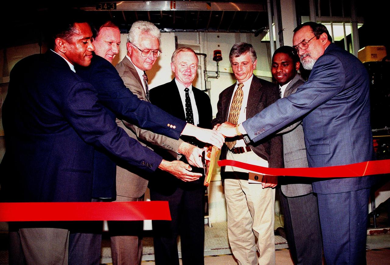
KENNEDY SPACE CENTER, FLA. -- Cutting a red ribbon for the unveiling of a newly renovated altitude chamber are (left to right) Tommy Mack, project manager, NASA; Steve Francois, director, Space Station and Shuttle Payloads; Sterling Walker, director, Engineering Development; Roy Bridges, director, Kennedy Space Center; Jay Greene, International Space Station manager for Technical; Michael Terry, project manager, Boeing; and Terry Smith, director of Engineering, Boeing Space Coast Operations. The chamber was reactivated, after a 24-year hiatus, to perform leak tests on International Space Station pressurized modules at the launch site. Originally, two chambers were built to test the Apollo command and lunar service modules. They were last used in 1975 during the Apollo-Soyuz Test Project. After installation of new vacuum pumping equipment and controls, a new control room, and a new rotation handling fixture, the chamber again became operational in February 1999. The chamber, which is 33 feet in diameter and 50 feet tall, is constructed of stainless steel. The first module that will be tested for leaks is the U.S. Laboratory. No date has been determined for the test
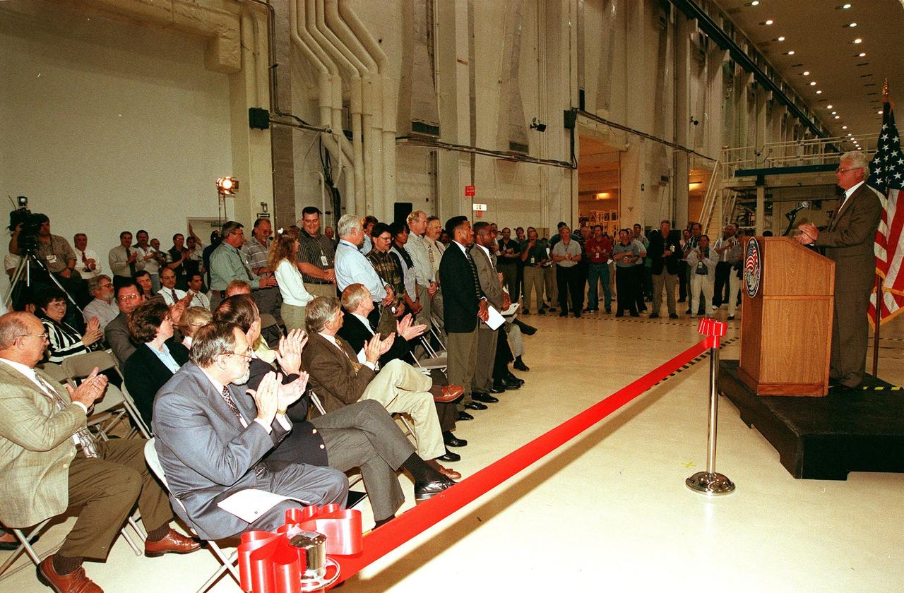
KENNEDY SPACE CENTER, FLA. -- At a ribbon-cutting ceremony inside the Operations and Checkout Building high bay, Sterling Walker, director of Engineering Development, introduces the project team members responsible for renovating an altitude chamber formerly used on the Apollo program. In addition, management, media and onlookers are present for the ceremony. Seated in the front row left are (left to right) Terry Smith, director of Engineering, Boeing Space Coast Operations; Steve Francois, director, Space Station and Shuttle Payloads; Jay Greene, International Space Station manager for Technical; and Roy Bridges, center director. The chamber was reactivated, after a 24-year hiatus, to perform leak tests on International Space Station pressurized modules at the launch site. Originally, two chambers were built to test the Apollo command and lunar service modules. They were last used in 1975 during the Apollo-Soyuz Test Project. After installation of new vacuum pumping equipment and controls, a new control room, and a new rotation handling fixture, the chamber again became operational in February 1999. The chamber, which is 33 feet in diameter and 50 feet tall, is constructed of stainless steel. The first module that will be tested for leaks is the U.S. Laboratory. No date has been determined for the test
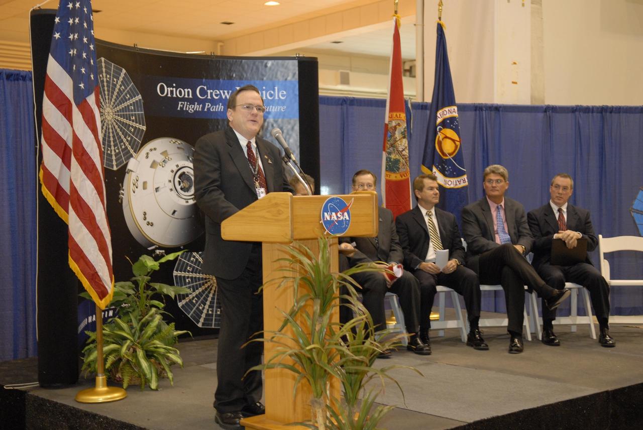
KENNEDY SPACE CENTER, FLA. -- Skip Hatfield, Orion Project manager, addresses guests and attendees in the Operations and Checkout (O&C) Building high bay in the ceremony commemorating the bay's transition for use by the Constellation Program. Seated on the dais at right are representatives from NASA, Lockheed Martin, Space Florida and the state of Florida: Russell Romanella, director of the International Space Station/Payload Processing Directorate at Kennedy Space Center, Cleon Lacefield, Lockheed Martin program manager; Thad Altman, representative of the State of Florida; Bill Parsons, director of Kennedy Space Center; and Steve Koller, executive director of Space Florida. Originally built to process space vehicles in the Apollo era, the O&C Building will serve as the final assembly facility for the Orion crew exploration vehicle. Orion, America's human spaceflight vehicle of the future, will be capable of transporting four crewmembers for lunar missions and later will support crew transfers for Mars missions. Each Orion spacecraft also may be used to support up to six crewmembers to the International Space Station after the space shuttle is retired in 2010. Design, development and construction of Orion's components will be performed by Lockheed Martin for NASA at facilities throughout the country. Photo credit: NASA/Kim Shiflett
KENNEDY SPACE CENTER, FLA. -- Russell Romanella, director of the International Space Station/Payload Processing Directorate at Kennedy Space Center, addresses guests and attendees in the Operations and Checkout (O&C) Building high bay in the ceremony commemorating the bay's transition for use by the Constellation Program. Seated on the dais at right are Cleon Lacefield, Lockheed Martin program manager; Thad Altman, representative of the State of Florida; Bill Parsons, Kennedy Space Center director; Steve Koller, executive director of Space Florida; and Skip Hatfield, Orion Project manager. Originally built to process space vehicles in the Apollo era, the O&C Building will serve as the final assembly facility for the Orion crew exploration vehicle. Orion, America's human spaceflight vehicle of the future, will be capable of transporting four crewmembers for lunar missions and later will support crew transfers for Mars missions. Each Orion spacecraft also may be used to support up to six crewmembers to the International Space Station after the space shuttle is retired in 2010. Design, development and construction of Orion's components will be performed by Lockheed Martin for NASA at facilities throughout the country. Photo credit: NASA/Kim Shiflett
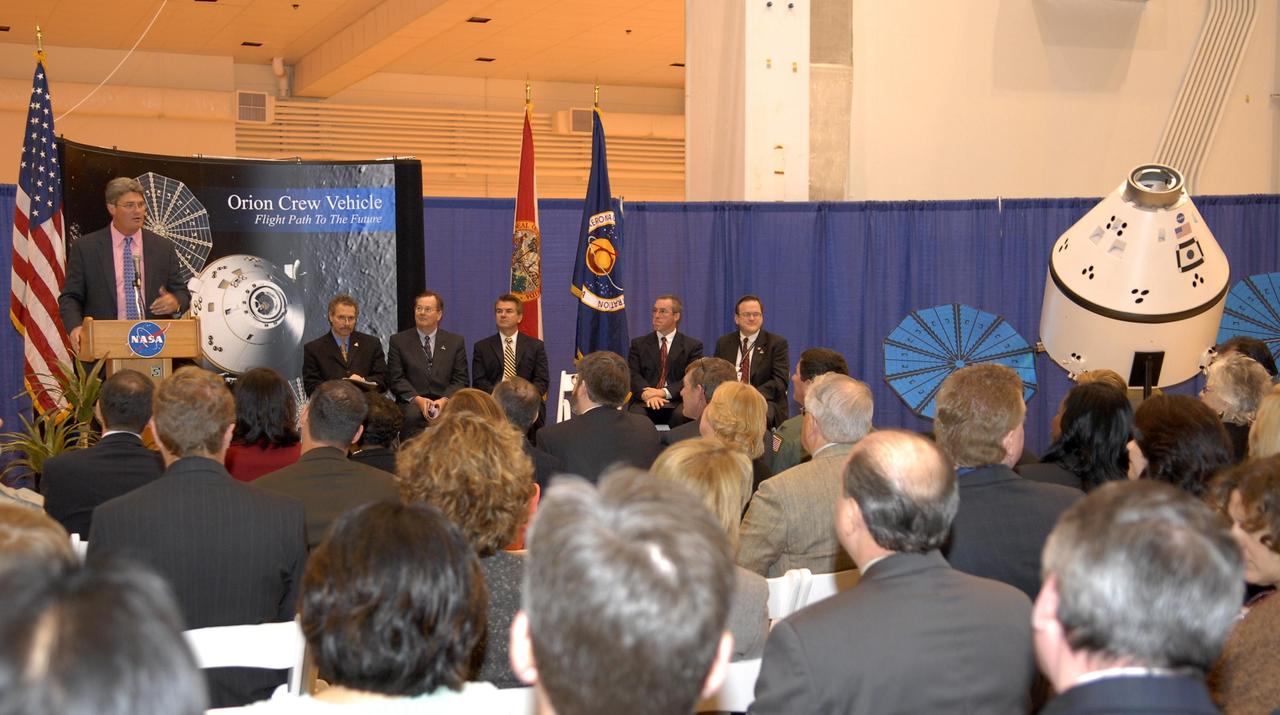
KENNEDY SPACE CENTER, FLA. -- Kennedy Space Center Director Bill Parsons addresses guests and attendees in the Operations and Checkout (O&C) Building high bay in the ceremony commemorating the bay's transition for use by the Constellation Program. Representatives from NASA, Lockheed Martin, Space Florida and the state of Florida are seated at right: Russell Romanella, director of the International Space Station/Payload Processing Directorate at Kennedy Space Center, Cleon Lacefield, Lockheed Martin program manager; Thad Altman, representative of the State of Florida; Steve Koller, executive director of Space Florida; and Skip Hatfield, Orion Project manager. Originally built to process space vehicles in the Apollo era, the O&C Building will serve as the final assembly facility for the Orion crew exploration vehicle. Orion, America's human spaceflight vehicle of the future, will be capable of transporting four crewmembers for lunar missions and later will support crew transfers for Mars missions. Each Orion spacecraft also may be used to support up to six crewmembers to the International Space Station after the space shuttle is retired in 2010. Design, development and construction of Orion's components will be performed by Lockheed Martin for NASA at facilities throughout the country. Photo credit: NASA/Kim Shiflett
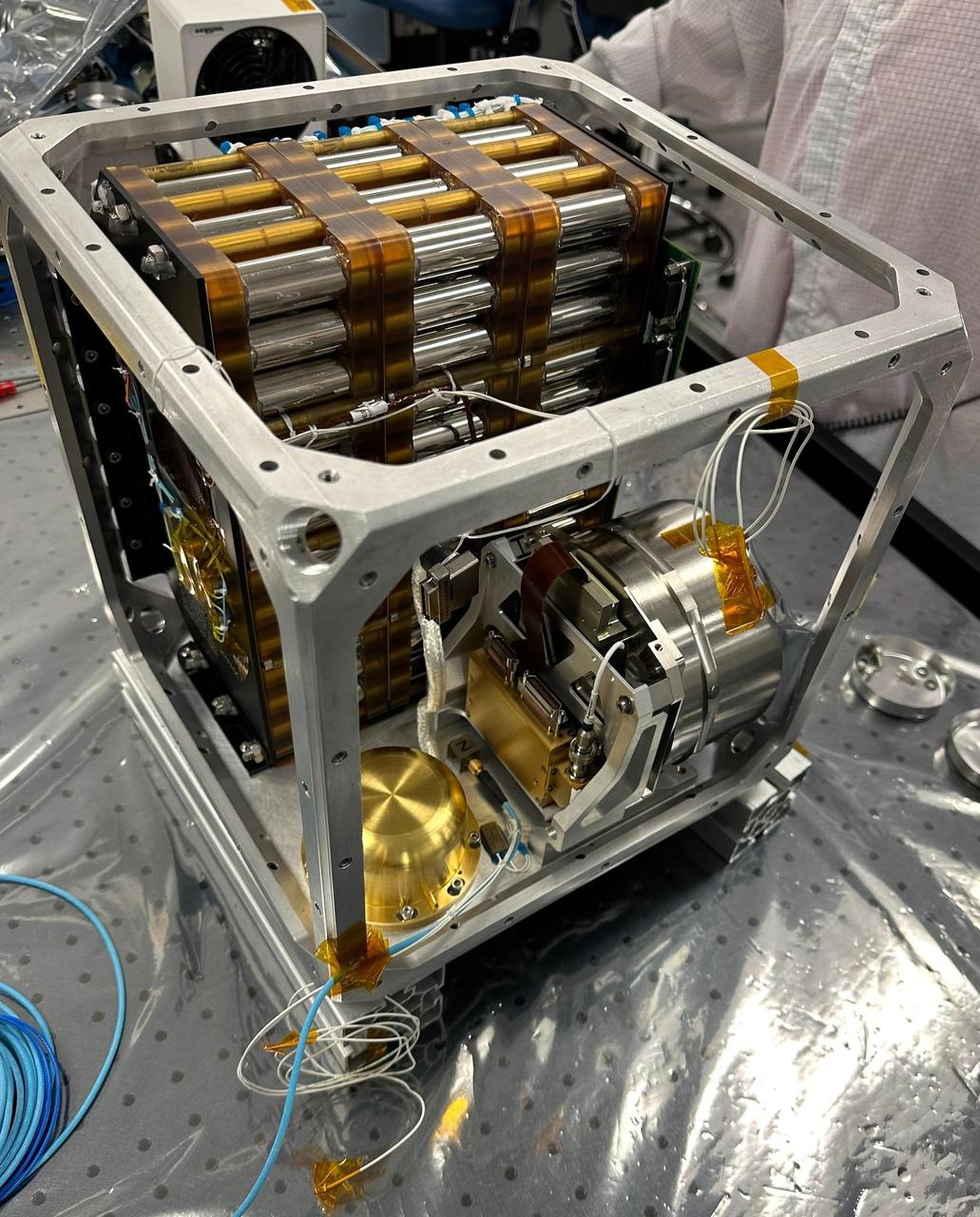
NASA's Farside Seismic Suite (FSS) is assembled in a clean room at the agency's Jet Propulsion Laboratory in Southern California in November 2023. Two sensitive seismometers packaged in the suite's cube-within-a-cube structure will gather NASA's first seismic data from the Moon in nearly 50 years and take the first-ever seismic measurements from the Moon's far side. FSS will operate continuously for at least 4½ months, working through the long, cold lunar nights. Seen here is the inner cube structure, with the suite's large battery at rear. The gold, puck-shaped device at left is the Short Period sensor, or SP, which measures motion in three directions using sensors etched into a trio of square silicon chips, each about 1 inch (25 millimeters) wide. At right, within the silver cylindrical enclosure, is the Very Broadband seismometer, or VBB, the most sensitive seismometer ever built for use in space exploration. It can detect ground motions smaller than the size of a single hydrogen atom, measuring up-and-down movement using a pendulum held in place by a spring. Constructed as a backup instrument (a "flight spare") for NASA's InSight Mars lander by the French space agency, CNES (Centre National d'Études Spatiales), the VBB was slightly modified and packaged in a new enclosure for lunar use. The suite's computer and electronics are packed alongside the battery and seismometers. After being encased in insulation, this inner cube was suspended within a protective outer cube, which was in turn covered with a shiny insulating blanket. https://photojournal.jpl.nasa.gov/catalog/PIA26300
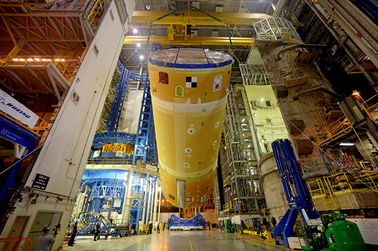
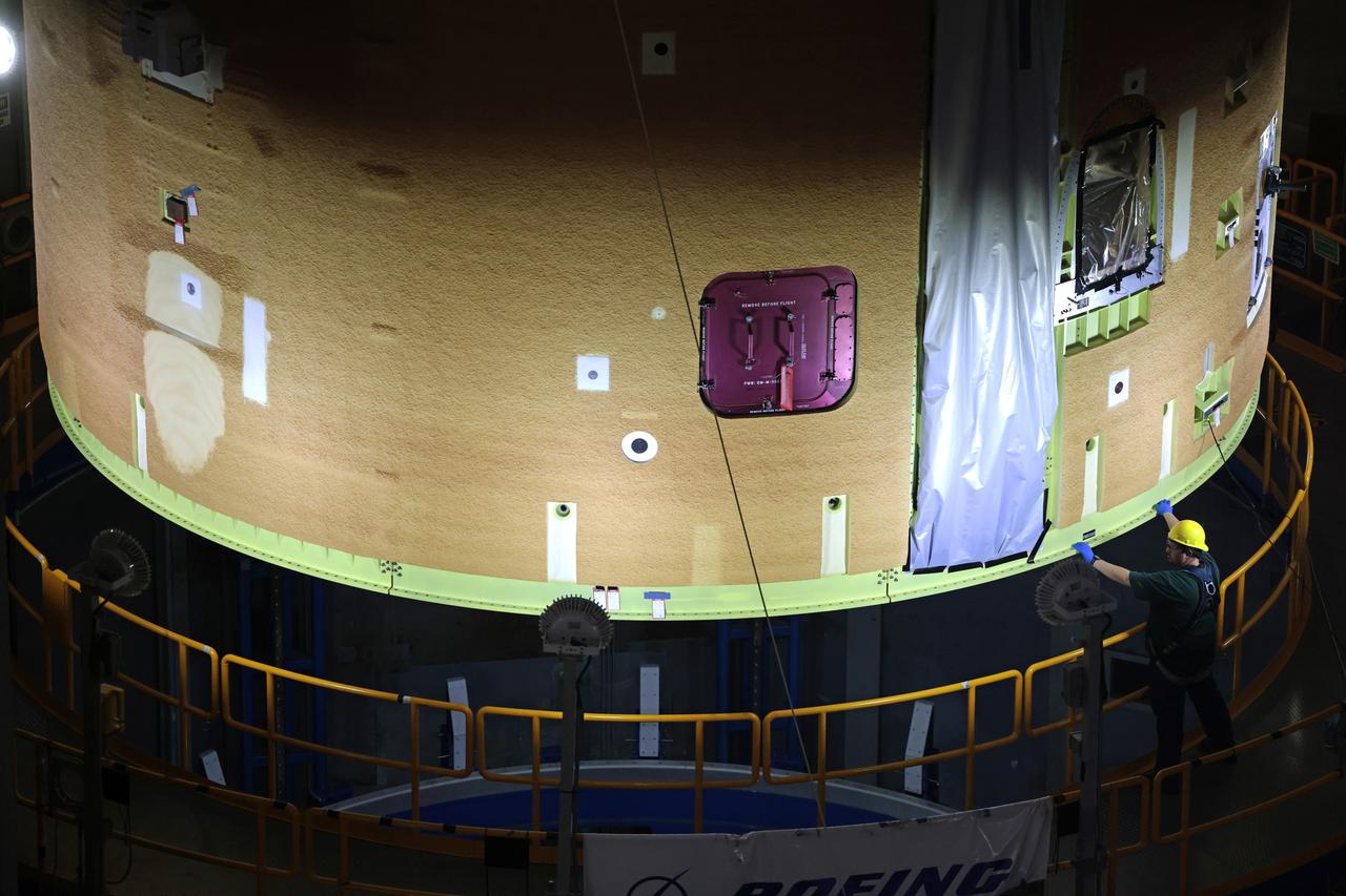
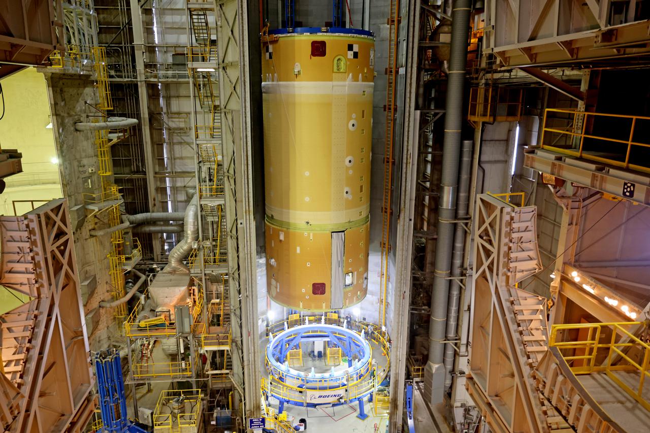
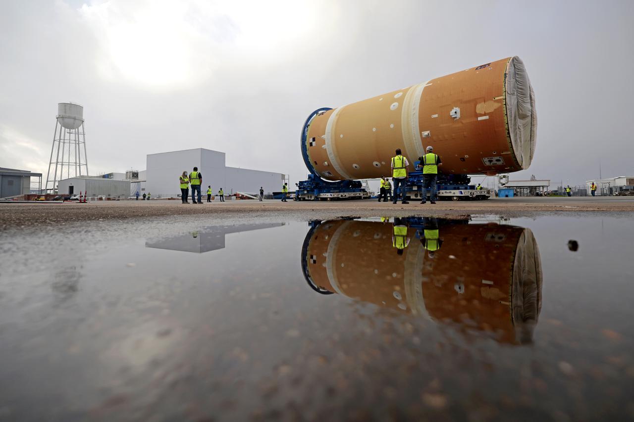
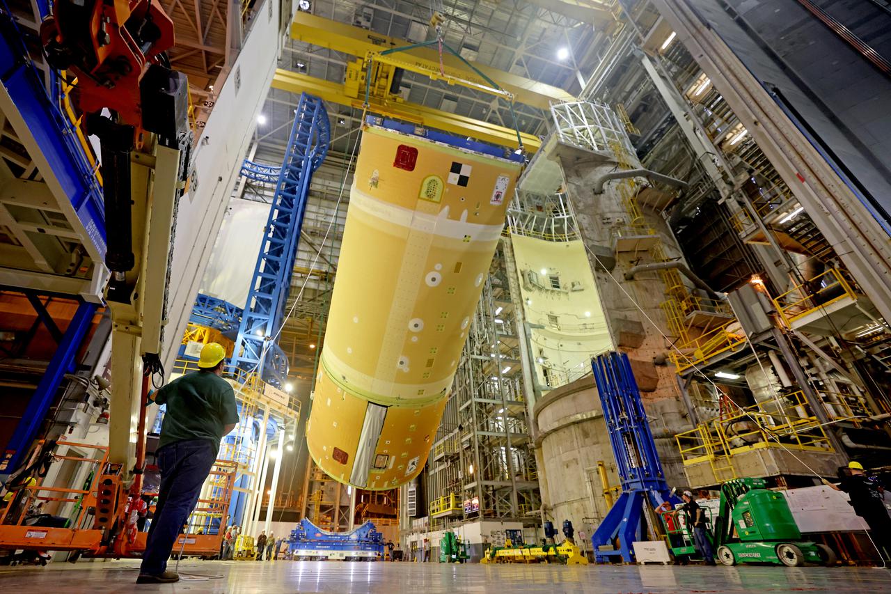
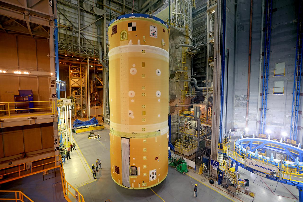
NASA has completed assembly of the upper, or forward, part of the core stage for the Space Launch System (SLS) rocket that will send the Artemis II crew on their lunar mission. Boeing, the lead core stage contractor, completed joining the forward part of the rocket, and then lifted it out of the assembly structure at NASA’s Michoud Assembly Facility in New Orleans. To construct this part of the core stage, the team first stacked three major parts of the stage—the forward skirt, the liquid oxygen tank, and the intertank. The forward skirt sits atop the rocket’s core stage, and it and the intertank are outfitted with the rocket’s flight computers and avionics systems that control SLS during launch and ascent. The liquid oxygen tank holds 196,000 gallons of liquid oxygen cooled to minus 297 degrees Fahrenheit. The entire upper part of the stage is around 66-feet tall. The fully-assembled, 212-foot-tall rocket stage consists of five hardware elements. As the team lifted it out of the assembly area, they completed a breakover maneuver, to put the forward assembly in a horizontal position. Then, they moved it to final assembly where the Artemis II liquid hydrogen tank is also undergoing outfitting. Here, teams will connect the liquid hydrogen tank to the upper part of the rocket and complete assembly of four of the five core stage parts. The last piece to be added will be the engine section, which is currently in a separate assembly area being outfitted with propulsion systems that connect to the engines. Image credit: NASA/Michael DeMocker
NASA has completed assembly of the upper, or forward, part of the core stage for the Space Launch System (SLS) rocket that will send the Artemis II crew on their lunar mission. Boeing, the lead core stage contractor, completed joining the forward part of the rocket, and then lifted it out of the assembly structure at NASA’s Michoud Assembly Facility in New Orleans. To construct this part of the core stage, the team first stacked three major parts of the stage—the forward skirt, the liquid oxygen tank, and the intertank. The forward skirt sits atop the rocket’s core stage, and it and the intertank are outfitted with the rocket’s flight computers and avionics systems that control SLS during launch and ascent. The liquid oxygen tank holds 196,000 gallons of liquid oxygen cooled to minus 297 degrees Fahrenheit. The entire upper part of the stage is around 66-feet tall. The fully-assembled, 212-foot-tall rocket stage consists of five hardware elements. As the team lifted it out of the assembly area, they completed a breakover maneuver, to put the forward assembly in a horizontal position. Then, they moved it to final assembly where the Artemis II liquid hydrogen tank is also undergoing outfitting. Here, teams will connect the liquid hydrogen tank to the upper part of the rocket and complete assembly of four of the five core stage parts. The last piece to be added will be the engine section, which is currently in a separate assembly area being outfitted with propulsion systems that connect to the engines. Image credit: NASA/Michael DeMocker
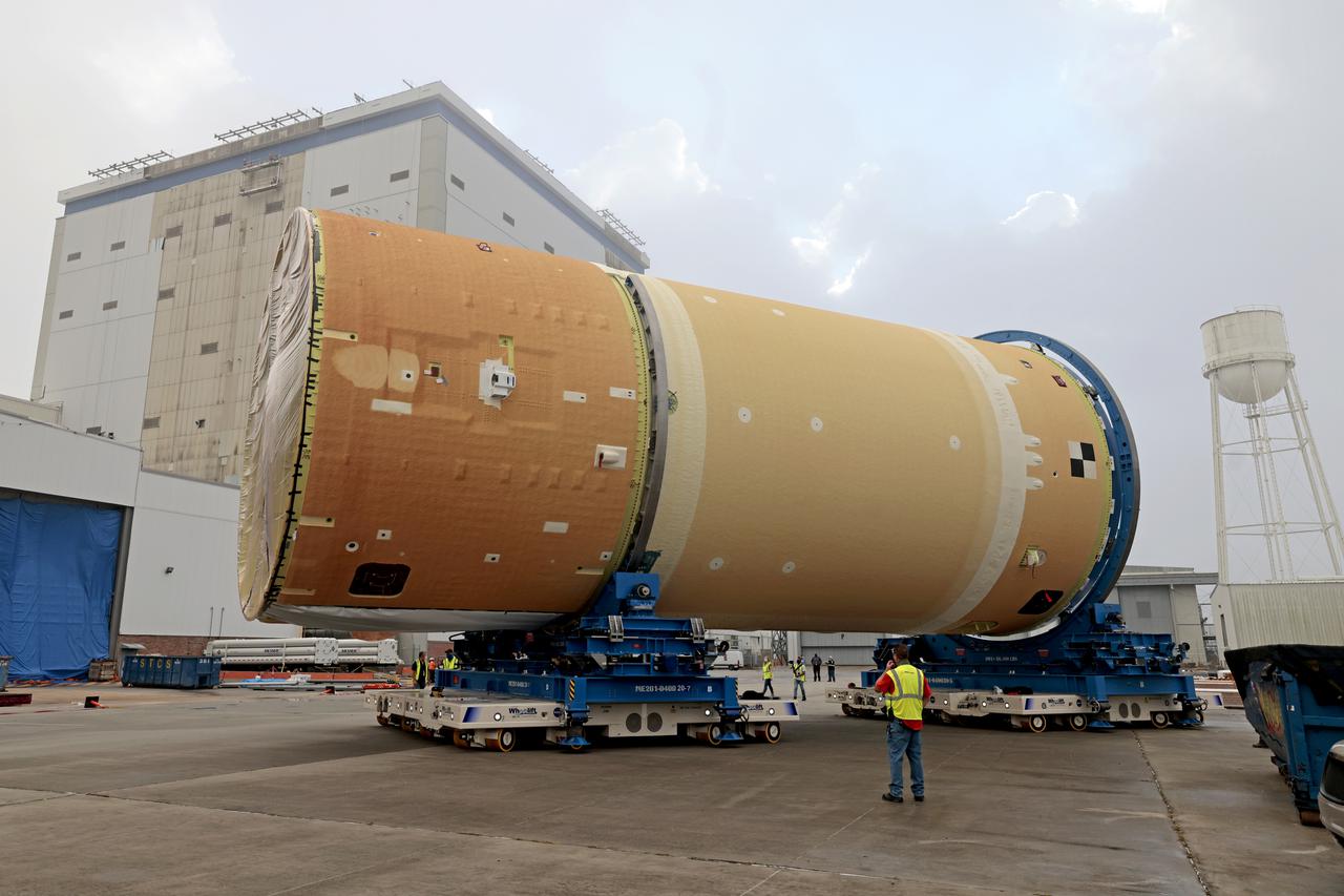
NASA has completed assembly of the upper, or forward, part of the core stage for the Space Launch System (SLS) rocket that will send the Artemis II crew on their lunar mission. Boeing, the lead core stage contractor, completed joining the forward part of the rocket, and then lifted it out of the assembly structure at NASA’s Michoud Assembly Facility in New Orleans. To construct this part of the core stage, the team first stacked three major parts of the stage—the forward skirt, the liquid oxygen tank, and the intertank. The forward skirt sits atop the rocket’s core stage, and it and the intertank are outfitted with the rocket’s flight computers and avionics systems that control SLS during launch and ascent. The liquid oxygen tank holds 196,000 gallons of liquid oxygen cooled to minus 297 degrees Fahrenheit. The entire upper part of the stage is around 66-feet tall. The fully-assembled, 212-foot-tall rocket stage consists of five hardware elements. As the team lifted it out of the assembly area, they completed a breakover maneuver, to put the forward assembly in a horizontal position. Then, they moved it to final assembly where the Artemis II liquid hydrogen tank is also undergoing outfitting. Here, teams will connect the liquid hydrogen tank to the upper part of the rocket and complete assembly of four of the five core stage parts. The last piece to be added will be the engine section, which is currently in a separate assembly area being outfitted with propulsion systems that connect to the engines. Image credit: NASA/Michael DeMocker
NASA has completed assembly of the upper, or forward, part of the core stage for the Space Launch System (SLS) rocket that will send the Artemis II crew on their lunar mission. Boeing, the lead core stage contractor, completed joining the forward part of the rocket, and then lifted it out of the assembly structure at NASA’s Michoud Assembly Facility in New Orleans. To construct this part of the core stage, the team first stacked three major parts of the stage—the forward skirt, the liquid oxygen tank, and the intertank. The forward skirt sits atop the rocket’s core stage, and it and the intertank are outfitted with the rocket’s flight computers and avionics systems that control SLS during launch and ascent. The liquid oxygen tank holds 196,000 gallons of liquid oxygen cooled to minus 297 degrees Fahrenheit. The entire upper part of the stage is around 66-feet tall. The fully-assembled, 212-foot-tall rocket stage consists of five hardware elements. As the team lifted it out of the assembly area, they completed a breakover maneuver, to put the forward assembly in a horizontal position. Then, they moved it to final assembly where the Artemis II liquid hydrogen tank is also undergoing outfitting. Here, teams will connect the liquid hydrogen tank to the upper part of the rocket and complete assembly of four of the five core stage parts. The last piece to be added will be the engine section, which is currently in a separate assembly area being outfitted with propulsion systems that connect to the engines. Image credit: NASA/Michael DeMocker
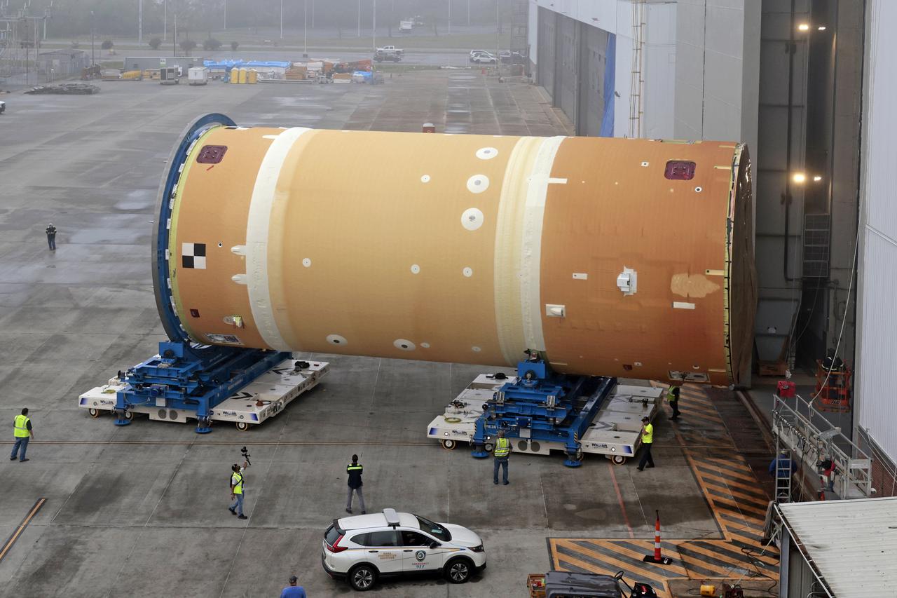
NASA has completed assembly of the upper, or forward, part of the core stage for the Space Launch System (SLS) rocket that will send the Artemis II crew on their lunar mission. Boeing, the lead core stage contractor, completed joining the forward part of the rocket, and then lifted it out of the assembly structure at NASA’s Michoud Assembly Facility in New Orleans. To construct this part of the core stage, the team first stacked three major parts of the stage—the forward skirt, the liquid oxygen tank, and the intertank. The forward skirt sits atop the rocket’s core stage, and it and the intertank are outfitted with the rocket’s flight computers and avionics systems that control SLS during launch and ascent. The liquid oxygen tank holds 196,000 gallons of liquid oxygen cooled to minus 297 degrees Fahrenheit. The entire upper part of the stage is around 66-feet tall. The fully-assembled, 212-foot-tall rocket stage consists of five hardware elements. As the team lifted it out of the assembly area, they completed a breakover maneuver, to put the forward assembly in a horizontal position. Then, they moved it to final assembly where the Artemis II liquid hydrogen tank is also undergoing outfitting. Here, teams will connect the liquid hydrogen tank to the upper part of the rocket and complete assembly of four of the five core stage parts. The last piece to be added will be the engine section, which is currently in a separate assembly area being outfitted with propulsion systems that connect to the engines. Image credit: NASA/Michael DeMocker
NASA has completed assembly of the upper, or forward, part of the core stage for the Space Launch System (SLS) rocket that will send the Artemis II crew on their lunar mission. Boeing, the lead core stage contractor, completed joining the forward part of the rocket, and then lifted it out of the assembly structure at NASA’s Michoud Assembly Facility in New Orleans. To construct this part of the core stage, the team first stacked three major parts of the stage—the forward skirt, the liquid oxygen tank, and the intertank. The forward skirt sits atop the rocket’s core stage, and it and the intertank are outfitted with the rocket’s flight computers and avionics systems that control SLS during launch and ascent. The liquid oxygen tank holds 196,000 gallons of liquid oxygen cooled to minus 297 degrees Fahrenheit. The entire upper part of the stage is around 66-feet tall. The fully-assembled, 212-foot-tall rocket stage consists of five hardware elements. As the team lifted it out of the assembly area, they completed a breakover maneuver, to put the forward assembly in a horizontal position. Then, they moved it to final assembly where the Artemis II liquid hydrogen tank is also undergoing outfitting. Here, teams will connect the liquid hydrogen tank to the upper part of the rocket and complete assembly of four of the five core stage parts. The last piece to be added will be the engine section, which is currently in a separate assembly area being outfitted with propulsion systems that connect to the engines. Image credit: NASA/Michael DeMocker
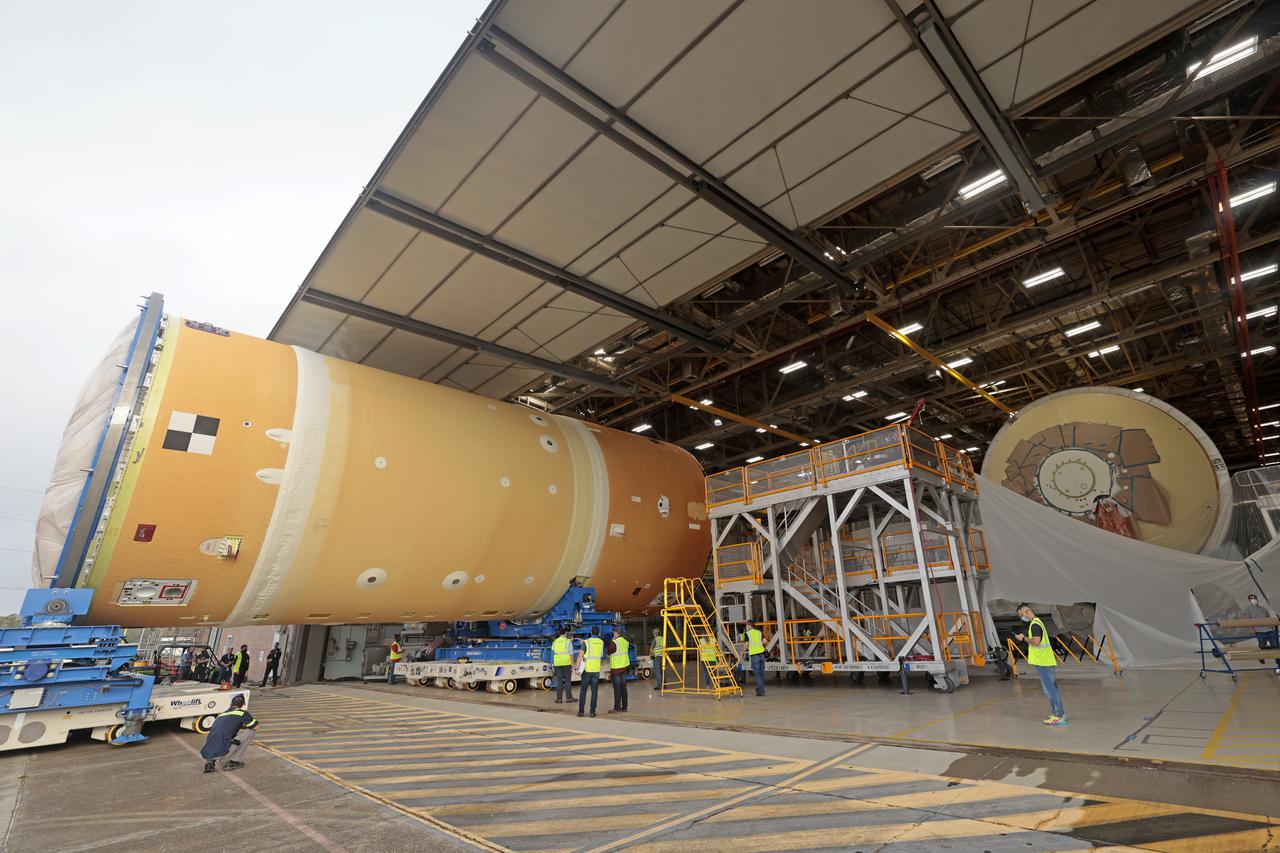
NASA has completed assembly of the upper, or forward, part of the core stage for the Space Launch System (SLS) rocket that will send the Artemis II crew on their lunar mission. Boeing, the lead core stage contractor, completed joining the forward part of the rocket, and then lifted it out of the assembly structure at NASA’s Michoud Assembly Facility in New Orleans. To construct this part of the core stage, the team first stacked three major parts of the stage—the forward skirt, the liquid oxygen tank, and the intertank. The forward skirt sits atop the rocket’s core stage, and it and the intertank are outfitted with the rocket’s flight computers and avionics systems that control SLS during launch and ascent. The liquid oxygen tank holds 196,000 gallons of liquid oxygen cooled to minus 297 degrees Fahrenheit. The entire upper part of the stage is around 66-feet tall. The fully-assembled, 212-foot-tall rocket stage consists of five hardware elements. As the team lifted it out of the assembly area, they completed a breakover maneuver, to put the forward assembly in a horizontal position. Then, they moved it to final assembly where the Artemis II liquid hydrogen tank is also undergoing outfitting. Here, teams will connect the liquid hydrogen tank to the upper part of the rocket and complete assembly of four of the five core stage parts. The last piece to be added will be the engine section, which is currently in a separate assembly area being outfitted with propulsion systems that connect to the engines. Image credit: NASA/Michael DeMocker

KENNEDY SPACE CENTER, FLA. -- Representatives from NASA, Lockheed Martin, Space Florida and the state of Florida are seated on stage at a ceremony to commemorate the transition of the historic Operations and Checkout (O&C) Building high bay for use by the Constellation Program. From left are Cleon Lacefield, Lockheed Martin program manager; Thad Altman, representative of the State of Florida; Bill Parsons, Kennedy Space Center director; Steve Koller, executive director of Space Florida; and Skip Hatfield, Orion Project manager. Representatives from NASA, Lockheed Martin, Space Florida and the state of Florida are seated on stage at a ceremony to commemorate the transition of the historic Operations and Checkout (O&C) Building high bay for use by the Constellation Program. From left are Cleon Lacefield, Lockheed Martin program manager; Thad Altman, representative of the State of Florida; Bill Parsons, Kennedy Space Center director; Steve Koller, executive director of Space Florida; and Skip Hatfield, Orion Project manager. Originally built to process space vehicles in the Apollo era, the O&C Building will serve as the final assembly facility for the Orion crew exploration vehicle. Orion, America's human spaceflight vehicle of the future, will be capable of transporting four crewmembers for lunar missions and later will support crew transfers for Mars missions. Each Orion spacecraft also may be used to support up to six crewmembers to the International Space Station after the space shuttle is retired in 2010. Design, development and construction of Orion's components will be performed by Lockheed Martin for NASA at facilities throughout the country. Photo credit: NASA/Kim Shiflett
NASA has completed assembly of the upper, or forward, part of the core stage for the Space Launch System (SLS) rocket that will send the Artemis II crew on their lunar mission. Boeing, the lead core stage contractor, completed joining the forward part of the rocket, and then lifted it out of the assembly structure at NASA’s Michoud Assembly Facility in New Orleans. To construct this part of the core stage, the team first stacked three major parts of the stage—the forward skirt, the liquid oxygen tank, and the intertank. The forward skirt sits atop the rocket’s core stage, and it and the intertank are outfitted with the rocket’s flight computers and avionics systems that control SLS during launch and ascent. The liquid oxygen tank holds 196,000 gallons of liquid oxygen cooled to minus 297 degrees Fahrenheit. The entire upper part of the stage is around 66-feet tall. The fully-assembled, 212-foot-tall rocket stage consists of five hardware elements. As the team lifted it out of the assembly area, they completed a breakover maneuver, to put the forward assembly in a horizontal position. Then, they moved it to final assembly where the Artemis II liquid hydrogen tank is also undergoing outfitting. Here, teams will connect the liquid hydrogen tank to the upper part of the rocket and complete assembly of four of the five core stage parts. The last piece to be added will be the engine section, which is currently in a separate assembly area being outfitted with propulsion systems that connect to the engines. Image credit: NASA/Michael DeMocker
NASA has completed assembly of the upper, or forward, part of the core stage for the Space Launch System (SLS) rocket that will send the Artemis II crew on their lunar mission. Boeing, the lead core stage contractor, completed joining the forward part of the rocket, and then lifted it out of the assembly structure at NASA’s Michoud Assembly Facility in New Orleans. To construct this part of the core stage, the team first stacked three major parts of the stage—the forward skirt, the liquid oxygen tank, and the intertank. The forward skirt sits atop the rocket’s core stage, and it and the intertank are outfitted with the rocket’s flight computers and avionics systems that control SLS during launch and ascent. The liquid oxygen tank holds 196,000 gallons of liquid oxygen cooled to minus 297 degrees Fahrenheit. The entire upper part of the stage is around 66-feet tall. The fully-assembled, 212-foot-tall rocket stage consists of five hardware elements. As the team lifted it out of the assembly area, they completed a breakover maneuver, to put the forward assembly in a horizontal position. Then, they moved it to final assembly where the Artemis II liquid hydrogen tank is also undergoing outfitting. Here, teams will connect the liquid hydrogen tank to the upper part of the rocket and complete assembly of four of the five core stage parts. The last piece to be added will be the engine section, which is currently in a separate assembly area being outfitted with propulsion systems that connect to the engines. Image credit: NASA/Michael DeMocker

NASA image release March 11, 2011 Caption: The lunar farside as never seen before! LROC WAC orthographic projection centered at 180° longitude, 0° latitude. Credit: NASA/Goddard/Arizona State University. Because the moon is tidally locked (meaning the same side always faces Earth), it was not until 1959 that the farside was first imaged by the Soviet Luna 3 spacecraft (hence the Russian names for prominent farside features, such as Mare Moscoviense). And what a surprise - unlike the widespread maria on the nearside, basaltic volcanism was restricted to a relatively few, smaller regions on the farside, and the battered highlands crust dominated. A different world from what we saw from Earth. Of course, the cause of the farside/nearside asymmetry is an interesting scientific question. Past studies have shown that the crust on the farside is thicker, likely making it more difficult for magmas to erupt on the surface, limiting the amount of farside mare basalts. Why is the farside crust thicker? That is still up for debate, and in fact several presentations at this week's Lunar and Planetary Science Conference attempt to answer this question. The Clementine mission obtained beautiful mosaics with the sun high in the sky (low phase angles), but did not have the opportunity to observe the farside at sun angles favorable for seeing surface topography. This WAC mosaic provides the most complete look at the morphology of the farside to date, and will provide a valuable resource for the scientific community. And it's simply a spectacular sight! The Lunar Reconnaissance Orbiter Camera (LROC) Wide Angle Camera (WAC) is a push-frame camera that captures seven color bands (321, 360, 415, 566, 604, 643, and 689 nm) with a 57-km swath (105-km swath in monochrome mode) from a 50 km orbit. One of the primary objectives of LROC is to provide a global 100 m/pixel monochrome (643 nm) base map with incidence angles between 55°-70° at the equator, lighting that is favorable for morphological interpretations. Each month, the WAC provides nearly complete coverage of the Moon under unique lighting. As an added bonus, the orbit-to-orbit image overlap provides stereo coverage. Reducing all these stereo images into a global topographic map is a big job, and is being led by LROC Team Members from the German Aerospace Center (Deutsches Zentrum für Luft- und Raumfahrt; DLR). Several preliminary WAC topographic products have appeared in LROC featured images over the past year (Orientale basin, Sinus Iridum). For a sneak preview of the WAC global DEM with the WAC global mosaic, view a rotating composite moon (70 MB video from ASU's LROC website). The WAC topographic dataset will be completed and released later this year. The global mosaic released today is comprised of over 15,000 WAC images acquired between November 2009 and February 2011. The non-polar images were map projected onto the GLD100 shape model (WAC derived 100 m/pixel DTM), while polar images were map projected on the LOLA shape model. In addition, the LOLA derived crossover corrected ephemeris, and an improved camera pointing, provide accurate positioning (better than 100 m) of each WAC image. As part of the March 2011 PDS release, the LROC team posted the global map in ten regional tiles. Eight of the tiles are equirectangular projections that encompass 60° latitude by 90° longitude. In addition, two polar stereographic projections are available for each pole from ±60° to the pole. These reduced data records (RDR) products will be available for download on March 15, 2011. As the mission progresses, and our knowledge of the lunar photometric function increases, improved and new mosaics will be released! Work your way around the moon with these six orthographic projections constructed from WAC mosaics. The nearside view linked below is different from that released on 21 February. To read more con't here: <a href="http://www.nasa.gov/mission_pages/LRO/news/lro-farside.html" rel="nofollow">www.nasa.gov/mission_pages/LRO/news/lro-farside.html</a> <b><a href="http://www.nasa.gov/centers/goddard/home/index.html" rel="nofollow">NASA Goddard Space Flight Center</a></b> enables NASA’s mission through four scientific endeavors: Earth Science, Heliophysics, Solar System Exploration, and Astrophysics. Goddard plays a leading role in NASA’s accomplishments by contributing compelling scientific knowledge to advance the Agency’s mission. <b>Follow us on <a href="http://twitter.com/NASA_GoddardPix" rel="nofollow">Twitter</a></b> <b>Join us on <a href="http://www.facebook.com/pages/Greenbelt-MD/NASA-Goddard/395013845897?ref=tsd" rel="nofollow">Facebook</a></b>